Embed Size (px)
Citation preview
ENTSO-E AISBL • Avenue de Cortenbergh 100 • 1000 Brussels • Belgium • Tel + 32 2 741 09 50 • Fax + 32 2 741 09 51 • [email protected] • www. entsoe.eu
Explanatory Document to All TSOs’ proposal for the implementation framework for a European platform for the imbalance netting process in accordance with Article 22 of Commission Regulation (EU) 2017/2195 of 23 November 2017 establishing a guideline on electricity balancing
Explanatory Document to All TSOs’ proposal for the implementation framework for a European platform for the imbalance netting process in
accordance with Article 22 of Commission Regulation (EU) 2017/2195 of 23 November 2017 establishing a guideline on electricity balancing
23 January 2019
DISCLAIMER
This document is submitted by all transmission system operators (TSOs) to all NRAs for information
purposes only accompanying the ‘All TSOs’ proposal for the implementation framework for a European
platform for the imbalance netting process in accordance with Article 22 of Commission Regulation (EU)
2017/2195 of 23 November 2017 establishing a guideline on electricity balancing’.
1
ENTSO-E AISBL • Avenue de Cortenbergh 100 • 1000 Brussels • Belgium • Tel + 32 2 741 09 50 • Fax + 32 2 741 09 51 • [email protected] • www. entsoe.eu
Explanatory Document to All TSOs’ proposal for the implementation framework for a European platform for the imbalance netting process in accordance with Article 22 of Commission Regulation (EU) 2017/2195 of 23 November 2017 establishing a guideline on electricity balancing
Contents
1 Introduction ..............................................................................................................................................3
1.1 Content of this document..................................................................................................................3
2 Implementation of the IN-Platform (Article 1 and 5) ...............................................................................3
3 Entities (Article 9) ....................................................................................................................................4
4 Member TSOs, participating TSOs, cost sharing and decision-making (Article 2, 7, 8 and 11) .............5
5 Framework for harmonisation of the terms and conditions related to balancing (Article 10) ..................6
6 Description of the algorithm for the operation of imbalance netting process function (Article 3 and 12)
6
6.1 Control exchange model ...................................................................................................................7
6.2 Fall-back process ..............................................................................................................................8
6.3 Interaction between the aFRR-Platform and the IN-Platform ..........................................................8
6.4 Congestion management and calculation of the imbalance netting cross-border capacity limits
(Article 4) .....................................................................................................................................................9
6.4.1 Cross-zonal capacity and LFC areas ........................................................................................9
6.4.2 Determination of imbalance netting cross-border capacity limits ..........................................11
6.4.3 Treatment of imbalance netting cross-border capacity limits in the INPF .............................14
6.4.4 Other measures for operational security .................................................................................14
6.4.5 Future development ................................................................................................................14
6.4.6 Example ..................................................................................................................................14
6.5 Calculation of the imbalance netting algorithm .............................................................................15
6.6 Examples for the calculation of the imbalance netting algorithm ..................................................16
6.6.1 Unrestricted optimisation .......................................................................................................16
6.6.2 Impact of limitations...............................................................................................................16
6.7 Optimisation regions ......................................................................................................................23
6.7.1 Numerical examples ...............................................................................................................25
7 Publication of information and reporting ...............................................................................................28
2
ENTSO-E AISBL • Avenue de Cortenbergh 100 • 1000 Brussels • Belgium • Tel + 32 2 741 09 50 • Fax + 32 2 741 09 51 • [email protected] • www. entsoe.eu
Explanatory Document to All TSOs’ proposal for the implementation framework for a European platform for the imbalance netting process in accordance with Article 22 of Commission Regulation (EU) 2017/2195 of 23 November 2017 establishing a guideline on electricity balancing
Figures
Figure 1: Indicative accession timeline for future IN-Platform participating TSOs ........................................4 Figure 2: Imbalance netting process function with control demand model ......................................................7 Figure 3: Scheme of the control demand model ...............................................................................................8 Figure 4: Example LFC structure configuration for participating synchronous areas ...................................10 Figure 5: Timeline of activation in platforms with first-come-first-serve approach to capacities .................13 Figure 6: Example configuration of multiple bidding zones in one LFC area ...............................................15 Figure 7: Example without consideration of restrictions ................................................................................16 Figure 8: One limitation (not Active) .............................................................................................................17 Figure 9: Example with one active limitation ................................................................................................18 Figure 10: One Active limitation ....................................................................................................................18 Figure 11: One active limitation without an impact on correction values ......................................................19 Figure 12: One active profile limit .................................................................................................................20 Figure 13: Combination of one active profile limit with other limits.............................................................20 Figure 14: Active profile limit and active limitations ....................................................................................21 Figure 15: Example for "triangle" configuration (active imbalance netting cross-border capacity limit) .....22 Figure 16: Example for "triangle" configuration (Active imbalance netting cross-border capacity limit and
profile limit) ...................................................................................................................................................22 Figure 17: Example for "triangle" configuration (active profile limit) ..........................................................23 Figure 18: Example of an optimisation region with prior access to concerned imbalance netting balancing
borders ............................................................................................................................................................24 Figure 19: Example of two optimisation regions with prior access to concerned imbalance netting balancing
borders ............................................................................................................................................................24 Figure 20: Common merit order list for the aFRR cooperation between LFC blocks B and C .....................25 Figure 21: Example for optimisation regions without limitation ...................................................................26 Figure 22: Example for optimisation regions with limitation ........................................................................27 Figure 23: Example for no optimisation regions and a priority of imbalance netting before aFRR optimisation
with limitations ...............................................................................................................................................27
3
ENTSO-E AISBL • Avenue de Cortenbergh 100 • 1000 Brussels • Belgium • Tel + 32 2 741 09 50 • Fax + 32 2 741 09 51 • [email protected] • www. entsoe.eu
Explanatory Document to All TSOs’ proposal for the implementation framework for a European platform for the imbalance netting process in accordance with Article 22 of Commission Regulation (EU) 2017/2195 of 23 November 2017 establishing a guideline on electricity balancing
1 Introduction
This document gives background information and rationale for the all TSOs proposal for the implementation
framework for a European platform for the imbalance netting process (this proposal is hereafter referred to
as the “INIF”), required by Article 22 of Commission Regulation (EU) 2017/2195 of 23 November 2017
establishing a guideline on electricity balancing (hereafter referred to as “EBGL”).
1.1 Content of this document
This document is built up as follows: Chapter 2 gives an overview on the implementation of the IN-Platform
including an indicative roadmap for the accession. Chapter 3 contains an explanation regarding Article 9 of
the INIF. Chapter 4 provides explanations and examples on the terms ‘member TSO’, ‘participating TSO’,
the cost sharing and the decision making. Chapter 5 explains Article 10 of the INIF. Chapter 6 provides the
detailed description of the algorithm for the operation of imbalance netting process function with the
examples of calculations, particularly examples for unrestricted optimisation (without limits), optimisation
with limits and for application of optimisation regions.
2 Implementation of the IN-Platform (Article 1 and 5)
As described in Article 1 of the INIF, all TSOs performing the automatic frequency restoration process
(aFRP) are responsible for the implementation of the IN-Platform and to make the IN-Platform operation.
The IN-Platform is implemented and made operational when the following conditions are fulfilled:
• The imbalance netting process function of the IN-Platform enables intended exchange of energy for
the imbalance netting process between the participating LFC areas;
• the TSO-TSO settlement function of the IN-Platform enables the settlement of intended exchange of
energy of the imbalance netting process between the participating LFC areas;
• The established IN-Platform fulfills all requirements of the EBGL and the INIF.
Furthermore, all TSOs performing the aFRP of the synchronous area Continental Europe have to use the IN-
Platform one year after the approval of the INIF. According to the definition in the INIF a TSO uses the IN-
Platform when the IN-Platform calculates and establishes an intended exchange of energy for the imbalance
netting process between the relevant TSO and the other participating TSOs of the IN-Platform.
All TSO agree that the IGCC will become the future IN-Platform. By this, the IN-Platform will be
implemented and made operational in the moment, when the IGCC fulfils all requirements of the EBGL and
the INIF. The latter means that all TSOs implicitly will have implemented the IN-Platform and will have
made the IN-Platform operational, independent if they will use the IN-Platform or not as long as at least two
TSOs will use the IGCC.
To further clarify, TSOs performing the aFRP of synchronous areas other than the synchronous area of
Continental Europe will implicitly fulfill the obligation to implement and make operational the IN-Platform.
In addition, TSOs performing the aFRP of synchronous areas other than the synchronous area of Continental
Europe do not have the obligation to use the IN-Platform but may use the IN-Platform if so required.
A TSO from a synchronous areas other than the synchronous area of Continental Europe, which are connected
to the synchronous area Continental Europe only via HVDC interconnectors can access the IN-Platform in
the same way as a TSO from the synchronous area Continental Europe with the addition, that the intendend
exchange of energy for the imbalance netting process between the synchronous areas will be facilited by
adjusting the active power flow over the relevant HVDC interconnectors according to Article 146(5) of the
SOGL.
As of February 2019, thirteen TSOs are already connected to the IGCC project and use the platform for
intended exchange of energy as a result of the imbalance netting process. Nine additional TSOs have to
4
ENTSO-E AISBL • Avenue de Cortenbergh 100 • 1000 Brussels • Belgium • Tel + 32 2 741 09 50 • Fax + 32 2 741 09 51 • [email protected] • www. entsoe.eu
Explanatory Document to All TSOs’ proposal for the implementation framework for a European platform for the imbalance netting process in accordance with Article 22 of Commission Regulation (EU) 2017/2195 of 23 November 2017 establishing a guideline on electricity balancing
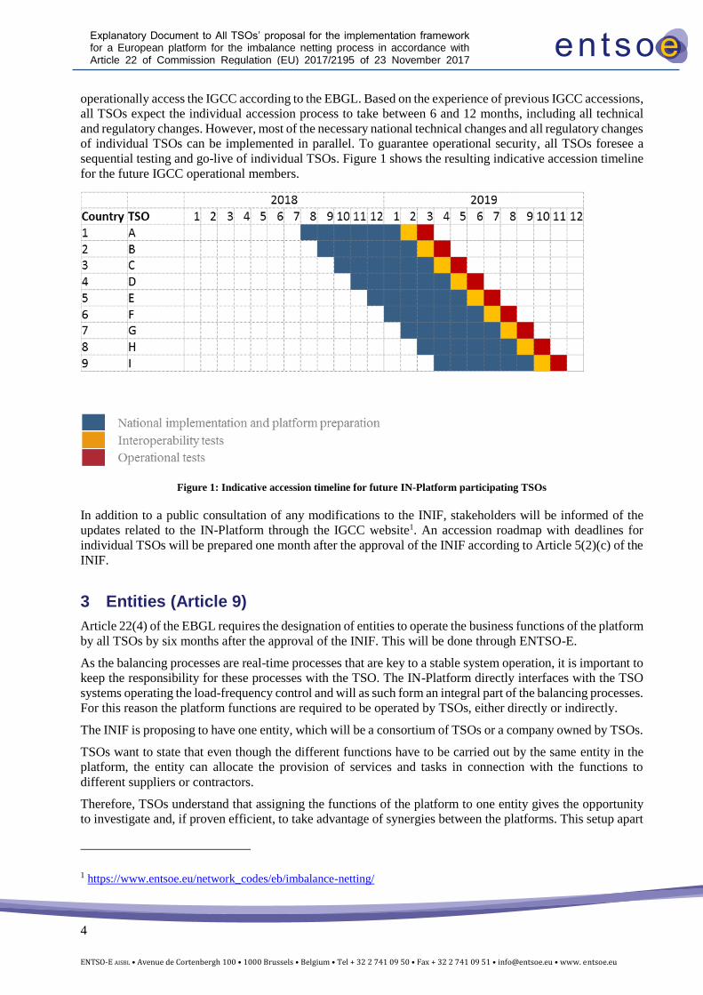
operationally access the IGCC according to the EBGL. Based on the experience of previous IGCC accessions,
all TSOs expect the individual accession process to take between 6 and 12 months, including all technical
and regulatory changes. However, most of the necessary national technical changes and all regulatory changes
of individual TSOs can be implemented in parallel. To guarantee operational security, all TSOs foresee a
sequential testing and go-live of individual TSOs. Figure 1 shows the resulting indicative accession timeline
for the future IGCC operational members.
Figure 1: Indicative accession timeline for future IN-Platform participating TSOs
In addition to a public consultation of any modifications to the INIF, stakeholders will be informed of the
updates related to the IN-Platform through the IGCC website1. An accession roadmap with deadlines for
individual TSOs will be prepared one month after the approval of the INIF according to Article 5(2)(c) of the
INIF.
3 Entities (Article 9)
Article 22(4) of the EBGL requires the designation of entities to operate the business functions of the platform
by all TSOs by six months after the approval of the INIF. This will be done through ENTSO-E.
As the balancing processes are real-time processes that are key to a stable system operation, it is important to
keep the responsibility for these processes with the TSO. The IN-Platform directly interfaces with the TSO
systems operating the load-frequency control and will as such form an integral part of the balancing processes.
For this reason the platform functions are required to be operated by TSOs, either directly or indirectly.
The INIF is proposing to have one entity, which will be a consortium of TSOs or a company owned by TSOs.
TSOs want to state that even though the different functions have to be carried out by the same entity in the
platform, the entity can allocate the provision of services and tasks in connection with the functions to
different suppliers or contractors.
Therefore, TSOs understand that assigning the functions of the platform to one entity gives the opportunity
to investigate and, if proven efficient, to take advantage of synergies between the platforms. This setup apart
1 https://www.entsoe.eu/network_codes/eb/imbalance-netting/
5
ENTSO-E AISBL • Avenue de Cortenbergh 100 • 1000 Brussels • Belgium • Tel + 32 2 741 09 50 • Fax + 32 2 741 09 51 • [email protected] • www. entsoe.eu
Explanatory Document to All TSOs’ proposal for the implementation framework for a European platform for the imbalance netting process in accordance with Article 22 of Commission Regulation (EU) 2017/2195 of 23 November 2017 establishing a guideline on electricity balancing
from being efficient from the scope of each platform allows the mutualisation of tasks or services across the
platforms in a flexible way.
This will be the case for a given task (e.g. one or some of the TSO-TSO settlement function tasks) when the
entity of every platform is able to allocate this particular task to the same TSO or service provider. This way
this task could be mutualised across the platforms.
4 Member TSOs, participating TSOs, cost sharing and decision-making
(Article 2, 7, 8 and 11)
As explained in the Article 1 of the INIF, the use of the IN-Platform is compulsory for all TSOs of the
Continental Europe synchronous area performing the automatic frequency restoration process. The deadline
for implementing and making operational of the IN-Platform is one year after the approval of the INIF.
Finally, the deadline for the TSOs in Contintental Europe to use the IN-Platform is also one year after the
approval of the INIF (subject to derogation of national regulatory authority).
Member TSOs are those TSOs that have joined the IN-Platform. These TSOs participate in the decision-
making of the Steering Committee of the platform and are responsible to implement and comply with the
decisions made. The TSOs that have the obligation to use the IN-Platform have to become member TSOs by
one year after the approval of the INIF.
Participating TSOs are member TSOs that use the IN-Platform for intended exchange of energy, i.e.: they are
a subset of member TSOs. The target is that all member TSOs will become participating TSOs by one year
after approval of INIF at the latest, subject to national derogation. The only exception would be when an LFC
area consists of more than one monitoring area. In such case, only the TSO appointed in the LFC area
operational agreement as responsible for the implementation and operation of the automatic frequency
restoration process according to Article 143(4) of the SOGL shall use the IN-Platform, i.e.: become a
participating TSO. One example for this specific case is the LFC area of Amprion, which consists of the
monitoring area of Amprion and the monitoring area of CREOS (Luxembourg). For this LFC area Amprion
is appointed as responsible for the implementation and operation of the automatic frequency restoration
process according to Article 143(4) of the SOGL. Hence, Amprion and CREOS would become both member
TSOs, but only Amprion has to become a participating TSO.
The reason to differentiate between member TSOs and participating TSOs is the following:
(a) The IGCC project may fulfil the requirements according to the INIF earlier than the deadline of one
year after the approval of the INIF, which means that the IN-Platform will be operational before that
deadline. Therefore, some member TSOs may become participating TSOs before the deadline to use
the IN-Platform, i.e.: one year after approval of the INIF.
(b) If necessary, a member TSO may apply for a derogation from using the IN-Platform by one year after
the approval of INIF. Therefore, a member TSO can become a participating TSOs later than the
deadline of one year after approval of INIF, according to granted derogation.
Member TSOs are bearing the common costs of establishing and amending the platform according to Article
11(4) and 11(8) of the INIF. However, any common operational costs according to Article 11(5) and 11(9)
of the INIF are being borne only by the participating TSOs since these are using the IN-Platform
operationally.
In order to implement and operate the IN-Platform, the member TSOs are required to make decisions through
the Steering Committee on a wide variety of topics. In doing so, TSOs will aim for unanimity and will focus
on good communication and processes to facilitate that aim. However, in case unanimity shows to be
unfeasible (for example, due to conflicting local needs), qualified majority voting will be used. The qualified
majority voting principles are modelled after those given in EBGL, although voting is done by member TSOs.
This includes member TSOs who are not yet participating TSOs. This also includes non-EU TSOs that are
member TSOs.
6
ENTSO-E AISBL • Avenue de Cortenbergh 100 • 1000 Brussels • Belgium • Tel + 32 2 741 09 50 • Fax + 32 2 741 09 51 • [email protected] • www. entsoe.eu
Explanatory Document to All TSOs’ proposal for the implementation framework for a European platform for the imbalance netting process in accordance with Article 22 of Commission Regulation (EU) 2017/2195 of 23 November 2017 establishing a guideline on electricity balancing
In case of a vote, a quorum of at least the majority (50 % + 1) of the member TSOs involved in the vote is
required. Requiring a quorum ensures that each party is aware of the voting process and that the
argumentation of all parties can be taken into account in a proper way in the decision process.
The decision process described above for member TSOs is without prejudice to the provisions of the EBGL.
This means that the decisions on the formal deliverables of the EBGL (such as the decision on the aFRRIF)
is taken according to the All TSOs’ decision process described in the EBGL. All TSOs of the European Union
will then take part, whether or not they are members of the IGCC project.
5 Framework for harmonisation of the terms and conditions related to
balancing (Article 10)
The imbalance netting process is the process that aims to minimise the amount of activated aFRR, by avoiding
their simultaneous counteractivation. The process does not require any activation of standard neither specific
products for balancing energy. Moreover, in accordance with the Article 1 of the INIF, common settlement
rules for the TSO-TSO settlement will be proposed and defined pursuant to Article 50 of the EBGL. Thus,
all TSOs consider that there is no need for harmonisation of terms and conditions related to balancing for the
establishment of the IN-Platform.
6 Description of the algorithm for the operation of imbalance netting
process function (Article 3, 4 and 12)
The optimisation algorithm is part of the imbalance netting process function. The imbalance netting process
function (INPF) calculates the corrections in real-time for each LFC area, resulting in imbalance netting
power interchanges on the imbalance netting balancing borders. This chapter describes the basic principles
of the imbalance netting process function including the interaction of load-frequency controllers of an
individual LFC area with the optimisation algorithm of the INPF, a description of the fall-back process in
case of an outage of the INPF, the interaction between the aFRR- and the IN-Platform and the congestion
management.
The inputs to the imbalance netting process function of the IN-Platform are listed in Article 3(4) of the INIF.
From this list, as further described in chapter 6.1, inputs are directly used by the algorithm on each
optimisation cycle aiming at minimizing the counteractivation of aFRR among the particpating TSO:
• the aFRR demand of every LFC area of each participating TSO being continuously reported to the
IN-Platform by each participating TSO; The aFRR demand is calculated as the sum of the already
activated aFRR and the FRCE of the respective LFC area without the influenc of the intended
exchange of balancing energy resulting from the cross-border aFRP or INP. The sign convention
for aFRR demand is: negative value where the LFC area is in power surplus and indicates that
downward aFRR balancing energy needs to be activated; and positive value where the LFC area is
in power deficit and indicates that upward aFRR balancing energy needs to be activated. For
avoidance of doubt, all aFRR demands are aFRR inelastic demands. The aFRR demand does not
consider explicitly any mFRR demand due to the nature of the INP. The INP is a real-time process
with continously changing inputs and outputs whereas in the mFRR process the in- and outputs do
not change continously, hence a consideration of the mFRR demands within the INP is not feasible.
However the mFRR activation is implicitly included in the FRCE of each LFC area;
• the imbalance netting cross-border capacity limits for the concerned imbalance netting balancing
borders or set of imbalance netting balancing borders being continuously reported to the IN-
Platform;
• the operational security constraints provided by the participating TSOs or affected TSOs in
accordance with Article 150 of the SOGL, where applicable;
7
ENTSO-E AISBL • Avenue de Cortenbergh 100 • 1000 Brussels • Belgium • Tel + 32 2 741 09 50 • Fax + 32 2 741 09 51 • [email protected] • www. entsoe.eu
Explanatory Document to All TSOs’ proposal for the implementation framework for a European platform for the imbalance netting process in accordance with Article 22 of Commission Regulation (EU) 2017/2195 of 23 November 2017 establishing a guideline on electricity balancing
Note: according to the control demand concept described in chapter 6.1 some inputs are continuously updated
at every TSO internal control cycle of its LFC (between 1 to 10 seconds). The algorithm uses the last updated
input at every optimisation cycle.
The outputs of the INPF are listed in Article 3(6) of the INIF.
6.1 Control exchange model
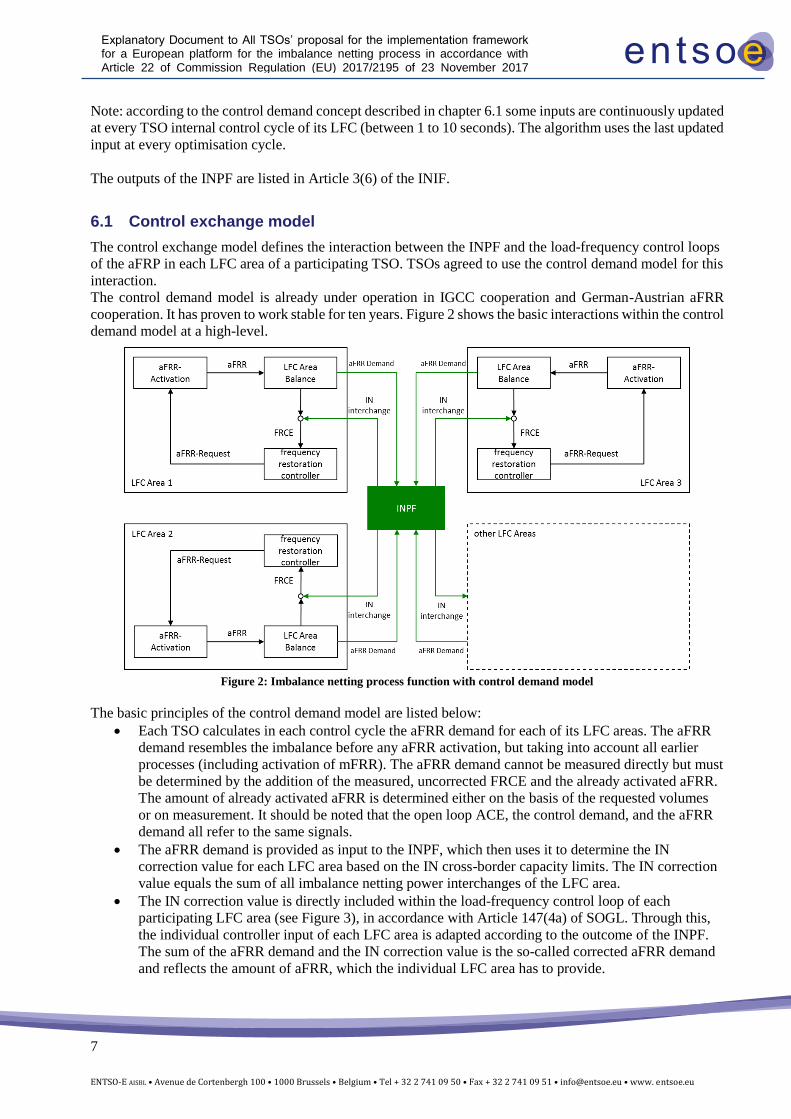
The control exchange model defines the interaction between the INPF and the load-frequency control loops
of the aFRP in each LFC area of a participating TSO. TSOs agreed to use the control demand model for this
interaction.
The control demand model is already under operation in IGCC cooperation and German-Austrian aFRR
cooperation. It has proven to work stable for ten years. Figure 2 shows the basic interactions within the control
demand model at a high-level.
Figure 2: Imbalance netting process function with control demand model
The basic principles of the control demand model are listed below:
• Each TSO calculates in each control cycle the aFRR demand for each of its LFC areas. The aFRR
demand resembles the imbalance before any aFRR activation, but taking into account all earlier
processes (including activation of mFRR). The aFRR demand cannot be measured directly but must
be determined by the addition of the measured, uncorrected FRCE and the already activated aFRR.
The amount of already activated aFRR is determined either on the basis of the requested volumes
or on measurement. It should be noted that the open loop ACE, the control demand, and the aFRR
demand all refer to the same signals.
• The aFRR demand is provided as input to the INPF, which then uses it to determine the IN
correction value for each LFC area based on the IN cross-border capacity limits. The IN correction
value equals the sum of all imbalance netting power interchanges of the LFC area.
• The IN correction value is directly included within the load-frequency control loop of each
participating LFC area (see Figure 3), in accordance with Article 147(4a) of SOGL. Through this,
the individual controller input of each LFC area is adapted according to the outcome of the INPF.
The sum of the aFRR demand and the IN correction value is the so-called corrected aFRR demand
and reflects the amount of aFRR, which the individual LFC area has to provide.
8
ENTSO-E AISBL • Avenue de Cortenbergh 100 • 1000 Brussels • Belgium • Tel + 32 2 741 09 50 • Fax + 32 2 741 09 51 • [email protected] • www. entsoe.eu
Explanatory Document to All TSOs’ proposal for the implementation framework for a European platform for the imbalance netting process in accordance with Article 22 of Commission Regulation (EU) 2017/2195 of 23 November 2017 establishing a guideline on electricity balancing
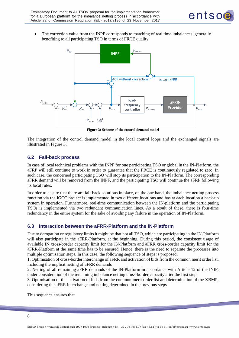
• The correction value from the INPF corresponds to matching of real time imbalances, generally
benefiting to all participating TSO in terms of FRCE quality.
Figure 3: Scheme of the control demand model
The integration of the control demand model in the local control loops and the exchanged signals are
illustrated in Figure 3.
6.2 Fall-back process
In case of local technical problems with the INPF for one participating TSO or global in the IN-Platform, the
aFRP will still continue to work in order to guarantee that the FRCE is continuously regulated to zero. In
such case, the concerned participating TSO will stop its participation to the IN-Platform. The corresponding
aFRR demand will be removed from the INPF, and the participating TSO will continue the aFRP following
its local rules.
In order to ensure that there are fall-back solutions in place, on the one hand, the imbalance netting process
function via the IGCC project is implemented in two different locations and has at each location a back-up
system in operation. Furthermore, real-time communication between the IN-platform and the participating
TSOs is implemented via two redundant communication lines. As a result of these, there is four-time
redundancy in the entire system for the sake of avoiding any failure in the operation of IN-Platform.
6.3 Interaction between the aFRR-Platform and the IN-Platform
Due to derogation or regulatory limits it might be that not all TSO, which are participating in the IN-Platform
will also participate in the aFRR-Platform, at the beginning. During this period, the consistent usage of
available IN cross-border capacity limit for the IN-Platform and aFRR cross-border capacity limit for the
aFRR-Platform at the same time has to be ensured. Hence, there is the need to separate the processes into
multiple optimisation steps. In this case, the following sequence of steps is proposed:
1. Optimisation of cross-border interchange of aFRR and activation of bids from the common merit order list,
including the implicit netting of aFRR demands
2. Netting of all remaining aFRR demands of the IN-Platform in accordance with Article 12 of the INIF,
under consideration of the remaining imbalance netting cross-border capacity after the first step
3. Optimisation of the activation of bids from the common merit order list and determination of the XBMP,
considering the aFRR interchange and netting determined in the previous steps
This sequence ensures that
9
ENTSO-E AISBL • Avenue de Cortenbergh 100 • 1000 Brussels • Belgium • Tel + 32 2 741 09 50 • Fax + 32 2 741 09 51 • [email protected] • www. entsoe.eu
Explanatory Document to All TSOs’ proposal for the implementation framework for a European platform for the imbalance netting process in accordance with Article 22 of Commission Regulation (EU) 2017/2195 of 23 November 2017 establishing a guideline on electricity balancing
• The cross-border capacity between the LFC areas that participate in the cross-border interchange of
aFRR are optimally allocated in the first step
• The priority access to aFRR capacity within an LFC block or sharing regions is ensured for aFRR-
Platform
• Merit order activation is followed for aFRR-Platform
• XBMP corresponds to the highest price of selected bid for the uncongested area of aFRR-Platform.
The steps in the sequence will be performed each optimisation cycle, which has a fixed interval of less than
10 seconds, using the aFRR demands and constraint inputs received by each participating TSO in real time.
The optimisation is performed on each optimisation cycle independently from previous optimisation cycles
outputs.
By this all TSOs participating in the aFRR-Platform and also participate in the IN-Platform will form an
optimisation region in accordance with the imbalance netting implementation framework.
Nevertheless in order to achieve simplification of the necessary optimisation steps, the TSOs recommend that
NRAs incentivise and enable the geographical regions of the participating TSOs in the aFRR-Platform to be
the same as the geographical regions of the participating TSOs in the IN-Platform, i.e. all the participating
TSOs in the IN-Platform to become participating TSOs in the aFRR-Platform.
6.4 Congestion management and calculation of the imbalance netting cross-border capacity limits (Article 4)
This chapter explains the relation between the cross-zonal capacities between bidding zones used in earlier
timeframes and the IN cross-border capacity limits on imbalance netting balancing borders used in the INPF.
Article 4 of the INIF describes how to find the limits for imbalance netting power interchange between the
LFC areas.
The imbalance netting process is defined between LFC areas, therefore, the IN-platform optimises imbalance
netting power interchanges between LFC areas, hence the limits considered in the optimisation have to be
defined for the borders between LFC areas, as explained in more detail in chapter 6.4.1. The borders between
LFC areas are defined as imbalance netting balancing borders, and the maximum limit for imbalance netting
power interchange is defined as imbalance netting cross-border capacity limits.
Chapter 6.4.2 describes how to find the imbalance netting cross-border capacity limit following the step-wise
procedure in Article 4(2). The chapter 6.4.2 also describes how the imbalance netting cross-border capacity
limits will be adjusted due to exchange of balancing energy from other processes, and the relationship with
the usage of imbalance netting cross-border capacity limits and the aFRR-platform.
Chapter 6.4.3 describes how the imbalance netting cross-border capacity limits are used by the INPF.
The congestion management process will consist of the imbalance netting cross-border capacity limits as
described in Article 4 of the INIF. Sometimes the IN cross-border capacity limits will be restricted by other
factors such as operational security. This is explained in chapter 6.4.4.
It should be noted that some countries make use of additional limitations such as for instance technical profiles
to determine their available cross-zonal capacities. This means that capacities on several borders might be
linked together. This is addressed briefly in chapter 6.4.2.1. In the remainder it should be clear that anywhere
it reads border it could be read as set of borders, so as to incorporate these technical profiles.
6.4.1 Cross-zonal capacity and LFC areas
In principle, the balancing platforms, both for exchange of balancing energy and for imbalance netting, make
use of all cross-zonal capacity available after the cross-border intraday markets, in accordance with Article
37(2) of the EBGL.
10
ENTSO-E AISBL • Avenue de Cortenbergh 100 • 1000 Brussels • Belgium • Tel + 32 2 741 09 50 • Fax + 32 2 741 09 51 • [email protected] • www. entsoe.eu
Explanatory Document to All TSOs’ proposal for the implementation framework for a European platform for the imbalance netting process in accordance with Article 22 of Commission Regulation (EU) 2017/2195 of 23 November 2017 establishing a guideline on electricity balancing
However, the aFRR demand is defined and located per LFC area. For this reason the INIF introduces
imbalance netting balancing borders, which correspond to the borders between participating LFC areas.
Normally, these imbalance netting balancing borders are the same as the aFRR balancing borders when the
particpating TSO are particpating to aFRR-Platform. Often these imbalance netting balancing borders
correspond to the bidding zone borders as well, in which case the imbalance netting cross-border capacity
limits are equal to the cross-zonal capacity on the bidding zone border remaining after intraday, corrected for
other processes as described in 6.4.2.
There are two situations in which there can be a difference between the imbalance netting balancing borders
and the bidding zone borders:
• When there are bidding zone borders inside an LFC area, these bidding zone borders do not
correspond to an imbalance netting balancing border. • When there are LFC area borders within a bidding zone, these are imbalance netting balancing
borders that do not correspond to a bidding zone border.
In case of bidding zone borders inside an LFC area it is not possible to determine how capacity on this bidding
zone borders is used due to exchange of balancing energy or imbalance netting interchange. The aFRR
demand as well as delivery cannot be further specified than the LFC area level. See also the example in 6.4.6.
In the opposite case in which there are imbalance netting balancing borders inside a bidding zone, the
algorithm still takes into account the imbalance netting cross-border capacity limits on these imbalance
netting balancing borders. For these borders an IT technical limit is defined.
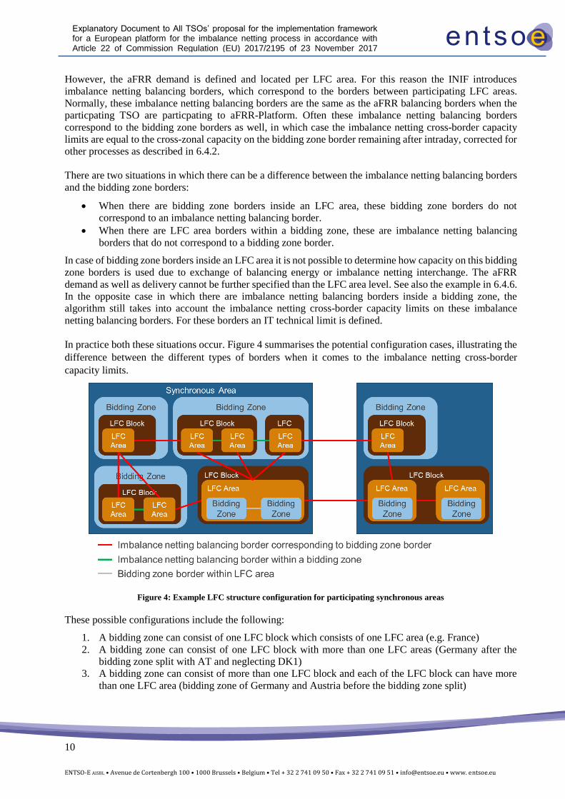
In practice both these situations occur. Figure 4 summarises the potential configuration cases, illustrating the
difference between the different types of borders when it comes to the imbalance netting cross-border
capacity limits.
Figure 4: Example LFC structure configuration for participating synchronous areas
These possible configurations include the following:
1. A bidding zone can consist of one LFC block which consists of one LFC area (e.g. France)
2. A bidding zone can consist of one LFC block with more than one LFC areas (Germany after the
bidding zone split with AT and neglecting DK1)
3. A bidding zone can consist of more than one LFC block and each of the LFC block can have more
than one LFC area (bidding zone of Germany and Austria before the bidding zone split)
11
ENTSO-E AISBL • Avenue de Cortenbergh 100 • 1000 Brussels • Belgium • Tel + 32 2 741 09 50 • Fax + 32 2 741 09 51 • [email protected] • www. entsoe.eu
Explanatory Document to All TSOs’ proposal for the implementation framework for a European platform for the imbalance netting process in accordance with Article 22 of Commission Regulation (EU) 2017/2195 of 23 November 2017 establishing a guideline on electricity balancing
4. A LFC block can consist of one LFC area which includes more than one bidding zone (Italy, current
Nordic configuration)
5. A LFC block consists of more than one LFC area where each LFC area equals one bidding zone
(future Nordic system)
In principle the imbalance netting balancing borders shall be equal to the aFRR balancing borders for the
borders also included and used in the aFRR-Platform.
6.4.2 Determination of imbalance netting cross-border capacity limits
In accordance with Article 4(2) of the INIF, each TSO shall be responsible for determining the imbalance
netting cross-border capacity limits applicable to each of his imbalance netting balancing borders and
providing these limits to the optimisation algorithm. Updated values for imbalance netting cross-border
capacity limits will be provided to the IN-Platform in real time on a local control cycle basis. The TSO will
do this by following the step-by-step process from Article 4(2) in the IF; First determining the capacity
remaining after intraday (step 1). The TSO then updates the limits for interchange in previous balancing
timeframes in line with the first-come-first-serve approach (step 2), and for any remedial actions that lead to
cross-border exchange on the imbalance netting balancing border (step 3). Finally, additional limitations may
be necessary to be taken into account for operational security reasons (step 4). The specific situation of
capacity on HVDC borders is accounted for in step 5.
All steps have to be taken but not all of them will lead to a change of the imbalance netting cross-border
capacity limits. The order in which these steps are taken can differ.
6.4.2.1 Step 1: Remaining capacity after intra-day
In the first step the remaining capacity on the borders after the energy markets is determined. How this is
done varies for the different types of borders presented in chapter 6.4.1.
If the imbalance netting balancing border correspond to a bidding zone border, the imbalance netting cross-
border capacity limits are set to be equal to the cross-zonal capacity remaining after the intraday cross-zonal
gate closure time in accordance with Article 37(2) of the EBGL. The NTC value, minus the allocation from
the day ahead and intraday markets.
For bidding zones which consists of more than one LFC area there are imbalance netting balancing borders
between these LFC areas that do not correspond to a bidding zone border. On these borders there is no cross-
zonal capacity defined. The main example of this are the imbalance netting balancing borders within
Germany. In accordance with the zonal model defined by CACM, the available capacity on these internal
imbalance netting balancing borders is assumed to not be limiting the imbalance netting energy exchanges
determined by the INPF. For this reason, the imbalance netting cross-border capacity limits on these borders
are set to a value that should not be reached as a result of realistic cross-border exchanges. All member TSOs
shall agree on the value of this technical IT limitation.
The last type of border is the result of an LFC area covering several bidding zones. Because the imbalance
netting process and the aFRR demand is defined on LFC area level, it is not possible to take the cross-zonal
capacities in these borders into account. For the INPF these borders are not considered, and thus, in practice,
considered as infinite.
If a technical profile on the sum of several borders is defined in the intraday market, such limits will also be
taken into account in the INPF. These profiles are used on some borders to limit the sum of cross-border
capacity into or out of an area without restricting the individual cross-zonal capacities. Such technical profiles
are defined for instance on the borders out of Poland.
12
ENTSO-E AISBL • Avenue de Cortenbergh 100 • 1000 Brussels • Belgium • Tel + 32 2 741 09 50 • Fax + 32 2 741 09 51 • [email protected] • www. entsoe.eu
Explanatory Document to All TSOs’ proposal for the implementation framework for a European platform for the imbalance netting process in accordance with Article 22 of Commission Regulation (EU) 2017/2195 of 23 November 2017 establishing a guideline on electricity balancing
6.4.2.2 Step 2: First-come, first-serve
In the second step, the imbalance netting cross-border capacity limits are updated on the basis of earlier
balancing processes in accordance with chapter 2 of the EBGL. This is based on a sequential first-come-first
serve approach. That is to say:
• The initial imbalance netting cross-border capacity limits are corrected for the replacement
power interchanges on the imbalance netting balancing borders. These corrected limits should
correspond to the mFRR cross-border capacity limits before any mFRR activation,
notwithstanding: o any corrections done for purposes of additional limitations in accordance with the
next step (reducing limits of both mFRR, aFRR and IN); o any corrections done for activated remedial actions (reducing limits of both mFRR,
aFRR and IN) in accordance with Article 4(2)(c) of the INIF; o any allocation of cross-zonal capacity to the aFRR and IN process (reducing limits
of mFRR to keep limits for aFRR and IN high enough), as explained below. • The aFRR and imbalance netting cross-border capacity limits are also adjusted for mFRR
activation, by correcting for the manual frequency restoration power interchanges. This, with
the corrections on remedial actions and additional limitation, then defines the aFRR and
imbalance netting cross-border capacity limits that are the input to the algorithm of the aFRR-
Platform and the IN-Platform. • These aFRR and imbalance netting cross-border capacity limits are as input to the INPF and the
aFRR AOF used for both aFRR balancing energy exchange and imbalance netting energy
exchange, as described below.
As indicated some cross-zonal capacity may have been allocated to a specific balancing process in accordance
with chapter 2 of the EBGL. This allocation is done for the exchange of balancing capacity or sharing of
reserves. In case this allocation is done for aFRR and imbalance netting, the allocation needs to be taken into
account in the distribution of cross-zonal capacity between the platforms, and will be taken into account when
applying the first-come-first-serve approach to determine the aFRR and imbalance netting cross-border
capacity limits. The aFRR and imbalance netting cross-border capacity limits should always at least be equal
to the allocated cross-zonal capacity for those aFRR and imbalance netting balancing borders that correspond
to the bidding zone borders on which the allocation for aFRR and IN has been done. This affects the RR and
mFRR cross-border capacity limits.
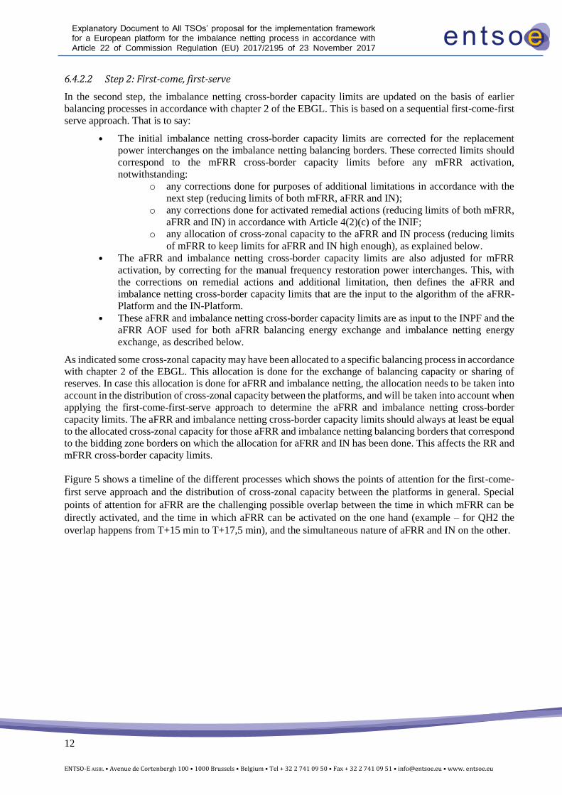
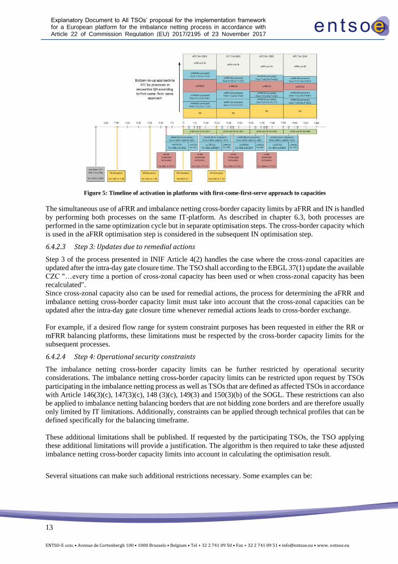
Figure 5 shows a timeline of the different processes which shows the points of attention for the first-come-
first serve approach and the distribution of cross-zonal capacity between the platforms in general. Special
points of attention for aFRR are the challenging possible overlap between the time in which mFRR can be
directly activated, and the time in which aFRR can be activated on the one hand (example – for QH2 the
overlap happens from T+15 min to T+17,5 min), and the simultaneous nature of aFRR and IN on the other.
13
ENTSO-E AISBL • Avenue de Cortenbergh 100 • 1000 Brussels • Belgium • Tel + 32 2 741 09 50 • Fax + 32 2 741 09 51 • [email protected] • www. entsoe.eu
Explanatory Document to All TSOs’ proposal for the implementation framework for a European platform for the imbalance netting process in accordance with Article 22 of Commission Regulation (EU) 2017/2195 of 23 November 2017 establishing a guideline on electricity balancing
Figure 5: Timeline of activation in platforms with first-come-first-serve approach to capacities
The simultaneous use of aFRR and imbalance netting cross-border capacity limits by aFRR and IN is handled
by performing both processes on the same IT-platform. As described in chapter 6.3, both processes are
performed in the same optimization cycle but in separate optimisation steps. The cross-border capacity which
is used in the aFRR optimisation step is considered in the subsequent IN optimisation step.
6.4.2.3 Step 3: Updates due to remedial actions
Step 3 of the process presented in INIF Article 4(2) handles the case where the cross-zonal capacities are
updated after the intra-day gate closure time. The TSO shall according to the EBGL 37(1) update the available
CZC "…every time a portion of cross-zonal capacity has been used or when cross-zonal capacity has been
recalculated".
Since cross-zonal capacity also can be used for remedial actions, the process for determining the aFRR and
imbalance netting cross-border capacity limit must take into account that the cross-zonal capacities can be
updated after the intra-day gate closure time whenever remedial actions leads to cross-border exchange.
For example, if a desired flow range for system constraint purposes has been requested in either the RR or
mFRR balancing platforms, these limitations must be respected by the cross-border capacity limits for the
subsequent processes.
6.4.2.4 Step 4: Operational security constraints
The imbalance netting cross-border capacity limits can be further restricted by operational security
considerations. The imbalance netting cross-border capacity limits can be restricted upon request by TSOs
participating in the imbalance netting process as well as TSOs that are defined as affected TSOs in accordance
with Article 146(3)(c), 147(3)(c), 148 (3)(c), 149(3) and 150(3)(b) of the SOGL. These restrictions can also
be applied to imbalance netting balancing borders that are not bidding zone borders and are therefore usually
only limited by IT limitations. Additionally, constraints can be applied through technical profiles that can be
defined specifically for the balancing timeframe.
These additional limitations shall be published. If requested by the participating TSOs, the TSO applying
these additional limitations will provide a justification. The algorithm is then required to take these adjusted
imbalance netting cross-border capacity limits into account in calculating the optimisation result.
Several situations can make such additional restrictions necessary. Some examples can be:
14
ENTSO-E AISBL • Avenue de Cortenbergh 100 • 1000 Brussels • Belgium • Tel + 32 2 741 09 50 • Fax + 32 2 741 09 51 • [email protected] • www. entsoe.eu
Explanatory Document to All TSOs’ proposal for the implementation framework for a European platform for the imbalance netting process in accordance with Article 22 of Commission Regulation (EU) 2017/2195 of 23 November 2017 establishing a guideline on electricity balancing
• An affected TSO can experience flows within its area due to imbalance netting power interchange
over another area ;
• The total exchange in or out an area can lead to congestions within an LFC area ;
• An outage or another sudden event in the power system can reduce the available capacity out of an
LFC area.
6.4.2.5 Step 5: Technical constraints
Step 5 takes into account that not all imbalance netting balancing borders consisting of HVDC interconnectors
have the technical ability to exchange IN, or that the technical ability may be more or less limited. HVDC
interconnectors vary in technology and specification, and will have different properties affecting their ability
to transfer imbalance netting power interchange.
Some connections might not be available for IN at all, while some might have restrictions related to zero-
crossings, minimum volumes, maximum ramping rates or other technical restrictions.
6.4.3 Treatment of imbalance netting cross-border capacity limits in the INPF
Imbalance netting cross-border capacity limits on all imbalance netting balancing border will be used as
constraints of the objective function of INPF. The INPF will make sure that the imbalance netting power
interchange on imbalance netting balancing borders resulting from the optimisation does not exceed the
corresponding imbalance netting cross-border capacity limits.
If the imbalance netting cross-border capacity limits do not constrain the optimisation, the entire IN-Platform
area will form one uncongested area. On the other hand, if the optimisation problem is constrained, several
uncongested areas will be defined and separated at the imbalance netting balancing borders where the
congestion occurred. When forming two uncongested areas the power interchange between the areas will
always equal the imbalance netting cross-border capacity limits.
When the INPF form several uncongested areas this will influence the proportional distribution of netting
potential.
6.4.4 Other measures for operational security
In addition to restricting the imbalance netting cross-border capacity limit, it can be beneficial to provide
other kinds of limitations. Article 3(4)(d) of the IF describes as an input to the INPF operational security
constraints provided by the participating TSOs or affected TSOs in accordance with Article 146, 147, 148,
149 and 150 of the SOGL.
This can for example be a maximum limit of the net imbalance netting power interchange from one LFC area,
or other measures that the TSO finds necessary.
6.4.5 Future development
The TSOs shall within five years after entry into force of the EBGL develop a methodology for cross-zonal
capacity calculation within the balancing timeframe. Once the methodology pursuant Article 37(3) of the
EBGL is approved and implemented, the imbalance netting cross-border capacity limits shall respect this
capacity calculation methodology.
If parts of the whole European intraday market are performed in a flow-based domain, an extraction of
available cross-zonal capacity per bidding zone border will be used, comparable to the process between the
market coupling in the CWE region and the succeeding intraday market. The part of this available cross-zonal
capacity used for the imbalance netting process will take into account previous balancing processes as
described in 6.4.2. In any case, only available cross-zonal capacities will be used for the imbalance netting
process, the transmission reliability margin of TSOs will not be used by the IN-Platform.
6.4.6 Example
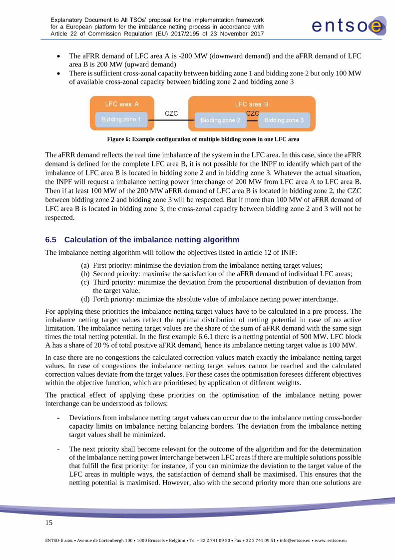
Consider the configuration as in Figure 6, and assume:
15
ENTSO-E AISBL • Avenue de Cortenbergh 100 • 1000 Brussels • Belgium • Tel + 32 2 741 09 50 • Fax + 32 2 741 09 51 • [email protected] • www. entsoe.eu
Explanatory Document to All TSOs’ proposal for the implementation framework for a European platform for the imbalance netting process in accordance with Article 22 of Commission Regulation (EU) 2017/2195 of 23 November 2017 establishing a guideline on electricity balancing
• The aFRR demand of LFC area A is -200 MW (downward demand) and the aFRR demand of LFC
area B is 200 MW (upward demand) • There is sufficient cross-zonal capacity between bidding zone 1 and bidding zone 2 but only 100 MW
of available cross-zonal capacity between bidding zone 2 and bidding zone 3
Figure 6: Example configuration of multiple bidding zones in one LFC area
The aFRR demand reflects the real time imbalance of the system in the LFC area. In this case, since the aFRR
demand is defined for the complete LFC area B, it is not possible for the INPF to identify which part of the
imbalance of LFC area B is located in bidding zone 2 and in bidding zone 3. Whatever the actual situation,
the INPF will request a imbalance netting power interchange of 200 MW from LFC area A to LFC area B.
Then if at least 100 MW of the 200 MW aFRR demand of LFC area B is located in bidding zone 2, the CZC
between bidding zone 2 and bidding zone 3 will be respected. But if more than 100 MW of aFRR demand of
LFC area B is located in bidding zone 3, the cross-zonal capacity between bidding zone 2 and 3 will not be
respected.
6.5 Calculation of the imbalance netting algorithm
The imbalance netting algorithm will follow the objectives listed in article 12 of INIF:
(a) First priority: minimise the deviation from the imbalance netting target values;
(b) Second priority: maximise the satisfaction of the aFRR demand of individual LFC areas;
(c) Third priority: minimize the deviation from the proportional distribution of deviation from
the target value;
(d) Forth priority: minimize the absolute value of imbalance netting power interchange.
For applying these priorities the imbalance netting target values have to be calculated in a pre-process. The
imbalance netting target values reflect the optimal distribution of netting potential in case of no active
limitation. The imbalance netting target values are the share of the sum of aFRR demand with the same sign
times the total netting potential. In the first example 6.6.1 there is a netting potential of 500 MW. LFC block
A has a share of 20 % of total positive aFRR demand, hence its imbalance netting target value is 100 MW.
In case there are no congestions the calculated correction values match exactly the imbalance netting target
values. In case of congestions the imbalance netting target values cannot be reached and the calculated
correction values deviate from the target values. For these cases the optimisation foresees different objectives
within the objective function, which are prioritiesed by application of different weights.
The practical effect of applying these priorities on the optimisation of the imbalance netting power
interchange can be understood as follows:
- Deviations from imbalance netting target values can occur due to the imbalance netting cross-border
capacity limits on imbalance netting balancing borders. The deviation from the imbalance netting
target values shall be minimized.
- The next priority shall become relevant for the outcome of the algorithm and for the determination
of the imbalance netting power interchange between LFC areas if there are multiple solutions possible
that fulfill the first priority: for instance, if you can minimize the deviation to the target value of the
LFC areas in multiple ways, the satisfaction of demand shall be maximised. This ensures that the
netting potential is maximised. However, also with the second priority more than one solutions are
16
ENTSO-E AISBL • Avenue de Cortenbergh 100 • 1000 Brussels • Belgium • Tel + 32 2 741 09 50 • Fax + 32 2 741 09 51 • [email protected] • www. entsoe.eu
Explanatory Document to All TSOs’ proposal for the implementation framework for a European platform for the imbalance netting process in accordance with Article 22 of Commission Regulation (EU) 2017/2195 of 23 November 2017 establishing a guideline on electricity balancing
possible. To ensure fairness between the LFC areas the third objective strives for proportional
distribution of the deviations from the target values.
- The objective of the fourth rule of power exchange minimization is to choose the optimal solution
which uses the least cross-border capacity when several solutions fulfil all earlier objectives.
In the following subchapters, examples are provided for better understanding.
6.6 Examples for the calculation of the imbalance netting algorithm
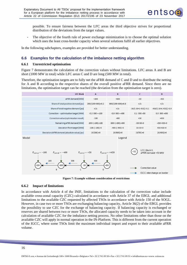
6.6.1 Unrestricted optimisation
Figure 7 demonstrates the calculation of the correction values without limitations. LFC areas A and B are
short (1000 MW in total) while LFC areas C and D are long (500 MW in total).
Therefore, the optimisation targets are to fully net the aFRR demand of C and D and to distribute the netting
for A and B according to the respective shares of the overall positive aFRR demand. Since there are no
limitations, the optimisation target can be reached (the deviation from the optimisation target is zero).
Figure 7: Example without consideration of restrictions
6.6.2 Impact of limitations
In accordance with Article 4 of the INIF, limitations to the calculation of the correction value include
available cross-zonal capacity (CZC) calculated in accordance with Article 37 of the EBGL and additional
limitations to the available CZC requested by affected TSOs in accordance with Article 150 of the SOGL.
However, in case two or more TSOs are exchanging balancing capacity, Article 36(2) of the EBGL provides
the possibility to use CZC for the exchange of balancing capacity. If balancing capacity is exchanged or
reserves are shared between two or more TSOs, the allocated capacity needs to be taken into account in the
calculation of available CZC for the imbalance netting process. No other limitations other than those on the
available CZC will apply in normal operation in the IN-Platform. This is different from the current operation
of the IGCC, where some TSOs limit the maximum individual import and export to their available aFRR
volume.
17
ENTSO-E AISBL • Avenue de Cortenbergh 100 • 1000 Brussels • Belgium • Tel + 32 2 741 09 50 • Fax + 32 2 741 09 51 • [email protected] • www. entsoe.eu
Explanatory Document to All TSOs’ proposal for the implementation framework for a European platform for the imbalance netting process in accordance with Article 22 of Commission Regulation (EU) 2017/2195 of 23 November 2017 establishing a guideline on electricity balancing
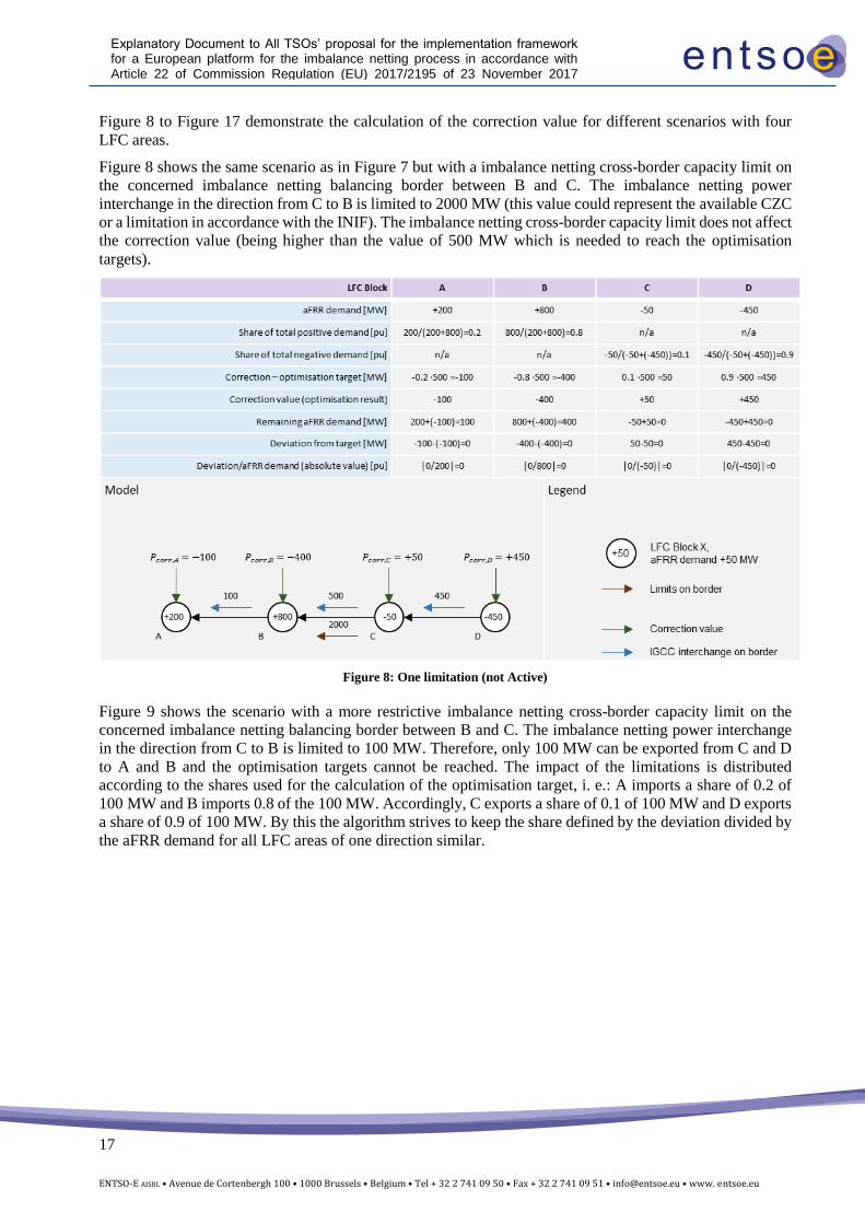
Figure 8 to Figure 17 demonstrate the calculation of the correction value for different scenarios with four
LFC areas.
Figure 8 shows the same scenario as in Figure 7 but with a imbalance netting cross-border capacity limit on
the concerned imbalance netting balancing border between B and C. The imbalance netting power
interchange in the direction from C to B is limited to 2000 MW (this value could represent the available CZC
or a limitation in accordance with the INIF). The imbalance netting cross-border capacity limit does not affect
the correction value (being higher than the value of 500 MW which is needed to reach the optimisation
targets).
Figure 8: One limitation (not Active)
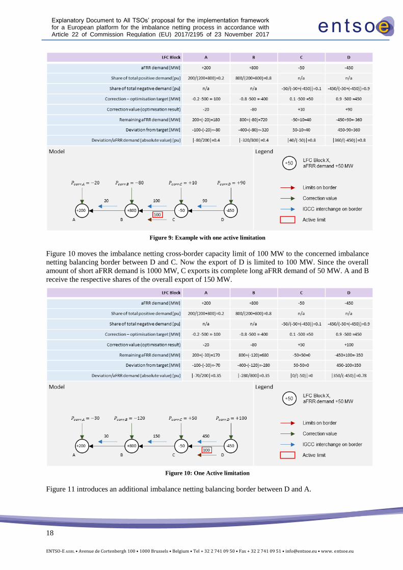
Figure 9 shows the scenario with a more restrictive imbalance netting cross-border capacity limit on the
concerned imbalance netting balancing border between B and C. The imbalance netting power interchange
in the direction from C to B is limited to 100 MW. Therefore, only 100 MW can be exported from C and D
to A and B and the optimisation targets cannot be reached. The impact of the limitations is distributed
according to the shares used for the calculation of the optimisation target, i. e.: A imports a share of 0.2 of
100 MW and B imports 0.8 of the 100 MW. Accordingly, C exports a share of 0.1 of 100 MW and D exports
a share of 0.9 of 100 MW. By this the algorithm strives to keep the share defined by the deviation divided by
the aFRR demand for all LFC areas of one direction similar.
18
ENTSO-E AISBL • Avenue de Cortenbergh 100 • 1000 Brussels • Belgium • Tel + 32 2 741 09 50 • Fax + 32 2 741 09 51 • [email protected] • www. entsoe.eu
Explanatory Document to All TSOs’ proposal for the implementation framework for a European platform for the imbalance netting process in accordance with Article 22 of Commission Regulation (EU) 2017/2195 of 23 November 2017 establishing a guideline on electricity balancing
Figure 9: Example with one active limitation
Figure 10 moves the imbalance netting cross-border capacity limit of 100 MW to the concerned imbalance
netting balancing border between D and C. Now the export of D is limited to 100 MW. Since the overall
amount of short aFRR demand is 1000 MW, C exports its complete long aFRR demand of 50 MW. A and B
receive the respective shares of the overall export of 150 MW.
Figure 10: One Active limitation
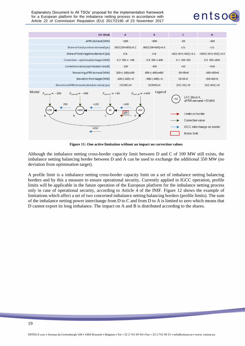
Figure 11 introduces an additional imbalance netting balancing border between D and A.
19
ENTSO-E AISBL • Avenue de Cortenbergh 100 • 1000 Brussels • Belgium • Tel + 32 2 741 09 50 • Fax + 32 2 741 09 51 • [email protected] • www. entsoe.eu
Explanatory Document to All TSOs’ proposal for the implementation framework for a European platform for the imbalance netting process in accordance with Article 22 of Commission Regulation (EU) 2017/2195 of 23 November 2017 establishing a guideline on electricity balancing
Figure 11: One active limitation without an impact on correction values
Although the imbalance netting cross-border capacity limit between D and C of 100 MW still exists, the
imbalance netting balancing border between D and A can be used to exchange the additional 350 MW (no
deviation from optimisation target).
A profile limit is a imbalance netting cross-border capacity limit on a set of imbalance netting balancing
borders and by this a measure to ensure operational security. Currently applied in IGCC operation, profile
limits will be applicable in the future operation of the European platform for the imbalance netting process
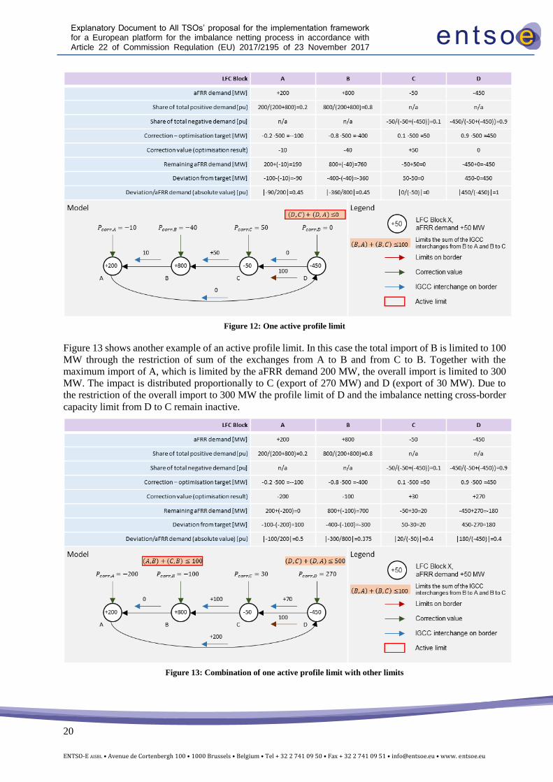
only in case of operational security, according to Article 4 of the INIF. Figure 12 shows the example of
limitations which affect a set of two concerned imbalance netting balancing borders (profile limits). The sum
of the imbalance netting power interchange from D to C and from D to A is limited to zero which means that
D cannot export its long imbalance. The impact on A and B is distributed according to the shares.
20
ENTSO-E AISBL • Avenue de Cortenbergh 100 • 1000 Brussels • Belgium • Tel + 32 2 741 09 50 • Fax + 32 2 741 09 51 • [email protected] • www. entsoe.eu
Explanatory Document to All TSOs’ proposal for the implementation framework for a European platform for the imbalance netting process in accordance with Article 22 of Commission Regulation (EU) 2017/2195 of 23 November 2017 establishing a guideline on electricity balancing
Figure 12: One active profile limit
Figure 13 shows another example of an active profile limit. In this case the total import of B is limited to 100
MW through the restriction of sum of the exchanges from A to B and from C to B. Together with the
maximum import of A, which is limited by the aFRR demand 200 MW, the overall import is limited to 300
MW. The impact is distributed proportionally to C (export of 270 MW) and D (export of 30 MW). Due to
the restriction of the overall import to 300 MW the profile limit of D and the imbalance netting cross-border
capacity limit from D to C remain inactive.
Figure 13: Combination of one active profile limit with other limits
21
ENTSO-E AISBL • Avenue de Cortenbergh 100 • 1000 Brussels • Belgium • Tel + 32 2 741 09 50 • Fax + 32 2 741 09 51 • [email protected] • www. entsoe.eu
Explanatory Document to All TSOs’ proposal for the implementation framework for a European platform for the imbalance netting process in accordance with Article 22 of Commission Regulation (EU) 2017/2195 of 23 November 2017 establishing a guideline on electricity balancing
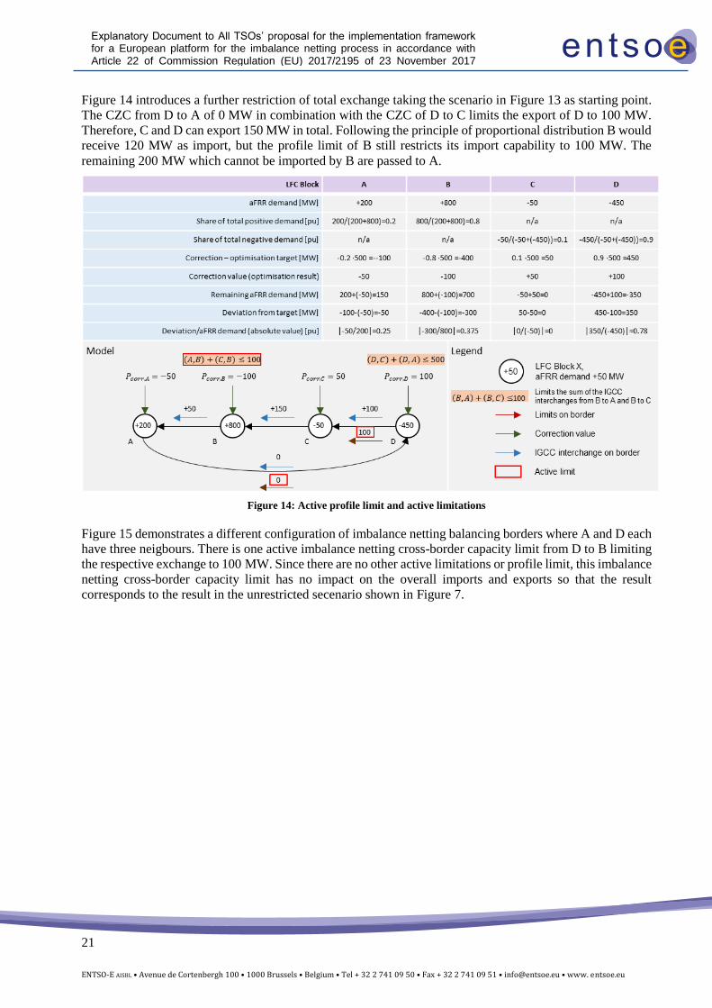
Figure 14 introduces a further restriction of total exchange taking the scenario in Figure 13 as starting point.
The CZC from D to A of 0 MW in combination with the CZC of D to C limits the export of D to 100 MW.
Therefore, C and D can export 150 MW in total. Following the principle of proportional distribution B would
receive 120 MW as import, but the profile limit of B still restricts its import capability to 100 MW. The
remaining 200 MW which cannot be imported by B are passed to A.
Figure 14: Active profile limit and active limitations
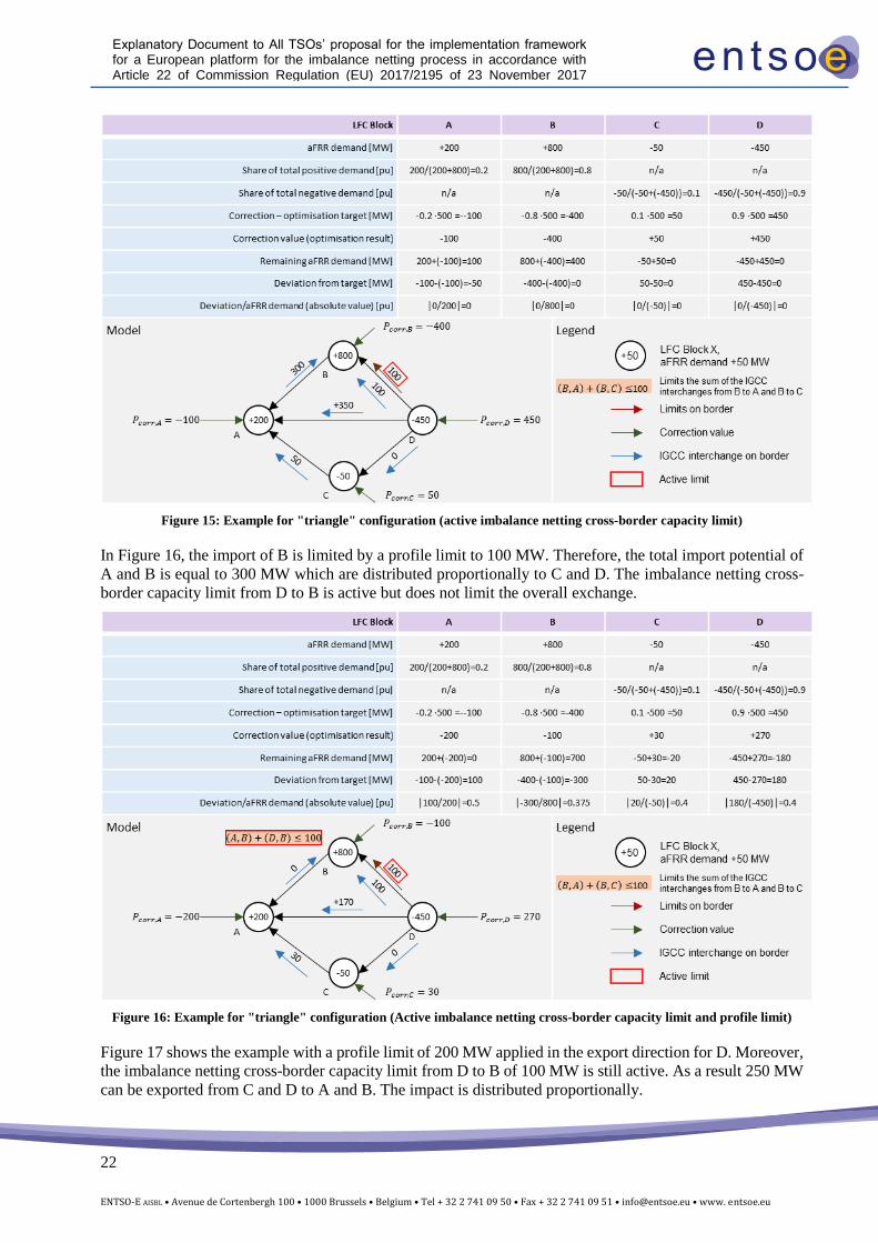
Figure 15 demonstrates a different configuration of imbalance netting balancing borders where A and D each
have three neigbours. There is one active imbalance netting cross-border capacity limit from D to B limiting
the respective exchange to 100 MW. Since there are no other active limitations or profile limit, this imbalance
netting cross-border capacity limit has no impact on the overall imports and exports so that the result
corresponds to the result in the unrestricted secenario shown in Figure 7.
22
ENTSO-E AISBL • Avenue de Cortenbergh 100 • 1000 Brussels • Belgium • Tel + 32 2 741 09 50 • Fax + 32 2 741 09 51 • [email protected] • www. entsoe.eu
Explanatory Document to All TSOs’ proposal for the implementation framework for a European platform for the imbalance netting process in accordance with Article 22 of Commission Regulation (EU) 2017/2195 of 23 November 2017 establishing a guideline on electricity balancing
Figure 15: Example for "triangle" configuration (active imbalance netting cross-border capacity limit)
In Figure 16, the import of B is limited by a profile limit to 100 MW. Therefore, the total import potential of
A and B is equal to 300 MW which are distributed proportionally to C and D. The imbalance netting cross-
border capacity limit from D to B is active but does not limit the overall exchange.
Figure 16: Example for "triangle" configuration (Active imbalance netting cross-border capacity limit and profile limit)
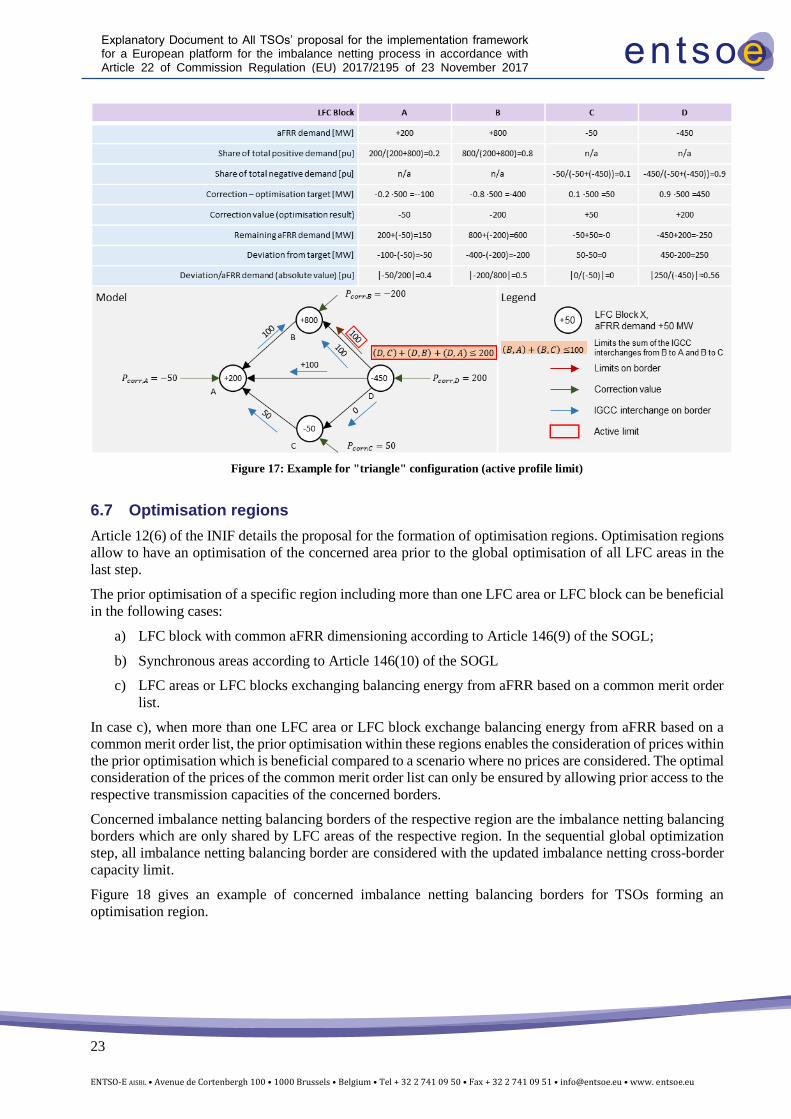
Figure 17 shows the example with a profile limit of 200 MW applied in the export direction for D. Moreover,
the imbalance netting cross-border capacity limit from D to B of 100 MW is still active. As a result 250 MW
can be exported from C and D to A and B. The impact is distributed proportionally.
23
ENTSO-E AISBL • Avenue de Cortenbergh 100 • 1000 Brussels • Belgium • Tel + 32 2 741 09 50 • Fax + 32 2 741 09 51 • [email protected] • www. entsoe.eu
Explanatory Document to All TSOs’ proposal for the implementation framework for a European platform for the imbalance netting process in accordance with Article 22 of Commission Regulation (EU) 2017/2195 of 23 November 2017 establishing a guideline on electricity balancing
Figure 17: Example for "triangle" configuration (active profile limit)
6.7 Optimisation regions
Article 12(6) of the INIF details the proposal for the formation of optimisation regions. Optimisation regions
allow to have an optimisation of the concerned area prior to the global optimisation of all LFC areas in the
last step.
The prior optimisation of a specific region including more than one LFC area or LFC block can be beneficial
in the following cases:
a) LFC block with common aFRR dimensioning according to Article 146(9) of the SOGL;
b) Synchronous areas according to Article 146(10) of the SOGL
c) LFC areas or LFC blocks exchanging balancing energy from aFRR based on a common merit order
list.
In case c), when more than one LFC area or LFC block exchange balancing energy from aFRR based on a
common merit order list, the prior optimisation within these regions enables the consideration of prices within
the prior optimisation which is beneficial compared to a scenario where no prices are considered. The optimal
consideration of the prices of the common merit order list can only be ensured by allowing prior access to the
respective transmission capacities of the concerned borders.
Concerned imbalance netting balancing borders of the respective region are the imbalance netting balancing
borders which are only shared by LFC areas of the respective region. In the sequential global optimization
step, all imbalance netting balancing border are considered with the updated imbalance netting cross-border
capacity limit.
Figure 18 gives an example of concerned imbalance netting balancing borders for TSOs forming an
optimisation region.
24
ENTSO-E AISBL • Avenue de Cortenbergh 100 • 1000 Brussels • Belgium • Tel + 32 2 741 09 50 • Fax + 32 2 741 09 51 • [email protected] • www. entsoe.eu
Explanatory Document to All TSOs’ proposal for the implementation framework for a European platform for the imbalance netting process in accordance with Article 22 of Commission Regulation (EU) 2017/2195 of 23 November 2017 establishing a guideline on electricity balancing
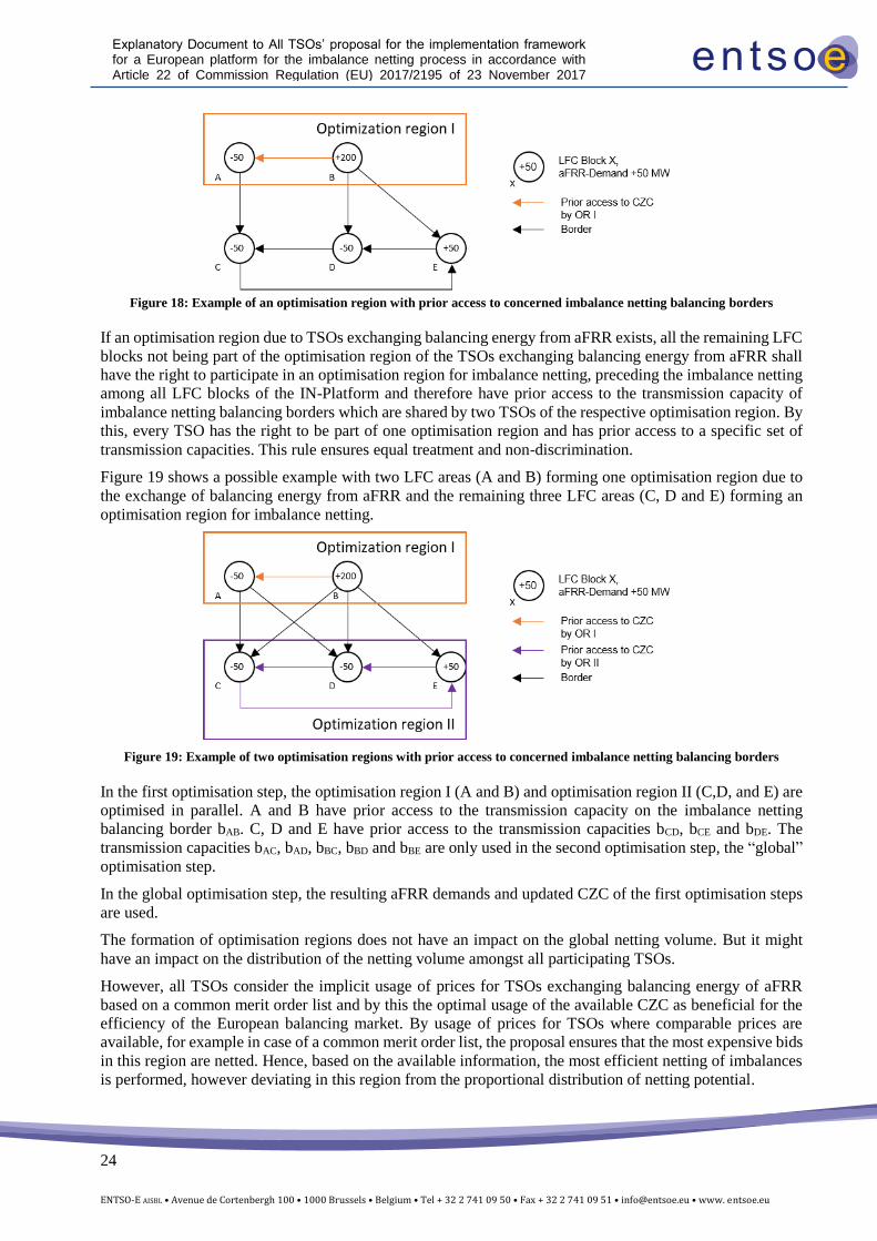
Figure 18: Example of an optimisation region with prior access to concerned imbalance netting balancing borders
If an optimisation region due to TSOs exchanging balancing energy from aFRR exists, all the remaining LFC
blocks not being part of the optimisation region of the TSOs exchanging balancing energy from aFRR shall
have the right to participate in an optimisation region for imbalance netting, preceding the imbalance netting
among all LFC blocks of the IN-Platform and therefore have prior access to the transmission capacity of
imbalance netting balancing borders which are shared by two TSOs of the respective optimisation region. By
this, every TSO has the right to be part of one optimisation region and has prior access to a specific set of
transmission capacities. This rule ensures equal treatment and non-discrimination.
Figure 19 shows a possible example with two LFC areas (A and B) forming one optimisation region due to
the exchange of balancing energy from aFRR and the remaining three LFC areas (C, D and E) forming an
optimisation region for imbalance netting.
Figure 19: Example of two optimisation regions with prior access to concerned imbalance netting balancing borders
In the first optimisation step, the optimisation region I (A and B) and optimisation region II (C,D, and E) are
optimised in parallel. A and B have prior access to the transmission capacity on the imbalance netting
balancing border bAB. C, D and E have prior access to the transmission capacities bCD, bCE and bDE. The
transmission capacities bAC, bAD, bBC, bBD and bBE are only used in the second optimisation step, the “global”
optimisation step.
In the global optimisation step, the resulting aFRR demands and updated CZC of the first optimisation steps
are used.
The formation of optimisation regions does not have an impact on the global netting volume. But it might
have an impact on the distribution of the netting volume amongst all participating TSOs.
However, all TSOs consider the implicit usage of prices for TSOs exchanging balancing energy of aFRR
based on a common merit order list and by this the optimal usage of the available CZC as beneficial for the
efficiency of the European balancing market. By usage of prices for TSOs where comparable prices are
available, for example in case of a common merit order list, the proposal ensures that the most expensive bids
in this region are netted. Hence, based on the available information, the most efficient netting of imbalances
is performed, however deviating in this region from the proportional distribution of netting potential.
25
ENTSO-E AISBL • Avenue de Cortenbergh 100 • 1000 Brussels • Belgium • Tel + 32 2 741 09 50 • Fax + 32 2 741 09 51 • [email protected] • www. entsoe.eu
Explanatory Document to All TSOs’ proposal for the implementation framework for a European platform for the imbalance netting process in accordance with Article 22 of Commission Regulation (EU) 2017/2195 of 23 November 2017 establishing a guideline on electricity balancing
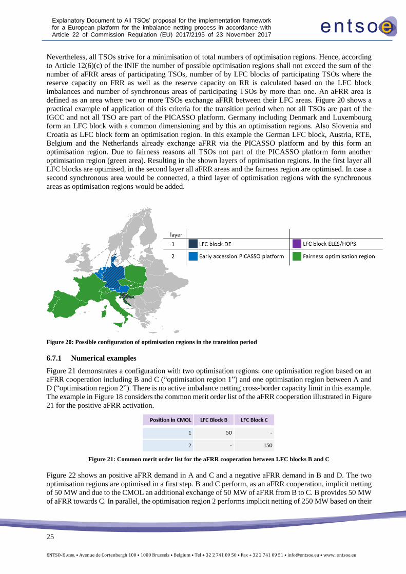
Nevertheless, all TSOs strive for a minimisation of total numbers of optimisation regions. Hence, according
to Article 12(6)(c) of the INIF the number of possible optimisation regions shall not exceed the sum of the
number of aFRR areas of participating TSOs, number of by LFC blocks of participating TSOs where the
reserve capacity on FRR as well as the reserve capacity on RR is calculated based on the LFC block
imbalances and number of synchronous areas of participating TSOs by more than one. An aFRR area is
defined as an area where two or more TSOs exchange aFRR between their LFC areas. Figure 20 shows a
practical example of application of this criteria for the transition period when not all TSOs are part of the
IGCC and not all TSO are part of the PICASSO platform. Germany including Denmark and Luxembourg
form an LFC block with a common dimensioning and by this an optimisation regions. Also Slovenia and
Croatia as LFC block form an optimisation region. In this example the German LFC block, Austria, RTE,
Belgium and the Netherlands already exchange aFRR via the PICASSO platform and by this form an
optimisation region. Due to fairness reasons all TSOs not part of the PICASSO platform form another
optimisation region (green area). Resulting in the shown layers of optimisation regions. In the first layer all
LFC blocks are optimised, in the second layer all aFRR areas and the fairness region are optimised. In case a
second synchronous area would be connected, a third layer of optimisation regions with the synchronous
areas as optimisation regions would be added.
Figure 20: Possible configuration of optimisation regions in the transition period
6.7.1 Numerical examples
Figure 21 demonstrates a configuration with two optimisation regions: one optimisation region based on an
aFRR cooperation including B and C (“optimisation region 1”) and one optimisation region between A and
D (“optimisation region 2”). There is no active imbalance netting cross-border capacity limit in this example.
The example in Figure 18 considers the common merit order list of the aFRR cooperation illustrated in Figure
21 for the positive aFRR activation.
Figure 21: Common merit order list for the aFRR cooperation between LFC blocks B and C
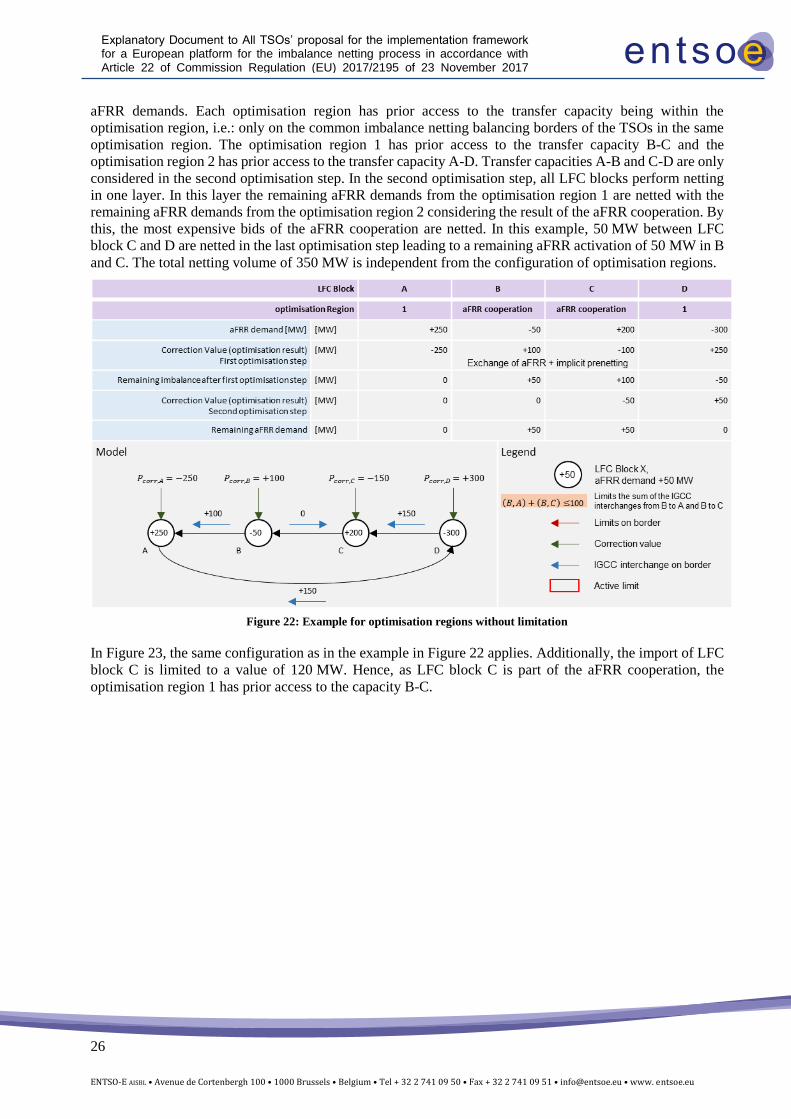
Figure 22 shows an positive aFRR demand in A and C and a negative aFRR demand in B and D. The two
optimisation regions are optimised in a first step. B and C perform, as an aFRR cooperation, implicit netting
of 50 MW and due to the CMOL an additional exchange of 50 MW of aFRR from B to C. B provides 50 MW
of aFRR towards C. In parallel, the optimisation region 2 performs implicit netting of 250 MW based on their
26
ENTSO-E AISBL • Avenue de Cortenbergh 100 • 1000 Brussels • Belgium • Tel + 32 2 741 09 50 • Fax + 32 2 741 09 51 • [email protected] • www. entsoe.eu
Explanatory Document to All TSOs’ proposal for the implementation framework for a European platform for the imbalance netting process in accordance with Article 22 of Commission Regulation (EU) 2017/2195 of 23 November 2017 establishing a guideline on electricity balancing
aFRR demands. Each optimisation region has prior access to the transfer capacity being within the
optimisation region, i.e.: only on the common imbalance netting balancing borders of the TSOs in the same
optimisation region. The optimisation region 1 has prior access to the transfer capacity B-C and the
optimisation region 2 has prior access to the transfer capacity A-D. Transfer capacities A-B and C-D are only
considered in the second optimisation step. In the second optimisation step, all LFC blocks perform netting
in one layer. In this layer the remaining aFRR demands from the optimisation region 1 are netted with the
remaining aFRR demands from the optimisation region 2 considering the result of the aFRR cooperation. By
this, the most expensive bids of the aFRR cooperation are netted. In this example, 50 MW between LFC
block C and D are netted in the last optimisation step leading to a remaining aFRR activation of 50 MW in B
and C. The total netting volume of 350 MW is independent from the configuration of optimisation regions.
Figure 22: Example for optimisation regions without limitation
In Figure 23, the same configuration as in the example in Figure 22 applies. Additionally, the import of LFC
block C is limited to a value of 120 MW. Hence, as LFC block C is part of the aFRR cooperation, the
optimisation region 1 has prior access to the capacity B-C.
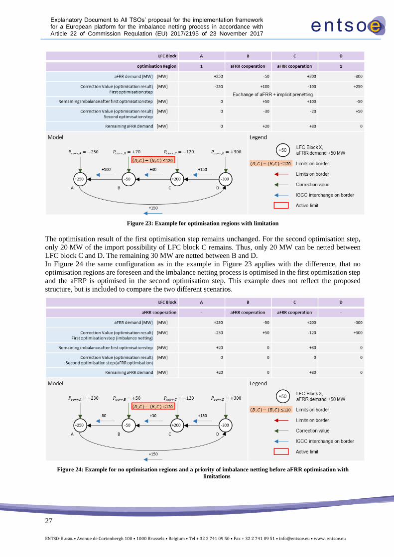
27
ENTSO-E AISBL • Avenue de Cortenbergh 100 • 1000 Brussels • Belgium • Tel + 32 2 741 09 50 • Fax + 32 2 741 09 51 • [email protected] • www. entsoe.eu
Explanatory Document to All TSOs’ proposal for the implementation framework for a European platform for the imbalance netting process in accordance with Article 22 of Commission Regulation (EU) 2017/2195 of 23 November 2017 establishing a guideline on electricity balancing
Figure 23: Example for optimisation regions with limitation
The optimisation result of the first optimisation step remains unchanged. For the second optimisation step,
only 20 MW of the import possibility of LFC block C remains. Thus, only 20 MW can be netted between
LFC block C and D. The remaining 30 MW are netted between B and D.
In Figure 24 the same configuration as in the example in Figure 23 applies with the difference, that no
optimisation regions are foreseen and the imbalance netting process is optimised in the first optimisation step
and the aFRP is optimised in the second optimisation step. This example does not reflect the proposed
structure, but is included to compare the two different scenarios.
Figure 24: Example for no optimisation regions and a priority of imbalance netting before aFRR optimisation with
limitations
28
ENTSO-E AISBL • Avenue de Cortenbergh 100 • 1000 Brussels • Belgium • Tel + 32 2 741 09 50 • Fax + 32 2 741 09 51 • [email protected] • www. entsoe.eu
Explanatory Document to All TSOs’ proposal for the implementation framework for a European platform for the imbalance netting process in accordance with Article 22 of Commission Regulation (EU) 2017/2195 of 23 November 2017 establishing a guideline on electricity balancing
Due to the profile limit in LFC area C the optimisation of the imbalance netting process deviates from the
optimisation target. LFC area A receives a higher share of the total netting potential. In the second
optimisation step no aFRR optimisation can be performed as the updated profile limit of LFC area is zero
and by this LFC area C can no further import. Hence, the available price information cannot be used to
improve the optimisation result. The overall netted volume of 350 MW is the same as in the example before.
7 Publication of information and reporting
Pursuant to Article 12 of EBGL, there is no specific requirement to publish the intended exchanges of energy
as a result of the imbalance netting process. However, TSOs plan to keep the current practice of publishing
this information and to continue publishing the social welfare reports on the ENTSO-E website2.
In accordance with Article 12(3)(k) of EBGL, in case there is any amendment of the algorithm of the
imbalance netting process function, the requirements shall be published at least one month before the
application.
Considering Article 12(3)(l) and Article 59(3) of EBGL, ENTSO-E shall publish a European report which,
amongst others, shall describe the status of implementation projects and also assess the compatibility between
the implementation projects. These reports shall be published online.
2 https://www.entsoe.eu/network_codes/eb/imbalance-netting/