Embed Size (px)
Citation preview
Exploded View
Extracting Drawings
ENGR 1182
SolidWorks 08
Today’s Objectives
Formal Drawing Components:
• Exploded View
• Extracted Drawings
SW07 Activity
SW07 Application
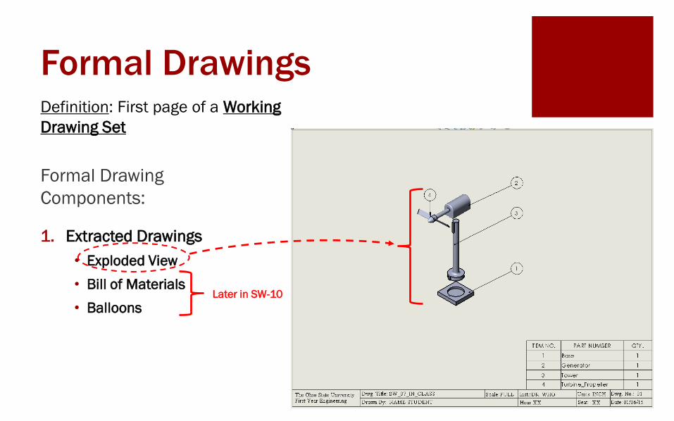
Formal Drawings
Formal Drawing
Components:
1. Extracted Drawings
• Exploded View
• Bill of Materials
• Balloons
Definition: First page of a Working
Drawing Set
Later in SW-10
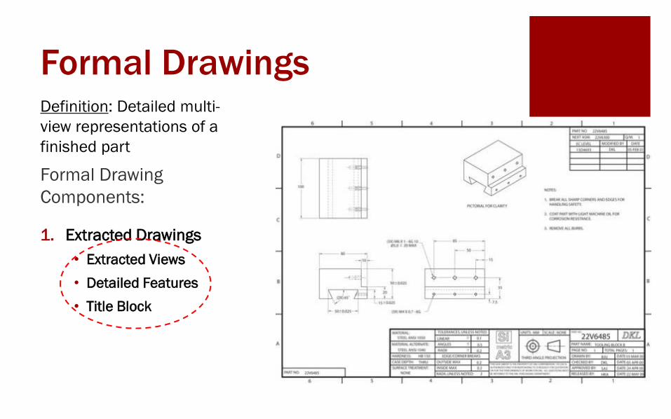
Formal Drawings
Formal Drawing
Components:
1. Extracted Drawings
• Extracted Views
• Detailed Features
• Title Block
Definition: Detailed multi-
view representations of a
finished part
Exploded View
ENGR 1182
SolidWorks 08
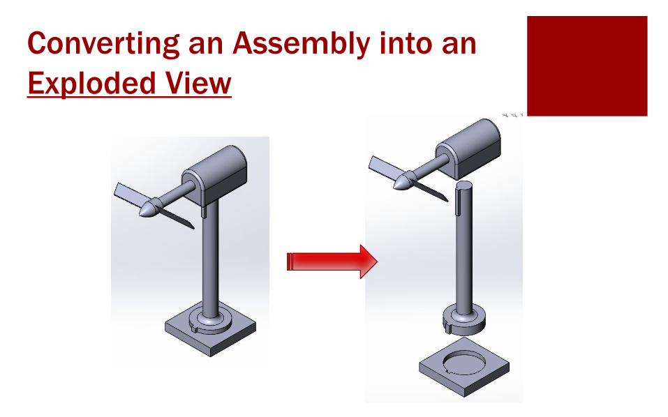
Converting an Assembly into an
Exploded View
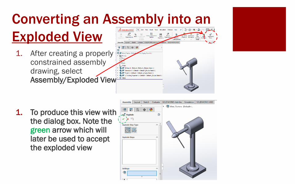
Converting an Assembly into an
Exploded View1. After creating a properly
constrained assembly drawing, select Assembly/Exploded View
1. To produce this view with the dialog box. Note the green arrow which will later be used to accept the exploded view
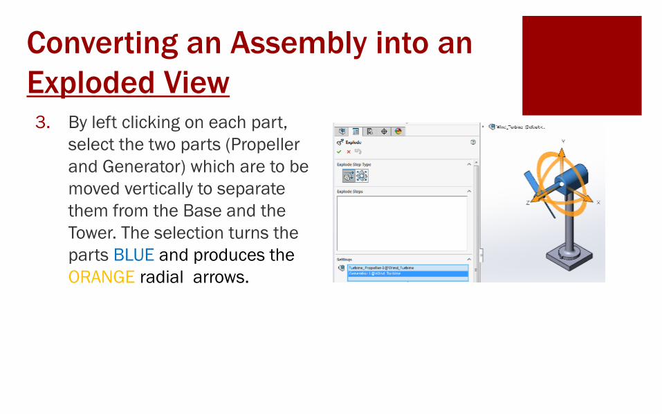
Converting an Assembly into an
Exploded View3. By left clicking on each part,
select the two parts (Propeller
and Generator) which are to be
moved vertically to separate
them from the Base and the
Tower. The selection turns the
parts BLUE and produces the
ORANGE radial arrows.
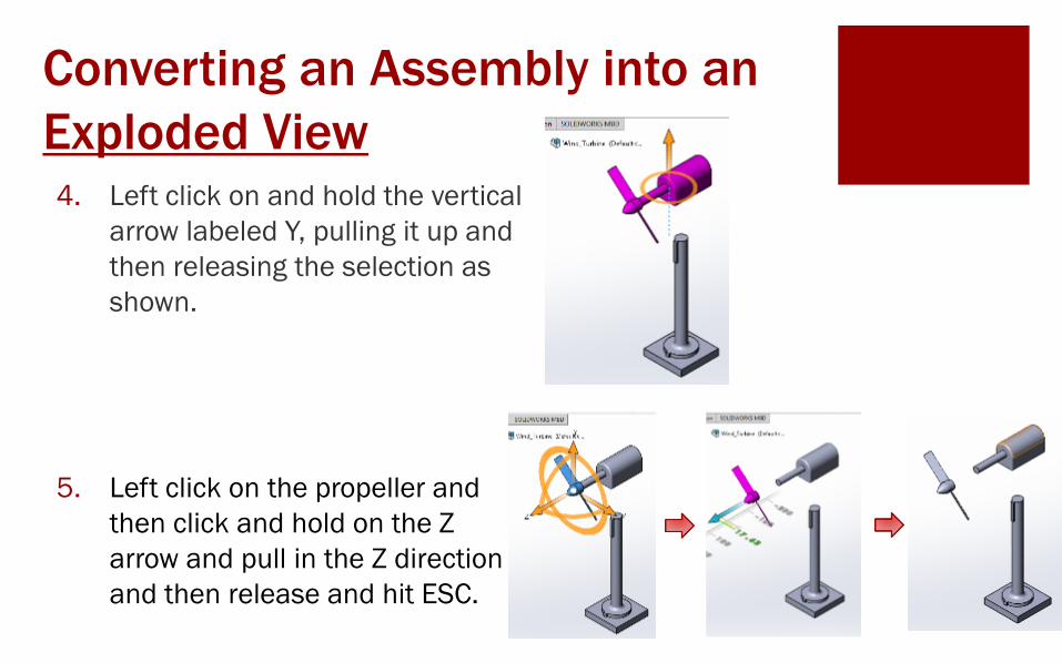
Converting an Assembly into an
Exploded View4. Left click on and hold the vertical
arrow labeled Y, pulling it up and
then releasing the selection as
shown.
5. Left click on the propeller and
then click and hold on the Z
arrow and pull in the Z direction
and then release and hit ESC.
Converting an Assembly into an
Exploded View
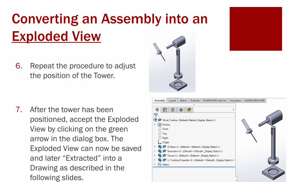
6. Repeat the procedure to adjust
the position of the Tower.
7. After the tower has been
positioned, accept the Exploded
View by clicking on the green
arrow in the dialog box. The
Exploded View can now be saved
and later “Extracted” into a
Drawing as described in the
following slides.
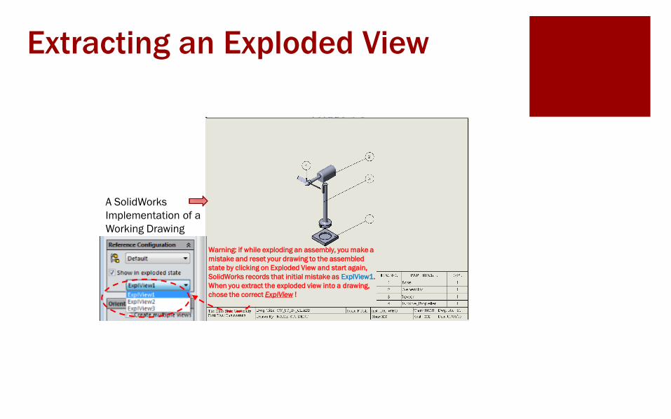
A SolidWorks
Implementation of a
Working Drawing
Warning: if while exploding an assembly, you make a
mistake and reset your drawing to the assembled
state by clicking on Exploded View and start again,
SolidWorks records that initial mistake as ExplView1.
When you extract the exploded view into a drawing,
chose the correct ExplView !
Extracting an Exploded View
Extracting Drawings
ENGR 1182
SolidWorks 08
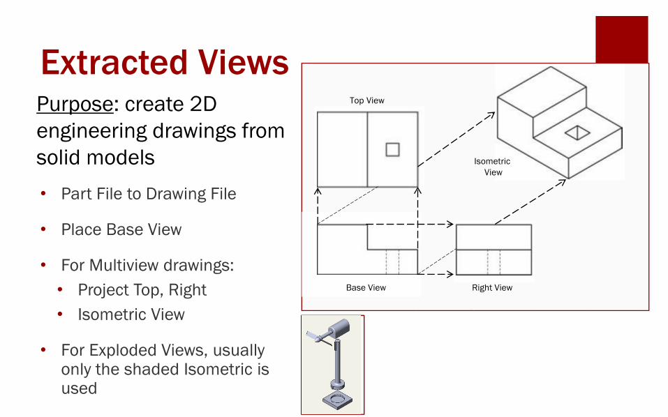
Extracted ViewsPurpose: create 2D
engineering drawings from
solid models
Base View Right View
Top View
Isometric
View
• Part File to Drawing File
• Place Base View
• For Multiview drawings:
• Project Top, Right
• Isometric View
• For Exploded Views, usually only the shaded Isometric is used
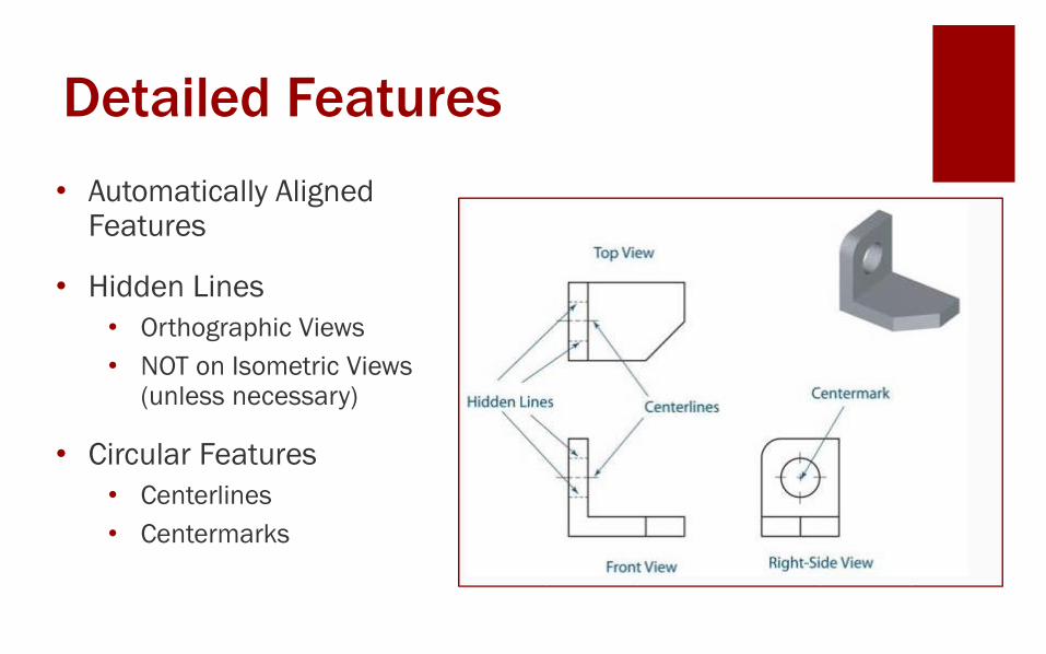
Detailed Features
• Automatically Aligned Features
• Hidden Lines
• Orthographic Views
• NOT on Isometric Views (unless necessary)
• Circular Features
• Centerlines
• Centermarks
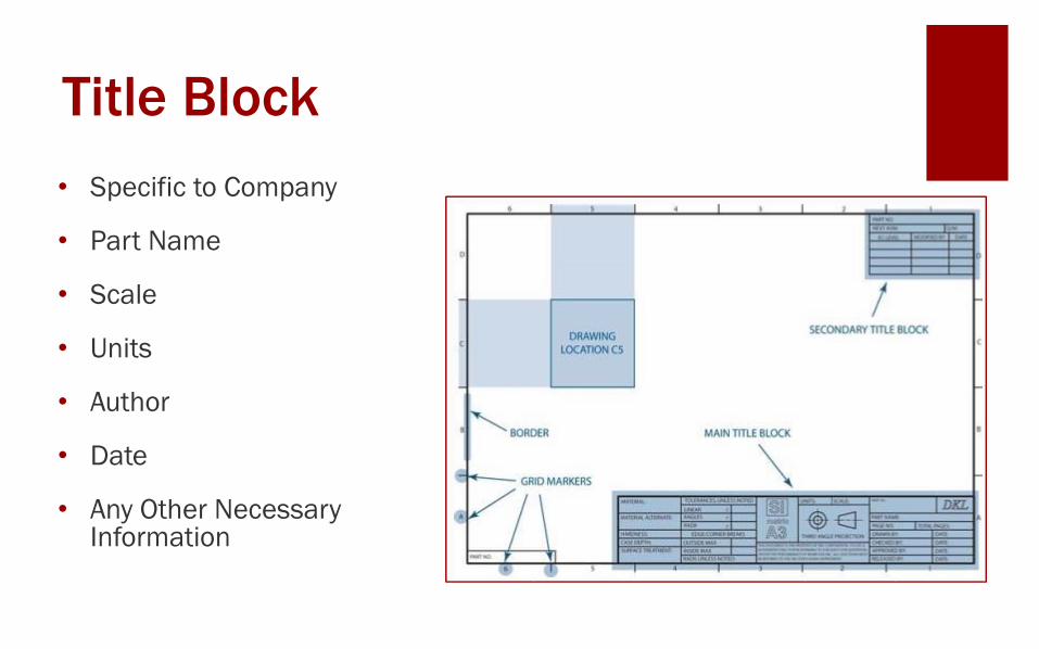
Title Block
• Specific to Company
• Part Name
• Scale
• Units
• Author
• Date
• Any Other Necessary Information
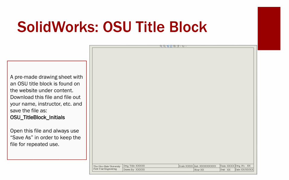
SolidWorks: OSU Title Block
A pre-made drawing sheet with
an OSU title block is found on
the website under content.
Download this file and file out
your name, instructor, etc. and
save the file as:
OSU_TitleBlock_Initials
Open this file and always use
“Save As” in order to keep the
file for repeated use.
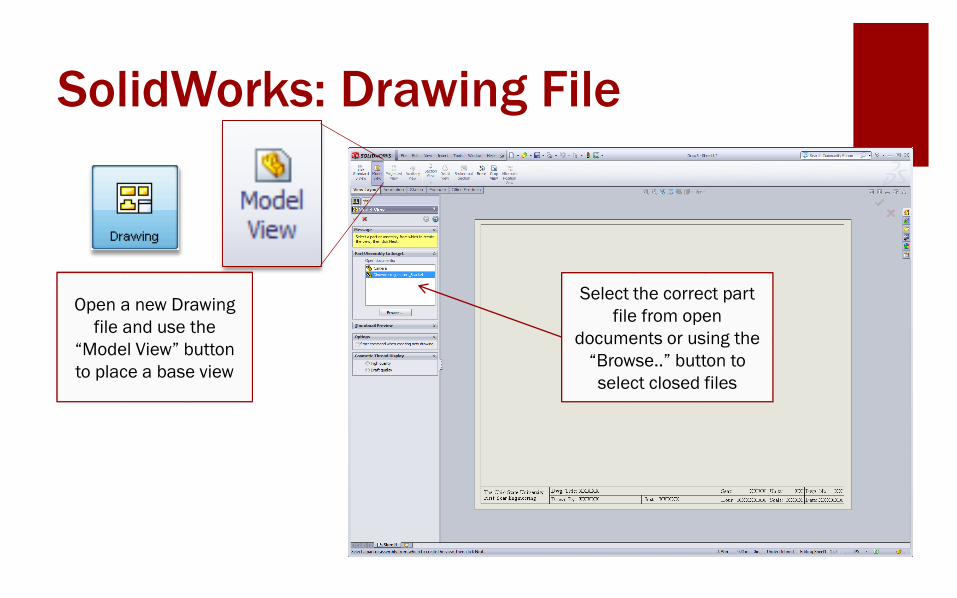
SolidWorks: Drawing File
Select the correct part
file from open
documents or using the
“Browse..” button to
select closed files
Open a new Drawing
file and use the
“Model View” button
to place a base view
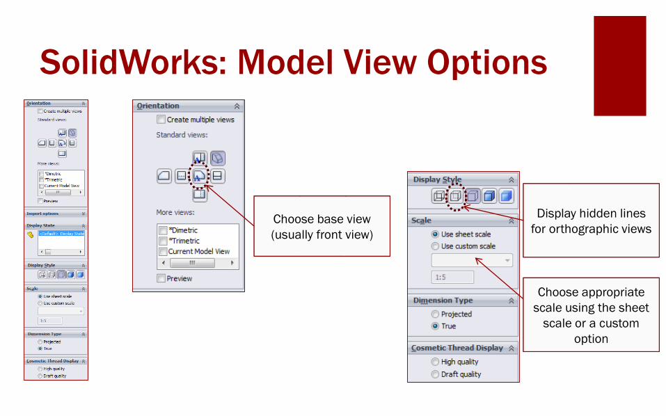
SolidWorks: Model View Options
Choose base view
(usually front view)
Display hidden lines
for orthographic views
Choose appropriate
scale using the sheet
scale or a custom
option
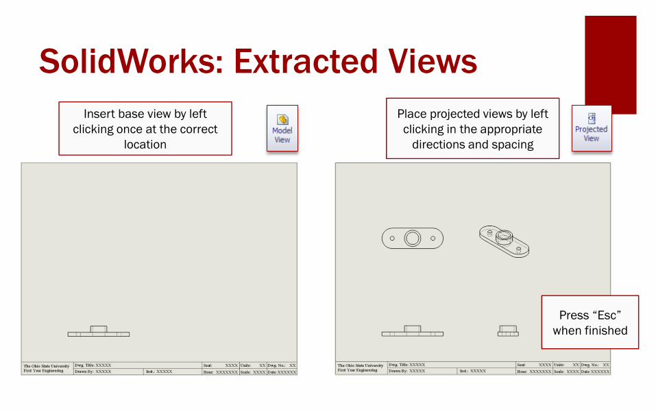
SolidWorks: Extracted Views
Insert base view by left
clicking once at the correct
location
Place projected views by left
clicking in the appropriate
directions and spacing
Press “Esc”
when finished
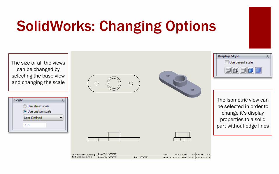
SolidWorks: Changing Options
The size of all the views
can be changed by
selecting the base view
and changing the scale
The isometric view can
be selected in order to
change it’s display
properties to a solid
part without edge lines
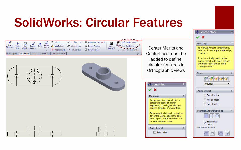
SolidWorks: Circular Features
Center Marks and
Centerlines must be
added to define
circular features in
Orthographic views
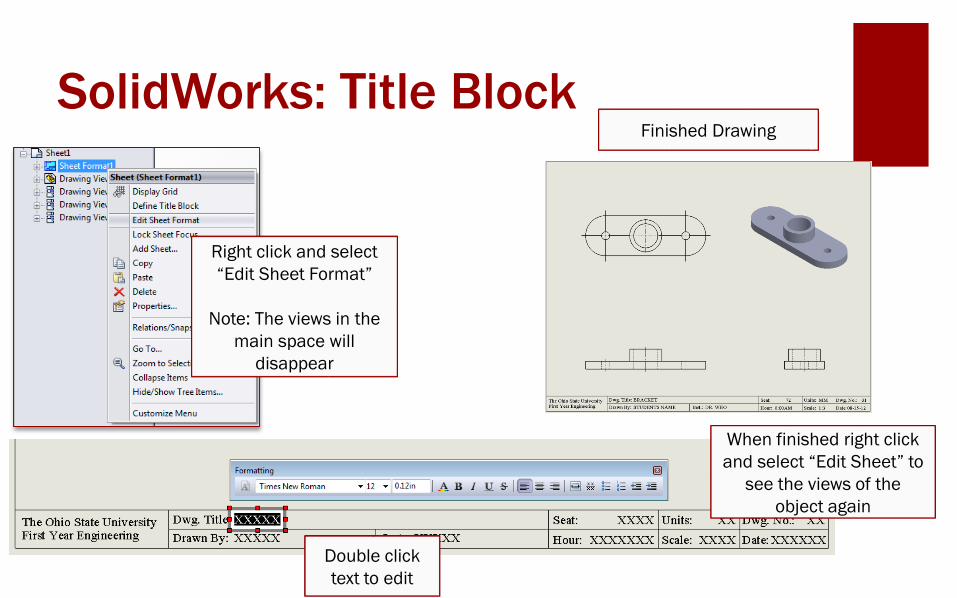
SolidWorks: Title Block
Right click and select
“Edit Sheet Format”
Note: The views in the
main space will
disappear
Double click
text to edit
Finished Drawing
When finished right click
and select “Edit Sheet” to
see the views of the
object again
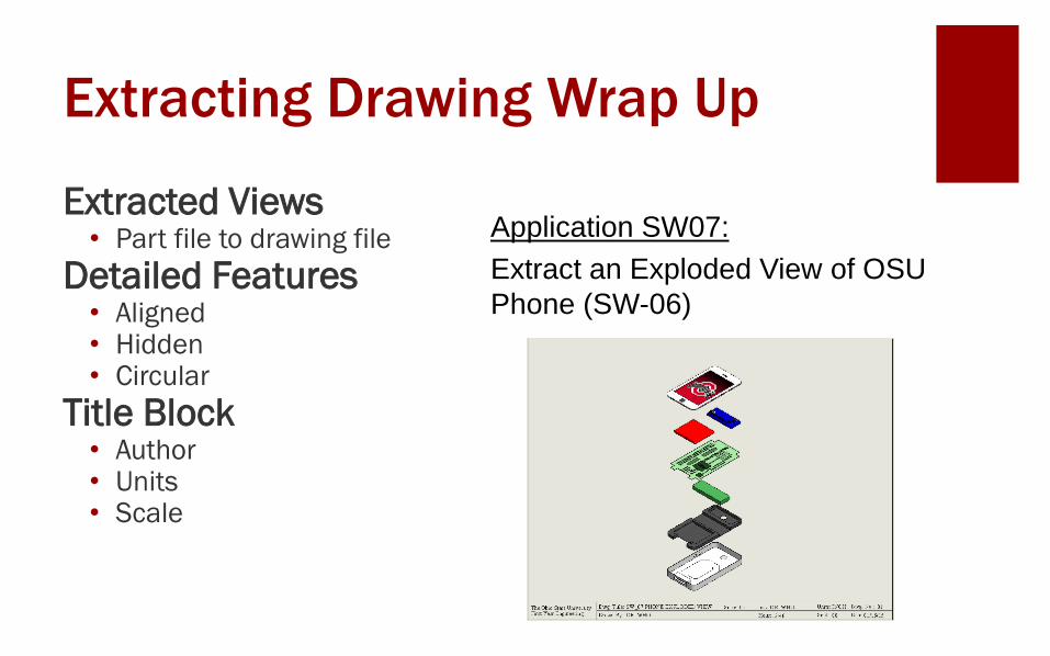
Extracting Drawing Wrap Up
Extracted Views• Part file to drawing file
Detailed Features• Aligned • Hidden• Circular
Title Block• Author• Units• Scale
Application SW07:
Extract an Exploded View of OSU
Phone (SW-06)
Important Takeaways
Extracted drawings are used to show
3D parts as 2D drawings or to create
an Exploded View as part of a set of
Working Drawing.
Titles blocks are used for identification
and informative purposes.
.
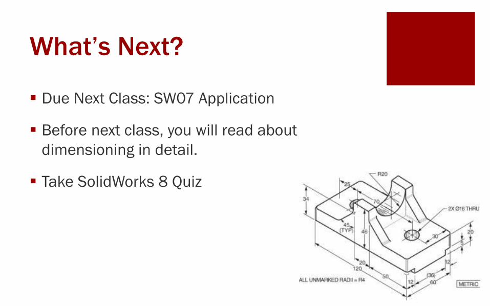
What’s Next?
Due Next Class: SW07 Application
Before next class, you will read about
dimensioning in detail.
Take SolidWorks 8 Quiz