Embed Size (px)
Citation preview
IEEE TRANSACTIONS ON VISUALIZATION AND COMPUTER GRAPHICS, VOL. 12, NO. 5, SEPTEMBER/OCTOBER 2006
Exploded Views for Volume Data
Stefan Bruckner and M. Eduard Groller, Member, IEEE Computer Society
Abstract—Exploded views are an illustration technique where an object is partitioned into several segments. These segments aredisplaced to reveal otherwise hidden detail. In this paper we apply the concept of exploded views to volumetric data in order to solvethe general problem of occlusion. In many cases an object of interest is occluded by other structures. While transparency or cutawayscan be used to reveal a focus object, these techniques remove parts of the context information. Exploded views, on the other hand, donot suffer from this drawback. Our approach employs a force-based model: the volume is divided into a part configuration controlledby a number of forces and constraints. The focus object exerts an explosion force causing the parts to arrange according to thegiven constraints. We show that this novel and flexible approach allows for a wide variety of explosion-based visualizations includingview-dependent explosions. Furthermore, we present a high-quality GPU-based volume ray casting algorithm for exploded viewswhich allows rendering and interaction at several frames per second.
Index Terms—Illustrative visualization, exploded views, volume rendering.
F
1 INTRODUCTION
Occlusion is an important problem when rendering truly three-dimensional information in scientific visualization, such as, for ex-ample, medical data acquired from computer tomography. Becauseof occlusion, normally not all of the data can be shown concurrently.Frequently, the user wants to examine an object of interest within thevolumetric data set. In many cases depicting this focus object on itsown is not sufficient – the user is interested in exploring it within thecontext of the whole data set. To solve the problem of occlusion thecontext can be assigned a different - more sparse - visual representa-tion, for example by reducing its opacity. This adjustment can even beperformed locally, so the representation only changes for those partsof the context which actually occlude the focus [32, 33, 2]. In illus-trations, cutaways and ghosting techniques are used for this purpose.However, the drawback of these approaches is that parts of the contextinformation are still removed or suppressed. If it is instructive to retainthe context even when it occludes the focus structure, illustrators oftenemploy exploded views.
Basically, in an exploded view the object is decomposed into sev-eral parts which are displaced so that internal details are visible (seeFigure 1). This does not only give an unobstructed view on the fo-cus but also potentially reveals other interesting information, such ascross-sections of the split object. The advantage of exploded views isthat they simultaneously convey the global structure of the depictedobject, the details of individual components, and the local relation-ships among them.
The contribution of this paper is a new technique for generating ex-ploded views based on a three-dimensional force-directed layout. Wepresent an approach that is capable of producing high quality explodeddepictions of volume data at interactive frame rates. One applicationof our framework is the generation of highly detailed anatomic illus-trations from scanned data (see Figure 2 and Figure 3).
The paper is structured as follows: In Section 2 we discuss relatedwork. Section 3 presents our approach for the generation of explodedviews from volumetric data sets. In Section 4 we detail our renderingalgorithm. The paper is concluded in Section 5.
• Stefan Bruckner and M. Eduard Groller are with the Institute of Computer
Graphics and Algorithms, Vienna University of Technology, E-mail:
{bruckner|groeller}@cg.tuwien.ac.at.
Manuscript received 1 March 2006; accepted 1 August 2006; posted online 6
November 2006.
For information on obtaining reprints of this article, please send e-mail to:
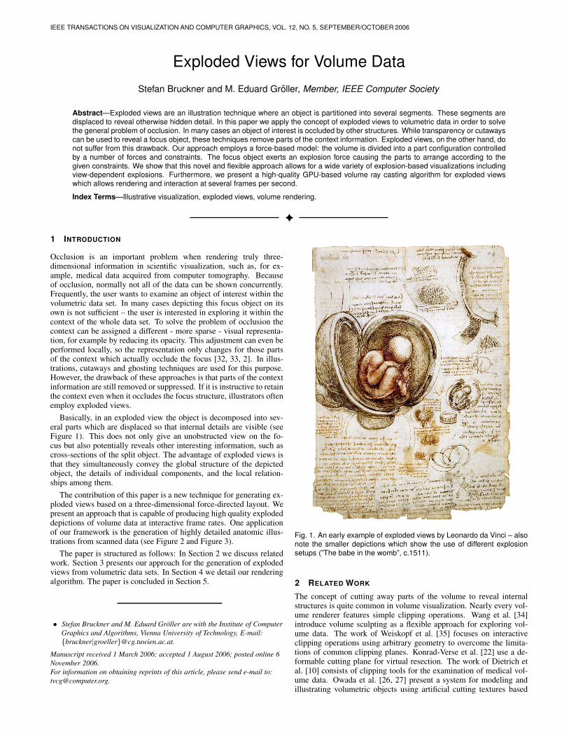
Fig. 1. An early example of exploded views by Leonardo da Vinci – alsonote the smaller depictions which show the use of different explosionsetups (”The babe in the womb”, c.1511).
2 RELATED WORK
The concept of cutting away parts of the volume to reveal internalstructures is quite common in volume visualization. Nearly every vol-ume renderer features simple clipping operations. Wang et al. [34]introduce volume sculpting as a flexible approach for exploring vol-ume data. The work of Weiskopf et al. [35] focuses on interactiveclipping operations using arbitrary geometry to overcome the limita-tions of common clipping planes. Konrad-Verse et al. [22] use a de-formable cutting plane for virtual resection. The work of Dietrich etal. [10] consists of clipping tools for the examination of medical vol-ume data. Owada et al. [26, 27] present a system for modeling andillustrating volumetric objects using artificial cutting textures based
IEEE TRANSACTIONS ON VISUALIZATION AND COMPUTER GRAPHICS, VOL. 12, NO. 5, SEPTEMBER/OCTOBER 2006
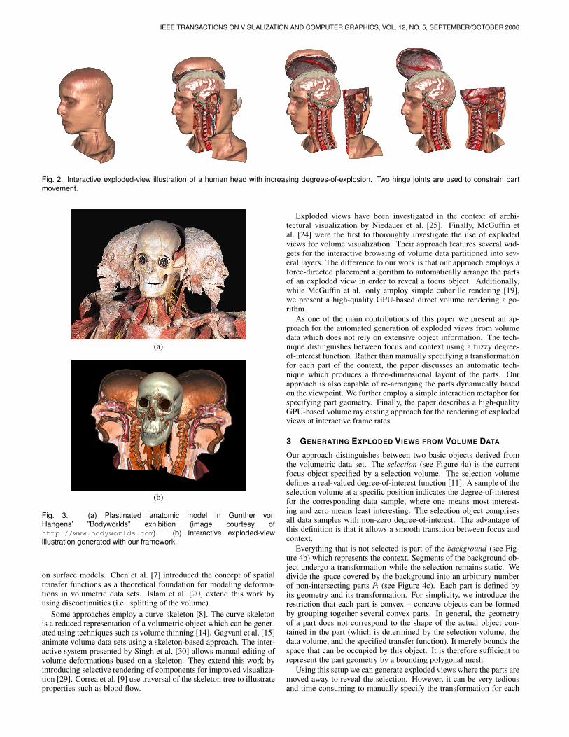
Fig. 2. Interactive exploded-view illustration of a human head with increasing degrees-of-explosion. Two hinge joints are used to constrain partmovement.
(a)
(b)
Fig. 3. (a) Plastinated anatomic model in Gunther vonHangens’ ”Bodyworlds” exhibition (image courtesy ofhttp://www.bodyworlds.com). (b) Interactive exploded-viewillustration generated with our framework.
on surface models. Chen et al. [7] introduced the concept of spatialtransfer functions as a theoretical foundation for modeling deforma-tions in volumetric data sets. Islam et al. [20] extend this work byusing discontinuities (i.e., splitting of the volume).
Some approaches employ a curve-skeleton [8]. The curve-skeletonis a reduced representation of a volumetric object which can be gener-ated using techniques such as volume thinning [14]. Gagvani et al. [15]animate volume data sets using a skeleton-based approach. The inter-active system presented by Singh et al. [30] allows manual editing ofvolume deformations based on a skeleton. They extend this work byintroducing selective rendering of components for improved visualiza-tion [29]. Correa et al. [9] use traversal of the skeleton tree to illustrateproperties such as blood flow.
Exploded views have been investigated in the context of archi-tectural visualization by Niedauer et al. [25]. Finally, McGuffin etal. [24] were the first to thoroughly investigate the use of explodedviews for volume visualization. Their approach features several wid-gets for the interactive browsing of volume data partitioned into sev-eral layers. The difference to our work is that our approach employs aforce-directed placement algorithm to automatically arrange the partsof an exploded view in order to reveal a focus object. Additionally,while McGuffin et al. only employ simple cuberille rendering [19],we present a high-quality GPU-based direct volume rendering algo-rithm.
As one of the main contributions of this paper we present an ap-proach for the automated generation of exploded views from volumedata which does not rely on extensive object information. The tech-nique distinguishes between focus and context using a fuzzy degree-of-interest function. Rather than manually specifying a transformationfor each part of the context, the paper discusses an automatic tech-nique which produces a three-dimensional layout of the parts. Ourapproach is also capable of re-arranging the parts dynamically basedon the viewpoint. We further employ a simple interaction metaphor forspecifying part geometry. Finally, the paper describes a high-qualityGPU-based volume ray casting approach for the rendering of explodedviews at interactive frame rates.
3 GENERATING EXPLODED VIEWS FROM VOLUME DATA
Our approach distinguishes between two basic objects derived fromthe volumetric data set. The selection (see Figure 4a) is the currentfocus object specified by a selection volume. The selection volumedefines a real-valued degree-of-interest function [11]. A sample of theselection volume at a specific position indicates the degree-of-interestfor the corresponding data sample, where one means most interest-ing and zero means least interesting. The selection object comprisesall data samples with non-zero degree-of-interest. The advantage ofthis definition is that it allows a smooth transition between focus andcontext.
Everything that is not selected is part of the background (see Fig-ure 4b) which represents the context. Segments of the background ob-ject undergo a transformation while the selection remains static. Wedivide the space covered by the background into an arbitrary numberof non-intersecting parts Pi (see Figure 4c). Each part is defined byits geometry and its transformation. For simplicity, we introduce therestriction that each part is convex – concave objects can be formedby grouping together several convex parts. In general, the geometryof a part does not correspond to the shape of the actual object con-tained in the part (which is determined by the selection volume, thedata volume, and the specified transfer function). It merely bounds thespace that can be occupied by this object. It is therefore sufficient torepresent the part geometry by a bounding polygonal mesh.
Using this setup we can generate exploded views where the parts aremoved away to reveal the selection. However, it can be very tediousand time-consuming to manually specify the transformation for each
BRUCKNER et al.: EXPLODED VIEWS FOR VOLUME DATA
(a) (b) (c)
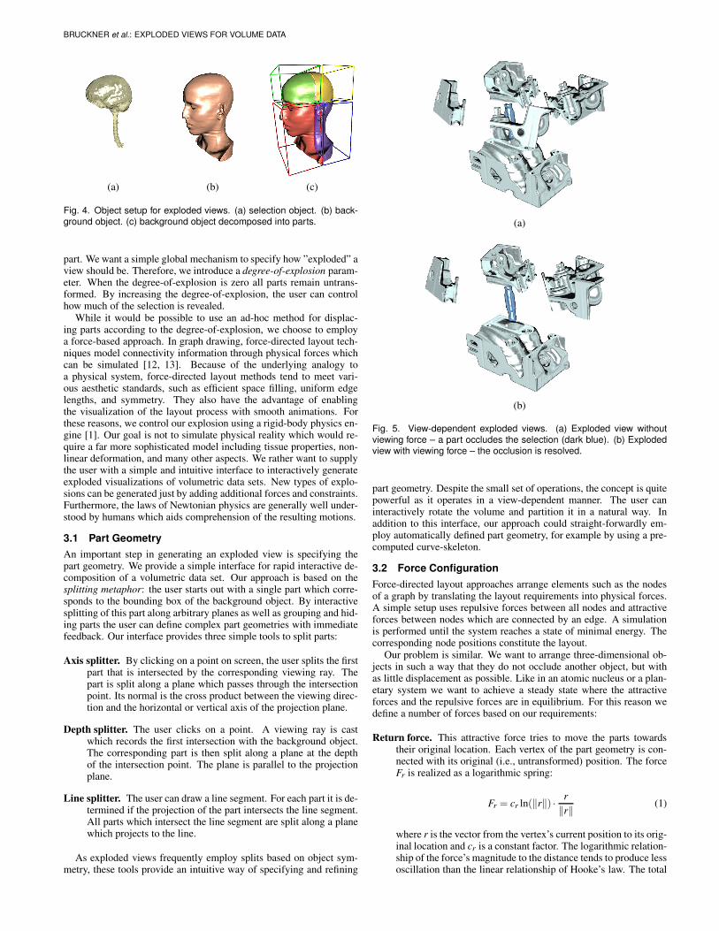
Fig. 4. Object setup for exploded views. (a) selection object. (b) back-ground object. (c) background object decomposed into parts.
part. We want a simple global mechanism to specify how ”exploded” aview should be. Therefore, we introduce a degree-of-explosion param-eter. When the degree-of-explosion is zero all parts remain untrans-formed. By increasing the degree-of-explosion, the user can controlhow much of the selection is revealed.
While it would be possible to use an ad-hoc method for displac-ing parts according to the degree-of-explosion, we choose to employa force-based approach. In graph drawing, force-directed layout tech-niques model connectivity information through physical forces whichcan be simulated [12, 13]. Because of the underlying analogy toa physical system, force-directed layout methods tend to meet vari-ous aesthetic standards, such as efficient space filling, uniform edgelengths, and symmetry. They also have the advantage of enablingthe visualization of the layout process with smooth animations. Forthese reasons, we control our explosion using a rigid-body physics en-gine [1]. Our goal is not to simulate physical reality which would re-quire a far more sophisticated model including tissue properties, non-linear deformation, and many other aspects. We rather want to supplythe user with a simple and intuitive interface to interactively generateexploded visualizations of volumetric data sets. New types of explo-sions can be generated just by adding additional forces and constraints.Furthermore, the laws of Newtonian physics are generally well under-stood by humans which aids comprehension of the resulting motions.
3.1 Part Geometry
An important step in generating an exploded view is specifying thepart geometry. We provide a simple interface for rapid interactive de-composition of a volumetric data set. Our approach is based on thesplitting metaphor: the user starts out with a single part which corre-sponds to the bounding box of the background object. By interactivesplitting of this part along arbitrary planes as well as grouping and hid-ing parts the user can define complex part geometries with immediatefeedback. Our interface provides three simple tools to split parts:
Axis splitter. By clicking on a point on screen, the user splits the firstpart that is intersected by the corresponding viewing ray. Thepart is split along a plane which passes through the intersectionpoint. Its normal is the cross product between the viewing direc-tion and the horizontal or vertical axis of the projection plane.
Depth splitter. The user clicks on a point. A viewing ray is castwhich records the first intersection with the background object.The corresponding part is then split along a plane at the depthof the intersection point. The plane is parallel to the projectionplane.
Line splitter. The user can draw a line segment. For each part it is de-termined if the projection of the part intersects the line segment.All parts which intersect the line segment are split along a planewhich projects to the line.
As exploded views frequently employ splits based on object sym-metry, these tools provide an intuitive way of specifying and refining
(a)
(b)
Fig. 5. View-dependent exploded views. (a) Exploded view withoutviewing force – a part occludes the selection (dark blue). (b) Explodedview with viewing force – the occlusion is resolved.
part geometry. Despite the small set of operations, the concept is quitepowerful as it operates in a view-dependent manner. The user caninteractively rotate the volume and partition it in a natural way. Inaddition to this interface, our approach could straight-forwardly em-ploy automatically defined part geometry, for example by using a pre-computed curve-skeleton.
3.2 Force Configuration
Force-directed layout approaches arrange elements such as the nodesof a graph by translating the layout requirements into physical forces.A simple setup uses repulsive forces between all nodes and attractiveforces between nodes which are connected by an edge. A simulationis performed until the system reaches a state of minimal energy. Thecorresponding node positions constitute the layout.
Our problem is similar. We want to arrange three-dimensional ob-jects in such a way that they do not occlude another object, but withas little displacement as possible. Like in an atomic nucleus or a plan-etary system we want to achieve a steady state where the attractiveforces and the repulsive forces are in equilibrium. For this reason wedefine a number of forces based on our requirements:
Return force. This attractive force tries to move the parts towardstheir original location. Each vertex of the part geometry is con-nected with its original (i.e., untransformed) position. The forceFr is realized as a logarithmic spring:
Fr = cr ln(‖r‖) ·r
‖r‖(1)
where r is the vector from the vertex’s current position to its orig-inal location and cr is a constant factor. The logarithmic relation-ship of the force’s magnitude to the distance tends to produce lessoscillation than the linear relationship of Hooke’s law. The total
IEEE TRANSACTIONS ON VISUALIZATION AND COMPUTER GRAPHICS, VOL. 12, NO. 5, SEPTEMBER/OCTOBER 2006
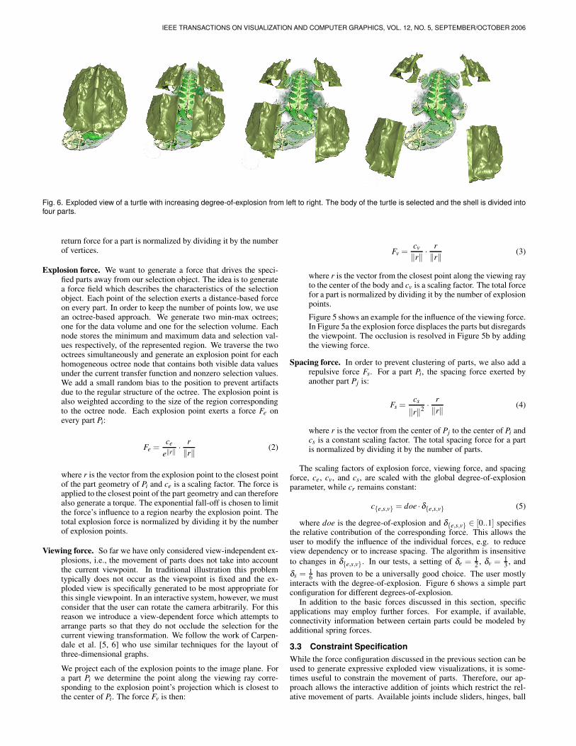
Fig. 6. Exploded view of a turtle with increasing degree-of-explosion from left to right. The body of the turtle is selected and the shell is divided intofour parts.
return force for a part is normalized by dividing it by the numberof vertices.
Explosion force. We want to generate a force that drives the speci-fied parts away from our selection object. The idea is to generatea force field which describes the characteristics of the selectionobject. Each point of the selection exerts a distance-based forceon every part. In order to keep the number of points low, we usean octree-based approach. We generate two min-max octrees;one for the data volume and one for the selection volume. Eachnode stores the minimum and maximum data and selection val-ues respectively, of the represented region. We traverse the twooctrees simultaneously and generate an explosion point for eachhomogeneous octree node that contains both visible data valuesunder the current transfer function and nonzero selection values.We add a small random bias to the position to prevent artifactsdue to the regular structure of the octree. The explosion point isalso weighted according to the size of the region correspondingto the octree node. Each explosion point exerts a force Fe onevery part Pi:
Fe =ce
e‖r‖·
r
‖r‖(2)
where r is the vector from the explosion point to the closest pointof the part geometry of Pi and ce is a scaling factor. The force isapplied to the closest point of the part geometry and can thereforealso generate a torque. The exponential fall-off is chosen to limitthe force’s influence to a region nearby the explosion point. Thetotal explosion force is normalized by dividing it by the numberof explosion points.
Viewing force. So far we have only considered view-independent ex-plosions, i.e., the movement of parts does not take into accountthe current viewpoint. In traditional illustration this problemtypically does not occur as the viewpoint is fixed and the ex-ploded view is specifically generated to be most appropriate forthis single viewpoint. In an interactive system, however, we mustconsider that the user can rotate the camera arbitrarily. For thisreason we introduce a view-dependent force which attempts toarrange parts so that they do not occlude the selection for thecurrent viewing transformation. We follow the work of Carpen-dale et al. [5, 6] who use similar techniques for the layout ofthree-dimensional graphs.
We project each of the explosion points to the image plane. Fora part Pi we determine the point along the viewing ray corre-sponding to the explosion point’s projection which is closest tothe center of Pi. The force Fv is then:
Fv =cv
‖r‖·
r
‖r‖(3)
where r is the vector from the closest point along the viewing rayto the center of the body and cv is a scaling factor. The total forcefor a part is normalized by dividing it by the number of explosionpoints.
Figure 5 shows an example for the influence of the viewing force.In Figure 5a the explosion force displaces the parts but disregardsthe viewpoint. The occlusion is resolved in Figure 5b by addingthe viewing force.
Spacing force. In order to prevent clustering of parts, we also add arepulsive force Fs. For a part Pi, the spacing force exerted byanother part Pj is:
Fs =cs
‖r‖2·
r
‖r‖(4)
where r is the vector from the center of Pj to the center of Pi andcs is a constant scaling factor. The total spacing force for a partis normalized by dividing it by the number of parts.
The scaling factors of explosion force, viewing force, and spacingforce, ce, cv, and cs, are scaled with the global degree-of-explosionparameter, while cr remains constant:
c{e,s,v} = doe ·δ{e,s,v} (5)
where doe is the degree-of-explosion and δ{e,s,v} ∈ [0..1] specifiesthe relative contribution of the corresponding force. This allows theuser to modify the influence of the individual forces, e.g. to reduceview dependency or to increase spacing. The algorithm is insensitive
to changes in δ{e,s,v}. In our tests, a setting of δe = 12 , δv = 1
3 , and
δs = 16 has proven to be a universally good choice. The user mostly
interacts with the degree-of-explosion. Figure 6 shows a simple partconfiguration for different degrees-of-explosion.
In addition to the basic forces discussed in this section, specificapplications may employ further forces. For example, if available,connectivity information between certain parts could be modeled byadditional spring forces.
3.3 Constraint Specification
While the force configuration discussed in the previous section can beused to generate expressive exploded view visualizations, it is some-times useful to constrain the movement of parts. Therefore, our ap-proach allows the interactive addition of joints which restrict the rel-ative movement of parts. Available joints include sliders, hinges, ball
BRUCKNER et al.: EXPLODED VIEWS FOR VOLUME DATA
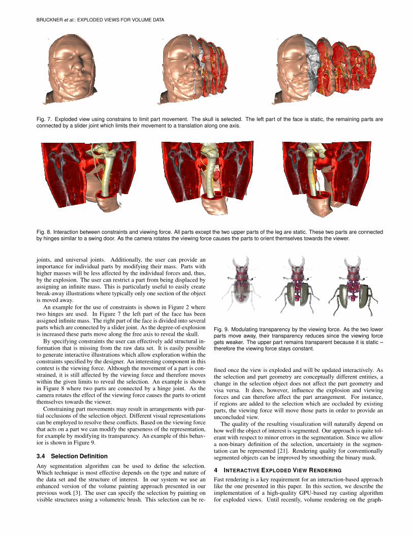
Fig. 7. Exploded view using constrains to limit part movement. The skull is selected. The left part of the face is static, the remaining parts areconnected by a slider joint which limits their movement to a translation along one axis.
Fig. 8. Interaction between constraints and viewing force. All parts except the two upper parts of the leg are static. These two parts are connectedby hinges similar to a swing door. As the camera rotates the viewing force causes the parts to orient themselves towards the viewer.
joints, and universal joints. Additionally, the user can provide animportance for individual parts by modifying their mass. Parts withhigher masses will be less affected by the individual forces and, thus,by the explosion. The user can restrict a part from being displaced byassigning an infinite mass. This is particularly useful to easily createbreak-away illustrations where typically only one section of the objectis moved away.
An example for the use of constraints is shown in Figure 2 wheretwo hinges are used. In Figure 7 the left part of the face has beenassigned infinite mass. The right part of the face is divided into severalparts which are connected by a slider joint. As the degree-of-explosionis increased these parts move along the free axis to reveal the skull.
By specifying constraints the user can effectively add structural in-formation that is missing from the raw data set. It is easily possibleto generate interactive illustrations which allow exploration within theconstraints specified by the designer. An interesting component in thiscontext is the viewing force. Although the movement of a part is con-strained, it is still affected by the viewing force and therefore moveswithin the given limits to reveal the selection. An example is shownin Figure 8 where two parts are connected by a hinge joint. As thecamera rotates the effect of the viewing force causes the parts to orientthemselves towards the viewer.
Constraining part movements may result in arrangements with par-tial occlusions of the selection object. Different visual representationscan be employed to resolve these conflicts. Based on the viewing forcethat acts on a part we can modify the sparseness of the representation,for example by modifying its transparency. An example of this behav-ior is shown in Figure 9.
3.4 Selection Definition
Any segmentation algorithm can be used to define the selection.Which technique is most effective depends on the type and nature ofthe data set and the structure of interest. In our system we use anenhanced version of the volume painting approach presented in ourprevious work [3]. The user can specify the selection by painting onvisible structures using a volumetric brush. This selection can be re-
Fig. 9. Modulating transparency by the viewing force. As the two lowerparts move away, their transparency reduces since the viewing forcegets weaker. The upper part remains transparent because it is static –therefore the viewing force stays constant.
fined once the view is exploded and will be updated interactively. Asthe selection and part geometry are conceptually different entities, achange in the selection object does not affect the part geometry andvisa versa. It does, however, influence the explosion and viewingforces and can therefore affect the part arrangement. For instance,if regions are added to the selection which are occluded by existingparts, the viewing force will move those parts in order to provide anunconcluded view.
The quality of the resulting visualization will naturally depend onhow well the object of interest is segmented. Our approach is quite tol-erant with respect to minor errors in the segmentation. Since we allowa non-binary definition of the selection, uncertainty in the segmen-tation can be represented [21]. Rendering quality for conventionallysegmented objects can be improved by smoothing the binary mask.
4 INTERACTIVE EXPLODED VIEW RENDERING
Fast rendering is a key requirement for an interaction-based approachlike the one presented in this paper. In this section, we describe theimplementation of a high-quality GPU-based ray casting algorithmfor exploded views. Until recently, volume rendering on the graph-
IEEE TRANSACTIONS ON VISUALIZATION AND COMPUTER GRAPHICS, VOL. 12, NO. 5, SEPTEMBER/OCTOBER 2006
Algorithm 1 Basic rendering algorithm
perform visibility sorting of the partsgenerate initial entry and exit pointsperform initial ray castingfor all parts Pi in front-to-back order do
generate entry and exit points for Pi (see Section 4.1)perform ray casting for Pi (see Section 4.2)
end for
ics hardware was only possible using a multi-pass approach [23]. Thishas changed with the advent of conditional loops and dynamic branch-ing in shaders. Now it is possible to implement a fragment programwhich completely traverses a ray [31]. Apart from the quality improve-ments, this allows for common acceleration techniques like early raytermination and empty-space skipping [18, 28].
For rendering an exploded view we need to be able to render a vol-umetric data set consisting of a background and a selection object.The background object is decomposed into several non-intersectingconvex parts which can have arbitrary affine transformations. The se-lection object also has its assigned transformation and can intersectany part. Furthermore, we want to support empty space skipping andearly ray termination. Therefore we assume that we have geometryenclosing the visible volume under the current transfer function forboth background and selection object. The use of this kind of bound-ing structures for empty space skipping is very common in volumerendering. They are frequently based on hierarchical data structures.In our implementation, we use min-max octrees for both data volumeand selection volume.
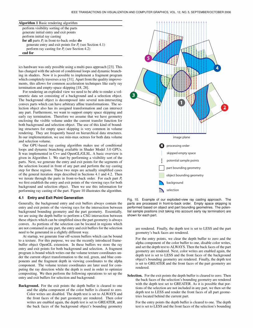
Our GPU-based ray casting algorithm makes use of conditionalloops and dynamic branching available in Shader Model 3.0 GPUs.It was implemented in C++ and OpenGL/GLSL. A basic overview isgiven in Algorithm 1. We start by performing a visibility sort of theparts. Next, we generate the entry and exit points for the segments ofthe selection located in front of any part and perform the ray castingstep for these regions. These two steps are actually simplified casesof the general iteration steps described in Sections 4.1 and 4.2. Thenwe iterate through the parts in front-to-back order. For each part Pi
we first establish the entry and exit points of the viewing rays for bothbackground and selection object. Then we use this information forperforming ray casting of the part. Figure 10 illustrates the algorithm.
4.1 Entry and Exit Point Generation
Generally, the background entry and exit buffers always contain theentry and exit points of the viewing rays for the intersection betweenbackground bounding geometry and the part geometry. Essentially,we are using the depth buffer to perform a CSG intersection betweenthese objects which can be simplified since the part geometry is alwaysconvex. As portions of the selection can be located in regions whichare not contained in any part, the entry and exit buffers for the selectionneed to be generated in a slightly different way.
At startup, we generate four off-screen buffers which can be boundto a texture. For this purpose, we use the recently introduced frame-buffer object OpenGL extension. In these buffers we store the rayentry and exit points for both background and selection. A fragmentprogram is bound which writes out the volume texture coordinates un-der the current object transformation to the red, green, and blue com-ponents and the fragment depth in viewing coordinates to the alphacomponent. The volume texture coordinates are later used for com-puting the ray direction while the depth is used in order to optimizecompositing. We then perform the following operations to set up theentry and exit buffers for selection and background:
Background. For the exit points the depth buffer is cleared to oneand the alpha component of the color buffer is cleared to zero.Color writes are disabled. The depth test is set to ALWAYS andthe front faces of the part geometry are rendered. Then colorwrites are enabled again, the depth test is set to GREATER, andthe back faces of the background object’s bounding geometry
image plane
12
3
4
5
part bounding geometry
object bounding geometry
background
selection
N processing order
skipped empty space
potential sample points
Fig. 10. Example of our exploded-view ray casting approach. Theparts are processed in front-to-back order. Empty space skipping isperformed based on object and part bounding geometries. The poten-tial sample positions (not taking into account early ray termination) areshown for each part.
are rendered. Finally, the depth test is set to LESS and the partgeometry’s back faces are rendered.
For the entry points, we clear the depth buffer to zero and thealpha component of the color buffer to one, disable color writes,and set the depth test to ALWAYS. Then the back faces of the partgeometry are rendered. Next, color writes are enabled again, thedepth test is set to LESS and the front faces of the backgroundobject’s bounding geometry are rendered. Finally, the depth testis set to GREATER and the front faces of the part geometry arerendered.
Selection. For the exit points the depth buffer is cleared to zero. Thenthe back faces of the selection’s bounding geometry are renderedwith the depth test set to GREATER. As it is possible that por-tions of the selection are not included in any part, we then set thedepth test to LESS and render the front faces of all part geome-tries located behind the current part.
For the entry points the depth buffer is cleared to one. The depthtest is set to LESS and the front faces of the selection’s bounding

BRUCKNER et al.: EXPLODED VIEWS FOR VOLUME DATA
geometry are rendered. Then the depth test is set to GREATERand the front faces of the part’s bounding geometry are rendered.
We also need to handle the case when portions of the selection arelocated in front of all parts. This is done analogously to the iterationwith the only difference that the background does not have to be takeninto account for both the entry point determination and the ray castingstep. Thus, the selection entry points do not need to be clipped. Theselection exit points are clipped against all part geometries.
4.2 Multi-Object Ray Casting
The ray casting pass uses the entry and exits points for rendering thevolumetric object contained in the current part. The volume texturecoordinates stored in the red, green, and blue components of the en-try and exit point buffers are used to compute the ray direction. Thedepth value stored in the alpha component determines which objectsneed to be composited. If the intervals of background and selectiondo not overlap, they can be composited sequentially. If they overlap,however, multi-object compositing must be performed in the intersec-tion region, i.e., two rays have to be traversed simultaneously. Thecontributions of both objects at a sample point can be combined usingfusion functions [4], intersection transfer functions [3], or alternatingsampling [17].
The pseudocode given in Algorithm 2 shows the determination ofthe intervals from the entry and exit points. CompositeBackground andCompositeSelection perform single volume ray casting for backgroundand selection, respectively. CompositeBackgroundSelection performsmulti-volume compositing. The functions BackgroundToSelection andSelectionToBackground transform between the background and the se-lection coordinate systems. This is necessary as the background andselection entry and exit points are given for the respective object trans-formation.
To perform the ray casting for a part Pi we bind a fragment programwhich implements Algorithm 2 and render the front faces of the partgeometry. The result is blended into a framebuffer object for subse-quent display.
4.3 Performance
As the parts are non-intersecting, the visibility sorting can be per-formed at object level rather than at primitive level. Since the numberof parts will be relatively low, this step introduces practically no over-head. We use a GPU-based visibility sorting approach which employsocclusion queries [16].
For fast rendering of the object and part bounding geometry, weemploy vertex buffer objects, i.e., the geometry is uploaded to GPUmemory whenever it is modified (e.g., transfer function change) andcan be subsequently rendered at very high frame rates.
Our ray casting shader contains dynamic branching and conditionalloops which could have a significant overhead. In our benchmarks,however, we have noticed that the impact of these operations is com-parably low. This might be due to the fact that there is high coherencein the branches taken between fragments and the approach thereforebenefits from branch prediction. To verify this, we have compared ourexploded-view renderer with a reference implementation of a conven-tional single-pass GPU ray caster. Both implementations use identicalcompositing and shading routines, but the standard ray caster ignorespart transformations and the selection object. The selection object isplaced inside the background object (see Figure 4a) and the transferfunction is set to a steep ramp (see Figure 4b). For increasing numbersof parts we measured the performance for an unexploded view (i.e.,the generated image is equivalent to the reference ray caster) and afully exploded view.
The results of this comparison are given in Table 1. We see thatour approach scales well – the frame rate drops sublinearly with thenumber of parts and the performance for a single part is almost iden-tical. Considering the greatly increased flexibility of our renderingapproach, we believe that these results are quite promising.
Algorithm 2 Multi-Object Ray Casting: fB and bB are the ray’s entryand exit points for the background object, fS and bS for the selectionobject
if bB.depth < fB.depth ∧ bS.depth < fS.depth thenif bS.depth < fS.depth then
CompositeBackground( fB , bB)else if bB.depth < fB.depth then
CompositeSelection( fS , bS)else
if fB.depth < fS.depth thenif bB.depth < fS.depth then
CompositeBackground( fB , bB)CompositeSelection( fS , bS)
elsef ′S = SelectionToBackground( fS)
CompositeBackground( fB , f ′S)if bB.depth < bS.depth then
b′B = BackgroundToSelection(bB)CompositeBackgroundSelection( f ′S , bB, fS, b′B)
CompositeSelection(b′B, bS)else
b′S = SelectionToBackground(bS)
CompositeBackgroundSelection( f ′S , b′S, fS, bS)
CompositeBackground(b′S , bB)end if
end ifelse
if bS.depth < fB.depth thenCompositeSelection( fS , bS)CompositeBackground( fB , bB)
elsef ′B = BackgroundToSelection( fB)CompositeSelection( fS , f ′B)if bB.depth < bS.depth then
b′B = BackgroundToSelection(bB)CompositeBackgroundSelection( fB , bB, f ′B, b′B)CompositeSelection(b′B, bS)
elseb′S = SelectionToBackground(bS)
CompositeBackgroundSelection( fB , b′S, f ′B, bS)
CompositeBackground(b′S , bB)end if
end ifend if
end ifend if
5 CONCLUSION
Exploded views are a powerful concept for illustrating complex struc-tures. In this paper we have presented a novel approach for generatingexploded views from volumetric data sets. Our method attempts tomake as little assumptions as possible while still automating laborioustasks. Instead of manually displacing parts, the user defines constraintswhich control the part arrangement. View-dependent explosions resultin a dynamic part arrangement within the specified constraints whilethe user explores the object. Coupled with fast high-quality render-ing, our framework for exploded-view volume-visualization featuresan intuitive direct manipulation interface.
In future work we plan to investigate the integration of our inter-active approach with methods for automated skeleton extraction. Onecould imagine a system where the user can design illustration tem-plates including joints and other constraints. This structure could thenbe matched with the skeleton extracted from another data set. Ap-proaches for automatically extracting view-dependent part geometrybased on concepts such as viewpoint entropy are another interestingdirection for further research.

IEEE TRANSACTIONS ON VISUALIZATION AND COMPUTER GRAPHICS, VOL. 12, NO. 5, SEPTEMBER/OCTOBER 2006
Table 1. This table gives the frame rates for unexploded and explodedview rendering for different part counts. Numbers in brackets denote theperformance as compared to the reference ray caster which achieved8.97 frames/second. The viewport size is 512×512 with an object sam-ple distance of 1.0. The data set dimensions are 256×256×166. Trans-fer function and selection are specified as in Figure 4. Test system: IntelPentium 4, 3.4 GHz CPU, NVidia GeForce 6800 GT GPU.
numberof parts
frames/secondunexploded exploded
1 8.47 (94.4%) 7.56 (84.3%)2 7.48 (83.4%) 7.52 (83.8%)4 6.73 (75.0%) 6.61 (73.7%)8 6.06 (67.6%) 5.26 (58.6%)
16 5.05 (56.3%) 4.67 (52.1%)32 4.07 (45.4%) 3.93 (43.8%)64 2.67 (29.8%) 2.53 (28.2%)
ACKNOWLEDGEMENTS
The work presented in this publication is carried out as part of the exvisation project (http://www.cg.tuwien.ac.at/research/vis/exvisation)supported by the Austrian Science Fund (FWF) grant no. P18322.
The engine block data set is courtesy of General Electric, USA. Theturtle data set is courtesy of the Digital Morphology Library, Univer-sity of Texas at Austin, USA. The visible human data set is courtesy ofthe Visible Human Project, National Library of Medicine, USA. Thestag beetle data set has been provided by Georg Glaeser, Vienna Uni-versity of Applied Arts, Austria and Johannes Kastner, Wels Collegeof Engineering, Austria.
REFERENCES
[1] Newton Game Dynamics. http://www.newtondynamics.com,
2006.
[2] S. Bruckner, S. Grimm, A. Kanitsar, and M. E. Groller. Illustrative
context-preserving volume rendering. In Proceedings of EuroVis 2005,
pages 69–76, 2005.
[3] S. Bruckner and M. E. Groller. VolumeShop: An interactive system for
direct volume illustration. In Proceedings of IEEE Visualization 2005,
pages 671–678, 2005.
[4] W. Cai and G. Sakas. Data intermixing and multi-volume rendering.
Computer Graphics Forum, 18(3):359–368, 1999.
[5] M. S. T. Carpendale, D. J. Cowperthwaite, and F. D. Fracchia. Distortion
viewing techniques for 3-dimensional data. In Proceeding of the IEEE
Symposium on Information Visualization 1996, pages 46–53, 1996.
[6] M. S. T. Carpendale, D. J. Cowperthwaite, and F. D. Fracchia. Extend-
ing distortion viewing from 2D to 3D. IEEE Computer Graphics and
Applications, 17(4):42–51, 1997.
[7] M. Chen, D. Silver, A. S. Winter, V. Singh, and N. Cornea. Spatial trans-
fer functions: a unified approach to specifying deformation in volume
modeling and animation. In Proceedings of the International Workshop
on Volume Graphics 2003, pages 35–44, 2003.
[8] N. Cornea, D. Silver, and P. Min. Curve-skeleton applications. In Pro-
ceedings of IEEE Visualization 2005, pages 95–102, 2005.
[9] C. D. Correa and D. Silver. Dataset traversal with motion-controlled
transfer functions. In Proceedings of IEEE Visualization 2005, pages
359–366, 2005.
[10] C. A. Dietrich, L. P. Nedel, S. D. Olabarriaga, J. L. D. Comba, D. J.
Zanchet, A. M. M. da Silva, and E. F. de Souza Montero. Real-time
interactive visualization and manipulation of the volumetric data using
GPU-based methods. In Proceedings of Medical Imaging 2004, pages
181–192, 2004.
[11] H. Doleisch and H. Hauser. Smooth brushing for focus+context visual-
ization of simulation data in 3D. Journal of WSCG, 10(1):147–154, 2002.
[12] P. Eades. A heuristic for graph drawing. Congressus Numerantium,
42:149–160, 1984.
[13] T. M. J. Fruchterman and E. M. Reingold. Graph drawing by force-
directed placement. Software - Practice and Experience, 21(11):1129–
1164, 1991.
[14] N. Gagvani and D. Silver. Parameter-controlled volume thinning. Graph-
ical Models and Image Processing, 61(3):149–164, 1999.
[15] N. Gagvani and D. Silver. Animating volumetric models. Graphical
Models and Image Processing, 63(6):443–458, 2001.
[16] N. K. Govindaraju, M. Henson, M. Lin, and D. Manocha. Interactive vis-
ibility ordering and transparency computations among geometric primi-
tives in complex environments. In Proceedings of the ACM Symposium
on Interactive 3D Graphics and Games 2005, pages 49–56, 2005.
[17] S. Grimm, S. Bruckner, A. Kanitsar, and M. E. Groller. Flexible direct
multi-volume rendering in interactive scenes. In Proceedings of the In-
ternational Fall Workshop on Vision, Modeling, and Visualization 2004,
pages 379–386, 2004.
[18] M. Hadwiger, C. Sigg, H. Scharsach, K. Buhler, and M. Gross. Real-
time ray-casting and advanced shading of discrete isosurfaces. Computer
Graphics Forum, 24(3):303–312, 2005.
[19] G. T. Herman and H. K. Liu. Three-dimensional display of human organs
from computed tomograms. Computer Graphics and Image Processing,
9(1):1–21, 1979.
[20] S. Islam, S. Dipankar, D. Silver, and M. Chen. Spatial and temporal
splitting of scalar fields in volume graphics. In Proceedings of the IEEE
Symposium on Volume Visualization and Graphics 2004, pages 87–94,
2004.
[21] J. Kniss, R. V. Uitert, A. Stephens, G. Li, and T. Tasdizen. Statistically
quantitative volume visualization. In Proceedings IEEE Visualization
2005, pages 287– 294, 2005.
[22] O. Konrad-Verse, B. Preim, and A. Littmann. Virtual resection with a de-
formable cutting plane. In Proceedings of Simulation und Visualisierung
2004, pages 203–214, 2004.
[23] J. Kruger and R. Westermann. Acceleration techniques for GPU-based
volume rendering. In Proceedings of IEEE Visualization 2003, pages
287–292, 2003.
[24] M. McGuffin, L. Tancau, and R. Balakrishnan. Using deformations for
browsing volumetric data. In Proceedings of IEEE Visualization 2003,
pages 401–408, 2003.
[25] C. Niederauer, M. Houston, M. Agrawala, and G. Humphreys. Non-
invasive interactive visualization of dynamic architectural environments.
In Proceedings of the Symposium on Interactive 3D Graphics 2003, pages
55–58, 2003.
[26] S. Owada, F. Nielsen, K. Nakazawa, and T. Igarashi. A sketching inter-
face for modeling the internal structures of 3D shapes. In Proceedings
of the International Symposium on Smart Graphics 2003, pages 49–57,
2003.
[27] S. Owada, F. Nielsen, M. Okabe, and T. Igarashi. Volumetric illustration:
Designing 3D models with internal textures. In Proceedings of ACM
SIGGRAPH 2004, pages 322–328, 2004.
[28] H. Scharsach, M. Hadwiger, A. Neubauer, S. Wolfsberger, and K. Buhler.
Perspective isosurface and direct volume rendering for virtual endoscopy
applications. In Proceedings of EuroVis 2006, pages 315–322, 2006.
[29] V. Singh and D. Silver. Interactive volume manipulation with selective
rendering for improved visualization. In Proceedings of IEEE Symposium
on Volume Visualization and Graphics 2004, pages 95–102, 2004.
[30] V. Singh, D. Silver, and N. Cornea. Real-time volume manipulation. In
Proceedings of the International Workshop on Volume Graphics 2003,
pages 45–51, 2003.
[31] S. Stegmaier, M. Strengert, T. Klein, and T. Ertl. A simple and flexible
volume rendering framework for graphics-hardware-based raycasting. In
Proceedings of the International Workshop on Volume Graphics 2005,
pages 187–195, 2005.
[32] M. Straka, M. Cervenansky, A. L. Cruz, A. Kochl, M. Sramek, M. E.
Groller, and D. Fleischmann. The VesselGlyph: Focus & context visual-
ization in CT-angiography. In Proceedings of IEEE Visualization 2004,
pages 385–392, 2004.
[33] I. Viola, A. Kanitsar, and M. E. Groller. Importance-driven feature en-
hancement in volume visualization. IEEE Transactions on Visualization
and Computer Graphics, 11(4):408–418, 2005.
[34] S. W. Wang and A. E. Kaufman. Volume sculpting. In Proceedings of the
Symposium on Interactive 3D Graphics 1995, pages 151–156, 1995.
[35] D. Weiskopf, K. Engel, and T. Ertl. Interactive clipping techniques for
texture-based volume visualization and volume shading. IEEE Transac-
tions on Visualization and Computer Graphics, 9(3):298–312, 2003.