Embed Size (px)
Citation preview
Portland State University Portland State University
PDXScholar PDXScholar
Dissertations and Theses Dissertations and Theses
1991
Exploiting and/or Parallelism in Prolog Exploiting and/or Parallelism in Prolog
Bankim Shah Portland State University
Follow this and additional works at: https://pdxscholar.library.pdx.edu/open_access_etds
Part of the Electrical and Computer Engineering Commons
Let us know how access to this document benefits you.
Recommended Citation Recommended Citation Shah, Bankim, "Exploiting and/or Parallelism in Prolog" (1991). Dissertations and Theses. Paper 4223. https://doi.org/10.15760/etd.6103
This Thesis is brought to you for free and open access. It has been accepted for inclusion in Dissertations and Theses by an authorized administrator of PDXScholar. Please contact us if we can make this document more accessible: [email protected].
AN ABSTRACT OF THE THESIS OF Bankim Shah for the
Master of Science in Electrical Engineering presented
May 3, 1991.
Title: Exploiting AND/OR Parallelism in Prolog.
APPROVED BY THE MEMBERS OF THE THESIS
Warren Harrison
Logic programming languages have generated increasing
interest over the last few years. Logic programming languages
like Prolog are being explored for different applications.
Prolog is inherently parallel. Attempts are beirig made to
utilize this inherent parallelism. There are two kinds of
parallelism present in Prolog, OR parallelism and AND
parallelism. OR parallelism is relatively easy to exploit
while AND parallelism poses interesting issues. One of the
main issues is dependencies between literals.
2
It is very important to use the AND parallelism available
in the language structure as not exploiting it would result in
a substantial loss of parallelism. Any system trying to make
use of either or both kinds of parallelism would need to have
the capability of performing faster unification, as it affects
the overall execution time greatly.
A new architecture design is presented in this thesis
that exploits both kinds of parallelism. The architecture
efficiently implements some of the key concepts in Conery's
approach to parallel execution [5]. The architecture has a
memory hierarchy that uses associative memory. Associative
memories are useful for faster lookup and response and hence
their use results in quick response time. Along with the use
of a memory hierarchy, execution algorithms and rules for
ordering of literals are presented. The rules for ordering of
literals are helpful in determining the order of execution.
The analysis of response time is done for different
configurations of the architecture, from sequential execution
with one processor to multiple processing units having
multiple processors. A benchmark program, "query," is used for
obtaining results, and the map coloring problem is also solved
on different configurations and results are compared.
3
To obtain results the goals and subgoals are assigned to
different processors by creating a tree. These assignments and
transferring of goals are simulated by hand. The total time
includes the time needed for moving goals back and forth from
one processor to another.
The total time is calculated in number of cycles with
some assumptions about memory response time, communication
time, number of messages that can be sent on the bus at a
particular instant, etc. The results obtained show that the
architecture efficiently exploits the AND parallelism and OR
parallelism available in Prolog. The total time needed for
different configurations is then compared and conclusions are
drawn.
EXPLOITING AND/OR PARALLELISM
IN PROLOG
by
BANKIM SHAH
A thesis submitted in partial fulfillment of the requirements for the degree of
MASTER OF SCIENCE in
ELECTRICAL ENGINEERING
Portland State University 1991
TO THE OFFICE OF GRADUATE STUDI ES:
The members o f the Commitee approve t he t hesis o f
Bankim Sha h p resented May 3, 1991.
Michael
Robert Daasch
Warren Harrison
APPROVED:
---------Rolf Schaumann, Department of Electrical Engineering
c. William Savery, Intrim Vi ovost for Graduate studies and Research

ACKNOWLEDGEMENTS
I would like to thank my M.S. advisor, Dr. Michael
Driscoll, for his outstanding support and encouragement during
my career as a graduate student. I am also grateful to Dr.
Robert Daasch and Dr. Warren Harrison for their constructive
comments and suggestions about the thesis. I am also thankful
to staff members of the Department of Electrical Engineering
for their continuing encouragement.
TABLE OF CONTENTS
PAGE
ACKNOWLEDGEMENTS . . . . . . . . . . . . . . . . . . . . . . . . . . . . . . . . . . . . . . . iii
LIST OF TABLES • . . . . . . . . . . . . . . . . . . . . . . . . . . . . . . . • . . . . . . . . vi
LIST OF FIGURES ••••••••••••••••• Ill •••••••••••••••••••••• vii
CHAPTER
I
II
III
IV
INTRODUCTION
INTRODUCTION TO PROLOG ....................... .
1
4
Elements of Prolog . . . . . . . . . . . . . . . . . . . . . . . . . 4
Execution Model for Sequential Prolog...... 8
Model for Parallel Execution of Prolog...... 11
PARALLELISM IN LOGIC PROGRAMS ................. . 14
Models for OR Parallelism.................. 18
Models for AND Parallelism................. 20
Analysis of Sequential Prolog Programs...... 24
AND PARALLELISM .......................•.•..... 30
Ordering of Literals........................ 33
Execution Algorithm........................ 43
V IMPLEMENTATIONS FOR AND/OR PARALLELISM
In PROLOG 55
Design of Architecture..................... 57
Memory Hierarchy ........................... 62
VI
VII
VIII
v
EXECUTION ON PROPOSED ARCHITECTURE............. 65
Detailed Example. . . . . . . . . . • . . . . . • . . . . . . . . . . . 7 4
RESULTS AND ANALYSIS. . . . . . . . . . . . . . . . . . . . . . . . . . . 87
Differences Between Benchmark Programs..... 94
FUTURE WORK AND CONCLUSIONS.................... 96
REFERENCES . • . . . . . . . . . . . . . . . . . . . . . . . . . . . . . . . . . . . . . . . . . . . 9 8
APPENDIX . . . . . . . . . . . . . . . . . . . . . . . . . . . . . . . • . . . . . . . . . . . . . . 101
LIST OF TABLES
PAGE TABLE
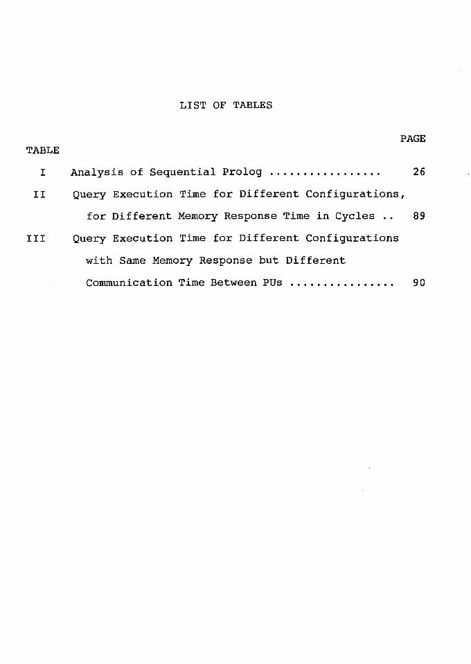
I Analysis of Sequential Prolog. ..... ...... ..... 26
II Query Execution Time for Different Configurations,
for Different Memory Response Time in Cycles .. 89
III Query Execution Time for Different Configurations
with Same Memory Response but Different
Communication Time Between PUs ... ............. 90
LIST OF FIGURES
PAGE FIGURE
1. AND Parallelism vs. OR Parallelism. . . . . . . . . . • . . . 17
2. OR Processes . . . . . . . . . . . . . . . . . . . . . . . . . . . . . . . . . . . . 19
3 . AND Processes . . . . . . . . . . . . . . . . . . . . . . . . . . . . . . . . . . . 21
4.
s.
6.
7.
8.
9.
10.
11.
12.
Graph for Disjoint Subgoals ...••••.......••....•
Graph for Shared Variables .........•••••.•...•..
Graph for Deterministic Function .....••••.....•.
Graph for Map Coloring ••.....•••.........•••.•..
Graph for Detailed Example .......•••...•.....••..
Block Diagram of Architecture •.•......••••••...•
1-iernol:'l' li.i.ercti:-c::ll}' ••••••••••••••••••••••••••••••••
Graph for Number of PEs vs. Cycles •..•••......••.
Graph for Number of PUs vs. Speedup ••••••..••.••
36
38
40
42
49
58
61
92
93
CHAPTER I
INTRODUCTION
The past few years have seen an explosion of interest
in the field of logic programming as reported by Conery [6].
An indication of the interest is attendance at meetings of
researchers in the field. The attendance has gone up from
the 1980 meeting in Hungary to the attendance in the last
meeting. In addition two journals are devoted exclusively to
logic programming, and journals for artificial intelligence,
programming languages, and computer architecture regularly
feature articles related to logic programming.
Much of the current research involves techniques for
implementing logic programming languages, such as Prolog.
One of the attractions of logic programming is the clean
separation of semantics and control. It is easy to separate
specification of what a program should compute from how an
implementation can efficiently compute it as suggested by
Conery [6]. The major advantage of the separation of
semantics from control, however, is the potential for
parallelism. When it is clear what the final result of a
computation has to be, and that any of a number of different
sequences of operations will lead to the result, it is
reasonable to expect to do some of the operations in
parallel. Such is the case with logic programming.
2
The subject of this thesis is the importance of AND
parallelism in the Prolog language. Research presented here
provides a brief inside look at the Prolog language, a
discussion of potential parallelism in Prolog such as
AND/OR, its importance, problems associated with exploiting
the parallelism and some definitive ideas about implementing
an architecture.
Logic programming languages, like languages based on
applicative models, are often inefficient in comparison to
traditional languages when implemented on Von Neumann
architectures. One hope for more efficient implementation
lies in parallel architectures. The philosophy behind the
research presented here is that parallel architectures
should be designed in a "top-down" fashion, proceeding from
the formal model of computation to actual hardware.
The thesis starts with an introduction to logic
programming. The purpose of this chapter is to make the
reader familiar with some of the terms in logic programming.
Some definitions and concepts are presented and the chapter
ends with an example that covers the concepts and the
definitions presented.
The third chapter discusses the historical aspects of some
other concurrent languages. The chapter also presents the
sources of parallelism in Prolog. It provides a reference
point for understanding AND/OR process models. The third
chapter ends by showing the importance of AND parallelism
and some other techniques that can make execution of Prolog
faster.
The fifth chapter discusses some of the attempts made
over the time to exploit the parallelism (specifically AND
parallelism), and the rest of the chapters in the thesis
present the ideas developed for an architecture that is
capable of satisfying all the needs and requirements shown
in earlier chapters for more efficient and faster execution
of AND parallelism.
3
CHAPTER II
INTRODUCTION TO PROLOG
Prolog is a conversational language. Computer
programming in Prolog consists of (1) declaring some facts
about objects and their relationships, (2) defining some
rules about objects and their relationships, and (3) asking
questions about objects and their relationships [25]. The
fundamentals of Prolog are discussed below.
ELEMENTS OF PROLOG
Facts are a key component of Prolog programs. Facts
describe relationships between objects. For example, to
represent that john and mary are related by the fact that
john likes mary, Prolog uses:
likes(john,mary).
In Prolog, a collection of facts is called a database.
In Prolog, a "question" or "query" looks just like a
fact, except a special symbol is put before it. For example,
?- likes(john,mary).
is interpreted as, Does john likes mary ?
5
When a "question" is asked in Prolog, the Prolog
interpreter will search through the database that has been
entered and look for facts that match the fact in the
question. Two facts match if their predicates are the same
(spelled the same way), and if their corresponding arguments
each are the same. If, in response to a question, a match is
found then success is reported; otherwise, failure is
reported.
The objects in a query may be represented by variables.
When Prolog uses a variable, the variable can be either
instantiated or uninstantiated. An instantiated variable is
associated with a specific object, while an uninstantiated
variable is not associated with a specific object. When
Prolog is asked a question containing a variable, the Prolog
interpreter searches through all its facts to find an object
that the variable could stand for. Variables are represented
by words starting with a capital letter.
A "rule" is a general statement about objects and their
relationships. In a rule a variable can stand for different
object in each different use of the rule. In Prolog, a rule
consists of a head and a body. The head and body are
connected by the symbol :- . The " :-" is pronounced "if".
An example is
likes(john,X) :- likes(X,wine).
The above example presents the fact that
john likes anyone who likes wine, or, in other words,
john likes something if it likes wine, or, with variables,
john likes X if X likes wine.
6
A predicate is defined by a mixture of facts and rules.
These facts and rules are called clauses for the predicate.
The word clause is used while referring to either a fact or
a rule. Let us consider the following example.
A person may steal something if the person is a thief
and he likes the thing and the thing is valuable. In Prolog,
this is written as:
may_steal(P,T) :- thief (P) , likes(P,T) , valuable(T) .
Here the predicate being used is may_steal, which has two
variables P and T to represent the idea that some person P
may steal thing T. This rule depends on clauses for thief,
likes and valuable. These could be represented either as
facts or rules, whatever is most appropriate.
Suppose the following database is present:
likes(mary,food).
likes(mary,wine).
likes(john,wine).
likes(john,mary).
To ask if John and Mary like each other, the question
asked is "Does John like Mary and does Mary like John?".
7
The "and" expresses the fact that the motive of question
asked is interested in the conjunction of two goals. This is
represented as,
?- likes(john,mary) , likes(mary,john).
The comma is pronounced "and," and it serves to separate any
number of different goals that have to be satisfied in order
to answer a question. In the above question all the goals
have to be satisfied in order for the sequence to be
satisfied. A fact can cause a goal to be satisfied
immediately, whereas a rule can only reduce the task to that
of satisfying a conjunction of subgoals. If a goal cannot be
satisfied, or if the user asks to search for other possible
solutions, then backtracking will be initiated.
Backtracking consists of reviewing what has been done
and attempting to re-satisfy the goals with an alternative
solution path. When a failure is generated (because all the
alternative clauses for a goal have been tried, or because
another solution is requested by the user), the "flow of
satisfaction" passes back along the way it has come. In
other words, during the solution of a goal, whenever a
8
clause is selected a marker specifying its location is
placed in the database. Then for satisfying subgoals, search
and matching are performed over the existing database. But
when the result of the attempt is a failure, further
attempts start from the point at which the marker was
placed. But to do so it is first necessary to go back to the
point where the marker was placed for the selected clause.
After that Prolog attempts to find an alternative clause for
the appropriate goal. First all the variables that were
instantiated along that path for satisfying the goal are now
made uninstantiated. Then, the interpreter searches on in
the database from where the clause was selected. If it finds
another matching possibility, a marker is placed and the
execution is continued. If no other matching possibility can
be found, the goals fails, and the flow of execution
retreats further until it comes to another place marker
(i.e. backtracking to next high level).
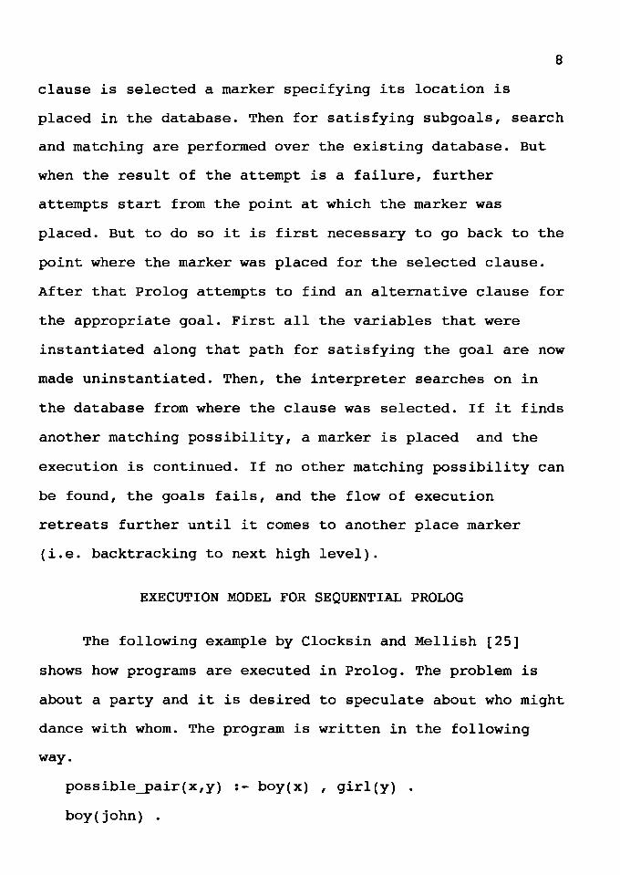
EXECUTION MODEL FOR SEQUENTIAL PROLOG
The following example by Clocksin and Mellish [25]
shows how programs are executed in Prolog. The problem is
about a party and it is desired to speculate about who might
dance with whom. The program is written in the following
way.
possible_pair(x,y) :- boy(x) , girl(y) .
boy(john) .
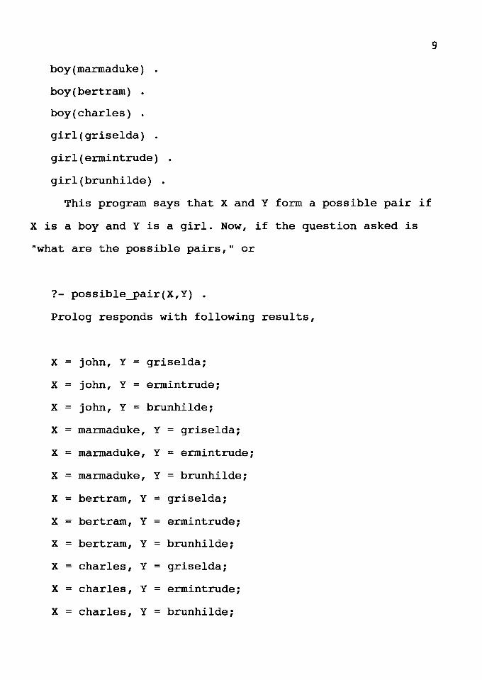
boy(marmaduke) .
boy(bertram) .
boy(charles) .
girl(griselda) .
girl(ermintrude) .
girl(brunhilde) .
This program says that X and Y form a possible pair if
X is a boy and Y is a girl. Now, if the question asked is
"what are the possible pairs," or
?- possible_pair(X,Y) .
Prolog responds with following results,
X = john, Y = griselda;
X = john, Y = ermintrude;
x = john, Y = brunhilde;
X = marmaduke, Y = griselda;
X = marmaduke, Y = ermintrude;
X = marmaduke, Y = brunhilde;
X = bertram, Y = griselda;
X = bertram, Y = ermintrude;
X = bertram, Y = brunhilde;
X = charles, Y = griselda;
X = charles, Y = ermintrude;
X = charles, Y = brunhilde;
9
10
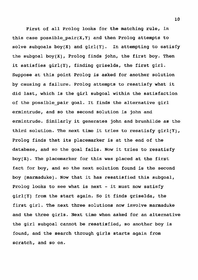
First of all Prolog looks for the matching rule, in
this case possible_pair(X,Y) and then Prolog attempts to
solve subgoals boy(X) and girl(Y). In attempting to satisfy
the subgoal boy(X), Prolog finds john, the first boy. Then
it satisfies girl(Y), finding griselda, the first girl.
Suppose at this point Prolog is asked for another solution
by causing a failure. Prolog attempts to resatisfy what it
did last, which is the girl subgoal within the satisfaction
of the possible_pair goal. It finds the alternative girl
ermintrude, and so the second solution is john and
ermintrude. Similarly it generates john and brunhilde as the
third solution. The next time it tries to resatisfy girl(Y),
Prolog finds that its placemarker is at the end of the
database, and so the goal fails. Now it tries to resatisfy
boy(X). The placemarker for this was placed at the first
fact for boy, and so the next solution found is the second
boy (marmaduke). Now that it has resatisfied this subgoal,
Prolog looks to see what is next - it must now satisfy
girl(Y) from the start again. So it finds griselda, the
first girl. The next three solutions now involve marmaduke
and the three girls. Next time when asked for an alternative
the girl subgoal cannot be resatisfied, so another boy is
found, and the search through girls starts again from
scratch, and so on.
11
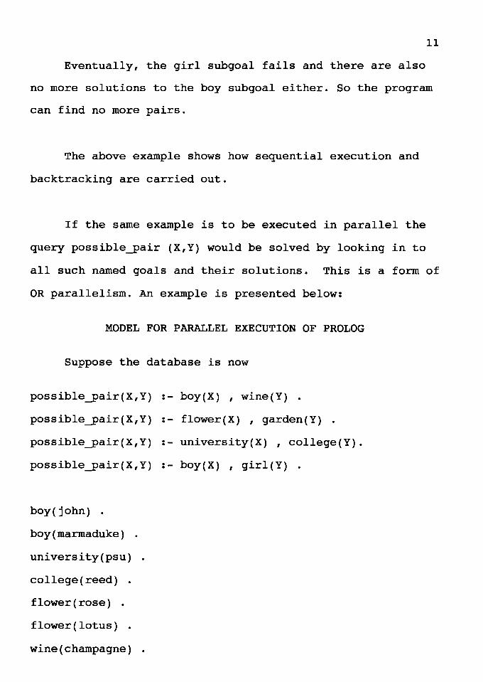
Eventually, the girl subgoal fails and there are also
no more solutions to the boy subgoal either. So the program
can find no more pairs.
The above example shows how sequential execution and
backtracking are carried out.
If the same example is to be executed in parallel the
query possible_pair (X,Y) would be solved by looking in to
all such named goals and their solutions. This is a form of
OR parallelism. An example is presented below:
MODEL FOR PARALLEL EXECUTION OF PROLOG
Suppose the database is now
possible_pair(X,Y) :- boy(X) , wine(Y) .
possible_pair(X,Y) :- flower(X) , garden(Y) .
possible_pair(X,Y) :- university(X) , college(Y).
possible_pair(X,Y) :- boy(X) , girl(Y) .
boy( john) .
boy(marmaduke) .
university(psu) .
college (reed) .
flower(rose) .
flower(lotus) .
wine(champagne) .
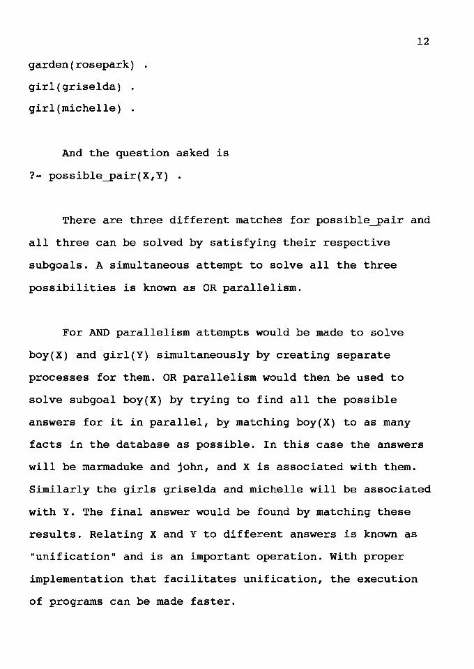
garden(rosepark) .
girl(griselda) .
girl(michelle) .
And the question asked is
?- possible_pair(X,Y) •
12
There are three different matches for possible_pair and
all three can be solved by satisfying their respective
subgoals. A simultaneous attempt to solve all the three
possibilities is known as OR parallelism.
For AND parallelism attempts would be made to solve
boy(X) and girl(Y) simultaneously by creating separate
processes for them. OR parallelism would then be used to
solve subgoal boy(X) by trying to find all the possible
answers for it in parallel, by matching boy(X) to as many
facts in the database as possible. In this case the answers
will be marmaduke and john, and X is associated with them.
Similarly the girls griselda and michelle will be associated
with Y. The final answer would be found by matching these
results. Relating X and Y to different answers is known as
"unification" and is an important operation. With proper
implementation that facilitates unification, the execution
of programs can be made faster.
13
The reader may wish to go in to more detail. This
introduction to Prolog should help in further understanding.
More explanation for the basic concepts of Prolog can be
found in the book by Clocksin and Mellish [25]. The next
chapter gives insight into some other languages, covers
potential sources of parallelism and then deals with AND
parallelism.
CHAPTER III
PARALLELISM IN LOGIC PROGRAMS
The origins of Prolog are shrouded in mystery, as
discussed by Sterling and Shapiro [15]. All that is known is
that the two founders Robert Kowalski and Alain Colmerauer
worked on similar ideas during the early 70's, and even
worked together. The results were the formulation of the
logic programming philosophy and computation model by Robert
Kowalski (1974) and the design and implementation of the
first logic programming language, Prolog, by Alain
Colmerauer and his colleagues (1973).
Variations of Prolog with extra control features, such
as IC-Prolog by Clark and McCabe, 1979 [15] have been
developed, but have proved too costly in random overhead to
be seriously considered as alternatives to Prolog.
Another breed of logic programming languages, which
indirectly emerged from IC-Prolog, is concurrent logic
languages. The first was Relational Language by Clark and
Gregory, 1981 followed by Concurrent Prolog by Shapiro,
1983, Parlog by Clark and Gregory, 1984, GHC by Ueda, 1985,
[15] and a few other proposals. There is another language
"Strand," evolved from Parlog. Strand is available as a
commercial product.
15
The creation of these languages was motivated by
several ideas and requirements. The first was to create a
parallel execution model for logic programs to fully utilize
new parallel computer architectures. The advantage of using
parallel languages exists in a theoretical sense, but
practically it has some very clear disadvantages. In order
for a programmer to avoid various problems and extract
parallelism easily, languages should have clear semantics
and be inherently parallel themselves. Logic programming
languages provide good opportunities for parallelism with
their high level constructs and semantic clarity. But as
mentioned earlier, in order to make use of these
opportunities the user has to be a good programmer, because
logic concurrent languages are difficult to understand and
program.
The other way to exploit the parallelism is to utilize
the AND-OR goal tree in the languages. The AND-OR tree is
inherent in Prolog and so models and methods for efficient
processing of it can help in exploiting the parallelism.
They can be very well supported on some of the existing
architectures.
Execution of a logic program begins when the user
provides an initial goal statement. The execution can be
represented as an AND/OR goal tree, where multiple
descendants of a node indicate a choice of clauses for
resolving the goal at that node.
16
The two major forms of parallelism in logic programs
can be explained in terms of speeding up the search of the
goal tree as proposed by Conery [6]. OR parallelism refers
to a parallel search strategy - when a search process
reaches a branch in the tree, it can start parallel
processes to search each descendant branch. AND parallelism
corresponds to parallel construction of a branch - when the
interpreter knows a number of steps must be done to complete
a branch, it can start parallel processes to perform those
steps. The name for OR parallelism comes from the fact that
in nondeterministic programs, we are often satisfied with
any correct answer. When any of the processes started at a
choice point (a choice point is a point at which a
particular clause is selected initially for solution of the
goal) finds a result, the original goal is solved. The name
for AND parallelism is based on the fact that all steps must
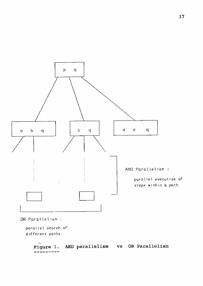
succeed in order for a result to be produced. The following
example (Figure 1) by Conery [6] clarifies OR parallelism
and AND parallelism.
p q
a b q
D
DR Pora l le l 1sri :
parallel search of
different paths
c q
D
Figure 1. AND parallelism
d
17
e q
AND Parol tel ISM :
parallel execution of
steps within a path
vs OR Parallelism
Goal: p A q.
p - a A b.
p - c.
p - d A e.
Explained in terms of the structure of a program, OR
parallelism is the parallelism obtained from parallel
execution of different clauses for the goal clause. AND
parallelism is the parallelism obtained from parallel
execution of the goals in the body of a clause.
A third source of parallelism is parallelism in low
level operations, such as unification. Systems exploiting
parallelism at this level are typically but not limited to
sequential interpreters.
MODELS FOR OR PARALLELISM
18
Abstract models for OR parallelism fall into three
broad categories per Conery [5]. The first, called 11 pure 11
OR parallelism, consists of a parallel search of the goal
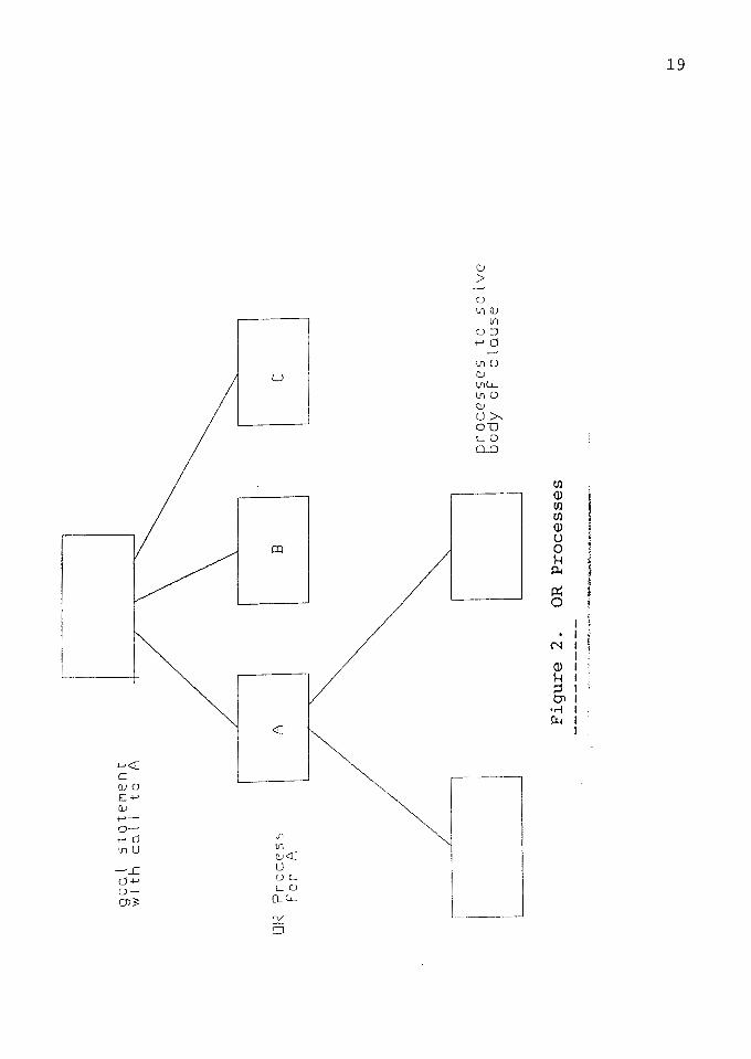
tree. The second form of parallelism is based on objects
called OR processes. Each process is responsible for
executing a small piece of the program (Figure 2). The third
form, called search parallelism is based on a physical
partitioning of the program. Clauses are stored in different
nodes of a machine such as a multiprocessor database
machine.
go
al
sto
ter1
en
t w
I th
ca
l l
to
A
OR
Pro
cess
f'
or
A
A
B
Fig
ure
2.
OR
P
ro
cess
es
...;
..,.
o,,.
_,.,
,.,,
~~c
""""'"""'"'4'<~~....,-r,.'~'"°""'"''~·""'<1<7"--~-~
c
pro
cess
es
to
solv
e
bo
dy
oF
cla
use
.....
l.O
20
OR processes try to create as many results as possible,
but the results are passed back to the parent one at a time,
as the parent demands them. The models for AND parallelism
and AND processes are described by Conery [5] as follows.
MODELS FOR AND PARALLELISM
AND parallelism is the parallel solution of more than
one goal in a given goal statement. The central problem in
implementing this form of parallelism is management of
variables occurring in more than one literal of the goal
statement. In a goal statement such as
p(X) "' q(X) •
the variable X occurs in both goals. To solve the goal
statement we need to find a value for X that satisfies both
p and q. Most abstract models for AND parallelism handle
this problem the same way: they allow only one of the goals
to bind the shared variable, and postpone solution of the
others until the variable has been bound.
Stream parallelism interprets a clause such as,
p q "' r.
to mean " process p can be replaced by the system of
processes q and r" as shown by Conery [6]. In this
interpretation, literals in a goal statement are processes,
and variables occurring in more than one literal are
communication channels between the literals.
I l'1j I I-'· I \Cl I r::: I Ii I (l) I I VJ I .
l i g;; ' 0
t'd Ii 0 (') (l) tll tll (l) tll
1Z
-lflu :J 0 .., ~o
CD<n 0 IU (\)
0 lfl ~~lfl
-f'D lf\ .+ ln c-t (()
0 J rl
rt 0 0 r1) ,-
3 lfl r1)
/
:YD (() :;:o p Q_--0
J 00 -rin
l1J () lfl ~lfl
Pl1J Clfl lfl (() -ri
0
'
22
AND Processes
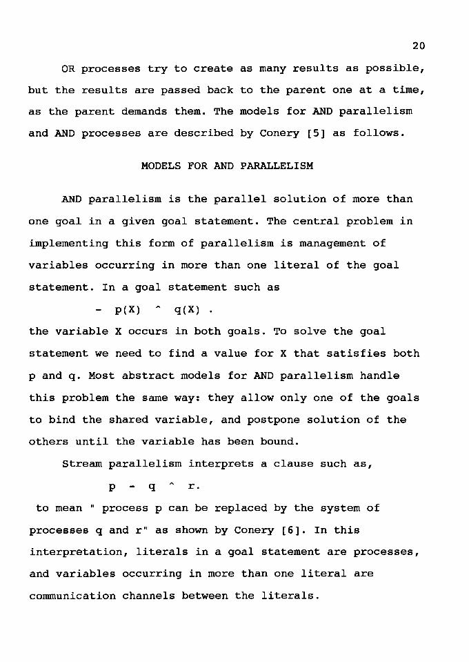
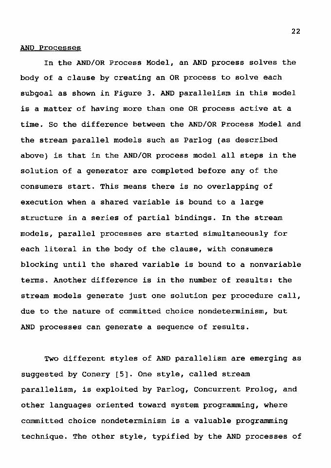
In the AND/OR Process Model, an AND process solves the
body of a clause by creating an OR process to solve each
subgoal as shown in Figure 3. AND parallelism in this model
is a matter of having more than one OR process active at a
time. So the difference between the AND/OR Process Model and
the stream parallel models such as Parlog (as described
above) is that in the AND/OR process model all steps in the
solution of a generator are completed before any of the
consumers start. This means there is no overlapping of
execution when a shared variable is bound to a large
structure in a series of partial bindings. In the stream
models, parallel processes are started simultaneously for
each literal in the body of the clause, with consumers
blocking until the shared variable is bound to a nonvariable
terms. Another difference is in the number of results: the
stream models generate just one solution per procedure call,
due to the nature of committed choice nondeterminism, but
AND processes can generate a sequence of results.
Two different styles of AND parallelism are emerging as
suggested by Conery [5]. One style, called stream
parallelism, is exploited by Parlog, Concurrent Prolog, and
other languages oriented toward system programming, where
committed choice nondeterminism is a valuable programming
technique. The other style, typified by the AND processes of
the AND/OR Process Model, is oriented toward a more
exploratory style of nondeterminism.
23
The research in this thesis seeks to exploit the AND/OR
Process Model form of AND Parallelism.
A later part of this thesis presents a different way to
perform unification which helps to improve the overall speed
of execution.
The attempts to exploit parallelism in the AND/OR
Process Model always cover both AND and OR parallelism.
There are many papers that present work on OR parallelism,
[2,11,14,16,20] the reason being OR parallelism is very
natural to detect and relatively easy to implement. On the
other side the research on exploiting AND parallelism is
more limited. This may be because of the fact that to
exploit AND Parallelism the issue of shared variables needs
special attention. Each literal in the clause generates OR
process and many results are produced. To find one unique
solution and also to store the bindings and to maintain the
bindings requires special attention.
The goal in this thesis is to stress the importance of
AND parallelism and speed of unification on the overall
execution speed, and so arguments and results are now
24
presented to show that AND parallelism is important.
The execution speed of sequential logic programming
systems has been constantly improving since Warren's Prolog
interpreter/compiler for the DECsystem-10 proved the
usefulness of a logic as a practical programming tool as
shown by Kowalski [12].
Of the different sources of parallelism present in
logic programs, the study of AND parallelism is important,
because among other reasons it offers promising results even
for highly deterministic programs as proved by Hermengildo
[17].
ANALYSIS OF SEQUENTIAL PROLOG PROGRAMS
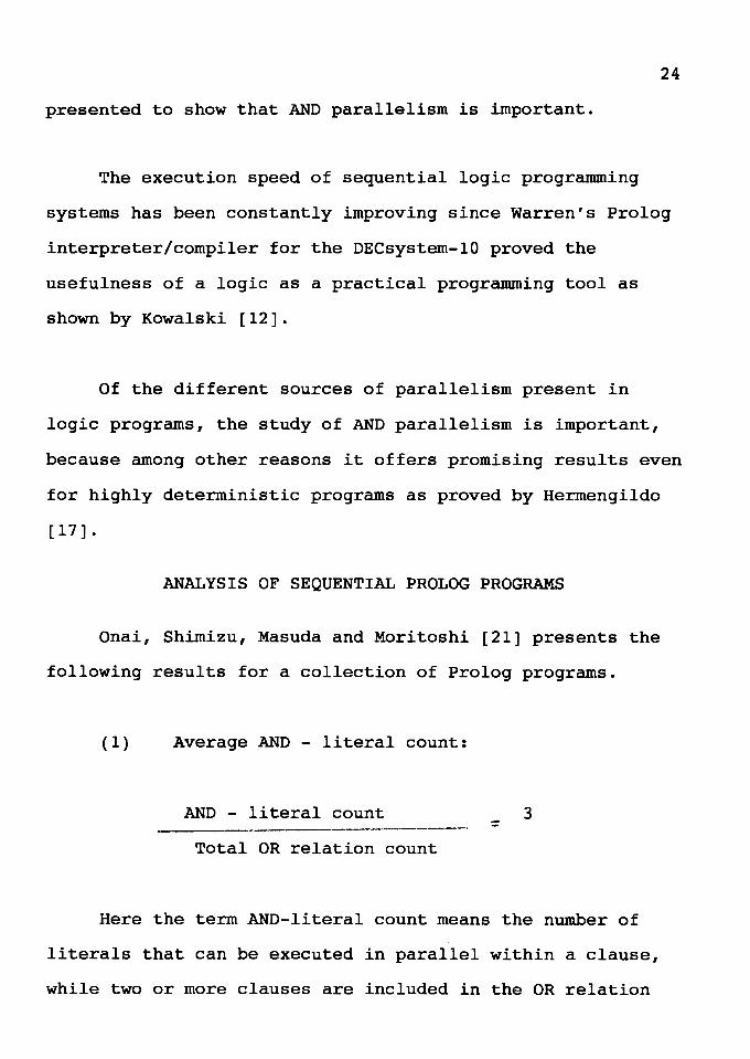
Onai, Shimizu, Masuda and Moritoshi [21] presents the
following results for a collection of Prolog programs.
(1) Average AND - literal count:
AND - literal count 3 ::
Total OR relation count
Here the term AND-literal count means the number of
literals that can be executed in parallel within a clause,
while two or more clauses are included in the OR relation
25
count when they have same head predicate symbol and the same
number of arguments.
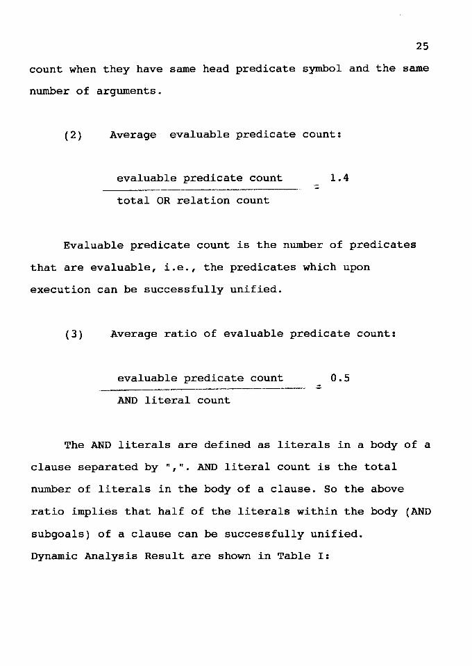
(2) Average evaluable predicate count:
evaluable predicate count
total OR relation count :::
1.4
Evaluable predicate count is the number of predicates
that are evaluable, i.e., the predicates which upon
execution can be successfully unified.
(3) Average ratio of evaluable predicate count:
evaluable predicate count 0.5
AND literal count
The AND literals are defined as literals in a body of a
clause separated by ",". AND literal count is the total
number of literals in the body of a clause. So the above
ratio implies that half of the literals within the body (AND
subgoals) of a clause can be successfully unified.
Dynamic Analysis Result are shown in Table I:
26
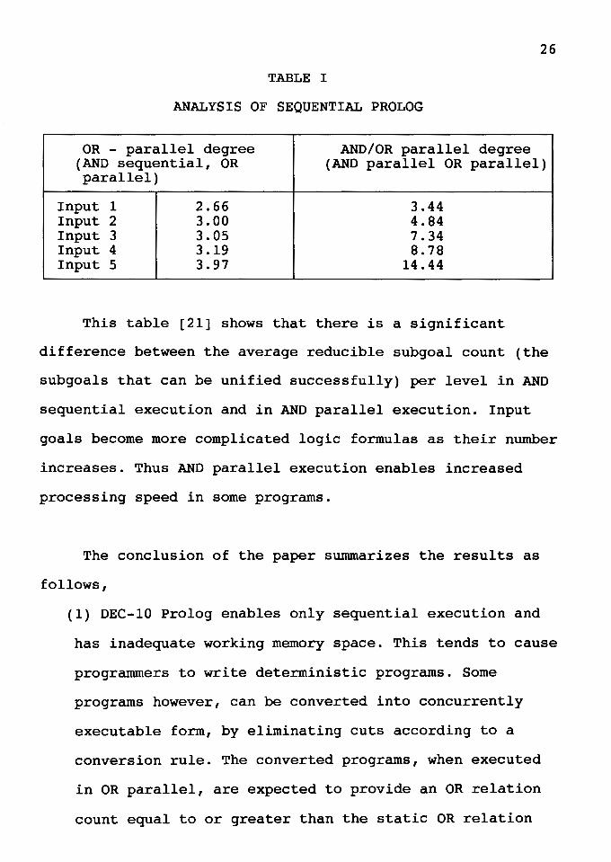
TABLE I
ANALYSIS OF SEQUENTIAL PROLOG
OR - parallel degree AND/OR parallel degree (AND sequential, OR (AND parallel OR parallel) parallel)
Input 1 2.66 3.44 Input 2 3.00 4.84 Input 3 3.05 7.34 Input 4 3.19 8.78 Input 5 3.97 14.44
This table [21] shows that there is a significant
difference between the average reducible subgoal count (the
subgoals that can be unified successfully) per level in AND
sequential execution and in AND parallel execution. Input
goals become more complicated logic formulas as their number
increases. Thus AND parallel execution enables increased
processing speed in some programs.
The conclusion of the paper summarizes the results as
follows,
(1) DEC-10 Prolog enables only sequential execution and
has inadequate working memory space. This tends to cause
programmers to write deterministic programs. Some
programs however, can be converted into concurrently
executable form, by eliminating cuts according to a
conversion rule. The converted programs, when executed
in OR parallel, are expected to provide an OR relation
count equal to or greater than the static OR relation
27
count. Also, AND parallel execution may provide a higher
parallel degree.
(2) About half or more of executed subgoals are
evaluable predicates. The execution speed of evaluable
predicates affect that of the program.
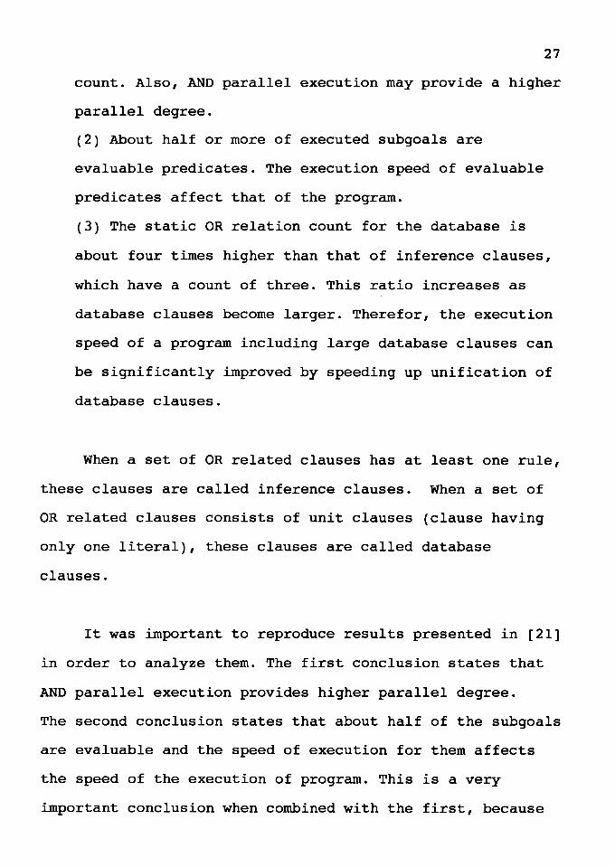
(3) The static OR relation count for the database is
about four times higher than that of inference clauses,
which have a count of three. This ratio increases as
database clauses become larger. Therefor, the execution
speed of a program including large database clauses can
be significantly improved by speeding up unification of
database clauses.
When a set of OR related clauses has at least one rule,
these clauses are called inference clauses. When a set of
OR related clauses consists of unit clauses (clause having
only one literal), these clauses are called database
clauses.
It was important to reproduce results presented in [21]
in order to analyze them. The first conclusion states that
AND parallel execution provides higher parallel degree.
The second conclusion states that about half of the subgoals
are evaluable and the speed of execution for them affects
the speed of the execution of program. This is a very
important conclusion when combined with the first, because
28
AND parallelism gives higher degree of parallelism and if
the subgoals in clauses are executed faster (AND
parallelism) the overall execution speed of the program also
improves. So it is very clear that exploitation of AND
parallelism is important and also the better the execution
method the better the improvement in the program execution
speed.
The third conclusion states the fact that there are
more database clauses than inference clauses and so if
unification speed is improved the execution speed of
programs can be significantly improved.
So from this research it is made very clear that AND
parallelism is very important and unification speed is also
very important. Taking these results as a basis to design a
system that will provide higher speed for the execution of
Prolog programs, the rest of the thesis presents a design
that incorporates and supports efficient execution of AND
parallelism and faster unification.
The analysis presented in [21] analyzed about 39
programs. So the analysis covers a wide spectrum of logic
programs, and the results obtained are important.

29
Based on these conclusions, now the attempt is made to
describe the architectural design that will support AND
parallel execution and also the method for unification.
Attempts made for the same cause by some other researchers
are also discussed in the beginning of the next chapter.
CHAPTER IV
AND PARALLELISM
In Prolog the basic way of execution is as follows :
(1) A database is prepared and stored based on available
information.
(2) Prolog is asked to search and find an answer for a
particular question.
(3) Prolog looks in its database and replies "yes" or "no"
to report success or failure.
(4) In most cases the problem is solved here but if the user
is not satisfied with a particular answer it is possible to
ask Prolog for alternative solutions for that question.
Prolog would again look into its database and would report
any other solutions if alternatives exists, else it would
report failure.
As discussed earlier the database of Prolog consists of
facts or rules, and they are known as clauses. We have also
discussed how facts and rules are different from each other
and their format.
31
When Prolog starts the process of solving a question it
would look into the database starting from the top of
database for a matching fact or rule. Prolog would look for
only those rules that have rule head matching the head of
the rule in the question and also having the same number of
arguments.
If the question is of the form fact and if the
matchings are all facts then Prolog would go through all
matching facts one after another and would report an answer
every time. If the answer found at the very first matching
fact is the answer that is sufficient and if no other answer
is requested then Prolog would stop there. If that answer is
not a success or some other alternatives of that answer are
wanted then Prolog would continue, until it runs out of all
matching facts.
If the question asked is of the form rule and the
matchings are all rules with subgoals in their body (not a
unit clause which has only one literal) then the execution
now is not simply reporting "yes" or "no" as soon as a match
is found. After finding the matching rule Prolog will have
to seek a solution of that rule, because rules have some
subgoals and those subgoals need to be solved to determine
the success or failure. In parallel processing all the
possible matching rules are found and a concurrent search is
32
conducted for many or all of them depending upon the
available capacity. The procedure of seeking the solution of
all matching rules in parallel is known as spawning an OR
process for each match. Solutions from all of these OR
processes would be obtained after they attempt to solve
their rule.
Rules are of the form
head ( ) :- subgoal 1( ), subgoal 2( ), •..•
After matching the head, the subgoals should be solved. AND
processes are created that would seek a solution for each
subgoal. There are different ways in which the solution of a
subgoal can be obtained. Some of the methods are not
efficient, like starting the execution by solving subgoal 1
first, then subgoal 2, etc. A detailed discussion of a
methodology for efficient execution of AND processes known
as ordering of subgoals (literals) described by Conery [6]
follows.
The basis for the ordering of literals in the body of a
clause is the sharing of variables. One way to solve the
dependence problem whenever two or more literals have a
variable in common is to designate one of the literals as
the generator for the variable. It should be solved before
the other literals. The solution of the generator literal is
intended to create a value for the corresponding variable.
33
After the generator is solved, the other literals containing
the variable, consumers, may be scheduled for solution. A
generator should be defined for every variable in a rule. It
is possible that the solution of a generator will not bind
the variable, and consumers will still have a variable in
common. In that case one of the consumers is then made
generator of that variable.
Here the difference between the AND/OR process model
and concurrent languages becomes evident. It appears that
concurrent systems do not require literals to be ordered,
since processes are started for all literals simultaneously
when the clause is invoked. However, some of those processes
immediately block, waiting for input via the solution of
other literals. In the AND/OR process model, we delay
creation of processes for the literals that would be blocked
immediately. So the difference is that in one system a
process is created and then blocked until a shared variable
is bound, while in the other type the process is not created
until the processes it depends on have completed.
ORDERING OF LITERALS
Some rules for ordering literals that have been
presented by Conery [6] are as follows. The first rule is
that the head of a clause is the generator for all variables
instantiated when the clause is invoked.
34
There are two other rules that can be used to complete
the process and make sure every variable has a generator.
Use of different rules alone or in different combinations
leads to different orderings, enabling more or less
parallelism in the solution, but in all cases the AND
process will not fail due to incorrect ordering.
The second rule, the connection rule, calls for
selection of the literal with the largest number of
instantiated variables. The third rule is the left most
rule, which simply says the first (left most) literal
containing a variable should be generator of that variable.
This is a reasonable assumption, since, in Prolog programs,
solution of a goal containing unbound variables often binds
the variables. When the left most rule selects the left most
occurrence of a variable it is selecting a literal that
would see the variable as unbound if the clause was solved
with the ordering generated so far. This rule is also a
useful safety feature, since, by itself, it guarantees every
variable will have a generator.
There is a rule for ordering literals based on I/O
modes known as the I/O mode rule. In this rule some of the
literals in the body may have I/O modes, and this mode has
to be declared by the user at the beginning. For example
mode (is, [?, +]) •
35
This declaration shows that the goal with predicate
"is" has two arguments. A plus means the corresponding term
must be a ground term when a goal is solved. In other words,
"is" can never be a generator for a variable occurring in a
term in this argument position. A minus sign (not shown
here) means the corresponding argument must be an
uninstantiated variable that will be bound during solution
of this literal. A question mark in the mode declaration
means the mode is neither plus nor minus, i.e., the literal
can be either a producer or a consumer.
Given the above mode declaration and the goal
A is B + C
a system may designate this call to "is" as the generator of
A (but it is allowed to choose another goal containing A),
but this call cannot be generator for either B or C.
Since mode declarations are known before a clause is
called, the I/O mode rule has to be applied at "compile
time", when the clause is first loaded into the system. The
other rules can be applied at runtime, when the AND process
is created, since they depend on the pattern of variable
instantiation in the clause and this is established by the
unification done by the parent OR process.
An example in [6] about how the rules work is presented
here.
~ /
I x I t-:rj I ..... (D I
"° I (:j I ti I CD I I
*'" I . GJ ti Pl
tO !:1"
t-n ---.., ---.., 0 ti
0 ..... Ul w. 0 I-'· ::i rt
(/)
=::;--- (:j t1
"° 0 Pl I-' Ul
9£
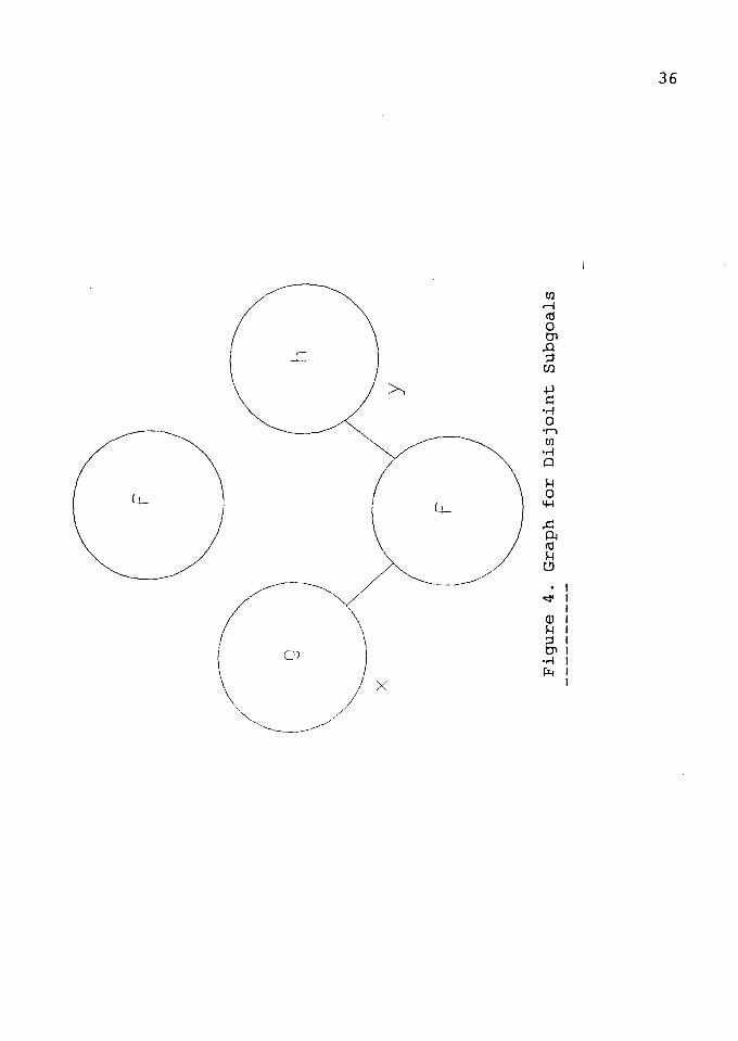
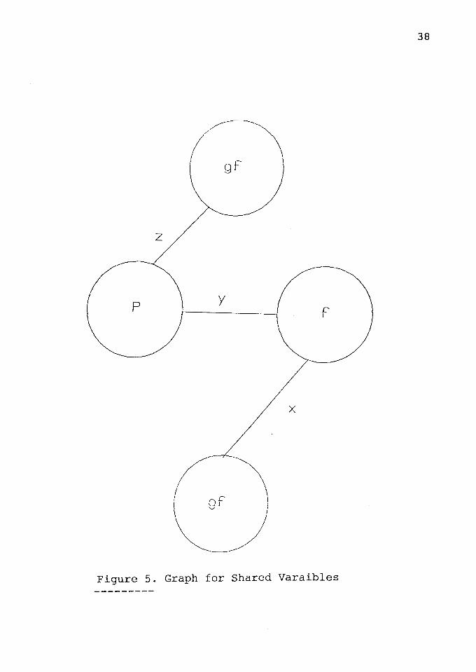
EXAMPLE:
37
The ordering algorithm can be illustrated by
four examples, each showing a different pattern of variable
instantiation in the body of a clause.
Call:
f (A,B).
Clause:
f(X,Y) g(X) h(Y).
* Disjoint Subgoals (Figure 4):
f(X,Y) - g(X) ~ h(Y).
If neither X nor Y is bound when the clause is called,
or if they are bound to terms not containing a variable in
common, the literals are independent. Neither is a
predecessor of the other when both X and Y are
uninstantiated when the process is created. The left most
rule can be used to designate g(X) as the generator of X and
h(Y) as the generator of Y. If there are n solutions for
g(X) and m ways to solve h(Y), then the domain of results
for f [D(f)] would contain n * m pairs of X and Y values.
The remaining pairs, after the first, will be created in
response to redo messages.
,
x
j
BE
16 .J
j6
d
z
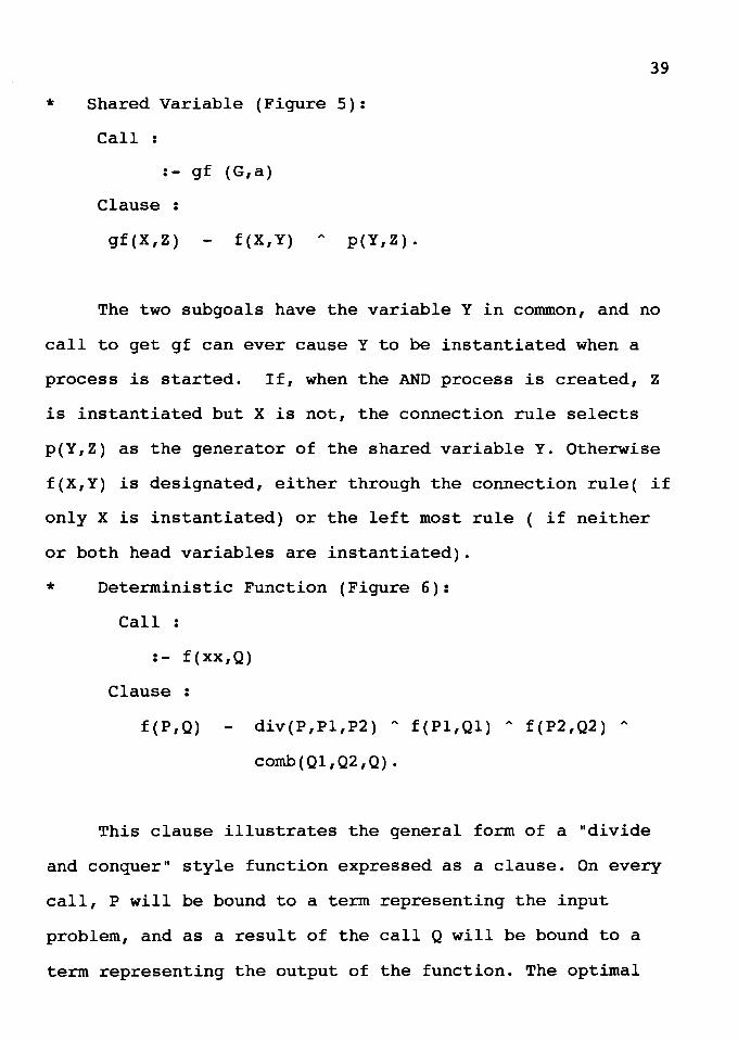
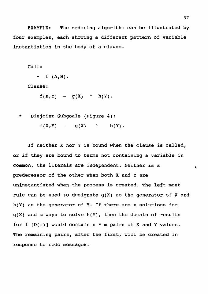
* Shared Variable (Figure 5):
Call :
:- gf (G,a)
Clause :
gf (X,Z) f(X,Y) ,..
p(Y,Z).
39
The two subgoals have the variable Y in common, and no
call to get gf can ever cause Y to be instantiated when a
process is started. If, when the AND process is created, Z
is instantiated but X is not, the connection rule selects
p(Y,Z) as the generator of the shared variable Y. Otherwise
f(X,Y) is designated, either through the connection rule( if
only X is instantiated) or the left most rule ( if neither
or both head variables are instantiated).
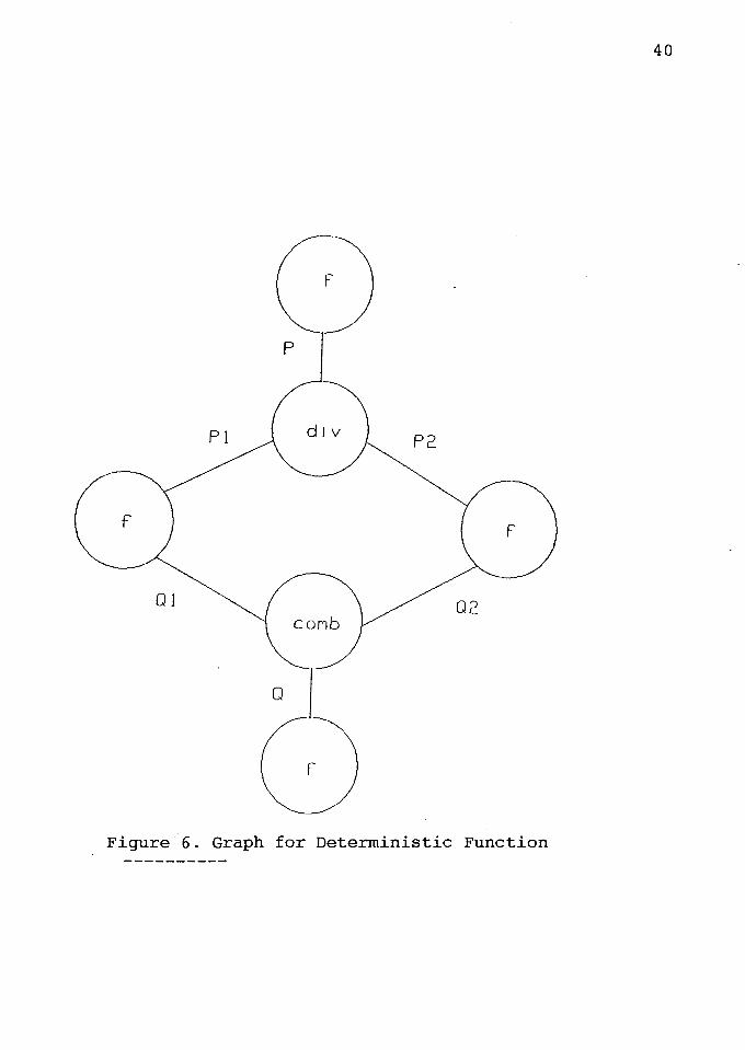
* Deterministic Function (Figure 6):
Call :
:- f (xx,Q)
Clause
f (P,Q) div(P,Pl,P2) " f(Pl,Ql) " f(P2,Q2) "
comb(Ql,Q2,Q).
This clause illustrates the general form of a "divide
and conquer" style function expressed as a clause. On every
call, P will be bound to a term representing the input
problem, and as a result of the call Q will be bound to a
term representing the output of the function. The optimal
0
20 IO
2d
d
Ov
41
ordering of subgoals is : divide problem P into independent
subproblems Pl and P2; then solve Pl and P2 in parallel via
the recursive calls, instantiating Ql and Q2; when both are
done the answer can be constructed from Ql and Q2.
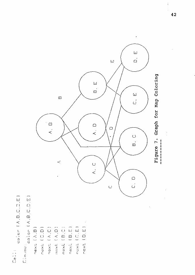
Map coloring
color(A,B,C,D,E)
next(A,B) A next(C,D) A next(A,C) A next(A,D) A
next(B,C) A next(B,E) A next(C,E) A next(D,E).
The goal of this procedure is to see if there is an
assignment of one of four colors to each region of the map,
such that no two adjacent regions have the same color. The
procedure for next is simply twelve ground assertions, one
for each legal pair of adjacent colors. For example,
next(red,blue) is asserted, but next(green,green) is not,
because two adjacent regions should not have the same color.
Also for each clause next (Cl,C2) we need the corresponding
clause next (C2,Cl). If it is assumed that every map be
colored by four colors, then the procedure for next has
twelve clauses.
Graph for Map coloring
When this procedure is called with none of the
variables in the head instantiated, the graph shown in
Figure 7 is created. The literal ordering shown in the
figure is produce by first using the left most rule to
designate next(A,B) as the generator for both A and B. After
Ca
1 l
: co
lor
( A
.B.C
.D.E
l
Clo
use: co
lor
(A.8
.C.D
.El
nex
l [/
\. 8
)
nex
l (
C.D
l
nex
t..
(A.C
l
ne
xt.
(A
. 0
l
n~xl
:.
(8.C
l
' (
B .E
l n
ex
t.-
ncx
l (
C .E
l
nex
l ( 0
. E
l
~ A
. B
A
~
/ 8
c
C.
E
Fig
ure
7.
Gra
ph
fo
r
Map
C
olo
rin
g
E
~
to.)
43
that the connection rule was used to identify the three
literals in the middle row of the graph as the generators of
the other three variables, leaving the remaining four
literals as consumers. All nodes in the graph are calls to
next; the labels show the arguments of the call. The first
values from the generators in the middle row form an
unacceptable combination of values for some of the consumers
on the bottom row. The third and fourth literals working
independently and in parallel, assign the same color to
regions C and D, so one of the assignments will have to
change. The nodes in the top two rows are all immediate
predecessors of head clause.
EXECUTION ALGORITHM
Once the matchings of a clause have been found and a
clause (or clauses) is (are) selected, ordering of literals
is done using some combination of the rules. Then those
literals have to be executed. A methodology proposed by
Conery [6] is discussed here.
When execution begins then, depending on the ordering
of literals, some literals which are independent or
generators of variables are chosen for solution and OR
processes are created for those literals. When success is
obtained for some processes, OR processes can be started for
some other literals. When any descendant OR process fails
44
then backtracking is performed.
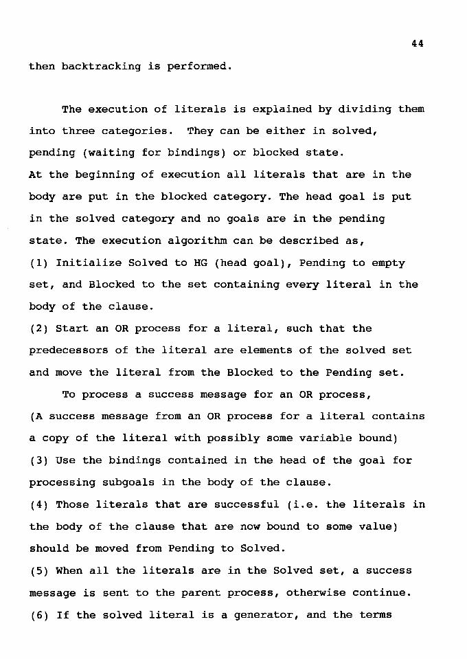
The execution of literals is explained by dividing them
into three categories. They can be either in solved,
pending (waiting for bindings) or blocked state.
At the beginning of execution all literals that are in the
body are put in the blocked category. The head goal is put
in the solved category and no goals are in the pending
state. The execution algorithm can be described as,
(1) Initialize Solved to HG (head goal), Pending to empty
set, and Blocked to the set containing every literal in the
body of the clause.
(2) Start an OR process for a literal, such that the
predecessors of the literal are elements of the solved set
and move the literal from the Blocked to the Pending set.
To process a success message for an OR process,
(A success message from an OR process for a literal contains
a copy of the literal with possibly some variable bound)
(3) Use the bindings contained in the head of the goal for
processing subgoals in the body of the clause.
(4) Those literals that are successful (i.e. the literals in
the body of the clause that are now bound to some value)
should be moved from Pending to Solved.
(5) When all the literals are in the Solved set, a success
message is sent to the parent process, otherwise continue.
(6) If the solved literal is a generator, and the terms
bound by the generator contain unbound variables, then
generators should be designated for those variables.
The next problem is to see what happens to the
solution of an AND process when one of its OR subprocesses
fails. Naturally there should be some way in which the
execution can be carried out. In sequential Prolog,
sequential backtracking is performed, but this is not
efficient for parallel processes. It would be advantageous
if there is some other way then sequential backtracking,
because sequential backtracking slows down the parallel
process. So a methodology to do backtracking for parallel
processes proposed by Conery [6] is now discussed.
45
There are two simple suggestions for making
backtracking faster for parallel processes. One is to follow
the syntactic order of literals in the body of the clause.
The other way is to backtrack per the data flow graph of
clause. But it is shown that backtracking per the syntactic
order of literals in a clause body results in many
unnecessary steps that can be avoided [6].
The other way is to have backtracking based on the data
flow graph, which gives results close to that of intelligent
backtracking and is comparatively easy to understand as
shown by Conery [6] and discussed below.
46
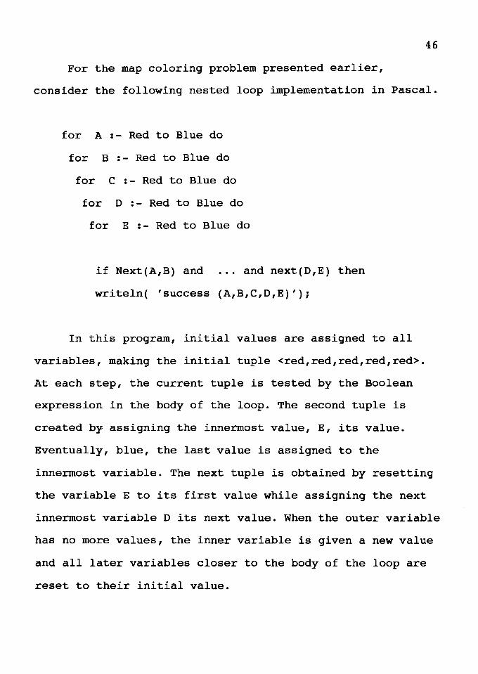
For the map coloring problem presented earlier,
consider the following nested loop implementation in Pascal.
for A :- Red to Blue do
for B :- Red to Blue do
for C :- Red to Blue do
for D :- Red to Blue do
for E :- Red to Blue do
if Next(A,B) and ... and next(D,E) then
writeln( 'success (A,B,C,D,E)');
In this program, initial values are assigned to all
variables, making the initial tuple <red,red,red,red,red>.
At each step, the current tuple is tested by the Boolean
expression in the body of the loop. The second tuple is
created by assigning the innermost value, E, its value.
Eventually, blue, the last value is assigned to the
innermost variable. The next tuple is obtained by resetting
the variable E to its first value while assigning the next
innermost variable D its next value. When the outer variable
has no more values, the inner variable is given a new value
and all later variables closer to the body of the loop are
reset to their initial value.
47
In this method 625 5-tuples of colors are generated,
where the first 81 have the form <red,red,C,D,E>. A and B
cannot have the same color - there is a literal next(A,B) in
the test - but the Pascal program blindly generates 81
unusable tuples. In a logic program the term
next(A,B) is the generator of A and B, and it never
instantiates both A and B to the same color, thus
effectively preventing the construction of a large number of
useless tuples. Now the backward execution algorithm is
presented which is more efficient than the type discussed
above.
Backward Execution Algorithm
When a fail message is received for a literal, the OR
process for one of the generators must bind its variables to
different values. The backward execution algorithm can be
divided into three sections. The first part identifies which
generator should bind its variable to a new value. The
second part updates the variables generated by the
generator. The third part resets other generators.
Selection of the generator is based on marks on all
literals in the candidate set. A mark on a generator means
that the generator may be directly or indirectly responsible
for the failure. So markers that are put on the generators
help in determining which generator should be selected. The
selected generator is the latest in the linear ordering
48
marked with L, where L is a literal.
Next, the AND process must decide which generators must
be reset after the selection of L as the backtrack literal
(now identified as BL). This potentially means every
generator following BL in the linear ordering. Only those
generators that contribute information to the solution of
any successors of BL and BL need to be reset. In other
words, the literals with BL in their candidate set must be
reset.
Now a detailed example is discussed by John Conery [6]
is presented below:-
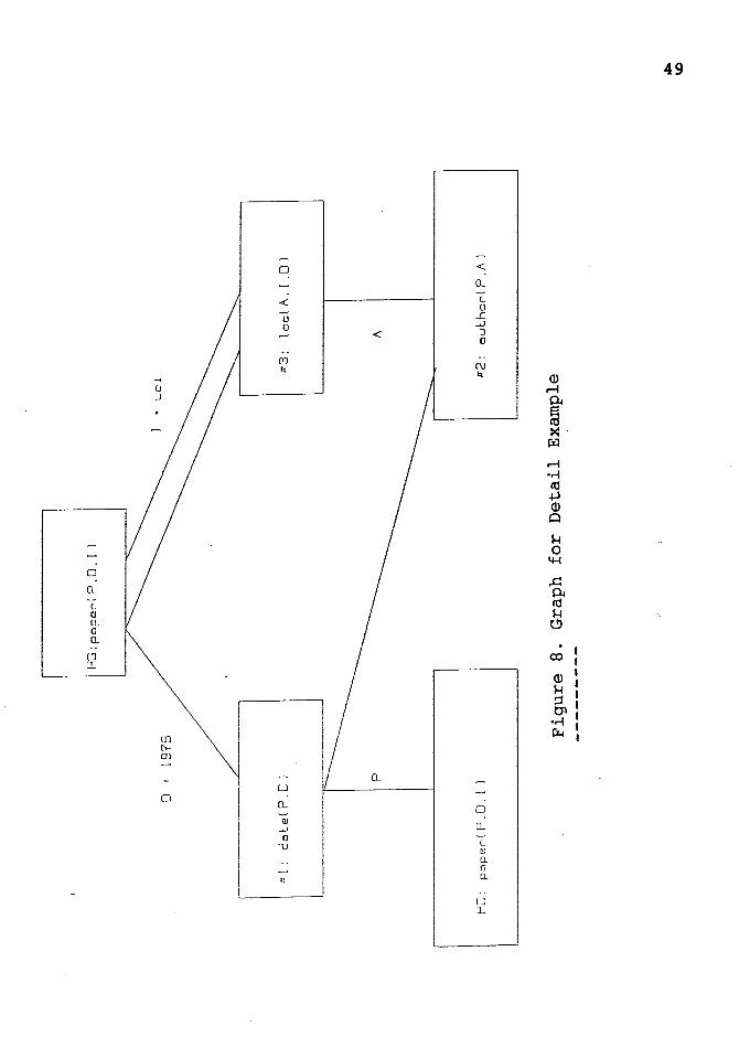
This example (Figure 8) tries to solve a question about
paper, paper(P, 1978, uci), meaning that a paper P, written
by a author A in (1978) at uci.
The applicable rule is
paper(P,D,I) :- date(P,D) "'
"'
author(P,A)
loc(A,I,D).
After matching, the rule becomes
paper(P, 1978, uci) - date(P, 1978) "' author(P,A)
"'loc(A, uci, 1978).
I t'rj I I I-'· I l.O I ~ I ti I CD I I
CX>
G) ti P>
"O ::t 1-h 0 ti
0 CD rt
l I P> I-'·
j I-' I ! tr:!
x
~ I-' CD
I n
u 0 u ('J
J
u 0
" I\)
0 [ ('"""
J 0 J
lJ
>
>
:,
(L
0 r-ro
u 0
" w
0 0
>
0
0
lD -<J m
lJ
0
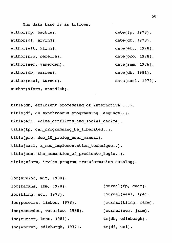
The data base is as follows,
author(fp, backus).
author(df, arvind).
author(eft, kling).
author(pro, pereira).
author(sem, vanemden).
author(db, warren).
author(sasl, turner).
author(xform, standish).
50
date ( fp, 1978).
date(df, 1978).
date(eft, 1978).
date(pro, 1978).
date(sem, 1976).
date(db, 1981).
date(sasl, 1979).
title(db, efficient_processing_of_interactive ... ).
title(df, an_synchronous_programming_language .. ).
title(eft, value_conflicts_and_social_choice).
title(fp, can_programming_be_liberated .. ).
title(pro, dec_lO_prolog_user_manual).
title(sasl, a_new_implementation_technique .. ).
title(sem, the_semantics_of_predicate_logic .. ).
title(xform, irvine_program_transformation_catalog).
loc(arvind, mit, 1980).
loc(backus, ibm, 1978).
loc(kling, uci, 1978).
loc(pereira, lisbon, 1978).
loc(vanemden, waterloo, 1980).
loc(turner, kent, 1981).
loc(warren, edinburgh, 1977).
journal(fp, cacm).
journal(sasl, spe).
journal(kling, cacm).
journal(sem, jacm).
tr(db, edinburgh).
tr(df, uci).
loc(warren, sri, 1982).
There are no mode declarations, so no literals are
designated as generators or non-generators in the static
analysis.
When the process is created, variables D and I are
bound to 1978 and uci respectively. The head goal, HG, is
designated as the generator of these variables, the set of
bound variables, G, is {D,I}, and the set of unbound
variables, U, is {P,A}. This is from the ordering rules
presented earlier.
51
The connection rule is applied to connect a set of
literals to the head, by looking for literals containing
variables in both G and U. The first pass through the list
of literals finds two that meet this criterion. date(P,D)
contains P, a variable with no generator yet and D, a
variable generated by the head, so it is designated as the
generator of P. Similarly, loc(A,I,D) becomes the generator
of A. U is now empty, and all literals have been ordered.
The order is literal date() is #1, author() is #2 and
loc() is #3.
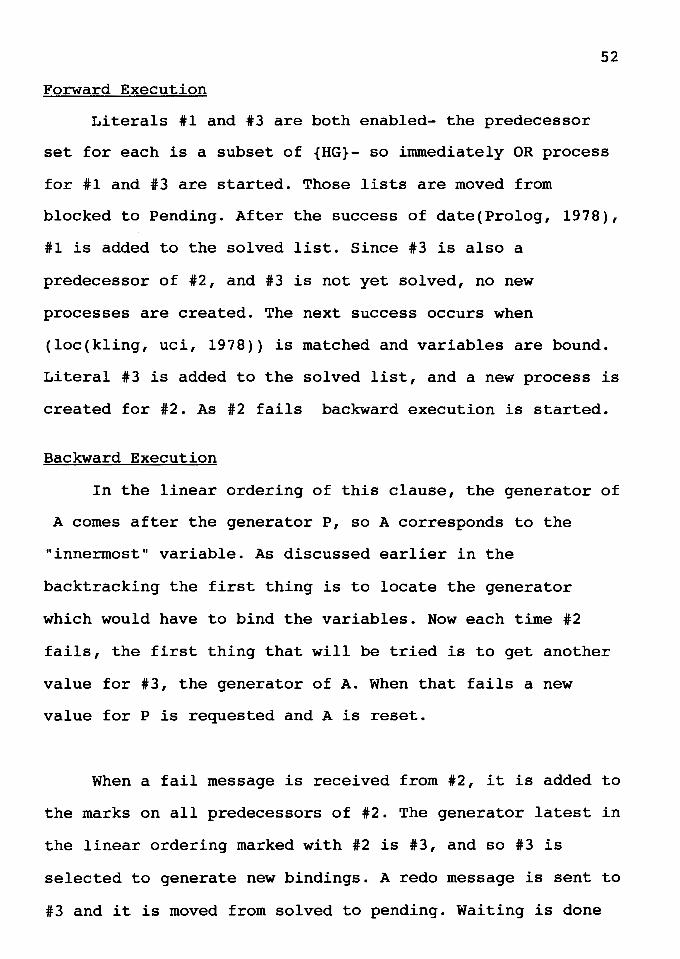
52
Forward Execution
Literals #1 and #3 are both enabled- the predecessor
set for each is a subset of {HG}- so immediately OR process
for #1 and #3 are started. Those lists are moved from
blocked to Pending. After the success of date(Prolog, 1978),
#1 is added to the solved list. Since #3 is also a
predecessor of #2, and #3 is not yet solved, no new
processes are created. The next success occurs when
(loc(kling, uci, 1978)) is matched and variables are bound.
Literal #3 is added to the solved list, and a new process is
created for #2. As #2 fails backward execution is started.
Backward Execution
In the linear ordering of this clause, the generator of
A comes after the generator P, so A corresponds to the
"innermost" variable. As discussed earlier in the
backtracking the first thing is to locate the generator
which would have to bind the variables. Now each time #2
fails, the first thing that will be tried is to get another
value for #3, the generator of A. When that fails a new
value for P is requested and A is reset.
When a fail message is received from #2, it is added to
the marks on all predecessors of #2. The generator latest in
the linear ordering marked with #2 is #3, and so #3 is
selected to generate new bindings. A redo message is sent to
#3 and it is moved from solved to pending. Waiting is done
53
here if another value is obtained from #3 or not. Marks are
removed from #3 but left on #1.
When the process for #3 fails, meaning there is no
additional binding for A that satisfies loc(A,uci,1978).
then HG, the immediate predecessor of #3 is marked. Search
is made through the generators, starting from the end of the
linear ordering, looking for #3 or #2 in a set of marks. #1
qualifies since it is marked with 2. #1 is moved from solved
to pending, and the process for #1 is sent a redo message.
The marks are removed from #1.
When a success message arrives from the process for #1
with the second binding for P, #1 is added to the list of
solved literals, and a new process can be created for
author(eft,kling), the current instantiation of #2. The
states of the literals are now: #1 and #3 solved, #2
pending.
When the process for #2 sends success all literals have
been solved. A success message containing a copy of the goal
statement with the bindings {P/eft,D/1978,I/uci,A/kling} is
sent to the parent OR process and execution is completed.
Summary
This chapter presented a detailed discussion about
ordering literals, forward execution and backward execution.
All important rules and methodologies were discussed. This
chapter showed how the operations are carried out at the
microscopic level. The next chapter will discuss the
implementation of all these ideas in an architecture.
54
For more information on these topics the reader is
referred to the Ph.D dissertation Conery on parallel
execution of logic programs [5]. The next chapter is unique
because no other work has combined the above ideas with the
use of content addressable memories, memory hierarchies and
the use of multiprocessors that would make use of AND
parallelism. In all senses, chapter V puts everything
together and presents a formal design.
CHAPTER V
IMPLEMENTATION FOR AND/OR PARALLELISM IN PROLOG
In this chapter two approaches to speedy execution of
Prolog are discussed : (1) Attempts that support AND
parallelism; and (2) Attempts that speed unification. Then
it will be shown that the design presented in this thesis
more closely fulfills the requirements outlined in previous
chapters.
There are so many papers that describe different
approaches that to pick a few and to omit others would not
justify the efforts made by all the researchers. The papers
discussed here summarize the key characteristics of most of
the approaches currently being explored.
Jian Lin and Vipin Kumar [27] present a method for
exploiting AND parallelism on shared memory multiprocessors.
Key features of implementation are (i) dependency analysis
between literals of a clause is done dynamically without
incurring excessive run-time overhead; (ii) backtracking is
done intelligently at the clause level without incurring any
extra cost for the determination of backtracking literal;
(iii) the implementation is based upon the Warren Abstract
56
Machine. Parallel implementation on a Sequent Balance 21000
shows linear speedup on a dozen processors.
Another paper that discusses AND parallelism is by
P.Raman and E.W.Stark [20]. They have presented an
implementation of AND parallelism on distributed memory
systems, in which a process is assigned to each node of the
AND/OR tree. They have developed an interpreter for this
model. The interpreter supports both AND and OR parallelism
in a completely unrestricted fashion. Bidirectional
communication occurs between two children of the same AND
node.
P.Biswas, S.C.Su, and David Y.Y.Yun [2] present an
Abstract Machine Model to Support Limited-OR (LOR)
Restricted AND Parallelism (RAP) in Logic Programs. In this
paper they define an abstract multiprocessor machine model
(LORAP) for parallel execution of logic programs. The
authors claim that they have developed a new execution
mechanism based on the concepts of late binding and copying
of uninstantiated variables across activation frames. M.V.
Hermengildo also presents an abstract machine for RAP [17].
Two very interesting papers introduce novel ideas for
memory designs. A. Shanker [l] gives a method of use of
hierarchical memories. C.D.Stormon, M.R.Brule, and J.C.D.F.
Ribeiro [22] talk about an architecture based on content
addressable memory.
57
The paper by Shanker presents a parallel implementation
of unification using CAMs. A hierarchy of CAMs is presented
along with a scheme for partitioning Prolog rules. The paper
analyzes the performance benefits of the interpretive CAM
approach. The paper by Stormon, Brule and Ribeiro presents
an architecture based on CAM. The authors present a custom
VLSI design for the CAM used in the architecture. The system
proposed by them has been simulated on the Connection
Machine by an instrumented Prolog interpreter. Their
simulated results show that their design is feasible and
they expect it to provide significant performance advantages
over compiled Prolog systems without CAM.
All the papers mentioned above present different and
unique ways to implement AND/OR parallelism. The design
presented here is different from all other designs, and it
focuses on faster unification and AND parallelism execution.
DESIGN OF THE ARCHITECTURE
The main features of this design are the use of Content
Addressable Memories, hierarchical memory, and
multiprocessors. As discussed in chapter III the speed of
unification affects overall execution speed of programs.
Memory - PU Bus
LM1
PU1
'~-CHICAL ~MEMORY
LM
PU
PU - PU Bus
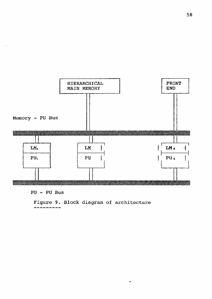
Figure 9. Block diagram of architecture
FRONT END
58
I - LMr: '~ I I
I_ PUr: I
59
Also AND parallelism provides higher parallel degree and
about half or more executed subgoals are evaluable
predicates, and the execution speed of them affects that of
the program. So efficient execution of AND parallelism is
important.
The block diagram of the architecture is shown in
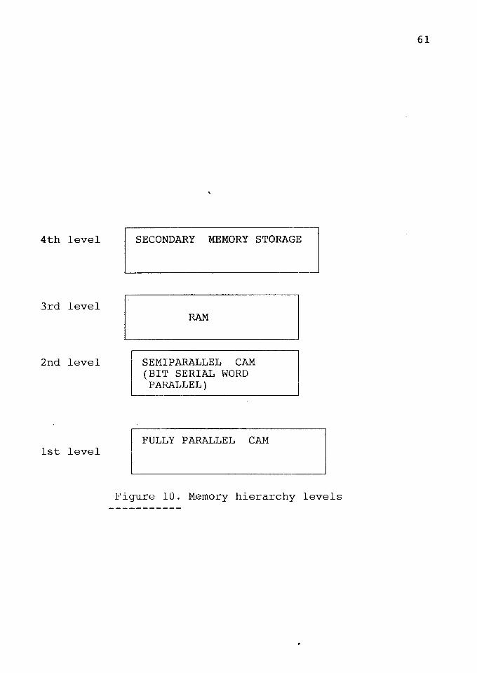
Figure 9. The architecture consists of a memory hierarchy
and several processing units with their own local memories.
The hierarchical memory consists of different CAMs,
with recursive data (which is the largest part of Prolog
programs) stored in a fully parallel CAM. Simple facts are
stored in a semiparallel CAM (bit serial word parallel) and
the remaining types of data are stored in RAM. The rationale
for this type of arrangement is described later on in this
chapter.
In response to a question being asked matching is done
first at this top level and matching rules or facts are
obtained from the main memory. All such matching rules are
then passed on to the literal ordering unit. This unit
decides the order of execution of all literals in the rules
and then all matching rules and facts (clauses) are stored
in a buffer. The literal ordering unit is at the second
level after the main memory.
60
Different units of processing elements make up the
third level. These units each take one clause from the
buffer and start to solve it using AND parallelism. Each
processing unit has a local memory (LM), which is a CAM, and
a few simple processors. These processors are able to talk
with each other via a common internal bus. The literals
which do not share variables can be executed in parallel and
hence two different processing elements can work on two such
literals. The literals that share variables have to be
executed in respective order decided by the ordering rules.
So all such literals are stored in a buffer within the
processing unit. If one processing unit finishes the work
for one of the literals and unsolved literals remain and
dependence conditions are satisfied then it can start
execution on those literals. If there are no such literals
then it has to wait. All processing units operate in the
same fashion.
All the processing units are able to communicate with
each other via an interconnecting bus. Processes can be
transferred from one unit to another if there are no more
clauses in the global buffer and one unit has literals that
need to be solved stored in its internal buffer. Those
literals can be transferred to another unit if they can be
solved in parallel. All the processing elements and the
processing units actively seek work from their internal
4th level
3rd level
2nd level
1st level
SECONDARY MEMORY STORAGE
RAM
SEMIPARALLEL CAM (BIT SERIAL WORD PARALLEL)
FULLY PARALLEL CAM
l
Figure 10. Memory hierarchy levels
61
buffer, the global buffer, or from the other elements and
units.
MEMORY HIERARCHY
62
The memory hierarchy of the design (Figure 10) consists
of two kinds of memories as discussed above, content
addressable and random access. It has been shown by
A.Shanker [l], that there are two kinds of data structures
that are used in Prolog programs. They are known as database
clauses and recursive clauses. The recursive clauses have
the head predicate repeated in the body of the clause. The
database clauses are also known as facts or unit clauses
because they have only one literal in their structure. To
unify the head of the query with the clauses present in
memory faster look up helps. CAM helps in faster look up and
matching. The data structures that are stored in slower
random access memories are neither database or recursive.
Processing elements are divided into groups called
processing units. One processing unit is the master
processing unit and the others are slave units. The master
processing element in the master processing unit starts
execution of a query, and in the process it creates
different OR processes and AND processes. These processes
are stored in the local buffers of the master processor
unit. When there are enough processes, they are picked up by
63
other processing units. Variable bindings are stored in the
local memory of a processing unit. First the bindings of
variables of the master processor are stored in local memory
and when the OR and AND branches are picked up by different
processors they can access to these bindings. The LM also
stores the new bindings made by other processors. It is
assumed here that local memory can serve more than one
processor at one time. When some literals are transferred to
other processing units for unification then the matchings
are transferred from the parent processing unit. The other
processing unit makes all the possible unifications. Some of
these unifications will be thrown away by the parent
processing unit when it receives the results.
With the described arrangement AND execution can be
carried out on a number of processors and hence the
evaluable predicates have more chance for faster evaluation.
This can result in an improvement in program execution
speed.
It is important to look at the mechanism by which the
execution order is decided. This mechanism orders the
execution of subgoals in local buffers. When a processing
unit is finished with a certain subgoal, then it looks for
the next subgoal for execution. This information is
available from the ordering unit, which implements the
ordering mechanism using the ordering of literals for
chapter IV.
64
The analysis of programs by Onai, Shimizu, Masuda and
Moritoshi [21] has shown that unification speed is very
important in improving program execution speed. Content
addressable memories provide faster lookup than random
access memories, it is also shown by the same authors in
their paper [21] that the fraction of database clauses
increases as the database becomes larger and larger. For
unification of database clauses a query must be matched with
the database. Content addressable memory performs matching
very quickly. In content addressable memories the database
is stored in tabulated form and can be searched very fast.
It surely speeds unification and the benefit increases as
the database grows.
Other components in the architecture includes a control
unit and the bus for interprocessing unit communication.
CHAPTER VI
EXECUTION ON PROPOSED ARCHITECTURE
The top level description of the architecture is as
follows. A global memory stores the database needed for
unification. This memory is hierarchical and associative.
There are one or more processing units that access this
memory. Initially, all the data is stored in the global
associative memory. The distribution of data in different
levels of the memory hierarchy is done based upon the
following rules.
1. If the data is of type recursive, then store that in
the recursive unit.
2. If the data is of type fact, then store that in the
semiparallel memory unit.
3. Store everything else in RAM.
The distribution can be done in either hardware or
software. For implementing it in hardware the addresses are
distinguished for different memory units (representing
different hierarchy levels). To implement it in software the
interpreter or compiler decides where the data should be
stored. The fully associative memory acts as a global cache
and recursive data are stored in this unit. The
semiassociative memory unit and RAM make the rest of main
memory for the system. Facts are stored in the
semiassociative memory module. All other data is stored in
RAM.
66
Any query to the system is presented via a front end
computer. This query is then passed on to the master
processing unit. The query is presented to that unit through
the main memory and processing unit communication bus.
After receiving the query the master processing element
starts processing it. The master processing element receives
the query, asks the memory for matching clauses and then
creates AND processes and OR processes.
The main memory responds to a request from the
processing unit by searching and supplying the matching
clauses. All such clauses are stored in a global buffer.
From the global buffer the first clause is selected and the
literals in that clause are ordered.
Then the master PU selects the first matching clause
from the global buffer. First the case of single PU is
considered and actions taken by additional PUs are added
later.
67
It is possible that there can be more than one matching
clause for the query asked. If so, the master processing
unit executes one clause at a time from the global buffer.
When a clause is received, its literals are placed in
processing unit buffers. There are three kind of buffers in
every processing unit. Literals that do not share variables
are stored in the pending buffer. Literals that share
variables are stored in the blocked buffer. The third buffer
is the solved buffer in which all solved literals are
stored. All the literals stored on the pending buffer are
independent and can be processed concurrently.
When a PE takes a literal from the pending buffer for
solution it asks the main memory to supply the matching
literals or rules, and these are stored in the local memory
of the processing unit. The processing element takes the
first matching fact or rule and tries to unify the
variables. Other matching literals are placed in the blocked
or pending buffer depending on shared or unshared variables
respectively. All bindings obtained for the variables are
stored back to local memory and hence they are available for
all other processing elements.
The PEs first take literals (generators of variables)
that are executable and store them on the pending buffer.
If the first literal taken by the master processing
element results in success and there are no other literals
to solve then success is reported to the front end.
68
If there is more than one matching literal then the
first literal (generator of variable) is tried first. After
execution of a generator literal the variables are bound and
if there are any blocked literals that can be executed
simultaneously, they are moved onto the pending buffer and
can be solved concurrently by two different processing
elements.
Whenever a literal from the clause is successfully
unified then it is stored on a solved buffer with its status
as success. If a literal does not get unified successfully
and if this literal is the generator of variable then the
literal ordering algorithm is called again and ordering of
literals is done using some other rule.
If the literal which is the generator of a variable is
unified successfully but other literals for the same clause
fail then backtracking has to be done.
For example, suppose there are 3 literals in the body
of a particular clause, X, Y and z. Assuming X is the
generator of certain variables that are also shared by z but
69
that literal Y does not share any variables with the other
two literals. Then Z is stored on the blocked buffer while X
and Y are stored on the pending buffer.
First the master processing element processes literal
x. Any other processing element can start processing literal
Y. If the attempt for unification for X fails, then the
ordering algorithm is called again and the literals ordered.
If unification for X succeeds, then Z is moved from the
blocked buffer to the pending buffer. In the meantime Y is
processed by some PE. Success for any literal is stored in
the solved buffer. If the attempt for unifying Z fails,
then another matching for Z has to be tried (backtracking).
If there is no other matching, then the unification attempt
for the whole query fails, even though X and Y are
successfully unified.
The important thing is that when the match for a
literal is a rule then the control for that rule stays with
the current processing element. In the above example,
suppose that the generator of all variables is X and that Y
and z share some variables. The master processing element
starts execution on literal X and after successful
unification of X, the variables needed for the execution of
literal Z are bound and hence Z can be processed. In the
70
meantime some other processing element starts execution for
literal Y. Now assuming that there are several matches for
literal Y, each match can be tried in turn until successful
unification occurs.
If a matching literal tried is a rule containing
subgoals then all those subgoals have to be unified
successfully. In this case the processing element that is
executing the literal Y is responsible for obtaining the
final result for the rule for literal Y. This processing
element can spawn different AND and OR processes (for the
subgoals) and put them on their respective buffers. Other
processing elements in that unit can execute the OR
processes for that matching rule for literal Y, and the
processing element which started execution for Y gets the
respective answers.
The master processing element is the parent of the
total clause solution, while the processing element
executing the literal Y is responsible for providing the
answer after the execution of literal Y to the master
processing element. So the master processing element remains
as parent to all the processes. Any other processes created
by the other processing elements report their answer back to
the parent processing element.
71
In the case of more than one processing unit, different
processing units can take different clauses that are
matching the query and can start processing them. In this
way OR parallelism can be exploited at the top level. There
are tradeoffs of having either one processing unit or more
than one processing unit. If there is only one processing
unit then this unit is responsible for the execution of all
different matching clauses. There can be more processing
elements in that processing unit, but then maintaining the
record of which clause is being executed where and
controlling all these processes becomes more complicated.
By having different processing units for the execution
of different clauses, it is assured that there is only one
clause executed in one processing unit at the beginning.
Once some processing unit runs out of work in its local
buffer as well as in the global buffer then it communicates
with other processing units over the interprocessing unit
bus. Different processes can be transferred from one unit to
other via this bus.
Within a processing unit the execution procedure is the
same as described above. Hence OR parallelism is exploited
by all the processing units and AND parallelism is exploited
inside the processing unit.
72
If a processing unit is done with executing all the
literals on both of its buffers, then the processing unit
puts a request for work to other processing units via the
bus. One way of doing that is that a processor in each
processing unit only handles interprocessing unit
communication, i.e., the processor requests control of the
bus and then takes care of transferring literals from other
processing units to its local memory.
When a processing unit puts the request for work on the
bus then there are chances that more than two processing
units have excessive work that can be shared with them and
in such cases the requesting processing unit can get the
work from the processing unit that is closest to it. By
doing so the traffic length on the bus is made shorter.
The forward execution algorithm is called by the
processing unit after it receives the clause from the other
processing unit and ordering of the literals is done.
The backward execution algorithm is invoked when one of
the literals in the clause fails to unify. When two or more
literals share a variable but for that (those) variable(s)
the head of the clause is the generator then OR processes
can be created for them simultaneously (explained in the
detailed example in the previous chapter, chapter IV). But
if any one literal fails in unification then the backward
execution algorithm is called.
73
The processing unit executing a particular literal
which fails is responsible for calling the backward
execution algorithm and as per the algorithm the generation
of new processes is done and new bindings are updated or
stored in the local memory.
It is important that all the information about ordering
of literals should be stored at the beginning of execution
and it is updated as processes are moved from one state to
other. When backtracking is done then the process associated
with a particular literal responsible for failure has to be
tried again. This is determined from the stored information
in the local memory of every processing unit. Some part of
local memory is reserved for storing the order of literals
for a particular clause and the rest of the memory space
stores the binding for different processes.
The other important thing is that when a literal is
moved to another processing unit for execution from the
pending buffer of the parent processing unit then in case of
failure to unify, the new processing unit needs to inform
the parent processing unit. The parent processing unit then
takes control for that literal back.
So, the following algorithms is used to control
backtracking
74
1. If a literal fails, then invoke the backtracking
algorithm; try the process for the innermost literal in the
loop; move the process to the buffer corresponding to its
new state.
2. If the new attempt at the unification fails then
backtrack again.
3. If a literal is moved to another processing unit and it
fails then let the parent processing unit know about it and
send the information back to a parent processing unit;
the processing unit executing that literal stops further
execution of that literal and tries to get another literal
and can work on it; the failed literal is stored back on
buffer in parent processing unit and execution proceeds from
there.
DETAILED EXAMPLE
A example is now presented that covers all the details
for execution. The example presented here is the
same example discussed briefly in chapter IV. (This example
is presented by Conery [6] to describe AND and OR processes,
and here it is used to show how the execution would be
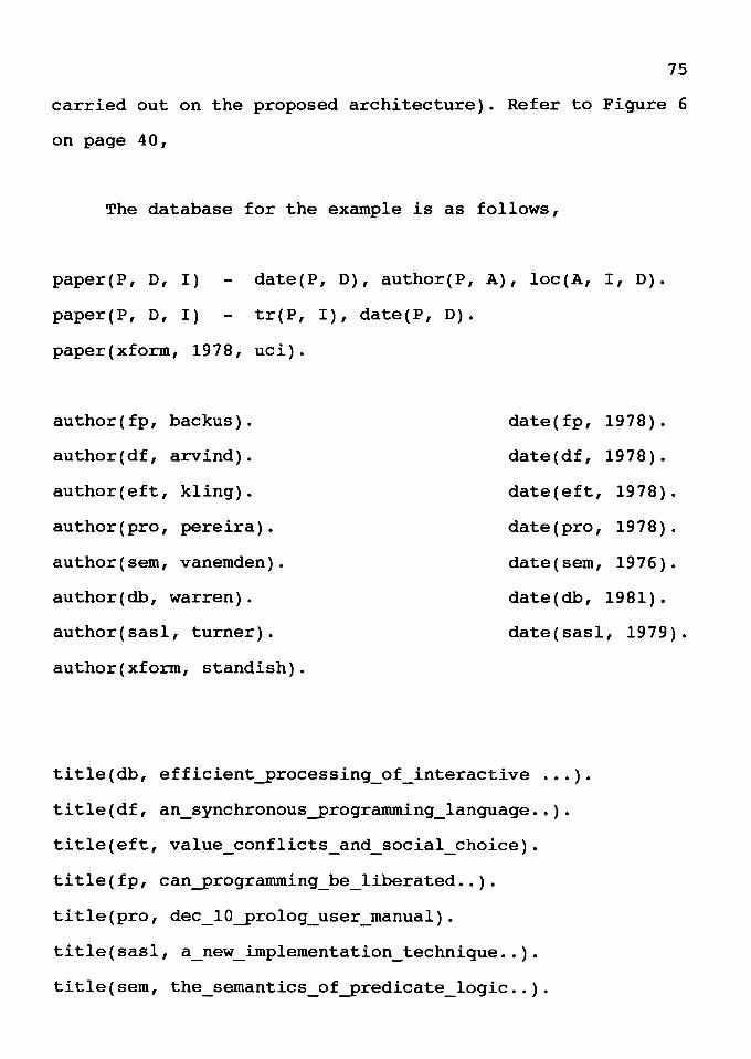
75
carried out on the proposed architecture). Refer to Figure 6
on page 40,
The database for the example is as follows,
paper(P, D, I)
paper(P, D, I)
date(P, D), author(P, A), loc(A, I, D).
tr(P, I), date(P, D).
paper(xform, 1978, uci).
author(fp, backus). date(fp, 1978).
author(df, arvind). date(df, 1978).
author(eft, kling). date(eft, 1978).
author(pro, pereira). date(pro, 1978).
author(sem, vanemden). date(sem, 1976).
author(db, warren). date(db, 1981).
author(sasl, turner). date(sasl, 1979).
author(xform, standish).
title(db, efficient_processing_of_interactive ... ).
title(df, an_synchronous_programming_language .. ).
title(eft, value_conflicts_and_social_choice).
title(fp, can_programming_be_liberated .. ).
title(pro, dec_lO_prolog_user_manual).
title(sasl, a_new_implementation_technique .. ).
title(sem, the_semantics_of_predicate_logic .. ).
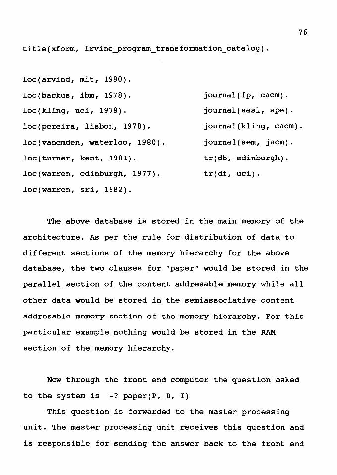
76
title(xform, irvine_program_transformation_catalog).
loc(arvind, mit, 1980).
loc(backus, ibm, 1978).
loc(kling, uci, 1978).
loc(pereira, lisbon, 1978).
loc(vanemden, waterloo, 1980).
loc(turner, kent, 1981).
loc(warren, edinburgh, 1977).
loc(warren, sri, 1982).
journal(fp, cacm).
journal(sasl, spe).
journal(kling, cacm).
journal(sem, jacm).
tr(db, edinburgh).
tr(df, uci).
The above database is stored in the main memory of the
architecture. As per the rule for distribution of data to
different sections of the memory hierarchy for the above
database, the two clauses for "paper" would be stored in the
parallel section of the content addresable memory while all
other data would be stored in the semiassociative content
addresable memory section of the memory hierarchy. For this
particular example nothing would be stored in the RAM
section of the memory hierarchy.
Now through the front end computer the question asked
to the system is -? paper(P, D, I)
This question is forwarded to the master processing
unit. The master processing unit receives this question and
is responsible for sending the answer back to the front end
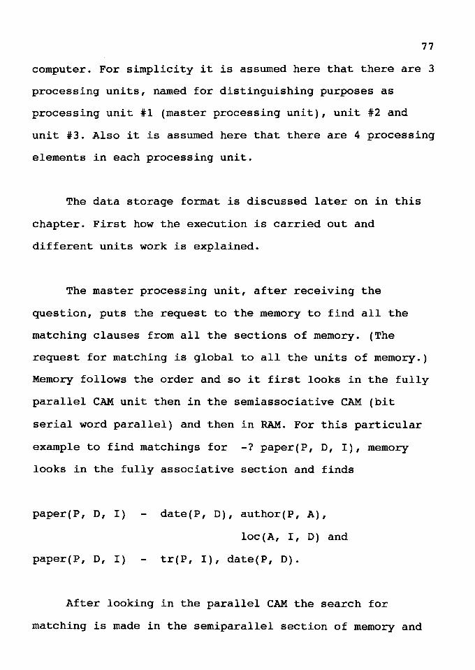
77
computer. For simplicity it is assumed here that there are 3
processing units, named for distinguishing purposes as
processing unit #1 (master processing unit), unit #2 and
unit #3. Also it is assumed here that there are 4 processing
elements in each processing unit.
The data storage format is discussed later on in this
chapter. First how the execution is carried out and
different units work is explained.
The master processing unit, after receiving the
question, puts the request to the memory to find all the
matching clauses from all the sections of memory. (The
request for matching is global to all the units of memory.)
Memory follows the order and so it first looks in the fully
parallel CAM unit then in the semiassociative CAM (bit
serial word parallel) and then in RAM. For this particular
example to find matchings for -? paper(P, D, I), memory
looks in the fully associative section and finds
paper(P, D, I)
paper(P, D, I)
date(P, D), author(P, A),
loc (A, I, D) and
tr(P, I), date(P, D).
After looking in the parallel CAM the search for
matching is made in the semiparallel section of memory and
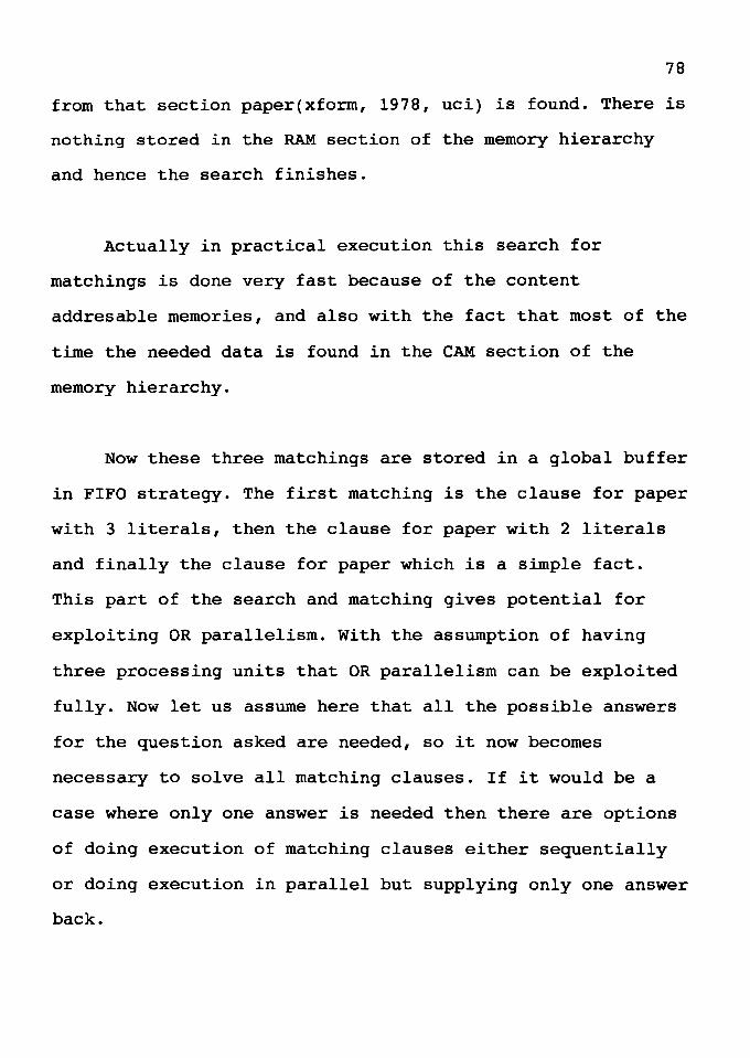
78
from that section paper(xform, 1978, uci) is found. There is
nothing stored in the RAM section of the memory hierarchy
and hence the search finishes.
Actually in practical execution this search for
matchings is done very fast because of the content
addresable memories, and also with the fact that most of the
time the needed data is found in the CAM section of the
memory hierarchy.
Now these three matchings are stored in a global buffer
in FIFO strategy. The first matching is the clause for paper
with 3 literals, then the clause for paper with 2 literals
and finally the clause for paper which is a simple fact.
This part of the search and matching gives potential for
exploiting OR parallelism. With the assumption of having
three processing units that OR parallelism can be exploited
fully. Now let us assume here that all the possible answers
for the question asked are needed, so it now becomes
necessary to solve all matching clauses. If it would be a
case where only one answer is needed then there are options
of doing execution of matching clauses either sequentially
or doing execution in parallel but supplying only one answer
back.
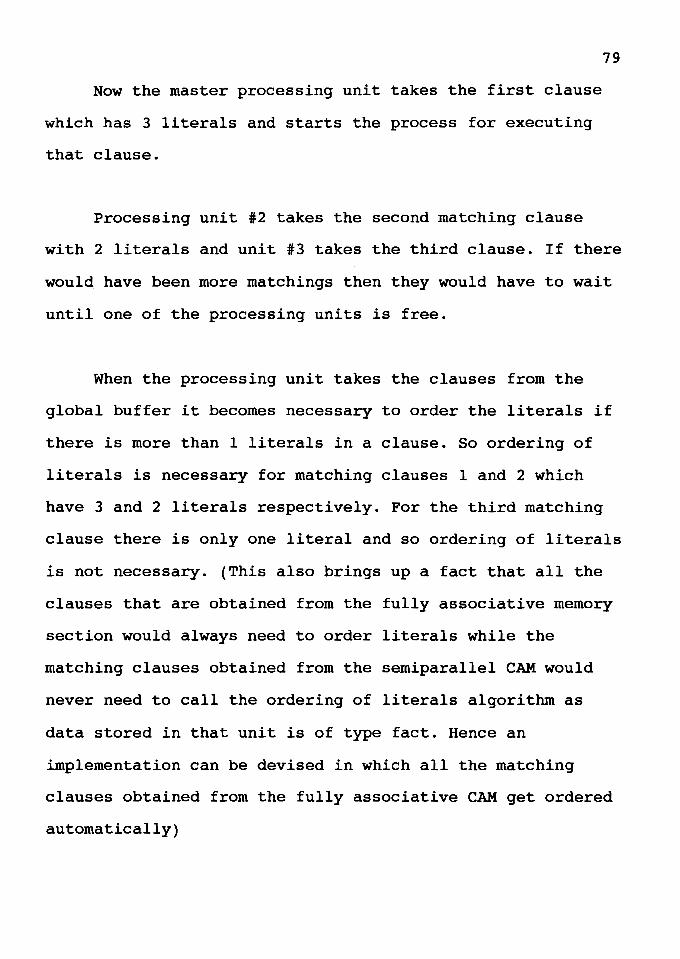
Now the master processing unit takes the first clause
which has 3 literals and starts the process for executing
that clause.
79
Processing unit #2 takes the second matching clause
with 2 literals and unit #3 takes the third clause. If there
would have been more matchings then they would have to wait
until one of the processing units is free.
When the processing unit takes the clauses from the
global buffer it becomes necessary to order the literals if
there is more than 1 literals in a clause. So ordering of
literals is necessary for matching clauses 1 and 2 which
have 3 and 2 literals respectively. For the third matching
clause there is only one literal and so ordering of literals
is not necessary. (This also brings up a fact that all the
clauses that are obtained from the fully associative memory
section would always need to order literals while the
matching clauses obtained from the semiparallel CAM would
never need to call the ordering of literals algorithm as
data stored in that unit is of type fact. Hence an
implementation can be devised in which all the matching
clauses obtained from the fully associative CAM get ordered
automatically)
80
After ordering of literals for the processing unit #1,
the head goal is paper(P, D, I), the literals are
date(P, D), author(P, A) and loc(A, I, D).
The set of variables that have a generator is
G = {P, D, I}. The set which contains variables for which a
generator is not specified is U = {A}. Now the connection
rule is used to search through the clause, and the
connection rule decides the generator for a variable if that
variable is present with another variable in a literal but
the other variable has its generator already decided. So for
the variable A the literal loc(A, I, D) becomes the
generator as loc has two other variables that have the head
of the goal designated as their generator.
So the order of literals will be, date as literal #1,
loc as literal #2 and author as literal #3. For date and loc
there is one common variable, D. If the head goal would have
some value to bind this literal then OR processes for both
literals could have been started but in this case the head
variable does not bind variable D to any value and hence the
execution of literal loc has to wait until literal date
binds variable D to some value. The date literal is moved to
the pending buffer and the other two literals are moved to
the blocked buffer as they have to wait until execution for
date is completed.
81
Looking into the database it becomes clear that there
are many matching literals for date and loc and the main
memory provides these matchings to the local memory of the
processing unit. The first matching for literal date from
the local memory would be date(fp, 1978), binding variable P
to fp and variable D to 1978. This binding is stored in the
local memory of the processing unit. The controlling unit
senses the binding of variable D to value 1978 and moves the
loc literal to the executable state (pending state).
The processing element that executes the literal loc
gets the first binding as loc(backus, ibm, 1978). At this
point variable A is bound to backus and variable I is bound
to ibm. The execution of literal author is now possible and
the matching found from the local memory would be
author(fp, backus). The execution ends in success. The
important thing in this part of the example is that
execution has to be carried on sequentially because all
literals share the variables and no variable was bound to
any value by the head goal.
If the question asked was
-? paper(P, 1978, uci)
the variable D would be bound to the value 1978 and in
that case the pending buffer would have two literals, date
82
and loc, ready for execution and the blocked buffer will
have the literal author. So two processing elements can
start execution on literals date and loc. In that case the
execution for date would bind P to fp, D is already bound to
1978 and execution of loc (carried out simultaneously with
date) would bind A to kling and I is already bound to uci.
There is no matching literal for author(fp, kling) in the
database and hence author fails and backtracking has to be
performed. The backtracking algorithm would be called and
literal loc would be tried again. But loc would fail
immediately as there is no other binding for A with D and I
bound to 1978 and uci respectively. So again backtracking
will be done and date would be tried again. It turns out
that when P is bound to eft then the execution of the goal
would succeed.
A very important thing here is that when a processing
element takes the literal date for execution there is more
than one matching available from local memory. The decision
to try the first matching and if that fails then try the
second matching is one way of doing it. The other way to do
this is to move all matching date literals on the pending
buffer and hence the other idle processing elements can try
them one after the other and the different bindings can be
stored in local memory in FIFO order. When needed they can
be obtained from the local memory and no time is lost at
83
that point. This method is very efficient when all possible
solutions are needed in response to the query asked. It may
not be a good way to solve all matching literals when only
one answer is needed.
The same way of processing is used in unit #2. Literals
tr and date are stored on the blocked buffer as they share
variable P. The first execution cycle gives the final answer
as tr(db, edinburgh) and date(db, 1981). In case of the
query paper(P, 1978, uci), the variable Pis not bound by
the head goal and hence execution proceeds sequentially. The
final result in this case will be date(df, 1978) and tr(df,
uci).
In processing unit #3 the execution is very simple and
variable P is bound to xform, while D to 1978 and I to uci.
The results from all the three units are then given back to
the front end computer and the execution ends there.
There are some details to discuss for the way things
are carried out for execution, e.g.,how the communication
between processing unit and the memory is done. It is
mentioned that a processing element from a processing unit
asks the memory to search and supply all the matching
clauses and then memory replies back to that processing
element. The communication at this level needs some more
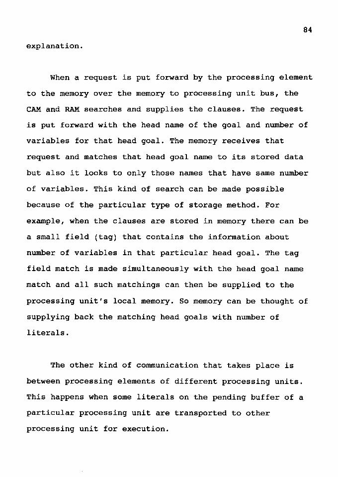
84
explanation.
When a request is put forward by the processing element
to the memory over the memory to processing unit bus, the
CAM and RAM searches and supplies the clauses. The request
is put forward with the head name of the goal and number of
variables for that head goal. The memory receives that
request and matches that head goal name to its stored data
but also it looks to only those names that have same number
of variables. This kind of search can be made possible
because of the particular type of storage method. For
example, when the clauses are stored in memory there can be
a small field (tag) that contains the information about
number of variables in that particular head goal. The tag
field match is made simultaneously with the head goal name
match and all such matchings can then be supplied to the
processing unit's local memory. So memory can be thought of
supplying back the matching head goals with number of
literals.
The other kind of communication that takes place is
between processing elements of different processing units.
This happens when some literals on the pending buffer of a
particular processing unit are transported to other
processing unit for execution.
85
In such case a large amount of information gets
transferred between two processing elements. The processing
unit asking for work puts the request on the bus and that
request is received by all the PUs (processing units). The
PU which is closer physically to the "hungry" PU gets the
first priority for sending work. The parent PU sends the
work to the other PU from the pending buffer. The
information sent from the parent PU contains the total
number of literals sent, the matching literals, and most
importantly the parent PU's address so the answers can be
sent back to the parent PU. Also the parent unit keeps note
of what literals are sent to which PU. In cases when work is
sent to other units and results come back to the parent unit
then the processing element which is executing the clause
looks for results in the solved buffer, which stores all
such results. In this way the PE (processing element) can
find answers.
Things start to become complicated when communication
and execution of literals is done at another unit. The work
sent is literals to be executed with their matching literal
database from the local memory of the sender and the answer
sent back is bindings of variables for literals and the
success or failure message.

86
The communication between a PE and the local memory is
of the same nature as that of main memory and a processing
element at the beginning of execution.
CHAPTER VII
RESULT AND ANALYSIS
To analyze and evaluate the proposed design the
architecture was parameterized as described here. Main
memory is assumed to have either one or two ports. There are
two buses in the architecture, with one bus supporting
communication between main memory and PUs and the other bus
supporting communication between different PUs. Also, the
communication time between main memory and the PUs and
between PUs are set to two different values. Communication
time is the total of the time needed to transfer work, to
calculate the result and to send the result back to the
parent PU.
There can be different configurations depending on the
number of PUs and the number of PEs and the parameters
described above. An architecture with m PUs and n PEs per PU
is classified as m * n. Execution time results are obtained
for different configurations and they are then compared to
draw conclusions.
Some assumptions are made for the analysis of the
architecture. First, the main memory is assumed to be large
BB
enough to hold the entire database, i.e., secondary memory
is not required. Second, the local memory is assumed to
store all local information so that local information does
not have to be stored in main memory. Third, it is assumed
that the access time for the local buffers is independent of
the number of PEs in a PU.
One of the test programs chosen is the benchmark
program "query" (Appendix 1), which has potential for both
AND and OR parallelism. This program is selected because it
is a database dependent program with easily traceable AND
and OR parallelism. This helps in mapping it to different
configurations of the architecture. The second test program
"coloring of map" (Appendix 1), is chosen because it
contains goals that fail, so the use of multiple solutions
is important.
The results are obtained by performing hand simulation
(assigning different goals to different processing elements
in different PUs) and the time is calculated in number of
cycles including memory time. All the results are optimized
for every configuration and the results for different
configurations obtained are a function of the parameters m,
n, time for main memory bus, time for PU - PU bus, and
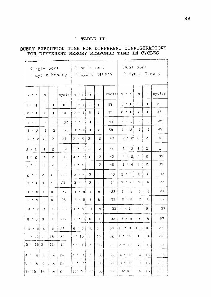
TABLE II
QUERY EXECUTION TIME FOR DIFFERENT CONFIGURATIONS FOR DIFFERENT MEMORY RESPONSE TIME IN CYCLES
Single port Single port Dual port
1 cycle Meriory 2 cycle Meriory 2 cycle Meri or y
f'1 • n f'1 n eye le' f'1 • n f'1 n cycle f'1 • n rl n cycles
l . 1 1 l 82 l . 1 J 1 89 1 . 1 1 l 82
2 • 1 2 1 48 2 • 1 2 1 89 2 • 1 2 l 48
4 • J 4 l 37 4 • l 4 1 44 4 • 1 4 J 40
1 • 2 J 2 51 J • 2 1 2 58 l • 2 l 2 49
2 • 2 2 2 41 2 • 2 2 2 48 2 • 2 2 2 41
3 • 2 3 2 39 3 • 2 3 2 46 3 • 2 3 2 -
4 • 2 4 2 35 4 • 2 4 2 42 4 • 2 4 2 33
1 • 4 1 4 35 1 • 4 1 2 42 1 • 4 1 2 33
2 • 4 2 4 33 2 • 4 2 4 40 2 • 4 2 4 32
3 • 4 3 4 27 3 • 4 3 4 34 3 • 4 3 4 27
1 • 8 l 8 26 1 • 8 1 8 33 1 • 8 I 8 27
2 • 8 2 8 26 2 • 8 2 8 33 2 • 8 2 8 27
4 8 4 81 26 4 • 8 4 8 33 4 • 8 4 8 27
8 • 8 8 8 26 8 • 8 8 8 33 8 • 8 8 8 27
15 • el 15 8 26 16 • 8 16 8 33 16 • 8 16 8 27
1 16 1 16 24 J . 16 1 16 32 1 . 16 J 16 23
2 16 2 J 5 24 2 • 16 2 161 32 2 • 16 2 16 23
4 . i6 4 16 24 4 • 16 4 161 32 4 • 16 4 16 23
8 • 16 8 , 16 24 8 • J 6 8 16 32 8 • 16 8 16 23
is· 16 16 16 24 is· 16 16 161 32 1s·16 16 16 23
89
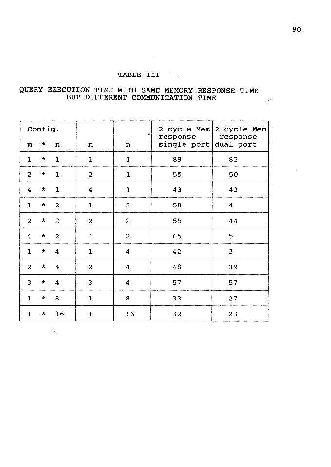
TABLE III
QUERY EXECUTION TIME WITH SAME MEMORY RESPONSE TIME BUT DIFFERENT COMMUNICATION TIME
~
Config. 2 cycle Mem 2 cycle Mem ' response response
m * n m n single port dual port
1 * 1 1 1 89 82
2 * 1 2 1 55 50
4 * 1 4 1 43 43
1 * 2 1 2 58 4
2 * 2 2 2 55 44
4 * 2 4 2 65 5
1 * 4 1 4 42 3
2 * 4 2 4 48 39
3 * 4 3 4 57 57
1 * 8 1 8 33 27
1 * 16 1 16 32 23
90
91
the number of main memory ports.
The results obtained from the first test program are
very interesting (Tables II and III). As expected, the
performance of sequential processing is the poorest of all
the configurations. The speed of execution increases as the
number of PEs is increased. Speed also increases with an
increase in the number of PUs. The results can be presented
in different ways, for example increasing the number of PEs
but keeping the number of PUs constant, keeping the number
of PEs the same but increasing the number of PUs, comparing
all the results with the sequential execution time with only
one PE. Figure 11 (graph 1) shows results for the first
class, figure 12 (graph 2) shows example results for the
second class.
The highest speedup is obtained when there is only one
PU and the number of PEs in that PU is increased. This is
interesting because the communication time is totally
absent, as there is only one processing unit. But it is
assumed here that the pending and blocked buffers are able
to support multiple PEs at the same time inside the
processing unit. The performance is also improved when the
number of PUs is increased, but after reaching a certain
point the saturation in speedup is reached and then
increasing the number of PUs does not increase the
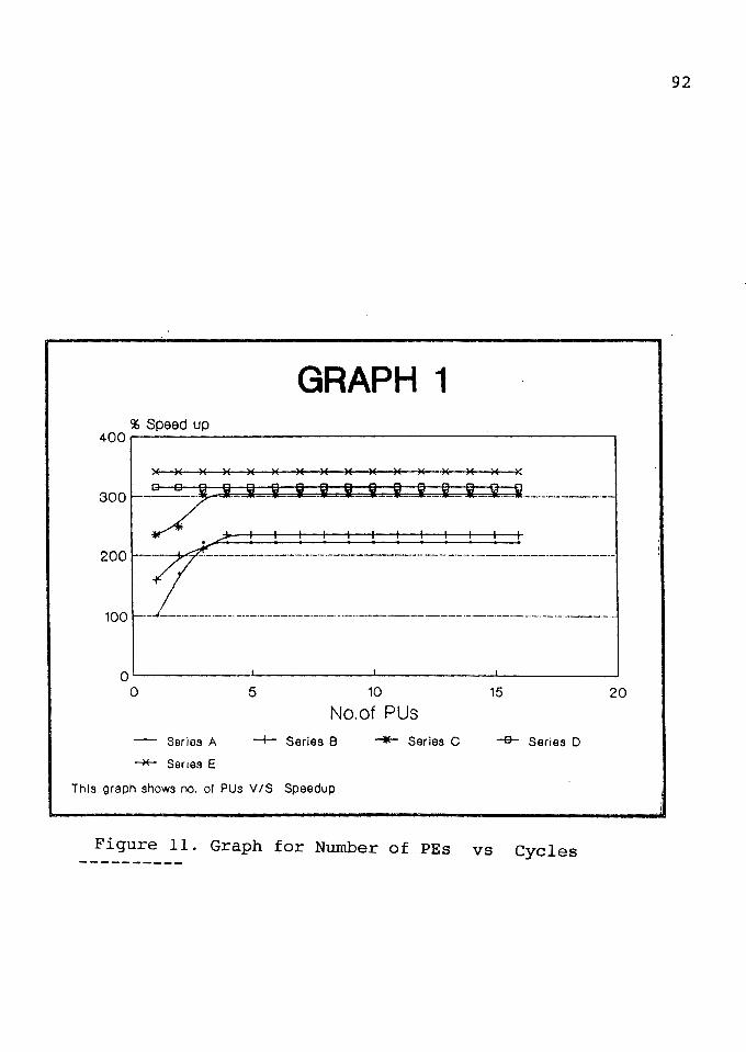
GRAPH 1 % ~~s~p~e~ed~u~p~~~~~~~~~~~~~~~~~~~---,
400~
)( )( )( )( )( )( )( )( )( )( )( )( )( )( )( )(
300 - -- - __ - ·- --- ---i :J= iAL .i=_ i .. :2. JI
200
7j; jj Ji: L;IL:j; ______ -- - - - - - -
-'l~ _ _!__!__~---~~_!__-----'_! ___ ' _ _!__' _________ _
100 --'----·-·-·--------·-·----·-------·--------·-----------·--·-··-·.:.·--------·-----·---·
0 0
- Series A
--*- Series E
5 10
No.of PUs -t- Series 8 """*-- Series C
This graph shows no. ol PUs Y /S Speedup
15
-a- Series D
Figure 11. Graph for Number of PEs vs Cycles
20
92
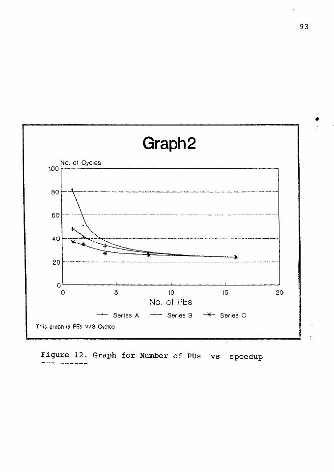
93
•
Graph2 No. of Cycles
100~~~.:__~~~~~~~~~~~~~~~~-:-~~~~-,
so~·
50 ,_ ________ , ·- -- -·-· ·- _ .... ----·-·- -· .. ------------------·-·-----.. ·---·--··-·-·--. -·-·-·-·-··-·- _________ .. __________ . ________ .. _ ·-
40
20 >--·-·-----·-·--·------------·-··-·-----------------·------·----------·--·-··-----··-··-·-·-·--·---·-·---·-·-
Q'--~~~~_._~~~~~..._~~~~-'-~~~~--'
0 5 10 15 20
No. of PEs
- Series A -t- Series B -*-- Series C
This graph is PEs VIS Cycles
Figure 12. Graph for Number of PUs vs speedup
94
performance further. Similarly the saturation in speed is
also reached after a certain number of PEs inside a single
PU. In fact, keeping all the PEs in one PU is better than
dividing them among several PUs as communication affects the
speed of execution.
The results for the map coloring problem are also
interesting. The solution obtain with one processor and one
processing unit takes about 42 cycles. The configuration of
architecture with 2 processing unit each having 4 processing
units takes about 19 cycles. The speedup obtained with 2 PUs
and 4 PEs inside one PU is 221 % faster than sequential
execution.
DIFFERENCE BETWEEN BENCHMARK PROGRAMS
The difference between the two programs selected for
analysis is discussed here. The map coloring program has all
the AND goals and then the OR subgoals for AND goals are
spawned. So initially all the AND goals (a total of 4 at the
bottom row in the graph in Figure 7 in chapter IV) are
blocked. In the query program two AND subgoals are blocked
initially. The number of OR subgoals is higher in the query
program and hence the work that can be transferred to other
units is great. There is not enough work to transfer to
other units in the map coloring program. Hence a
configuration which has PEs in only one PU is more suitable
95
for the map coloring problem than the same number of PEs
distributed over multiple PUs. The advantage with a similar
configuration for the query program exists but it is not as
evident as in the map coloring problem. In the map coloring
problem the extra work (binding of a region to more than one
color) is done and is then not utilized, while in the query
program no extra work is done and efforts are not wasted.
The results have allowed us to conclude that the
architecture and execution algorithm increase the
performance greatly, in some cases by as much as 300 %
compared to sequential execution.
CHAPTER VIII
FUTURE WORK AND CONCLUSIONS
There are some issues that were left out of the
analysis but are too important to ignore for an actual
implementation purpose. It would be worthwhile to explore
these issues in the future to get more accurate results.
Issues to be explored include the following. First, the
response time of the memory system when needed data is not
found and has to be retrieved from the secondary memory.
Second, the limitation on the number of PEs that can be
served at a particular time by the pending and blocked
buffers would seriously affect the time it takes to solve a
particular goal. Finally, when there are enough goals to be
transferred to other PUs and communication increases, then
the PU - PU bus may become a bottleneck and so other
communication methods may be needed.
One of the future goals might be to develop an
interpreter that would be helpful for actual simulation of
the results. The interpreter would be responsible for the
execution algorithms and goal ordering also. The proposed
architecture should be tested on other benchmark programs to
get more accurate results about the overall performance. A
97
simulation done with the use of the interpreter will provide
different results and these results can be compared.
CONCLUSION
The work presented here covered different types of
parallelisms in logic programs, an introduction to Prolog,
other logic programming languages and their origins, a brief
description of other attempts to exploit parallelism in
Prolog, the method used here to exploit parallelism in
Prolog, the structure of an architecture to carry out the
work and make use of parallelism present in Prolog, the
parametrization of the architecture, analysis with
assumptions and finally results obtained showing the
performance of the architecture.
It is shown in this thesis that AND parallelism is an
important source of parallelism [21] and unification speed
affects the overall speed [l]. The proposed architecture
design is able to exploit the AND parallelism and has the
capability for faster unifications and reduced total
execution time (Tables II,III).
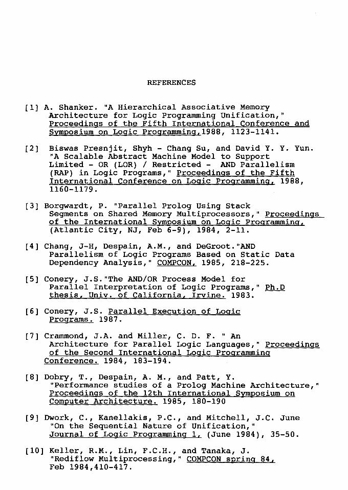
REFERENCES
[l] A. Shanker. "A Hierarchical Associative Memory Architecture for Logic Programming Unification," Proceedings of the Fifth International Conference and Symposium on Logic Programming,1988, 1123-1141.
[2] Biswas Presnjit, Shyh - Chang Su, and David Y. Y. Yun. "A Scalable Abstract Machine Model to Support Limited - OR (LOR) I Restricted - AND Parallelism (RAP) in Logic Programs," Proceedings of the Fifth International Conference on Logic Programming, 1988, 1160-1179.
[3] Borgwardt, P. "Parallel Prolog Using Stack Segments on Shared Memory Multiprocessors," Proceedinas of the International Symposium on Logic Programming, (Atlantic City, NJ, Feb 6-9), 1984, 2-11.
[4] Chang, J-H, Despain, A.M., and DeGroot."AND Parallelism of Logic Programs Based on Static Data Dependency Analysis," COMPCON, 1985, 218-225.
[5] Conery, J.S."The AND/OR Process Model for Parallel Interpretation of Logic Programs," Ph.D thesis, Univ. of California, Irvine. 1983.
[6] Conery, J.S. Parallel Execution of Logic Programs. 1987.
[7] Crammond, J.A. and Miller, C. D. F. " An Architecture for Parallel Logic Languages," Proceedings of the Second International Logic Programming
Conference. 1984, 183-194.
[8] Dobry, T., Despain, A. M., and Patt, Y. "Performance studies of a Prolog Machine Architecture," Proceedings of the 12th International Symposium on Computer Architecture. 1985, 180-190
[9] Dwork, C., Kanellakis, P.C., and Mitchell, J.C. June "On the Sequential Nature of Unification," Journal of Logic Programming l, (June 1984), 35-50.
[10] Keller, R.M., Lin, F.C.H., and Tanaka, J. "Rediflow Multiprocessing," COMPCON spring 84, Feb 1984,410-417.
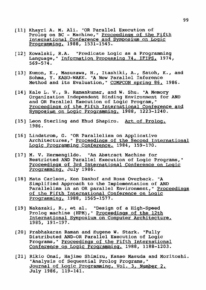
[ll] Khayri A. M. Ali. "OR Parallel Execution of Prolog on BC - Machine," Proceedings of the Fifth International Conference and Symposium on Logic Programming, 1988, 1531-1545.
[12] Kowalski, R.A. "Predicate Logic as a Programming Language," Information Processing 74, IFIPS, 1974, 569-574.
[13] Kuman, K., Masuzawa, H., Itashiki, A., Satoh, K., and Sohma, Y. KABU-WAKE. "A New Parallel Inference
99
Method and its Evaluation," COMPCON spring 86, 1986.
[14] Kale L. v., B. Ramankumar, and W. Shu. "A Memory Organization Independent Binding Environment for AND and OR Parallel Execution of Logic Program," Proceedings of the Fifth International Conference and Symposium on Logic Programming, 1988, 1223-1240.
[15] Leon Sterling and Ehud Shapiro. Art of Prolog. 1986.
[16] Lindstrom, G. "OR Parallelism on Applicative Architectures," Proceedings of the Second International Logic Programming Conference, 1984, 159-170.
[17] M. v. Hermengildo. "An Abstract Machine for Restricted AND Parallel Execution of Logic Programs," Proceedings of 3rd International Conference on Logic Programming, July 1986.
[18] Mats Carlson, Ken Danhof and Ross Overback. "A Simplified Approach to the Implementation of AND Parallelism in an OR parallel Environment," Proceedings of the Fifth International Conference on Logic Programming, 1988, 1565-1577.
[19] Nakazaki, R., et al. "Design of a High-Speed Prolog machine (HPM)," Proceedings of the 12th International Symposium on Computer Architecture, 1985, 191-197.
[20] Prabhakaran Raman and Eugene w. Stark. "Fully Distributed AND-OR Parallel Execution of Logic Programs," Proceedings of the Fifth International Conference on Logic Programming, 1988, 1188-1203.
[21] Rikio Onai, Hajime Shimizu, Kanae Masuda and Moritoshi. "Analysis of Sequential Prolog Programs," Journal of Logic Programming, Vol. 3, Number 2, July 1986, 119-141.
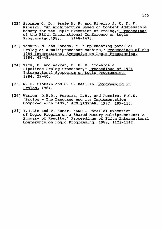
100
[22] Storman c. o., Brule M. R. and Ribeiro J. C. o. F. Ribeiro. "An Architecture Based on Content Addressable Memory for the Rapid Execution of Prolog," Proceedings of the Fifth International Conference on Logic Progranuning,1988, 1448-1473.
[23] Tamura, N. and Kaneda, Y. "Implementing parallel Prolog on a multiprocessor machine," Proceedings of the 1984 International Symposium on Logic Progranuning, 1984, 42-48.
[24] Tick, E. and Warren, o. H. D. "Towards a Pipelined Prolog Processor," Proceedings of 1984 International Symposium on Logic Progranuning, 1984, 29-40.
[25] W. F. Cloksin and C. s. Mellish. Programming in Prolog, 1984.
[26] Warren, D.H.D., Pereira, L.M., and Pereira, F.C.N. "Prolog - The Language and its Implementation Compared with LISP," ACM SIGPLAN, 1977, 109-115.
[27] Y.J.Lin and V. Kumar. "AND - Parallel Execution of Logic Program on a Shared Memory Multiprocessor: A Summary of Results," Proceedings of Fifth International Conference on Logic Programming, 1988, 1123-1142.
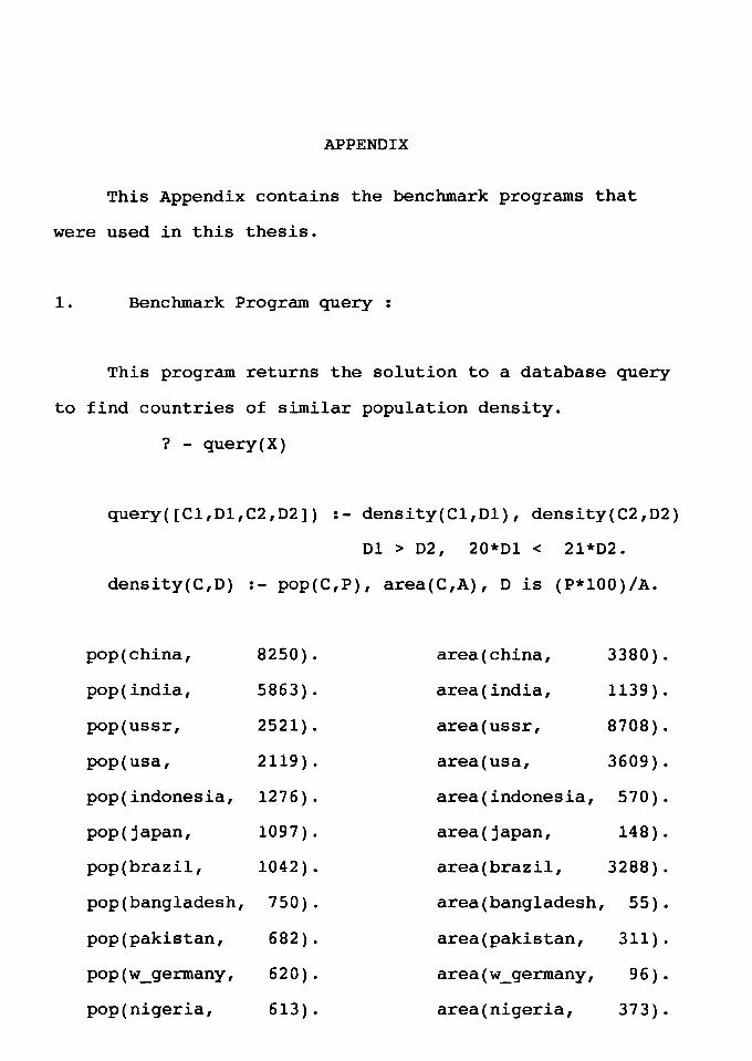
APPENDIX
This Appendix contains the benchmark programs that
were used in this thesis.
1. Benchmark Program query :
This program returns the solution to a database query
to find countries of similar population density.
? - query(X)
query([Cl,Dl,C2,D2]) :- density(Cl,Dl), density(C2,D2)
01 > 02, 20*01 < 21*02.
density(C,D) :- pop(C,P), area(C,A), Dis (P*lOO)/A.
pop(china, 8250). area(china, 3380).
pop(india, 5863). area(india, 1139).
pop(ussr, 2521). area(ussr, 8708).
pop(usa, 2119). area(usa, 3609).
pop(indonesia, 127 6) . area(indonesia, 570).
pop( japan, 1097) . area(japan, 148).
pop(brazil, 1042). area(brazil, 3288).
pop(bangladesh, 7 50) . area(bangladesh, 55).
pop(pakistan, 682). area(pakistan, 311).
pop(w_germany, 620). area(w_germany, 96) .
pop(nigeria, 613) . area(nigeria, 373).
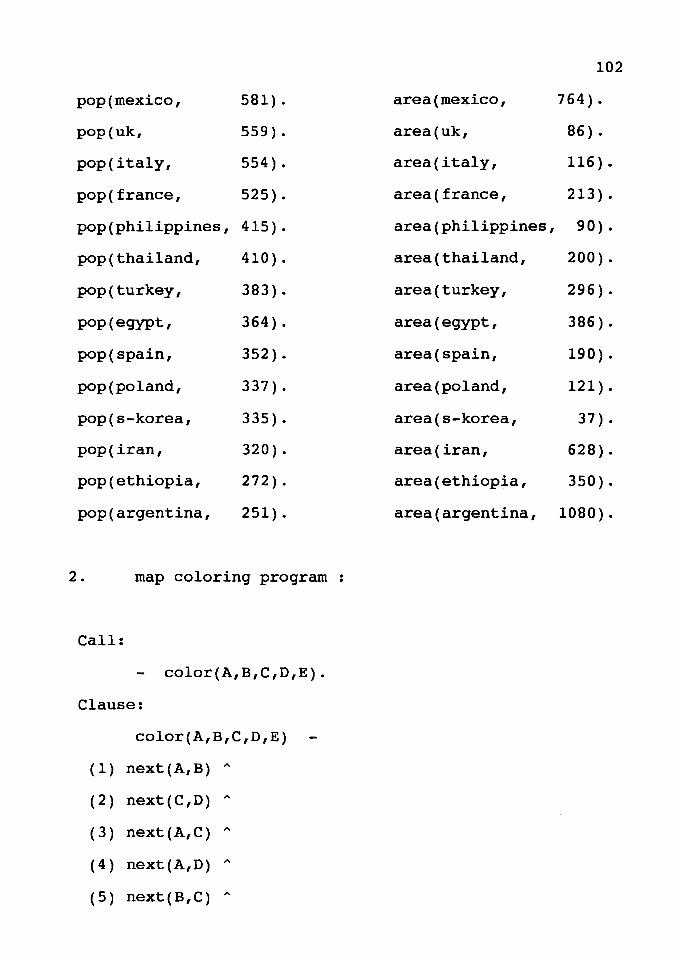
102
pop(mexico, 581). area(mexico, 764).
pop(uk, 559). area(uk, 86) .
pop(italy, 554). area(italy, 116).
pop(france, 525). area(france, 213).
pop(philippines, 415). area(philippines, 90) .
pop(thailand, 410). area(thailand, 200).
pop(turkey, 383). area(turkey, 296).
pop(egypt, 364). area(egypt, 386).
pop(spain, 352). area(spain, 190).
pop(poland, 337) . area(poland, 121).
pop(s-korea, 335). area(s-korea, 37) .
pop(iran, 320). area(iran, 628).
pop(ethiopia, 272) . area(ethiopia, 350).
pop(argentina, 251). area(argentina, 1080) .
2. map coloring program
Call:
color(A,B,C,D,E).
Clause:
color(A,B,C,D,E)
(1) next(A,B) "
( 2 ) next { C , D) "
( 3) next (A, C) "
(4) next(A,D) "
( 5 ) next ( B, C ) "
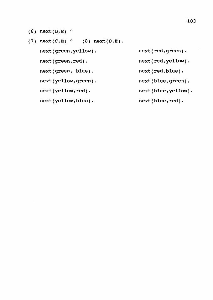
( 6 ) next ( B, E ) "
( 7 ) next ( C , E ) " ( B ) next ( D , E ) .
next(green,yellow).
next(green,red).
next(green, blue).
next(yellow,green).
next(yellow,red).
next(yellow,blue).
103
next (red, green) .
next(red,yellow).
next(red.blue).
next(blue,green).
next(blue,yellow).
next(blue ,red).