Embed Size (px)
Citation preview

Noname manuscript No.(will be inserted by the editor)
Exploiting DLP Illumination Dithering forReconstruction and Photography of High-speed Scenes
Sanjeev J. Koppal · Shuntaro Yamazaki · Srinivasa G. Narasimhan
Received: — / Accepted: —
Abstract In this work, we recover fast moving scenes
by exploiting the high-speed illumination “dithering”
of cheap and easily available digital light processing
(DLP) projectors. We first show how to reverse-engineer
the temporal dithering for off-the-shelf projectors, us-
ing a high-speed camera. DLP dithering can produce
temporal patterns commonly used in active vision tech-
niques. Since the dithering occurs at a very high frame-
rate, such illumination-based methods can be “sped up”
for fast scenes. We demonstrate this with three applica-
tions, each of which only requires a single slide to be dis-
played by the DLP projector. The quality of the result
is determined by the camera frame-rate available to the
user. Pairing a high-speed camera and a DLP projec-
tor, we demonstrate structured light reconstruction at
100Hz. With the same camera and three or more DLP
projectors, we show photometric stereo and demulti-
plexing applications at 300Hz. Finally, with a real-time(60 Hz) or still camera, we show that DLP illuminationacts as a very fast flash, allowing strobe photography of
high-speed scenes. We discuss, in depth, some charac-
teristics of the temporal dithering with a case study of
This is an extension and consolidation of our previous work onthe active vision systems using DLP projectors ([24],[16]).
Srinivasa G. Narasimhan and Sanjeev J. Koppal
The Robotics Institute, Carnegie Mellon University, USA
Tel.: +1-412-268-3818Fax.: +1-412-268-6436E-mail: [email protected],[email protected]
Shuntaro YamazakiNational Institute of Advanced Industrial Science and Technol-ogy, JapanTel.: +81-3-3599-8358Fax.: +81-3-5530-2066E-mail: [email protected]
a particular projector. Finally, we describe limitations,
trade-offs and other issues relating to this work.
Keywords Active Vision · DMD · DLP · High Speed
Camera · Temporal Dithering
1 Introduction
Illumination changes create powerful visual cues. These
are widely exploited in computer vision and graphics for
scene analysis. Photometric lighting-based techniques
first choose a reflectance model and then estimate its
parameters from images taken under varying lighting.
This is the basis for classical photometric stereo ([45])for lambertian scenes, as well as several extensions fornon-lambertian low parameter BRDFs. However, most
of these methods rely on changes in light-source loca-
tion or direction. Instead, there are other approaches
that employ temporal or spatial modulation of the in-
cident light-field. These techniques obtain correspon-
dences between the light source and the camera to re-cover scene properties (such as scene depths [44]).
In this paper, we are interested in analyzing high-
speed scenes, imaged at faster-than-real-time rates (≥
120Hz). Almost all of the correspondence-based lightingtechniques described above avoid the difficult problemof tracking moving scene points. Instead, these require
that the illumination modulation occurs at a much faster
rate than scene motion. This means that during image
capture, the scene must be essentially static. Most rea-
sonably fast scenes quickly outpace physical methods of
moving or modulating the light-source, such as hand-
waving or shifting attenuating masks.
This would suggest that high-speed scene analysis
should be performed only with passive techniques, such
as multi-view stereo, by using high-frame rate cameras.
2
Although very expensive, today such cameras can cap-
ture video at speeds up to 10000Hz. However, two prob-
lems exist with passive methods. First, there are vari-
ous types of scene information (such as high-resolution
surface normals from photometric stereo, and direct-
indirect components from fast separation [26]) which
cannot be obtained purely by using cameras. Second,
since camera motion would be much slower than scene
motion, multiple viewpoints would be required. This
would imply additional cameras, increasing the already
prohibitive cost.
Therefore, in this work, we focus on speeding up ac-
tive vision techniques for fast scenes. Our approach is
to rely on electronic means of controlling illumination.
Such computer controlled illumination would modulate
the light much faster than the scene motion. One way todo this would be to use LCDs (liquid crystal displays)[49] which can modulate illumination at real time (60-
120 Hz) rates. However, for faster scenes, as those de-
picted in our work, most LCDs simply do not change
quickly enough. In addition, at higher speeds, they ex-
hibit SNR issues for image capture, since the incident
light is attenuated.
Recently, a MEMS device called the Digital Mi-
cromirror Device (DMD) has been introduced to mod-
ulate illumination. Each mirror in the DMD is 14× 14
microns and can switch between two orientations, +12o
and −12o [8]. In one orientation, incident light is re-
flected by the mirror toward the outside scene and in
the other, light is reflected onto a black surface withinthe projector. These mirrors can switch between orien-tations in a few microseconds, enabling high precisioncontrol of illumination. As a result, the DMD device
has found applications in areas ranging widely from mi-
croscopy to chemistry to holographic displays [8].
However, DMD kits that allow total control andprogrammability of the incident illumination are al-
most as expensive as high-speed cameras, making theiruse for high-speed scene analysis difficult. Our key in-sight was to note that an integral component of allDigital Light Processing (DLP) technology projectors
(http://www.dlp.com) is also a DMD chip. Therefore
DLP technology has enabled mass production of low
cost DMD chips with one drawback: we cannot directly
control the mirror states of the DMD chip. However,we can control the slides that the projector will emit.
This paper investigates techniques to reverse-engineer
and exploit cheap, off-the-shelf DLP projectors for fast
active vision.
1.1 Related work
Projectors are commonly used as programmable light
sources for a variety of active vision techniques includ-
ing structured light reconstruction [44,48,7,6,47,37],
photometry-based scene recovery [52,11], relighting [43],
light transport analysis [26,39] and depth from defocus
[50]. The intensity and color of the scene’s illumination
can be controlled over space and time depending on the
task at hand. For instance, projecting a set of colored
striped patterns onto a scene alleviates the problem of
finding correspondences for 3D reconstruction [48].
The operating principle of the DMD device has also
been exploited in computer vision and graphics. Nayar
et al. [25] re-engineer a DLP projector into a DMD-
camera and demonstrate the notion of programmable
imaging for applications including adaptive dynamic
range and optical filtering and matching. Based on the
theory of compressive sampling, a single pixel camerahas been implemented where the DMD device is usedto compute optical projections of scene radiance [40].
Raskar et al [33] and Cotting et al [5] use camera-
projector synchronization to embed illumination pat-
terns in the scene that cannot be observed with the
naked eye. Jones et al. [14] modify a DLP projector us-
ing custom made FPGA-based circuitry to obtain 1-bit
projection at 4800Hz. Using this, they generate high
speed stereoscopic light field displays. McDowall and
Bolas [20] use a specially re-programmed high speed
projector based on Multiuse Light Engine (MULE) tech-
nology to achieve range finding at kilohertz rates.
Our work has the potential to extend any active vi-
sion technique to dynamic scenarios, and we illustrate
this with a few popular applications, such as structured
light reconstruction and photometric stereo. Since illu-
mination dithering can be observed reliably even with
camera frame rates as low as 300 fps, it enables appli-
cations with slower performance requirements. In addi-
tion, with still or 60 Hz cameras, we demonstrate high-
speed photography applications inspired from computa-
tional photography techniques, such as shape time pho-
tography ([9]). Finally, unlike previous work, our tech-
niques do not require any projector-camera synchro-
nization, hardware modification/re-programming of the
DMD device, or the knowledge of proprietary dithering
coding schemes. Thus, we believe this work to be widely
applicable. Better visualizations of all our results
are available through our websites (http://www.
cs.cmu.edu/∼ILIM/projects/IL/dlp-dithering/,
[17], [18]).

3
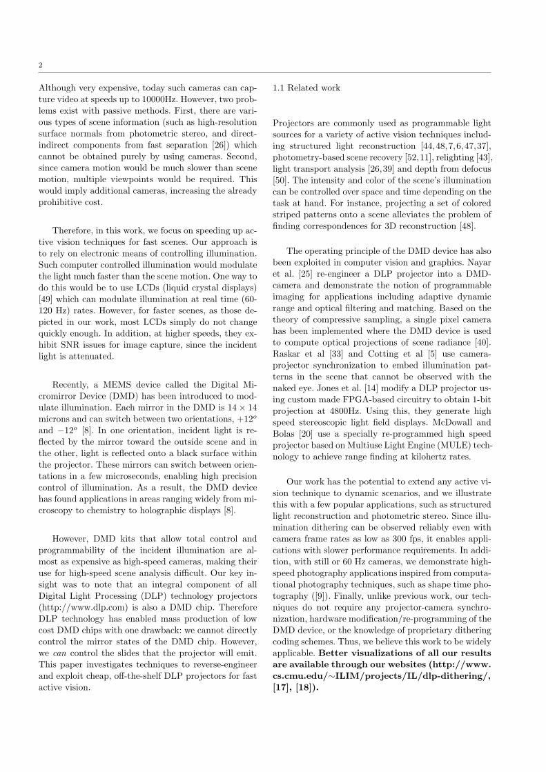
Fig. 1 Reverse engineering a DLP Projector: (a) A DLP projector converts the input intensity received into a stream of light pulsesthat is then projected onto a screen. A high speed camera viewing the screen aggregates the brightness over the duration of itsintegration time. (b) An image composed of 5× 5 pixel blocks each with a different intensity from 0 to 255 is input to the projector.(c) The camera records the projector output at 10 kHz. In (d) we show gray-valued intensities measured over time by the high speedcamera for 4 example intensities input to the projector. Notice the significant variations in the plots. In (e), the temporal ditheringfor all 256 projector input intensities is collated into an image. This temporal dithering is repeatable and can be used to encodeillumination in a novel way, enabling fast active vision.
2 Temporal Dithering in a DLP projector
In order to project a desired intensity value, the DLP
projector emits a series of light pulses of different time
intervals [8]. A sensor aggregates the pulses of light
over the duration of its integration time (say, 1/30sin a video camera) to capture the final gray-valuedbrightness. This Pulse-Width modulation (PWM) by
the projector is unique for every input intensity and
can be termed as “temporal dithering” of the illumi-
nation. As we shall show, this dithering allows us to
encode scene illumination in novel ways to achieve sig-
nificant speedup in the performance of virtually any
active vision technique.
But how do we capture this high speed dithering?
The exposure time (1/30s) of a video camera is too long
to observe the temporal illumination dithering clearly.
One possibility is to precisely synchronize the camerawith a DLP projector and to expose the camera onlyfor the duration of a single projected light pulse (for a
few microseconds as in [5]). This would restrict us to
applications with 30-60Hz performance requirements.
In contrast, our work focuses on exploiting the tem-
poral dithering for fast active vision. For this, we use a
novel combination of a high speed camera and an off-
the-shelf DLP projector. Figure 1 illustrates the dither-
ing of an 8-bit InFocus IN38 DLP projector as observed
by a Photron PCI-1024 high speed camera. An image
composed of 5 × 5 pixel blocks each with a differentintensity value from 0 to 255 is input to the projector.
Each intensity at a pixel C in this image is projected
onto a flat screen using a unique temporal dithering
DC(t), over discrete time frames t. The high speed cam-
era observes the projected images at 10 kHz. Notice the
significant variation in the images recorded. The plot in
Figure 1(d) shows the temporal codes emitted by theprojector for 4 input brightnesses (165, 187, 215, 255),as measured over 100 camera frames. The temporal
ditherings corresponding to all the 256 input intensities
are collated into a photograph for better visualization
of this principle.
Temporal dithering occurring in a commercial pro-
jector is not the only effect measured by the profiles in
Figure 1. The projector has a bulb that is never really

4
Fig. 2 Illumination and acquisition setup for structured light
based 3D reconstruction: (a) The Photron high speed camera isplaced vertically above the Infocus DLP projector in our acqui-
sition setup. A vertical plane is placed at known distance be-hind the scene to enable finding correspondences. (b) The scene(statue) is illuminated using only a single pattern, as shown onthe right. This pattern is static when viewed directly by unaidedeyes. At high-frame rate, however, it is decomposed into a high-frequency patterns by the DLP projector.
“turned off” even when projecting black pixels. This is
why all the projectors have a non-zero minima, and can
be easily corrected by subtracting the ambient imagedue to a black slide. In addition, we use no synchro-nization, and therefore the different profiles are mea-
sured across different positions of the color-wheel (since
measuring 100 frames at 10kHz requires a 1
100
thsecond,
which is approximately a single color-wheel cycle). This
explains the intensity shift in the profiles, which can be
addressed by using a projector with the color-wheel re-
moved (as in Section 6, [19], [4]). If those two calibration
steps are taken, the profiles in the figure would closelyresemble the binary “step function” codes we wouldexpect ([8]). Any remaining differences are attributable
to the spatial dithering imposed by the manufacturer
(discussed in Section 7). These differences do not affect
the use of structured light approaches, since the confu-
sion matrices (depicting the closeness of the profiles toeach other) are consistently diagonal, as shown in Fig.3 and Fig. 17 and discussed in Section 7, where we alsodemonstrate the repeatability of these patterns.
The projected temporal dithering codes vary at about
10000Hz, which is faster than most dynamic scenes and,in our experience, is detectable by high-speed cameras
with a frame-rate of 250fps or more. Consider a dy-
namic scene and a high-speed camera whose frame-rate
is selected such that, over a short interval of measured
frames, the scene appears essentially static. If the cam-
era frame rate is above 250fps, then the illumination in
these frames will vary, even though the scene appears
to have no motion.
This is exactly the assumption made by many active
vision algorithms, and therefore, if we pick an appropri-
ate pattern to project, we can extend these methods to
dynamic scenes. In the next sections, we will exploit this
aspect of DLP illumination to enable dynamic scene re-
covery and capture using well-known techniques such
as structured light reconstruction, photometric stereo,
illumination demultiplexing and strobe-light photogra-
phy. In all our experiments (Sections 3 through 6), each
projector emits a single slide and the selection of the
slide pattern is done heuristically; for example, we se-
lect a random trio set of intensities for the three pro-
jectors in photometric stereo. Designing better patterns
requires understanding different characteristics of the
DLP illumination codes, and in Section 7 we do so for
a particular projector/high-speed camera case. In that
discussion, we also present a brute-force search method
for selecting the pattern of the slide that the projector
will display. We conclude with Section 8 that includesa description of the limitations, trade-offs and other is-sues relating to this work.
3 3D Shape Acquisition
Structured light-based triangulation has commonly been
used for 3D reconstruction [44,31,1]. A known set of
patterns that change their intensity spatially and/or
temporally is projected onto a scene and the reflected
images are used to find the corresponding pixels be-
tween the projector and the camera [35]. The corre-
sponding pixels are then triangulated spatially to ob-
tain 3D structure. It is assumed that the scene motionis negligible or sufficiently small [42] while the patternsare projected. Since projectors have been operated at30− 60 Hz, most implementations achieve slower than
real-time performances. Using these same algorithmswith the fast illumination dithering in a DLP projectorshould enable high speed reconstruction.
Our goal is to obtain correspondences from cam-
era pixels to projector pixels at high speeds. For con-venience, the camera and the projector are placed ina fronto-parallel configuration with a vertical baseline
(see Figure 2). The high speed camera is operated at
3kHz and the projector is reverse engineered at this
speed as described in Section 2. We assume that the
camera and the projector are geometrically calibrated
in advance. In our experiments, the intrinsic parameters
of a camera are estimated by using a planar calibration
pattern [51], and the other parameters are determined
using the homographies between the image planes of
camera and projector [34].
3.1 Illumination Pattern
The differences the among existing techniques of struc-
tured light-based triangulation lie in the illumination
5
1.0
0.0
(a) dot-product of intensity (b) worst match of gradient (c) dot-product of gradient
(d) histograms of function values
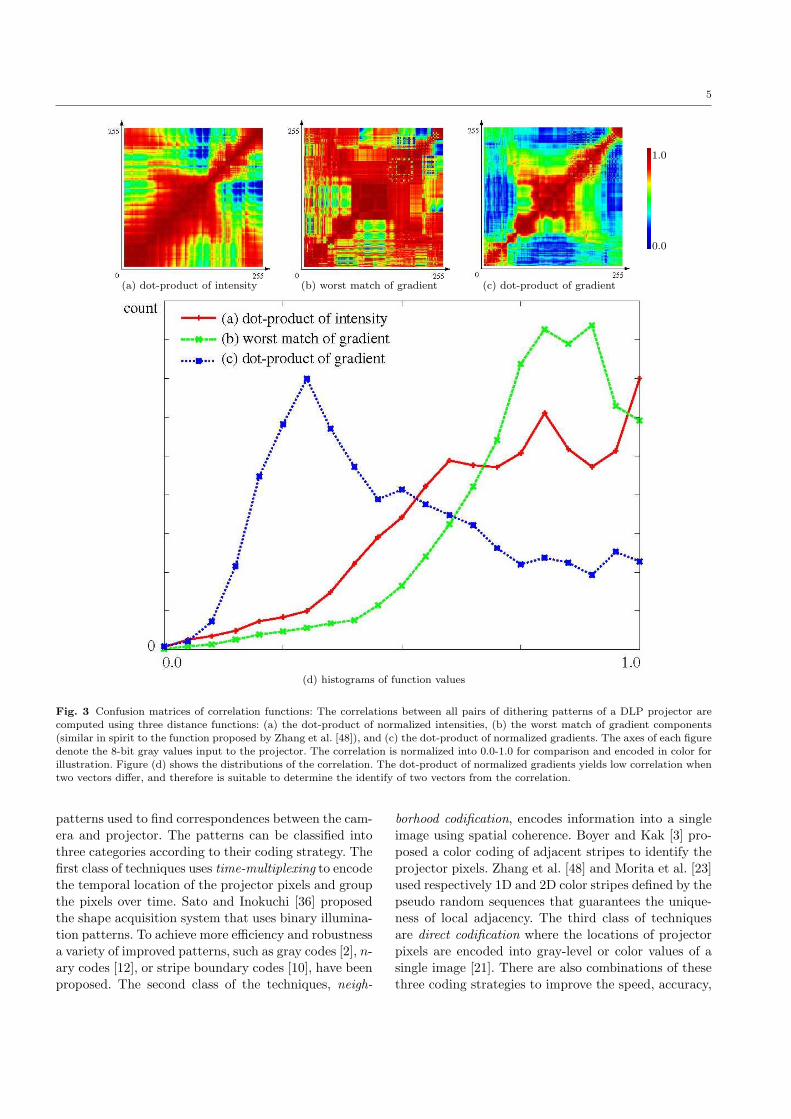
Fig. 3 Confusion matrices of correlation functions: The correlations between all pairs of dithering patterns of a DLP projector arecomputed using three distance functions: (a) the dot-product of normalized intensities, (b) the worst match of gradient components(similar in spirit to the function proposed by Zhang et al. [48]), and (c) the dot-product of normalized gradients. The axes of each figuredenote the 8-bit gray values input to the projector. The correlation is normalized into 0.0-1.0 for comparison and encoded in color forillustration. Figure (d) shows the distributions of the correlation. The dot-product of normalized gradients yields low correlation when
two vectors differ, and therefore is suitable to determine the identify of two vectors from the correlation.
patterns used to find correspondences between the cam-
era and projector. The patterns can be classified intothree categories according to their coding strategy. Thefirst class of techniques uses time-multiplexing to encode
the temporal location of the projector pixels and groupthe pixels over time. Sato and Inokuchi [36] proposedthe shape acquisition system that uses binary illumina-tion patterns. To achieve more efficiency and robustness
a variety of improved patterns, such as gray codes [2], n-ary codes [12], or stripe boundary codes [10], have been
proposed. The second class of the techniques, neigh-
borhood codification, encodes information into a single
image using spatial coherence. Boyer and Kak [3] pro-
posed a color coding of adjacent stripes to identify the
projector pixels. Zhang et al. [48] and Morita et al. [23]
used respectively 1D and 2D color stripes defined by the
pseudo random sequences that guarantees the unique-
ness of local adjacency. The third class of techniques
are direct codification where the locations of projector
pixels are encoded into gray-level or color values of a
single image [21]. There are also combinations of these
three coding strategies to improve the speed, accuracy,

6
(a) Illumination pattern
(b) Temporal dithering (c) Confusion matrix
Fig. 4 The illumination pattern for 3D shape acquisition. (a)We generated a color stripe pattern composed of size 512 distinctcolors (w = 512). (b) The temporal dithering patterns of a DLP
projector for the colors used in the stripes. (c) The confusionmatrix of the dithering patterns, showing high correlation only
along the diagonal.
and robustness of 3D reconstruction. Refer to [35] for
a comprehensive survey.
In theory, any of these illumination patterns can beused for high-speed shape acquisition. The existing al-
gorithms of 3D shape reconstruction can be applied di-rectly to high-speed systems. In practice, however, gen-erating arbitrary illumination patterns requires a DMDkit, which is prohibitively expensive. One possible way
to overcome the limitation is to modify the projector
hardware to generate arbitrary binary patterns at high
speed [20,14]. Instead, we propose to use the dithering
patterns from DLP projectors.
The dithering function transforms the 24-bit RGBcolor input, sent to the projector, into a binary se-
quence. It is then converted into a sequence of gray-
valued intensities due to the mismatch of the synchro-
nization between camera and projector, and the inten-
Fig. 5 Results of 3D reconstruction using the DLP projector fora static venus bust: (a) Three frames captured by the high speed
camera illustrate the fast modulation of illumination incident onthe scene. 20 continuous frames are used to match the intensityvariation observed on the scene point against the normalized in-tensity variation observed on the vertical plane behind the object.(b) The best match finds correspondences between projector andcamera pixels. The error map is shown in (c). The (d) dispar-ity and (e) recovered shape of the object is shown from different
viewpoints.
sity leakage between adjacent frames. Let I(v, t) be the
intensity of a scene point on a white plane, illuminated
by a projector with the input intensity v, and observed
by a high-speed camera at time frame t. The inten-
sity vector I(v) = (I(v, t0), . . . I(v, t1)) acquired for aprojector-frame cycle t = t0, . . . , t1 characterizes the
image intensity at a scene point illuminated by a projec-
tor pixel with intensity v. Conversely, when we obtain
an intensity vector at another scene point, the corre-
sponding projector input v′ can be identified by finding
the maximal correlation between I(v) and I(v′) for all
v.
Ideally, the correlation between two vectors v and
v′ would be maximum when v = v′, and would become
as low as possible when v 6= v′. It is also desirable that
a large number of pairs (v, v′) yields low correlations in
order that each projector intensity in a stripe pattern
be robustly distinguished. Since the optimal correla-
tion function depends not only the dithering function of
the projector, but also the performance of a high-speed
camera, we have investigated three different functions:

7
(a) Normalized dot-product of intensities:
Da(v1, v2) =I(v1) · I(v2)
‖I(v1)‖‖I(v2)‖(1)
where v1 and v2 are intensities input to a projector.(b) Worst match of image gradients :
Db(v1, v2) = maxt0,...,t1−1
−G(v, t) (2)
where G(v, t) = I(v, t+ 1)− I(v, t).
(c) Normalized dot-product of gradients:
Dc(v1, v2) =G(v1) ·G(v2)
‖G(v1)‖‖G(v2)‖(3)
where G(v) = (G(v, t0), . . . G(v, t1 − 1))
The normalized dot-product of intensities is one ofthe simplest and commonly-used correlations of two
vectors. It, however, has high correlation values for a
large number of pairs as illustrated in Figure 3 (a),
which implies potential ambiguity in correspondence at
these pair of intensities. The worst match of gradient
components is similar in spirit to the correlation func-
tion used by Zhang et al. [48] It penalizes the disagree-
ment of sign in gradient components, and takes a large
value only when all components have consistent signs.
However, as shown in Figure 3 (b), this function also has
considerable ambiguity because the camera and projec-
tors are not perfectly synchronized and the high-speed
camera suffers from the noise due to the temporal blur-
ring between frames. The effect of temporal blurringcan be seen in Figure 1 (d). The observed image inten-sities have continuous distribution whereas the output
of a DLP projector is originally binary. Accordingly,
we decided to use the normalized correlation of gradi-
ents to compute the correlation between the observed
intensity vectors (Figure 3 (c)). Figure 3 (d) shows the
distributions of the three correlations. The dot-product
of normalized gradients yields low correlation when two
vectors differ, and therefore is suitable to determine the
identify of two vectors from the correlation.
Note that we computed the correlation only between
8-bit gray values, while ideally all pairs of 24-bit RGB
colors should be compared. We simplified the experi-
ment based on the following consideration: The tempo-
ral dithering pattern in each color channel looks simi-
lar to that of gray values. The global optimality is not
required either; In fact, we used the normalized corre-
lation of intensity in our earlier work [24].
The illumination pattern is then created by choos-
ing the projector intensities that can be robustly distin-
guished by the correlation functionDG. Since we do not
have the confusion matrix of full 24-bit RGB colors, the
stripe pattern is generated by randomly choosing dis-
tinct RGB colors such that the correlation of any pair
of the colors is less than a certain small number. Fig-
ure 4 shows the illumination pattern we used in our
experiments. The number of the stripes in the pattern
is w = 1024, but is reduced to 256 in the figure for vi-
sualization purpose. Each RGB color v = (r, g, b) of thestripe is generated such that r, g, b ∈ [100, 255] because
dark illumination leads to low signal-to-noise ratio of
camera images and causes unreliable decoding.
3.2 Reconstruction Algorithm
Given the high-speed images of an object illuminated
by a DLP projector, the correspondence from camera
pixels to projector pixels can be determined by com-
puting the correlation functions described in Section
3.1. It would seem that simply knowing both the slide
sent to the projector and the ditherings from Figure
1 would be sufficient for finding camera-projector cor-
respondences. However, this method does not result in
correct correspondences since the camera and projector
are not synchronized. Finding the exact phase differ-
ence between the camera and projector would result in
a large search problem, which we wish to avoid. How do
we synchronize the frames from the projector and the
camera? One approach is to include a small, diffuse pla-nar patch in the scene where correspondence betweenthe corners of the patch can be easily established (say,manually). This correspondence allows us to synchro-
nize the measured intensity vector with the temporal
dithering.
3.3 Results
Consider a high speed camera viewing a dynamic scene
that is illuminated by a DLP projector. We use a single
image composed of 1D patterns as the input to the
projector. The correspondences from camera pixels to
the stripe are sought using the epipolar constraints of
the camera and projector.
We performed several experiments with both staticdynamic objects: a static statue, a waving cloth, a grasp-
ing hand, a face, and a hand spinning a pen. A homoge-
neous vertical plane is used as the background behind
the scene. The dithering DI(t) can be captured from
the pixels on this plane and simultaneously with the
object. Hence, in this setting, we simply correlate the
normalized brightness vector I(t) of a point on the ob-
ject with the dithering vector DI(t) at every pixel C on
the background plane and no additional synchroniza-
tion is needed.
Here, twenty frames were used to obtain correspon-
dences, taking 20/3000 = 1/150s . In general, the num-
8
cloth
hand
face
pen
-spinning
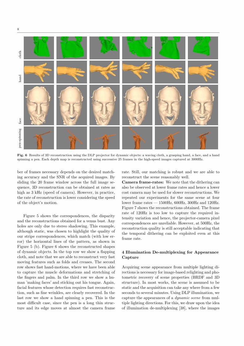
Fig. 6 Results of 3D reconstruction using the DLP projector for dynamic objects: a waving cloth, a grasping hand, a face, and a hand
spinning a pen. Each depth map is reconstructed using successive 25 frames in the high-speed images captured at 3000Hz.
ber of frames necessary depends on the desired match-
ing accuracy and the SNR of the acquired images. By
sliding the 20 frame window across the full image se-
quence, 3D reconstruction can be obtained at rates as
high as 3 kHz (speed of camera). However, in practice,
the rate of reconstruction is lower considering the speed
of the object’s motion.
Figure 5 shows the correspondences, the disparityand the reconstructions obtained for a venus bust. Any
holes are only due to stereo shadowing. This example,
although static, was chosen to highlight the quality of
our stripe correspondences, which match (with low er-
ror) the horizontal lines of the pattern, as shown in
Figure 5 (b). Figure 6 shows the reconstructed shapes
of dynamic objects. In the top row we show a flappingcloth, and note that we are able to reconstruct very fastmoving features such as folds and creases. The second
row shows fast hand-motions, where we have been able
to capture the muscle deformations and stretching of
the fingers and palm. In the third row we show a hu-
man ’making faces’ and sticking out his tongue. Again,
facial features whose detection requires fast reconstruc-tion, such as fine wrinkles, are clearly recovered. In thelast row we show a hand spinning a pen. This is the
most difficult case, since the pen is a long thin struc-
ture and its edge moves at almost the camera frame
rate. Still, our matching is robust and we are able to
reconstruct the scene reasonably well.
Camera frame-rates: We note that the dithering canalso be observed at lower frame rates and hence a lower
cost camera may be used for slower reconstructions. Werepeated our experiments for the same scene at fourlower frame rates — 1500Hz, 600Hz, 300Hz and 120Hz.Figure 7 shows the reconstructions obtained. The frame
rate of 120Hz is too low to capture the required in-
tensity variation and hence, the projector-camera pixel
correspondences are unreliable. However, at 500Hz, the
reconstruction quality is still acceptable indicating thatthe temporal dithering can be exploited even at thisframe rate.
4 Illumination De-multiplexing for Appearance
Capture
Acquiring scene appearance from multiple lighting di-
rections is necessary for image-based relighting and pho-
tometric recovery of scene properties (BRDF and 3D
structure). In most works, the scene is assumed to be
static and the acquisition can take any where from a fewseconds to several minutes. Using DLP illumination, wecapture the appearances of a dynamic scene from mul-
tiple lighting directions. For this, we draw upon the idea
of illumination de-multiplexing [38], where the images

9
120Hz 500Hz 1000Hz 3000Hz
Fig. 7 Reconstructions obtained using videos captured
at reduced frame rates. Even at 500Hz, the quality of thereconstruction obtained remains acceptable indicating that tem-poral dithering can be exploited at this frame rate.
of the scene are simultaneously captured from multiple
source directions and de-multiplexed in software to ob-
tain the desired images under each lighting direction.
This technique increases the signal-to-noise of the cap-tured images while keeping the number of captured im-ages unchanged.
The difference between Schechner et al. [38] and our
technique is in the coding: they use binary Hadamard
codes, whereas we rely on the temporal dithering of
DLP illumination. The acquisition setup consists of three
DLP projectors (Infocus IN38 and LP120, and Sony
XGADataProjector) that simultaneously illuminate thescene from different directions. Since we wish to illumi-nate the scene uniformly, a single constant brightnessimage is input to each of the projectors.
The three projectors differ in their brightness and
contrast ratings and dithering behaviors. The capturedintensity at time instant t is written as a sum of ir-
radiances due to the illuminations from all projectors
(k = 1 . . . 3):
I(t) =
3∑
k=1
Dk(t)Ek(t) (4)
where, Dk(t) is the dithering intensity of the projector
k at time t and Ek(t) is the irradiance due to the scene
as if illuminated only from projector k but with unit
intensity. The intensities Dk(t) can be obtained by ob-serving a calibration object; this could either be a sta-
tionary mirror/lambertian sphere placed in the scene,
or a diffuse lambertian background plane placed such
that the edges of the three projector’s FOV are visible.
The observed irradiances I(t) over time form a linear
system which is solved to obtain the appearances Ek(t)of the scene from each individual lighting direction. In
practice, since the projectors are not synchronized when
they illuminate the scene, the dithering intensities Dk
vary significantly over time, and hence the linear system
is well-conditioned.
Figure 8 shows the results of applying the above ap-
proach to a scene with a falling wiry ball. Notice the
3 shadows of the ball and the mirror sphere that ap-
pear mixed in the multiplexed image I(t). For robust-
ness, we use 10 frames to solve the above linear system.
Notice separation of the shadows in the demultiplexed
images. As before, the effective rate of demultiplexing
depends on the SNR in the high speed camera. We have
thus far ignored color information, however, when thethree DLP projectors emit intensities in different spec-tral bands, the de-multiplexing algorithm can be used
to colorize the acquired high speed gray-scale video.
4.1 Colorizing High-speed Video by Demultiplexing
In the previous section we showed how choosing the
right projector intensities can enable fast illumination
demultiplexing for dynamic scenes. In this section, we
show one application of demultiplexing to colorize a
high speed video. In Figure 9 we show our setup in (a),
where three DLP projectors are used to illuminate a
scene and their centers of projection are kept close to
minimize scene shadows. Instead of a reflective sphere,
we use a diffuse background to estimate the intensities,
as explained in the next section. Each projector is fit-
ted with a color filter, and the demultiplexed images
obtained are the response of the scene to red, green
and blue illumination. We can, therefore, create a color
image of the scene as shown in the figure. Since we re-
quire 30 images for the demultiplexing, and the frame
rate of the camera was 3000hz, the effective frame rate
of the color video is 100hz.

10
Fig. 8 Demultiplexing illumination from three projectors to create appearances under each lighting direction: The scene consists ofa wiry polyhedral ball falling vertically. Notice the mixing of the shadows in the multiplexed images in (a). A mirror sphere is placedin the scene to measure the dithering intensities Dk from the three projectors. (b) The results of demultiplexing for two frames inthe video sequence. A total of 10 frames are used to demultiplex. Some ghosting artifacts are due to the noisy estimation of source
intensities Dk. The variation in the contrast and brightness of the three demultiplexed images are due to the quality of the threeprojectors. Projector 2 (InFocus IN38) is the most recent one and has the highest quality.
Our Photron PCI-1024 camera produces black andwhite images, while a similar color high speed would
cost almost double this. Therefore we believe our method
is extremely practical and useful. One issue of our ap-
proach is that commercial DLP cameras have a color
wheel inside them, that have red, green, blue and white
filters turning at about 120hz. This violates our as-
sumption that each projector corresponds to only onecomponent of the spectrum. Therefore, we have removedthe color-wheel in the DLP projectors before perform-
ing the experiment. In the last row of Figure 9 we show
one colored frame, but please view the video on the
website ([18]) for a full length clip.
5 Illumination Multiplexing for Photometric
Stereo
Photometric stereo is a widely used method to recover
the surface normals and albedos of objects that are pho-
tographed under different lighting directions. There are
many variants of this approach and we chose the classic
algorithm by Woodham [45] for its simplicity. In that
work, the appearance of the scene under three indepen-
dent distant illumination directions is used to obtain
the surface normal of the scene point. We will extend
this approach for fast moving scenes that are simulta-
neously illuminated from different directions.
The scene in our experiments consists of a mirrorsphere, a white diffuse background plane and a flutter-
ing white cloth flag (Figure 10). These are illuminated
by three DLP projectors simultaneously from different
directions and viewed by a high speed camera recording
images at 3 kHz. Since each projector must uniformly il-
luminate the scene, we provide a single constant bright-ness image as input to each projector (with differentbrightness values). The projectors are de-synchronized
and hence, the “multiplexed illumination” results in
significant variation in the observed intensities. In ad-

11
Fig. 9 Colorizing a high-speed video: Here we apply the demultiplexing technique, where red, green and blue color filters havebeen applied to the projectors. The projector color-wheels were removed before this experiment was run. The input images show thewhite cardboard at the right of the scene, on which the edges of the three projected slides are visible. These three edges are clearlydemarcated in the demultiplexed images. The intensities of these demultiplexed images are the responses to the red, green and bluecomponents of the scene albedos (up to a scaling factor). These are concatenated to produce a color high-speed video. Note that whileoff-the-shelf DLP projectors are available on the order of 100s of dollars, a color high speed camera would price an order of magnitudehigher.
dition, the projectors and camera are far enough away
from the scene to assume orthographic viewing and dis-
tant lighting.
Each projector has a different field-of-view (FOV)
and therefore (in Figure 10) different parts of the back-
ground plane are illuminated by different projectors.
This allows the edges of each projector FOV to be per-
ceived, as can be seen in the figure. The patches around
these edges are illuminated by different pairs from the
three individual projectors. We use the normalized in-
tensities of these patches as estimations of combinations
of projector intensities and demultiplex the scene. We
then apply classical lambertian photometric stereo to
the demultiplexed video to obtain the surface normal,
using a mirror sphere that provides the projector di-
rections. A window of length 10 frames achieved robust
results. A sliding window of 10 frames can be used to
generate the normals up to a rate of 3 kHz. As before,
the speed of the object determines the effective perfor-
mance rate. Figure 10 shows the reconstructed shapefrom the surface normals. Note the creases and folds inthe flag that are faithfully reproduced.
6 Flutter Flash: Motion-blur under DLPIllumination
Motion-blur occurs when the scene moves more than
a pixel within the integration time of a camera. The
blur is computed as the convolution of the scene mo-
tion with a box filter of width equal to the camera in-
tegration time. Thus, images captured of fast moving
objects cause a smear across the pixels losing signifi-
cant high frequencies. Deblurring images is a challeng-
ing task that many works have addressed with limited
success. A recent approach by Raskar et al. [32] uses
an electronically controlled shutter in front of the cam-
era to modulate the incoming irradiance at speeds far
greater than the motion of the object. In other words,
the box filter is replaced by a series of short pulses of
different widths. The new convolution between the ob-
ject motion and the series of short pulses results in
images that preserve more high frequencies as com-
pared to the box filter. This “Flutter Shutter” approach
helps in making the problem better conditioned. Our
approach is similar in spirit to [32] with one difference:
the fast shutter is simulated by the temporal dithering
of the DLP illumination. Note that the DLP illumi-
nation dithering is significantly faster than mechanical
shutters 1.
In Figure 11(a)-(c), we show images taken under
DLP, skylight and fluorescent illumination. The object
is a cardboard sheet translating from left to right with
the PSF approximated by a small white dot placed
on the sheet. We use this as a good starting point for
blind deconvolution methods. For skylight and fluores-cent light, we also tried the ’box’ PSF which assumes
1 Faster shutters can be realized by electronically triggering
the camera.

12
Fig. 10 Photometric stereo: The scene consists of a fast moving fluttering cloth flag, a background diffuse plane and a mirror sphere.Three DLP projectors simultaneously illuminate the scene and the camera operates at 3000Hz. The projectors and camera are far
enough away from the scene to assume orthographic viewing and distant lighting. The patches on the calibration plane correspond tocombinations of different pairs of the three projectors. We use these to demultiplex the scene and calculate the surface normals from
the demultiplexed frames by classical photometric stereo. A window length of 10 frames achieved robust results.
Fig. 11 DLP photographs contain higher frequencies compared to other types of illumination: In (a) and (b) we show
deconvolution results with skylight and fluorescent illumination. The blind deconvolution algorithm was given the intensity profile ofa white dot as a starting point. The result for deblurring the same motion under DLP illumination (c) can be read easily. Analysis offrequencies in the recovered PSF shows DLP illumination preserves high frequency information.
constant incident illumination during exposure. Note
that the best deconvolution occurs with the DLP pho-
tograph. In Figure 11(d) we show the frequencies of the
PSFs. Note that the highest frequencies are due to theDLP illumination. Although previous work has eitherused camera apertures to create similar images ([32])or shown some deblurring results ([24]), we are the first
to analyze and compare the frequencies of DLP illumi-
nation to other types of lighting.
Deblurring images using flutter-flash (or, as in [32],
flutter-shutter) makes some assumptions about the scene;
for example, we require uniform motion of a rigid body.
For scenes with articulated and deformable objects, a
global flutter does not help to estimate the blurring
function. This is because the blur kernel is local and
can be different at each pixel, making the deblurring
problem hard. Instead of tackling this tough problem,
in this section, we take a alternative approach. We will
demonstrate how to present the high-frequency motion
information available in the DLP photographs, without
deblurring them. This approach is inspired from compu-
tational photography techniques that complement de-
blurring methods.
6.1 The DMD-Colorwheel Effect
Projecting color images involves synchronized control
between the DMD chip, which has a frequency of a
106Hz, and the color wheel, which rotates at 120Hz and

13
is divided into red, green and blue filters. This ‘rainbow
effect’ is well-known to display researchers who wish to
remove or reduce it ([29],[15],[30],[41], [13], [28], [22]).
Many researchers even remove the color wheel to in-
crease the projector contrast in their experiments ([19],
[4]). Instead of treating this effect as a problem that
must be compensated for, the DLP illumination can
be exploited to photograph dynamic scenes. Therefore
DLP illumination can produce strobing effects for bothreal-time and high-speed scenes, and we term this the
DMD-Colorwheel effect.
This strobing effect is special for two reasons. First,
at high-speeds (the DMD part of the effect), the dither-
ing is due to binary switching of a MEMSmirror. There-
fore, the illumination changes sharply, almost as a delta
or step function. This is in contrast to the closest com-
petitor in illumination devices, which are high-speed
LEDs. These solid state devices have a ‘ramp-up’ time,
and would cause blurring in strobe-photography of the
very fast events that we capture, such as an air-balloon
bursting or slingshots. In addition these devices are
more expensive that off-the-shelf DLP projectors. Sec-
ondly, at real-time speeds (the colorwheel part of the ef-
fect), the strobe effect creates multiple colored copies of
the object. This allows interesting color demultiplexing
effects that can illustrate the motion. These are difficult
to perceive as images, and so we only include them as
videos on our DLP photography website, [17]. Instead,
in this section, we will focus on motion illustrations
that can be displayed as still photographs. We call im-
ages of scenes under DLP illumination taken by still or
low-frame rate cameras, as DLP photographs.
6.2 DLP Photography
The DMD chip has a frequency of a 106Hz, but the
dithering in a commercial projector occurs at around
f = 10000 Hz ([24]). This allow us to capture very
high-frequency events such as the air balloon burstingas showing in Figure 12. Note that most other forms
of illumination would cause blurring in this image. Asan example, we show that under fluorescent lighting,viewed at 1000fps, the balloon is smeared in a singleframe, and this high-speed event is lost. However, when
viewed under DLP illumination, the images at 1000fps
show copies of the edge of the balloon. We used an
Infocus In38 projector projecting a plain gray image
of intensity 192 of 3000 lumens, viewed by a PhotronPCI-1024 high-speed camera. Our setup enables pho-tography of an event occurring at 10 times the frame
rate of the viewing camera. Finally in the figure, we
use three projectors that are unsynchronized creating
a higher strobing frequency and therefore obtaining a
similar photograph at a lower frame rate of 500Hz.
In contrast to the very high-speed events describedabove, the color component of the DMD-colorwheel ef-
fect is clearly visible for scenes with ’real-time’ move-
ments such as fast human motion. In Figure 13 we show
pictures of a tabla (hand drum) being played, as well
as a ballet dancer performing. Note that the copies ap-
pear at different colors, since they are illuminated whenthe color wheel turns the red, green or blue filters. Wealso show an image of a water-balloon bursting. The
specularities of the water droplets are clearly colored
red, green and blue, and these would have been blurred
under fluorescent illumination.
6.3 Summarizing Fast Events
An image summarizing a video sequence can be created
by stitching important frames together, as in shape-
time photography ([9]). However, the object must move
slowly since otherwise motion blur will render the final
result difficult to interpret. DLP photographs already
summarize a short burst of action, since they contain
multiple copies of moving objects. Applying a similar
method as shape-time photography to a collection of
DLP photographs creates a summary image for fast mo-
tion.In Figure 14 we show images created by process-
ing a volume of DLP photographs of a tabla player
and a ballet dancer. We first separate the images ap-
proximately into the strobed and non-strobed part us-
ing a well-known intensity-based segmentation method
([46]). Except for the first image, the rest of the im-
ages are strobed. The top image is created by taking
the intensity maxima of each pixel over all the pho-
tographs, which produces the effect of combining thedifferent copies and gives a summary of the motionsthat occurred. In contrast, the bottom of the figure iscreating by masking the high intensity portions of each
image and pasting them on top of each other. Instead of
blending the outputs, these summaries enforce an order
into the images.
While the previous examples showed images taken
at ’real-time’ rates (such as a human dancing or mov-
ing) with the colorwheel effect, now we look at strob-
ing created by fast moving scenes with the DMD chip.
In Figure 15 we show image summaries of a slingshot
shooting a rock at high speeds. This summaries were
created by applying the method of [9] to high-speed
frames. The first result taken under fluorescent illu-
mination with a 1000Hz camera, clearly shows high-
frequency information. The same experiment taken with
a 250Hz camera shows motion blur. However, replacing

14
Fig. 12 DLP photographs of a bursting balloon: An air balloon bursting can be captured fully using a 10000hz camera. In the
first image we show what happens when the event is captured under fluorescent illumination, with a lesser rate of 3000hz. In one framethe event is lost in motion blur. In the next two images, we show images taken under 3000hz, but this time with DLP illumination.Notice the multiple copies of edge of balloon as it moves. We are able to capture images of this high-speed event, due to the temporal
dithering of the DMD device in the projector. Similarly in the last image, we use three DLP projectors, which are not synchronized.We are able to capture a balloon bursting with a 500hz camera, which is much slower than the speed of this fast event.
Fig. 13 Selected DLP photographs: We photographed two artists, a ballet dancer and a tabla (hand drum) player, under DLP
illumination. Both activities are ’real time’ and the color wheel effect dominates the images. The camera exposure was 1 second. Wealso show a balloon bursting, where the specularities of the water droplets are clearly colored red, green and blue. These would havebeen blurred under fluorescent illumination.
the fluorescent light with a DLP projector, creates an
image on the right with the same high-frequency infor-
mation obtained by a 1000Hz, but done with a 250Hz
camera. Therefore, fast strobing of a DLP projector can
enhance the effective frame rate of a camera by allow-
ing to capture scenes moving faster than its frame rate.
In the second row, we show a more interesting scene in-
volving a collision of a slingshot rock and a stationary
plastic pear. By applying [9]’s method to different sub-
sets of the video, we can summarize different aspects ofthe event.
7 Temporal Dithering Characteristics: A CaseStudy
In the previous sections, we have shown how the tempo-
ral dithering of a DLP projector can be used to extend
any active vision technique to dynamic scenes. In all
our experiments, we used patterns that were selected
heuristically to provide best results. Providing a moretheoretical analysis is difficult, since, in our experience,the dithering codes drastically differ with small changes
in projector controls (such as contrast or brightness)
and environment (such as temperature) as well as be-

15
Fig. 14 Colorwheel motion summaries: By combining DLP photographs in different ways we can summarize events. For boththe tabla player, (a), and the ballet dancer, (b), we show summaries created by taking pixel maxima as well as by masking andsuperimposing the images. In the maxima case, no image ordering exists and all edges are blended. In the masking case, image order
matters and edges exist between different stages of the action.
tween projectors of different manufacture. Still, we be-
lieve it would be useful to perform a broad empirical
evaluation of a particular case, involving the InFocus
IN38 DLP projector as observed by a Photron PCI-
1024 high-speed camera. In this section, we perform
such experiments to investigate two important tempo-
ral dithering characteristics.
First, the dithering codes must be reliable and should
not change arbitrarily. This would enable robust be-
havior for a vision system calibrated with a particular
projector. Secondly, there must not be a large extent
of overlap or redundancy in the dithering codes since
this will constraint the possible set of illumination pat-terns. Finally, we will discuss a brute-force method tofind incident illumination patterns from the measured
profiles. We will begin here by describing experiments
investigating the reliability and redundancy of tempo-
ral dithering codes:
Reliability: The temporal dithering is stable andrepeatable but varies for each projector-camera system.
Figure 16 investigates the consistency of the pattern
for pixel intensity 250 at 10000Hz. We can see that the
code varies periodically and repeats itself. This tempo-
ral dithering is the code that the projector uses to rep-
resent the intensity 250. We can also observe that the
standard deviation of the repeated values is not high
(≤ 1
5of the intensity). This means that the temporal
dither that we measure is reliable, in the sense thatit preserves maxima and minima (peaks and troughs)
from cycle to cycle. We have found that this holds for allthe 255 pixel values for frame-rates of 10000Hz, 3000Hzand a 500Hz.
In addition to the repeatability of the dithering, we
have also found dynamic range issues in this particularprojector-camera pair. The image shown in Figure 1 isdark for the input brightness range of 0 to 90. Despite
the claim from manufacturers that the projector dis-
plays 8-bits of information, only about 160 patterns are
usable for our experiments. To compensate for this, the
projector performs spatial dithering in addition to tem-
poral dithering in a few pixel blocks. This is an almostrandom effect that is not possible to reverse engineerwithout proprietary information from the manufactur-
ers. We smooth out this effect by simply averaging over
a small neighborhood for our processing.

16
Fig. 15 DMD motion summaries: Here we show experiments with a slingshot, which moves fast enough that the strobing effectsare due to the DMD dithering and not the colorwheel. In the top row we demonstrate how DLP illumination allows the image capture
of dynamic scenes with a low frame rate camera. In the bottom row we show how applying the method of [9], allows the summary ofdifferent aspects of a fast moving event, again with a low-frame rate camera.
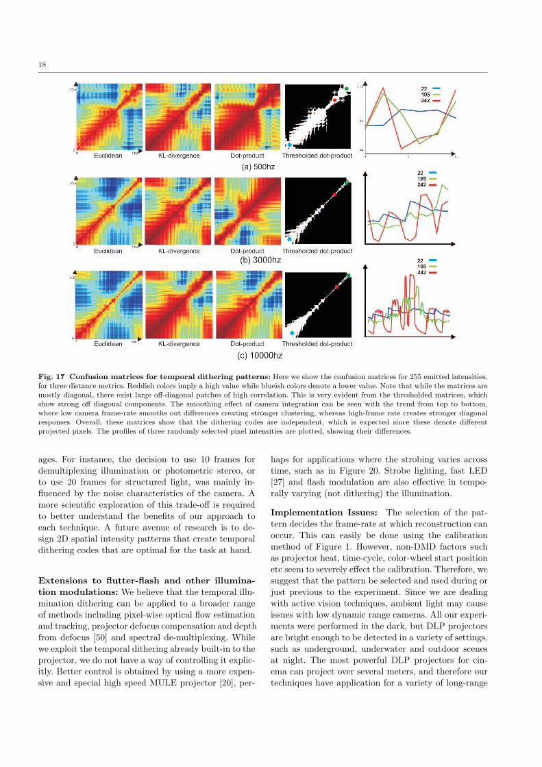
Redundancy: In Figure 17, we show confusion ma-trices for all 256 patterns for three frame rates and for
three metrics, euclidean, dot-product and KL-divergence.From the strong diagonal in these matrices, it is clearthat each pixel has a unique encoding, and the profilesfor three randomly selected intensities in the fifth col-
umn demonstrate this. The independence of these pro-
files is expected, since otherwise the projector would
not be able to produce different emitted intensities.
However, if we observe the fourth column in the figure,where one of the confusion matrices is thresholded, weobserve that while most of the energy in the matrices
is along the diagonal, there are many off diagonal ele-
ments, implying that clusters exist in the pattern. An
intuitive explanation of this is that since the dithering
code is integrated to provide the final pixel intensity,
only a few mirror states need to be altered to move fromone pixel intensity to one that is only slightly greateror lesser.
The reliability of the temporal codes opens up their
use in active vision applications. However, the implica-tions of their redundancy require careful selection of thecodes and the illumination pattern that they imply. Inthis paper, we have empirically selected patterns, and
we leave a more principled analysis for future work.
However, we can suggest a simple brute-force approach
for pattern design.
Designing an illumination pattern through
brute-force search: Consider the toy problem in Fig
18, where we wish to project a 2x2 alternating checker-
board pattern onto the scene. Since the diagonal inten-
sities of the checkerboard must be consistent, we must
choose two values to make up the 2x2 checker board. At
the right of the figure, we show the profiles for the in-tensities 200 and 230 at 10kHz. In the 100 frame cycle,there are only two frames where the projected inten-
sities at different enough to appear as a checkerboard
pattern. If we pick these, we obtain the desired checker-
board pattern, but at a reduced 100Hz. The bottom row
shows the projected intensities on a scene for these two
frames, showing the checkerboard pattern.
Therefore to obtain a desired pattern, we must first,
pick the static pattern to project (in the previous case
it was alternating squares of value 200 and 230) and
second, pick the frames to consider (such as frames
1 and 100 in the figure). Let the desired pattern be
APQR, which is essentially an R length sequence of
PxQ frames. In the previous example, this would be
A222 where the 2x2 pattern at R = 1 is a checkerboard
and the 2x2 pattern at R = 2 is the inverse checker-
board. Now consider the dithering codes, as arranged
in Figure 1(e). That image can be denoted as an ar-ray Tij where i is the pattern index (0-255) and j is
the frame number in the periodic cycle (for 10kHz in
the figure, j varies from 1 to 100). We wish to extract
APQR from Tij .
First we must compute the static pattern to project.Since there are PxQ slots, there are 255PQ choices. If we
can reduce these choices, by enforcing a spatial relation-
ship between the patterns (such as alternate squares
17
Fig. 16 How reliable is the dithering code?: In the first column we show the temporal dithering observed at a pixel of intensity250, captured at 10000Hz. Note that after a few frames the illumination code starts to repeat. We accumulated ten such patternsand superimposed them on each other, shown in the center column. These qualitatively show that the dithering code is consistent. A
quantitative measure showing standard deviation is shown in the third column, and similar results hold for other pixel intensities atdifferent frame-rates.
must be identical), we have a reduced space. For thecheckerboard example, this is 2552. Every candidate in
such a reduced exponential space creates a pattern ofsize PxQxN , where N is the periodicity, and for 10kHz
is N = 100.
From each candidate pattern of size PxQxN , we
must specify the R ≤ N frames from these such that
the resulting, smaller sub-set best matches APQR. Since
no two frames can share the same N , this takes (usingcombination notation) nCr steps, if order in A is unim-
portant. This scenario is true for many applicationssuch as photometric stereo or illumination multiplex-ing. If the order in A is important, then each selection
of r reduces the space of possible further frames. This
can be denoted by a summation of permutations givenby Σi ni
Cr starting with n1 = n. A brute force method
would be to calculate the SSD distance between APQR
and these candidates, and select the candidate with thesmallest error.
Detecting the illumination pattern: Consider
an active vision system for a dynamic scene where the
fastest object in the scene moves with an image-plane
speed v , the frame rate of the camera is f and n isthe minimum number of images required to extract
some scene property. For example in classical lamber-
tian photometric stereo, we require three images under
non-collinear distant lighting and n = 3. One way to
extend such techniques to dynamic scenes is to rapidly
vary the lighting such that the apparent object motion
in the time interval nfis zero. Since we would like the
object to appear to be static, we wish to minimize theerror e given by the object motion in the image plane,
e = v.(
nf
)
. To get effective performance we would ide-
ally like e to be zero or at least sub-pixel. Since we can-
not control the object motion v and, usually, the frame
rate f of the camera is fixed, we must vary n. However,
n depends on the requirement of the algorithm.
For example, in reconstruction algorithms, n must
be large enough to enable correspondence matching.
There exists a trade-off between the number of frames
needed for robust matching (larger n) and the abilityto reconstruct fast objects (smaller n). A simple sim-
ulation using the codes taken at 10000Hz is shown in
Figure 19, where the confusion matrices become less di-
agonal as the number of frames becomes low. One final
issue is the nCr selection step in the pattern design.
As shown in Figure 18, a 10000Hz camera reduces to a
100Hz system, since a checkered pattern was required.
Therefore the choice of pattern can render most of the
intensities in the dithering codes as ’useless’ and reduces
the effective frame rate of the system by the number
of correct matches found. Such wasted ditherings are
shown by the gaps between the yellow vertical lines in
the graph in Figure 18.
8 Discussion
We have demonstrated that illumination from DLP pro-
jectors shows flickering or dithering due to the effect of
the DMD chip and shown how to exploit this effect to
extend active vision techniques to dynamic scenes. Weconclude here by providing a brief discussion of sometrade-offs and limitations of our technique:
Speed vs. accuracy trade-off: One limitation ofour approach is the requirement of a high speed camera.The acquisition speed of the camera and the effective
speed of performance achieved depend on the task at
hand and the signal-to-noise ratio of the captured im-
18
Fig. 17 Confusion matrices for temporal dithering patterns: Here we show the confusion matrices for 255 emitted intensities,for three distance metrics. Reddish colors imply a high value while blueish colors denote a lower value. Note that while the matrices are
mostly diagonal, there exist large off-diagonal patches of high correlation. This is very evident from the thresholded matrices, whichshow strong off diagonal components. The smoothing effect of camera integration can be seen with the trend from top to bottom,where low camera frame-rate smooths out differences creating stronger clustering, whereas high-frame rate creates stronger diagonalresponses. Overall, these matrices show that the dithering codes are independent, which is expected since these denote differentprojected pixels. The profiles of three randomly selected pixel intensities are plotted, showing their differences.
ages. For instance, the decision to use 10 frames for
demultiplexing illumination or photometric stereo, or
to use 20 frames for structured light, was mainly in-
fluenced by the noise characteristics of the camera. A
more scientific exploration of this trade-off is required
to better understand the benefits of our approach toeach technique. A future avenue of research is to de-sign 2D spatial intensity patterns that create temporal
dithering codes that are optimal for the task at hand.
Extensions to flutter-flash and other illumina-
tion modulations: We believe that the temporal illu-
mination dithering can be applied to a broader range
of methods including pixel-wise optical flow estimation
and tracking, projector defocus compensation and depth
from defocus [50] and spectral de-multiplexing. Whilewe exploit the temporal dithering already built-in to theprojector, we do not have a way of controlling it explic-
itly. Better control is obtained by using a more expen-
sive and special high speed MULE projector [20], per-
haps for applications where the strobing varies across
time, such as in Figure 20. Strobe lighting, fast LED
[27] and flash modulation are also effective in tempo-
rally varying (not dithering) the illumination.
Implementation Issues: The selection of the pat-
tern decides the frame-rate at which reconstruction can
occur. This can easily be done using the calibration
method of Figure 1. However, non-DMD factors such
as projector heat, time-cycle, color-wheel start position
etc seem to severely effect the calibration. Therefore, we
suggest that the pattern be selected and used during or
just previous to the experiment. Since we are dealing
with active vision techniques, ambient light may cause
issues with low dynamic range cameras. All our experi-
ments were performed in the dark, but DLP projectors
are bright enough to be detected in a variety of settings,such as underground, underwater and outdoor scenesat night. The most powerful DLP projectors for cin-
ema can project over several meters, and therefore our
techniques have application for a variety of long-range

19
Fig. 18 Patterns selected by brute-force for temporal dithering at 10000Hz: If we desire a particular ordered pattern asshown in the top row, where a single projector sends out a checkerboard pattern, we need to find two intensities to fit the pattern.The profiles of the two selected intensities are shown, and they occur in the required configuration only twice, allowing scenes that
move only at 100Hz. The bottom row shows two frames of the pattern, projected onto a scene.
tasks. However, for applications requiring even longerranges, passive techniques should be used instead.
In summary, in this work, we have discussed how
to calibrate the dithering patterns from an off-the-shelfDLP projector using a high-speed camera. We have no-ticed that dithering is only observable with cameras
of frame-rates of 250Hz and higher, which are gettingmore reasonably priced (currently around $1000). Thedithering codes have been shown to be both reliable,
but contain a redundancy that limits the types of pat-
terns that are possible. We demonstrated a brute-force
search method to design the slide that must be sent
to the projector, and discussed the implications for the
speed of the scene that can be handled by the system.
We have also shown applications of temporal dithering
on well-known active vision methods, such as structured
light reconstruction, illumination demultiplexing, pho-
tometric stereo and high-frequency strobe photography.
Fig. 20 DLP illumination as a programmable aperture:
On the left we show a balloon illuminated by a striped patternfrom a DLP projector. Each stripe dithers at a different rate.We show two instances just after the balloon is burst, showingthe edge of the contracting balloon in two different positions. Ifthe pattern was uniformly set to either the first or second stripevalue, one of these events would have been missed.
Acknowledgements
This research was supported in parts by ONR grants
N00014-08-1-0330 and DURIP N00014-06-1-0762, and
NSF CAREER award IIS-0643628. The authors thank
the anonymous reviewers for their useful comments.

20
Fig. 19 Diagonality of confusion matrices as a function of frame-rate: We simulate reduced frame-rate by first sampling
the dithering code at 10000Hz and then dropping every 50th, 20th and 5th frame. Note that this excludes the smoothing effect ofcamera integration, which further reduces the diagonality of the matrices. The figure shows that the fastest scene on which this codeis detectable is at 10000
20= 500Hz.
References
1. Paul J Besl. Active, optical range imaging sensors. MachineVision and Applications, 1(2):127–152, 1988.
2. James R. Bitner, Gideon Ehrlich, and Edward M. Reingold.
Efficient generation of the binary reflected gray code and itsapplications. Communications of the ACM, 19(9):517 – 521,1976.
3. K. L. Boyer and A. C. Kak. Color-encoded structured lightfor rapid active ranging. IEEE Transactions on PatternAnalysis and Machine Intelligence, 9(1):14–28, 1987.
4. Q. Chen and T. Wada. A light modulation/demodulationmethod for real-time 3d imaging. 3D digital imaging and
modeling, 2005.
5. D. Cotting, M. Naef, M. Gross, and H. Fuchs. Embeddingimperceptible patterns into projected images for simultane-
ous acquisition and display. In ISMAR, 2004.
6. B. Curless and M. Levoy. Better optical triangulationthrough spacetime analysis. ICCV, 1995.
7. J. Davis, D. Nehab, R. Ramamoothi, and S. Rusinkiewicz.
Spacetime stereo : A unifying framework for depth from tri-angulation. IEEE CVPR, 2003.
8. D. Dudley, W. Duncan, and J. Slaughter. Emerging digitalmicromirror device (dmd) applications. Proc. of SPIE, 4985,2003.
9. W. Freeman and H. Zhang. Shape-time photography. CVPR,2003.
10. Olaf Hall-Holt and Szymon Rusinkiewicz. Stripe boundarycodes for real-time structured-light range scanning of moving
objects. In Proc. the Eighth International Conference onComputer Vision, volume 2, pages 359–366, 2001.
11. A. Hertzmann and S. M. Seitz. Shape and materials by ex-
ample: A photometric stereo approach. IEEE CVPR, 2003.
12. Eli Horn and Nahum Kiryati. Toward optimal structuredlight patterns. Image and Vision Computing, 17:87–97, 1999.
13. T. Jarvenpaa. Measuring color breakup of stationary images
in field-sequential-color displays. Journal of the Society forInformation Display, 2005.
14. A. Jones, I. McDowall, H. Yamada, M. Bolas, and P. De-bevec. Rendering for an interactive 360 degree light fielddisplay. In ACM SIGGRAPH, 2007.
15. S. Kima, T. Shibataa, T. Kawaia, and K. Ukaib. Ergonomicevaluation of a field-sequential colour projection system. Dis-plays, 2007.
16. S. J. Koppal and S. G. Narasimhan. Illustrating motionthrough dlp photography. PROCAMS, 2009.
17. S.J. Koppal, S. Yamazaki, andS. Narasimhan. Dlp photograph website.http://www.cs.cmu.edu/∼ILIM/projects/IM/procamswebpage/motion illustrations.html, 2010.
18. S.J. Koppal, S. Yamazaki, andS. Narasimhan. Temporal dithering website.http://www.cs.cmu.edu/∼ILIM/projects/IL/dlp-dithering/,2010.
19. J. Lee, S. Hudson, J. Summet, and P. Dietz. Moveableinteractive projected displays using projector based track-
ing. Symposium on User Interface Software and Technology,2005.
20. I. McDowall and M. Bolas. Fast light for display, sensing andcontrol applications. In IEEE VR Workshop on Emerging
Display Technologies, 2005.21. T. Miyasaka, K. Kuroda, M. Hirose, and K. Araki. High
speed 3-d measurement system using incoherent light sourcefor human performance analysis. In Proc. the 19th Congressof The International Society for Photogrammetry and Re-mote Sensing, pages 65–69, 2000.
22. M. Mori, T. Hatada, K. Ishikawa, T. Saishoji, O. Wada,J. Nakamura, and N. Terashima. Mechanism of color breakupin field-sequencial-color projectors. Journal of the Society forInformation Display, 1999.
23. Hiroyoshi Morita, Kazuyasu Yajima, and Shojiro Sakata. Re-
construction of surfaces of 3-d objects by m-array patternprojection method. In Proc. International Conference on
Computer Vision, pages 468–473, 1988.24. Srinivasa G Narasimhan, Sanjeev Jagannatha Koppal, and
Shuntaro Yamazaki. Temporal dithering of illumination forfast active vision. In Proc. European Conference on Com-puter Vision, October 2008.
25. S. K. Nayar, V. Branzoi, and T. Boult. Programmable imag-ing using a digital micromirror array. IEEE CVPR, 2004.
26. S. K. Nayar, G. Krishnan, M. D. Grossberg, and R. Raskar.Fast separation of direct and global components of a sceneusing high frequency illumination. ACM SIGGRAPH, 2006.
27. H. Nii, M. Sugimoto, and M. Inami. Smart light-ultra highspeed projector for spatial multiplexing optical transmission.In IEEE PROCAMS, 2005.
28. K. Ishikawa O. Wada, J. Nakamura and T. Hatada. Analysisof color breakup in field-sequential color projection systemfor large area displays. Display Workshops, 1999.

21
29. M. Ogata, K. Ukai, and T. Kawai. Visual fatigue in congen-ital nystagmus caused by viewing images of color sequentialprojectors. Display Technology, 2005.
30. O. Packer, L. Diller, J. Verweij, B. Lee, J. Pokorny,
D. Williams, D. Dacey, and D. H. Brainard. Characteri-zation and use of a digital light projector for vision research.
Vision Research, 2001.31. J.L. Posdamer and M.D. Altschuler. Surface measurement
by space-encoded projected beam system. Comput. VisionGraphics Image Processing, 18(1), January 1982.
32. R. Raskar, A. Agrawal, and J. Tumblin. Coded exposure pho-tography: Motion deblurring using fluttered shutter. ACM
SIGGRAPH, 2006.33. R. Raskar, G. Welch, M. Cutts, A. Lake, L. Stesin, and
H. Fuchs. The office of the future : A unified approach toimage-based modeling and spatially immersive displays. InACM SIGGRAPH, 1998.
34. Ramesh Raskar and Paul Beardsley. A self-correcting pro-jector. In Proc. Computer Vision and Pattern Recognition,pages 504–508, 2001.
35. Joaquim Salvi, Jordi Pages, and Joan Batlle. Pattern codifi-cation strategies in structured light systems. Pattern Recog-nition, 37(4):827–849, 2004.
36. Kosuke Sato and Seiji Inokuchi. Range-imaging system uti-lizing nematic liquid crystal mask. In Proc. International
Conference on Computer Vision, pages 657–661, 1987.37. D. Scharstein and R. Szeliski. High-accuracy stereo depth
maps using structured light. In CVPR, 2003.38. Y. Y. Schechner, S. K. Nayar, and P. N. Belhumeur. A theory
of multiplexed illumination. ICCV, 2003.39. P. Sen, B. Chen, G. Garg, S. R. Marschner, M. Horowitz,
M. Levoy, and H. P. A. Lensch. Dual photography. ACMSIGGRAPH, 2005.
40. D. Takhar, J. Laska, M. Wakin, M. Duarte, D. Baron, S. Sar-votham, K. Kelly, and R. Baraniuk. A new compressive imag-ing camera architecture using optical-domain compression.In Computational Imaging IV at SPIE Electronic Imaging,2006.
41. E. Umezawa, T. Shibata, T. Kawai, and K. Ukai. Ergonomicevaluation of the projector using color-sequential display sys-
tem. 45th Annual Congress of the Japan Ergonomics Assoc.,2004.
42. Thibaut Weise, Bastian Leibe, and Luc Van Gool. Fast 3d
scanning with automatic motion compensation. In Proc.Computer Vision and Pattern Recognition, pages 1–8, June
2007.43. A. Wenger, A. Gardner, C. Tchou, J. Unger, T. Hawkins, and
P. Debevec. Performance relighting and reflectance trans-formation with time-multiplexed illumination. ACM SIG-GRAPH, 2005.
44. P. M. Will and K. S. Pennington. Grid coding: A prepro-
cessing technique for robot and machine vision. AI, 2, 1971.45. R.J. Woodham. Photometric method for determining surface
orientation from multiple images. OptEng, 19(1), 1980.46. Y. You and M. Kaveh. A regularization approach to joint
blur identification and image restoration. Transactions on
image processing, 1996.47. M. Young, E. Beeson, J. Davis, S. Rusinkiewicz, and R. Ra-
mamoorthi. Viewpoint-coded structured light. IEEE CVPR,2007.
48. L. Zhang, B. Curless, and S. M. Seitz. Rapid shape acqui-sition using color structured light and multi-pass dynamic
programming. 3DPVT, 2002.49. L. Zhang, B. Curless, and S. M. Seitz. Spacetime stereo:
Shape recovery for dynamic scenes. IEEE CVPR, 2003.50. L. Zhang and S. K. Nayar. Projection defocus analysis for
scene capture and image display. ACM SIGGRAPH, 2006.
51. Zhengyou Zhang. A flexible new technique for camera cal-ibration. IEEE Transactions on Pattern Analysis and Ma-
chine Intelligence, 22(11):1330–1334, 2000.52. T. Zickler, P. Belhumeur, and D. J. Kriegman. Helmholtz
stereopsis: Exploiting reciprocity for surface reconstruction.ECCV, 2002.