Embed Size (px)
Citation preview
July 2013
EXPLORATIONS in
OPTICS
1. Exploring Light Spectra 3 2. What Color is a Tomato? 7 3. Exploring Pinhole Images 9 4. Exploring Reflection 11 5. Laser Target Shoot 13 6. Exploring Refraction 15 7. Exploring Lenses 19 8. Exploring Diffraction 22 9. Exploring Rayleigh’s Criterion and Resolution 25 10. Exploring Polarization 28 11. The Magic Box 31 12. Polarized Light Art 33 13. Exploring Scattering 35 14. Exploring Laser Beams 38 15. Exploring Fluorescence and Phosphorescence 42 16. Exploring UV Light and Sunscreen Lotion 44 17. Where to Find Supplies 45
2
The PHOTON/PHOTON2 Explorations are adapted from favorite simple and low-cost experiments and demonstrations shared by the participants of PHOTON and PHOTON2. Projects PHOTON (DUE#0053284) and PHOTON2 (DUE #0302528) were supported in part by grants from the Advanced Technological Education program of the National Science Foundation to the New England Board of Higher Education (NEBHE). For further information, contact Fenna Hanes, [email protected]. Videos of the Explorations can be found at www.photonprojects.org (click on the Teaching Resources tab) For free distribution only - this material may not be sold. Reproduction allowed for educational purposes. © New England Board of Higher Education, 2005. New England Board of Higher Education 45 Temple Place Boston, MA 02111 USA www.nebhe.org www.photonprojects.org
www.PHOTONprojects.org July 2013
Project PHOTON2 © New England Board of Higher Education, 2005
3
1. Exploring Light Spectra
CAUTION! Do not look into the laser cavity or at any reflections of the laser from shiny surfaces. Do not look into the sun!
Question: Can you tell what wavelengths (colors) are produced by a light source by just looking at the light? What kind of instrument do you need to separate the colors to see them?
Materials: • Incandescent bulb with various colored filters
• Laser pointer
• Other sources of light: LEDs on electronic equipment, fluorescent and energy saving fluorescent bulbs, outdoor street lighting, a flame, illuminated signs.
• Home made spectrometer: cardboard tube, diffraction grating from the OSA Optics Discovery Kit (or piece of a CD with the shiny label removed), and aluminum foil (See Procedure, below.)
Science facts
Recognizing colors is one of the first things you learned to do as a child. Isaac Newton used a prism to separate sunlight (or "white" light) into the colors of the rainbow: Red, Orange, Yellow, Green, Blue, Violet. He showed that these colors cannot be further separated; that is, they are fundamental colors of light. The colors of visible light are a part of the electromagnetic spectrum, which also includes radio waves, microwaves, infrared and ultraviolet light, x-‐rays and gamma rays.
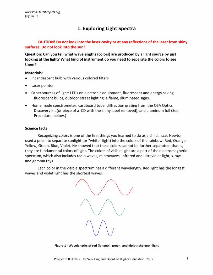
Each color in the visible spectrum has a different wavelength. Red light has the longest waves and violet light has the shortest waves.
Figure 1 -‐ Wavelengths of red (longest), green, and violet (shortest) light
www.PHOTONprojects.org July 2013
Project PHOTON2 © New England Board of Higher Education, 2005
4
Often the color that you see contains several of the fundamental colors of light. For example, a television screen or computer monitor displays many different colors, but if you look with a magnifier at the screen you will see only very tiny red, green and blue pixels. The combination of varying amounts of the three colors produces all the colors you see on the screen.
In this experiment you will examine the colors radiated by several different sources of light. When the colors are displayed in order of wavelength we call it the spectrum of the light source. A rainbow is the spectrum of sunlight! You could use a prism for this experiment, but prisms are a little difficult to work with. Like a prism, the diffraction grating in your optics kit can break light into a spectrum. To get the clearest spectra, you first need to construct a spectroscope, a device for looking at spectra. (A device that actually lets you measure the spectrum is called a spectrometer.) The tube of the spectroscope keeps out room light, and the pinhole on the end lets you focus on one light source at a time.
Procedure:
1. Making the spectroscope:
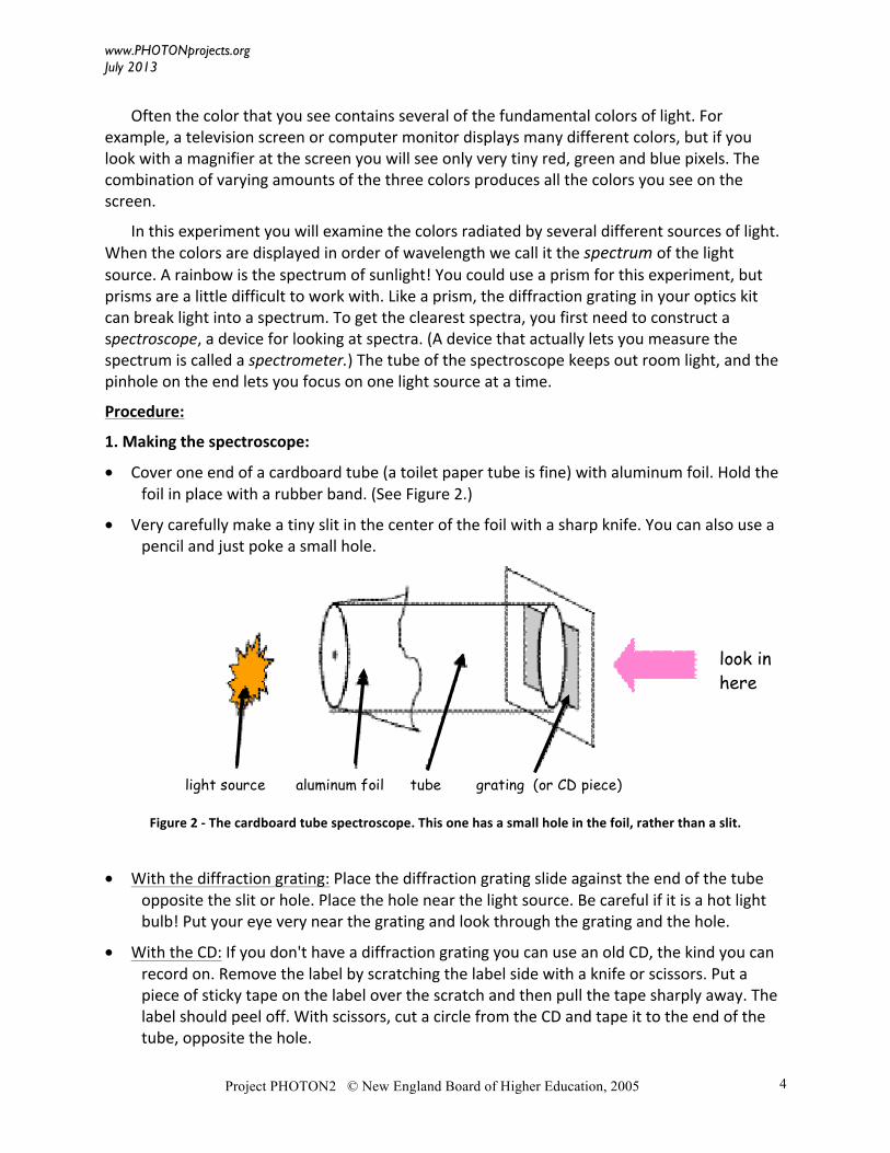
• Cover one end of a cardboard tube (a toilet paper tube is fine) with aluminum foil. Hold the foil in place with a rubber band. (See Figure 2.)
• Very carefully make a tiny slit in the center of the foil with a sharp knife. You can also use a pencil and just poke a small hole.
Figure 2 -‐ The cardboard tube spectroscope. This one has a small hole in the foil, rather than a slit.
• With the diffraction grating: Place the diffraction grating slide against the end of the tube opposite the slit or hole. Place the hole near the light source. Be careful if it is a hot light bulb! Put your eye very near the grating and look through the grating and the hole.
• With the CD: If you don't have a diffraction grating you can use an old CD, the kind you can record on. Remove the label by scratching the label side with a knife or scissors. Put a piece of sticky tape on the label over the scratch and then pull the tape sharply away. The label should peel off. With scissors, cut a circle from the CD and tape it to the end of the tube, opposite the hole.
light source aluminum foil tube grating (or CD piece)
look in here
www.PHOTONprojects.org July 2013
Project PHOTON2 © New England Board of Higher Education, 2005
5
2. Observing sources:
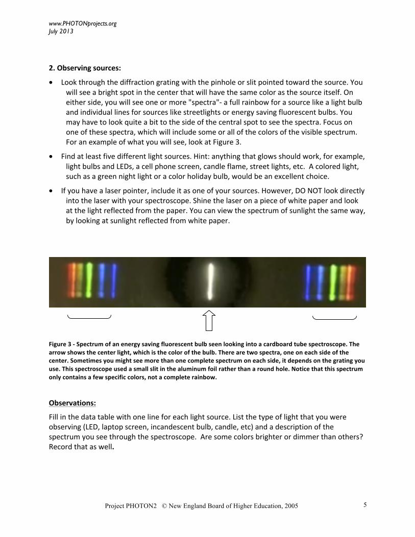
• Look through the diffraction grating with the pinhole or slit pointed toward the source. You will see a bright spot in the center that will have the same color as the source itself. On either side, you will see one or more "spectra"-‐ a full rainbow for a source like a light bulb and individual lines for sources like streetlights or energy saving fluorescent bulbs. You may have to look quite a bit to the side of the central spot to see the spectra. Focus on one of these spectra, which will include some or all of the colors of the visible spectrum. For an example of what you will see, look at Figure 3.
• Find at least five different light sources. Hint: anything that glows should work, for example, light bulbs and LEDs, a cell phone screen, candle flame, street lights, etc. A colored light, such as a green night light or a color holiday bulb, would be an excellent choice.
• If you have a laser pointer, include it as one of your sources. However, DO NOT look directly into the laser with your spectroscope. Shine the laser on a piece of white paper and look at the light reflected from the paper. You can view the spectrum of sunlight the same way, by looking at sunlight reflected from white paper.
Figure 3 -‐ Spectrum of an energy saving fluorescent bulb seen looking into a cardboard tube spectroscope. The arrow shows the center light, which is the color of the bulb. There are two spectra, one on each side of the center. Sometimes you might see more than one complete spectrum on each side, it depends on the grating you use. This spectroscope used a small slit in the aluminum foil rather than a round hole. Notice that this spectrum only contains a few specific colors, not a complete rainbow.
Observations:
Fill in the data table with one line for each light source. List the type of light that you were observing (LED, laptop screen, incandescent bulb, candle, etc) and a description of the spectrum you see through the spectroscope. Are some colors brighter or dimmer than others? Record that as well.
www.PHOTONprojects.org July 2013
Project PHOTON2 © New England Board of Higher Education, 2005
6
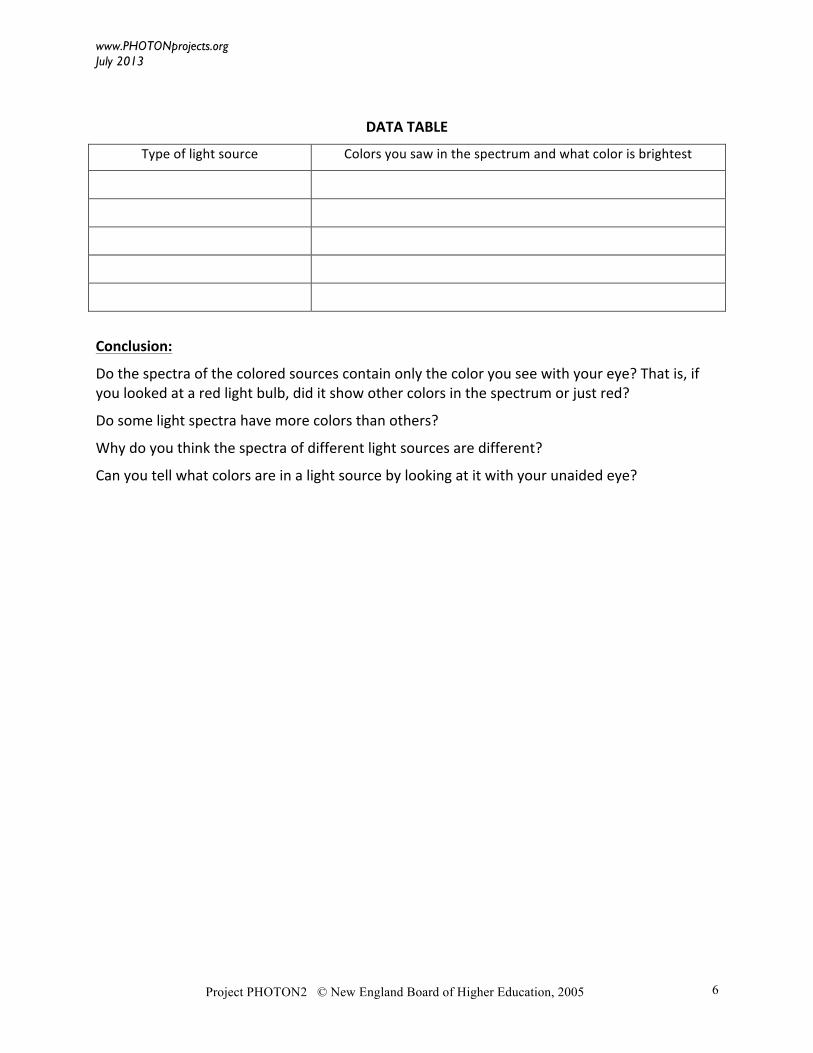
DATA TABLE
Type of light source Colors you saw in the spectrum and what color is brightest
Conclusion:
Do the spectra of the colored sources contain only the color you see with your eye? That is, if you looked at a red light bulb, did it show other colors in the spectrum or just red?
Do some light spectra have more colors than others?
Why do you think the spectra of different light sources are different?
Can you tell what colors are in a light source by looking at it with your unaided eye?
www.PHOTONprojects.org July 2013
Project PHOTON2 © New England Board of Higher Education, 2005
7
2. What Color is a Tomato?
Question: Can your eyes be fooled by the color of a light source? Can you make your friends think a tomato is a plum?
Materials:
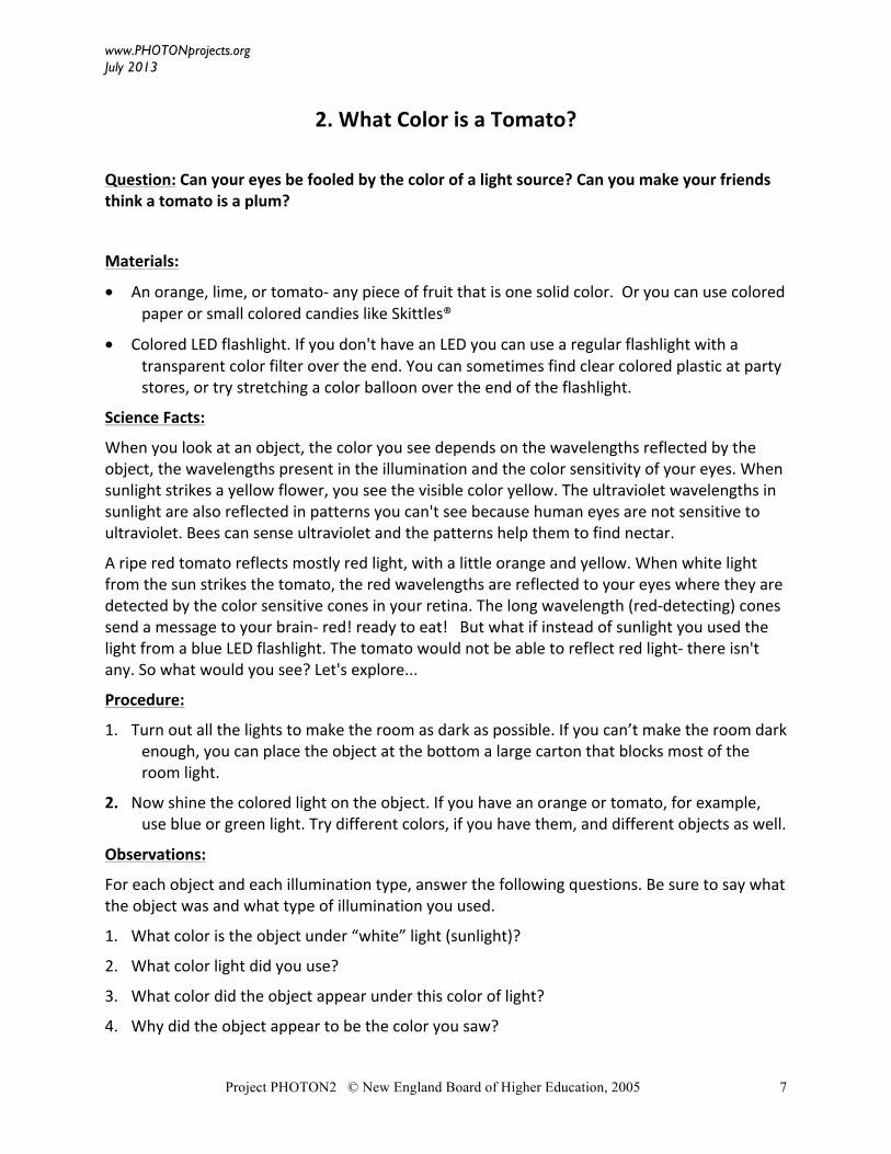
• An orange, lime, or tomato-‐ any piece of fruit that is one solid color. Or you can use colored paper or small colored candies like Skittles®
• Colored LED flashlight. If you don't have an LED you can use a regular flashlight with a transparent color filter over the end. You can sometimes find clear colored plastic at party stores, or try stretching a color balloon over the end of the flashlight.
Science Facts:
When you look at an object, the color you see depends on the wavelengths reflected by the object, the wavelengths present in the illumination and the color sensitivity of your eyes. When sunlight strikes a yellow flower, you see the visible color yellow. The ultraviolet wavelengths in sunlight are also reflected in patterns you can't see because human eyes are not sensitive to ultraviolet. Bees can sense ultraviolet and the patterns help them to find nectar.
A ripe red tomato reflects mostly red light, with a little orange and yellow. When white light from the sun strikes the tomato, the red wavelengths are reflected to your eyes where they are detected by the color sensitive cones in your retina. The long wavelength (red-‐detecting) cones send a message to your brain-‐ red! ready to eat! But what if instead of sunlight you used the light from a blue LED flashlight. The tomato would not be able to reflect red light-‐ there isn't any. So what would you see? Let's explore...
Procedure:
1. Turn out all the lights to make the room as dark as possible. If you can’t make the room dark enough, you can place the object at the bottom a large carton that blocks most of the room light.
2. Now shine the colored light on the object. If you have an orange or tomato, for example, use blue or green light. Try different colors, if you have them, and different objects as well.
Observations:
For each object and each illumination type, answer the following questions. Be sure to say what the object was and what type of illumination you used.
1. What color is the object under “white” light (sunlight)?
2. What color light did you use?
3. What color did the object appear under this color of light?
4. Why did the object appear to be the color you saw?
www.PHOTONprojects.org July 2013
Project PHOTON2 © New England Board of Higher Education, 2005
8
Conclusions And Applications:
1. What is necessary for you to be able to see the “true color” of an object?
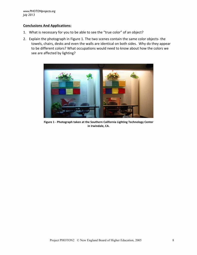
2. Explain the photograph in Figure 1. The two scenes contain the same color objects-‐ the towels, chairs, desks and even the walls are identical on both sides. Why do they appear to be different colors? What occupations would need to know about how the colors we see are affected by lighting?
Figure 1 -‐ Photograph taken at the Southern California Lighting Technology Center
in Irwindale, CA.
www.PHOTONprojects.org
July 2013
Project PHOTON2 © New England Board of Higher Education, 2005
9
3. Exploring Pinhole Images
Questions: How can you make an image (picture) with just a cardboard box and a pinhole?
Materials:
• Large carton or box with the bottom removed
• Aluminum foil
• Needle, tape
• Translucent paper, like vellum paper from a craft store or waxed paper
Science Facts:
A pinhole camera consists of a closed light-‐tight box with a small pinhole centered on one end. The pinhole is located where you might expect a lens to be in a regular camera. Like a lens, the pinhole can form an image on a screen.
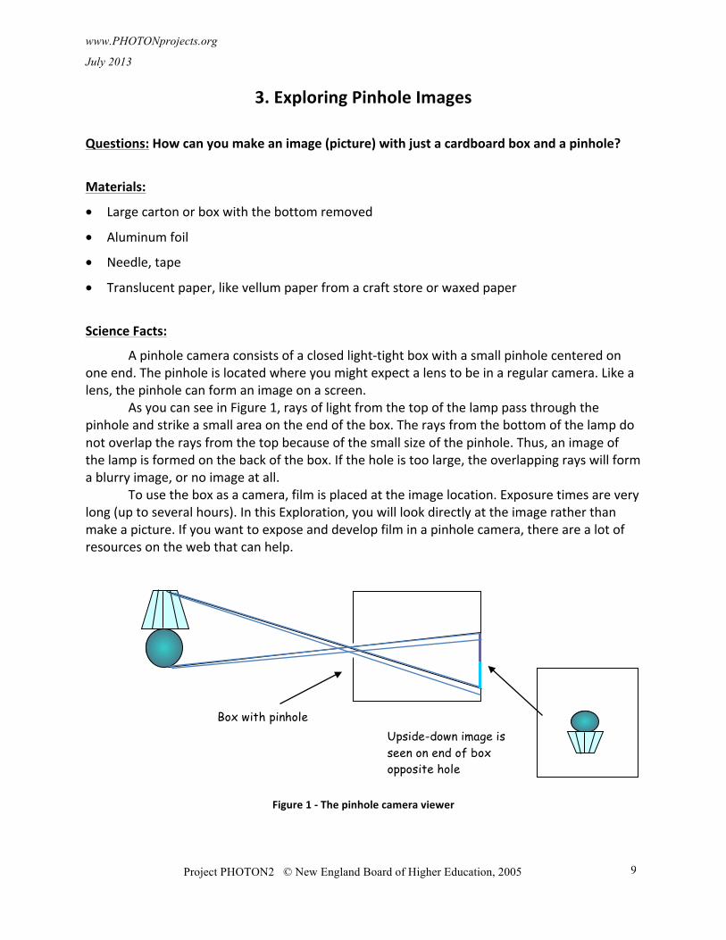
As you can see in Figure 1, rays of light from the top of the lamp pass through the pinhole and strike a small area on the end of the box. The rays from the bottom of the lamp do not overlap the rays from the top because of the small size of the pinhole. Thus, an image of the lamp is formed on the back of the box. If the hole is too large, the overlapping rays will form a blurry image, or no image at all.
To use the box as a camera, film is placed at the image location. Exposure times are very long (up to several hours). In this Exploration, you will look directly at the image rather than make a picture. If you want to expose and develop film in a pinhole camera, there are a lot of resources on the web that can help.
Figure 1 -‐ The pinhole camera viewer
Box with pinhole Upside-down image is seen on end of box opposite hole
www.PHOTONprojects.org
July 2013
Project PHOTON2 © New England Board of Higher Education, 2005
10
Procedure:
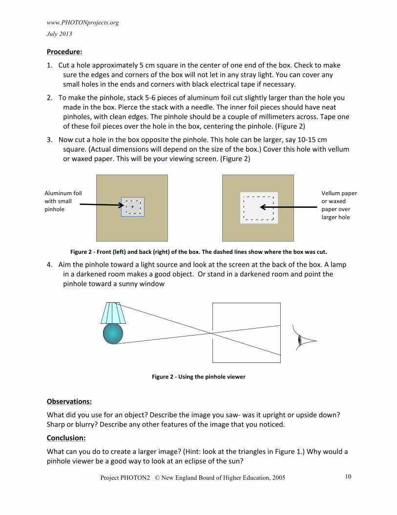
1. Cut a hole approximately 5 cm square in the center of one end of the box. Check to make sure the edges and corners of the box will not let in any stray light. You can cover any small holes in the ends and corners with black electrical tape if necessary.
2. To make the pinhole, stack 5-‐6 pieces of aluminum foil cut slightly larger than the hole you made in the box. Pierce the stack with a needle. The inner foil pieces should have neat pinholes, with clean edges. The pinhole should be a couple of millimeters across. Tape one of these foil pieces over the hole in the box, centering the pinhole. (Figure 2)
3. Now cut a hole in the box opposite the pinhole. This hole can be larger, say 10-‐15 cm square. (Actual dimensions will depend on the size of the box.) Cover this hole with vellum or waxed paper. This will be your viewing screen. (Figure 2)
Figure 2 -‐ Front (left) and back (right) of the box. The dashed lines show where the box was cut.
4. Aim the pinhole toward a light source and look at the screen at the back of the box. A lamp in a darkened room makes a good object. Or stand in a darkened room and point the pinhole toward a sunny window
Figure 2 -‐ Using the pinhole viewer
Observations:
What did you use for an object? Describe the image you saw-‐ was it upright or upside down? Sharp or blurry? Describe any other features of the image that you noticed.
Conclusion:
What can you do to create a larger image? (Hint: look at the triangles in Figure 1.) Why would a pinhole viewer be a good way to look at an eclipse of the sun?
Aluminum foil with small pinhole
Vellum paper or waxed paper over larger hole
www.PHOTONprojects.org
July 2013
Project PHOTON2 © New England Board of Higher Education, 2005.
11
4. Exploring Reflection from Transparent Objects
Questions: If an object is transparent how can you see it? Can you make a glass disappear?
Materials:
• Two Pyrex® beakers – one larger and one smaller, sized so that the smaller beaker fits inside the larger beaker. You can also use a test tube and a beaker. Experiment to see what kind of glass works!
• Vegetable oil (enough to fill the larger beaker)
Science Facts:
In order for you to see something, light must go from the object to your eyes. A glowing object like a light bulb emits light that you can see directly, but other objects must reflect light for you to see them.
Whenever light travels from one medium to another (for example, from air into glass or glass into water) part of the light is reflected and part of the light is transmitted into the second material. The amount of light reflected depends on the index of refraction of the two materials.
The index of refraction of a material is the calculated by dividing the speed of light in a vacuum by the speed of light in the material. For example, glass has an index of refraction of 1.5, which means that light travels 1.5 times faster in a vacuum than in glass. Usually when scientists talk about how fast light travels they use the index of refraction rather than the actual speed.
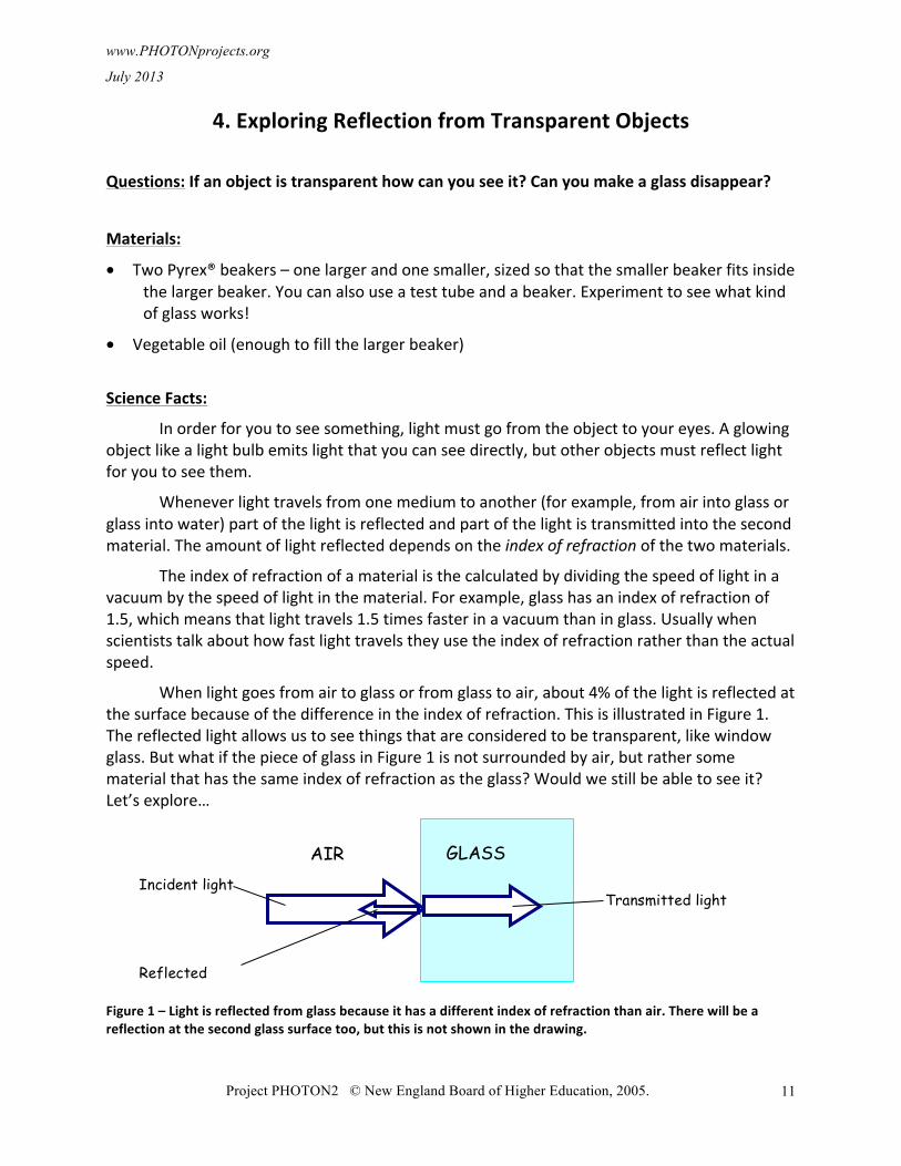
When light goes from air to glass or from glass to air, about 4% of the light is reflected at the surface because of the difference in the index of refraction. This is illustrated in Figure 1. The reflected light allows us to see things that are considered to be transparent, like window glass. But what if the piece of glass in Figure 1 is not surrounded by air, but rather some material that has the same index of refraction as the glass? Would we still be able to see it? Let’s explore…
Figure 1 – Light is reflected from glass because it has a different index of refraction than air. There will be a reflection at the second glass surface too, but this is not shown in the drawing.
AIR GLASS Incident light
Reflected light
Transmitted light
www.PHOTONprojects.org
July 2013
Project PHOTON2 © New England Board of Higher Education, 2005.
12
Procedure:
1. Place the smaller beaker in the larger beaker.
Can you see the smaller beaker?
Why can you see the smaller beaker? (Think about index of refraction.)
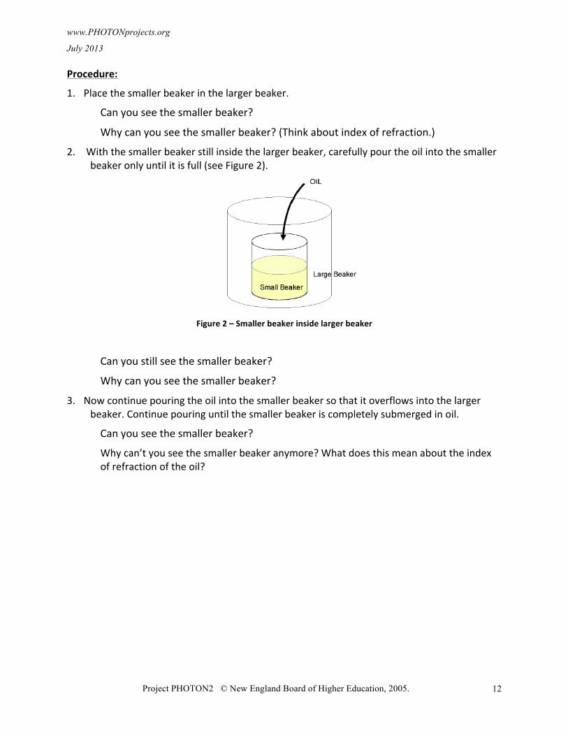
2. With the smaller beaker still inside the larger beaker, carefully pour the oil into the smaller beaker only until it is full (see Figure 2).
Figure 2 – Smaller beaker inside larger beaker
Can you still see the smaller beaker?
Why can you see the smaller beaker?
3. Now continue pouring the oil into the smaller beaker so that it overflows into the larger beaker. Continue pouring until the smaller beaker is completely submerged in oil.
Can you see the smaller beaker?
Why can’t you see the smaller beaker anymore? What does this mean about the index of refraction of the oil?
www.PHOTONprojects.org July 2013
Project PHOTON2 © New England Board of Higher Education, 2005
13
5. Laser Target Shoot
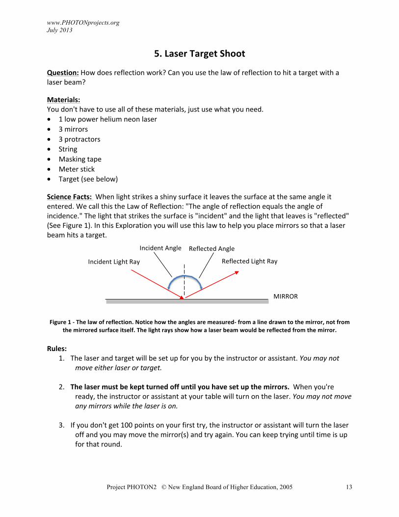
Question: How does reflection work? Can you use the law of reflection to hit a target with a laser beam? Materials: You don't have to use all of these materials, just use what you need. • 1 low power helium neon laser • 3 mirrors • 3 protractors • String • Masking tape • Meter stick • Target (see below) Science Facts: When light strikes a shiny surface it leaves the surface at the same angle it entered. We call this the Law of Reflection: "The angle of reflection equals the angle of incidence." The light that strikes the surface is "incident" and the light that leaves is "reflected" (See Figure 1). In this Exploration you will use this law to help you place mirrors so that a laser beam hits a target.
Figure 1 -‐ The law of reflection. Notice how the angles are measured-‐ from a line drawn to the mirror, not from
the mirrored surface itself. The light rays show how a laser beam would be reflected from the mirror. Rules:
1. The laser and target will be set up for you by the instructor or assistant. You may not move either laser or target.
2. The laser must be kept turned off until you have set up the mirrors. When you're ready, the instructor or assistant at your table will turn on the laser. You may not move any mirrors while the laser is on.
3. If you don't get 100 points on your first try, the instructor or assistant will turn the laser off and you may move the mirror(s) and try again. You can keep trying until time is up for that round.
Incident Light Ray
MIRROR
Reflected Light Ray
Incident Angle Reflected Angle
www.PHOTONprojects.org July 2013
Project PHOTON2 © New England Board of Higher Education, 2005
14
4. If the laser falls on a line between regions of the target, you will be awarded the average of the points on either side.
5. The mirrors must be at least 25 cm from the laser and from each other. The Challenge:
Round 1: You have 10 minutes to hit the target using ONE mirror. Round 2: You have 15 minutes to hit the target using TWO mirrors. Round 3: You have 20 minutes to hit the target using THREE mirrors. In each round, the highest score will be recorded.
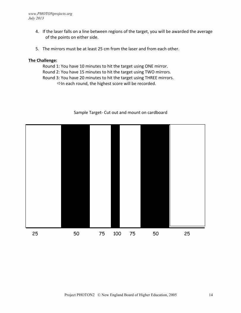
Sample Target-‐ Cut out and mount on cardboard
25 50 75 100 75 50 25
www.PHOTONprojects.org
July 2013
Project PHOTON2 © New England Board of Higher Education, 2005
15
6. Exploring Refraction (Gelatin Optics)
CAUTION! Do not look into the laser or at any reflections of the laser from shiny surfaces.
Question: How does light bend when it changes its speed? How do lenses change the path of light?
Materials:
• Stiff blocks of gelatin, about 2 cm thick
• Round cookie cutter, strips cut from a plastic folder, a ruler or toothpicks for cutting
• Light source -‐ focusable flashlight, laser or ray box if available
Note on gelatin: You can follow the recipe for Jigglers on the Jello® brand package. Sugarless yellow (lemon) works well. Plain gelatin may also be used. A very stiff gel is needed-‐ use one-‐third the usual amount of water for each packet of gelatin. Use hot (boiling) water only and stir very well. Pour into pans, allowing the gelatin to be 2-‐3 cm thick. Place in the refrigerator. (However, it will usually gel at room temperature if the room is not too warm.)
Note on light sources: Laser pointers are best. If there is a problem obtaining enough laser pointers, or if safety is an issue, a flashlight can be used for most experiments. A physics “ray box,” which is a special light source that produces one to five collimated “rays” of light, works best.
Science Facts:
In a vacuum, light travels at 300,000,000 meters per second or 186,000 miles per second. When light enters a transparent medium, it slows down and its wavelength (the distance between wave crests) shortens. Because of this, a beam of light traveling from one substance to another may change direction.
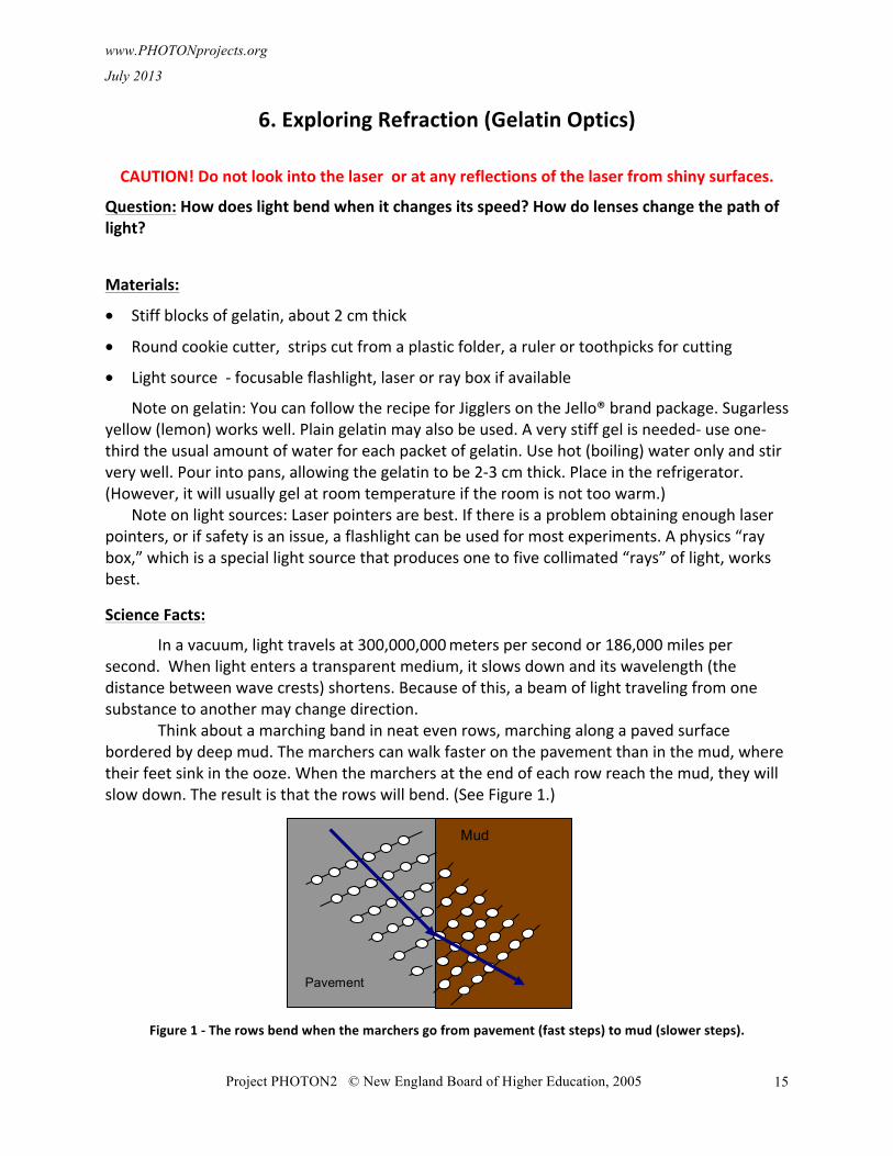
Think about a marching band in neat even rows, marching along a paved surface bordered by deep mud. The marchers can walk faster on the pavement than in the mud, where their feet sink in the ooze. When the marchers at the end of each row reach the mud, they will slow down. The result is that the rows will bend. (See Figure 1.)
Figure 1 -‐ The rows bend when the marchers go from pavement (fast steps) to mud (slower steps).
Pavement
Mud
www.PHOTONprojects.org
July 2013
Project PHOTON2 © New England Board of Higher Education, 2005
16
Waves behave in a similar fashion. In Figure 1, the rows of marchers are like the crests of waves. You can see how waves will bend when they go from a medium where they travel fast to a medium where they move more slowly, for example, if waves go from air into water or glass.
The bending of waves as they go from one medium to another is called refraction. Refraction of light explains many things you see around you every day, such as the apparent bending of a spoon when it is partially submerged in water and how lenses, including those in eyeglasses, work.
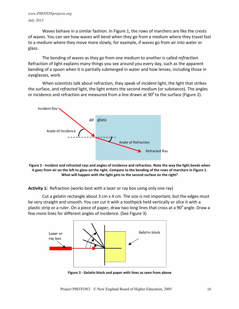
When scientists talk about refraction, they speak of incident light, the light that strikes the surface, and refracted light, the light enters the second medium (or substance). The angles or incidence and refraction are measured from a line drawn at 90o to the surface (Figure 2).
Figure 2 -‐ Incident and refracted rays and angles of incidence and refraction. Note the way the light bends when it goes from air on the left to glass on the right. Compare to the bending of the rows of marchers in Figure 1.
What will happen with the light gets to the second surface on the right?
Activity 1: Refraction (works best with a laser or ray box using only one ray)
Cut a gelatin rectangle about 3 cm x 4 cm. The size is not important, but the edges must be very straight and smooth. You can cut it with a toothpick held vertically or slice it with a plastic strip or a ruler. On a piece of paper, draw two long lines that cross at a 90o angle. Draw a few more lines for different angles of incidence. (See Figure 3)
Figure 3 -‐ Gelatin block and paper with lines as seen from above
Incident Ray
Angle of Refraction
1
Angle of Incidence
2
A
Refracted Ray
air glass
www.PHOTONprojects.org
July 2013
Project PHOTON2 © New England Board of Higher Education, 2005
17
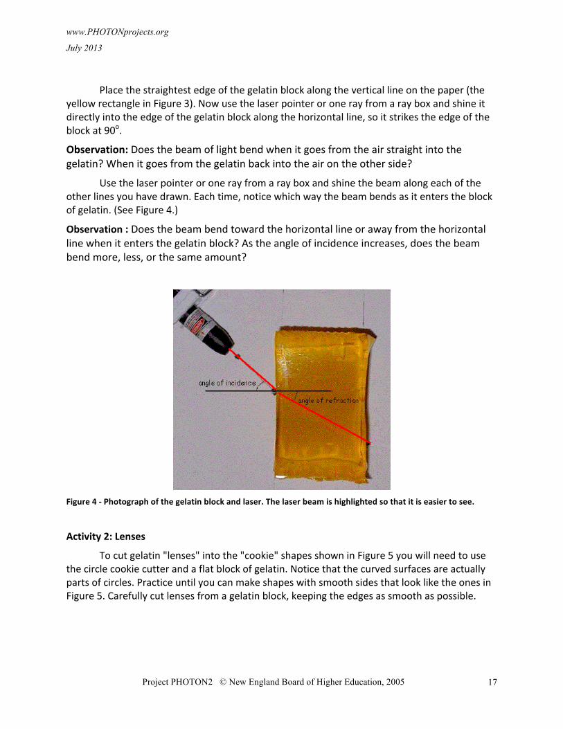
Place the straightest edge of the gelatin block along the vertical line on the paper (the yellow rectangle in Figure 3). Now use the laser pointer or one ray from a ray box and shine it directly into the edge of the gelatin block along the horizontal line, so it strikes the edge of the block at 90o.
Observation: Does the beam of light bend when it goes from the air straight into the gelatin? When it goes from the gelatin back into the air on the other side?
Use the laser pointer or one ray from a ray box and shine the beam along each of the other lines you have drawn. Each time, notice which way the beam bends as it enters the block of gelatin. (See Figure 4.)
Observation : Does the beam bend toward the horizontal line or away from the horizontal line when it enters the gelatin block? As the angle of incidence increases, does the beam bend more, less, or the same amount?
Figure 4 -‐ Photograph of the gelatin block and laser. The laser beam is highlighted so that it is easier to see.
Activity 2: Lenses
To cut gelatin "lenses" into the "cookie" shapes shown in Figure 5 you will need to use the circle cookie cutter and a flat block of gelatin. Notice that the curved surfaces are actually parts of circles. Practice until you can make shapes with smooth sides that look like the ones in Figure 5. Carefully cut lenses from a gelatin block, keeping the edges as smooth as possible.
www.PHOTONprojects.org
July 2013
Project PHOTON2 © New England Board of Higher Education, 2005
18
Figure 5 -‐ Lens shapes cut of a gelatin block using a circle cookie cutter. The circles show the position of the cookie cutter. The yellow shaded shapes are the gelatin "lenses" that you will use for this experiment.
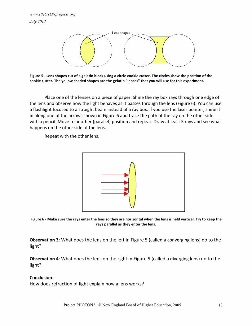
Place one of the lenses on a piece of paper. Shine the ray box rays through one edge of the lens and observe how the light behaves as it passes through the lens (Figure 6). You can use a flashlight focused to a straight beam instead of a ray box. If you use the laser pointer, shine it in along one of the arrows shown in Figure 6 and trace the path of the ray on the other side with a pencil. Move to another (parallel) position and repeat. Draw at least 5 rays and see what happens on the other side of the lens.
Repeat with the other lens.
Figure 6 -‐ Make sure the rays enter the lens so they are horizontal when the lens is held vertical. Try to keep the
rays parallel as they enter the lens.
Observation 3: What does the lens on the left in Figure 5 (called a converging lens) do to the light? Observation 4: What does the lens on the right in Figure 5 (called a diverging lens) do to the light? Conclusion: How does refraction of light explain how a lens works?
www.PHOTONprojects.org July 2013
Project PHOTON2 © New England Board of Higher Education, 2005
19
7. Exploring Lenses -‐ The Magic Lens CAUTION! Do not look into the laser or at any reflections of the laser from shiny surfaces.
Question: Can you make a lens out of air and use it in water? How will it behave compared to a glass lens used in air?
Materials: • Two watch glasses (these are used in a chemistry laboratory) • Tube of silicone caulk, like bathroom or aquarium caulk • Fish tank large enough to hold the lens • Focusable flashlight or laser beam or optics ray box • Clamps to hold the lens in place in the tank (optional)
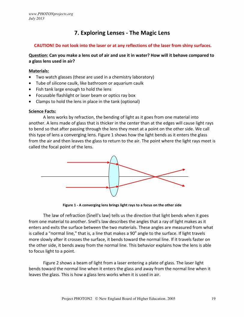
Science Facts: A lens works by refraction, the bending of light as it goes from one material into
another. A lens made of glass that is thicker in the center than at the edges will cause light rays to bend so that after passing through the lens they meet at a point on the other side. We call this type of lens a converging lens. Figure 1 shows how the light bends as it enters the glass from the air and then leaves the glass to return to the air. The point where the light rays meet is called the focal point of the lens.
Figure 1 -‐ A converging lens brings light rays to a focus on the other side
The law of refraction (Snell's law) tells us the direction that light bends when it goes from one material to another. Snell's law describes the angles that a ray of light makes as it enters and exits the surface between the two materials. These angles are measured from what is called a "normal line," that is, a line that makes a 90o angle to the surface. If light travels more slowly after it crosses the surface, it bends toward the normal line. If it travels faster on the other side, it bends away from the normal line. This behavior explains how the lens is able to focus light to a point.
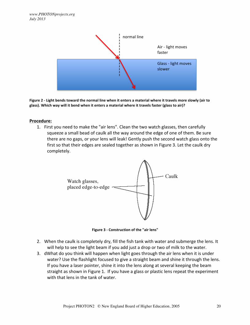
Figure 2 shows a beam of light from a laser entering a plate of glass. The laser light bends toward the normal line when it enters the glass and away from the normal line when it leaves the glass. This is how a glass lens works when it is used in air.
www.PHOTONprojects.org July 2013
Project PHOTON2 © New England Board of Higher Education, 2005
20
Figure 2 -‐ Light bends toward the normal line when it enters a material where it travels more slowly (air to glass). Which way will it bend when it enters a material where it travels faster (glass to air)? Procedure:
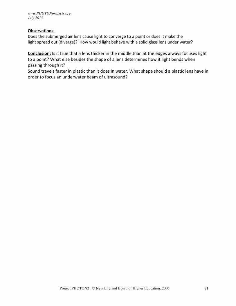
1. First you need to make the "air lens". Clean the two watch glasses, then carefully squeeze a small bead of caulk all the way around the edge of one of them. Be sure there are no gaps, or your lens will leak! Gently push the second watch glass onto the first so that their edges are sealed together as shown in Figure 3. Let the caulk dry completely.
Figure 3 -‐ Construction of the "air lens"
2. When the caulk is completely dry, fill the fish tank with water and submerge the lens. It will help to see the light beam if you add just a drop or two of milk to the water.
3. dWhat do you think will happen when light goes through the air lens when it is under water? Use the flashlight focused to give a straight beam and shine it through the lens. If you have a laser pointer, shine it into the lens along at several keeping the beam straight as shown in Figure 1. If you have a glass or plastic lens repeat the experiment with that lens in the tank of water.
Air -‐ light moves faster Glass -‐ light moves slower
normal line
www.PHOTONprojects.org July 2013
Project PHOTON2 © New England Board of Higher Education, 2005
21
Observations: Does the submerged air lens cause light to converge to a point or does it make the light spread out (diverge)? How would light behave with a solid glass lens under water? Conclusion: Is it true that a lens thicker in the middle than at the edges always focuses light to a point? What else besides the shape of a lens determines how it light bends when passing through it? Sound travels faster in plastic than it does in water. What shape should a plastic lens have in order to focus an underwater beam of ultrasound?
www.PHOTONprojects.org July 2013
Project PHOTON2 © New England Board of Higher Education, 2005
22
8. Exploring Diffraction
CAUTION! Do not look into the laser or at any reflections of the laser from shiny surfaces.
Question: How can you use a laser to measure the thickness of your hair?
Materials:
• Laser Pointer • Tape measure or ruler • 2 clothes pins or a partner to hold the laser steady • Paper and tape
Science Facts:
Imagine a tree standing in the sunlight. Behind it on the grass is a shadow where the leaves, branches and trunk blocked the sunlight from continuing onto the ground. Shadows caused by large objects like trees and people look very much like the object, although the shadow may be distorted depending on where the light is. However, when light passes through a very small opening or around a very small object, patterns of dark and light form that may look nothing like the object. This is called diffraction.
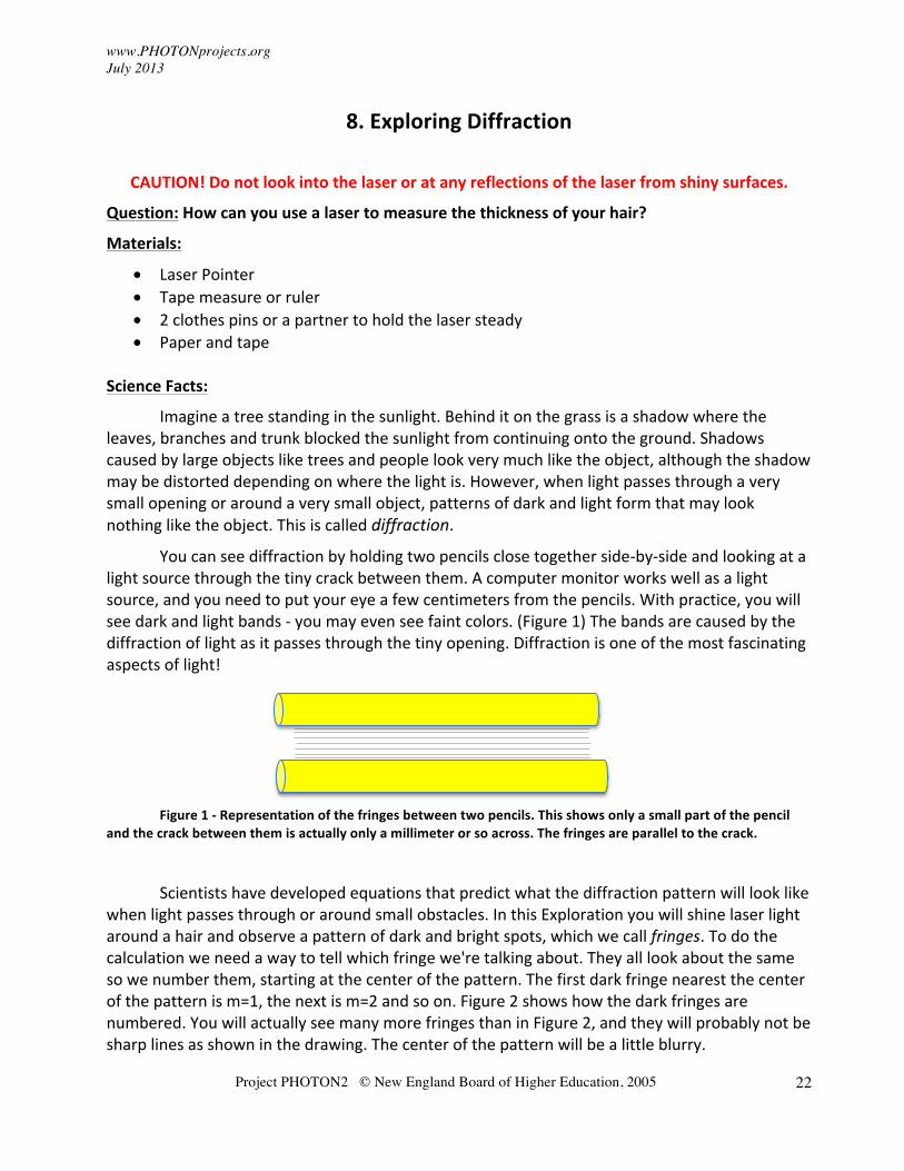
You can see diffraction by holding two pencils close together side-‐by-‐side and looking at a light source through the tiny crack between them. A computer monitor works well as a light source, and you need to put your eye a few centimeters from the pencils. With practice, you will see dark and light bands -‐ you may even see faint colors. (Figure 1) The bands are caused by the diffraction of light as it passes through the tiny opening. Diffraction is one of the most fascinating aspects of light!
Figure 1 -‐ Representation of the fringes between two pencils. This shows only a small part of the pencil
and the crack between them is actually only a millimeter or so across. The fringes are parallel to the crack.
Scientists have developed equations that predict what the diffraction pattern will look like when light passes through or around small obstacles. In this Exploration you will shine laser light around a hair and observe a pattern of dark and bright spots, which we call fringes. To do the calculation we need a way to tell which fringe we're talking about. They all look about the same so we number them, starting at the center of the pattern. The first dark fringe nearest the center of the pattern is m=1, the next is m=2 and so on. Figure 2 shows how the dark fringes are numbered. You will actually see many more fringes than in Figure 2, and they will probably not be sharp lines as shown in the drawing. The center of the pattern will be a little blurry.
www.PHOTONprojects.org July 2013
Project PHOTON2 © New England Board of Higher Education, 2005
23
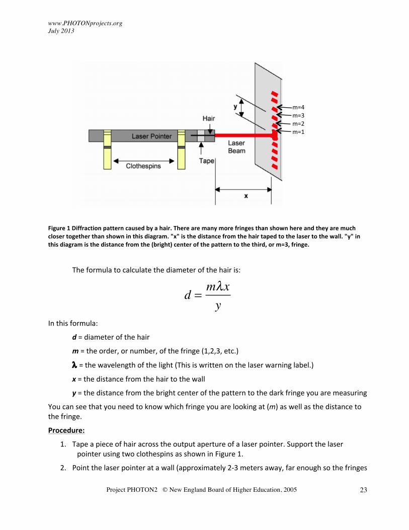
Figure 1 Diffraction pattern caused by a hair. There are many more fringes than shown here and they are much closer together than shown in this diagram. "x" is the distance from the hair taped to the laser to the wall. "y" in this diagram is the distance from the (bright) center of the pattern to the third, or m=3, fringe.
The formula to calculate the diameter of the hair is:
d =mλxy
In this formula:
d = diameter of the hair
m = the order, or number, of the fringe (1,2,3, etc.)
λ = the wavelength of the light (This is written on the laser warning label.)
x = the distance from the hair to the wall
y = the distance from the bright center of the pattern to the dark fringe you are measuring
You can see that you need to know which fringe you are looking at (m) as well as the distance to the fringe.
Procedure:
1. Tape a piece of hair across the output aperture of a laser pointer. Support the laser pointer using two clothespins as shown in Figure 1.
2. Point the laser pointer at a wall (approximately 2-‐3 meters away, far enough so the fringes
m=4 m=3 m=2 m=1
www.PHOTONprojects.org July 2013
Project PHOTON2 © New England Board of Higher Education, 2005
24
are separate enough to measure). Tape a piece of paper to the wall to serve as a screen that you can write on. (Please don't write on the wall!)
3. Turn on the laser pointer and observe the pattern formed on the wall. Describe what this pattern looks like. Does it look like the shadow of a hair? Are there many fringes or just a few? Are they clear or blurry?
4. With a pencil, mark the center of the pattern. Call this y =0. Mark the positions of several dark fringes on either side and number them (m = 1 for the closest to the center, then m=2, etc)
5. Measure the distance from the laser pointer to the wall and record the value of x. Take the paper down.
6. Measure the distance between the center of the pattern (y=0) and one of the other fringes. Also record m, the order of the fringe whose distance you measured. Record the values of y and m.
7. Record the wavelength of the laser. It should be listed on the side of the laser pointer (typically 650 nm). Be sure the laser is off when you look for the label!
8. Using the equation to calculate the diameter of the hair. It should be approximately 70-‐100 um.
Conclusions:
Compare your results with your classmates. Is there a difference between blonde and brown hair? Some students have measured the size of their pets’ hair! What might be a practical use of this experiment?
Data for the Diffraction Experiment
Type of hair you used (color, coarse or fine, etc): _________________________
x = ___________________
m = ___________________
y = ___________________
λ = ___________________
Calculated hair diameter: ____________________________
www.PHOTONprojects.org
Project PHOTON2 © New England Board of Higher Education, 2005
25
9. Exploring Rayleigh's Criterion and Resolution
Question: How close together can words be on a sign so you can still read it from a distance? How close can stars be to be seen as separate objects? Does it depend on wavelength (color)?
Materials:
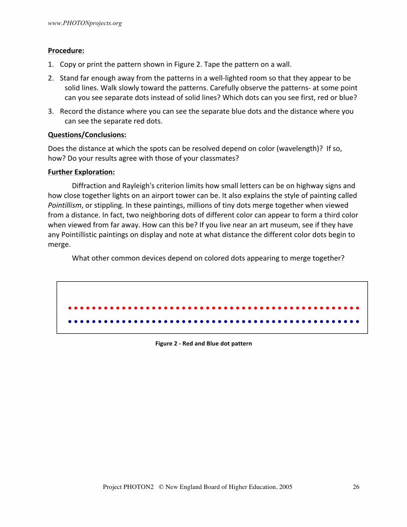
• Patterns of red dots and blue dots, 1 mm across, spaced 1 mm apart. Draw them on a piece of paper or print Figure 2 on white paper using a color printer.
• Meter stick
Science Facts:
When light passes through a small opening, it spreads out, or diffracts. The diffraction pattern that results from light passing through a small round hole consists of a central bright spot (called the Airy disk) surrounded by dimmer rings of light around the disk in bulls eye fashion. The size of the center disk depends on the wavelength of the light, the size of the hole and on how far the hole is from the viewing screen. It might surprise you to learn that light passing through a small hole spreads more than light passing through a larger hole! Red light also spreads out more than blue light.
When light from two small points of light (like stars) pass through the same hole (like
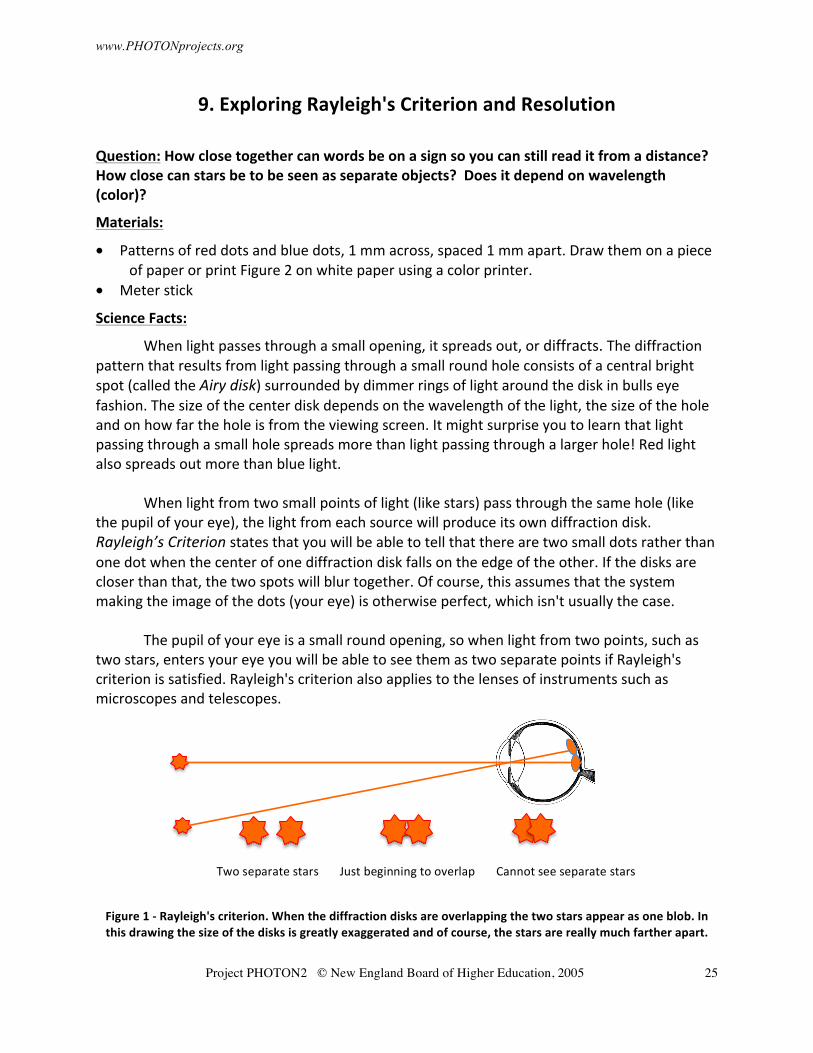
the pupil of your eye), the light from each source will produce its own diffraction disk. Rayleigh’s Criterion states that you will be able to tell that there are two small dots rather than one dot when the center of one diffraction disk falls on the edge of the other. If the disks are closer than that, the two spots will blur together. Of course, this assumes that the system making the image of the dots (your eye) is otherwise perfect, which isn't usually the case.
The pupil of your eye is a small round opening, so when light from two points, such as
two stars, enters your eye you will be able to see them as two separate points if Rayleigh's criterion is satisfied. Rayleigh's criterion also applies to the lenses of instruments such as microscopes and telescopes.
Figure 1 -‐ Rayleigh's criterion. When the diffraction disks are overlapping the two stars appear as one blob. In this drawing the size of the disks is greatly exaggerated and of course, the stars are really much farther apart.
Two separate stars Just beginning to overlap Cannot see separate stars
www.PHOTONprojects.org
Project PHOTON2 © New England Board of Higher Education, 2005
26
Procedure:
1. Copy or print the pattern shown in Figure 2. Tape the pattern on a wall.
2. Stand far enough away from the patterns in a well-‐lighted room so that they appear to be solid lines. Walk slowly toward the patterns. Carefully observe the patterns-‐ at some point can you see separate dots instead of solid lines? Which dots can you see first, red or blue?
3. Record the distance where you can see the separate blue dots and the distance where you can see the separate red dots.
Questions/Conclusions:
Does the distance at which the spots can be resolved depend on color (wavelength)? If so, how? Do your results agree with those of your classmates?
Further Exploration:
Diffraction and Rayleigh's criterion limits how small letters can be on highway signs and how close together lights on an airport tower can be. It also explains the style of painting called Pointillism, or stippling. In these paintings, millions of tiny dots merge together when viewed from a distance. In fact, two neighboring dots of different color can appear to form a third color when viewed from far away. How can this be? If you live near an art museum, see if they have any Pointillistic paintings on display and note at what distance the different color dots begin to merge.
What other common devices depend on colored dots appearing to merge together?
Figure 2 -‐ Red and Blue dot pattern
www.PHOTONprojects.org July 2013
Project PHOTON2 © New England Board of Higher Education, 2005
27
10. Exploring Polarization
Question: What is polarized light? How is polarized light produced? What is polarized light used for?
Materials:
• Two pieces of polarizing plastic from the OSA Optics Discovery kit. These are square, dark pieces of plastic covered by a thin plastic film. Remove the film to do the experiments.
• Bowl of water
• Transparent plastic objects: ruler, protractor, comb, etc.
Science Facts:
Imagine you and a friend are holding the ends of a rope. You shake your end up and down and waves travel down the rope to your friend. You could also shake the end of the rope side to side or in another back and forth direction and the waves you make will change their vibration direction to match.
Like the waves you made on a rope, the vibrations of light waves are perpendicular to
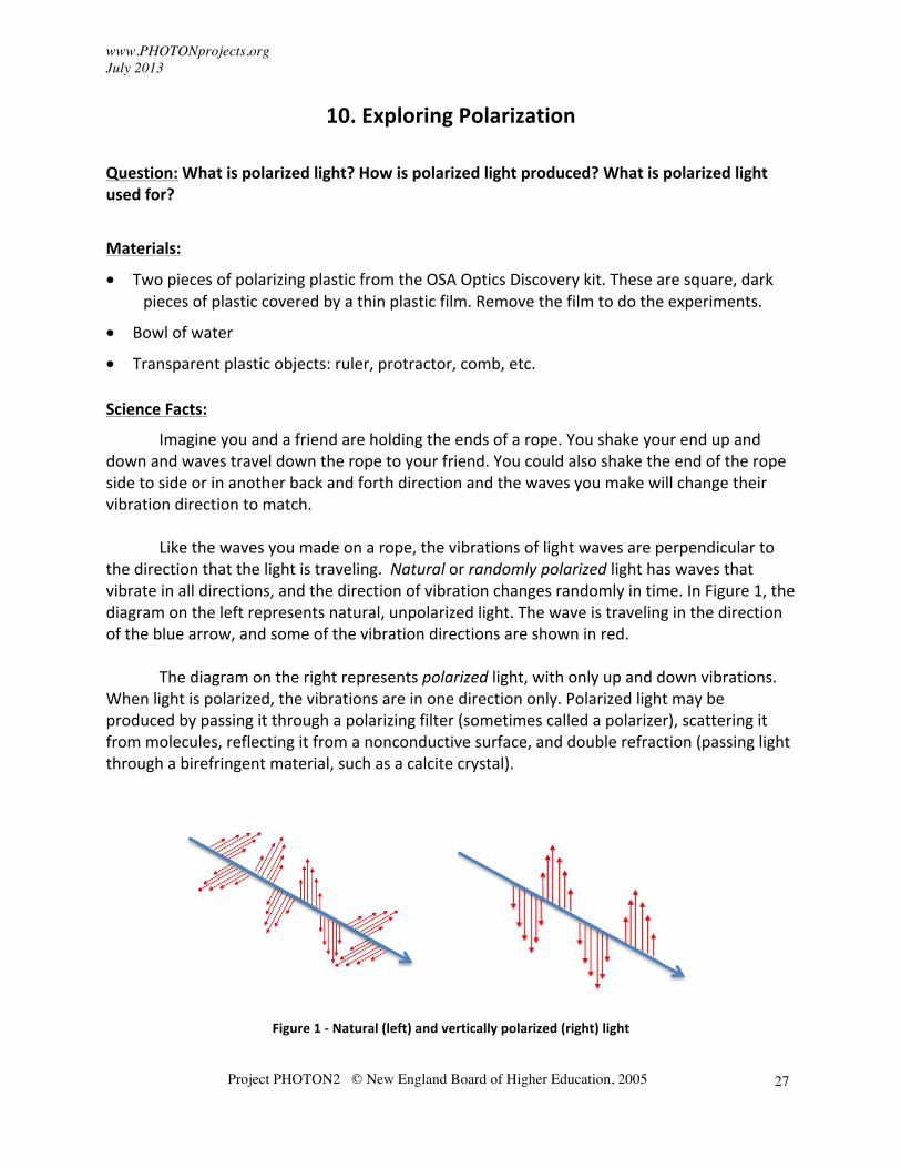
the direction that the light is traveling. Natural or randomly polarized light has waves that vibrate in all directions, and the direction of vibration changes randomly in time. In Figure 1, the diagram on the left represents natural, unpolarized light. The wave is traveling in the direction of the blue arrow, and some of the vibration directions are shown in red.
The diagram on the right represents polarized light, with only up and down vibrations.
When light is polarized, the vibrations are in one direction only. Polarized light may be produced by passing it through a polarizing filter (sometimes called a polarizer), scattering it from molecules, reflecting it from a nonconductive surface, and double refraction (passing light through a birefringent material, such as a calcite crystal).
Figure 1 -‐ Natural (left) and vertically polarized (right) light
www.PHOTONprojects.org July 2013
Project PHOTON2 © New England Board of Higher Education, 2005
28
Procedure:
1. Find the transmission axis of the polarizers (Polarization by reflection) The transmission axis determines the direction of vibration of light waves after they
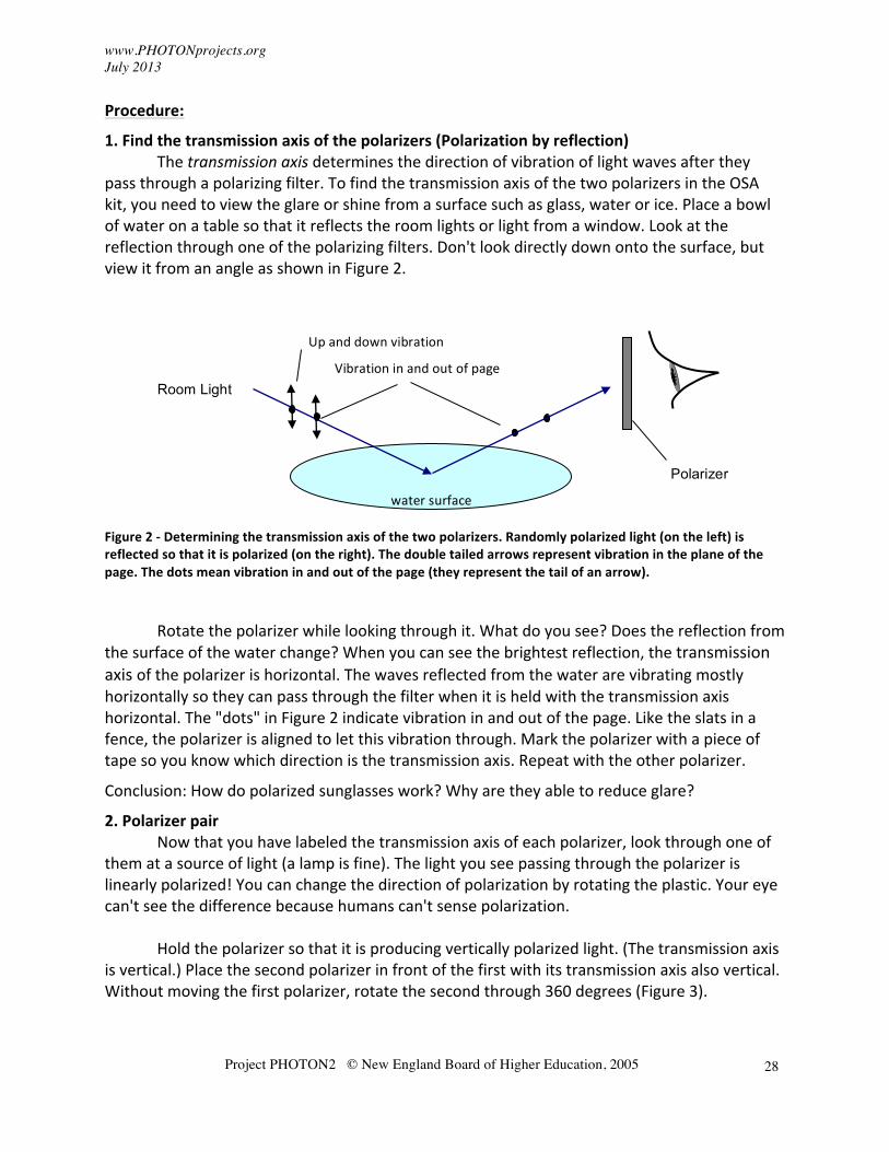
pass through a polarizing filter. To find the transmission axis of the two polarizers in the OSA kit, you need to view the glare or shine from a surface such as glass, water or ice. Place a bowl of water on a table so that it reflects the room lights or light from a window. Look at the reflection through one of the polarizing filters. Don't look directly down onto the surface, but view it from an angle as shown in Figure 2.
Figure 2 -‐ Determining the transmission axis of the two polarizers. Randomly polarized light (on the left) is reflected so that it is polarized (on the right). The double tailed arrows represent vibration in the plane of the page. The dots mean vibration in and out of the page (they represent the tail of an arrow).
Rotate the polarizer while looking through it. What do you see? Does the reflection from the surface of the water change? When you can see the brightest reflection, the transmission axis of the polarizer is horizontal. The waves reflected from the water are vibrating mostly horizontally so they can pass through the filter when it is held with the transmission axis horizontal. The "dots" in Figure 2 indicate vibration in and out of the page. Like the slats in a fence, the polarizer is aligned to let this vibration through. Mark the polarizer with a piece of tape so you know which direction is the transmission axis. Repeat with the other polarizer.
Conclusion: How do polarized sunglasses work? Why are they able to reduce glare?
2. Polarizer pair Now that you have labeled the transmission axis of each polarizer, look through one of them at a source of light (a lamp is fine). The light you see passing through the polarizer is linearly polarized! You can change the direction of polarization by rotating the plastic. Your eye can't see the difference because humans can't sense polarization.
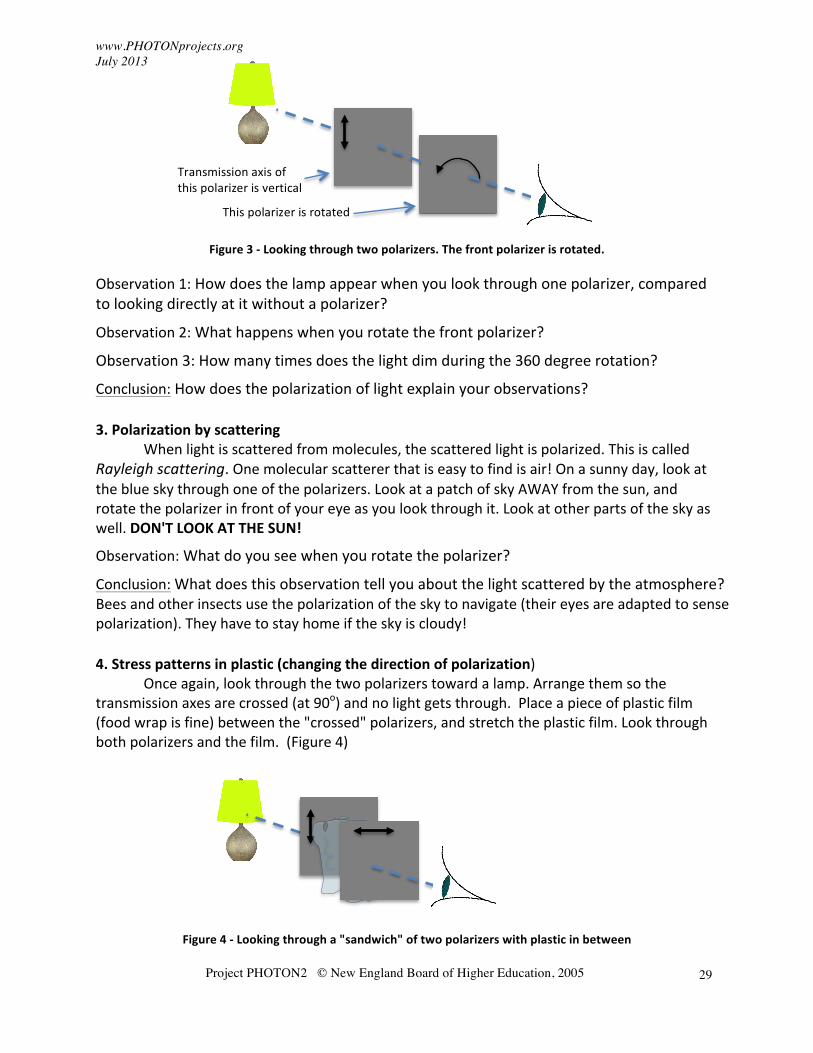
Hold the polarizer so that it is producing vertically polarized light. (The transmission axis is vertical.) Place the second polarizer in front of the first with its transmission axis also vertical. Without moving the first polarizer, rotate the second through 360 degrees (Figure 3).
Polarizer
Room Light
Up and down vibration
Vibration in and out of page
water surface
www.PHOTONprojects.org July 2013
Project PHOTON2 © New England Board of Higher Education, 2005
29
Figure 3 -‐ Looking through two polarizers. The front polarizer is rotated.
Observation 1: How does the lamp appear when you look through one polarizer, compared to looking directly at it without a polarizer?
Observation 2: What happens when you rotate the front polarizer?
Observation 3: How many times does the light dim during the 360 degree rotation?
Conclusion: How does the polarization of light explain your observations?
3. Polarization by scattering When light is scattered from molecules, the scattered light is polarized. This is called Rayleigh scattering. One molecular scatterer that is easy to find is air! On a sunny day, look at the blue sky through one of the polarizers. Look at a patch of sky AWAY from the sun, and rotate the polarizer in front of your eye as you look through it. Look at other parts of the sky as well. DON'T LOOK AT THE SUN!
Observation: What do you see when you rotate the polarizer?
Conclusion: What does this observation tell you about the light scattered by the atmosphere? Bees and other insects use the polarization of the sky to navigate (their eyes are adapted to sense polarization). They have to stay home if the sky is cloudy!
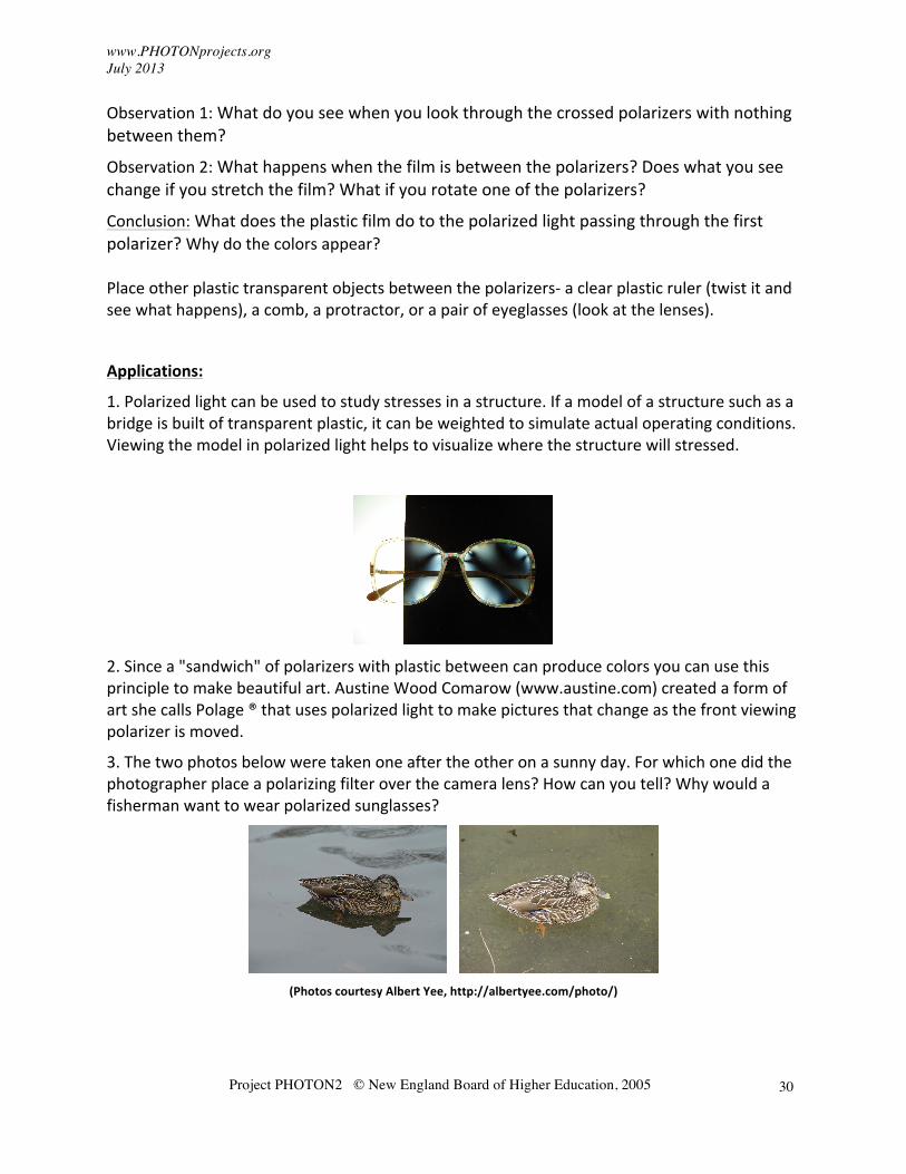
4. Stress patterns in plastic (changing the direction of polarization) Once again, look through the two polarizers toward a lamp. Arrange them so the transmission axes are crossed (at 90o) and no light gets through. Place a piece of plastic film (food wrap is fine) between the "crossed" polarizers, and stretch the plastic film. Look through both polarizers and the film. (Figure 4)
Figure 4 -‐ Looking through a "sandwich" of two polarizers with plastic in between
Transmission axis of this polarizer is vertical
This polarizer is rotated
www.PHOTONprojects.org July 2013
Project PHOTON2 © New England Board of Higher Education, 2005
30
Observation 1: What do you see when you look through the crossed polarizers with nothing between them?
Observation 2: What happens when the film is between the polarizers? Does what you see change if you stretch the film? What if you rotate one of the polarizers?
Conclusion: What does the plastic film do to the polarized light passing through the first polarizer? Why do the colors appear? Place other plastic transparent objects between the polarizers-‐ a clear plastic ruler (twist it and see what happens), a comb, a protractor, or a pair of eyeglasses (look at the lenses).
Applications:
1. Polarized light can be used to study stresses in a structure. If a model of a structure such as a bridge is built of transparent plastic, it can be weighted to simulate actual operating conditions. Viewing the model in polarized light helps to visualize where the structure will stressed.
2. Since a "sandwich" of polarizers with plastic between can produce colors you can use this principle to make beautiful art. Austine Wood Comarow (www.austine.com) created a form of art she calls Polage ® that uses polarized light to make pictures that change as the front viewing polarizer is moved.
3. The two photos below were taken one after the other on a sunny day. For which one did the photographer place a polarizing filter over the camera lens? How can you tell? Why would a fisherman want to wear polarized sunglasses?
(Photos courtesy Albert Yee, http://albertyee.com/photo/)
www.PHOTONprojects.org July 2013
Project PHOTON2 © New England Board of Higher Education, 2005
31
11. The Magic Box -‐ Fun with Polarization
Question: Can you use light to make a magic box with a "wall that isn't there"? Where does the wall come from? Why can you push your finger through it with no resistance?
Materials:
• A small rectangular box such as a shoe box or tissue box
• Four 2" or 3" square linear polarizing filters
• Tape
• For special effect-‐ a chopstick or long bladed knife (be careful!)
Science facts:
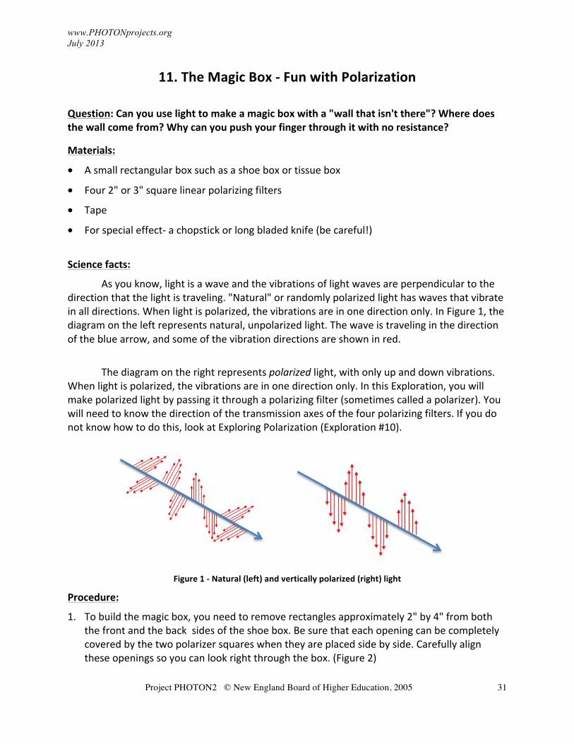
As you know, light is a wave and the vibrations of light waves are perpendicular to the direction that the light is traveling. "Natural" or randomly polarized light has waves that vibrate in all directions. When light is polarized, the vibrations are in one direction only. In Figure 1, the diagram on the left represents natural, unpolarized light. The wave is traveling in the direction of the blue arrow, and some of the vibration directions are shown in red.
The diagram on the right represents polarized light, with only up and down vibrations.
When light is polarized, the vibrations are in one direction only. In this Exploration, you will make polarized light by passing it through a polarizing filter (sometimes called a polarizer). You will need to know the direction of the transmission axes of the four polarizing filters. If you do not know how to do this, look at Exploring Polarization (Exploration #10).
Figure 1 -‐ Natural (left) and vertically polarized (right) light
Procedure:
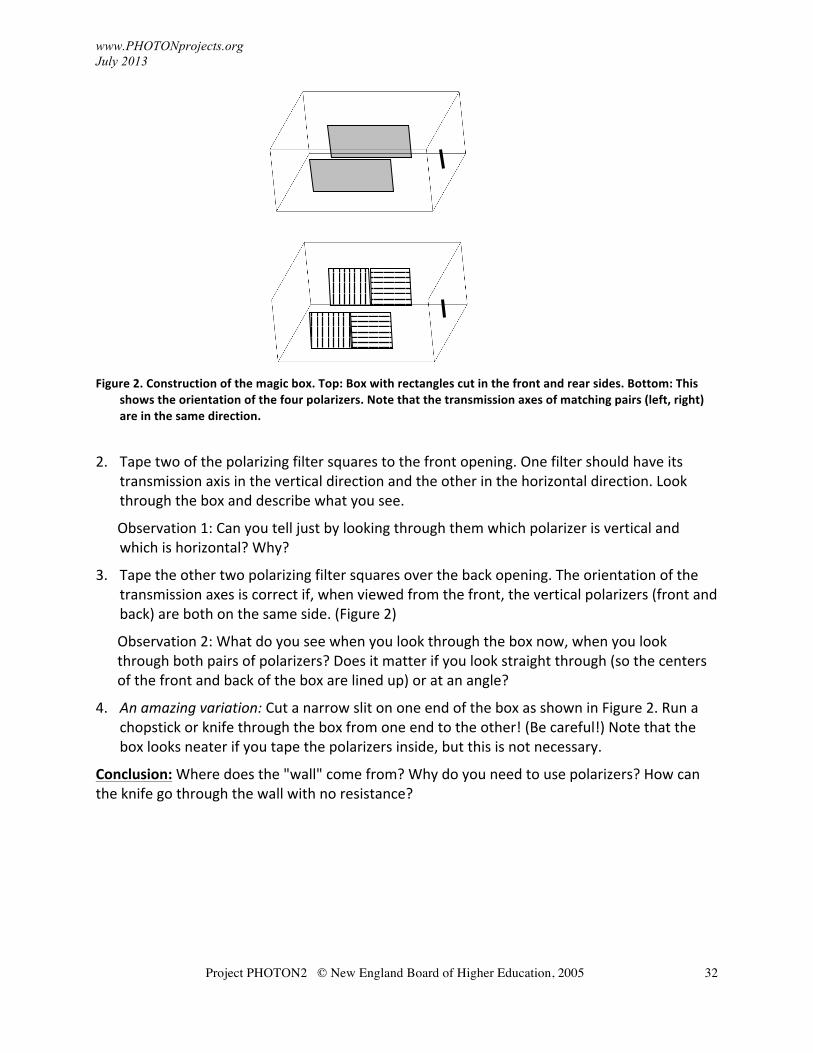
1. To build the magic box, you need to remove rectangles approximately 2" by 4" from both the front and the back sides of the shoe box. Be sure that each opening can be completely covered by the two polarizer squares when they are placed side by side. Carefully align these openings so you can look right through the box. (Figure 2)
www.PHOTONprojects.org July 2013
Project PHOTON2 © New England Board of Higher Education, 2005
32
Figure 2. Construction of the magic box. Top: Box with rectangles cut in the front and rear sides. Bottom: This
shows the orientation of the four polarizers. Note that the transmission axes of matching pairs (left, right) are in the same direction.
2. Tape two of the polarizing filter squares to the front opening. One filter should have its transmission axis in the vertical direction and the other in the horizontal direction. Look through the box and describe what you see.
Observation 1: Can you tell just by looking through them which polarizer is vertical and which is horizontal? Why?
3. Tape the other two polarizing filter squares over the back opening. The orientation of the transmission axes is correct if, when viewed from the front, the vertical polarizers (front and back) are both on the same side. (Figure 2)
Observation 2: What do you see when you look through the box now, when you look through both pairs of polarizers? Does it matter if you look straight through (so the centers of the front and back of the box are lined up) or at an angle?
4. An amazing variation: Cut a narrow slit on one end of the box as shown in Figure 2. Run a chopstick or knife through the box from one end to the other! (Be careful!) Note that the box looks neater if you tape the polarizers inside, but this is not necessary.
Conclusion: Where does the "wall" come from? Why do you need to use polarizers? How can the knife go through the wall with no resistance?
www.PHOTONprojects.org July 2013
Project PHOTON2 © New England Board of Higher Education, 2005
33
12. Polarized Light Art
Question: Can you use polarized light to make a colorful picture? Materials:
• Two pieces of polarizing plastic from the OSA kit. These are square, dark pieces of plastic covered by a thin plastic film. Remove the protective film to do the experiments.
• Pieces of cellophane tape (clear packing tape works well) or you can use the cellophane wrapping material from produce such as lettuce or broccoli.
• A small square of clear plastic the same size as the polarizers
Science Facts:
Before you use polarized light to create art, you should do the polarized light Exploration in this booklet. In Exploring Polarized Light, you learn that “natural" or randomly polarized light consists of light waves that vibrate in all directions. When light is polarized, the vibrations are in one direction only. In this exploration, you will create polarized light by using a polarizing filter.
In Exploring Polarized Light you also learn that if you place two pieces of polarizing filter so the transmission axes are parallel, nearly all the light passes. If the transmission axes are at right angles, no light passes. But if you put certain types of material in between the crossed polarizers, some light may get through and colors may appear from clear colorless material.
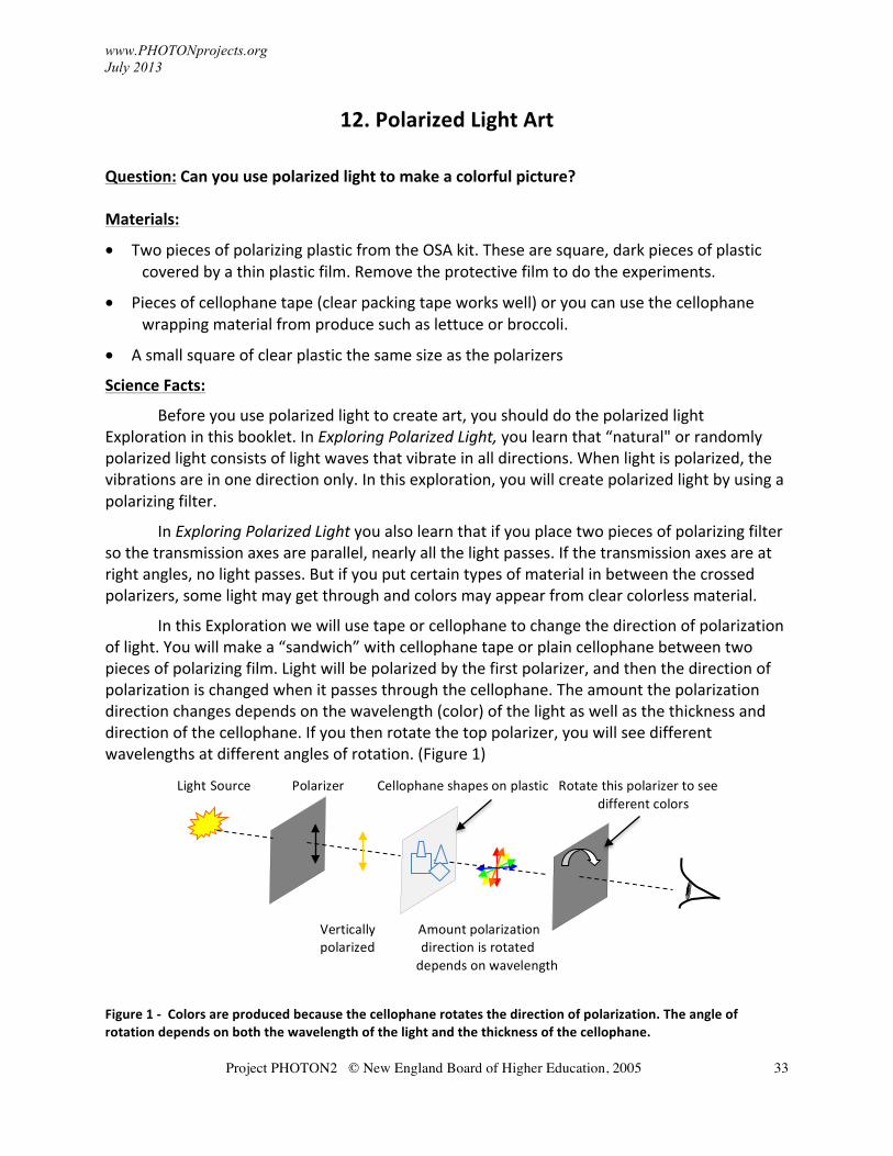
In this Exploration we will use tape or cellophane to change the direction of polarization of light. You will make a “sandwich” with cellophane tape or plain cellophane between two pieces of polarizing film. Light will be polarized by the first polarizer, and then the direction of polarization is changed when it passes through the cellophane. The amount the polarization direction changes depends on the wavelength (color) of the light as well as the thickness and direction of the cellophane. If you then rotate the top polarizer, you will see different wavelengths at different angles of rotation. (Figure 1)
Figure 1 -‐ Colors are produced because the cellophane rotates the direction of polarization. The angle of rotation depends on both the wavelength of the light and the thickness of the cellophane.
Vertically Amount polarization polarized direction is rotated depends on wavelength
Light Source Polarizer Cellophane shapes on plastic Rotate this polarizer to see different colors
www.PHOTONprojects.org July 2013
Project PHOTON2 © New England Board of Higher Education, 2005
34
Procedure: 1. Cut the pieces of cellophane or tape into various shapes. Experiment by varying the
thickness of the shapes from one to several layers thick. 2. Stick the tape onto the plastic square. If you use plain cellophane you can attach it with a
glue stick. The reason you should use a separate piece of plastic is to protect the polarizing film; it might be damaged if you attach the pieces to it directly.
NOTE: Not everything sold as "cellophane" is really cellophane (which is made from cellulose). Some plastic films sold as cellulose don't work very well in this experiment. Try a variety of materials and see what works best! 3. When your piece of “art” is complete, place it on one of the polarizers and hold it up to a
window or other light source. Put the other polarizer in front of the tape and rotate it, while looking through all three layers.
Conclusions:
Did the thickness and direction of the cellophane make a difference in the color you saw? What other materials would this work with besides cellophane?
More on polarized light art: Austine Woods Comorow is a well-‐known artist who uses this technique, which she calls Polage®, to create beautiful works of art that change as you look at them through a moving polarizer. Some of her pieces cover complete walls in museums and other public spaces. You can see her art on her website http://www.austine.com.
For more on polarization in nature, visit http://www.polarization.com.
www.PHOTONprojects.org July 2013
Project PHOTON2 © New England Board of Higher Education, 2005
35
13. Exploring Scattering
Question: Why is the sky blue?
Materials:
• 1 fishtank (A small container will not work as well.)
• 1 flashlight
• Several drops of milk or cream
Science Facts:
Why is the sky blue? Science did not begin to find an answer to that question until the mid 1800s. Sunlight, as you know, contains into all the colors of the rainbow. When sunlight passes through the atmosphere, the shorter (bluer) wavelengths are scattered in all directions by the tiny molecules of gas (mainly nitrogen and oxygen). Longer (redder) wavelengths travel in straighter lines with much less scattering. This is called Rayleigh scattering. "Sky blue" is not a single blue wavelength because the light from the sky includes a small amount of other scattered colors as well.
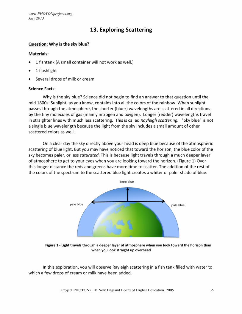
On a clear day the sky directly above your head is deep blue because of the atmospheric
scattering of blue light. But you may have noticed that toward the horizon, the blue color of the sky becomes paler, or less saturated. This is because light travels through a much deeper layer of atmosphere to get to your eyes when you are looking toward the horizon. (Figure 1) Over this longer distance the reds and greens have more time to scatter. The addition of the rest of the colors of the spectrum to the scattered blue light creates a whiter or paler shade of blue.
Figure 1 -‐ Light travels through a deeper layer of atmosphere when you look toward the horizon than when you look straight up overhead
In this exploration, you will observe Rayleigh scattering in a fish tank filled with water to
which a few drops of cream or milk have been added.
deep blue
pale blue pale blue
www.PHOTONprojects.org July 2013
Project PHOTON2 © New England Board of Higher Education, 2005
36
Procedure:
1. Fill the fish tank with at least 5 cm of water and add one or two drops of milk. Mix the water and milk in the tank so that it looks just barely cloudy. Too much milk will ruin this experiment, so you need to add it one drop at a time and observe the results before adding more.
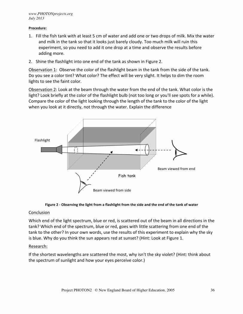
2. Shine the flashlight into one end of the tank as shown in Figure 2.
Observation 1: Observe the color of the flashlight beam in the tank from the side of the tank. Do you see a color tint? What color? The effect will be very slight. It helps to dim the room lights to see the faint color.
Observation 2: Look at the beam through the water from the end of the tank. What color is the light? Look briefly at the color of the flashlight bulb (not too long or you'll see spots for a while). Compare the color of the light looking through the length of the tank to the color of the light when you look at it directly, not through the water. Explain the difference
Figure 2 -‐ Observing the light from a flashlight from the side and the end of the tank of water
Conclusion
Which end of the light spectrum, blue or red, is scattered out of the beam in all directions in the tank? Which end of the spectrum, blue or red, goes with little scattering from one end of the tank to the other? In your own words, use the results of this experiment to explain why the sky is blue. Why do you think the sun appears red at sunset? (Hint: Look at Figure 1.
Research:
If the shortest wavelengths are scattered the most, why isn't the sky violet? (Hint: think about the spectrum of sunlight and how your eyes perceive color.)
Beam viewed from side
Flashlight
Fish tank Beam viewed from end
www.PHOTONprojects.org July 2013
Project PHOTON2 © New England Board of Higher Education, 2005
37
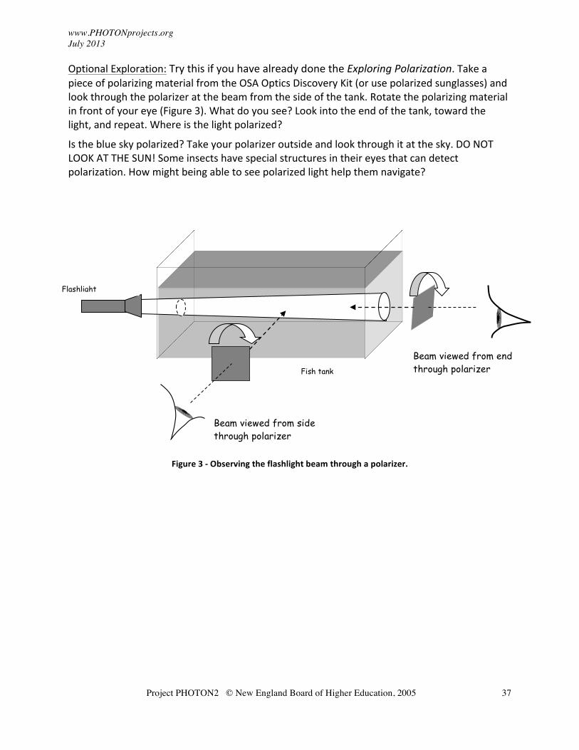
Optional Exploration: Try this if you have already done the Exploring Polarization. Take a piece of polarizing material from the OSA Optics Discovery Kit (or use polarized sunglasses) and look through the polarizer at the beam from the side of the tank. Rotate the polarizing material in front of your eye (Figure 3). What do you see? Look into the end of the tank, toward the light, and repeat. Where is the light polarized?
Is the blue sky polarized? Take your polarizer outside and look through it at the sky. DO NOT LOOK AT THE SUN! Some insects have special structures in their eyes that can detect polarization. How might being able to see polarized light help them navigate?
Figure 3 -‐ Observing the flashlight beam through a polarizer.
Flashlight
Fish tank
Beam viewed from side through polarizer
Beam viewed from end through polarizer
www.photonprojects.org July 2013
Project PHOTON2 © New England Board of Higher Education, 2005 38
14. Exploring Laser Beams
CAUTION! Do not look into the laser cavity or at any reflections of the laser from shiny surfaces. Question: Does laser light spread out as the beam travels through space? How else is a laser beam different from a flashlight? Materials:
• Laser pointer
• Flashlight
• Diffraction grating from the OSA Optics Discovery kit or a CD or DVD
• Piece of waxed paper or frosted glass
• Meter stick and ruler
Science Facts:
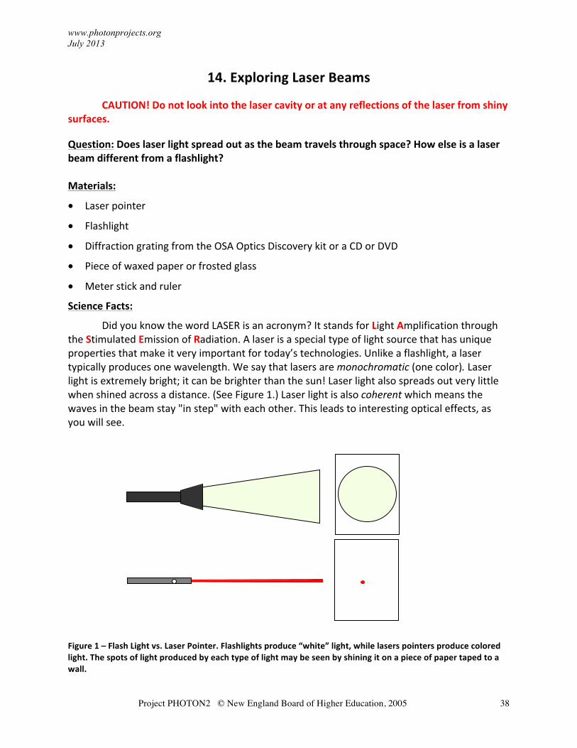
Did you know the word LASER is an acronym? It stands for Light Amplification through the Stimulated Emission of Radiation. A laser is a special type of light source that has unique properties that make it very important for today’s technologies. Unlike a flashlight, a laser typically produces one wavelength. We say that lasers are monochromatic (one color). Laser light is extremely bright; it can be brighter than the sun! Laser light also spreads out very little when shined across a distance. (See Figure 1.) Laser light is also coherent which means the waves in the beam stay "in step" with each other. This leads to interesting optical effects, as you will see.
Figure 1 – Flash Light vs. Laser Pointer. Flashlights produce “white” light, while lasers pointers produce colored light. The spots of light produced by each type of light may be seen by shining it on a piece of paper taped to a wall.
www.photonprojects.org July 2013
Project PHOTON2 © New England Board of Higher Education, 2005 39
The special properties of laser beams allow them to:
• Travel very far distances (to the moon and back!)
• Be focused down to very small spots (to less than 1/10 the size of a human hair) for cutting, welding, and drilling steel, ceramics and other really hard materials
• Make very precise measurements (like measuring the size of an atom)
• Cut tissue in laser surgery without blood
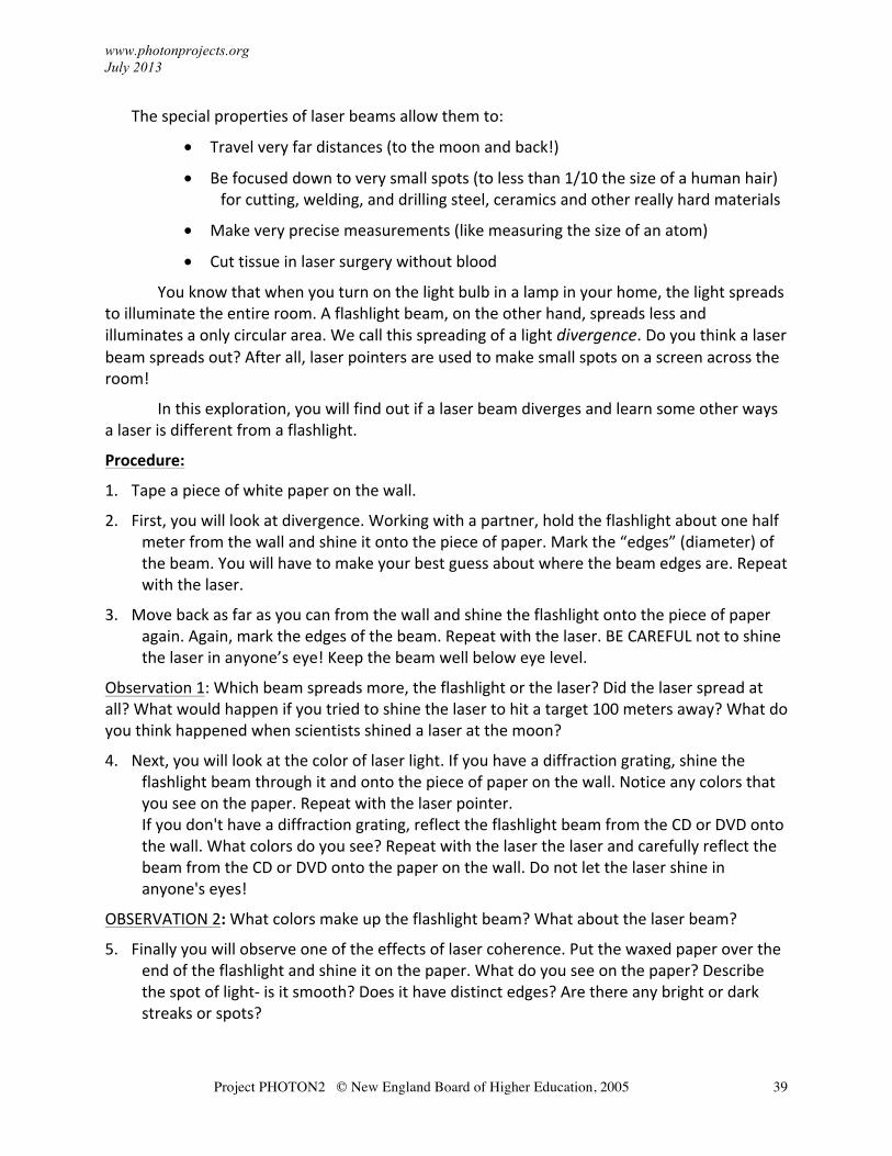
You know that when you turn on the light bulb in a lamp in your home, the light spreads to illuminate the entire room. A flashlight beam, on the other hand, spreads less and illuminates a only circular area. We call this spreading of a light divergence. Do you think a laser beam spreads out? After all, laser pointers are used to make small spots on a screen across the room!
In this exploration, you will find out if a laser beam diverges and learn some other ways a laser is different from a flashlight.
Procedure:
1. Tape a piece of white paper on the wall.
2. First, you will look at divergence. Working with a partner, hold the flashlight about one half meter from the wall and shine it onto the piece of paper. Mark the “edges” (diameter) of the beam. You will have to make your best guess about where the beam edges are. Repeat with the laser.
3. Move back as far as you can from the wall and shine the flashlight onto the piece of paper again. Again, mark the edges of the beam. Repeat with the laser. BE CAREFUL not to shine the laser in anyone’s eye! Keep the beam well below eye level.
Observation 1: Which beam spreads more, the flashlight or the laser? Did the laser spread at all? What would happen if you tried to shine the laser to hit a target 100 meters away? What do you think happened when scientists shined a laser at the moon?
4. Next, you will look at the color of laser light. If you have a diffraction grating, shine the flashlight beam through it and onto the piece of paper on the wall. Notice any colors that you see on the paper. Repeat with the laser pointer. If you don't have a diffraction grating, reflect the flashlight beam from the CD or DVD onto the wall. What colors do you see? Repeat with the laser the laser and carefully reflect the beam from the CD or DVD onto the paper on the wall. Do not let the laser shine in anyone's eyes!
OBSERVATION 2: What colors make up the flashlight beam? What about the laser beam?
5. Finally you will observe one of the effects of laser coherence. Put the waxed paper over the end of the flashlight and shine it on the paper. What do you see on the paper? Describe the spot of light-‐ is it smooth? Does it have distinct edges? Are there any bright or dark streaks or spots?
www.photonprojects.org July 2013
Project PHOTON2 © New England Board of Higher Education, 2005 40
6. Repeat step 6 with the laser. Does the laser light look different (aside from being red)? Do you notice any shimmering spots? What happens if you move the laser? if you move your head?
OBSERVATION 3: Describe how laser speckle is different from ordinary light.
Optional Exploration-‐ Use math to predict the size of a laser beam at a distance from you. You will need to carefully measure the diameter of the beam at two different distances from the lasers. You also need to measure the distance between the wall and the laser each time.
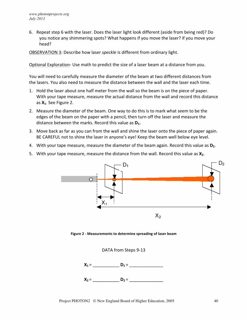
1. Hold the laser about one half meter from the wall so the beam is on the piece of paper. With your tape measure, measure the actual distance from the wall and record this distance as X1. See Figure 2.
2. Measure the diameter of the beam. One way to do this is to mark what seem to be the edges of the beam on the paper with a pencil, then turn off the laser and measure the distance between the marks. Record this value as D1.
3. Move back as far as you can from the wall and shine the laser onto the piece of paper again. BE CAREFUL not to shine the laser in anyone’s eye! Keep the beam well below eye level.
4. With your tape measure, measure the diameter of the beam again. Record this value as D2.
5. With your tape measure, measure the distance from the wall. Record this value as X2.
Figure 2 -‐ Measurements to determine spreading of laser beam
DATA from Steps 9-‐13
X1 = ___________ D1 = ______________
X2 = ___________ D2 = ______________
www.photonprojects.org July 2013
Project PHOTON2 © New England Board of Higher Education, 2005 41
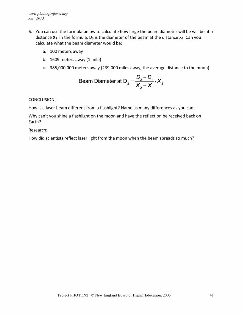
6. You can use the formula below to calculate how large the beam diameter will be will be at a distance X3 . In the formula, D3 is the diameter of the beam at the distance X3. Can you calculate what the beam diameter would be:
a. 100 meters away
b. 1609 meters away (1 mile)
c. 385,000,000 meters away (239,000 miles away, the average distance to the moon)
Beam Diameter at D3 =
D2 −D1
X 2 − X1
⋅ X3
CONCLUSION:
How is a laser beam different from a flashlight? Name as many differences as you can.
Why can’t you shine a flashlight on the moon and have the reflection be received back on Earth?
Research:
How did scientists reflect laser light from the moon when the beam spreads so much?
www.PHOTONprojects.org July 2013
Project PHOTON2 © New England Board of Higher Education, 2005
42
15. Exploring Fluorescence and Phosphorescence
CAUTION! Do not stare at the UV light or shine it in someone's face.
Question: How does fluorescence differ from phosphorescence? Materials:
• UV flashlight or LED
• A red laser pointer
• Other sources of light such as colored LED lights or a flashlight with color filters (you can stretch a balloon over the end of the flashlight to change the color of the light)
• A square of glow-‐in-‐the-‐dark material (or glow-‐in-‐the-‐dark stars or other toys)
• Fluorescent minerals or other fluorescent materials such as whitening detergent or toothpaste
Science Facts:
Visible light is produced when atoms in a high-‐energy (excited) level return to a lower energy level. Atoms can be excited in a number of ways, for example, when an atom absorbs light or is subjected to a high voltage. The excited atoms in a material may all give off their energy quickly, this called fluorescence. For example, in a fluorescent light bulb high energy ultraviolet light causes the atoms in the bulb's coating to produce visible light. If the atoms release energy over a longer period of time it is called phosphorescence.
The ultraviolet light waves used in this exploration have higher frequency and higher energy than visible light. The energy of light is proportional to frequency, so if you can put the colors of the rainbow in order by increasing frequency, you also know their order by increasing energy!
Phosphorescence
Procedure: 1. In a darkened room (it does not need to be completely dark), place the square of glow-‐in-‐
the-‐dark material on a table. What do you think will happen if you shine each of the light sources-‐ the laser, the UV light, a colored light-‐ on the material? Write down your predictions.
2. Test your predictions by shining each of the lights onto the material. Record which lights make the material glow. How long does the material glow after the light is removed? How can you make the glow last longer after the light is removed? Were there any surprises?
www.PHOTONprojects.org July 2013
Project PHOTON2 © New England Board of Higher Education, 2005
43
Fluorescence
Procedure:
1. Observe the fluorescent materials under normal room lights.
2. Now turn off the room lights so that the room is quite dark. If you cannot darken the room sufficiently, put the materials inside a deep box to shade them from as much light as possible. Shine the UV light on the materials and observe and record any differences in appearances when the light is on compared to when it is off. Does the glow last after the light is removed?
3. Try the other colored lights-‐ do you notice anything?
Conclusion:
Both fluorescence and phosphorescence result from atoms releasing energy in the form of light. What is the difference between them? Is the light produced by fluorescence and phosphorescence higher or lower energy than the light that you shine on the material to produce the effect? Why do you think detergent and toothpaste might be fluorescent?
www.PHOTONprojects.org July 2013
Project PHOTON2 © New England Board of Higher Education, 2005
44
16. Exploring UV Light and Sunscreen Lotion
CAUTION! Do not stare at the UV light or shine it in someone's face.
Question: How well does sunscreen protect against UV light?
Materials:
• UV light (or you can use the sun-‐ but do not look at the sun!)
• UV beads
• Different types of sunscreen lotion, small pieces of glass or plastic wrap, and a brown plastic medicine container
Science Facts:
UV beads contain a pigment that responds to ultraviolet light by changing color. UV light is high energy and can cause damage such as sunburn, wrinkled skin and skin cancer. Sunscreen lotions protect against UV by absorbing the light so it does not reach the skin.
Procedure:
1. Expose the UV beads to the ultraviolet light or to the sun. What do you observe?
2. Return the beads to a dark place (or bring them in the house) until they turn white again. Or, use a second group of beads. Place the beads under the glass or plastic and expose them to ultraviolet light or to the sun-‐ do they still change color?
3. Spread the sunscreen on the glass or plastic wrap. (You can also put it directly on the beads but it's messy!) Place the sunscreen-‐covered glass or plastic it over the beads and expose to the UV light again. Be sure the beads are white before you begin this experiment. What do you observe? Is all of the UV light blocked? If you have different types of sunscreen lotion compare the effects of different types.
4. Place a few of the white beads in the medicine container and expose to UV light. Do the beads change color?
Conclusion:
How does sunscreen protect your skin from ultraviolet light? Are all sunscreen lotions equally effective? Why might you want to protect medicine from ultraviolet light? Why do you want to protect your skin from exposure to ultraviolet light?
www.photonprojects.org July 2013
Project PHOTON2 © New England Board of Higher Education, 2005 45
Where to Find Supplies 1. The Optical Society of America's (OSA) Optics Discovery Kit is an inexpensive package
with many of the supplies needed to complete the Explorations. It is available from Edmund Optics, http://www.edmundoptics.com
2. Diffraction gratings. There's a grating in the OSA kit but if you want more, try the Rainbow Symphony Store http://www.rainbowsymphonystore.com/.
3. Inexpensive laser pointers are available from a number of sources, but be sure you are purchasing a legal pointer (<5 mW in the USA). One good source is your local pet store-‐ they sell red laser pointers as "cat teasers".
4. Color LEDs. The best we've found are PHOTON Microlights. These can be expensive though, check www.amazon.com for prices.
5. Ultraviolet (UV) flashlights. Inexpensive versions are sold to hunters as "urine finders"! Check Amazon for prices or visit your local sporting goods store.
6. Translucent (vellum) paper can be found in craft supply stores-‐ check the scrapbooking section.
7. Watch glasses can be found in chemistry labs. If you can't find a chemist to lend you a pair try Amazon.
8. Focusing flashlights are those that allow you to change the beam from a wide spread to a more narrow beam. Hardware and department stores carry these. (MagLite® is one of the brand names, but they tend to be expensive.)
9. Ray boxes are really cool for optics experiments but they can be expensive. You don't really need one for these Explorations, you can just use a couple of laser pointers (and a friend to help hold them). Arbor Scientific has a laser ray box set (including acrylic shapes that eliminate the need for gelatin) for around $100.
10. If you're hooked on polarization and want to try more, grander projects check out www.polarization.com. They sell polarizing sheet by the inch (there is a minimum order amount).
11. UV color change beads are available at a number of vendors. One of our favorites is Educational Innovations, www.teachersource.com.