Embed Size (px)
Citation preview

1999 Elsevier Science Limited. To appear in Computers & Graphics 23(6), pp. 779-785
Exploring MARS: Developing Indoor and OutdoorUser Interfaces to a Mobile Augmented Reality
System
Tobias Hollerer, Steven Feiner, Tachio Terauchi, Gus Rashid,Drexel Hallaway
Dept. of Computer Science, Columbia University, New York, NY 10027
Abstract
We describe an experimental mobile augmented reality system (MARS) testbed that em-ploys different user interfaces to allow outdoor and indoor users to access and manage infor-mation that is spatially registered with the real world. Outdoor users can experience spatial-ized multimedia presentations that are presented on a head-tracked, see-through, head-worndisplay used in conjunction with a hand-held pen-based computer. Indoor users can get anoverview of the outdoor scene and communicate with outdoor users through a desktop userinterface or a head- and hand-tracked immersive augmented reality user interface.
Key words: Augmented Reality. Wearable Computing. Mobile Computing. Hypermedia.GPS.
1 Introduction
As computers increase in power and decrease in size, new mobile and wearablecomputing applications are rapidly becoming feasible, promising users access toonline resources always and everywhere. This new flexibility makes possible a newkind of application—one that exploits the user’s surrounding context.
Location-aware computing [2] allows us to link electronic data to actual physi-cal locations, thereby augmenting the real world with a layer of virtual informa-tion. Augmented reality [1] is particularly well suited as a user interface (UI) forlocation-aware applications. Equipped with location and orientation sensors andwith a model of the user’s environment, the computer can annotate the user’s viewof the physical world [6]. Through optical or video-mixed see-through displays,the user views the electronic information in situ, attached to the physical world,
Preprint submitted to Elsevier Preprint 26 August 1999

Fig. 1. A view through the mobile user’s see-through head-worn display. (This and all otheraugmented reality images in this paper were captured by a video camera aimed through thesee-through head-worn display.)
and can interact with this virtual layer or even modify it. Thus, the worldbecomesthe UI.
A wearable UI alone will not be enough to fully capture the potential of a world-wide layer of spatialized information. For various tasks, a stationary computer sys-tem will be more adequate, especially for those applications whose UIs work bestwith physically large displays. Among these applications are tools, especially col-laborative ones, for authoring the information layer, for obtaining a broad-scaleoverview of relevant information, and for playing back logs of user interactionswith the augmented world.
In this paper we present a mobile augmented reality system (MARS) testbed thatemploys four different UIs:
(1) Outdoors, a mobile user, tracked by a centimeter-level real-time–kinematicglobal positioning system (GPS) and an inertial/magnetometer orientation sen-sor, and equipped with our prototype backpack computer system, experiencesthe world augmented by multimedia material displayed on a see-through andhear-through head-worn display (cf. Figures 1 and 2).
(2) A hand-held display offers a map-based UI to some of the virtual information(Figure 3), either in conjunction with the backpack or standalone.
(3) Indoors, a desktop or projection-display UI (Figure 4a), based on a 3D en-vironment model, lets users create virtual objects and highlight and annotatereal objects for outdoor users to see, and maintain histories of outdoor users’activities; in turn, outdoor users point out interesting objects and events forindoor users to view.
(4) An immersive version of the indoor UI (Figure 4b) relies on see-through head-worn displays, in conjunction with 6DOF head and hand trackers, and 3DOFobject trackers, to overlay and manipulate virtual information on and over aphysical desk.
2

Fig. 2. A user wearing our prototype MARS backpack.
1.1 Related Work
Many researchers have addressed the development of outdoor location-aware mo-bile and wearable systems. Some have relied on modifying the environment be-ing explored; for example, Smailagic and Martin [15] label campus informationsigns with bar codes to provide location-specific information on a hand-held com-puter equipped with a bar code scanner. Others have combined GPS and orientationtrackers to produce map-based contextual displays [10], to provide audio navigationassistance to blind users [11], or to annotate the world with overlaid textual labels[5,19,9] or multimedia information [8]. These projects presage the goal articulatedin Spohrer’s proposal for a “WorldBoard” [16]: a world-wide spatial hypertext ofinformation anchored to physical locations and objects.
Indoors, researchers have begun to explore the development of multi-user aug-mented reality systems. Szalavari and colleagues [18] use tethered trackers to sup-port a collaborative augmented reality environment. Billinghurst and colleagues [3]rely on visual fiducials to position texture-mapped representations of participantsin an augmented reality teleconference. Rekimoto and Saitoh [14] use a projectiondisplay to show links among material that is displayed on the optically tracked com-puters of a meeting’s participants, while Szalavari, Eckstein, and Gervautz [17] andButz and colleagues [4] present shared context on see-through head-worn displayswhose customized overlays support privacy.
2 System Overview
The mobile part of our MARS environment is explored by a roaming user wearingour backpack system. The user is restricted to the area around Columbia’s campusthat satisfies three conditions:
3

Fig. 3. The hand-held computer with the map UI.
• Within range of the local base station for our real-time–kinematic GPS system,which sends error correction information that makes possible centimeter-levelposition tracking of roaming users.• Covered by our wireless communications infrastructure: a network of spread-
spectrum radio transceivers that give us access to the internet.• Represented within our 3D environment model: a coarse block representation
of all Columbia buildings, pathways, and main green spaces. Our model alsoincludes selected underground infrastructure and several buildings that have beendemolished (cf. Figure 7).
In contrast, our indoor UIs are constrained only by the third condition: the 3Denvironment model.
2.1 Functionality
One goal of our research is to explore the kinds of UIs that will be needed to in-teract with a spatialized hypertext, whose multimedia information can be linked tophysical objects and tracked users. We support text, audio, static images, video, 3Dgraphics,360◦ surround view images, and Java applets (cf. [8]). We are especiallyinterested inhybrid UIs [7] that combine different display technologies, such asthe tablet computer and see-through head-worn display worn by the outdoor userof Figure 2. Thus far, we have developed two prototype applications for outdoorusers: a campus tour [5] and a journalistic storytelling system [8].
For indoor users, we have explored three areas of core functionality:
(1) Creating and editing virtual information, and associating it with real objectsand locations.
(2) Obtaining an overview and keeping a log of outdoor users’ activities. Thiscould be done by the user herself, to review the history of her whereabouts and
4

a)
b)
Fig. 4. Indoor UIs. a) Desktop UI, showing (clockwise from lower right) main model win-dow, map window, information window. b) Immersive augmented reality UI. The user po-sitions a virtual flag by moving its position-tracked physical base.
interactions with the world, or by somebody who is supervising the outdooruser.
(3) Communicating among indoor and outdoor users, including giving status re-ports and providing guidance.
2.2 System Architecture
Figure 5 shows an overview of the system architecture for our MARS environment.A detailed description of our backpack system’s hardware design can be found in[5] and [8]. We use Sony LDI-100B and LDI-D100B 800× 600 triad resolution,color, see-through, head-worn displays for indoor and outdoor augmented realityUIs. Our current hand-held computer, shown in Figure 3, is a Mitsubishi AMiTYCP, with a Pentium MMX 166 MHz CPU, running Windows95. Our wireless com-munication infrastructure comprises Lucent WavePoint II base stations and Wave-
5

Immersive UI(Java 3D)
Outdoor Indoor
DB&NetworkingServer
(Java/JDBC)
DB(SQL Server)
SimulatedOutdoor
User
Coterie: Java:
SimulatedOutdoor
User
Handheld UI(Coterie)
Mobile AR UI(Coterie)
GPS position tracker
orientation tracker
Coterie-JavaTCP bridge
Coterie replicatedobjects
Coterie replicatedobjects
hybrid 6DOF tracker
Wirelesscampusnetwork
peer to peerJava
networking
Coterie-Java TCP bridge
GPS satellites
OutdoorSimulation(Coterie)
Desktop UI(Java3D/Swing)
Wirelesscampusnetwork
Fig. 5. MARS architecture.
LAN PC cards for our mobile computers. Our indoor immersive UI is tracked withan InterSense IS600 Mark II hybrid ultrasonic and inertial 6DOF tracker.
We use two different software development platforms for our outdoor and indoorapplications: our Coterie distributed virtual environment infrastructure [12,13], basedon Modula-3, for the outdoor backpack system and its indoor simulation version,and Java/Java 3D for the indoor desktop and immersive UIs, as well as for the maindatabase interface. Our hand-held–based map UI is coded in Coterie. Alternatively,we can run a custom HTTP server (coded in Coterie) on the hand-held computerand use it with a generic web browser.
All applications in our testbed access a main database that contains a model ofthe physical environment and of the virtual information added to it. When each UIis started up, it reads the most recent state of the database. Internally, the data isorganized in a relational format, currently maintained using Microsoft SQL Server.
A database server process, written in Java using the JDBC API, provides clientprocesses (multiple users and UIs) with access to this data. To make this possible,we first developed a client-server database access protocol. Not surprisingly, thelatency of these calls is too great for real-time graphics updates (e.g., rendering amoving outdoor user in an indoor system). To address this, we developed a sim-ple UDP-based (in the Coterie–Java link: TCP-based) peer-to-peer communicationinfrastructure, emulating a distributed shared memory model for the objects thatneed to be updated rapidly. We are currently exploring several options to replacethis with a more general distribution scheme based on object replication, similar towhat is used in our Coterie system [12].
2.3 The Development Environment
We developed several tools and techniques to make the development and testing ofnew collaborative outdoor and indoor UIs easier and more efficient.
6

Fig. 6. An in-place menu realized with a screen stabilized menu and a leader line.
To test new outdoor UI components without actually taking the backpack systemoutside, we designed a Coterie application that simulates an outdoor user indoors.This program can be run in two modes: free navigation mode, which supportsmouse-based navigation over the whole terrain on a conventional CRT display, us-ing controls similar to those of first-person action games, and immersive mode,which uses the same head-worn display and orientation tracker we use outdoors. Inimmersive mode, we assume a fixed position in our environment and use either a360◦ omnidirectional image taken from that position as a “backdrop” [8] or displaythe 3D environment model.
Since both real and simulated outdoor users are treated alike in their interactionwith other processes, we can do tests with multiple roaming users in this fashion,although we currently have only one physical backpack system.
We developed a separate authoring tool for creating and placing new 3D models. Ituses a 2D map of the area to be modeled, with its latitude–longitude coordinates.The user can trace over the 2D map with the geometrical primitives typically sup-ported by 2D drawing programs. The tool can extrude these outlines in 3D to createsimple models of buildings that are saved for use in our MARS environment.
3 UI Design
3.1 Outdoor MARS UI
Building on our first MARS work on overlaying labels on campus buildings [5], ourhead-worn UI, shown in Figures 1, 6, 7, and 8 (b–c), consists of a world-stabilizedpart and a screen-stabilized part. World-stabilized items, which are visually regis-tered with specific locations, and displayed in the correct perspective for the user’s
7

Fig. 7. 3D model of a building that once occupied Columbia’s campus, overlaid on itsformer site.
viewpoint, include labels of buildings (Figure 1), iconic flags representing impor-tant information that can be further examined by the user (Figure 1), and virtualrepresentations of physical buildings (Figure 7).
Screen-stabilized items are fixed to the display and are always visible; they includethe menu bar at the top, and the cone-shaped pointer at the bottom. Head-worndisplay menus are controlled through a trackpad mounted on the hand-held display.The cone-shaped pointer indicates the currently selected object. An object can beselected through several mechanisms, including an approximation to gaze-directedselection, and following links presented in the on-screen menu or on the pen-basedhand-held computer. When enabled, our approximation to gaze-directed selectionis accomplished by the user orienting her head so the desired object’s projectionis closer than any other to the center of the head-worn display and within a smalltarget area. If it remains the closest within that area for a half second, the object’slabel will smoothly change color over that interval to confirm the selection.
Some items are partially world-stabilized and partially screen-stabilized. For ex-ample, the vertical menu at the left of Figure 6 displays a set of multimedia itemsassociated with the flag at the center of the display. The menu is screen-stabilizedand the flag is world-stabilized; however, the leader line connecting them has ascreen-stabilized vertex attached to the menu and a world-stabilized vertex attachedto the flag. The leader line helps establish the relationship between the menu andflag, even when the flag is not visible because the user is turned away from it. (Adetailed discussion of the UIs for our two outdoor MARS applications can be foundin [5] and [8].)
8

3.2 Hand-held Map UI
The map UI, running on our hand-held computer, can be used in conjunction withour outdoor MARS UI or standalone. The “map” is a projection of our 3D environ-ment model, which can be chosen to emulate a conventional 2D map (Figure 3).The user can review her current position and select objects; when used in conjunc-tion with the outdoor MARS UI, an object selected on the map will be selected onthe head-worn display (and vice versa), so the user can be directed toward it.
3.3 Indoor UIs
We have two indoor UIs: a desktop UI and an immersive augmented reality UI.
The desktop UI presents information in multiple windows, as shown in Figure 4(a). The main window shows a navigable 3D model of the campus environment inwhich the user can select objects to extract information and create new objects. A2D map window, shown at the left, can be used to aid in navigating the 3D view.
The main window’s pop-up menu allows users to create new objects, such as flagsand paths through the environment, to delete objects, and to bring up an informationwindow for any given object. An information window, shown at the top right ofFigure 4 (a) makes it possible to view and modify all information associated withits object for display to MARS users.
Users of the immersive augmented reality UI wear see-through head-worn dis-plays tracked by an InterSense IS600 Mark II 6DOF tracker. The 3D environment’sground plane is coplanar with a physical desk. Our main input devices are Logitechwireless trackballs, tracked by wireless InterSense position sensors. We also use theposition sensors as physical props. For example, Figure 4 (b) shows a user placinga virtual flag by moving a position sensor that acts as the physical base for the flag.
3.4 Indoor/Outdoor Interaction
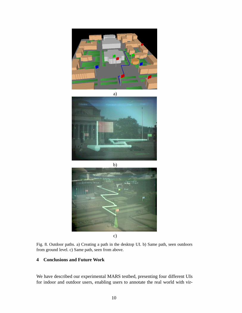
Our four UIs offer many opportunities for indoor/outdoor communication and col-laboration. New virtual objects can be introduced by any UI and, when movedaround, their position is updated in all participating UIs. This can be used, for ex-ample, to highlight points of interest. Figure 8 shows an example of indoor/outdoorinteraction: an indoor user giving guidance to a roaming user by drawing a path onthe virtual model (part a). Parts (b) and (c) shows outdoor views of that path as seenfrom two different perspectives.
9
a)
b)
c)
Fig. 8. Outdoor paths. a) Creating a path in the desktop UI. b) Same path, seen outdoorsfrom ground level. c) Same path, seen from above.
4 Conclusions and Future Work
We have described our experimental MARS testbed, presenting four different UIsfor indoor and outdoor users, enabling users to annotate the real world with vir-
10

tual information and to explore the merged environment. Indoor users can provideguidance to outdoor users by sketching paths or pointing out objects of interest. Anoutdoor user’s position and head orientation can be tracked in the indoor systemand logged in the main database for later review.
There are many directions in which we would like to extend this work. Becausethe indoor augmented reality UI lends itself well to collaborative work, we areintegrating it with our EMMIE multi-user augmented reality system [4]. This willallow us to further explore EMMIE’s support for customized views for displayingprivate information; for example, to allow different indoor users to direct and tracktheir own separate crews of outdoor users. Over the past few months, we havestarted to collaborate with researchers at the Naval Research Lab, with the goalof linking our systems with ones that they are building, to support a collaborativeMARS environment that is distributed across both our campuses.
4.1 Acknowledgements
This work was funded in part by Office of Naval Research Contracts N00014-97-1-0838, N00014-99-1-0249, and N00014-99-1-0394; the Advanced Network &Services National Tele-Immersion Initiative; and gifts from Intel, Microsoft, Mit-subishi, and IBM.
References
[1] R. T. Azuma. A survey of augmented reality.Presence: Teleoperators and VirtualEnvironments, 6(4):355–385, Aug. 1997.
[2] H. Beadle, B. Harper, G. Maguire Jr., and J. Judge. Location aware mobile computing.In Proc. ICT ’97 (IEEE/IEE Int. Conf. on Telecomm.), Melbourne, Australia, 1997.
[3] M. Billinghurst, J. Bowskill, M. Jessop, and J. Morphett. A wearable spatialconferencing space. InProc. ISWC ’98 (Second Int. Symposium on WearableComputers), pages 76–83, 1998.
[4] A. Butz, T. Hollerer, S. Feiner, B. MacIntyre, and C. Beshers. Enveloping users andcomputers in a collaborative 3D augmented reality. InProc. IWAR ’99 (Int. Workshopon Augmented Reality), San Francisco, CA, October 20–21 1999.
[5] S. Feiner, B. MacIntyre, T. H¨ollerer, and A. Webster. A touring machine: Prototyping3D mobile augmented reality systems for exploring the urban environment. InProc.ISWC ’97 (First Int. Symp. on Wearable Computers), pages 74–81, Cambridge, MA,October 13–14 1997.
[6] S. Feiner, B. MacIntyre, and D. Seligmann. Knowledge-based augmented reality.Communications of the ACM, 36(7):52–62, July 1993.
11

[7] S. Feiner and A. Shamash. Hybrid user interfaces: Breeding virtually bigger interfacesfor physically smaller computers. InProc. UIST ’91, pages 9–17. ACM press, 1991.
[8] T. Hollerer, S. Feiner, and J. Pavlik. Situated documentaries: Embedding multimediapresentations in the real world. InProc. ISWC ’99 (Third Int. Symp. on WearableComputers), San Francisco, CA, October 18–19 1999.
[9] B. Jang, J. Kim, H. Kim, and D. Kim. An outdoor augmented reality system for GISapplications. In Y. Ohta and H. Tamura, editors,Mixed Reality, Merging Real andVirtual Worlds, pages 391–399. Ohmsha/Springer, Tokyo/New York, 1999.
[10] S. Long, D. Aust, G. Abowd, and C. Atkenson. Cyberguide: Prototyping context-aware mobile applications. InCHI ’96 Conference Companion, pages 293–294, April1996.
[11] J. Loomis, R. Golledge, and R. Klatzky. Personal guidance system for the visuallyimpaired using GPS, GIS, and VR technologies. InProc. Conf. on Virtual Reality andPersons with Disabilities, Millbrae, CA, June 17–18 1993.
[12] B. MacIntyre and S. Feiner. Language-level support for exploratory programmingof distributed virtual environments. InProc. UIST ’96, pages 83–94, Seattle, WA,November 6–8 1996.
[13] B. MacIntyre and S. Feiner. A distributed 3D graphics library. InComputer Graphics(Proc. ACM SIGGRAPH ’98), Annual Conference Series, pages 361–370, Orlando,FL, July 19–24 1998.
[14] J. Rekimoto and M. Saitoh. Augmented surfaces: A spatially continuous work spacefor hybrid computing environments. InProc. ACM CHI ’99, Pittsburgh, PA, May15–20 1999. ACM Press.
[15] A. Smailagic and R. Martin. Metronaut: A wearable computer with sensing andglobal communication capabilities. InProc. ISWC ’97 (First Int. Symp. on WearableComputers), pages 116–122, Cambridge, MA, October 13–14 1997.
[16] J. Spohrer. WorldBoard—What Comes After the WWW?http://www.worldboard.org/pub/spohrer/wbconcept/default.html, 1997.
[17] Z. Szalavari, E. Eckstein, and M. Gervautz. Collaborative gaming in augmentedreality. InProc. VRST ’98, pages 195–204, Taipei, Taiwan, November 1998.
[18] Z. Szalavari, D. Schmalstieg, A. Fuhrmann, and M. Gervautz. ”Studierstube”: Anenvironment for collaboration in augmented reality.Virtual Reality, 3(1):37–48, 1998.
[19] B. Thomas, V. Demczuk, W. Piekarski, D. Hepworth, and B. Gunther. A wearablecomputer system with augmented reality to support terrestrial navigation. InProc.ISWC ’98 (Second Int. Symp. on Wearable Computers), pages 168–171, Pittsburgh,PA, October 19–20 1998.
12