Embed Size (px)
Citation preview
www.atos.com
Explosion-proof solenoid valveson/off and proportional controls - C UL US certification
Table E125-12/E
E125
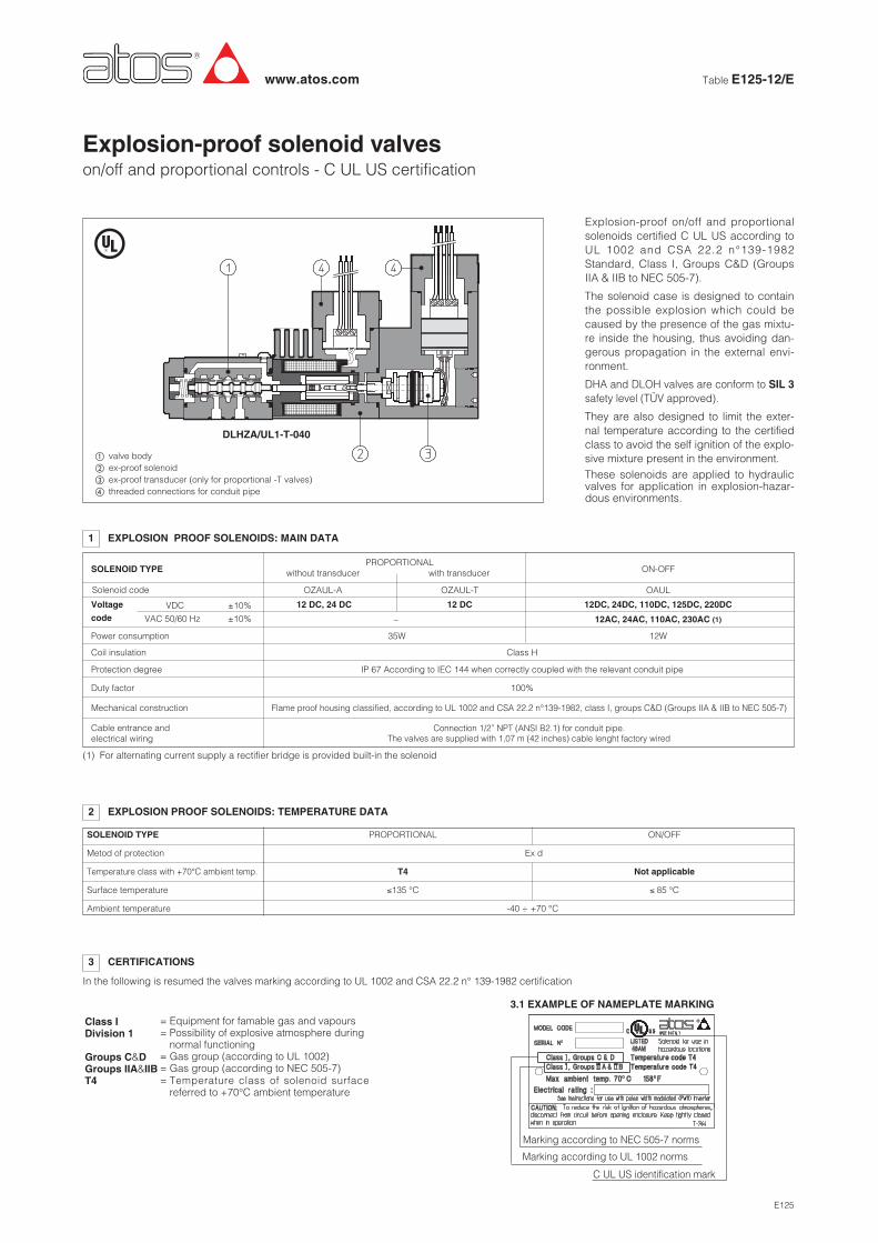
DLHZA/UL1-T-040
� valve body� ex-proof solenoid� ex-proof transducer (only for proportional -T valves)� threaded connections for conduit pipe
2 EXPLOSION PROOF SOLENOIDS: TEMPERATURE DATA
1 EXPLOSION PROOF SOLENOIDS: MAIN DATA
SOLENOID TYPEPROPORTIONAL
ON-OFFwithout transducer with transducer
OZAUL-A OZAUL-T OAULSolenoid code
Power consumption 35W 12W
Coil insulation Class H
Protection degree IP 67 According to IEC 144 when correctly coupled with the relevant conduit pipe
Duty factor 100%
Mechanical construction
Cable entrance and electrical wiring
Flame proof housing classified, according to UL 1002 and CSA 22.2 n°139-1982, class I, groups C&D (Groups IIA & IIB to NEC 505-7)
Connection 1/2” NPT (ANSI B2.1) for conduit pipe.The valves are supplied with 1,07 m (42 inches) cable lenght factory wired
Voltage 12 DC, 24 DC 12 DC 12DC, 24DC, 110DC, 125DC, 220DC
code – 12AC, 24AC, 110AC, 230AC (1)
VDC
VAC 50/60 Hz
3 CERTIFICATIONS
(1) For alternating current supply a rectifier bridge is provided built-in the solenoid
In the following is resumed the valves marking according to UL 1002 and CSA 22.2 n° 139-1982 certification
3.1 EXAMPLE OF NAMEPLATE MARKING
Explosion-proof on/off and proportionalsolenoids certified C UL US according toUL 1002 and CSA 22.2 n°139-1982Standard, Class I, Groups C&D (GroupsIIA & IIB to NEC 505-7).
The solenoid case is designed to containthe possible explosion which could becaused by the presence of the gas mixtu-re inside the housing, thus avoiding dan-gerous propagation in the external envi-ronment.
DHA and DLOH valves are conform to SIL 3safety level (TÜV approved).
They are also designed to limit the exter-nal temperature according to the certifiedclass to avoid the self ignition of the explo-sive mixture present in the environment.These solenoids are applied to hydraulicvalves for application in explosion-hazar-dous environments.
SOLENOID TYPE PROPORTIONAL ON/OFF
Metod of protection Ex d
Temperature class with +70°C ambient temp. T4 Not applicable
Surface temperature ≤135 °C ≤ 85 °C
Ambient temperature -40 ÷ +70 °C
±10%
±10%
C UL US identification mark
Marking according to UL 1002 norms
Marking according to NEC 505-7 norms
= Equipment for famable gas and vapours= Possibility of explosive atmosphere during
normal functioning = Gas group (according to UL 1002)= Gas group (according to NEC 505-7)= Temperature class of solenoid surface
referred to +70°C ambient temperature
Class I Division 1
Groups C&DGroups IIA&IIBT4
Options:A = solenoid at side of port B (for single solenoid valves)O = horizontal cable entranceMV = vertical hand lever (1)WP = prolongued manual override protected by metallic cap
Only for DPHA:/D =Internal drain./E =External pilot pressure./H =Adjustable chokes (meter-out to the pilot chambers of
the main valve)./H9 =Adjustable chokes (meter-in to the pilot chambers of the
main valve)./S = Main spool stroke adjustment (only for DPHA-2, -3).
NPT
DHA = spool type - directDPHA = spool type - piloted
C UL US certificationUL = without cablesUL1 = with 1 m cables lenght, factory wired
Solenoid threated connection:NPT = 1/2” NPT ANSI B2.1 (tapered)
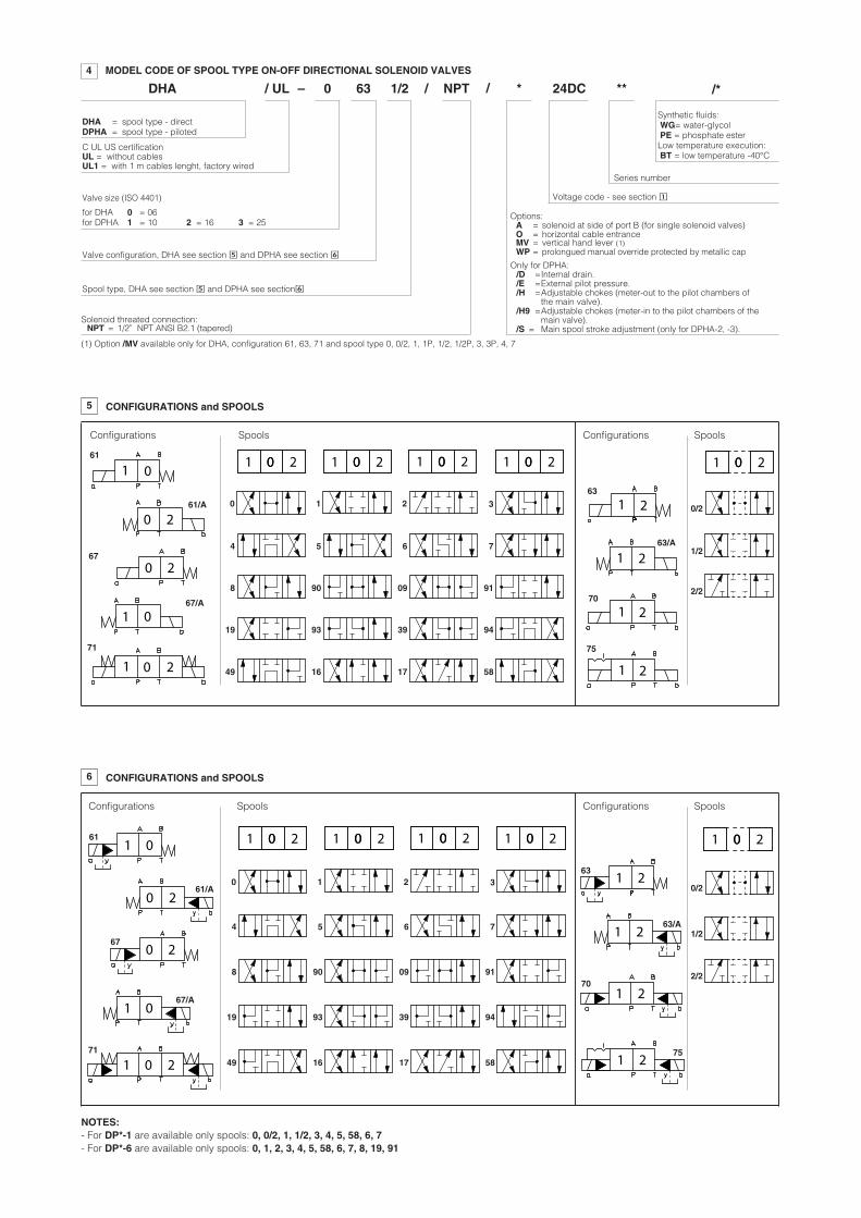
4 MODEL CODE OF SPOOL TYPE ON-OFF DIRECTIONAL SOLENOID VALVES
Valve configuration, DHA see section � and DPHA see section �
Spool type, DHA see section � and DPHA see section�
Synthetic fluids:WG= water-glycolPE = phosphate esterLow temperature execution:BT = low temperature -40°C
Series number
DHA 0–/ UL 63 1/2 24DC ** /*
Valve size (ISO 4401)
for DHA 0 = 06for DPHA 1 = 10 2 = 16 3 = 25
Voltage code - see section �
/ / *
(1) Option /MV available only for DHA, configuration 61, 63, 71 and spool type 0, 0/2, 1, 1P, 1/2, 1/2P, 3, 3P, 4, 7
21
21
0 21
01
71
63
61
75
67/A
63/A
61/A
67
5 CONFIGURATIONS and SPOOLS
0
8
49
1
90
16
2
09
17
3
91
58
4
19
5
93
6
39
7
94
0 2
0 2
01
21
0/2
1/2
2/2
01 0 201 0 201 0 201 0 201 0 2
Configurations Spools Configurations Spools
2170
NOTES:- For DP*-1 are available only spools: 0, 0/2, 1, 1/2, 3, 4, 5, 58, 6, 7- For DP*-6 are available only spools: 0, 1, 2, 3, 4, 5, 58, 6, 7, 8, 19, 91
1 2
1 2
1 21 0 2
1 01 2
0 2
0 2
1 0
71
63
61
75
67/A
63/A
61/A
67
6 CONFIGURATIONS and SPOOLS
0
8
49
1
90
16
2
09
17
3
91
58
4
19
5
93
6
39
7
94
0/2
1/2
2/2
01 0 201 0 201 0 201 0 201 0 2
70
Configurations Spools Configurations Spools
E125
NPT
Directional control valve poppet type, size 06
H = max flow 12 l/minK = max flow 30 l/min
Solenoid threated connection:NPT = 1/2” NPT ANSI B2.1 (tapered)
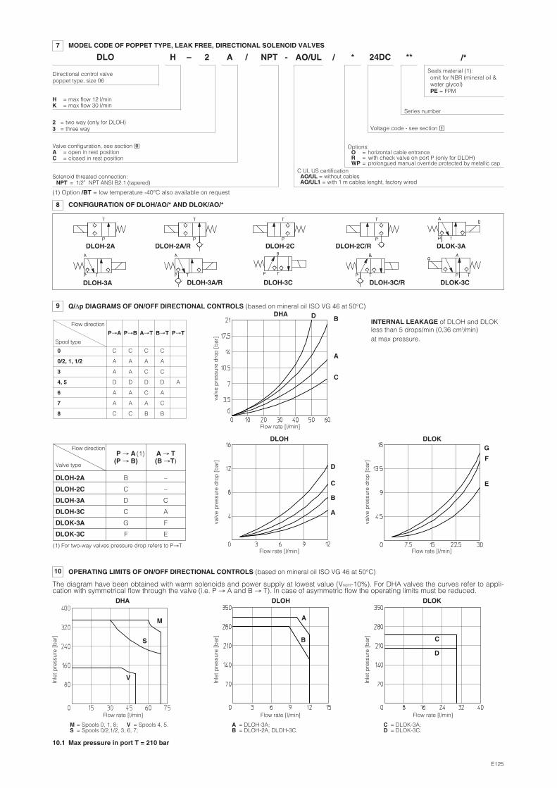
7 MODEL CODE OF POPPET TYPE, LEAK FREE, DIRECTIONAL SOLENOID VALVES
Valve configuration, see section �A = open in rest positionC = closed in rest position
Series number
DLO 2–H A 24DC ** /*
2 = two way (only for DLOH)3 = three way Voltage code - see section �
/ / *- AO/UL
Options:O = horizontal cable entrance R = with check valve on port P (only for DLOH)WP = prolongued manual override protected by metallic cap
C UL US certificationAO/UL = without cablesAO/UL1 = with 1 m cables lenght, factory wired
9 Q/Δp DIAGRAMS OF ON/OFF DIRECTIONAL CONTROLS (based on mineral oil ISO VG 46 at 50°C)
0 C C C C
0/2, 1, 1/2 A A A A
3 A A C C
4, 5 D D D D A
6 A A C A
7 A A A C
8 C C B B
DHA
DLOH DLOK
valv
e p
ress
ure
dro
p [
bar
]
Flow rate [l/min]
D B
A
C
Flow direction
Spool type
P→A P→B A→T B→T P→T
P → A A → T(P → B) (B →T)
Flow rate [l/min] Flow rate [l/min]
valv
e p
ress
ure
dro
p [
bar
]
valv
e p
ress
ure
dro
p [
bar
]
A
D
C
B
G
F
EDLOH-2A B –
DLOH-2C C –
DLOH-3A D C
DLOH-3C C A
DLOK-3A G F
DLOK-3C F E
Flow direction
Valve type
(1)
(1) For two-way valves pressure drop refers to P→T
10 OPERATING LIMITS OF ON/OFF DIRECTIONAL CONTROLS (based on mineral oil ISO VG 46 at 50°C)
The diagram have been obtained with warm solenoids and power supply at lowest value (Vnom-10%). For DHA valves the curves refer to appli-cation with symmetrical flow through the valve (i.e. P → A and B → T). In case of asymmetric flow the operating limits must be reduced.
Flow rate [l/min]
Inle
t pre
ssur
e [b
ar]
V
M
S
DHA
Flow rate [l/min]
Inle
t pre
ssur
e [b
ar]
A
B
DLOH
Flow rate [l/min]
Inle
t pre
ssur
e [b
ar]
D
C
DLOK
M = Spools 0, 1, 8;S = Spools 0/2,1/2, 3, 6, 7;
V = Spools 4, 5. A = DLOH-3A;B = DLOH-2A, DLOH-3C.
C = DLOK-3A;D = DLOK-3C.
INTERNAL LEAKAGE of DLOH and DLOKless than 5 drops/min (0,36 cm3/min) at max pressure.
8 CONFIGURATION OF DLOH/AO/* AND DLOK/AO/*
DLOH-2A DLOH-2A/R DLOH-2C DLOH-2C/R DLOK-3A
DLOH-3A DLOH-3A/R DLOH-3C DLOH-3C/R DLOK-3C
10.1 Max pressure in port T = 210 bar
(1) Option /BT = low temperature -40°C also available on request
Seals material (1):omit for NBR (mineral oil &water glycol)PE = FPM
12
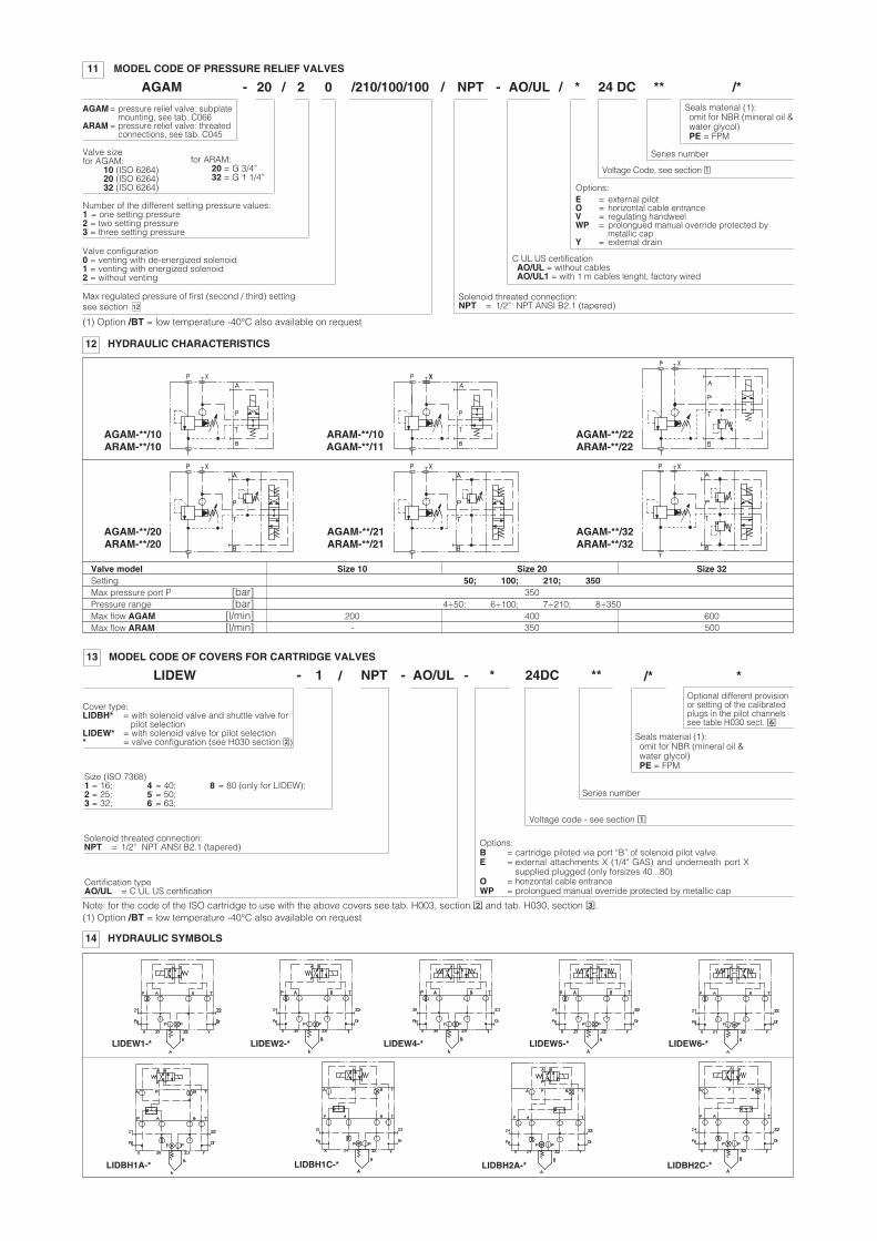
AGAM
AGAM = pressure relief valve: subplatemounting, see tab. C066
ARAM = pressure relief valve: threated connections, see tab. C045
11 MODEL CODE OF PRESSURE RELIEF VALVES
Valve sizefor AGAM:
10 (ISO 6264)20 (ISO 6264)32 (ISO 6264)
for ARAM:20 = G 3/4”32 = G 1 1/4”
20
Valve configuration0 = venting with de-energized solenoid1 = venting with energized solenoid2 = without venting
2 0
Max regulated pressure of first (second / third) setting
NPT 24 DC /*
Series number
**- / AO/UL
Voltage Code, see section �
-
NPT13 MODEL CODE OF COVERS FOR CARTRIDGE VALVES
Series number
LIDEW 1- AO/UL 24DC ** /*
Certification typeAO/UL = C UL US certification
/ -
Solenoid threated connection:NPT = 1/2” NPT ANSI B2.1 (tapered)
Note: for the code of the ISO cartridge to use with the above covers see tab. H003, section � and tab. H030, section �.
Voltage code - see section �
/ / *
Solenoid threated connection:NPT = 1/2” NPT ANSI B2.1 (tapered)
C UL US certificationAO/UL = without cablesAO/UL1 = with 1 m cables lenght, factory wired
Options:E = external pilotO = horizontal cable entranceV = regulating handweelWP = prolongued manual override protected by
metallic capY = external drain
Options:B = cartridge piloted via port “B” of solenoid pilot valveE = external attachments X (1/4" GAS) and underneath port X
supplied plugged (only forsizes 40...80)O = horizontal cable entrance WP = prolongued manual override protected by metallic cap
Size (ISO 7368)1 = 16; 4 = 40; 8 = 80 (only for LIDEW);2 = 25; 5 = 50;3 = 32; 6 = 63;
*Optional different provisionor setting of the calibratedplugs in the pilot channelssee table H030 sect. �
*-
/210/100/100
Number of the different setting pressure values:1 = one setting pressure2 = two setting pressure 3 = three setting pressure
see section
14 HYDRAULIC SYMBOLS
LIDBH1A-*
LIDEW1-* LIDEW2-* LIDEW4-* LIDEW5-* LIDEW6-*
LIDBH1C-* LIDBH2A-* LIDBH2C-*
Cover type:LIDBH* = with solenoid valve and shuttle valve for
pilot selectionLIDEW* = with solenoid valve for pilot selection* = valve configuration (see H030 section �)
12 HYDRAULIC CHARACTERISTICS
AGAM-**/10ARAM-**/10
AGAM-**/20ARAM-**/20
ARAM-**/10AGAM-**/11
AGAM-**/21ARAM-**/21
AGAM-**/22ARAM-**/22
AGAM-**/32ARAM-**/32
Valve model Size 10 Size 20 Size 32Setting 50; 100; 210; 350Max pressure port P [bar] 350Pressure range [bar] 4÷50; 6÷100; 7÷210; 8÷350Max flow AGAM [l/min] 200 400 600Max flow ARAM [l/min] 350 500-
(1) Option /BT = low temperature -40°C also available on request
(1) Option /BT = low temperature -40°C also available on request
Seals material (1):omit for NBR (mineral oil &water glycol)PE = FPM
Seals material (1):omit for NBR (mineral oil &water glycol)PE = FPM
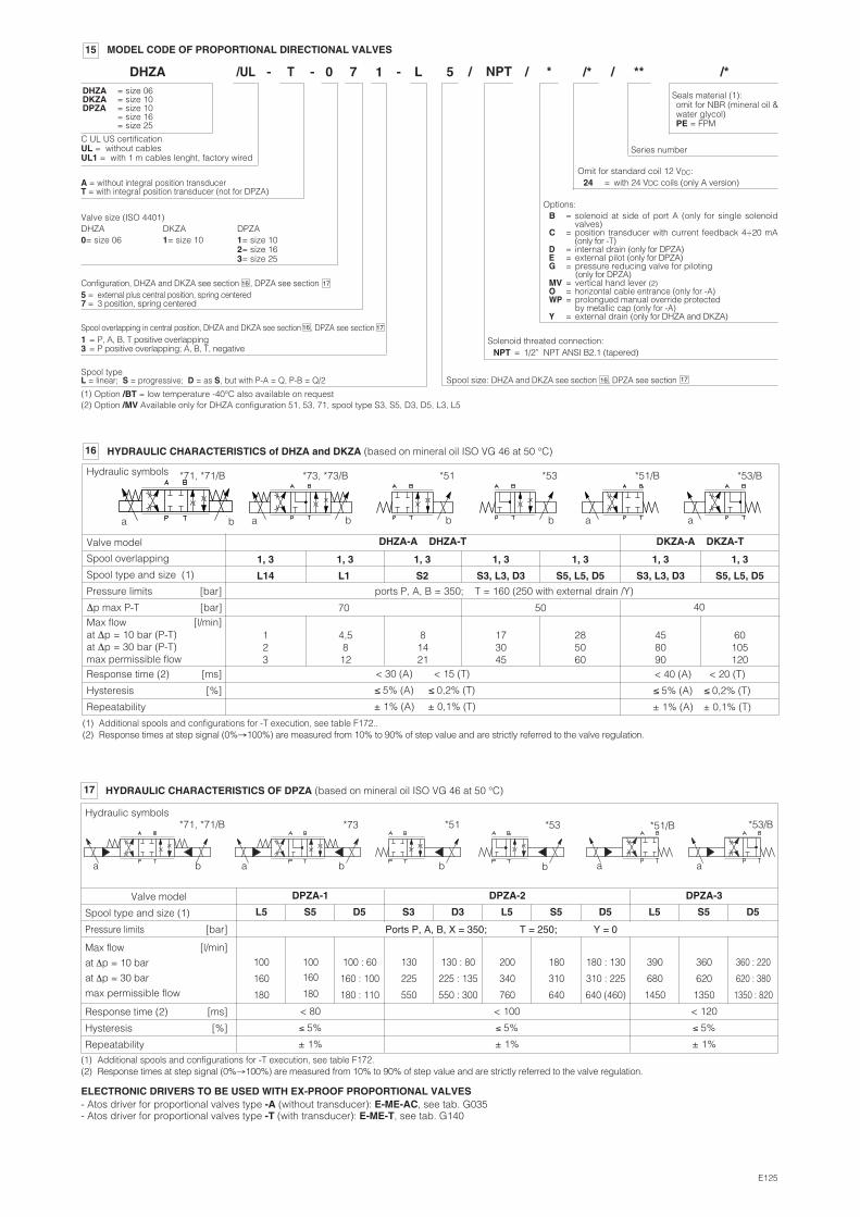
1716Spool overlapping in central position, DHZA and DKZA see section , DPZA see section1 = P, A, B, T positive overlapping3 = P positive overlapping; A, B, T, negative
1716
17
Configuration, DHZA and DKZA see section , DPZA see section5 = external plus central position, spring centered7 = 3 position, spring centered
16
Series number
DHZADHZA = size 06DKZA = size 10DPZA = size 10
= size 16= size 25
A = without integral position transducerT = with integral position transducer (not for DPZA)
Spool typeL = linear; S = progressive; D = as S, but with P-A = Q, P-B = Q/2
/UL T 0 7 - L 5 / ** /*- -
15 MODEL CODE OF PROPORTIONAL DIRECTIONAL VALVES
C UL US certificationUL = without cablesUL1 = with 1 m cables lenght, factory wired
NPT *1
Solenoid threated connection:NPT = 1/2” NPT ANSI B2.1 (tapered)
Options:B = solenoid at side of port A (only for single solenoid
valves)C = position transducer with current feedback 4÷20 mA
(only for -T)D = internal drain (only for DPZA)E = external pilot (only for DPZA)G = pressure reducing valve for piloting
(only for DPZA)MV = vertical hand lever (2)O = horizontal cable entrance (only for -A)WP = prolongued manual override protected
by metallic cap (only for -A)Y = external drain (only for DHZA and DKZA)
/
Spool size: DHZA and DKZA see section , DPZA see section
ELECTRONIC DRIVERS TO BE USED WITH EX-PROOF PROPORTIONAL VALVES- Atos driver for proportional valves type -A (without transducer): E-ME-AC, see tab. G035- Atos driver for proportional valves type -T (with transducer): E-ME-T, see tab. G140
E125
/* /
Omit for standard coil 12 VDC:24 = with 24 VDC coils (only A version)
(1) Option /BT = low temperature -40°C also available on request(2) Option /MV Available only for DHZA configuration 51, 53, 71, spool type S3, S5, D3, D5, L3, L5
Valve size (ISO 4401)DHZA DKZA DPZA0= size 06 1= size 10 1= size 10
2= size 163= size 25
17 HYDRAULIC CHARACTERISTICS OF DPZA (based on mineral oil ISO VG 46 at 50 °C)
Valve model
Spool type and size (1)
Pressure limits [bar]
DPZA-1 DPZA-2
Ports P, A, B, X = 350; T = 250; Y = 0
DPZA-3
Max flow [l/min]
at Δp = 10 bar
at Δp = 30 bar
max permissible flow
Response time (2) [ms]
Hysteresis [%]
Repeatability
100
160
180
100
160
180
100 : 60
160 : 100
180 : 110
130
225
550
130 : 80
225 : 135
550 : 300
200
340
760
180
310
640
180 : 130
310 : 225
640 (460)
390
680
1450
360
620
1350
360 : 220
620 : 380
1350 : 820
S5 D5 S3 D3 L5 S5 D5 L5 S5 D5L5
Hydraulic symbols
< 80
≤ 5%
± 1%
< 100
≤ 5%
± 1%
< 120
≤ 5%
± 1%
*71, *71/B *73 *51 *53
a a b b
*51/B
a
*53/B
ab b
(1) Additional spools and configurations for -T execution, see table F172.(2) Response times at step signal (0%→100%) are measured from 10% to 90% of step value and are strictly referred to the valve regulation.
16 HYDRAULIC CHARACTERISTICS of DHZA and DKZA (based on mineral oil ISO VG 46 at 50 °C)
(1) Additional spools and configurations for -T execution, see table F172..(2) Response times at step signal (0%→100%) are measured from 10% to 90% of step value and are strictly referred to the valve regulation.
Valve model DHZA-A DHZA-T
Spool type and size (1)
Spool overlapping
Max flow [l/min]at Δp = 10 bar (P-T)at Δp = 30 bar (P-T)max permissible flowResponse time (2) [ms]
Hysteresis [%]
Repeatability
123
4,5812
458090
60105120
L14 L1
173045
S3, L3, D3
285060
S5, L5, D5 S3, L3, D3 S5, L5, D5
1, 3 1, 3 1, 3 1, 3 1, 3 1, 3
Hydraulic symbols *71, *71/B *73, *73/B *51 *53 *51/B *53/B
b b b a aaa b
DKZA-A DKZA-T
Pressure limits [bar] ports P, A, B = 350; T = 160 (250 with external drain /Y)
81421
S2
1, 3
< 30 (A)
≤ 5% (A)
± 1% (A)
< 40 (A)
≤ 5% (A)
± 1% (A)
< 20 (T)
≤ 0,2% (T)
± 0,1% (T)
< 15 (T)
≤ 0,2% (T)
± 0,1% (T)
Δp max P-T [bar] 405070
Seals material (1):omit for NBR (mineral oil &water glycol)PE = FPM
19
19
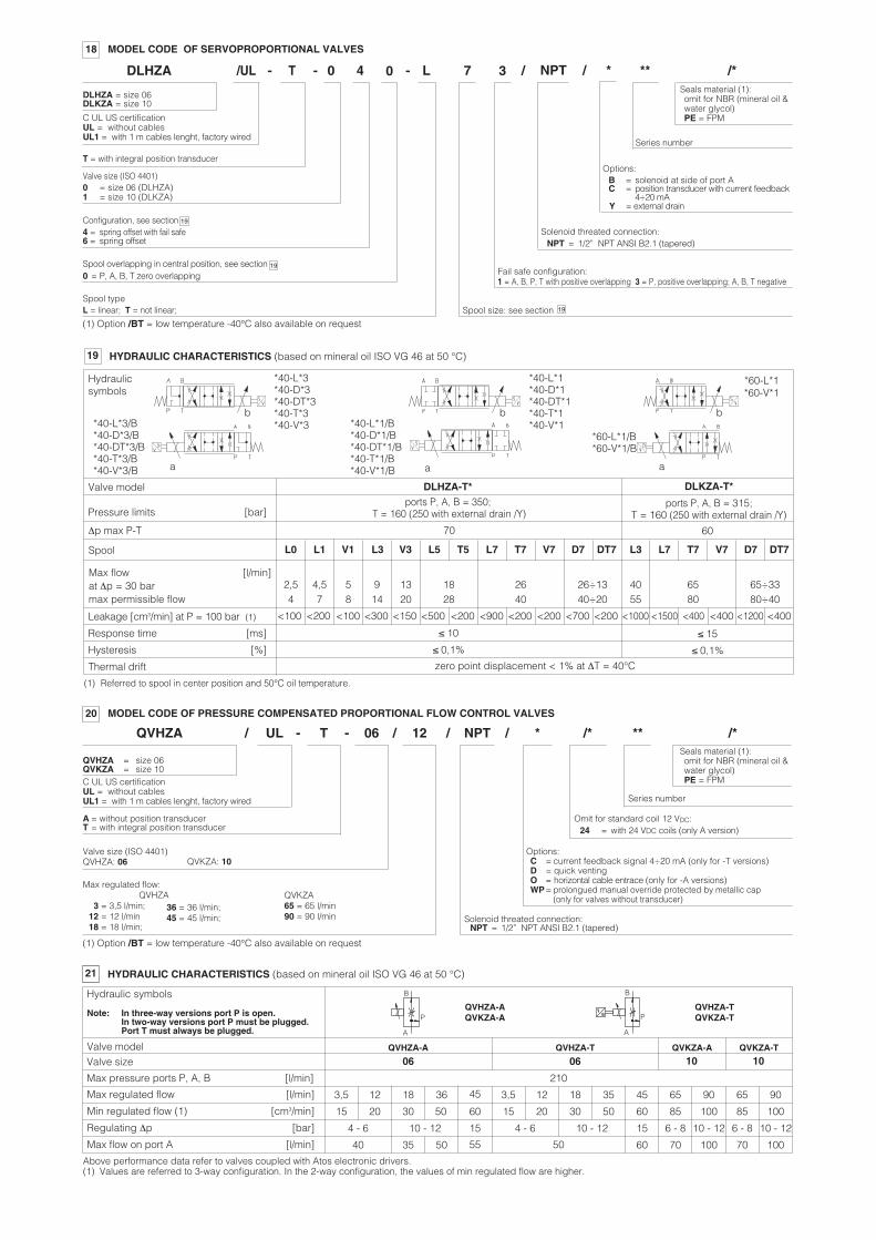
18 MODEL CODE OF SERVOPROPORTIONAL VALVES
DLHZA = size 06DLKZA = size 10
Series number
DLHZA
T = with integral position transducer
Spool typeL = linear; T = not linear; Spool size: see section
/UL T 0 4 - L 7 / ** /*- -
Valve size (ISO 4401)0 = size 06 (DLHZA)1 = size 10 (DLKZA)
C UL US certificationUL = without cablesUL1 = with 1 m cables lenght, factory wired
NPT *0
Solenoid threated connection:NPT = 1/2” NPT ANSI B2.1 (tapered)
Options:B = solenoid at side of port AC = position transducer with current feedback
4÷20 mA Y = external drain
3
Fail safe configuration:1 = A, B, P, T with positive overlapping 3 = P, positive overlapping; A, B, T negative
/
19
Configuration, see section 4 = spring offset with fail safe6 = spring offset
Spool overlapping in central position, see section 0 = P, A, B, T zero overlapping
Options:C = current feedback signal 4÷20 mA (only for -T versions)D = quick ventingO = horizontal cable entrace (only for -A versions)WP= prolongued manual override protected by metallic cap
(only for valves without transducer)
Series number
** /*
Max regulated flow:
3 = 3,5 l/min; 12 = 12 l/min18 = 18 l/min;
QVKZA65 = 65 l/min90 = 90 l/min
12/ / NPT *
20 MODEL CODE OF PRESSURE COMPENSATED PROPORTIONAL FLOW CONTROL VALVES
Solenoid threated connection:NPT = 1/2” NPT ANSI B2.1 (tapered)
QVHZA = size 06QVKZA = size 10
A = without position transducerT = with integral position transducer
QVHZA T 06
Valve size (ISO 4401)QVHZA: 06 QVKZA: 10
UL/ - -
C UL US certificationUL = without cablesUL1 = with 1 m cables lenght, factory wired
/*
36 = 36 l/min;45 = 45 l/min;
QVHZA
/
21 HYDRAULIC CHARACTERISTICS (based on mineral oil ISO VG 46 at 50 °C)
Max regulated flow [l/min]
Min regulated flow (1) [cm3/min]
Regulating Δp [bar]
Max flow on port A [l/min]
Valve model
Note: In three-way versions port P is open.In two-way versions port P must be plugged.Port T must always be plugged.
Hydraulic symbolsQVHZA-AQVKZA-A
QVHZA-A QVHZA-T QVKZA-A QVKZA-T
QVHZA-TQVKZA-T
3,5 12 18 45 12 18 35 45 65 90
15 20 30 50 60 15 20 30 50 60 85 85 100
4 - 6 10 - 12 15 4 - 6 10 - 12 15
60
6 - 8 6 - 8 10 - 12
40 35 50 55 50 70 10070
90
100
10 - 12
100
Above performance data refer to valves coupled with Atos electronic drivers.(1) Values are referred to 3-way configuration. In the 2-way configuration, the values of min regulated flow are higher.
36 3,5 65
Valve size 06 06 10 10
A
P
B
A
P
B
Max pressure ports P, A, B [l/min] 210
Omit for standard coil 12 VDC:24 = with 24 VDC coils (only A version)
(1) Option /BT = low temperature -40°C also available on request
(1) Option /BT = low temperature -40°C also available on request
19 HYDRAULIC CHARACTERISTICS (based on mineral oil ISO VG 46 at 50 °C)
Valve model
Pressure limits [bar]
DLHZA-T*ports P, A, B = 350;
T = 160 (250 with external drain /Y)
DLKZA-T*
ports P, A, B = 315; T = 160 (250 with external drain /Y)
Spool
Leakage [cm3/min] at P = 100 bar (1)
Response time [ms]
Hysteresis [%]
Thermal drift
≤ 10
≤ 0,1%
≤ 15
≤ 0,1%
Hydraulicsymbols
*60-L*1*60-V*1
b b
*60-L*1/B*60-V*1/B
a a a
b
zero point displacement < 1% at ΔT = 40°C
L0
Max flow [l/min]at Δp = 30 barmax permissible flow
2,54
L1 V1 L3 V3 L5 T5 L7 T7 V7 D7 DT7 L3 L7 T7 V7 D7 DT7
4,57
58
914
1320
1828
2640
26÷1340÷20
4055
6580
65÷3380÷40
<200 <300 <500 <200 <900 <200 <1000 <1500 <400<100 <100 <150 <200 <200<700 <1200<400 <400
*40-L*3/B*40-D*3/B*40-DT*3/B*40-T*3/B*40-V*3/B
*40-L*1/B*40-D*1/B*40-DT*1/B*40-T*1/B*40-V*1/B
*40-L*3*40-D*3*40-DT*3*40-T*3*40-V*3
*40-L*1*40-D*1*40-DT*1*40-T*1*40-V*1
(1) Referred to spool in center position and 50°C oil temperature.
Δp max P-T 70 60
Seals material (1):omit for NBR (mineral oil &water glycol)PE = FPM
Seals material (1):omit for NBR (mineral oil &water glycol)PE = FPM
25Max regulated pressure:see section
25Valve size:see section for size code
23
23
Max regulated pressure:see section
Valve size:see section for size code
E125
250
Series number
NPT/ ** /*
Options:E = external pilot (only for AGMZA)O = horizontal cable entraceP = with integral mechanical pressure limiter (only for LI*ZA)Y = external drain (only for AGMZA)
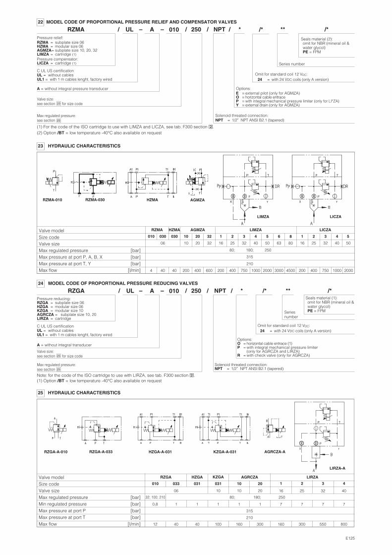
*22 MODEL CODE OF PROPORTIONAL PRESSURE RELIEF AND COMPENSATOR VALVES
Solenoid threated connection:NPT = 1/2” NPT ANSI B2.1 (tapered)
Pressure relief:RZMA = subplate size 06HZMA = modular size 06AGMZA= subplate size 10, 20, 32LIMZA = cartridge (1)Pressure compensator:LICZA = cartridge (1)
A = without integral pressure transducer
C UL US certificationUL = without cablesUL1 = with 1 m cables lenght, factory wired
RZMA AUL/ 010 /– –
250
Seriesnumber
NPT/ ** /**24 MODEL CODE OF PROPORTIONAL PRESSURE REDUCING VALVES
Solenoid threated connection:NPT = 1/2” NPT ANSI B2.1 (tapered)
Pressure reducing:RZGA = subplate size 06HZGA = modular size 06KZGA = modular size 10AGRCZA = subplate size 10, 20LIRZA = cartridge
A = without integral transducer
C UL US certificationUL = without cablesUL1 = with 1 m cables lenght, factory wired
RZGA AUL/ 010 /– –
/*
Options:O = horizontal cable entrace (1)P = with integral mechanical pressure limiter
(only for AGRCZA and LIRZA)R = with check valve (only for AGRCZA)
/*
(1) For the code of the ISO cartridge to use with LIMZA and LICZA, see tab. F300 section �.
Note: for the code of the ISO cartridge to use with LIRZA, see tab. F300 section �.
/
/
Omit for standard coil 12 VDC:24 = with 24 VDC coils (only A version)
Omit for standard coil 12 VDC:24 = with 24 VDC coils (only A version)
(2) Option /BT = low temperature -40°C also available on request
(1) Option /BT = low temperature -40°C also available on request
23 HYDRAULIC CHARACTERISTICS
RZMA-010 HZMA
LIMZA LICZA
RZMA-030 AGMZA
Valve modelSize codeValve sizeMax regulated pressure [bar]Max pressure at port P, A, B, X [bar]Max pressure at port T, Y [bar]Max flow [l/min]
RZMA HZMA AGMZA LIMZA LICZA
010 030 030 10 20 32 1 2 3 4 5 6 1 2 3 4 5
80; 180; 250
315
210
4 40 40 200 400 600 200 400 750 1000 2000 3000 200 400 750 1000 2000
06 10 20 32 16 25 32 40 50 63 16 25 32 40 50
4500
8
80
25 HYDRAULIC CHARACTERISTICS
RZGA-A-010 KZGA-A-031 AGRCZA-A
LIRZA-A
RZGA-A-033 HZGA-A-031
Valve modelSize codeValve sizeMax regulated pressure [bar]Min regulated pressure [bar]Max pressure at port P [bar]Max pressure at port T [bar]Max flow [l/min]
RZGA HZGA KZGA AGRCZA LIRZA
010 033 031 10 20
80; 180; 250
315
0,8
031
32; 100; 210
1 1 1 11 7 77
210
12 40 40 160 300100 300 550
06 10 2010 25 3216
321
160
7
800
40
4
Seals material (2):omit for NBR (mineral oil &water glycol)PE = FPM
Seals material (1):omit for NBR (mineral oil &water glycol)PE = FPM
11/12
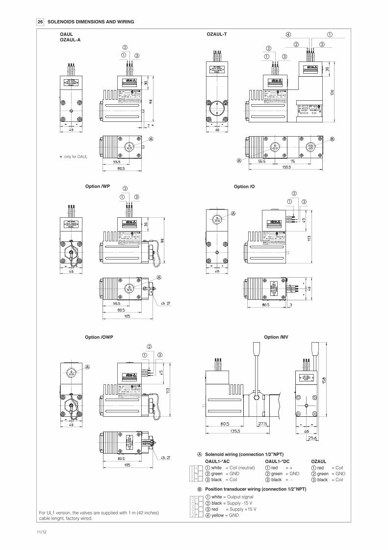
OAULOZAUL-A
OZAUL-T
Option /WP
�
26 SOLENOIDS DIMENSIONS AND WIRING
Option /OWP
Option /O
�
�
�
�
�
�
�
For UL1 version, the valves are supplied with 1 m (42 inches)cable lenght, factory wired.
� �
�
� �
�
� �
�
� �
�
� white = Coil (neutral)� green = GND� black = Coil
OAUL1-*AC
Position transducer wiring (connection 1/2”NPT)
� white = Output signal� black = Supply -15 V� red = Supply +15 V� yellow = GND
�
� red = +� green = GND� black = -
OAUL1-*DC
Solenoid wiring (connection 1/2”NPT)
� red = Coil� green = GND� black = Coil
OZAUL
Option /MV
*
* only for OAUL