Embed Size (px)
Citation preview
Ex
plo
sio
n p
rote
cte
d
with
fix
ed a
nd w
ith a
dju
stable
dis
pla
cem
ent
acc
ord
ing to D
irect
ive 9
4/9
/EC
Hyd
rau
lic
Mo
tors
08
Quality Products for Mechanical
& Fluid Power
11
DÜSTERLOH Fluidtechnik GmbH * Im Vogelsang 105 * 45527 Hattingen * +49 / (0) 2324 / 709-0 * Fax +49 / (0) 2324 / 709-110Changes reserved!
Assembly and Operating Instructions
RM1-001E / ExPage 2Edition 2010.01/01
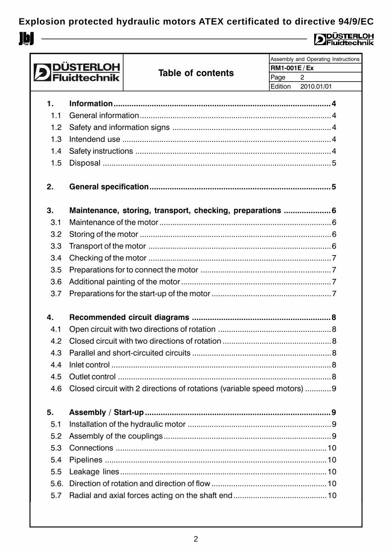
1. Information.................................................................................................4
1.1 General information........................................................................................4
1.2 Safety and information signs .........................................................................4
1.3 Intendend use ................................................................................................4
1.4 Safety instructions ..........................................................................................4
1.5 Disposal .........................................................................................................5
2. General specification.................................................................................5
3. Maintenance, storing, transport, checking, preparations .....................6
3.1 Maintenance of the motor ...............................................................................6
3.2 Storing of the motor ........................................................................................6
3.3 Transport of the motor ....................................................................................6
3.4 Checking of the motor ....................................................................................7
3.5 Preparations for to connect the motor ............................................................7
3.6 Additional painting of the motor .....................................................................7
3.7 Preparations for the start-up of the motor .......................................................7
4. Recommended circuit diagrams ..............................................................8
4.1 Open circuit with two directions of rotation ....................................................8
4.2 Closed circuit with two directions of rotation ..................................................8
4.3 Parallel and short-circuited circuits ................................................................8
4.4 Inlet control .....................................................................................................8
4.5 Outlet control ..................................................................................................8
4.6 Closed circuit with 2 directions of rotations (variable speed motors) ............9
5. Assembly / Start-up ...................................................................................9
5.1 Installation of the hydraulic motor ..................................................................9
5.2 Assembly of the couplings .............................................................................9
5.3 Connections .................................................................................................10
5.4 Pipelines ......................................................................................................10
5.5 Leakage lines ...............................................................................................10
5.6. Direction of rotation and direction of flow .....................................................10
5.7 Radial and axial forces acting on the shaft end...........................................10
Table of contents
Explosion protected hydraulic motors ATEX certificated to directive 94/9/EC
2
DÜSTERLOH Fluidtechnik GmbH * Im Vogelsang 105 * 45527 Hattingen * +49 / (0) 2324 / 709-0 * Fax +49 / (0) 2324 / 709-110Changes reserved!
Assembly and Operating Instructions
RM1-001E / ExPage 3Edition 2010.01/01
Table of contents
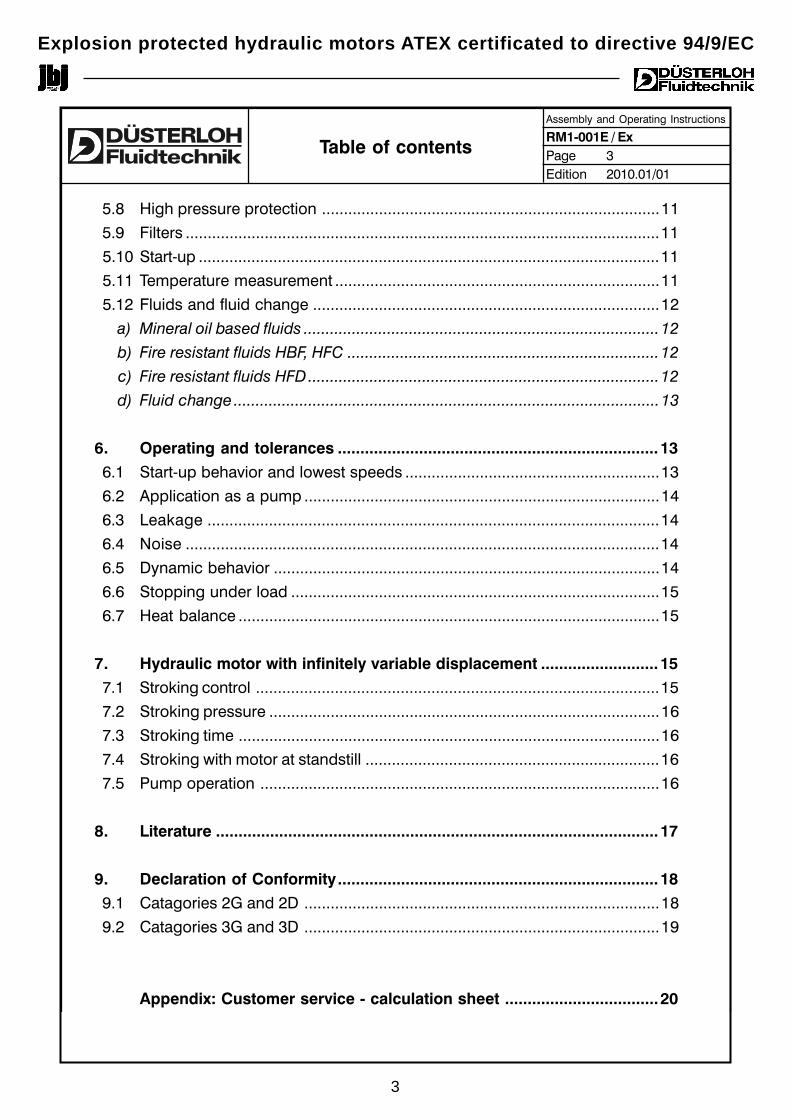
5.8 High pressure protection .............................................................................11
5.9 Filters ............................................................................................................11
5.10 Start-up .........................................................................................................11
5.11 Temperature measurement ..........................................................................11
5.12 Fluids and fluid change ...............................................................................12
a) Mineral oil based fluids .................................................................................12
b) Fire resistant fluids HBF, HFC .......................................................................12
c) Fire resistant fluids HFD................................................................................12
d) Fluid change .................................................................................................13
6. Operating and tolerances .......................................................................13
6.1 Start-up behavior and lowest speeds ..........................................................13
6.2 Application as a pump .................................................................................14
6.3 Leakage .......................................................................................................14
6.4 Noise ............................................................................................................14
6.5 Dynamic behavior ........................................................................................14
6.6 Stopping under load ....................................................................................15
6.7 Heat balance ................................................................................................15
7. Hydraulic motor with infinitely variable displacement ..........................15
7.1 Stroking control ............................................................................................15
7.2 Stroking pressure .........................................................................................16
7.3 Stroking time ................................................................................................16
7.4 Stroking with motor at standstill ...................................................................16
7.5 Pump operation ...........................................................................................16
8. Literature ..................................................................................................17
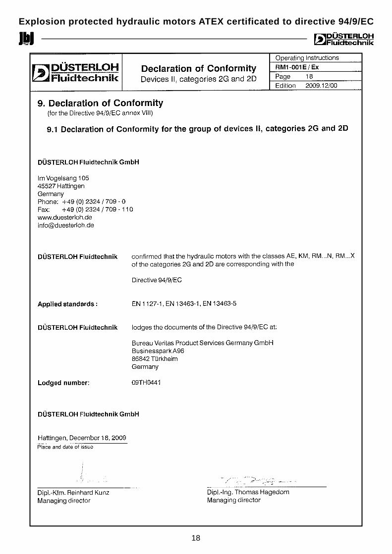
9. Declaration of Conformity.......................................................................18
9.1 Catagories 2G and 2D .................................................................................18
9.2 Catagories 3G and 3D .................................................................................19
Appendix: Customer service - calculation sheet ..................................20
Explosion protected hydraulic motors ATEX certificated to directive 94/9/EC
3
DÜSTERLOH Fluidtechnik GmbH * Im Vogelsang 105 * 45527 Hattingen * +49 / (0) 2324 / 709-0 * Fax +49 / (0) 2324 / 709-110Changes reserved!
Assembly and Operating Instructions
RM1-001E / ExPage 4Edition 2010.01/01
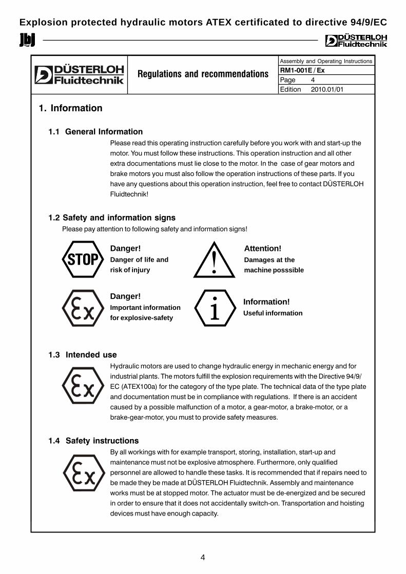
1. Information
1.1 General InformationPlease read this operating instruction carefully before you work with and start-up the
motor. You must follow these instructions. This operation instruction and all other
extra documentations must lie close to the motor. In the case of gear motors and
brake motors you must also follow the operation instructions of these parts. If you
have any questions about this operation instruction, feel free to contact DÜSTERLOH
Fluidtechnik!
1.2 Safety and information signsPlease pay attention to following safety and information signs!
1.3 Intended useHydraulic motors are used to change hydraulic energy in mechanic energy and for
industrial plants. The motors fulfill the explosion requirements with the Directive 94/9/
EC (ATEX100a) for the category of the type plate. The technical data of the type plate
and documentation must be in compliance with regulations. If there is an accident
caused by a possible malfunction of a motor, a gear-motor, a brake-motor, or a
brake-gear-motor, you must to provide safety measures.
1.4 Safety instructionsBy all workings with for example transport, storing, installation, start-up and
maintenance must not be explosive atmosphere. Furthermore, only qualified
personnel are allowed to handle these tasks. It is recommended that if repairs need to
be made they be made at DÜSTERLOH Fluidtechnik. Assembly and maintenance
works must be at stopped motor. The actuator must be de-energized and be secured
in order to ensure that it does not accidentally switch-on. Transportation and hoisting
devices must have enough capacity.
Danger!Danger of life andrisk of injury
Attention!Damages at themachine posssible
Danger!Important informationfor explosive-safety
Information!Useful information
STOP
Regulations and recommendations
!
i
Explosion protected hydraulic motors ATEX certificated to directive 94/9/EC
4
DÜSTERLOH Fluidtechnik GmbH * Im Vogelsang 105 * 45527 Hattingen * +49 / (0) 2324 / 709-0 * Fax +49 / (0) 2324 / 709-110Changes reserved!
Assembly and Operating Instructions
RM1-001E / ExPage 5Edition 2010.01/01
Regulations and recommendations
STOP
Motor parts: Material:
Crankshaft, wobble shaft, bearing, gudgeon pin, screws, spring, Steel
polygon ring, piston (AE, KM, RM..N), control rings, eccentric
Motor case, bearing cover, cylinder cover, control cover, Cast iron
piston (RM..X), engine cover
Conecting rod Bronze
Radial shat seal rings Elastomer with steel
O-rings, parbak-rings, sealing plug Elastomer
Please consider all safety signs also these ones which are in the following chapters of
this operating instruction. Furthermore it must be comply with all national and other
regulations about the safety and accident prevention. Pay attention that with incorrect
installation, incorrect using, wrong handling, disregarding of safety signs, illegal
removing and structural changes from the motor can happen serious person injuries
and property damages.
1.5 DisposalNotice the local regulations about appropriate means of disposal. In particular the proper way to
collect and dispose of lubricants.
2. General specification
DUESTERLOH hydraulic motors are radial piston motors with internally supported pistons and axial
piston motors in wobble plate design. These produce torque through the pressure ring or connecting
rod which operates directly on the eccentric of the drive shaft, respectively on the wobble plate. By
the axial piston motors are the pistons axial in the engine cover and operate directly at the wobble
washer and produce the torque.
The oil distribution, the piston and pressure ring assembly or the piston and connecting rod assembly
are hydrostatically balanced, a feature which gives good starting characteristics with full torque over
the whole speed range with minimal variations. Excellent overall efficiency is guaranteed with low
noise levels.
The low inertia permits rapid alteration in speed and direction of rotation. DUESTERLOH hydraulic
motors have proved their suitability in control circuits with predetermined shaft speed, speed
alteration, torque limiting and alteration and other values. Most of the motors can be supplied with a
second shaft.
Explosion protected hydraulic motors ATEX certificated to directive 94/9/EC
5
DÜSTERLOH Fluidtechnik GmbH * Im Vogelsang 105 * 45527 Hattingen * +49 / (0) 2324 / 709-0 * Fax +49 / (0) 2324 / 709-110Changes reserved!
Assembly and Operating Instructions
RM1-001E / ExPage 6Edition 2010.01/01
Regulations and recommendations
The Motors can be operated in open or closed circuits and also as pumps with a suitable feed.
DUESTERLOH hydraulic motors have been designed for and operated successfully for years with fire-
resistant fluids (see 5.12).
The design of the eccentric and its bearings was based on high radial and axial load factors for the
drive shaft.
DUESTERLOH can also supply hydraulic motors with infinitely variable displacement.
3. Maintenance, storing, transport, checking, preparations
3.1 Maintenance of the motorDUESTERLOH hydraulic motors are maintenance free and are lubricated by their operating fluids.
Refer to specific instructions regarding pressure medium and filter change.
3.2 Storing of the motorAll ports on new motors are closed with plastic plugs. Internal parts are covered with hydraulic oil after
the test run, the external part of the shaft and the connecting port flange are protected by corrosion-
resistant oil. In this condition the motor can be stored in a dry place for about 6 months.
Consider the following points for storing:
• Storing in installation position and in not-fall position
• Bare metal hast to be with oil for protection
• Storing in dry room
• Temperature without high fluctuations between -5°C and +50°C
• Relative humidity less than 60 %
• No directly insulation
• No aggressive or corrosive substances in vicinity
(contaminated air, ozone, gas, solvent, acid, lyes, salts, radioactivity, etc. )
• No shock and vibrations
• If stored for longer periods, the motors must be filled completely with emulsifying hydraulic oil
type H-LPD and all openings have to be plugged or flanged oil-tight. After a maximum storing
time of 12 months, the hydraulic oil must be changed completely and the shaft rotated
approximately 10 times by hand.
3.3 Transport of the motorThe motor shafts have either a threaded centre hole (form DS with DIN 332) suitable
for fitting a ring bolt (DIN 580), or three metrical threads at the front side of the shaft.
All motors can be transported by crane hook or other means in this way.i
Explosion protected hydraulic motors ATEX certificated to directive 94/9/EC
6
DÜSTERLOH Fluidtechnik GmbH * Im Vogelsang 105 * 45527 Hattingen * +49 / (0) 2324 / 709-0 * Fax +49 / (0) 2324 / 709-110Changes reserved!
Assembly and Operating Instructions
RM1-001E / ExPage 7Edition 2010.01/01
3.4 Checking of the motorThe actuator hast to be checked and is just allowed to montage if there is:
• no damage for example; from the storing or transport. In particular has to bechecked the radial shaft seal ring, sealing plug and cover
• no oil leakage• no corrosion or other seeing from improperly storing• no packaging materials at the motor
3.5 Preparations for to connect the motorIt has to keep in mind that at the motor built actuator parts must be ATEX-
conform like gears, brakes, couplings, pulleys etc..
By mounting of the motor must surely not be any explosive atmosphere.
Drive and output elements must have contact protection, like pulleys, couplings
and chains.
If the wrong turn direction makes damages or dangers, then has to figure out with a
test run the correct turn direction of the output shaft.
Make sure that there are not and will not be any aggressive and corrosive
substances. In case of doubt, contact DÜSTERLOH Fluidtechnik for to take any
action that is appropriate.
The flange where the motor gets screwed has to have low vibrations, torsion-resistant
and plane (planarity < 0,2mm). Dirty screw-on surfaces of the motor or flange has to
get cleaned.
3.6 Additional painting of the motorIn the case of additional painting of the motor, the motor must be still clean of color
and solvent the radial shaft seal ring, rubber elements, motor coupling elements and
type label. The complete thickness of the painting has to be maximal 0,2 mm with the
categories II2G/II3G.
3.7 Preparations for the start-up of the motorBefore the start-up of the motor, it must be filled with operative fluid at the leakage
port. It is also possible to let the motor work in unloaded condition (in low operating
pressure) as long as the motor case is full.
The hydraulic system must be vented often. While working the motor, with smallest
speed is the proportion air in the motor very important for the uniformity rate.
The best ventilation is to let the motor run at high speed for a few minutes with the
stub shaft down.
STOP
Regulations and recommendations
!
Explosion protected hydraulic motors ATEX certificated to directive 94/9/EC
7
DÜSTERLOH Fluidtechnik GmbH * Im Vogelsang 105 * 45527 Hattingen * +49 / (0) 2324 / 709-0 * Fax +49 / (0) 2324 / 709-110Changes reserved!
Assembly and Operating Instructions
RM1-001E / ExPage 8Edition 2010.01/01
Regulations and recommendations
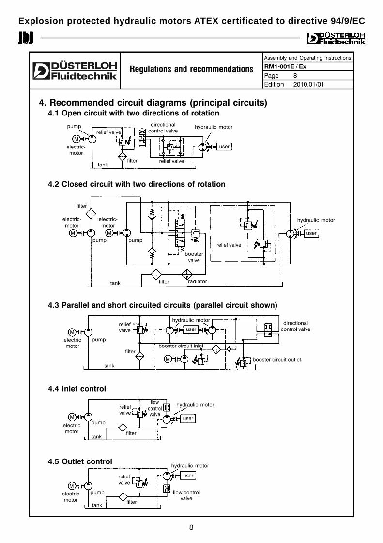
4. Recommended circuit diagrams (principal circuits)4.1 Open circuit with two directions of rotation
4.2 Closed circuit with two directions of rotation
4.3 Parallel and short circuited circuits (parallel circuit shown)
4.4 Inlet control
4.5 Outlet control
relief valve
directionalcontrol valve
user
filtertank
electric-motor
hydraulic motorpump
relief valve
user
filter
tank
electric-motor
hydraulic motor
pump
M
M M
M
pump
filter radiator
reliefvalve
directionalcontrol valveuser
filter
tank
electricmotor
hydraulic motor
pump
M
flowcontrolvalve
user
filtertank
electricmotor
hydraulic motor
pump
booster circuit outlet
booster circuit inlet
user
filtertank
hydraulic motor
pump
M
reliefvalve
flow controlvalve
M
relief valve
electric-motor
boostervalve
reliefvalve
electricmotor
Explosion protected hydraulic motors ATEX certificated to directive 94/9/EC
8
DÜSTERLOH Fluidtechnik GmbH * Im Vogelsang 105 * 45527 Hattingen * +49 / (0) 2324 / 709-0 * Fax +49 / (0) 2324 / 709-110Changes reserved!
Assembly and Operating Instructions
RM1-001E / ExPage 9Edition 2010.01/01
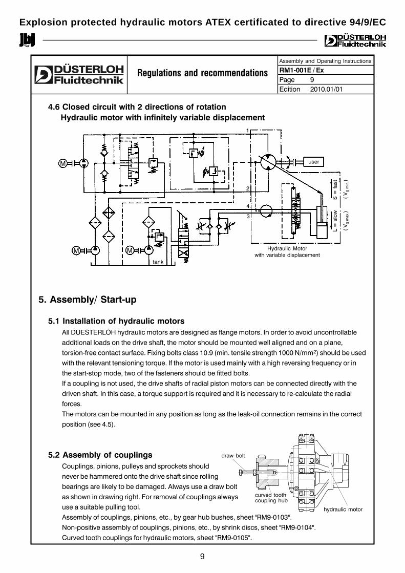
4.6 Closed circuit with 2 directions of rotation Hydraulic motor with infinitely variable displacement
5. Assembly/ Start-up
5.1 Installation of hydraulic motorsAll DUESTERLOH hydraulic motors are designed as flange motors. In order to avoid uncontrollable
additional loads on the drive shaft, the motor should be mounted well aligned and on a plane,
torsion-free contact surface. Fixing bolts class 10.9 (min. tensile strength 1000 N/mm2) should be used
with the relevant tensioning torque. If the motor is used mainly with a high reversing frequency or in
the start-stop mode, two of the fasteners should be fitted bolts.
If a coupling is not used, the drive shafts of radial piston motors can be connected directly with the
driven shaft. In this case, a torque support is required and it is necessary to re-calculate the radial
forces.
The motors can be mounted in any position as long as the leak-oil connection remains in the correct
position (see 4.5).
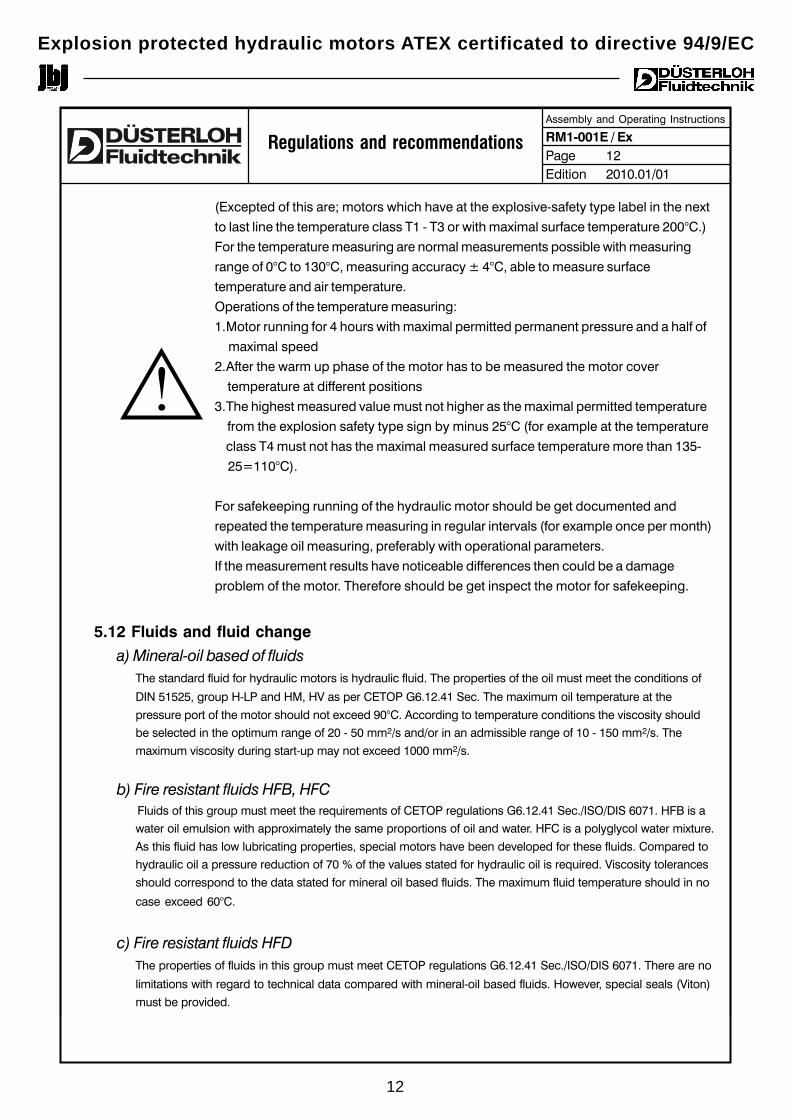
5.2 Assembly of couplingsCouplings, pinions, pulleys and sprockets should
never be hammered onto the drive shaft since rolling
bearings are likely to be damaged. Always use a draw bolt
as shown in drawing right. For removal of couplings always
use a suitable pulling tool.
Assembly of couplings, pinions, etc., by gear hub bushes, sheet "RM9-0103".
Non-positive assembly of couplings, pinions, etc., by shrink discs, sheet "RM9-0104".
Curved tooth couplings for hydraulic motors, sheet "RM9-0105".
Regulations and recommendations
user
Hydraulic Motorwith variable displacement
tank
MM
M
1
2
4
3
L =
slo
wS
= fa
st
( V
g m
ax )
( V
g m
in )
hydraulic motor
curved toothcoupling hub
draw bolt
Explosion protected hydraulic motors ATEX certificated to directive 94/9/EC
9
DÜSTERLOH Fluidtechnik GmbH * Im Vogelsang 105 * 45527 Hattingen * +49 / (0) 2324 / 709-0 * Fax +49 / (0) 2324 / 709-110Changes reserved!
Assembly and Operating Instructions
RM1-001E / ExPage 10Edition 2010.01/01
Regulations and recommendations
5.3 ConnectionsThreaded connections are used on smaller hydraulic motors and SAE-flange connections on larger sizes.
Commercial fittings are required for piping up threaded connections, for flange connections SAE-flanges
have to be used in conjunction with welded piping and compression fittings. Refer to HM1-015E (Page 20
for RM 250X - RM 500X, Page 21 for RM 710X - RM 900X) and HM1-013E (Page 21 for RM 1000X - RM
5000X) for flanges.
5.4 PipelinesIf there is any movement between motors and pipelines, then use flexible connections. Be careful to
observe maker's recommendations. Rigid pipes should be carefully set and not forced when fitting to
motors. Where possible cut and bend pipes cold and remove frazing. Hot bent and welded pipes
should be cleaned mechanically to remove scale, weld spatter and slag and then pickled, neutralized,
water washed and air dried; coat with mineral oil and plug ends until ready to use.
Long lengths of pipe should be securely fastened at 1 meter intervals and air vents provided at the
highest points in the pipe work system. Where compression fittings are used, make sure that they are
fitted to maker's instructions and that they are accessible for maintenance purposes.
Pipe sizes, both rigid and flexible should be based on fluid used, maximum operating pressures,
acceptable fluid velocities and/or flow resistance.
5.5 Leakage linesLeakage lines have to be pressure-less (maximum 1 - 2 bar measured at the hydraulic motor), be
separated from the return line and laid in such a way that the motor housing is always full.
a) Motor fitted with horizontal shaft position:
Use the leakage port above the shaft centre line.
b) Motor fitted with vertical shaft position (downward):
Use the leakage port which is in the highest position.
c) Motor fitted with vertical shaft position (upward):
Use the leakage port which is in the highest position.
Refer to instructions regarding different motor types as per catalogs HM1-014 (KM 11 - RM 250N),
HM1-015 250X - RM 900X, HM1-013 (RM 1000X - RM 5000X)).
5.6 Direction of rotation and direction of flowRotation and flow are shown by arrows in the motor specifications. A change of motor rotation is
achieved by exchanging return and inlet lines.
5.7 Radial and axial forces acting on the shaft endDue to the large radial rolling bearings, the drive shafts of DUESTERLOH radial piston motors can
accommodate considerable radial and axial loads. This constitutes savings in respect of intermediate
Explosion protected hydraulic motors ATEX certificated to directive 94/9/EC
10
DÜSTERLOH Fluidtechnik GmbH * Im Vogelsang 105 * 45527 Hattingen * +49 / (0) 2324 / 709-0 * Fax +49 / (0) 2324 / 709-110Changes reserved!
Assembly and Operating Instructions
RM1-001E / ExPage 11Edition 2010.01/01
Regulations and recommendations
bearings for pinions, pulleys, sprockets etc.. The nominal bearing life of taper roller bearings, based on
the function of radial force and the position of the point where this force is applied, can be taken from the
nomograms shown on the data sheets of individual motors. The manufacturer must be consulted
regarding the bearing life resulting from axial and/or the combination of radial and axial forces. Radial
piston motors with hollow shafts and motors with variable volumetric displacement allow less radial forces
as motors of other designs.
5.8 High pressure protectionTo protect hydraulic motors against unacceptable pressure peaks, relief valves should be installed.
Generally these valves should be capable of relieving maximum flow without pressure increase.
5.9 FiltersCleanliness and good filtration are an absolute must for hydraulic systems to minimize wear and eliminate
operating faults. As finer the filter is as longer is the life of the motor.
Filters should be cleaned and exchanged regularly.
The following filter gauges are recommended:
Main flow filter 10 - 25 μm
Filter in inlet line 10 - 25 μm
Leakage filter about ca. 25 μm
Bypass filter 1 - 10 μm
Pump suction filter 50 - 200 μm
(generally to be avoided because of risk of cavitation observe
recommendations of pump manufacturers)
Oil filter strainer 100 - 500 μm
5.10 Start-upDÜSTERLOH hydraulic motors are long life motors. This implies a running-in of the motors.
Start-up/ running-in of the hydraulic motors:
0 - 15 min: maximum pressure 100 bar, maximum speed 1/3 nmax
above 15 min: gradually increase pressure and speed to operating values.
An optimal motor running will be after a running-in of about 30 hours.
5.11 Temperature measurementATEX temperature class (maximal surface temperature) implies correct installation
conditions. Just a few changes of installation conditions can affect the motor
temperature.
Therefore must be measured the surface temperature at the motor while start-up
with maximal permitted continuous output.
Explosion protected hydraulic motors ATEX certificated to directive 94/9/EC
11
DÜSTERLOH Fluidtechnik GmbH * Im Vogelsang 105 * 45527 Hattingen * +49 / (0) 2324 / 709-0 * Fax +49 / (0) 2324 / 709-110Changes reserved!
Assembly and Operating Instructions
RM1-001E / ExPage 12Edition 2010.01/01
Regulations and recommendations
(Excepted of this are; motors which have at the explosive-safety type label in the next
to last line the temperature class T1 - T3 or with maximal surface temperature 200°C.)
For the temperature measuring are normal measurements possible with measuring
range of 0°C to 130°C, measuring accuracy ± 4°C, able to measure surface
temperature and air temperature.
Operations of the temperature measuring:
1.Motor running for 4 hours with maximal permitted permanent pressure and a half of
maximal speed
2.After the warm up phase of the motor has to be measured the motor cover
temperature at different positions
3.The highest measured value must not higher as the maximal permitted temperature
from the explosion safety type sign by minus 25°C (for example at the temperature
class T4 must not has the maximal measured surface temperature more than 135-
25=110°C).
For safekeeping running of the hydraulic motor should be get documented and
repeated the temperature measuring in regular intervals (for example once per month)
with leakage oil measuring, preferably with operational parameters.
If the measurement results have noticeable differences then could be a damage
problem of the motor. Therefore should be get inspect the motor for safekeeping.
5.12 Fluids and fluid change
a) Mineral-oil based of fluidsThe standard fluid for hydraulic motors is hydraulic fluid. The properties of the oil must meet the conditions of
DIN 51525, group H-LP and HM, HV as per CETOP G6.12.41 Sec. The maximum oil temperature at the
pressure port of the motor should not exceed 90°C. According to temperature conditions the viscosity shouldbe selected in the optimum range of 20 - 50 mm2/s and/or in an admissible range of 10 - 150 mm2/s. The
maximum viscosity during start-up may not exceed 1000 mm2/s.
b) Fire resistant fluids HFB, HFC Fluids of this group must meet the requirements of CETOP regulations G6.12.41 Sec./ISO/DIS 6071. HFB is a
water oil emulsion with approximately the same proportions of oil and water. HFC is a polyglycol water mixture.
As this fluid has low lubricating properties, special motors have been developed for these fluids. Compared tohydraulic oil a pressure reduction of 70 % of the values stated for hydraulic oil is required. Viscosity tolerances
should correspond to the data stated for mineral oil based fluids. The maximum fluid temperature should in no
case exceed 60°C.
c) Fire resistant fluids HFDThe properties of fluids in this group must meet CETOP regulations G6.12.41 Sec./ISO/DIS 6071. There are no
limitations with regard to technical data compared with mineral-oil based fluids. However, special seals (Viton)
must be provided.
!
Explosion protected hydraulic motors ATEX certificated to directive 94/9/EC
12
DÜSTERLOH Fluidtechnik GmbH * Im Vogelsang 105 * 45527 Hattingen * +49 / (0) 2324 / 709-0 * Fax +49 / (0) 2324 / 709-110Changes reserved!
Assembly and Operating Instructions
RM1-001E / ExPage 13Edition 2010.01/01
Regulations and recommendations
d) Fluid changeObserve recommendations applying to hydraulic equipment. Renew first filling of a new hydraulic system after
100 - 500 operating hours - depending on contamination found during inspection of filters. Further changes
have to be made after 1000 to 2000 operating hours respectively. Do not blend different types of fluid (see
manufacturer's recommendations).
6. Operation and tolerances
6.1 Start-up behavior and lowest continuous speedsThe start-up behavior of hydraulic motors is of great importance for drives operating under load. It is
often forgotten that not only do hydraulic motors have a decreased start-up torque compared to the
operating torque, but that downstream mechanical gears, bearings, wheel drives, etc. require a
higher torque for start-up to overcome inertia. In addition, acceleration torques must be applied.
The compressibility of the enclosed oil column and the elongation of components under pressure
including flexible and rigid pipelines may have a great influence on uniform operation at low speeds.
In particular the influence of length and size as well as the elasticity of pipelines under pressure
should not be underestimated. In most cases, they contain a multiple of the oil volume enclosed in
the motor. Therefore are the following steps recommended:
a) Install flow controls or control valves as close as possible in front of or - if required - behind the
motor.
b) Pipelines under pressure between the motor and the control should be as rigid as possible and be
limited to a minimum diameter.
c) An outlet control valve is preferred if the motor is used as a generator from time to time (i.e.
pump). For output control valves a less favourable start-up behaviour and a larger loss must be
tolerated.
d) In the case of inlet control valves circulation will be improved by approx. 5 bar due to blessing the
return line.
e) A pressure reduction due to the use of a larger motor will bring about a considerable circulation
improvement.
Standard data for lowest continuous speed:
Qd= leakage
Vg = geometric displacement volumenmin dauer =
2 Qd
Vg
Explosion protected hydraulic motors ATEX certificated to directive 94/9/EC
13
DÜSTERLOH Fluidtechnik GmbH * Im Vogelsang 105 * 45527 Hattingen * +49 / (0) 2324 / 709-0 * Fax +49 / (0) 2324 / 709-110Changes reserved!
Assembly and Operating Instructions
RM1-001E / ExPage 14Edition 2010.01/01
Regulations and recommendations
Qd is dependent on the inlet pressure p1 as well as outlet pressure p2.
Thus is the achievable minimum speed also dependent on other related pressures.
6.2 Operation of pumplf sufficient inlet capacity is available, the hydraulic motor can be used as a pump. This may be
necessary if the hydraulic motor is passed by downstream mass forces during deceleration. In
this case, the output side of the motor is to be fed with operating fluid under pressure. The required
minimum pressure depends on the maximum speed which can be achieved with the motor if used as
a pump. The minimum pressure selected must be significantly higher than half the idling
pressure Δp = f (n).
The basic rule for it is:
pd leakage pressure
In the case of large variations in load, a higher value should be selected for pmin.
Δp = f(n) is stated in the idling diagram of the motor specifications.
6.3 LeakageThere is exterior and interior leakage. The exterior leakage includes all fluid loss from the inlet and
outlet side into the leakage chamber of the hydraulic motor. These are, for instance, fluid quantities
forming between piston and cylinder, from the hydrostatic pressure field and also from the control
unit. Internal leakages are short circuit losses at the control unit, which are directly discharged into
the return line without performing any work. The control of DUESTERLOH hydraulic motors is a
patented, practically leakage-free and self-adjusting, face-to-face eccentric design. The total leakage
losses can be taken from the motor specifications.
6.4 NoiseDUESTERLOH hydraulic motors develop a very low noise level. Standard values are approximately
60 - 65 dBA, measured at a distance of 1 m.
6.5 Dynamic behaviorDUESTERLOH hydraulic motors are designed with low rotating masses, which are a prerequisite for
good control and regulating duties with fast changes in speed and direction of rotation. Most of the
motors can be equipped with a second shaft to accommodate the following Instruments:
Eddy-current tachometer, fitted directly on the hydraulic motor or through remote indicator and
Impulse transmitter. Catalog No. HM1-800. DC tachometer dynamo to generate speed stress
characteristics for performing certain control functions. Catalog No. HS1-550. In closed circuits with
solenoid valves, speeds and minimal speeds independent from the load of up to 0.1 rpm are
possible. Catalog No. HS0-551.
pmin = + pd + 3 barΔp2
Explosion protected hydraulic motors ATEX certificated to directive 94/9/EC
14
DÜSTERLOH Fluidtechnik GmbH * Im Vogelsang 105 * 45527 Hattingen * +49 / (0) 2324 / 709-0 * Fax +49 / (0) 2324 / 709-110Changes reserved!
Assembly and Operating Instructions
RM1-001E / ExPage 15Edition 2010.01/01
Regulations and recommendations
6.6 Stopping under loadWhen applying torque by external load if the motor is stopped, sufficient inlet capacity must be
provided because of leakage oil, or a mechanical braking or locking unit must be activated.
Moreover, the appropriate safety regulations should be observed.
6.7 Heat balancelf a re-calculation as per data sheet "Customer Service" (re-calculation recommended as from apprx.
20 % of nominal motor rating according to Catalogs HM1-014E; HM1-015E, HM1-013E and HM1-
017E) shows that it is necessary to flush in order to dissipate excessive heat, the flushing medium
(approximately 5 - 10 dm3/min as calculated) has to be fed into the lowest leakage port. The flushing
medium can be fed from the high or low pressure side, or by a separate pump. The medium is
discharged together with the leakage fluid from the leakage port (see 4.5). It has to be observed that
the leakage pressure never exceeds the return pressure. It may be advisable to install a relief valve in
the return line.
7. Hydraulic motors with infinitely variable displacement
7.1 Stroking controlIn each ease, it is necessary to contact the motor manufacturer in order to check the hydraulic circuit
in respect of the relation between the stroking times required and the corresponding stroking
pressures pv necessary.
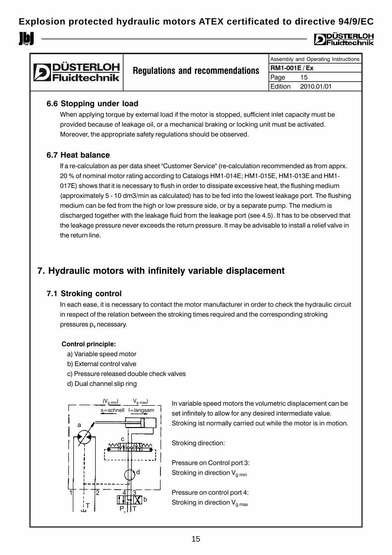
Control principle:
a) Variable speed motor
b) External control valve
c) Pressure released double check valves
d) Dual channel slip ring
In variable speed motors the volumetric displacement can be
set infinitely to allow for any desired intermediate value.
Stroking ist normally carried out while the motor is in motion.
Stroking direction:
Pressure on Control port 3:
Stroking in direction Vg min
Pressure on control port 4:
Stroking in direction Vg max
(Vg min) Vg max)
s=schnell l=langsam
a
c
d
b1 2 4 3
T Pv T
Explosion protected hydraulic motors ATEX certificated to directive 94/9/EC
15
DÜSTERLOH Fluidtechnik GmbH * Im Vogelsang 105 * 45527 Hattingen * +49 / (0) 2324 / 709-0 * Fax +49 / (0) 2324 / 709-110Changes reserved!
Assembly and Operating Instructions
RM1-001E / ExPage 16Edition 2010.01/01
In the no-stroking position, control ports 3 and 4 are relieved to tank without pressure and the slip ring
becomes unpressurized also. The stroking system is then hydraulically locked by pressure released
double check valves.
7.2 Stroking pressure pv
When stroking during operation: pv max=315 bar
for Vg min --> Vg max : pv ≥ 20 bar at all pressures
Vg max --> Vg min : pv ≥ 40 bar and pv ≥ Δp
Stroking pressure can be induced by a separate pump or by an accumulator. lt can also be taken from
the main pressure line to the motor (please note marginal conditions and stroking times - refer to
manufacturer for advice).
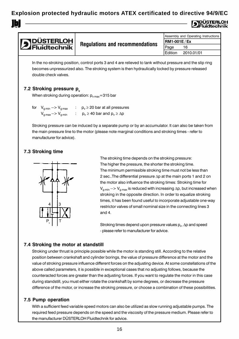
7.3 Stroking timeThe stroking time depends on the stroking pressure:
The higher the pressure, the shorter the stroking time.
The minimum permissible stroking time must not be less than
2 sec..The differential pressure Δp at the main ports 1 and 2 on
the motor also influence the stroking times: Stroking time for
Vg min --> Vg max is reduced with increasing Δp, but increased when
stroking in the opposite direction. In order to equalize stroking
times, it has been found useful to incorporate adjustable one-way
restrictor valves of small nominal size in the connecting lines 3
and 4.
Stroking times depend upon pressure values pv, Δp and speed
- please refer to manufacturer for advice.
7.4 Stroking the motor at standstillStroking under thrust is principle possible while the motor is standing still. According to the relative
position between crankshaft and cylinder borings, the value of pressure difference at the motor and the
value of stroking pressure influence different forces on the adjusting device. At some constellations of the
above called parameters, it is possible in exceptional cases that no adjusting follows, because the
counteracted forces are greater than the adjusting forces. If you want to regulate the motor in this case
during standstill, you must either rotate the crankshaft by some degrees, or decrease the pressure
difference of the motor, or increase the stroking pressure, or choose a combination of these possibilities.
4 3
Pv T
7.5 Pump operationWith a sufficient feed variable speed motors can also be utilized as slow running adjustable pumps. The
required feed pressure depends on the speed and the viscosity of the pressure medium. Please refer to
the manufacturer DÜSTERLOH Fluidtechnik for advice.
Regulations and recommendations
Explosion protected hydraulic motors ATEX certificated to directive 94/9/EC
16
DÜSTERLOH Fluidtechnik GmbH * Im Vogelsang 105 * 45527 Hattingen * +49 / (0) 2324 / 709-0 * Fax +49 / (0) 2324 / 709-110Changes reserved!
Assembly and Operating Instructions
RM1-001E / ExPage 17Edition 2010.01/01
8. Literature
Dr.-Ing. Jürgen KLIE: Infinitely variable hydraulic motors.Published in: „Der Konstrukteur 6/82“
Dr.-Ing. Jürgen KLIE: Characteristics and features ofvariable speed hydraulic hydraulic motors.Published in: „MM - Maschinenmarkt 4/80“
Dr.-Ing. Jürgen KLIE / Start-up behaviour and operation of hydraulic motors with internalDipl.-Ing. Walter Lubos: piston support at lowest speeds.
Paper delivered during the International Conference„Systemschau Antreiben und Bewegen“, Hannover Exhibition 1977.
Dipl.-Ing. Dieter Schneeweiss: Hydraulic feed drive, accuracy to 1/100 mm without pilot valves.Published in: „Fluid 3/77“
Regulations and recommendations
Explosion protected hydraulic motors ATEX certificated to directive 94/9/EC
17
Explosion protected hydraulic motors ATEX certificated to directive 94/9/EC
18

Explosion protected hydraulic motors ATEX certificated to directive 94/9/EC
19
Explosion protected hydraulic motors ATEX certificated to directive 94/9/EC
20DÜSTERLOH Fluidtechnik GmbH * Im Vogelsang 105 * 45527 Hattingen * +49 / (0) 2324 / 709-0 * Fax +49 / (0) 2324 / 709-110Changes reserved!
Assembly and Operating Instructions
RM1-001E / ExPage 20Edition 2010.01/01
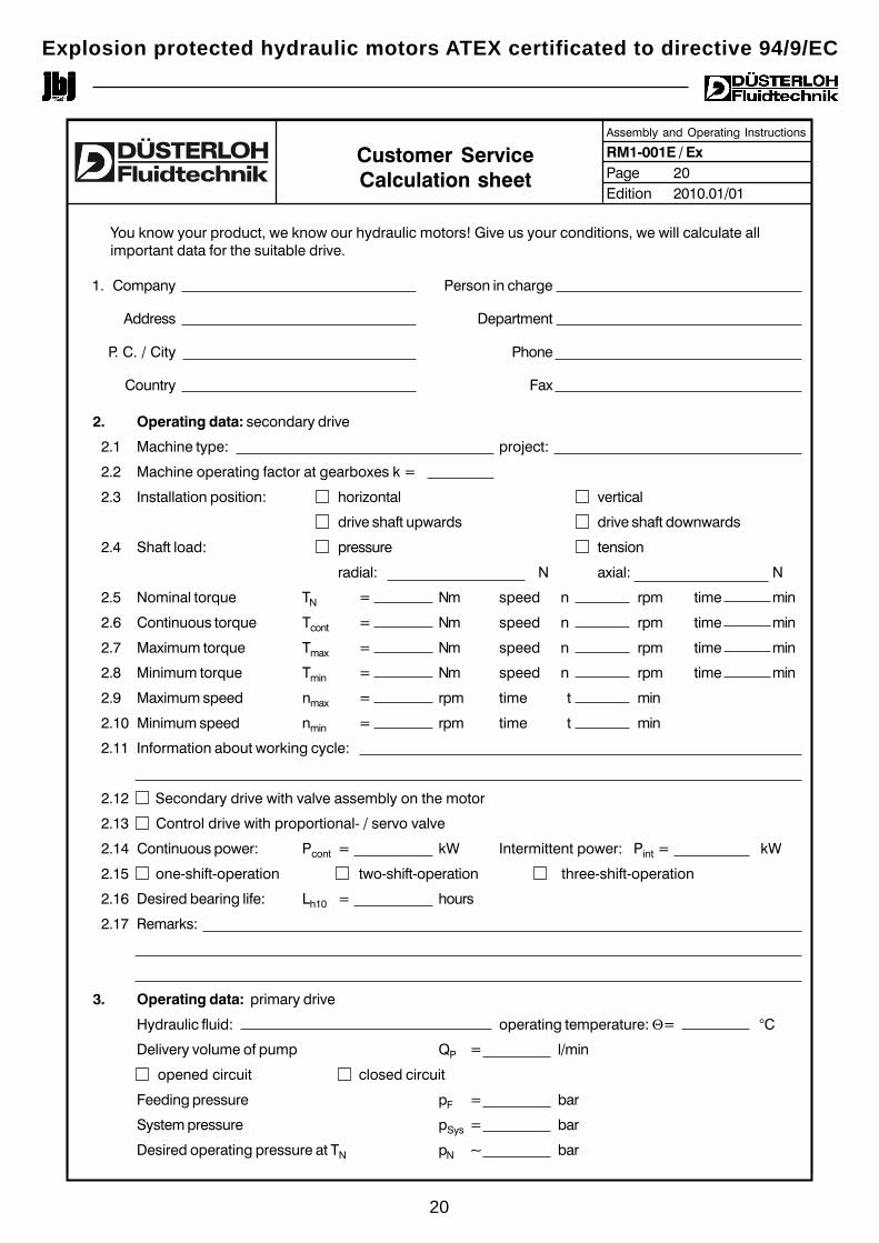
Customer ServiceCalculation sheet
You know your product, we know our hydraulic motors! Give us your conditions, we will calculate allimportant data for the suitable drive.
1. Company Person in charge
Address Department
P. C. / City Phone
Country Fax
2. Operating data: secondary drive
2.1 Machine type: project:
2.2 Machine operating factor at gearboxes k =
2.3 Installation position: horizontal vertical
drive shaft upwards drive shaft downwards
2.4 Shaft load: pressure tension
radial: N axial: N
2.5 Nominal torque TN = Nm speed n rpm time min
2.6 Continuous torque Tcont = Nm speed n rpm time min
2.7 Maximum torque Tmax = Nm speed n rpm time min
2.8 Minimum torque Tmin = Nm speed n rpm time min
2.9 Maximum speed nmax = rpm time t min
2.10 Minimum speed nmin = rpm time t min
2.11 Information about working cycle:
2.12 Secondary drive with valve assembly on the motor
2.13 Control drive with proportional- / servo valve
2.14 Continuous power: Pcont = kW Intermittent power: Pint = kW
2.15 one-shift-operation two-shift-operation three-shift-operation
2.16 Desired bearing life: Lh10 = hours
2.17 Remarks:
3. Operating data: primary drive
Hydraulic fluid: operating temperature: Θ= °C
Delivery volume of pump QP = l/min
opened circuit closed circuit
Feeding pressure pF = bar
System pressure pSys = bar
Desired operating pressure at TN pN ~ bar

jbj Techniques Limited28 Trowers Way Holmethorpe Industrial Estate
Redhill Surrey RH1 2LW. UNITED KINGDOM
01737 767493 [email protected] www.jbj.co.uk
quality products for mechanical & fluid power
registered in England No: 1185469 jbj Techniques Limited is ISO certificated,committed to international coordination &unification of industrial standards.
A range of products ATEX certificatedto directive 94/9/EC requirements


![[Basic concepts for explosion protection] - Scame · [Basic concepts for explosion protection] 1 ... potentially explosive atmospheres in European Union member states. Directive ATEX](https://img.pdfslide.net/doc/110x75/5b7ba6897f8b9a004b8d0e15/basic-concepts-for-explosion-protection-basic-concepts-for-explosion-protection.jpg)