Embed Size (px)
Citation preview

ORNL/TM-2012/601
Export Control Guide: Loose Parts Monitoring
Systems for Nuclear PowerPlants
December 2012
Approved for public release; distribution is unlimited.
DOCUMENT AVAILABILITY Reports produced after January 1, 1996, are generally available free via US Department of Energy (DOE) SciTech Connect. Website http://www.osti.gov/scitech/ Reports produced before January 1, 1996, may be purchased by members of the public from the following source: National Technical Information Service 5285 Port Royal Road Springfield, VA 22161 Telephone 703-605-6000 (1-800-553-6847) TDD 703-487-4639 Fax 703-605-6900 E-mail [email protected] Website http://www.ntis.gov/help/ordermethods.aspx Reports are available to DOE employees, DOE contractors, Energy Technology Data Exchange representatives, and International Nuclear Information System representatives from the following source: Office of Scientific and Technical Information PO Box 62 Oak Ridge, TN 37831 Telephone 865-576-8401 Fax 865-576-5728 E-mail [email protected] Website http://www.osti.gov/contact.html
This report was prepared as an account of work sponsored by an agency of the United States Government. Neither the United States Government nor any agency thereof, nor any of their employees, makes any warranty, express or implied, or assumes any legal liability or responsibility for the accuracy, completeness, or usefulness of any information, apparatus, product, or process disclosed, or represents that its use would not infringe privately owned rights. Reference herein to any specific commercial product, process, or service by trade name, trademark, manufacturer, or otherwise, does not necessarily constitute or imply its endorsement, recommendation, or favoring by the United States Government or any agency thereof. The views and opinions of authors expressed herein do not necessarily state or reflect those of the United States Government or any agency thereof.
iii
December 2012 ORNL/TM-2012/601
Export Control Guide: Loose Parts Monitoring Systems for Nuclear Power Plants
W. D. Rhodes
Office of Nuclear Controls (NA-242) Office of Nonproliferation and International Security
Office of Defense Nuclear Nonproliferation National Nuclear Security Administration
and
D. W. Langenberg
Nonproliferation Technology Group Global Nuclear Security Technology Division
Oak Ridge National Laboratory
Prepared under the direction of Department of Energy
National Nuclear Security Administration Office of Nuclear Controls (NA-242)
Prepared by Nonproliferation Technology
OAK RIDGE NATIONAL LABORATORY Oak Ridge, Tennessee 37831-6285
managed by UT-BATTELLE LLC
for the U.S. DEPARTMENT OF ENERGY
under contract DE-AC05-00OR22725

iv
v
TABLE OF CONTENTS
LIST OF FIGURES ........................................................................................................ vii LIST OF TABLES ........................................................................................................... ix ACRONYMS .................................................................................................................... xi INTRODUCTION..............................................................................................................1 DESCRIPTION OF A MODERN LPMS ........................................................................2 NPP ACOUSTIC EMISSION TESTING ........................................................................6
Detection of Loose Parts by AE Testing .........................................................................6 Loose Parts Monitoring at Hungary’s Paks Nuclear Power Station ................................8
OTHER APPLICATIONS OF AE TESTING ................................................................8
Rotating Machinery Monitoring ......................................................................................9 Leak Monitoring on CANDU Pressure Tubes .................................................................9 Valve Leak Detection ......................................................................................................9 Nonnuclear Applications of AE Monitoring ..................................................................10
Industry Standards Applicable to AE Monitoring ..........................................................10 AE TESTING IMPLEMENTATION ........................................................................... 11
Signal Properties ............................................................................................................11 Sensors ...........................................................................................................................12 BWR LPMS vs PWR LPMS ..........................................................................................13 Acoustic Waveguides .....................................................................................................15 Signal Processing and Recording ..................................................................................15 Baseline Impact Testing .................................................................................................16
SUPPLIERS OF LPMS EQUIPMENT, SOFTWARE, AND SERVICES ................ 17 CONTROLS ON LPMS EXPORTS FROM THE UNITED STATES...................... 23 REFERENCES .............................................................................................................. 246

vi
vii
LIST OF FIGURES
Figure Page
1 Typical AE sensor locations for a four-loop PWR ..................................................3 2 Block diagram of an LPMS .....................................................................................4 3 Control cabinet for the Westinghouse LPMS depicted in Fig. 2 .............................4 4 AE sensor (left) and charge preamplifier (right) for an LPMS ................................5 5 Four channels of impact test signals from South Korea’s Ulchin-4 NPP ................7 6 Typical AE sensors ................................................................................................12 7 Instrumented impact testing hammer .....................................................................16

viii

ix
LIST OF TABLES
Table Page
1 Recommended PWR Sensor Locations (ASME 2010) .........................................13 2 Recommended BWR Sensor Locations (ASME 2010) .........................................13

x

xi
ACRONYMS
ABWR Advanced Boiling Water Reactor
AE Acoustic Emission
AGR Advanced Gas Cooled Reactor
ALPS Advanced Loose Parts monitoring System (an LPMS developed in Hungary for Hungary’s Paks nuclear power station)
AMS Analysis and Measurement Services Corporation
ANL Argonne National Laboratory
APWR Advanced Pressurized Water Reactor
AR Autoregressive
ASME American Society of Mechanical Engineers
ASNT American Society for Nondestructive Testing
ASTM American Society for Testing and Materials
AT Antiterrorism
BIS Bureau of Industry and Security
BNC Bayonet-Neil Concelman (a type of coaxial connector)
BWR Boiling Water Reactor
BWROG BWR Owners’ Group
CANDU Canadian Deuterium Uranium (a type of pressurized heavy water reactor developed in Canada)
CCC Commerce Country Chart
CCL Commerce Control List
CFR Code of Federal Regulations
CNNC China National Nuclear Corporation
CPU Central Processing Unit
CRDM Control Rod Drive Mechanism
DCD Design Control Document
DMIMS Digital Metal Impact Monitoring System (trademarked name of a Westinghouse LPMS)
DOC Department of Commerce
DSP Digital Signal Processor
DVDRW Digital Versatile Disk – Read/Write
EAR Export Administration Regulations
xii
EBR Experimental Breeder Reactor
ECCN Export Control Classification Number
EPRI Electric Power Research Institute
ESBWR Economic Simplified Boiling Water Reactor
FRP Fiberglass Reinforced Plastic
IAEA International Atomic Energy Agency
IEC International Electrotechnical Commission
I/O Input / Output
LMFBR Liquid Metal Fast Breeder Reactor
LPMS Loose Parts Monitoring System
LWR Light Water Reactor
MCB Main Control Board
NDE Nondestructive Evaluation
NP Nuclear Nonproliferation
NPER Nuclear Power Engineering – Reactor, a PAEC Directorate
NPP Nuclear Power Plant
NRC Nuclear Regulatory Commission
PAC Physical Acoustics Corporation
PAEC Pakistan Atomic Energy Commission
PCI Peripheral Component Interconnect
PWR Pressurized Water Reactor
RCS Reactor Coolant System
RFO Reactor Fueling Outage
RTRP Reinforced Thermosetting Resin Pipe
RV Reactor Vessel
SCSI Small Computer System Interface
SPRT Sequential Probability Ratio Test
TEC Technology for Energy Corporation
VVER Vodo-Vodyannoy Energeticheskiy Reactor, a Russian PWR design
1
INTRODUCTION
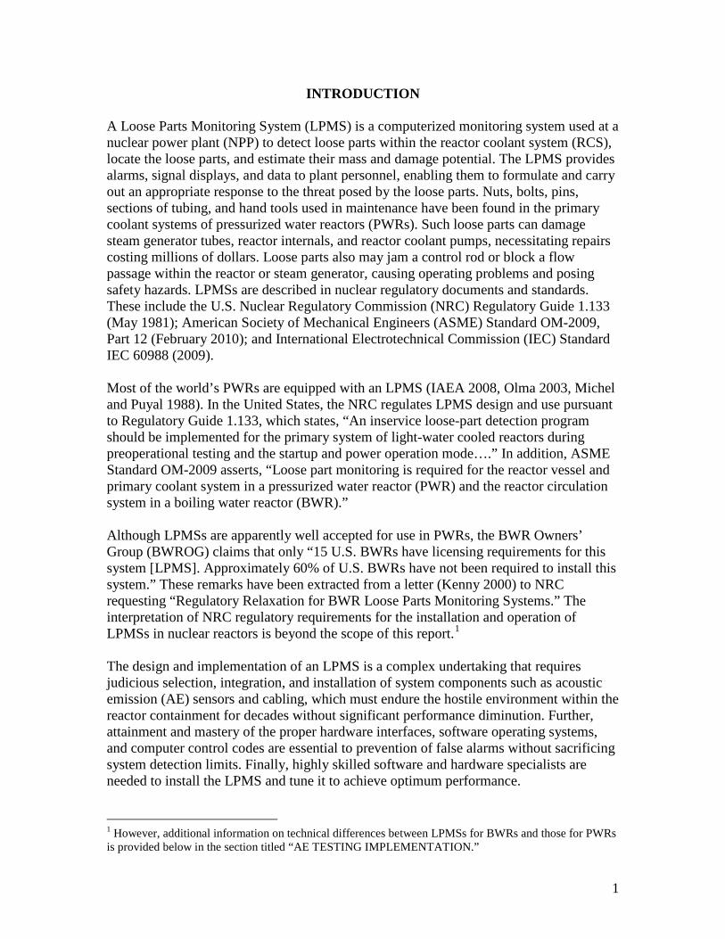
A Loose Parts Monitoring System (LPMS) is a computerized monitoring system used at a nuclear power plant (NPP) to detect loose parts within the reactor coolant system (RCS), locate the loose parts, and estimate their mass and damage potential. The LPMS provides alarms, signal displays, and data to plant personnel, enabling them to formulate and carry out an appropriate response to the threat posed by the loose parts. Nuts, bolts, pins, sections of tubing, and hand tools used in maintenance have been found in the primary coolant systems of pressurized water reactors (PWRs). Such loose parts can damage steam generator tubes, reactor internals, and reactor coolant pumps, necessitating repairs costing millions of dollars. Loose parts also may jam a control rod or block a flow passage within the reactor or steam generator, causing operating problems and posing safety hazards. LPMSs are described in nuclear regulatory documents and standards. These include the U.S. Nuclear Regulatory Commission (NRC) Regulatory Guide 1.133 (May 1981); American Society of Mechanical Engineers (ASME) Standard OM-2009, Part 12 (February 2010); and International Electrotechnical Commission (IEC) Standard IEC 60988 (2009). Most of the world’s PWRs are equipped with an LPMS (IAEA 2008, Olma 2003, Michel and Puyal 1988). In the United States, the NRC regulates LPMS design and use pursuant to Regulatory Guide 1.133, which states, “An inservice loose-part detection program should be implemented for the primary system of light-water cooled reactors during preoperational testing and the startup and power operation mode….” In addition, ASME Standard OM-2009 asserts, “Loose part monitoring is required for the reactor vessel and primary coolant system in a pressurized water reactor (PWR) and the reactor circulation system in a boiling water reactor (BWR).” Although LPMSs are apparently well accepted for use in PWRs, the BWR Owners’ Group (BWROG) claims that only “15 U.S. BWRs have licensing requirements for this system [LPMS]. Approximately 60% of U.S. BWRs have not been required to install this system.” These remarks have been extracted from a letter (Kenny 2000) to NRC requesting “Regulatory Relaxation for BWR Loose Parts Monitoring Systems.” The interpretation of NRC regulatory requirements for the installation and operation of LPMSs in nuclear reactors is beyond the scope of this report.1 The design and implementation of an LPMS is a complex undertaking that requires judicious selection, integration, and installation of system components such as acoustic emission (AE) sensors and cabling, which must endure the hostile environment within the reactor containment for decades without significant performance diminution. Further, attainment and mastery of the proper hardware interfaces, software operating systems, and computer control codes are essential to prevention of false alarms without sacrificing system detection limits. Finally, highly skilled software and hardware specialists are needed to install the LPMS and tune it to achieve optimum performance. 1 However, additional information on technical differences between LPMSs for BWRs and those for PWRs is provided below in the section titled “AE TESTING IMPLEMENTATION.”
2
Minimization of loose part false alarms – a common problem with older systems – is one of the most important aspects of LPMS design and implementation. Modern digital LPMSs with advanced loose part detection criteria (minimizing false alarms) and advanced diagnostic tools (minimizing testing time) are deployed in NPPs worldwide. The term “loose parts monitoring system” may suggest a narrowly focused technology with a limited range of applicability. However, the basic technology – frequency response function measurement of system permutation events – is widely used and highly sophisticated. For example, Rhodes et al (2000) measured the frequency response function of the Experimental Breeder Reactor-II (EBR-II)2 and demonstrated the reactor’s inherent feedback stability at full-power operation, thereby validating and advancing breeder reactor technology. The technology has also demonstrated remarkable versatility, with applications in systems that monitor the condition of rotating machinery; systems that detect leaks in steam generators, steam lines, and valves; and systems that detect flaws and crack propagation in construction materials. A would-be proliferator would not likely expend the resources needed to design and configure a unique LPMS. Rather, the aspiring proliferator would attempt to procure a complete package available from any of a number of worldwide vendors. Therefore, national governments wishing to prevent the spread of nuclear weapons have implemented controls on LPMS exports. This report describes a typical LPMS, emphasizing its application to the RCS of a modern NPP. The report also examines the versatility of AE monitoring technology by describing several nuclear applications other than loose parts monitoring, as well as some non-nuclear applications. In addition, LPMS implementation requirements are outlined, and LPMS suppliers are identified. Finally, U.S. export controls applicable to LPMSs are discussed.
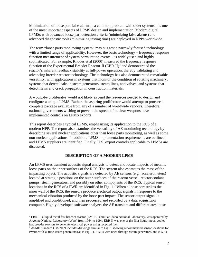
DESCRIPTION OF A MODERN LPMS An LPMS uses transient acoustic signal analysis to detect and locate impacts of metallic loose parts on the inner surfaces of the RCS. The system also estimates the mass of the impacting object. The acoustic signals are detected by AE sensors (e.g., accelerometers) located at strategic positions on the outer surfaces of the reactor vessel, reactor coolant pumps, steam generators, and possibly on other components of the RCS. Typical sensor locations in the RCS of a PWR are identified in Fig. 1.3 When a loose part strikes the inner wall of the RCS, the sensors produce electrical output signals in response to the mechanical vibration produced by the loose part impact. The sensor output signal is amplified and conditioned, and then processed and recorded by a data acquisition computer. Highly developed software analyzes the AE transient and differentiates loose
2 EBR-II, a liquid metal fast breeder reactor (LMFBR) built at Idaho National Laboratory, was operated by Argonne National Laboratory (West) from 1964 to 1994. EBR-II was one of the first liquid-metal-cooled fast breeder reactors to generate electrical power using recycled fuel. 3 ASME Standard OM-2009 includes drawings similar to Fig. 1 showing recommended sensor locations for PWRs with U-tube steam generators (as in Fig. 1), PWRs with once-through steam generators, and BWRs.
3
part impact signals from noise. Modern digital systems have stringent multi-level alarm criteria, which minimize false alarms due to noise, thus minimizing unnecessary operator distractions and the need for data analysis by a human expert.
Fig. 1. Typical AE sensor locations for a four-loop PWR. Sensors (labeled transducers in this diagram) are placed on the outer surfaces of the reactor vessel (RV), reactor coolant pumps, and U-tube steam generators. Some sensor locations are obscured by RCS components. (© 2006 Westinghouse Electric Company LLC. Used with permission. Unauthorized use is strictly prohibited.) LPMS components face demanding functional requirements. AE sensors are mounted on the hot surfaces of RCS components, where they must withstand temperatures of 325°C (617°F) or more, integrated gamma radiation doses that may exceed 108 Gy (1010 rad), and integrated neutron fluxes that may exceed 1018 neutrons/cm2. The sensors also must be sensitive to mechanical vibrations at frequencies up to 20 kHz and be immune to electrical and electromagnetic disturbances. The extreme environmental conditions also impact the requirements for selection, installation, and operation of the AE preamplifiers (preamps), which may be located outside the reactor containment enclosure or inside the reactor containment, where temperatures and radiation levels are high. Because the preamps are located far from the AE sensors,4 charge preamplifiers (vs. more common voltage preamps) are used to minimize signal degradation in the cables that connect the sensors to the preamps. The limited access to equipment within the reactor compartment imposes additional constraints on system design. For example, the ability to remotely change the gain of the preamps and remotely run diagnostic tests at specified test intervals is desirable.5 4 A preamp located outside the containment may be up to 100 m from the sensor it serves. A preamp inside the containment is located as far as practicable from its sensor in order to conform to the temperature and radiation limitations of modern electronics. 5 One such test checks the response of the preamp to a sine wave input signal of known amplitude and frequency. In another test, the AE sensors are excited remotely to test their operability. Remote gain adjustment and diagnostic functions are very important to maintaining LPMS integrity.

4
Digital data acquisition software acquires signals from AE sensors and performs real-time feature extraction, processing, and evaluation to identify loose part impacts and assess their significance. A block diagram showing key components of a Westinghouse LPMS is presented in Fig. 2. Most of the equipment in Fig. 2 is housed in the control cabinet shown in Fig. 3. An AE sensor and a charge preamplifier are shown in Fig. 4.
Fig. 2. Block diagram of an LPMS. In this system, the sensors and the preamps are inside the reactor containment. Acronyms are defined in the Acronym list. (© 2006 Westinghouse Electric Company LLC. Used with permission. Unauthorized use is strictly prohibited.)
Fig. 3. Control cabinet for the Westinghouse LPMS depicted in Fig. 2. (© 2006 Westinghouse Electric Company LLC. Used with permission. Unauthorized use is strictly prohibited.)
5
AE sensor (left foreground) and cable. Charge preamplifier.
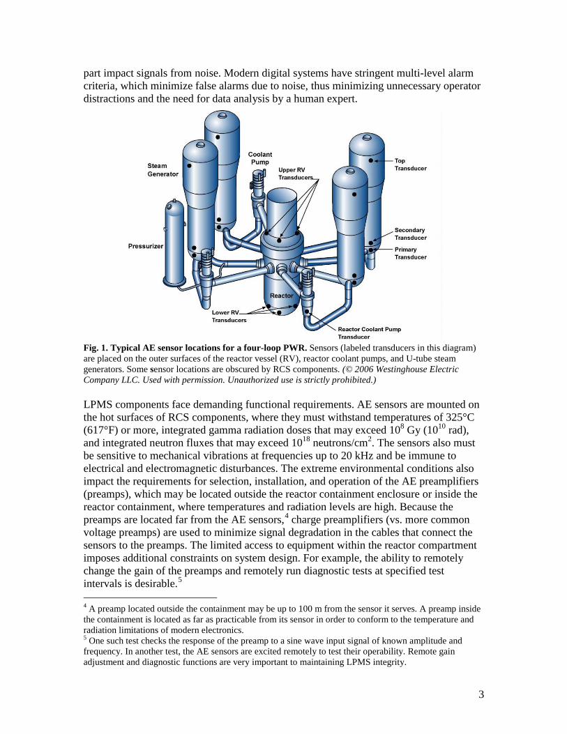
Fig. 4. AE sensor (left) and charge preamplifier (right) for an LPMS. An Inconel housing measuring about 20-mm wide × 20-mm tall (0.79 in. × 0.79 in.) protects the sensor’s internal components from the harsh environment within the containment of a nuclear reactor. The sensor shown can operate at temperatures as high as 540°C (~1000°F), and can withstand intense radiation. The charge preamplifier amplifies the output of the AE sensor. (Source: Loose Parts Monitoring for Reactor Safety, a 2009 brochure describing the Sentry LPMS, a product of Physical Acoustics Corporation, a member of the Mistras Group Inc. See www.mistrasgroup.com.) Today’s LPMS detection methods and alarm criteria are vastly improved relative to those of older systems. These latter systems had a poor reputation due to high false alarm rates, frequent failure to detect potentially damaging loose parts, and the need to follow up an alarm with a decision-making process requiring careful human examination of waveforms replayed on an oscilloscope. Today’s systems provide automated and user-demand frequency analysis to identify loose part impact signals hidden in the background noise of the NPP. The systems are seismically certified and tested, and they are certified to operate in the presence of electromagnetic interference. Modern loose parts monitoring software performs many functions, including timed or on-demand waveform capture, frequency analysis, pattern recognition, and correlation analysis to aid in loose part recognition, location, and mass estimation. In addition, background noise may be monitored and analyzed to detect leaks in the RCS, and signals from the sensors may be monitored to assess the condition of rotating machinery such as reactor coolant pumps. The software also creates multiple data presentation screens that facilitate the identification and understanding of possible loose part impacts. A typical LPMS employs a multilevel alarm process that includes the following steps:
1. A suspected loose part signal is detected by high or otherwise unusual AE activity. 2. The alarm determination process is initiated by applying pattern recognition
techniques to the AE signal. 3. If pattern recognition (Step 2) does not rule out the occurrence of a loose part impact,
frequency analysis is performed to compare the high-frequency and low-frequency content of the signal with alarm criteria for a loose part.
4. If alarm criteria of Step 3 are met, a signal is sent to the control room to alert the operators that a loose part has been detected. In addition, waveform capture and analysis are initiated to estimate the location and mass of the loose part.
Using sophisticated techniques such as these to distinguish between background events and loose part impacts, modern LPMSs have demonstrated false alarm rates and missed

6
alarm rates well below 1% (IAEA, 2008). Each installed LPMS has its own signature characteristics (unique from those of other installations) requiring each LPMS (hardware and software) to be expressly tuned to the specific installation.
NPP ACOUSTIC EMISSION TESTING
Detection of Loose Parts by AE Testing
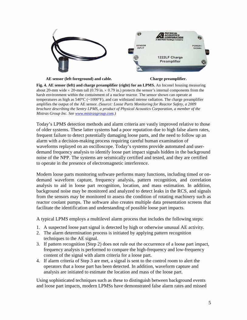
During the last 35 years, many reports have been published on the application of AE testing techniques to loose parts monitoring in NPPs. Numerous examples can be found in the reference list at the end of this report. For instance, Chang et al. (2004) describe the development of an LPMS for Unit 4 of the Ulchin nuclear power station in South Korea.6 Figure 5 shows signals from AE sensors mounted on one of the Unit 4 steam generators. Similar signals can be seen on the LPMS display screen in Fig. 3. The loose part sensor locations at Ulchin-4 are similar to those shown in Fig. 1. The data shown in Fig. 5 suggest a technique for estimating the location of an impact (by an impact testing hammer or a loose part). The signal at the top of Fig. 5, which is the amplified output from a sensor labeled V-108, has a sharp peak at a time of about 15.2 ms.7 About 1.8 ms later (at a time of 17 ms), a peak appears in the signal from Sensor V-107 (second trace from the top of Fig. 5). The signals produced by sensors V-106 and V-105 have lower amplitudes and exhibit different time delays relative to the signal from sensor V-108. Given the known locations of the sensors and the measured time delays of the signals, it is possible to estimate (by triangulation) the location of the point at which an object strikes the inner surface of the RCS. Loose parts monitoring within the coolant systems of commercial light-water reactors (LWRs) has been covered by U.S. government regulations since the late 1970s (Persio 1999). The technology has matured over the past three decades and is now in use at most of the world’s NPPs. Loose part monitoring was originally compliant with NRC Regulatory Guide 1.133, September 1977 (Rev. 1 published May 1981). Early problems (e.g., high false alarm rates, failure to detect loose parts) led to systematic reviews by Oak Ridge National Laboratory (Kryter et al. 1977 and 1984), which showed that LPMS performance in 1984 had improved relative to that in 1977, but there were still deficiencies related to signal propagation and the frequency range and distinguishing characteristics of valid signals.
6 Ulchin is a six-unit nuclear power station. Each of the six units has a net electrical power output of about 990 MW. The reactor of each unit is a two-loop PWR. 7 For each of the four traces shown in Fig. 5, the horizontal axis is the time in milliseconds (relative to a known zero) and the vertical axis (labeled “G” in Fig. 5) is the measured acceleration relative to the acceleration due to gravity. The accelerations plotted in Fig. 5 were measured by four accelerometers (one for reach trace in Fig. 5). Note that different scales are used on the vertical axes of the four graphs.

7
Fig. 5. Four channels of impact test signals from South Korea’s Ulchin-4 NPP. Test data were obtained from four sensors mounted on the surface of a Unit 4 steam generator that was excited by an impact testing hammer during pre-operational testing. Signals from actual loose part impacts have a similar appearance. (Source: Chang, Y. W. et al. 2004.) The Electric Power Research Institute (EPRI) (Mayo et al. 1988) conducted an LPMS research project using metal impact theory and experimental data to develop a quantitative description of loose parts, yielding signal amplitude and frequency as a function of impact energy and mass, signal transmission, and sensor response. This effort enabled Mayo and his collaborators to make recommendations for sensor mounting, system calibration, signal processing, and signal interpretation. The EPRI project was coordinated with and ultimately led to ASME Standard OM-12 on loose part monitoring
8
in LWR power plants.8 Indeed, Persio (1999) reported that systems meeting the OM-12 standard are more sensitive to impact events than those solely meeting NRC Guide 1.133. Further, newer systems meeting the ASME standard are less prone to the false alarms that plagued first generation systems based solely on the NRC Guide. Loose Parts Monitoring at Hungary’s Paks Nuclear Power Station
As indicated previously, loose parts monitoring in NPPs is based on detection and analysis of signals produced by sensors mounted on the outer walls of components making up the RCS. Impacts on the inner walls of the RCS are manifested as bursts in the sensor output signals. (Such bursts can be seen in the signals shown in Figs. 3 and 5.) Because the bursts are embedded in the high-acoustic background noise of the RCS, identification and localization of loose parts is a difficult task. Today’s most advanced LPMSs use highly sophisticated methods to identify impact events. Autoregressive (AR) modeling and the sequential probability ratio test (SPRT) are two of the most sensitive methods to distinguish loose part impacts from events responsible for background noise in the RCS (IAEA 2008). The application of AR models and the SPRT to loose part monitoring in NPPs has been championed by several Hungarian authors (Pokol and Por 2006, Por et al. 2003, Por and Szappanos 2001), who have developed the Advanced Loose Parts monitoring System (ALPS) for use at Hungary’s Paks nuclear power station.9 In addition to AR modeling and the SPRT, ALPS uses short-time Fourier transforms and continuous wavelet transforms in its algorithms for identification, localization, and characterization of loose parts (Pokol and Por 2006).10 The ALPS is illustrative of many modern LPMS installations worldwide.
OTHER APPLICATIONS OF AE TESTING AE is the elastic energy released by materials when they undergo deformation (Miller and McIntire 1987). This rapid energy release causes stress waves (transient elastic waves) that radiate from the source and are detected and monitored by sensors placed on material surfaces. AE testing is a nondestructive testing technique11 that was first used more than 60 years ago to detect deformation and degradation of engineering materials and structures. As discussed above, AE testing methods have since been adapted to detect and characterize structure-borne sound caused by metallic impacts on material surfaces (e.g., loose part impacts). AE testing techniques are also used to monitor rotating machinery vibration and to detect noise caused by leaking fluids. 8 The ASME standard was called OM-12 when it was under development in the late 1980s. The latest version of the ASME loose part monitoring standard can be found in Part 12 of ASME Standard OM-2009, which was issued on 26 February 2010 (ASME 2010). 9 Paks is a four-unit nuclear power station at which the reactor of each unit is a VVER-440/V213, a PWR of Russian design having a net electrical power output of about 440 MW. 10 Detailed discussions of these advanced techniques are beyond the scope of this report. Readers interested in the application of such tools to loose part monitoring may wish to consult the references cited. 11 AE testing is one of a number of nondestructive testing techniques, including visual testing, ultrasonic testing, liquid penetrant testing, electromagnetic testing, magnetic particle testing, and radiologic testing using neutrons, gamma rays, or X-rays.
9
Rotating Machinery Monitoring
The AE sensors used for loose part monitoring can also measure vibration of rotating machinery such as reactor coolant pumps (Weiss and Mayo 1991). In fact, an NPP’s vibration detection system and its LPMS typically share sensors and preamplifiers, thereby reducing the costs of equipment and maintenance (IAEA 2008). The same sensor can be used for both applications if the location of the sensor and the orientation of its sensitive axis are arranged to provide meaningful data for both functions. Sensors for monitoring coolant pump vibration and loose part impacts have also been used to identify sources of noise transmitted to the RCS through auxiliary piping and to diagnose problems that may result in loose parts entering the reactor vessel. For example, an NPP operator used an LPMS sensor mounted near a recirculation flow control valve to diagnose rubbing of a recirculation pump shaft. Analysis of the data led to a decision to stop the pump and replace its internals. Inspection of the pump shaft revealed a 320° circumferential crack (Weiss and Mayo 1991). Leak Monitoring on CANDU Pressure Tubes
AE testing has also been used to identify leaking pressure tubes in Canadian deuterium uranium (CANDU) NPPs (Benz 1998). AE testing augments the system currently used for continuous online monitoring, which employs instruments that detect moisture in the gas flowing through the annular gaps between the pressure tubes and the calandria tubes. The presence of moisture in these “gas gaps” is an indicator of pressure tube leakage.12 Because four to twelve pressure tubes are linked to one independent gas-gap circuit, only a group of leaking pressure tubes can be identified, but AE testing can supplement gas-gap monitoring by identifying specific leaking pressure tubes (Miller and McIntire 1987). A two-step procedure is used. First, a detector of airborne sound monitors the reactor’s overall sound level. Second, the detector is scanned across the reactor face with the fueling machine retracted, yielding a full reactor survey and pinpointing specific leaking pressure tubes. The AE test is performed only when gas-gap moisture indicates the existence of pressure tube leakage. Because CANDU pressure tubes rarely leak, AE tests are performed infrequently. Moreover, continuous online AE testing is impractical due to the large number of sensors and cables needed. The small benefit that might be derived from continuous AE testing does not justify the cost. Valve Leak Detection
Online AE monitoring of valves can detect leakage, detect anomalous valve noise from sources other than leakage, and monitor the valve opening (for some types of valves). The major advantage of this technique over others is instantaneous notification of 12 CANDU reactor fuel bundles are contained in pressure tubes through which high-pressure heavy water is pumped to extract heat from the fuel. Each pressure tube is contained within another tube called a calandria tube, which is one of many such tubes contained in the calandria, a large vessel containing low-pressure heavy water that serves as the reactor’s moderator. Small compressors circulate carbon dioxide gas through the annular gaps between the pressure tubes and the calandria tubes. The presence of heavy water in the circulating gas is an indication of pressure tube leakage. (A CANDU 6 NPP, with a net electrical power output of 600 MW(e) or more, has a calandria fitted with 380 pressure tubes.)

10
aberrant conditions. Further, leak detection is not limited to leaks across the valve seat or leaks through the pressure boundary. AE monitoring can detect any leak that generates significant turbulence as fluid passes through an area of restricted flow. Indeed, the technique has been used on check valves, needle valves, control valves, and safety relief valves (Haynes 1990, Tsunoda et al. 1985, Nakamura et al. 1985, and Hartman et al. 1979). Finally, when used in conjunction with other techniques, AE monitoring can provide more complete information about the operation of the valve (e.g., position and motion of valve internals and estimates of flow rates and leak rates) (Haynes 1990). Other techniques that can enhance AE leak detection include ultrasonic inspection, magnetic flux signature analysis, and external magnetic excitation methods. Nonnuclear Applications of AE Monitoring
AE testing is a well-developed technology for monitoring structures such as pressure vessels, piping systems, or other structures that are subjected to mechanical or thermal stress. For example, the technique is used in the chemical industry to assess the structural integrity of pressure vessels, chemical reactors, columns, boilers, deaerators, storage tanks, and pipework (Fowler 1987, Lees 1996). AE systems are also used to examine compressed gas cylinders and railroad tank cars during pressure testing. Leak detection is another common nonnuclear application. For instance, since the early 1980s operators of fossil-fuel power plants have applied AE leak detection methods to boilers, feedwater heaters, and piping (Babcock & Wilcox 1992). Industry Standards Applicable to AE Monitoring
Standardized methods for performing AE examinations are detailed in Section V of the ASME Boiler and Pressure Vessel Code. For example, Article 12 of Section V describes AE examination of metallic vessels during pressure testing, and Article 13 covers requirements for continuous AE monitoring of metal or nonmetal pressure vessels for nuclear or nonnuclear service (ASME 2011). The American Society for Testing and Materials (ASTM) has published a number of AE-related standards, including ASTM E 1211-07, “Standard Practice for Leak Detection and Location Using Surface-Mounted Acoustic Emission Sensors,” which “describes a passive method for detecting and locating the steady-state source of gas and liquid leaking out of a pressurized system. The method employs surface-mounted acoustic emission sensors … or sensors attached to the system via acoustic waveguides … and may be used for continuous in-service monitoring and hydrotest monitoring of piping and pressure vessel systems. High sensitivities may be achieved, although the values obtainable depend on sensor spacing, background noise level, system pressure, and type of leak” (ASTM 2007). A partial list of relevant ASTM Standards is presented below: E 569 Standard Practice for Acoustic Emission Monitoring of Structures During Controlled Stimulation, E 650 Guide for Mounting Piezoelectric Acoustic Emission Sensors, E 750 Practice for Characterizing Acoustic Emission Instrumentation, E 1067 Standard Practice for Acoustic Emission Examination of Fiberglass Reinforced Plastic (FRP) Resin Tanks/Vessels,
11
E 1106 Method for Primary Calibration of Acoustic Emission Sensors, E 1118 Standard Practice for Acoustic Emission Examination of Reinforced
Thermosetting Resin Pipe (RTRP), E 1139 Standard Practice for Continuous Monitoring of Acoustic Emission from Metal
Pressure Boundaries, E 1211 Standard Practice for Leak Detection and Location Using Surface-Mounted
Acoustic Emission Sensors, E 1316 Standard Terminology for Nondestructive Examinations, E 2191 Standard Practice for Examination of Gas-Filled Filament-Wound Composite
Pressure Vessels Using Acoustic Emission, and E 2374 Guide for Acoustic Emission System Performance Verification.
AE TESTING IMPLEMENTATION A loose part striking a point on the inside wall of an RCS creates stress waves that radiate from the point of impact as structure-borne sound. An LPMS detects and interprets structure-borne sound from several sources, including loose part impacts, background noise, and metallic impacts not caused by loose parts within the RCS. Structure-borne sound is manifested as transient acoustic signals, which the LPMS detects using an array of sensors mounted at carefully chosen locations on the external walls of the RCS. A modern LPMS uses sophisticated techniques to interpret the output from the sensors and determine whether a significant loose part impact has occurred, and, if so, estimate the location of the point of impact and the mass of the impacting object. The ASTM defines AE as “the class of phenomena whereby transient stress/displacement waves are generated by the rapid release of energy from localized sources within a material, or the transient waves so generated” (ASTM 2011). The phenomena detected and interpreted by an LPMS clearly fit this definition. Because an LPMS depends on AE testing technology for its successful implementation, the following paragraphs are provided to augment the discussion of AE testing presented in the preceding sections of this report. A number of reviews of AE testing can be found in the technical literature; for example, Volume 5 of the Nondestructive Testing Handbook (Miller and McIntire 1987) covers the general technical foundation for the technology and presents a number of applications. This classic was published 25 years ago by the American Society for Nondestructive Testing (ASNT). For the most recent edition of this handbook, see Miller et al. 2005. The following paragraphs are largely based on the work of Weiss and Mayo 1991 and the ASME Standard on “Loose Part Monitoring in Light-Water Reactor Power Plants” (ASME 2010). Signal Properties
Loose part impacts against the inner surface of the RCS primarily excite bending waves in the walls of the RCS. Weiss and Mayo 1991 describe a research project in which metal impact theory and experimental data were used to develop a quantitative description of loose part impact signals. This approach was used to determine relationships between the
12
amplitude and frequency content of the plate bending waves and the energy and mass of the impacting object, signal transmission characteristics, and sensor response. These relationships were used to develop recommended practices for specifying sensors, mounting sensors, processing signals, interpreting signals, and calibrating the system. For example, calculations that compare very well with experimental data show that most of the frequency content of the signals falls in the range from 1 to 10 kHz for impacting objects weighing between 0.15 lb (0.068 kg) and 32 lb (14.5 kg). Specifications for the frequency response and the first resonant frequency of LPMS accelerometers are based in part on such results. Additional details pertaining to the work described by Weiss and Mayo 1991 are presented in Mayo et al. 1988. Sensors
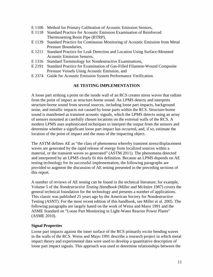
The website of Physical Acoustics Corporation (PAC, www.pacndt.com), a leader in AE testing technology, an LPMS supplier, and an AE sensor supplier, states, “The single most important factor in acoustic emission (AE) testing is the selection of the AE sensor (transducer).” Typical AE sensors are shown in Figs. 4 and 6.
Fig. 6. Typical AE sensors. (Source: website of
Physical Acoustics Corporation – www.pacndt.com.) LPMS performance is affected by the number of sensors used, their locations, and the methods used to attach them to the wall of the RCS. These factors influence the ability of the LPMS to locate noise sources and its ability to interpret the amplitude and frequency content of detected signals (Weiss and Mayo 1991). General requirements for piezoelectric sensors, as well as sensor mounting methods, sensor installation requirements, and preferred sensor locations are presented in Part 12 of AMSE Standard OM-2009 (ASME 2010). This Standard recommends sensor locations for PWRs with U-tube steam generators, PWRs with once-through steam generators, and BWRs. The recommendations are discussed in the Standard’s text, depicted on three drawings, and listed in two tables. The tables are reproduced below as Tables 1 and 2.
13
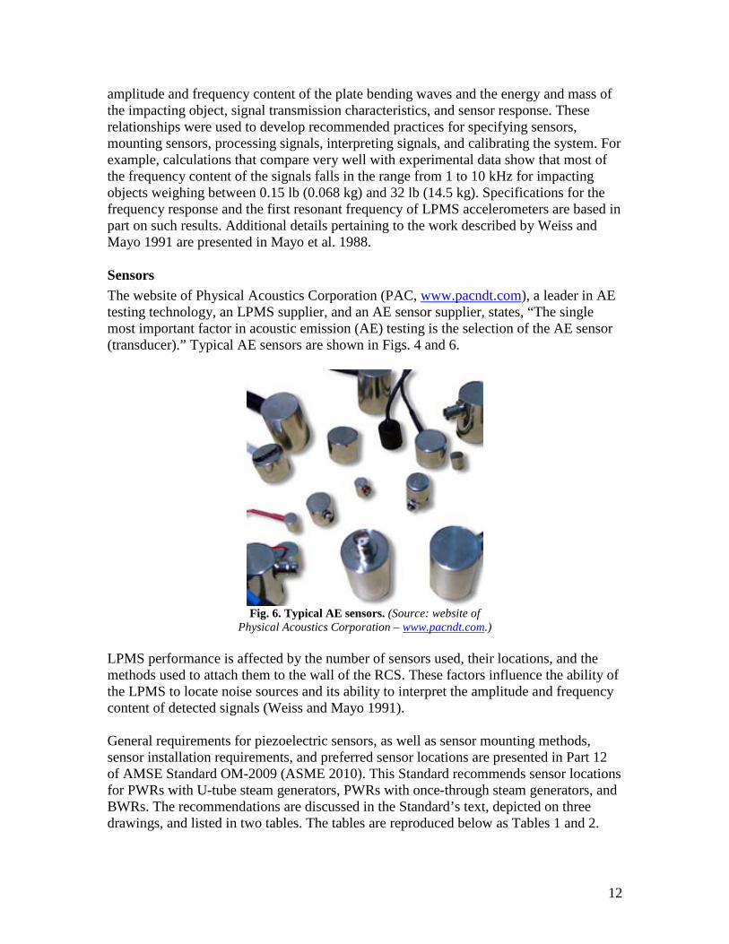
Table 1 lists recommended sensor locations for PWRs, and Table 2 lists recommended sensor locations for BWRs.
Table 1. Recommended PWR sensor locations (ASME 2010) Location Number of sensors
Reactor vessel, upper 3 Reactor vessel, lower 3 Steam generator (each) 3 Reactor coolant pump (each) 1
Table 2. Recommended BWR sensor locations (ASME 2010) Location Number of sensors
Main steam outlet elevation 2 Feedwater inlet elevation 4 Recirculation water outlet elevation 2 Recirculation pump (each) 1 Recirculation discharge pipe (each) 1 Reactor vessel bottom 3 The ASME drawing for PWRs with U-tube steam generators is very similar to Fig.1; however, Fig. 1 suggests that the sensors near the bottom of the RV are attached directly to the surface of the RV, whereas the ASME drawing shows, and the text states, “The three lower reactor vessel accelerometers shall be mounted to the incore guide tubes within 18 in. (0.45 m) of the reactor vessel.”13 The ASME Standard also asserts, “In plants without lower vessel incore guide tubes, the lower reactor vessel accelerometers shall be mounted to the reactor vessel.” Thus, Fig. 1 can be interpreted as a depiction of a PWR without lower vessel guide tubes. BWR LPMS vs PWR LPMS
Tables 1 and 2 highlight significant differences between an LPMS for a PWR and an LPMS for a BWR; these differences obviously reflect the substantial differences in reactor design and RCS design (e.g., absence of a steam generator in the RCS of a BWR). It is also noteworthy that technical literature on LPMS applications usually focuses on PWRs, in part because the PWR is the world’s dominant reactor type. As of 31 December 2010, only 92 (21%) of the world’s 441 operational nuclear power reactors were BWRs, whereas 269 reactors (61%) were PWRs. Moreover, only 4 (6%) of the 67 reactors under construction are BWRs and 56 (84%) are PWRs (IAEA 2011). The differences between a PWR and a BWR also may have led to differences in LPMS performance. On September 29, 2006, General Electric announced its intention “to delete the Loose Parts Monitoring System (LPMS) from the ESBWR design” defined in a design control document (DCD) that had previously been submitted to the NRC. (ESBWR is an acronym meaning “Economic Simplified BWR.”) Deletion of the LPMS
13 In-core guide tubes penetrate the wall of the RV. The guide tubes provide passageways through which measuring instruments (e.g., neutron flux detectors) can be inserted into the core of the reactor.
14
from the ESBWR design was justified by a previous NRC decision to approve LPMS regulatory relaxations that had been requested by the BWROG. Documentation for these actions can be found on the NRC website at http://pbadupws.nrc.gov/docs/ML0628/ ML062890058.pdf. The following italicized paragraphs have been cut from this website and pasted here:
GE intends to delete the Loose Parts Monitoring System (LPMS) from the ESBWR Design currently described in DCD Tier 2 Subsection 4.4.5, and as a consequence the DCD Tier 2 Subsection 4.4.5 will be deleted. The basis for deleting the LMPS is discussed in the following paragraphs.
In a letter addressed to Mr. James Kenny, Chairman [of the] BWR Owners' Group (BWROG), dated January 25, 2001, the NRC approved the Loose Parts Monitoring System regulatory relaxations that were requested by the BWROG. The January 25, 2001 NRC approval letter and the associated safety evaluation that defines the basis for NRC acceptance of the topical report were enclosed in Reference 4.4-7.1.
The NRC Safety Evaluation conclusion section contained in Reference 4.4-7.1 states (in Section 4.0 first three paragraphs):
"In Topical Report NEDC-32975P, "Regulatory Relaxation for BWR Loose Parts Monitoring Systems," the BWROG reported on the effectiveness of the LPMS installed in some BWR plants and proposed eliminating the LPMS requirements. The BWROG stated that although loose parts have been detected on a few occasions: (1) the BWROG did not identify any BWR that was shutdown due to the impact of loose parts, (2) no LPMS detected a failed or weakened safety-related component, (3) licensees employ an aggressive foreign material exclusion program and underwater inspection during refueling outages to ensure loose parts do not accumulate in the reactor vessel, (4) experience also shows that components left in the reactor system are retained in low flow regions, which do not pose a safety problem, and (5) small metallic filings and other similar debris could contribute to fuel cladding damage, but the LPMS would not detect this class of debris and the industry has installed debris filters into the fuel support pieces which may reduce fuel cladding damage due to fretting."
"The staff finds that operating history does indicate that LPMS did detect weakened or degraded safety related components as well as damage to components due to loose parts inadvertently left during maintenance or refueling. However, the LPMS in use are not reliable or sensitive enough to provide the safety benefits envisioned by RG 1.133. Loose parts can be detected by the normal plant process and monitoring systems and also through visual inspections. Also, operating history does not show a higher incidence or occurrence of damage to safety-related components in plants that have no LPMS installed. The staff concurs that the safety benefits of the LPMS do not appear to be commensurate with the cost of maintenance and the associated radiation exposure for plant personnel."
"Therefore the staff finds that Topical Report NEDC-32975P is acceptable for referencing in licensing applications to the extent specified and under the limitations delineated in this safety evaluation. The staff will not repeat its review of the matters described in the subject report when the report appears as a reference in licensing applications, except to ensure that the material presented applies to the specific plant involved."
Note: The ESBWR design incorporates debris filters. All fuel supplied by GNF 14 has a filter at
14 GNF is an acronym meaning “Global Nuclear Fuel,” which is a joint venture of General Electric, Toshiba, and Hitachi.
15
the bottom to prevent debris from entering the bundle. This supports the statement made in item (5) above.
Reference:
4.4-7.1 General Electric Nuclear Energy, "Regulatory Relaxation for BWR Loose Parts Monitoring Systems," BWR Owners Group Licensing Topical Report NEDC-32975P-A, February 2001.
DCD/LTR Impact
DCD Tier2, Subsection 4.4.5 will be deleted. The basis for deleting the Loose Parts Monitoring System from the ESBWR design is as stated above.
Acoustic Waveguides
An acoustic waveguide is a special sensor mount (e.g., a metal rod) that provides a mechanical distance between the sensor and the surface of the test object. Waveguides are used when access to the test object is limited or when a hostile environment (e.g., a hot test object) makes direct contact between the sensor and the test object undesirable. Although waveguides distort acoustic signals to some degree, their use need not compromise test validity if the waveguides are carefully mounted to minimize signal damping and if the extra time delay in the waveguide is accounted for when the location of the AE source is determined. Indeed, signals propagated through a waveguide yield longitudinal, torsional, and shear modes that enable discrimination between acoustic emissions from cracks growing in the structural material and noise originating in flowing fluid. As a specific example, many components of a CANDU NPP operate at temperatures less than 150°C (302°F), and waveguides are not necessary. However, various tubing and components are used as waveguides when direct access to the component of interest is difficult. For example, Ontario Hydro tested fuel channels for leaks by placing sensors at the end of fittings on the reactor face (Miller and McIntire 1987). Similarly, a PWR’s lower RV sensors (Fig. 1 and Table 1.) may be mounted on in-core guide tubes instead of being attached directly to the lower surface of the RV, and some of the sensors for a BWR LPMS may be attached to piping that extends from the RV rather than on the RV surface (ASME 2010). Signal Processing and Recording
As indicated above in the discussion of Signal Properties, an LPMS should be capable of monitoring the frequency range between 1 and 10 kHz for loose parts weighing between 0.15 lb (0.068 kg) and 32 lb (14.5 kg). If it is necessary to decrease the lower bound on the mass range to values less than 0.15 lb to monitor objects small enough to pass through steam generator tubes, the upper bound on the frequency range should be increased from 10 kHz to a value in the 12- to 20-kHz range. Raising the upper bound of the monitored frequency range to as much as 20 kHz is desirable unless the false alarm rate and signal interpretation become problematic (Weiss and Mayo 1991). Further guidance on topics such as requirements for signal conditioners, filters, and recorders can be found elsewhere (e.g., Weiss and Mayo 1991, Pokol and Por 2006, ASME 2010).
16
Baseline Impact Testing
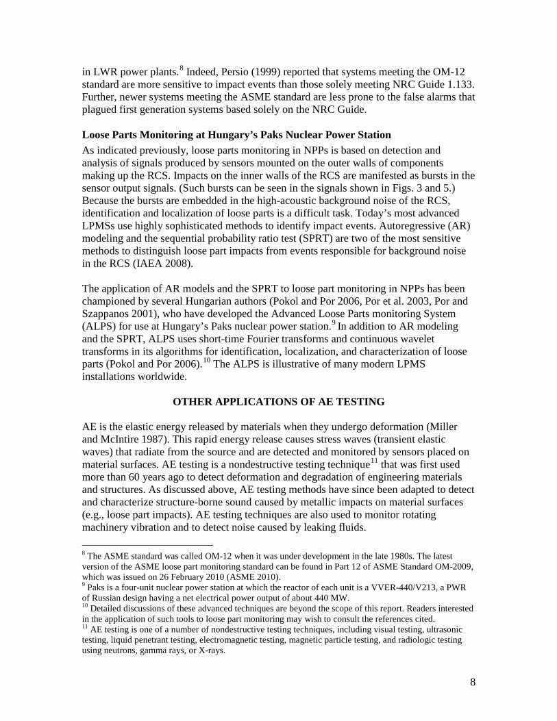
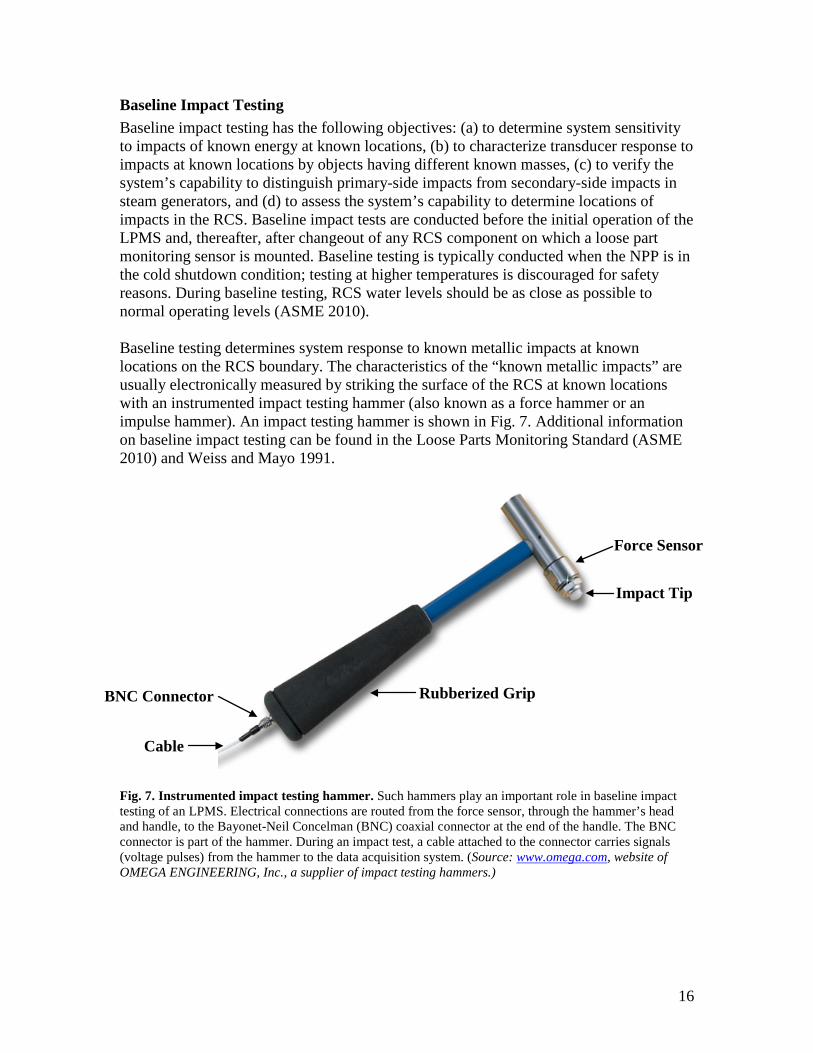
Baseline impact testing has the following objectives: (a) to determine system sensitivity to impacts of known energy at known locations, (b) to characterize transducer response to impacts at known locations by objects having different known masses, (c) to verify the system’s capability to distinguish primary-side impacts from secondary-side impacts in steam generators, and (d) to assess the system’s capability to determine locations of impacts in the RCS. Baseline impact tests are conducted before the initial operation of the LPMS and, thereafter, after changeout of any RCS component on which a loose part monitoring sensor is mounted. Baseline testing is typically conducted when the NPP is in the cold shutdown condition; testing at higher temperatures is discouraged for safety reasons. During baseline testing, RCS water levels should be as close as possible to normal operating levels (ASME 2010). Baseline testing determines system response to known metallic impacts at known locations on the RCS boundary. The characteristics of the “known metallic impacts” are usually electronically measured by striking the surface of the RCS at known locations with an instrumented impact testing hammer (also known as a force hammer or an impulse hammer). An impact testing hammer is shown in Fig. 7. Additional information on baseline impact testing can be found in the Loose Parts Monitoring Standard (ASME 2010) and Weiss and Mayo 1991.
Fig. 7. Instrumented impact testing hammer. Such hammers play an important role in baseline impact testing of an LPMS. Electrical connections are routed from the force sensor, through the hammer’s head and handle, to the Bayonet-Neil Concelman (BNC) coaxial connector at the end of the handle. The BNC connector is part of the hammer. During an impact test, a cable attached to the connector carries signals (voltage pulses) from the hammer to the data acquisition system. (Source: www.omega.com, website of OMEGA ENGINEERING, Inc., a supplier of impact testing hammers.)
Impact Tip
Force Sensor
Rubberized Grip
BNC Connector
Cable

17
SUPPLIERS OF LPMS EQUIPMENT, SOFTWARE, AND SERVICES (1) Analysis and Measurement Services Corporation (AMS), AMS Technology Center, 9119 Cross Park Drive, Knoxville, Tennessee 37923 USA (http://amscorp.info)
The AMS website states, “Using signals from existing accelerometers in nuclear power plants, the loose parts monitoring system from AMS determines the location and mass of any significant loose parts within the reactor coolant system.” “AMS builds its loose parts monitoring systems per order using the latest components and software products and can add such capabilities as core barrel vibration measurements and other features to its loose parts monitoring system.” (2) AREVA NP – Paris La Defense, France (www.areva-diagnostics.de/en/)
According to their website, AREVA NP provides LPMSs that feature an on-demand digital recorder and analysis capability with an analog front end. It enables the upgrade of digital features without the hassle of redesign. Sensor signals are input to the analog signal module, which also provides power to the remote charge converter. The input signal to the computer is separated into two signals: one signal is band-pass filtered and is used for analysis, and the second is a wide-band signal. Moreover, two alarm circuits preclude false alarms. The wide-band signal evaluates the sensor’s condition to protect against a faulty or failed accelerometer or remote charge converter. The data acquisition method captures the first event and eliminates the need for a first-event recorder. As subsequent alarms occur, they are analyzed and stored on a hard disk. In the normal scan mode, a time window of 100 ms is continuously monitored. The website of Areva Inc. (Areva in North America: http://us.areva.com) states, “As energy suppliers invest substantially in major components to enhance the long-term performance of their utilities, AREVA provides an innovative and cost effective solution to protect major component assets. Our Loose Parts Monitoring System (LPMS) combines a highly successful track record of field proven technical performance and reliability with the industry’s most responsive service teams to help keep your plant components operating safely and efficiently. LPMS can give you piece of mind to quickly identify loose parts issues that can interfere with the output of your plant.” (3) Babcock-Hitachi K.K., Akihabara UDX Building 14-1, Sotokanda 4-chome Chiyoda-ku,Tokyo, 101-0021 Japan (www.bhk.co.jp/english/energy/nuclear/index.html)
The website identified above lists an LPMS as a Babcock-Hitachi product and displays photographs showing the control cabinet and its display screen (similar to Fig. 3), but text describing the LPMS is not provided. (4) Envirocoustics S.A. El. Venizelou 7 & Delfon, 14452 Metamorphosis, Athens, Greece. (www.envirocoustics.gr)
Enviroacoustics S.A. is affiliated with Physical Acoustics Corporation (listed below). According to the website, Enviroacoustics products include AE equipment and systems, software for AE signals, and LPMS software. Enviroacoustics, Euro Physical Acoustics

18
in France (listed immediately below), and Physical Acoustics Corporation in the USA are members of the Mistras Group Inc. (www.mistrasgroup.com). (5) Euro Physical Acoustics, 27 Rue Magellan, ZAC des Portes de Sucy, F94370, Sucy en Brie, Paris, France (www.epandt.com)
Euro Physical Acoustics is affiliated with Physical Acoustics Corporation (listed below). According to the website, Euro Physical Acoustics products include AE equipment and systems, software for AE signals, and LPMS equipment and software. Euro Physical Acoustics, Enviroacoustics in Greece (listed above), and Physical Acoustics Corporation in the USA are members of the Mistras Group Inc. (www.mistrasgroup.com). (6) Kinectrics, Inc., 800 Kipling Avenue, Unit 2, Toronto, Ontario, M8Z, Canada (www.kinectrics.com)
According to their website, Kinectrics specializes in developing and applying remotely operated computer-controlled inspection and nondestructive evaluation (NDE) systems for all types of materials and surfaces. Kinectrics NDE systems are ideal for the detection, quantification and three-dimensional display of cracks, frets, scratches, wall loss, corrosion pits, laminar flaws, and erosion. An industry leader in inspection and NDE, Kinectrics has successfully designed several innovative and proven products and services for one of North America’s largest utilities. (7) Laborelec Inc., Rodestraat 125, 1630, Linkebeek, Belgium (www.laborelec.com)
The Laborelec website states, “Laborelec is a leading research and competence centre in electrical power technology. It was established in 1962 in order to support Belgian electricity companies with research, development, and specialized services. Today, it is part of GDF SUEZ, a world leader in energy. [Laborelec’s] competences cover the entire electricity value chain: generation, transmission and distribution, and end-use. Specialized research and services are offered in each of these domains, to companies in all parts of the world. Headquarters are located near Brussels, and branch offices are located in the Netherlands and Germany.” The website makes several references to LPMS but does not explicitly state that Laborelec manufactures and sells LPMSs. (8) Pakistan Atomic Energy Commission (PAEC), Islamabad, Pakistan (www.paec.gov.pk/news-archive-pakatom/detail/detail-2011/p-so11-news2.htm)
According to the website identified on the line above, the PAEC Directorate of Nuclear Power Engineering-Reactor has “developed nuclear engineering systems and equipment for surveillance monitoring of reactor core and pressure boundary, plant safety, and operational core physics testing in nuclear power plants.” PAEC states that these systems “have been used in operating NPPs/nuclear reactors.” Systems and equipment that have been developed by PAEC are presented in a bulleted list, which is quoted below:
• “Loose Parts Monitoring System, • Reactor Internals Vibration Monitoring System, • Thermal Fatigue Monitoring System,

19
• Plant Reactivity Meter, • Reactor Control Simulator, • Criticality & Control Rod Worth Measuring Devices • Core Kinetic & Dynamic Testing, • Fuel Burn up Measurement System, and • Central Machine Condition Monitoring System (under development).”
PAEC closes the website’s introduction to these systems and equipment with these remarks: “These systems/devices are not available from foreign vendors due to export restrictions. Their development would help in NPP indigenization, besides resulting in considerable cost savings.” (Bold font added for emphasis by the authors.) The PAEC website continues with short descriptions of the items listed in the first, second, and fourth bullets above. The LPMS description is quoted in the following paragraph. “LPMS is an essential device for integrity monitoring of reactor in PWR plants under ASME-OM-12, RG-1.133, PAK/911 standards. The indigenized LPMS detects trapped loose parts in reactor components and determines their location, mass and energy with the help of sixteen acoustic sensors. System software is very complex and special routines of acoustic emission & signal processing have been written to improve system performance. Indigenized LPMS was installed in C-1 by NPER engineers in RFO-6…. It was qualified by in-situ testing and approved by PNRA. During one year operation at C-1, the LPMS has performed its designed functions.”15 (9) Physical Acoustics Corporation (PAC), 195 Clarksville Rd., Princeton, New Jersey 08550 USA (www.pacndt.com)
According to its website, PAC designs and manufactures AE sensors and AE measurement systems, including LPMSs. In 1978, PAC was founded in Princeton, New Jersey, by a Bell Labs scientist, Dr. Sotirios J. Vahaviolos, and two venture capitalists, Frederick Adler (VENAD) and Milton Pappas (Euclid Partners). PAC is now a member of the Mistras Group Inc. (www.mistrasgroup.com). AE instrumentation supplied by PAC typically consists of:
• An AE sensor that converts a stress (sound) wave to an electrical signal, • A low noise amplifier that raises the signal to a usable level, • Signal processing electronics for feature extraction and waveform capture, and • Microprocessor and digital signal processor (DSP)-based parallel distributing
processing instrumentation,
15 Notes: RG 1.133 is a reference to Regulatory Guide 1.133 of the U.S. NRC. PAK/911 is Pakistan’s “Regulation on the Safety of Nuclear Power Plants – Design.” C-1 is shorthand for Pakistan’s Chasma Nuclear Power Plant Unit 1, which has a net electrical power rating of 300 MW; its nuclear steam supply system has a two-loop PWR furnished by China National Nuclear Corporation (CNNC). C-1 construction began in 1993, and the plant began commercial operation in 2000. The LPMS was installed in C-1 during the 6th reactor fueling outage (RFO-6), which took place from April to June, 2010. NPER is PAEC’s Directorate of Nuclear Power Engineering-Reactor; PNRA is the Pakistan Nuclear Regulatory Authority.
20
• Knowledge-based software for easy analysis, defect correlation and development of expert systems that comply with demanding AE standards, and
• Decision and feedback electronics to utilize the information.
(10) Samchang Co. Ltd.,#168-9, Shin Jung 3 - Dong Nam-Gu, Ulsan, South Korea (www.samchang.com) Samchang Co. staff members and coauthors from the Korea Atomic Energy Research Institute have written papers on LPMS technology, and the Samchang website lists “development of loose part monitoring system” as an “ongoing and planning project.” (11) Technology for Energy Corporation (TEC), Nuclear Division, 10737 Lexington Drive, Knoxville, Tennessee 37932-3294, USA (www.tecnuclear.com)
According to their website, products of the TEC Nuclear Division are designed, manufactured, and distributed from the employee-owned parent company, TEC (www.tec-usa.com), based in Knoxville, TN. Nuclear products include the TEC Model 1414 Acoustic Valve Flow Indication System and the TEC Model 1430 Loose Part Monitoring System. The Model 1414 valve flow monitor uses AE monitoring techniques to provide a reliable indication of the flow through safety and relief valves in nuclear power plant valves so that the operator knows when there is a path open for loss of coolant. This method of valve surveillance satisfies the requirements of NRC Regulatory Guide 1.97 (Dec. 1980). Customers who have purchased Model 1414 systems include more than two dozen U.S. electric utilities and three foreign utilities. The TEC website describes the Model 1430 LPMS as a state-of-the-art acoustic detection, analog processing, and annunciation system that meets the requirements of NRC Regulatory Guide 1.133. LPMSs manufactured by TEC have been installed at the following NPPs:
• Waterford – Unit 3 (PWR), operated by Entergy Operations, Inc.; • Turkey Point – Units 3 and 4 (PWR), operated by Florida Light and Power Co.; • Main Yankee – (PWR, no longer in operation); • Seabrook – Unit 1 (PWR), operated by NextEra® Energy Resources; • Sequoyah – Units 1 and 2 (PWR), operated by Tennessee Valley Authority; • Watts Bar – Unit 1 (PWR), operated by Tennessee Valley Authority; and • Columbia – Unit 2 (BWR), operated by Energy Northwest.
(12) Meggitt SA, Rte de Moncor 4, P.O. Box 1071, CH 1616 Fribourg, Switzerland (www.vibro-meter.com)
Vibro-Meter is a wholly owned subsidiary of Meggitt PLC, a multi-national high-tech manufacturing company (www.meggitt.com.). According to the company’s website, Vibro-Meter SA is “a world leader in the design and manufacture of vibration monitoring systems for propulsion units and machinery used in commercial aircraft, helicopters, military, aerospace, industrial, and marine installations. Vibro-Meter SA also provides instrumentation for rocket engines and nuclear applications.”
21
“Since 1978, Vibro-Meter's nuclear systems have been used for many applications including … loose parts monitoring, reactor internals vibration monitoring, fuel pin flow induced vibration, steam generator and in-core fuel flow induced vibration programs…. Vibro-Meter offers unique piezoelectric transducers for operation inside the primary circuit of nuclear reactors (AGR, PWR, BWR, ABWR, VVER, APWR).”
• “Accelerometers and dynamic pressure transducers with front end electronics for startup and hot functional tests. They are capable of operating long term inside the primary circuit.
• Loose parts monitoring accelerometers with more than 20 years reliability demonstration.
• Dynamic pressure transducers for permanent operation in primary circuit of nuclear reactors.
• Miniature biaxial accelerometer for fuel in core vibration measurement (neutron detector location).
• Qualification NRC Guide 1.133, 1.20, DIN 25.475.”
The Vibro-Meter website also includes an interesting list of nuclear milestones covering “more than 30 years experience in supplying high reliability instrumentation to reactor operators worldwide.” A partial list of the nuclear milestones is presented below:
1972 First successful characterization of the piezoelectric accelerometer CA901 at 580°C (1,076°F) by Electricité de France, Les Renardières. [The CA901 transducer is a radiation-hardened device that is rated for continuous operation at temperatures up to 650°C.]
1982–2001 Various start up and hot functional testing instrumentation for AGR, PWR, BWR, and VVER worldwide.
1982–2008 Siemens qualified the Loose Parts Monitoring Accelerometer (CA901) for their monitoring systems (NRC Guide 1.133 or DIN 25.475).
1991 LPMS and Reactor Internals Vibration Monitoring System with CA952 and AE sensors (AT150) delivered to Framatome for Guangdong.
1996 LPMS (with new CA164 accelerometers) retrofitted the Westinghouse PWRs at Beznau, Switzerland.
1997 Qualification program for the CA962 accelerometer for Reactor Internal Vibration Monitoring of VVER by Skoda/Westinghouse for Temelin.
1998 Framatome ANP (Siemens) evaluated the CA962 accelerometer with IPC629 and GSI130 electronics for Reactor Internal Vibration Monitoring for the EPR.
2007 GE ESBWR selected transducers for primary circuit Flow Induced Vibration Program: Dynamic pressure transducers CP 104 M601 and CP 211 M072, accelerometer CA 901 M511 with cables and remote charge converters IPC 629, and galvanic separation module GSI 130.
2008 AREVA for EPR Olkiluoto 3, Finland Accelerometer CA 952 for secondary piping system vibration measurement and Loose Parts Monitoring Accelerometer CA901.
22
2008 Trillo 1 PWR Spain: Accelerometer CA 901, CA 962 with electronics IPC629 and GSI 130 and VM600; loose parts monitoring and reactor internals vibration monitoring. (13) VUJE a. s., Okruzna 5, 918 64 Trnava, Slovak Republic (www.vuje.sk/en/index.php)
According to this Slovakian company’s website, “VUJE a.s. is an engineering company that performs design, supply, implementation, research, and training activities, particularly in the field of nuclear and conventional power generation.” “VUJE was established in 1977 as a state research institute; in 1994, it was transformed into a joint stock company whose shares are owned by company employees and former employees. The change from the state-owned company into a 100% private company meant also a change in company operations, i.e. a change from an originally research organisation into an engineering company that presently implements large projects mainly in the field of nuclear power generation. ... [These] projects are performed by the company as turnkey projects, i.e. the projects are implemented starting with the development of design documents up to the performance of commissioning tests.” An electronic search of the VUJE website yielded no hits explicitly related to LPMS, but a 2005 technical paper by two VUJE employees (Figedy and Oksa 2005) states, “VUJE, Inc. has more than 15 years of experience with the LPMS of its own production. Our systems are installed at nuclear power plants in Slovakia. Czech Republic, and China (in cooperation with Westinghouse Electric Company, USA).” (14) Westinghouse Electric Company LLC, Box 355, Pittsburgh, Pennsylvania 15230, USA (www.westinghousenuclear.com)
Westinghouse manufactures and markets an LPMS called the DMIMS-DX™ Digital Metal Impact Monitoring System, which is pictured in Figs. 2 and 3. Many DMIMS-DX™ systems are currently in operation. A newer design developed for the Westinghouse AP1000 reactor is currently being marketed. (15) WOORI Technology, Inc., wooriTG. Bldg., 1595-1, Bongchun7-dong, Gwanak-gu, Seoul 151-835, South Korea (http://wooritg.en.ec21.com/LPMS_Loose_Part_Monitoring_System--15403_15443.html)
The WOORI website identified above provides the following product overview: “LPMS is a monitoring device that detects the shock wave generated from the collision of loose parts and pressure limitation internal structure by mounting accelerometer (shock wave sensitive sensor), where loose parts gather naturally.” “The metal loose parts inserted from outside of nuclear power RCS and generated internally within the system travels the inside of structure along with high-speed coolant could cause a critical damage to the inner structure of RCS.”
23
“This system judges the risk and confirms the existence of these loose parts by assessing risk of RCS's internal structure damage and breakdown of power plant for economical and safe operation of the power plant.” “LPMS can prevent accidents such as damage of reactor coolant system and structure, rod operation hindrance, and steam generator tube leakage; hence, an important system for higher power plant safety insurance.” WOORI LPMS have been installed in eight units at three NPPs operated by Korea Hydro & Nuclear Power Co., Ltd. These plants and units are listed below:
• Younggwang – Units 1 and 2 (PWR, LPMS installation in 1997), • Kori – Units 3 and 4 (PWR, LPMS installation in 1999), • Kori – Units 1 and 2 (PWR, LPMS installation in 2001), and • Ulchin – Units 1 and 2 (PWR, LPMS installation in 2001).
CONTROLS ON LPMS EXPORTS FROM THE UNITED STATES
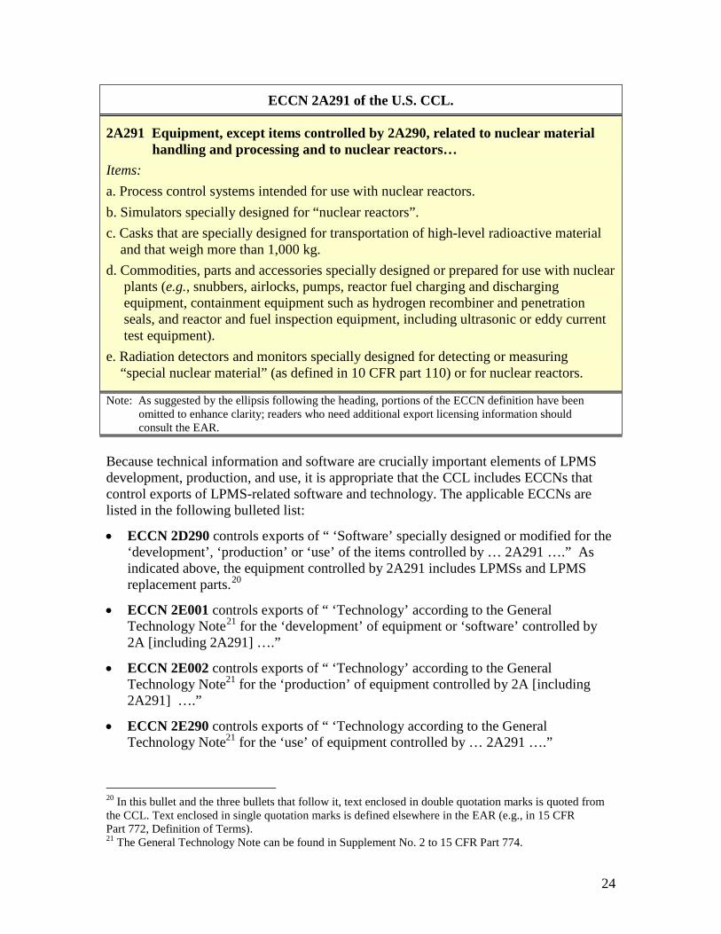
In the United States, the Bureau of Industry and Security (BIS), an agency of the Department of Commerce (DOC), is responsible for implementing and enforcing the U.S. Export Administration Regulations (EAR),16 which regulate the export and re-export of most commercial items. Specific items (e.g., machine tools, lasers, carbon fiber) that fall under the export control jurisdiction of the BIS are listed in the Commerce Control List (CCL), which is included in the EAR.17 Items listed in the CCL are identified by an Export Control Classification Number (ECCN). According to BIS, ECCN 2A291 controls the export an LPMS intended for NPP service.18 The textbox on the following page presents the export control language of ECCN 2A291. Although ECCN 2A291 does not explicitly list LPMSs as controlled items, the definition of items controlled by ECCN 2A291.d is sufficiently broad to capture LPMS exports. ECCN 2A291.d covers LPMS replacement parts, including (1) accelerometers with integrated cables, (2) junction boxes with charge preamplifiers and cables, (3) power supplies for charge preamplifiers, and (4) additional cables. Some items, such as impact testing hammers (Fig. 7), which support the installation and use of an LPMS but are not actually part of the LPMS, may be exported with LPMS replacement parts and may be classified as EAR 99.19
16 The EAR are regulations set forth in Parts 730–774, inclusive, of Title 15 of the U.S. Code of Federal Regulations (CFR). 17 The CCL can be found in Supplement No. 1 to 15 CFR Part 774. 18 Steven Clagett – email message to D.W. Langenberg, November 14, 2012. 19 Items designated EAR99 are subject to the EAR but are not listed in the CCL and do not have an ECCN.
24
ECCN 2A291 of the U.S. CCL.
2A291 Equipment, except items controlled by 2A290, related to nuclear material handling and processing and to nuclear reactors… Items: a. Process control systems intended for use with nuclear reactors. b. Simulators specially designed for “nuclear reactors”. c. Casks that are specially designed for transportation of high-level radioactive material and that weigh more than 1,000 kg. d. Commodities, parts and accessories specially designed or prepared for use with nuclear plants (e.g., snubbers, airlocks, pumps, reactor fuel charging and discharging equipment, containment equipment such as hydrogen recombiner and penetration seals, and reactor and fuel inspection equipment, including ultrasonic or eddy current test equipment). e. Radiation detectors and monitors specially designed for detecting or measuring “special nuclear material” (as defined in 10 CFR part 110) or for nuclear reactors.
Note: As suggested by the ellipsis following the heading, portions of the ECCN definition have been omitted to enhance clarity; readers who need additional export licensing information should consult the EAR. Because technical information and software are crucially important elements of LPMS development, production, and use, it is appropriate that the CCL includes ECCNs that control exports of LPMS-related software and technology. The applicable ECCNs are listed in the following bulleted list:
• ECCN 2D290 controls exports of “ ‘Software’ specially designed or modified for the ‘development’, ‘production’ or ‘use’ of the items controlled by … 2A291 ….” As indicated above, the equipment controlled by 2A291 includes LPMSs and LPMS replacement parts.20
• ECCN 2E001 controls exports of “ ‘Technology’ according to the General Technology Note21 for the ‘development’ of equipment or ‘software’ controlled by 2A [including 2A291] ….”
• ECCN 2E002 controls exports of “ ‘Technology’ according to the General Technology Note21 for the ‘production’ of equipment controlled by 2A [including 2A291] ….”
• ECCN 2E290 controls exports of “ ‘Technology according to the General Technology Note21 for the ‘use’ of equipment controlled by … 2A291 ….”
20 In this bullet and the three bullets that follow it, text enclosed in double quotation marks is quoted from the CCL. Text enclosed in single quotation marks is defined elsewhere in the EAR (e.g., in 15 CFR Part 772, Definition of Terms). 21 The General Technology Note can be found in Supplement No. 2 to 15 CFR Part 774.
25
It is important to note that exports of LPMS equipment (ECCN 2A291), software (2D290), and technology (2E001, 2E002, and 2E290) are controlled for nuclear nonproliferation (NP) and antiterrorism (AT) reasons. A license is required to export these items to countries for which an “X” appears in NP Column 2 or AT Column 1 of the Commerce Country Chart (CCC).22 Only Iraq, Israel, Libya, and Pakistan currently meet the NP Column 2 requirement, and only Sudan currently meets the AT Column 1 requirement.23
22 The CCC can be found in Supplement No. 1 to 15 CFR Part 738. 23 CCC references in this paragraph were derived from the Electronic Code of Federal Regulation (http://ecfr.gpoaccess.gov/), which was current as of 23 November 2012.
26
REFERENCES American Society of Mechanical Engineers (ASME). 2010. “Loose Part Monitoring in Light-Water Reactor Power Plants,” Part 12 of Operation and Maintenance of Nuclear Power Plants, ASME OM-2009, an American National Standard, ASME International, pp. 128–145. American Society of Mechanical Engineers (ASME). 2011. 2010 ASME Boiler and Pressure Vessel Code (2011a Addenda), Part V, Nondestructive Evaluation, ASME International. American Society for Testing and Materials (ASTM). 2007. “Standard Practice for Leak Detection and Location Using Surface-Mounted Acoustic Emission Sensors,” ASTM E 1211-07, ASTM International. American Society for Testing and Materials (ASTM). 2011. “Standard Terminology for Nondestructive Examinations.” ASTM E 1316-11a, ASTM International. Babcock & Wilcox. 1992. Steam: Its Generation and Use, 40th edition. The Babcock & Wilcox Company. Benz, A. E. G. 1998. “Use of Acoustic Emission Techniques for Detection of Discontinuities,” Materials Evaluations, pp. 1215–1222. Chan, R. W. Y., D. R. Hay, J. R. Hay, and H. B. Patel. 1989. “Improving Acoustic Emission Crack /Leak Detection in Pressurized Piping by Pattern Recognition Techniques,” Nondestructive Testing, Vol. 1, Proceedings of the 12th World Conference, Amsterdam, The Netherlands, pp. 851–853. Chang, Y. W., J.-C. Jung, and P.-H. Seong. 2004. “Algorithm Automation for Nuclear Power Plant Loose Parts Monitoring System,” Nuclear Engineering and Design, 231, pp. 99–107. Figedy, Stefan and Gabriel Oksa. 2005. “Modern Methods of Signal Processing in the Loose Part Monitoring System.” Progress in Nuclear Energy, Vol. 46, Nos. 3–4, pp. 253–267. Fowler, T. J. “Acoustic Emission Testing in Vessels and Piping.” 1987. Chemical Engineering Progress, 85(5), pp. 25–32. Hartman, W. F. and J. W. McElroy, eds. 1979. “Acoustic Emission Surveillance of Boiling Water Reactor Piping Nozzles and Valves,” Acoustic Emission Monitoring of Pressurized Systems Valve Surveillance, ASTM STP697, American Society for Testing and Materials, p. 207.
27
Haynes, H. D. 1990. “Recent Improvements in Check Valve Monitoring Methods,” Eighteenth Water Reactor Safety Meeting, Volume 3, Pressure Vessel Integrity; Piping and NDE; Aging and Compounds, Rockville, MD, pp. 403–429. International Atomic Energy Agency (IAEA). 2008. On-Line Monitoring for Improving Performance of Nuclear Power Plants, Part 2: Process and Component Condition Monitoring and Diagnostics, IAEA Nuclear Energy Series No. NP-T-1.2. IAEA. Vienna. International Atomic Energy Agency (IAEA). 2011. Nuclear Power Reactors in the World – 2011 Edition, IAEA Reference Data Series No. 2. IAEA. Vienna. International Electrotechnical Commission (IEC). 2009. Nuclear Power Plants – Instrumentation Important to Safety – Acoustic Monitoring Systems for Detection of Loose Parts: Characteristics, Design Criteria and Operational Procedures, Standard IEC 60988, Edition 2.0, IEC, Geneva. Kenny, James M. (Chairman, BWR Owners’ Group). 2010. Letter to Mr. Robert Pulsifer (NRC), Subject: BWR Owners’ Group Licensing Topical Report NEDC-32975P, “Regulatory Relaxation for BWR Loose Parts Monitoring Systems,” BWROG-00075. Keyvan, S. and R. King. 1992. “The Role of Acoustic Monitoring as Diagnostic Tools in Nuclear Reactors,” Journal of Acoustic Emission, 10 (3/4), pp. 91–96. Kryter, R. C. 1977. “Loose parts monitoring: Present status of the technology, its implementation in U.S. reactors and some recommendations for achieving improved performance,” Progress in Nuclear Energy, Vol. 1, Nos. 2–4, pp. 667–672. Kryter, R. C. 1984. “Loose Part Monitoring Programs and Recent Operational Experience in Selected U.S. and Western-European Commercial Nuclear Power Stations,” U.S. NRC, NUREG/CR-3687, Washington D.C. Kupperman, D. S. 1993. “Considering Options for Leak Detection,” Nuclear Engineering International, pp. 41–42. Lees, F. P. (1996). Loss Prevention in the Process Industries (2nd Edition), Elsevier. Mayo, C. W. et al. 1988. “Loose-Parts Monitoring System Improvements,” EPRI NP-5743, Electric Power Research Institute (EPRI), Palo Alto, CA. Mayo. C. W. and H. G. Shugars. 1988. “Loose Part Monitoring System Improvements,” Progress in Nuclear Energy in Great Britain, 21, p. 505. Michel, B. and C. Puyal. 1988. “Operational and Economical Experience with Vibration and Loose Parts Monitoring Systems on Primary Circuits of PWRs,” Progress in Nuclear Energy, 21, pp. 469–473.
28
Miller, R. K. and P. McIntire, eds. 1987. Nondestructive Testing Handbook, 2nd edition, Volume 5, “Acoustic Emission Testing,” American Society for Nondestructive Testing (ASNT). Miller, Ronnie K. and Eric V. K. Hill (technical editors), and Patrick O. Moore (editor). 2005. Nondestructive Testing Handbook, 3rd edition, Volume 6, “Acoustic Emission Testing,” American Society for Nondestructive Testing (ASNT). Nakamura, T. and M. Terda. 1985. “Development of Leak Monitoring System for Pressurizer Valves,” Progress in Nuclear Energy, 15, pp. 175–179. Olma, B. J. 2003. “Experience with Identification of Loose Parts by Acoustic Monitoring of Primary System,” Progress in Nuclear Energy, 43, pp. 225–232. Patel, H. B. and A. W. Cook. 1989. “Acoustic Emission Leak Monitoring in Pressurized Piping,” Nondestructive Testing, Proceedings of the 12th World Conference, Amsterdam, The Netherlands, pp. 1116–1118. Persio, J. V. 1999. “Commercial Nuclear Reactor Loose Part Monitor Set-points,” Progress in Nuclear Energy, 34 (3), pp. 203–211. Pokol, G. and G. Por. 2006. “The Advanced Loose Parts Monitoring System (ALPS) and Wavelet Analysis,” International Journal of Nuclear Energy Science and Technology,” 2 (3), pp. 241–-252. Por., G., J. Kiss, I. Sorosanszky, and G. Szappanos. 2001. “Development of a False Alarm Free, Advanced Loose Parts Monitoring System (ALPS),” Progress in Nuclear Energy, 43, No. 1–4, pp. 243–251. Por, G. and G. Szappanos. 2001. “ALPS, Advanced Loose Parts System for Paks NPP,” International Conference on Nuclear Energy in Central Europe 2001, held in Portorož, Slovenia. Rhodes, W. D., R. V. Furstenau, and H. A. Larson. 2000. “Experimental Breeder Reactor-II Frequency Response Test Measurements via Pseudorandom, Discrete-Level Binary and Ternary Signals,” Nuclear Technology, 130, pp. 145–158. Tsunoda, T., S. Kenich, and H. Nanba. 1985. “The Development of a BWR Main Stream Safety/Relief Valve Monitoring Systems,” Progress in Nuclear Energy, 15, pp. 191–198. U.S. Nuclear Regulatory Commission (NRC). 1981. “Loose-Part Detection Program for the Primary System of Light-Water Cooled Reactors,” Regulatory Guide 1.133, Rev. 1, Washington D.C. Weiss, J. M. and C. W. Mayo. 1991. “Recommendations for Effective Loose Parts Monitoring,” Nuclear Engineering and Design, 129, pp. 121–127.