Embed Size (px)
Citation preview
1
ExProtect c©
A software response to important questionson safety in dust and gas explosions
Dirk Lorenz
Research Centre for Applied System Safety and Industrial Medicine
Mannheim, Germany
Abstract
ExProtect is an expandable software-package under Windows 3.1/3.11 resp. Windows
95/NT containing the programs SIMEK, STS, VENT and AD-formula.
SIMEK was created on the basis of extensive experimental investigations to give answers on
the required thickness of fastenings (hinges resp. ropes) and the demanded size of explosion
doors and explosion lids for dust-explosion endangered containers and buildings. By using
expanded versions of the VDI 3673 guidline-formula for reduced pressure and the cubic law,
SIMEK estimates the time-pressure curve of a dust explosion in the considered container.
With this, SIMEK solves the equation of motion for explosion doors or explosion lids nu-
merically and simultaneously the searched for values of fastening-thickness is derived.
STS is used to find out how far the debris of bursting containers or buildings will be cata-
pulted after a dust explosion. With a few data about the considered building and burnable
dust STS finds the initial velocity of a fragment by using the equation of Gurney. The fol-
lowing calculation of the fragments trajectory is done numerically. Computed and in praxis
observed distances of flying debris after dust explosions are in satisfactory agreement.
If suitable vent areas for explosion endangered rooms or containers are searched for, VENT
will give the answers. The calculations of VENT are correct for pressure relief devices with-
out any mass inertia. The computer-code of VENT uses formulas of well-known guidelines
and publications. Furthermore it contains some additional tools, which are the result of
extensive experimental research.
AD-formula is a program to answer questions about the stability of containers standing
under pressure and is based on the corresponding AD-instructions.
2 1 INTRODUCTION
1 Introduction
In practice, primitive pressure relief devices are in use which most of the times can prevent
the container from bursting but are dangerous for the immediate environment in case of an
explosion. Such relief devices often consist of one or several metal or concrete panels that
are tied to the container with ropes or chains. If an explosion occurs, these ropes or chains
are in most cases too weak to hold the relief devices in place; they will break and the relief
devices will be catapulted away.
A grave accident in recent times gave the impulse for experimental research in order to be
able to define the forces on those ropes in the event of a pressure relief. In Kappelrodeck
(Black Forest), where an experimental plant of the FSA is situated, a series of experiments
was done with explosion lids of different masses on a 1 m3-vessel, using different explosion
parameters [1]. The explosion lids were tied to the vessel with steelropes, connected to a
force measuring device which made it possible to measure directly as a function of time
the force put on the explosion lid by the safety-ropes when the ropes abruptly stopped the
catapulted lid during the explosion. Forces of up to some 100 kN were ascertained.
Later, the project was expanded to the testing of explosion doors. On a 9.4 m3-vessel,
explosion doors of different masses were exposed to the effect of light to heavy dust explo-
sions. With the help of an incremental encoder the opening angle of the explosion door was
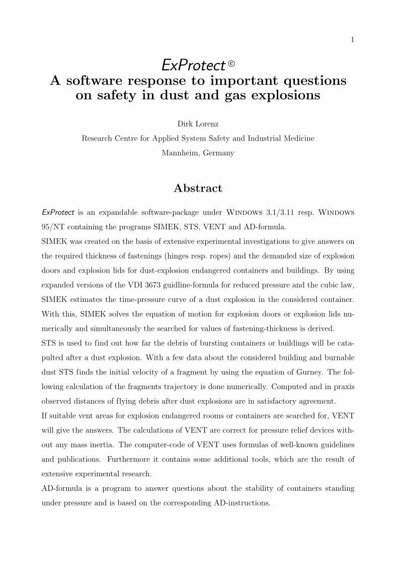
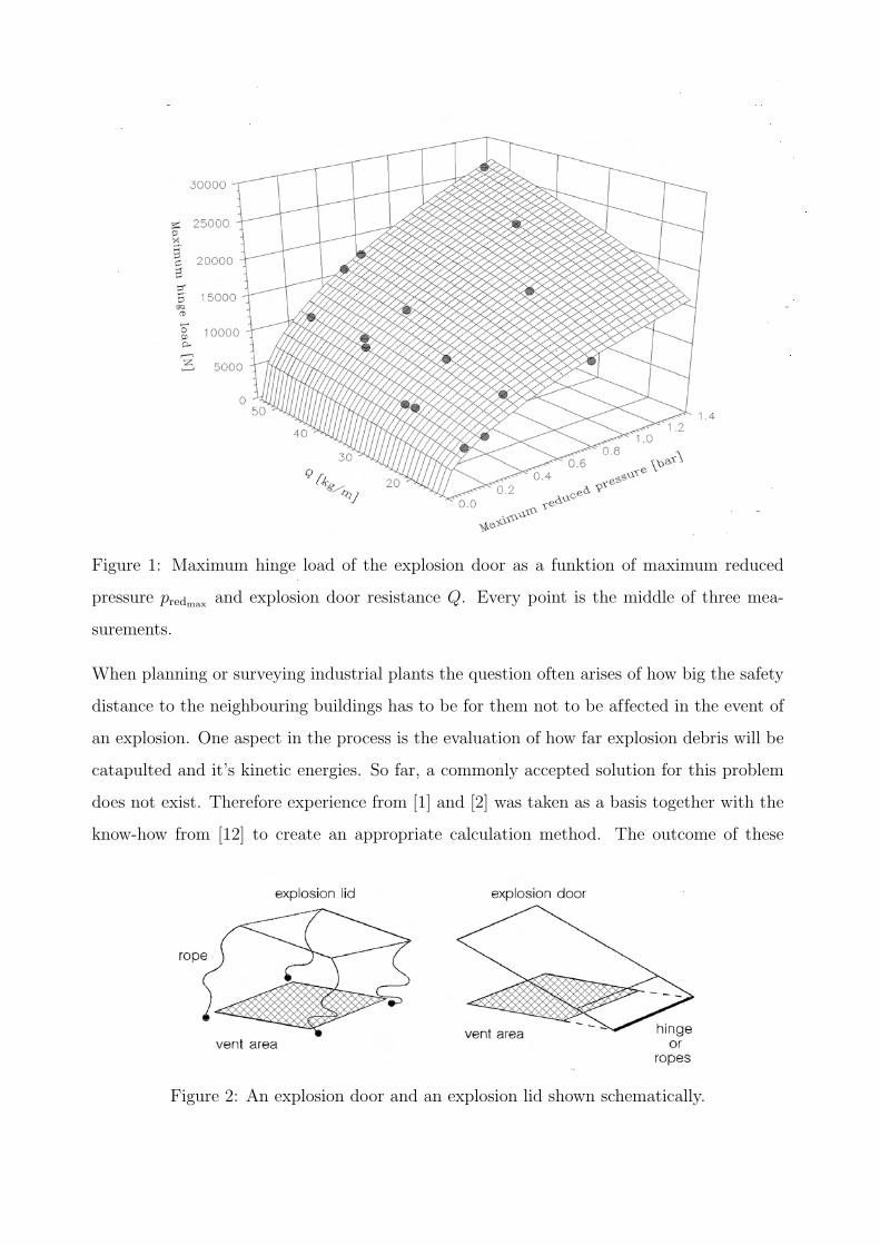
recorded as a function of time. The test results gave access to all desired factors. Figure 1
shows for example the maximum force on the explosion door’s hinge as a function of max-
imum reduced pressure predmax and explosion door resistance Q. As a consequence to the
experiments a vast study was initiated that deals with the mechanics of explosion doors and
explosion lids on a theoretical and an experimental basis, including data from experiments
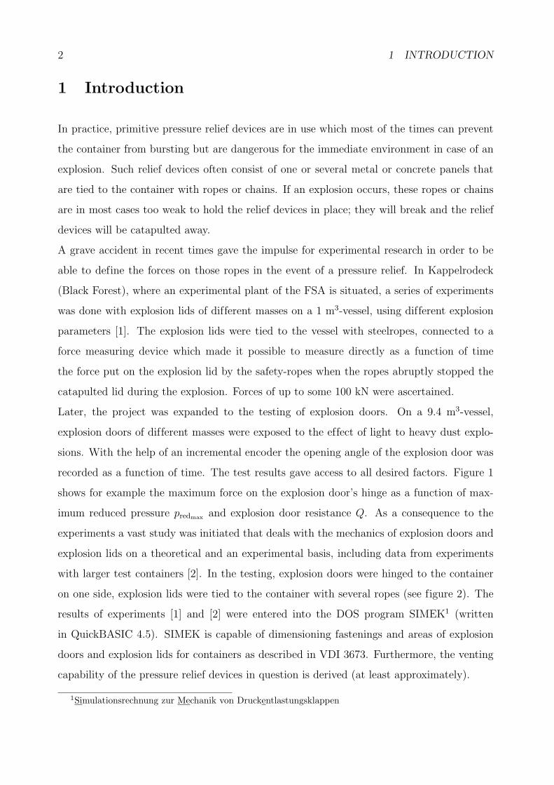
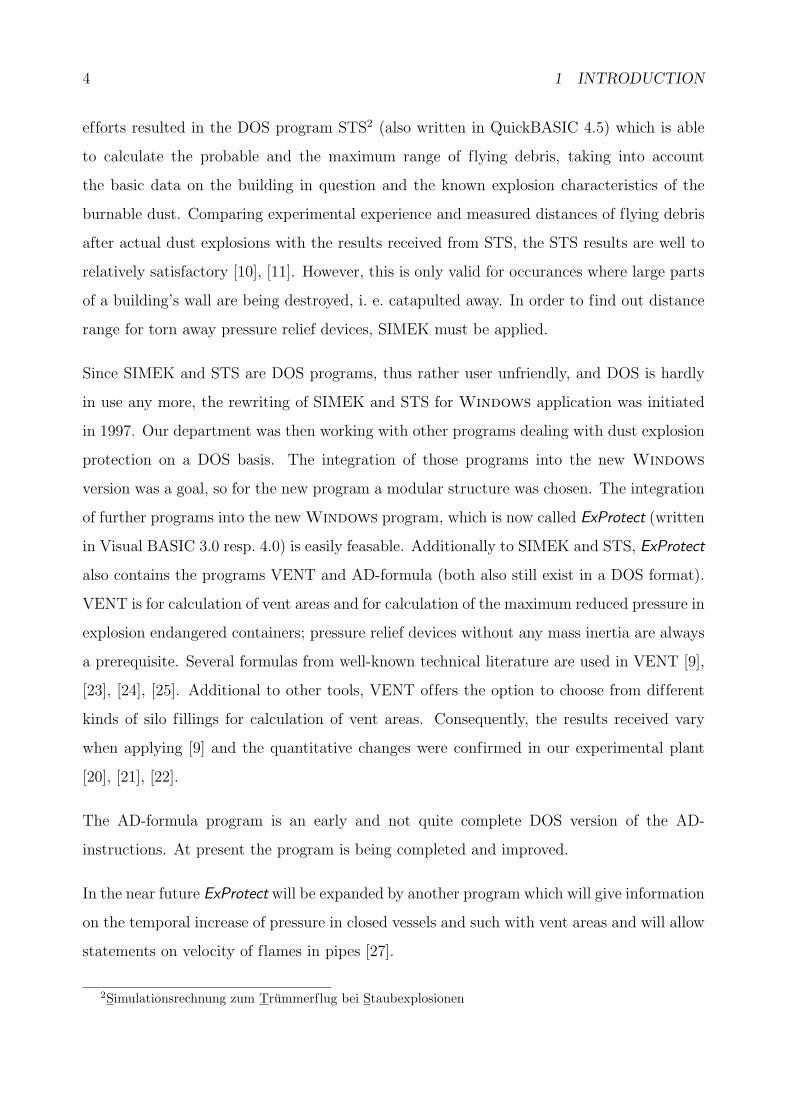
with larger test containers [2]. In the testing, explosion doors were hinged to the container
on one side, explosion lids were tied to the container with several ropes (see figure 2). The
results of experiments [1] and [2] were entered into the DOS program SIMEK1 (written
in QuickBASIC 4.5). SIMEK is capable of dimensioning fastenings and areas of explosion
doors and explosion lids for containers as described in VDI 3673. Furthermore, the venting
capability of the pressure relief devices in question is derived (at least approximately).
1Simulationsrechnung zur Mechanik von Druckentlastungsklappen
3
Figure 1: Maximum hinge load of the explosion door as a funktion of maximum reduced
pressure predmax and explosion door resistance Q. Every point is the middle of three mea-
surements.
When planning or surveying industrial plants the question often arises of how big the safety
distance to the neighbouring buildings has to be for them not to be affected in the event of
an explosion. One aspect in the process is the evaluation of how far explosion debris will be
catapulted and it’s kinetic energies. So far, a commonly accepted solution for this problem
does not exist. Therefore experience from [1] and [2] was taken as a basis together with the
know-how from [12] to create an appropriate calculation method. The outcome of these
Figure 2: An explosion door and an explosion lid shown schematically.
4 1 INTRODUCTION
efforts resulted in the DOS program STS2 (also written in QuickBASIC 4.5) which is able
to calculate the probable and the maximum range of flying debris, taking into account
the basic data on the building in question and the known explosion characteristics of the
burnable dust. Comparing experimental experience and measured distances of flying debris
after actual dust explosions with the results received from STS, the STS results are well to
relatively satisfactory [10], [11]. However, this is only valid for occurances where large parts
of a building’s wall are being destroyed, i. e. catapulted away. In order to find out distance
range for torn away pressure relief devices, SIMEK must be applied.
Since SIMEK and STS are DOS programs, thus rather user unfriendly, and DOS is hardly
in use any more, the rewriting of SIMEK and STS for Windows application was initiated
in 1997. Our department was then working with other programs dealing with dust explosion
protection on a DOS basis. The integration of those programs into the new Windows
version was a goal, so for the new program a modular structure was chosen. The integration
of further programs into the new Windows program, which is now called ExProtect (written
in Visual BASIC 3.0 resp. 4.0) is easily feasable. Additionally to SIMEK and STS, ExProtect
also contains the programs VENT and AD-formula (both also still exist in a DOS format).
VENT is for calculation of vent areas and for calculation of the maximum reduced pressure in
explosion endangered containers; pressure relief devices without any mass inertia are always
a prerequisite. Several formulas from well-known technical literature are used in VENT [9],
[23], [24], [25]. Additional to other tools, VENT offers the option to choose from different
kinds of silo fillings for calculation of vent areas. Consequently, the results received vary
when applying [9] and the quantitative changes were confirmed in our experimental plant
[20], [21], [22].
The AD-formula program is an early and not quite complete DOS version of the AD-
instructions. At present the program is being completed and improved.
In the near future ExProtect will be expanded by another program which will give information
on the temporal increase of pressure in closed vessels and such with vent areas and will allow
statements on velocity of flames in pipes [27].
2Simulationsrechnung zum Trummerflug bei Staubexplosionen
5
2 How it works
2.1 SIMEK
From the entered detail data on vessel volume V , vent area AE, KSt-value, mass of pressure
relief device m etc., SIMEK at first estimates the temporal pressure change in the vessel,
applying for it the modified function of Gauß
p(t) = predmax · exp
−1
2·
|t− a|
0, 637 · predmax ·(
dpdt|redmax
)−1
2 (1)
At least the rising part of the pressure-time curve can be described satisfactory with (1),
and this is basically important in the calculation of the opening process of a pressure relief
device. Numerous tests with vessels of 1 m3 to 60 m3 volume at our experimental plant
confirm it [1], [2], [4], [5], [6]. The variable a in (1) localizes the maximum pressure on the
time axis and is therefore of no significance here. For predmax one has to fill in:
predmax ≈[(
3, 264 · 10−5 · pmax ·KSt +1
4· (pstat − 0, 1)
)·
4√
V 3
AE
] 74
· exp(2, 35 · 10−3 · KSt
V35
·√
Q)
Q =ΘK
AE · h(2)
Q stands for the explosion door resistance and is derived from the momentum of inertia ΘK
referring to the rotation axis of the (round or rectangular) explosion door, the explosion door
area AE and the effective lever h. As can be seen, (2) is a variance of the formula from VDI
3673 guideline for calculation of vent areas. Adding the exponential factor makes it possible
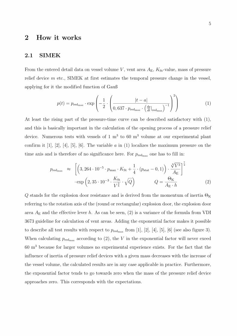
to describe all test results with respect to predmax from [1], [2], [4], [5], [6] (see also figure 3).
When calculating predmax according to (2), the V in the exponential factor will never exeed
60 m3 because for larger volumes no experimental experience exists. For the fact that the
influence of inertia of pressure relief devices with a given mass decreases with the increase of
the vessel volume, the calculated results are in any case applicable in practice. Furthermore,
the exponential factor tends to go towards zero when the mass of the pressure relief device
approaches zero. This corresponds with the expectations.
6 2 HOW IT WORKS
Figure 3: Observed maximum reduced pressure as a function of KSt-value and the resistance
of the explosion door Q. Every point is the middle of three measurements in a 9.4 m3-vessel.
The fitted surface is described by (2) with a correlation coefficient of R2 ≈ 0.9.
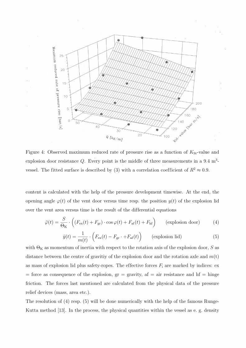
The maximum reduced rate of pressure rise is calculated by:
dp
dt
∣∣∣∣redmax
≈ 1, 72 · KSt3√
V· predmax
pmax
(3)
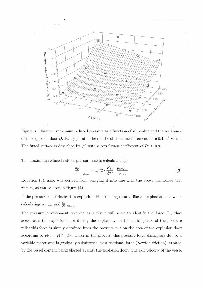
Equation (3), also, was derived from bringing it into line with the above mentioned test
results, as can be seen in figure (4).
If the pressure relief device is a explosion lid, it’s being treated like an explosion door when
calculating predmax and dpdt|redmax
.
The pressure development received as a result will serve to identify the force FEx that
accelerates the explosion door during the explosion. In the initial phase of the pressure
relief this force is simply obtained from the pressure put on the area of the explosion door
according to FEx = p(t) · AE. Later in the process, this pressure force disappears due to a
variable factor and is gradually substituted by a frictional force (Newton friction), created
by the vessel content being blasted against the explosion door. The exit velocity of the vessel
2.1 SIMEK 7
Figure 4: Observed maximum reduced rate of pressure rise as a function of KSt-value and
explosion door resistance Q. Every point is the middle of three measurements in a 9.4 m3-
vessel. The fitted surface is described by (3) with a correlation coefficient of R2 ≈ 0.9.
content is calculated with the help of the pressure development timewise. At the end, the
opening angle ϕ(t) of the vent door versus time resp. the position y(t) of the explosion lid
over the vent area versus time is the result of the differential equations
ϕ(t) =S
ΘK
·((Fex(t) + Fgr) · cos ϕ(t) + Faf(t) + Fhf
)(explosion door) (4)
y(t) =1
m(t)·(Fex(t)− Fgr ·+Faf(t)
)(explosion lid) (5)
with ΘK as momentum of inertia with respect to the rotation axis of the explosion door, S as
distance between the centre of gravitiy of the explosion door and the rotation axle and m(t)
as mass of explosion lid plus safety-ropes. The effective forces Fi are marked by indices: ex
= force as consequence of the explosion, gr = gravity, af = air resistance and hf = hinge
friction. The forces last mentioned are calculated from the physical data of the pressure
relief devices (mass, area etc.).
The resolution of (4) resp. (5) will be done numerically with the help of the famous Runge-
Kutta method [13]. In the process, the physical quantities within the vessel as e. g. density
8 2 HOW IT WORKS
will always be brought in line. The calculated time-dependent opening angle of an explosion
door will give easy access to the needed load FK(t) on hinges or safety-ropes of this explosion
door. From the time-dependent position of an explosion lid over the vent area the load on the
safety-ropes FD(t) of the referring explosion lid can be derived. The corresponding formulas
are:
FK(t) =
√(m · S · ϕ2(t)
)2
+(
ΘS
S· ϕ2(t)
)2
(explosion door) (6)
FD(t) = n · E · AS ·∆l(t)
l(explosion lid) (7)
In (6), m is the mass and ΘS the momentum of inertia of the explosion door. The latter
refers to the rotation axis through the centre of gravity of the explosion door. ϕ and ϕ are
the time-dependent angular velocity and the angular acceleration of the explosion door. In
(7), n is for quantity, E for modulus of elasticity, AS for area of cross-section and l for length
of the safety-ropes. ∆t(t) is the safety rope streching during the catching process.
The results of (4) and (5) create the basis for the calculation in the event that the fastenings of
the pressure relief devices are too weak and cannot hold them in place. With the parameters
of initial velocity, start height and start angle the equation of movement for the oblique
throw with Newton friction
m · ~r(t) = −1
2· ρa · N(t) · r(t) · ~r(t)−m · g · ~ey (8)
can be solved by numerical integration. The result is the trajectory of the catapulted away
pressure relief device. ρa stands for density of air, ~r(t), ~r(t) and ~r(t) stand for time-dependent
vector of location and its derivations, m for the mass of the torn away pressure relief de-
vice, g for gravity and ~ey is the normalized vector in y-direction. The flying pressure relief
device will always be assumed to be a rotating disk. This assumption is taken into consid-
eration in (8) by the variable tensor N(t) and is described in the following. In Newton’s
friction law appears, besides the above mentioned quantities, the bodycharacteristic drag
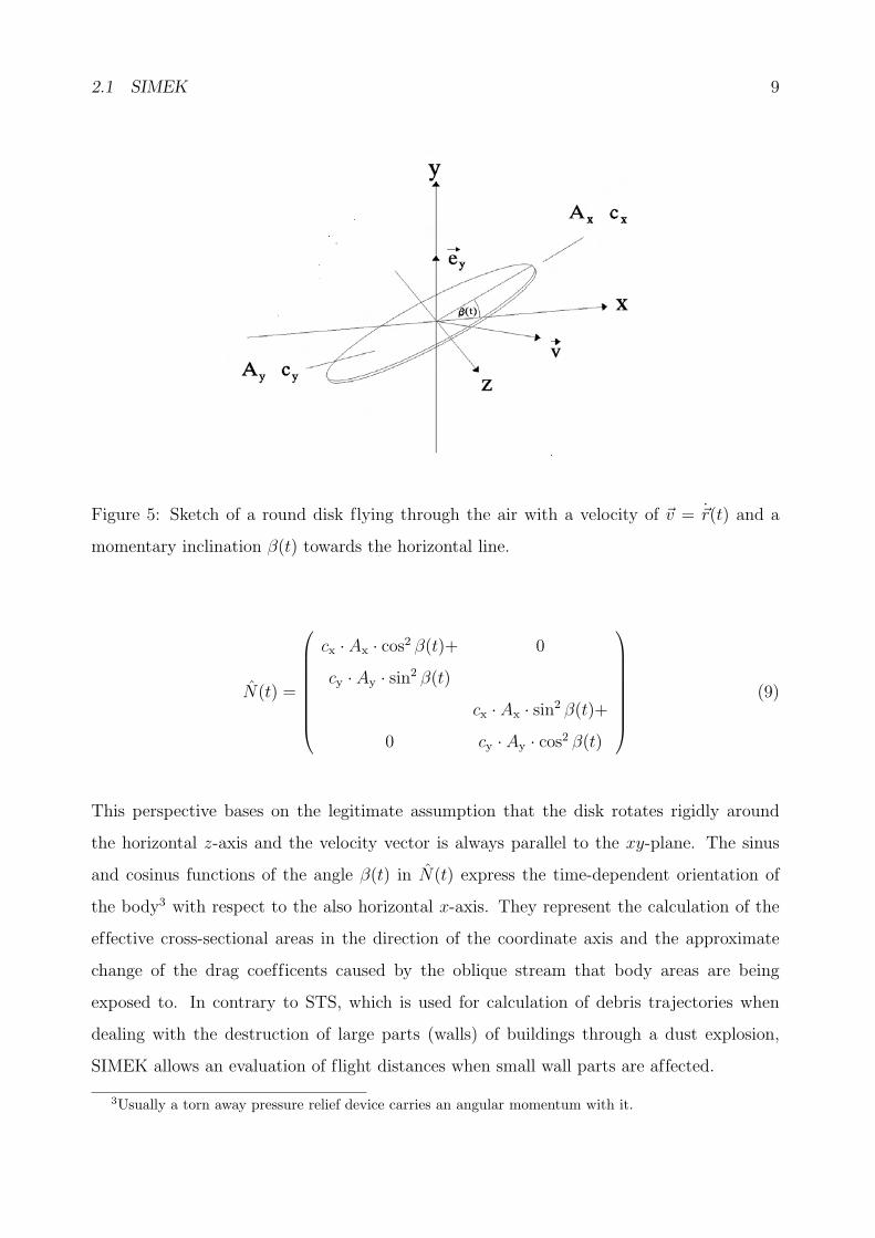
coefficient cw and the body’s cross-sectional area. A round disk flying through the air
has two fundamentally different cross-sectional areas Ax, Ay resp. drag coefficients cx, cy as
can easily be recognized in figure 5. This circumstance can be described quite well by the
tensor (9).
2.1 SIMEK 9
Figure 5: Sketch of a round disk flying through the air with a velocity of ~v = ~r(t) and a
momentary inclination β(t) towards the horizontal line.
N(t) =
cx · Ax · cos2 β(t)+ 0
cy · Ay · sin2 β(t)
cx · Ax · sin2 β(t)+
0 cy · Ay · cos2 β(t)
(9)
This perspective bases on the legitimate assumption that the disk rotates rigidly around
the horizontal z-axis and the velocity vector is always parallel to the xy-plane. The sinus
and cosinus functions of the angle β(t) in N(t) express the time-dependent orientation of
the body3 with respect to the also horizontal x-axis. They represent the calculation of the
effective cross-sectional areas in the direction of the coordinate axis and the approximate
change of the drag coefficents caused by the oblique stream that body areas are being
exposed to. In contrary to STS, which is used for calculation of debris trajectories when
dealing with the destruction of large parts (walls) of buildings through a dust explosion,
SIMEK allows an evaluation of flight distances when small wall parts are affected.
3Usually a torn away pressure relief device carries an angular momentum with it.
10 2 HOW IT WORKS
2.2 STS
STS is for calculation of trajectories of debris catapulted away after a dust explosion in
a building or container. Prerequisite for the application of STS is that large parts of the
container were destroyed. As a result the trajectory of debris with the most probable and
with the largest possible flight range together with the respective kinetic impact energies will
be found. The fundament for the calculation of debris’ trajectories after a dust explosion is
– as in SIMEK – the numerical solving of equation (8). However, when applying STS the
difficulty is to determine the initial conditions like start velocity, start angle, start height
etc. of the debris, which are needed for calculating the trajectory. In the following the
formulas for the determination of the initial conditions are sketched. The derivation of these
formulas is stated more precisely in [10].
The calculation of the initial velocity v0 of the debris is done by using a combination of the
equation of Gurney and of an ideal gas as well as the first main proposition of thermody-
namics:
v0 ≈
√√√√2 · cv · T0 ·(
pb
p0
− 1
)·(
m
((pb − p0) · p−1max · ρs · V
+1
2
)− 12
(10)
Here, pb is the pressure within the building at the point the building bursts, T0 resp. p0
is the norm temperature resp. the norm pressure, cv is the specific heat capacity of air at
constant volume, ρs is the density of the dust/air-mixture, V is the volume filled with the
dust/air-mixture, m is the torn off mass and pmax is the dust explosion characteristic of the
maximum explosion gauge pressure. If predmax > pb, the former will substitute pb in (10). ρs
is assumed to be 2 kgm3 in the program. The rest of the data for a building can be entered
quite easily. Formula (10) is for cylindrical buildings. If the building in question is cuboid,
the fraction 12
within the brackets of (10) has to be substituted by 35.
The start angle α (with respect to the horizontal line) of debris for the trajectory with
maximum range is described by
α = arccos
√
2 · (v40 + 3 · v2
0 · h · g + 2 · h2 · g2)
2 · (v20 + h · g)
(11)
h is the initial height, g is the gravity and v0 is the start velocity of debris. For evaluating
the most probable trajectory of debris, α = 0 rad is assumed.
2.3 VENT 11
The initial height h is derived from the location of the upper edge of the destroyed wall
(maximum range) resp. from the location of the centre of the destroyed wall (most probable
range).
With the known density ρs and the thickness of the wall material cs of the building and with
the area Ay (see figure 5) of a typical fragment, the mass of this fragment is derived from
m = ρw · Ay · cs (12)
For there flight through the air the fragments of debris are being taken as rotating round
disks, just like in SIMEK. The calculation of the trajectories and the kinetic impact energies
will then be done, as described in 2.1, through numerical integration of the equation (8).
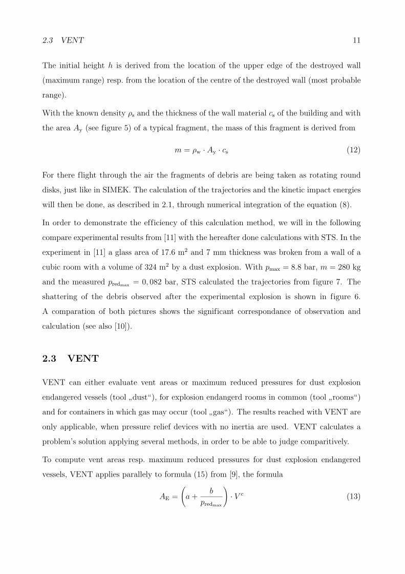
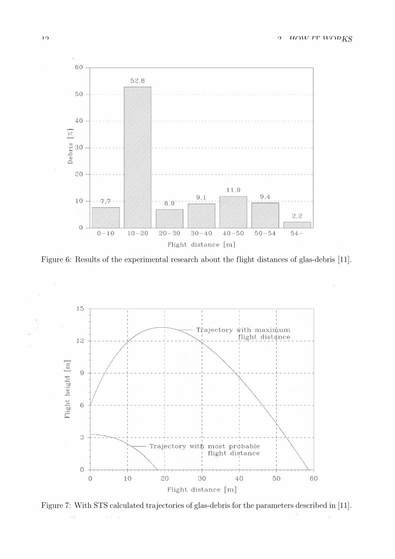
In order to demonstrate the efficiency of this calculation method, we will in the following
compare experimental results from [11] with the hereafter done calculations with STS. In the
experiment in [11] a glass area of 17.6 m2 and 7 mm thickness was broken from a wall of a
cubic room with a volume of 324 m2 by a dust explosion. With pmax = 8.8 bar, m = 280 kg
and the measured predmax = 0, 082 bar, STS calculated the trajectories from figure 7. The
shattering of the debris observed after the experimental explosion is shown in figure 6.
A comparation of both pictures shows the significant correspondance of observation and
calculation (see also [10]).
2.3 VENT
VENT can either evaluate vent areas or maximum reduced pressures for dust explosion
endangered vessels (tool”dust“), for explosion endangerd rooms in common (tool
”rooms“)
and for containers in which gas may occur (tool”gas“). The results reached with VENT are
only applicable, when pressure relief devices with no inertia are used. VENT calculates a
problem’s solution applying several methods, in order to be able to judge comparitively.
To compute vent areas resp. maximum reduced pressures for dust explosion endangered
vessels, VENT applies parallely to formula (15) from [9], the formula
AE =
(a +
b
predmax
)· V c (13)
12 2 HOW IT WORKS
Figure 6: Results of the experimental research about the flight distances of glas-debris [11].
Figure 7: With STS calculated trajectories of glas-debris for the parameters described in [11].
2.4 AD-formula 13
a, b and c are empirically defined coefficients. They depend on the dust hazard class and
also on whether the maximum reduced pressure is above or below 0.5 bar. Based on the
research results of [20], [21], [22] in the calculation of AE with the help of (15) a correction
can be chosen that takes into consideration the way of filling4 of the vessel.
To calculate vent areas AE resp. reduced pressures pred for explosion endangered rooms,
VENT employs the four evaluation methods (14), (15), (16) and (17) simultaneously, so it
is possible to compare these results directly:
AE =7.5 · FO
pred · 100(14)
FO is the surface of the inner walls of the room. Here, the reduced pressure pred is defined
as the pressure of the weakest wall structure will only just withstand. Formula (14) is taken
from [24]. The following two methods of evaluation (15) and (16) can be found in a newer
and an older version of [9]:
AE = (3.264 · 10−5 · pmax ·KSt · p−0.569red + 0.27 · p−0.5
red · (pstat − pred)) · V 0.753 (15)
AE = (3.264 · 10−5 · pmax ·KSt · p−0.569red ) · V 0.753 (16)
The fourth and last calculation method (17) is mentioned in [23]:
AE =C · FO√
pred
(17)
Here C is a constant. Its values are tabulated in [23].
The formula for the calculation of vent areas for gas explosion endangerd containers
AE = (0.1265 · log(KG)− 0.0567) · p−0.5817redmax
· V23 (18)
can be found in publication [25].
2.4 AD-formula
In the AD-formula software only equations are in use, which can be consulted in the pocket-
book or CD-ROM edition of the AD-instructions. For more information the reading of [26]
is recommended.
4Filling of the vessel pneumatical tangential, pneumatical vertical or mechanical.
14 3 HOW TO USE IT
3 How to use it
At present ExProtect is a usually Windows 3.1/3.11 resp. Windows 95/NT application.
It owns a simple routine to install the program easily on every IBM-compatible computer.
After running this little install program under Windows 3.1/3.11, a new group appears in
the Windows main menu, which is titled”FSA“. It contains the FSA logo to start ExProtect
by a double mouse-click on it. The install routine under Windows 95/NT creates the icon
for starting ExProtect in the Windows start menu.
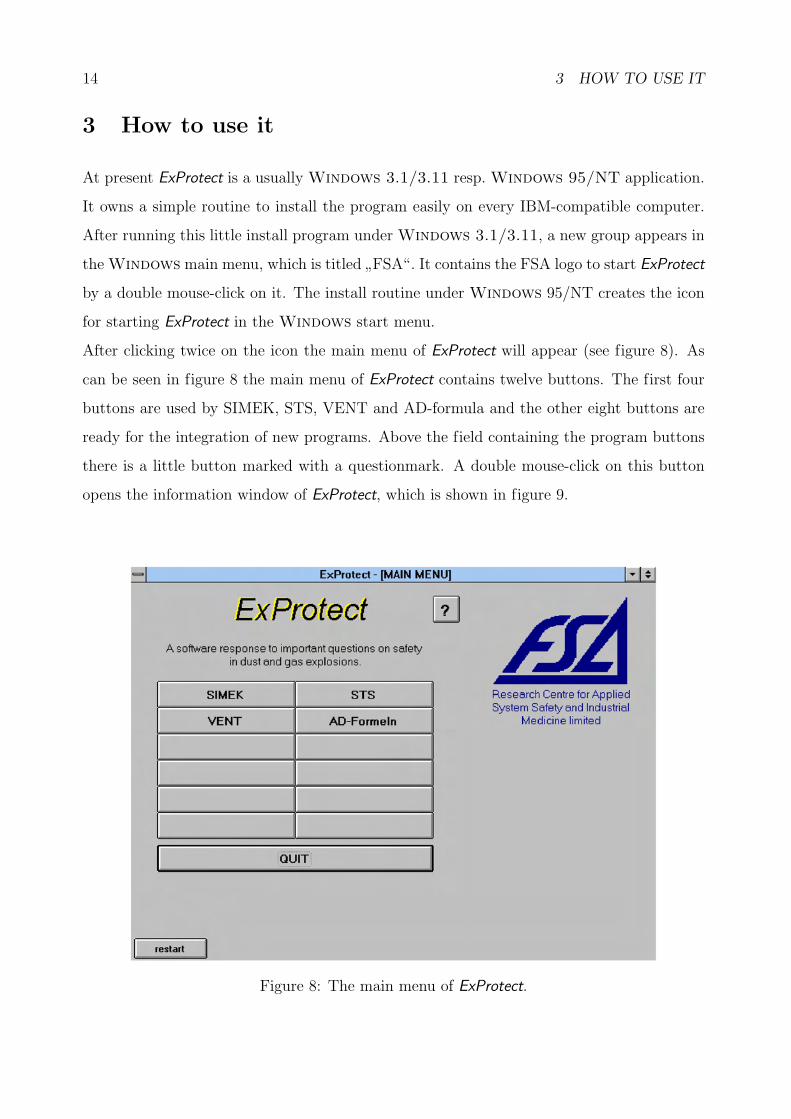
After clicking twice on the icon the main menu of ExProtect will appear (see figure 8). As
can be seen in figure 8 the main menu of ExProtect contains twelve buttons. The first four
buttons are used by SIMEK, STS, VENT and AD-formula and the other eight buttons are
ready for the integration of new programs. Above the field containing the program buttons
there is a little button marked with a questionmark. A double mouse-click on this button
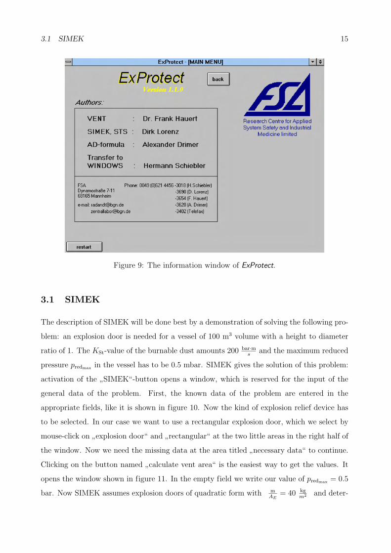
opens the information window of ExProtect, which is shown in figure 9.
Figure 8: The main menu of ExProtect.
3.1 SIMEK 15
Figure 9: The information window of ExProtect.
3.1 SIMEK
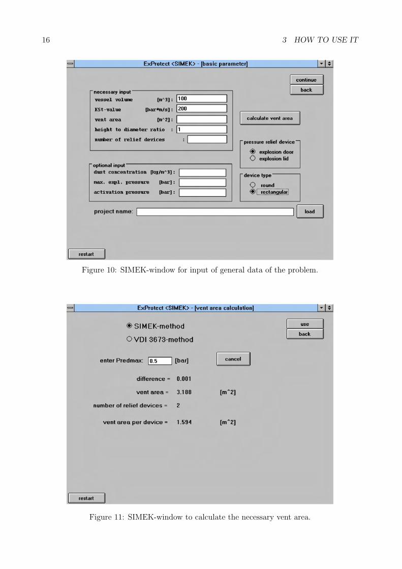
The description of SIMEK will be done best by a demonstration of solving the following pro-
blem: an explosion door is needed for a vessel of 100 m3 volume with a height to diameter
ratio of 1. The KSt-value of the burnable dust amounts 200 bar·ms
and the maximum reduced
pressure predmax in the vessel has to be 0.5 mbar. SIMEK gives the solution of this problem:
activation of the”SIMEK“-button opens a window, which is reserved for the input of the
general data of the problem. First, the known data of the problem are entered in the
appropriate fields, like it is shown in figure 10. Now the kind of explosion relief device has
to be selected. In our case we want to use a rectangular explosion door, which we select by
mouse-click on”explosion door“ and
”rectangular“ at the two little areas in the right half of
the window. Now we need the missing data at the area titled”necessary data“ to continue.
Clicking on the button named”calculate vent area“ is the easiest way to get the values. It
opens the window shown in figure 11. In the empty field we write our value of predmax = 0.5
bar. Now SIMEK assumes explosion doors of quadratic form with mAE
= 40 kgm2 and deter-
16 3 HOW TO USE IT
Figure 10: SIMEK-window for input of general data of the problem.
Figure 11: SIMEK-window to calculate the necessary vent area.
3.1 SIMEK 17
mines size and number of the needed explosion doors by using a trial and error algorithm
in combination with formula (2). If we select”VDI 3673-method“ on top of the window,
we obtain the size of the vent area evaluated with formula (15). This feature is only for
comparison of both evaluated sizes of vent areas. In our case we use”SIMEK-method“ for
the calculation and after the algorithm is finished we click on the button marked”use“ to
return to the window for the data input. We notice, that SIMEK found a solution with two
explosion doors. To continue, the data for”optional input“ are not necessary5. That’s why
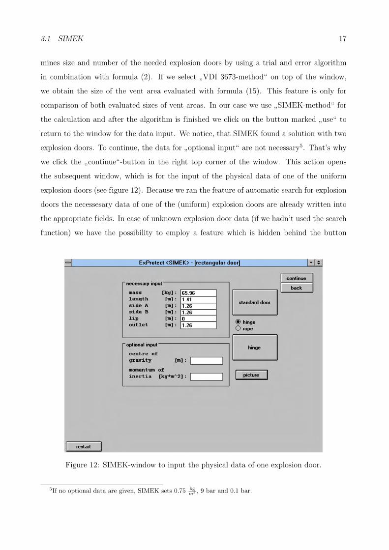
we click the”continue“-button in the right top corner of the window. This action opens
the subsequent window, which is for the input of the physical data of one of the uniform
explosion doors (see figure 12). Because we ran the feature of automatic search for explosion
doors the necessesary data of one of the (uniform) explosion doors are already written into
the appropriate fields. In case of unknown explosion door data (if we hadn’t used the search
function) we have the possibility to employ a feature which is hidden behind the button
Figure 12: SIMEK-window to input the physical data of one explosion door.
5If no optional data are given, SIMEK sets 0.75 kgm3 , 9 bar and 0.1 bar.
18 3 HOW TO USE IT
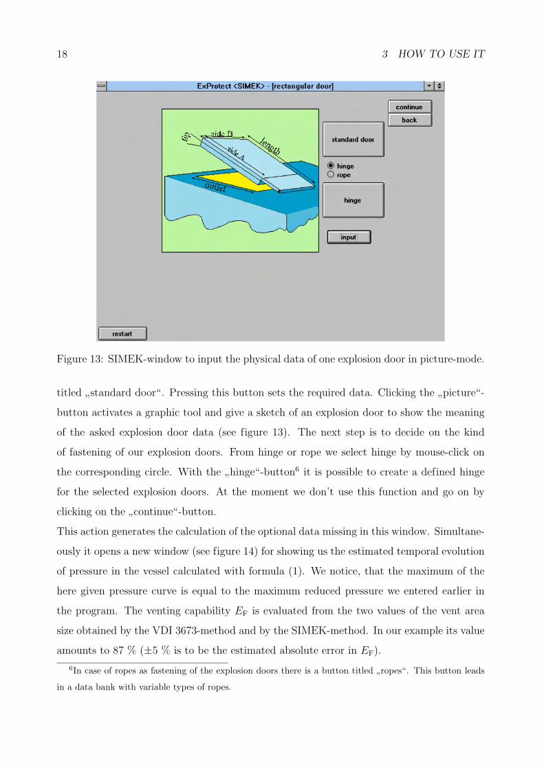
Figure 13: SIMEK-window to input the physical data of one explosion door in picture-mode.
titled”standard door“. Pressing this button sets the required data. Clicking the
”picture“-
button activates a graphic tool and give a sketch of an explosion door to show the meaning
of the asked explosion door data (see figure 13). The next step is to decide on the kind
of fastening of our explosion doors. From hinge or rope we select hinge by mouse-click on
the corresponding circle. With the”hinge“-button6 it is possible to create a defined hinge
for the selected explosion doors. At the moment we don’t use this function and go on by
clicking on the”continue“-button.
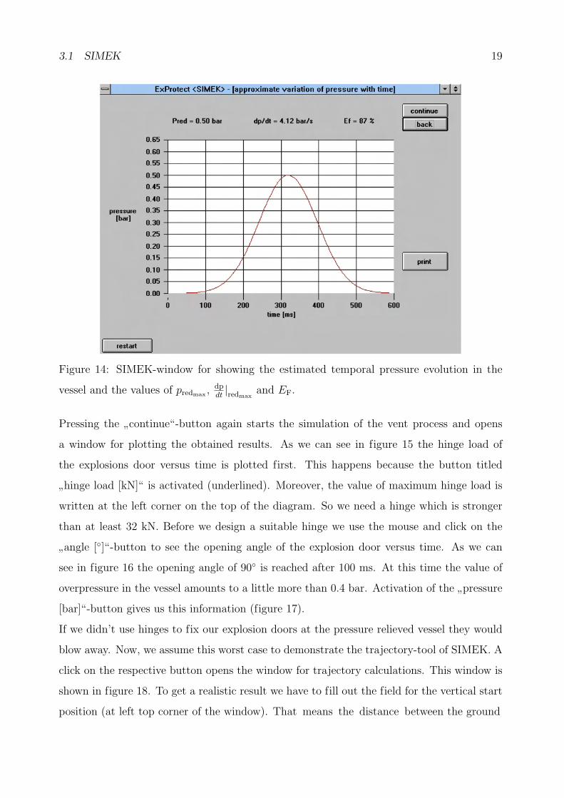
This action generates the calculation of the optional data missing in this window. Simultane-
ously it opens a new window (see figure 14) for showing us the estimated temporal evolution
of pressure in the vessel calculated with formula (1). We notice, that the maximum of the
here given pressure curve is equal to the maximum reduced pressure we entered earlier in
the program. The venting capability EF is evaluated from the two values of the vent area
size obtained by the VDI 3673-method and by the SIMEK-method. In our example its value
amounts to 87 % (±5 % is to be the estimated absolute error in EF).
6In case of ropes as fastening of the explosion doors there is a button titled ”ropes“. This button leads
in a data bank with variable types of ropes.
3.1 SIMEK 19
Figure 14: SIMEK-window for showing the estimated temporal pressure evolution in the
vessel and the values of predmax ,dpdt|redmax
and EF.
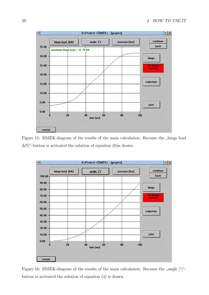
Pressing the”continue“-button again starts the simulation of the vent process and opens
a window for plotting the obtained results. As we can see in figure 15 the hinge load of
the explosions door versus time is plotted first. This happens because the button titled
”hinge load [kN]“ is activated (underlined). Moreover, the value of maximum hinge load is
written at the left corner on the top of the diagram. So we need a hinge which is stronger
than at least 32 kN. Before we design a suitable hinge we use the mouse and click on the
”angle [◦]“-button to see the opening angle of the explosion door versus time. As we can
see in figure 16 the opening angle of 90◦ is reached after 100 ms. At this time the value of
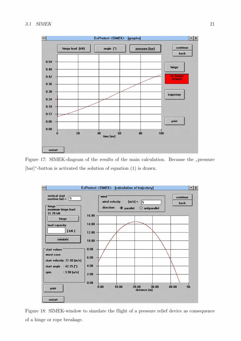
overpressure in the vessel amounts to a little more than 0.4 bar. Activation of the”pressure
[bar]“-button gives us this information (figure 17).
If we didn’t use hinges to fix our explosion doors at the pressure relieved vessel they would
blow away. Now, we assume this worst case to demonstrate the trajectory-tool of SIMEK. A
click on the respective button opens the window for trajectory calculations. This window is
shown in figure 18. To get a realistic result we have to fill out the field for the vertical start
position (at left top corner of the window). That means the distance between the ground
20 3 HOW TO USE IT
Figure 15: SIMEK-diagram of the results of the main calculation. Because the”hinge load
[kN]“-button is activated the solution of equation (6)is drawn.
Figure 16: SIMEK-diagram of the results of the main calculation. Because the”angle [◦]“-
button is activated the solution of equation (4) is drawn.
3.1 SIMEK 21
Figure 17: SIMEK-diagram of the results of the main calculation. Because the”pressure
[bar]“-button is activated the solution of equation (1) is drawn.
Figure 18: SIMEK-window to simulate the flight of a pressure relief device as consequence
of a hinge or rope breakage.
22 3 HOW TO USE IT
and the height that the explosion door is fixed. In our example we assume a vertical start
position of 5 m. Moreover, it is possible to take a wind velocity and a wind direction into
consideration. We select a wind of 5 ms
which blows in flight direction (parallel). We enter
this value of wind velocity in the reserved field and click with the mouse on the circle titled
”parallel“ (both at the centre on top of the window). Pressing the
”simulate“-button starts
the calculation and after a short time the trajectory of our explosion door is plotted. As a
flight distance we obtain about 45 m and the value of maximum height of flight amounts to
about 15 m. At the left bottom corner of the window we can read the start parameters of
our worst case calculation. The trajectory depends on the load capacity of the hinge, which
can be written into the reserved field.
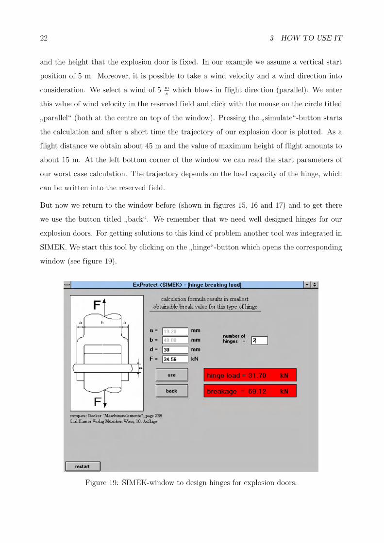
But now we return to the window before (shown in figures 15, 16 and 17) and to get there
we use the button titled”back“. We remember that we need well designed hinges for our
explosion doors. For getting solutions to this kind of problem another tool was integrated in
SIMEK. We start this tool by clicking on the”hinge“-button which opens the corresponding
window (see figure 19).
Figure 19: SIMEK-window to design hinges for explosion doors.
3.1 SIMEK 23
At the left half of this window a sketch of a special type of hinge is shown. The here employed
evaluation method is only valid for this special kind of hinge, but because it is the weakest
typ of hinge the here obtained results are also useful for other hinge types. First we need
to fill out the field where the number of hinges (per explosions door) is asked for. We want
to use two hinges per explosion door and write this value into the field. To calculate the
break load of our two hinges we also need the diameter d of the hinge axle. We write into
the field”d = “ the estimated value of 30 mm and look at the two red fields at the right
half of the window. The upper of these fields shows the maximum load on our two hinges
and the lower field the actual break load of our two hinges (d = 30 mm). We recognize that
the break load is more than double of the maximum load on the hinges. This is a satisfying
result and we accept it by clicking on the”use“-button.
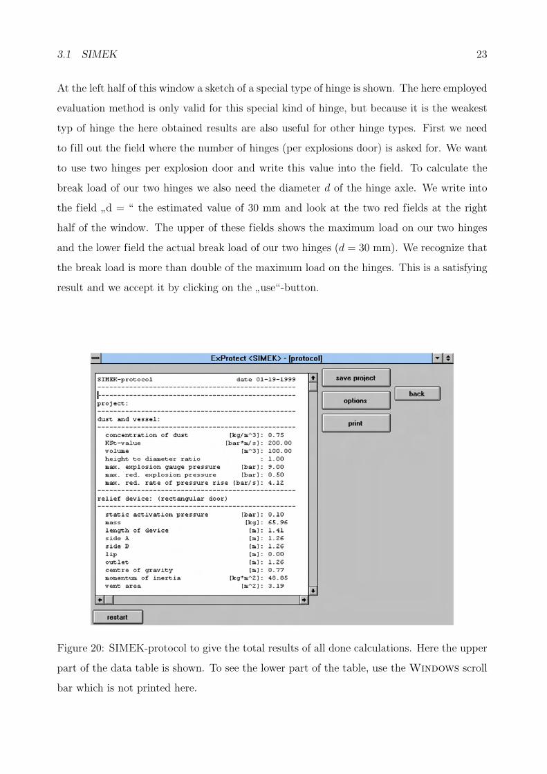
Figure 20: SIMEK-protocol to give the total results of all done calculations. Here the upper
part of the data table is shown. To see the lower part of the table, use the Windows scroll
bar which is not printed here.
24 3 HOW TO USE IT
After returning to the window from which we started the trajectory tool we now open the
last window of SIMEK by pressing the”continue“-button. The SIMEK-protocol window
opens and gives the complete results of all of our calculations in one table (see figure 20).
As we can see, SIMEK offers as one possible solution to our problem resp. example: the
pressure relief has to be done by employing two explosion doors. Mass and area of every
explosion door amounts to 65.96 kg and 1.59 m2. Every explosion door has to be fixed at
the vessel by two hinges assuming that the diameter of the hinge axle amounts to at least
30 mm. With the buttons at the right side of the window it is possible to print the data
table or to save the project. Furthermore the design of the printout can be changed by using
the”options“-button.
As it was demonstrated in our example, SIMEK is a very useful tool to solve different
pressure relief problems in context with explosion doors or lids.
3.2 STS
As mentioned before, STS was written to calculate the flight distances of debris of a
bursting vessel or building as a consequence of a dust explosion inside. To demonstrate the
efficiency of STS the following example is to be contemplated: a cuboid building (height
to diameter ratio is 1) of 1000 m3 volume and is made of masonry of 150 mm thickness
bursts due to a dust explosion inside. We assume that a quadratic area of 100 m2 of the
building wall is catapulted away. The masonry will burst at a pressure equal or higher than
0.1 bar. The explosion characteristics of the burnable dust are to be KSt = 200 bar·ms
and
pmax = 9 bar. What is the maximum flight distance of the debris and at what distance will
the maximum debris mass be found?
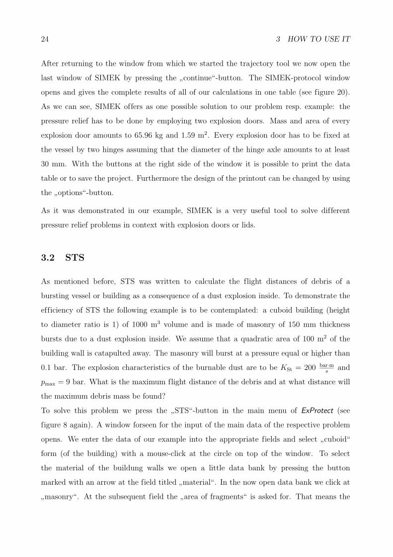
To solve this problem we press the”STS“-button in the main menu of ExProtect (see
figure 8 again). A window forseen for the input of the main data of the respective problem
opens. We enter the data of our example into the appropriate fields and select”cuboid“
form (of the building) with a mouse-click at the circle on top of the window. To select
the material of the buildung walls we open a little data bank by pressing the button
marked with an arrow at the field titled”material“. In the now open data bank we click at
”masonry“. At the subsequent field the
”area of fragments“ is asked for. That means the
3.2 STS 25
Figure 21: STS-window to input the data of the problem dealt with.
largest area of an average fragment. In most cases this parameter is unknown, so STS sets it
on 0.5 m2. This is the most observed value in pertinent experimental determinations. The
asked “centre of area hm“ at the last field is the distance between the centre of the bursting
area and the ground, like it is shown in the sketch at the right half of the window. In our
case this value amounts to 5 m. We click on the”continue“-button at the right top corner of
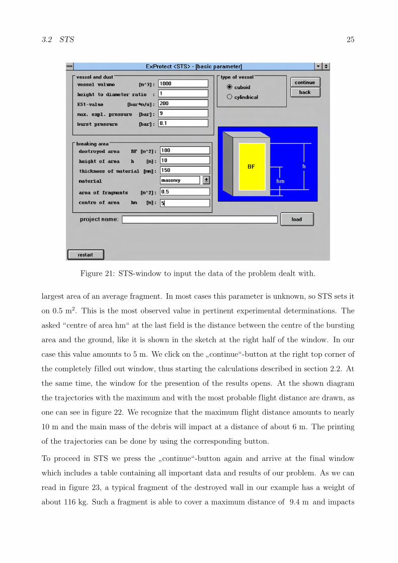
the completely filled out window, thus starting the calculations described in section 2.2. At
the same time, the window for the presention of the results opens. At the shown diagram
the trajectories with the maximum and with the most probable flight distance are drawn, as
one can see in figure 22. We recognize that the maximum flight distance amounts to nearly
10 m and the main mass of the debris will impact at a distance of about 6 m. The printing
of the trajectories can be done by using the corresponding button.
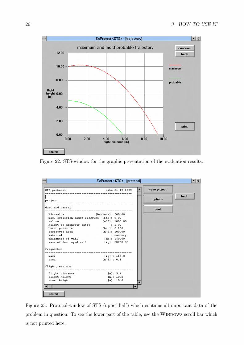
To proceed in STS we press the”continue“-button again and arrive at the final window
which includes a table containing all important data and results of our problem. As we can
read in figure 23, a typical fragment of the destroyed wall in our example has a weight of
about 116 kg. Such a fragment is able to cover a maximum distance of 9.4 m and impacts
26 3 HOW TO USE IT
Figure 22: STS-window for the graphic presentation of the evaluation results.
Figure 23: Protocol-window of STS (upper half) which contains all important data of the
problem in question. To see the lower part of the table, use the Windows scroll bar which
is not printed here.
3.3 VENT 27
with an energie of 13 kJ. The main mass of the debris will be found at a distance of about
5.7 m from the bursted wall. These fragments with the most probable trajectory will have an
impact energie of about 7.5 kJ. As explained before when talking about the protocol-window
of SIMEK, saving and printing of the data is possible by using the relevant buttons. Again,
the”option“-button is forseen for designing the printout of the data table.
As was shown in our example, the radius of the dangerzone referring to flying debris as a
consequence of a dust explosion inside a silo, vessel, container or buidling can be given easily
by employing the program STS of ExProtect.
3.3 VENT
At present only a German version of VENT exists and in addition it is complicated to get
printouts of the VENT windows, thus we refrain from showing the windows of VENT in
several figures. Instead of presenting pictures the functions of the program will be described
verbally only.
As mentioned in section 2.3, VENT is able to solve different kinds of pressure relief prob-
lems by using pressure relief devices without any mass inertia. To demonstrate the tools of
VENT we look back at our example we used in the SIMEK chapter. A vessel of 100 m3
volume with a design strength of 0.5 bar is to be protected against damage from a dust
explosion inside. In the main menu of ExProtect (figure 8) we click on the button ti-
tled”VENT“ to calculate the required vent area. This action opens the main menu of
VENT. In the upper half of this menu an information window can be seen and in the
lower half a window to select of the four tools”dust“,
”rooms“,
”gas“ and
”end“ exists.
To find a solution to our problem we select the tool”dust“ (per mouse-click). Now a
window opens for the data input of the problem. First we have to choose from the calcu-
lation of the vent area AE and the calculation of the maximum reduced pressure predmax .
We select the first. In the subsequent fields we write the data of KSt = 200 bar·ms
,
pmax = 9 bar, pstat = 0.1 bar, V = 100 m3, height to diameter ratio is 1 and the length
and the diameter of a vent duct are zero (no vent duct). In addition to that we can choose
between four kinds of filling the vessel. To demonstrate this we select”mechanical“ which
means that the product (dust) is filled into the vessel from its top and falls freely into it (for
28 3 HOW TO USE IT
example by employing an elevator). Starting the calculation by pressing the”O. K.“-button
gives us the data of table 1 as a result. We notice, that the vent area for a mechanically filled
vessel is less than half of the vent area which is required for a vessel containing a homogen
dust/air-mixture. By using VENT’s graphic tool a corresponding diagram can be created in
which the maximum reduced pressure is viewed as a function of the vent area. Moreover it
is possible to compare the results of two calculations as is shown in figure 24. The second
curve is obtained by using a height to diameter ratio of 3. Data table and diagram can be
printed easily and it is also possible to export the entered and computed values into a file.
dust/air-mixture homogen inhomogen with formula (13) mechanical filling
vent area [m2] 2.79 0.80 2.79 1.12
recoil force [kN] 166.3 47.8 166.1 –
Table 1: Calculated vent areas for a dust explosion endagered and pressure relieved vessel.
Figure 24: Maximum reduced pressure versus vent area calculated with VENT for two
different height to diameter ratios of the vessel. Evaluations done with (16).
3.4 AD-formula 29
In the same way it is described above the two other tools”rooms“ and
”gas“, employing the
formulas (14) to (18), are to be used. We leave VENT by clicking with the mouse on”end“
and return to the main menu of ExProtect.
As a conclusion it can be said that VENT is a software which makes the engagement of the
standard calculation methods referring to pressure relief problems easier.
3.4 AD-formula
The actual version of AD-formula bases on a primitiv BASIC interpreter-code. Therefore it
is of no use to show pictures of the program windows. Like VENT, AD-formula deals with
menus to select the methods of calculation.
Entering AD-formula is done by pressing the corresponding button in the main menu of
ExProtect (see figure 8 again). Here it is only possible to continue or to return. Going on
in AD-formula opens the menu for designing four different structural members for vessels
standing under pressure. These calculations are named B1 to B4 in the AD-instructions
[26]. Additional to the existing possibility to return to the main menu a second menu can be
opened with four more designing tools printed in B5 and B7 to B9 in the AD-instructions
[26]. Every time such a designing tool is started one has to enter some data about the vessel
in question. If the data input is finished the solution of the problem will be given by pressing
the”enter“ key of the computer keyboard. In general, AD-formula is controlled by entering
numbers with the help of the keyboard. In the same way AD-formula can be left to return
to the main menu of ExProtect.
The present version of AD-formula is userunfriendly and will therefore be improved in the
near future. If this is done, AD-formula will be a useful help for the designing of vessels
standing under pressure.
30 REFERENCES
References
[1] M. Seithel: Deckelabsprengung am liegenden und stehenden 1 m3-Behalter mit un-
terschiedlichen Deckelmassen, Berufsgenossenschaft Nahrungsmittel und Gaststatten
(1993)
[2] D. Lorenz, H. Ott, M. Seithel: Untersuchung zur Mechanik von Druckentlast-
ungsklappen und -deckeln beim Entlastungsvorgang, Bericht Nr. F-05-9304/05
der Forschungsgesellschaft fur angewandte Systemsicherheit und Arbeitsmedizin
e. V. (1996)
[3] F. Kossebau: 9 m3-Behalter: Erforderliche Zundverzogerungszeiten fur ungetrocknete
Maisstarke zur Anpassung an die Gleichung zur Berechnung von Druckentlastungs-
f lachen in der Richtlinie VDI 3673, Forschungsgesellschaft fur angewandte System-
sicherheit und Arbeitsmedizin e. V. (1993)
[4] F. Kossebau: Funktionsprufung einer Explosionsentlastungsklappe, Typenbezeich-
nung RLE-S 0.5, Forschungsgesellschaft fur angewandte Systemsicherheit und Arbeits-
medizin e. V. (1994)
[5] F. Kossebau: Funktionsprufung einer Explosionsentlastungsklappe, Typenbezeich-
nung RLE-S 1.0, Forschungsgesellschaft fur angewandte Systemsicherheit und Arbeits-
medizin e. V. (1993)
[6] F. Kossebau: Funktionsprufung einer Explosionsentlastungsklappe, Typenbezeich-
nung RLE-S 1.5, Forschungsgesellschaft fur angewandte Systemsicherheit und Arbeits-
medizin e. V. (1993)
[7] R. Siwek, O. Skov: Modellberechnung zur Dimensionierung von Explosionsklappen
auf der Basis von praxisnahen Explosionsversuchen, VDI Berichte, 701, 569-616, VDI
Verlag (1988)
[8] A. Harmanny: Einf lua der Massentragheitskrafte auf die Entlastungsfahigkeit von
Explosionsklappen, VDI Berichte, 975, 273-284, VDI Verlag (1992)
[9] VDI 3673: Druckentlastung von Staubexplosionen, VDI Verlag (1992)
REFERENCES 31
[10] D. Lorenz, S. Radandt: Trummerf lug in der Umgebung von Staubexplosionsherden
– Vergleich zwischen Modellrechnung und Explosionsereignissen, VDI Berichte, 1272,
347-364, VDI Verlag (1996)
[11] K. Hoppner: Measurment of pressure blast ef fects and f ireball sizes from vented
dust explosions in rooms, CREDIT-Project of the European Commission Final Report,
293-354 (1995)
[12] G. E. Jones, J. E. Kennedy, L. D. Bertholf: Ballistics calculations of R. W.
Gurney, Am. J. Phys., 48, 264-269 (1980).
[13] R. Zurmuhl: Praktische Mathematik fur Ingenieure und Physiker, Springer Verlag,
5. Auflage (1965).
[14] C. Gerthsen, H. O. Kneser, H. Vogel: Physik, Springer Verlag, 14. Auflage
(1982)
[15] W. Greiner: Mechanik, Teil 1, Verlag Harry Deutsch, 6. Auflage (1993)
[16] W. Greiner: Mechanik, Teil 2, Verlag Harry Deutsch, 6. Auflage (1989)
[17] K. H. Decker: Maschinenelemente, Carl Hanser Verlag, 10. Auflage (1990)
[18] DIN-Taschenbuch 59: Drahtseile, Beuth Verlag, 5. Auflage (1990)
[19] K. Feyrer: Drahtseile, Springer Verlag (1994)
[20] F. Hauert, A. Vogl: Measurements of dust cloud characteristics in industrial plants,
Proceedings of the Dust Explosion Conference, London, CREDIT-Project of the Euro-
pean Commission (1995)
[21] F. Hauert, A. Vogl, S. Radandt: Measurement of turbulence and dust concen-
tration in silos and vessels, Prceedings of the 6th International Colloqium on Dust
Explosions, Shenyang, China, 71-80, X. Deng and P. Wolanski editors (1994)
[22] F. Hauert, A. Vogl, S. Radandt: Dust cloud characterization and its inf luence
on the pressure-time-history in silos, Process Safety Progress, 15, No. 3, 178-184 (1996)
32 REFERENCES
[23] NFPA 68: Venting of def lagrations (1988)
[24] G F. Kinney, K. J. Graham: Explosive shocks in air, Springer Verlag (1985)
[25] W. Bartknecht: Explosionsschutz, Springer Verlag (1993)
[26] TUV: AD-Merkblatter, Carl Heymanns und Beuth Verlag (1995)
[27] M. Roser: Investigation of dust explosion phenomena in interconnected process ves-
sels, Doctoral Thesis, Loughborough University, Great Britan (1998)