Embed Size (px)
Citation preview
Extending battery life in smart locks
Chris GlaserMember Group Technical Staff, Applications EngineerLow Power DC/DCTexas Instruments
Aramis P. AlvarezApplications EngineerBuilding AutomationTexas Instruments
Extending battery life in smart locks 2 November 2016
New smart lock power architectures greatly increase battery life by reducing system standby power consumption.
Power management is a key design challenge in every Internet of Things (IoT) and
connected home product. If the consumer experiences product downtime due to dead
batteries or gets tired of changing the batteries too frequently, they will likely choose to
not use the product. This is especially true for smart locks. When a lock malfunctions,
the result is frustration from being locked out of the office or hotel room.
In addition to the relatively high peak current demands of the radio, common in all
IoT applications, smart locks have an additional high peak current demand from the
motor which turns the lock itself. Also, smart locks sit idle for the vast majority of
every day—the time when they are actively locking or unlocking the door is very small.
This combination of high peak current demands and very lengthy, low-power system
standby time demands new power architectures to extend the battery life.
System overview
While smart lock systems may contain many
integrated circuits (ICs) such as light-emitting diode
(LED) drivers, Wi-Fi® communications, and so on,
this paper focuses specifically on these three ICs:
1) microcontroller with wireless connectivity, such
as Bluetooth® low energy;
2) a motor driver; and
3) power management.
Throughout this paper, the term “events” refers to
the door locking or unlocking when the motor is
active. For example, locking the front door and then
unlocking the front door counts as two separate
events. Twenty-four events per day is commonly
used for comparing the performance of different
smart locks.
Wireless microcontroller
In a smart lock product, the wireless microcontroller
(MCU) device communicates with the phone to
lock and unlock the door wirelessly. In order to
do this without any noticeable lag, the wireless
microcontroller needs to be powered on to send an
advertising event signal periodically, and then be put
back into its standby state. Current consumption is
much lower in standby—usually around the single-
digit micro-amp (µA) range. Such a low current
enables long battery life.
Advertising events (not to be confused with the
locking/unlocking events) occur when the wireless
microcontroller periodically wakes up to briefly
transmit identifying information and listen for
incoming connection requests from peer devices
(e.g., a smart phone). The period of advertising
events is programmable on most Bluetooth low
energy devices from 20 ms to 10.24 seconds.
Extending battery life in smart locks 3 November 2016
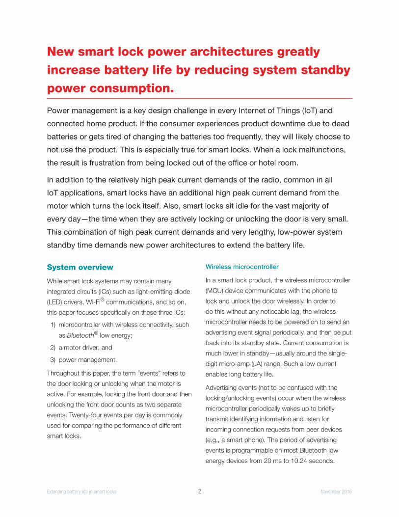
The longer the period, the longer it takes for a
connection but the lower the power consumption.
A period of 500 ms between advertising events
is a good balance between power consumption
and connection speed. Figure 1 shows the
current consumption waveform of a typical
wireless microcontroller with Bluetooth low energy
communication [1]. Default values for the CC2640
current consumptions are shown in Figure 1. The
pie graphs and plots in Figure 6 and Figure 7 (see
page 6) use the worst-case scenario of 9.1 mA of
active current and 2.5 µA of standby current. These
values are used for maximum output power.
Since the advertising event period is programmable,
the two most important values to look for when
choosing a Bluetooth low energy radio, in terms
of power consumption, are active (during an
advertising event) and standby currents. The supply
voltage range of the SimpleLink™ Bluetooth low
energy CC2640 wireless MCU is 1.8 V to 3.8 V. In
this application note 2.5 V will be used to allow easy
comparison between the different configurations.
Motor
All smart lock products need a motor and motor
driver in order to turn the lock in either direction
(lock and unlock) wirelessly and without a physical
key. The current profile of the motor is different
for each type of door lock, because the amount
of torque needed to turn the lock differs between
different brands of door locks. On many locks, the
current through the motor ramps up and peaks at
around one amp. There are a number of sources of
power dissipation in a motor driver, but the biggest
source is the on-resistance of its MOSFETs. When
choosing a motor driver, the highest efficiency is
achieved with a very low on-resistance. The motor
driver, such as a DRV8833, must work with the
smart lock’s power source and the specific motor
used. Considering both of these, the motor driver
voltage is typically around 5 V.
Power management
Power management is required to convert the
varying battery voltage to the voltages required
by each of the loads: wireless microcontroller,
motor driver and any other sub-systems. Power
management adds cost, size and inefficiency to the
system. Thus, it is important to design the entire
system with the power management in mind—the
power management must work together with
each sub-system.
The power management’s efficiency is critical to the
performance of the overall system, especially in an
Figure 1. Current consumption versus time during a Bluetooth low energy advertising event.
Figure 1
6.1mA
1.2μA
Advertising Advertising Advertising Advertising AdvertisingEvent Event Event Event Event
Extending battery life in smart locks 4 November 2016
IoT application such as a smart lock. This efficiency
is important at the full system load with motor
turning and wireless microcontroller connecting,
but critical when the system is in standby-mode—
drawing micro amps (µA) of current. Being efficient
at both light and heavy loads is challenging and
requires specially-designed ICs.
The power management must ultimately run off of
the user-installed batteries. The choice of battery
type, number and configuration goes hand-in-hand
with the system’s power architecture and power
management selection. AA-size alkaline batteries
are widely used in smart locks due to their wide
availability to consumers and low cost. The average
per-cell voltage of an AA cell is around 1.25 V,
though their voltage varies from under 1 V when fully
discharged to 1.6 V when brand new. With four AA
cells, over four years of battery life is achieved [2].
Whereas many existing smart locks focus on
achieving lowest-cost power management with
low drop-out (LDO) linear regulators—at the
expense of efficiency—newer, cost-effective power
management more than doubles the battery life with
minimal added cost. Switching DC/DC converters,
both boost (sometimes called a step-up) and buck
(sometimes called a step-down) converters, offer
higher efficiency and a corresponding longer battery
life compared to LDO implementations.
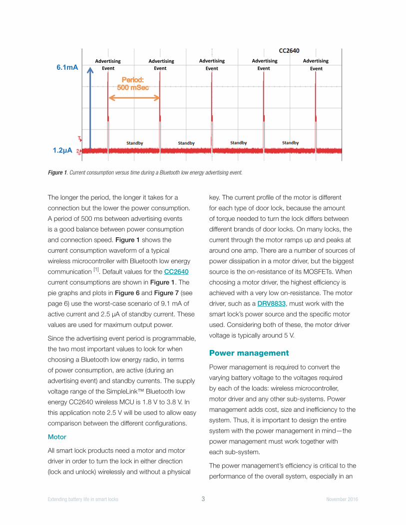
Linear regulator
The four AA batteries are connected as 4s1p (four
series cells and one parallel cell) to create a 5-V
supply voltage to power the motor. Now, only a
simple motor driver is needed to turn the motor
on or off without any added power management.
Because of this, the motor sub-system operates at
nearly 100 percent efficiency.
LDOs step down the higher battery voltage to lower
voltages. An LDO is used to convert the 5-V battery
to the 2.5 V required by the wireless microcontroller.
Any LDO converting 5 V to 2.5 V is 50 percent
efficient at best, with much lower efficiency obtained
in standby-mode due to the LDO’s quiescent
current (sometimes called ground current) [3]. For
example, the TPS76625 is suitable to convert
four AA batteries to 2.5 V. This device achieves
50 percent efficiency at higher loads, but only two
percent efficiency at the 1.2 µA standby load due to
its 35-µA quiescent current. The very low efficiency
results in relatively high power consumption when
the smart lock is in standby—this reduces battery
life. Figure 2 shows a typical block diagram of an
LDO-based system.
Boost converter
To overcome the LDO’s low efficiency in standby-
mode, the battery configuration is rearranged and
a boost converter is used instead. In this power
architecture, the wireless MCU connects directly to
the battery pack, which is arranged as a 2s2p (two
series and two parallel cells). Since four cells are
still used, the cost and energy are the same as the
previous case. But since there are only two cells in
series, the total battery pack voltage is just 2.5 V—a
perfect match for the wireless MCU. Now, this
connection is 100 percent efficient.
However, the motor still requires 5 V to operate.
From the 2.5-V battery, a boost converter must
Figure 2. Smart lock block diagram using an LDO and four AA cells connected in series.
4s1p
Power
Management
LDO
Motor Driver
with Motor
Wireless
Microcontroller
2.5 V5 V
LDO full-load efficiency
ηLDO1 = 50%
LDO standby efficiency
ηLDO2 = 2%
Motor driver efficiency
ηMD = 100%
AA
AA
AA
AA
Extending battery life in smart locks 5 November 2016
be used. A typical boost converter, such as the
TPS61030, has around 85 percent efficiency when
boosting to drive a motor. Due to the efficiency and
boost ratio (where the output voltage is greater than
the input voltage), the boost converter draws very
high currents from the battery which increases the
losses. Figure 3 shows a typical block diagram of a
boost-based system.
Buck converter
Taking the same power architecture as the LDO
system, a buck converter is used in place of the
LDO to dramatically increase the efficiency. At
the wireless microcontroller’s full load, the buck
converter, such as a TPS62745, is 90 percent
efficient. The motor sub-system remains at nearly
100 percent efficiency because it is connected
directly to the battery pack. Figure 4 shows a
typical block diagram of a buck-based system.
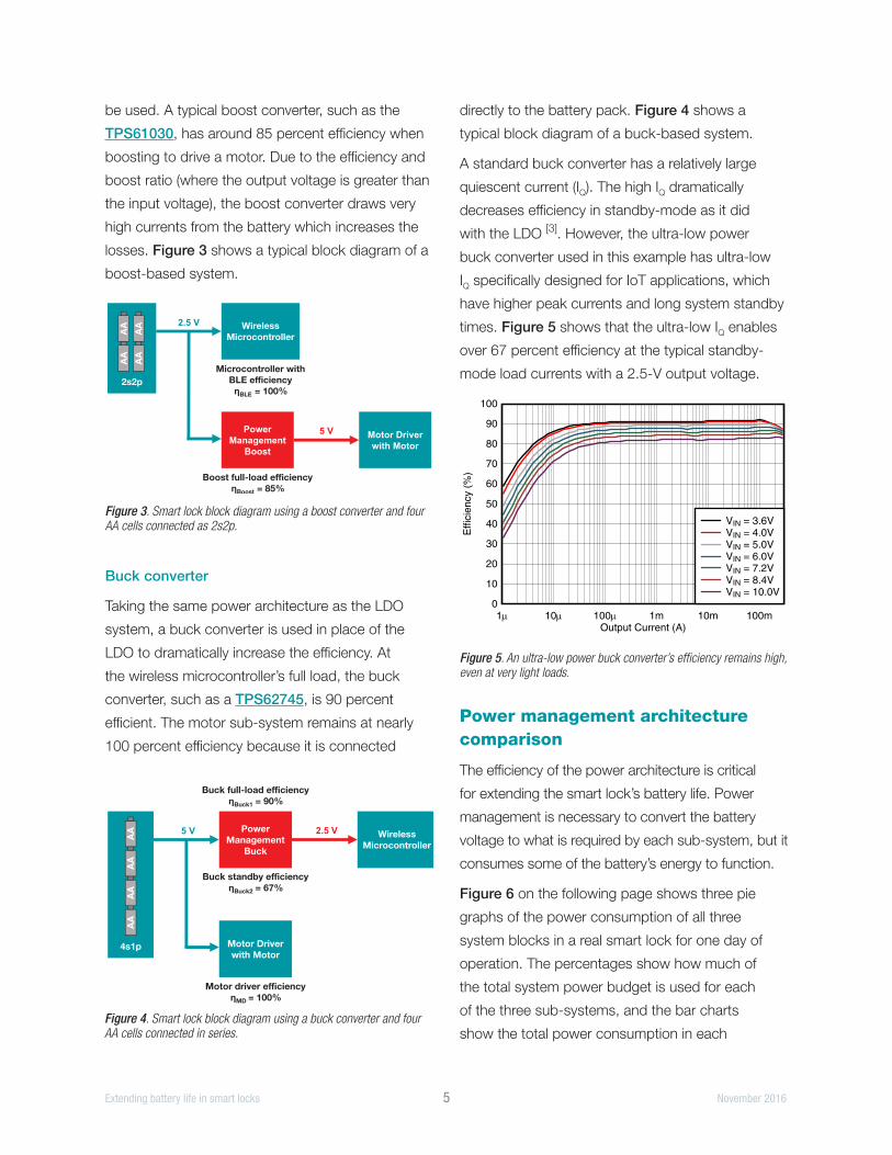
A standard buck converter has a relatively large
quiescent current (IQ). The high IQ dramatically
decreases efficiency in standby-mode as it did
with the LDO [3]. However, the ultra-low power
buck converter used in this example has ultra-low
IQ specifically designed for IoT applications, which
have higher peak currents and long system standby
times. Figure 5 shows that the ultra-low IQ enables
over 67 percent efficiency at the typical standby-
mode load currents with a 2.5-V output voltage.
Power management architecture comparison
The efficiency of the power architecture is critical
for extending the smart lock’s battery life. Power
management is necessary to convert the battery
voltage to what is required by each sub-system, but it
consumes some of the battery’s energy to function.
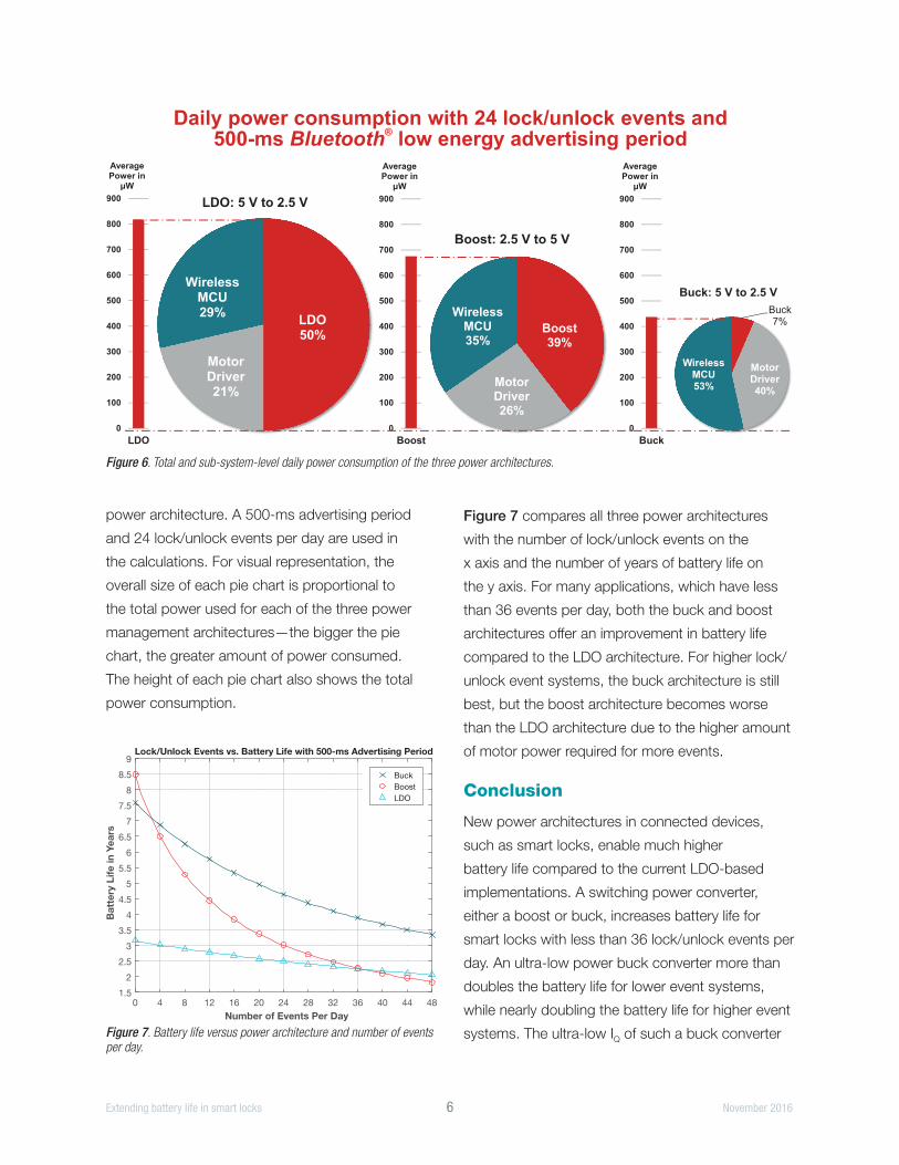
Figure 6 on the following page shows three pie
graphs of the power consumption of all three
system blocks in a real smart lock for one day of
operation. The percentages show how much of
the total system power budget is used for each
of the three sub-systems, and the bar charts
show the total power consumption in each
Power
Management
Boost
Motor Driver
with Motor
5 V
2.5 V
Boost full-load efficiency
ηBoost = 85%
Microcontroller with
BLE efficiency
ηBLE = 100%2s2p
Wireless
Microcontroller
AA
AA
AA
AA
Figure 3. Smart lock block diagram using a boost converter and four AA cells connected as 2s2p.
Power
Management
Buck
Motor Driver
with Motor
2.5 V5 V
Motor driver efficiency
ηMD = 100%
Buck standby efficiency
ηBuck2 = 67%
Buck full-load efficiency
ηBuck1 = 90%
4s1p
AA
AA
AA
AA Wireless
Microcontroller
Figure 4. Smart lock block diagram using a buck converter and four AA cells connected in series.
Output Current (A)
Out
put V
olta
ge (
V)
3.201
3.234
3.267
3.300
3.333
3.366
3.399
1 10 100 1m 10m 100m
D005
VIN = 4.0VVIN = 5.0VVIN = 6.0VVIN = 7.2VVIN = 8.4VVIN = 10.0V
Output Current (A)
Out
put V
olta
ge (
V)
2.425
2.450
2.475
2.500
2.525
2.550
2.575
2.600
2.625
1 10 100 1m 10m 100m
D006
VIN = 3.6VVIN = 4.0VVIN = 5.0VVIN = 6.0VVIN = 7.2VVIN = 8.4VVIN = 10.0V
Output Current (A)
Effi
cien
cy (
%)
0
10
20
30
40
50
60
70
80
90
100
1 10 100 1m 10m 100m
D003
VIN = 3.6VVIN = 4.0VVIN = 5.0VVIN = 6.0VVIN = 7.2VVIN = 8.4VVIN = 10.0V
Output Current (A)
Effi
cien
cy (
%)
0
10
20
30
40
50
60
70
80
90
100
1 10 100 1m 10m 100m
D004
VIN = 3.6VVIN = 4.0VVIN = 5.0VVIN = 6.0VVIN = 7.2VVIN = 8.4VVIN = 10.0V
Output Current (A)
Effi
cien
cy (
%)
0
10
20
30
40
50
60
70
80
90
100
1 10 100 1m 10m 100m
D001
VIN = 4.0VVIN = 5.0VVIN = 6.0VVIN = 7.2VVIN = 8.4VVIN = 10.0V
Output Current (A)
Effi
cien
cy (
%)
0
10
20
30
40
50
60
70
80
90
100
1 10 100 1m 10m 100m
D002
VIN = 3.6VVIN = 4.0VVIN = 5.0VVIN = 6.0VVIN = 7.2VVIN = 8.4VVIN = 10.0V
TPS62745, TPS627451SLVSC68A –JUNE 2015–REVISED JUNE 2015 www.ti.com
9.2.3 Application Curves
Figure 6. VOUT = 3.3 V Figure 7. VOUT = 2.5 V
Figure 8. VOUT = 1.8 V Figure 9. VOUT = 1.5 V
Figure 10. VOUT = 3.3 V Figure 11. VOUT = 2.5 V
16 Submit Documentation Feedback Copyright © 2015, Texas Instruments Incorporated
Product Folder Links: TPS62745 TPS627451
Figure 5. An ultra-low power buck converter’s efficiency remains high, even at very light loads.
Extending battery life in smart locks 6 November 2016
power architecture. A 500-ms advertising period
and 24 lock/unlock events per day are used in
the calculations. For visual representation, the
overall size of each pie chart is proportional to
the total power used for each of the three power
management architectures—the bigger the pie
chart, the greater amount of power consumed.
The height of each pie chart also shows the total
power consumption.
Figure 7 compares all three power architectures
with the number of lock/unlock events on the
x axis and the number of years of battery life on
the y axis. For many applications, which have less
than 36 events per day, both the buck and boost
architectures offer an improvement in battery life
compared to the LDO architecture. For higher lock/
unlock event systems, the buck architecture is still
best, but the boost architecture becomes worse
than the LDO architecture due to the higher amount
of motor power required for more events.
Conclusion
New power architectures in connected devices,
such as smart locks, enable much higher
battery life compared to the current LDO-based
implementations. A switching power converter,
either a boost or buck, increases battery life for
smart locks with less than 36 lock/unlock events per
day. An ultra-low power buck converter more than
doubles the battery life for lower event systems,
while nearly doubling the battery life for higher event
systems. The ultra-low IQ of such a buck converter
Figure 6. Total and sub-system-level daily power consumption of the three power architectures.
Daily power consumption with 24 lock/unlock events and500-ms low energy advertising periodBluetooth
®
Buck
7%
MotorDriver40%
WirelessMCU53%
Buck: 5 V to 2.5 V
LDO50%
MotorDriver21%
WirelessMCU29%
LDO: 5 V to 2.5 V
Boost39%
MotorDriver26%
WirelessMCU35%
Boost: 2.5 V to 5 V
0
100
200
300
400
500
600
700
800
900
LDO
AveragePower in
μW
0
100
200
300
400
500
600
700
800
900
Boost
AveragePower in
μW
0
100
200
300
400
500
600
700
800
900
Buck
AveragePower in
μW
Number of Events Per Day
0 4 8 12 16 20 24 28 32 36 40 44 48
Ba
tte
ry L
ife
in
Ye
ars
1.5
2
2.5
3
3.5
4
4.5
5
5.5
6
6.5
7
7.5
8
8.5
9Lock/Unlock Events vs. Battery Life with 500-ms Advertising Period
Buck
Boost
LDO
Figure 7. Battery life versus power architecture and number of events per day.
is critical to the battery life extension by vastly
increasing the efficiency during the lengthy
standby-modes of such systems. Designers of
connected and IoT products should take another
look at their power management architectures
to make sure their products achieve optimal
battery life.
References
1. Joakim Lindh, Christin Lee, and Marie
Hernes. Measuring Bluetooth Low Energy
Consumption, Texas Instruments Application
Report (SWRA478), December 2016
2. Smart Lock Reference Design Enabling 5+
Years Battery Life on 4× AA Batteries, TI
Design (TIDA-00757)
3. Chris Glaser. IQ: What it is, what it isn’t, and
how to use it, TI Application Note (SLYT412),
2Q11
4. Product folders: CC2640, DRV8833,
TPS76625, TPS61030, TPS62745
SLYY107© 2016 Texas Instruments Incorporated
Important Notice: The products and services of Texas Instruments Incorporated and its subsidiaries described herein are sold subject to TI’s standard terms and conditions of sale. Customers are advised to obtain the most current and complete information about TI products and services before placing orders. TI assumes no liability for applications assistance, customer’s applications or product designs, software performance, or infringement of patents. The publication of information regarding any other company’s products or services does not constitute TI’s approval, warranty or endorsement thereof.
The platform bar and SimpleLink are trademarks of Texas Instruments. All other trademarks are the property of their respective owners.
IMPORTANT NOTICE
Texas Instruments Incorporated and its subsidiaries (TI) reserve the right to make corrections, enhancements, improvements and otherchanges to its semiconductor products and services per JESD46, latest issue, and to discontinue any product or service per JESD48, latestissue. Buyers should obtain the latest relevant information before placing orders and should verify that such information is current andcomplete. All semiconductor products (also referred to herein as “components”) are sold subject to TI’s terms and conditions of salesupplied at the time of order acknowledgment.TI warrants performance of its components to the specifications applicable at the time of sale, in accordance with the warranty in TI’s termsand conditions of sale of semiconductor products. Testing and other quality control techniques are used to the extent TI deems necessaryto support this warranty. Except where mandated by applicable law, testing of all parameters of each component is not necessarilyperformed.TI assumes no liability for applications assistance or the design of Buyers’ products. Buyers are responsible for their products andapplications using TI components. To minimize the risks associated with Buyers’ products and applications, Buyers should provideadequate design and operating safeguards.TI does not warrant or represent that any license, either express or implied, is granted under any patent right, copyright, mask work right, orother intellectual property right relating to any combination, machine, or process in which TI components or services are used. Informationpublished by TI regarding third-party products or services does not constitute a license to use such products or services or a warranty orendorsement thereof. Use of such information may require a license from a third party under the patents or other intellectual property of thethird party, or a license from TI under the patents or other intellectual property of TI.Reproduction of significant portions of TI information in TI data books or data sheets is permissible only if reproduction is without alterationand is accompanied by all associated warranties, conditions, limitations, and notices. TI is not responsible or liable for such altereddocumentation. Information of third parties may be subject to additional restrictions.Resale of TI components or services with statements different from or beyond the parameters stated by TI for that component or servicevoids all express and any implied warranties for the associated TI component or service and is an unfair and deceptive business practice.TI is not responsible or liable for any such statements.Buyer acknowledges and agrees that it is solely responsible for compliance with all legal, regulatory and safety-related requirementsconcerning its products, and any use of TI components in its applications, notwithstanding any applications-related information or supportthat may be provided by TI. Buyer represents and agrees that it has all the necessary expertise to create and implement safeguards whichanticipate dangerous consequences of failures, monitor failures and their consequences, lessen the likelihood of failures that might causeharm and take appropriate remedial actions. Buyer will fully indemnify TI and its representatives against any damages arising out of the useof any TI components in safety-critical applications.In some cases, TI components may be promoted specifically to facilitate safety-related applications. With such components, TI’s goal is tohelp enable customers to design and create their own end-product solutions that meet applicable functional safety standards andrequirements. Nonetheless, such components are subject to these terms.No TI components are authorized for use in FDA Class III (or similar life-critical medical equipment) unless authorized officers of the partieshave executed a special agreement specifically governing such use.Only those TI components which TI has specifically designated as military grade or “enhanced plastic” are designed and intended for use inmilitary/aerospace applications or environments. Buyer acknowledges and agrees that any military or aerospace use of TI componentswhich have not been so designated is solely at the Buyer's risk, and that Buyer is solely responsible for compliance with all legal andregulatory requirements in connection with such use.TI has specifically designated certain components as meeting ISO/TS16949 requirements, mainly for automotive use. In any case of use ofnon-designated products, TI will not be responsible for any failure to meet ISO/TS16949.
Products ApplicationsAudio www.ti.com/audio Automotive and Transportation www.ti.com/automotiveAmplifiers amplifier.ti.com Communications and Telecom www.ti.com/communicationsData Converters dataconverter.ti.com Computers and Peripherals www.ti.com/computersDLP® Products www.dlp.com Consumer Electronics www.ti.com/consumer-appsDSP dsp.ti.com Energy and Lighting www.ti.com/energyClocks and Timers www.ti.com/clocks Industrial www.ti.com/industrialInterface interface.ti.com Medical www.ti.com/medicalLogic logic.ti.com Security www.ti.com/securityPower Mgmt power.ti.com Space, Avionics and Defense www.ti.com/space-avionics-defenseMicrocontrollers microcontroller.ti.com Video and Imaging www.ti.com/videoRFID www.ti-rfid.comOMAP Applications Processors www.ti.com/omap TI E2E Community e2e.ti.comWireless Connectivity www.ti.com/wirelessconnectivity
Mailing Address: Texas Instruments, Post Office Box 655303, Dallas, Texas 75265Copyright © 2016, Texas Instruments Incorporated