Embed Size (px)
Citation preview

Extending MPLS technology in providing quality of service among
different autonomous systems using Relay Race transmission approach
ANURAG GOYAL
Research Scholar
Punjab Technical University, Kapurthala, Punjab
#30C/1, New Lal Bagh Colony, Opposite Polo Ground, Patiala, Punjab
INDIA
ASHU GUPTA
Assistant Professor, Department of Computer Applications, Apeejay Institute of Management Technical
Campus, Jalandhar,
Punjab Technical University, Kapurthala, Punjab
INDIA
REETU GUPTA
School of Mathematics and Computer Applications
Thapar University, Patiala, Punjab
INDIA
Abstract: - The paper has addressed the serious networking issues including signal strength retention and
amplification to larger distance due to negative impact of amplifiers including 5-4-3 rule constraints, impact to
internal delay, background noise amplification, limited maximum signal value of amplifier, usage of poor signal
generators, lack of repeater support, virtually moving users to bigger distances etc. The research has enhanced the
functionalities of MPLS in providing Quality of Service among different autonomous systems with desired signal
strength. The research has been carried out in Red Hat Linux environment and using Experimental testbed for
evaluation of conceptual, analytical, experimental and methodological details. The paper presents the new approach
of Relay Race Transmission in MPLS technology to extend its QoS performance among autonomous systems by
the means and methods using Label switched routers instead of signal amplifiers between remote distances. The
results are presented with the comparative graphs of default and extended MPLS technology and conclude that
extended MPLS technology has an edge over the default MPLS technology in terms of maintaining desired signal
strength among autonomous systems and hence providing QoS among ASs.
Key-Words: - QoS, Relay race transmission, 5-4-3 rule, delay, noise, repeater, amplification, autonomous system.
1 Introduction MPLS is a labeled switched packet transfer
technology, providing the performance of packet
switching and reliability and consistency of circuit
switching. MPLS maintains quality of service within
a single autonomous system but does not work well
among different autonomous systems due to drop in
signal strength transmitted among distance nodes.
Although various researches have already been done
using repeaters and signal amplifiers to address this
issue, but they are having their own limitations
including 5-4-3 rule constraints, impact to internal
delay, background noise amplification, limited
maximum signal value of amplifier, usage of poor
signal generators, lack of repeater support, virtually
WSEAS TRANSACTIONS on COMPUTERS Anurag Goyal, Ashu Gupta, Reetu Gupta
E-ISSN: 2224-2872 43 Volume 13, 2014

moving users to bigger distances etc. The paper has
presented the new approach of Relay Race
Transmission in MPLS technology to extend its QoS
performance among autonomous systems by the
means and methods using Label switched routers
instead of signal amplifiers between remote
distances. The LSRs can switch, forward and amplify
the signals among each other with little complexity
because of less switching and forwarding overhead at
each label switched router.
1.1 Nature of Problem Although MPLS works well in providing quality of
service within single autonomous system, but the
technology drops its value while it comes to provide
QoS among different autonomous systems having
different kind of repeaters or signal amplifiers for
signal amplification among transmitting and
receiving stations.
Although a considerable amount of work has been
carried out on addressing signal strength issues in
MPLS networks using repeaters and signal
amplifiers, but it is saddening to note that every
solution has its own constraint including 5-4-3 rule
constraints, impact to internal delay, background
noise amplification, limited maximum signal value of
amplifier, usage of poor signal generators, lack of
repeater support, virtually moving users to bigger
distances etc. and hence results in meta problems
(problems within problem) i.e. rectification of one
problem may arise to the several other problems. For
example, amplification of signal using
repeaters/amplifiers may cause severe problems
including longer transmission delays, difficulty in
filtering the correct signal out of equally amplified
background noise; call drops using improper repeater
support, poor amplifying device may cause additional
noise, Usage of repeater virtually moving user to
bigger distance and 5-4-3 Ethernet rule as big
constraint in amplifying the signals for large
segments.
These issues need to be addressed to support
quality of service among autonomous systems and
the paper has presented the Relay Race Transmission
approach in support of this issue.
Carrying out research on MPLS in a
technological manner is what is required today to
process MPLS technology in a better way and to
derive all its advantages. The use of MPLS
technology is showing an upward trend and hence an
in-depth study on this technology is warranted. The
proposed approach has given the idea to arrange
Label switched routers between the end stations at
equal distance as like in conventional Relay race. The
distance has been calculated on the basis of signal
strength retention power of the LSR, the details for
which have been given in the next section.
1.2 Past Study A number of studies have been already done on
signal amplification. [1] Proposed Distributed optical
amplifiers which are shown to have low noise, but
require higher pump power than lumped amplifiers.
Three operating modes of an amplifier lightwave
system are identified and their relative signal power
efficiency and noise performance are described.
[2] Has proposed that Passive linear combining of the
amplified and/or translated component signals
produces an amplified and/or translated replica of the
original signal. [3] Presents a 3-way Doherty
amplifier with predistorter (PD) for a repeater
application which is implemented using three 60
Watts PEP silicon LDMOSFETs and tested using
two-tone and one- and two-carrier down-link
WCDMA signals. For the two-carrier downlink
WCDMA signal, the amplifier provides -49.1 dBc
adjacent-channel-leakage-ratio (ACLR) and 10.3%
power-added efficiency (PAE) at an output power 40
dBm which is an improvement of 8.5 dBc in linearity
and 2% in efficiency compared to a similar class-AB
amplifier. [4] has given the idea that with LD-
pumped gain-shifted thulium-doped fiber amplifiers,
polarization interleave multiplexing combined with
wavelength/polarization demultiplexing for 50-GHz-
spaced 40-Gb/s/ch WDM signals, and a transmission
line optimization for triple-band systems, the first 10-
Tb/s WDM transmission in single fiber using S-, C-
and L-bands is demonstrated. [5] Presents the
analysis, design, and implementation of a hybrid
broad-band distributed amplifier based on four-
cascaded single-stage distributed amplifiers (4-
CSSDAs) which achieved a measured wide-band
performance (0.8-10.8 GHz) with up to 39±2-dB flat
gain using discrete packaged active devices. [6]
Made a contribution to augment the memory
polynomial model to include a sparse delay tap
structure that reduces the parameter space required
for accurate model identification. [7] Presents that
RF power is generated by a wide variety of
techniques, implementations, and active devices and
WSEAS TRANSACTIONS on COMPUTERS Anurag Goyal, Ashu Gupta, Reetu Gupta
E-ISSN: 2224-2872 44 Volume 13, 2014

thus linearity can be improved through techniques
such as feedback, feedforward, and predistortion
[8] addresses power consumption issues in future
high-capacity switching and routing elements and
examines different architectures based on both pure
packet-switched and pure circuit-switched designs by
assuming either all-electronic or all-optical
implementation, which can be seen as upper and
lower bounds regarding power consumption and
shows that implementation in optics is generally
more power efficient; especially circuit-switched
architectures have a low power consumption. [9]
Presents that dual-band receiver employs the Weaver
architecture with two tuned radio-frequency stages
and a common intermediate-frequency stage which
allows operation with 900-MW and 1.8-GHz
standards while using only two oscillators. Fabricated
in a digital 0.6-µm CMOS technology, the receiver
achieves an overall noise figure of 4.7 dB and input
third intercept point of -8 dBm at 900 MHz, and 4.9
dB and -6 dBm at 1.8 GHz. The voltage gain is 23
dB with a power dissipation of 75 mW from a 3-V
supply. [10] Has investigated the use of MPLS
hierarchical architecture for label switched networks
for supporting wireless users. The architecture
involves requirements at the mobile terminal for
initiating or hopping label switched paths at the air
interface, and allowing end to end interconnection to
the backbone network and proposed a technique to
extend RSVP-TE into the WLANs (aka Wi-Fi)
domain using MPLS and aspects of the 802.11 QoS
standards and techniques. [11] gives an overview of
the Long Term Evolution (LTE) of the Universal
Mobile Telecommunication System (UMTS), which
is being developed by the 3rd Generation Partnership
Project (3GPP). LTE constitutes the latest step
towards the 4th generation (4G) of radio technologies
designed to increase the capacity and speed of mobile
communications. [12] Tackle the multilayer
IP/MPLS-over-flexgrid optimization problem using
an integer linear programming formulation and a
greedy randomized adaptive search procedure
(GRASP) metaheuristic. Using GRASP, the cost
implications that a set of frequency slot widths have
on the capital expenditure investments required to
deploy such a multilayer network been analyzed.
Results show that investments in optical equipment
capable of operating under slot widths of 12.5 GHz,
or even 25 GHz, are more appropriate, given the
expected traffic evolution. [13] Have demonstrated
the usefulness of applying Differentiated
Services (DiffServ) and MPLS TE in the
network to reduce packet drops for drop
sensitive applications keeping the network
resources utilization optimized and has been
concluded the significant reduction in the packet
loss after the application of MPLS TE in a
DiffServ enabled network IP backbone.
1.3 Research Gaps � 5-4-3 rule of Ethernet is a big constraint in
amplifying the signal for large segments.
� Impact to internal delay.
� Difficulty in filtering the correct signal out
from the background noise which will be
amplified equally.
� Limiting maximum signal power of the
amplifier.
� Usage of repeater virtually moving user to
bigger distance.
� Use of a poor device for signal generation,
causing noise and products.
� Improper Repeater support.
1.4 Objectives MPLS & other network technologies are different in
many aspects. Several group of research workers
have looked at the methods for signal strength
amplification in MPLS and other technologies. All
these studies have improved our understanding on the
effect of amplification of the signal in network
technologies. In spite of various amplification
solutions, it is clearly felt that all the earlier proposed
solutions have their own limitations as discussed in
earlier sections and much more work needs to be
done in order to amplify the signals in large segments
in MPLS and other technologies. The proposed
approach of Relay Race transmission is best suited
for MPLS technology because of its low overhead in
switching and forwarding the packets among label
switched routers.
Although various studies have been done in past
to identify the solutions for signal amplification, but
each one is having its own limitations as discussed in
earlier section. The Relay Race transmission
approach has been proposed to address these serious
issues and to meet the following objectives.
1. Limiting amplification delays and hence
reducing transmission delays.
WSEAS TRANSACTIONS on COMPUTERS Anurag Goyal, Ashu Gupta, Reetu Gupta
E-ISSN: 2224-2872 45 Volume 13, 2014

2. Limiting background noise.
3. Increasing signal power to desired level.
4. Avoiding users moving to larger distances.
5. Avoid causing noise signal.
6. Assured call transmission to the operator in
wider range of band including EGSM.
2 Problem Formulations The Research Problem for this study has been
mentioned briefly, clearly and sufficiently as below.
2.1 Need and Significance of the paper The paper presents the new approach of Relay Race
transmission using LSRs for amplifying, forwarding
and switching the signals in MPLS technology to
address severe problems which may occur due to
signal amplification with repeaters and amplifiers.
The proposed approach has been presented to make
MPLS a preferred choice for today’s network
designers. The research enhances the amplification
procedure of signals in MPLS and hence providing
quality of service among different autonomous
systems with low processing overhead, forwarding
overhead and routing overhead.
2.2 Research Problem MPLS works well in amplifying the signals with
repeaters and amplifiers but may arise several other
issues which directly affect the quality of service
among different autonomous systems. The details of
issues those may arise with repeaters and amplifiers
are as follows.
2.2.1 5-4-3 rule constraint The rule implies that there may neither be more than
five (5) repeated segments, nor more than four (4)
repeaters between any two Ethernet stations; and of
the five cable segments, only three (3) may be
populated. Although the use of this rule may help in
extending the network reach but is having its own
constraint which may not be suitable for the
applications seeking Quality of Service in wireless
networks. The proposed approach may be suitable to
rectify this constraint up to maximum level and
hence will help in providing the quality of service to
the QOS seeking applications.
Fig.1: 5-4-3 rule
2.2.2 Impact to internal delay
Each repeater may add transmission delay due to
standard delay during signal amplification. The
internal delay may be described as follows:
Higher delay => prox. +5us up to standard rep. delay
2.2.3 Difficulty in filtering correct signal Use of repeaters and signal amplifiers may lead to
high difficulty in filtering correct signal out of the
background noise that may be amplified equally with
the desired signal, the result of which may rise the
background and unwanted noise with the desired
signal and hence may increase the transmission time
and packet loss.
2.2.4. Limiting maximum signal power of the
amplifier The amplifier and repeaters are having their own
limitations of maximum signal power and hence may
not support the high signal strength beyond their
limits. The maximum signal power of the amplifier
may be described as follows:
The maximum signal power for picorepeaters is
typically from around 5 dBm (3.2 mW)).
2.2.5. Usage of repeater virtually moving user to
bigger distance
The use of repeaters may move the users virtually to
the longer distances due to repeater delay and delay
of RF signal in air. The details of the radio distance
are as follows:
Radio distance = real distance + (repeater delay in us)
*0.3 km (delay of RF signal in air is 3.3us/km).
WSEAS TRANSACTIONS on COMPUTERS Anurag Goyal, Ashu Gupta, Reetu Gupta
E-ISSN: 2224-2872 46 Volume 13, 2014

2.2.6. Usage of poor signal generators
The use of poor devices for generation and
amplification of signals may lead to unwanted noise
and other products, which may lead to increase in
transmission time and high packet loss.
2.2.7. Improper Repeater support
Repeating only part of the band, such as in cases
where the operator is using wider band (e.g., EGSM)
or more bands and the repeater does not support
EGSM or is only for 900GSM. In the case of
improper repeater support, many calls may drop.
3 Problem Solution The section describes the Experimental testbed and
various Research methodologies in detail.
3.1. Experimental Testbed In this section we describe an experimental test bed
with two scenarios with the first one has been
showing Relay race transmission approach having
physical layout of LSRs among end stations,
responsible for routing, forwarding, switching and
amplifying the date signal and the latter one has been
showing the physical layout of repeaters among
nodes placed between end stations.
Fig. 2: Experimental testbed
3.1.1 System Requirements
The experiment system is being designed for
laboratory so that we can operate in filtered and high
visibility environment. Measurements that is critical
for performing experiment include
• Use of repeaters for signal amplification.
• Physical layout of LSRs with considerable
distance among each other.
• Calculation of data signal and background
noise.
The Relay race transmission approach may be
fundamental to signal amplification between end
stations and provides an edge over the other
amplification methods using repeaters, which may
lead to severe problems as discussed in earlier
section.
3.1.2 Layout The testbed was chosen to provide the environment
to meet the system requirements identified in the
above section. Figure 3 shows design of experimental
testbed. The testbed has been showing two different
scenarios- Signal amplification using repeaters and
Signal amplification using our new Relay Race
transmission approach.
3.1.3 System architecture The main goal of the research is to identify the
negative impact of the amplifiers including segment
length constraint, internal delays, increase in
background noise, filtering problem, virtual increase
in distance etc. and rectify such problems with a new
approach namely Relay Race transmission in which
Label switched routers are used instead of amplifiers
because of less processing overhead at each LSR.
3.2 Research Methodologies This section describes the detailed account of
processes and methods used in this research.
3.2.1 Limiting transmission delays Repeater itself generates more than 5 µs delay, which
may lead to the higher internal delays and may be
described as follows.
Higher delay => approx. +5µs up to standard
repeater delay Hence the internal delay will keep on rising with
increase in number of repeaters in transmission way.
This cumulative delay will result in loss of packets
WSEAS TRANSACTIONS on COMPUTERS Anurag Goyal, Ashu Gupta, Reetu Gupta
E-ISSN: 2224-2872 47 Volume 13, 2014

and hence may disturb the real time applications
requiring quality of service.
In the proposed Relay Race Transmission (RRT)
approach, label switched routers are placed at equal
distance, which amplifies the signal along with
switching, routing and forwarding process as soon as
signal reaches at them. The mechanism works well
with MPLS technology only due to less processing
overhead at each LSR. Due to absence of repeaters,
the internal repeater delay does not arise and hence
may not affect the real time applications and quality
of service.
Let us assume number of repeaters and LSRs are 10
in default MPLS & RRT approach based MPLS
respectively. The repeater delay is assumed as 6 µs
and LSR delay is 1 µs for analysis. The transmission
time is assumed to be 10 µs in both cases. The
following equation has been used for evaluation of
cumulative amplification delay with respect to
cumulative increase in number of repeaters and the
values of cumulative amplification delay are
mentioned in table 1 and table 2.
Higher delay => approx. +5µs up to standard
repeater delay
Transmission delay=amplification delay + real
transmission time
Table 1: Cumulative Tx delay using repeaters Cumulative
no. of
repeaters
Cumulative
amplification
delay in µs
Transmission
delay in µs
Cumulative
transmission
delay in µs
1 6 16 16 2 12 22 38 3 18 28 66 4 24 34 100 5 30 40 140 6 36 46 186 7 42 52 238 8 48 58 296 9 54 64 360 10 60 70 430
Table 2: Cumulative Tx delay using RRT Cumulative
no. of
repeaters
Cumulative
amplification
delay in µs
Transmission
delay in µs
Cumulative
transmission
delay in µs
1 1 11 11 2 2 12 23 3 3 13 36 4 4 14 50 5 5 15 65 6 6 16 81 7 7 17 98 8 8 18 116 9 9 19 135 10 10 20 155
The comparison of transmission delay with respect to
use of repeaters and LSRs for signal amplification
has been shown in the next section.
3.2.2 Limiting Background noise Signal amplification using repeaters may raise the
unwanted background noise as it amplifies the
unwanted signal equally along with the useful data,
hence may disturb the bandwidth which may
otherwise be used for transmitting data signal. The
misuse of bandwidth by unwanted data signal
disturbs the quality of service among autonomous
systems. Whereas no such background noise gets
increased in the proposed RRT approach as LSRs
only switch and forward data signals having
appropriate labels and filter and drops the unwanted
traffic. This approach hence does not disturb the
network bandwidth and assures the quality of service
to the network data. The evaluation has been done in
terms of bandwidth usage in case of repeaters and
RRT approach.
Bandwidth usage= Bandwidth usage of data signal
+ bandwidth usage of background noise
Let bandwidth usage of real data signal at each
repeater and LSR is assumed as 5 Kbits/sec. Table 3: Bandwidth usage using repeaters
Cumulati
ve no. of
repeaters
Cumulative
Bandwidth
usage of data
signal in
kbits/second
Cumulative
Bandwidth usage
of background
noise in
kbits/second
Total
cumulative
bandwidth
usage in
kbits/second
1 5 5 10 2 10 10 20 3 15 15 30 4 20 20 40 5 25 25 50 6 30 30 60 7 35 35 70 8 40 40 80 9 45 45 90 10 50 50 100
Table 4: Bandwidth usage using RRT Cumulati
ve no. of
repeaters
Cumulative
Bandwidth
usage of data
signal in
kbits/second
Cumulative
Bandwidth usage
of background
noise in
kbits/second
Total
cumulative
bandwidth
usage in
kbits/second
1 5 0 5 2 10 0 10 3 15 0 15 4 20 0 20 5 25 0 25 6 30 0 30 7 35 0 35 8 40 0 40 9 45 0 45 10 50 0 50
WSEAS TRANSACTIONS on COMPUTERS Anurag Goyal, Ashu Gupta, Reetu Gupta
E-ISSN: 2224-2872 48 Volume 13, 2014
The performance of RRT approach in
limiting the background noise over the use of
repeaters has been showing in the comparison graph
in the next section.
3.2.3 Increase in signal power Quality of Service declines in MPLS due to signal
power constraint of the repeaters. The repeaters may
not support the high signal strength beyond their
limits. The maximum signal power for picorepeaters
is typically from around 5 dBm (3.2 mW)).This
limitation of maximum signal power will not support
the desired quality of service among autonomous
systems separated by large distances.
The proposed RRT Scheme resolves this
issue as label switched routers is installed in place of
repeaters. LSR is having no constraint on generating
maximum signal power and hence may support real
time applications requiring quality of service among
autonomous systems. The following equation is
showing the relation between signal strength in dBm
and power level in mW. Signal Strength (dBm) = 10 log10 (Power level in mW)
Power level is directly related to the distance from
transmitting antenna, more the distance from transmitter,
more drops in power level.
Table 5: Transmit power & Signal Strength using repeaters Power level
(Tp) in mW
Signal strength
(S) in dBm
Distance travel
3.2 mW 5 dBm 256”
1.56mW 1.9dBm 128"
0.39mW -4.08dBm 64"
.097mW -10.1dBm 32"
.024mW -16.1dBm (5.3 16"
.006mW - 22.2dBm 8"
.0015mW -28.2dBm 4"
Table 6: Transmit power & Signal Strength using RRT Power level
(Tp) in mW
Signal strength
(S) in dBm
Distance travel
100mW 20dBm 2048"
25mW 13.9dBm 1024"
6.25mW 7.9dBm 512"
3.2 mW 5 dBm 256”
1.56mW 1.9dBm 128"
0.39mW -4.08dBm 64"
.097mW -10.1dBm 32"
.024mW -16.1dBm (5.3 16"
.006mW - 22.2dBm 8"
.0015mW -28.2dBm 4"
The performance of RRT approach and use of
repeaters in terms of maximum signal strength has
been showing in the comparison graph in the next
section.
3.2.4 Avoiding users moving to larger distances
The use of repeaters may move the users virtually to
the longer distances due to repeater delay and delay
of RF signal in air. The details of the radio distance
are as follows:
Radio distance = real distance + (repeater delay in
µs) *0.3 km (delay of RF signal in air is 3.3 µs
/km)
Whereas in proposed RRT approach, neither
repeater delay nor delay of RF signal persists due to
non-availability of repeaters for signal amplification.
LSRs in RRT approach retain radio distance as equal
to the actual distance and hence do not move users to
larger distances and maintain the desired quality of
service among autonomous systems.
Let real distance between the end stations be 500 m
i.e. 0.5 km and repeater delay is 6 µs and 1 µs at each
repeater and LSR, then the calculated radio distance
by using repeaters and LSR are mentioned in
following tables.
Table 7: Cumulative radio distance using repeaters Cumulative no. of
repeaters
Cumulative
repeater delay in µs
Radio distance in
km
1 6 2,3 2 12 4.1 3 18 5.9 4 24 7.7 5 30 9.5 6 36 11.3 7 42 13.1 8 48 14.9 9 54 16.7 10 60 18.5
Table 8: Cumulative radio distance using RRT Cumulative no. of
repeaters
Cumulative
repeater delay in µs
Radio distance in
km
1 1 0.8 2 2 1.1 3 3 1.4 4 4 1.7 5 5 2.0 6 6 2.3 7 7 2.6 8 8 2.9 9 9 3.2 10 10 3.5
WSEAS TRANSACTIONS on COMPUTERS Anurag Goyal, Ashu Gupta, Reetu Gupta
E-ISSN: 2224-2872 49 Volume 13, 2014

The performance results have been shown in the next
section.
3.2.5 Usage of poor signal generators The use of poor devices for generation and
amplification of signals may lead to unwanted noise
and other products, which may lead to increase in
transmission time and high packet loss, the resultant
of which quality of service deteriorates among
autonomous systems.
LSRs on the other hand are quality devices
generating and amplifying the signals between end
stations and neither amplify noise signals, nor
generate RF signal delay, repeater delay etc. The use
of LSR in RRT approach generates only useful
signals, the resultant of which the network bandwidth
gets available for useful data transmission only and
hence provides desired quality of service.
The performance comparison of poor signal
generators and RRT approach has been shown in the
next section.
3.2.6 Improper Repeater support Repeating only part of the band, such as in cases
where the operator is using wider band (e.g., EGSM)
or more bands and the repeater does not support
EGSM or is only for 900GSM. In the case of
improper repeater support, many calls may drop.
Since autonomous systems do operate in
wider frequency range and hence may require
amplification in wider GSM frequency bands
including GSM -900, GSM-1800, GSM-1900 and
EGSM/EGSM-900, the use of repeaters has their
own amplification constraints as discussed in
previous paragraph. The RRT approach making use
of LSRs for signal amplification does support
numerous ranges of bands including P-GSM, EGSM, RGSM, and TGSM and hence may avoid call
drops among autonomous systems.
Table 9: Transmission rate w.r.t. band using repeaters
System Band Custom
ized
band
Uplink (MHz) Downlink
(MHz)
Successful
packet
transmissi
on rate in
%
T-GSM-380 380 380 380.2–389.8 390.2–399.8 0
T-GSM-410 410 410 410.2–419.8 420.2–429.8 0
GSM-450 450 450 450.6–457.6 460.6–467.6 90
GSM-480 480 480 479.0–486.0 489.0–496.0 89
GSM-710 710 710 698.2–716.2 728.2–746.2 85
GSM-750 750 750 747.2–762.2 777.2–792.2 80
T-GSM-810 810 810 806.2–821.2 851.2–866.2 0
GSM-850 850 850 824.2–849.2 869.2–894.2 75
T-GSM-900 900 900 870.4–876.0 915.4–921.0 0
P-GSM-
900*
900 920 890.0–915.0 935.0–960.0 70
E-GSM-
900*
900 940 880.0–915.0 925.0–960.0 67
R-GSM-
900*
900 980 876.0–915.0 921.0–960.0 0
DCS-1800 1800 1800 1,710.2–1,784.8 1,805.2–1,879.8 0
PCS-1900 1900 1900 1,850.2–1,909.8 1,930.2–1,989.8 0
*For P-GSM= T-GSM-900+20, E-GSM= T-GSM-900+40, R-GSM= T-
GSM-900+80
Table 10: Transmission rate w.r.t. band with RRT
System Band Custom
ized
band
Uplink (MHz) Downlink
(MHz)
Successful
packet
transmissi
on rate in
%
T-GSM-380 380 380 380.2–389.8 390.2–399.8 75
T-GSM-410 410 410 410.2–419.8 420.2–429.8 78
GSM-450 450 450 450.6–457.6 460.6–467.6 76
GSM-480 480 480 479.0–486.0 489.0–496.0 77
GSM-710 710 710 698.2–716.2 728.2–746.2 85
GSM-750 750 750 747.2–762.2 777.2–792.2 80
T-GSM-810 810 810 806.2–821.2 851.2–866.2 75
GSM-850 850 850 824.2–849.2 869.2–894.2 76
T-GSM-900 900 900 870.4–876.0 915.4–921.0 80
P-GSM-
900*
900 920 890.0–915.0 935.0–960.0 79
E-GSM-
900*
900 940 880.0–915.0 925.0–960.0 82
R-GSM-
900*
900 980 876.0–915.0 921.0–960.0 70
DCS-1800 1800 1800 1,710.2–1,784.8 1,805.2–1,879.8 72
PCS-1900 1900 1900 1,850.2–1,909.8 1,930.2–1,989.8 74
*For P-GSM= T-GSM-900+20, E-GSM= T-GSM-900+40, R-GSM= T-
GSM-900+80
The performance comparison has been shown in the
next section.
4 Results and Discussions The detailed results and discussion of the paper has
been discussed in this section.
4.1 Limiting amplification delays In MPLS, use of repeaters may increase internal
delays as discussed in previous section. The proposed
RRT approach may reduce the amplification and thus
WSEAS TRANSACTIONS on COMPUTERS Anurag Goyal, Ashu Gupta, Reetu Gupta
E-ISSN: 2224-2872 50 Volume 13, 2014
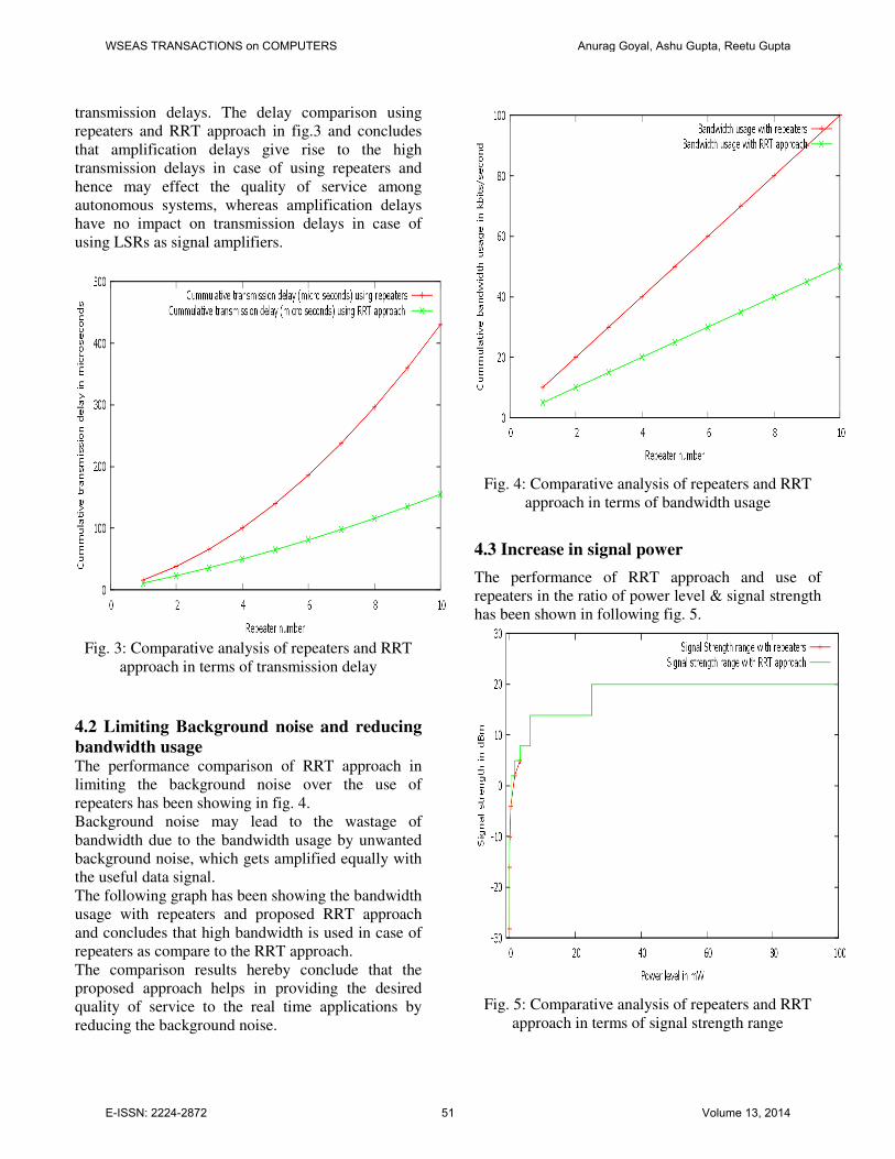
transmission delays. The delay comparison using
repeaters and RRT approach in fig.3 and concludes
that amplification delays give rise to the high
transmission delays in case of using repeaters and
hence may effect the quality of service among
autonomous systems, whereas amplification delays
have no impact on transmission delays in case of
using LSRs as signal amplifiers.
Fig. 3: Comparative analysis of repeaters and RRT
approach in terms of transmission delay
4.2 Limiting Background noise and reducing
bandwidth usage The performance comparison of RRT approach in
limiting the background noise over the use of
repeaters has been showing in fig. 4.
Background noise may lead to the wastage of
bandwidth due to the bandwidth usage by unwanted
background noise, which gets amplified equally with
the useful data signal.
The following graph has been showing the bandwidth
usage with repeaters and proposed RRT approach
and concludes that high bandwidth is used in case of
repeaters as compare to the RRT approach.
The comparison results hereby conclude that the
proposed approach helps in providing the desired
quality of service to the real time applications by
reducing the background noise.
Fig. 4: Comparative analysis of repeaters and RRT
approach in terms of bandwidth usage
4.3 Increase in signal power
The performance of RRT approach and use of
repeaters in the ratio of power level & signal strength
has been shown in following fig. 5.
Fig. 5: Comparative analysis of repeaters and RRT
approach in terms of signal strength range
WSEAS TRANSACTIONS on COMPUTERS Anurag Goyal, Ashu Gupta, Reetu Gupta
E-ISSN: 2224-2872 51 Volume 13, 2014

The performance of RRT approach and use of
repeaters in the ratio signal strength & distance travel
has been shown in fig. 6.
Fig. 6: Comparative analysis of repeaters and RRT
approach in terms of distance travel in inches
One the basis of graphs seen in fig. 5 and fig. 6, it has
been concluded that signal may travel larger
distances using RRT approach as compare to
repeaters.
4.4 Avoiding users moving to larger distances As discussed in earlier section, the use of repeaters
may move the users virtually to the longer distances
due to repeater delay and delay of RF signal in the
air. The radio distance thus becomes much larger
than the real distance, which may affect the quality of
service among autonomous systems separated
through larger distances.
The use of RRT approach may resolve this issue due
to absence of repeater delay and RF signal delay in
label switched routers being used instead of
repeaters.
The performance comparison of usage of repeaters
and RRT approach in terms of radio distances has
been shown in fig. 7 and it has been concluded that
RRT approach does not move the users to the larger
distances and hence retain the quality of service
among autonomous systems.
Fig. 7: Comparative analysis of repeaters and RRT
approach in terms of radio distances
4.5 Improper Repeater support The performance comparison of usage of repeaters in
terms of successful transmission rate has been
presented in the graph seen in fig. 8 and concludes
that RRT approach achieves desired QoS.
Fig. 8: Comparative analysis of repeaters and RRT
approach in terms of radio distances
WSEAS TRANSACTIONS on COMPUTERS Anurag Goyal, Ashu Gupta, Reetu Gupta
E-ISSN: 2224-2872 52 Volume 13, 2014
5 Conclusions and Future Work The proposed approach has addressed the networking
issues including signal strength retention, signal
amplification, internal delay, background noise
amplification, amplifier constraint, poor signal
generation, repeater support issues etc.
The proposed approach makes use of Relay Race
Transmission in MPLS technology to extend its QoS
performance among autonomous systems by the
means and methods using LSRs instead of signal
amplifiers between remote distances.
The results presented in the earlier section conclude
that extended MPLS technology has an edge over the
default MPLS technology in terms of maintaining
desired signal strength among autonomous systems
and hence providing QoS among ASs. In future, researchers may identify additional
QoS metrics which may further help in
providing quality of service in wireless
networks.
Acknowledgement This research paper is made possible through the help
and support from everyone, including: Dean (R&C)
& other Officials/Authorities of Punjab Technical
University, Kapurthala, my Supervisor- Dr. Ashu
Gupta, and in essence, all sentient beings.
References [1] Giles, C.R., Desurvire, E., Propagation of
signal and noise in concatenated erbium-
doped fiber optical amplifiers, Journal of
Lightwave Technology, Vol. 22, 2002, pp.
147 – 154.
[2] Cox, D.C., Linear Amplification with
Nonlinear Components, IEEE Transactions
on Communications, 2003.
[3] Bumjae Shin, Jeonghyeon Cha ; Jangheon
Kim ; Woo, Y.Y., Linear power amplifier
based on 3-way Doherty amplifier with
predistorter, Microwave Symposium Digest,
Vol.3, 2004,pp. 2027 – 2030.
[4] Kiyoshi Fukuchi, Tadashi Kasamatsu, Masao
Morie, Risato Ohhira, Toshiharu Ito, Kayato
Sekiya, Daisaku Ogasahara, Takashi Ono,
10.92-Tb/s (273 x 40-Gb/s) triple-band/ultra-
dense WDM optical-repeatered transmission
experiment, Optical Fiber Communication
Conference, Anaheim, California
2001
[5] Banyamin, B.Y., Berwick, M., Analysis of
the performance of four-cascaded single-
stage distributed amplifiers, IEEE
Transactions on Microwave Theory and
Techniques, Vol.48,2002, pp. 2657 – 2663
[6] Hyunchul Ku, Kenney, J.S., Behavioral
modeling of nonlinear RF power amplifiers
considering memory effects, IEEE
Transactions on Microwave Theory and
Techniques, Vol. 51, 2003, pp. 2495 – 2504
[7] Raab, F.H., Asbeck, P., Cripps, S.,
Kenington, P.B., Power amplifiers and
transmitters for RF and microwave, IEEE
Transactions on Microwave Theory and
Techniques, Vol. 50, 2002, pp. 814-826
[8] Aleksic, S., Analysis of Power Consumption
in Future High-Capacity Network Nodes,
IEEE/OSA Journal of Optical
Communications and Networking, Vol.1,
2009, pp. 245 - 258 [9] Wu, S., Razavi, B., A 900-MHz/1.8-GHz
CMOS receiver for dual-band applications,
IEEE Journal of Solid-State Circuits, Vol.
33, 2002, pp. 2178 – 2185 [10] Sameh, A., Wagh, S., Salama, Q., Dealing
with Quality of Service in Hybrid Wired-
Wireless Networks, Network Applications
Protocols and Services (NETAPPS) Second
International Conference, Kedah, 2010
[11] Jimaa, S., Kok Keong Chai, Yue Chen,
Alfadhl, Y., LTE-A an overview and future
research areas, IEEE 7th International
Conference on Wireless and Mobile
Computing, Networking and
Communications (WiMob), Wuhan, 2011.
[12] Pedrola, O. , Castro, A. , Velasco, L., Ruiz,
M., Fernández-Palacios, J. P., Careglio, D.,
CAPEX Study for a Multilayer IP/MPLS-
Over-Flexgrid Optical Network, Journal of
Optical Communications and Networking,
Vol. 4, 2012, pp. 639-650.
[13] Tanvir, M., Said, A.M., Decreasing packet
loss for QoS sensitive IP traffic in DiffServ
enabled network using MPLS TE,
International Symposium in Information
Technology (ITSim), Kuala Lumpur, 2010
Abbreviations QoS- Quality of Service AS-Autonomous system
RRT-Relay Race Transmission LSR- Label Switched Router
MPLS- Multiprotocol Label Switching LER-Label Edge Router
dBm-Power ratio in decibel MW-Mega Watt
WSEAS TRANSACTIONS on COMPUTERS Anurag Goyal, Ashu Gupta, Reetu Gupta
E-ISSN: 2224-2872 53 Volume 13, 2014