Embed Size (px)
Citation preview

BID #42-15 INDEX
ADDENDUM NO.6
EXTENSION OF CONSTITUTION BOULEVARD WEST
SHELTON, CONNECTICUT
City of Shelton Bid #42-15
INDEX TO PROJECT MANUAL
DIVISION 01 - BIDDING REQUIREMENTS
Invitation To Bid
Instructions To Bidders
Bid Form
Statement of Bidders Qualifications
Non-Collusion Affidavit
Form of Surety Guarantee and Bid Bond
Notification to Bidders
Department of Economic and Community Development – Contract Compliance Data Form
Contractor’s MBE Utilization Form
Affidavit
DIVISION 02 – CONTRACT DOCUMENTS
Agreement
Performance Bond and Labor and Material Bond
DIVISION 03 – TECHNICAL SPECIFICATIONS
Introduction To Technical Specifications
Contract Time and Liquidated Damages
Notice To Contractor – Bidding
Notice To Contractor – Permits
Notice To Contractor – Prevailing Wage Rates
Notice To Contractor – Excavation
Notice To Contractor – Excess Excavated Materials Management
Notice To Contractor – Utility Work
BID #42-15 INDEX
ADDENDUM NO.6
Notice To Contractor – Protection of Underground Utilities
Notice To Contractor – Utility Informational Plan Sheets
Notice To Contractor – Utility Specifications
Notice To Contractor – Salvage Materials
Notice To Contractor – Fire Department, Police and Emergency Medical Services
Notice To Contractor – Traffic Signals
Notice To Contractor – Recent Revisions
Notice To Contractor – Portland Cement Concrete (PCC) Mix Classifications
Notice To Contractor – Sanitary Sewer
Notice To Contractor – Sign Inventory
Notice To Contractor – Global Positioning System (GPS) Coordinates for Signs
Notice To Contractor – Manhole Frame and Cover
Notice To Contractor – Increased Requirements for Construction Field Office
Notice To Contractor – 9.49 – Furnishing, Planting and Mulching Trees, Shrubs,
Vines and Ground Cover Plants
Notice To Contractor – Quality Control Program
Section 1.05 – Control of the Work
Section 1.06 – Control of Materials
Section 1.07 – Legal Relations and Responsibilities
Section 1.07 – Legal Relations and Responsibility to Public
Section 1.08 – Prosecution and Progress
Section 10.06 – General Clauses for Highway Illumination and Traffic Signal Project
ITEM #0202119A – Rock Excavation (Controlled Blasting)
ITEM #0202452A – Test Pit
ITEM #0205003A – Trench Excavation 0’-10’ Deep
ITEM #0205092A – Coordination and Backfilling For Utility Installation
ITEM #0219011A – Sedimentation System at Catch Basin
ITEM #0219021A – Stormwater Detention Basin (Site No. 1)
ITEM #0219022A – Stormwater Detention Basin (Site No. 2)
ITEM #0406999A – Asphalt Adjustment Cost
ITEM #0507171A – Hydrodynamic Separator (Site No. 1)
BID #42-15 INDEX
ADDENDUM NO.6
ITEM #0601445A – Embankment Wall (Site No. 1)
ITEM #0601446A – Embankment Wall (Site No, 2)
ITEM #0950013A – Erosion Control Matting
ITEM #0950019A – Turf Establishment – Lawn
ITEM #0969054A – Contractor Quality Control Program Level 1
ITEM #0969064A – Construction Field Office, Large
ITEM #0971001A – Maintenance and Protection of Traffic
ITEM #0979004A – Construction Barricade Detectable
ITEM #1002201A – Traffic Control Foundation – Span Pole
ITEM #1008015A – 2” Rigid Metal Conduit – Surface
ITEM #1008115A – 2” Rigid Metal Conduit in Trench
ITEM #1008117A – 3” Rigid Metal Conduit in Trench
ITEM #1008215A – 2” Rigid Metal Conduit Under Roadway
ITEM #1008908A – Clean Existing Conduit
ITEM #1010002A – Handhole
ITEM #1017032A – Service (Metered)
ITEM #1102002A – 8’ Aluminum Pedestal
ITEM #1103023A – 32’ Steel Span Pole
ITEM #1103024A – 34’ Steel Span Pole
ITEM #1114102A – Span Wire
ITEM #1105003A – 1 Way, 3 Section Span Wire Traffic Signal
ITEM #1105007A – 2 Way, 3 Section Span Wire Traffic Signal
ITEM #1105180A – 1 Way, 1 Section Bi-Colored Arrow
ITEM #1105303A – 1 Way, 3 Section Pedestal Mounted Traffic Signal
ITEM #1107011A – Accessible Pedestrian Signal and Detector (Type A)
ITEM #1108115A – Full Actuated Controller 8 Phase
ITEM #1111201A – Temporary Detection (Site No. 1)
ITEM #1112284A – Vehicle Detector Monitor
ITEM #1112286A – 360 Degree Camera Assembly
ITEM #1112287A – 360 Degree Video Detection Processor
ITEM #1113725A – 24 AWG 4 Twisted Pair Category 6 Cable
BID #42-15 INDEX
ADDENDUM NO.6
ITEM #1118012A – Removal and Relocation of Traffic Signal Equipment
ITEM #1118051A – Temporary Signalization (Site No. 1)
ITEM #1208931A – Sign Face – Sheet Aluminum (Type IX Retroreflective Sheeting)
Water Main Sewer Special Provisions
ITEM #1300015A – Rock in Trench Excavation 0’-10’ Deep
ITEM #1300151A – Additional Backfill Material (Water Main)
ITEM #1301084A – 12” Ductile Iron Pipe (Water Main)
ITEM #1301862A – Furnish Pipe, Valves and Miscellaneous Fittings (Water Main)
ITEM #1301900A – Hydrostatic Pressure Test
ITEM #1302229A – 12” X 16” Tapping Sleeve and Valve
ITEM #1302901A – Air Relief Valve (Water Main)
ITEM #1303202A – Hydrant Assembly (Water Main)
ITEM #1304111A – Class “C” Concrete (Water Main)
Sanitary Sewer Special Provisions
ITEM #1400102A – 8” Polyvinyl Chloride Pipe (Sanitary Sewer)
ITEM #1400104A – 12” Polyvinyl Chloride Pipe (Sanitary Sewer)
ITEM #1403001A – Manhole (Sanitary Sewer)
ITEM #1403007A – Special Sanitary Manhole
Appendix A – Aquarion Water Company Standard Technical Specifications for Pipeline Projects

DIVISION 03
Rev. 11-21
BID #42-15 GENERAL
ADDENDUM NO.6
OCTOBER 2021
BID #42-15
EXTENSION OF CONSTITUTION BOULEVARD WEST
City of Shelton
The State of Connecticut, Department of Transportation, Standard Specifications for
Roads, Bridges, Facilities and Incidental Construction, Form 818, 2020, as revised by the
Supplemental Specifications dated July 2021 (otherwise referred to collectively as "ConnDOT
Form 818") is hereby made part of this contract, as modified by the Special Provisions contained
herein. Form 818 is available at the following DOT website link
http://www.ct.gov/dot/cwp/view.asp?a=3609&q=430362.
The current edition of the State of Connecticut Department of Transportation's
"Construction Contract Bidding and Award Manual" ("Manual"), is hereby made part of this
contract. If the provisions of this Manual conflict with provisions of other Department
documents (not including statutes or regulations), the provisions of the Manual will govern. The
Manual is available at the following DOT website link
http://www.ct.gov/dot/cwp/view.asp?a=2288&q=259258. The Special Provisions relate in
particular to the Extension of Constitution Boulevard West in the City of Shelton.
Within the CDOT – Form 818 Standard Specifications and wherever the following terms are
used they shall mean, respectively:
CDOT – Form 818 or Contract
Documents term
Meaning Herein
State, Department, Commissioner
Owner (City of Shelton) or Local Public Agency
Engineer or Architect
Owner, City Engineer
or its representatives
Inspector
Representative of Owner, Local Public Agency or other
duly authorized representative
Laboratory Laboratory designated by the Engineer or Owner
All work under this contract shall follow and be constructed in conformance with CDOT – Form
818 except as amended herein.
1 Local Public Agency (ies): Local Regulatory Agency (ies) shall be defined as the governing
body or authority having jurisdiction over or responsibility for a particular activity within the
scope of this Contract. They may be as specifically defined within the Special Conditions,
otherwise, the Contractor shall be responsible to determine same in the local area of the Contract.
2 Further, it is provided that whenever anything is, or is to be, done if, as, or, when, or where
"contemplated, required, determined, directed, specified, authorized, ordered, given, designated,
Rev. 11-21
BID #42-15 GENERAL
ADDENDUM NO.6
indicated, considered necessary, deemed necessary, permitted, reserved, suspended, established,
approval, approved, disapproved, acceptable, unacceptable, suitable, accepted, satisfactory,
unsatisfactory, sufficient, insufficient, rejected, or condemned," it shall be understood as if the
expression were followed by the words "by the Owner" or "to the Owner."
CONTRACT TIME AND LIQUIDATED DAMAGES
Phase 1
Three-hundred and sixty ( 360 ) calendar days will be allowed for completion of the work
on this Contract and the liquidated damages charge to apply will be One-thousand five hundred
Dollars ($1,500) per calendar day.
Phase 2
One-hundred and eighty ( 180 ) calendar days will be allowed for completion of the work
on this Contract and the liquidated damages charge to apply will be One-thousand five hundred
Dollars ($1,500) per calendar day.

Rev. 11/21
BID #42-15 GENERAL
ADDENDUM NO.6
NOTICE TO CONTRACTOR –PERMITS
The Contractor is hereby notified that several permits have been acquired and shall be obtained
for the work. The Contractor shall abide by all permit conditions and requirements.
The following permits have been acquired:
Pending permits include:
City of Shelton Planning and Zoning Commission – Site Plan Approval.
City of Shelton Inland Wetlands Commission – Site Plan Approval
CTDEEP - General Permit for Construction Activities
The Contractor is responsible for securing all other permitting, including the encroachment
permit form CTDOT District 3.
Rev. 11/21
BID #42-15 GENERAL
ADDENDUM NO.6
NOTICE TO CONTRACTOR –PREVAILING WAGE RATES
The Contractor is hereby notified that they shall pay prevailing wage rates as defined elsewhere
in these Contract Documents and as required by the Connecticut Statutes. The Contractor shall
be responsible for paying those prevailing wage rates in effect at the time of construction.
Rev.11/21
Bid #42-15 GENERAL
ADDENDUM NO.6
NOTICE TO CONTRACTOR –EXCESS EXCAVATED MATERIALS MANAGEMENT
Suitable materials excavated for the Project shall be blended and reused for various project materials such as
fill, processed aggregate base or subbase if suitable.
Excess materials, with the approval of the Engineer, may be deposited on the Mas Property where shown on
the Site Preparation Plan in safe, stable piles. Materials stored on the Mas Property shall be crushed so that
the maximum stone size is no greater than 12”. Materials deposited on the Mas Property will become the
property of the City. There will be no compensation for any costs required to access the Mas Property such
as clearing operations, haul roads etc.
The Contractor may haul any materials off-site for their use, there will be no additional payment made for
hauling or disposing of materials and no payment to import materials for borrow and fill operations.

Rev. 11/21
BID #42-15 ITEM #0202119A
ADDENDUM NO.6
ITEM #0202119A - ROCK EXCAVATION (CONTROLLED BLASTING)
Description: Controlled blasting shall consist of furnishing all labor, equipment, materials and services, and performing operations required to fragment rock utilizing controlled blasting techniques such that damage is prevented to adjacent structures, utilities, property and such that resulting ground vibrations and air blast overpressures are maintained below the specified maximum levels. The Contractor shall protect existing adjacent property and structures, workers, Engineer, and the general public from damage or injury from improper handling of explosives, fly rock, excessive round vibrations and/or excessive air blast overpressure levels.
The Contractor shall furnish, install and implement an audible warning system to indicate impending blasting and familiarize workers, Engineers, and the general public with the system implemented.
Applicable Standards and Provisions:
a. Applicable ordinances, codes, statutes, rules and regulations of the City of Shelton,
the State of Connecticut, and others having jurisdiction.
b. Occupational Safety and Health Administration, United States Department of
Labor Requirements.
c. ANSI "Safety Requirements for Construction and Demolition."
d. Applicable U.S. Treasury Department, Bureau of Alcohol, Tobacco and Fire Arms
regulations.
e. NFPA - Code for the Manufacture, Transportation, Storage, and use of Explosive
Materials.
Quality Assurance:
a. Seismic Survey Firm: Company specializing in seismic surveys with 3 years
documented experience.
b. Explosives Firm: Company specializing in explosives for disintegration of
subsurface rock with 3 years documented experience. Personnel will be required
to demonstrate experience.
Submittals:
a. The Contractor shall submit to the Engineer and the Fire Marshall, for approval, at
least two weeks prior to conducting blasting operations a Blasting Plan with a
complete description of their proposed plans and methods of blasting prior to
proceeding with the work. b. Indicate proposed methods of blasting, delay pattern, explosive types, type of blasting
mat or cover, and intended rock recovery method.
c. Provide diameter, spacing, burden, depth, pattern, and inclination of blast holes.
d. Provide type, strength, amount in terms of weight and cartridges of explosives to be used
in each hole, on each delay and the total for the blast.
e. Provide the distribution of the charge in the holes and the priming of each hole.
f. Provide type, sequence and number of delays, delay pattern; wiring diagram for blast;
size and type of hookup lines and lead lines; type and capacity of firing source; type, size
and location of safety switches, lightning gaps.
Rev. 11/21
BID #42-15 ITEM #0202119A
ADDENDUM NO.6
g. Provide stemming of holes and matting or covering of blast area.
h. Provide best estimate of gradation of resulting blast rock.
i. Provide projected vibrations versus distance to the property line and adjacent structures.
j. Provide qualifications of the person or persons at the site who will be directly responsible
for supervising the loading of the shot and for firing it.
k. Provide written qualifications of seismic survey firm. l. Provide written qualifications of explosives firm.
m. As part of the Engineer’s review of the Contractor's Blasting Plan, the Engineer
will designate a test area of rock excavation to which the Contractor will confine
his initial drilling and blasting operation. No additional drilling or blasting will be
performed until the Engineer's examination of the blasting effects has been
completed and the original plan of operations reaffirmed or revised in writing,
based on the Engineer's review.
Project Record Documents: a. Submit two copies of project records and drawings.
b. Complete, maintain and submit permanent blast reports including logs of each blast.
Include, as a minimum;
1. Date, exact firing time and limits of blast, by elevation and column location.
2. Name of person in responsible charge; blasting permit number.
3. Unusual joint or seam conditions encountered in the rock.
4. Type and strength of explosives, blasting caps, and distribution of delay
periods used.
5. Total explosive loadings per round and per group of delays.
6. On a diagram of the approved test pattern, indicate any holes not drilled,
drilled but not loaded, changes in spacing or in pattern of delays or in
loading of holes.
7. Prevailing weather conditions, including direction and approximate velocity
of wind, atmospheric temperature, relative humidity and cloud conditions
at the time of blast.
8. Comments by blaster in charge regarding any misfires, unusual results or
effects.
9. An evaluation of the blast indicating tights, areas of significant overbreak
and any recommended adjustments for the next blast.
10. Signature and title of person at the site making record entries.
c. Submit summary of complaints.
Complaints: a. Report all blasting complaints to the Owner’s Representative within 24 hours of receipt
thereof. Include the name, address, date, time received, date and time of blast
complained about, and a brief description of the alleged damages or other circumstances
upon which the complaint is predicated. Assign each complaint a number, and number
all complaints consecutively in order of receipt.
b. Submit a summary report to the Owner’s Representative each month which indicates the
date, time and name of person investigating the complaint, and the amount of settlement,
if any.
c. When settlement of a claim is made, furnish the Owner’s Representative with a copy of
the release of claim by the claimant.
d. Immediately notify the Owner’s Representative, throughout the statutory period of
liability, of any formal claims or demands made by attorneys on behalf of claimants, or of

Rev. 11/21
BID #42-15 ITEM #0202119A
ADDENDUM NO.6
serving of any notice, summons, subpoena, or other legal documents incidental to
litigation, and of any out-of-court settlement or court verdict resulting from litigation.
e. Immediately notify the Owner’s Representative of any investigations, hearings, or
orders received from any Governmental agency, board or body claiming to have
authority to regulate blasting operations.
Project Conditions:
a. When blasting is found necessary for removal of rock, the Contractor shall take all
reasonable precautions for the protection of individuals and property exposed to his
operations. Explosives shall be stored, handled and employed in accordance with
Federal, State and local regulations.
b. Protect nearby structures from damage. All construction induced damage shall be
repaired by the Contractor at no additional expense to the Owner.
c. Perform blasting work only during the hours permitted by ordinances of the City of
Shelton, Connecticut.
d. The amount of vibration and overpressure generated by blasting shall not exceed
those specified by regulatory statutes or directives establish by State, Town or other
authorities. In no case shall the peak particle velocity generated by blasting exceed
2.0 inch per second at 40 Hz as measured at the property line or exceed the
recommended values in U.S. Bureau of Mines report RI-8507, Nov. 1980. The
measured overpressures generated by blasting shall not exceed 130 decibels at the
property line. However, it is the contractor’s responsibility to control vibrations
and overpressures to whatever lower limits are necessary to protect adjacent
properties and persons.
e. Protect new concrete
1. Do not blast within 25 feet of concrete less than 5 days old.
2. Limit peak particle velocity from blasting to less than the following limits:
Elapsed Time After
Pouring
Maximum Peak Particle
Velocity
0 to 2 Hours 1 inch per second
2 to 24 Hours 0.5 inch per second
24 to 72 Hours 1 inch per second
more than 72 Hours 2 inches per second
Materials:
a. Rock (Definition): Solid mineral material with a volume in excess of 2 cu yd. in open
areas and 1 cu yd. in trenches or solid material that cannot be removed with a 3/4 cu
yd. capacity power shovel without drilling or blasting.
b. Control Blasting (Definition): Excavation of rock in which various elements of the
blast (hole size, depth, spacing, burden, charge size, distribution, delay sequence) are
carefully balanced and controlled to provide a distribution of charge that will
disintegrate rock to the required contours with as uniform a surface as possible to
minimize overbreak and fracturing of rock beyond the contour line.

Rev. 11/21
BID #42-15 ITEM #0202119A
ADDENDUM NO.6
c. Explosives: Type recommended by explosives firm and required by authorities having
jurisdiction.
d. Delay Devices: Type recommended by explosives firm.
e. Blasting Mat Materials: Type recommended by explosives firm
f. Stemming Materials: Type recommended by explosives firm.
Construction Methods:
General Blasting Procedures: The time during which explosives may be used is restricted to Monday through Friday between the hours of 9:00 A.M. and 3:00 P.M. (or prevailing time), and subject to other time limitations as may be required by the City of Shelton. The use of explosives is not permitted on weekends (Saturday and Sunday), holidays, on the eve of a holiday nor between the hours of 3:00 P.M. and 9:00 A.M., unless approved in writing by the Engineer. In order to minimize traffic disruptions, the Contractor shall schedule blasting such that any two successive blasts detonated anywhere on the project are separated by at least 2 hours. The Contractor's blasting operations shall be performed using extreme care to minimize the inconvenience and interruption to traffic and damage to the pavement, structures, and surrounding areas.
Preparation:
a. Verify site conditions and note irregularities affecting work of this Section.
b. As a minimum, perform preconstruction surveys of adjoining structures on properties
to the site within the zone of influence of the blasting.
c. Obtain appropriate permissions to perform preconstruction surveys.
d. Provide certificate of suitable insurance coverage.
e. Beginning work of this Section means acceptance of existing conditions.
Rock Excavation – Mechanical Method:
a. Excavate for and remove rock by the mechanical method.
b. Cut away rock at excavation bottom to form level bearing.
c. Remove loose rock to provide sound and unshattered base for foundations.
d. Remove excavated material from site or stockpile for use in other parts of project.
e. Correct unauthorized rock removal by placing compacted granular fill, crushed stoned
and/or lean concrete, as directed by the Engineer.
Rock Excavation – Controlled Blasting Methods:
a. Advise owners of adjacent buildings or structures in writing prior to setting up
seismographs. Describe blasting and seismic operations.
Rev. 11/21
BID #42-15 ITEM #0202119A
ADDENDUM NO.6
b. Obtain a seismic survey during test blast program prior to rock excavation to
characterize vibration transmission characteristics and to determine maximum charges
that can be used at different locations in area of excavation without damaging adjacent
properties.
c. Provide seismographic monitoring during progress of blasting operations at two 2
locations minimum. As a minimum, each blast shall be monitored as follows:
1. Vibrations shall be monitored at the property line nearest to the blasting
area, and on the ground surface adjacent to the nearest structure. When so
directed by the Engineer, vibrations shall also be monitored adjacent to
freshly placed concrete.
2. Overpressures and vibrations shall be continuously monitored along the
property line along the southern portion of the site (residential parcels) and
as directed by the Engineer.
3. The Contractor shall verbally report vibration/overpressure monitoring
results to the Engineer within two hours of blasting and shall provide written
reports of monitoring results to the Owner’s Representative and Engineer
within 24 hours of blasting.
d. Use controlled blasting techniques to reduce overbreak to a minimum and keep
vibrations and noise within specified limits.
e. Disintegrate rock and remove from excavation.
f. Cut away rock at excavation bottom to form level bearing.
g. Remove shattered layers to provide sound and unshattered base for foundations.
h. Remove excavated material from site or stockpile for use in other parts of project, as
directed elsewhere in the Contract Documents.
i. Correct unauthorized rock removal by placing compacted granular fill, crushed stone
and/or lean concrete, as directed by the Engineer at no cost to owner.
Field Quality Control:
a. Provide for the Engineer visual inspection of slopes to remain, bearing surfaces, and
cavities formed by removed rock.
b. Blasting may be additionally monitored for vibration and/or air overpressure by the
Engineer. Monitoring performed by the Engineer does not relieve the Contractor of his
responsibility for vibration and overpressure monitoring.
c. Coordinate all blasts with the Owner’s Representative and Engineer.
d. When vibrations or noise exceed specified limits, reduce size of loads, use additional
millisecond delays, or take other appropriate measures as necessary to satisfy vibration
and overpressure requirements.

Rev. 11/21
BID #42-15 ITEM #0202119A
ADDENDUM NO.6
Method Of Measurement: Where “Rock Excavation (Controlled Blasting)” is called for on the plans, it will be measured for payment by the actual number of cubic yards of rock removed. The Contractor shall strip the rock of sufficient overlaying material to allow for proper measurement. No payment will be made for overblasted rock left in place. The cubic yard price includes the detailed blasting program, cushion blasting, line drilling, blast monitoring, pre-blast and post- blast surveys, permits and all other work. As a minimum, rock shall be removed as follows:
a. Limits of foundation concrete shown on plans plus 12 inches outside vertical
concrete lines and 12 inches below the base.
b. Paved areas to the underside of sub-base.
c. Lawns and planting areas to 24 inches below finished grade.
Presplitting necessary to provide an acceptable ledge face will not be measured for payment but shall be included in the cost of Rock Excavation (Controlled Blasting). The detailed Blasting Plan, cushion blasting, line drilling, blast monitoring, pre and post blast surveys, permits and other work to perform the rock removal will not be measured for payment but shall be included in the cost of Rock Excavation (Controlled Blasting). Rock removed for the installation of utilities shall be measured and paid for as Rock Excavation in Trench 0’-10’ Deep. Rock for utility trenches shall be measured and paid for to a depth of 6 inches below the bottom of the pipe or duct structure and 24 inches wider than the pipe diameter or the duct structure width.
Basis Of Payment:
This work will be paid for at the contract unit price per cubic yard for “Rock Excavation (Controlled Blasting)”. The price shall include all equipment, tools and labor necessary to complete the work, dispose of the excavated material. No separate payment will be made for the detailed blasting program, cushion blasting, line drilling, blast monitoring, pre-blast and post- blast surveys, presplitting, profiling, permits and all other labor incidental thereto. Pay Item Pay Unit Rock Excavation (Controlled Blasting) C.Y.
Rev. Date 11-21
BID #42-15 ITEM #0205092A
ADDEDNDUM NO.6
ITEM #0205092A – COORDINATION AND BACKFILLING FOR UTILITY
INSTALLATION
Description: Work under this item shall consist of furnishing all equipment, tools, labor, and
materials to perform all work necessary for the coordination with the individual utility
companies to arrange for installation of their facilities by their forces after the Contractor
excavates the trench, furnishing bedding material, backfilling and satisfactory disposal of all
surplus materials, for the Gas Main, Electrical, Cable Television and
Telephone/Communications Systems according to their standards as shown on the plan and
typical section as detailed or as directed by the Engineer. Trench excavation of earth and rock
will be measured and paid for separately.
Materials: Bedding shall be according to the individual Utility Company standards, if Utility
Company does not have a published standard bedding material shall conform to Article 10.10.02;
bedding material shall all pass a 3/8” sieve, and not more that 10% passes a No. 200 sieve.
Borrow, when needed for backfill, shall conform to Article 2.07.02.
Construction Methods: Work shall conform to Article 10.01.03 supplemented with the
following: The Contractor shall furnish the bedding material at the trench and coordinate with
Utility Company forces for the placement in the trench. The Contractor shall complete the
backfilling after the bedding has been placed and approved by the Utility Company.
Where native material is not suitable to be used as backfill, the Contractor shall provide borrow
to serve as suitable backfill to the subgrade elevation.
Method of Measurement: This work will be measured for payment by the number of linear
feet of Coordination and Backfilling for Utility Installation completed and accepted in place by
the Engineer.
Basis of Payment: This work will be paid for at the contract unit price per linear feet of
Coordination and Backfilling, for the Utility Installation completed and accepted in place, which
price shall include all materials, equipment, tools, labor, and work incidental thereto. Trench
excavation of earth and rock will be measured and paid for separately.
Pay Item Pay Unit
Coordination and Backfilling for Utility Installation L.F.

Rev. Date 11-21
BID #42-15 ITEM #0601445A, #0601446A
ADDENDUM NO.6
ITEM #0601445A - EMBANKMENT WALL (SITE NO. 1)
ITEM #0601446A – EMBANKMENT WALL (SITE NO.2)
Description: This item will consist of designing, furnishing and constructing an embankment
retaining wall in the location, grades, and to the dimensions and details shown on the contract
drawings, and in accordance with these specifications.
Retaining Wall Selection: The Contractor shall select the proprietary embankment retaining
wall from the Department’s current approved list shown below. The Engineer will reject any
proposed retaining wall that is not listed below.
The following is a list of the proprietary embankment retaining walls for this project:
1. VERSA-LOK Harmony Retaining Wall
VERSA-LOK of New England
P.O. Box 6002
Nashua, NH 03063
(603) 883-3042
3. KeySystem I Retaining Wall
Keystone Retaining Wall Systems
13453 County Road 1
Fairhope, AL 36532
(251) 990-5761
2. MESA Retaining Wall System
TENSAR Earth Technology, Inc.
227 Ritter Road
Sewickley, PA 15143
(412) 749-9190
4. Pyramid Modular Blockwall
The Reinforced Earth Company
133 Park Street
North Reading, MA 01864
(978) 664-2830
5. Redi-Rock Retaining Wall-
Cobblestone Face Mold
Redi-Rock Walls-CT Division
68A South Canal Street
Plainville, CT 06062
(860) 793-6805
No other proprietary retaining walls will be allowed for this project.
This listing does not warrant that the individual walls can be designed to meet either the
dimensional, structural, or geotechnical constraints at each site.
Design:
1 - Design Computations: It is the Contractor's responsibility for the design, detailing
and additional construction specifications required to construct the wall. The actual designer of
the retaining wall shall be a qualified Professional Engineer licensed in the State of Connecticut.

Rev. Date 11-21
BID #42-15 ITEM #0601445A, #0601446A
ADDENDUM NO.6
2 - Designer's Liability Insurance: The Designer shall secure and maintain at no direct
cost to the Town, a Professional Liability Insurance Policy for errors and omissions in the
minimum amount of Five Hundred Thousand Dollars ($500,000). The designer may, at his
election, obtain a policy containing a maximum One Hundred Twenty Five Thousand Dollars
($125,000) deductible clause, but if he should obtain a policy containing such a clause, the
designer shall be liable to the extent of the deductible amount. The Designer shall obtain the
appropriate and proper endorsement to its Professional Liability Policy to cover the
indemnification clause in this contract as the same relates to negligent acts, errors or omissions in
the work performed by the Designer. The Designer shall continue this liability insurance
coverage for a period of three years from the date of the acceptance of the work by the agency
head as evidenced by a certificate of acceptance issued to the contractor or for three years after
the termination of the contract, whichever is earlier, subject to the continued commercial
availability of such insurance.
The designer shall supply the certificate of this insurance to the Engineer prior to the start
of construction of the wall. The designer's insurance company shall be licensed in the State of
Connecticut.
3 - Preliminary Submissions: Prior to the start of fabrication or construction, the
Contractor shall submit to the Engineer a design package, which shall include, but not be limited
to the following:
a. Detailed Plans:
Plan sheets shall be approximately 24" x 36"
Stamped by a licensed Professional Engineer (Connecticut).
Full plan view of the wall drawn to scale. The plan view must reflect
the horizontal alignment and offset from the horizontal control line to
the face of the wall. Beginning and ending stations, all utilities, signs,
lights, etc. that affect the construction along with all property lines and
easement lines adjacent to the wall shall be shown.
Full elevation view of the wall drawn to scale. Elevation views should
indicate the elevation at the top and bottom of walls, horizontal and
vertical break points, and the location of finished grade.
Typical cross sections drawn to scale including all appurtenances.
Detailed cross section should be provided at significant reinforcement
transitions such as wall ends.
Rev. Date 11-21
BID #42-15 ITEM #0601445A, #0601446A
ADDENDUM NO.6
Details of all wall components and their connections such as the
length, size and type of soil reinforcement and where any changes
occur; facing details; connections; etc.
Certified test reports indicating the connection strength versus normal
load relationship for the block-soil reinforcement connection to be
used.
Drainage details for embankment backfill including attachment to
outlets shown on contract drawings.
Details of any roadway drainage pipe projecting through the wall, or
any attachments to the wall. Details of the treatment of drainage
swales or ditches shown on the contract drawings.
Design parameters used along with AASHTO references.
Material designations for all materials to be used.
Wall to be similar appearance to similar to Versa-Lok “Harmony”
modular block with geogrid, “Allegheny Blend” color. Submit sample
for review and approval by City of Shelton during preliminary design.
An ornamental fence will be installed behind the retaining wall. Sono-
tubes for fence foundations will be set as backfill and geogrid are
being placed. Retaining wall design shall include details for wrapping
geogrid around sono-tubes and providing additional reinforcement,
where necessary. Details shall be specific to this installation and
match the ornamental fence submitted for this project, not generic
details.
Detailed construction methods including a quality control plan.
Construction quality control plans should include monitoring and
testing frequencies (e,g, for setting batter and maintaining horizontal
and vertical control). Construction restraints should also be listed in
the details. Specific requirements for construction around obstructions
should be included.
Details of installation of protective fencing where required.
Details of Architectural Treatment where required.
Details of Temporary Earth Retaining System(s) where required.
Rev. Date 11-21
BID #42-15 ITEM #0601445A, #0601446A
ADDENDUM NO.6
Details of wall treatment where the wall abuts other structures.
Treatment at underground utilities where required.
b. Design Computations:
Stamped by a licensed Professional Engineer (Connecticut).
Computations shall clearly refer to the applicable AASHTO provisions
as stated in the Notes on the Contract Drawings.
Documentation of computer programs including all design parameters.
c. Construction Specifications:
Construction methods specific to the proprietary retaining wall chosen.
These specifications should include construction limitations including
vertical clearance, right-of-way limits, etc. Submittal requirements for
materials such as certification, quality, and acceptance/rejection
criteria should be included. Details on connection of modular units
and connection of reinforcements such that assurance of uniform stress
transfer should be included.
Any requirements not stated herein.
The submissions for proprietary retaining walls shall be treated as working drawings
according to Section 1.05 amended as follows:
a. Six sets of each submission shall be supplied to the Town.
b. The Contractor shall allow 21 days for the review of each submission. If subsequent
submissions are required as a result of the review process, 21 days shall be allowed for review of
these submissions. No extensions in contract time will be allowed for the review of these
submissions.
4 - Final Submissions: Once a proprietary retaining wall design has been reviewed and
accepted by the Department, the Contractor shall submit the final plans. The final submission
shall include one set of full size (approximately 24" x 36") mylar sheets and five sets of full size
blue line copies. Submit electronic copies of final design plans and calculations in conjunction
with hard copies.
Rev. Date 11-21
BID #42-15 ITEM #0601445A, #0601446A
ADDENDUM NO.6
The final submission shall be made within 14 days of acceptance by the Town. No work
shall be preformed on the retaining wall until the final submission has been received by the
Town.
Acceptance of the final design shall not relieve the Contractor of his responsibility under
the contract for the successful completion of the work.
The actual designer of the proprietary retaining wall is responsible for the review of any
shop drawings prepared for the fabrication of the wall. One set of full size blue line copies of all
approved shop drawings shall be submitted to the Department's permanent records.
5 - General Design Requirements:
a. All designs for proprietary walls and temporary earth retaining systems shall conform
to the latest edition of the American Association of State Highway and Transportation Officials
(AASHTO) Standard Specifications for Highway Bridges and later interims published except as
noted otherwise herein:
b. The wall design shall follow the general dimensions of the wall envelope shown in the
contract plans.
c. The top of the concrete leveling pad shall be located at or below the theoretical
leveling pad elevation. The minimum wall embedment shall be two feet as measured to the top
of the leveling pad or as shown on the plans.
d. An even-elevation leveling pad is shown on the plans. If footing steps are required,
they shall be kept below the minimum embedment depth. Footing steps in addition to those
shown on the plans will be permitted at no additional cost to the Town.
e. The wall shall be designed to be within all property lines and easement lines shown on
the contract drawings. If additional work areas are necessary for the construction of the
proprietary retaining wall, the Contractor shall be responsible for obtaining the rights from the
affected property owners. Copies of these rights shall be forwarded to the Department.
f. The top of the wall shall be at or above the top of the wall elevations shown on the
plans. The top of the wall may be level or sloped to meet the top of the wall line noted.
g. Cast-in-place concrete will not be an acceptable replacement for areas noted by the
wall envelope, except for minor grouting of pipe penetrations.
h. The mechanical wall height for the purposes of design calculations shall be from the
top of the leveling pad to the top of the potential failure surface where the failure surface
intercepts the ground surface.
Rev. Date 11-21
BID #42-15 ITEM #0601445A, #0601446A
ADDENDUM NO.6
i. The minimum length of internal soil reinforcement shall be as specified in AASHTO
5.8.1, except for the minimum eight (8.0’) foot length requirement. Two four (4.0’) foot levels
of geogrid are shown on the plans.
i. If there are specific surcharges acting on the wall, they shall also be accounted for.
The minimum equivalent fluid pressure used to design the wall shall be 33 lbs./ft2 per linear foot
of wall.
j. The maximum allowable bearing capacity of the soil shall be assumed to be 4 ksf
unless otherwise shown on the plans. If additional soils information is required by the designer,
it must be obtained by the Contractor and will not be reimbursed by the Town.
k. For limit state allowable stress computations of extensible reinforcements, the
combined factor of safety for construction damage and environmental/aging effects shall not be
less than 1.75.
Materials: Materials shall conform to the following requirements and those not listed below
shall be as prescribed within the Standard Specifications for Roads, Bridges and Incidental
Construction, including supplemental specifications and applicable special provisions.
1 – Facing Block: The facing block can be precast or drycast concrete and shall be the
color specified on the plans, or as approved by engineer. The block shall meet the following
requirements:
a. Drycast Concrete:
i. The minimum compressive strength of the block shall be 4000 psi measured at 28
days.
ii. The maximum water absorption shall be less than five percent.
The Contractor shall submit to the Engineer a certified test report confirming the
compressive strength and water absorption conform to the requirements of ASTM C-140.
b. Precast Concrete: Shall conform to the requirements of Section M.03 and as follows:
i. The minimum compressive strength of the block shall be 4000 psi measured at 28
days.
ii. All precast concrete components shall be air-entrained composed of portland
cement, fine and coarse aggregates, admixtures and water. The air-entraining
feature may be obtained by the use of either air-entraining portland cement or an
approved air-entraining admixture. The entrained-air content shall be not less
than four percent or more than seven percent.
Rev. Date 11-21
BID #42-15 ITEM #0601445A, #0601446A
ADDENDUM NO.6
2 - Geosynthetic Soil Reinforcement: The minimum strength of the geosynthetic soil
reinforcement shall be based on experimental data. The Contractor shall submit to the Engineer
a certified test report confirming the strength of the material when tested according to the
methods specified in ASTM D5262 and extrapolated according to ASTM D2837 as outlined in
AASHTO Article 5.8.7.2.
3 – Metallic Soil Reinforcement: All soil reinforcement and structural connectors shall
be hot dipped galvanized according to the requirements of ASTM A123 (AASHTO M-111).
The minimum thickness of the galvanizing shall be based on the service life requirements in the
AASHTO Specifications.
Steel strip reinforcement shall be hot rolled to the required shape and dimensions. The
steel shall conform to AASHTO M223 (ASTM A572) Grade 65 unless otherwise specified.
Welded wire fabric reinforcement shall be shop fabricated from cold-drawn wire of the
sizes and spacings shown on the plans. The wire shall conform to the requirements of ASTM
A82, fabricated fabric shall conform to the requirements of ASTM A185.
4 - Metal Connectors: All metal hardware shall be hot dipped galvanized according to
the requirements of ASTM A123 (AASHTO M-111). The minimum thickness of the
galvanizing shall be based on the service life requirements in the AASHTO Specifications.
5 - Backfill Material: The material for backfill shall be Pervious Structure Backfill
conforming to the requirements of Articles M.02.05 and M.02.06.
6 - Facing Sealer: The face of all exposed drycast block shall be coated with clear
Penetrating Sealer Protective Compound conforming to the requirements of Article M.03.01-11.
Construction Methods: All construction methods for items not listed below shall be in
accordance with the detailed requirements prescribed for the construction of the several contract
items entering into the completed structure as specified in the Standard Specifications for Roads,
Bridges, and Incidental Construction.
1 - Installation: The foundation for the structure shall be graded level for a width equal to
or exceeding the length of the soil reinforcements, or as shown on the plans. If rock is
encountered in the excavation, it shall removed to provide a level area equal to or exceeding the
length of the soil reinforcements, but not greater than the pay limits shown on the plans.
Prior to wall construction, the foundation, if not in rock, shall be compacted as directed
by the Engineer. Any foundation soils found to be unsuitable shall be removed and replaced.
At each foundation level, an unreinforced concrete leveling pad shall be provided as
shown on the plans. The leveling pad shall have nominal dimensions of 6 inch thickness and 24
Rev. Date 11-21
BID #42-15 ITEM #0601445A, #0601446A
ADDENDUM NO.6
inch width, and shall be cast using minimum 2,000 psi 28-day compressive strength concrete.
The leveling pad shall be cast to the design elevations as shown on the plans. Allowable
elevation tolerances are +0.01 foot (1/8 inch), and -0.02 foot (1/4 inch), from the design
elevation.
The materials for the wall shall be handled carefully and installed in accordance with
manufacturer's recommendations and specifications. Special care shall be taken in setting the
bottom course of blocks to true line and grade.
All blocks above the first course shall interlock with the lower courses by means of
connecting pins. Vertical joints shall be staggered with each successive course as shown on the
working drawings. Vertical tolerances and horizontal alignment tolerances measured from the
face line shown on the plans shall not exceed ½ inch when measured along a 8-foot straightedge.
The overall tolerance of the wall from top to bottom shall not exceed ½ inch per eight feet of
wall height or one inch total, whichever is the lesser, measured from the face line shown on the
plans. A bond breaker shall be placed between the blocks and any adjacent cast-in-place
concrete.
2 - Backfilling: Backfill placement shall closely follow erection of each course of panels.
Backfill shall be placed in such a manner as to avoid any damage or disturbance to the wall
materials or misalignment of the facing panels. Any wall materials which become damaged or
disturbed during backfill placement shall be either removed and replaced at the Contractor's
expense or corrected, as directed by the Engineer. Any backfill material placed within the
reinforced soil mass which does not meet the requirements of this specification shall be corrected
or removed and replaced at the Contractor's expense.
Backfill shall be compacted to 95 percent of the maximum density as determined by
AASHTO T-99, Method C or D (with oversize correction, as outlined in Note 7).
The moisture content of the backfill material prior to and during compaction shall be
uniform throughout each layer. Backfill material shall have a placement moisture content less
than or equal to the optimum moisture content. Backfill material with a placement moisture
content in excess of the optimum moisture content shall be removed and reworked until the
moisture content is uniform and acceptable throughout the entire lift. The optimum moisture
content shall be determined in accordance with AASHTO T-99, Method C or D (with oversize
correction, as outlined in Note 7).
If 30 percent or more of the backfill material is greater than 19 mm in size, AASHTO T-
99 is not applicable. For such a material, the acceptance criterion for control of compaction shall
be either a minimum of 70 percent of the relative density of the material as determined by a
method specification provided by the wall supplier, based on a test compaction section, which
defines the type of equipment, lift thickness, number of passes of the specified equipment, and
placement moisture content.
Rev. Date 11-21
BID #42-15 ITEM #0601445A, #0601446A
ADDENDUM NO.6
The maximum lift thickness after compaction shall not exceed 10 inches, regardless of
the vertical spacing between layers of soil reinforcements. The Contractor shall decrease this lift
thickness, if necessary, to obtain the specified density. Prior to placement of the soil
reinforcements, the backfill elevation at the face shall be level with the connection after
compaction. From a point approximately three feet behind the back face of the panels to the free
end of the soil reinforcements the backfill shall be two inches above the attachment device
elevation unless otherwise shown on the plans.
Compaction within three feet of the back face of the panels shall be achieved by at least
three passes of a lightweight mechanical tamper, roller or vibratory system. The specified lift
thickness shall be adjusted as warranted by the type of compaction equipment actually used.
Care shall be exercised in the compaction process to avoid misalignment of the panels or damage
to the attachment devices. Heavy compaction equipment shall not be used to compact backfill
within three feet of the wall face.
At the end of each day's operation, the Contractor shall slope the last level of backfill
away from the wall facing to direct runoff of rainwater away from the wall face. The Contractor
shall control and divert runoff at the ends of the wall such that erosion or washout of the wall
section does not occur. In addition, the Contractor shall not allow surface runoff from adjacent
areas to enter the wall construction site.
Install sono-tubes behind wall for ornamental fence foundations as backfill and geogrid
are being placed. Retaining wall design shall include details for wrapping geogrid around sono-
tubes and providing additional reinforcement. Details shall be specific to this installation and
match the ornamental fence submitted for this project.
3 - Face Sealer: After the wall has been erected, the entire exposed face of the wall shall
be coated with Penetrating Sealer Protective Compound. The application of the sealer shall
conform to the requirements Article 8.18.03.
Several samples of the dry cast block shall be sealed prior to sealing the actual wall to
ensure that the sealer will not discolor the block. If the sealer does discolor the block, the
Contractor shall change to another approved supplier of sealer.
Method of Measurement: This work will be paid for on a lump sum basis and will not be
measured for payment.
Basis of Payment: This work will be paid for at the contract lump sum for "EMBANKMENT
WALL (SITE NO. X )", complete in place, which price shall include all work shown within the
pay limits shown on the plans for the retaining wall including but not limited to the following:
1. Design, detailing, and specifications for the wall.
2. Excavation for the wall

Rev. Date 11-21
BID #42-15 ITEM #0601445A, #0601446A
ADDENDUM NO.6
3. Design and Construction of temporary earth retaining systems
for the support of the slope during construction.
4. Construction of the Embankment Wall, including the
unreinforced concrete leveling pad.
5. The furnishing, placing and compacting of pervious structure
backfill within the maximum payment lines.
6. The furnishing and placing of backfill drainage systems for the
wall.
7. Any other work and materials shown on the plans for the
construction of the wall.
The price shall also include all materials, equipment, tools and labor incidental thereto.
If bedrock or large boulders (greater than one cubic yard) are encountered in the
excavation, the payment for it's removal will be made under the item "Structure Excavation -
Rock".
Rev. 11/21
BID #42-15 ITEM #1300015A
ADDENDUM NO.6
ITEM #1300015A – ROCK IN TRENCH EXCAVATION 0’ – 10’ DEEP
(WATER MAIN)
Description:
Work under this section shall include excavation, removal and disposal of all boulders 1/2 cubic
yard or greater in volume, rock removal, drilling and controlled blasting of boulders over 1 cubic
yard, ledge formations, hoe ramming, hand chipping, and cement masonry or concrete structures
to be removed from within the horizontal and vertical payment limits for pipe installation, as shown
on the Typical Trench Detail.
Work under this section shall include removal, by hand labor, if required, of ledge rock, boulders,
masonry or concrete structures in the vicinity of existing utilities.
Work under this section shall include pre-blast surveys, permits, drilling and blasting, excavation,
and disposal of the excavated rock and/or boulders.
Work under this section shall include furnishing and installing bedding material to replace
excavated rock to the limits shown on the Typical Trench Detail and compaction in 12” lifts of the
entire trench.
Work under this section does not include furnishing and placing of Additional Backfill Material
necessary to replace the excavated rock.
Definition of Rock
Rock shall be defined as solid ledge rock or boulders that, in the opinion of the Aquarion
Representative, require drilling and blasting, wedging or sledging, and barring for its removal.
The following material shall not be measured or allowed for payment as rock excavation:
soft or disintegrated rock or boulders which can be removed with a backhoe or excavator
bucket
loose or previously blasted rock
broken stone in rock fills, walls, or elsewhere
concrete, asphalt, or brick pavements
concrete, asphalt, or stone curbs
concrete, asphalt, or brick sidewalks
boulders one half (1/2) cu. yd. or less
Limits of Rock Excavation
Rock shall be excavated to maintain minimum clearance between the outside of the structure or
barrel of the pipe to the vertical side of the excavation, as shown by the horizontal payment limits
on the Typical Trench Detail. Isolated points of rock shall not come closer to the outside of the
structure or pipes and at joints as shown on the Typical Trench Detail for the purpose of
maintaining sufficient room for properly making the joint. Refer to the Typical Trench Detail for
Rev. 11/21
BID #42-15 ITEM #1300015A
ADDENDUM NO.6
the minimum distance between the bottom of the pipe, including the barrel, and rock at the bottom
of the trench. This is the vertical limit of payment for rock.
Rock in miscellaneous excavations shall be excavated in accordance with the directions and to the
limits directed by the Aquarion Representative.
The surface of the rock shall be stripped in sections satisfactory to the Aquarion Representative
before the rock is excavated so that the proper measurements can be made.
Rock shall be removed to a depth below the pipe shown on the Typical Trench Detail. Bedding
material shall be installed and compacted below the bottom of the pipe, and up to the vertical limits
for bedding material as shown on the Typical Trench Detail. Replacement of excavated rock in
this vertical limit for bedding material is considered bedding material, and is not considered as
Additional Backfill Material.
Materials:
Materials under this section include any tools or equipment necessary to excavate, remove, and
properly dispose of rock as defined in this section. Materials also include any tools or equipment
necessary to backfill and compact material to replace excavated rock.
Construction Methods:
Blasting
Explosives for blasting shall be stored, handled, and used in accordance with the laws, ordinances,
and regulations of the State of Connecticut and all local regulations and with such additional
regulations as the Aquarion Representative may require. Blasting shall be conducted so as not to
endanger persons or property and, unless otherwise permitted, shall be covered or otherwise
satisfactorily confined. The Contractor shall be responsible for and shall make good for any
damage caused by blasting or accidental explosions. If rock removal is required near existing
utility pipes, cables, or structures, the Contractor may be required to remove such rock without
blasting.
Mechanical Removal of Rock
Mechanical removal of rock shall include removal by hoe ram. The Contractor shall use
mechanical means for removal of rock for the following conditions:
due to the proximity of the pipeline route to existing structures
due to restrictions against blasting set by federal, state, or local officials, or
at the request of Aquarion
Rev. 11/21
BID #42-15 ITEM #1300015A
ADDENDUM NO.6
Frost Excavation
Frost excavation shall mean removal of frozen earth exceeding twelve (12) inches in depth,
which in the opinion of Aquarion, requires for its removal, drilling and blasting or breaking with
specialized power operated frost removal equipment.
Backfilling
Where pipe is laid in rock excavation, bedding material or Additional Backfill Material as specified
in these specifications, shall be placed over the rock and compacted to sub grade. The minimum
depth of bedding material as directed by the Owner’s Representative shall be in accordance with
the Typical Trench Detail. Excess rock, which cannot be used with earth to provide satisfactory
backfill in the upper portions of the trench, shall be disposed of the same as excess earth
excavation. No pieces of rock in excess of 12” shall be used in backfilling.
To replace excavated rock, the Contractor shall place backfill material obtained from excess
material from other portions of the work or Additional Backfill Material, as specified in these
specifications.
Additional Backfill Material shall be as directed by the Owner’s Representative.
Method of Measurement:
Rock In Trench Excavation will be measured for payment per cubic yard of rock, as defined in
this section, removed from the trench.
Bedding material furnished, installed, and compacted to replace excavated rock, to the limits
shown on the Typical Trench Detail, will not be measured separately for payment, but shall be
included in the linear foot cost of the pipe installation.
Additional Backfill Material furnished, installed, and compacted to replace excavated rock, to the
limits shown on the Typical Trench Detail, will be measured separately for payment under the
appropriate Item for Additional Backfill Material (Water Main).
Any cost beyond the unit prices for Rock Excavation for laborers and equipment that are idle
during periods of rock removal will not be measured separately for payment.
Basis of Payment:
Rock in Trench Excavation will be paid for at the contract unit price per cubic yard of rock, as
defined in this section, removed from the trench.
Rev. 11/21
BID #42-15 ITEM #1300015A
ADDENDUM NO.6
No separate payment will be made for bedding material furnished, installed, and compacted to
replace excavated rock, to the bedding material limits shown on the Typical Trench Detail.
Bedding material shall be included in the linear foot cost of the pipe installation.
Additional Backfill Material furnished, installed, and compacted to replace excavated rock, to the
limits shown on the Typical Trench Detail, will be paid for separately at the contract unit price
under the appropriate Item for Additional Backfill Material (Water Main).
No separate payment will be made for any cost beyond the unit prices for Rock Excavation for
laborers and equipment that are idle during periods of rock removal.
Pay Item Pay Unit
Rock In Trench Excavation 0’ – 10’ Deep CY
Rev. 11/21
BID #42-15 ITEM #1300151A
ADDENDUM NO.6
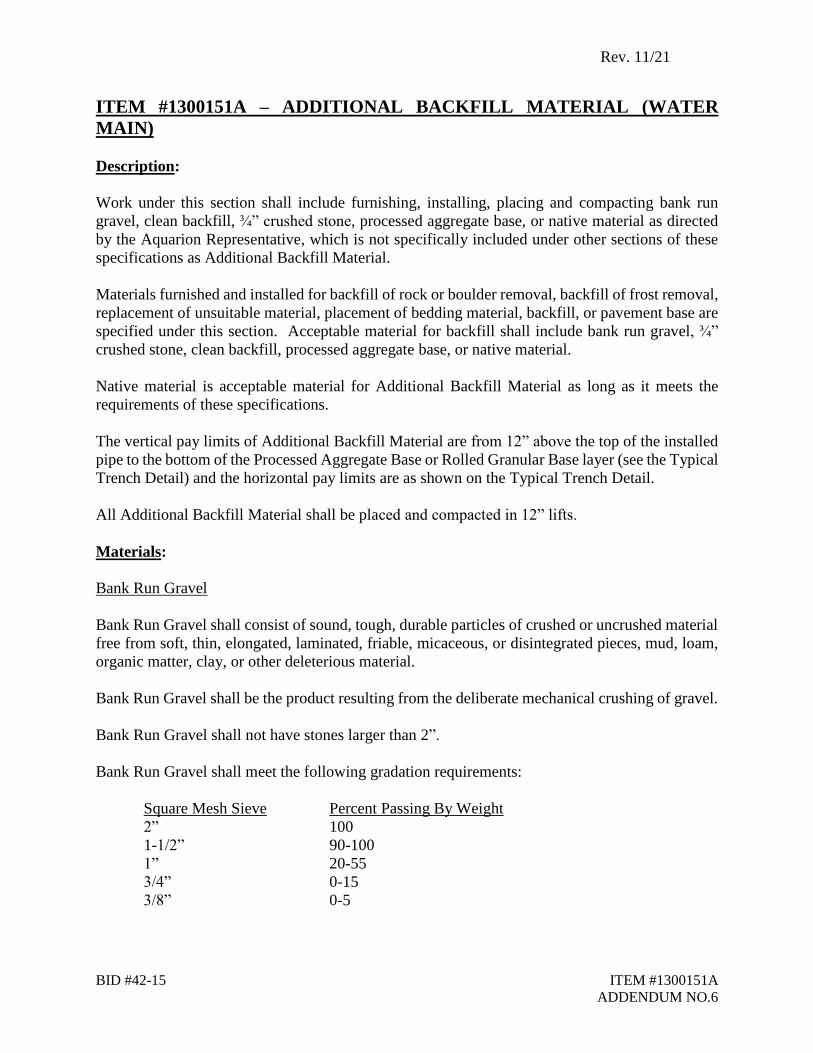
ITEM #1300151A – ADDITIONAL BACKFILL MATERIAL (WATER
MAIN)
Description:
Work under this section shall include furnishing, installing, placing and compacting bank run
gravel, clean backfill, ¾” crushed stone, processed aggregate base, or native material as directed
by the Aquarion Representative, which is not specifically included under other sections of these
specifications as Additional Backfill Material.
Materials furnished and installed for backfill of rock or boulder removal, backfill of frost removal,
replacement of unsuitable material, placement of bedding material, backfill, or pavement base are
specified under this section. Acceptable material for backfill shall include bank run gravel, ¾”
crushed stone, clean backfill, processed aggregate base, or native material.
Native material is acceptable material for Additional Backfill Material as long as it meets the
requirements of these specifications.
The vertical pay limits of Additional Backfill Material are from 12” above the top of the installed
pipe to the bottom of the Processed Aggregate Base or Rolled Granular Base layer (see the Typical
Trench Detail) and the horizontal pay limits are as shown on the Typical Trench Detail.
All Additional Backfill Material shall be placed and compacted in 12” lifts.
Materials:
Bank Run Gravel
Bank Run Gravel shall consist of sound, tough, durable particles of crushed or uncrushed material
free from soft, thin, elongated, laminated, friable, micaceous, or disintegrated pieces, mud, loam,
organic matter, clay, or other deleterious material.
Bank Run Gravel shall be the product resulting from the deliberate mechanical crushing of gravel.
Bank Run Gravel shall not have stones larger than 2”.
Bank Run Gravel shall meet the following gradation requirements:
Square Mesh Sieve Percent Passing By Weight
2” 100
1-1/2” 90-100
1” 20-55
3/4” 0-15
3/8” 0-5

Rev. 11/21
BID #42-15 ITEM #1300151A
ADDENDUM NO.6
Processed Aggregate Base
Processed Aggregate Base is acceptable for use as Additional Backfill Material and shall conform
to Connecticut Department of Transportation Form 818, Section 3.04 and Article M.05.01.
Processed Aggregate Base shall not have stones larger than 2-1/2”.
Processed Aggregate Base shall meet the following gradation requirements:
Square Mesh Sieve Percent Passing By Weight
2-1/2” 100
2” 95-100
3/4” 50-75
1/4” 25-45
No. 40 5-20
No. 100 2-12
Clean Backfill
Clean Backfill shall be of a quality satisfactory to the Aquarion Representative and shall be free
from large or frozen lumps, wood and other extraneous material. Clean Backfill shall be free from
stones larger than 12 inches. Clean Backfill shall be placed in a manner acceptable to the Aquarion
Representative. Unless otherwise ordered by the Aquarion Representative, the Clean Backfill shall
be brought to the surface of the surrounding ground and neatly graded. Backfilling will only be
done under the supervision of the Aquarion Representative.
¾” Crushed Stone
¾” Crushed Stone shall consist of sound, tough, durable particles of crushed or uncrushed material
free from soft, thin, elongated, laminated, friable, micaceous, or disintegrated pieces, mud, or other
deleterious material.
¾” Crushed Stone shall be the product resulting from the artificial crushing of rocks, boulders, or
large cobblestones, all faces of which have resulted from the crushing operation.
¾” Crushed Stone shall not have stones larger than 1”.
¾” Crushed Stone shall meet the following gradation requirements:
Square Mesh Sieve Percent Passing By Weight
1” 100
¾” 90-100
½” 20-55
3/8” 0-15
No. 4 (3/16”) 0-5

Rev. 11/21
BID #42-15 ITEM #1300151A
ADDENDUM NO.6
Native Material
Native material is acceptable for Additional Backfill Material as long as it meets the requirements
of these specifications. Native material shall consist of natural material that is excavated from the
trench or another portion of the job consisting of sound, tough and durable particles of soil and
stone, free of clay, loam, or organic matter.
Aquarion reserves the right to require proof that the native material meets the requirements in these
specifications through testing for gradation, organic content and compacted density. This testing
will be at the expense of the Contractor if they wish to use the native material as backfill.
Native material shall not have stones larger than 3-1/2”.
Native material shall meet the following gradation requirements:
Square Mesh Sieve Percent Passing By Weight
3-1/2” 100
1-1/2” 55-100
1/4” 25-60
No. 10 15-45
No. 40 5-25
No. 100 0-10
No. 200 0-5
Construction Methods:
Bank run gravel, clean backfill, ¾” crushed stone, processed aggregate base, or native material
shall be placed to the lines and grades ordered. Backfill shall be placed in layers not exceeding
twelve inches (12") in thickness and shall be compacted in place by hand and/or by mechanical
tamping devices.
Method of Measurement:
Work under this section will be measured for payment per cubic yard of Additional Backfill
Material (Water Main) (regardless of the type of material used to backfill) installed, complete in
place, compacted in the trench, and accepted.
Native material as Additional Backfill Material will not be measured separately for payment, but
shall be included in the linear foot cost of the pipe installation.
Rev. 11/21
BID #42-15 ITEM #1300151A
ADDENDUM NO.6
Basis of Payment:
Work under this section will be paid for at the contract unit price per cubic yard of Additional
Backfill Material (Water Main) (regardless of the type of material used to backfill) installed,
complete in place, compacted in the trench, and accepted.
No separate payment will be made for native material as Additional Backfill Material, but shall be
included in the linear foot cost of the pipe installation.
Pay Item Pay Unit
Additional Backfill Material (Water Main) CY

Rev. 11/21
BID #42-15 ITEM #1301084A
ADDENDUM NO.6
ITEM 1301084A – 12” DUCTILE IRON PIPE (WATER MAIN)
Description:
Work under this section shall include all labor, tools, and equipment necessary for installing 12”
HDPE, ductile iron water main, valves and fittings on this project including all appurtenances,
complete in place, as shown on the drawings or as directed by the Aquarion Representative, and
in accordance with the Aquarion Relocation Plans and Standard Details.
The Contractor shall have its pipe supplier prepare and shall submit to the Aquarion Water
Company a "LAYING SCHEDULE" of all pipe and accessories to be furnished and installed
under this Contract. No work shall be undertaken until the laying schedule has been submitted
to and approved by the Aquarion Water Company.
Work under this section shall include all labor, tools, materials, and equipment necessary for:
obtaining road opening permit, if directed by the Engineer
coordination of Call-Before-You-Dig mark out
saw-cutting of the roadway, sidewalks, or driveways
traffic control equipment (signs, barriers, etc.)
traffic control coordination, including scheduling of policemen and flagmen
furnishing and maintaining lighting
mobilization and demobilization
clearing and grubbing
excavation for pipeline trenches as measured from the existing grade to the trench subgrade
excavation, forming and installing thrust blocks
furnishing, installing, operating and maintaining a dewatering system
furnishing, installing and removing sheeting, bracing and trench boxes
furnishing, stockpiling, loading, hauling, placing and compacting pipe bedding material
backfill and compaction of pipeline trenches
stockpiling, loading, hauling and legally disposing of surplus material
unloading and storage of pipe, fittings, valves, and other appurtenances
stringing of pipe
installing pipe, fittings, joint restraints, hardware and restrained joint pipe
asphalt and concrete pavement removal and disposal (including necessary saw cutting)
removal and restoration of walls, fences, signs and any other structures which must be
removed to carry out the work
removal of topsoil and sod; restoration of area to original condition upon completion of
work
care and protection of existing pipes, utilities, and other structures
piling and storage of excavated materials

Rev. 11/21
BID #42-15 ITEM #1301084A
ADDENDUM NO.6
removal of and stacking of gate or butterfly valves at locations determined by the Aquarion
Representative
all other work shown, specified, or required for installing the water main, except that which
is specifically included for payment under other items of this Contract.
Pressure testing of newly installed water main will be paid for under item 1301900A – Hydrostatic
Pressure Test. Concrete and rebar for all thrust blocks will be paid for under Item 1304111A –
Class “C” Concrete (Water Main).
All public or private monuments, iron pipes or other types of property line and geodetic markers
damaged or disturbed by operations under this Contract shall be reset by a licensed land surveyor,
all at no additional cost to Aquarion or the Town.
All water mains and appurtenances shall be installed in accordance with these Special Provisions
and the Plans and Details.
Materials:
The Contractor shall furnish materials based on the “List of Approved Materials” attached to
special provision #1301862A – Furnish Pipe, Valves and Miscellaneous Fittings (Water Main).
Additional materials, if required, shall be provided by the Contractor and shall be ordered by the
Contractor from his material supplier. Additional materials must be approved by the Aquarion
Representative at the site in order to be invoiced.
The Contractor shall furnish all pipe, fittings, appurtenances, and other materials to the project site.
Leftover or unused materials that are to be returned to the Contractor’s material supplier for credit
shall be stockpiled in a neat and orderly fashion on pallets by the Contractor. These materials shall
be picked up and removed from the site as soon as possible after the work on this item ends. The
Aquarion Representative shall be present for the pickup of these materials and shall agree on which
materials can be returned for credit with the Contractor’s material supplier. The Aquarion
Representative and the Contractor’s material supplier shall document the materials on a credit
form.
The Contractor shall remove and properly dispose of all trash and debris, including leftover
materials that cannot be returned for credit.
Rev. 11/21
BID #42-15 ITEM #1301084A
ADDENDUM NO.6
Construction Methods:
Ductile Iron Pipe
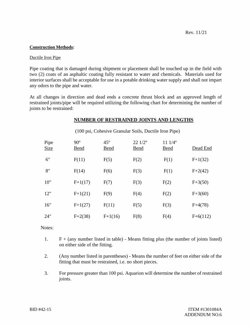
Pipe coating that is damaged during shipment or placement shall be touched up in the field with
two (2) coats of an asphaltic coating fully resistant to water and chemicals. Materials used for
interior surfaces shall be acceptable for use in a potable drinking water supply and shall not impart
any odors to the pipe and water.
At all changes in direction and dead ends a concrete thrust block and an approved length of
restrained joints/pipe will be required utilizing the following chart for determining the number of
joints to be restrained:
NUMBER OF RESTRAINED JOINTS AND LENGTHS
(100 psi, Cohesive Granular Soils, Ductile Iron Pipe)
Pipe 90º 45º 22 1/2º 11 1/4º
Size Bend Bend Bend Bend Dead End
6" F(11) F(5) F(2) F(1) F+1(32)
8" F(14) F(6) F(3) F(1) F+2(42)
10" F+1(17) F(7) F(3) F(2) F+3(50)
12" F+1(21) F(9) F(4) F(2) F+3(60)
16" F+1(27) F(11) F(5) F(3) F+4(78)
24" F+2(38) F+1(16) F(8) F(4) F+6(112)
Notes:
1. F + (any number listed in table) - Means fitting plus (the number of joints listed)
on either side of the fitting.
2. (Any number listed in parentheses) - Means the number of feet on either side of the
fitting that must be restrained, i.e. no short pieces.
3. For pressure greater than 100 psi. Aquarion will determine the number of restrained
joints.
Rev. 11/21
BID #42-15 ITEM #1301084A
ADDENDUM NO.6
Mechanical joint locking gaskets may be used to restrain pipe joints and shall be Field Lock 350,
Sure Stop 350, or approved equal and in accordance with ANSI/AWWA C111-12/A21.11
Standards, latest revision.
Installing Ductile Iron Pipe
All pipe installation shall conform to AWWA C600 Standards, latest revision, unless otherwise
modified by these specifications.
Ductile iron pipe shall be laid to a minimum depth of 4’-6” to the top of the pipe as shown on the
Typical Trench Detail, or as shown on the plans, unless otherwise directed by the Aquarion
Representative. Where the pipeline crosses existing utilities, a vertical clearance of twelve inches
(12") minimum shall be maintained, except for sanitary sewers where if the water main is within
ten (10) horizontal feet of the sewer, the water main must be at least eighteen inches (l8") above
the sewer. The pipe between bell holes shall bear continuously on approved material. If the
Contractor excavates below the required limit, the trench bottom shall be brought to the required
grade with an approved material as specified in these specifications at the Contractor's expense.
In laying pipe, the deflections given in AWWA Standard C600 latest revision shall not be
exceeded.
All pipe, valves and fittings shall be lowered carefully into the trench by means of mechanical
equipment in such a manner as to prevent them from being damaged. The insides of all bells and
outsides of spigots shall be wiped clean and dry and shall be free from oil or grease. During the
laying of the pipe, extra care shall be taken to see that no dirt, debris, tools, clothing, or other illicit
materials are allowed to be left in the pipe.
After the pipe is laid in the trench, the spigot end shall be centered in the bell and pushed into the
bell. Under no circumstances shall pipe be laid where there is water in the trench. The Contractor
shall install and joint the pipe in accordance with the manufacturer's instructions. The joints shall
be made continuous by the installation of metal wedges per the manufacturer’s instructions.
Aquarion will establish the location of the centerline of the pipeline. The Contractor shall establish
bench marks and offsets, as necessary, a suitable distance from the work to be done so that proper
lines and grades for the work may be maintained. The Contractor shall, to the best of their ability,
protect all survey points from damage.
The Contractor shall be responsible for placing the pipe accurately to the established lines and
grades as shown on the drawings or as directed by the Aquarion Representative.
When necessary to cut pipe in the field, the cutting shall be done such that neither the pipe nor the
lining shall be damaged and such that a smooth, right angle cut is made. A machine designed for
this purpose shall be used for the cutting.
It shall be the Contractor’s sole responsibility to procure and maintain a suitable storage area for
tools, materials, and equipment necessary to perform the work. The Contractor is responsible for

Rev. 11/21
BID #42-15 ITEM #1301084A
ADDENDUM NO.6
all costs associated with the storage of equipment and materials and shall not invoice these costs
to Aquarion or the Town. The storage area obtained by the Contractor shall not obstruct or
interfere with pedestrian or vehicle movement, and shall not occupy any space within the public
right-of-way, except with specific permission by Aquarion or the Town.
Materials shall be stored so as to ensure the preservation of their quality and fitness for the work.
When considered necessary, they shall be placed on wooden platforms and covered or stored in a
suitable building. The Contractor shall not use the storage area for bulk storage of hazardous
materials (e.g., gasoline, solvents, oil, etc.). Stored materials shall be located so as to facilitate
prompt inspection. The Contractor shall be present to unload piping and other materials delivered
to the jobsite prior to the Contractor’s planned mobilization to the project.
Installing HDPE Pipe
All HDPE pipe shall be handled according to the manufacturer’s specifications and
recommendations and industry standards. The insides of all pipes and outsides of all pipes at the
ends shall be wiped clean and dry and shall be free from oil or grease. During the laying of the
pipe, extra care shall be taken to see that no dirt, debris, tools, clothing, or other illicit materials
are allowed to be left in the pipe.
Under no circumstances shall pipe be laid where there is water in the trench. The Contractor shall
install and join the pipe in accordance with the manufacturer's specifications and recommendations
and industry standards. The pipe shall be made continuous by approved methods of butt fusion.
When necessary to cut pipe in the field, the cutting shall be done such that the pipe shall not be
damaged and such that a smooth, right angle to axis cut is made. A machine designed for this
purpose shall be used for the cutting. Demo, chop or gas powered saws are not permitted for
cutting HDPE pipe. No oil or lubricant shall be used on any saw because it can contaminate the
fusion surface and/or the fusion equipment.
The Contractor shall be responsible for placing the pipe accurately to the established lines and
grades as shown on the drawings or as directed by the Owner’s Representative.
Fusion
Sections of HDPE pipe should be joined into continuous lengths on the jobsite above ground. The
joining method shall be by butt fusion and shall be performed in strict accordance with the pipe
manufacturer’s specifications and recommendations and industry standards. The butt fusion
equipment used in the joining procedures should be capable of meeting all conditions
recommended by the pipe manufacturer. The butt fusion joining will produce a joint with weld
strength equal to or greater than the tensile strength of the pipe itself. All field welds shall be made
with fusion equipment equipped with a Data Logger. Temperature, fusion pressure and a graphic
representation of the fusion cycle shall be part of the quality control records. Butt fusion shall be
performed in accordance with ASTM F260 and the pipe manufacturer’s recommended procedures.
Rev. 11/21
BID #42-15 ITEM #1301084A
ADDENDUM NO.6
Before fusing an HDPE joint, the interior of all pipe and fittings shall be swabbed or sprayed with
a 1% hypochlorite solution in accordance with AWWA C651 Section 10. The same shall apply to
all tie ins of HDPE pipe to ductile iron pipe, as the pipe and the fittings for the tie in are not
typically disinfected with the rest of the newly installed main.
Fusion Technician
Each fusion technician shall be separately qualified to make each type of fusion joint. Fusion types
are butt fusion and electrofusion. Qualification for one type of fusion shall not qualify a technician
to make a different type of fusion joint.
Each fusion technician making butt fusion joints shall be qualified to make butt fusion joints in
accordance with ASTM F2620. Qualification shall be a documented demonstration of proficiency
by making joints in accordance with ASTM F2620 that are proved to be satisfactory by destructive
testing in accordance with ASTM F2620.
Excavation
The excavation defined herein shall be deemed earth excavation, which shall include the removal
of all material other than rock. The extent of trenching and excavation, including rock, shall be in
accordance with the Typical Trench Detail, and shall be 4” below the bottom of the pipe in earth
and 6” below the bottom of the pipe in rock. The depth of trench may be increased or decreased
at the discretion of the Aquarion Representative as required to avoid obstructions.
Hand excavation shall be employed whenever, in the opinion of the Aquarion Representative, it is
necessary to excavate around and/or expose existing utilities.
Excavated material, to the limits other than the limits defined for Removal of Unsuitable Material
that is deemed unsuitable material for use as bedding material or backfill above 12” above the top
of the pipe by the Aquarion Representative, shall be removed from the site and properly disposed
of.
Special care shall be taken to excavate accurately to grade. If the trench is over-excavated, it shall
be brought to grade, at the Contractor's expense, by refilling with approved material in compacted
layers, each layer not to exceed 6" in thickness if the depth is less than 12” or 12” in thickness if
the depth is greater than 12”.
Where the bottom of the trench, below the limit of excavation for placement of bedding material,
is found to be unstable or to contain material which, in the judgment of the Aquarion
Representative, should be removed, the Town’s Contractor shall excavate and remove such
material to the width and depth as shown on the Typical Trench Detail, as directed by the Aquarion
Representative. This excavated material shall be paid for as Excavation and Disposal of
Unsuitable Material (Water Main) (see Typical Trench Detail for vertical limit). Before the pipe
is installed, the subgrade shall be prepared by refilling with bedding material, in compacted layers,
each layer not to exceed 6” in thickness if the depth is less than 12” or 12” in thickness if the depth

Rev. 11/21
BID #42-15 ITEM #1301084A
ADDENDUM NO.6
is greater than 12”. The layers shall be thoroughly compacted so as to provide a uniform and
continuous bedding for the pipe. This material shall be paid for under Additional Backfill Material
(see Typical Trench Detail for vertical limit of Suitable Material).
Rock Excavation
Rock excavation and replacement with Additional Backfill Material, including bedding material,
is specified under other sections of these specifications.
Unauthorized Excavation
All unauthorized excavations outside the lines and grades shown and specified shall be at the
expense of the Contractor and the Contractor shall refill them with approved material, in a manner
as specified at his own expense. All backfill for unauthorized excavations shall be compacted in
12” lifts.
Storage and Disposal of Excavated Materials
Materials removed from the trenches shall be stored in such a manner that they will not interfere
unduly with pedestrian or vehicular traffic. Sufficient material suitable for backfill shall be stored
and hauled as necessary to replace excavated material that is unsuitable for backfill. Excess
excavated material shall be removed and legally disposed of away from the site by the Town’s
Contractor on the same day as the backfill has been placed.
Bedding Material
Bedding material shall be free from soft, thin, elongated, laminated, friable, micaceous, or
disintegrated pieces, mud, loam, organic matter, wood, clay, or other deleterious material, and
frozen material.
Bedding material shall be used for backfilling trenches under, along and over the pipe to a level of
12" above the top of the pipe, as shown on the drawings or as directed by the Aquarion
Representative, and shall be bank run gravel, ¾” crushed stone, processed aggregate base, or native
material.
The Contractor must properly bed the pipe with bedding material and shall take care in doing so.
The Contractor shall place bank run gravel, ¾” crushed stone, processed aggregate base, or native
material under, along and over the pipe as bedding material to the minimum depth as shown on
the Typical Trench Detail or as directed by the Aquarion Representative. Native material is
acceptable as bedding material as long as it meets the requirements of these specifications. The
bedding material shall be spread in layers and shall be compacted in place at the proper grade to
provide a solid uniform bed for the pipe or structure for the full width and length of the bottom of
the excavation. Bell holes shall be carefully dug at the ends of the pipe to provide ample room for
properly making and checking of joints and providing room for the minimum depth of compacted
bedding material under the bell.
Rev. 11/21
BID #42-15 ITEM #1301084A
ADDENDUM NO.6
When the pipe has been bedded satisfactorily and the joint completed, the recess under the bell
shall be refilled and tamped on each side of the pipe to hold it securely in place, care being taken
not to disturb the position of the pipe during the process, and in such a manner that the bearing is
distributed evenly over the entire length of the pipe.
Any material used for Bedding Material shall not have stones larger than 4”. No stones shall be
in contact with the pipe or be within 4” of the pipe.
Backfilling
Unless otherwise specified or directed, all trenches and excavations shall be backfilled
immediately after installation and inspection of the pipe.
The Contractor shall use suitable material from excess excavation from other portions of the work
or from approved gravel pits. It shall be carefully deposited in uniform layers not exceeding twelve
inches (12") in depth, and unless otherwise permitted, each layer shall be carefully and solidly
tamped and compacted with appropriate tools in 12” lifts in such a manner as to avoid disturbing
the completed work.
Backfill for the excavation (above the limits of the bedding material) shall be with approved
Additional Backfill Material, as specified under Item #1300151A of these specifications, free from
organic matter. No stones larger than 12” shall be used in the trench as backfill from 12” above
the top of the pipe to the surface. In depositing stones up to 12”, care must be taken not to damage
the pipe or any structure. Stones which are used in backfilling shall be so distributed through the
mass that all interstices are filled with fine material. Backfill shall be deposited in layers not
exceeding 12” in depth and compacted.
Rock and other excavated materials from trenches and excavations may be used as backfill,
provided individual pieces of rock are not larger than 12” and that they are placed so that voids are
filled with the backfill material. No rock or other excavated materials from trenches and
excavations shall be placed within 12” from the top of the pipe.
Backfilling within 2' of structures shall be uniformly deposited on all sides and, unless otherwise
permitted, solidly compacted in such manner as to avoid damaging the structure or producing
unequal pressures thereon.
When sheeting is drawn, all cavities remaining in or adjoining the trench shall be solidly backfilled
and compacted. When sheeting is permitted to be left in place, all cavities behind such sheeting
shall be solidly backfilled and compacted.
If the material from the trench excavation is considered, in the opinion of the Aquarion
Representative, to be unsuitable for use as backfill, the Aquarion Representative shall order the
Contractor to furnish suitable Additional Backfill Material for backfill to the limits shown on the
Typical Trench Detail. The removal and disposal of this material, if not suitable for backfill, down
Rev. 11/21
BID #42-15 ITEM #1301084A
ADDENDUM NO.6
to the lower vertical limit of the bedding material is included in the linear foot price of the pipe
installation. See the Typical Trench Detail for the vertical limits of Additional Backfill Material
and bedding material.
Trench Bracing, Sheeting and Trench Boxes
Where trench conditions are found to consist of material which is unstable to such a degree that it
cannot be removed and replaced with an approved material without creating an occupational
hazard, the Contractor shall utilize trench bracing, sheeting or trench boxes to support the trench.
The Contractor must conform to all applicable State and OSHA standards for trench conditions.
The sides of the trenches and excavations shall be supported by adequate trench bracing, sheeting,
or trench boxes. The Contractor shall be held accountable and responsible for the amount of all
trench bracing, sheeting, and trench boxes used and for all damages to persons or property resulting
from the improper quality, strength, placing, maintaining, or removing of the trench bracing,
sheeting, or trench boxes. When trench bracing, sheeting, or trench boxes are removed, care shall
be taken not to disturb the newly installed pipe, appurtenances, or existing utilities and structures.
Trench bracing is defined as planks placed against opposite sides of the excavation and is held in
place by timber struts or some extendable brace.
Sheeting is defined as continuous sheet piling of either steel or wood with whalers or shoring. No
sheeting is to be left in place unless expressly permitted by the Aquarion Representative.
All materials necessary for trench bracing, sheeting, or trench boxes shall be provided by the
Contractor and included in this section.
All construction methods necessary to install and maintain trench bracing, sheeting, or trench
boxes shall conform to OSHA Standards.
Dewatering
The Contractor shall provide all necessary pumps, drains, well point systems, and other means for
removing water from the trenches and from other parts of the work. Before pipes are laid or
structures built, the trenches and excavations shall be free from water and, if necessary, suitable
drainage facilities shall be provided and maintained. Any drainage system used by the Contractor
shall be subject to the approval of the Aquarion Representative. Subgrade damaged by failure to
properly dewater will be repaired and replaced at the Contractor's expense.
Water from the trenches and excavations shall be disposed of in such a manner as will neither
cause injury to public health nor to public or private property, nor to the work completed or in
progress.

Rev. 11/21
BID #42-15 ITEM #1301084A
ADDENDUM NO.6
Thrust Blocks
Concrete for thrust blocks shall be Class “C” Concrete (Water Main). Thrust blocks shall be in
accordance with these specifications and the Aquarion Standard Details. Thrust blocks are
required at all tees, bends and dead ends.
Warning Tape
In accordance with "Call Before You Dig" (CBYD) regulations, all underground utilities must be
identified with warning tape during the pipe installation. The Contractor shall provide a suitable
continuous length of warning tape located above the pipe, as shown on the Typical Trench Detail.
The minimum separation between the facility and warning tape shall be 2’. The warning tape shall
be 3” wide (minimum), 4.0 MIL polyethylene film, blue in color in accordance with the APWA
National Color Code, durable, designed to withstand extended underground exposure, and marked
with the words "Water Main" durably imprinted in accordance with acceptable standards. Warning
tape will be supplied by the Contractor. Warning tape should be installed on all excavations
regardless of the length of the water main being exposed.
Safety Procedures for Storing Pipe
Pipe shall always be blocked to prevent it from rolling or falling.
Threaded pipe shall be handled with care, because threads are sharp and can easily cause injury.
Pipes larger than 2 inches in diameter shall be stacked in storage with spacing strips between
each row.
Each row of stacked pipe shall be arranged and blocked to prevent its rolling from the pile. All
blocking should be of reasonably permanent material, such as chemically-treated wood.
Pipe will always be withdrawn from the top row.
In pipe storage areas where pipe material is handled by a crane, workers shall be conversant
with the signals used by operators and be careful to stay clear of the load's path. Standard
signals shall be used.
Storage area shall be maintained in a safe condition at all times. Repairs to the storage area
shall be made whenever necessary.
The Contractor will conform to all applicable State and OSHA standards for pipe line safety.
AWWA-M3, "Safety Practice for Water Utilities" will be enforced.
During the progress of the work, all roads shall be kept open for the passage of traffic and
pedestrians and shall not be unnecessarily obstructed unless authorized by the authority having
jurisdiction over same. Driveways, sidewalks and crossings shall be closed as short a time as
possible while pipe is being placed, and passage shall be restored as soon as possible thereafter by
properly placed backfill or approved bridging. The Contractor shall take such measures at their
own expense as may be necessary to keep the roads open for traffic, and shall give advance notice
to the Engineer, town public works department, local police and state police as required.
Rev. 11/21
BID #42-15 ITEM #1301084A
ADDENDUM NO.6
Warning signs shall be provided along all roads where work is in progress. The Contractor shall
notify and make all arrangements with the Connecticut Department of Transportation, town public
works department, local police and state police for direction of traffic past the equipment,
machinery, or construction operations. Barricades and lights shall be provided to protect traffic.
Where trenches have been cut in road shoulders on which traffic may pass at times, warning signs
shall be placed at frequent intervals and maintained until the shoulder is safe for travel. All such
work and operations shall be in accordance with the requirements of the Connecticut Department
of Transportation, public works department, local police and state police.
Should the Contractor or their employees neglect to set out and maintain barricades or lights, as
required in these specifications, Aquarion may immediately and without notice, arrange for
furnishing, installing and maintaining barricades or lights, and any other precaution deemed
necessary. The cost thereof shall be borne by the Contractor and may be deducted from any
amount due or to become due to the Contractor under these specifications.
The Contractor shall be held responsible for any damages that may have to be paid as a
consequence of the Contractor's failure to protect the public.
The Contractor must follow the Maintenance and Protection of Traffic specification in this
Contract.
Before starting any work, the Contractor shall arrange with the municipal or state officials having
jurisdiction for the use of routes of travel for hauling materials, including surplus earth and rock
that will result in minimum inconvenience to the traveling public. Routes of travel so scheduled
shall be adhered to throughout the course of the work, unless otherwise approved.
The Contractor shall take all necessary precautions to prevent and abate nuisance caused by dust
arising from his operations. Approved methods applicable to various parts of the work such as
application of water spray or calcium chloride shall be used. This also applies to maintaining
temporary paving nuisance free until permanent paving is placed.
The Contractor shall provide, erect and maintain all necessary barricades, danger signals and signs,
provide a sufficient number of watchmen and take all necessary precautions for the protection for
the work and workmen and for the safety of the public.
Handling and Distribution of Pipe, Valves and Fittings
Pipe shall be handled and supported with woven fiber pipe slings, or approved equals. Hooks,
chains, wire rope, or any other device that may cause damage to the pipe during handling and
support shall not be used. Care shall be taken when handling the pipe so as not to cut, gouge, or
scratch the pipe in any way.
The pipe, valves and fittings shall be handled and protected during loading, transporting, and
unloading operations in such manner as to avoid damage. Pipe, specials, and valves shall be
Rev. 11/21
BID #42-15 ITEM #1301084A
ADDENDUM NO.6
unloaded by lifting with hoists or skidding so as to avoid shock or damage. Under no
circumstances shall they be dropped nor shall they be permitted to roll against pipe already on the
ground. Insofar as practicable, each piece of pipe shall be delivered and unloaded near the place
where it is to be installed and where it will not interfere with excavation operations, traffic, or
adjacent property owners and may be readily inspected by the Aquarion Representative. If this is
not possible, the pipe, valves and fittings shall be stored in a safe area as close to the job site as
possible. The Contractor is responsible for identifying a location (staging area) for storage of pipe,
valves, fittings, excavated material and borrow material. The Contractor is responsible for
delivering all materials to said location. The Contractor is responsible for stringing pipe along the
intended pipeline route. All damaged pipe, valves and fittings will be rejected by the Aquarion
Representative and such rejected pipe, valves and fittings shall be removed from the site by the
Contractor. In the event of slight damage to the coating or lining, Aquarion may permit the damage
to be repaired at the site. Such repairs shall be made at the Contractor's expense. Once the
Contractor receives shipment of pipe, valves and fittings, the Contractor shall be responsible for
replacing any materials that may be stolen from the Contractor’s storage area.
Cleaning and Inspection of Pipe, Valves and Fittings
The insides of the pipes, valves and fittings shall be thoroughly cleaned before laying and shall be
kept clean until accepted in the completed work. Whenever the work is interrupted, all open ends
of pipe shall be temporarily closed by watertight plugs. No trench water shall be permitted to enter
the pipe. All pipe and special castings shall be carefully examined for defects and no pipe or
special casting shall be laid which is known to be defective. If any such pipe or casting is
discovered to be defective after placement, it shall be removed and replaced with a sound pipe or
casting by the Contractor at his own expense.
Clearing and Grubbing
The Contractor shall remove all trees, brush, shrubs, and debris where encountered in the line of
work only to the extent necessary for the prosecution of the water main relocation work.
Unless otherwise specified, all brush and trees shall be cut within six inches (6") of the ground.
Cutting and removal of cleared materials shall be carried out in such manner as to avoid injury to
other trees and structures.
Burning will not be permitted on the site.
Trees, stumps, brush, and debris shall be disposed of away from the site by the Contractor at no
additional cost to Aquarion or the Town.
Clean-Up
During progress of the work, the Contractor shall keep the construction areas in a neat condition,
free from accumulations of waste material and rubbish.
Rev. 11/21
BID #42-15 ITEM #1301084A
ADDENDUM NO.6
On or before completion of the work and before acceptance and final payment shall be made, the
Contractor shall clean and remove from the site and adjacent property, all surplus and discarded
materials, rubbish and temporary structures, restore in an acceptable manner all property and leave
the whole in a neat and presentable condition.
Periodically, as the work progresses and immediately after the work has been completed, the
Contractor shall remove all excess materials from the area of the work. The area, in general, shall
be kept clean and orderly and returned to a neat condition. The area of construction along
roadways shall be swept with a broom, either by hand or mechanically, each day after completion
of the day's work.
Trees, stumps, brush, and debris shall be disposed of by the Contractor off the site. Burning will
not be permitted.
Method of Measurement:
Work under this section will be measured for payment per linear foot of ductile iron or HDPE pipe
installed, of the size required, complete in place, backfilled, tested and accepted.
The following will not be measured separately for payment, but shall be included in the linear foot
cost of the pipe installation:
saw-cutting of existing pavement
removal of asphalt and concrete pavement up to and including 6” in depth
excavating to the depth necessary to install the pipe and bedding material
stockpiling and storing of the excavated material if suitable for backfill
removal and disposal of the excavated material if deemed unsuitable for backfill
furnishing and installing bedding material up to 12” above the top of the pipe
backfilling with native material if suitable for backfill
compacting in 12” lifts
installation of bends, valves, reducers, sleeves, couplings and tees
mechanical joint restraints, hardware, bolts, nuts, glands, and gaskets
cutting, cleaning and fusing of HDPE pipe joints
thrust block excavation, forming and installation excluding concrete and reinforcing steel,
which will be measured for payment under Item #1304111A
warning tape
trench bracing, sheeting and trench boxes
dewatering
Excavation and Disposal of Unsuitable Material
Hydrants and services, if included in this project, shall be measured separately for payment under
those appropriate Items.
Rev. 11/21
BID #42-15 ITEM #1301084A
ADDENDUM NO.6
Bedding material furnished, installed, and compacted, to the bedding material limits shown on the
Typical Trench Detail, will not be measured separately for payment, but shall be included in the
linear foot cost of the pipe installation.
Rock In Trench, Class “C” Concrete (Water Main), Additional Backfill Material, and Temporary
and Permanent Pavement shall be measured separately for payment under those appropriate Items.
Repairs, due to errors in installation, completed by the Contractor in order to pass the Hydrostatic
Test will not be measured separately for payment.
Basis of Payment:
Work under this section will be paid for at the contract unit price bid per linear foot for “12”
Ductile Iron Pipe (Water Main)” installed complete in place, backfilled with suitable material,
tested and accepted.
Hydrants, services and air relief valves, if included in this project, will be paid for separately as
indicated elsewhere in these special provisions.
No separate payment will be made for installing bends, valves, reducers, sleeves, couplings, tees,
plugs, mechanical joint restraints, hardware, cutting, cleaning or fusing of HDPE joints or thrust
block installation, but the installation of these items shall be included in the linear foot cost of the
pipe installation.
No separate payment will be made for bedding material furnished, installed, and compacted, to the
bedding material limits shown on the Typical Trench Detail, but shall be included in the linear foot
cost of the pipe installation. No separate payment will be made for Excavation and Disposal of Unsuitable Material, but shall be
included in the linear foot cost of the pipe installation.
Rock In Trench, Class “C” Concrete (Water Main), Additional Backfill Material, and Temporary
Pavement Repair and Permanent Pavement Replacement will be paid for separately at the contract
unit price under those appropriate Items.
No separate payment will be made for repairs, due to errors in installation, completed by the
Contractor in order to pass the Hydrostatic Test.
Pay Item Pay Unit
12” Ductile Iron Pipe (Water Main) LF
BID #42-15 ITEM #1301862A
ADDENDUM NO.6
ITEM #1301862A – FURNISH PIPE, VALVES AND MISCELLANEOUS
FITTINGS (WATER MAIN)
Description: A. Work under this Section covers the acquisition and furnishing of all materials, equipment,
appurtenances and incidentals required as shown on the Aquarion Relocation Plans and
specified herein, including ductile iron and/or HDPE pipe, valves, tees, sleeves, fittings,
bends, plugs, joint restraints, casing pipe and appurtenances of the various types specified
in accordance with the drawings, specifications and as directed by the Engineer.
Installation of the materials acquired under this special provision is not included in this
work, but is paid for under Item #1301084A – 12” Ductile Iron Pipe (Water Main).
B. Work and materials covered under this Section of the specifications shall be in
strict compliance with Aquarion Water Company Standards. All water main materials
shall conform to the Aquarion Water Company’s “List of Approved Materials” dated
December 2020, which is attached to this specification.
E. Interruption of and connection to the existing water main system, at the locations
indicated on the Relocation Plans, shall be in strict accordance with the Aquarion Water
Company's requirements and shall only occur with the prior approval of the Aquarion
Water Company.
F. Under no circumstance shall the completed water main construction be placed into active
service until final inspection by and written approval has been obtained from Aquarion.
G. All standards, codes, specifications, etc., referred to herein shall be the latest issue.
H. It is not intended that the Relocation Plans and Details shall show every pipe, fitting,
valve, special or appurtenance but the State’s Contractor shall acquire all material
necessary to complete the Work in accordance with the best practice and the intent of the
Relocation Plans, Details and these Special Provisions.
I. REFERENCES
1. All materials shall conform to the requirements of the Aquarion Water Company’s “List
of Approved Materials” (attached).
2. The publications listed below form a part of this specification to the extent referenced.
The following publications are referred to in the text by the basic designation only:
AMERICAN NATIONAL STANDARDS INSTITUTE, INC. (ANSI)

BID #42-15 ITEM #1301862A
ADDENDUM NO.6
ANSI A21.4 Cement Mortar Lining for Ductile Iron Pipe and Fittings for Water
ANSI A21.11 Rubber Gasket Joints for Ductile-Iron and Gray-Iron Pressure
Pipe and Fittings
ANSI A21.51 Ductile-Iron Pipe, Centrifugally Cast in Metal Molds or Sand- Lined
Moles, for Water or Other Liquids
ANSI B18.2.2 Square and Hex Nuts
ANSI B18.5 Round Head Bolts
AMERICAN SOCIETY FOR TESTING AND MATERIALS (ASTM)
ASTM A-48 Gray Iron Castings
ASTM A-536 Ductile Iron Castings
ASTM A-563 Carbon and Alloy Steel Nuts
AMERICAN WATER WORKS ASSOCIATION (AWWA)
AWWA C-104 Cement-Mortar Lining for Ductile-Iron Pipe and Fittings for Water
AWWA C-110 Ductile-Iron and Gray-Iron Fittings, 3 inch through 48 inch for Water
and Other Liquids
AWWA C-111 Rubber Gasket Joints for Ductile-Iron and Gray-Iron Pressure Pipe and
Fittings
AWWA C-151 Ductile-Iron Pipe, Centrifugally Cast in Metal Molds or Sand-lined
Molds, for Water or Other Liquids
AWWA C-153 Ductile-Iron Compact Fittings, (3 inch through 12 inch), for Water and
Other Liquids
AWWA C-600 Installation of Ductile Iron Water Mains and Appurtenances
J. QUALITY ASSURANCE
1. The Contractor shall furnish the Engineer any Certified Test Report and Materials
Certificate required by the Contract or the Engineer. This shall include
manufacturer’s notarized test reports and methods of test to show compliance with
all specification requirements, and notarized certificates of conformance stating that
all materials to be furnished under this Specification conform to all specification
requirements, and each shipment of pipe, fittings, joints and gaskets and accessories
meet all requirements of the Specifications.
2. The Contractor shall furnish to the Aquarion Water Company manufacturer's written
transcripts in accordance with Section 51-14 of AWWA Standard C151, latest
revision.
3. Qualifications of the Installer: Only thoroughly trained and experienced personnel
who are completely familiar with the requirements for this work shall be involved
with the work. Personnel must be capable of carrying out the recommendations of
the manufacturer of the piping, valves, fittings and appurtenances for the proper
BID #42-15 ITEM #1301862A
ADDENDUM NO.6
installation procedures.
4. Comply with State and local controlling authority requirements for materials,
installation, fire protection, testing, disinfection and connection to existing water
mains.
5. Comply with NFPA 24 for fire-protection water main piping materials and
installation. K. SUBMITTALS
1. Submittals shall be made for the following items in accordance with the provisions of
these Specifications and shall include the following:
a. Manufacturer's Catalog Data and Standard Drawings for Pipe and Fittings.
b. Manufacturer's Catalog Data and Standard Drawings for Joints and Couplings.
c. Manufacturer's Catalog Data and Standard Drawings for Mechanical Sleeves and
Seals
d. Certificates of Compliance for pipe and fittings.
f. Certificates of Compliance for shop-applied linings and coatings.
g. Certificates of Compliance for pipe joint materials.
h. Certificates shall attest that tests set forth in each applicable referenced publication
have been performed, whether specified in that publication to be mandatory or
otherwise and that production control tests have been performed at the intervals or
frequency specified in the publication. Other tests shall have been performed
within three (3) years of the date of submittal of certificates on the same type, class,
grade, and size of material as is being provided for the project.
i. All permanently incorporated steel and iron used in the construction of the Project
must have been produced and fabricated in the United States.
j. Contractor shall have its pipe supplier prepare and shall submit to the Aquarion
Water Company a "LAYING SCHEDULE" of all pipe and accessories to be
furnished and installed under this Contract. No work shall be undertaken until the
laying schedule has been submitted to and approved by the Aquarion Water
Company.
BID #42-15 ITEM #1301862A
ADDENDUM NO.6
L. DELIVERY, STORAGE AND HANDLING
1. Inspect materials delivered to site for damage. Unload and store with minimum
handling. Store materials on site in enclosures or under protective covering. Store
jointing materials and rubber gaskets under cover out of direct sunlight. Do not store
materials directly on the ground. Keep inside of pipes and fittings free of dirt and
debris.
2. Handle pipe, fittings, and other accessories in a manner to ensure delivery to the site
in sound undamaged condition. Take special care to avoid injury to coatings and
linings on pipe and fittings and make satisfactory repairs if coatings or linings are
damaged. Carry, do not drag, pipe. Store jointing materials and rubber gaskets that
are not to be installed promptly, under cover out of direct sunlight.
M. PROJECT CONDITIONS
1. Perform site survey research public utility records, and verify existing utility
locations. Contact utility-locating service in the project area.
2. Verify that water main piping may be installed in conformance with the Aquarion
Relocation Plans, details and Special Conditions.
3. It is not intended that the drawings shall show every pipe, fitting, valve, etc., but the
Contractor shall be required to furnish, without additional charge, all material
necessary to complete the work in accordance with the best practice and intent of
drawings and specifications.
4. All necessary operations of valves required for the work of this contract will be
conducted by the Aquarion Water Company. The Contractor shall be responsible
for notifying the Aquarion Water Company a minimum of 2 weeks in advance of
any desired valve operations.
N. SEQUENCING AND SCHEDULING
1. Coordinate connection to existing water main with the Aquarion Water Company.
2. Coordinate with other utility work.
3. Coordinate with the construction staging plans for this project.
Materials:
A. All materials and workmanship, whether or not specifically described or shown, or
whether implied, shall be only first quality new and of a grade satisfactory to the Aquarion
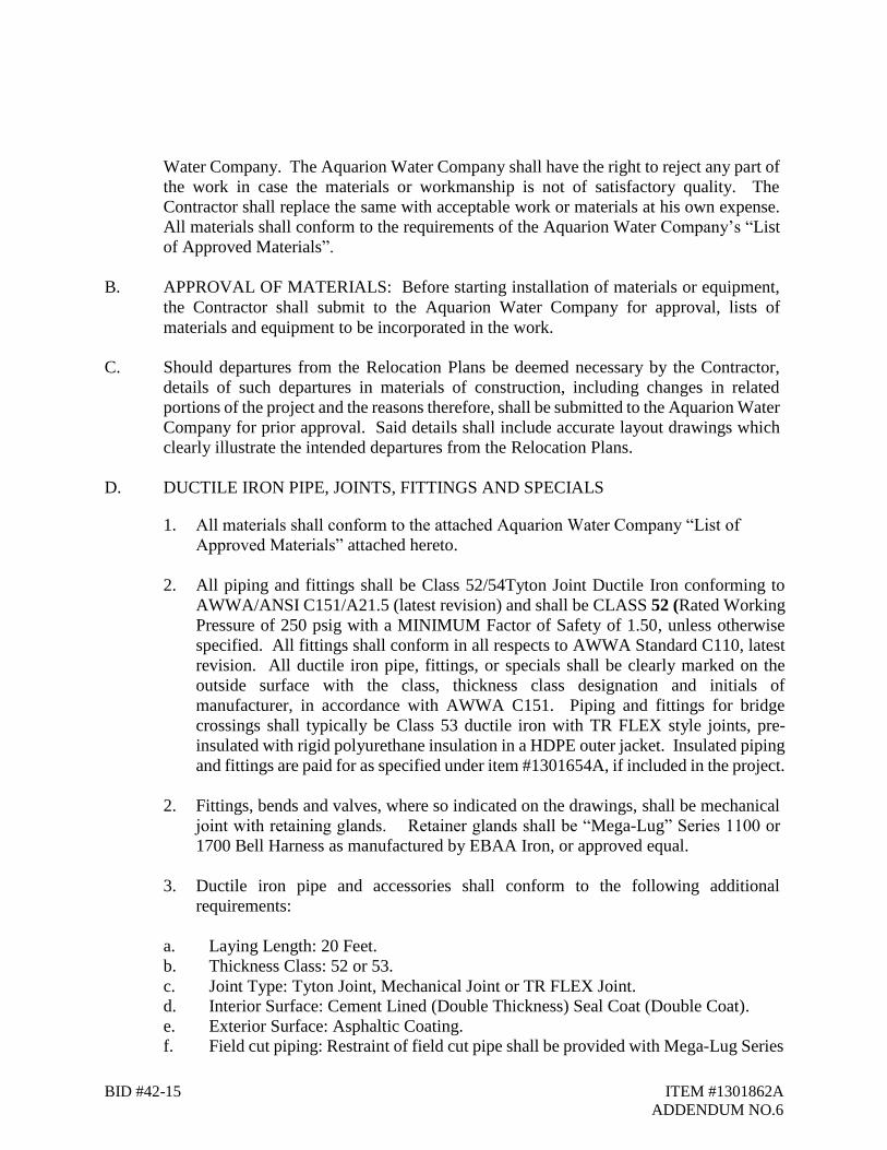
BID #42-15 ITEM #1301862A
ADDENDUM NO.6
Water Company. The Aquarion Water Company shall have the right to reject any part of
the work in case the materials or workmanship is not of satisfactory quality. The
Contractor shall replace the same with acceptable work or materials at his own expense.
All materials shall conform to the requirements of the Aquarion Water Company’s “List
of Approved Materials”.
B. APPROVAL OF MATERIALS: Before starting installation of materials or equipment,
the Contractor shall submit to the Aquarion Water Company for approval, lists of
materials and equipment to be incorporated in the work.
C. Should departures from the Relocation Plans be deemed necessary by the Contractor,
details of such departures in materials of construction, including changes in related
portions of the project and the reasons therefore, shall be submitted to the Aquarion Water
Company for prior approval. Said details shall include accurate layout drawings which
clearly illustrate the intended departures from the Relocation Plans.
D. DUCTILE IRON PIPE, JOINTS, FITTINGS AND SPECIALS
1. All materials shall conform to the attached Aquarion Water Company “List of
Approved Materials” attached hereto.
2. All piping and fittings shall be Class 52/54Tyton Joint Ductile Iron conforming to
AWWA/ANSI C151/A21.5 (latest revision) and shall be CLASS 52 (Rated Working
Pressure of 250 psig with a MINIMUM Factor of Safety of 1.50, unless otherwise
specified. All fittings shall conform in all respects to AWWA Standard C110, latest
revision. All ductile iron pipe, fittings, or specials shall be clearly marked on the
outside surface with the class, thickness class designation and initials of
manufacturer, in accordance with AWWA C151. Piping and fittings for bridge
crossings shall typically be Class 53 ductile iron with TR FLEX style joints, pre-
insulated with rigid polyurethane insulation in a HDPE outer jacket. Insulated piping
and fittings are paid for as specified under item #1301654A, if included in the project.
2. Fittings, bends and valves, where so indicated on the drawings, shall be mechanical
joint with retaining glands. Retainer glands shall be “Mega-Lug” Series 1100 or
1700 Bell Harness as manufactured by EBAA Iron, or approved equal.
3. Ductile iron pipe and accessories shall conform to the following additional
requirements:
a. Laying Length: 20 Feet.
b. Thickness Class: 52 or 53.
c. Joint Type: Tyton Joint, Mechanical Joint or TR FLEX Joint.
d. Interior Surface: Cement Lined (Double Thickness) Seal Coat (Double Coat).
e. Exterior Surface: Asphaltic Coating.
f. Field cut piping: Restraint of field cut pipe shall be provided with Mega-Lug Series

BID #42-15 ITEM #1301862A
ADDENDUM NO.6
1700 Bell Harness as manufactured by EBAA Iron, or approved equal. Fittings for water mains shall conform in all respects to AWWA Standard C110, latest revision, and to the additional requirements specified herein.
4. Fittings and accessories shall conform to the following additional requirements specified
herein:
a. Joint Type: Mechanical with retaining glands and split retaining glands.
Retainer glands shall be “Mega lug” Series 1100 as manufactured by EBAA Iron,
or approved equal. Locking Tyton type push on gaskets shall be Field Lok as
manufactured by U.S. Pipe, or approved equal, where shown on the drawings and
as directed by the Engineer.
b. Pressure Rating: 350 psi c. Type of Iron: Ductile
d. Interior Surface: Cement Lined (Double Thickness) Seal Coat (Double Coat)
e. Exterior Surface: Asphaltic Coating
5. Cement mortar lining for pipe and fittings, as specified above shall conform in all respects
to AWWA Standard C104 (latest revision). Lining thickness shall be twice that specified
in Section 4.7.1 of AWWA Standard C104. Seal coat shall be twice that specified in
Section 4.11 of AWWA Standard C104.
6 Rubber gasket joints for the water main pipe and fittings, as specified above, shall
conform to AWWA Standard C111/A21.11 Standard for Rubber Gasket Joints for
Ductile Iron Pressure Pipe and Fittings (latest revision).
7. Pipe couplings and sleeves shall be installed where required for connection to existing
work and as shown on the Drawings. Pipe couplings shall be solid sleeves giving a
watertight seal suitable for water pressure to 250 psi. As approved by the Engineer
8. All pipe, pipe fittings, accessories and appurtenances shall be new and unused.
9. All bolts, nuts, rods, and miscellaneous connecting pieces not provided with an approved
factory coating shall be given two (2) coats of bit mastic coal-tar after installation.
10. Corporation and curb stops shall be as specified in the attached “List of Approved
Materials”, “Ball Type”. Corporation thread is to be CC (for DIP) and shall be in
conformance with AWWA Standard C-800, latest edition. The corporation stop inlet
shall have a standard AWWA corporation valve inlet thread and the outlet shall be
a compression connection for copper tubing. Curb stops shall have a compression
connection for copper tubing at both ends.
12. Copper pipe shall be of soft seamless copper tubes with no soldered joints underground,
suitable for use as underground water service connections conforming to ASTM
specification B-88-47, “Type K”.
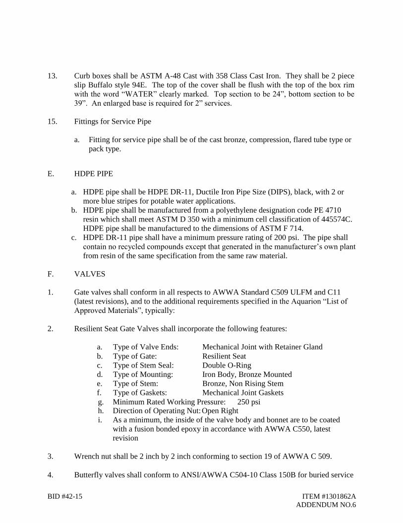
BID #42-15 ITEM #1301862A
ADDENDUM NO.6
13. Curb boxes shall be ASTM A-48 Cast with 358 Class Cast Iron. They shall be 2 piece
slip Buffalo style 94E. The top of the cover shall be flush with the top of the box rim
with the word “WATER” clearly marked. Top section to be 24”, bottom section to be
39”. An enlarged base is required for 2” services.
15. Fittings for Service Pipe
a. Fitting for service pipe shall be of the cast bronze, compression, flared tube type or
pack type.
E. HDPE PIPE
a. HDPE pipe shall be HDPE DR-11, Ductile Iron Pipe Size (DIPS), black, with 2 or
more blue stripes for potable water applications.
b. HDPE pipe shall be manufactured from a polyethylene designation code PE 4710
resin which shall meet ASTM D 350 with a minimum cell classification of 445574C.
HDPE pipe shall be manufactured to the dimensions of ASTM F 714.
c. HDPE DR-11 pipe shall have a minimum pressure rating of 200 psi. The pipe shall
contain no recycled compounds except that generated in the manufacturer’s own plant
from resin of the same specification from the same raw material.
F. VALVES
1. Gate valves shall conform in all respects to AWWA Standard C509 ULFM and C11
(latest revisions), and to the additional requirements specified in the Aquarion “List of
Approved Materials”, typically:
2. Resilient Seat Gate Valves shall incorporate the following features:
a. Type of Valve Ends: Mechanical Joint with Retainer Gland
b. Type of Gate: Resilient Seat
c. Type of Stem Seal: Double O-Ring
d. Type of Mounting: Iron Body, Bronze Mounted
e. Type of Stem: Bronze, Non Rising Stem
f. Type of Gaskets: Mechanical Joint Gaskets
g. Minimum Rated Working Pressure: 250 psi h. Direction of Operating Nut: Open Right
i. As a minimum, the inside of the valve body and bonnet are to be coated
with a fusion bonded epoxy in accordance with AWWA C550, latest
revision
3. Wrench nut shall be 2 inch by 2 inch conforming to section 19 of AWWA C 509.
4. Butterfly valves shall conform to ANSI/AWWA C504-10 Class 150B for buried service

BID #42-15 ITEM #1301862A
ADDENDUM NO.6
only. Specific requirements shall be in accordance with the attached Aquarion “List of Approved Materials”.
5. Valve Box
a. Valve boxes shall be ASTM A-48 Cast with 358 Class cast iron, two piece, slip type,
with a 26” top section with bottom flange and 36” bottom section.
b. Covers shall be cast iron, marked "WATER", with two notched openings.
c. Valve boxes and covers shall be United States made only.
d. Valve boxes shall be centered over the operating nut of the valve and set to be flush
at final pavement or finished grade.
e. Valve boxes shall be of good quality cast iron free from all defects in material and
workmanship and shall be coated with coal-tar pitch enamel or other approved
coating.
G. APPROVED MANUFACTURERS
1. Refer to the Aquarion Water Company “List of Approved Materials”, unless
otherwise noted below.
2. Bolt Through MJ Adapter For Joint Restraint
a. Infact Corporation Foster Adapter 6-12 inches for the direct connection of
MJ fittings, or approved equal.
3. Where there is a specific conflict between this specification and Aquarion
Water Company’s “List of Approved Materials”, the List of Approved
Materials shall apply.
Construction Methods:
A. INSTALLATION OF PIPE - GENERAL REQUIREMENTS
1. Refer to Item #1301084A – 12” Ductile Iron Pipe (Water Main).
B. INSTALLATION - PIPE, FITTINGS AND ACCESSORIES
1. Refer to Item #1301084A – 12” Ductile Iron Pipe (Water Main).
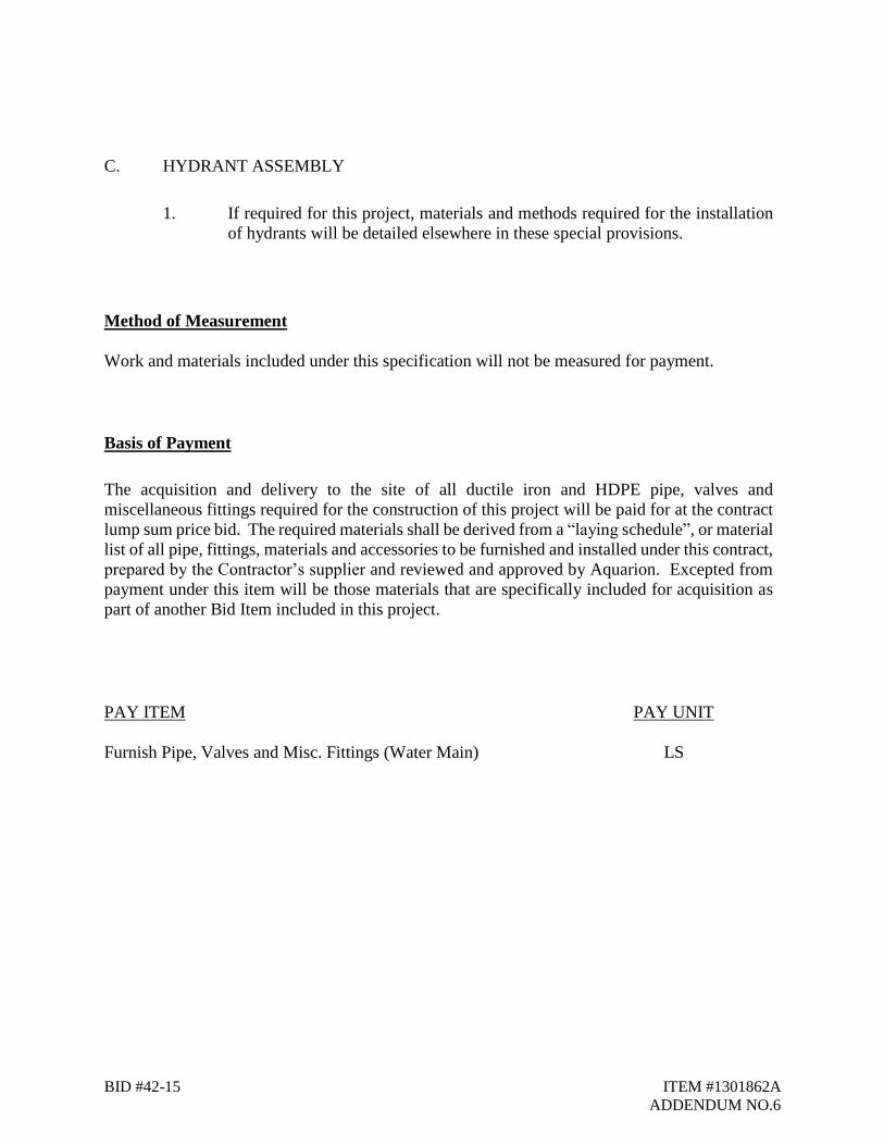
BID #42-15 ITEM #1301862A
ADDENDUM NO.6
C. HYDRANT ASSEMBLY
1. If required for this project, materials and methods required for the installation
of hydrants will be detailed elsewhere in these special provisions.
Method of Measurement
Work and materials included under this specification will not be measured for payment.
Basis of Payment
The acquisition and delivery to the site of all ductile iron and HDPE pipe, valves and
miscellaneous fittings required for the construction of this project will be paid for at the contract
lump sum price bid. The required materials shall be derived from a “laying schedule”, or material
list of all pipe, fittings, materials and accessories to be furnished and installed under this contract,
prepared by the Contractor’s supplier and reviewed and approved by Aquarion. Excepted from
payment under this item will be those materials that are specifically included for acquisition as
part of another Bid Item included in this project.
PAY ITEM PAY UNIT
Furnish Pipe, Valves and Misc. Fittings (Water Main) LS
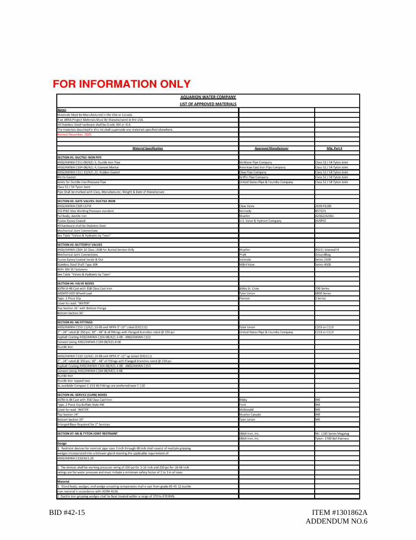
BID #42-15 ITEM #1301862A
ADDENDUM NO.6
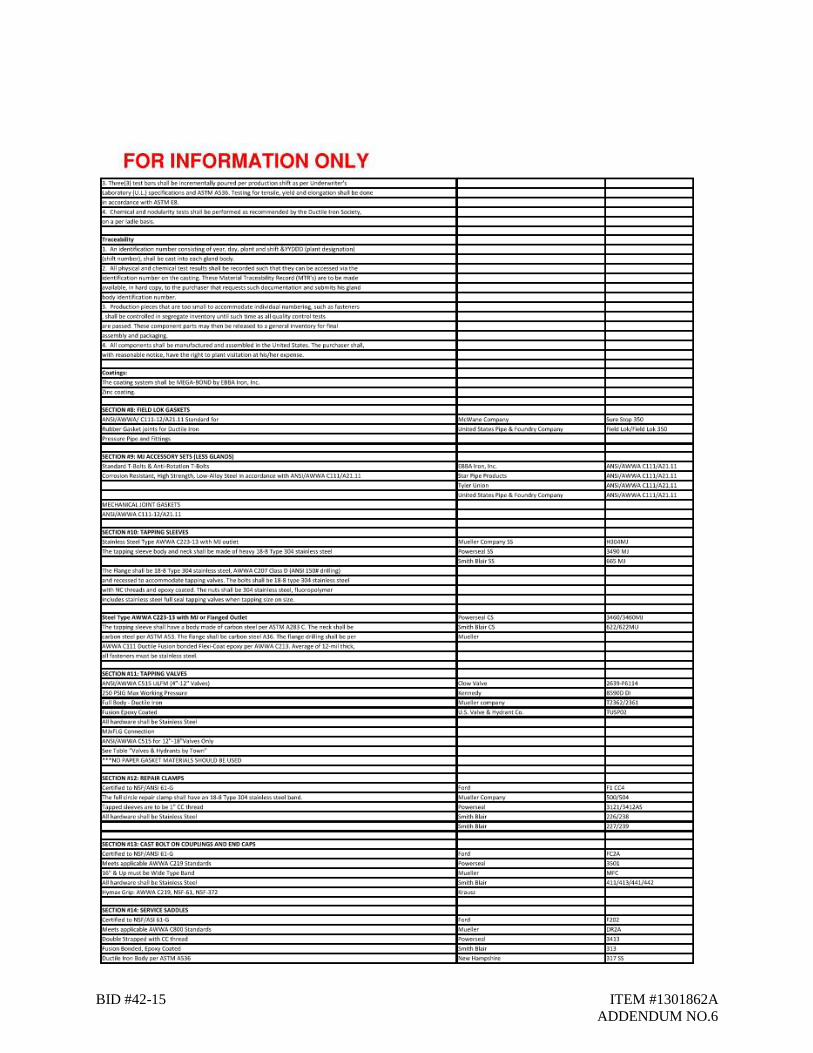
BID #42-15 ITEM #1301862A
ADDENDUM NO.6
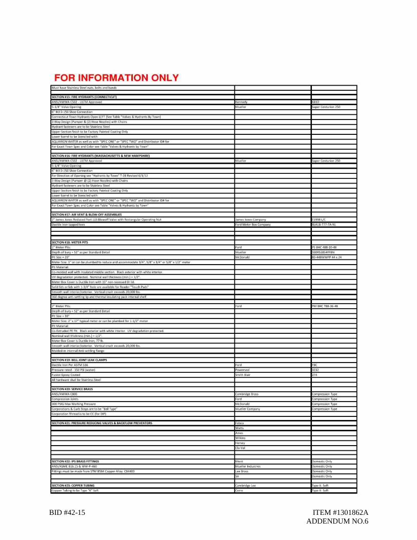
BID #42-15 ITEM #1301862A
ADDENDUM NO.6
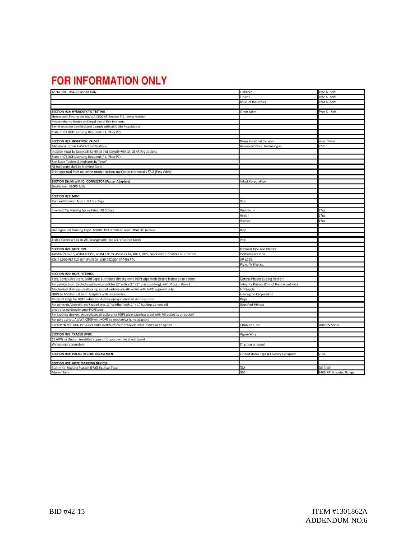
BID #42-15 ITEM #1301862A
ADDENDUM NO.6

Rev. 11/21
BID #42-15 ITEM #1301900A
ADDENDUM NO.6
ITEM 1301900A – HYDROSTATIC PRESSURE TEST
Description:
Work under this section shall include furnishing all labor, materials, tools, and equipment
necessary for performing the Hydrostatic Testing as specified in AWWA C600-05 Section 5.2,
latest revision. The Contractor will be responsible for making sure the new main passes the
Hydrostatic Testing.
The Contractor shall supply all tools, labor, equipment and materials necessary for performing the
Hydrostatic Test.
After the completion of the water main installation, Aquarion will chlorinate and fill the main with
water for disinfection. After a satisfactory test by Aquarion’s Water Quality Department, the
Contractor shall perform a Hydrostatic Test on the new main. Aquarion personnel must be on-site
to witness the test.
The test pressure shall not be less than 1.25 times the stated working pressure of the pipeline
measured at the highest elevation along the test section and not less than 1.5 times the stated
working pressure at the lowest elevation of the test section.
The testing allowance shall be defined as the maximum quantity of makeup water that is added
into a pipeline undergoing hydrostatic pressure testing, or any valved section thereof, in order to
maintain pressure within 5 psi +/- of the specified test pressure (after the pipeline has been filled
with water and the air has been expelled). No pipeline installation will be accepted if the quantity
of makeup water is greater than that determined by the following formula:
L = SD√P
148,000
Where:
L = testing allowance (makeup water), in gallons per hour
S = length of pipe tested, in feet
D = nominal diameter of the pipe, in inches
P = average test pressure during the hydrostatic test, in pounds per square inch (gauge)
For purposes of the Hydrostatic Test, the test pressure in the main shall be maintained for a period
of two (2) hours.
All leaks due to errors in installation shall be repaired by the Contractor at his expense until the
requirements of the Hydrostatic Testing are met.
Materials:
All materials necessary to complete the Hydrostatic Testing shall be provided by the Contractor.

Rev. 11/21
BID #42-15 ITEM #1301900A
ADDENDUM NO.6
Construction Methods:
All construction methods shall conform to AWWA C600-05 Section 5.2, latest revision.
Method of Measurement:
Hydrostatic Testing shall be measured for payment per each hydrostatic test performed.
Performing a re-test of the hydrostatic test shall not be measured for payment.
Basis of Payment:
Hydrostatic Testing will be paid for at the contract unit price per each hydrostatic test performed.
Performing a re-test of the hydrostatic test will not be reimbursed.
Pay Item Pay Unit
Hydrostatic Pressure Test EA
Rev. 11/21
BID #42-15 ITEM #1302229A
ADDENDUM NO.6
ITEM #1302229A – 12” x 16” TAPPING SLEEVE AND VALVE
Description:
Work under this item shall consist of securing and coordinating with a specialty contractor and all
supporting work required for the furnishing and installing of the tapping sleeve and valve. The
Town Contractor’s work under this section shall include, but not necessarily be limited to,
excavation, trenching, shoring, dewatering, backfilling, compaction, concrete thrust block,
grading, and installing the supplied valve box and setting the box to proper grade.
Materials:
The Jack Farrelly Company will supply the valve box lid, top and bottom section, tapping sleeve
and valve and install the tapping sleeve and valve. The valve box shall be installed by the Town’s
Contractor. All other materials required for this installation shall be supplied by the Town’s
Contractor.
Construction Methods:
The tap is to be made with drilling/tapping machine specially designed for intended work, which
must be in good working condition. The Town’s Contractor shall be responsible to schedule and
complete any specified special test pits sufficiently in advance of the tapping of the water main to
obtain actual outside diameter of existing water pipe to be tapped to allow the Farrelly Co. adequate
time to order and obtain the proper size tapping sleeve.
The tapping sleeve and valve are to be installed by the Jack Farrelly Co. in conformance with
manufacturer's instructions and as approved by Aquarion Representative. Before tapping the main,
the pipe exterior, tapping saddle, valve and drilling/cutting tools are to be cleaned and disinfected
using a chlorine solution; the tapping sleeve and valve are to be visually inspected. The tapping
sleeve and valve shall be hydrostatically pressure tested with water after installation at 150 psi for
a minimum of 15 minutes to ensure that the tapping sleeve and valve are not leaking.
The tapping sleeve and valve, including mechanical joint glands, are to be wrapped with
polyethylene encasement and sealed with polyethylene tape. Special attention is to be paid to
backfill material placed under the valve to ensure that it is properly compacted for correct bedding
of the valve. To prevent any deflection of the tapping sleeve installation due to thrust pressure, a
cast-in-place concrete thrust block is to be constructed between tapping sleeve and undisturbed
soil to brace and support the tapping sleeve independently of the water main.
The Town’s Contractor shall be responsible to properly align and install the valve box during the
backfilling of the tapping sleeve and valve excavation.

Rev. 11/21
BID #42-15 ITEM #1302229A
ADDENDUM NO.6
Method of Measurement:
This work shall be measured for payment by the number of tapping sleeves, including valve and
valve box and cover, excavated and installed. Excavation, backfill, shoring, concrete thrust block
and valve box installation for this work will not be measured for payment.
Basis of Payment:
Payment for a tapping sleeve and valve of the size specified shall be paid for at the contract unit
price each, complete in place, which price shall include all excavation, backfill, shoring, concrete
thrust block, valve box installation and for specialty services and materials provided by Jack
Farrelly Company.
Payment for the specialty services provided by the Jack Farrelly Company will be made by the
Town’s Contractor for each tapping sleeve installed and accepted.
Pay Item Pay Unit
12” x 16” Tapping Sleeve and Valve EA.

Rev. 11/21
BID #42-15 ITEM #1302901A
ADDENDUM NO.6
ITEM 1302901A – AIR RELIEF VALVE (WATER MAIN)
Description:
Work under this section shall include all labor, tools, materials, and equipment necessary to furnish
and install the 2” Air Relief Valve, complete as shown in the Standard Details or as directed by
the Aquarion Representative.
Work under this section shall include all labor, tools, materials, and equipment necessary for:
obtaining road opening permit, if required by the Engineer
coordination of Call-Before-You-Dig mark out
saw-cutting of the roadway, sidewalks, or driveways
traffic control equipment (signs, barriers, etc.)
traffic control coordination, including scheduling of policemen and flagmen
furnishing and maintaining lighting
mobilization and demobilization
clearing and grubbing
excavation as measured from the existing grade to the trench subgrade
concrete thrust block installation, if required
furnishing, installing, operating and maintaining a dewatering system
furnishing, installing and removing sheeting, bracing and trench boxes
furnishing, stockpiling, loading, hauling, placing and compacting pipe bedding material
backfill and compaction of excavations
stockpiling, loading, hauling and legally disposing of surplus material
unloading and storage of pipe, fittings, and valves
installing pipe, fittings, joint restraint assemblies, and restrained joint pipe
asphalt and concrete pavement removal and disposal
removal and restoration of walls, fences, signs and any other structures which must be
removed to carry out the work
removal of topsoil and sod; restoration of area to original condition upon completion of
work
care and protection of existing pipes, utilities, and other structures
piling and storage of excavated materials
Materials:
Materials for Air Relief Valve assemblies include, but are not limited to, ductile iron tapped tees,
brass accessories including a James Jones valve, or approved equal, 15” PVC riser pipe, cast iron
blow-off box, blow-off box cover, and any concrete blocking necessary to provide a suitable base
for supporting the 15” PVC riser pipe. Blow-off assemblies at dead ends shall include a
mechanical joint plug, restraints and hardware.

Rev. 11/21
BID #42-15 ITEM #1302901A
ADDENDUM NO.6
The Contractor shall order materials based on the Aquarion List of Approved Materials.
Additional materials, if required, must be approved by the Aquarion Representative at the site in
order to be invoiced. There shall be no administrative mark up on additional materials ordered.
Construction Methods:
The Air Relief Valve shall be installed as shown on the drawings or as directed by the Aquarion
Representative. Air Relief Valve installations shall conform to the Aquarion Standard Details.
Abandonment of Air Relief Valves shall include making sure the valve is in the off position,
excavating, removing the blow-off box and lid, removing or cutting the 15” PVC down to a level
below existing grade to the satisfaction of the Aquarion Representative, and backfilling the
excavation with approved bedding and backfill material. The abandonment of Air Relief Valves
also includes removal of the old Air Relief Valve and the installation of a plug into the water main.
The air vent/blow-off shall no longer be visible at the surface and shall be reported to Utility
Operations as abandoned and no longer in service.
Installing an Air Relief Valve on an existing main shall include excavation and cleaning of the
existing main. All debris and buildup shall be removed from the existing main so it is smooth.
The existing main shall then be tapped and the appropriate hardware and accessories installed and
brought to the surface using the materials and methods as specified herein.
All Air Relief Valve boxes shall be set so that they are centered over the valve and standpipe.
Method of Measurement:
Work under this section for the size and type specified, will be measured for payment per each Air
Relief Valve (Water Main) furnished and installed, complete in place, and accepted.
Bedding material furnished, installed, and compacted, to the bedding material limits shown on the
Typical Trench Detail, will not be measured separately for payment, but shall be included in the
cost per each air relief valve installed. Brass accessories including a James Jones valve, or
approved equal, 15” PVC riser pipe, cast iron blow-off box, blow-off box cover, and any concrete
blocking necessary to provide a suitable base for supporting the 15” PVC riser pipe will not be
measured for separate payment, but shall be included in the cost of the air relief valve.
Excavation and Disposal of Unsuitable Material will not be measured for separate payment, but
shall be included in the cost of the air relief valve.
Rock In Trench, Temporary Pavement Repair and Permanent Pavement Replacement will be
measured separately for payment under those appropriate Items.

Rev. 11/21
BID #42-15 ITEM #1302901A
ADDENDUM NO.6
Basis of Payment:
Work under this section for the size and type specified, will be paid for at the contract unit price
per each Air Relief Valve (Water Main) furnished, installed, complete in place, and accepted.
No separate payment will be made for bedding material furnished, installed, and compacted, to the
bedding material limits shown on the Typical Trench Detail, but shall be included in the cost per
each Air Relief Valve installed.
No separate payment will be made for Excavation and Disposal of Unsuitable Material, but shall
be included in the cost per each Air Relief Valve installed.
Rock In Trench, Additional Backfill Material, Temporary Pavement Repair and Permanent
Pavement Replacement will be paid for separately at the contract unit price under those appropriate
Items.
Pay Item Pay Unit
Air Relief Valve (Water Main) EA
Rev. 11/21
BID #42-15 ITEM #1303202A
ADDENDUM NO.6
ITEM #1303202A – HYDRANT ASSEMBLY (WATER MAIN)
Description:
Work under this section shall consist of the installation of hydrant assemblies where shown on
the in conformance with Item 5 of the Aquarion Technical Specifications.
Materials:
The Contractor shall furnish materials based on the “List of Approved Materials” attached to
special provision #1301862A – Furnish Pipe, Valves and Miscellaneous Fittings (Water Main).
Additional materials, if required, shall be provided by the Contractor and shall be ordered by the
Contractor from his material supplier. Additional materials must be approved by the Aquarion
Representative at the site.
Construction Methods:
Construction methods shall conform to Item 5 of the Aquarion Technical Specifications.
Method of Measurement:
This work shall be measured for payment by the unit, complete in place and ready for operation.
Measurement for payment shall conform to Item 5 of the Aquarion Technical Specifications.
Basis of Payment:
Payment for the hydrant assembly shall be by the contract unit price each, complete in place,
which price shall include all materials, equipment, tools and labor incidental thereto.
Pay Item Pay Unit
Hydrant Assembly (Water Main) EA.
Rev. 11/21
BID #42-15 ITEM #1304111A
ADDENDUM NO.6
ITEM #1304111A – CLASS “C” CONCRETE (WATER MAIN)
Description:
Work under this section shall consist of the furnishing and placing of concrete for thrust blocks
and anchors in the locations shown on the plans or as required by the Aquarion details. This
work is more fully detailed under Item 6 of the Aquarion Technical Specifications.
Materials:
Material shall conform to the requirements of Item 6 of the Aquarion Technical Specifications.
Construction Methods:
Concrete for thrust blocks and anchors shall be placed in conformance with the Aquarion
Standard details. For pipe larger than 16-inch diameter and other cases not covered by the
Aquarion details, a special design shall be provided by the Contractor for each situation
encountered. Such special design details shall be signed and sealed by a registered professional
engineer.
Method of Measurement:
Measurement of this work shall conform to Item 6 of the Aquarion Technical Specifications.
Basis of Payment:
Payment for concrete for thrust blocks and anchors shall conform to Item 6 of the Aquarion
Technical Specifications. No separate payment will be made for any required reinforcement, tie
rods, fittings or engineering.
Pay Item Pay Unit
Class “C” Concrete (Water Main) C.Y.

Rev. Date 10-21
BID #42-15 ITEM #1400102A, #1400104A,
#1403001A, #1403007A
ADDENDUM NO.6
ITEM # 1400102A – 8” POLYVINYL CHLORIDE PIPE (SANITARY
SEWER)
ITEM # 1400104A – 12” POLYVINYL CHLORIDE PIPE (SANITARY
SEWER)
ITEM #1403001A - MANHOLE (SANITARY SEWER)
ITEM # 1403007A – SPECIAL SANITARY MANHOLE (SANITARY
SEWER)
DESCRIPTION: The work under this Item shall consist of removal of existing sanitary sewers,
construction of new gravity sanitary sewers, installation of manholes and fittings, connections to
existing sewer facilities, temporary shoring, flowable fill and sheeting, temporary dewatering,
backfilling, abandoning existing sewers and manholes, testing, and final location surveys for
sanitary sewers. All sanitary sewer work shall meet the City of Shelton Water Pollution Control
Authority (WPCA) requirements.
MATERIALS:
Materials shall include pipes, bedding, manholes, fittings, chimneys, backfill, detector tape, and
other accessory items.
1.1 PIPES AND FITTINGS
A. PVC Sewer Pipe and Fittings: According to the following:
1. PVC Sewer Pipe and Fittings, 15” Diameter and Smaller: ASTM D 3034 or ASTM F-
1760; SDR 35, bell and spigot type with retained ring gasket joints.
a. Gaskets: ASTM F 477, elastomeric seals.
2. PVC Sewer Pipe and Fittings, 24” Diameter: AWWAC900, Class 200 PVC pipe with
bell and spigot ends for gasketed joints
a. Gaskets: ASTM F 477, elastomeric seals.
B. PVC Sanitary Sewer Pipe and Fittings; 24” Diameter (C-905): AWWA Blue Transmission
C905 Pressure Class 235 Psi, DR=18, meeting the requirements of AWWA C905 with
gaskets meeting ASTM F477, and joints in compliance with ASTD D3139. Maximum pipe

Rev. Date 10-21
BID #42-15 ITEM #1400102A, #1400104A,
#1403001A, #1403007A
ADDENDUM NO.6
length is 20 feet. Steel sheeting to be left in place shall be of suitable strength to allow and
support the excavation to depths indicated.
C. DIP Class 52 for applications where the depth of bury is either greater than 15 feet or less than
four feet. Maximum pipe length of 6.5 feet (6” lateral).
1.2 BEDDING AND BACKFILL MATERIAL
A. Bedding shall be ¾” crushed stone conforming to the requirements of Section M.01.01 for No.6
stone of the State of Connecticut Department of Transportation “Standard Specifications for
Roads, Bridges and Incidental Construction”, Form 818, including current supplemental.
1.3 GEOTEXTILE FABRIC
A. Drainage Fabric: Nonwoven geotextile, specifically manufactured as a drainage geotextile;
made from polyolefins, polyesters, or polyamides; and with the following minimum
properties determined according to ASTM D 4759 and referenced standard test methods:
1. Grab Tensile Strength: 110 lbf; ASTM D 4632.
2. Tear Strength: 40 lbf; ASTM D 4533.
3. Puncture Resistance: 50 lbf ; ASTM D 4833.
4. Water Flow Rate: 150 gpm per sq. ft.; ASTM D 4491.
5. Apparent Opening Size: No. 50; ASTM D 4751.
1.4 MANHOLES
A. Normal-Traffic Precast Concrete Manholes: ASTM C 478, precast, reinforced concrete, of
depth indicated, with provision for rubber gasketed joints.
1. Diameter: 48 inches minimum, interior diameter as indicated. Diameter for main trunk
manholes along Route 34 to be 72 inches minimum, unless otherwise indicated.
2. Ballast: Increase thickness of precast concrete sections or add concrete to base section,
as required to prevent flotation.
3. Base Section: 6-inch minimum thickness for floor slab and 6-inch minimum thickness
for walls and base riser section, and having separate base slab or base section with
integral floor.
4. Riser Sections: 6-inch minimum thickness, and lengths to provide depth indicated.
5. Top Section: Eccentric-cone type, unless concentric-cone or flat-slab-top type is
indicated. Top of cone of size that matches grade rings.
6. Gaskets: ASTM C 443, rubber.
7. Grade Rings: Include two or three reinforced-concrete rings, of 6- to 9-inch total
thickness, that match 24-inch- diameter frame and cover.
8. Steps: Fiberglass, individual steps or ladder. Include width that allows worker to place
both feet on one step and is designed to prevent lateral slippage off step. Cast or anchor
Rev. Date 10-21
BID #42-15 ITEM #1400102A, #1400104A,
#1403001A, #1403007A
ADDENDUM NO.6
into base, riser, and top section sidewalls with steps at 12- to 16-inch intervals. Omit
steps for manholes less than 60 inches deep.
9. Steps: ASTM C 478, individual steps or ladder. Omit steps for manholes less than 60
inches deep.
10. Flexible, Watertight Pipe Connectors: ASTM C 923, resilient, of size required, for each
pipe connecting to base section.
B. Manhole Frames and Covers: ASTM A 536, Grade 65-45-12, ductile-iron castings designed for
heavy-duty service. Include 36-inch ID by 8-inch riser with 4-inch minimum width flange,
and 24-inch- diameter cover. Include indented top design with lettering "SHELTON
SANITARY SEWER" cast into cover as manufactured by Campbell Foundry, pattern No.
1221, LeBaron Foundry Pattern LJ1025 (East Jordan Iron Works), Laperle Foundry Pattern
3521.
1.5 CONCRETE
A. General: Cast-in-place concrete according to ACI 318, ACI 350R, and the following:
1. Cement: ASTM C 150, Type II.
2. Fine Aggregate: ASTM C 33, sand.
3. Coarse Aggregate: ASTM C 33, crushed gravel.
4. Water: Potable.
B. Portland Cement Design Mix: 4000 psi minimum, with 0.45 maximum water-cementitious
materials ratio.
1. Reinforcement Fabric: ASTM A 185, steel, welded wire fabric, plain.
2. Reinforcement Bars: ASTM A 615/A 615M, Grade 60, deformed steel.
C. Structure Channels and Benches: Factory or field formed from concrete. Portland cement
design mix, 4000 psi minimum, with 0.45 maximum water-cementitious materials ratio.
Include channels and benches in manholes.
1. Channels: Concrete invert, formed to same width as connected piping, with height of
vertical sides to three-fourths of pipe diameter. Form curved channels with smooth,
uniform radius and slope.
2. Invert Slope: 1 percent through manhole.
3. Benches: Brick, sloped to drain into channel slope: 4 percent.
1.6 PROTECTIVE COATINGS
A. Description: One- or two-coat, coal-tar epoxy; 15-mil minimum thickness, unless otherwise
indicated; factory or field applied to the following surfaces:
1. Concrete Manholes: On exterior surface.
2. Manhole Frames and Covers: On surfaces that will be exposed to sewer gases.
Rev. Date 10-21
BID #42-15 ITEM #1400102A, #1400104A,
#1403001A, #1403007A
ADDENDUM NO.6
1.7 CHIMNEYS
A. Chimneys shall be precast sewer chimneys as manufactured by Superior Products Distributors,
Inc., Milldale, CT, or equal. The materials incorporated into the precast chimney shall be
4,000 psi concrete, cement per ASTM C150-81, reinforcing per ASTM A615, captive “O”
rings and captive seal unit gaskets shall be vulcanized natural rubber or vulcanized synthetic
rubber and PVC fittings per ASTM D3034.
1.8 PIPE COUPLINGS AND ADAPTERS
A. Fernco Serres 1002-242RC/1818RC or approved equal with stainless steel shear rings and
clamps.
SUBMITTALS:
A. Product Data and Shop Drawings: For the following:
1. DIP Fittings – Ductile Iron to PVC Fittings and Pipe.
2. PVC – Sewer Pipe and Fittings.
3. Connection fittings and miscellaneous products.
4. Precast Concrete Manholes, waterproof coatings, waterproof boots, etc.
5. Manhole Brick, Block, and Riser Rings.
6. Precast Concrete Chimneys.
7. Manhole Frames and Covers.
8. Clean-out Frames and Covers.
9. Metallic Detector Tape.
10. Initial Backfill.
11. Pipe Bedding.
12. Steel sheeting to be left in place.
B. Coordination Drawings: Show manholes and other structures, pipe sizes, locations, and
elevations. Include details of underground structures and connections. Show other piping in
same trench and clearances from sewerage system piping. Indicate interface and spatial
relationship between piping and proximate structures.
C. Coordination Profile Drawings: Show system piping in elevation. Draw profiles at horizontal
scale of not less than 1 inch equals 20 feet and vertical scale of not less than 1 inch equals 4
feet. Indicate underground structures and pipe. Show types, sizes, materials, and elevations
of other utilities crossing system piping.
D. Design Mix Reports and Calculations: For each class of cast-in-place concrete, and flowable
fill.
Rev. Date 10-21
BID #42-15 ITEM #1400102A, #1400104A,
#1403001A, #1403007A
ADDENDUM NO.6
E. Field Test Reports: Indicate and interpret test results for compliance with performance
requirements. Tests to include materials, compaction, cleaning, CCTV recordings, air-
leakage, and other tests required.
DELIVERY, STORAGE, AND HANDLING:
A. Do not store plastic structures, pipe, and fittings in direct sunlight.
B. Protect pipe, pipe fittings, and seals from dirt and damage.
C. Handle precast concrete manholes and other structures according to manufacturer's written
rigging instructions.
CONSTRUCTION METHODS: The sanitary sewers shall be installed as indicated on the
plans.
2.1 EARTHWORK
A. Excavating, trenching, and backfilling are specified in Division II, Form 818.
2.2 IDENTIFICATION
A. Install green warning tape directly over piping and at outside edges of underground structures.
1. Use metallic detectable warning tape (Green), marked “Sanitary Sewer” placed 12 inches
over nonferrous piping and over edges of underground structures.
2.3 PIPING APPLICATIONS
A. General: Include watertight joints.
B. Refer to Part 2 of this Section for detailed specifications for pipe and fitting products listed
below. Use pipe, fittings, and joining methods according to applications indicated.
2.4 SPECIAL PIPE COUPLING AND FITTING APPLICATIONS
A. Special Pipe Couplings and Adapters: Use where required to join piping and no other
appropriate method is specified. Do not use instead of specified joining methods.
1. Use the following pipe couplings for nonpressure applications:
a. Sleeve type to join piping, of same size, or with small difference in OD.
b. Increaser/reducer-pattern, sleeve type to join piping of different sizes.

Rev. Date 10-21
BID #42-15 ITEM #1400102A, #1400104A,
#1403001A, #1403007A
ADDENDUM NO.6
c. Bushing type to join piping of different sizes where annular space between smaller
piping's OD and larger piping's ID permits installation.
2.5 INSTALLATION, GENERAL
A. General Locations and Arrangements: Drawing plans and details indicate general location and
arrangement of underground sanitary sewerage piping. Location and arrangement of piping
layout shall take design considerations into account. Install piping as indicated, to extent
practical.
B. Install piping beginning at low point, true to grades and alignment indicated with unbroken
continuity of invert. Place bell ends of piping facing upstream. Install gaskets, seals,
sleeves, and couplings according to manufacturer's written instructions for using lubricants,
cements, and other installation requirements. Maintain swab or drag in line, and pull past
each joint as it is completed.
1. Maximum Slope = 10% (0.100 ft/ft)
2. Minimum Slope = 2.0% (0.020 ft/ft for 4” pipe)
3. Minimum Slope = 1.0% (0.010 ft/ft for 6” pipe)
4. Minimum Slope = 0.5% (0.005 ft/ft for 8 inch pipe)
5. Minimum Slope = 0.3% (0.003 ft/ft for 12 inch pipe)
6. Minimum Pipe Diameter = 6” (laterals)
7. Minimum Pipe Diameter = 8” (mains)
8. Minimum Cover Depth = 36” to top of 6” lateral.
C. Use manholes for changes in direction, unless fittings are indicated. Use fittings for branch
connections, unless direct tap into existing sewer is indicated.
D. Use proper size increasers, reducers, and couplings where different sizes or materials of pipes
and fittings are connected. Reducing size of piping in direction of flow is prohibited.
1. Install gravity-flow piping and connect to building's sanitary drains, of sizes and in
locations indicated. Terminate piping as indicated.
E. Extend sanitary sewerage piping and laterals to connect to existing sewer mains or building's
sanitary drains, of sizes and in locations indicated. Terminate piping as indicated.
2.6 PIPE JOINT CONSTRUCTION AND INSTALLATION
A. General: Join and install pipe and fittings according to installations indicated.
B. PVC Sewer Pipe and Fittings: As follows:
1. Join pipe and gasketed fittings with gaskets according to ASTM D 2321.
Rev. Date 10-21
BID #42-15 ITEM #1400102A, #1400104A,
#1403001A, #1403007A
ADDENDUM NO.6
2. Join profile sewer pipe fittings with gaskets according to ASTM D 2321 and
manufacturer's written instructions.
3. Install according to ASTM D 2321.
4. Bed pipe on compacted crushed stone at building foundation excavation to avoid
differential settlement.
C. System Piping Joints: Make joints using system manufacturer's couplings, unless otherwise
indicated.
D. Join piping made of different materials or dimensions with couplings made for this application.
Use couplings that are compatible with and that fit both systems' materials and dimensions.
E. Concrete encase sanitary sewer at water main and storm sewer crossings where there is less than
1 foot of clearance. Provide bond breaker between water main and sanitary encasement.
F. Install with top surfaces of components, except piping, flush with finished surface.
G. Trench Backfill; Initial Backfill to one foot above the sanitary sewer shall be crushed stone in
accord with the latest Shelton WPCA standards and requirements. The remainder of the
trench backfill shall be in accord with the latest Shelton WPCA/D.P.W. standards and
requirements. Install flowable fill initial backfill on 24” C-905 PVCP on deep sections of
pipe, with lower sections of sheeting to be left in place. Compact backfill in 8” lifts to 95%
Maximum Dry Density as determined by ASTM D-1557 (Modified Proctor) Test.
H. Pavement Repair; Pavement removal and/or replacement shall be in accord with the CT DOT
pavement restoration standards and requirements, and as shown on the contract documents.
2.7 MANHOLE INSTALLATION
A. General: Install manholes, complete with appurtenances and accessories indicated.
B. Form continuous concrete channels and benches between inlets and outlet.
C. Set tops of frames and covers flush with finished surface of manholes that occur in pavements.
Set tops 3 inches above finished surface elsewhere, unless otherwise indicated. Install
frames on 2 courses (minimum) of brick and mortar. Maximum distance to first step to be 2
feet.
D. Install precast concrete manhole sections with gaskets according to ASTM C 891 in accord with
the latest Shelton WPCA standards and requirements. Compact backfill to 95% Maximum
Dry Density as determined by ASTM D-1557 (Modified Proctor) Method.
E. Special Manholes (Drop Manhole): standard precast outside drop manholes in accord with the
latest Shelton WPCA standards and requirements. Manholes designated as Inside Drop
shall be formed within the manhole (Inside Drop Manhole).
Rev. Date 10-21
BID #42-15 ITEM #1400102A, #1400104A,
#1403001A, #1403007A
ADDENDUM NO.6
F. Manhole Inverts; construct using red clay brick in in workman-like manned to a height of 0.80
pipe diameter, As Ordered By Engineer (A.O.B.E.). Provide smooth hydraulic transitions
and slope benches toward channel. Poured concrete inverts are not allowed.
G. Install precast chimneys similar to precast concrete manholes and according to manufacturers
recommendations and industry standards A.O.B.E. Base section shall be of bridge and base
pad design..
H. Install precast tanks, manholes, and oil separator and crushed stone foundation bed as shown.
Install concrete anti-floatation bed and anchor straps for oil water separator.
2.8 CONCRETE PLACEMENT
A. Place cast-in-place concrete according to ACI 318 and ACI 350R.
2.9 CLOSING ABANDONED SANITARY SEWERAGE SYSTEMS
A. Abandon Piping: Close open ends of abandoned underground piping indicated to remain in
place to be watertight with mortar plug or grout. Include closures strong enough to
withstand hydrostatic and earth pressures that may result after ends of abandoned piping
have been closed. Abandon existing laterals back to main and remove or grout pipes:
1. The sewer lateral shall be cut at the main line, install a plumber’s stop, and cover with
concrete or As Ordered By Engineer (A.O.B.E.)
2. Excavate test pits at ends of existing laterals to verify location and depth. Reconstruct
existing laterals and chimney connections if necessary to meet proposed pipe inverts.
3. Crush and remove existing sanitary pipe to be replaced with new sanitary sewer.
B. Abandon Manhole: Excavate around structure as required:
1. Remove manhole structure completely and close open ends of remaining piping.
2. Backfill to grade according to Section 312001 "Earthwork."
2.10 FIELD QUALITY CONTROL
A. Pipe Material; ASTM D-2412.
B. Preconstruction Meeting; prior to the start of construction the Contractor, Engineer, and Owner
shall meet with representatives of the Shelton WPCA to ensure compliance with City
requirements.
C. City Coordination: contact the Shelton WPCA at least 48 hours prior to beginning work to
schedule construction inspections, installation, building connections, abandonments, and
test procedures.
Rev. Date 10-21
BID #42-15 ITEM #1400102A, #1400104A,
#1403001A, #1403007A
ADDENDUM NO.6
D. Clear interior of piping and structures of dirt and superfluous material as work progresses.
Maintain swab or drag in piping, and pull past each joint as it is completed.
1. Place plug in end of incomplete piping at end of day and when work stops.
2. Flush piping between manholes and other structures to remove collected debris, if
required by authorities having jurisdiction.
E. Inspect interior of piping to determine whether line displacement or other damage has occurred.
Inspect after approximately 24 inches of backfill is in place, and again at completion of
Project.
1. Submit separate reports for each system inspection.
2. Defects requiring correction include the following:
a. Alignment: Less than full diameter of inside of pipe is visible between structures.
b. Deflection: Flexible piping with deflection that prevents passage of ball or
cylinder of size not less than 92.5 percent of piping diameter.
c. Crushed, broken, cracked, or otherwise damaged piping.
d. Infiltration: Water leakage into piping.
e. Exfiltration: Water leakage from or around piping.
3. Replace defective piping using new materials, and repeat inspections until defects are
within allowances specified.
4. Reinspect and repeat procedure until results are satisfactory.
F. Test new piping systems, and parts of existing systems that have been altered, extended, or
repaired, for leaks and defects.
1. Do not enclose, cover, or put into service before inspection and approval.
2. Test completed piping systems according to authorities having jurisdiction.
3. Schedule tests and inspections by authorities having jurisdiction with at least 24 hours'
advance notice.
4. Submit separate reports for each test to the proper authorities for record.
5. If authorities having jurisdiction do not have published procedures, perform tests as
follows:
a. Sanitary Sewerage: Perform hydrostatic test:
1) Allowable leakage is maximum of 50 gal. per inch of nominal pipe size per
mile of pipe, during 24-hour period.
2) Close openings in system and fill with water.
3) Purge air and refill with water.
4) Disconnect water supply.
5) Test and inspect joints for leaks.
6) Option: Test ductile-iron piping according to AWWA C600, Section
"Hydrostatic Testing." Use test pressure of at least 10 psig.

Rev. Date 10-21
BID #42-15 ITEM #1400102A, #1400104A,
#1403001A, #1403007A
ADDENDUM NO.6
b. Sanitary Sewerage: Perform air test according to UNI-B-6 and Connecticut Public
Health Code Regulations and Technical Standards for Subsurface Sewage Disposal
Systems, January 8, 2009 or latest revision; Section III.B “Procedure for Air
Leakage Pressure Testing of Sewer Pipe”:
1) Prepare a low-pressure air test for new PVC sanitary sewer mains between
manholes with a minimum pressure of 3.5 p.s.i. held for 5 minutes with no
drop in pressure.
2) Option: Test concrete piping according to ASTM C 924.
6. Manholes: Perform hydraulic test according to ASTM C 969.
7. Leaks and loss in test pressure constitute defects that must be repaired.
8. Replace leaking piping using new materials, and repeat testing until leakage is within
allowances specified.
9. Visual inspection and photographs of sanitary sewer laterals.
G. Video Inspection; All new sanitary sewer mains shall be video inspected in accordance
with latest Shelton WPCA procedures. The line shall be flushed and a dye solution allowed
to flow immediately prior to the video inspection. Any deficiencies shall be noted in and
report and provided to the City along with a DVD copy of the recording.
H. As-Built Drawing/Survey; Prepare an As-Built drawing/map upon completion of work
(within two weeks) and submit to the Engineer and Shelton WPCA for their records. The
As-Built drawing from the Contractor shall contain horizontal and vertical location of
chimneys, manholes, laterals, mains, etc. with tape ties and inverts, pavement thicknesses,
cover depth, size and depth of utilities crossed, any relocated utilities.
I. In addition to the As-Built Drawing, the Contractor shall also submit a Final Location
Survey to the Architect and Utility Company when the final building is completed. The
Final Location Survey shall be prepared by a Land Surveyor licensed in Connecticut in both
reproducible hard copies, and electronic AutoCAD format.
J. A video TV inspection (DVD recording) of all new sanitary sewer mains and a written
report must also be submitted to the Engineer and Shelton WPCA after construction but
prior to beginning use.
MAINTENANCE: Contractor shall maintain existing sanitary sewer flows in existing sewers
and laterals prior to acceptance of the new sanitary sewers by the Shelton WPCA.
Contractor shall coordinate service connections and temporary shut downs with the Engineer and
Shelton WPCA.
METHOD OF MEASUREMENT: This work will be measured for payment as follows:
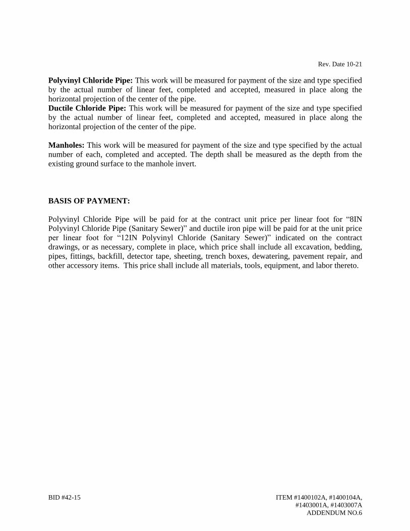
Rev. Date 10-21
BID #42-15 ITEM #1400102A, #1400104A,
#1403001A, #1403007A
ADDENDUM NO.6
Polyvinyl Chloride Pipe: This work will be measured for payment of the size and type specified
by the actual number of linear feet, completed and accepted, measured in place along the
horizontal projection of the center of the pipe.
Ductile Chloride Pipe: This work will be measured for payment of the size and type specified
by the actual number of linear feet, completed and accepted, measured in place along the
horizontal projection of the center of the pipe.
Manholes: This work will be measured for payment of the size and type specified by the actual
number of each, completed and accepted. The depth shall be measured as the depth from the
existing ground surface to the manhole invert.
BASIS OF PAYMENT:
Polyvinyl Chloride Pipe will be paid for at the contract unit price per linear foot for “8IN
Polyvinyl Chloride Pipe (Sanitary Sewer)” and ductile iron pipe will be paid for at the unit price
per linear foot for “12IN Polyvinyl Chloride (Sanitary Sewer)” indicated on the contract
drawings, or as necessary, complete in place, which price shall include all excavation, bedding,
pipes, fittings, backfill, detector tape, sheeting, trench boxes, dewatering, pavement repair, and
other accessory items. This price shall include all materials, tools, equipment, and labor thereto.
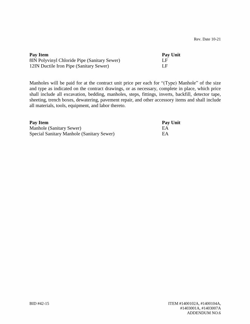
Rev. Date 10-21
BID #42-15 ITEM #1400102A, #1400104A,
#1403001A, #1403007A
ADDENDUM NO.6
Pay Item Pay Unit
8IN Polyvinyl Chloride Pipe (Sanitary Sewer) LF
12IN Ductile Iron Pipe (Sanitary Sewer) LF
Manholes will be paid for at the contract unit price per each for “(Type) Manhole” of the size
and type as indicated on the contract drawings, or as necessary, complete in place, which price
shall include all excavation, bedding, manholes, steps, fittings, inverts, backfill, detector tape,
sheeting, trench boxes, dewatering, pavement repair, and other accessory items and shall include
all materials, tools, equipment, and labor thereto.
Pay Item Pay Unit
Manhole (Sanitary Sewer) EA
Special Sanitary Manhole (Sanitary Sewer) EA

APPENDIX A

STANDARD TECHNICAL SPECIFICATIONS
FOR PIPELINE PROJECTS
LAST REVISED OCTOBER 1, 2021
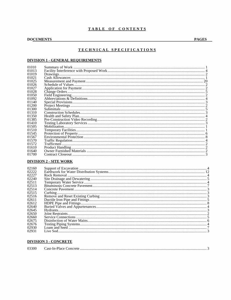
T A B L E O F C O N T E N T S DOCUMENTS PAGES T E C H N I C A L S P E C I F I C A T I O N S DIVISION 1 - GENERAL REQUIREMENTS 01010 Summary of Work .......................................................................................................................................... 1 01013 Facility Interference with Proposed Work ...................................................................................................... 4 01019 Drawings ......................................................................................................................................................... 2 01021 Cash Allowances ............................................................................................................................................ 1 01025 Measurement and Payment ........................................................................................................................... 20 01026 Schedule of Values ......................................................................................................................................... 2 01027 Application for Payment ................................................................................................................................. 2 01028 Change Orders ................................................................................................................................................ 5 01050 Field Engineering ............................................................................................................................................ 2 01092 Abbreviations & Definitions ........................................................................................................................... 4 01140 Special Provisions ........................................................................................................................................... 3 01200 Project Meetings ............................................................................................................................................. 2 01300 Submittals ....................................................................................................................................................... 5 01310 Construction Schedules................................................................................................................................... 3 01350 Health and Safety Plan .................................................................................................................................... 4 01385 Pre-Construction Video Recording ................................................................................................................. 2 01410 Testing Laboratory Services ........................................................................................................................... 3 01505 Mobilization .................................................................................................................................................... 1 01510 Temporary Facilities ....................................................................................................................................... 1 01545 Protection of Property ..................................................................................................................................... 6 01567 Environmental Protection ............................................................................................................................... 8 01570 Traffic Regulation ........................................................................................................................................... 4 01572 Trafficmen ...................................................................................................................................................... 2 01610 Product Handling ............................................................................................................................................ 2 01640 Owner Furnished Materials ............................................................................................................................ 2 01700 Contract Closeout ........................................................................................................................................... 3 DIVISION 2 - SITE WORK 02160 Support of Excavation ...................................................................................................................................... 4 02222 Earthwork for Water Distribution Systems ..................................................................................................... 12 02227 Rock Removal .................................................................................................................................................. 4 02240 Site Drainage and Dewatering .......................................................................................................................... 5 02511 Temporary Water Service ................................................................................................................................. 4 02513 Bituminous Concrete Pavement ........................................................................................................................ 7 02514 Concrete Pavement ........................................................................................................................................... 3 02515 Curbing ............................................................................................................................................................. 3 02516 Remove and Reset Existing Curbing ................................................................................................................ 3 02611 Ductile Iron Pipe and Fittings ........................................................................................................................... 5 02612 HDPE Pipe and Fittings .................................................................................................................................... 8 02640 Buried Valves and Appurtenances .................................................................................................................... 4 02645 Hydrants............................................................................................................................................................ 3 02650 Joint Restraints.................................................................................................................................................. 2 02660 Service Connections ......................................................................................................................................... 5 02675 Disinfection of Water Mains ............................................................................................................................. 6 02676 Testing Piping Systems ..................................................................................................................................... 4 02930 Loam and Seed ................................................................................................................................................. 7 02931 Live Sod ............................................................................................................................................................ 3 DIVISION 3 - CONCRETE 03300 Cast-In-Place Concrete ..................................................................................................................................... 3

SUMMARY OF WORK 12/8/2017 01010-1
SECTION 01010
SUMMARY OF WORK
PART 1 GENERAL
1.01 WORK COVERED BY CONTRACT DOCUMENTS
A. The Work of this Contract generally consists of the installation of water main and required appurtenances as shown on the Contract Drawings and outlined in these specifications.
B. Furnishing, assembling, and removing temporary facilities, if required to complete the project as shown on the Contract Drawings.
C. The Contractor shall be responsible for furnishing all materials and appurtenances required to complete the project as shown on the Contract Drawings, with the exception of piping materials.
D. All work within the Town/ State jurisdiction shall not commence until approval is
received by the Contractor from the Town/ State in which the work under this contract is being performed.
1.02 CONTRACT
A. Construct the Work under a unit item contract as presented in Section 00300 Bid Form.
PART 2 PRODUCTS (Not Applicable)
PART 3 EXECUTION (Not Applicable)
END OF SECTION

FACILITY INTERFERENCE WITH PROPOSED WORK 12/7/2018 01013-1
SECTION 01013
FACILITY INTERFERENCE WITH PROPOSED WORK
PART 1 GENERAL
1.01 LOCATION OF UNDERGROUND FACILITIES
A. Facilities and other underground locations shown on the Drawings are from the
best sources available to the Owner at the time of this Contract preparation and
are furnished only for information and convenience of the Contractor and are
not guaranteed.
1. It is agreed and understood that the Owner does not warrant or
guarantee that the subsurface locations of existing pipes, structures or
other underground phenomena actually encountered during construction
shall be the same as those shown on the Drawings.
2. It is further agreed and understood that the Contractor shall not use or be
entitled to use any of the information made available to him on the plans
or obtained in any examination made by him as a basis of any claim or
demand against the Owner or the Engineer, because of any variance
between the information made available and the subsurface locations of
natural phenomena, existing pipes or other structures as actually
encountered during the construction work, except as may otherwise be
provided for this Section.
3. In general, main line facilities only are shown and not individual
connections from main line to buildings.
4. The presence of a structure along a proposed pipeline generally
indicates that there will be a corresponding connection to it from
whatever main line facilities are in the street.
5. The Contractor shall take all necessary steps, including field inspections
and consultations with the Utility Owner and Property Owners, to insure
that the most up to date information and accurate information available is
used to mark the field location of the facilities, including service
connections, prior to construction.
1.02 RELATED WORK
A. Documents affecting work of this Section include, but are not necessarily limited
to, General Conditions, Supplementary Conditions, and Sections in Division 1 of
these Specifications.

FACILITY INTERFERENCE WITH PROPOSED WORK 12/7/2018 01013-2
1.03 PIPE LOCATIONS
A. Pipelines and structures installed under this Contract will be located
substantially as indicated on the Drawings. The Engineer reserves the right to
make such modifications in location and grade as may be found desirable to
avoid interference with existing structures and/or facilities or to avoid
unsatisfactory locations, all as he may see fit as in the best interests of the
Owner. 1. Contract unit prices shall apply.
B. The locations of pipes, valves, hydrants and any other appurtenances or items included in the work shall not be modified without the written approval of the Engineer.
1.04 PROTECTION OF UNDERGROUND FACILITIES AND DAMAGES THERETO
A. The Contractor shall notify "Call Before You Dig / Dig Safe" of his operations at
least 72 hours prior to construction on any portion of the project. 1. The Contractor shall notify all utility companies of his operations
sufficiently in advance of construction and take all measures necessary
to avoid damage or undue interruption to the utilities' normal services. 2. Utility poles shall be supported by the Contractor as designated on the
Contract Drawings, Specifications, or as directed by the utilities' owner and all costs shall be included in the contract unit prices with no
additional cost to the Aquarion Water Company.
3. Utility Poles shall be supported unless the owner of the utility pole states in writing that bracing is not necessary.
4. No additional compensation shall be allowed because of damage to facilities due to test pit excavation.
1.05 CONDITION OF EXISTING FACILITIES
A. In general, poor physical condition of existing facilities shall not be an
acceptable basis for claiming additional compensation. 1. Further, protection or repair of existing facilities outside of the Trench
Width shall not be considered as a valid basis for additional
compensation. 2. The Contractor shall take all prudent steps to make himself aware of the
physical condition of the existing facilities expected to be encountered,
and to adjust his operations accordingly.
PART 2 PRODUCTS (Not Applicable)
PART 3 EXECUTION
3.01 INTERFERENCE AND RELOCATION OF FACILITIES
A. INTERFERENCE BY UTILITIES
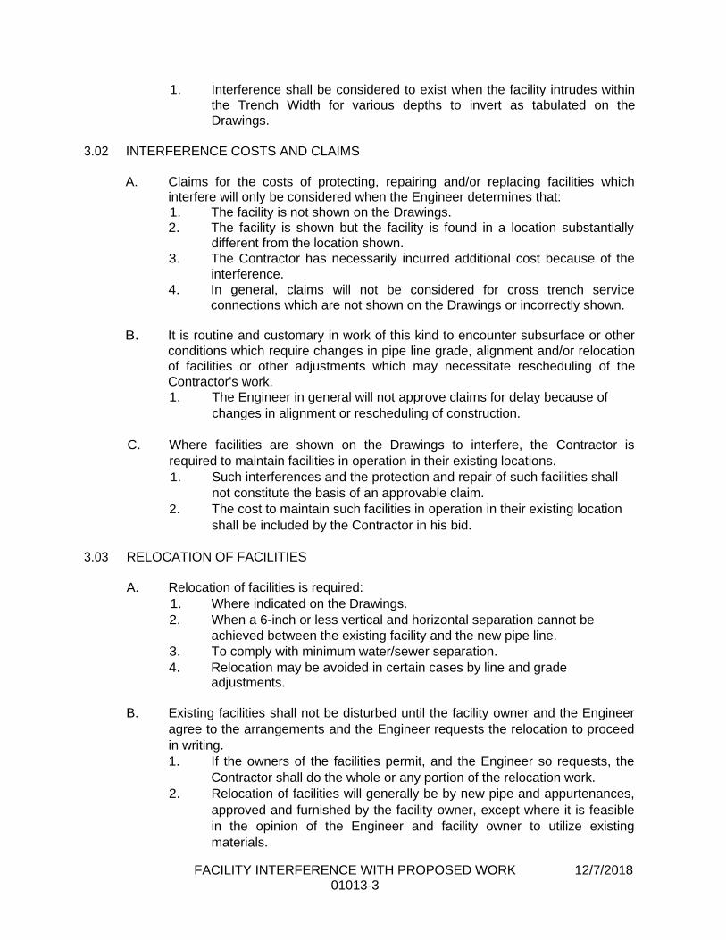
FACILITY INTERFERENCE WITH PROPOSED WORK 12/7/2018 01013-3
1. Interference shall be considered to exist when the facility intrudes within
the Trench Width for various depths to invert as tabulated on the
Drawings.
3.02 INTERFERENCE COSTS AND CLAIMS
A. Claims for the costs of protecting, repairing and/or replacing facilities which
interfere will only be considered when the Engineer determines that: 1. The facility is not shown on the Drawings.
2. The facility is shown but the facility is found in a location substantially
different from the location shown.
3. The Contractor has necessarily incurred additional cost because of the
interference.
4. In general, claims will not be considered for cross trench service connections which are not shown on the Drawings or incorrectly shown.
B. It is routine and customary in work of this kind to encounter subsurface or other
conditions which require changes in pipe line grade, alignment and/or relocation
of facilities or other adjustments which may necessitate rescheduling of the
Contractor's work.
1. The Engineer in general will not approve claims for delay because of
changes in alignment or rescheduling of construction.
C. Where facilities are shown on the Drawings to interfere, the Contractor is
required to maintain facilities in operation in their existing locations.
1. Such interferences and the protection and repair of such facilities shall
not constitute the basis of an approvable claim.
2. The cost to maintain such facilities in operation in their existing location
shall be included by the Contractor in his bid.
3.03 RELOCATION OF FACILITIES
A. Relocation of facilities is required:
1. Where indicated on the Drawings.
2. When a 6-inch or less vertical and horizontal separation cannot be
achieved between the existing facility and the new pipe line.
3. To comply with minimum water/sewer separation.
4. Relocation may be avoided in certain cases by line and grade adjustments.
B. Existing facilities shall not be disturbed until the facility owner and the Engineer
agree to the arrangements and the Engineer requests the relocation to proceed
in writing.
1. If the owners of the facilities permit, and the Engineer so requests, the
Contractor shall do the whole or any portion of the relocation work.
2. Relocation of facilities will generally be by new pipe and appurtenances,
approved and furnished by the facility owner, except where it is feasible
in the opinion of the Engineer and facility owner to utilize existing
materials.
FACILITY INTERFERENCE WITH PROPOSED WORK 12/7/2018 01013-4
3. If so requested by the facility owner, the Engineer may direct the
Contractor to furnish the material.
4. All removed materials remain the property of the facility owner.
3.04 RELOCATION COSTS AND CLAIMS
A. All costs of temporary relocations for the Contractor's convenience shall be
borne by the Contractor.
B. Relocation costs for all facilities specified on the Drawings to be relocated shall
be the responsibility of the Contractor and be included in the Contractor's bid
prices, including those specifically for facility relocations, if such are included.
C. Relocation costs for publicly owned facilities not specified on the Drawings to be
relocated, but directed to be relocated by the Engineer in writing, shall be paid in
accordance with General Conditions Par. 4.04, B.
D. Relocation costs for privately owned utilities for which relocation is required by
the work of this Contract, will not be approved by the Engineer for payment as
Extra Work.
E. Exceptions as determined by the Engineer shall be paid in accordance with
General Conditions Par. 4.04, B.
3.05 PRIVATE FACILITY COMPANY CLAIM DISTINCTIONS
A. Claims against the Owner by the Contractor for the cost of delays or damage
repair sustained by the Contractor because of damage to or interferences
between privately owned public facilities and the proposed work will not be
considered valid for additional compensation.
1. Claims involving privately owned facilities must be settled between the
Contractor and the facility owner.
B. The Owner reserves the right to exercise, or not to exercise, any rights he may
have to require relocation of privately owned public facilities at the facility
company's expense in case of interferences.
1. If the Owner does not exercise such rights, no claims against the Owner
for not exercising such rights shall be approved by the Engineer.
3.06 FACILITY SERVICE CONNECTIONS AND WORK
A. The Contractor shall make all arrangements with the facility companies for
temporary and permanent services and relocations required under this Contract,
subject to the conditions described elsewhere in these Specifications.
1. Facility companies in the area of work, and/or expected to provide
service to the work, shall be arranged for and if required paid for at no
additional expense to the Owner.
END OF SECTION

DRAWINGS 12/2/2020 01019-1
SECTION 01019
DRAWINGS
PART 1 GENERAL 1.01 DESCRIPTION
A. The Contract Drawings may be modified by addenda and shall be issued for
construction purposes.
1. These Drawings may be supplemented or superseded by such additional general and detail drawings as may be necessary and desirable as the
work progresses.
2. The Drawings issued for construction at that time or after the signing of the Contract Documents shall become the Contract Drawings.
B. Dimensions:
1. Except where noted, the Drawings are made to scale, but all working
dimensions shall be taken from the figured dimensions or by actual
measurements at the work, and in no case by scaling the prints.
2. The Contractor shall study and compare all Drawings and verify all figures before laying out or constructing the work and shall be responsible for any
and all errors in the Contract work which might have been avoided thereby.
3. The Contractor shall take all measurements of existing established
conditions notwithstanding the figured dimensions on the Drawings.
4. When figured dimensions are not in agreement with the Contractor's
measurements, the Engineer shall be immediately notified and the Engineer will promptly adjust the same.
5. Whether or not an error is believed to exist, deviations from the Drawings
and the dimensions given thereon shall be made only after approval in writing is obtained from the Engineer.
C. Diagrammatic Drawings:
1. Plans or Drawings where the work is shown diagrammatically indicate
approved working systems. Every piece of material, fittings, fixtures or
small equipment is not shown, nor every difficulty or interference that may be encountered to carry out the true intent and purpose of the Contract
Documents.
2. All necessary parts to make complete, approved working systems or installation shall be included as if detailed on these Drawings.
3. The location of pipe lines and appurtenances shown on the Drawings, unless exactly dimensioned, shall be considered as approximate only.
4. The Contractor shall adjust the position of the pipe lines and
appurtenances in accordance with good working practices to meet
interferences, provide proper clearance and provide proper access space
for operation and maintenance.
DRAWINGS 12/2/2020 01019-2
D. Typical Details:
1. Where shown on the Drawings, typical details shall apply to each and every item of the Contract work where such items are incorporated and the
detail is applicable. 2. Unless noted otherwise, such typical details shall be applicable in full.
E. Copies of Drawings Furnished:
1. Copies of the Contract Drawings and Specifications are available for download at the Owner’s electronic procurement site.
PART 2 PRODUCTS (Not Applicable)
PART 3 EXECUTION
3.01 EXISTING AND ADJACENT CONDITIONS
A. Wherever existing conditions or construction not required as part of the work of
the Contract are shown, they are so shown as a source of information only. The
Engineer, while believing such information is substantially correct, assumes no
responsibility thereof.
1. Before starting any work that might be affected by such existing
construction or conditions, the Contractor shall have made himself familiar
with all conditions affecting the nature and manner of performing the work,
and shall not be entitled to any extra compensation for any work or
expense arising from or caused by his neglect to have verified all existing
conditions and requirements.
3.02 DISCREPANCIES
A. If, during the performance of the Work, Contractor discovers any conflict, error,
ambiguity, or discrepancy within the Contract Documents or between the Contract
Documents and any provision of the Law or Regulation applicable to the perfor-mance of the Work or of any standard, specification, manual or code, or of any
instruction of any Supplier, Contractor shall report it to ENGINEER in writing at
once. Contractor shall not proceed with the Work affected thereby, except in an emergency, until an amendment or supplement to the Contract Documents has
been issued; provided, however, that Contractor shall not be liable to OWNER or ENGINEER for failure to report any such conflict, error, ambiguity, or discrepancy
unless Contractor knew or reasonably should have known thereof. Any work
performed after such discovery without the approval of the Engineer, shall be at the risk and expense of the Contractor.
B. In the event that a conflict between the Contract Drawings and Specifications is
discovered, the stricter requirement will govern, as directed by the Engineer.
END OF SECTION
CASH ALLOWANCES 12/8/2017 01021-1
SECTION 01021
CASH ALLOWANCES
PART 1 GENERAL
1.01 DESCRIPTION
A. Work included: To provide adequate budget and bonding to cover items not
precisely determined by the Owner prior to bidding, allow within the proposed Contract Sum the amounts described below.
1.02 RELATED WORK
A. Documents affecting work of this Section include, but are not necessarily limited
to, General Conditions, Supplementary Conditions, and Sections in Division 1 of these Specifications. 1. Section 01025 Measurement and Payment.
1.03 TYPICAL CASH ALLOWANCES
A. Typical cash allowances will be the following items. The amount of the allowance will be designated on the bid form under its respective item. 1. Traffic Control (Uniformed Police) 2. Traffic Control (Certified Flagger) 3. Compaction Testing 4. Additional Piping Materials 5. Repairing Sewer Services 6. Permits
B. Stated allowances shall be paid as specified in Section 01025, Measurement and Payment. 1. The requirement for competitive bids is waived. 2. The dollar amount stated is only approximate. 3. Whether the approved expenses are more or less, the Contractor shall be
reimbursed by the Owner the actual approved costs as billed. PART 2 PRODUCTS (Not Applicable)
PART 3 EXECUTION (Not Applicable)
END OF SECTION

MEASUREMENT AND PAYMENT 10/1/2021 01025-1
SECTION 01025
MEASUREMENT AND PAYMENT
PART 1 GENERAL
1.01 DESCRIPTION
A. The purpose of this Section is to define the method of measurement and payment
for each of the unit prices or lump sums listed in the Bid Proposal. If no bid item appears in the Bid Proposal for any of the following described items, no work of that description is anticipated on the project. 1. The Contractor shall thoroughly review the work required for each
payment item. 2. The Contractor shall have included in his various bid items, an amount to
cover costs for additional work which may be necessary, to construct the water mains in the close proximity of underground facilities, services, poles and other facilities which may exist.
3. The discovery of an underground facility during the construction, not shown on the Contract Drawings shall not constitute automatic initiation of a change order. Changes in pipe line, grade and length for the avoidance of interference with underground utilities or obstructions shall be measured and paid for under the contract bid items. The additional work to cross or pass this underground facility must be substantial for consideration for additional payment. a. The word "substantial" as used above shall mean that an additional
amount of work is required, beyond the work that is normally required in the crossing or paralleling of an underground facility.
B. Work shall be measured and paid for using quantities as specified in this section. In the event that a discrepancy is noted in the Bid Form, this section shall govern. It is the responsibility of the bidder to notify the Owner if any discrepancy is found.
1.02 RELATED WORK
A. Documents affecting the work of this Section include General Conditions,
Supplementary Conditions, and all Divisions of these Specifications.
1.03 TRENCH PAYMENT LIMITS
A. The measurements for trench payment limits shall be used for the volume of
computing excavation below grade. 1. Trench limits in earth and rock shall be measured within vertical lines. The
measured lines shall not exceed a width shown in the Typical Trench Detail in the Aquarion Water Company Standard Details.
2. Grade shall be measured vertically from the surface of the existing ground to a maximum point of four (4) inches below the bottom of the pipe, for trenches in earth.
MEASUREMENT AND PAYMENT 10/1/2021 01025-2
a. In trenches where rock is encountered, grade shall be six (6) inches below the bottom of the pipe.
3. In paved roadways the trench width at the roadway surface shall not exceed a width of six (6) feet.
4. If the Owner orders additional excavation below normal grade to remove unsuitable material, the removal of the unsuitable material and the replacement with suitable material will be considered for payment under Item No. 31, Additional Backfill Material.
1.04 EARTH EXCAVATION FOR PIPELINE TRENCHES
A. Earth excavation for pipeline trenches from the existing ground surface to pipe
sub-grade shall not be paid for separately, and all costs for this excavation shall be included in the unit prices paid for the various pipe laying items.
1.05 NIGHT WORK A. Night work for connections, water main installation, taps, water services, etc. shall
be performed at no additional cost to the Owner.
1.06 ADDITIONAL EXCAVATION
A. Additional excavation directed or approved by the Engineer that is not included under other Items of this Contract shall be paid for under Item 34: Test Pits and Additional Excavation. Unauthorized excavation, excavation to remove unsuitable material below the vertical payment limits, excavation performed for the Contractor’s convenience, excavation performed for work included under other Items of this Contract, or excavation unusable due to the Contractor’s activities will not be eligible for payment under this item. Refer to Item 34 for work included for payment under this Item.
B. Additional excavation shall include but not necessarily be limited to scheduled excavations performed with the intent of installing pipe fittings, valves, tapping sleeves, making connections to water mains or appurtenances, and water service connections where the work could not be completed due to unforeseen circumstances. The Contractor shall be compensated under Item 34 and shall have no other grounds for compensation where excavations were performed for work that could not be completed.
1.07 TRENCH BRACING AND SUPPORT
A. All costs for furnishing, installing and removing sheeting, bracing or the use of a
steel support box shall be included in the various pipe laying items.
MEASUREMENT AND PAYMENT 10/1/2021 01025-3
1.08 PIPE BEDDING
A. All costs for stockpiling, loading, hauling, placing and compacting pipe bedding
shall be included in the various pipe-laying items.
1.09 SURPLUS MATERIAL
A. All costs for stockpiling, loading, hauling and legal disposing of surplus material
shall be included in the various pipe laying items.
1.10 DEWATERING
A. All costs for furnishing, installing and operating a dewatering system shall be
included in the various pipe laying items. The Contractor shall comply with any environmental permits for the project relating to handling and disposal of trench water.
1.11 EXCESS EXCAVATED MATERIAL
A. All costs for transporting, placing and compacting excess material obtained within this Contract shall be included in the various pipe laying items.
1.12 CRUSHED STONE BEDDING, BANK-RUN SAND AND GRAVEL
A. There will be no separate measurement or payment for furnishing and placing,
crushed stone bedding, bank run sand and gravel. The cost of such materials and work shall be included in the unit price for the various pipe laying items.
1.13 PRESSURE/LEAKAGE TESTING
A. No separate payment shall be made for labor, materials, tools and equipment
necessary for or incidental to the performance of the pressure/leakage tests of the water main and its appurtenances. The costs associated with pressure/leakage testing shall be included in the unit price for the various pipe-laying items.
1.14 REMOVING AND STACKING OF HYDRANTS & GATE VALVES
A. No separate payment shall be made for labor, materials, tools and equipment necessary for or incidental to the removal of and stacking of the designated hydrant(s) or gate valves locations determined by the Owner. The cost for this item shall be included in the unit price for the various pipe-laying items.

MEASUREMENT AND PAYMENT 10/1/2021 01025-4
1.15 CAPPING AND ABANDONMENT (IN-PLACE) OF OLD MAINS
A. No separate payment shall be made for labor, materials, tools and equipment
necessary for or incidental to the capping of and abandonment (in-place) of the water mains and valves including closing valves, removing valve boxes and pavement replacement. The cost for this item shall be included in the unit price for the various pipe-laying items.
1.16 RESTORATION OF DAMAGED AREAS
A. All costs for restoration of damaged areas, including but not necessarily limited,
to existing sidewalks, curbs, aprons and driveways, shrubs, trees, stone walls, ornamental fencing, Belgian block curbs, aprons and driveways, and lawns, shall be included in the unit price for the various pipe-laying items. All damaged areas shall be restored to pre-construction conditions.
B. All public or private monuments, iron pipes or other types of property line and
geodetic markers damaged or disturbed by operations under this Contract shall be reset by a licensed land surveyor, all at no additional cost to the Owner. All other work under this Section, shall not be paid separately, but shall be considered incidental to the work and included in the unit price and lump sum items.
1.17 UNIFORMED POLICE OFFICERS
A. Measurement and payment for traffic persons shall be at hourly rate for the Police
Department of the Owner as billed to the Contractor. The allowance in Section 00300, "Bid Form", is approximate. If the uniformed police traffic control expenses are greater or less, the Contractor shall be reimbursed for and limited to the actual cost billed for properly ordered and approved traffic control.
B. The Police Department will generally bill the Contractor weekly, and the Contractor
shall pay the Police Department bills within a ten (10) working day period for uniformed Police Officers provided on the job site. The billing shall include a weekly statement outlining the days worked, hours worked, location of the work and rate for all officers providing service during that billing period. The Police Chief must sign all bills.
C. Traffic persons ordered by the Contractor for his convenience or unforeseen
problems which are not part of the original project shall be paid at his own expense.
D. The Contractor is responsible for contacting the Police Department in regards to
scheduling requirements.
E. Uniformed Police Officers required for purposes other than public safety and/or control of traffic shall not be eligible for reimbursement of payment. No payment will be made for overtime traffic persons unless emergency conditions exist. If the Contractor elects to work more than eight (8) hours in one day, or more than forty (40) hours in one week, he shall assume all such costs and will not be reimbursed under any bid item. However, if the Owner approves emergency overtime, the Owner shall pay the Police Department directly for services rendered.
MEASUREMENT AND PAYMENT 10/1/2021 01025-5
1.18 TRAFFIC REGULATION
A. Except for the payment of uniformed police officers as outlined in 1.17, there shall be no separate measurement or payment for the work performed under Section 01570 -Traffic Regulation. All costs for furnishing lighted barricades, variable message boards, and traffic protection devices and for labor, equipment and services involved in the erecting, maintaining, moving, adjusting, relocating and storing of signs, flashers, lights, barricades, traffic cones, traffic delineators and other devices furnished by the Contractor, as well as the cost of all labor and equipment involved in the maintenance of traffic lanes and detours ordered or included in the approved scheme for maintenance of traffic shall be included in the unit price bid for the various pipe laying items.
1.19 MEASUREMENT OF QUANTITIES
A. The quantities of the various items of work performed shall be determined, for
purposes of progress and final payment, by the Contractor and reviewed by the Engineer.
B. The method of measurements to be used in the determination of quantities of the
work of this Contract shall be as specified in this Section. 1. Area Measurements
a. Unless otherwise specified, measurement for area computations shall be made along the surface and taken to the nearest half (1/2) foot.
2. Linear Measurements a. All items such as pipe, service tubing, pavement and curbing, etc.,
shall be made along the alignment of the item, at the surface, and taken to the nearest foot.
3. Volume Measurements - In figuring volumes the following shall apply: a. Test Pits: Measurements shall be taken to the lines and grade
actually excavated. b. Rock and Boulder: Only boulders greater than one half (1/2) cubic
yard in volume and rock as defined in Section 02227, shall be measured for payment. Measurements shall be taken to the lines and grades as specified, in the trench payment limits in this Section.
c. Measurements for payment of concrete shall the lengths, widths, and depths measured in place within the established payment limits. Concrete load tickets shall serve as backup only to document the concrete plants, concrete types, mixtures, dates and times. The quantity on the concrete load ticket shall not serve as basis for payment of concrete.
4. Lump Sum: The term "lump sum" when used as a unit of payment, shall mean complete payment for the work described in the Contract Documents.
5. Per Each: The term "per each" when used as a unit of payment, shall mean complete payment for each unit furnished and installed, completed and accepted, as described in the Contract Documents.
6. Ton: When used as a pavement payment item, shall be determined by the following method:
a. Pavement shall be calculated by measurements of the surface area,
MEASUREMENT AND PAYMENT 10/1/2021 01025-6
within the payment limits, by square yards, times the depth of the pavement, times a factor of 0.056, for a conversion to ton basis.
b. A five (5) percent service factor shall be allowed if a comparison between measurements and delivery slips indicate that additional thickness was placed. If a comparison between delivery slips and measurements indicate less material was placed, the slip quantity shall be used for payment. The Contractor shall submit to the Engineer, one (1) copy of the certified weight slips for all bituminous concrete used in the Work.
1.20 BITUMINOUS CONCRETE PAVEMENT
A. MEASUREMENT 1. Temporary Trench Pavement shall be measured by the actual linear feet
installed along the axis of the pipe as identified in the specifications and on the Drawings. It is the Contractor’s responsibility to place temporary trench pavement to the full width of the pavement disturbed at no additional cost to the Owner. a. Included in this item shall be the adjustment of all castings if
required to finish grade within the trench area.
2. No separate measurement shall be made for cutting of existing pavement,
cutting of edges, tack coating, backfilling, compaction, preparation of subgrade; furnishing and installing additional gravel base course; or disposal of materials.
3. No separate measurement shall be made for furnishing and installing
reflectorized pavement markings; and the removal and resetting manhole frames, gate boxes, catch basins and private utility castings.
4. Any damages outside the planned limit of permanent pavement restoration
shall be the Contractor’s responsibility to repair or replace to the requirements of the Town/ State. The Contractor shall be responsible for any additional restoration due to an escalation of paving requirements caused by the Contractor’s damages, for example, a change in restoration requirements from trench restoration only, to paving a full lane. Damages include, but are not limited to:
a. Excessive trench width b. Undermined pavement from inadequately support trenches c. Scratching or marring of pavement by equipment d. Inadequate sawcutting e. Other conditions reasonably in the Contractor’s control for
prevention, at the Owner’s discretion
5. The Contractor shall place the minimum depth of temporary pavement as required by the Contract Documents. When the Town or Municipality requires temporary pavement be placed to match the depth of the existing pavement thickness and the existing pavement is found to be greater than the specified thickness (+ one half inch), the additional pavement placed

MEASUREMENT AND PAYMENT 10/1/2021 01025-7
beyond the specified thickness shall be measured by the ton. The tonnage of pavement required shall be measured as specified in Item 1.17 of this section and included for payment under Item 39 – Overdepth Temporary Pavement. The tonnage shall be calculated based on the average daily pavement thickness.
6. No separate measurement or payment shall be made for the removal of existing pavement, including bituminous or concrete road base. The removal of any pavement or concrete road base of any thickness shall be included for payment under the various pipe laying items.
7. No separate measurement or payment shall be made for pavement used
for temporary transitions around road plates, raised structures, or transitions between milled and existing portions or roadways, driveways, or entrances.
B. DEFINITIONS OF TEMPORARY AND PERMANENT PAVEMENT 1. Unless specified otherwise with specific reference to this section, the
definitions of temporary and permanent pavement shall be defined as the following. It is the intent of all projects that temporary pavement be placed to the full permanent depth required, with permanent pavement restoration consisting of a pavement structure placed after a mill and overlay of the road surface, full depth temporary trench patch inclusive, is performed. a. Temporary Trench Pavement (Item Nos. 37 and 38) – Pavement
placed along the trench and disturbed areas to the full depth required for permanent installation by the state or municipality in which work is being performed. For example, in state roads where 9” of pavement thickness is required, temporary trench pavement shall be a minimum of 9” in thickness. Pavement placed to a thickness less than what is required for a permanent installation will be considered for the Contractor’s convenience and will not be paid for separately.
b. Permanent Pavement Restoration (Item Nos. 41 and 42) – Pavement structure placed for final restoration, typically after a mill and overlay, to produce a final wearing course over the restoration limits.
c. Work not performed to the requirements of the state or municipality’s requirements will not be eligible for payment.
2. In the event that the state or municipality directs the Contractor to place a temporary pavement thickness that is less than the thickness specified above in the “Definitions of Temporary and Permanent Pavement,” the Contractor must do the following prior to proceeding: 1. Immediately notify the Owner’s Onsite Representative. 2. Immediately notify the Owner and Engineer in writing.
MEASUREMENT AND PAYMENT 10/1/2021 01025-8
3. Receive written correspondence from the State or Municipality directing the Contractor to install temporary pavement at a depth less than specified above in paragraph 1. Any written correspondence from the State or Municipality must be forwarded to the Owner.
4. The Contractor must obtain permission from the Owner in writing. The responsibility of full depth replacement and settlement must be addressed at this time. Any pavement replacement less than full depth is to be done in a manner that does not affect the schedule and final acceptance of the road surface by the authority having jurisdiction.
a. After receiving written permission from the Owner to install
temporary pavement at a different thickness than specified, payment will be at a prorated quantity based on the specified thickness defined in the “Definitions of Temporary and Permanent Pavement.” Payment is calculated as (New Thickness) / (Specified Thickness) X (Unit Price Bid) X (Trench Length).
b. For example: On a Town Road project where 4 inches of Temporary Pavement is called for, the Municipality directs the Contractor to place 2 inches of temporary pavement over the 100 linear foot trench. After all written notifications to the Owner have taken place, the Owner directs (in writing) the Contractor to place temporary pavement to the new 2-inch thickness. If the Contractor’s unit price bid is $10 per linear foot, payment is calculated as follows: (2 inches / 4 inches) X $10 X 100 l.f. = $500.
c. The Contractor will not be paid for any temporary pavement that is
placed to a thickness less than that defined in the “Definitions of Temporary and Permanent Pavement,” without written direction from the Owner.
1.21 DUST CONTROL
A. MEASUREMENT
1. All costs for furnishing, stockpiling, hauling, placing and spread materials required for dust control (i.e. calcium chloride, water) shall be included in the various pipe-laying items.
1.22 PAYMENT
ITEM NO. DESCRIPTION 1. 4-Inch Ductile Iron Water Main and Appurtenances 2. 6-Inch Ductile Iron Water Main and Appurtenances 3. 8-Inch Ductile Iron Water Main and Appurtenances 4. 12-Inch Ductile Iron Water Main and Appurtenances 5. 16-Inch Ductile Iron Water Main and Appurtenances 6. 4-Inch HDPE Water Main and Appurtenances 7. 6-Inch HDPE Water Main and Appurtenances 8. 8-Inch HDPE Water Main and Appurtenances 9. 12-Inch HDPE Water Main and Appurtenances

MEASUREMENT AND PAYMENT 10/1/2021 01025-9
10. 16-Inch HDPE Water Main and Appurtenances 11. 4-Inch Gate Valve 12. 6-Inch Gate Valve 13. 8-Inch Gate Valve 14. 12-Inch Gate Valve 15. 16-Inch Butterfly Valve 16. Tapping Sleeve and Valve for 4-Inch Hole 17. Tapping Sleeve and Valve for 6-Inch Hole 18. Tapping Sleeve and Valve for 8-Inch Hole 19. Tapping Sleeve and Valve for 12-Inch Hole 20. 4-Inch Insertion Valve 21. 6-Inch Insertion Valve 22. 8-Inch Insertion Valve 23. 12-Inch Insertion Valve 24. Hydrant Assembly 25. 2-Inch Blow-Off / Air Vent 26. 1-Inch Water Service Connection and Appurtenances 27. 2-Inch Water Service Connection and Appurtenances 28. 1-Inch Water Service Tubing 29. 2-Inch Water Service Tubing 30. Customer Side Water Services 31. Additional Backfill Material 32. Rock Excavation 33. Controlled Low-Strength Material 34. Test Pits and Additional Excavation 35. Silt Fence 36. Silt Sack 37. Temporary Trench Pavement (Town Road) 38. Temporary Trench Pavement (State Road) 39. Overdepth Temporary Pavement 40. Cold Milling of Pavement 41. Permanent Bituminous Concrete Pavement Restoration (Town Road) 42. Permanent Bituminous Concrete Pavement Restoration (State Road) 43. Permanent Concrete Pavement Restoration 44. Bituminous Lip Curbing 45. Concrete Curbing 46. Permanent Bituminous Concrete Driveway and Sidewalk Restoration 47. Permanent Concrete Driveway and Sidewalk Restoration 48. Loam and Seed 49. Live Sod 50. Replace Traffic Loop Detectors 51. Temporary Water Service 52. Traffic Control (Uniformed Police) 53. Traffic Control (Certified Flagger) 54. Compaction Testing 55. Repair Sewer Service 56. Additional Piping Materials 57. Permits 58. Install New Meter Pit
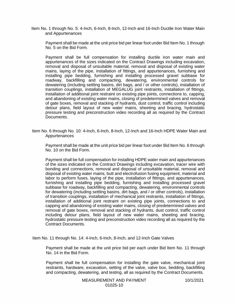
MEASUREMENT AND PAYMENT 10/1/2021 01025-10
Item No. 1 through No. 5: 4-Inch, 6-Inch, 8-Inch, 12-Inch and 16-Inch Ductile Iron Water Main and Appurtenances
Payment shall be made at the unit price bid per linear foot under Bid Item No. 1 through No. 5 on the Bid Form.
Payment shall be full compensation for installing ductile iron water main and appurtenances of the sizes indicated on the Contract Drawings including excavation, removal and disposal of unsuitable material, removal and disposal of existing water mains, laying of the pipe, installation of fittings, and appurtenances, furnishing and installing pipe bedding, furnishing and installing processed gravel subbase for roadway, backfilling and compacting, dewatering, environmental controls for dewatering (including settling basins, dirt bags, and / or other controls), installation of transition couplings, installation of MEGALUG joint restraints, installation of fittings, installation of additional joint restraint on existing pipe joints, connections to, capping, and abandoning of existing water mains, closing of predetermined valves and removal of gate boxes, removal and stacking of hydrants, dust control, traffic control including detour plans, field layout of new water mains, sheeting and bracing, hydrostatic pressure testing and preconstruction video recording all as required by the Contract Documents.
Item No. 6 through No. 10: 4-Inch, 6-Inch, 8-Inch, 12-Inch and 16-Inch HDPE Water Main and Appurtenances
Payment shall be made at the unit price bid per linear foot under Bid Item No. 6 through No. 10 on the Bid Form.
Payment shall be full compensation for installing HDPE water main and appurtenances of the sizes indicated on the Contract Drawings including excavation, tracer wire with bonding and connections, removal and disposal of unsuitable material, removal and disposal of existing water mains, butt and electrofusion fusing equipment, material and labor to perform fuses, laying of the pipe, installation of fittings, and appurtenances, furnishing and installing pipe bedding, furnishing and installing processed gravel subbase for roadway, backfilling and compacting, dewatering, environmental controls for dewatering (including settling basins, dirt bags, and / or other controls), installation of transition couplings, installation of mechanical joint restraints, installation of fittings, installation of additional joint restraint on existing pipe joints, connections to and capping and abandoning of existing water mains, closing of predetermined valves and removal of gate boxes, removal and stacking of hydrants, dust control, traffic control including detour plans, field layout of new water mains, sheeting and bracing, hydrostatic pressure testing and preconstruction video recording all as required by the Contract Documents.
Item No. 11 through No. 14: 4-Inch, 6-Inch, 8-Inch, and 12-Inch Gate Valves
Payment shall be made at the unit price bid per each under Bid Item No. 11 through No. 14 in the Bid Form.
Payment shall be full compensation for installing the gate valve, mechanical joint restraints, hardware, excavation, setting of the valve, valve box, bedding, backfilling and compacting, dewatering, and testing, all as required by the Contract Documents.
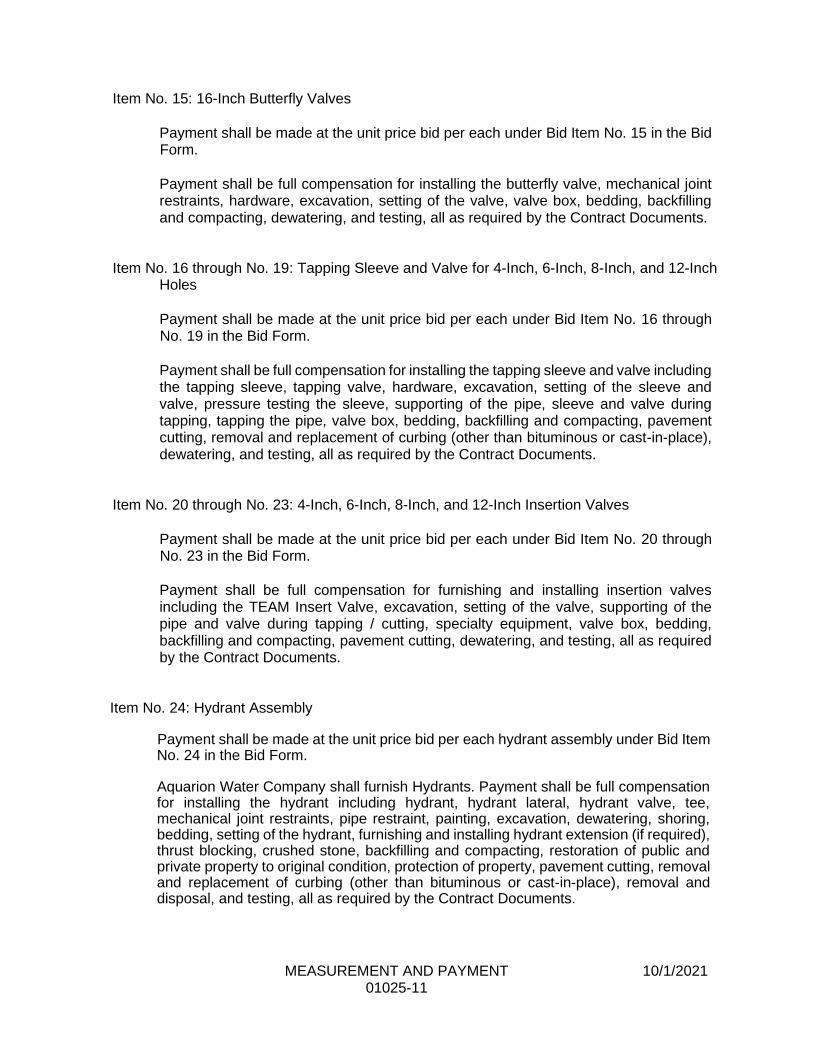
MEASUREMENT AND PAYMENT 10/1/2021 01025-11
Item No. 15: 16-Inch Butterfly Valves
Payment shall be made at the unit price bid per each under Bid Item No. 15 in the Bid Form.
Payment shall be full compensation for installing the butterfly valve, mechanical joint restraints, hardware, excavation, setting of the valve, valve box, bedding, backfilling and compacting, dewatering, and testing, all as required by the Contract Documents.
Item No. 16 through No. 19: Tapping Sleeve and Valve for 4-Inch, 6-Inch, 8-Inch, and 12-Inch
Holes
Payment shall be made at the unit price bid per each under Bid Item No. 16 through No. 19 in the Bid Form.
Payment shall be full compensation for installing the tapping sleeve and valve including the tapping sleeve, tapping valve, hardware, excavation, setting of the sleeve and valve, pressure testing the sleeve, supporting of the pipe, sleeve and valve during tapping, tapping the pipe, valve box, bedding, backfilling and compacting, pavement cutting, removal and replacement of curbing (other than bituminous or cast-in-place), dewatering, and testing, all as required by the Contract Documents.
Item No. 20 through No. 23: 4-Inch, 6-Inch, 8-Inch, and 12-Inch Insertion Valves
Payment shall be made at the unit price bid per each under Bid Item No. 20 through No. 23 in the Bid Form.
Payment shall be full compensation for furnishing and installing insertion valves including the TEAM Insert Valve, excavation, setting of the valve, supporting of the pipe and valve during tapping / cutting, specialty equipment, valve box, bedding, backfilling and compacting, pavement cutting, dewatering, and testing, all as required by the Contract Documents.
Item No. 24: Hydrant Assembly
Payment shall be made at the unit price bid per each hydrant assembly under Bid Item No. 24 in the Bid Form.
Aquarion Water Company shall furnish Hydrants. Payment shall be full compensation for installing the hydrant including hydrant, hydrant lateral, hydrant valve, tee, mechanical joint restraints, pipe restraint, painting, excavation, dewatering, shoring, bedding, setting of the hydrant, furnishing and installing hydrant extension (if required), thrust blocking, crushed stone, backfilling and compacting, restoration of public and private property to original condition, protection of property, pavement cutting, removal and replacement of curbing (other than bituminous or cast-in-place), removal and disposal, and testing, all as required by the Contract Documents.
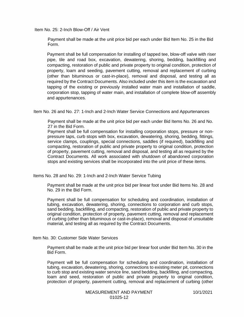
MEASUREMENT AND PAYMENT 10/1/2021 01025-12
Item No. 25: 2-Inch Blow-Off / Air Vent
Payment shall be made at the unit price bid per each under Bid Item No. 25 in the Bid Form.
Payment shall be full compensation for installing of tapped tee, blow-off valve with riser
pipe, tile and road box, excavation, dewatering, shoring, bedding, backfilling and
compacting, restoration of public and private property to original condition, protection of
property, loam and seeding, pavement cutting, removal and replacement of curbing
(other than bituminous or cast-in-place), removal and disposal, and testing all as
required by the Contract Documents. Also included under this item is the excavation and
tapping of the existing or previously installed water main and installation of saddle,
corporation stop, tapping of water main, and installation of complete blow-off assembly
and appurtenances.
Item No. 26 and No. 27: 1-Inch and 2-Inch Water Service Connections and Appurtenances
Payment shall be made at the unit price bid per each under Bid Items No. 26 and No. 27 in the Bid Form. Payment shall be full compensation for installing corporation stops, pressure or non-pressure taps, curb stops with box, excavation, dewatering, shoring, bedding, fittings, service clamps, couplings, special connections, saddles (if required), backfilling and compacting, restoration of public and private property to original condition, protection of property, pavement cutting, removal and disposal, and testing all as required by the Contract Documents. All work associated with shutdown of abandoned corporation stops and existing services shall be incorporated into the unit price of these items.
Items No. 28 and No. 29: 1-Inch and 2-Inch Water Service Tubing
Payment shall be made at the unit price bid per linear foot under Bid Items No. 28 and No. 29 in the Bid Form.
Payment shall be full compensation for scheduling and coordination, installation of tubing, excavation, dewatering, shoring, connections to corporation and curb stops, sand bedding, backfilling, and compacting, restoration of public and private property to original condition, protection of property, pavement cutting, removal and replacement of curbing (other than bituminous or cast-in-place), removal and disposal of unsuitable material, and testing all as required by the Contract Documents.
Item No. 30: Customer Side Water Services
Payment shall be made at the unit price bid per linear foot under Bid Item No. 30 in the Bid Form.
Payment will be full compensation for scheduling and coordination, installation of tubing, excavation, dewatering, shoring, connections to existing meter pit, connections to curb stop and existing water service line, sand bedding, backfilling, and compacting, loam and seed, restoration of public and private property to original condition, protection of property, pavement cutting, removal and replacement of curbing (other
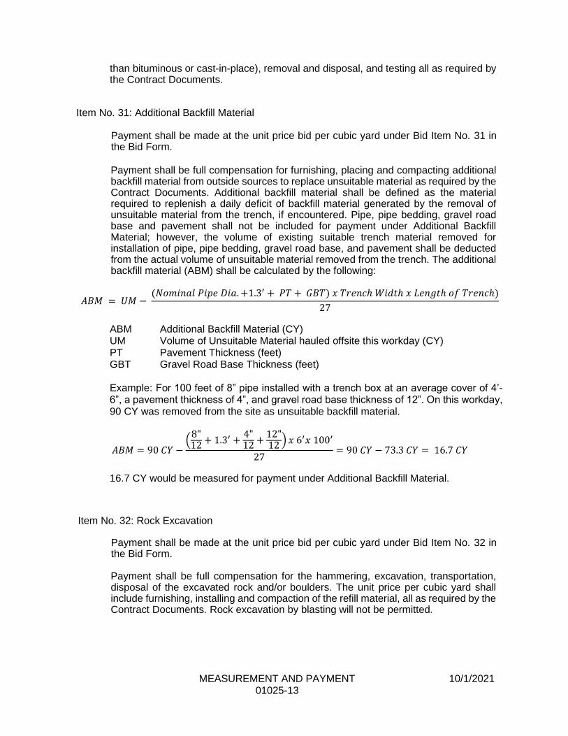
MEASUREMENT AND PAYMENT 10/1/2021 01025-13
than bituminous or cast-in-place), removal and disposal, and testing all as required by the Contract Documents.
Item No. 31: Additional Backfill Material
Payment shall be made at the unit price bid per cubic yard under Bid Item No. 31 in the Bid Form.
Payment shall be full compensation for furnishing, placing and compacting additional backfill material from outside sources to replace unsuitable material as required by the Contract Documents. Additional backfill material shall be defined as the material required to replenish a daily deficit of backfill material generated by the removal of unsuitable material from the trench, if encountered. Pipe, pipe bedding, gravel road base and pavement shall not be included for payment under Additional Backfill Material; however, the volume of existing suitable trench material removed for installation of pipe, pipe bedding, gravel road base, and pavement shall be deducted from the actual volume of unsuitable material removed from the trench. The additional backfill material (ABM) shall be calculated by the following:
𝐴𝐵𝑀 = 𝑈𝑀 − (𝑁𝑜𝑚𝑖𝑛𝑎𝑙 𝑃𝑖𝑝𝑒 𝐷𝑖𝑎. +1.3′ + 𝑃𝑇 + 𝐺𝐵𝑇) 𝑥 𝑇𝑟𝑒𝑛𝑐ℎ 𝑊𝑖𝑑𝑡ℎ 𝑥 𝐿𝑒𝑛𝑔𝑡ℎ 𝑜𝑓 𝑇𝑟𝑒𝑛𝑐ℎ)
27
ABM Additional Backfill Material (CY) UM Volume of Unsuitable Material hauled offsite this workday (CY) PT Pavement Thickness (feet) GBT Gravel Road Base Thickness (feet)
Example: For 100 feet of 8” pipe installed with a trench box at an average cover of 4’-6”, a pavement thickness of 4”, and gravel road base thickness of 12”. On this workday, 90 CY was removed from the site as unsuitable backfill material.
𝐴𝐵𝑀 = 90 𝐶𝑌 −(
8"12 + 1.3′ +
4"12 +
12"12 ) 𝑥 6′𝑥 100′
27= 90 𝐶𝑌 − 73.3 𝐶𝑌 = 16.7 𝐶𝑌
16.7 CY would be measured for payment under Additional Backfill Material.
Item No. 32: Rock Excavation
Payment shall be made at the unit price bid per cubic yard under Bid Item No. 32 in the Bid Form.
Payment shall be full compensation for the hammering, excavation, transportation, disposal of the excavated rock and/or boulders. The unit price per cubic yard shall include furnishing, installing and compaction of the refill material, all as required by the Contract Documents. Rock excavation by blasting will not be permitted.
MEASUREMENT AND PAYMENT 10/1/2021 01025-14
Item No. 33: Controlled Low-Strength Material
Payment shall be made at the unit price bid per cubic yard as measured in place under Bid Item No. 33 in the Bid Form.
Payment shall be full compensation for the furnishing and placing controlled low-strength material including containing / damming, protection during setting including bridging, clean-up and all other work as required by the Contract Documents.
Item No. 34: Test Pits and Additional Excavation
Payment shall be made at the unit price bid per cubic yard under Bid Item No. 34 in the Bid Form.
Payment shall be full compensation for performing test pits and additional excavation as directed or approved by the Engineer, including excavation, furnishing and installing processed gravel subbase for roadway backfilling and compacting, dewatering, environmental controls for dewatering (including settling basins, dirt bags, and / or other controls), temporary pavement restoration, surface restoration, dust control, traffic control including detour plans, sheeting and bracing all as required by the Contract Documents.
Item No. 35: Silt Fence
Payment shall be made at the unit price bid per linear foot under Bid Item No. 35 in the Bid Form.
Payment shall be full compensation for furnishing and placing silt fence including excavation, hay-bales, oak posts, silt fence, maintenance, and the removal and proper disposal of the silt fence at the completion of all work. Where straw wattles (or mulch socks) are permitted by the Engineer, their installation shall be paid for under this item.
Item No. 36: Silt Sack
Payment shall be made at the unit price bid per each under Bid Item No. 36 in the Bid Form.
Payment shall be full compensation for furnishing, installing and maintain the silt sacks, and the removal and proper disposal of the silt sacks after the completion of all work.
Item No. 37: Temporary Trench Pavement (Town Road)
Payment shall be made at the unit price per linear foot as measured along the centerline of the pipe under Bid Item No.37 in the Bid Form. Payment shall be full compensation for all preparatory work and furnishing, placing and compacting the bituminous concrete pavement within town roads as required by the Contract Documents. The price shall include the cost of sawcutting existing pavement to provide a square, straight, clean edge for the new bituminous pavement, the cost of

MEASUREMENT AND PAYMENT 10/1/2021 01025-15
the bituminous material, placement and maintenance of the construction to include additional materials and labor required due to settlement and/or maintenance over a winter shut down, tack coat, cutting or keying of the pavement, removal and resetting all manhole frames, gate boxes, curbs, catch basins, etc.as required by the Contract Documents. Temporary Pavement for test pits shall be included under the Test Pit item. Temporary pavement that is not placed against, square, clean, sawcut edges will not be eligible for payment.
Item No. 38: Temporary Trench Pavement (State Road)
Payment shall be made at the unit price per linear foot as measured along the centerline of the pipe under Bid Item No. 38 in the Bid Form.
Payment shall be full compensation for all preparatory work and furnishing, placing and compacting the bituminous concrete pavement within state roads as required by the Contract Documents. The price shall include the cost of sawcutting existing pavement to provide a square, straight, clean edge for the new bituminous pavement, the cost of the bituminous material placement and maintenance of the construction to include additional materials and labor required due to settlement and/or maintenance over a winter shut down, tack coat, cutting or keying of the pavement, removal and resetting all manhole frames, gate boxes, curbs, catch basins, etc. as required by the Contract Documents. Temporary Pavement for test pits shall be included under the Test Pit item. Temporary pavement that is not placed against, square, clean, sawcut edges will not be eligible for payment.
Item No. 39: Overdepth Temporary Pavement
Payment shall be made at the unit price per Ton under Bid Item No. 39 on the Bid Form. Payment shall be full compensation for all preparatory work and furnishing, placing and compacting the bituminous concrete pavement within town roads as required by the Contract Documents. The price shall include the cost of sawcutting existing pavement to provide a square, straight, clean edge for the new bituminous pavement, the cost of the bituminous material placement and maintenance of the construction to include additional materials and labor required due to settlement and/or maintenance over a winter shut down, tack coat, cutting or keying of the pavement, removal and resetting all manhole frames, gate boxes, curbs, catch basins, etc. as required by the Contract Documents. Temporary Pavement for test pits shall be included under the Test Pit item. Temporary pavement that is not placed against, square, clean, sawcut edges will not be eligible for payment.
Item No. 40: Cold Milling of Pavement
Payment shall be made at the unit price per square yard bid under Bid Item No. 40 in the Bid Form.
Payment shall be full compensation for all labor, tools and materials required for cold milling of bituminous concrete including layout of milling limits, preparatory work, milling
MEASUREMENT AND PAYMENT 10/1/2021 01025-16
of bituminous concrete, saw cutting along limits of milling, mechanical removal of asphalt around structures, hauling and disposal of millings as required by the Contract Documents.
Item No. 41: Permanent Bituminous Concrete Pavement Restoration (Town Road)
Payment shall be made at the unit price per ton bid under Bid Item No. 41 in the Bid Form.
Payment shall be full compensation for all preparatory work and furnishing, placing and compacting the bituminous concrete pavement in town roads as required by the Contract Documents. The price shall include the cost of the bituminous material, placement, tack coat, cutting or keying of the pavement, removal and resetting all manhole frames, gate boxes, curbs, catch basins, application of hot seal between pavement joints, etc.; and the repair of reflectorized pavement markings, as required by the Contract Documents.
Item No. 42: Permanent Bituminous Concrete Pavement Restoration (State Road)
Payment shall be made at the unit price per ton bid under Bid Item No. 42 in the Bid Form.
Payment shall be full compensation for all preparatory work and furnishing, placing and compacting the bituminous concrete pavement in state roads as required by the Contract Documents. The price shall include the cost of the bituminous material, placement, tack coat, cutting or keying of the pavement, removal and resetting all manhole frames, gate boxes, curbs, catch basins, application of hot seal between pavement joints, etc.; and the repair of reflectorized pavement markings, as required by the Contract Documents.
Item No. 43: Permanent Concrete Pavement Restoration
Payment shall be made at the unit price bid per cubic yard as measured in place under Bid Item No. 43 in the Bid Form.
Payment shall be full compensation for all preparatory work and furnishing and installing reinforcing dowels, wire mesh, furnish and placing and the concrete pavement, and furnishing and placing road plates for protection of concrete as required by the Contract Documents. The price shall include removal and disposal of temporary pavement, preparation of subgrade, the cost of the steel reinforcement, concrete, formwork, placement, cutting or keying of the pavement, removal and resetting all manhole frames, gate boxes, curbs, catch basins, etc.; and the repair of reflectorized pavement markings, as required by the Contract Documents.
Item No. 44: Bituminous Lip Curbing Payment shall be made at the unit price per linear foot bid under Bid Item No. 44 in the Bid Form.
MEASUREMENT AND PAYMENT 10/1/2021 01025-17
Payment shall be full compensation for all preparatory work and furnishing and placing the bituminous lip curbing as required by the Contract Documents. The price shall include the cost of the bituminous material, placement, tack coat and cutting or keying of the pavement as required by the Contract Documents.
Item No. 45: Concrete Curbing
Payment shall be made at the unit price per linear foot bid under Bid Item No. 45 in the Bid Form.
Payment shall be full compensation for all preparatory work and furnishing and placing the concrete curbing as required by the Contract Documents. The price shall include the cost of the concrete, saw cutting, excavation, furnishing, placing, and compacting suitable gravel base, assembly of formwork, furnishing and placing concrete, finishing concrete curbing, and backfilling curbing. Replacement of bituminous concrete at faces of curbing as required by the Contract Documents.
Item No. 46: Permanent Bituminous Concrete Driveway and Sidewalk Restoration
Payment shall be made at the unit price per square yard bid under Bid Item No. 46 in the Bid Form.
Payment shall be full compensation for all preparatory work and furnishing, placing and compacting the bituminous concrete pavement as required by the Contract Documents. The price shall include the cost of the bituminous material, placement, tack coat, cutting or keying of the pavement, removal and resetting all manhole frames, gate boxes, curbs, catch basins, application of hot seal between pavement joints, etc.; and the repair of reflectorized pavement markings, as required by the Contract Documents.
Item No. 47: Permanent Concrete Driveway and Sidewalk Restoration
Payment shall be made at the unit price bid per square yard as measured in place under Bid Item No. 47 in the Bid Form.
Payment shall be full compensation for all preparatory work and furnishing, placing the cementitious concrete pavement as required by the Contract Documents. The price shall include the cost of the concrete, material placement, installation of ADA Compliant Ramps where required by the municipality of state, cutting or keying of the pavement, removal and resetting all manhole frames, gate boxes, curbs, catch basins, etc.; and the repair of reflectorized pavement markings, as required by the Contract Documents.
Item No. 48: Loam and Seed
Payment shall be made at the unit price per square yard bid under Bid Item No. 48 in the Bid Form.
Payment shall be full compensation for furnishing and installing loam and seed as required to restore areas directly disturbed by the water main, water service, and hydrant installations. Payment made under this section shall be considered as full

MEASUREMENT AND PAYMENT 10/1/2021 01025-18
compensation for furnishing all labor, materials, equipment and services to reproduce grassed lawn in areas disturbed by construction operations no greater than 10 feet in either direction, from the centerline of the pipe. All areas disturbed as a result of the Contractors operations which are outside the standard width shall be at the Contractor's expense. Topsoil furnished from offsite sources and treated, spread, seeded and fertilized shall be included for payment under this unit price bid item.
Item No. 49: Live Sod
Payment shall be made at the unit price per square yard bid under Bid Item No. 49 in the Bid Form.
Payment shall be full compensation for furnishing and installing live sod as required to restore areas directly disturbed by the water main, water service, or hydrant installations. Payment made under this section shall be considered as full compensation for furnishing all labor, materials, equipment and services to reproduce grassed lawn in areas disturbed by construction operations no greater than 10 feet in either direction, from the centerline of the pipe. All areas disturbed as a result of the Contractors operations which are outside the standard width shall be at the Contractor's expense. The topsoil and sod shall be furnished from offsite sources, treated, spread, and fertilized shall be included for payment under this unit price bid item.
Item No. 50: Replace Traffic Loop Detectors
Payment shall be made at the unit price per each under the item Bid Item No. 50 in the Bid Form. Payment shall be full compensation for the replacement of traffic loop detectors including removal of existing loop detectors, sawcutting, furnishing and installing new loop detectors, coordination with local and state traffic agency and any other work required.
Item No. 51: Temporary Water Service Payment shall be made at the lump sum price bid under Bid Item No. 51 in the Bid Form.
The Contractor shall furnish and install all materials required for the Temporary Water Main. Payment shall include paving, cutting trenches, connections to new and existing water mains, temporary hydrants, valves, disinfection and testing of temporary water mains and service pipe, providing any tools requested by Aquarion Water Company or the local Fire Department for the operation of temporary hydrants, making emergency repairs, and all incidental work associated with furnishing, installing and maintaining temporary water mains and service connections. Individual above ground connections to houses shall not be separately measured for payment, but shall be considered incidental to the installation of the temporary water main. Payment for temporary water main shall only be made after the installation of a temporary water main in accordance with the specification and drawings, the completion of disinfection and bacteriological testing, and the transfer of all existing service connections.
MEASUREMENT AND PAYMENT 10/1/2021 01025-19
Item No. 52: Traffic Control (Uniformed Police)
Payment shall be made as a direct reimbursement to the stated allowance noted under Bid Item No. 52 in the Bid Form.
The Police Department will generally bill the Contractor weekly, and the Contractor shall pay the Police Department bills within a ten (10) working day period for uniformed Police Officers provided on the job site. The billing shall include a weekly statement outlining the days worked, hours worked, location of the work and rate for all officers providing service during that billing period. All bills must be signed by the Police Chief. The Contractor will be paid by the Owner for bills paid to the Police Department, based on the signed weekly statements submitted to the Owner. The Contractor shall submit paid bills from the Police Department, stamped and signed as paid, to the Engineer, with the Contractor's Application for Payment.
Uniformed Police Officers required for purposes other than public safety and/or control of traffic shall not be eligible for payment.
Item No. 53: Traffic Control (Certified Flagger)
Payment shall be made as a direct reimbursement to the stated allowance noted under Bid Item No. 53 in the Bid Form.
The flagging subcontractor will generally bill the Contractor weekly, and the Contractor shall pay the subcontractor bills within a ten (10) working day period for certified flaggers provided on the job site. The billing shall include a weekly statement outlining the days worked, hours worked, location of the work and rate for all flaggers providing service during that billing period. The Contractor will be paid by the Owner for bills paid to the flagging subcontractor, based on the signed weekly statements submitted to the Owner. The Contractor shall submit paid bills stamped and signed as paid, to the Engineer, with the Contractor's Application for Payment.
Item No. 54: Compaction Testing
Payment shall be made as a direct reimbursement to the stated allowance noted under Bid Item No. 54 in the Bid Form. Payment shall be direct reimbursement for compaction testing if required by the municipality or state in which road work is being performed.
Item No. 55: Repair Sewer Services
Payment shall be made to the stated allowance per each under Bid Item No. 55 in the Bid Form at the rate of $200 per each.
Payment shall be full compensation for repairing mismarked sewer services including furnishing and installing pipe, couplings, labor and equipment required to repair sewer services that are damaged during the installation of the water main.
MEASUREMENT AND PAYMENT 10/1/2021 01025-20
Item No. 56: Additional Piping Materials
Payment shall be made as a direct reimbursement to the stated allowance noted under Bid Item No. 56 in the Bid Form.
Payment shall be full compensation for the furnishing and installing of additional fittings and other piping materials determined to be required in the field but not noted on the plans. Payment shall only be made for materials as ordered and verified by the Owner’s on-site representative. The Owner’s onsite representative shall submit a monthly list of additional piping materials installed for verification for payment. The Contractor shall submit paid invoices from the piping materials supplier, stamped and signed as paid to the Engineer, with the Contractor’s Application for Payment.
Item No. 57: Permits
Payment shall be made as a direct reimbursement to the stated allowance noted under Bid Item No. 57 in the Bid Form.
Payment shall direct reimbursement for fees obtaining all permit required to perform the work including but not limited to state and municipal road opening permits and local trade permits. Fees reimbursed shall only be those specifically required by the state or municipality and paid for by the Contractor. Payment will only be reimbursed with receipt / proof of payment.
Item 58: Install New Meter Pit
Payment will be made at the unit price bid per each under Bid Item No. 58 in the Bid Form.
Payment will be full compensation for installing the meter pit, excavation, dewatering, shoring, cutting of existing water service, installation of the meter pit, bedding, fittings, service clamps, couplings, special connections, backfilling and compacting, restoration of public and private property to original condition, and protection of property, all as required by the Contract Documents. New tubing used to connect to the existing water service tubing will be including for payment under Item 30: Customer Side Water Services. The Owner will furnish all meter pits.
PART 2 PRODUCTS (Not Applicable)
PART 3 EXECUTION (Not Applicable)
END OF SECTION
SCHEDULE OF VALUES 3/17/2017 01026-1
SECTION 01026
SCHEDULE OF VALUES
PART 1 GENERAL
1.01 DESCRIPTION
A. Work Included: Provide a detailed breakdown of the agreed Contract Sum
showing values allocated to each of the various parts of the Work, as specified
herein and in other provisions of the Contract Documents.
1.02 RELATED WORK
A. Documents affecting work of this Section include, but are not necessarily limited
to, General Conditions, Supplementary Conditions, and Sections in Division 1 of these Specifications.
1.03 GENERAL
A. Schedule of Values: For accounting purposes for the Engineer's convenience and
as an aid in determining progress payments and price additions or deductions for
Contract modifications, the Contractor shall furnish to the Engineer a schedule of values which shall be approved. 1. The schedule of values shall apportion the total amount of the Contract
price(s) for each separate item among the main features or costs that form
the completed Work. 2. The price breakdown shall be in sufficient detail to permit an analysis of all
material, labor, equipment, subcontract and overhead costs, as well as
profit, and shall cover all work involved for the properly completed item and feature listed.
3. Any amount claimed for subcontracts shall be supported by a similar
schedule of values with the total amount shown by this price under the
Contract price stated in the bid form.
4. A projected monthly breakdown shall be included showing the breakdown
by month of labor, materials, benefits, equipment and traffic control through
the projected completion date.
SCHEDULE OF VALUES 3/17/2017 01026-2
1.04 SUBMITTALS
A. Prior to first application for payment, submit a proposed Schedule of Values to the
Engineer. 1. Meet with the Engineer and determine additional data, if any, required to
be submitted.
2. Secure the Engineer's approval of the Schedule of Values prior to
submitting first application for payment.
3. Updated Schedule of Values and Cash Flow Projection shall be submitted to the Engineer with each application for payment. Applications for
Payment that do not contain updated Schedules of Values and Cash Flow Projects will not be processed for payment.
PART 2 PRODUCTS (Not Applicable)
PART 3 EXECUTION (Not Applicable)
END OF SECTION
APPLICATION FOR PAYMENT 12/2/2020 01027-1
SECTION 01027
APPLICATION FOR PAYMENT
PART 1 GENERAL 1.01 DESCRIPTION
A. Work Included: Comply with procedures described in this Section when applying
for progress payment and final payment under this Contract.
1.02 RELATED WORK
A. Documents affecting work of this Section include, but are not necessarily limited
to, General Conditions, Supplementary Conditions, and Sections in Division 1 of these specifications.
B. Progress payments are described in the General Conditions.
C. Payments upon Substantial Completion and Completion of the Work are
described in the General Conditions.
D. Section 01026 - Schedule of Values
1.03 QUALITY ASSURANCE
A. Prior to start of construction, secure the Engineer's approval of the Schedule of
Values required to be submitted under Section 01026, Schedule of Values. 1. Base requests for payment on the approved Schedule of Values. 2. The Contractor shall not modify the Schedule of Values on applications for
payment. 3. If the installed quantity of an item exceeds the quantity listed in the
schedule of values, the Contractor shall submit a change order proposal to the Owner and Engineer. A change order for an increase in the quantity of an item must be approved by the Owner prior to being invoiced in an application for payment.
B. An updated Cash Flow Projection and Schedule shall be submitted with each Application for Payment. Applications for Payment will not be processed without satisfactorily updated versions of each.
1.04 SUBMITTALS
A. Informal Submittal: Unless otherwise directed by the Engineer;
1. Make an informal submittal of Request for Payment by filling in, with erasable pencil, pertinent portions of AIA Document G702, "Application and Certificate for Payment", plus continuation sheet or sheets.
2. Make this preliminary submittal to the Engineer no later than the 22nd of each month.

APPLICATION FOR PAYMENT 12/2/2020 01027-2
3. Revise the informal submittal of Request for Payment as agreed, between both parties, initialing all copies.
B Formal Submittal: Unless otherwise directed by the Engineer;
1. Make formal submittal of Request for Payment by filling in the agreed data,
by typewriter or neat lettering in ink, on AIA Document G702, "Application
and Certificate for Payment", plus continuation sheet or sheets. Include an
updated Cash Flow Projection and Schedule with each submission. 2. Sign and notarize the Application and Certificate for Payment.
3. Submit the original of the Application and Certificate for Payment no later
than the last working day of the Month.
4. The Contractor shall be aware that Applications and Certificates for Payment will not be processed without updated Cash Flow Projections and Schedules.
5. The Engineer shall compare the formal submittal with the approved informal submittal and when approved, shall sign the Application and Certificate of Payment, will make required copies and will distribute: a. One copy to Contractor
b. One copy to Owner
c. One copy to Engineer's file.
PART 2 PRODUCTS (Not Applicable).
PART 3 EXECUTION (Not Applicable).
END OF SECTION
CHANGE ORDERS 12/11/2019 01028-1
SECTION 01028
CHANGE ORDERS
PART 1 GENERAL 1.01 DESCRIPTION
A. All executed change orders submitted to the Engineer for review and processing
must be prepared as specified here-in using Document 00905, calculation sheet(s) and all other supporting documentation necessary for evaluation. Failure to comply with these instructions will result in delays in processing the change order.
1.02 RELATED WORK
A. Documents affecting work of this Section include, but are not necessarily limited
to, General Conditions, Supplementary Conditions, and Sections in Division 1 of these specifications.
B. This section supplements Article 21, Changes in Work, in the Construction Contract.
C. Section 00905 – Change Order D. Section 01026 - Schedule of Values E. Section 01027 – Application for Payment
1.03 QUALITY ASSURANCE
A. During bidding, the Contractor shall submit a list of construction equipment,
identifying major pieces of equipment to be utilized on the project. The list shall
include the Contractor's designation, if any, the manufacturer, model, year of manufacture, serial number, size and horsepower of equipment. The Contractor
shall also provide for approval a proposed bluebook equipment rental rate development that separately lists for each piece of equipment the monthly rental
rate, area adjustment factor, depreciation factor, estimated operating cost per hour
and total hourly rate. This list shall be updated periodically during the course of the project or as requested by the Owner or Engineer. In the event the Contractor fails
or is unable to provide appropriate rate information the Engineer may develop equipment rental rates for use on change orders.
B. When a situation is encountered where the Contactor believes a change order is warranted, the Contractor shall provide email notification to the Owner and
Engineer with a description of work and photographs prior to proceeding with such work. Change orders will not be considered without prior email notification as
stated above.
1.04 SUBMITTALS
CHANGE ORDERS 12/11/2019 01028-2
A. Payment of Change Orders: Payment of change orders shall be made in
accordance with one of the following three methods:
1. Existing unit prices as set forth in the contract; or 2. Agreed upon lump sum or unit prices; or 3. Time and materials
B. Payment for work for which there is a unit price in the contract:
Where the contract contains a unit price for work and the Engineer orders a change for work of the same kind as other work contained in the contract and is performed under similar physical conditions, the Contractor shall accept full and final payment at the contract unit price(s) for the acceptable quantities. Under certain circumstances where the unit prices exceed the cost to perform the work as laid out in paragraphs C and D, the unit prices may be subject to revaluation and adjustment by the Owner.
C. Payment for work or materials for which no price is contained in the contract:
If the Engineer directs, the Contractor shall submit promptly in writing to the Engineer an offer to do the required work on a lump sum or unit price basis, as specified by the Engineer. The stated price, either lump sum or unit price, shall be divided so as to show that it is the sum of:
1. The estimated cost of Labor, plus
2. Direct Labor Cost, plus
3. Material and Freight Costs, plus
4. Equipment Costs, plus
5. An amount not to exceed 7½% of the sum of items 1 through 4 for overhead and profit, plus (if applicable),
6. In the case of work done by a subcontractor an amount not to exceed 5%, for the general contractor of the sum of the cost (not including subcontractor's overhead and profit) of items 1 through 4 for his overhead and profit (less, if applicable),
7. Credits for work deleted from the contract, including actual costs of the deleted work plus the percentage of overhead, profit, bonds and insurance attributable to such credit amount.
D. Payment for work on a time and materials basis:
Unless an agreed lump sum and/or unit price is obtained as noted above and is so stated in the change price, the Contractor shall accept as full payment for which no agreement is contained in contract, an amount equal to:
1. The estimated cost of Labor, plus
2. The Direct Labor Costs, plus
3. Equipment Costs, plus
4. Material and Freight Costs, plus

CHANGE ORDERS 12/11/2019 01028-3
5. An amount not to exceed 7½% of the sum of items 1 through 4 for overhead and profit, plus, if applicable,
6. In the case of work done by a subcontractor an amount not to exceed 5%, for the general contractor of the sum of the cost (not including subcontractor's overhead and profit) of items 1 through 4 for his overhead and profit (less, if applicable),
7. Credit for work deleted from the Contract, including actual costs of the deleted work plus the percentage of overhead, profit, bonds and insurance attributable to such credit amount.
E. Explanation of items 1 through 7 as outlined in "C" and "D" above:
1. Labor - Only those workers employed on the project who are doing the extra work, including the foreman in charge, are allowable. General foremen, superintendents, or other supervisory personnel are considered to be included in the overhead markup as provided in items 5 and/or 6. Hourly labor rates in excess of those as listed in the contract wage rates require documentation. As a minimum, an explanation and the appropriate copy of the certified payroll are required.
2. Direct Labor Costs - These costs are limited to those which are required in the contract document. Coverage in excess of the contract provisions, secured by the contractor/subcontractor(s) at his option, are ineligible. Following award and prior to execution of a construction contract, the Contractor shall submit for review by the Owner, documentation to establish the markup percentage(s).
The documented direct labor markup for this contract may be adjusted on an annual basis as measured from the date the contract is executed. The contract agreement will provide for the establishment of the Direct Labor Cost percentage.
3. Material and Freight - Only those materials required as a result of the change order and reasonable freight charges for delivery of same are allowable.
4. Equipment - Only the equipment required as a result of the change order is allowable. Equipment rental rates shall be governed by the current EquipmentWatch, division of Intertec Publishing [Formerly Nielson/Dataquest] Rental Rate Bluebook for Construction Equipment (the "Bluebook"). In determining the rental rate the following shall apply:
a. For equipment already on the project - the monthly prorated rental rate by the hourly use shall be applicable;
b. For equipment not on the project the daily rate, the weekly rate, or monthly rate will prevail, whichever will prove to be

CHANGE ORDERS 12/11/2019 01028-4
most cost effective. Small tools and manual equipment are examples of costs not allowable under this item. These costs are considered to be included in the overhead markup as provided in items 5 and/or 6.
(1 Month (Normal Use) = 176 hours)
5.& 6. Overhead and Profit - All other costs not previously mentioned are
considered to be included in this item, be it for the general contractor or subcontractor(s).
7. Credits - Work deleted, material and equipment removed from the
contract, stored and/or returned shall be credited to the cost of the change order, less documented costs.
This change order will be prepared in such manner as to clearly separate Eligible and Ineligible Costs (as applicable to state-funded projects).
F. The Contractor shall furnish itemized statements of the cost of the work ordered
and shall give the Engineer access to all accounts, bills and vouchers relating thereto; and unless the Contractor shall furnish such itemized statements, and access to all accounts, bills and vouchers, he shall not be entitled to payment for any items of extra work for which such information is sought by the Engineer.
G. The Contractor shall submit to the Owner the complete change order package with cover sheet and all supporting documentation no later than ten (10) business days after notification as stated in Section B. Change orders submitted after ten (10) business days after the completion of work will not be processed for payment.
H. Change Order requests shall only be paid to the Contractor for work actually
performed. The Contractor shall not have grounds for charging time to a project beyond actual time the full crew departs the site.
PART 2 PRODUCTS (Not Applicable).
PART 3 EXECUTION (Not Applicable).
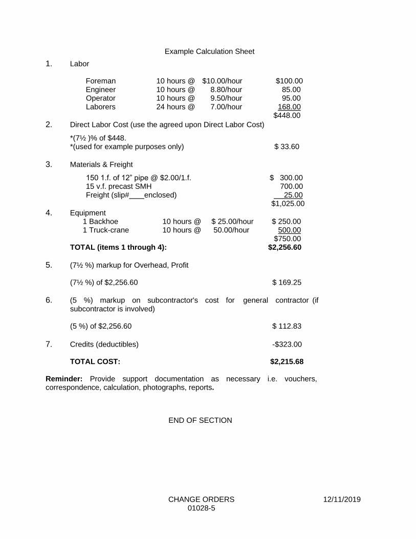
CHANGE ORDERS 12/11/2019 01028-5
Example Calculation Sheet
1. Labor Foreman 10 hours @ $10.00/hour $100.00 Engineer 10 hours @ 8.80/hour 85.00 Operator 10 hours @ 9.50/hour 95.00 Laborers 24 hours @ 7.00/hour 168.00
$448.00
2. Direct Labor Cost (use the agreed upon Direct Labor Cost)
*(7½ )% of $448. *(used for example purposes only) $ 33.60
3. Materials & Freight
150 1.f. of 12” pipe @ $2.00/1.f. $ 300.00 15 v.f. precast SMH 700.00 Freight (slip# enclosed) 25.00
$1,025.00
4. Equipment 1 Backhoe 10 hours @ $ 25.00/hour $ 250.00 1 Truck-crane 10 hours @ 50.00/hour 500.00
$750.00 TOTAL (items 1 through 4): $2,256.60
5. (7½ %) markup for Overhead, Profit
(7½ %) of $2,256.60 $ 169.25
6. (5 %) markup on subcontractor's cost for general contractor (if subcontractor is involved)
(5 %) of $2,256.60 $ 112.83
7. Credits (deductibles) -$323.00
TOTAL COST: $2,215.68 Reminder: Provide support documentation as necessary i.e. vouchers, correspondence, calculation, photographs, reports.
END OF SECTION
FIELD ENGINEERING 12/8/2017 01050-1
SECTION 01050
FIELD ENGINEERING
PART 1 GENERAL
1.01 DESCRIPTION
A. Work included: Provide such field engineering services as are required for
proper completion of the work including, but not necessarily limited to:
1. Establishing and maintaining lines and levels. 2. Layout of new water main.
3. Structural design of shores, forms and similar items provided by the
Contractor as part of his means and methods of construction.
1.02 RELATED WORK
A. Documents affecting work of this section include, but are not necessarily
limited to, General Conditions, Supplementary Conditions, and Sections in
Division 1 of these Specifications.
B. Additional requirements for field engineering may also be described in other
Sections of these Specifications.
1.03 QUALITY ASSURANCE
A. Use adequate numbers of skilled workmen who are thoroughly trained and
experienced in the necessary crafts and who are completely familiar with the
specified requirements and the methods needed for the proper performance
of the work of this Section.
B. Unless otherwise permitted by the Engineer, the layout for the water main shall be
performed using an electronic instrument (total station) by personnel under the
direction of a land surveyor or professional engineer licensed in the state where
work is being performed under this contract.
FIELD ENGINEERING 12/8/2017 01050-2
1.04 PROCEDURES
A. In addition to procedures directed by the Contractor for proper performance
of the Contractor's responsibilities:
1. Locate and protect control points before starting work on the site.
2. Preserve permanent reference points during progress of the work.
3. Verification of all reference points. a. If a discrepancy is found, promptly notify the Engineer.
4. Promptly advise the Engineer when a reference point is lost or
destroyed, or requires relocation because of other changes in the
Work.
a. Upon direction of the Engineer, require the Field Engineer
to replace reference stakes or markers.
b. Locate such replacements according to the original survey control.
1.05 SURVEY REQUIREMENTS
A. In projects where elevation work is critical, the Contractor shall establish a
minimum of two permanent benchmarks on site; referenced to data
established by survey control points.
B. Contractor to establish and maintain control lines and levels. Locate and lay out by instrumentation and similar appropriate means: 1. Accurate field layout of the new water main including, but not necessarily
limited to the locations of the following in accordance with the Contract
Drawings and Detailed Specifications: • Centerline of pipe (a minimum of every 200 LF)
• Valves
• Horizontal and vertical elbows
• Reducers
• Connections to existing water mains
• Hydrants
• PC, PT and PI of curved alignments.
2. Site improvements, including pavements, stakes for grading, fill and
topsoil placement, utility locations, slopes, and invert elevations. 3. Grid or axis for structures.
PART 2 PRODUCTS (Not Applicable) PART 3 EXECUTION (Not Applicable)
END OF SECTION

ABBREVIATIONS & DEFINITIONS 12/2/2020 01092-1
SECTION 01092
ABBREVIATIONS & DEFINITIONS
PART 1 GENERAL
1.01 DESCRIPTION
A. Listing of Abbreviations: The listing of abbreviations in this Specification
Section represent the Standard Organization named.
B. Related Work
1. Documents affecting work of this section include, but are not necessarily limited to Sections in Division 1 of these Specifications.
2. All related Specification Sections shall be used in conjunction with this Section.
1.02 QUALITY ASSURANCE
A. For products or workmanship specified by association, trade, or Federal
Standards, comply with requirements of the Standard, except when more stringent requirements are specified or are required by applicable codes.
B. Conform to reference standard by date of issue current on date for receiving
bids.
1.03 LISTING OF STANDARD ORGANIZATIONS AND THEIR ABBREVIATIONS
AA Aluminum Association AAN American Association of Nurserymen AASHTO American Association of State Highway and Transportation Officials ACI American Concrete Institute ACPA American Concrete Pipe Institute ADC Air Diffusion Council AGA American Gas Association AGCA Associated General Contractors of America AHDGA American Hot Dip Galvanizers Association AI Asphalt Institute AIA American Institute of Architects AISC American Institute of Steel Constructors AISI American Iron and Steel Institute ANSI American National Standards Institute APA American Plywood Association API American Petroleum Institute ASCE American Society of Civil Engineers ASHRAE American Society of Heating, Refrigerating, and Air Conditioning Engineers ASME American Society of Mechanical Engineers ASTM American Society of Testing and Materials AWC Aquarion Water Company

ABBREVIATIONS & DEFINITIONS 12/2/2020 01092-2
AWPA American Wood Preservers Association AWS American Welding Society AWWA American Water Works Association BIA Brick Institute of America CRSI Concrete Reinforcing Steel Institute CSA Canadian Standards Association DHI Door and Hardware Institute DIPRA Ductile Iron Pipe Research Association EJCDC Engineers Joint Contract Documents Committee EPA Environmental Protection Agency FM Factory Mutual Fed. Spec. Federal Specification HI Hydraulic Institute IEEE Institute of Electrical and Electronics Engineers ISA Instrument Society of America ISO International Standards Organization MIA Masonry Institute of America MIL. Military Specification MSS Manufacturers Standardization Society of the Valve and Fitting Industry NAAMM National Association of Architectural Metal Manufacturers NCMA National Concrete Masonry Association NEC National Electrical Code NEMA National Electrical Manufacturers Association NFPA National Fire Protection Association NRCA National Roofing Contractors Association NSPC National Standard Plumbing Code OSHA Occupational Safety and Health Administration PCA Portland Cement Association PCI Prestressed Concrete Institute PPI Plastic Pipe Institute PS Product Standards of the National Bureau of Standards SDI Steel Door Institute SIGMA Sealed Insulating Glass Manufacturers Association SMACNA Sheet Metal and Air Conditioning Contractors National Association SPI Society of the Plastics Industry SSPC Steel Structures Painting Council TCA Tile Council of America TPI Truss Plate Institute UL Underwriters Laboratories
ABBREVIATIONS & DEFINITIONS 12/2/2020 01092-3
1.04 DEFINITIONS
A. Contractor - The person, firm or corporation working on infrastructure to be owned and/or maintained by the Aquarion Water Company (AWC).
B. "Directed", "Permitted", "Required", or words of like effect, shall mean that the
direction, permission or the requirements of the AWC is intended. The words "approved", "acceptable", "satisfactory", or word of like import, shall mean approved, acceptable or satisfactory to the AWC.
Where indicated in these specifications that the Contractor is "required" or
"directed" by the AWC, or in words of like import, to perform some action, provide some material or equipment or provide information, the cost of such actions or provisions shall be borne by the Contractor and paid for as part of the prices bid, unless otherwise specifically provided for in these specifications.
C. Drawings - The part of the approved project showing the characteristics and
scope of the work to be performed and which have been prepared or approved by the AWC. The term "Drawings" is used interchangeably with the terms "Plans" and "Plates.".
E. Engineer - The person, firm or corporation named as a consultant by the AWC.
F. Final Completion - That date as certified by the Engineer when all work on the
entire project has been fully completed, including all work on the punch list, with the possible exception of final paving.
G. Owner - A public or quasi-public body or authority, corporation, association,
partnership, or individual for whom the Work is to be performed. The Aquarion Water Company will act as Owner.
H. Plans - The approved Drawings, or exact reproductions thereof, which show
the scope, character, dimensions and details of the work and which have been prepared by the Contractor's Engineer.
I. Project - The undertaking to be performed as provided in the Contract
Documents.
J. Resident Observer or Project Representative - The authorized representative
of the AWC who is assigned to the Project or any part thereof.
K. Shall - Must, obligation to complete the specified task or directive.
L. Shop Drawings - All drawings, diagrams, illustrations, brochures, schedules
and other data which are prepared by the Contractor, a Subcontractor, manufacturer, supplier or distributor, which illustrate how specific portions of the work shall be fabricated or installed.

ABBREVIATIONS & DEFINITIONS 12/2/2020 01092-4
M. Specifications - A part of the Technical Specifications consisting of written descriptions of a technical nature of materials, equipment, construction systems, standards and workmanship.
M. Special Conditions - Revisions or additions to the Conditions or Specifications
applicable to an individual Project.
N. Subcontractor - An individual, firm or corporation having a direct Contract with
Contractor or with any other Subcontractor for the performance of a part of the Work at the site.
O. Substantial Completion - That date as certified by the Owner when the
construction of the Project or a specified part thereof, is sufficiently completed, in accordance with the Technical Specifications, so that the Project or specified part can be utilized for the purposes for which it is intended.
P. Supplier - Any person or organization who supplies materials or equipment for
the Work, including that fabricated to a special design, but who does not perform labor at the site.
Q. Surety - The Corporate Body which is bound with and for the Contractor, and which engages to be responsible for his payment of all debts pertaining to, and for his acceptable performance of the Work for which he has contracted, as more particularly set forth in the Performance Payment Bond.
R. Work - All labor necessary to produce the construction required by the
approved Drawings and Technical Specifications, and all materials and equipment incorporated or to be incorporated in the Project.
S. Work on (at) the Project - Work to be performed at the Project, including the
transportation of materials and supplies to or from the location of the Project by employees of the Contractor and any Subcontractor.
T. Written Notice - Any notice to any party of the Agreement relative to any part of
his Agreement in writing and considered delivered and the service thereof completed, when posted by certified or registered mail to the said party at his last given address, or delivered in person to said party or his authorized representative on the Work.
PART 2 PRODUCTS (Not Applicable)
PART 3 EXECUTION (Not Applicable)
END OF SECTION

SPECIAL PROVISIONS 12/11/2019 01140-1
SECTION 01140
SPECIAL PROVISIONS
PART 1 GENERAL
1.01 DESCRIPTION
A. The work of this section consists of special provisions during construction
including:
1. Water for Construction Purposes
2. Occupying Private Property
3. Existing Utility Locations
4. Coordination of Work
5. Time For Completion of Contract
6. Maintenance of Trench Surface
7. Compliance With Permits
8. Connections to Existing Water Systems
9. Protection of Aquifers
10. Contractor’s Representative PART 2 PRODUCTS (Not Applicable)
PART 3 EXECUTION
3.01 WATER FOR CONSTRUCTION PURPOSES
A. In locations where water is in sufficient supply, the Contractor may be allowed to
use water without charge for construction purposes. The express approval of the
Owner shall be obtained before water is used. Waste of water by the Contractor
shall be sufficient cause for withdrawing the privilege of unrestricted use. The
Contractor shall coordinate with the owner to obtain a meter and backflow device
(hydrant rig). The meter and backflow device shall be installed at the location
directed by the Owner. If directed by the Owner, the Contractor shall provide at no
charge a backflow preventer and meter for use. All materials must meet the
requirements of the Owner.
3.02 OCCUPYING PRIVATE PROPERTY
A. The Contractor shall not enter upon nor occupy with men, equipment or materials
and property outside of the public highways or Owner’s easements, except with
the written consent of the property owner or property owner’s agent.
SPECIAL PROVISIONS 12/11/2019 01140-2
3.03 EXISTING UTILITY LOCATIONS – CONTRACTOR’S RESPONSIBILITY
A. The Contractor shall coordinate all work involving utilities and shall satisfy himself
as to the existing conditions of the areas in which he is to perform his work. He shall conduct and arrange his work so as not to impede or interfere with the work of other contractors working in the same or adjacent areas.
3.04 COORDINATION OF WORK
A. The General Contractor shall be responsible for coordinating his own work as well
as that of any subcontractors. He shall be responsible for notification of the
Engineer when each phase of work is expected to begin and the approximate completion date.
3.05 TIME FOR COMPLETION OF CONTRACT
A. The time for completion of the contract is stipulated in the Form of General Bid.
The Bidder shall base his bid on completing the proposed work by the completion date stipulated in Section 00650 Notice To Proceed.
3.06 MAINTENANCE OF TRENCH SURFACE
A. After backfilling and compacting the trench, the Contractor shall be responsible for
keeping the ground surface dry and passable at all times until the surface has been restored to original condition.
3.07 COMPLIANCE WITH PERMITS
A. The Contractor shall perform all work in conformance with the requirements of permits
required by the jurisdiction in which the work under this contract is to take place.
3.08 CONNECTIONS TO EXISTING WATER SYSTEMS
A. The Contractor shall provide the Owner a minimum five (5) days notice in advance of
performing work requiring operation of valves. The Owner will schedule field personnel
to assist the Contractor by locating and operating valves required for draining or admitting
water to the various sections of the water mains as required to perform the proposed
work. The Contractor shall not have any grounds for claims due to scheduling conflicts
with the Owner’s personnel. No damages shall be claimed by the Contractor for delays
in dewatering pipelines nor shall any damages be claimed because of water leaking
through closed valves after dewatering is completed.
B. Connections to the existing distribution system shall be made with the mains under
pressure unless the lines can be temporarily taken out of service as approved by the
Owner
C. The Contractor will be required to make test excavations to ascertain that the proposed
position of the connections will be clear of joints, fittings, or other obstructions.
SPECIAL PROVISIONS 12/11/2019 01140-3
D. If any failure occurs in connection to existing mains, service shall be restored in the
shortest possible time, the Contractor working around the clock, if necessary. He shall
cooperate with the Owner in notifying the customers or supplying emergency water. If
required by the Owner, the Contractor shall make connections to the water mains during
night hours, on Sunday or at other times of off-peak demand of water.
3.09 PORTECTION OF AQUIFER
A. The Contractor’s attention is directed to the fact that the construction area may be located
within a water supply watershed. The Contractor shall take extra precautions to ensure
that no pollutants enter the groundwater table from the construction area. The Contractor
shall not store fuels or other hazardous materials or potential contaminants on the
construction site. In the event of a spill, the Contractor shall immediately notify the Owner
and Engineer.
3.10 CONTRACTOR’S REPRESENTATIVE
A. The Contractor shall designate a representative who will be available to respond to
emergency calls by the Owner at any time; day, night, on weekends and holidays should
such a situation arise.
END OF SECTION

PROJECT MEETINGS 3/17/2017 01200-1
SECTION 01200
PROJECT MEETINGS PART 1 - GENERAL 1.01 DESCRIPTION
A. This Section specifies requirements for project meetings including but not limited
to Pre-Construction Conference and Progress Meetings. B. It shall be the responsibility of the Contractor to coordinate work between all
subcontractors, sections, and trades required for the proper completion of the Work.
1.02 PRE-CONSTRUCTION CONFERENCE
A. After the bids have been opened but prior to the start of the construction there will be a pre-construction conference to discuss the phasing and scheduling of the Project. The specific time and place of the conference shall be arranged by the Engineer after the Contract has been awarded.
B. This pre-construction conference is intended to establish lines of communication
between the parties involved, review responsibilities and personnel assignments, establish project schedules, discuss proposed performance methods, and coordinate Work to be performed by subcontractors.
C. Authorized representatives of the Owner, Engineer and their consultants, the
Contractor, its Superintendent and Site Foreman, and all others invited by the Contractor, shall attend the pre-construction conference. All participants at the conference shall be familiar with the Project and authorized to conclude matters relating to the Work.
D. Discuss items of significance at the pre-construction conference that could affect
progress including at least the following:
1. Tentative construction schedule 2. Critical Work sequencing 3. Designation of responsible personnel 4. Procedures for processing field decisions and Change Orders 5. Procedures for processing Applications for Payment 6. Review of Davis Bacon and other federal requirements 7. Distribution of Contract Documents 8. Submittal of Shop Drawings, Product Data and Samples 9. Preparation of record documents 10. Use of the premises 11. Office, work and storage, and laydown areas 12. Equipment deliveries 13. Construction safety procedures 14. Environmental health and safety procedures
PROJECT MEETINGS 3/17/2017 01200-2
15. First aid 16. Security 17. Housekeeping 18. Working hours 19. Traffic Control 20. Emergency Vehicle Access to and around work site 21. Environmental protection measures for construction site
1.03 PROGRESS MEETINGS
A. During the course of the Project, the Contractor shall attend weekly progress meetings as scheduled by the Owner. The Owner, based on work progress and activities, may adjust the progress meetings to twice per month or other. The attendance of subcontractors may be required during the progress of the Work. The Contractor's delegate to the meeting shall be prepared and authorized to discuss the following items:
1. Progress of Work/Critical Work Sequencing in relation to Contract
Schedule. 2. Proposed Work activities for forthcoming period. 3. Resources committed to Contract. 4. Coordination of Work with others. 5. Status of procurement of equipment and materials. 6. Status of Submittals. 7. Outstanding actions, decisions, or approvals that affect Work activities.
8. Site access and/or security issues 9. Hazards and risks 10. Housekeeping 11. Quality issues
12. Potential Claims 13. Change Orders 14. Costs, budget, and payment requests
B. The Contractor shall revise the construction schedule after each progress meeting where revisions to the schedule have been made or recognized and the revised schedule shall be submitted to the Engineer and Owner.
PART 2 - PRODUCTS Not used. PART 3 – EXECUTION Not used.
END OF SECTION
SUBMITTALS 3/17/2017 01300-1
SECTION 01300 SUBMITTALS PART 1 - GENERAL 1.01 WORK INCLUDED A. The Contractor shall provide the Engineer with submittals as required by the
contract documents. 1.02 RELATED WORK A. Divisions 1 – 16 of these specifications that require submittals. PART 2 - PRODUCTS NOT USED PART 3 - EXECUTION 3.01 GENERAL A. As required by the General Conditions, Contractor shall submit a schedule of shop
and working drawing submittals. B. The Contractor shall submit the shop and working drawing submittals either
electronically or hard copy. 3.02 ELECTRONIC SUBMITTALS
A. In accordance with the accepted schedule, the Contractor shall submit promptly to the Engineer by email, one electronic copy in Portable Document Format (PDF) of shop or working drawings required as noted in the specifications, of equipment, structural details and materials fabricated especially for this Contract.
B. Each electronic copy of the shop or working drawing shall be accompanied by the
Engineer’s standard shop drawing transmittal form, included as Exhibit 1 of this section (use only for electronic submittals), on which is a list of the drawings, descriptions and numbers and the names of the Owner, Project, Contractor and building, equipment or structure. A fillable PDF version of this form will be provided by the Owner for completion. Submittals and submittal cover sheets shall be legibly written, with preference to type written work. Any cover sheets or submittals determined to illegible will be rejected without review.
C. The Contractor shall receive a shop drawing memorandum with the Engineer’s
approval or comments via email.
SUBMITTALS 3/17/2017 01300-2
3.03 HARD COPY SUBMITTALS
A. In general, the Engineer will accept and prefer electronic copies of the submittals. However if requested by the Engineer, the Contractor shall submit promptly to the Engineer, by mail the Engineer’s Office, six (6) copies each of shop or working drawings required as noted in the specifications, of equipment, structural details and materials fabricated especially for this Contract.
B. Each shipment of drawings shall be accompanied by the Engineer’s (if applicable)
standard shop drawing transmittal form on which is a list of the drawings, descriptions and numbers and the names of the Owner, Project, Contractor and building, equipment or structure.
3.04 SHOP AND WORKING DRAWINGS A. Shop and working drawings shall show the principal dimensions, weight, structural
and operating features, space required, clearances, type and/or brand of finish of shop coat, grease fittings, etc., depending on the subject of the drawings. When it is customary to do so, when the dimensions are of particular importance, or when so specified, the drawings shall be certified by the manufacturer or fabricator as correct for this Contract.
B. All shop and working drawings shall be submitted to the Engineer by and/or through
the Contractor, who shall be responsible for obtaining shop and working drawings from his subcontractors and returning reviewed drawings to them. All shop and working drawings shall be prepared on standard size, 24-inch by 36-inch sheets, except those, which are made by changing existing standard shop or working drawings. All drawings shall be clearly marked with the names of the Owner, Project, Contractor and building, equipment or structure to which the drawing applies, and shall be suitably numbered. Each shipment of drawings shall be accompanied by the Engineer’s (if applicable) standard shop drawing transmittal form on which is a list of the drawings, descriptions and numbers and the names mentioned above.
C. Only drawings that have been prepared, checked and corrected by the fabricator
should be submitted to the Contractor by his subcontractors and vendors. Prior to submitting drawings to the Engineer, the Contractor shall check thoroughly all such drawings to satisfy himself that the subject matter thereof conforms to the Contract Documents in all respects. Shop drawings shall be reviewed and marked with the date, checker's name and indication of the Contractor's approval, and only then shall be submitted to the Engineer. Shop drawings unsatisfactory to the Contractor shall be returned directly to their source for correction, without submittal to the Engineer. Shop drawings submitted to the Engineer without the Contractor's approval stamp and signature will be rejected. Any deviation from the Contract Documents indicated on the shop drawings must be identified on the drawings and in a separate submittal to the Engineer, as required under subsection 6.17 Shop Drawings and Samples; C. Submittal Procedures, Paragraph 3 of the General Conditions.
D. The Contractor shall be responsible for the prompt submittal and resubmittal, as
necessary, of all shop and working drawings so that there will be no delay in the work due to the absence of such drawings.
SUBMITTALS 3/17/2017 01300-3
E. The Engineer will review the shop and working drawings as to their general conformance with the design concept of the project and general compliance with the information given in the Contract Documents. Corrections of comments made on the drawings during the review do not relieve the Contractor from compliance with requirements of the Contract Documents. The Contractor is responsible for: confirming and correlating all quantities and dimensions; selecting fabrication processes and techniques of construction; coordinating his work with that of all other trades; and performing his work in a safe and satisfactory manner. The review of the shop drawings is general and shall not relieve the Contractor of the responsibility for details of design, dimensions, code compliance, etc., necessary for interfacing with other components, proper fitting and construction of the work required by the Contract and for achieving the specified performance. The Engineer will review submittals two times: once upon original submission and a second time if the Engineer requires a revision or corrections. The Contractor shall reimburse the Owner amounts charged to the Owner by the Engineer for performing any review of a submittal for the third time or greater.
F. With few exceptions, shop drawings will be reviewed and returned to the Contractor
within 30 days of submittal. G. No material or equipment shall be purchased or fabricated especially for this
Contract nor shall the Contractor proceed with any portion of the work, the design and details of which are dependent upon the design and details of equipment or other features for which review is required, until the required shop and working drawings have been submitted and reviewed by the Engineer as to their general conformance and compliance with the project and its Contract Documents. All materials and work involved in the construction shall then be as represented by said drawings.
H. Two copies of the shop and working drawings and/or catalog cuts will be returned to
the Contractor. The Contractor shall furnish additional copies of such drawings or catalog cuts when he needs more than two copies or when so requested.
3.05 SAMPLES A. Samples specified in individual Sections include, but are not necessarily limited to,
physical examples of the work such as sections of manufactured or fabricated work, small cuts or containers of materials, complete units of repetitively-used products, color/texture/pattern swatches and range sets, specimens for coordination of visual effect, graphic symbols, and units of work to be used by the Engineer or Owner for independent inspection and testing, as applicable to the work.
B. The number of samples submitted shall be as specified. Submittal and processing of
samples shall follow the procedures outlined for shop and working drawings unless the specifications call for a field submittal or mock-up.
C. Acceptance of samples will be acknowledged via a copy of the transmittal noting
status. When samples are not acceptable, prompt resubmittal will be required. END OF SECTION
SUBMITTALS 3/17/2017 01300-4
EXHIBIT 1 TO SECTION 01330 SUBMITTALS
SHOP DRAWING TRANSMITTAL FORM
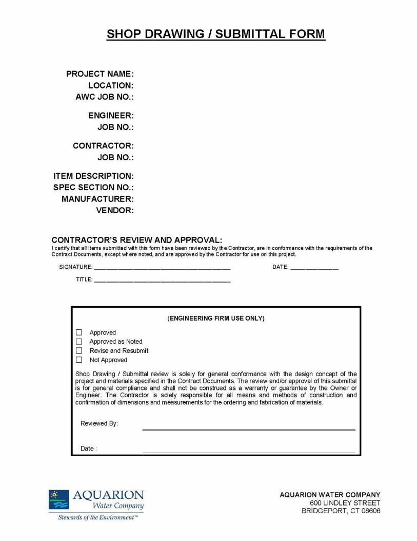
SUBMITTALS 3/17/2017 01300-5

CONSTRUCTION SCHEDULES 3/17/2017 01310-1
SECTION 01310
CONSTRUCTION SCHEDULES
PART 1 GENERAL
1.01 SUMMARY
A. To assure adequate planning and execution of the work so that the Work is
completed within the number of calendar days allowed in the Contract, and to
assist the Engineer in appraising the reasonableness of the proposed schedule
and in evaluating progress of the Work, prepare and maintain the schedules and reports described in this Section.
1.02 RELATED WORK
A. Documents affecting the work of this Section include, but are not necessarily
limited to, General Conditions, Supplementary Conditions, and Sections in
Division 1 of these Specifications. 1. Construction period: Contract Agreement
B. Definitions:
1. "Day", as used throughout the Contract unless otherwise stated, means
"calendar day".
1.03 QUALITY ASSURANCE
A. Employ a scheduler who is thoroughly trained and experienced in compiling
construction schedule data and in preparing and issuing periodic reports as required by this Specification.
B. Perform data preparation, analysis, charting and updating in accordance with
standards approved by the Engineer.
C. Reliance upon the approved schedule:
1. The construction schedule as approved by the Engineer shall be an
integral part of the Contract and shall establish interim completion dates
for the various activities under the Contract.
2. Should any activity not be completed within 15 days after the stated
scheduled date, the Engineer may request the reason for the delay in
schedule from the Contractor. The Contractor shall supply the requested information and the steps which he intends to take to get back on schedule.
3. It is expressly understood and agreed that failure by the Engineer to
exercise the option either to order the Contractor to expedite an activity or
to expedite the activity by other means shall not be considered to set a
precedent for any other activities.

CONSTRUCTION SCHEDULES 3/17/2017 01310-2
1.04 SUBMITTALS
A. Comply with pertinent provisions of Section 01300.
B. Preliminary Analysis: Within ten (10) calendar days after the Contractor has
received the Owner's Notice to Proceed, submit four (4) prints of a preliminary
construction schedule to Owner and Engineer.
C. Construction Schedule: Within thirty (30) calendar days after the Contractor has
received the Owner's Notice to Proceed submit a Critical Path Method (CPM)
network and a computer generated print out of a construction schedule prepared
in accordance with Part 2 of this Section to Owner and Engineer.
D. Cash Flow Projection Summary: The Contractor shall submit an updated Cash
Flow Projection Summary showing the breakdown of cash flows for the project
with each Application for Payment. Applications for Payment will not be processed
without an updated Cash Flow Projection Summary.
D. Periodic Reports: See paragraph 2.02-B of this Section.
PART 2 PRODUCTS
2.01 CONSTRUCTION ANALYSIS
A. The Contractor shall provide a detailed work schedule, projected at least a month
in advance. The implementation of the work schedule and the coordination
required shall constitute the basic agenda of the coordination and planning
meetings.
B. The order of new construction shall be discussed with the Engineer well in
advance of the contemplated construction and the intended schedule shall meet
with his approval. The Contractor, prior to starting work, shall submit to the
Engineer a written description of the methods he plans to use in doing the work,
including any necessary plans depicting the proposed details as well as a schedule
of expected dates for beginning and completing the various buildings, structures
and appurtenances which make up the work. Work shall not commence on a given
portion of the project until the schedule for that portion (and preferably the entire
schedule) has been approved by the Engineer. The Contractor shall be required
to update this schedule periodically as necessary.
2.02 CONTRACTOR'S CONSTRUCTION SCHEDULE
A. This schedule shall include a Critical Path Network and a computer generated print
out. The schedule shall account for all subcontracts in addition to the work of the
Contractor.
CONSTRUCTION SCHEDULES 3/17/2017 01310-3
B. The network shall be provided in the form of a time scaled schedule. The computer
printout shall include as a minimum, the earliest starting, earliest finish, latest
starting, latest finish dates, and the total float for each activity. The Contractor
shall update (monitor) and run the schedule at least monthly and shall submit to
the Engineer both the network and computer printout, both in duplicate, at the
same time the pay estimate is prepared. The schedule shall contain all of the
items of the periodic estimate and pay schedule.
PART 3 EXECUTION
3.01 SCHEDULE AND UPDATES
A. The monthly schedule update (monitoring) shall include the following items.
1. Network: Activities that are completed or in process are to be identified on
the network by contrasting heavy lines. Each activity and work done should be proportional to the percentage of progress achieved to date.
2. Computer printout: The percentage progress status of each activity shall
be shown on the computer printout. The percentage progress status will be used to support the Contractor's periodic pay estimate. Actual start and
completion dates are to be included in the computer printout. All activities started and in process should be flagged in the computer printout.
3. The Engineer reserves the right to modify any schedule as required to
meet the prevailing conditions. Review of the work schedules by the Engineer shall not relieve the Contractor of responsibilities regarding
specified project completion times and liquidated damages. 4. Along with the Application for Payment and updated schedule, the
Contractor shall submit an updated Cash Flow Projection Summary.
END OF SECTION
HEALTH AND SAFETY PLAN 01350-1 3/17/2017
SECTION 01350
HEALTH & SAFETY PLAN
PART 1 GENERAL
1.01 SUMMARY
A. The work of this section consists of:
1. Furnish all labor, equipment and materials and perform all operations in connection with monitoring air quality, decontaminating equipment and providing worker health and safety protection for all Contractor personnel.
2. Develop a site specific Health and Safety Plan (HASP) specifically addressing the potential hazards that may be encountered. This plan shall meet all OSHA and Owner Contractor Safety Manual requirements. The plan shall be submitted at the time the contract is awarded.
3. Review the requirements and data presented and supplement the program with any additional measures deemed necessary to fully comply with regulatory requirements and adequately protect personnel on the site.
4. The Health and Safety Plan shall be kept onsite throughout the course of the work, for verification that the Contractor is performing in accordance with the plan.
1.02 REFERENCES
A. OSHA Regulation 29 CFR 1910.120
1.03 DEFINITIONS
A. Site Safety Official (SSO) - The individual who is responsible to the Contractor and has the authority and knowledge necessary to implement the site safety and health plan and verify compliance with applicable safety and health requirements.
1.04 SUBMITTALS
A. Informational Submittals
1. Submit the following within seven (7) days after the Notice of Award.
a. Site-specific HASP including the Emergency Response Plan for review, including provisions for decontamination and a contingency plan for unforeseen emergencies. The Engineer’s review is only to determine if the HASP meets basic regulatory requirements and the minimum requirements of this section. The
HEALTH AND SAFETY PLAN 01350-2 3/17/2017
review will not determine the adequacy of the HASP to address all potential hazards, as that remains the sole responsibility of the Contractor.
b. Current certification of employee's health and safety training and certification of employee's baseline medical exam status.
c. Certification of additional required health and safety training for supervisors.
d. Qualifications and experience of the SSO for approval.
2. Submit minutes of weekly safety meetings at periodic progress meetings.
1.05 CONTRACTOR’S RESPONSIBILITIES
A. The Contractor is solely responsible for the health and safety of workers employed by the Contractor, any subcontractor and anyone directly or indirectly employed by any of them.
B. Work under this contract is not being performed on an “Uncontrolled Hazardous Waste Site,” as defined in 29 CFR 1910.120. Develop and follow a site specific Health & Safety Plan (HASP) in accordance with the requirements of 29 CFR 1910.120 and paragraph 1.6.
C. Establish emergency routes of travel.
D. Train all workers assigned to areas where contaminated media are likely to be encountered in accordance with 29 CFR 1910.120.
E. In areas where contaminated media are likely to be encountered, monitor air quality in and around work area using appropriate air monitoring equipment, as indicated in Part 2. Record all readings and maintain record on site. Stop work and/or upgrade respiratory protection or personal protective equipment levels if action levels established in the HASP are exceeded. Ensure that degree and type of respiratory protection provided is consistent with the monitored concentrations and individual chemical parameters. Lawfully dispose of all contaminated clothing and equipment that cannot be decontaminated.
F. At all times, prevent oil or other hazardous substances from entering the ground, sewers, drainage areas and piping systems.
1.06 HEALTH & SAFETY PLAN (HASP) REQUIREMENTS
A. The following items shall be addressed in the HASP:
1. Contractors Safety Manual requirements;
2. safety and health hazard assessment;
HEALTH AND SAFETY PLAN 01350-3 3/17/2017
3. procedures for emergency medical treatment and first aid;
4. map indicating route to hospital for emergency medical care;
5. equipment decontamination procedures;
6. chemical hazards (including hydrofluosilicic acid);
7. air monitoring procedures and action levels;
8. personal protective equipment and decontamination;
9. physical hazard evaluation and abatement including:
a. equipment operation;
b. confined space entry;
c. slips and falls;
d. building collapse;
e. falling debris;
f. encountering unmarked utilities;
g. cold and heat stress;
h. hot work (cutting and welding);
i. excavation entry;
10. training requirements;
11. recordkeeping requirements;
12. emergency response plan that includes:
a. names of three (3) Emergency Response Contractors, experienced in the removal and disposal of oils and hazardous chemicals, that the Contractor intends to use in the event of an emergency;
b. evacuation routes and procedures;
c. emergency alerting and response procedures.
1.07 CONTINGENCY MEASURES & NOTIFICATIONS
A. In the event that potentially hazardous materials are encountered during the work under this contract, the responsibilities of the Contractor and the Engineer are described herein.
HEALTH AND SAFETY PLAN 01350-4 3/17/2017
B. The procedures and protocols to be used by the SSO in defining materials that are potentially hazardous include screening with a photo-ionization detector, odor, visual appearance of a material, pH testing for acidic materials, and obvious oil or chemical contaminated materials.
C. Upon encountering suspected hazardous buried objects or materials as described above, cover the excavation immediately if no imminent danger, as defined by the SSO, is present. If there is an imminent danger, as defined by the SSO, Evacuate the area immediately. The SSO shall then notify the Engineer and the Owner of the situation.
D. Establish, properly barricade, and mark the area as an exclusion zone under the direction of the SSO. The SSO shall establish the exclusion zone boundaries based upon air quality monitoring using a photo-ionization detector and other equipment as appropriate. The exclusion zone shall be established at a minimum 50-foot radius around the location where the potentially hazardous material is encountered. Work within the exclusion zone shall be discontinued until the hazardous condition has been remediated and testing indicates that a hazard does not exist. Other activities of the site, outside the limits of the exclusion zone shall continue. Ambient air quality monitoring shall be performed by the SSO to demonstrate that ambient air quality in other portions of the site is not adversely impacted by the exclusion zone condition.
E. Notify the Engineer and the Owner regarding the presence of potentially hazardous materials. The Owner may direct the Contractor to notify regulators and to obtain necessary regulatory approvals for remediation.
F. Mobilize the appropriate equipment and personnel to sample and test the hazardous material within the exclusion zone to determine the remedial action required, subject to the Engineer’s direction. The Contractor may be directed to remove and legally dispose of the material. Compensation for the removal and disposal of hazardous material will be as a Change in Work and Change in Contract Price in accordance with the General Conditions, if not covered under a specific bid item.
PART 2 PRODUCTS
NOT USED
PART 3 EXECUTION
NOT USED
END OF SECTION

PRE-CONSTRUCTION VIDEO RECORDING 3/1/2017 01385-1
SECTION 01385
PRE-CONSTRUCTION VIDEO RECORDING
PART 1 GENERAL
1.01 DESCRIPTION
A. Work included: The Contractor shall provide all labor, materials, tools and
equipment necessary to furnish a video recording of the site prior to the start of the work.
1.02 RELATED WORK
A. Documents affecting the work of this Section include, but are not necessarily
limited to, General Conditions, Supplementary Conditions, and all Divisions of these Specifications.
1.03 QUALITY ASSURANCE
A. Use adequate numbers of skilled workmen who are thoroughly trained and
experienced in the necessary crafts and who are completely familiar with the specified requirements and the methods needed for proper performance of the work of this Section.
PART 2 PRODUCTS (Not Applicable)
PART 3 EXECUTION 3.01 VIDEO RECORDING
A. Equipment
1. The equipment employed in the video recording shall be sufficient to provide a clear, full color and detailed visual description of the site along with a detailed narrative description of physical conditions and location.
B. Area Included
1. The area included in the video recording shall include the actual location of the work, the adjacent property and all other areas which could reasonably be anticipated to be affected by the work.
2. Particular attention should be paid to the existing condition of private property immediately adjacent to the work.

PRE-CONSTRUCTION VIDEO RECORDING 3/1/2017 01385-2
C. Documentation 1. The video recordings shall be conducted at a slow walking pace and
shall record the physical conditions in the area described above. 2. The narrative description shall be recorded simultaneously and shall
supplement the visual description particularly with regard to location. 3. Contractor shall furnish three (3) complete copies of the video recording
to the Engineer prior to the start of the work.
D. Personnel 1. All personnel employed by the Contractor in video recording shall be
experienced in all aspects of the process, including recognition of important physical conditions in and around the site of the Work.
END OF SECTION
TESTING LABORATORY SERVICES 12/8/2017 01410-1
SECTION 01410
TESTING LABORATORY SERVICES
PART 1 GENERAL
1.01 DESCRIPTION
A. Work Included: 1. Provide such testing and inspecting as are specified to be furnished by
the Contractor in this Section and/or elsewhere in the Contract
Documents. 2. Cooperate with any testing agency that may be independently selected
by Owner and all others responsible for testing and inspecting the Work.
B. Related Work:
1. Documents affecting work of this Section include, but are not necessarily
limited to, General Conditions, Supplementary Conditions, and Sections in Division 1 through Division 3 of these Specifications.
2. Requirements for testing are described in various Sections of these
Specifications. 3. Where no testing requirements are described, but the Owner decides
that testing is required, the Owner may require such testing to be
performed under current pertinent standards for testing.
1.02 QUALITY ASSURANCE
A. All testing laboratories will be submitted to Engineer for approval in accordance
with ASTM E329.
B. Testing, when required, will be in accordance with all pertinent codes and
regulations, and with selected standards of the American Society for Testing and
Materials.
C. When work is performed in the state right of way the nuclear density gauge used shall be certified within the same calendar year as the work is being performed.
1.03 PRODUCT HANDLING
A. Comply with pertinent provisions of Section 01610.
B. Promptly process and distribute required copies of test reports and related
instructions to assure necessary re-testing and replacement of materials with the
least possible delay in progress of the work.
TESTING LABORATORY SERVICES 12/8/2017 01410-2
PART 2 PRODUCTS 2.01 PAYMENT FOR TESTING
A. The Contractor shall pay for compaction testing of the backfilled material and be
reimbursed by the Owner within the allowance set out in the contract. If test results indicate work does not conform to specification requirements, the Contractor shall remove or correct the defective Work by re-compacting where appropriate, or by replacing as necessary and approved by the Engineer, to bring the work into compliance, at no additional cost to the Owner. Additional charges incurred due to the non-conforming test results shall be paid for by the Contractor and shall not be reimbursed by the Owner. All backfilled materials under structures and buildings shall be field tested for compliance with the requirements of this specification.
2.02 CODE COMPLIANCE TESTING
A. Inspections and tests required by codes or ordinances, or by a plan approval
authority, and by which are made by a legally constituted authority, shall be the responsibility of and shall be paid for by the Contractor.
2.03 CONTRACTOR'S CONVENIENCE TESTING
A. Inspecting and testing performed exclusively for the Contractor's convenience
shall be the sole responsibility of the Contractor. PART 3 EXECUTION
3.01 COOPERATION WITH TESTING LABORATORY
A. Representatives of the testing laboratory shall have access to the Work at all
times and at all locations where the Work is in progress. Provide facilities for such access to enable the laboratory to perform its functions properly.
3.02 TAKING SPECIMENS
A. All specimens and samples for testing, unless otherwise provided in the Contract
Documents, shall be taken by the testing personnel. All sampling equipment and personnel will be provided by the testing laboratory. All deliveries of specimens
and samples to the testing laboratory will be performed by the testing laboratory.

TESTING LABORATORY SERVICES 12/8/2017 01410-3
3.03 SCHEDULE FOR TESTING
A. Establishing schedule: By advance discussion with the testing laboratory
determine the time required for the laboratory to perform its test and to issue each of its findings. Submit schedule to Engineer for approval.
B. Revising schedule: When changes of construction schedule are necessary
during construction, coordinate all such changes with the testing laboratory as
required.
C. Adherence to schedule: When the testing laboratory is requested to test, but is
prevented from testing or taking specimens due to incompleteness of the work,
all extra charges for testing attributable to the delay may be back charged to the
Contractor.
END OF SECTION
MOBILIZATION 3/17/2017 01505-1
SECTION 01505
MOBILIZATION
PART 1 GENERAL
1.01 DESCRIPTION
A. Work Includes: The transportation and storage of all equipment and materials necessary to the Work and the field offices.
B. RELATED WORK
1. Documents affecting work of this Section include, but are not necessarily limited to, General Conditions, Supplementary Conditions, and Sections
in Division 1 through Division 3 of these Specifications.
PART 2 PRODUCTS (Not Applicable)
PART 3 EXECUTION
3.01 STORAGE AREA
A. It shall be the Contractor's sole responsibility to procure and maintain a suitable
storage area for tools, materials and equipment necessary to perform the work.
1. The storage area obtained by the Contractor shall not obstruct or interfere with pedestrian or vehicular movement, and shall not occupy any space
within the public right-of-way, except with specific permission from the Owner.
2. The Contractor shall provide to the Engineer and Owner copies of the written agreement stating the terms of the property rental with signatures from both the Contractor and property owner.
3. The storage area shall be kept neat at all times.
4. The Owner shall not be a party to negotiations related to acquisition of
areas for storage or cleanup of the same (unless the storage area is on Owner's property), but reserves the right to inspect such area(s) for
compliance with Town regulatory requirements.
5. Contractor shall not use storage area for bulk storage of hazardous materials (e.g., gasoline, solvents, oil).
3.02 EQUIPMENT
A. Contractor shall transport all equipment to the site, assemble the equipment as
needed to proceed with the work and maintain the equipment as needed during the work.
END OF SECTION

TEMPORARY FACILITIES 3/17/2017 01510-1
SECTION 01510
TEMPORARY FACILITIES
PART 1 GENERAL
1.01 DESCRIPTION
A. The work of this Section shall consist of providing the following temporary facilities:
1. Water 2. Sanitary Facilities
3. Drainage
PART 2 PRODUCTS
2.01 TEMPORARY WATER
A. Drinking water shall be provided by the Contractor for his personnel and the
personnel of his sub-contractors.
1. Drinking water shall be tested and approved by the State Agency as
"safe drinking water suitable for human consumption". 2. Contractor shall furnish water for construction.
2.02 TEMPORARY SANITARY FACILITIES
A. Sanitary conveniences, properly screened from public observation, for the use
of all persons employed on the work and beginning with the first man engaged in preliminary operations, shall be provided and maintained by the Contractor in
sufficient numbers through the completion of the work. 1. Contractor shall be diligent in maintaining sanitary facilities; pumping
weekly, or more often as required to protect soil and water quality.
2.03 TEMPORARY DRAINAGE
A. Temporary drainage, as necessary shall be provided by the Contractor to keep
the working area dry.
PART 3 EXECUTION (Not Applicable)
END OF SECTION
PROTECTION OF PROPERTY 3/17/2017
01545-1
SECTION 01545 PROTECTION OF PROPERTY PART 1 – GENERAL Not Used. PART 2 – PRODUCTS Not Used PART 3 - EXECUTION 3.01 HAULING, HANDLING AND STORAGE OF MATERIALS
A. The Contractor shall, at his own expense, handle and haul all materials furnished by him and shall remove any of his surplus materials at the completion of the work.
B. The Contractor shall provide suitable and adequate storage for equipment and
materials furnished by him that are liable to injury and shall be responsible for any loss of or damage to any equipment or materials by theft, breakage, or otherwise.
C. All excavated materials and equipment to be incorporated in the Work shall be placed
so as not to injure any part of the Work or existing facilities and so that free access can be had at all times to all parts of the Work and to all public utility installations in the vicinity of the work. Materials and equipment shall be kept neatly piled and compactly stored in such location as will cause a minimum of inconvenience to public travel and adjoining owners, tenants and occupants.
D. The Contractor shall be responsible for all damages to the work under construction
during its progress and until final completion and acceptance even though partial payments have been made under the Contract.
3.02 EASEMENTS A. As indicated on the drawings, the work is located in easements obtained by the
Owner. The Contractor has no rights outside of the easements unless they are obtained from the property owner.
B. Contractor shall schedule work so that it will cause minimum inconvenience and
nuisance to abutting property owners, over the shortest possible time. C. Easements shall be kept clean; no rubbish or discarded construction materials shall be
allowed to accumulate. Storage of excess construction materials, including soil, ledge, equipment, or machinery on easements will not be allowed.
D. Restoration of fences, shrubs, trees and grass shall be completed promptly following
completion of the work in an easement, to minimize disruption and inconvenience to property owners.
PROTECTION OF PROPERTY 3/17/2017
01545-2
E. Unless approved by the Engineer, the use of easements for ease of access to and
egress from other areas of the project will not be permitted. 3.03 OPEN EXCAVATIONS
A. All open excavations shall be adequately safeguarded by providing temporary barricades, caution signs, lights and other means to prevent accidents to persons, and damage to property. The Contractor shall, at his own expense, provide suitable and safe means for completely covering all open excavations and for accommodating travel when work is not in progress.
B. Bridges provided for access to private property during construction shall be removed
when no longer required. C. The length of open trench will be controlled by the particular surrounding conditions
but shall always be confined to the limits prescribed by the Engineer. D. If the excavation becomes a hazard, or if it excessively restricts traffic at any point,
then special construction procedures shall be taken, such as limiting the length of trench and prohibiting stocking excavated material in the street.
E. All street excavations shall be completely closed at the end of each work day.
Backfilling or use of steel plates of adequate strength to carry traffic shall be used. 3.04 MAINTENANCE OF TRAFFIC
A. Unless permission to close the street is received in writing from the proper authority, all excavated materials and equipment shall be placed so that vehicular and pedestrian traffic may be safely maintained at all times.
B. Should the Chief of Police deem it necessary, uniformed officers will be assigned to
direct traffic. The Contractor shall make all arrangements in obtaining uniformed officers or certified flaggers required.
C. The Contractor shall at his own expense, as directed by the Police Traffic
Control/Safety Officer, provide and erect acceptable barricades, barrier fences, traffic signs, and all other traffic devices not specifically covered in a bid item, to protect the work from traffic, pedestrians, and animals. He shall provide sufficient temporary lighting such as lanterns/flashers (electric battery operated) or other approved illuminated traffic signs and devices to afford adequate protection to the traveling public, at no additional cost to the Owner.
D. The Contractor shall furnish all construction signs that are deemed necessary by and
in accordance with Part VI of the Manual on Uniform Traffic Control Devices as published by the U.S. Department of Transportation. In addition, the Contractor may be required to furnish up to 128 square feet of additional special construction warning signs. Size and exact wording of signs shall be determined by the Engineer during construction.

PROTECTION OF PROPERTY 3/17/2017
01545-3
E. The intent of policing is to ensure public safety by direction of traffic. Police officers or flaggers are not to serve as watchmen to protect the Contractor's equipment and materials.
F. Nothing contained herein shall be construed as relieving the Contractor of any of his
responsibilities for protection of persons and property under the terms of the Contract. 3.05 CARE AND PROTECTION OF PROPERTY The Contractor shall be responsible for the preservation of all public and private
property, and shall use every precaution necessary to prevent damage thereto. If any direct or indirect damage is done to public or private property by or on account of any act, omission, neglect, or misconduct in the execution of the work on the part of the Contractor, such property shall be promptly restored by the Contractor, at his expense, to a condition similar or equal to that existing before the damage was done, to the satisfaction of the Engineer.
3.06 PROTECTION AND RELOCATION OF EXISTING STRUCTURES AND UTILITIES
A. All existing buildings, utilities, pipes, poles, wires fences, curbings, property line markers and other structures which the Engineer decides must be preserved in place without being temporarily or permanently relocated, shall be carefully supported and protected from damage by the contractor. Should such property be damaged, it shall be restored by the Contractor, at no additional cost to the Owner.
B. The Contractor shall determine the location of all underground structures and utilities
(including existing water services, drain lines, electrical lines, and sewers). Services to buildings shall be maintained, and all costs or charges resulting from damage thereto shall be paid by Contractor.
C. On paved surfaces the Contractor shall not use or operate tractors, bulldozers, or
other power-operated equipment with treads or wheels which are shaped so as to cut or otherwise damage such surfaces.
D. All property damaged by the Contractor's operations shall be restored to a condition at
least equal to that in which it was found immediately before work was begun. Suitable materials and methods shall be used for such restoration.
E. Restoration of existing property and structures shall be carried out as promptly as
practicable and shall not be left until the end of the construction period.
3.07 MAINTENANCE OF FLOW
A. The Contractor shall at his own cost, provide for the flow of sewers and drains interrupted during the progress of the work, and shall immediately cart away and dispose of all offensive matter. The entire procedure of maintaining existing flow shall be fully discussed with the Engineer well in advance of the interruption of any flow.
B. All existing drainage facilities including, but not limited to; brooks, streams, canals,
channels, ditches, culverts, catch basins and drainage piping shall be adequately safeguarded so as not to impede drainage or to cause siltation of downstream areas in
PROTECTION OF PROPERTY 3/17/2017
01545-4
any manner whatsoever. If the Contractor damages or impairs any of the aforesaid drainage facilities, he shall repair the same within the same day.
C. At the conclusion of the work, the Contractor shall remove all silt in drainage structures
caused by his operations as described in Section 01700, CONTRACT CLOSEOUT. 3.08 REJECTED MATERIALS AND DEFECTIVE WORK
A. Materials furnished by the Contractor and condemned by the Engineer as unsuitable or not in conformity with the specifications shall forthwith be removed from the work by the Contractor, and shall not be made use of elsewhere in the work.
B. Any errors, defects or omissions in the execution of the work or in the materials
furnished by the Contractor, even though they may have been passed or overlooked or have appeared after the completion of the work, discovered at any time before the final payment is made hereunder, shall be forthwith rectified and made good by and at the expense of the Contractor and in a manner satisfactory to the Engineer.
C. The Contractor shall reimburse the Owner for any expense, losses or damages
incurred in consequence of any defect, error, omission or act of the Contractor or his employees, as determined by the Engineer, occurring previous to the final payment.
3.09 SANITARY REGULATIONS Sanitary conveniences for the use of all persons employed on the work, properly
screened from public observation, shall be provided in sufficient numbers in such manner and at such locations as may be approved. The contents shall be removed and disposed of in a satisfactory manner as the occasion requires. The Contractor shall rigorously prohibit the committing of nuisances within, on or about the work. Any employees found violating these provisions shall be discharged and not again employed on the work without the written consent of the Engineer. The sanitary conveniences specified above shall be the obligation and responsibility of the Contractor.
3.10 SAFETY AND HEALTH REGULATIONS This project is subject to the Safety and Health regulations of the U.S. Department of
Labor set forth in 29 CFR, Part 1926, and to the State Occupational Safety and Health (OSHA). Contractors shall be familiar with the requirements of these regulations.
3.11 SITE INVESTIGATION The Contractor acknowledges that he has satisfied himself as to the conditions
existing at the site of the work, the type of equipment required to perform this work, the quality and quantity of the materials furnished insofar as this information is reasonably ascertainable from an inspection of the site, as well as from information presented by the drawings and specifications made a part of this contract. Any failure of the Contractor to acquaint himself with available information will not relieve him from the responsibility for estimating properly the difficulty or cost of successfully performing the work. The Owner assumes no responsibility for any conclusion or interpretation made by the Contractor on the basis of the information made available by the Owner.
PROTECTION OF PROPERTY 3/17/2017
01545-5
3.12 HANGERS, PADS, AND SUPPORTS
A. Unless otherwise indicated, hangers and supports shall be by the trade providing the supported item.
B. Except where detailed or specified, design of hangers and supports shall be the
responsibility of the Contractor. All parts of such hangers or supports shall be designed in accordance with accepted engineering practice, using a factor of safety of at least 2½.
C. When proprietary hangers, etc., are supplied, satisfactory evidence of the strength of
such items shall be furnished. D. Hangers for items hung from steel and concrete shall be centered on the vertical
center of gravity of the beam. E. Locations and sizes of openings, sleeves, concrete pads, steel frames, and other
equipment supports are indicated on the drawings for bidding purposes only. Final sizes and locations of such items shall be obtained from the shop drawings.
3.13 SLEEVES, HOLES, HANGERS, INSERTS, ETC.
A. Except where holes and openings are dimensioned, and hangers, inserts, and supports are fully called for on the architectural and structural drawings (or reference is made thereon to drawings containing such information) to accommodate mechanical or electrical items, they shall be by the mechanical or electrical trade concerned.
B. Sleeves, inserts, anchors, etc., supplied under the mechanical and electrical contracts
in sufficient time to so permit, shall be set in concrete, masonry, etc., or fastened to steel deck, etc., by the respective architectural or structural trade. Where not supplied in sufficient time, installation of such items shall be the responsibility of the mechanical or electrical trade involved.
C. Nothing shall be suspended from the steel roof deck and no fastenings made to it,
except with the prior permission of the Engineer. Request for permission shall be accompanied by full details of the hanger or fastener, including the weight of the item to be suspended.
D. Nailers and other wood members attached to steel or masonry, for which fasteners are
not indicated on the design drawings or in the specification, shall be fastened with the equivalent of ½-inch diameter bolts at 3 feet o.c.
E. Openings for mechanical and electrical items in finished areas of the building shall be
closed off with near escutcheon plates or similar closures. These closures shall be by the mechanical or electrical trade involved.
3.14 ROOF PROTECTION Where work must be performed over completed roofing, the roofing shall be protected
by 2 layers of ½-inch thick plywood, laid with joints in the second layer offset 1/2 sheet
PROTECTION OF PROPERTY 3/17/2017
01545-6
width and length from joints in the first layer. No material shall be stored or work performed on areas of roof which are not so protected.
3.15 WEATHER PROTECTION The Contractor shall install weather protection and shall furnish adequate heat in the
area so protected during the months of November through March. 3.16 ELECTRIC SERVICE
A. The Contractor shall if required by the contract, make all necessary applications and arrangements and pay for all fees and charges for electrical energy for power and light necessary for the proper completion of this contract during its entire progress. The Contractor shall provide and pay for all temporary wiring, switches, connections, and meters.
B. There shall be sufficient electric lighting so that all work may be done in a workmanlike
manner where there is not sufficient daylight. 3.17 HAZARDOUS WASTE
Should the Contractor, while performing work under this contract, uncover hazardous materials, as defined in Connecticut Remediation Standard Regulations, he shall immediately notify the Engineer. The Contractor is not, and has no authority to act as, a handler, generator, operator or disposer of hazardous or toxic substances found or identified at the site, and the Owner shall undertake all such functions.
END OF SECTION
ENVIRONMENTAL PROTECTION 12/7/2018 01567-1
SECTION 01567
ENVIRONMENTAL PROTECTION PART 1 – GENERAL 1.01 DESCRIPTION
A. The work covered by this section of the specifications consists of furnishing all labor, materials, tools and equipment and performing all work required for the prevention of environmental pollution during and as a result of construction operations under this contract.
B. The requirements set forth in this section of the specifications apply to cross-country
areas, river and stream crossings, and construction in and adjacent to wetlands, unless otherwise specifically stated.
C. All work under this Contract shall be in accordance with the requirements of the
State and Local inland wetlands and water course commissions and any conditional requirements applied.
D. Prior to commencement of work, the Contractor shall meet with representatives of
the Engineer to develop mutual understandings relative to compliance of the environmental protection program.
1.02 RELATED WORK
A. Section 01300, SUBMITTALS
B. Section 02160, SUPPORT OF EXCAVATION
C. Section 02222, EARTHWORK FOR WATER DISTRIBUTION SYSTEMS
C. Section 02240, SITE DRAINAGE AND DEWATERING
D. Section 02930, LOAM AND SEED
E. Section 02931, LIVE SOD 1.03 SUBMITTALS
A. The Contractor shall submit for approval six sets of details and literature fully describing environmental protection methods to be employed in carrying out construction activities within 100 feet of wetlands or across areas designated as wetlands.
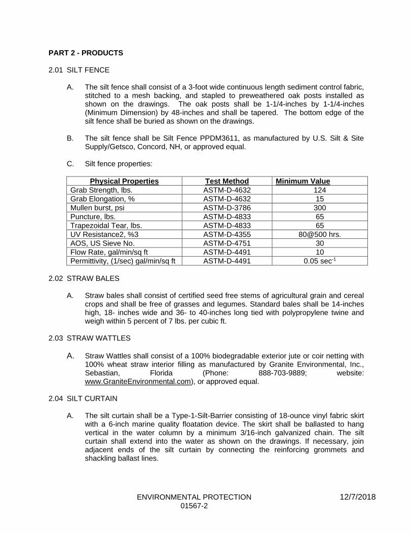
ENVIRONMENTAL PROTECTION 12/7/2018 01567-2
PART 2 - PRODUCTS 2.01 SILT FENCE
A. The silt fence shall consist of a 3-foot wide continuous length sediment control fabric, stitched to a mesh backing, and stapled to preweathered oak posts installed as shown on the drawings. The oak posts shall be 1-1/4-inches by 1-1/4-inches (Minimum Dimension) by 48-inches and shall be tapered. The bottom edge of the silt fence shall be buried as shown on the drawings.
B. The silt fence shall be Silt Fence PPDM3611, as manufactured by U.S. Silt & Site
Supply/Getsco, Concord, NH, or approved equal. C. Silt fence properties:
Physical Properties Test Method Minimum Value
Grab Strength, lbs. ASTM-D-4632 124
Grab Elongation, % ASTM-D-4632 15
Mullen burst, psi ASTM-D-3786 300
Puncture, lbs. ASTM-D-4833 65
Trapezoidal Tear, lbs. ASTM-D-4833 65
UV Resistance2, %3 ASTM-D-4355 80@500 hrs.
AOS, US Sieve No. ASTM-D-4751 30
Flow Rate, gal/min/sq ft ASTM-D-4491 10
Permittivity, (1/sec) gal/min/sq ft ASTM-D-4491 0.05 sec-1
2.02 STRAW BALES
A. Straw bales shall consist of certified seed free stems of agricultural grain and cereal
crops and shall be free of grasses and legumes. Standard bales shall be 14-inches high, 18- inches wide and 36- to 40-inches long tied with polypropylene twine and weigh within 5 percent of 7 lbs. per cubic ft.
2.03 STRAW WATTLES
A. Straw Wattles shall consist of a 100% biodegradable exterior jute or coir netting with 100% wheat straw interior filling as manufactured by Granite Environmental, Inc., Sebastian, Florida (Phone: 888-703-9889; website: www.GraniteEnvironmental.com), or approved equal.
2.04 SILT CURTAIN
A. The silt curtain shall be a Type-1-Silt-Barrier consisting of 18-ounce vinyl fabric skirt with a 6-inch marine quality floatation device. The skirt shall be ballasted to hang vertical in the water column by a minimum 3/16-inch galvanized chain. The silt curtain shall extend into the water as shown on the drawings. If necessary, join adjacent ends of the silt curtain by connecting the reinforcing grommets and shackling ballast lines.

ENVIRONMENTAL PROTECTION 12/7/2018 01567-3
PART 3- EXECUTION 3.01 NOTIFICATION AND STOPPAGE OF WORK
The Engineer will notify the Contractor in writing of any non-compliance with the requirements of the Inland Wetlands and Water Course Commission. The Contractor shall, after receipt of such notice, immediately take corrective action. Such notice, when delivered to the Contractor or his authorized representative at the site of the work, shall be deemed sufficient for the purpose. If the Contractor fails to act promptly, the Owner may order stoppage of all or part of the work through the Engineer until satisfactory corrective action has been taken. No claim for an extension of time or for excess costs or damage incurred by the Contractor as a result of time lost due to any stop work orders shall be made unless it was later determined that the Contractor was in compliance.
3.02 AREA OF CONSTRUCTION ACTIVITY
A. Insofar as possible, the Contractor shall confine his construction activities to those areas defined by the plans and specifications. All land resources within the project boundaries and outside the limits of permanent work performed under this contract shall be preserved in their present condition or be restored to a condition after completion of construction at least equal to that which existed prior to work under this contract.
3.03 PROTECTION OF WATER RESOURCES
A. The Contractor shall not pollute streams, lakes or reservoirs with fuels, oils, bitumens, calcium chloride, acids or other harmful materials. It is the Contractor's responsibility to comply with all applicable Federal, State, County and Municipal laws regarding pollution of rivers and streams.
B. Special measures should be taken to insure against spillage of any pollutants into
public waters. 3.04 CONSTRUCTION IN AREAS DESIGNATED AS WETLANDS ON THE DRAWINGS
A. Insofar as possible, the Contractor shall make every effort to minimize disturbance within areas designated as wetlands. Total easement widths shall be limited to the widths shown.
B. The Contractor shall perform his work in such a way that these areas are left in the
condition existing prior to construction. C. The elevations of areas designated as wetlands shall not be unduly disturbed by the
Contractor's operations outside of the trench limits. If such disturbance does occur, the Contractor shall take all measures necessary to return these areas to the elevations which existed prior to construction.
D. In areas designated as wetlands, the Contractor shall carefully remove and stockpile
the top 24 inches of soil. This topsoil material shall be used as backfill for the trench excavation top layer. The elevation of the trench shall be restored to the preconstruction elevations wherever disturbed by the Contractor's operation.
ENVIRONMENTAL PROTECTION 12/7/2018 01567-4
E. The Contractor shall use a trench box, sheeting or bracing to support the excavation in areas designated as wetlands.
F. Excavated materials shall not be permanently placed or temporarily stored in areas
designated as wetlands. Temporary storage areas for excavated material shall be as required by the Engineer.
G. The use of a temporary gravel roadway to construct the pipeline in the wetlands area
is not acceptable. The Contractor will be required to utilize timber or rubber matting to support his equipment in these areas. The timber or rubber matting shall be constructed in such a way that it is capable of supporting all equipment necessary to install the pipeline. The timber or rubber matting shall be constructed of materials and placed in such a way that when removed the material below the matting will not be unduly disturbed, mixed or compacted so as to adversely affect recovery of the existing plant life.
H. Bentonite dams shall be placed in wetlands to prevent drainage. Locations for dams
are as indicated on the drawings or as required by the Engineer. I. During construction, easements within wetlands shall be lined with a continuous
straw/hay bale/siltation fence barrier or line of straw wattles (aka compost filter tube, silt/filter sock).
3.05 PROTECTING AND MINIMIZING EXPOSED AREAS
A. The Contractor shall limit the area of land which is exposed and free from vegetation during construction. In areas where the period of exposure will be greater than two (2) months, temporary vegetation, mulching or other protective measures shall be provided as specified.
B. The Contractor shall take account of the conditions of the soil where temporary cover
crop will be used to insure that materials used for temporary vegetation are adaptive to the sediment control. Materials to be used for temporary vegetation shall be approved by the Engineer.
3.06 LOCATION OF STORAGE AREAS
A. The location of the Contractor's storage areas for equipment and/or materials shall be upon cleared portions of the job site or areas to be cleared as a part of this project, and shall require written approval of the Engineer. Plans showing storage facilities for equipment and materials shall be submitted for approval of the Engineer.
B. No excavated materials or materials used in backfill operations shall be deposited
within a minimum distance of one hundred (100) feet of any watercourse or any drainage facility. Adequate measures for erosion and sediment control such as the placement of baled hay or straw around the downstream perimeter of stockpiles shall be employed to protect any downstream areas from siltation.
C. There shall be no storage of equipment or materials in areas designated as
wetlands.
ENVIRONMENTAL PROTECTION 12/7/2018 01567-5
D. The Engineer may designate a particular area or areas where the Contractor may store materials used in his operations.
E. Storage areas in cross-country locations shall be restored to pre-construction
conditions with the planting of native species of trees and shrubs. 3.07 PROTECTION OF LANDSCAPE
A. The Contractor shall not deface, injure, or destroy trees or shrubs nor remove or cut them without written authority from the Owner. No ropes, cables, or guys shall be fastened to or attached to any existing nearby trees for anchorages unless specifically authorized by the Engineer. Excavating machinery and cranes shall be of suitable type and be operated with care to prevent injury to trees which are not to be removed, particularly overhanging branches and limbs. The Contractor shall, in any event, be responsible for any damage resulting from such use.
B. Branches, limbs, and roots shall not be cut except by permission of the Engineer. All
cutting shall be smoothly and neatly done without splitting or crushing. When there is unavoidable injury to branches, limbs and trunks of trees, the injured portions shall be neatly trimmed and covered with an application of grafting wax or tree healing paint as directed.
C. Where, in the opinion of the Engineer, trees may possibly be defaced, bruised,
injured, or otherwise damaged by the Contractor's equipment or by his blasting or other operations, the Engineer may require the Contractor to adequately protect such trees by placing boards, planks, poles or fencing around them. Any trees or landscape feature scarred or damaged by the Contractor's equipment or operations shall be restored as nearly as possible to its original condition at the expense of the Contractor. The Engineer will decide what method of restoration shall be used, and whether damaged trees shall be treated and healed or removed and disposed of under the provisions of Section 02222, EARTHWORK FOR WATER DISTRIBUTION SYSTEMS.
D. Cultivated hedges, shrubs, and plants which could be injured by the Contractor's
operations shall be protected by suitable means or shall be dug up, balled and temporarily replanted and maintained. After construction operations have been substantially completed, they shall be replanted in their original positions and cared for until growth is re-established. If cultivated hedges, shrubs, and plants are injured to such a degree as to affect their growth or diminish their beauty or usefulness, they shall be replaced by items of a kind and quality at least equal to that existing at the start of the work.
3.08 CLEARING AND GRUBBING
A. The Contractor shall clear and grub only on the Owner's land or the Owner's easements, and only the area required for construction operations, as approved by the Engineer. Removal of mature trees (4 inches or greater DBH) will not be allowed on temporary easements.
B. The Contractor shall not remove trees in the Owner's temporary easements without
permission of the Engineer.

ENVIRONMENTAL PROTECTION 12/7/2018 01567-6
3.09 DISCHARGE OF DEWATERING OPERATIONS
A. Any water that is pumped and discharged from the trench and/or excavation as part of the Contractor's water handling shall be filtered by an approved method prior to its discharge into a receiving water or drainage system.
B. Under no circumstances shall the Contractor discharge water to the areas
designated as wetlands. When constructing in a wetlands area, the Contractor shall discharge water from dewatering operations directly to the nearest drainage system, stream, or waterway after filtering by an approved method.
C. The pumped water shall be filtered through filter fabric and baled hay/ straw, a
vegetative filter strip or a vegetated channel to trap sediment occurring as a result of the construction operations. The vegetated channel shall be constructed such that the discharge flow rate shall not exceed a velocity of more than 1 foot per second. Accumulated sediment shall be cleared from the channel periodically.
3.10 DUST CONTROL
A. During the progress of work, the Contractor shall conduct his operations and maintain the area of his activities, including sweeping and sprinkling of water as necessary, so as to minimize the creation and dispersion of dust. 1. If the Owner decides that it is necessary to use calcium chloride for
more effective dust control, then the Contractor shall furnish and apply the material as directed.
2. Calcium chloride shall be commercial grade, furnished in 100-pound, 5-ply bags, stored under weatherproof cover and stacked alternately for ventilation.
3. Application for dust control shall be at the rate of about 1/2 pound per square yard per application.
4. Calcium chloride shall not be used for dust control within a drainage basin or in the vicinity of any source of potable water.
3.11 SEPARATION AND REPLACEMENT OF TOPSOIL
A. Topsoil shall be carefully removed from cross-country areas where excavations are to be made, and separately stored to be used again as directed. The topsoil shall be stored in an area acceptable to the Engineer and adequate measures shall be employed to prevent erosion of said material.

ENVIRONMENTAL PROTECTION 12/7/2018 01567-7
3.12 BALED HAY OR STRAW
A. To trap sediment and to prevent sediment from clogging drainage systems, baled hay or straw shall be used where shown on the drawings. Care shall be taken to keep the bales from breaking apart. The bales should be securely staked to prevent overturning, flotation, or displacement. All deposited sediment shall be removed periodically. Hay bales shall not be placed within a waterway during construction of the pipeline crossing.
3.13 ERECTION AND MAINTENANCE OF SILT FENCE
A. Where indicated on the drawings or where required by the Engineer, the Contractor shall erect and maintain a temporary silt fence. In areas designated as wetlands, the Contractor shall line the limits of the construction easement with a silt fence. The silt fence shall be used specifically to contain sediment from runoff water and to minimize environmental damage caused by construction.
3.14 SURFACE RESTORATION OF CROSS COUNTRY AREAS
A. Plantings detailed on the drawings or as otherwise specified shall be installed when construction of the pipeline has been completed within the areas designated. A one-year guarantee of maintenance will be required on these plantings to ensure that they establish in the area.
3.15 CATCH BASIN PROTECTION (SILT SACKS)
A. Siltsacks shall be securely installed under the catch basin grate. All deposited sediment shall be removed periodically and at times prior to predicted precipitation to allow free drainage flow. Siltsacks shall be placed in all drainage system catch basins indicated on the drawings or within the work area as follows:
1. Remove Catch Basin Grate and place sack in opening leaving approximately six inches of the sack outside the frame. Replace the grate to hold the sack in place.
2. Siltsack is to be inspected every 2-3 weeks and after every major storm event.
3. When the yellow restraint cord is no longer visible, Siltsack is full and should be emptied.
4. To remove or empty Siltsack: a. Place a piece of 1-Inch diameter rebar through each of the lifting
loops on each side of the sack. b. Use heavy equipment to lift and carry Siltsack to an approved
area for dumping. c. Place Siltsack on the ground within dumping area. d. With heavy equipment, lift Siltsack by emptying straps. e. This will turn the Siltsack inside out emptying the bag. f. The bag can be disposed of or reused.
ENVIRONMENTAL PROTECTION 12/7/2018 01567-8
B. Prior to working in areas where catch basins are to be protected, each catch basin sump shall be cleaned of all debris and protected. The contractor shall properly dispose of all debris at no additional cost to the Owner.
3.16 STRAW WATTLES
A. The wattles will be placed in a shallow trench (2-3 inches deep) and staked in the ground using wooden stakes driven at 4-foot intervals. The wooden stakes will be placed at a minimum depth of 24-inches into the ground.
END OF SECTION

TRAFFIC REGULATION 3/17/2017 01570-1
SECTION 01570
TRAFFIC REGULATION
PART 1 GENERAL
1.01 DESCRIPTION
A. The work under this Section shall consist of maintaining and protecting traffic in
the project area as shown on drawings, included in Contract Documents or as otherwise required to the satisfaction of the applicable Local Regulatory Agencies, and the Owner. 1. Unless otherwise specified within the Contract Documents, the Contractor
must maintain pedestrian and vehicular traffic and permit access to businesses, factories, residences, and intersecting streets.
PART 2 PRODUCTS 2.01 TRAFFIC SIGNS
A. The Contractor shall furnish light(s) and maintain traffic signs as may be directed,
or may be necessary for the safe regulation, or convenience of traffic. 1. Said signs shall be as shown or noted on the Contract Drawings or
elsewhere herein, or if not specified, they shall be adequate for the regulation, safety, and convenience of traffic and in conformance with the applicable requirements of the State/Federal Manual on Uniform Traffic Control Devices.
2.02 BARRICADES
A. Suitably lighted barriers or barricades shall be furnished by the Contractor and put
up and maintained at all times during the night or daytime, around all open ditches, trenches, excavation, or other work potentially dangerous to traffic. 1. Such barricades shall be as shown on the Contract Drawings, or if not
shown, shall be constructed of 2 inch by 8-inch rough lumber, securely supported, braced and at least 3 feet high above the ground.
2. Barricades shall be placed on all sides and throughout the entire length and breadth of all open ditches, trenches, excavations, or other work which must be barred to the general public.
3. Barricades shall be properly painted to the satisfaction of the Local Regulatory Agency in order to retain a high degree of visibility to vehicular and pedestrian traffic.
2.03 FLASHERS
A. The Contractor shall furnish and securely fasten flashing units to signs, barricades,
and other objects in such numbers and for such lengths of time as are required for the maintenance and protection of traffic. 1. The flashers shall be in operation during all hours between sunset and
sunrise, and during periods of low visibility.
TRAFFIC REGULATION 3/17/2017 01570-2
2. Suitably lighted barricades shall be defined as barricades lit by flashers in accordance with this Section or other lighting methods approved by the Local Regulatory Agency in lieu thereof.
3. Flashers shall be placed along the entire length of the barricades at an interval no greater than 8 feet, center to center. Flashers shall be power operated, lens directed, enclosed light units which shall provide intermittent light from 70 to 120 flashers per minute, with the period of light emittance occurring not less than 25 percent of each on-off cycle, regardless of temperature.
4. The emitted light shall be yellow in color and the area of light on at least one face of the unit shall be not less than 12 square inches. The discernible light shall be bright enough to be conspicuously visible during the hours of darkness at a minimum distance of 800 feet from the unit under normal atmospheric conditions.
5. For units which beam light in one or more directions, the foregoing specifications shall apply 10 degrees or more to the side and 5 degrees or more above and below the photometric axis.
2.04 TEMPORARY BRIDGING
A. The Contractor shall include in his bid, bridging for trenches at all street and
driveway crossings in such manner as the Local Regulatory Agency may direct for the accommodation and safety of the traveling public, to provide facilities for access to private driveways for vehicular use, and to prevent blocking of intersecting traffic. 1. He shall erect suitable barriers around the excavation to prevent
accidents to the public and shall place and maintain, during the night, sufficient lights on or near the work.
2. A space of 20 feet must be left so that free access may be had at all times to fire hydrants and proper precautions shall be taken so that the entrances to fire hydrants and fire stations shall not be blocked or obstructed.
2.05 DETOURS
A. Temporary detours shall be constructed on the site as proposed by the
Contractor and approved by the Applicable State and/or Local Authorities required by the Contract Drawings or specified elsewhere herein. 1. Detours shall not have grades in excess of 10% anywhere along their
lanes unless otherwise shown on the Contract Drawings. Detours shall be smooth riding.
2. Suitable barricades shall be installed continuously along both sides of a detour where: a. The adjacent side slope is steeper than 1 on 6 inches. b. The Contractor's operations or equipment may operate within
20 feet of the detour. c. Other unsafe conditions requiring them for the protection of
traffic along the line of detour.
TRAFFIC REGULATION 3/17/2017 01570-3
2.06 MISCELLANEOUS
A. The Contractor may be required to employ traffic persons and take other such
reasonable means or precautions as the Local Regulatory Agency may direct, or as may be needed to prevent damage or injury to persons, vehicles, or other property, and to minimize the inconveniences and danger to the public by his construction operations.
PART 3 EXECUTION
3.01 CONTROL OF TRAFFIC
A. It shall be the sole responsibility of the Contractor to keep the Local
Regulatory Agencies (including but not limited to the Police and Fire Departments) pre-warned at least 72 hours in advance of changes in traffic patterns due to reduction of pavement widths or closing of streets.
B. The Contractor shall supply, install, maintain, adjust, move, relocate, and
store all signs, suitably lighted barricades, traffic cones, and traffic delineators, as necessary to carry out the traffic routing plan and maintain vehicular and pedestrian traffic. 1. All of this work shall meet with the requirements of the Local
Regulatory Agencies. 2. The Contractor shall maintain, relocate and operate barricades and
flashers throughout the life of this Contract.
C. Should the Contractor or his employees neglect to set out and maintain
barricades or lights, as required in these Specifications, the Owner immediately, and without notice, may furnish, install and maintain barricades or lights. 1. The cost thereof shall be borne by the Contractor and may be
deducted from any amount due or to become due to the Contractor under this Contract.
3.02 ACCESS TO PROPERTY AND UTILITIES
A. The Contractor shall arrange his operations to provide access to properties
along the street including temporary bridges to driveways, and provide access to fire hydrants, manholes, gate boxes, or other utilities. 1. Whenever any trench obstructs traffic in or to any public street, private
driveway, or property entrance, the Contractor shall take such steps as required to maintain necessary traffic and access including temporary bridging if required.
2. The Contractor shall confine his occupancy of public or traveled ways to the smallest space compatible with the efficient and safe performance of the work contemplated by the Contract.
TRAFFIC REGULATION 3/17/2017 01570-4
3. If the Contractor's operations or occupancy of any public street or highway, or the uneven surfaces over any trenches being maintained by the Contractor, interfere with the removal or sanding of snow or ice by the public authorities or adjoining land owners, in an ordinary manner with regular highway equipment, the Contractor shall be required to perform such services for the public authorities or adjoining owners without charge.
4. If the Contractor fails to do so, he shall reimburse the said authorities or adjoining owners or the Owner for any additional cost to them for doing such work occasioned by conditions arising from the Contractor's operations, occupancy, or trench surfaces, together with any damage to the equipment of said parties by those conditions or claims of any parties for damage or injury or less by reason of failure to remove snow or ice or to sand icy spots under these conditions.
5. The Contractor shall observe and obey all local and state laws, ordinances, regulations and permits in relation to the obstruction of streets and highways, keeping passageways open and protecting traffic where there may be danger from blasting or other construction activities.
B. The Contractor shall be held responsible for any damages that the Engineer,
Owner, Governmental units, or their heirs or assigns may have to pay as a consequence of the Contractor's failure to protect the public from injury, and the same may be deducted from any payments that are due or may become due to the Contractor under this Contract.
END OF SECTION
TRAFFICMEN 12/7/2018 01572-1
SECTION 01572
TRAFFICMEN PART 1 - GENERAL
1.01 WORK INCLUDED
A. This Section covers the provisions for furnishing trafficmen for traffic control and maintenance of traffic as described in Section 01570 TRAFFIC REGULATION.
B. Trafficmen will either by Uniformed Police Officers or Certified Flaggers as specified by the Owner or required by the Town or State.
1.02 DESCRIPTION
A. The Contractor shall coordinate with the local jurisdiction’s Traffic Control Officer and /
or Police Chief to determine the number of trafficmen deemed necessary to provide for public safety and to maintain a smooth flow of traffic through the construction area(s) affected.
1.03 RELATED WORK
A. Documents affecting the work of this Section include, but are not necessarily limited
to, General Conditions, Supplementary Conditions and Sections in this Division of
these Specifications. 1. Section 01545, Protection of Property 2. Section 01570, Traffic Regulation
PART 2 - PRODUCTS
2.01 CERTIFIED FLAGGERS A. Any flagger determined by the Engineer to be ineffective in controlling traffic may be
removed at the discretion of the Engineer. If a flagger is directed to be removed, the Contractor shall immediately comply with the directive from the Engineer and shall suspend operations as necessary until a qualified replacement can be provided. Such a suspension of operations shall not be considered as a basis for a claim or an extension of time.
B. Flaggers used during the performance of the Work shall possess a current certificate of satisfactory completion from a Department-approved flagger training program within the previous two years. All flaggers shall carry their approved flagging training program certification card with them while performing flagging duties. Flagger certifications shall remain valid for the duration of the project or the flagger shall be removed from the project.

TRAFFICMEN 12/5/2017
01572-2
C. Each flagger shall be equipped with the following: high visibility clothing, signaling, and safety devices as required by the Department of Transportation of the state where work is being performed.
D. Compensation for flaggers will be paid on an hourly basis for only the actual time spent flagging and payment will be made under Item 53, Traffic Control (Certified Flagger). No allowance or additional payment will be made for required training, equipment, travel time, transportation, or any administrative charges associated with the costs of flaggers.
E. If the Contractor elects to employ his own Certified Flaggers, the Contractor shall
provide proof of current certification and the reimbursement shall be at the prevailing wage rate with no markup.
F. Flagger rates shall be established and provided to the Owner at the start of the project.
2.02 UNIFORMED OFFICERS
A. Contractor shall provide the Traffic Control Officer with a minimum of 24 hours notice
indicating the time of day, street location and confirm number of officers required for traffic control.
B. Contractor shall give the Traffic Control Officer a minimum of 2 hours prior cancellation
notice should Contractor determine that due to weather or conditions beyond his control he would not need the scheduled officers.
C. Contractor shall pay for officer(s) at the prevailing rate established by the local police
department should officers not be needed and the Contractor fails to cancel the officers as noted in 2.01.B above.
D. Where the Owner is paying directly for Traffic Officers and the Contractor cancels
scheduled officers, the Contractor shall be responsible for payment of the wages for cancellations if not cancelled in accordance with 2.02.B and 2.02.C above.
PART 3 - EXECUTION
3.01 OPERATION
A. Contractor shall provide barricades, barrier fences, traffic signs, and other traffic control devices as required by the Owner’s trafficmen, or as required by the Engineer, to protect the work area from traffic, pedestrians, and animals.
B. Contractor shall relocate barricades, signs and other devices as necessary as the work
progresses as required by the trafficmen or the Engineer.
END OF SECTION
PRODUCT HANDLING 3/17/2017 01610-1
SECTION 01610
PRODUCT HANDLING
PART 1 GENERAL
1.01 DESCRIPTION
A. Work included: Protect products scheduled for use in the Work by means including, but not necessarily limited to, those described in this Section.
1.02 QUALITY ASSURANCE
A. Include within the Contractor's quality assurance program such procedures as are required to assure full protection of work and materials.
1.03 MANUFACTURER'S RECOMMENDATIONS
A. Comply with manufacturers' recommendations on product handling, storage and protection.
1.04 PACKAGING
A. Deliver products to the job site in their manufacturer's original container, with labels intact and legible. 1. Maintain packaged materials with seals unbroken and labels intact until
time of use. 2. Promptly remove damaged material and unsuitable items from the job site,
and promptly replace with material meeting the specified requirements, at no additional cost to the Owner.
B. The Owner may reject as non-complying such material and products that do not
bear identification satisfactory to the Owner as to manufacturer, grade, quality and other pertinent information.
1.05 PROTECTION
A. Mechanical equipment subject to damage by the atmosphere if stored outdoors, shall be stored in a building with a controlled environment. The building may be a temporary structure on the site or a building off the site.
B. PVC and HDPE pipe shall be covered to protect it from UV degradation.
C. The Contractor shall be responsible for securing the staging and project area to prevent stored materials from being stolen or damaged. The use of fences, locking storage containers, trailers or other means shall be employed by the Contractor at no additional cost to the Owner.
1.06 REPAIRS AND REPLACEMENTS
A. In event of damage, promptly make replacements and repairs to the approval of the Owner at no additional cost to the Owner.
PRODUCT HANDLING 3/17/2017 01610-2
B. The Contractor shall promptly replace any materials that are stolen or lost at no additional cost to the Owner.
B. Additional time required to secure replacements and to make repairs will not be considered by the Owner to justify an extension in the Contract Time of Completion.
PART 2 PRODUCTS (Not Applicable)
PART 3 EXECUTION (Not Applicable)
END OF SECTION
OWNER FURNISHED MATERIALS 12/7/2018 01640-1
SECTION 01640
OWNER FURNISHED MATERIALS
PART 1 GENERAL
1.01 DESCRIPTION
A. Work included: The Owner will furnish and directly pay for all pipe, fittings, valves and accessories, required for the replacement of the water mains as shown on the Contract Drawings. A list of owner furnished materials is included in Appendix F of these Contract Documents. It shall be the responsibility of the Contractor to coordinate delivery of the materials with the Owner and the Owner’s supplier and take special care to protect and not damage materials furnished by the Owner for use in the work by means including, but not necessarily limited to, those described in this Section.
1.02 RELATED WORK
A. Documents affecting the work of this Section include, but are not necessarily limited to, General Conditions, Supplementary Conditions and Sections in Division 1 of these Specifications
1. Section 01310 Construction Schedules
2. Section 01610 Product Handling
1.03 COORDINATION
A. The Contractor shall be responsible for coordinating delivery of and accepting delivery of materials with the Owner and Owner’s suppliers for all material deliveries.
B. The Contractor shall be aware that delivery and pickup schedules may change. The Contractor shall be prepared to make trips to the Owner’s suppliers to obtain or return materials and to the site for delivery and pickup of materials as required at no additional cost to the Owner.
C. For delivery and pickup of materials, the Contractor shall supply all equipment
required to unload and load the material suppliers’ trucks at no additional cost to Owner.
D. It shall be the Contractor’s sole responsibility to, on a daily basis, inventory materials required for their planned work and notify the onsite representative and Owner if the materials required are not onsite. Claims for downtime due to materials not being onsite will not be considered.
OWNER FURNISHED MATERIALS 12/7/2018 01640-2
1.04 STORAGE AND PROTECTION OF MATERIALS
A. Upon delivery of the materials to the jobsite, materials shall be jointly inspected by the Contractor and the Owner’s representative, and upon acceptance by the Contractor it shall become his responsibility to unload, store, and protect Owner furnished materials, and to make good any damage to or loss of materials until the materials are incorporated and accepted in the work. Materials not used at the end of the job shall be stored at a designated storage area. The Contractor shall assist in loading any unused materials to the material suppliers’ trucks or deliver unused parts to the Owner’s yard if requested at no additional cost to the Aquarion Water Company.
PART 2 PRODUCTS (Not Applicable)
PART 3 EXECUTION (Not Applicable)
END OF SECTION

CONTRACT CLOSEOUT 3/17/2017 01700-1
SECTION 01700
CONTRACT CLOSEOUT
PART 1 GENERAL
1.01 DESCRIPTION
A. The work of this Section consists of procedures and requirements for contract
closeout, such as cleaning, restoration of project site to original condition,
inspections and guarantees.
PART 2 PRODUCTS (Not Applicable)
PART 3 EXECUTION
3.01 CLEANING UP
A. During its progress, the work and the adjacent areas affected thereby shall
be kept cleaned up and all rubbish, surplus materials, and unneeded
construction equipment shall be removed and all damage repaired so that the
public and property owners will be inconvenienced as little as possible.
B. Where material or debris has washed or flowed into or been placed in water-
courses, ditches, gutters, drains, catch basins, or elsewhere as a result of the
Contractor's operations, such material or debris shall be entirely removed and
legally disposed of during progress of the work, and the ditches, channels,
drains, etc., kept in a neat, clean and functioning condition.
C. On or before the completion of the work, the Contractor shall, unless
otherwise especially directed or permitted in writing, remove all rubbish from
any grounds which he has occupied; and shall leave the roads and all parts
of the premises and adjacent property affected by his operation in a neat and
satisfactory condition.
D. Unless otherwise specifically directed or permitted in writing, the Contractor
shall perform the following tasks:
1. Tear down and remove all temporary water mains, services, buildings and structures built by him.
2. Remove all temporary works, tools, and machinery or other
construction equipment furnished by him.
3. Remove, acceptably disinfect, and cover all organic matter and
material containing organic matter in, under, and around privies,
houses, and other buildings used by him.
a. Subsequent to disinfection, remove or suitably neutralize
disinfectant residuals from treated area(s).
4. Remove all rubbish from any grounds which he has occupied.
CONTRACT CLOSEOUT 3/17/2017 01700-2
5. Leave roads and all parts of premises and adjacent property affected by his operations in a neat and satisfactory condition.
3.02 RESTORATION
A. The Contractor shall restore or replace, when and as directed by the
Engineer, any public or private property damaged by his work, equipment, or employees, to a condition at least equal to that existing immediately prior to
the beginning of operations.
1. To this end, the Contractor shall do as required all necessary highway or driveway, walk, and landscaping work.
2. Suitable materials, equipment and methods shall be used for such restoration, or as required in other divisions of this Specification.
B. In restoring the disturbed areas the Contractor shall:
1. Replace any loam that has been removed during the excavation to a depth of 2 inches or to match existing; whichever is greater.
2. Remove from the property and legally dispose of in an approved
fashion all trees, brush and other items that the Contractor has cut in order to prosecute his work.
3. Remove from the property upon completion of the work thereon, all
excess materials of construction such as stone, pipe, concrete block, gravel, etc., that the Contractor may have stockpiled for use during
the course of the work. 4. Leave the land in a smooth, even condition. All ruts, holes or other
undesirable grading conditions which resulted from work under this
Contract shall be filled and the area so graded to eliminate ponding.
5. All drainage course(s) shall be restored to their pre-existing condition or better.
6. Reset all public or private monuments, iron pipes or other types of
property line and geodetic markers damaged or disturbed by
operations under this Contract. This work shall be done by a licensed land surveyor at no additional cost.
7. Repair, reset or replace as directed all pipes, walls, utilities, fences, railings, stone walls, etc., and ornamental or utilitarian domestic accessories, such as, but not limited to, arbors, fireplaces, sheds and incinerators, or other surfaces, structures, or property which may have
been damaged, either directly or indirectly by his operations under this Contract.
8. Restore to a condition at least equal to that in which they were found
immediately prior to the beginning of construction all sidewalks,
gutters, driveways and curbs which have been damaged by the Contractor's operations.
3.03 FINAL INSPECTION
A. At completion of all work, the Owner and Engineer, along with the General
Contractor and each of the subcontractors shall conduct a final inspection jointly for "punch list" purposes and to determine the exact status of the
project before final acceptance.
CONTRACT CLOSEOUT 3/17/2017 01700-3
3.04 GUARANTEES
A. The Contractor shall take notice of special guarantees required in the
technical Sections of these Specifications.
1. If, in the opinion of the Owner, any item requires excessive maintenance
during guarantee periods, the item shall be considered defective and the
Contractor shall correct the defects.
2. All defects so corrected shall be at the expense of the Contractor.
END OF SECTION
SUPPORT OF EXCAVATION 4/19/2018 02160-1
SECTION 02160
SUPPORT OF EXCAVATION
PART 1 GENERAL
1.01 DESCRIPTION
A. Provide excavation support as required by the Contract Documents.
1. In general this work shall consist of furnishing and placing timber
and/or steel sheeting and shoring of the types and dimensions
required for proper excavation support.
1.02 DEFINITIONS
A. Shoring shall mean the use of a steel trench box, steel sheeting, or timber
sheeting braced as required.
B. Timber sheeting shall mean the use of tongue and groove wood sheeting or
steel soldier beams with wood lagging braced as required.
C. Steel sheeting shall mean the use of steel sheet pilings with interlocking
joints, braced by steel members as required.
1.03 RELATED WORK
A. Documents affecting the work of this Section include, but are not necessarily
limited to, General Conditions, Supplementary Conditions and Sections in
Division 1 of these Specifications.
1. Section 02222 Earthwork for Water Distribution Systems 2. Section 02240 Site Drainage and Dewatering
3. Section 02611 Ductile Iron Pipe and Fittings
4. Section 02612 HDPE Pipe and Fittings 5. Section 02645 Hydrants
6. Section 02660 Service Connections
B. As established in the General Conditions of the Contract, the Contractor is solely responsible for means and methods of construction and for the
sequence and procedures to be used.
1.04 QUALITY ASSURANCE
A. Use adequate numbers of skilled workmen who are thoroughly trained and
experienced in the necessary crafts and who are completely familiar with the specified requirements and the methods needed for proper performance of
the work of this Section.
1. The Contractor shall not perform excavations in unstable ground and shall employ a positive means of containing the unstable ground
behind shoring, before excavation may proceed.

SUPPORT OF EXCAVATION 4/19/2018 02160-2
B. Employ a qualified Engineer, properly permitted to provide such services at
the location of the work, to design the shoring system and to inspect and
report on the quality of its construction.
C. Comply with all pertinent requirements of governmental agencies having jurisdiction.
D. Comply with all of Aquarion Water Company’s safety standards and directives.
1.05 STANDARDS
A. The following Standards form a part of this Specification as referenced:
1. ASTM A328, Specification for Steel Sheet Piling
2. Code of Federal Regulations (CFR), 29 CFR Part 1926 Subpart P -
Excavations, OSHA Standards - Excavation.
1.06 SUBMITTALS
A. Submit shoring design to Engineer for record purposes only.
PART 2 PRODUCTS
2.01 DESIGN
A. Design a shoring system which will safely and adequately prevent collapse
of adjacent materials and which will permit construction of the Work to the
arrangement shown on the Drawings.
B. All shoring systems shall be designed so as to support all vertical and lateral
loads and other surcharge loads imposed on the system during construction, including earth pressures, utility loads and other surcharged loads in order to
provide safe and expeditious construction of the permanent structures and
prevent movement and/or damage to adjacent soil, buildings, structures and utilities.
C. Secure all needed approvals, including those of governmental agencies
having jurisdiction and of adjacent property owners if required, at no
additional cost to the Owner.
2.02 MATERIALS
A Material shall include, but not necessarily be limited to sheet piling, soldier
piles, lagging, bracing members such as wales, struts, shores and tieback
anchors.
B. Lumber for timber sheeting and shoring:
1. Shall be sound Spruce, Douglas Fir, white or yellow Lodgepole,
Ponderosa pine, or western hemlock plank, planed on one side and either tongue and grooved or splined.
SUPPORT OF EXCAVATION 4/19/2018 02160-3
C. Steel sheeting:
1. Shall be of approved section and quality, either new or secondhand,
conforming to the requirements of ASTM A328.
PART 3 EXECUTION
3.01 SURFACE CONDITIONS
A. Examine the areas and conditions under which the work of this Section will
be performed. Correct conditions detrimental to timely and proper completion of the work. Do not proceed until unsatisfactory conditions are corrected.
3.02 INSTALLATION
A. Construct and install the shoring system in strict accordance with the design
engineer's requirements.
1. When using soldier piles and lagging, where boulders or cobbles are
encountered, soldier piles shall be installed in pre-augered holes over
the full depth as required to prevent misalignment and damage. 2. Vibration monitoring during installation and extraction of braced
excavation shall be provided wherever the excavation is within 100
feet of existing structures.
3.03 SHEETING LEFT IN PLACE
A. Sheeting left in place, for the purpose of preventing injury to structures,
utilities or other property, shall be cut-off three (3) feet below finished grade. 1. The right of the Engineer to order sheeting left in place shall not be
construed as creating any obligation on his part to issue such orders.
His failure to exercise his right to do so shall not relieve the Contractor
from liability for damages to persons or property occurring from or
upon the work occasioned by negligence or otherwise growing out of
a failure, on the part of the Contractor, to leave in place sufficient
sheeting to prevent movement of the ground.
3.04 SHEETING REMOVED
A. All sheeting not left in place shall be carefully removed in such manner as to
not endanger the construction or other structures, utilities, or property.
1. All voids left or caused by withdrawal shall be immediately refilled with approved material, and compacted with tools especially adapted to
that purpose. 2. Vibratory extraction methods shall be used only when it can be
demonstrated that settling of pipe and structures will not occur. If such
settling occurs, it shall be corrected at the Contractor's expense.
SUPPORT OF EXCAVATION 4/19/2018 02160-4
3.05 TRENCH BOX OR SHIELD
A. Use of a trench box or shield shall not relieve the Contractor of any liability for
damages to persons or property growing out of a failure of the Contractor to
leave in place sufficient sheeting and bracing to prevent the caving or moving
of the ground or disturbance of the completed work.
1. Care shall be taken, when a trench box or shield is moved ahead, so as
not to pull apart the joints of pipe already placed or leave voids around the pipe wall. At no time shall the portable box or shield be allowed to be
positioned below the spring line of the pipe.
2. The width of the trench box or shield shall be such that a minimum 6-inch
horizontal clearance is maintained between the pipe and shield at all times 3. If the pipe has moved, it shall be reset to the proper line and grade.
4. Any voids between the trench box or shield and the undisturbed trench wall within the pipe zone (bottom of trench to top of cover material) shall be filled with crushed stone, bank run gravel, or approved material,
immediately after the box or shield is positioned.
END OF SECTION
EARTHWORK FOR WATER DISTRIBUTION SYSTEMS 10/1/2021 02222-1
SECTION 02222
EARTHWORK FOR WATER DISTRIBUTION SYSTEMS PART 1 GENERAL
1.01 DESCRIPTION
A. Work Included: Provide all earthwork as required by the Contract Documents.
B. In general, the work of this Section shall include but not necessarily be limited to,
excavation, trenching, filling, backfilling, compaction and grading for water distribution systems.
1.02 RELATED WORK
A. Documents affecting the work of this Section include, but are not necessarily
limited to, General Conditions, Supplementary Conditions, and Sections in Division 1 of these Specifications.
1. Section 02160 Support of Excavation
2. Section 02227 Rock Removal
3. Section 02240 Site Drainage and Dewatering
4. Section 02611 Ductile Iron Pipe and Fittings
5. Section 02640 Buried Valves and Appurtenances
6. Section 02930 Loam and Seed
1.03 SITE INVESTIGATION
A. The grades and other site information have been compiled by field surveys.
1. The Contractor acknowledges that he has satisfied himself as to the nature and location of the work.
2. Failure by the Contractor to acquaint himself with all available information concerning the site will not relieve him from the responsibility, for estimating properly, the difficulty or cost of successfully performing the work.
1.04 QUALITY ASSURANCE
A. Use adequate numbers of skilled workmen who are thoroughly trained and
experienced in the necessary crafts and who are completely familiar with the specified requirements and the methods needed for proper performance of the work of this Section. 1. Use equipment adequate in size, capacity, and numbers to accomplish
the work in a timely manner. 1.05 PROTECTION OF PROPERTY AND UTILITIES
A. Extreme care shall be exercised to prevent damage to existing trees, shrubs,
utilities, walls, sidewalks, fences and private property. 1. Any damage to these items as a result of work performed by the Contractor

EARTHWORK FOR WATER DISTRIBUTION SYSTEMS 10/1/2021 02222-2
shall be repaired by the Contractor at his own expense. 2. Existing property boundary markers, control points and datum elevation
markers or bench marks shall be preserved.
a. All such items which are displaced or destroyed by the Contractor shall be replaced by a registered Engineer or Land Surveyor, as required, with all expenses paid by the Contractor.
B. Utility agencies shall be contacted and advised of proposed work prior to the
start of work by the Contractor. 1. Notify Call Before You Dig / Dig Safe. 2. Obtain information from the proper sources and authorities concerning
locations of all utilities within the scope of this work. 3. If and when encountered, utilities shall be supported and protected, and
the Engineer shall be notified. a. Ample time shall be allowed for entrance and taking such
measures as may be required for the continuance of such services by the utility owner.
4. Rules and regulations governing the respective utilities shall be observed. The Contractor's responsibilities with respect to utility locations, protection, interferences and relocations shall be as further specified in Section 01013.
1.06 REFERENCE STANDARDS
A. The Contractor shall comply with the provisions of the following agencies as
they apply to this project. 1. Associated General Contractors of America, Inc. (AGCA) "Manual of
Accident Prevention in Construction." 2. Occupational Safety and Health Administration, United States
Department of Labor Requirements 3. ANSI "Safety Regulations for Construction and Demolition". 4. American Society for Testing & Materials (ASTM) 5. American Water Works Association Standards 6. State Highway Department Specifications
1.07 SUBMITTALS
A. Comply with pertinent provisions of Section 01300.
B. Testing and Samples:
1. Test reports on backfill materials, moisture density tests, in place density tests (ASTM D 1557 and D 1556).
2. Representative backfill and bedding samples and gradation tests (ASTM D 422).
3. Tests shall be in conformance with paragraph 3.16; compaction requirements and testing as specified herein.
1.08 TRAFFIC
A. While excavating and backfilling is in progress, traffic shall be maintained in a
manner as specified in Section 01570 Traffic Regulation.
EARTHWORK FOR WATER DISTRIBUTION SYSTEMS 10/1/2021 02222-3
PART 2 PRODUCTS
2.01 GENERAL
A. Except as specified for pipe bedding, pipe cover, roadway subbase, and refill for
rock and unsuitable materials, backfill materials may be as follows: 1. Suitable materials for trench backfill shall be the material excavated during
the course of construction, but excluding debris, pieces of pavement, frozen materials, organic matter, silt, top soil, ledge excavation and rocks over six inches in largest dimension.
2. Gradation of material shall be generally as specified for gravel borrow except that maximum size of stone shall be 6 inches.
3. The suitability of existing material for use as backfill will be determined by the Engineer.
4. All unsuitable materials shall be disposed of as per paragraph 3.15.
B. In addition to the requirements of CT DOT Form 818 or current CT DOT standard, the following conditions apply:
1. Reclaimed Material, including but not limited to, Reclaimed Concrete Aggregate, Reclaimed Miscellaneous Aggregate, and Reclaimed Waste is not approved for use on the Owner’s property or easements granted to the Owner.
2. Reclaimed / Recycled processed material may be used by the Contractor within the limits of paved roadways on Aquarion Pipeline projects provided the following requirements are met:
a. The reclaimed / recycled processed material meets the approval of the Town or State having jurisdiction over the roadway and approval is provided in writing by such agency to the Owner and Engineer.
b. Sieve analysis demonstrating that the material meets the requirements under CT DOT M.05.01 for processed aggregate base or the applicable gradations under CT DOT M.02 where specifically required by the Owner and agency having jurisdiction over the paved roadway.
c. Proctor test results with moisture-density curve.
d. Environmental test report documenting that the proposed processed material meets the minimum testing requirements of CT DOT Form 818 or current CT DOT Standard.
e. Any additional testing as required by the agency having jurisdiction over the paved roadway.
2.02 PIPE BEDDING AND COVER MATERIAL
A. Ductile Iron Pipe:
1. Bank Run Gravel shall be a granular material, well graded from fine to coarse, with gradation as specified in paragraph 2.04 of this specification section, obtained from approved natural deposits and unprocessed except for the removal of unacceptable material and stones larger than the maximum size permitted.
2. It shall not contain vegetation, masses of roots, or individual roots. 3. It shall be free from loam and other organic matter, clay, and other fine or
harmful substances.
EARTHWORK FOR WATER DISTRIBUTION SYSTEMS 10/1/2021 02222-4
4. Bank Run Gravel shall conform to requirements as specified in paragraph 2.04 herein.
B. HDPE Pipe
1. Shall consist of clean inert, hard, durable grains of quartz or other hard durable rock free from loam or clay, surface coatings and deleterious materials.
2. Shall meet the requirements as specified in paragraph 2.07 herein. 3. The maximum particle size shall be 3/4 inch.
C. Water Service Tubing (PE / HDPE and Copper): 1. Sand shall consist of clean inert, hard, durable grains of quartz or other
hard durable rock free from loam or clay, surface coatings and deleterious materials.
2. The allowable amount of material passing a No. 200 sieve as determined by AASHTO shall not exceed 10 percent by weight.
3. The maximum particle size shall be 3/8 inch. 2.03 CONCRETE SAND
A. Concrete sand shall meet ASTM C-33 for fine aggregate.
2.04 BANK RUN GRAVEL
A. Bank run gravel shall consist of sound, tough, durable particles of crushed or
uncrushed material free from soft, thin, elongated, laminated, friable, micaceous, or disintegrated pieces, mud, loam, organic matter, clay, or other deleterious material.
Sieve Size Percent Passing by Weight
2 inch 100 1-1/2 inch 90-100 1 inch 20-55 ¾ inch 0-15 3/8 inch 0-5
2.05 PROCESSED AGGREGATE BASE
A. Shall meet the requirements of the jurisdiction where the work under this Contract is being performed and shall be the product resulting from the deliberate mechanical crushing of rock and gravel. Processed aggregate shall not contain stones larger than 2-1/2 inches and shall meet the following gradation:
Sieve Size Percent Passing by Weight
2-1/2 inch 100 2 inch 95-100 3/4 inch 50-75 1/4 inch 25-45 No. 40 5-20 No. 100 2-12
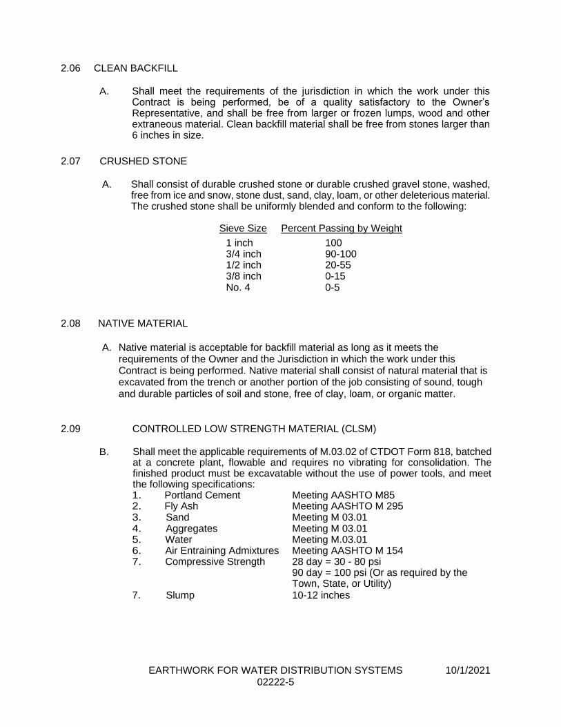
EARTHWORK FOR WATER DISTRIBUTION SYSTEMS 10/1/2021 02222-5
2.06 CLEAN BACKFILL
A. Shall meet the requirements of the jurisdiction in which the work under this
Contract is being performed, be of a quality satisfactory to the Owner’s Representative, and shall be free from larger or frozen lumps, wood and other extraneous material. Clean backfill material shall be free from stones larger than 6 inches in size.
2.07 CRUSHED STONE
A. Shall consist of durable crushed stone or durable crushed gravel stone, washed,
free from ice and snow, stone dust, sand, clay, loam, or other deleterious material. The crushed stone shall be uniformly blended and conform to the following:
Sieve Size Percent Passing by Weight
1 inch 100 3/4 inch 90-100 1/2 inch 20-55 3/8 inch 0-15 No. 4 0-5
2.08 NATIVE MATERIAL
A. Native material is acceptable for backfill material as long as it meets the requirements of the Owner and the Jurisdiction in which the work under this Contract is being performed. Native material shall consist of natural material that is excavated from the trench or another portion of the job consisting of sound, tough and durable particles of soil and stone, free of clay, loam, or organic matter.
2.09 CONTROLLED LOW STRENGTH MATERIAL (CLSM)
B. Shall meet the applicable requirements of M.03.02 of CTDOT Form 818, batched
at a concrete plant, flowable and requires no vibrating for consolidation. The finished product must be excavatable without the use of power tools, and meet the following specifications: 1. Portland Cement Meeting AASHTO M85 2. Fly Ash Meeting AASHTO M 295 3. Sand Meeting M 03.01 4. Aggregates Meeting M 03.01 5. Water Meeting M.03.01 6. Air Entraining Admixtures Meeting AASHTO M 154 7. Compressive Strength 28 day = 30 - 80 psi
90 day = 100 psi (Or as required by the Town, State, or Utility)
7. Slump 10-12 inches
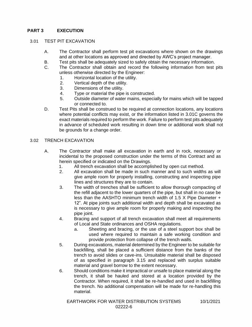
EARTHWORK FOR WATER DISTRIBUTION SYSTEMS 10/1/2021 02222-6
PART 3 EXECUTION
3.01 TEST PIT EXCAVATION
A. The Contractor shall perform test pit excavations where shown on the drawings
and at other locations as approved and directed by AWC’s project manager. B. Test pits shall be adequately sized to safely obtain the necessary information. C. The Contractor shall obtain and record the following information from test pits
unless otherwise directed by the Engineer: 1. Horizontal location of the utility. 2. Vertical depth of the utility. 3. Dimensions of the utility. 4. Type or material the pipe is constructed. 5. Outside diameter of water mains, especially for mains which will be tapped
or connected to. D. Test Pits shall be construed to be required at connection locations, any locations
where potential conflicts may exist, or the information listed in 3.01C governs the exact materials required to perform the work. Failure to perform test pits adequately in advance of scheduled work resulting in down time or additional work shall not be grounds for a change order.
3.02 TRENCH EXCAVATION
A. The Contractor shall make all excavation in earth and in rock, necessary or
incidental to the proposed construction under the terms of this Contract and as herein specified or indicated on the Drawings. 1. All trench excavation shall be accomplished by open cut method. 2. All excavation shall be made in such manner and to such widths as will
give ample room for properly installing, constructing and inspecting pipe lines and structures they are to contain.
3. The width of trenches shall be sufficient to allow thorough compacting of the refill adjacent to the lower quarters of the pipe, but shall in no case be less than the AASHTO minimum trench width of 1.5 X Pipe Diameter + 12”. At pipe joints such additional width and depth shall be excavated as is necessary to give ample room for properly making and inspecting the pipe joint.
4. Bracing and support of all trench excavation shall meet all requirements of Local and State ordinances and OSHA regulations. a. Sheeting and bracing, or the use of a steel support box shall be
used where required to maintain a safe working condition and provide protection from collapse of the trench walls.
5. During excavations, material determined by the Engineer to be suitable for backfilling, shall be placed a sufficient distance from the banks of the trench to avoid slides or cave-ins. Unsuitable material shall be disposed of as specified in paragraph 3.15 and replaced with surplus suitable material and gravel borrow to the extent necessary.
6. Should conditions make it impractical or unsafe to place material along the trench, it shall be hauled and stored at a location provided by the Contractor. When required, it shall be re-handled and used in backfilling the trench. No additional compensation will be made for re-handling this material.
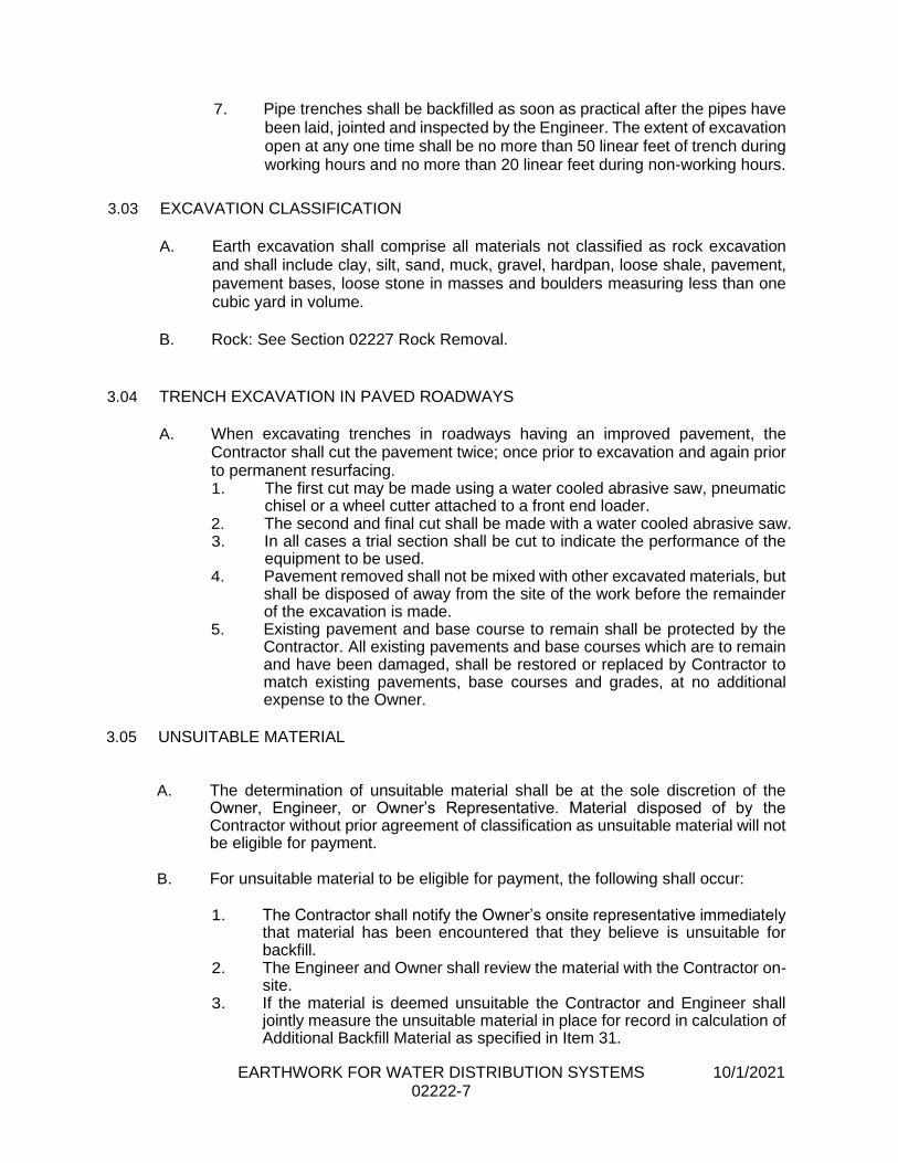
EARTHWORK FOR WATER DISTRIBUTION SYSTEMS 10/1/2021 02222-7
7. Pipe trenches shall be backfilled as soon as practical after the pipes have been laid, jointed and inspected by the Engineer. The extent of excavation open at any one time shall be no more than 50 linear feet of trench during working hours and no more than 20 linear feet during non-working hours.
3.03 EXCAVATION CLASSIFICATION
A. Earth excavation shall comprise all materials not classified as rock excavation
and shall include clay, silt, sand, muck, gravel, hardpan, loose shale, pavement, pavement bases, loose stone in masses and boulders measuring less than one cubic yard in volume.
B. Rock: See Section 02227 Rock Removal.
3.04 TRENCH EXCAVATION IN PAVED ROADWAYS
A. When excavating trenches in roadways having an improved pavement, the
Contractor shall cut the pavement twice; once prior to excavation and again prior to permanent resurfacing. 1. The first cut may be made using a water cooled abrasive saw, pneumatic
chisel or a wheel cutter attached to a front end loader. 2. The second and final cut shall be made with a water cooled abrasive saw. 3. In all cases a trial section shall be cut to indicate the performance of the
equipment to be used. 4. Pavement removed shall not be mixed with other excavated materials, but
shall be disposed of away from the site of the work before the remainder of the excavation is made.
5. Existing pavement and base course to remain shall be protected by the Contractor. All existing pavements and base courses which are to remain and have been damaged, shall be restored or replaced by Contractor to match existing pavements, base courses and grades, at no additional expense to the Owner.
3.05 UNSUITABLE MATERIAL
A. The determination of unsuitable material shall be at the sole discretion of the Owner, Engineer, or Owner’s Representative. Material disposed of by the Contractor without prior agreement of classification as unsuitable material will not be eligible for payment.
B. For unsuitable material to be eligible for payment, the following shall occur:
1. The Contractor shall notify the Owner’s onsite representative immediately that material has been encountered that they believe is unsuitable for backfill.
2. The Engineer and Owner shall review the material with the Contractor on-site.
3. If the material is deemed unsuitable the Contractor and Engineer shall jointly measure the unsuitable material in place for record in calculation of Additional Backfill Material as specified in Item 31.

EARTHWORK FOR WATER DISTRIBUTION SYSTEMS 10/1/2021 02222-8
C. The definition of unsuitable backfill material, in addition to the requirements set
forth in Item 2.01 of this Section, shall generally be defined as earth material not suitable for compaction, regardless of the required lift thickness to achieve adequate compaction. The Engineer may request sieve analysis and proctor testing be performed on the material for further analysis. Replacement material furnished for the purpose of reducing the number of lifts required to achieve sufficient compaction or material made unsuitable by the Contractor’s operations such as working in inclement weather or failure to suitably dewater an excavation will not be measured for payment.
D. The quantity of Additional Backfill Material shall be calculated utilizing the formula and parameters provided in Item 31 of Section 01025.
E. Payment width limits shall be the same as specified for trench excavation, unless an additional width of trench is ordered by the Engineer.
F. Any excavation in excess of the amount ordered by the Engineer shall be backfilled and compacted with an approved granular material, at the Contractors expense.
3.06 ROCK REMOVAL
A. See Specification Section 02227.
3.07 DEWATERING
A. See Specification Section 02240.
3.08 BACKFILLING AND COMPACTING
A. Backfill shall be placed in uniform layers. Each layer shall be thoroughly
compacted by tamping or vibrating with mechanical compacting equipment. 1. Care shall be taken to compact the backfill materials throughout the full
width of the excavation and beneath all pipes and structures. 2. The backfilling of trenches shall proceed as soon as the laying of the pipe
(s) or installation of the structures will allow. 3. Pipe bedding shall be placed to the limits as indicated in the Aquarion
Water Company’s Standard Details included in Appendix A. 4. After a pipe has been placed and bedded, the trench shall be filled to the
centerline of the pipe with pipe bedding and compacted. a. Material under and around the pipe shall be carefully and
thoroughly compacted and tamped with approved compacting equipment.
5. From the centerline of the pipe to a point 12 inches above the top of the pipe, the fill shall be pipe bedding.
B. Placement of Backfill Above the Pipe Bedding
1. For the portion of the trench twelve (12) inches above the pipe, backfill shall be suitable material from the excavation or, if ordered by the Engineer, shall be bank run, processed gravel or crushed stone. a. This backfill shall be placed in layers twelve (12) inches deep in
loose measure, and each layer shall be thoroughly compacted.
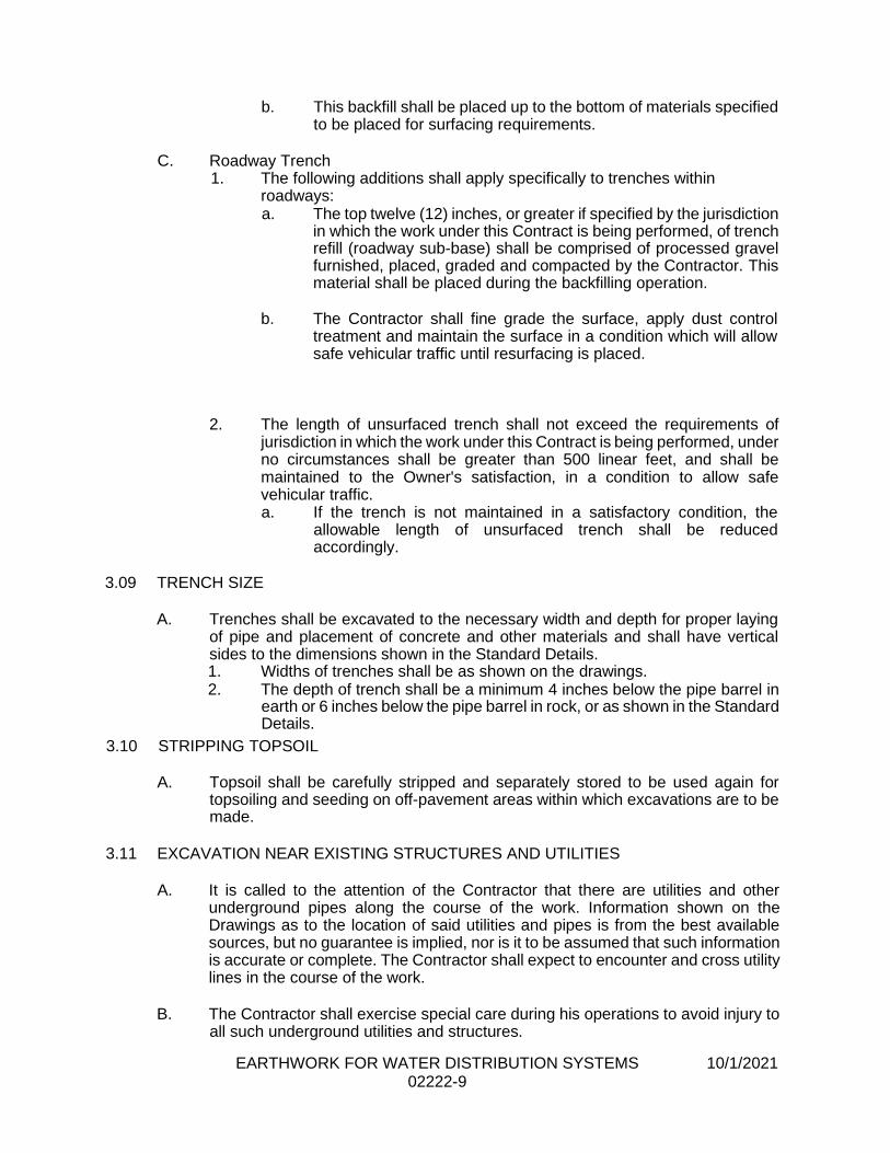
EARTHWORK FOR WATER DISTRIBUTION SYSTEMS 10/1/2021 02222-9
b. This backfill shall be placed up to the bottom of materials specified to be placed for surfacing requirements.
C. Roadway Trench
1. The following additions shall apply specifically to trenches within roadways: a. The top twelve (12) inches, or greater if specified by the jurisdiction
in which the work under this Contract is being performed, of trench refill (roadway sub-base) shall be comprised of processed gravel furnished, placed, graded and compacted by the Contractor. This material shall be placed during the backfilling operation.
b. The Contractor shall fine grade the surface, apply dust control
treatment and maintain the surface in a condition which will allow safe vehicular traffic until resurfacing is placed.
2. The length of unsurfaced trench shall not exceed the requirements of
jurisdiction in which the work under this Contract is being performed, under no circumstances shall be greater than 500 linear feet, and shall be maintained to the Owner's satisfaction, in a condition to allow safe vehicular traffic. a. If the trench is not maintained in a satisfactory condition, the
allowable length of unsurfaced trench shall be reduced accordingly.
3.09 TRENCH SIZE
A. Trenches shall be excavated to the necessary width and depth for proper laying
of pipe and placement of concrete and other materials and shall have vertical sides to the dimensions shown in the Standard Details. 1. Widths of trenches shall be as shown on the drawings. 2. The depth of trench shall be a minimum 4 inches below the pipe barrel in
earth or 6 inches below the pipe barrel in rock, or as shown in the Standard Details.
3.10 STRIPPING TOPSOIL
A. Topsoil shall be carefully stripped and separately stored to be used again for
topsoiling and seeding on off-pavement areas within which excavations are to be made.
3.11 EXCAVATION NEAR EXISTING STRUCTURES AND UTILITIES
A. It is called to the attention of the Contractor that there are utilities and other
underground pipes along the course of the work. Information shown on the Drawings as to the location of said utilities and pipes is from the best available sources, but no guarantee is implied, nor is it to be assumed that such information is accurate or complete. The Contractor shall expect to encounter and cross utility lines in the course of the work.
B. The Contractor shall exercise special care during his operations to avoid injury to
all such underground utilities and structures.

EARTHWORK FOR WATER DISTRIBUTION SYSTEMS 10/1/2021 02222-10
1. When necessary, the Contractor shall cooperate with, and consult with representatives of the Owner and the utility companies in order to avoid damage to the utilities.
2. The Contractor shall arrange for or furnish and erect suitable supports and shoring or other means of protection where required to protect the utilities, all at no additional cost to the Owner.
3. Hand methods of excavating shall be used around buried utilities and is included in the work to be performed under this Contract, at no additional cost to the Owner.
4. Interference between the proposed work and existing utilities, relocation of existing utilities, repair or damage to existing utilities, and protection and support of existing utilities during construction of the proposed work shall be as specified in Section 01013.
3.12 PROTECTION OF PROPERTY
A. The Contractor shall, at his own expense, preserve and protect from injury all
property either public or private along and adjacent to the line of work, and be responsible for and repair any and all damage and injury thereto, arising out of or in consequence of any act or omission by the Contractor. 1. All existing pipes, culverts, poles, wires, fences, mailboxes, stone walls,
curbs, bounds, etc., shall be temporarily removed, supported in place or otherwise protected from injury, and shall be restored to at least as good condition as that in which they were found immediately prior to the start of work.
2. Lawns, shrubs, bushes, planting beds and decorative trees disturbed or damaged shall be restored to a condition equal to that found prior to the start of construction, either by temporary transplant or replacement in kind, except as otherwise indicated on the Drawings.
3.13 SAFETY AND ACCOMMODATION
A. The Contractor shall provide, at his own expense, suitable bridges over trenches
where required for the accommodation and safety of the traveling public, and provide facilities for access to private driveways for vehicular use. 1. He shall erect suitable barriers around the excavation to prevent accidents
to the public and shall place and maintain during the night, sufficient lights on or near the work.
2. A space of twenty (20) feet shall be left so that free access may be had at all times to fire hydrants and proper precautions shall be taken so that the entrances to fire hydrants and fire stations shall not be blocked or obstructed.
3.14 COMPACTION REQUIREMENTS AND TESTING
A. All backfill materials shall be thoroughly compacted by rolling, tamping or vibrating
with approved mechanical or pneumatic compacting equipment so that pipe, structures, paving and other construction will not settle at the time of construction or in the future. The responsibility for thorough compaction is that of the Contractor irrespective of methods of backfill and depth of backfill layers placed.
B. All percentages of compaction specified herein shall be of the maximum dry density at the optimum moisture content as established by Method D of AASHTO
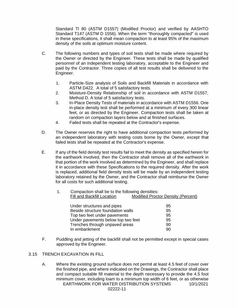
EARTHWORK FOR WATER DISTRIBUTION SYSTEMS 10/1/2021 02222-11
Standard Tl 80 (ASTM D1557) (Modified Proctor) and verified by AASHTO Standard T147 (ASTM D 1556). When the term "thoroughly compacted" is used in these specifications, it shall mean compaction to at least 95% of the maximum density of the soils at optimum moisture content.
C. The following numbers and types of soil tests shall be made where required by
the Owner or directed by the Engineer. These tests shall be made by qualified personnel of an independent testing laboratory, acceptable to the Engineer and paid by the Contractor. Three copies of all test results shall be delivered to the Engineer.
1. Particle-Size analysis of Soils and Backfill Materials in accordance with
ASTM D422. A total of 5 satisfactory tests. 2. Moisture-Density Relationship of soil in accordance with ASTM D1557,
Method D. A total of 5 satisfactory tests. 3. In-Place Density Tests of materials in accordance with ASTM D1556. One
inplace density test shall be performed at a minimum of every 300 linear feet, or as directed by the Engineer. Compaction tests shall be taken at random on compaction layers below and at finished surfaces.
4. Failed tests shall be repeated at the Contractor's expense.
D. The Owner reserves the right to have additional compaction tests performed by an independent laboratory with testing costs borne by the Owner, except that failed tests shall be repeated at the Contractor's expense.
E. If any of the field density test results fail to meet the density as specified herein for
the earthwork involved, then the Contractor shall remove all of the earthwork in that portion of the work involved as determined by the Engineer, and shall replace it in accordance with these Specifications to the required density. After the work is replaced, additional field density tests will be made by an independent testing laboratory retained by the Owner, and the Contractor shall reimburse the Owner for all costs for such additional testing.
1. Compaction shall be to the following densities:
Fill and Backfill Location Modified Proctor Density (Percent)
Under structures and pipes 95 Beside structure foundation walls 95 Top two feet under pavements 95 Under pavements below top two feet 95 Trenches through unpaved areas 90 In embankment 90
F. Puddling and jetting of the backfill shall not be permitted except in special cases
approved by the Engineer.
3.15 TRENCH EXCAVATION IN FILL
A. Where the existing ground surface does not permit at least 4.5 feet of cover over
the finished pipe, and where indicated on the Drawings, the Contractor shall place and compact suitable fill material to the depth necessary to provide the 4.5 foot minimum cover, including loam to a minimum top width of 6 feet, or as otherwise
EARTHWORK FOR WATER DISTRIBUTION SYSTEMS 10/1/2021 02222-12
shown on the Drawings. 1. Minimum side slopes shall be two horizontal to one vertical. 2. Fill material shall be from surplus suitable material or gravel borrow, and
be clean, dry, and capable of satisfactory compaction, all as approved by the Engineer, and shall be placed in layers not exceeding 12 inches thick and compacted.
3. The trench shall be excavated in the compacted fill and the remainder of the work shall be in accordance with other portions of these Specifications.
3.16 DISPOSAL OF SURPLUS AND UNSUITABLE EXCAVATED MATERIAL
A. All surplus excavated material and any material unsuitable for use shall be
disposed of in disposal areas provided by the Contractor. 1. It is the Contractor's responsibility to dispose of unsuitable excavated
material in an approved manner. 2. The Contractor shall not dispose of surplus materials on wetlands or other
areas prohibited by the Corps of Engineers or the State environmental governing body, or any other local authority having jurisdiction.
3.17 DUST CONTROL
A. The Contractor shall perform dust control operations as specified in Section
01567.
3.18 CLEAN-UP
A. Sweeping of debris related to water main installation shall take place on a daily
basis where directed by the Town, State, Owner, or Owner’s Representative.
B. All paved roadways affected by the construction shall have their full width swept clean (paved edge to paved edge) using methods which control the dust.
C. On a daily basis, where pavement sawcutting takes place, the roadway shall be
swept clean of all material expelled during the sawcutting process.
D. The Contractor shall remove all surplus materials (earth, pipe, fittings, storage and
office trailers, barricades, etc.), from the construction site.
E. Before the Contractor may proceed to another roadway, clean-up of the previous
roadway must be complete.
END OF SECTION
ROCK REMOVAL 12/7/2018 02227-1
SECTION 02227
ROCK REMOVAL
PART 1 GENERAL
1.01 DESCRIPTION
A. Work included: Remove all rock encountered while excavating for structures,
roadways, or utility trenches as required by the Contract Documents. Rock removal shall be accomplished by mechanical methods.
B. The use of explosives for removal of rock will not be permitted without written approval from the Owner and the State or Municipality in which the work under this Contract is being performed. When considering the use of explosives for rock removal, the Owner or Owner’s Representative shall require the Contractor to thoroughly demonstrate that all other means of rock removal have been exhausted. Any additional time or downtime required for the Owner’s or Owner’s Representative’s review of the Contractor’s blasting proposal shall be at no additional cost to the Owner.
1.02 RELATED WORK
A. Documents affecting the work of this Section include, but are not necessarily
limited to, General Conditions, Supplementary Conditions and Sections in Division 1 through Division 3 of these Specifications. 1. Section 02240 Site Drainage and Dewatering
2. Section 02222 Earthwork for Water Distribution Systems
1.03 DEFINITIONS
A. Rock shall be classified as sound bed rock or large boulders for which successful removal requires wedging, chipping or mechanical hammering for its removal.
Concrete shall be classified as rock.
B. The following types of material shall not be counted or permitted for payment as
rock excavation
1. Boulders less than one half (1/2) cubic yard which can be removed with
an excavator without mechanical hammering. 2. Loose, weathered, or deteriorated rock which can be removed with an
excavator without mechanical hammering. 3. Rock, stone masonry, concrete walls, or similar structures. 4. Previously blasted, fractured, or shot rock. 5. Concrete, asphalt, brick, or stone pavements, curbs, or walkways.
ROCK REMOVAL 12/7/2018 02227-2
1.04 STANDARDS A. All handling of explosives and blasting shall follow all applicable local, state, and
federal laws.
1.05 QUALITY ASSURANCE
A. Use adequate numbers of skilled workmen who are thoroughly trained and
experienced in the necessary crafts and who are completely familiar with the specified requirements and the methods needed for proper performance of the
work of this section.
B. Comply with all pertinent requirements of governmental agencies having
jurisdiction.
1.06 SUBMITTALS
A. Provide detailed submittals of the following:
1. Submit information detailing the proposed blasting company, proposed pre-blast and post-blast survey company, and the proposed seismic monitoring company.
2. Submit plans for proposed pre-blast survey (Record purposes only). 3. Provide detailed submittals on all chemicals to be used in the blasting and
included all Materials Safety Data Sheets (MSDS).
PART 2 PRODUCTS 2.01 DETONATORS
A. Detonators and detonation cord shall be contaminant free.
PART 3 EXECUTION
3.01 NOTIFICATION
A. When rock is encountered, it shall be uncovered and the Engineer notified.
1. The Contractor shall provide the Engineer with cross sections of the rock surface or a profile of the rock where trenches are concerned.
2. The Engineer shall be present when the cross sections or profiles are taken.
3. The average end area method shall be used in computing the volumes wherever practicable.
3.02 LIMITS OF EXCAVATION IN ROCK
A. Excavation in rock shall be performed, so that no projection shall come within
vertical planes twelve (12) inches outside of the structure being built or twelve (12) inches below the bottom of the structure base slab and footings.
ROCK REMOVAL 12/7/2018 02227-3
B. In trenches, the rock shall be removed to the limits shown on the typical trench detail.
1. Where excavation is carried beyond the above determined limits, the additional space shall be refilled at the Contractor's expense with concrete or other specified materials.
3.03 ROCK REMOVAL BY MECHANICAL METHOD
A. Excavate and remove rock by mechanical method.
1. Use pneumatic or hydraulically powered jack-hammer or drill holes and use expansive tools, wedges, and mechanical disintegration compound to fracture rock.
B. Cut away rock at bottom of excavation to form level bearing. C. Excavate to 6 inches below invert elevation of pipe and to the limits shown on the
typical trench detail. D. Remove excavated materials from the site in accordance with paragraph 3.04. E. Replacement fill material and backfilling shall be as specified in Section 02222.
3.04 ROCK REMOVAL BY EXPLOSIVES METHOD
A. Pre-Blast and Post-Blast Surveys: Prior to any blasting and at the completion of
blasting operations, the Contractor shall submit pre-blast and post-blast surveys.
1. The survey shall satisfy the insurance requirements of the Contractor and
be acceptable to the Contractor's insurance carrier, as well as provide data
to assess damages to personal property and real estate due to blasting
operations. 2. The surveys shall be complete as warranted by the nature of the work. 3. Pre-Blast surveys shall be submitted to the Owner prior to scheduling any
blasting operations. 4. The Contractor shall be present during the Pre-Blast and Post-Blast
surveys. 5. The Pre-Blast and Post-Blast surveys shall be conducted at the
Contractor’s expense and at no additional cost to the Owner.
B. Take all precautions necessary to warn and/or protect any individuals exposed
to his operations. Such precautions shall include but not be restricted to the following:
1. Present written certificate of insurance showing evidence that his
insurance includes coverage for blasting operations, before doing any
blasting work.
2. Make necessary arrangements as may be required by the applicable Federal, State, County or Municipal codes, rules, regulations and laws, and shall be responsible for compliance.
3. Obtain a permit from the local authorities to perform blasting operations.
a. The Engineer shall be notified in writing that such permit has been obtained.
4. Schedules for blasting shall be thoroughly coordinated with the proper authorities Federal, State and Local.
a. No blasting shall be done unless the Contractor has notified all
concerned parties that he may blast.
ROCK REMOVAL 12/7/2018 02227-4
b. The Contractor shall also notify any commercial installation in the
immediate area whose operations or instrumentation may be affected by blasting, at least twenty-four (24) hours prior to blasting
operations. 5. Seismographic recordings shall be made of all blasting operations on the
project by a qualified testing agency hired and coordinated by the
Contractor. a. A copy of these recordings shall be delivered to the Engineer for
record purposes. b. Seismic monitoring shall be conducted at the Contractor’s expense
and at no additional cost to the Owner.
6. Blasting shall only be performed by persons who are licensed to use explosives.
7. The Contractor shall keep an accurate record of each blast and submit a copy to the Engineer. The record shall show the date, time, exact stationing
of the blast, the depth and number of drill holes, and kind and quantity of explosive used, and any other data required for a complete record.
8. The Contractor shall be fully responsible for damages caused by his
blasting operations.
9. If rock below the limits of excavation is shattered by blasting, caused by
holes drilled to deep, too heavy a charge of explosives or any other circumstance due to blasting, the shattered rock shall be removed, and the
void refilled with gravel borrow at the expense of the Contractor. a. Gravel borrow shall be as specified in Section 02222 Earthwork for
Water Distribution Systems.
3.05 DISPOSAL AND REPLACING OF ROCK
A. Remove and dispose of all pieces of rock which are not suitable for use in other
parts of the Work.
1. Rock disposed of by hauling away to spoil areas shall be replaced by
surplus excavation obtained elsewhere on the site, insofar as it is available.
B. No fragments of rock larger than twelve (12) inches shall be used in backfilling.
C. Be responsible for obtaining spoil locations and the removal of all excess rock
from the site.
END OF SECTION

SITE DRAINAGE AND DEWATERING 9/10/2018
02240-1
SECTION 02240 SITE DRAINAGE AND DEWATERING PART 1 GENERAL 1.01 WORK INCLUDED
This section specifies designing, furnishing, installing, maintaining, operating and removing temporary dewatering systems as required to lower and control water levels and hydrostatic pressures during construction; disposing of pumped water; constructing, maintaining, observing and, except where indicated or required to remain in place, removing of equipment and instrumentation for control of the system.
1.02 RELATED WORK
A. Documents affecting the work of this Section include, but are not necessarily limited to, General Conditions, Supplementary Conditions and Sections in Division 1 through Division 3 of these Specifications. 1. Section 01567, ENVIRONMENTAL PROTECTION 2. Section 02160, SUPPORT OF EXCAVATION 3. Section 02222, EARTHWORK FOR WATER DISTRIBUTION SYSTEMS
1.03 SYSTEM DESCRIPTION
A. Dewatering includes lowering the water table and intercepting seepage which would otherwise emerge from the slopes or bottom of the excavation; increasing the stability of excavated slopes; preventing loss of material from beneath the slopes or bottom of the excavation; reducing lateral loads on sheeting and bracing; improving the excavation and hauling characteristics of sandy soil; preventing rupture or heaving of the bottom of any excavation; and disposing of pumped water. 1. Normal dewatering is defined as using conventional pumps installed in open
excavations, ditches, or sumps. 2. Special dewatering is defined as using single or two stage wellpoints, deep wells,
or eductor and ejector systems installed in drilled holes or jetted in place. 1.04 QUALITY ASSURANCE
A. The Contractor is responsible for the adequacy of the dewatering systems. He shall retain the services of a Professional Engineer registered in the state where the project is located, experienced in dewatering systems, to independently evaluate the boring logs and any other soils information available to determine those areas that will require special dewatering techniques and to design the required system. The Contractor's Professional Engineer shall provide sufficient on-site inspection and supervision to assure that the dewatering is carried out in accordance with his design.
SITE DRAINAGE AND DEWATERING 9/10/2018
02240-2
B. The dewatering systems shall be capable of effectively reducing the hydrostatic pressure and lowering the groundwater levels to a minimum of 2 feet below excavation bottom, unless otherwise required by the Engineer, so that all excavation bottoms are firm and dry.
C. The dewatering system shall be capable of maintaining a dry and stable subgrade until
the structures, pipes and appurtenances to be built therein have been completed to the extent that they will not be floated or otherwise damaged.
D. The dewatering system and excavation support (see Section 02160) shall be designed
so that lowering of the groundwater level within the work area does not adversely affect structures, utilities or wells outside of the work area.
E. Where special dewatering is used, the Contractor shall obtain at his expense the
services of a registered professional engineer to investigate, design and monitor the dewatering system. The Contractor shall also furnish materials and install at least two observation wells at each excavation area. The location of the wells shall be determined in the field by the Contractor’s engineer.
1.05 SUBMITTALS: IN ACCORDANCE WITH REQUIREMENTS OF GENERAL
SPECIFICATIONS, SUBMIT THE FOLLOWING
A. At least two weeks prior to installing his dewatering system, Contractor shall submit the attached Certificate of Design completed and signed by Contractor, identifying the engineer responsible for design of the dewatering system. He shall also submit a schedule showing the timing of installation and operation of the dewatering system.
B. The Contractor shall submit to the Engineer for record purposes only, the following
items bearing the Contractor's Engineer's stamp and signature, and identifying the codes and specifications followed in the design.
1. Plans and description of the dewatering system, including the number, location
and depth of wells, wellpoints or sumps; designs of filters to prevent pumping of fine soil; method and location for filtering and disposal of pumped water; and flow capacity of proposed system.
2. Locations of observation wells.
C. The Contractor shall submit records of pump operation and groundwater elevations as required by the Owner's Engineer.
PART 2 - PRODUCTS (NOT APPLICABLE)
SITE DRAINAGE AND DEWATERING 9/10/2018
02240-3
PART 3 - EXECUTION 3.01 DEWATERING OPERATIONS
A. All water pumped or drained from the work shall be disposed of in a manner which will not result in undue interference with other work or damage to adjacent properties, pavements and other surfaces, buildings, structures and utilities. Suitable temporary pipes, flumes or channels shall be provided for water that may flow along or across the site of the work. All disposal of pumped water shall conform to the provisions of Section 01567 ENVIRONMENTAL PROTECTION.
B. Dewatering facilities shall be located where they will not interfere with utilities and
construction work to be done by others.
C. Dewatering procedures to be used shall be as described below:
1. Crushed stone shall encapsulate the suction end of the pump to aid in minimizing the amount of silt discharged.
2. For dewatering operations with relatively minor flows, pump discharges shall be
directed into haybale sedimentation traps lined with filter fabric. Water is to be filtered through the haybales and filter fabric prior to being allowed to seep out into its natural water course.
3. For dewatering operations with larger flows, pump discharges shall be into a steel
dewatering basin. Steel baffle plates shall be used to slow water velocities to increase the contact time and allow adequate settlement of sediment prior to discharge into waterways.
4. Where indicated on the contract drawings or in conditions of excess silt suspended
in the discharge water, silt control bags are to be utilized in catchbasins. D. The Contractor shall be responsible for repair of any damage caused by his dewatering
operations, at no cost to the Owner. 3.02 SPECIAL DEWATERING
A. If conventional dewatering methods are inadequate to ensure dry and stable conditions for structural foundations, the Contractor shall be required to use special dewatering as necessary.
B. Special dewatering techniques may consist of one or two stage wellpoint systems,
deep wells, or eductor and ejector type systems. The Contractor shall utilize a system which provides proper construction conditions and prevents settlement at time of installation and upon backfilling.

SITE DRAINAGE AND DEWATERING 9/10/2018
02240-4
C. In areas requiring special dewatering, the Contractor shall lower the groundwater level to a minimum of 2 feet below the bottom of the final excavation grade prior to any installation and maintain that groundwater level until the excavation has been backfilled. The groundwater levels shall be monitored by the Contractor's engineer to ensure conformance with the requirements of these specifications. Construction will not be allowed until the Owner's Engineer is satisfied that the above provisions are met.
3.03 NOISE LEVEL REQUIREMENTS
A. All primary dewatering equipment shall be electrically operated and shall run on commercial power. Standby equipment shall be independent of commercial power and shall provide dewatering upon primary pump or power failure.
B. All equipment utilized by the Contractor shall conform to the regulations of the Federal,
State, and Local regulations. END OF SECTION

SITE DRAINAGE AND DEWATERING 9/10/2018
02240-5
CERTIFICATE OF DESIGN Re: Contract Between:
OWNER: (Name)
and CONTRACTOR:
(Name) on CONTRACT:
(Number) Date:
Title:
Contractor hereby certifies that :
(Engineer)
1. Is licensed or registered to perform professional engineering work in the state of ; (Location of Project)
2. Is qualified to design the
(Item) specified in Section of subject contract;
3. Has designed before; (Item)
4. Has prepared the design in full compliance with the applications and requirements of Section of subject contract including all applicable laws, regulations, rules, and codes; and
5. The work has been signed and sealed pursuant to applicable state law.
FOR: (Contractor)
BY: (Signature) (Name and Title)
Dated: Document5
TEMPORARY WATER SERVICE 12/7/2018 02511-1
SECTION 02511
TEMPORARY WATER SERVICE
PART 1 GENERAL
1.01 DESCRIPTION
A. The Contractor shall furnish, install, maintain, protect, make repairs if damaged
and remove temporary by-pass piping and temporary water services to all customers who will be out of service during the work of this Contract.
1.01 RELATED WORK
A. Documents affecting the work of this Section include, but are not necessarily
limited to, General Conditions, Supplementary Conditions and Sections in Division 1 through Division 3 of these Specifications.
1. Section 02222 Earthwork for Water Distribution System 2. Section 02675 Disinfection of Water Mains
1.02 QUALITY ASSURANCE
A. Use adequate numbers of skilled workmen who are thoroughly trained and
experienced in the necessary crafts and who are completely familiar with the specified requirements and the methods needed for proper performance of the
work of this Section.
B. Prior to commencing work, the Contractor shall submit for approval complete
details including type and proposed location of all by-pass piping, connections to existing mains and/or hydrants and temporary control valves with service connections along with a proposed schedule.
C. Coordinate the work of this Section with the work of other related Sections.
D. All pipe materials that come in contact with water shall be NSF approved for use
with potable water.
E. All work shall be scheduled to minimize water service interruption time.
F. The Contractor shall designate qualified personnel to be “on-call” 24 hours a day,
seven days per week, for making emergency repairs to the temporary by-pass system. An emergency phone number where “on call” personnel may be contacted
shall be provided to the Owner. Emergency repairs shall be performed at no additional cost to the Owner.
TEMPORARY WATER SERVICE 12/7/2018 02511-2
1.03 INSPECTION, TESTS AND ACCEPTANCE
A. All piping and materials shall be furnished by the Contractor for use as temporary service pipes and shall be clean, watertight and adequate to withstand existing system pressures and all other conditions of use and shall be approved by the Engineer. The Contractor shall submit a plan for the temporary by-pass system to the Engineer for approval showing the size and configuration of the piping, hydrants and appurtenances.
B. Prior to placing the temporary by-pass piping into service, the Contractor shall flush, chlorinate, and test piping in accordance with the requirements of AWWA C651, latest revision. Samples to confirm proper disinfection will be taken and tested by the Contractor. All tests shall be made in accordance with the methods prescribed by the above mentioned AWWA Standard, and the acceptance or rejection shall be based on the test results.
1.04 SUBMITTALS
A. Comply with pertinent provisions of Section 01300.
B. Product data: Within 30 calendar days after the Contractor has received the Owner's Notice to Proceed, submit:
1. Materials list of items proposed to be provided under this Section.
2. Manufacturer's specifications and other data needed to prove compliance
with the specified requirements.
PART 2 PRODUCTS
2.01 PIPE
A. The temporary service pipe, connections, and branches shall be of the highest
quality and shall be fully adequate to withstand the pressures and all conditions of use. The temporary service shall be made of fused-joint HDPE or PVC suitable for above-ground use. The installation shall be watertight.
PART 3 EXECUTION
3.01 SURFACE CONDITIONS
A. Examine the areas and conditions under which the work of this Section will be
performed. Correct conditions detrimental to timely and proper completion of the Work. Do not proceed until unsatisfactory conditions are corrected.
3.02 FIELD MEASUREMENTS
A. Make necessary measurements in the field to assure precise fit of the items.
TEMPORARY WATER SERVICE 12/7/2018 02511-3
3.03 PIPE HANDLING
A. Handling:
1. The Contractor shall take care not to damage pipe by impact, bending,
compression, or abrasion during handling, and installation. Joint ends of
pipe especially shall be kept clean.
2. Pipe shall be stored a minimum 4 inches above ground at a height no
greater than 5 feet, and with even support for the pipe barrel.
3. Only nylon-protected slings shall be used for handling the pipe. No hooks or bare cables shall be permitted.
4. Gaskets shall be shipped in cartons and stored in a clean area, away from
grease, oil, heat, direct sunlight and ozone producing electric motors. 3.04 INSTALLATION
A. Pipe:
1. Temporary by-pass piping shall be installed as shown on the Contract Drawings.
2. All temporary by-pass piping shall be installed within street lines and easements.
3. By-pass piping shall be installed as to not obstruct sidewalks, streets, or
driveways unless adequate precautions are taken to allow pedestrian and
vehicular traffic to safely and easily cross the piping at all times.
4. The by-pass piping may be temporarily buried or bridged underneath the
sidewalks, streets, or driveways.
5. Water for by-pass service shall be obtained from the existing water mains
and/or hydrants. A control valve shall be installed at each connection to the
existing main. Connection to fire hydrants shall be made in such a manner
that would permit use of the fire hydrant for firefighting purposes while the
temporary by-pass is operational.
6. When assembly of the bypass piping is not in progress, including lunch
time, the open ends of the pipe shall be closed by a watertight plug.
7. When cutting of pipe is required, the cutting shall be done by machine,
leaving a smooth cut at right angles to the axis of the pipe.
B. Service Connections:
1. The Contractor shall provide temporary pipe and fittings to connect the
existing water services for each customer as required to by-pass the pipe
being taken out of service.
2. If an interruption of water service is required, the Contractor shall provide
customers a minimum notice of 24 hours in advance of the interruption.
3. Each temporary service line shall include a flexible “whip” hose and a shut
off valve. All temporary piping shall meet the requirements of AWWA C602,
Section 4.6, latest revision.
4. In general, connections shall be made to exterior hose bibs; however, the
Contractor shall make provisions for alternate style connections as
needed.

TEMPORARY WATER SERVICE 12/7/2018 02511-4
C. Temporary Hydrant Connections: 1. A temporary hydrant shall be included in the bypass system for each hydrant
put out of service. The hydrant outlet thread pitch and size shall match that of the existing hydrants in the area. The temporary hydrant shall be in the close vicinity of the hydrant to be put out of service and shall be fed by a minimum of 4-inch diameter line. All temporary hydrants shall be suitably restrained and anchored to resist thrusts and forces encountered during the hydrant operation. Additionally, the local fire department shall be trained in the operation of the temporary hydrants.
D. Caps and Plugs:
1. Shall be provided with a threaded corporation or bleeder valve so that air
and water pressure can be relieved.
E. Thrust Blocking for Fittings:
1. As specified in Section 02650, Thrust Blocks and Joint Restraints.
F. Couplings:
1. Contractor shall provide all adapters and fittings such as transition
couplings, as determined in the field, necessary to complete all tie-ins,
whether or not specifically stated in the Specifications or on the Contract
Drawings.
3.05 DISINFECTING
A. Comply with the pertinent sections of Section 02675, Disinfection of Water
Mains.
END OF SECTION
BITUMINOUS CONCRETE PAVEMENT 12/7/2018 02513-1
SECTION 02513
BITUMINOUS CONCRETE PAVEMENT
PART 1 GENERAL
1.01 DESCRIPTION
A. Provide bituminous concrete pavement and appurtenant items as required
by the Contract Documents.
1. In general, the Contractor shall provide all labor, equipment, and
materials, and perform all operations in connection with the
installation of bituminous concrete pavement, curbs, pavement
markings, calcium chloride, final grade adjustments of valve boxes,
manhole and catch basin castings, and preparation of the trench.
1.02 RELATED WORK
A. Documents affecting the work of this Section include, but are not necessarily
limited to, General Conditions, Supplementary Conditions and Sections in
Division 1 of these Specifications. 1. Section 02222 Earthwork for Water Distribution Systems
1.03 STANDARDS
A. All paving shall comply with all applicable state highway standards,
hereinafter called Standard Specifications, as referenced.
1.04 SUBMITTALS
A. Comply with pertinent provisions of Section 01300.
B. Product data: Within 30 calendar days after the Contractor has received the Owner's Notice to Proceed, submit:
1. Materials list of items proposed to be provided under this Section.
2. Manufacturer's specifications and other data needed to prove
compliance with the specified requirements.
PART 2 PRODUCTS
2.01 GRAVEL SUBBASE
A. Shall be as specified in Section 02222, Earthwork for Water Distribution
Systems.
BITUMINOUS CONCRETE PAVEMENT 12/7/2018 02513-2
2.02 BITUMINOUS CONCRETE PAVEMENT
A. Courses:
1. Shall be of the types and minimum thicknesses shown on the
Contract Drawings. Thickness shall match the existing pavement
thickness where required by the Town or State.
2.03 ASPHALT TACK COAT
A. Shall consist of either emulsified asphalt, grade RS-1 conforming to the
requirements of the State/Town where work is being performed.
2.04 TRAFFIC LOOPS
A. All required materials including, but not limited to wire, tubing, and sealant
material shall meet the requirements of the Standard Specifications of the Town and or State having jurisdiction over the roadway.
2.05 PAVEMENT MARKING PAINT
A. Shall be High Heat Rapid Drying Traffic Marking Material conforming to the
requirements of the State/Town where work is being performed.
PART 3 EXECUTION
3.01 SURFACE CONDITIONS
A. Examine the areas and conditions under which work of this Section will be
performed. Correct conditions detrimental to timely and proper completion
of the Work. Do not proceed until unsatisfactory conditions are corrected.
3.02 FINAL PREPARATION OF SUBGRADES
A. Gravel Subbase:
1. Minimum compacted depth shall be shown on the Contract
Drawings.
2. Spread and compacted in layers not exceeding 6 inches in depth,
compacted measurement.
3. All layers shall be compacted to not less than 95 percent of the
maximum dry density of the material as determined by the standard
AASHTO Test Designation T99 Compaction Test Method C at
optimum moisture content.
3.03 GENERAL
A. All bituminous concrete pavement thickness referred to in this Section
shall be compacted thickness.
BITUMINOUS CONCRETE PAVEMENT 12/7/2018 02513-3
B. Trench Pavement shall be installed as shown on the Drawings or as required by municipality or state where work is performed.
C. The Contractor is responsible for the installation of temporary hot-mix trench pavement as soon as practicable, but not later than the last day of the work week. If required by the Town or State, temporary hot-mix trench pavement shall be placed on a daily basis. Temporary trench shall be as shown in the Trench Paving Details on the Contract Drawings. Top of temporary pavement shall be flush with existing pavement. The Contractor shall maintain all temporary trench pavements for the duration of the contract.
1. When trench settlement is deemed to be unacceptable. Any settled
areas shall be repaired to the requirements of the governing state or municipality at no additional cost to the Owner.
B. No bituminous concrete pavement shall be placed when the air temperature
is below forty (40) degrees Fahrenheit, or when the material on which the
mix is to be placed contains frost.
C. The finished bituminous concrete surface (temporary and permanent) shall
be level with the adjacent pavement and consistent with the slope of the
road.
D. Maintain bituminous concrete under this Contract during the guarantee
period of one (1) year for town roads and driveways and three (3) years for
state roads.
3.04 COLD MILLING OF PAVEMENT
A. After the temporary pavement has sufficient time to settle, after one winter season, or at the direction of the Town or State, the bituminous concrete pavement surface shall be removed by cold planning to the nominal depth and width shown on the Contract Drawings.
B. Any bituminous concrete that cannot be removed by cold planning equipment shall be removed by other approved means. Care shall be taken to avoid damaging existing structures such as catch basins, valve boxes, manholes, or other castings present within the roadway. Existing structures damaged by the Contractor during milling shall be repaired to the Utility Owner, Town, or State’s satisfaction at the Contractor’s expense.
C. The Contractor shall utilize a self-propelled milling machine with sufficient power, traction and stability to remove the specified depth of bituminous concrete surface, while automatically maintaining uniform profile, cross slope, and controlling grade elevation.
BITUMINOUS CONCRETE PAVEMENT 12/7/2018 02513-4
D. The milling machine shall use a ski or matching shoe to accurately control profile grades (within + 1/8-inch tolerance) along the edge of the machine in relation to the existing pavement or an independent grade line.
E. The machine shall be equipped with an integral loading system to immediately remove material being cut from the surface of the roadway and discharge cuttings into a truck, all in one operation. All milling machinery shall be equipped with dust-control devices to prevent any dust produced in the cutting operation from escaping into the air.
F. Final milled surface shall be thoroughly swept and be free of broken pavement, dust or gravel.
G. In the event the milled surface is opened to traffic, the Contractor shall provide temporary ramps at all structures, entrances, exits and transitions between milled and un-milled pavement as required by the Town or State at no additional cost to the Owner. Ramps shall be maintained by the Contractor until placement of final pavement. Immediately prior to placement of final pavement, temporary ramps shall be removed, and the area toughly swept clean.
3.05 PLACEMENT OF BITUMINOUS CONCRETE PAVEMENT
A. Temporary Pavement (All Roads): 1. Place after underground facilities have been installed. 2. Pavement shall be the type as specified in this Section except that
"cold-mix" will be acceptable, if approved by the Town or State having jurisdiction, for repairs during seasonal closure of the bituminous concrete supplier.
3. Compacted thickness shall be as shown in the Trench Paving Details on the Contract Drawings.
B. Permanent Pavement Town Roads and Driveways:
1. Base Course:
a. Pavement compacted thickness shall be as shown on the
Contract Drawings or required by the Town.
b. Placed with a self- propelled spreader.
c. Compaction shall be accomplished with a self-propelled
roller, with a weight of approximately 285 pounds per inch of
roller width.
d. Base course pavement shall be maintained by the Contractor
until permanent top course pavement is placed.
2. Top Course:
a. Base course pavement shall remain in place.
b. The base course shall be swept clean of all foreign matter
and loose material.
c. Depressions in the base course resurfacing shall have a
BITUMINOUS CONCRETE PAVEMENT 12/7/2018 02513-5
leveling course applied before the top course paving begins.
d. The surface receiving the top course shall be completely dry
prior to the application of the tack coat.
e. An approved tack coat shall be applied at the rate of 0.25
gallons per square yard. The contact surface of the curbing,
castings and other structures shall be painted with the tack
coat.
f. All castings (frames and covers, valve boxes), shall be raised
to finish grade before the top course is applied.
g. The equipment used for spreading and finishing shall be a
mechanical self-powered paver capable of spreading and
finishing the mixture true to line, grade, width and crown by
means of fully automated controls for both longitudinal and
transverse slope. h. Top course pavement compacted thickness shall be as shown
on the Contract Drawings or required by the Town.
l Compaction shall be accomplished with a self-propelled roller
with a weight of approximately 285 pounds per inch of roller
width.
B. PERMANENT PAVEMENT (STATE ROADS):
1. Base Courses:
a. The vertical faces of the adjoining existing pavement shall be
coated with rapid setting Type-I (RS-1) emulsion
b. Pavement compacted thickness shall be as shown on the Contract Drawings or required by the State.
c. Placed with a self-propelled spreader.
d. Compaction shall be accomplished with a self-propelled
roller, with a weight of approximately 285 pounds per inch of
roller width.
e. Base course pavement shall be maintained by the Contractor
until binder course pavement is placed.
2. Binder Courses:
a. Pavement compacted thickness shall be as shown on the
Contract Drawings or required by the State.
b. Placed with a self-propelled spreader.
c. Compaction shall be accomplished with a self-propelled
roller, with a weight of approximately 285 pounds per inch of
roller width.
d. Base course pavement shall be maintained by the Contractor until permanent top course pavement is placed.
3. Top Course:
a. Binder course pavement shall remain in place.
b. The binder course shall be swept clean of all foreign matter
and loose material.

BITUMINOUS CONCRETE PAVEMENT 12/7/2018 02513-6
c. Depressions in the binder course resurfacing shall have a
leveling course applied before the top course paving begins. d. All castings (frames and covers, valve boxes), shall be raised
to finish grade before the top course is applied. e. The equipment used for spreading and finishing shall be a
mechanical self-powered paver capable of spreading and
finishing the mixture true to line, grade, width and crown by means of fully automated controls for both longitudinal and
transverse slope. f. Top course pavement compacted thickness shall be as shown
on the Contract Drawings or specified by the State.
g. Compaction shall be accomplished with a self-propelled roller
with a weight of approximately 285 pounds per inch of roller
width.
3.06 CASTING ADJUSTMENTS
A. Where bituminous concrete pavement is to be applied, manhole and catch
basin frames and valve boxes are to be adjusted to the grade of the new
pavement.
1. A neat line shall be cut in the pavement around the existing frames
and valve boxes.
2. The material; gravel, pavement and concrete collar (if applicable)
shall be removed down to six (6) inches below the frame.
3. The frame shall be freed from its existing grout bed and shimmed
with steel shims of the appropriate thickness, at a minimum of four
(4) alternate locations, so as to insure that the frame will not rock.
The frame shall then be set into a full bed of grout, and a concrete
collar placed around the frame, up to within two (2) inches of finish
grade.
4. The frame shall be protected from damage from traffic until the
concrete has taken a firm set.
3.07 DUST CONTROL TREATMENT
A. Calcium chloride shall be applied only upon direction of the Engineer.
1. The roadway shall be swept clean and calcium chloride spread at a
uniform rate over the prepared gravel trench surface.
3.08 TRAFFIC LOOPS
A. Prior to the start of construction, and prior to excavation in the vicinity of intersections containing traffic signal lights, the Contractor shall notify the appropriate jurisdiction so the jurisdiction can make adjustments to the traffic control equipment to maintain signal operation.
B. The Contractor shall be responsible for the replacement of traffic loops, visible or not visible, that were damaged during the course of his work. The Contractor shall
BITUMINOUS CONCRETE PAVEMENT 12/7/2018 02513-7
coordinate the replacement of traffic loops with the Town or State having jurisdiction over the roadway in which the work under the Contract is being performed.
3.09 PAVEMENT MARKINGS
A. The Contractor shall replace all pavement markings, removed or covered
over, in carrying out the work, and as required by the Engineer, no sooner
than 48 hours after completion of permanent pavement. The markings
shall meet the requirements of the jurisdiction in which the work under this
Contract is being performed.
B. When required by the Owner, Engineer, or the jurisdiction in which the
work under this Contract is being performed, the Contractor shall provide
painted or plastic temporary markings on temporary pavement at no
additional cost to the Owner.
END OF SECTION

CONCRETE PAVEMENT 3/17/2017 02514-1
SECTION 02514
CONCRETE PAVEMENT
PART 1 GENERAL
1.01 DESCRIPTION
A. Provide concrete pavement and appurtenant items as required by the
Contract Documents.
1. In general the Contractor shall provide all labor, equipment, and
materials, and perform all operations in connection with the
installation of concrete pavement including, but not limited to removal
of temporary pavement; saw cutting; preparation and final
compaction of subgrade; installation of steel reinforcement;
protection and adjusting of valve boxes, manholes, and catch basins;
furnishing recessed and pinned road plates until concrete has cured.
1.02 RELATED WORK
A. Documents affecting the work of this Section include, but are not necessarily
limited to, General Conditions, Supplementary Conditions and Sections in
Division 1 of these Specifications. 1. Section 02222 Earthwork for Water Distribution Systems 2. Section 02513 Bituminous Concrete Pavement
1.03 STANDARDS
A. All concrete pavement, steel reinforcement and processed gravel base shall
comply with all applicable state highway standards, hereinafter called
Standard Specifications, as referenced.
1.04 SUBMITTALS
A. Comply with pertinent provisions of Section 01300.
B. Product data: Within 30 calendar days after the Contractor has received the Owner's Notice to Proceed, submit:
1. Materials list of items proposed to be provided under this Section.
2. Manufacturer's specifications and other data needed to prove
compliance with the specified requirements.
PART 2 PRODUCTS
2.01 GRAVEL SUBBASE
A. Shall be as specified in Section 02222, Earthwork for Water Distribution
Systems.
CONCRETE PAVEMENT 3/17/2017 02514-2
2.02 STEEL REINFOREMENT
A. Dowels:
1. Shall meet the requirements of the Town or State Standard
Specifications.
2. Shall be of the size and length as shown on the Contract Drawings.
B. Wire Fabric:
1. Wire fabric shall be installed as required by the Town or State and at
the location shown on the Contract Drawings.
2.03 CONCRETE
A. Shall meet the requirements of the Town or State Standard Specifications for
compressive strength, proportions, admixtures, and aggregates and shall be
prepared in accordance with Section 03300 Cast In Place Concrete.
2.04 STEEL PLATES
A. Shall be meet the requirements of the Town or State Standard Specifications
and be suitable for accepting loads exerted by vehicle traffic. Steel pins of
sufficient length to secure the plates against movement shall be supplied.
PART 3 EXECUTION
3.01 SURFACE CONDITIONS
A. Examine the areas and conditions under which work of this Section will be
performed. Correct conditions detrimental to timely and proper completion
of the Work. Do not proceed until unsatisfactory conditions are corrected.
3.02 FINAL PREPARATION OF SUBGRADES
A. Temporary pavement shall be removed from the trench where concrete
pavement is to be placed.
B. The subgrade shall be formed to the required line, grade and cross-section and properly compacted.

CONCRETE PAVEMENT 3/17/2017 02514-3
C. Gravel Subbase:
1. Minimum compacted depth shall be shown on the Contract
Drawings.
2. Spread and compacted in layers not exceeding 6 inches in depth,
compacted measurement.
3. All layers shall be compacted to not less than 95 percent of the
maximum dry density of the material as determined by the standard
AASHTO Test Designation T99 Compaction Test Method C at
optimum moisture content.
3.03 PLACING CONCRETE PAVEMENT
A. Construction methods for work under this section shall conform to the
requirements of the Town or State Standard Specifications.
B. Dowels shall be installed at the spacing and locations shown on the Contract
Drawings or as directed by the Engineer.
C. Where required, wire mesh shall be set in place.
D. Concrete pavement shall match in kind to existing concrete pavement thickness, 8-inch minimum, or as shown in the Contract Drawings.
E. Joints will not usually be required in the construction of the base. When called
for, joints shall be formed of the type and in the location as shown on the plans or as directed
F. Joints shall also be formed around all objects that project through the base,
also between the base and curbs, concrete gutters, etc., when ordered.
G. When no transverse joints are to be installed, the operation of placing and spreading shall be continuous during any working period. At the end of any working period, a bulkhead of steel or a two (2) inch plank conforming to the cross section of the base course shall be placed at right angles to the centerline and perpendicular to the surface; and the concrete shall be finished to it
H. When work is resumed, the bulkhead shall be removed and the surface
roughened and wetted before concrete is placed against it.
I. Steel plates shall be used to protect the newly placed concrete pavement until sufficient strength has been obtained as required by the Town or State. Steel plates shall be recessed and pinned in place to the surrounding pavement surface to provide a smooth transition for traffic.
END OF SECTION
CURBING 3/17/2017 02515-1
SECTION 02515
CURBING
PART 1 GENERAL
1.01 DESCRIPTION
A. Work Included:
1. The Contractor shall furnish all labor, materials, tools, and equipment necessary for the installation of bituminous concrete lip curbing in those areas where the existing bituminous concrete lip curbing must be removed for installation of the water main or water services, at the locations shown on the Contract Drawings or as required by the Town or State.
2. The Contractor shall furnish all labor, materials, tools, and equipment necessary to furnish and install concrete curbing in those areas where the existing concrete curbing must be removed for installation of the water main or water services, at the locations shown on the Contract Drawings or as required by the Town or State.
B. Curbing which does not have to be removed of the installation of water mains or water services, but is damaged by the Contractor’s operations, shall be replaced at the Contractor’s expense.
1.02 RELATED WORK
A. Documents affecting work of this Section include, but are not necessarily limited
to, General Conditions, Supplementary Conditions, and Sections in Division 1 of these Specifications. 1. Section 02222 Earthwork for Water Distribution Systems 2. Section 02513 Bituminous Concrete Pavement 3. Section 02516 Remove and Reset Existing Curb 4. Section 03300 Cast-In-Place Concrete
PART 2 PRODUCTS
2.01 BITUMINOUS LIP CURBING
A. Shall be machine formed. Curbing mix shall conform to the requirements of the
Town and State.
2.02 CONCRETE CURBING
A. Concrete mix shall have a minimum 28-day compressive strength of 4,000 psi and an entrained air content of 5 to 7 percent. Aggregates and admixtures shall conform to the requirement of the Town and State in which the work under this Contract is being performed. Curbing, whether cast-in place or slip formed shall conform to the requirements of the Town and State.
B. Steel reinforcement, where required, shall be as shown on the Contract Drawings.
CURBING 3/17/2017 02515-2
2.03 GRAVEL
A. Gravel shall conform to the requirements of the applicable state highway department
standard specifications.
PART 3 EXECUTION
3.01 BITUMINOUS CONCRETE LIP CURBING
A. Bituminous concrete lip curbing shall be installed where directed by the Engineer.
B. Prior to the arrival of the mixture to the jobsite, the surface of the pavement where
the curbing is to be constructed shall be cleaned of all loose and foreign material. The surface, which shall be perfectly dry and clean at the time the mix is placed, shall be coated with an RC-2 or other approved tack coat just prior to placing the mixture.
C. An approved curbing machine shall be utilized in placing the curbing. Upon arrival
to the site, the mixture shall be transferred form the truck to the hopper of the curbing machine, and the mixture shall be kept clean and free from dirt and foreign materials at all times.
C. The surface of the curbing shall be tested with a ten (10) foot straightedge and any
variation from a true line exceeding one-quarter (1/4) of an inch shall be satisfactorily corrected. The only compaction required shall be that obtained by the approved mechanical curbing machine.
D. Where machine work is impractical, the Engineer may permit hand laid curbing to be constructed.
E. After the completion of curbing, traffic shall be kept at a safe distance for a period
of not less than twenty-four (24) hours and until the curbing has set sufficiently to prevent injury to the work.
F. Where curbing is installed, the curbing shall be backed up with suitable backfill
material and all disturbed areas topsoiled and restored per the requirements
3.02 CONCRETE CURBING
A. The foundation for the curb shall consist of gravel spread upon the subgrade and
after being thoroughly compacted by tamping shall be 6 inches in depth.
B. Concrete shall be placed only on a moist base. Concrete shall not be placed on a soft, muddy or frozen base. The concrete curbing shall be constructed in sections having a uniform length of approximately 10 feet, unless otherwise directed, so arranged that a joint in the curbing shall come opposite a joint in the adjoining concrete pavement slab (where applicable) and be similar to it. The length of these sections may be varied slightly where necessary for closure, but no sections less than 6 feet in length will be permitted. Sections of adjacent curbing shall be separated by an approved method at the time of placing the concrete.
CURBING 3/17/2017 02515-3
C. Forms shall be so constructed that the form for exposed faces may be removed before the concrete has taken final set in order to permit correction of surface irregularities.
D. Concrete curbing shall be cured and protected in conformity with the requirements
of the State Specifications for concrete pavement.
E. After concrete has set sufficiently, the grading shall be completed, as directed by the Engineer, by refilling to the required elevation with approved Gravel material which shall be placed in layers of not over 6 inches in depth and compacted until firm and solid.
END OF SECTION
REMOVE AND RESET EXISTING CURBING 12/7/2018 02516-1
SECTION 02516
REMOVE AND RESET EXISTING CURBING
PART 1 GENERAL
1.01 DESCRIPTION
A. Work Included: The Contractor shall furnish all labor, materials, tools, and
equipment necessary for removing the existing curb(s), edging, curb corners and curb inlets of every type and cross section and resetting them in accordance with these specifications and in conformity with the lines and grades shown on the Drawings.
1.02 RELATED WORK
A. Documents affecting work of this Section include, but are not necessarily limited to, General Conditions, Supplementary Conditions, and Sections in Division 1 of these Specifications. 1. Section 02222 Earthwork for Water Distribution Systems 2. Section 02513 Bituminous Concrete Pavement 3. Section 02515 Curbing 4. Section 03300 Cast-In-Place Concrete
PART 2 PRODUCTS
2.01 CURBING
A. Curb, edging, curb inlets and curb comers shall be of the same type and material
as was removed or damaged during the course of work.
2.02 GRAVEL
A. Gravel shall conform to the requirements of the applicable state highway department
standard specifications.
PART 3 EXECUTION
3.01 REMOVAL OF EXISTING CURB
A. A trench of sufficient width or depth shall be excavated so that the existing curb,
edging, curb corners and curb inlets can be removed without damage.
B. The Contractor shall protect all curb or edging and keep it in satisfactory condition
until the acceptance of the entire contract. The Contractor shall replace any existing curb, edging, curb corners and curb inlets that is to be reset, which is lost or damaged as a result of his operations, or because of his failure to store and protect it in a manner that would eliminate its loss or damage.
REMOVE AND RESET EXISTING CURBING 12/7/2018 02516-2
C. The length of any section of curb or edging, shall be altered by cutting in order to fit closures as necessary. The ends of all stones shall be square with the planes of the top and face so that when the stones are placed end-to-end as closely as possible no space shall show in the joint at the top and face of more than 3/4 inches for the full width of the top and for 8 inches down on the face.
D. The Contractor shall accept and hold entire responsibility for the removal, handling,
stacking at a convenient location for the Owner and the Contractor, and protection of all curbing and corners until final removal from the site or the resetting of the curb. Any curbing damaged through lack of protection or carelessness by the Contractor shall be replaced at the Contractors expense.
E. Any curb or curb corners not damaged through lack of protection or carelessness
by the Contractor but deemed by the Engineer as unsatisfactory for relaying or stacking will be discarded. The Contractor is responsible for proper disposal of the granite without additional compensation. The Owner reserves the right to claim the portions of the damaged granite deemed useful.
3.02 EXCAVATING TRENCH AND PREPARING FOUNDATION
A. The trench for the curb shall be excavated to a width of 18 inches. The subgrade of
the trench shall be a depth below the proposed finished grade of the curb equal to 6 inches plus the depth of the curbstone. The trench for the curb corner shall extend 6 inches beyond the front and back of curb corner to the full depth of foundation.
B. The foundation for the curb shall consist of gravel spread upon the subgrade and
after being thoroughly compacted by tamping shall be 6 inches in depth.
3.03 SETTING CURB AND EDGING
A. All spaces under the curb, curb corners or edging shall be filled with gravel
thoroughly compacted so that the curb, curb corners or edging will be completely supported throughout their length.
3.04 FILLING ABOUT TRENCH
A. After the curb, curb corners, curb inlets and edging are set, the space between it
and the wall of the trench shall be filled with gravel thoroughly tamped to the depth directed, care shall be taken to not affect the line or grade of the curb, curb corners, curb inlets and edging.
3.05 POINTING
A. The joints between curbstones or edging shall be carefully filled with cement mortar
and neatly pointed on the top and front exposed portions. After pointing, the curbstones or edging shall be satisfactorily cleaned of all excess mortar that may have been forced out of the joints.

REMOVE AND RESET EXISTING CURBING 12/7/2018 02516-3
3.06 TRANSITION CURB FOR WHEELCHAIR RAMPS
A. Transitions from normal curb settings to wheelchair ramps or driveways shall be
accomplished with transition curb. Transitions shall be of the same type of curb and similar to that abutting and, if on a curve, of the same radius.
END OF SECTION
DUCTILE IRON PIPE AND FITTINGS 11/23/2020 02611-1
SECTION 02611
DUCTILE IRON PIPE AND FITTINGS
PART 1 GENERAL
1.01 DESCRIPTION
A. Work Included: The Owner will generally furnish piping materials. The Contractor shall install pipe and fittings as required by the Contract Documents. The
Contractor shall furnish and install additional piping materials as directed by the
Engineer as required by the Contract Documents.
1.02 RELATED WORK
A. Documents affecting the work of this Section include, but are not necessarily
limited to, General Conditions, Supplementary Conditions and Sections in Division
1 of these Specifications.
1. Section 02160 Support of Excavation 2. Section 02222 Earthwork for Water Distribution System
3. Section 02240 Site Drainage and Dewatering
4. Section 02640 Buried Valves and Appurtenances
5. Section 02645 Hydrants
6. Section 02650 Joint Restraints 7. Section 02675 Disinfection of Water Mains
8. Section 02676 Testing Piping Systems
1.03 QUALITY ASSURANCE
A. Use adequate numbers of skilled workmen who are thoroughly trained and
experienced in the necessary crafts and who are completely familiar with the specified requirements and the methods needed for proper performance of the
work of this Section.
B. All ductile iron pipe and fittings shall be of domestic manufacture.
C. Coordinate the work of this Section with the work of other related Sections.
D. All pipe materials and lubricants in contact with water shall be NSF approved for
use with potable water.
E. Materials shall be selected from the List of Approved Materials provided in Appendix D.
DUCTILE IRON PIPE AND FITTINGS 11/23/2020 02611-2
1.04 INSPECTION, TESTS AND ACCEPTANCE
A. All pipe delivered to the job site shall be accompanied by test reports certifying that the pipe conforms to "AWWA Standard AWWA C151 for Ductile Iron Pipe, for
Water and Other Liquids".
B. All tests shall be made in accordance with the methods prescribed by the above
mentioned AWWA Standard, and the acceptance or rejection shall be based on
the test results.
C. Pipe which does not conform to the requirements of this contract shall be
immediately removed from the site by the Contractor and replaced with pipe which
does conform.
1.05 STANDARDS
A. The following American Water Works Association (AWWA) standards form a
part of this specification as referenced:
1. AWWA C104 Cement-Mortar Lining for Ductile-Iron Pipe and Fittings
for Water.
2. AWWA C110 Ductile-Iron and Gray-Iron Fittings, 3 In. through 48 In. for
Water and Other Liquids.
3. AWWA C111 Rubber-Gasket Joints for Ductile-Iron and Gray-Iron Pressure Pipe and Fittings.
4. AWWA C150 Thickness Design of Ductile-Iron Pipe.
5. AWWA C151 Ductile-Iron Pipe, Centrifugally Cast in Metal Molds or
Sand Lined Molds, for Water and Other Liquids.
6. AWWA C153 Ductile-Iron Compact Fittings, 3 In. through 12 In., for
Water and Other Liquids.
7. AWWA C600 Installation of Ductile Iron Water main and Their Appurtenances.
1.06 SUBMITTALS
A. Comply with pertinent provisions of Section 01300.
B. Product data: Within 30 calendar days after the Contractor has received the Owner's Notice to Proceed, submit:
1. Materials list of items proposed to be provided under this Section.
2. Manufacturer's specifications and other data needed to prove compliance
with the specified requirements.
DUCTILE IRON PIPE AND FITTINGS 11/23/2020 02611-3
PART 2 PRODUCTS 2.01 PIPE
A. Ductile Iron Pipe (Buried Service):
1. All pipe shall conform to the requirements of Section # 1 under Appendix D – List of Approved Materials.
2. Joints: a. Mechanical meeting the requirements of ANSI / AWWA C111 /
A21.11.
b. Push-on meeting the requirements of ANSI / AWWA C111 / A21.11.
3. Gaskets: Conform to ANSI / AWWA C111 / A21.11.
4. Lining: Conforming to ANSI / AWWA C104 / A21.4.
5. Thickness of cement-mortar lining: a. 1/8 inch for pipes 12 inches and smaller.
b. 3/16 inch for pipe 16 inches and larger.
6. Cement-mortar lining to be seal coated per AWWA C104.
7. Accessories: Pipe shall be provided with all necessary accessories to
make-up the joint (glands, tee head bolts, hex nuts, etc.). A minimum of
two brass wedges shall be supplied for every joint.
8. Polyethylene Encasement will conform to the requirements of Section #31
under Appendix D – List of Approved Materials.
PART 3 EXECUTION
3.01 SURFACE CONDITIONS
A. Examine the areas and conditions under which the work of this Section will be
performed. Correct conditions detrimental to timely and proper completion of the
Work. Do not proceed until unsatisfactory conditions are corrected.
3.02 FIELD MEASUREMENTS
A. Make necessary measurements in the field to assure precise fit of the items.
B. Where applicable and where the work under this Contract is being performed
ahead of proposed state, municipal or other utility work, the Contractor shall install the water main at the required depths and locations to avoid conflict with proposed utilities or structures. Any potential conflicts shall immediately be brought to the attention of the Engineer and Owner.
3.03 GENERAL
A. Earthwork:
1. Trench, backfill and compact for the work of this Section in strict
accordance with the pertinent provisions of Section 02222, Earthwork for Water Distribution Systems.
DUCTILE IRON PIPE AND FITTINGS 11/23/2020 02611-4
2. Shoring for the work of this Section shall be in strict accordance with Section 02160, Support of Excavation.
3. Control of ground and surface water shall be in strict accordance with
Section 02240, Site Drainage and Dewatering.
3.04 PIPE HANDLING
A. Handling:
1. The Contractor shall take care not to damage pipe by impact, bending,
compression, or abrasion during handling, and installation. Joint ends of pipe especially shall be kept clean.
2. Pipe shall be stored a minimum 4 inches above ground at a height no
greater than 5 feet, and with even support for the pipe barrel.
3. Only nylon-protected slings shall be used for handling the pipe. No hooks or bare cables shall be permitted.
4. Gaskets shall be shipped in cartons and stored in a clean area, away from
grease, oil, heat, direct sunlight and ozone producing electric motors.
3.05 INSTALLATION
A. Pipe:
1. Installation and jointing of ductile iron pipe shall be in accordance with
AWWA C600 Sections 9b and 9c, latest revision, as applicable.
2. In general, jointing of ductile iron push-on pipe and fittings shall be done
as follows.
3. The last 8 inches of the outside of the spigot end of the pipe and the inside
of the bell end of pipe shall be thoroughly cleaned.
4. The joint surfaces and the gasket shall be painted with a lubricant, provided
by the pipe manufacturer, just prior to making up the joint. The spigot end shall then be gently pushed home into the bell.
5. The position of the gasket shall be checked to insure that the joint has been
properly made and is watertight.
6. Deflection of joints shall not exceed 75% of the manufacturer’s allowable
deflection.
7. When laying is not in progress, including lunch time, the open ends of the
pipe shall be closed by a watertight plug.
8. When cutting of pipe is required, the cutting shall be done by machine,
leaving a smooth cut at right angles to the axis of the pipe.
a. Cut ends of pipe to be used with a push-on type bell shall be
beveled to conform to the manufactured spigot end.
b. Cement lining shall be inspected for damage and shall be re-
mortared as required to ensure a continuous lining.
B. Polyethylene Encasement
1. Unless specifically noted otherwise, all Ductile Iron Pipe, Valves, and Fittings are to be encased in Polyethylene.
2. Polyethylene encasement installation must conform to the requirements of AWWA C105/A21.5 and follow the installation guidelines under Method A.
DUCTILE IRON PIPE AND FITTINGS 11/23/2020 02611-5
C. Caps and Plugs:
1. Where directed by the Engineer, the Contractor shall be provided with a
threaded corporation or bleeder valve so that air and water pressure can
be relieved prior to future connection.
D. Thrust Blocking for Fittings:
1. Shall be as specified in Section 02650, Thrust Blocks and Joint Restraints.
E. Couplings:
1. Contractor shall provide all adapters and fittings such as transition
couplings, as determined in the field, necessary to complete all tie-ins,
whether or not specifically stated in the Specifications or on the Contract
Drawings.
3.06 SPECIAL CONDITIONS
A. Under no conditions shall ductile iron pipe be installed within 5 feet of gas lines
without written permission from the Engineer at the discretion of the Owner.
3.07 DISINFECTING
A. Comply with the pertinent sections of Section 02675, Disinfection of Water
Mains.
3.08 TESTING
A. Comply with the pertinent sections of Section 02676, Testing Piping Systems.
END OF SECTION

6'!J=tB0e£ia
:9II5'6
i=
in±
iiEE i iEE=:.a
ii!!
§i!!i i §!!:iii!
HDPE PIPE AND FITTINGS 12/2/2020 02612-1
SECTION 02612
HDPE PIPE AND FITTINGS
PART 1 GENERAL
1.01 DESCRIPTION
A. Work Included: The Owner will generally furnish HDPE piping materials. The Contractor will provide all qualified labor, tools, and equipment to install pipe and fittings as required by the Contract Documents. The Contractor is to furnish and install additional piping materials as directed by the Engineer or as required by the Contract Documents.
1.02 RELATED WORK
A. Documents affecting the work of this Section include, but are not necessarily
limited to, General Conditions, Supplementary Conditions and Sections in Division 1 of these Specifications.
1. Section 02160 Support of Excavation 2. Section 02222 Earthwork for Water Distribution System
3. Section 02240 Site Drainage and Dewatering
4. Section 02611 Ductile Iron Pipe and Fittings
5. Section 02640 Buried Valves and Appurtenances
6. Section 02645 Hydrants
7. Section 02650 Joint Restraints 8. Section 02675 Disinfection of Water Mains
9. Section 02676 Testing Piping Systems
1.03 QUALITY ASSURANCE
A. All pipe and fittings shall be inspected and tested at the factory as required by the
standard specifications to which material is manufactured. The Contractor shall furnish in duplicate to the Engineer sworn certificates providing evidence of such
tests.
B. The Owner reserves the right to have any or all pipe, fittings, and special castings
inspected and/or tested by and independent service at either the manufacturer’s plant or elsewhere. Such inspection and/or tests shall be at the Owner’s expense.
C. Deflections in horizontal alignment will not be permitted at joints without written consent of the Engineer. If approved, deflections shall not exceed one-half the
manufacturer’s recommendation.
D. When requested by the Engineer, the Contractor shall ensure that a qualified
representative of the manufacturer shall be present at the jobsite for the first day of pipe laying, to assure that proper procedures are followed.
HDPE PIPE AND FITTINGS 12/2/2020 02612-2
E. The Engineer shall be notified in advance when the location of an existing pipeline conflicts with the proposed location of the Work.
F. Pipe and fittings of the same type shall be products of a single manufacturer.
G. All piping shall be of the type and size shown on the drawings and described in this section of the Specifications. Pipe shall be provided with blue stripes co-
extruded into the outside surface of the pipe.
H. All pipe and materials in contact with water shall be NSF approved for use with
potable water.
1.04 INSPECTION, TESTS AND ACCEPTANCE
A. All pipe delivered to the job site shall be accompanied by test reports certifying that
the pipe conforms to "AWWA Standard AWWA C906 for “HDPE Pipe, for Water Distribution and Transmission".
B. All tests shall be made in accordance with the methods prescribed by the above
mentioned AWWA Standard, and the acceptance or rejection shall be based on
the test results.
C. Pipe which does not conform to the requirements of this contract shall be
immediately removed from the site by the Contractor and replaced with pipe which
does conform.
1.05 STANDARDS
A. The following standards form a part of this specification as referenced:
American Water Works Association (AWWA)
1. AWWA C906 HDPE Pipe, for Water Distribution and Transmission.
American Society for Testing and Materials (ASTM)
2. ASTM D 3350. Standard Specification for Polyethylene Plastics Pipe and Fittings Materials
3. ASTM F 714 Standard Specification for Polyethylene Plastic Pipe Based on Outside Diameter.
4. ASTM F 2620 Standard Practice for Heat Fusion Joining of Polyethylene
Pipe and Fittings.
1.06 SUBMITTALS
A. Comply with pertinent provisions of Section 01300.
B. Product data: Within 30 calendar days after the Contractor has received the Owner's Notice to Proceed, submit:
1. Materials list of items proposed to be provided under this Section.
2. Manufacturer's scale drawings or catalog cuts including descriptive
literature and complete characteristics, specifications, and code
HDPE PIPE AND FITTINGS 12/2/2020 02612-3
requirements, Shop drawings shall be submitted for the HDPE pressure pipe, type of joints, fittings, and couplings, in accordance with the
specifications.
C. Pipe Fusion Work Plan: Prior to the start of a new HDPE project, the Contractor
must submit a work plan that includes:
1. Proof of the Fusion Technician’s certification within the last 5 calendar years
or as directed by the Engineer.
2. The make, model, and technical specifications of the fusion machine to be
used.
3. Proof of machine calibration.
4. Calculation of fusion parameters (pressure, temperature, ext.) as shown on
the Sample HDPE Fusion Pressure Calibration Form.
5. Proposed fusion procedure (fusion steps and location: at the side of the
trench, laydown area)
6. Proposed locations of specialty couplings (type, manufacturer catalog cuts).
7. Environmental conditions management (use of a tent for protection during
rain or to achieve allowable air temperature during cold weather).
8. Finished pipe segment testing parameters and procedures.
PART 2 PRODUCTS
2.01 PIPE
A. High Density Polyethylene Pipe (HDPE):
1. All pipe and fittings shall be as Specified in Section # 28 and Section # 29 of Appendix D – List of Approved Materials.
2. All Polyethylene fittings shall have a pressure rating equal to or higher than the pressure rating of the pipe.
3. Pipe shall be homogeneous throughout; free from voids, cracks, and other defects; as uniform as commercially practicable in color, density, and other physical properties.
4. Pipe surfaces shall be free from nicks, scratches, and other blemishes. The joining surfaces of pipe shall be free from gouges and other imperfections that could cause leakage at joints.
5. Joints:
a. Shall be butt fused unless otherwise noted on the Drawings.
b. Mechanical joint adaptors with heavy duty backup ring kits should be provided at mechanical joints.
c. HDPE MJ adapters shall have ANSI Class 150 316 stainless steel stiffener inserts.
6. Fittings: a. Butt-Fused fittings, unless noted otherwise, shall be DR-9 rated at
200 psi and be fused directly onto HDPE pipe with electrofusion as an option.
7. Electrofusion Fittings:
a. Electrofusion fittings shall be made from HDPE pipe resin meeting ASTM D3350 with a minimum cell classification of 445574C.
HDPE PIPE AND FITTINGS 12/2/2020 02612-4
Electrofusion fittings shall meet the manufacturing standard of ASTM F1055. Electrofusion fittings shall have the same pressure rating as the pipe or high unless otherwise specified.
8. Mechanical Joints and Gaskets:
a. Mechanical joint gaskets shall conform to ANSI / AWWA C111 / A21.11.
B. Tracer Wire:
1. Tracer wire shall meet the requirements of Section # 30 in Appendix D – List of Approved Materials. Tracer wire shall be installed under the entire length of the pipe and all fittings. At sections where it is necessary to splice tracer wire together, such as tees or intersections and for service lines, tracer wire may be spliced together using splice caps and waterproof seals. Twisting tracer wire is not an acceptable method for splicing. Waterproof, twist on wire connectors approved for direct burial will be allowed to splice tracer wire together.
2. Tracer wire shall be continuous under all fittings. At termination endpoints, tracer wire shall be brought to the surface either through a gate or blow-off box, or wrapped around the valve or blow-off box and brought through the box via drill hole. Tracer wire shall be coiled at least 1’-2’ and near the surface.
C. Detectable Marking System for HDPE Pipe Projects
1. All HDPE Pipe must be specifically marked with detectable warning tape conforming to the requirements of Section # 32 under Appendix D – List of Approved Materials. Detectable Warning Tape is to be installed in strict accordance to the manufacturer’s instructions.
2. Extended Range Ball Markers, conforming to the requirements of Section 32 under Appendix D – List of Approved Materials, must be installed at all water service taps. Ball Markers are to be installed in strict accordance to the manufacturer’s instructions.
PART 3 EXECUTION
3.01 SURFACE CONDITIONS
A. Examine the areas and conditions under which the work of this Section will be
performed. Correct conditions detrimental to timely and proper completion of the Work. Do not proceed until unsatisfactory conditions are corrected.
3.02 FIELD MEASUREMENTS
A. Make necessary measurements in the field to assure precise fit of the items.
B. The proposed drainage and proposed water main shall be adequately staked out in
advance of the installation so as to allow the water main and sleeve pipe to be installed to the proper elevation and location. Conflicts with the proposed drainage will not be permitted.

HDPE PIPE AND FITTINGS 12/2/2020 02612-5
3.03 GENERAL
A. Earthwork: 1. Trench, backfill and compact for the work of this Section in strict
accordance with the pertinent provisions of Section 02222, Earthwork for
Water Distribution Systems. 2. Shoring for the work of this Section shall be in strict accordance with
Section 02160, Support of Excavation. 3. Control of ground and surface water shall be in strict accordance with
Section 02240, Site Drainage and Dewatering.
3.04 DELIVERY, STORAGE AND HANDLING
A. Pipes and fittings shall be carefully handled when loading and unloading. Pipes
shall be lifted by hoists or lowered on skidways in such a manner as to avoid shock.
B. HDPE pipe shall be protected from exposure to sunlight (unless restrained in racks) to prevent bowing of the pipe due to expansion and contraction. Such protection shall consist of canvas covering, or other material, as recommended by the manufacturer. Plastic sheets, which may allow excessive temperatures to develop where the pipe is stored, shall not be used.
C. Pipe shall be stored a minimum 4 inches above ground at a height no greater than 5 feet, and with even support for the pipe barrel.
D. Only nylon-protected slings shall be used for handling the pipe. No hooks or bare
cables shall be permitted.
3.05 INSPECTION
A. Each length of pipe and each fitting shall be carefully inspected prior to being
lowered into the trench. All materials not meeting the requirements of these specifications, or otherwise found defective or unsatisfactory by the Engineer, shall be rejected and immediately marked and removed from the jobsite by the Contractor.
B. Bedding, sub-bedding, and other trench conditions shall be carefully inspected prior to laying pipe. All conditions shall be made available to the Engineer for inspection.
3.06 INSTALLATION
A. Pipe:
1. Pipe interiors, fitting interiors, and joint surfaces shall be thoroughly
cleaned prior to installation. Pipes and fittings shall be maintained clean.
For HDPE pipe, a clean cotton cloth shall be employed for cleaning;
polyester-type materials shall not be used as they may melt during fusion
procedures. Installation and jointing of ductile iron pipe shall be in
accordance with AWWA C600 Sections 9b and 9c, latest revision, as

HDPE PIPE AND FITTINGS 12/2/2020 02612-6
applicable.
2. Pipes shall be installed in the locations and to the required lines and grades shown on the drawings and provided in these Specifications, using an
approved method of control. 3. Excavations shall be maintained free from water during the progress of
Work. No pipes shall be laid in water, nor shall there be any joints made
up in water. 4. If any defective pipe is discovered after being placed, removal and
replacement with sound pipe will be required at no additional cost to the Owner.
B. HDPE Pipe Jointing: 1. Prior to the start of construction, a site meeting is to be held with the fusion
machine’s factory representative to have the fusion machine calibrated in the presence of the Owner’s Representative, the Contractor, and the Fusion Technician. Proof of machine’s calibration must be submitted to the Owner before fusion operations are permitted to begin.
2. HDPE pipe should be joined by butt-fusion methods, having a completely
uniform and monolithic pipe interior according to the fusion joining
procedures as instructed by the manufacturer.
3. Each individual performing fusion joining shall have had at least one year
of experience in the use of the fusion procedure.
4. Inspection of joints shall be performed by a person qualified by training or
experience to evaluate the acceptability of HDPE joints made under the
applicable joining procedures.
5. The pipe sections shall be joined at ground level to a length recommended
by the manufacturer, such that when pulling the pipe into position alongside
the trench, maximum allowable stress is not exceeded. Use appropriate
materials and equipment, as recommended by the HDPE pipe
manufacturer, when pulling butt-fused pipe sections alongside the trench,
to prevent pipe damage.
C. Tees, Elbows, Caps, and Reducers:
1. Shall be of HDPE and shall be butt-fused directly onto HDPE pipe, with
electrofusion as an option.
D. Valves:
1. All valves used in HDPE water mains shall be gate valves. The use of
butterfly valves on HDPE water mains will not be permitted.
E. Electrofusion Fittings:
1. At locations where a butt fusion machine cannot be utilized and with specific approval of the Engineer, the Contractor is to make connections on HDPE pipe utilizing electrofusion couplings.
2. Electrofusion couplings must be installed in strict accordance with the manufacturer’s instructions.
3. There will not be any additional payment related to the Owner permitting the
use of or rejecting the use of electrofusion fittings.
HDPE PIPE AND FITTINGS 12/2/2020 02612-7
F. Connections to push-on joint water mains:
1. When connecting to water mains containing push-on joints, whether new
installation or existing, the Contractor shall provide restraint against the
pullout forces generated by the HDPE pipe. One of the two following
methods shall be utilized. Restraint locations and types shall be as directed
by the Engineer.
a. Thrust Wall: The Contractor shall construct a thrust wall as shown
on the attached detail. Prior to placing concrete, an HDPE anchor
shall be fused onto the new HDPE pipe at the location of the center
of the thrust wall. Concrete used for the thrust wall shall be as
specified in Section 02650 and Section 03300. The thrust wall
shall be of the dimensions directed by the Engineer and shall be
suitably sized to resist forces imposed on it by the HDPE pipe.
b. Bell Restraint: The Contractor shall restrain all joints within a
minimum of 60 feet of the connection point between HDPE pipe
and push-on joint pipe as shown on the attached detail or as
directed by the Engineer. Joint restraints shall be as specified in
Section 02650 and shall be installed in accordance with the
manufacturer’s instructions.
3.07 TESTING
A. Comply with the pertinent sections of Section 02676, Testing Piping Systems.
B. After completion of all water service and water main connections and prior to final
restoration (pavement or surface), the Contractor must test the underground marking system in the presence of the Owner’s Utility Operations Representatives to demonstrate proper functionality.
1. The tracer wire will be tested for traceability from all access points along the
water main.
2. The marker tape is to be continually traced for the entire length of the project and
up to connection points at existing water mains.
3. Ball markers must be detected for all water services.
4. Any marking system(s) found to not be functioning to the satisfaction of the
Owner’s Utility Operations personnel, must be replaced by the Contractor at no
additional cost to the Owner.
3.08 DISINFECTING
A. Comply with the pertinent sections of Section 02675, Disinfection of Water
Mains.
END OF SECTION

BURIED VALVES AND APPURTENANCES 11/23/2020 02640-1
SECTION 02640
BURIED VALVES AND APPURTENANCES
PART 1 GENERAL
1.01 DESCRIPTION
A. Work included: The Owner will generally furnish piping materials. The
Contractor shall install valves, valve boxes, and valve accessories, as required
by the Contract Documents. The Contractor shall furnish and install additional piping materials as directed by the Engineer as required by the Contract
Documents.
1.02 RELATED WORK
A. Documents affecting the work of this Section include, but are not necessarily
limited to, General Conditions, Supplementary Conditions and Sections in Division 1 of these Specifications
1. Section 02160 Support of Excavation
2. Section 02222 Earthwork for Water Distribution Systems 1. Section 02240 Site Drainage and Dewatering
2. Section 02611 Ductile Iron Pipe and Fittings
3. Section 02612 HDPE Pipe and Fittings
1.02 SUBMITTALS
A. Comply with pertinent provisions of Section 01300.
B. Product data: Within 30 calendar days after the Contractor has received the
Owner's Notice to Proceed, submit:
1. Materials list of items proposed to be provided under this Section. 2. Manufacturer's specifications and other data needed to prove
compliance with the specified requirements.
3. An exploded view diagram with a materials list.
1.03 STANDARDS
A. The following American Water Works Association (AWWA) standards form a
part of this specification as referenced:
1. AWWA C509 Resilient-Seated Gate Valves for Water Supply Service.
2. AWWA C504 Rubber-Seated Butterfly Valves.
BURIED VALVES AND APPURTENANCES 11/23/2020 02640-2
PART 2 PRODUCTS
2.01 VALVES
A. Resilient Seated Gate Valves: Shall be used on all HDPE water mains, on ductile iron
water mains less than sixteen (16) inches in diameter and on all hydrant branches.
1. Gate valves shall meet the requirements listed under Section # 2, Gate
Valves, in Appendix D – List of Approved Materials.
B. Butterfly Valves: Shall be used on all water mains sixteen (16) inches in diameter
and larger.
1. Butterfly valves shall meet the requirements listed under Section # 3,
Gate Valves, in Appendix D – List of Approved Materials.
C. Insertion Valves: Shall be installed where indicated on the Contract Drawings: 1. Insertion valves shall meet the requirements listed under Section # 25,
Insertion Valves, in Appendix D – List of Approved Materials.
2.02 VALVE BOXES
A. Valve boxes shall be provided for each buried valve. Valve boxes shall be as
listed under Section # 4 Valve Boxes of Appendix D.
2.03 TAPPING SLEEVES
A. Tapping Sleeves shall meet the requirements listed under Section # 10, Tapping Sleeves under Appendix D – List of Approved Materials
PART 3 EXECUTION
3.01 HANDLING AND INSPECTION
A. Care shall be taken to prevent damage to valves, and appurtenances during
handling and installation. All materials shall be carefully inspected for defects in
workmanship and materials.
B. All operating mechanisms operated to check their proper functioning, and all nuts
and bolts checked for tightness. Valves which do not operate easily or are
otherwise defective shall be replaced by Contractor's.
C. Upon delivery of and prior to installation of all valves, the Contractor shall confirm that the opening direction of each valve matches the direction specified in
Appendix B. If any valves are found to have the wrong opening direction after installation, the Contractor shall cover all associated costs required to reconfigure
or replace the valve including any costs to temporarily serve customers, re-
disinfection and retesting of water mains as required by the Owner.
BURIED VALVES AND APPURTENANCES 11/23/2020 02640-3
D. Insertion valves shall only be assembled or prepared for installation by qualified personnel.
3.02 INSTALLATION
A. General:
1. Construction methods for the work under this Section shall conform to the
applicable portions of Section 02611, Buried Ductile Iron Pipe and Fittings,
details as shown on the Contract Drawings, manufacturer's recommended installation procedures, and procedures specified herein.
2. Under no circumstance are valves permitted to backfilled with an open
end. All valves that are left in place during construction must have an
appropriately sized gasketed mechanical joint plug installed on the open end. Whether for temporary or permanent purposes, mechanical joint
plugs must have all bolts installed and fully tightened.
B. Valves and Appurtenances:
1. Valves shall be set and aligned plumb, supported by a flat stone or solid
concrete block, with the trench bottom being firmly compacted. 2. Valve boxes shall be set centered and plumb over the operating nuts of all,
direct burial valves. The top of each valve box shall be set to finished grade
with at least 10 inches of overlap remaining between the upper sections
for future vertical adjustment. Minimum overlap for lower, extension pieces
shall be 6 inches.
C. Insertion Valves:
1. Shall only be installed by personnel qualified in installing the specific brand of insertion valve.
2. Pipe shall be thoroughly cleaned prior to installation. 3. All components of the insertion valve shall be installed in strict accordance
with the manufacturer’s instructions.
4. Valve shall be installed plumb on the existing water main, all bolts securely fastened, and the valve shall be evenly supported on a concrete block with
the trench bottom being firmly compacted. 5. No leakage shall be present upon completion of valve installation.
6. Proper operation of insertion valve shall be confirmed prior to backfilling of
trench. 7. Valve boxes shall be set centered and plumb over the operating nuts of all,
direct burial valves. The top of each valve box shall be set to finished grade with at least 10 inches of overlap remaining between the upper sections
for future vertical adjustment. Minimum overlap for lower, extension pieces
shall be 6 inches.
D. Tapping Sleeves:
1. The Contractor shall be responsible for accurately measuring the outer diameter of the pipe being tapped and furnishing the tapping sleeve of
proper diameter range. 2. Tapping sleeve shall be installed in strict accordance with the
manufacturer’s instructions.
BURIED VALVES AND APPURTENANCES 11/23/2020 02640-4
3. Prior to tapping, the pipe surface, tapping sleeve, and valve shall be disinfected with a sodium hypochlorite solution.
4. After installing the tapping sleeve and valve, and before tapping the main,
the tapping sleeve and valve shall be given a hydrostatic pressure test at 150 psi for 15 minutes.
5. The tap shall be made with a tapping machine specifically designed for the purposes of tapping water mains.
6. The tapping sleeve and valve shall be adequately supported with a
concrete block prior to backfilling. 7. Valve boxes shall be installed as specified in the valve section of this
specification.
END OF SECTION
HYDRANTS 12/11/2019 02645-1
SECTION 02645
HYDRANTS
PART 1 GENERAL
1.01 DESCRIPTION
A. Work included: Installing hydrants as required by these Specifications.
1.02 RELATED WORK
A. Documents affecting work of this Section include, but are not necessarily limited
to, General Conditions, Supplementary Conditions, and Sections in Division 1 of
these Specifications.
1. Section 02222 Earthwork for Water Distribution Systems
2. Section 02611 Ductile Iron Pipe and Fittings
3. Section 02612 HDPE Pipe and Fittings
4. Section 02640 Buried Valves and Appurtenances
5. Section 02650 Thrust Blocks and Joint Restraints
1.03 SUBMITTALS
A. Comply with pertinent provisions of Section 01300.
1. Materials list of items proposed to be provided under this Section.
2. Manufacturer's specifications and other data needed, to insure
compliance with the specified requirements.
1.04 STANDARDS
A. The following American Water Works Association (AWWA) Standards form a part
of this specification as referenced:
1. AWWA C502 Dry-Barrel Fire Hydrants.
PART 2 PRODUCTS
2.01 HYDRANTS
A. Hydrants shall be as specified under Section # 15 Fire Hydrants in the List of
Approved Materials in Appendix D of this document.
B. Direction of Operation and paint color shall be as noted in Appendix B of this document.
C. Hydrants shall conform to AWC’s requirements listed on the Hydrant Specification
Sheet found in the Appendices of this document. Caps shall have retainer chains
and rubber gaskets.
HYDRANTS 12/11/2019 02645-2
D. Upon delivery of and prior to installation of all hydrants, the Contractor shall
confirm that the opening direction, thread type, and color of each hydrant matches the direction specified in Appendix B. If any hydrants are found to have the wrong
opening direction after installation, the Contractor shall cover all associated costs
required to reconfigure or replace the hydrant as required and directed by the Owner.
2.02 HYDRANT EXTENSION
A. Extension Kit: Are subject to approval by the Owner and Engineer if required.
Shall be used to meet grade on site shall be furnished by the Contractor: 1. Shall be provided by the hydrant manufacturer.
2. Length shall be as needed to meet finish grade.
3. Shall be installed by the Contractor when and where directed by the Owner or Engineer at no additional cost of the Owner.
PART 3 EXECUTION
3.01 SURFACE CONDITIONS
A. Examine the areas and condition under which work of this Section will be
performed. Correct conditions detrimental to timely and proper completion of the Work. Do not proceed until unsatisfactory conditions are corrected.
3.02 FIELD MEASUREMENTS
A. Make necessary measurements in the field to assure fit of items.
3.03 PROPOSED HYDRANT LOCATIONS
A. All new hydrant locations shown on the Contract Drawings shall be subject to
field location approval by the Owner or the Engineer.
3.04 INSTALLATION
A. Hydrants:
1. Trench, backfill and compact for the work of this Section in strict accordance with pertinent provisions of Section 02222, Earthwork for Water Distribution Systems.
2. The hydrant drainage pit shall be approximately three (3) feet in diameter
and filled with compacted crushed stone. While backfilling, place additional crushed stone to at least six (6) inches above the hydrant drain ports.
3. After being thoroughly cleaned, all iron work set below ground that is not
already shop coated, shall be painted with two coats of asphalt varnish as specified in AWWA C504.
4. Thrust blocking, bearing on undisturbed earth, shall be placed behind the
shoe of the hydrants, taking care not to block the drain outlets. 5. The hydrant shall be set plumb and to the proper grade and shall remain
properly supported until it is backfilled.

HYDRANTS 12/11/2019 02645-3
6. All iron work left above ground that is not already shop coated, shall be
shop painted with two coats of paint of quality and color to correspond to the present standard of the Owner.
7. After the hydrant has been set, it shall be tagged with an out of service
ring, or entirely draped with an out of service bag and remain covered until
the water distribution system has been accepted and put into service.
END OF SECTION

JOINT RESTRAINTS 12/11/2019 02650-1
SECTION 02650
JOINT RESTRAINTS
PART 1 GENERAL
1.01 DESCRIPTION
A. Work included: Install thrust blocks and joint restraints for water mains as required
by the Contract Documents. Joint restraints shall be furnished by the Aquarion Water Company.
1.02 RELATED WORK
A. Documents affecting work of this Section include, but are not necessarily limited
to, General Conditions, Supplementary Conditions, and Sections in Division 1 of
these Specifications.
1. Section 02160 Support of Excavation
2. Section 02200 Earthwork for Water Distribution Systems
3. Section 02240 Site Drainage and Dewatering
4. Section 02611 Ductile Iron Pipe and Fittings
5. Section 02612 HDPE Pipe and Fittings
1.03 SUBMITTALS
A. Comply with pertinent provisions of Section 01300.
1. Materials list of items proposed to be provided under this Section.
2. Manufacturer's specifications and other data needed, to insure compliance
with the specified requirements.
PART 2 PRODUCTS
2.01 CONCRETE
A. Concrete shall be as specified in Section 03300, Cast-In-Place Concrete.
1. Minimum concrete strength shall be 3,000 psi after 28 days.
2.02 JOINT RESTRAINTS
A. Mechanical joint restraint and push-on joint restraint shall be as specified under
Section # 7 MJ and Tyton Joint Restraint in the List of Approved Materials in Appendix D of this document.
B. Post installed joint restraints on Ductile Iron Pipe shall be Megalug 1100 HD Series as manufactured by EBAA Iron Sales Inc., Eastland, Texas or an approved equal. 1. Glands and bell harness rings shall be split type and be manufactured of
ductile iron conforming to ASTM A536.
JOINT RESTRAINTS 12/11/2019 02650-2
2. The wedges shall be Ductile Iron, heat treated to a minimum hardness of 370 BHN
3. A sufficient number of rods shall be used to connect each restraint to one another.
4. Shall employ twist-off nuts.
C. Post installed joint restraints on Cast Iron Pipe shall be Megalug 1600 TD Series as manufactured by EBAA Iron Sales Inc., Eastland, Texas or an approved equal.
1. The restraint shall be manufactured of ductile iron conforming to ASTM A536.
2. A split ring shall be utilized behind the pipe bell. 3. A split, serrated ring, with a sufficient number of heat treated Tru-Dual®
inserts shall be used to grip the spigot, plain end pipe. 4. A sufficient number of bolts shall be used to connect the bell ring and the
gripping ring.
2.03 OTHER MATERIALS
A. Provide other materials, not specifically described but required for a complete and proper installation, as selected by the Contractor subject to the approval of the Engineer.
PART 3 EXECUTION
3.01 JOINT RESTRAINTS
A. Mechanical joint restraint devices shall be installed at all fittings in accordance
with the manufacturer's written instructions. B. Push-on joint restraint devices shall be installed per the requirements of the
Contract Drawings and in accordance with the manufacturer’s written instructions. C. Existing joints within the specified distances of new fittings or cut and caps shall
be retrofitted with joint restraints to the lengths shown on the Contract Drawings
or as directed by the Engineer. Joint restraints shall be installed in accordance with the manufacturer’s written instructions.
3.02 THRUST BLOCKS
A. Generally, joint restraint shall be achieved with retainer glands, harnesses, or
locking gaskets. Concrete thrust blocks shall be provided where directed by the Engineer or specifically noted on the Contract Drawings.
1. The backs of thrust blocks shall be placed against undisturbed earth and
the sides shall be formed. 2. The joint shall be wrapped in polyethylene wrap prior to placing concrete.
3. Concrete shall not be placed over bolts or nuts.
4. Area of the thrust block in contact with the fitting shall bear on the body of the fitting, not on the fitting joints
END OF SECTION

SERVICE CONNECTIONS 12/11/2019 02660-1
SECTION 02660
SERVICE CONNECTIONS
PART 1 GENERAL
1.01 SUMMARY
A. Work included: Install potable water service connections including but not limited
to service tubing, corporation stops/curb stops, curb boxes and service saddles.
1.02 RELATED WORK
A. Documents affecting work of this Section include, but are not necessarily limited
to, General Conditions, Supplementary Conditions, and Sections in Division 1 of these Specifications. 1. Section 02222 Earthwork for Water Distribution Systems 2. Section 02611 Ductile Iron Pipe and Fittings 3. Section 02612 HDPE Pipe and Fittings 4. Section 02640 Buried Valves and Appurtenances
1.03 SUBMITTALS
A. Comply with pertinent provisions of Section 01300.
1. Materials list of items proposed to be provided under this Section. 2. Manufacturer's specifications and other data needed, to ensure
compliance with the specified requirements. 1.04 STANDARDS
A. The following Standards form a part of these Specifications as referenced:
1. AWWA C800 Underground Service Line Valves and Fittings. 2. AWWA C901 Polyethylene Pressure Pipe and Tubing, 1/2 Inch Through
3 Inch, For Water Service.
1.05 QUALITY ASSURANCE
A. Codes and Standards
1. Plumbing Code Compliance: Comply with applicable portions of National Standard Plumbing Code pertaining to selection and installation of potable water system materials and products.
2. Comply with applicable Town and State Health Department requirements.
B. Compliance
1. The Owner may require an affidavit from the manufacturer or vendor that the products furnished comply with all applicable provisions of AWWA C800 and AWWA C901.
SERVICE CONNECTIONS 12/11/2019 02660-2
PART 2 PRODUCTS
2.01 GENERAL
A. All materials shall be of domestic manufacture.
B. The Owner has standardized on the following products listed in this Section for
service connections.
2.02 SERVICE TUBING
A. Copper Water Tubing 1. Conform to the specifications under Section # 23, Copper Tubing in
Appendix D – List of Approved Materials. 2. Size: As indicated on the Drawings, as required to match existing tubing
size, or as directed by the Engineer. 3. Type K annealed (soft).
4. Seamless.
B. Polyethylene Water Tubing 1. Conform to the provisions of ASTM D-2737 and AWWA C901-08. 2. Size: Copper Tubing Size (CTS) Diameter as indicated on the Drawings, as
required to match existing tubing size, or as directed by the Engineer. 3. Shall only be used where specifically directed by the Owner. 4. Have a minimum 200 psi pressure rating.
5. Seamless. 6. Blue in color.
2.03 CORPORATION STOPS
A. Corporation Stop: Shall be as specified under Section # 20, Service Brass in
Appendix D – List of Approved Materials. 1. Comply with AWWA C800, Underground Service Line Valves and Fittings. 2. Cast alloy brass body, no lead.
2.04 CURB STOPS
A. Curb Stops shall be as specified under Section # 20, Service Brass in Appendix
D – List of Approved Materials. 1. Comply with AWWA C800, Underground Service Line Valves and Fittings. 2. Cast alloy brass body, no lead. 3. Quarter turn check.
2.05 CURB BOXES
A. Shall be as specified under Section # 6, Service (Curb) Boxes in Appendix D –
List of Approved Materials.
2.06 SERVICE SADDLE
A. Water Services on Ductile Iron Pipe: Service saddles shall be used on all corporations larger than one (1) inch installed in water mains twelve (12) inches or less in diameter.
SERVICE CONNECTIONS 12/11/2019 02660-3
1. Shall be as specified under Section # 14, Service Saddles in Appendix D – List of Approved Materials.
B. Water Services on HDPE Pipe: Service saddles for HDPE pipe shall be Electrofusion type and used on all HDPE water mains.
1. Shall be as listed in Section # 29 in Appendix D of this document. 2. Shall have straps to securely fasten the saddle to the pipe. 3. Have IPS outlet sized to accept a corporation stop of equal size to the water
service being installed. 4. Meet all applicable parts of ANSI/AWWA C800 and C901.
2.07 METER PIT A. Meter pits shall be as specified in Section # 18 Meter Pits, in Appendix D – List of
Approved Materials.
PART 3 EXECUTION
3.01 INSPECTION
A. Service tubing which does not conform to the requirements of this specification
shall be immediately removed from the site by the Contractor.
3.02 FIELD MEASUREMENTS
A. Make necessary measurements in the field to assure precise fit of the items. B. Where applicable and where the work under this Contract is being performed ahead
of proposed state, municipal or other utility work, the Contractor shall install water services at the required depths and locations to avoid conflict with proposed utilities or structures. Any potential conflicts shall immediately be brought to the attention of the Engineer and Owner.
C. Prior to sawcutting or excavating, the Contractor shall determine the location of the existing water service; including the curb box. Prior to tapping water mains for water services, the Contractor shall confirm the location of the existing curb box, water service line, corporation stop, and confirm that the located water service serves premise. The Contractor shall not be eligible for payment of any kind for tapping water mains or transferring water services that are not actively serving a premise.
3.03 HANDLING PIPE
A. The Contractor shall take care not to damage pipe by impact, bending,
compression, or abrasion during handling, and installation. Any pipe which, in the opinion of the Engineer is damaged, will not be permitted to be used. Joint ends of pipe especially, shall be kept clean.
3.04 SERVICE LOCATIONS AND SHUT-DOWNS
A. All new service locations shown on the Contract Drawings shall be subject to field
location approval by the Engineer and/or Owner. B. Where a water service must by shut-down, it shall be the Contractor's
responsibility to contact the party owning the service to arrange a shut-down schedule prior to doing any work.
SERVICE CONNECTIONS 12/11/2019 02660-4
1. All such schedules must be approved prior to shut-down. 2. Shut-down time shall be kept to a minimum so as to keep service off for
the shortest possible time. 3.05 LEAD SERVICES
A. When a previously unknown lead water service is encountered, the Contractor shall follow the following procedure: 1. The Contractor must notify the Owner’s onsite representative of the
presence of the lead line as soon as it is identified. The Owner’s Representative will ensure a lead service information packet is provided to the customer or left hanging on the door at this time. The Owner’s onsite representative shall report any discovery of lead by the end of each work day to the Owner’s project manager.
2. If a lead service line is damaged during excavation it must be replaced entirely on the water company side, not repaired. If a damaged line cannot be replaced immediately, the Owner’s project manager shall be contacted for instruction.
B. When a lead water service is to be replaced, the Contractor shall follow the following procedure: 1. Company side lead service lines are to be replaced in their entirety (no
repairs or partial replacements) from corporation to curb box. 2. The Contractor shall verify customer communication has occurred (as
described in the first step of section a) before work begins. 3. The Contractor must notify the Owner’s onsite representative of the type of
customer side service line material identified when tying in. The Owner’s onsite representative will report this information to the Owner’s project manager by the end of the business day in which this work is being performed.
3.06 INSTALLATION OF TUBING
A. Service Tubing
1. Where directed by the Engineer, the Contractor shall install new services including 1-inch and 2-inch tubing.
2. For services outside the paved areas, trench excavation shall be utilized, with tubing being carefully laid in the bottom of the trench, backfill placed and compaction completed. a. Care shall be taken to insure against kinks or crushed areas.
3. Backfill around and to one (1) foot over the tubing shall not contain stones greater than one (1) inch in diameter. At no additional cost to the Owner, the Contractor shall furnish and place sand around the service tubing, if the excavated does not meet this requirement.
4. For services to be installed beneath paved surfaces, a pneumatic drive device such as "Hole Hog" or equal, trenchless method, shall be utilized to drive the new service beneath the pavement.

SERVICE CONNECTIONS 12/11/2019 02660-5
5. Service tubing between the corporation stop and the curb stop shall be one (1) piece.
6. Tubing shall be connected to the curb stop and comp. joints tightened. 7. Threaded caps shall be installed over the outlet ends of curb stops, to be
left for future connections. 3.07 APPURTENANCES
A. Corporation Stops
1. Provide the necessary tap, sized for the fitting. B. Curb Stops and Boxes
1. Install curb stops where shown on the Drawings. 2. Place valve box over stop, taking care that it is installed plumb. 3. Wrap the base of the curb box with filter fabric to prevent soil from entering
around the box. 4. Curb stops shall be key checked after adjustment to final grade.
a. If curb stop is not centered in the box, the box shall be removed and reset over the curb stop.
C. Meter Pits 1. Install Meter Pits where shown on the drawings 2. Place meter plumb 3. Provide crushed stone base below meter pit. 4. Set frame to finished grade.
END OF SECTION
DISINFECTION OF WATER MAINS 12/11/2019 02675-1
SECTION 02675
DISINFECTION OF WATER MAINS
PART 1 GENERAL
1.01 The Aquarion Water Company provides disinfection for new permanent water mains. However, for temporary water mains, the Contractor shall perform disinfection as outlined herein.
1.02 DESCRIPTION
A. Work Included: Disinfecting water mains and their appurtenances, as required by
the Contract Documents.
B. The Contractor shall schedule and sequence the water main installation to provide
for filling and disinfection of water main segments no greater than 1,200 feet in
length.
C. There are three (3) methods for disinfection:
1. Tablet Method
2. Slug Method
3. Continuous Feed Method
NOTE: AWC reserves the right to change or select the type of disinfection method.
D. The procedure for disinfecting water mains, as described in this section, generally
consists of the following steps:
1. Filling the new water mains with chlorinated water.
2. Disinfecting the new water mains with chlorine solution.
3. Flushing the chlorinated water from the new water mains.
4. Taking samples for bacteriological analysis.
5. Testing the samples at a state certified laboratory.
6. Pressure testing of the new water mains.
NOTE: The operation of valves shall only be made by AWC Personnel. The Contractor shall coordinate and schedule activities requiring the operation of valves a minimum of 48-hours in advance.
1.03 RELATED WORK
A. Documents affecting the work of this Section include, but are not necessarily
limited to, General Conditions, Supplementary Conditions and Sections in
Division 1 of these Specifications.
1. Section 02511 Temporary Water Service 2. Section 02611 Ductile Iron Pipe and Fittings 3. Section 02612 HDPE Pipe and Fittings
1.04 SUBMITTALS
DISINFECTION OF WATER MAINS 12/11/2019 02675-2
A. The Contractor shall prepare a plan for disinfecting water mains and their
appurtenances that describes the proposed schedule, the location of all sampling
and flushing points, and the overall procedure for disinfecting. The plan shall also
present the proposed chemicals to be employed, the strength of the chemicals
and the equipment employed to apply them. The plan shall be submitted to the
Engineer for review not less than two weeks prior to start of construction if
selecting method 1 or not less than two weeks prior to the proposed time for
disinfecting the water mains if selecting methods 2 or 3.
B. Copies of all test results, as specified herein, shall be submitted directly to the
Engineer from the laboratory that conducted the tests.
1.05 STANDARDS
A. The following standards are referenced, in part, in this specification:
1. Specific sections, or portions thereof, of AWWA C651 (latest revision)
Disinfecting Water Mains, as further described herein.
1.06 COST OF DISINFECTING WATER MAINS
A. All costs associated with disinfecting water mains, including water, chemicals and
bacteriological analysis of samples, as further described in this Section, shall be
paid for by the Contractor.
PART 2 PRODUCTS
2.01 WATER
A. Water for flushing of water mains, preparation of chlorine solutions and filling of
water mains for disinfection shall be potable drinking water.
2.02 CHEMICALS
A. Chlorine for preparation of chlorine solutions for disinfection shall be sodium
hypochlorite tablets, sodium hypochlorite solution or calcium hypochlorite and
shall conform to the requirements of ANSI/AWWA B300.
B. Adhesive for Tablet Method shall be food grade.
C. Chlorine solutions or any chlorinated water shall be neutralized prior to disposal
using sodium bisulfite, sodium sulfite or sodium thiosulfate. Any water disposed
shall be discharged over land. Under no circumstances shall water neutralized
water be discharged directly into any body of water.

DISINFECTION OF WATER MAINS 12/11/2019 02675-3
2.03 WATER SAMPLE BOTTLES
A. Sterile water sample bottles shall be obtained from a state certified laboratory.
1. Sterile bottles for bacteriological analyses shall be treated with sodium
thiosulfate to neutralize any residual chlorine.
2. Two samples are required at each specified sampling point. One sample
shall be analyzed for the presence of coliform bacteria and one sample
shall be analyzed for the presence of heterotrophic plate count (HPC)
bacteria.
PART 3 EXECUTION
3.01 WATER MAIN DISINFECTING – TABLET METHOD A. As the pipeline and appurtenances are being constructed, the Contractor shall
pack hypochlorite tablets in each section of pipe.
1. Tablets shall be attached to the top of the pipe by means of an
approved food grade adhesive.
2. The number of tablets placed in each section of pipe shall be such that
when the pipeline is filled with water the chlorine concentration shall be
at least 25 mg/l.
3. The pipeline shall be filled with water at such a rate that the water velocity
in the new water main is less than 1 foot per second.
4. The water shall stand in the pipeline for a 24-hour retention period
following completion of filling.
5. The minimum residual chlorine concentration at the end of the 24-hour
holding period shall be 10 mg/l.
6. After the 24-hour retention period, the heavily chlorinated water shall be
flushed from the pipeline until the chlorine concentration leaving the main
is no higher than that generally in the system or less than 1.0 mg/l.
7. Chlorinated water shall be discharged in a manner that will not adversely
affect flora and fauna or drainage courses and shall conform to applicable
State regulations for waste discharge.
14. Chlorinated water that is flushed from the mains shall be neutralized by
the addition of a dechlorinating agent so that the residual chlorine
concentration is zero.
The location of the discharge for the dechlorinated water shall be approved by the Engineer and the Owner.
3.02 WATER MAIN DISINFECTING – SLUG METHOD A. The slug method shall consist of placing calcium hypochlorite granules in the main
during construction; completely filling the main with water to eliminate all air
pockets, flushing the main to remove particulates, and slowly flowing a slug of
water containing 100 mg/L of free chlorine through the main so that all parts of
DISINFECTION OF WATER MAINS 12/11/2019 02675-4
the main and its appurtenances will be exposed to the highly chlorinated water for
a period of not less than 3 hours.
1. Taps for flushing, chlorination and sampling shall be installed by the
Contractor at no additional expense to the Owner.
2. Potable water may be supplied from a temporary backflow-protected
connection to the existing distribution system or other supply approved
sources. The cross connection control device shall be consistent with the
degree of hazard for backflow protection of the active distribution system.
The flow shall be at a constant, measured rate into the newly installed
water main. In the absence of a meter, approximate the rate by placing a
Pitot gauge in the discharge or measuring the time to fill a container of
known volume. Flush the new water mains with potable water to remove
any contaminants and debris that may have entered the water mains
during construction.
3. At a point not more than 10 feet downstream from the beginning of the
new main, dose the water entering the new main with chlorine fed at a
constant rate such that the water will have not less than 100 mg/L free
chlorine.
4. Measure the chlorine concentration at regular intervals to ensure that this
concentration is provided.
5. The chlorine shall be applied continuously and for a sufficient period to
develop a solid column or "slug" of chlorinated water that will, as it moves
through the main, expose all interior surfaces to a concentration of
approximately 100 mg/L for at least 3 hours.
6. The flushing velocity in the new water mains shall not be less than 2.5
feet per second. In the absence of a flow meter, flow rate shall be
determined either by placing a pitot gage at the discharge or by
measuring the time to fill a container of a known volume.
7. The free chlorine residual shall be measured in the slug as it moves
through the main. If at any time it drops below 50 mg/L, stop the flow,
relocate the chlorination equipment to the head of the slug, and as flow
is resumed, apply chlorine to restore the free chlorine in the slug to not
less than 100 mg/L.
8. Chlorinated water shall be discharged in a manner that will not adversely
affect flora and fauna or drainage courses and shall conform to applicable
State regulations for waste discharge.
9. Chlorinated water that is flushed from the mains shall be neutralized by
the addition of a dechlorinating agent so that the residual chlorine
concentration is zero.
10. The location of the discharge for the dechlorinated water shall be
approved by the Engineer and the Owner.
DISINFECTION OF WATER MAINS 12/11/2019 02675-5
3.03 WATER MAIN DISINFECTING – CONTINUOUS FEED METHOD
A. After completion of all water main related construction, except water service
connection installation, all water mains, valves, hydrants, hydrant connections
and other appurtenances installed under this Contract shall, be disinfected in
accordance with AWWA Standard C651, Section 4.4.3 (Continuous Feed
Method), as modified herein.
1. Taps for flushing, chlorination and sampling shall be installed by the
Contractor at no additional expense to the Owner.
2. Flush the new water mains with potable water to remove any
contaminants and debris that may have entered the water mains during
construction.
3. The flushing velocity in the new water mains shall not be less than 2.5
feet per second. In the absence of a flow meter, flow rate shall be
determined either by placing a pitot gage at the discharge or by
measuring the time to fill a container of a known volume.
4. Prepare a chlorine solution that will be continuously fed into the potable
water that is used to fill the new water mains.
5. The chlorine solution shall be applied to the new water mains with a
chemical feed pump designed to feed chlorine solutions.
6. Completely fill the new water mains with the chlorinated, potable water to
remove any air pockets. The point of application shall be no more than
10 feet downstream from the beginning of the new water mains.
7. The chlorine solution shall be of sufficient strength to provide a minimum
residual chlorine concentration of 25 milligrams per liter (mg/l) in the filled
water mains.
8. New valves and hydrants shall be operated to ensure their proper disinfection.
9. Isolation valves shall be maintained in a closed position to prevent
chlorinated water from entering the existing water distribution system.
10. Chlorinated water shall remain in the main for a minimum of 48 hours.
11. The minimum residual chlorine concentration at the end of the 48 hour
holding period shall be 10 mg/l.
12. After the 48-hour retention period, chlorinated water shall be flushed from
every hydrant branch on the main until the chlorine concentration leaving
the main is no higher than that generally in the system or less than 1.0
mg/l.
13. Chlorinated water shall be discharged in a manner that will not adversely
affect flora and fauna or drainage courses and shall conform to applicable
State regulations for waste discharge.
15. Chlorinated water that is flushed from the mains shall be neutralized by
the addition of a dechlorinating agent so that the residual chlorine
concentration is zero.
16. The location of the discharge for the dechlorinated water shall be
approved by the Engineer and the Owner.

DISINFECTION OF WATER MAINS 12/11/2019 02675-6
3.04 BACTERIOLOGICAL TESTS
A. A minimum of 24 hours after flushing and before the new water mains are placed
in service, the Contractor shall collect water samples for testing of the
bacteriological quality of the water.
1. No hose or fire hydrant shall be used in the collection of samples.
2. A sampling tap shall consist of a standard corporation stop installed in the
main with a PVC gooseneck assembly.
3. Samples for bacteriological testing shall be collected in sterile bottles
treated with sodium thiosulfate and furnished by the state certified
laboratory that will perform the tests.
4. Unless otherwise directed by the Engineer or the Owner, the minimum
number of samples for bacteriological analysis shall be as follows:
a. One sample every 1,200 linear feet of newly installed water mains.
b. One sample at the end of the newly installed water mains.
c. One sample at each branch.
5. One round of sampling shall be conducted on water distribution
systems that continuously maintain a chlorine residual.
6. Two rounds of sampling shall be conducted on water distribution
systems that do not continuously maintain a chlorine residual. The
second round of sampling shall be conducted a minimum of 24 hours
after the first round of samples is taken.
B. All bacteriological tests shall be performed by a state certified laboratory.
1. Two bacteriological tests shall be performed on all samples:
a. one coliform bacteria, and
b. one heterotrophic plate count (HPC) bacteria.
2. Test results on all samples and a copy of the chain of custody shall be
mailed directly to the Engineer and Owner from the laboratory.
3. The disinfection procedure shall be considered satisfactory only if the results of all tests confirm the following: a. the absence of coliform bacteria in all samples taken and
b. the HPC bacteria are less than 500 colony forming units per
milliliter (cfu/ml) in all samples taken (unless the water supplier has established a stricter HPC limit from baseline data for their water
distribution system, in which case the results of the HPC bacteria tests shall meet the stricter limit).
4. The new water mains may be placed in service if the results of the
disinfection procedure are satisfactory and the Engineer and Owner have granted their permission.
5. If the initial disinfection procedure fails to produce satisfactory results, the new water mains shall be flushed and resampled as described above. If the test results from the resampling also fail to produce satisfactory results, the entire disinfection procedure shall be repeated.
END OF SECTION
TESTING PIPING SYSTEMS 12/7/2018 02676-1
SECTION 02676
TESTING PIPING SYSTEMS
PART 1 GENERAL
1.01 DESCRIPTION
A. Work Included: The Contractor shall provide hydrostatic pressure/ leakage tests as
required by the Contract Documents. However, in certain cases, the Owner may elect to perform the hydrostatic pressure/ leakage test.
1.02 RELATED WORK
A. Documents affecting the work of this Section include, but are not necessarily
limited to, General Conditions, Supplementary Conditions and Sections in Division 1 of these Specifications.
1. Section 02611 Ductile Iron Pipe and Fittings
2. Section 02612 HDPE Pipe and Fittings
3. Section 02640 Buried Valves and Appurtenances
1.03 QUALITY ASSURANCE
A. Pressure tests will only be accepted if witnessed by the Owner’s representative. Pressure test shall be performed and recorded in accordance with the provided pressure testing template.
B. The Contractor shall perform the hydrostatic pressure test as specified herein. If
the Contractor elects to hire a subcontractor, Northeast Pipeline Services LLC. 156 Old Turnpike Rd. Southington, CT 06489. Telephone Number: 860-621-6921 is an Owner approved subcontractor.
C. Pressure gauges shall be liquid filled and have a dial that is a minimum of 4½ inches in diameter. The pressure testing contractor shall arrive at the site with a minimum of two (2) pressure gauges as follows:
1. 0-200 psi gauge in 1 psi maximum increments for 150 psi tests.
2. 0-300 psi gauge in 2 psi maximum increments for 200 psi tests.
1.04 STANDARDS
A. The following American Water Works Association Standard shall form a part of
this specification as referenced: 1. AWWA C600 Installation of Ductile Iron Water Mains and Their
Appurtenances.
2. AWWA C906-15 Polyethylene Pressure Pipe and Fittings, 4 in Through
65 In. for Waterworks

TESTING PIPING SYSTEMS 12/7/2018 02676-2
PART 2 PRODUCTS
2.01 WATER
A. The Owner shall furnish water free, for flushing and testing the water main, if
hydrants or other connection points are convenient to the work. Otherwise, the
Contractor shall be responsible for securing an acceptable potable water supply at no additional cost to the Owner.
PART 3 EXECUTION
3.01 TESTING OF DUCTILE IRON PIPING SYSTEMS
A. A formal pressure/leakage test shall be required of the Ductile Iron water mains,
valves and appurtenances in the system constructed.
1. The pressure/leakage test shall be conducted in accordance with these specifications and the applicable requirements of AWWA C600, Section 4.
2. Where any section of a water main is provided with concrete thrust blocks, the
test shall not be made until at least 5 days have elapsed since the concrete was
placed.
3. If high-early-strength cement is used in the concrete thrust blocks, the test shall not be made until at least 2 days have elapsed since the concrete was placed.
4. Prior to testing, the pipe line or section thereof, the section to be tested shall be
thoroughly flushed, and all air expelled. All air shall be expelled by appropriate methods including the use of corporation stops installed by the Contractor, at
no additional cost to the Owner, at high points along the water main. 5. After all the air has been expelled, and the corporation stops closed, the test
pressure shall be applied by means of a pump connected to the pipe. 6. The pump, pipe connections, and all necessary apparatus including the
gauges, shall be furnished by the Contractor.
7. Unless otherwise specified, the test pressure shall be 150 psi or 150 percent of
the working pressure, whichever is greater, but in no case shall the pressure exceed 250 psi.
8. This pressure shall be maintained for 2 hours.
9. Any excessive indicated leakage, as determined by the pressure test, shall be
located and repairs made. The total leakage from the pipeline or sections thereof shall not exceed the amount shown in Table 1 of this Specification
Section. 10. Should the pipe line or sections thereof not come within the permissible leakage
limits, the Contractor (at his own expense) shall be required to excavate and
locate the source of leakage and make repairs. 11. After the Contractor has notified the Engineer that repairs have been made, the
test shall be repeated until the pipeline or sections thereof are within the allowable leakage.

TESTING PIPING SYSTEMS 12/7/2018 02676-3
Table 1
Ductile and Gray Cast Iron Mains
Allowable Leakage per 1000 Ft.
Avg. Test Nominal Pipe Diameter (inches}
Pressure
(psi) 6 8 10 12 16 20 24
250 0.64 0.85 1.07 1.28 1.71 2.14 2.56
200 0.57 0.76 0.96 1.15 1.53 1.91 2.29
150 0.50 0.66 0.83 0.99 1.32 1.66 1.99
100 0.41 0.54 0.68 0.81 1.08 1.35 1.62
* Leakage allowable based on gallons per hour per 1000 feet of main.
3.02 TESTING OF HDPE PIPING SYSTEMS
A. A formal pressure/leakage test shall be required of the HDPE water mains, valves
and appurtenances in the system constructed.
1. The pressure/leakage test shall be conducted in accordance with these specifications and Chapter 2 of the Plastic Pipe Institute PE Pipe Handbook.
2. Where any section of a water main is provided with concrete thrust blocks or
concrete thrust walls, the test shall not be made until at least 5 days have
elapsed since the concrete was placed.
3. If high-early-strength cement is used in the concrete thrust blocks or concrete thrust walls, the test shall not be made until at least 2 days have elapsed since the concrete was placed.
4. Prior to testing, the pipe line or section thereof, the section to be tested shall be
thoroughly flushed, and all air expelled. All air shall be expelled by appropriate
methods including the use of corporation stops installed by the Contractor, at no additional cost to the Owner, at high points along the water main.
5. After all the air has been expelled, and the corporation stops closed, the test pressure shall be applied by means of a pump connected to the pipe.
6. The pump, pipe connections, and all necessary apparatus including the gauges, shall be furnished by the Contractor.
7. Test shall be conducted at 1.5 times the system design pressure at the lowest elevation in the section being tested.
8. Test shall be conducted in two phases; an initial expansion phase and a test phase. For the initial expansion phase, the test section shall be pressurized to test pressure and make-up test water shall be added as required to maintain maximum test pressure for Four (4) hours.
9. Upon completion of the expansion phase, test pressure shall be reduced by 10 psi. The resulting pressure shall be considered the target pressure. If the pressure remains steady (within 5% of the target test pressure) for one hour, leakage is not indicated.
TESTING PIPING SYSTEMS 12/7/2018 02676-4
10. If leaks are discovered, depressurize the test section before repairing leaks.
Leakage at a butt fusion joint may indicate imminent catastrophic rupture.
Depressurize the test section immediately if butt fusion leakage is discovered. Leaks at fusion joints require the fusion joint to be cut out and replaced.
11. If the pressure leak test is not completed due to leakage, equipment failure,
etc., the test section should be depressurized and repairs made. Allow the test
section to remain depressurized for a minimum of eight (8) hours before retesting.
12. Under no circumstances shall the total time under test pressure exceed 8 hours
at 1.5 times the system pressure.
END OF SECTION

LOAM AND SEED 12/7/2018 02930-1
SECTION 02930
LOAM AND SEED
PART 1 GENERAL
1.01 DESCRIPTION
A. Work included: Provide loam and seed as required by the Contract Documents.
1. Generally the Work consists of topsoiling, seeding and fertilizing all disturbed areas of the water main easements.
1.02 RELATED WORK
A. Documents affecting work of this Section include, but are not necessarily limited
to, General Conditions, Supplementary Conditions, and Sections in Division 1 of these Specifications.
1. Section 02222 Earthwork for Water Distribution Systems 2. Section 02645 Hydrants
3. Section 02660 Service Connections
4. Section 02931 Live Sod
1.03 QUALITY ASSURANCE
A. Use adequate numbers of skilled workmen who are thoroughly trained and experienced in the necessary crafts and who are completely familiar with the specified requirements and the methods needed for proper performance of the work of this Section. 1. Use equipment adequate in size, capacity, and numbers to accomplish the
work in a timely manner.
B. If the results of the hydraulic seeding operation (if utilized) are unsatisfactory, the
method shall be abandoned and seeding shall be required by the sowing method. 1.04 SUBMITTALS
A. Comply with pertinent provisions of Section 01300.
B. Product data: Within 30 calendar days after the Contractor has received the
Owner's Notice to Proceed, submit: 1. Materials list of items proposed to be provided under this Section. 2. Manufacturer's specifications and other data needed to prove compliance
with the specified requirements.
C. If hydroseeding application is to be used, a written description containing seed
analysis, fertilizer and lime addition data is to be submitted for review of the Owner.
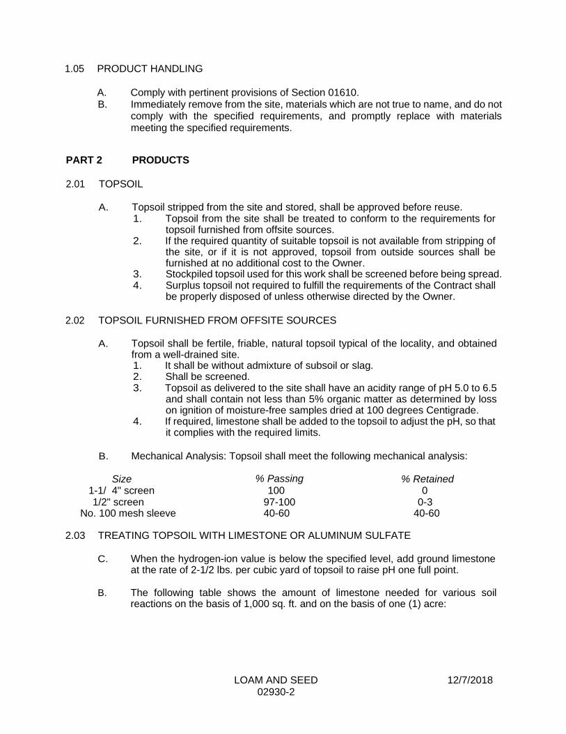
LOAM AND SEED 12/7/2018 02930-2
1.05 PRODUCT HANDLING
A. Comply with pertinent provisions of Section 01610. B. Immediately remove from the site, materials which are not true to name, and do not
comply with the specified requirements, and promptly replace with materials meeting the specified requirements.
PART 2 PRODUCTS
2.01 TOPSOIL
A. Topsoil stripped from the site and stored, shall be approved before reuse.
1. Topsoil from the site shall be treated to conform to the requirements for topsoil furnished from offsite sources.
2. If the required quantity of suitable topsoil is not available from stripping of the site, or if it is not approved, topsoil from outside sources shall be furnished at no additional cost to the Owner.
3. Stockpiled topsoil used for this work shall be screened before being spread. 4. Surplus topsoil not required to fulfill the requirements of the Contract shall
be properly disposed of unless otherwise directed by the Owner.
2.02 TOPSOIL FURNISHED FROM OFFSITE SOURCES
A. Topsoil shall be fertile, friable, natural topsoil typical of the locality, and obtained
from a well-drained site. 1. It shall be without admixture of subsoil or slag. 2. Shall be screened. 3. Topsoil as delivered to the site shall have an acidity range of pH 5.0 to 6.5
and shall contain not less than 5% organic matter as determined by loss on ignition of moisture-free samples dried at 100 degrees Centigrade.
4. If required, limestone shall be added to the topsoil to adjust the pH, so that it complies with the required limits.
B. Mechanical Analysis: Topsoil shall meet the following mechanical analysis:
Size % Passing % Retained
1-1/ 4" screen 100 0 1/2" screen 97-100 0-3
No. 100 mesh sleeve 40-60 40-60
2.03 TREATING TOPSOIL WITH LIMESTONE OR ALUMINUM SULFATE
C. When the hydrogen-ion value is below the specified level, add ground limestone
at the rate of 2-1/2 lbs. per cubic yard of topsoil to raise pH one full point.
B. The following table shows the amount of limestone needed for various soil reactions on the basis of 1,000 sq. ft. and on the basis of one (1) acre:
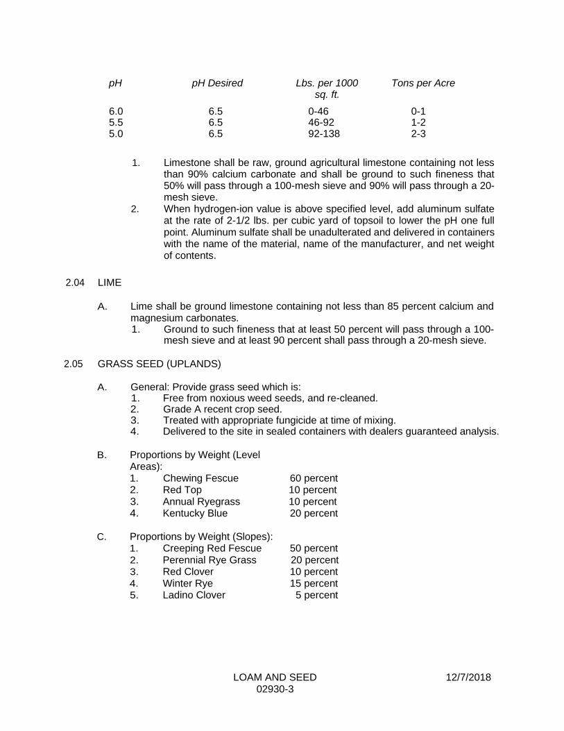
LOAM AND SEED 12/7/2018 02930-3
pH pH Desired Lbs. per 1000 Tons per Acre sq. ft.
6.0 6.5 0-46 0-1 5.5 6.5 46-92 1-2 5.0 6.5 92-138 2-3
1. Limestone shall be raw, ground agricultural limestone containing not less than 90% calcium carbonate and shall be ground to such fineness that 50% will pass through a 100-mesh sieve and 90% will pass through a 20-mesh sieve.
2. When hydrogen-ion value is above specified level, add aluminum sulfate at the rate of 2-1/2 lbs. per cubic yard of topsoil to lower the pH one full point. Aluminum sulfate shall be unadulterated and delivered in containers with the name of the material, name of the manufacturer, and net weight of contents.
2.04 LIME
A. Lime shall be ground limestone containing not less than 85 percent calcium and
magnesium carbonates. 1. Ground to such fineness that at least 50 percent will pass through a 100-
mesh sieve and at least 90 percent shall pass through a 20-mesh sieve.
2.05 GRASS SEED (UPLANDS)
A. General: Provide grass seed which is:
1. Free from noxious weed seeds, and re-cleaned. 2. Grade A recent crop seed. 3. Treated with appropriate fungicide at time of mixing. 4. Delivered to the site in sealed containers with dealers guaranteed analysis.
B. Proportions by Weight (Level
Areas): 1. Chewing Fescue 2. Red Top 3. Annual Ryegrass 4. Kentucky Blue
C. Proportions by Weight (Slopes): 1. Creeping Red Fescue 2. Perennial Rye Grass 3. Red Clover 4. Winter Rye 5. Ladino Clover
60 percent 10 percent 10 percent 20 percent
50 percent 20 percent 10 percent 15 percent
5 percent

LOAM AND SEED 12/7/2018 02930-4
D. Requirements: 1. Seed shall be furnished and delivered premixed in the proportions specified
above. 2. All seed shall comply with State and Federal seed laws. 3. A certificate of compliance with the specifications shall be submitted by the
manufacturer with the shipment of the seed. The certificate shall include the guaranteed percentage of purity, weed content and germination of the seed, net weight and date of shipment.
4. No seed shall be sown until the Contractor has submitted the above mentioned certificate to the Engineer.
2.06. GRASS SEED (WETLANDS)
A. Proportions by Weight 1. Lurid Sedge 2. Fowl Manna Grass 3. Fringed Sedge 4. Woolgrass 5. Other Wetland
Seeds
>10% >10% >10% >10% <60%
B. Germination Minimum 1. Lurid Sedge 2. Fowl Manna Grass 3. Fringed Sedge 4. Wool Grass 5. Other Wetland Seeds
80% 80% 80% 80% 80%
C. Requirements: 1. Grass seed mixture for the compensatory storage areas shall be a fresh,
clean, new crop seed. Seed may be mixed by an approved method on the site or may be mixed by the dealer. All seed shall comply with State and Federal seed laws. If the seed is mixed on the site, each variety shall be delivered in the original containers bearing the dealer's guaranteed analysis. If the seed is mixed by the dealer, the dealer's guaranteed statement of the composition of the mixture and the percentage of purity, weed content, net weight, and germination of each variety shall be provided. No seed shall be sown until the Contractor has submitted the guaranteed statement of the composition to the Engineer.
2. Seed shall be the commercial product of an approved reputable manufacturer and shall be certified to be not more than one (1) year old and shall be composed of the following varieties, the seed mix shall be New England wetmix as manufactured by New England Wetland Plants Inc. Amherst, MA. or approved equal.
3. The application rate shall be one pound per 5,000 square feet. The seed shall be mechanical spread or broadcasted by hand works creating an even distribution. The seed mix shall be sown early spring or late fall for increased germination.
2.07. FERTILIZER

LOAM AND SEED 12/7/2018 02930-5
A. Fertilizer shall be furnished in containers plainly marked with the chemical analysis of the product and showing one of the following compositions by weight.
Constituent 10-6-4 8-6-4 7-7-7
Nitrogen Available Phosphoric Acid Water Soluble Potash
10% min. 6% min. 4% min.
8% min. 6% min. 4% min.
7% min. 7% min. 7% min.
1. Fertilizer shall be stored so that when used it will be dry and free flowing.
2.08. HYDRAULIC SPRAY MACHINE
A. Shall be designed specifically for seed dissemination. B. Shall allow materials to be mixed with water in the machine and kept in an
agitated state to keep materials uniformly suspended in the water. C. Shall be designed to provide equal quantities of required materials over a
particular spraying area. PART 3 EXECUTION
3.01 SURFACE CONDITIONS
A. Examine the areas and conditions under which work of this Section will be
performed. Correct conditions detrimental to timely and proper completion of the Work. Do not proceed until unsatisfactory conditions are corrected.
3.02 APPLICATION
A. Application of Topsoil
1. Topsoil shall be spread to a compacted depth of: a. Two (2) inches for cross country areas. b. Areas to have topsoil applied to them shall be scarified or otherwise
roughened, just prior to the application.
B. Seedbed Preparation
1. Grade areas to be seeded to a smooth uniform grade. 2. Roll, scarify, rake and level as necessary to obtain true, even surfaces 3. Meet existing grades. 4. All seeded areas shall slope to drain. 5. All finish grades shall meet approval before grass seed is sown.
C. Application Rates of Limestone, Aluminum Sulfate, Fertilizer and Seed
1. Limestone or Aluminum Sulfate shall be applied and thoroughly incorporated in the layer of loam or topsoil to adjust the acidity of the material.
2. The rate of application of the limestone will be determined by the pH value. 3. Fertilizer shall be applied at the rate of 20 pounds per 1000 square feet. 4. The seed mixture shall be sown at the rate of 5 pounds per 1000 SF.
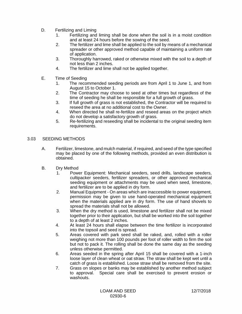
LOAM AND SEED 12/7/2018 02930-6
D. Fertilizing and Liming 1. Fertilizing and liming shall be done when the soil is in a moist condition
and at least 24 hours before the sowing of the seed. 2. The fertilizer and lime shall be applied to the soil by means of a mechanical
spreader or other approved method capable of maintaining a uniform rate of application.
3. Thoroughly harrowed, raked or otherwise mixed with the soil to a depth of not less than 2 inches.
4. The fertilizer and lime shall not be applied together.
E. Time of Seeding 1. The recommended seeding periods are from April 1 to June 1, and from
August 15 to October 1. 2. The Contractor may choose to seed at other times but regardless of the
time of seeding he shall be responsible for a full growth of grass. 3. If full growth of grass is not established, the Contractor will be required to
reseed the area at no additional cost to the Owner. 4. When directed he shall re-fertilize and reseed areas on the project which
do not develop a satisfactory growth of grass. 5. Re-fertilizing and reseeding shall be incidental to the original seeding item
requirements.
3.03 SEEDING METHODS
A. Fertilizer, limestone, and mulch material, if required, and seed of the type specified
may be placed by one of the following methods, provided an even distribution is obtained.
B. Dry Method
1. Power Equipment: Mechanical seeders, seed drills, landscape seeders, cultipacker seeders, fertilizer spreaders, or other approved mechanical seeding equipment or attachments may be used when seed, limestone, and fertilizer are to be applied in dry form.
2. Manual Equipment - On areas which are inaccessible to power equipment, permission may be given to use hand-operated mechanical equipment when the materials applied are in dry form. The use of hand shovels to spread the materials shall not be allowed.
3. When the dry method is used, limestone and fertilizer shall not be mixed together prior to their application, but shall be worked into the soil together to a depth of at least 2 inches.
4. At least 24 hours shall elapse between the time fertilizer is incorporated into the topsoil and seed is spread.
5. Areas covered with park seed shall be raked, and, rolled with a roller weighing not more than 100 pounds per foot of roller width to firm the soil but not to pack it. The rolling shall be done the same day as the seeding unless otherwise permitted.
6. Areas seeded in the spring after April 15 shall be covered with a 1-inch loose layer of clean wheat or oat straw. The straw shall be kept wet until a catch of grass is established. Loose straw shall be removed from the site.
7. Grass on slopes or banks may be established by another method subject to approval. Special care shall be exercised to prevent erosion or washouts.

LOAM AND SEED 12/7/2018 02930-7
C. Hydraulic Method (Hydroseeding) 1. The application of grass seed, fertilizer, limestone, and a suitable mulch, if
approved, may be accomplished through the use of an approved spraying machine.
2. The materials shall be mixed with water in the machine and kept in an agitated state in order for the materials to be uniformly suspended in the water.
3. The spraying equipment shall be so designed that when the solution is sprayed over an area, the resulting deposits of limestone, fertilizer, and grass seed shall be equal to the required rates.
4. Prior to the start of work, the Engineer shall be furnished with a certified statement for approval as to the number of pounds of materials to be used per 100 gallons of water. This statement shall also specify the number of square feet of seeding that can be covered with the quantity of solution in the hydroseeder.
5. The hydraulic seeding and fertilizing machine shall be completely flushed and cleaned each day before seeding is started.
6. If the results of the spray operations are unsatisfactory, the Contractor shall be required to abandon this method and apply the materials in accordance with the dry method.
7. When the hydraulic method is used, compaction or rolling shall be required.
D. Side Slopes Application 1. Roadway side slopes shall be seeded utilizing a hydraulic (hydro-seed)
application process, to place seed and fertilizer simultaneously. 2. A color agent shall also be within the hydraulic mix. 3. Care shall be taken during the application to prevent coverage of poles,
trees, signs, and etc. 3.04 MAINTENANCE
A. The Contractor shall be responsible for the proper care of the seeded areas during
the period when the grass is becoming established. 1. This period shall extend for two months after a successful uniform stand
of grass is produced. 2. The Contractor shall reseed all areas as necessary to obtain a uniform
stand of grass, free from bare spots. 3. Any seeded areas which fail to show a uniform stand of grass shall be
reseeded until all areas are covered 4. Any and all additional seeding shall be at the Contractor's expense. 5. If necessary, barricades of brush or other materials and suitable signs
shall be placed to protect the seeded areas. 6. Any washout which occurs shall be regraded and reseeded at the
Contractor's expense until a good sod is established.
3.05 GUARANTEE PERIOD
A. All seeded areas shall be guaranteed by the Contractor for not less than one (1)
full year from the date of substantial completion.
END OF SECTION

LIVE SOD 4/19/2018 02931-1
SECTION 02931
LIVE SOD
PART 1 GENERAL
1.01 DESCRIPTION
A. Work included: Furnish and place live sod as required by the Contract Documents.
1. Generally the Work consists of placing live sod within the limits shown on the Contract Drawings.
1.02 RELATED WORK
A. Documents affecting work of this Section include, but are not necessarily limited
to, General Conditions, Supplementary Conditions, and Sections in Divisions 1 and 2 of these Specifications.
1. Section 02222 Earthwork for Water Distribution Systems
2. Section 02645 Hydrants
3. Section 02660 Service Connections
4. Section 02930 Loam and Seed
1.03 QUALITY ASSURANCE
A. Use adequate numbers of skilled workmen who are thoroughly trained and experienced in the necessary crafts and who are completely familiar with the specified requirements and the methods needed for proper performance of the work of this Section. 1. Use equipment adequate in size, capacity, and numbers to accomplish the
work in a timely manner. 1.04 SUBMITTALS
A. Comply with pertinent provisions of Section 01300.
B. Product data: Within 30 calendar days after the Contractor has received the
Owner's Notice to Proceed, submit: 1. Materials list of items proposed to be provided under this Section. 2. Manufacturer's specifications and other data needed to prove compliance
with the specified requirements.
1.05 PRODUCT HANDLING
A. Comply with pertinent provisions of Section 01610.

LIVE SOD 4/19/2018 02931-2
B. Immediately remove from the site, materials which are not true to name, and do not comply with the specified requirements, and promptly replace with materials meeting the specified requirements.
PART 2 PRODUCTS
2.01 LIVE SOD
A. Live sod shall meet the requirements of the State, Town and Owner.
1. The Contractor shall furnish and install Sod of similar type and equal to that disturbed during the course of work.
2. Topsoil for Sod Bedding shall be as specified in Section 02930. 3. Stakes for pegging sod shall be made of wood, shall be approximately 1” x
3” and be of sufficient length to securely hold the sod in place. 4. Placement and watering shall meet the requirements of the State, town
and Owner.
PART 3 EXECUTION
3.01 SURFACE CONDITIONS
A. Examine the areas and conditions under which work of this Section will be
performed. Correct conditions detrimental to timely and proper completion of the Work. Do not proceed until unsatisfactory conditions are corrected.
3.02 APPLICATION
A. Obtaining, handling, and storing Sod
1. Special care shall be taken in the transporting, handling, and placement of Sod. a. Sod shall be placed within Twenty-Four (24) hours of being
harvested unless it is stored by approved methods. b. Sod shall be kept moist during transportation, storage, and planting. c. Under no circumstance shall sod be permitted to dry out or freeze. d. Any sod that, in the opinion of the Owner’s representative, appears
to be dried out or will be rejected, shall be removed from the site by the Contractor and shall be replaced with no additional cost to the Owner.
B. Sod bed Preparation
1. Sod bed shall be prepared as specified in Section 02930 except topsoil thickness after compaction shall be minimum Four (4) inches in thickness.
C. Placing Sod 1. Sod bedding shall be sufficiently moistened with water prior to placement. 2. Sod shall be laid evenly so that no spaces or voids are present. 3. Joints between sections of sod shall be staggered. 4. When placing sod along slopes, sections of sod shall be placed across the
slope such that the long sides of the sod sections parallel the slope contours.
5. Sod shall be sufficiently tamped and rolled to eliminate air gaps.

LIVE SOD 4/19/2018 02931-3
6. Sod shall be staked where required. 7. Immediately after placement, sod shall thoroughly watered by the
Contractor. 3.04 MAINTENANCE
A. The Contractor shall be responsible for the proper care of the sodded areas during
the period when the sod is becoming established. 1. Sod shall be watered by the Contractor as required or as directed by the
Owner’s representative. The Contractor shall be responsible for providing all water necessary for maintaining Sod.
2. This period shall extend for two months after a successful uniform stand of grass is produced.
3. The Contractor shall replace any areas of sod that do not become established at no additional cost to the Owner.
4. Any and all additional sodding shall be at the Contractor's expense. 5. If necessary, barricades or other materials and suitable signs shall be
placed to protect the seeded areas. 6. Any washout which occurs shall be repaired and new sod place at the
Contractor's expense until a good, uniform stand of sod is established.
3.05 GUARANTEE PERIOD
A. All areas where sod has been placed shall be guaranteed by the Contractor for
not less than one (1) full year from the date of substantial completion.
END OF SECTION
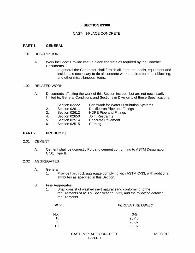
CAST-IN-PLACE CONCRETE 4/19/2018 03300-1
SECTION 03300
CAST-IN-PLACE CONCRETE
PART 1 GENERAL
1.01 DESCRIPTION
A. Work included: Provide cast-in-place concrete as required by the Contract
Documents. 1. In general the Contractor shall furnish all labor, materials, equipment and
incidentals necessary to do all concrete work required for thrust blocking, and other miscellaneous items.
1.02 RELATED WORK
A. Documents affecting the work of this Section include, but are not necessarily
limited to, General Conditions and Sections in Division 1 of these Specifications.
1. Section 02222 Earthwork for Water Distribution Systems 2. Section 02611 Ductile Iron Pipe and Fittings 3. Section 02612 HDPE Pipe and Fittings 4. Section 02650 Joint Restraints 5. Section 02514 Concrete Pavement 6. Section 02515 Curbing
PART 2 PRODUCTS
2.01 CEMENT
A. Cement shall be domestic Portland cement conforming to ASTM Designation
Cl50, Type II.
2.02 AGGREGATES
A. General
1. Provide hard rock aggregate complying with ASTM C-33, with additional attributes as specified in this Section.
B. Fine Aggregates
1. Shall consist of washed inert natural sand conforming to the requirements of ASTM Specification C-33, and the following detailed requirements.
SIEVE PERCENT RETAINED
No. 4 16 50 100
0-5 25-40 70-87 93-97
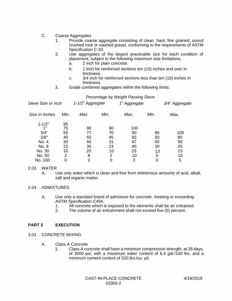
CAST-IN-PLACE CONCRETE 4/19/2018 03300-2
C. Coarse Aggregates 1. Provide coarse aggregate consisting of clean, hard, fine grained, sound
crushed rock or washed gravel, conforming to the requirements of ASTM Specification C-33.
2. Use aggregates of the largest practicable size for each condition of placement, subject to the following maximum size limitations. a. 2 inch for plain concrete.
b. 1 inch for reinforced sections ten (10) inches and over in thickness.
c. 3/4 inch for reinforced sections less than ten (10) inches in thickness.
3. Grade combined aggregates within the following limits:
Percentage by Weight Passing Sieve
Sieve Size or Inch 1-1/2" Aggregate 1" Aggregate 3/4" Aggregate
Size in Inches
1-1/2"
Min.
95
Max. Min. Max. Min. Max.
1" 75 90 90 100 3/4" 55 77 70 90 90 100 3/8" 40 55 45 65 60 80
No. 4 30 40 31 47 40 60 No. 8 22 35 23 40 30 45
No. 30 10 20 10 23 13 23 No. 50 2 8 2 10 5 15
No. 100 0 3 0 3 0 5
2.03 WATER A. Use only water which is clean and free from deleterious amounts of acid, alkali,
salt and organic matter.
2.04 ADMIXTURES
A. Use only a standard brand of admixture for concrete, meeting or exceeding
ASTM Specification C494. 1. All concrete which is exposed to the elements shall be air entrained. 2. The volume of air entrainment shall not exceed five (5) percent.
PART 3 EXECUTION
3.01 CONCRETE MIXING
A. Class A Concrete
1. Class A concrete shall have a minimum compressive strength, at 28 days, of 3000 psi, with a maximum water content of 6.4 gal./100 lbs. and a minimum cement content of 520 lbs./cu. yd.
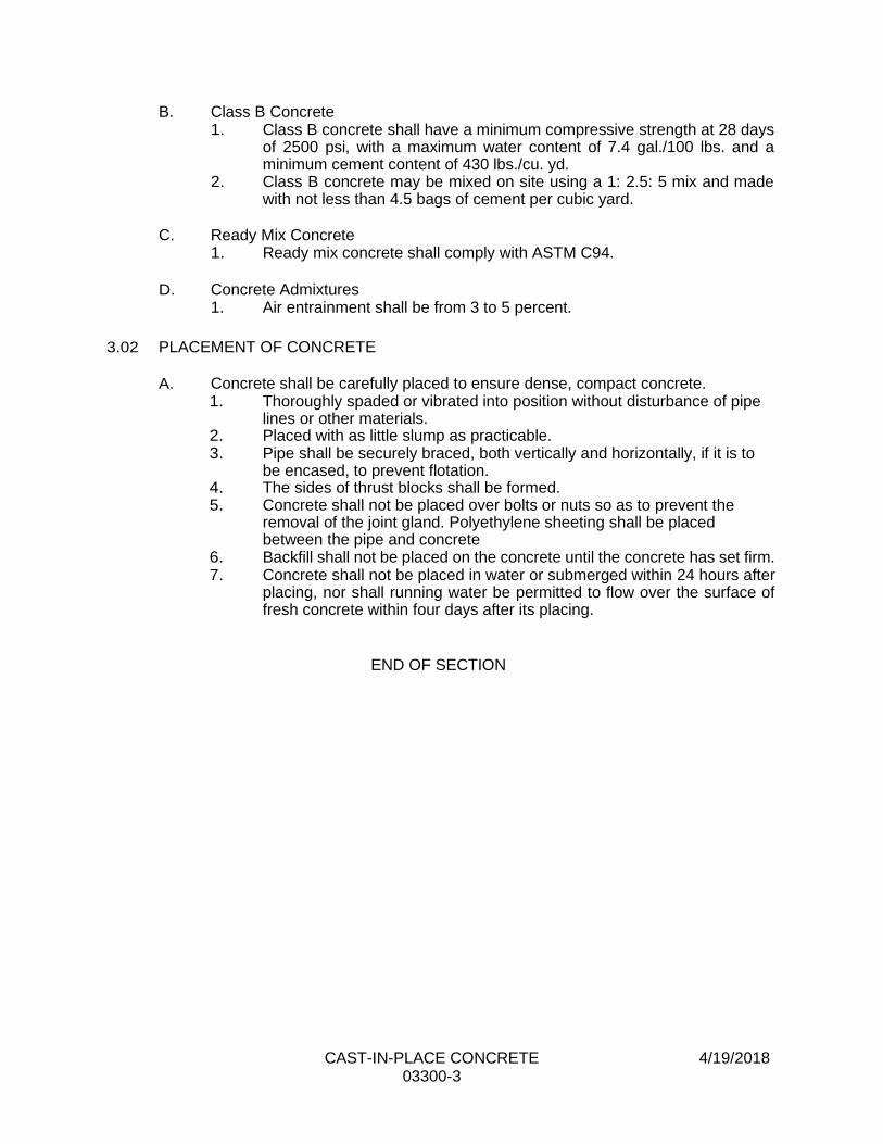
CAST-IN-PLACE CONCRETE 4/19/2018 03300-3
B. Class B Concrete 1. Class B concrete shall have a minimum compressive strength at 28 days
of 2500 psi, with a maximum water content of 7.4 gal./100 lbs. and a minimum cement content of 430 lbs./cu. yd.
2. Class B concrete may be mixed on site using a 1: 2.5: 5 mix and made with not less than 4.5 bags of cement per cubic yard.
C. Ready Mix Concrete
1. Ready mix concrete shall comply with ASTM C94.
D. Concrete Admixtures
1. Air entrainment shall be from 3 to 5 percent.
3.02 PLACEMENT OF CONCRETE
A. Concrete shall be carefully placed to ensure dense, compact concrete. 1. Thoroughly spaded or vibrated into position without disturbance of pipe
lines or other materials. 2. Placed with as little slump as practicable. 3. Pipe shall be securely braced, both vertically and horizontally, if it is to
be encased, to prevent flotation. 4. The sides of thrust blocks shall be formed. 5. Concrete shall not be placed over bolts or nuts so as to prevent the
removal of the joint gland. Polyethylene sheeting shall be placed between the pipe and concrete
6. Backfill shall not be placed on the concrete until the concrete has set firm. 7. Concrete shall not be placed in water or submerged within 24 hours after
placing, nor shall running water be permitted to flow over the surface of fresh concrete within four days after its placing.
END OF SECTION