Embed Size (px)
Citation preview

Exterior
Technical Manual

Technical Document of C.A.T 3 Ventilated Façade System
Technical Dep. Wandegar Wandegar_2001_S.L.U__-_P.I_Mabesa_Camí_Foies_Ferraes_Nave_13._
Phone_ +34 964_363_721__Fax_ +34 964_386_720__CP:_12110__L'Alcora_(Castellón)_
INTRODUCTION
The façade is the outdoor and main wall of a building, isolating the
perimeter of outdoor environment. The main characteristic of ventilated
façades is the air chamber, divided by two parts, the indoor one resolved by
the insulation and sealing, and the outdoor one, which form an air chamber,
ensuring a continuous ventilation along the whole façade surface. It permits
isolate the cold in winter and warm in summer, achieving energetic saves
up to 30%. Outdoor cladding walls could be of many kind of materials such
ceramic, natural stone, composites, etc. Rediwa CAT 3 system is a visible
anchoring that supports and retains the ceramic by its corners. Furthermore,
the system is complemented by the fixing longitudinal of an elastic-
chemical adhesive of ceramic to the vertical profiles, increasing the safety
and avoiding any vibration because of wind, expansion, etc.
USING TERMS
Rediwa CAT 3 System has been developed to be installed such ventilated
cladding wall with ceramic tiles, point-fixed with stainless steel clamps and
longitudinal beads of adhesive to the metallic structure. This system does
not contribute to building stability.
Wandegar or any other specialized company approved by us should install
the system, being possible the technical assistance of Wandegar. We
reserve the inspection right of checking any installation of the system
described in this document, whether or not executed by Wandegar.
The installer company will ensure that installation will be executed
according to conditions exposed in this document and tolerating the
observations made by the Technical Department of Wandegar.

TECHNICAL DOCUMENT OF VENTILATED FAÇADE SYSTEM
This Technical Document has been created by the Technical Department of
Wandegar following the specifications in the actual normative. The system
metallic substructure and its anchorages on the wall (vertical profiles and
brackets) are exactly the same than the ones described in DIT 529/09 that
issue the Eduardo Torroja Sciences Construction Institute, so Wandegar
extends this structure description to this document.

1. OBJECT
The named system Rediwa CAT 3 developed to install ventilated façade in
new building or restoration, composed by ceramic tiles fixed to the
aluminium framework with chemical and mechanical anchors.
The framework is based in vertical profiles, fixations and its corresponding
anchors. They were developed to be installed on regular and vertical walls.
These walls can be done of concrete, bricks or metallic structure.
Anyway, anchors should be defined in the ventilated façade technical
project depending the support and loadings to transmit.
2. DESCRIPTION OF THE SYSTEM
The Rediwa CAT 3 system is composed by:
- Vertical aluminium profiles anchored to wall support with brackets
and the necessaries anchors. These profiles will be coincident with
the vertical joints.
- Stainless steel clips AISI 304
- Single component elastic putty, based on polymer MS.
Fig. 1: Detail of Rediwa CAT 3 system

3. COMPONENTS AND MATERIALS
3.1 Coverings
This system has been developed to use it with ceramic coverings.
Wandegar is not a ceramic producer, so we do not guarantee its quality.
3.2 Elastic adhesive putty.
Monocomponent elastic adhesive putty, based on polymer MS of fast
drying with moisture in air.
Properties:
- Single component, easy application between +5 and +50 ºC
- It adheres without primmer
- Neutral. It doesn’t corrode metals neither alkaline substrates attacks.
- It stays flexible from -40 to +90ºC
- Very high resistance to UV.
- Good adherence on wet surfaces.
Characteristics of non-dried adhesive
Aspect Homogeneous creamy paste
Take off (NF P 85501): Null
Tack free (ASTM C-679-71) 10-15 minutes
Dry speed to A23ºC and 55% air
moisture
2-3 mm/day
Volume losses (DIN 52451) Inappreciable
Skin formation (BS 5889 Ap A) 20-40 minutes
Ignition temperature (DIN 51794) 460 ºC
Application temperature +5 to +50ºC
Characteristics of dried adhesive (4 weeks to 23ºC and 55% air moisture)
Aspect Similar to rubber
Shore Hardness A (DIN 53505) 40±3
Elastic Module 100% (DIN 53504) 0.8-1.1 MPa
Traction Resistance (DIN 53504) 1.8-2.4 MPa
Breaking Elongation (DIN 53504) 350-450 %
Joint Movement 25%
Temperature Resistance -40 to +90ºC
UV Resistance Very good

3.3 Clips
The anchoring clips are made in stainless steel AISI 304. The visible clips
are lacquered to same colour than ceramic. These clamps are fixed to
vertical framework with auto drilling screws A2 4.5x19mm coincident with
vertical opened joints, so installation and replacement is very easy.
Fig. 2 CAT 3 System Visible clip
Mechanical Properties:
Creep Resistance 310 MPa (45 KSI)
Maximum Resistance 620 MPa (90KSI)
Elongation 30% (in 50mm)
Area Reduction 40%
Modulus of Elasticity 200 Gpa (29000 KSI)

Physics Properties:
Density 7.8 g/cm3 (0.28 lb/in3)
Chemical Properties:
0.08% C min
2.00 % Mn
1.00 % Si
18.0 – 20.0 % Cr
8.0 – 10.5 % Ni
0.045 % P
0.03 % S
3.4 Substructure
3.4.1 Materials
The vertical profiles and brackets are manufactured with extruded
aluminium of magnesium-silicon alloy EN-AW 6063 with treatment T5.
Phisical and mechanical characteristics are indicated on this table:
Density (kg/dm3) 2.7
Modulus of Elasticity (MPa) 69500
Poisson Coefficient 0.33
Maximum tension admissible (MPa) (4) ≥ 175
Elastic Limit Rp 0.2 (MPa) (4) ≥ 130
Elongation 8
Thermal Expansion Coefficient (k-1) (20
to 100ºC)
23’6 . 10-6
3.5.2 BRACKETS
There exist two types:
- Sustaining brackets, which support and transmit to the concrete
structure weight and wind burdens. They’re usually fixed to slabs.
- Retaining brackets, which they just transmit the horizontal wind
burdens. They’re fixed to wall support.
All these brackets are 3mm thickness.

You can check the geometric characteristics of the brackets in the
following table:
Characteristics Length sides 70x50 Length sides 90x60
Weight (kg/m) 0.8 1.15
Area (mm2) 351 441
Perimeter (mm) 240 300
Turning radius Xc (mm) 22.68 29.37
Turning radius Yc (mm) 14.99 17.86
Moment of Inertia Ixx (cm4) 18.05 38.04
Moment of Inertia Iyy (cm4) 7.88 14.07
Standard Bracket 70x50x115
Standard Corner Bracket 70x180x80

3.5.3 Vertical Profile
There exist four different standard vertical profiles. Physical and
mechanical characteristics are indicated on this table. Measurements are
indicated on fig. 3. Dimensional and shape tolerances are agree with Norm
UNE EN 755-9. To special applications, these profiles could be another
one non-standardized according to the needs.
Tube profile 40x40 Column Vertical Profile 80x40
T Vertical Profile 60 x 80 Column Vertical Profile 80x64
3.5.4 Fasteners
The fasteners to join profiles together and also to the brackets are
manufactured with stainless steel on A2 or A4 alloy with the measurements
and mechanical properties according to this table.


3.5.5 Anchorages to support
Type, position and number of anchorages of the brackets to the wall
support will depend according to the support material and the efforts
transmitted to it, being reflected on the previous ventilated façade project.
The standard anchorages to the slabs are the mechanical plugs A2 M8x75
with these main characteristics:
- Traction Resistance: 561 kg
- Shear loading: 513 kg
4. INSTALLATION
4.1 VERTICAL PROFILES INSTALLATION
This structure is installed on the support with the brackets and
necessary anchorages.
The vertical profiles will be installed coincident with the vertical joints.

4.2 PORCELAIN INSTALLATION
To install the porcelain, you have to fix to the vertical profile an initial
clamp with the auto-drilling screw 4.2x19 on the bottom side of the
porcelain. Then, you have to apply a vertical putty string on the vertical
profile, and then, when you install the porcelain, this putty will also join the
porcelain to the profile. This putty provides a higher safety and avoids
porcelain movements. Then non-leaving the porcelain, insert the standard
clamp on the top grooves and screw to the vertical profile. Then, you can
continue fixing all the horizontal line with porcelain using the initial
clamps and following the process. It’s advisable to start from the bottom to
the top.
Apply the putty string
Nails of the Visible Clamp

5. TESTS IN OUTSIDE LABORATORIES
6. STRUCTURAL CALCULATION
The action on the ventilated façade system will be calculated according to
CTE DBSE-AE related to actions on edification.
For the system calculation, it will be considered that porcelain should
support wind loadings (pressure and suction) and transmit them, with its
own weight and through the structure and anchorages to the support.
To buildings up to 30m high and to limitations according to CTE-DB-SE-
AE related to wind action, these will be determined according to
established in that Basic Document (DB), that talks about the building high,
size and position of the porcelain.

For greater heights, or special wind loading areas, it will be necessary to
make a specific study to determine the wind actions and Aeolian
pressure/suction coefficients.

INTRODUCTION
A ventilated facade is defined as the exterior and the main facing of a building, so, it
insulates the perimeter from exterior environment. A ventilated façade is characterized
mainly because it is a enclosure with an air chamber, separated by two skins, the
internal one resolves the insulation and the sealing, and the external, whose main
mission is to create the air chamber, ensures a continuous ventilation all along the
surface of the façade. That permits insulation from cold in winter and warm in summer,
getting energy savings up to 30%. The external facing is open to be resolved with a lot
of materials: ceramic tiles, natural stone, phenolic panel, etc. The Rediwa CAT 7 system
has been specially designed to be used on thickness ceramic tile coating (maximum 7
mm).
TERMS OF USE
The Rediwa CAT 7 System described on the present document has been designed for
coating in ventilated facades by using a ceramic material with a thickness lower than
7mm fixed to a metallic substructure by using a chemical fixation. The installation of
this System must be carried out by WANDEGAR 2001 S.L. (onwards Wandegar) or
other installators recognized by the own company, doing possible the technical
assistance by Wandegar. Wandegar reserves the right to inspect the works executed by
using the system described on this document, whether or not have been executed by the
company.
The installation company must ensure that the system implementation work is carried
out under the conditions and fields described by the present Technical Document and
respecting the comments of the Technical Department of Wandegar.
TECHNICAL DOCUMENT
The present technical document has been written by the Technical Department of
Wandegar and specified in accordance with the current applicable regulations. The
metallic substructure of the system and their supporting wall fixings (vertical profiles
and anchors) are exactly the same as those described in the DIT 525/09 of the Institute
of Construction Science Eduardo Torroja. Wandegar extends the description of the
substructure described in the DIT to this document. The system was tested by the
DRAFT ETAG 034 - EOTA (European Organisation for Technical Approvals) in the
laboratories of APPLUS+ to load pressure and suction obtaining highly satisfactory
results.
L´Alcora (Castellón), 7th of July 2010
TECHNICAL DEPARMENT of WANDEGAR
Ventilated Façade System - Technical Document
Rediwa CAT 7 System
Technical Department of Wandegar Wandegar 2001 S.L. - P.I Mabesa Camí Foies Ferraes Nave 13.
Tel 964 363 721 Fax 964 386 720 C.P: 12110 L'Alcora (Castellón) [email protected]
TECHNICAL DOCUMENT OF VENTILATED FACADE SYSTEM
1. OBJECT The ceramic fixing system Rediwa C.A.T 7
developed by Wandegar for slim ceramic tiles
(below 8mm thickness) as the one manufactured
by THE SIZE consists basically in a chemical-
elastic longitudinal fixing of the ceramic over
vertical profiles besides a mechanical support
where the tile weight rests.
2. PRINCIPLE AND SYSTEM
DESCRIPTION The REDIWA CAT 7 system of ventilated façades
is composed by:
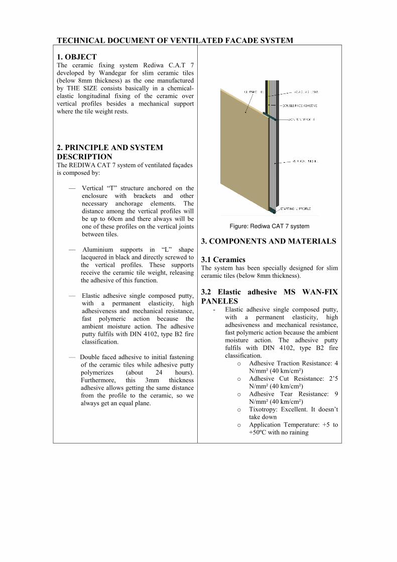
— Vertical “T” structure anchored on the
enclosure with brackets and other
necessary anchorage elements. The
distance among the vertical profiles will
be up to 60cm and there always will be
one of these profiles on the vertical joints
between tiles.
— Aluminium supports in “L” shape
lacquered in black and directly screwed to
the vertical profiles. These supports
receive the ceramic tile weight, releasing
the adhesive of this function.
— Elastic adhesive single composed putty,
with a permanent elasticity, high
adhesiveness and mechanical resistance,
fast polymeric action because the
ambient moisture action. The adhesive
putty fulfils with DIN 4102, type B2 fire
classification.
— Double faced adhesive to initial fastening
of the ceramic tiles while adhesive putty
polymerizes (about 24 hours).
Furthermore, this 3mm thickness
adhesive allows getting the same distance
from the profile to the ceramic, so we
always get an equal plane.
Figure: Rediwa CAT 7 system
3. COMPONENTS AND MATERIALS
3.1 Ceramics The system has been specially designed for slim
ceramic tiles (below 8mm thickness).
3.2 Elastic adhesive MS WAN-FIX
PANELES - Elastic adhesive single composed putty,
with a permanent elasticity, high
adhesiveness and mechanical resistance,
fast polymeric action because the ambient
moisture action. The adhesive putty
fulfils with DIN 4102, type B2 fire
classification.
o Adhesive Traction Resistance: 4
N/mm² (40 km/cm²)
o Adhesive Cut Resistance: 2’5
N/mm² (40 km/cm²)
o Adhesive Tear Resistance: 9
N/mm² (40 km/cm²)
o Tixotropy: Excellent. It doesn’t
take down
o Application Temperature: +5 to
+50ºC with no raining

3.3 Primer Primary framework primed to improve the
adherence of the putty with a chemical product
made with alcohols and polyurethane resin. Color: Colorless.
Solid Contents: 5%
Inflammation point (DIN
51755):
-14ºC
Solvents: Acetone, toluene, xylene
Treatment of the Board: The surfaces should be dry, firm
and free of dust, mud, oil or
grease, etc. After cleaning with
ethanol is recommended.
Work Technique: Implement, preferably to brush, a
thin, continuous layer on the walls
of the Board previously treated,
leaving dry approximately an hour
before applying the sealant.
Drying time: Approximately 30 minutes at 23
ºc.
PRIMER C-29 It is flammable. Do not smoke or use unprotected
flame during its implementation. The work area must be well
ventilated.
PRIMER C-29 It is dangerous by inhalation. Avoid contact with
skin or eyes. Wear gloves, and before eating or smoking, wash
your hands with an industrial detergent..
3.4 Double faced adhesive Double faced adhesive to initial fastening of the
ceramic piece while the adhesive putty
polymerizes (about 24 hours). Furthermore, this
3mm thickness adhesive allows getting the same
distance from the profile to the ceramic, so we
always get an equal plane.
3.5 Structure
3.5.1 Materials All the aluminium profiles (vertical, “L” and “U”)
and the brackets are extruded in EN AW 6063
aluminium.
Physical and mechanical characteristics are listed
in the table: Density (kg/dm3) 2,70
Elastic Module (MPa) 69 500
Poisson Coefficient 0,33
Maximum allowed stress (MPa)
(4))
≥ 175
Elastic Limit Rp 0,2 (MPa) (4) ≥ 130
Elongation (% (4) 8
Expansion Thermal Coefficient
( K-1)
(20 a 100 ºC)
23,6 .10-6
3.5.2 Brackets Special aluminium pieces with “L” shape and
3mm thickness fixed to the walls of the building to
connect the ventilated façade substructure with the
building’s framework. There are two kinds:
• Load, which are the responsible of supporting
and transmitting to the wall support the whole
weight and wind. These brackets are placed in the
building structural elements.
• Retention, its function is to support and pass the
wall support horizontal loads generated by the
wind; they are placed on the wall support.
All the Brackets have a thickness of 3mm.
The geometric characteristics of most frequent use
brackets are listed in following table: Characteristics Wing length
70x50
Wing length
90x60
Weight (kg / m) 0,80 1,15
Area (mm2) 351 441
Perimeter (mm) 240 300
Turning Radius Xc (mm) 22,68 29,37
Turning Radius Yc (mm) 14,99 17,86
Inertial Moment IXX(cm4) 18,05 38,04
Inertial Moment Iyy (cm4) 7,88 14,07
Standard Bracket
(Front elevation, side and section)
Corner Bracket
(Front elevation, side and section) Designation Detalle
Load Bracket 90 x
60 x 175
Retention Bracket
90 x 60 x 110
Standard Bracket 80
x 40 x 140
Standard Bracket 80
x 40 x 100
Load Bracket 70 x
50 x 150
Retention Bracket
50 x 50 x 120
Standard Bracket
100 x 85 x 200

3.5.3 Vertical profiles Vertical structure anchored to the enclosure with the
brackets. The distance among the vertical profiles
will be up to 60cm and there always will be one of
these profiles on the vertical joints between tiles.
For special applications there are other vertical
profiles not standardized. Characteristics Profile �
40x40
Profile T
60 x 80
Profile
45x 43
Profile
64x45
Weight (kg/m) 0,85 0,90 1,09 1,52
Area (mm2) 304 333,53 406,84 563,37
Minimum
thickness (mm)
1,5 2,5 3 3
Perimeter (mm) 160 320 469 571
Turning Radius
Xc (mm)
15,73 19,36 18,12 26,91
Turning Radius
Yc (mm)
15,73 17,13 20,91 20,63
Inertial Moment
IXX (cm4)
5,71 11,50 13,37 23,97
Inertial Moment
Iyy (cm4)
5,71 10,67 17,80 40,80
Profile �
40x40
Profile T
60 x 80
Profile 45x 43
Profile 64x45
3.5.4 Anchors Anchorages used will be always in A2 or A4
steel alloy:
3.5.5 Load Anchors The type, position and number of anchorages for
attaching the brackets to the wall support will be
calculated depending on the material of the wall
and the loads calculation. This will be reflected in
the technical project of the ventilated facade.
Standard anchor
4.SYSTEM PROCESS INSTALLATION
4.1 Primary framework installation
Vertical “T” structure anchored on the enclosure
with brackets and other necessary anchorage
elements. The distance among the vertical
profiles will be up to 60cm and there always will
be one of these profiles on the vertical joints.

4.2 “L” Profile installation “L” profile installation that serves as a support to
the initial tiles on the bottom of the façade. This
horizontal profile also will serve to get the façade
perfect levelled.
4.3 Vertical profiles cleaning and
primering The vertical profile cleaning is achieved using a
cloth to eliminate dust and aluminium chips. Later,
we primer these profiles to improve the adherence
of the putty.
4.4 Double faced adhesive and elastic-
adhesive putty application
MS WAN-FIX PANELES
Central vertical profile
Lateral vertical profile
MS WAN-FIX PANELES
Double Shield Adhesive
4.5 Ceramic tile installation
L´Alcora (Castellón), 7th of July 2010,
TECHNICAL DEPARMENT of WANDEGAR

www.neolith.co.za