Embed Size (px)
Citation preview
External control panel
Emotron FDU/VFX 2.0
Instruction manual
English
CG Drives & Automation 01-5928-01r1 1
External Control Panel for Emotron FDU 2.0 and VFX 2.0
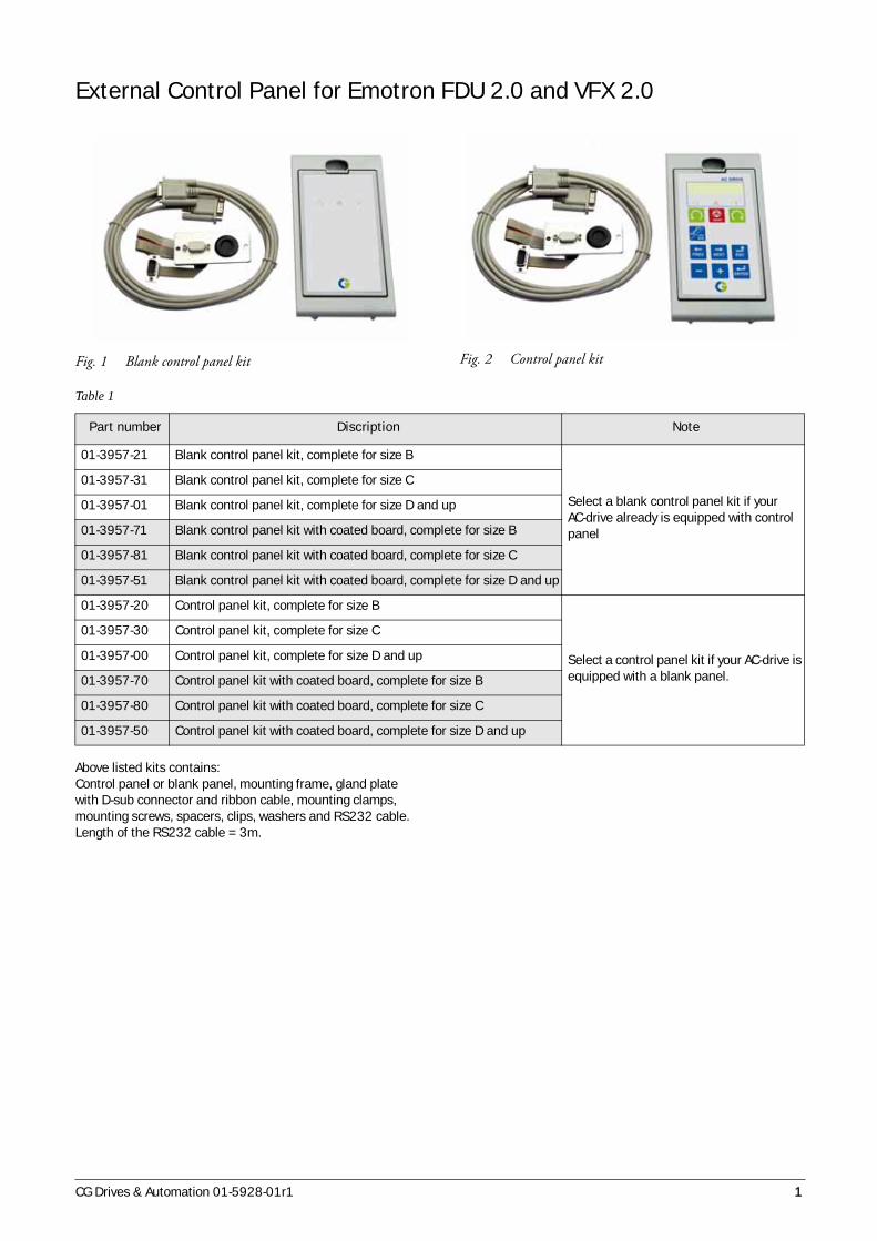
Fig. 1 Blank control panel kit Fig. 2 Control panel kit
Above listed kits contains:Control panel or blank panel, mounting frame, gland plate with D-sub connector and ribbon cable, mounting clamps, mounting screws, spacers, clips, washers and RS232 cable. Length of the RS232 cable = 3m.
Table 1
Part number Discription Note
01-3957-21 Blank control panel kit, complete for size B
Select a blank control panel kit if your AC-drive already is equipped with control panel
01-3957-31 Blank control panel kit, complete for size C
01-3957-01 Blank control panel kit, complete for size D and up
01-3957-71 Blank control panel kit with coated board, complete for size B
01-3957-81 Blank control panel kit with coated board, complete for size C
01-3957-51 Blank control panel kit with coated board, complete for size D and up
01-3957-20 Control panel kit, complete for size B
Select a control panel kit if your AC-drive is equipped with a blank panel.
01-3957-30 Control panel kit, complete for size C
01-3957-00 Control panel kit, complete for size D and up
01-3957-70 Control panel kit with coated board, complete for size B
01-3957-80 Control panel kit with coated board, complete for size C
01-3957-50 Control panel kit with coated board, complete for size D and up
2 CG Drives & Automation 01-5928-01r1
Mounting the control panel in a cabinet door or external panel
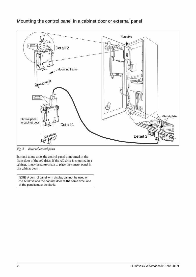
Fig. 3 External control panel
In stand-alone units the control panel is mounted in the front door of the AC drive. If the AC drive is mounted in a cabinet, it may be appropriate to place the control panel in the cabinet door.
Detail 2
Detail 1
Detail 3
Flatcable
Mounting frame
Control panelin cabinet door
Gland plate
NOTE: A control panel with display can not be used on the AC drive and the cabinet door at the same time, one of the panels must be blank.
CG Drives & Automation 01-5928-01r1 3
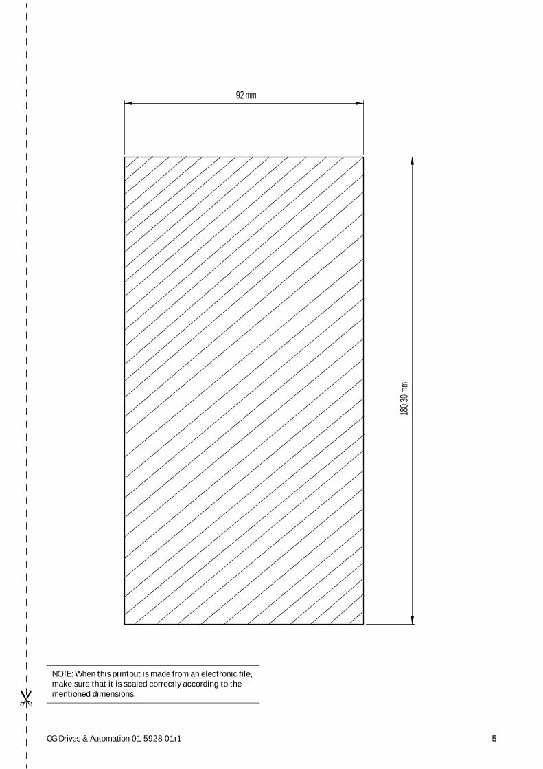
Mounting instructions1. Punch/drill hole in the cabinet door according to the
template on the last page.
2. Place the mounting frame into the hole from the outside of the cabinet door.
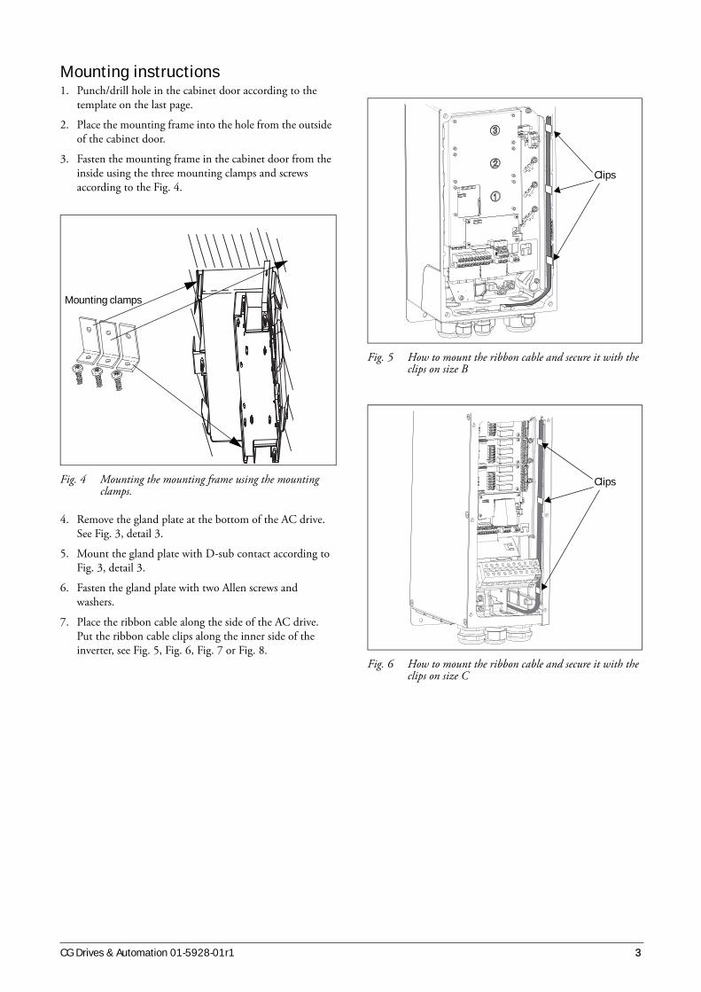
3. Fasten the mounting frame in the cabinet door from the inside using the three mounting clamps and screws according to the Fig. 4.
Fig. 4 Mounting the mounting frame using the mounting clamps.
4. Remove the gland plate at the bottom of the AC drive. See Fig. 3, detail 3.
5. Mount the gland plate with D-sub contact according to Fig. 3, detail 3.
6. Fasten the gland plate with two Allen screws and washers.
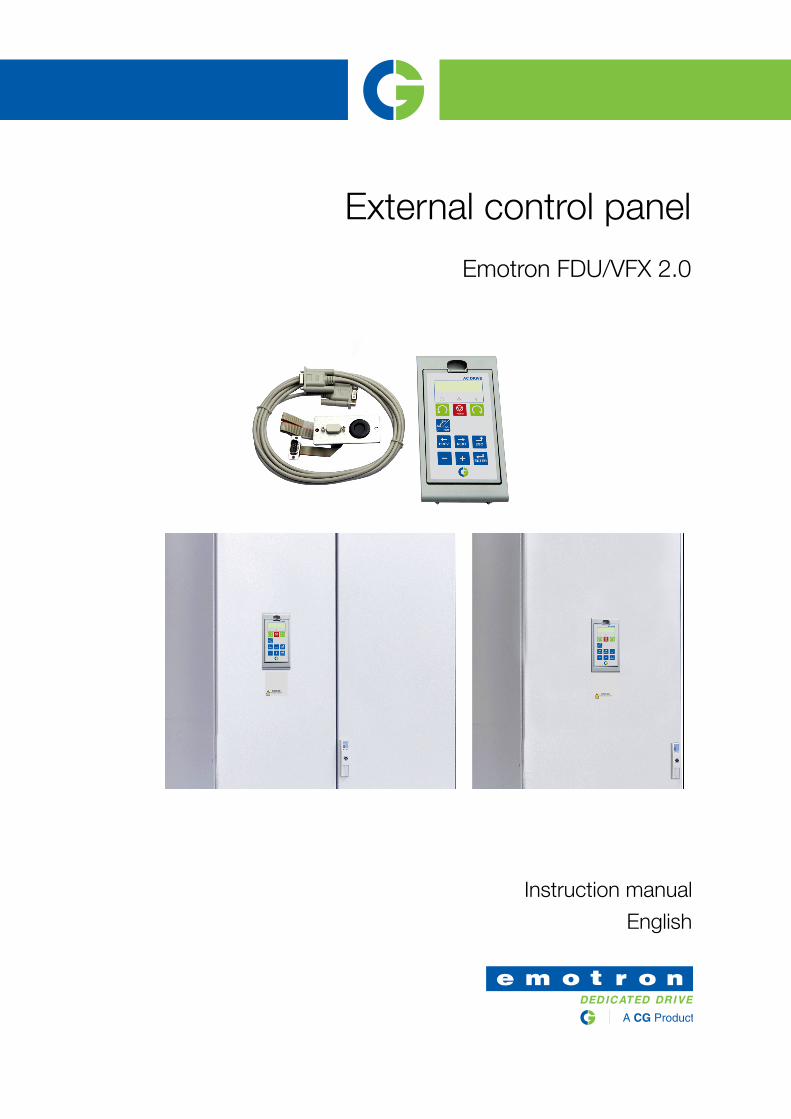
7. Place the ribbon cable along the side of the AC drive. Put the ribbon cable clips along the inner side of the inverter, see Fig. 5, Fig. 6, Fig. 7 or Fig. 8.
Fig. 5 How to mount the ribbon cable and secure it with the clips on size B
Fig. 6 How to mount the ribbon cable and secure it with the clips on size C
Mounting clamps
Clips
Clips

4 CG Drives & Automation 01-5928-01r1
Fig. 7 How to mount the ribbon cable and secure it with the clips on size D.
Fig. 8 How to mount the ribbon cable and secure it with the clips on size E and F
8. Mount the spacers and washers on the female D-sub contact on the back of the control panel in the AC drive door. See Fig. 3, detail 2.
9. Connect the ribbon cable, male connector, according to Fig. 3, detail 2. and fasten it with 2 screws.
10. Connect the standard RS232 cable, female connector, between the gland plate in the bottom of the AC drive and the back plane of the control panel in the cabinet door according to Fig. 3, detail 1.
11. Snap a blank panel into the frame on the AC drive.
12. Snap the control panel into the mounting frame in the cabinet door.
Clips
Clips
CG Drives & Automation 01-5928-01r1 5
NOTE: When this printout is made from an electronic file, make sure that it is scaled correctly according to the mentioned dimensions.
92 mm
180,3
0 mm

6 CG Drives & Automation 01-5928-01r1

CG
Drive
s &
Auto
matio
n, 0
1-5
928-0
1r1
2015
-05
-20
CG Drives & Automation Sweden ABMörsaregatan 12
Box 222 25
SE-250 24 Helsingborg
Sweden
T +46 42 16 99 00
F +46 42 16 99 49
www.emotron.com/www.cgglobal.com