Embed Size (px)
Citation preview

SI RINSTITUTE FOR SYSTEMS RESEARCH
Sponsored bythe National Science FoundationEngineering Research Center Program,the University of Maryland,Harvard University,and Industry
TECHNICAL RESEARCH REPORT
Extracting Alternative Machining Features: Al Algorithmic Approach
by W.C. Regli, S.K. Gupta, D.S. Nau
T.R. 94-55

Extracting Alternative Machining Features: An AlgorithmicApproach
William C. RegliDepartment of Computer Science and
Institute for Systems ResearchUniversity of MarylandCollege Park, MD 20742
Satyandra K. GuptaMechanical Engineering Department and
Institute for Systems ResearchUniversity of MarylandCollege Park, MD 20742
Dana S. NauDepartment of Computer Science,
Institute for Advanced Computer Studies andInstitute for Systems Research
University of MarylandCollege Park, MD 20742
Corresponding Author: William C. RegliDepartment of Computer Science andInstitute for Systems ResearchUniversity of MarylandCollege Park, MD 20742

Extracting Alternative Machining Features: An Algorithmic
Approach
William C. Regli�
Department of Computer Science and
Institute for Systems Research
University of Maryland
Satyandra K. Gupta
Mechanical Engineering Department and
Institute for Systems Research
University of Maryland
Dana S. Nau
Department of Computer Science,
Institute for Advanced Computer Studies and
Institute for Systems Research
University of Maryland
Abstract
Automated recognition of features from CAD models has been attempted for a wide rangeof application domains. In this paper we address the problem of representing and recognizingthe complete class of features in alternative interpretations for a given design.
We present a methodology for recognizing a class of machinable features and addressing thecomputational problems posed by the existence of feature-based alternatives. Our approach ad-dresses a class of volumetric features that describe material removal volumes made by operationson 3-axis vertical machining centers including: drilling, pocket-milling, slot-milling, face-milling,chamfering, �lleting, and blended surfaces.
This approach recognizes intersecting features and is complete over all features in our class;i.e., for any given part, the algorithm produces a set containing all features in our class thatcorrespond to possible operations for machining that part. This property is of particular signif-icance in applications where consideration of di�erent manufacturing alternatives is crucial.
This approach employs a class of machinable features expressible as MRSEVs (a STEP-basedlibrary of machining features). An instance of this methodology has been implemented usingthe ACIS solid modeler and the National Institutes of Health C++ class library (NIHCL).
1 Introduction
In general, there may be many di�erent ways to manufacture a given design. It is becoming in-creasingly evident that consideration of these manufacturing alternatives is crucial for tasks such asmanufacturability analysis and process planning. How easy it is to manufacture a design, or whetherit will be possible to meet the design speci�cations at all, may depend on which manufacturingalternative is chosen.
In the speci�c case of machining, di�erent ways to manufacture a design for a machinable partcorrespond to di�erent interpretations of the design as sets of machining features. Ideally, we wouldlike a feature recognition system to �nd the machining features corresponding to all of the di�erentways in which the design could be machined. However, for complex parts, it usually is not feasible
simply to enumerate all of the feature instances, because the number of them can be very large, oreven in�nite|and in most cases, very few of the potential feature instances for a part will makepractical manufacturing sense.
To address this need, this paper presents a methodology for recognizing a class of \well-behaved"machinable features that are useful for manufacturing. These features could then be used asinput to a variety of possible applications, such as manufacturability analysis, automated redesign,process planning, or part-code generation for group technology. Our approach has the followingcharacteristics:
1. It is complete over all features in our class; i.e., for any given part, the set of features producedby the algorithm contains all features in our class that correspond to machining operationson that part, regardless of how complicated the intersections are among those features.
2. It is capable of identifying and eliminating some machining features as inaccessible. Thefeatures eliminated are guaranteed to be inaccessible in all potential operation plans for thegiven design.
3. Applications such as manufacturability analysis and automated redesign require features thatcorrespond directly to manufacturing operations. The class of machinable features we em-ploy are expressible as MRSEVs (a PDES/STEP-based library of machining features) [23].MRSEVs are de�nable using EXPRESS (the PDES information modeling language) and asPDES form features. By employing a set of features based on a standard interchange formatsuch as STEP, we are attempting to use an independently de�ned feature class and addressa domain of machinable parts of interest to a large community.
4. The algorithms have been implemented and are being incorporated as part of the IMACS1
design critiquing system under development at the University of Maryland's Institute forSystems Research.
Section 2 presents a survey of related work in the areas of feature recognition and handlingalternative interpretations. Section 3 de�nes the class of machining features that we will considerin this paper and introduces the essential terminology for describing the recognition problem andalternative feature interpretations. Section 4 describes a methodology for recognizing instancesfrom our feature class from a solid model of a part, provides an analysis of the completeness andcomplexity of the approach, and gives a brief overview of how the output of the feature recognitionsystem can be employed to generate and evaluate alternative feature interpretations of the part.Section 5 discusses our implementation of this system and illustrates three example parts. Section 6outlines how this methodology is used to generate and evaluate alternative feature-based modelsfor the part. Lastly, Section 7 gives conclusions and future directions for work in this area.
2 Related Work
Feature-based CAD/CAM techniques have been an important research area over the past decade.Feature recognition has been successfully employed for a variety of applications including processplanning, design analysis, and part code generation for group technology. Signi�cant e�ort has beendirected towards de�ning sets of form features to �t the requirements for individual applicationsand exploit the strengths of the pattern searching or knowledge-based techniques used to recognize
1Interactive Manufacturability Analysis and Critiquing System.
2

them. For a more comprehensive overview of feature-based manufacturing techniques, the readeris referred to [41].
2.1 Feature Recognition
In one of the early e�orts on feature extraction, Woo [44] proposed a method for �nding generaldepression and protrusion features on a part by decomposing the convex hull of the solid model.The approach had several problems, including the existence of pathological cases in which theprocedure would not converge. The non-convergence of Woo's approach has been solved in recentwork by Kim [20, 21, 43], whose system produces a decomposition of the convex hull of a partas general form features. Extension of this method from polyhedra to the more general surfacesrequired for realistic parts is currently under investigation.
The seminal work of Henderson [16] applied rule-based systems on the feature recognition prob-lem and has served as a foundation for more recent AI-based approaches. Henderson has also madeextensive use of graph-based methodologies: in [10] making use of graph-based algorithms to �ndprotrusion and depression features. In Chuang and Henderson [2], graph-based pattern matching isused to �nd feature patterns from part geometry and topology. Chuang and Henderson [3] were the�rst to note the need to explicitly address both computational complexity and decidability whende�ning the feature recognition problem. Their paper formalized the problem of recognition offeatures (including compound features) by parsing a graph-based representation of a part using aweb grammar. More recently, Gavankar and Henderson [33] adapted neural networks to recognizefeatures from polyhedral objects. Peters [30] describes techniques for training neural networks torecognize feature classes that can be customized by the end user.
De Floriani [7] employed graph-based algorithms for �nding bi-connected and tri-connectedcomponents to partition a polyhedral part into several varieties of protrusion and depression fea-tures. Joshi's [18] approach used subgraph isomorphism algorithms to match feature patterns topatterns in the topology of polyhedral parts. Sakurai [40] developed a graph-based system capableof handling limited types of user-de�ned features, providing for a degree of application-speci�ccustomizability. In many of these approaches, the graph-based representation schemes have provendi�cult to extend to the more complex surfaces and features found in realistic manufacturing prob-lems. Corney and Clark [4, 5] have had success extending the capabilities of graph-based algorithmsto more general 212 -dimensional parts.
Kyprianou [24] presented the �rst e�ort to use a grammatical approach to parse solid modelsof parts for group coding. Methods based on graph-grammars have been used both to recognizefeatures [32, 38] and to translate between di�ering feature representations [37]. Peters [31] analyzesthe combinatorial complexity of graph and grammatical approaches to feature recognition andpresents heuristics to reduce it. To address such combinatorial problems, recent work by Gadh andPrinz [9] describes techniques by abstracting an approximation of the geometric and topologicalinformation in a solid model and �nding features in the approximation.
The work of Dong [8] included formalization of a feature description language and was the�rst to employ a frame-based reasoning system to extract machining features for computer-aidedprocess planning. Dong's approach included the ability to construct volumetric features fromsurface features and perform an analysis of tool accessibility.
The ability to recognize interacting features has been a goal of a number of numerous researche�orts, among them [8, 9, 18]. The approach of Marefat [27] built on the representation scheme ofJoshi [18] and used a combination of expert system and hypothesis testing techniques to extractsurface features from polyhedral objects and handle a variety of their geometric interactions. Mare-
3
fat argues that his approach is complete over a class of polyhedral features, i.e., that it generatesall features in his class that can be found from the geometry of a part.
The most comprehensive approach to date for recognizing features and handling their interac-tions has been the OOFF system (Object-Oriented Feature Finder) of Vandenbrande [42]. Vanden-brande's work, using a knowledge-based approach like Dong's, provides a framework for recognizinga signi�cant class of realistic machining features of interest for process planning via arti�cial intelli-gence techniques in combination with queries to a solid modeler. He formalized a class of machiningfeatures and presented recognition \hints" for each class. The hints are extracted from the solidmodel and classi�ed as to their potential for building a feature instance; unpromising hints arediscarded. A frame-based reasoning system then acts on the hints and attempts to complete afeature frame with information needed to construct geometrically maximal feature instances. Oneof the fundamental contributions of Vandenbrande's work was a formal method for representinginteractions among the features by calculating the \required" and \optional" volumes for eachpromising feature instance.
The recent work Laakko and M�antyl�a [25] couples feature-based design and feature recognitionto provide for incremental feature recognition. This type of approach identi�es changes in thegeometric model as new or modi�ed features while preserving the existing feature information.They also provide for some form of customizability with use of a feature-de�nition language to addnew features into the system.
2.2 Finding Alternative Feature Interpretations
The AMPS process planning system [1] uses heuristics for feature re�nement to combine a set offeatures into a more complex feature, or split a feature into two or more features.
Karinthi [19] completed the �rst systematic work on the generation of alternative interpretationsof the same object as di�erent collections of volumetric features. They present an algebra forcomputing alternate interpretations of parts resulting from algebraic operations on the features.
The OOFF system of Vandenbrande [42] produces some alternative feature interpretations.However, the generation of alternatives is not well controlled nor is the class of alternatives producedby OOFF speci�ed.
In recent work by Sakurai [39], the volume to be machined is decomposed into cells. Exhaus-tively, each combination of cells is then matched against user-de�ned feature templates. While themethod is capable of generating all alternative feature interpretations composed of the primitivecells, it does so at a large combinatorial cost.
Waco and Kim [43] have extended convex decomposition techniques to produce alternativedecompositions of the removal volume through aggregating and growing form feature primitives.
3 Preliminaries
A common class of solids are those described by r-sets with manifold boundaries [26, 36]. Inthe context of this paper, a solid is an r-set whose boundary is a manifold consisting of planar,elliptical, toroidal, conical and spherical surfaces. A design is speci�ed in terms of a solid modeland associated design attributes (such as tolerances, design features, and geometric and topologicalspeci�cations) that are to be realized through machining operations. In this paper, we will focuson the geometric and topological design attributes.
A machined part, P , is a solid object represented by a CAD model of the part design to beproduced by a �nite set of machining operations. For example, Figure 1(a) shows a design for
4

30 40 30
55
100
200
50
20 30
(a): design of a socket (b): part (after machining)
(c): stock (before machining) (d): the delta volume
Figure 1: An example part and stock.
a socket and Figure 1(a) as CAD model of the design. The initial workpiece, S, is the solidobject of raw stock material to be acted upon by a set of machining operations generating features(Figure 1(c)). Machining operations remove material from the initial workpiece in order to createthe design attributes of the part (i.e., P � S). As illustrated in Figure 1(d), the total removalvolume is referred to as the delta volume (�), and it is the regularized di�erence [17] of the initialworkpiece and the design: � = S �� P .
3.1 Feature Class
In a machining operation, a cutting tool is swept along a trajectory, and material is removed bythe motion of the tool relative to the current workpiece. The volume resulting from a machiningoperation is called a machining feature. A machining feature corresponds to a single machiningoperation made on one machine setup. Each machining feature has a single approach direction (ororientation) for the tool|this is represented by a unit vector, ~v.
In this paper, we will consider features to be instances of feature types, parameterized solids
5

Attributes Description
Drilling Feature
location p
radius r
orientation ~v
depth d
depth
y
x
x
zorientation
location
Milling Feature
location p
orientation ~v
depth d
edge pro�le E
bottom blend btype; bdisland edge pro�les I
depth
profileislands
y
x
x
z
round edge blend
Chamfering Feature
location p
orientation ~v
edge pro�le E
depth d
angle a
end radius re
x
y
profile
end radius
location
angle
depth
orientation
{ x
z
Filleting Feature
location p
orientation ~v
radius r
edge pro�le E
end radius re radius
x
zorientation
x
ylocation
profile
Figure 2: Classes of machining features.
6

p
v
d
re1
e2e3
e4e5
e6e7e8e9
e10
e11 p
v
d
E
(a): drilling (b): milling
v
d
pe1
e2
e3
Ep r
E
v
e1
(c): chamfering (d): �lleting
Figure 3: Parameterized feature instances.
(a): round blend (b): at blend (c): no blend
Figure 4: Bottom blend types.
that correspond to various types of machining operations on a 3-axis machining center. We will usethe following feature types, which are adapted from Kramer's library of Material Removal ShapeElement Volumes (MRSEVs) [23]:2
1. In order to create a drilling feature, we will sweep a drilling tool of radius r for a distanced along the trajectory represented by its orientation vector ~v, ending at a datum point p, asshown in Figure 2. Thus, the volume describing the drilling feature can be modeled as aparameterized volume, as shown in Figure 3(a), consisting of a cylinder of radius r booleanunioned with a cone that represents the conical tip of the drilling tool. The conical tip hasa tip angle that describes the shape of the surface of the drilling tool end. We assume thereexist a �nite number of possible tip angles based on the drilling tools that are available; forsimplicity all of the examples of drilling features in this paper have tip angles of 120 degrees.
2Kramer's MRSEVs are volumetric features that categorize the shapes of volumes that can be removed by opera-tions on a 3-axis machining center. They can be de�ned using the EXPRESS modeling language and as STEP formfeatures. The features described in this paper correspond to MRSEV hole, pocket, and edge-cut feature types.
7

(a):pocket-milling feature (b):face-milling feature (c):step-milling feature
Figure 5: Subclasses of milling features. Arrows denote feature orientation.
2. To create a milling feature, we will sweep a milling tool whose orientation vector is ~v, startingat a datum point p, and moving through a swept volume of depth d whose cross-sectionalarea is bounded by an edge pro�le [23] E = fe1; e2; : : :eng, as shown in Figure2. Thus, thevolume describing the milling feature can be modeled as a parameterized volume, as shownin Figure3(b).3 The parameters for this volume also include the following:
� Within the area bounded by the edge pro�le E there may be a �nite set I of zero ormore islands. Each island i in I is bounded by its own edge pro�le Ei.
� Depending on the shape of the milling tool, there may be a transition surface betweenthe bottom face of the milling feature and its side and island faces. There are threepossibilities for the shape of this transition surface, as shown in Figure 4. To representwhich of these shapes a milling feature has, we will associate an optional bottom blendtype btype and dimension bd with the feature.
Suppose f is a milling feature with an edge pro�le E. Then each edge e of E bounds someside face s of f . If it is possible to sweep s for some nonzero distance away from f withoutintersecting the part, then we will say that e is open; otherwise e is closed. Depending onwhich edges of E are open and which edges of E are closed, milling features can be partitionedinto the following three subclasses:
(a) Figure 5(a) shows an example of a pocket-milling feature. For this subclass of millingfeature, each edge in the edge pro�le E is closed.
(b) Figure 5(b) shows an example of a face-milling feature. For this subclass of millingfeature, there are no islands or bottom blends and all of the edges in the edge pro�le Eare open.
(c) Figure 5(c) shows an example of a step-milling feature. For this subclass of millingfeature, at least one, but not all, of the edges in E are open.
3The parameters of the volume describing milling feature do not require that all of the corners be round. Thus,the volume they de�ne will not always correspond directly to a milling operation; for example, all three of the featuresin Figure5(c) qualify, geometrically, as milling features according to our de�nition. Pro�le o�setting (described inSection3.4) is performed in a later step to modify the volumes so they do correspond to milling operations. Oncealtered, the volumes initially identi�ed without corner radii produce alternative features useful during the redesignprocess, where one might need to minimize tool changes or machine setups.
8

3. To create a chamfering feature, we will sweep a chamfering tool whose orientation vector is ~v,starting at a datum point p and moving at a depth d along a trajectory described by an edgepro�le E = fe1; e2; : : :eng, as shown in Figure 2. Thus, the volume describing the chamferingfeature can be modeled as a parameterized volume, as shown in Figure 3(c). The parametersfor this volume also include the cutting tool's tip angle a (we assume that there is toolingavailable with a 45 degree tip angle); and an optional end radius, re, to denote the conicalsurface that might be left at the start and end of a chamfer.
4. To create a �lleting feature, we will sweep a �lleting tool with orientation vector ~v and radiusr, starting at a datum point p, and moving at a depth d along a trajectory described byan edge pro�le E = fe1; e2; : : :eng, as shown in Figure 2. Thus, the volume describing the�lleting feature can be modeled as a parameterized volume as shown in Figure 3(d). Notethat each edge e in the edge pro�le E bounds a curved surface of radius r that is tangent tothe orientation vector ~v at the edge e.
The parameters for this volume also include an optional end radius, re, to denote the toroidalsurface that might be left at the start and end of a �llet. We will assume that there is a �niteset of available tools, each with �xed radii.
M is the set of all instances of the above feature types. For each feature f in M, type(f) is f 'sfeature type.
3.2 Primary Features
Removal volumes for these features are bounded by di�erent types of surfaces, each of which (planar,conical, etc.) may be considered the subset of the boundary of one or more instances of machiningfeatures. For realistic machined artifacts only a few of these features yield reasonable machiningoperations.
We will be interested in features that correspond to the maximal realistic machinable volumemade by a single machining operation in a single machining setup. Such features can be easilytruncated to produce the machining volumes used in actual operation plans [15, 13].
Let M be a set of features, and f be any feature in M . Then f is M -primary if f satis�es thefollowing properties:
� f removes as much stock material as possible without intersecting P . In other words, fdoes not intersect P , and there is no feature instance g in M that has the same machiningoperation and orientation as f , does not intersect P , and removes more material than f .More formally, there is no g in M with the same orientation vector as f such that f \�P = ;,type(f) = type(g), g \� P = ;, and (f \� S) � (g \� S).
� f is the smallest feature in M that satis�es the above property. In other words, for everyfeature instance f 0 in M that satis�es the above property, f � f 0.
A feature is primary if it is M-primary.As an example, the feature shown in Figure 6(a) is not primary because it describes only a
portion of the maximum possible removal volume, and the feature shown in Figure 6(b) is primarybecause it describes the maximum possible removal volume.
9

(a): non-primary step-milling feature (b): primary step-milling feature
(c): o�set primary step-milling feature
Figure 6: Examples of non-primary, primary, and an o�set primary feature instances.
3.3 Well-Behaved Features
Given solids representing the part P and the stock S as input, ideally, one would like an algorithmthat returns the set of all features that can be used to generate an operation plan for producingP from S. This is an unrealistic expectation, because for even simple P and S there may be,theoretically speaking, in�nitely many possible feature instances, even when restricted to primaryfeatures [14]. This raises the following question: of potentially in�nite many features, which shouldbe recognized?
To eliminate many unrealistic feature possibilities, we de�ne a feature f to be well-behaved if itsatis�es any of the following properties:
1. f is an M -primary drilling feature, where M is the set of all drilling features f in M suchthat a subface of one of f 's side or ending surfaces is part of b(�), the boundary of �.
2. f is a primary milling feature, and f subsumes an M -primary milling feature, where M isthe set of all milling features f in M such that f 's bottom is coplanar with two or morenon-collinear edges of �. For an example, see Figure 9(c).
3. f is an M -primary �lleting or chamfering feature, where M is the set of all �lleting and
10

accessibilityvolumeremovalvolume
accessibilityvolumeremovalvolume
(a): drilling feature from Figure 3(a). (b): milling feature from Figure 3(b).
Figure 7: Accessibility volumes associated with a drilling and a milling feature.
chamfering features f in M such that every edge in f 's edge pro�le is an edge of � andb(f) \� b(�) 6= ;.
3.4 O�setting and Accessibility
Although the feature types de�ned earlier are intended to correspond to machining operations,speci�c feature instances may sometimes present unrealistic machining requirements. Our approachaddresses the machining issues described below.
Tooling Constraints. Some features may violate constraints on the physical dimensions of tool-ing (e.g., limits on the maximum radius for drilling features and limits on dimension for surfacesidenti�ed as blends, �llets, or chamfers). We will want to disregard such features.
Accessibility. Some feature instances might not be machinable due to a variety of machiningconsiderations, and we want to avoid generating these features. In general, accessibility is a verycomplicated property to verify. It depends on the shape and dimensions of the machine tool andcutting tool, and the order in which the features are machined|all of which are decided whenan operation plan is generated. Development of a general methodology for determining whether afeature f is accessible would require generating all of the alternative operation sequences employingthe feature f , to see if f is accessible in any one of them. Such algorithms have been developed inthe context of generating and evaluating alternative operation plans [11, 15, 12], but are beyondthe scope of feature recognition per se.
For the purposes of this paper, we use the following criteria to eliminate obviously inaccessiblefeatures. For each feature f we calculate an accessibility volume, acc(f), that corresponds to thevolume swept out by the non-cutting portion of the tool that machines f . If acc(f) has a non-emptyintersection with the part P , then feature f is inaccessible in every operation plan for P , and thuscan be discarded. In Figures 7(a) and (b), the accessibility and removal portions of feature volumesare illustrated.
11

E
open edges
closed edges
(a): pro�le E (b): before o�setting (c): after o�setting
Figure 8: An example of edge pro�le o�setting.
O�setting. A feature may contain sharp corners that cannot be machined by a milling tool, orthe most cost-e�ective way to mill a volume may be to perform the machining operation using thelargest possible tool. Such situations may require that the tool move outside the boundary of thestock material.
After a possible milling pro�le has been identi�ed, we will want to adjust its pro�le to provide ano�set feature such as shown in Figure 8, that takes these machinability considerations into account.In the �gure, the edges of pro�le E have been o�set to take into account the radius of a cuttingtool. An example of an o�set step-milling feature is given in Figure 6(c). Our method for featureo�setting is summarized in Section 4.6.
4 Recognizing Features
The feature recognition problem can be de�ned as follows: given a part P and a piece of stock S,return the set of feature instances F found from P and S. Our algorithm for this problem has twocomponents. The �rst builds the set of well-behaved feature instances, as outlined below:
Build Well-Behaved Features(P; S)INPUT: solid models of a part P and stock S
OUTPUT: the set of well-behaved feature instances, F .
1. Initialize F = ;.
2. For all geometric attributes (such as edges, faces, and vertices) g of P and S �� P do
(a) For each feature type t in M
i. Construct all well-behaved feature instances of type t capable of creating g, asdescribed in Sections 4.1 through 4.3.
ii. Add these feature instances to F
3. Return(F)
12

edgee1
edgee2
edgee1
edgee2
edgee1
edgee2
(a): bottomed milling feature (b): bottomless milling feature (c): through milling feature
Figure 9: Cases of possible milling features.
A second procedure adjusts the set of well-behaved features, F , discarding inaccessible onesand, where possible, o�setting edge pro�les:
Build Features(P; S)INPUT: solid models of a part P and stock S
OUTPUT: a set of feature instances, F .
1. F = Build Well-Behaved Features(P; S)
2. For each feature f in F do
(a) Perform an inaccessibility check of f
(b) If f is inaccessible, remove it from F
3. For each milling feature f in F do
(a) O�set the edge pro�le of f
(b) Perform an inaccessibility check of f
(c) If f is inaccessible, remove it from F
(d) Examine the edge pro�le of f to identify subclassi�cation for milling feature (i.e., pocket-milling, face-milling, or step-milling).
4. Return(F)
As space limitations preclude giving an implementation-level description, the remainder of thissection will outline the geometric procedures for constructing individual well-behaved primaryfeature instances.
4.1 Constructing Drilling Features.
Drilling features are perhaps the most straightforward to recognize. An instance of a drilling featurecan be found from any subface of a conical end surface or the cylindrical side face. From a portionof the conical ending surface, one can determine both the location and the orientation of the drillingfeature. The radius r for the primary feature is calculated based on two observations: �rst, it mustbe less than or equal to the maximum radius in the available set of drilling tools. Second, it isthe largest value such that the removal volume of the feature does not interfere with the part.
13

E2
v2
E1
v1
v2
v1
c1
c2
(a) (b) (c)
Figure 10: Finding instances of chamfering features.
The depth of the drilling feature is the minimal distance from its location to a point outside theworkpiece along its orientation.
From a portion of a cylindrical side face of a drilling feature, one can determine the radius andorientation of a primary drilling feature. In the event that the surface was produced by a holeextending through the part, there are two possible primary feature instances: one in each directionalong the axis of the cylindrical surface. For non-through features (those accessible in only onedirection) the location for the primary feature instance can be found from the end surface, if oneexists, or by calculating the deepest point at which the conical tip of the drilling tool may be placedwithout intersecting the part.
4.2 Constructing Face-Milling, Step-Milling and Pocket-Milling Features.
Construction of a milling feature starts at an edge of the part, e1. Each edge e1 in the part has thepotential of belonging to three di�erent types of feature instance:
1. As pictured in Figure 9(a), edge e1 is an edge of one of the bottom surfaces of a millingfeature (i.e., e1 could have been created as part of the planar bottom face or a blend surfaceof the feature).
2. As pictured in Figure 9(b), edge e1 could be an edge of a side surface of a milling featurehaving no bottom surface present in the part.
3. As pictured in Figure 9(c), edge e1 could be a subset of an edge of a side surface of a millingfeature which extends through the part. This type of feature is often called a through pocket.
The orientation of the milling feature is determined from the edges e1 and e2, where e2 isanother distinct coplanar edge in the boundary of P . For a given e1, there are in the worst caseO(n) possible orientations for a primary milling feature, where n is the number of edges in the partP . Through pockets, because they can be milled from either of two setup directions, are modeledas two features with opposite orientations.
14

v1
v2
E1
E2
v2
v1
f1
f2
(a) (b) (c)
Figure 11: Finding instances of �lleting features.
The pro�le of the milling feature can be computed as a normal projection of the part faces thatlie in the half-space above (with respect to the orientation) the plane containing the bottom surfaceof the feature. The projection is computed onto the plane containing the edges e1 and e2 (shownin Figure 14(a)). In the �rst and second cases, this plane is the bottom surface of a milling featurethat creates the edges and their adjacent surface. Note that this still applies when the bottomsurface of the feature has been eliminated through interactions with other features and no longerexists in the model of the part P . In the event that e1 or e2 belong to a surface that is a bottomblend for the milling feature, then the edge pro�le is adjusted to take into account the blend radiusof the milling tool.
In the third case, the feature extends through the part and thus has no bottom surface presentin the delta volume. For this situation, the plane containing e1 and e2 provides the orientationvector ~v for the through feature. The part faces are mapped onto a projection plane perpendicularto ~v, arriving at a cross-section of the through feature capable of creating these edges and surfaces.
Islands are found from the intersection of the face covering E with the part. Lastly, bottomblends are incorporated by examining the surfaces of P adjacent to E for candidate surfaces. Ifany blend surfaces are found, the pro�le is adjusted and the feature volume modi�ed. Based on theedge pro�le and feature orientation, E and ~v, the milling feature can be classi�ed as pocket-milling,face-milling, or step-milling.
4.3 Constructing Chamfering Features and Filleting Features.
Given a surface s that is a portion of a face of a chamfering or �lleting feature as shown inFigures 10(a) and 11(a), we construct a feature instance as follows:
1. Determine the set of possible orientations for feature instances that may have made thesurface. For chamfering features, this set contains each vector ~v such that ~v is perpendicularto an edge of the delta volume and the angle between ~v and s is one of the available tip anglesfor chamfering tools. For �lleting features, this set contains each vector ~v that is tangent tos and is perpendicular to an edge of the delta volume.
15

2. For each possible orientation, �nd the edge pro�le E for f and �nd the adjoining surfacesmade by the operation. Figures 10(b) and 11(b) indicate the orientations for a chamferingtool and �lleting tool.
3. Construct the feature instances, as shown in Figures 10(c) and 11(c).
4.4 Computational Complexity
Some approaches to feature recognition are based on data structures abstracted from a solid modelof a part, such as graph-based methods [7, 18, 4, 5]. For such approaches, the computational costcan be calculated by counting the basic operations that need to be performed by the procedure.Peters [31] uses a similar approach to compute abstract complexity bounds on instances of thefeature recognition problem itself.
Other approaches to feature recognition, including the one described in this paper, employextensive queries to the solid modeling system to extract feature instances. In this case, thecomplexity of feature recognition algorithms depends on the cost incurred by executing queriesto the solid modeler|and this in turn depends on many implementation-speci�c details such asdata representation and overhead costs of the solid modeler. Therefore, we describe the complexityof our feature recognition algorithms simply in terms of the number of solid modeling operationsrequired.
Let n be the number of edges in the boundary representation of the delta volume. Then, in gen-eral, the number of entities in the boundary representation is O(n).4 The algorithm Build Well-
Behaved Features considers each of these n entities. At each entity, individual well-behavedfeature instances are constructed. Each aspect of the delta volume's boundary representation canbelong to at most O(n) well-behaved features. Constructing each of these feature instances involvesa constant number of calls to solid modeling operations. Thus the overall complexity of the algo-rithm to Build Well-Behaved Features is (O(n2g(n))), where g(n) is an upper bound on thecomplexity of individual solid modeling operations.
While there is no authoritative reference on the general complexity of solid modeling operationssuch as booleans, sweeps, and the like, consensus appears to be that the complexity of booleanoperations lie between O(n2) and O(n4) or O(n5) time, depending on many implementation-speci�cdetails. Thus the complexity of Build Well-Behaved Features is between O(n4) and O(n6)or O(n7).
4.5 Alternatives and Completeness
It has been pointed out by Marefat [27, 28] that existing feature recognition methodologies havehad only limited success in identifying and describing alternative feature interpretations. Thereare a variety of reasons for this shortcoming. For example, since features can intersect with eachother, the introduction of a new feature into a design can divide other features into spatially disjointcomponent|components which may be computationally expensive to identify and recombine. Thisposes di�culty for traditional approaches: rule-based methods must capture all geometric situationsthat arise from the choice of feature hints and the ambiguities inherent in manipulating multiple
4In the worst case for this class of manifold parts and for these boundary data structures, we can say the size isO(jEj+ jV j+ jF j) where E; S; and F are the sets of edges, vertices, and faces of � respectively. By Euler's equation2 = jV j� jEj+ jF j, we can simplify this to be jV j+ jEj+ jF j = 2+2jEj or O(jEj)|where jEj is the number of edgesof �.
16

interpretations with many separate rules; graph-based algorithms must syntactically or structurallycapture these complexities.
In the existing literature, there have been several e�orts at generating the complete class ofalternative interpretations for a part. The feature algebra of Karinthi [19], starting from a sin-gle initial feature interpretation, exhaustively generates alternative interpretations of the part bymanipulating the features with algebraic operators, but does not include a methodology for recog-nizing the features. Sakurai [39] presents a system that decomposes the volume to be machinedinto disjoint cells and then recombines the cells to form compound feature instances. Both of thesemethods are prone to combinatorial obstacles, are limited to polyhedral models, and address onlyrudimentary machining features and machining constraints.
In order to address this problem, we will de�ne a feature recognition algorithm to be completeover some class of features T if for any given part P it produces the set of all features in T thatappear in P .5 This has the following immediate consequences:
� It is impossible for a feature recognition algorithm to be complete over the set of machiningfeaturesM, because there are parts for which there are an in�nite number of possible instancesof machining features.
� Even if we restrict ourselves to primary features, completeness is still impossible: there aresimple machinable parts that can have in�nitely many primary features.
� There are only �nitely (in fact, polynomially) many well-behaved features for any given part.Thus completeness over the set of well-behaved features is an attainable goal.
An argument that the procedure Build Well-Behaved Features is complete over the classof well-behaved features can be made as follows. Given a part P , a piece of stock S, and awell-behaved feature instance f from P , f contributes some unique geometric and topologic char-acteristics to the boundary of P , and Build Well-Behaved Features makes use of them toreconstruct f . For each geometric and topological attribute of P , all features capable of producingthat entity are eventually produced. More speci�cally, there are three possible cases:
1. f is a drilling feature. Then the boundary of the delta volume, b(�), must contain a portionof f 's cylindrical side face or conical end face. Build Well-Behaved Features uses thisface portion to determine the proper orientation and other parameters for f (as described inSection 4).
2. f is a milling feature. Then since f is well-behaved, b(f)\� b(�) must contain two edges, e1and e2, that are perpendicular to f 's orientation. Build Well-Behaved Features checksall of the possibilities for e1 and e2, thus �nding both the proper orientation for f and alocation from which to determine the edge pro�le for f . The remainder of the parameters forfeature f are calculated using the orientation and the edge pro�le.
3. f is a chamfering or �lleting feature. Then the edges of f 's edge pro�le are edges in b(�)and b(f) \� b(�) is non-empty. By examining the edges and faces in b(�) as described inSection 4, an orientation for f is calculated. Using edge pro�le E, the other surfaces madeby the machining operation are found by examining the part topology, and the volumetricfeature instance is built.
5A formal proof of completeness of a feature recognition procedure would be quite complicated. It would requiremathematically rigorous de�nitions of features and the feature recognition problem, and a proof that for every instanceof the problem, the algorithm halts and returns the correct answer. This is discussed in more detail in [35].
17

Designer
proposeddesign
feedbackEvaluate Alternative Interpretations
Formuate Redesign Suggestions
Feature RecognizerFind all well-behavedmachining features.
Figure 12: Feature recognition within the IMACS system.
4.6 Feature O�setting
O�setting the edge pro�le of a potential milling feature involves the following steps:
1. Estimation of an optimal tool size. In a typical milling operation, a larger tool diameterimplies a shorter cutting trajectory and less operation cost and time. However, a variety ofconstraints resulting from the geometric con�guration of the pro�le will restrict the maximumtool size that can be employed. In this step, the geometry of the pro�le is used to calculatean upper bound on the tool size.
2. Alteration of the pro�le. In some pro�les, the estimation of tool size may reveal machin-ability problems. For example, two adjacent closed pro�le edges meeting at a convex cornerresults in a tool radius estimate of zero; a narrow distance between closed edges in the pro�lemay return an estimate smaller than the smallest available tool. This step modi�es pro�lesby o�setting convex corners inward to account for the corner radius left by a tool (shown forthe closed edges in Figures 8(b) and (c)) or by dividing an otherwise unmachinable pro�leinto a set of multiple pro�les that can be machined with the available milling tools.
3. O�setting the pro�le. After �nding a usable bound on the tool size, the open edges ofa milling feature are o�set to account for the radius of the milling tool, shown for the openedges in Figures 8(b) and (c). The tool can move on or outside these edges during machining.
A more detailed presentation of feature o�setting appears in [35, 12].
18

Figure 13: The features identi�ed by Build Features for the part shown in Figure 1(b). Thosefeatures occuring in feature-based models are denoted within the box.
19

edgee1
edgee2
projectionplane
projectiondirection
profile E
edgee1
edgee2
profile E
m1
v
(a): Find edge pro�le (b): Locate edge pro�le (c): Build feature instance
Figure 14: Steps in recognizing a bottomless pocket-milled feature.
Figure 15: A part with a variety of feature interactions.
5 Implementation and Examples
As an instance of this feature recognition methodology, we have built a proof-of-concept implemen-tation in C++ using version 3.0.1 of the AT&T C++ compiler from SUN Microsystems runningon a SPARCStation model 10-30 workstation; version 1.5.1 of Spatial Technologies' ACIS c SolidModeling Kernel; and version 3.14 of the NIH C++ Class Library from the National Institutes ofHealth. Also being employed in our development e�orts are Ithaca Software's HOOPS c GraphicsSystem and the Tcl/Tk embeddable command language and user interface toolkit developed at theUniversity of California at Berkeley.
This recognition algorithm is being incorporated into the Interactive Manufacturability Analysisand Critiquing System (IMACS) under development at the University of Maryland's Institute forSystems Research. Within IMACS, as illustrated in Figure 12, the role of the feature recognitionmodule is to produce the set of well-behaved features from the part's geometry and topology. Inthe current version of the implementation, we have omitted bottom blended surfaces and someinstances of chamfer and �llet features as they were non-essential cases for current applicationrequirements.
The second IMACS module uses this set of features to generate and evaluate alternative oper-ation plans for the part by incorporating precedence constraints and information about machiningparameters. The cost and time for operation plans satisfying the design requirements are used toestimate a rating of the part's manufacturability [15].
A third module formulates redesign suggestions based on plan information and the set of well-
20
m2
m3
m4
m5
m6
m7
m8
m1
m9
m10
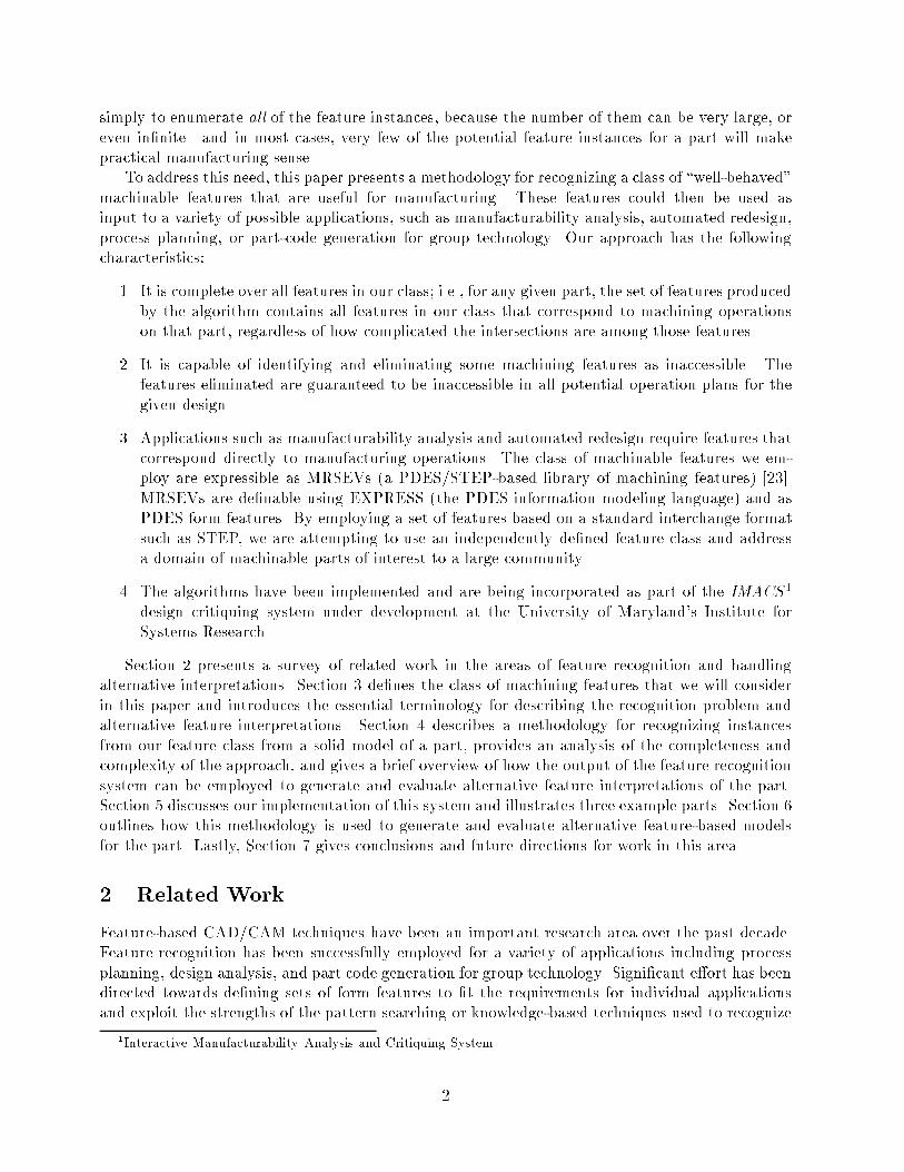
m11m12
Figure 16: Twelve milling features from Figure 15.
behaved features. By making modi�cations to the operations in the previously generated plans,it creates modi�ed versions of the design that, in addition to satisfying design requirements, haveimproved manufacturability [6]. The new designs are presented to the designer as alternativepossibilities to be considered.
The following examples illustrate some of the functionality of our approach:
Example 1 In the case of the part in Figure 1, the 32 o�set, accessible well-behaved features arepictured in Figure 13.
Example 2. One of the more di�cult feature instances to recognize is that of a pocket-milledfeature whose bottom surface has been removed through interaction with other features. Fig-ure 9(b), presents a part with interacting milling features. In this case, the bottom surface of thepocket-milled feature has been eliminated through interaction with other features.
For this feature, the orientation is determined from the edges e1 and e2. A pro�le for thefeature is found through the projection of the part faces along the normal of the plane passingthrough e1 and e2, as shown in Figure 14(a). One projection direction along the normal yields anon-empty edge pro�le E; the location for the bottom surface of the pocket-milling feature canthen be calculated (Figure 14(b)). The edge pro�le E can then be swept to produce an instance ofa primary pocket-milling feature m1, shown in Figure 14(c).
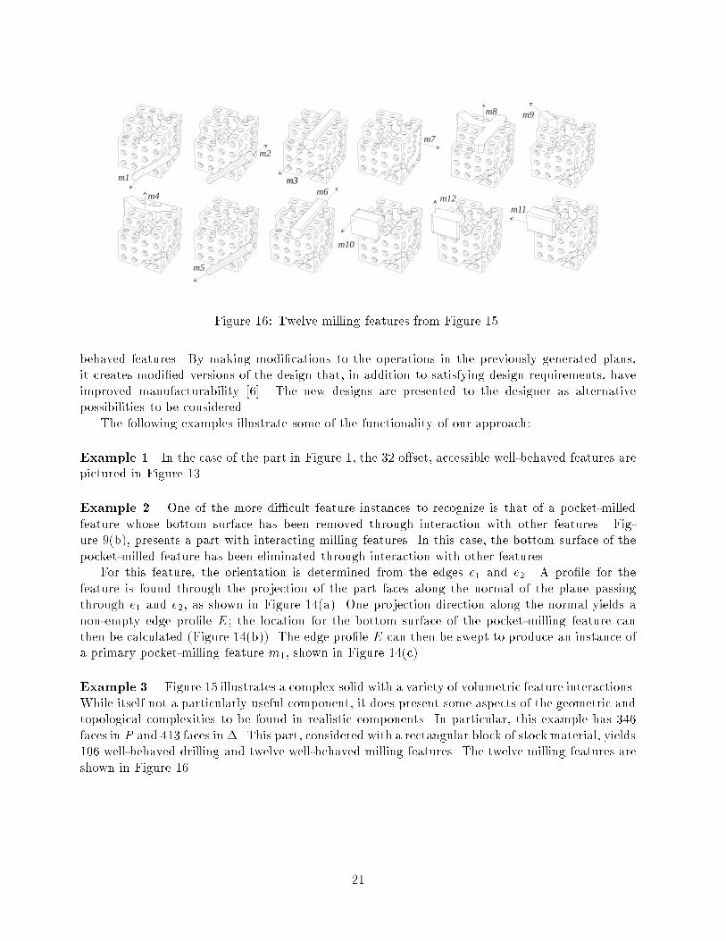
Example 3. Figure 15 illustrates a complex solid with a variety of volumetric feature interactions.While itself not a particularly useful component, it does present some aspects of the geometric andtopological complexities to be found in realistic components. In particular, this example has 346faces in P and 413 faces in �. This part, considered with a rectangular block of stockmaterial, yields106 well-behaved drilling and twelve well-behaved milling features. The twelve milling features areshown in Figure 16.
21

F1 =
8>>>>>>>>>>>>>>>>>>>>>>>>>><>>>>>>>>>>>>>>>>>>>>>>>>>>:
h1 h2 h3 h4
h5 h6 h7 m1 m2
m3 m4 m5 m6
9>>>>>>>>>>>>>>>>>>>>>>>>>>=>>>>>>>>>>>>>>>>>>>>>>>>>>;
F2 =
8>>>>>>>>>>>>>>>>>>>>>>>>>>><>>>>>>>>>>>>>>>>>>>>>>>>>>>:
h1 h2 h3 h8
h9 h10 h11 m1 m2
m7 m8 m9 m10
9>>>>>>>>>>>>>>>>>>>>>>>>>>>=>>>>>>>>>>>>>>>>>>>>>>>>>>>;
Figure 17: Two alternative feature-based models for the part in Figure 1(b).
22
6 Feature-Based Models
As mentioned in Section 5, the features produced by the Build Features algorithm given inSection 4 are used as input to a module that uses these features to generate and evaluate alternativeoperation plans for the machining of the part. A key step in generating alternative operation plans isto generate alternative feature-based models, which are sets of features that correspond to possibleways to machine the part.
A feature-based model (FBM) is a �nite set of feature instances F = ff1; f2; f3; : : : ; fng (in thiscase from the class of machining featuresM), that describe the volume of material to be removedby a set of machining features to create a part P from a piece of stock S. More speci�cally, anFBM is any �nite set of machining features with the following properties:
1. Su�ciency: the features in F describe one possible way to interpret �: S �� P �Sf2F f .
2. Necessity: no proper subset of F contains �: for all fi 2 F; S �� P 6�Sf2(F�ffig) f . In this
way, an FBM does not contain redundant features and each feature of F contributes to theinterpretation of the part.
3. Validity: in general, validity would require that f meet machinability requirements suchas those for accessibility, �xturability, and tolerances. However, development of a generalmethodology that simultaneously considers all of these issues is beyond the scope of thiswork. Thus, in this paper, we will consider a feature to be valid if it is not inaccessible asdiscussed in Section 3.4, and if the volume described by f does not intersect the part P ; i.e.,for all fi in F; fi \� P = ;.
There may be many FBMs of P and S, each corresponding to a di�erent interpretation of the partP as a subset of the set of well-behaved features F found by Build Features. A particular F
need not model the optimal way of creating the design as there may exist many alternatives, eachcorresponding to a di�erent collection of machining operations that could be used to produce thedesign from a given piece of stock material.
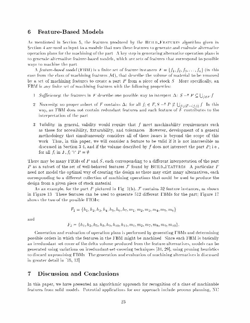
As an example, for the part P pictured in Fig. 1(b), F contains 32 feature instances, as shownin Figure 13. These features can be used to generate 512 di�erent FBMs for the part; Figure 17shows the two of the possible FBMs:
F1 = fh1; h2; h3; h4; h5; h6; h7; m1; m2; m3; m4; m5; m6g
andF2 = fh1; h2; h3; h8; h9; h10; h11; m1; m2; m7; m8; m9; m10g:
Generation and evaluation of operation plans is performed by generating FBMs and determiningpossible orders in which the features in the FBM might be machined. Since each FBM is basicallyan irredundant set cover of the delta volume produced from the feature alternatives, models can begenerated using variations on irredundant-set-covering techniques [34, 29], using pruning heuristicsto discard unpromising FBMs. The generation and evaluation of machining alternatives is discussedin greater detail in [15, 13].
7 Discussion and Conclusions
In this paper, we have presented an algorithmic approach for recognition of a class of machinablefeatures from solid models. Potential applications for our approach include process planning, NC
23

part programming, �xture design and selection, and manufacturability evaluation. We are incor-porating this approach into a system for automatically analyzing designs and providing feedbackto the designer about their manufacturability: the IMACS design analysis and critiquing systemunder development at the University of Maryland's Institute for Systems Research.
Some of the distinguishing characteristics of our approach include:
1. The feature recognition algorithm is complete over our class of features, regardless of whetherthe features intersect with each other in complex ways. Knowing the limits on complete-ness is useful for applications such as manufacturability analysis, in which determining themanufacturability of a design may require trying many alternative feature-based models tocalculate which provide the best operation plans.
2. Our approach incorporates characteristics to aid in downstream applications such as man-ufacturability evaluation and process planning: it handles features created by a variety ofmachining operations, including drilling, milling, chamfering, blending, and �lleting; whenpossible, the features recognized are o�set to account for the dimensions of the cutting toolto be used; and inaccessible features are discarded.
3. The algorithm's worst-case time complexity is polynomial in the number of edges in thedelta volume and requires only a quadratic number of solid modeling operations. This repre-sents an improvement over approaches that employ techniques that include exponential-timealgorithms, and those that attempt to produce all of the often exponential number of feature-based models during the recognition phase. It should be noted that some of these existingapproaches include the complex computations related to downstream applications as part ofthe recognition phase.
Some of the issues not yet addressed by this work include the following:
1. It would be valuable to investigate whether or not the completeness and complexity resultscan be extended to more complex feature types (such as composite features or feature groups)or to more diverse manufacturing domains and processes.
2. In recognizing features, our approach currently uses only geometric and topological informa-tion. It will be important to eventually incorporate the use of information such as tolerances,design features, functional requirements, and data relating to design history and intent.
Future goals include extending our results to include other, more complex, features; adapting theimplementation to operate incrementally (i.e., making the necessary changes to the set of featurealternatives as the designer interactively makes design modi�cations); and exploring how to reducethe time complexity through simpli�cation of the CAD model while still maintaining completeness.
Acknowledgements
This work was supported in part by NSF Grants NSFD CDR-88003012 and DDM-9201779.
References
[1] Tien-Chien Chang. Expert Process Planning for Manufacturing. Addison-Wesley PublishingCo., 1990.
24

[2] S. H. Chuang and M. R. Henderson. Three-dimensional shape pattern recognition using vertexclassi�cation and the vertex-edge graph. Computer Aided Design, 22(6):377{387, June 1990.
[3] S. H. Chuang and M. R. Henderson. Compound feature recognition by web grammar parsing.Research in Engineering Design, 2(3):147{158, 1991.
[4] J. Corney and D. E. R. Clark. Method for �nding holes and pockets that connect multiplefaces in 212d objects. Computer Aided Design, 23(10):658{668, December 1991.
[5] J. Corney and D. E. R. Clark. Face based feature recognition: Generalizing special cases.International Journal of Computer Integrated Manufacturing, 6(1 & 2):39{50, 1993.
[6] Diginta Das, Satyandra K. Gupta, and Dana S. Nau. Reducing setup cost by automatedgeneration of redesign suggestions. In Kosuke Ishii, editor, ASME Computers in EngineeringConference, pages 159{170. ASME, September 1994.
[7] Leila De Floriani. Feature extraction from boundary models of three-dimensional objects.IEEE Transactions on Pattern Analysis and Machine Intelligence, 11(8), August 1989.
[8] Xin Dong. Geometric Feature Extraction for Computer-Aided Process Planning. PhD thesis,Rensselaer Polytechnic Institute, Troy, NY, USA, 1988.
[9] R. Gadh and F. B. Prinz. Recognition of geometric forms using the di�erential depth �lter.Computer Aided Design, 24(11):583{598, November 1992.
[10] P. Gavankar and M. R. Henderson. Graph-based extraction of protrusions and depressionsfrom boundary representations. Computer Aided Design, 22(7):442{450, September 1990.
[11] S. K. Gupta, D. S. Nau, W. C. Regli, and G. Zhang. A methodology for systematic generationand evaluation of alternative operation plans. In Jami Shah, Martti M�antyl�a, and Dana Nau,editors, Advances in Feature Based Manufacturing. Elsevier/North Holland, 1993.
[12] Satyandra K. Gupta. Automated Manufacturability Analysis of Machined Parts. PhD thesis,The University of Maryland, College Park, MD, 1994.
[13] Satyandra K. Gupta, Thomas R. Kramer, Dana S. Nau, William C. Regli, and GuangmingZhang. Building MRSEV models for CAM applications. Advances in Engineering Software,1994. To appear.
[14] Satyandra K. Gupta, William C. Regli, and Dana S. Nau. Manufacturing feature instances:Which ones to recognize? Technical Report CS-TR-3376, UMIACS-TR-94-127, ISR-TR-94-81,The University of Maryland, College, Park, November 1994.
[15] S.K. Gupta and D.S. Nau. A systematic approach for analyzing the manufacturability ofmachined parts. Computer Aided Design, 1994. To appear.
[16] Mark R. Henderson. Extraction of Feature Information from Three-Dimensional CAD Data.PhD thesis, Purdue University, West Lafayette, IN, USA, 1984.
[17] Christoph M. Ho�man. Geometric and Solid Modeling: An Introduction. Morgan KaufmannPublishers Incorporated, CA, 1989.
25

[18] S. Joshi and T. C. Chang. Graph-based heuristics for recognition of machined features from a3D solid model. Computer-Aided Design, 20(2):58{66, March 1988.
[19] R. Karinthi and D. Nau. An algebraic approach to feature interactions. IEEE Trans. Pattern
Analysis and Machine Intelligence, 14(4):469{484, April 1992.
[20] Y. S. Kim. Recognition of form features using convex decomposition. Computer Aided Design,24(9):461{476, September 1992.
[21] Yong Se Kim and D. J. Wilde. A convergent convex decomposition of polyhedral objects.Transactions of the ASME, 114:468{476, September 1992.
[22] Thomas R. Kramer. A parser that converts a boundary representation into a features repre-sentation. International Journal of Computer Integrated Manufacturing, 2(3):154{163, 1989.
[23] Thomas R. Kramer. A library of material removal shape element volumes (MRSEVs). Techni-cal Report NISTIR 4809, The National Institute of Standards and Technology, Gaithersburg,MD 20899, March 1992.
[24] Lycourgos K. Kyprianou. Shape Classi�cation in Computer Aided Design. PhD thesis, ChristCollege, University of Cambridge, Cambridge, United Kingdom, 1980.
[25] Timo Laakko and Martti M�antyl�a. Feature modelling by incremental feature recognition.Computer Aided Design, 25(8):479{492, August 1993.
[26] Martti M�antyl�a. An Introduction to Solid Modeling. Computer Science Press, College Park,MD, 1988.
[27] M.Marefat and R. L. Kashyap. Geometric reasoning for recognition of three-dimensional objectfeatures. IEEE Transactions on Pattern Analysis and Machine Intelligence, 12(10):949{965,October 1990.
[28] Michael Marefat and R. L. Kashyap. Automatic construction of process plans from solidmodel representations. IEEE Transactions on Systems, Man, and Cybernetics, 22(5):1097{1115, September/October 1992.
[29] Yun Peng and James A. Reggia. Diagnostic problem-solving with causal chaining. InternationalJournal of Intelligent Systems, 2:265{302, 1987.
[30] Thomas J. Peters. Encoding mechanical design features for recognition via neural nets. Re-search in Engineering Design, 4(2):67{74, 1992.
[31] Thomas J. Peters. Mechanical design heuristics to reduce the combinatorial complexity forfeature recognition. Research In Engineering Design, 4:195{201, 1993.
[32] J. Miguel Pinilla, Susan Finger, and Friedrich B. Prinz. Shape feature description usingan augmented topology graph grammar. In Proceedings NSF Engineering Design ResearchConference, pages 285{300. National Science Foundation, June 1989.
[33] S. Prabhakar and M. R. Henderson. Automatic form-feature recognition using neural-network-based techniques on boundary representations of solid models. Computer Aided Design,24(7):381{393, July 1992.
26
[34] J. A. Reggia, D. S. Nau, and P. Y.Wang. A formal model of diagnostic inference. II. algorithmicsolution and applications. Information Sciences, 37:257{285, 1985.
[35] William C. Regli. Geometric Algorithms for Recognition of Features from Solid Models. PhDthesis, The University of Maryland, College Park, MD, 1995. In preparation.
[36] Aristides A. G. Requicha. Representation for rigid solids: Theory, methods, and systems.Computing Surveys, 12(4):437{464, December 1980.
[37] David W. Rosen, John R. Dixon, and Susan Finger. Conversions of feature-based representa-tions via graph grammar parsing. In AMSE Design Theory Methodology Conference, 1992.
[38] Scott A. Sa�er and Susan Finger. Parsing features in solid geometric models. In European
Conference on Arti�cial Intelligence, 1990.
[39] Hiroshi Sakurai and Chia-Wei Chin. De�nition and recognition of volume features for processplanning. In Jami Shah, Martti M�antyl�a, and Dana Nau, editors, Advances in Feature BasedManufacturing, chapter 4, pages 65{80. Elsevier/North Holland, 1994.
[40] Hiroshi Sakurai and David C. Gossard. Recognizing shape features in solid models. IEEE
Computer Graphics & Applications, September 1990.
[41] Jami Shah, Martti M�antyl�a, and Dana Nau, editors. Advances in Feature Based Manufacturing.Elsevier/North Holland, 1994.
[42] J. H. Vandenbrande and A. A. G. Requicha. Spatial reasoning for the automatic recognitionof machinable features in solid models. IEEE Transactions on Pattern Analysis and Machine
Intelligence, 15(12):1269, December 1993.
[43] Douglas L. Waco and Yong Se Kim. Geometric reasoning for machining features using convexdecomposition. Computer Aided Design, 26(6):477{489, June 1994.
[44] Tony C. Woo. Feature extraction by volume decomposition. In Conference on CAD/CAMTechnology in Mechanical Engineering, pages 76{94, March 1982.
27