Embed Size (px)
Citation preview
American Institute of Aeronautics and Astronautics
1
Extravehicular Activity Technology Development Status and Forecast
Cinda Chullen1 and David T. Westheimer2 NASA Johnson Space Center, Houston, TX, 77058
The goal of NASA’s current EVA technology effort is to further develop technologies that will be used to demonstrate a robust EVA system that has application for a variety of future missions including microgravity and surface EVA. Overall the objectives will be to reduce system mass, reduce consumables and maintenance, increase EVA hardware robustness and life, increase crew member efficiency and autonomy, and enable rapid vehicle egress and ingress. Over the past several years, NASA realized a tremendous increase in EVA system development as part of the Exploration Technology Development Program and the Constellation Program. The evident demand for efficient and reliable EVA technologies, particularly regenerable technologies was apparent under these former programs and will continue to be needed as future mission opportunities arise. The technological need for EVA in space has been realized over the last several decades by the Gemini, Apollo, Skylab, Space Shuttle, and the International Space Station (ISS) programs. EVAs were critical to the success of these programs. Now with the ISS extension to 2028 in conjunction with a current forecasted need of at least eight EVAs per year, the EVA hardware life and limited availability of the Extravehicular Mobility Units (EMUs) will eventually become a critical issue. The current EMU has successfully served EVA demands by performing critical operations to assemble the ISS and provide repairs of satellites such as the Hubble Space Telescope. However, as the life of ISS and the vision for future mission opportunities are realized, a new EVA systems capability will be needed and the current architectures and technoliges under development offer significant improvements over the current flight systems. In addition to ISS, potential mission applications include EVAs for missions to Near Earth Objects (NEO), Phobos, or future surface missions. Surface missions could include either exploration of the Moon or Mars. Providing an EVA capability for these types of missions enables in-space construction of complex vehicles or satellites, hands on exploration of new parts of our solar system, and engages the public through the inspiration of knowing that humans are exploring places that they have never been before. This paper offers insight into what is currently being developed and what the potential opportunities are in the forecast.
Nomenclature ACES = Advanced Crew Escape System AES = Advanced Exploration Systems BPV = Back Pressure Valve CM = Crew Member CO2 = Carbon Dioxide COTS = Commercial Off-The-Shelf D-RATS = Desert Research and Technology Studies EMU = Extravehicular Mobility Unit ETDD = Enabling Technology Development and Demonstration ETDP = Exploration Technology Development Program EVA = Extravehicular Activity FMEA = Failure Modes and Effect Analyses HoFi = Hollow Fiber H2O = Water HAT = Human Architecture Team ISS = International Space Station IVA = Intervehicular Activity 1 Deputy Project Manager, EVA Technology Development, 2101 NASA Parkway, Houston, Texas, 77058/EC5. 2 Project Manager, EVA Technology Development, 2101 NASA Parkway, Houston, Texas, 77058/EC5.
https://ntrs.nasa.gov/search.jsp?R=20110012989 2020-07-14T15:09:02+00:00Z
American Institute of Aeronautics and Astronautics
2
JSC = Johnson Space Center Kbps = kilobit per second LCG = Liquid Cooling Garment LCVG = Liquid Cooling and Ventilation Garment LEA = Launch, Entry, and Abort LED = Light Emitting Diode LEO = Low Earth Orbit NASA = National Aeronautics and Space Administration NEO = Near Earth Object O2 = Oxygen OCT = Office of Chief Technologist OLED = Organic Light Emitting Diode PAS = Power, Avionics, and Software PLSS = Portable Life Support System psia = Pounds per Square Inch (absolute) psid = Pounds per Square Inch (differential) SBIR = Small Business Innovative Research (SBIR) SE&I = System Engineering & Integration SWME = Spacesuit Water Membrane Evaporator SWaP = Size, Weight, and Power TCC = Trace Contaminant Control TMG = Thermal Micrometeoroid Garment TMDG = Thermal Micrometeoroid and Dust Garment TRL = Technology Readiness Level
I. Introduction pacesuits are unique and special in many ways. Primarily, they provide astronauts a means to survive in the harse environment of vacuum. There are essentially two functional approaches to spacesuit configurations. The
first type is for the purpose of performing Intravehicular Activity (IVAs) and the second type is for the purpose of performing Extravehicular Activity (EVAs). IVA spacesuits primarily support launch, entry, and abort (LEA) activities while an astronaut is launching into space or returning to Earth. LEA suits are mainly dependent on the spacecraft to provide primary life support functions. However, the LEA suits are normally configured with an emergency life support mechanism that is separate from the spacecraft for crew survival. The latest developed suit to support LEA activities is the Advanced Crew Escape System (ACES) for use on the Space Shuttle. The ACES protects the astronaut from on-pad emergencies, vehicle cabin depressurization, toxic chemicals, and abort emergencies. The ACES was developed in the mid-1990s to address crew survival issues after the Challenger accident. Performing the function of EVA continues to be one of the most critical components of human space flight due to the hazardous space environment. By providing a pressurized oxygen rich enviroment, the EVA spacesuit is a life sustaining environment while an astronaut performs useful tasks. This safe haven protects a single-crewmember (CM) by providing life support in a challenging EVA environment external to the primary space vehicle. Pressurized spacesuits have been used in every human space program thus far. The evolution of a pressurized spacesuit originates as far back as 1933 when Wiley Post, an American aviator, iniated the development of a fully pressurized suit in a effort to help him break the existing world aircraft altitude record.1 Since then there have been a number of technological achievements and advancements in the EVA spacesuit arena. Several different EVA spacesuits have been built to meet the unique functional requirements. The latest that was built and is still in operation is the Shuttle Extravehicular Mobility Unit (EMU). The Shuttle EMU was developed in the 1970s along with the Space Shuttle itself. It was the last developed pressurized flight suit that included a life support system and a spacesuit assembly together to enable space walks in zero gravity.2 Because the EVA spacesuit supports a single CM as a stand-alone system, the EVA spacesuit is often referred to as a “mini spacecraft” or a “one-person spacecraft”.3 EVA spacesuits have allowed CMs to walk on the surface of the Moon, save Skylab, inspect critical components outside the Space Shuttle, build the International Space Station (ISS), capture satellites, repair the Hubble Space Telescope, and perform many other critical jobs during the history of human space flight. Just as in the past, a future EVA spacesuit, whether designed for orbital operations or
S

American Institute of Aeronautics and Astronautics
3
planetary surface explorations systems, must continue to be safe and reliable, and must provide a high degree of performance capabilities.4
This paper provides a perspective on the direction of EVA technology development over the last five years. The content presented originatated with the Constellation Program (CxP) vision of returning to the Moon and has transitioned to a microgravity application over the past few years.
II. Background
Fig. 2 shows the EVA Technology Development Roadmap. This Roadmap is in line with the President’s policy guidelines. This figure reveils other potential destinations on a “flexible path” including Near Earth Objects (NEOs) and eventually surface missions to the Moon, Phobos, or Mars. Continued EVA technology development is needed to enable human exploration based on a “flexible path” philosophy. These missions will present environmental challenges, such as thermal extremes, abrasive regolith, and radiation hazards for the CM. Communication may be a significant challenge due increasing time delays and increased network complexity. The requirement to perform EVAs on the surface of low gravity objects could present additional challenges for crew mobility. Missions to planetary surfaces will require technology advancement durations in areas such as increased component life, protection from radiation events, mobility in a partial gravity environment, dust mitigation, interfaces with rovers and habitations, high data rate network based communication, innovative life support systems that minimize consumables or take advantage of in-situ resources, smart caution and warning capabilities, and advanced information systems that enable crew autonomy.
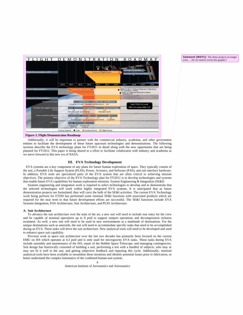
As NASA’s new initiatives are implemented, the EVA Technology Roadmap can be a planning tool to communicate the forecast of what the future holds. For example, the ISS could be used for zero-g evaluation of various pressure garment and life-support designs. As shown in Fig. 3, current EVA system development plans include a series of subsystem and system evaluations that will start with component level demonstrations and breadboard laboratory testing and progress to a full demonstration of an EVA system in 2016.
Figure 2. EVA Technology Development Roadmap
American Institute of Aeronautics and Astronautics
4
Additionally, it will be important to partner with the commercial industry, academia, and other government entities to facilitate the development of these future spacesuit technologies and demonstrations. The following sections describe the EVA technology plans for FY2011 in detail along with the new opportunies that are being planned for FY2012. This paper is being shared in a effort to facilitate colaboraton with industry and academia as we move forward in this new era of NASA.
III. EVA Technology Development EVA systems are a key component of any plans for future human exploration of space. They typically consist of
the suit, a Portable Life Support System (PLSS), Power, Avionics, and Software (PAS), and suit interface hardware. In addition, EVA tools are specialized parts of the EVA system that are often critical to achieving mission objectives. The primary objective of the EVA Technology plan for FY2011 is to develop technologies and systems that enable future EVA capabilities for human exploration missions. System Engineering & Integration (SE&I) Systems engineering and integration work is required to select technologies to develop and to demonstrate that the selected technologies will work within highly integrated EVA systems. It is anticipated that as future demonstration projects are formulated, they will carry the bulk of the SE&I activities. The current EVA Technology work being perform for ETDD has performed some minimal SE&I functions with associated products which are required for the near term to that future development efforts are successful. The SE&I functions include EVA Systems Integration, PAS Architecture, Suit Architecture, and PLSS Architecture. A. Suit Architecture To advance the suit architecture over the state of the art, a new suit will need to include rear entry for the crew and be capable of nominal operations up to 8 psid to support suitport operations and decompression sickness treatment. As well, a new suit will need to be used in new environments at a multitude of destinations. For the unique destinations such as asteroids, the suit will need to accommodate specific tasks that need to be accomplished during an EVA. These tasks will drive the suit architecture. New analytical tools will need to be developed and used to enhance space suit capability. Previous work in space suit architecture over the last two decades has primarily been focused on the current EMU on ISS which operates at 4.3 psid and is only used for microgravity EVA tasks. These tasks during EVA include assembly and maintenance of the ISS, repair of the Hubble Space Telescope, and managing contingencies. Suit design has historically consisted of building a suit, performing a test with a handful of subjects, who may or may not fit it well in the suit, and getting subjective feedback and repeating this cycle. Additionally, minimal analytical tools have been available to streamline these iterations and identify potential issues prior to fabrication, or better understand the complex kinematics of the combined human-suit system.
Figure 3. Flight Demonstraion Roadmap
Comment [WDT1]: The demo projects no longer exist…. Do we need to revise this graphic?
American Institute of Aeronautics and Astronautics
5
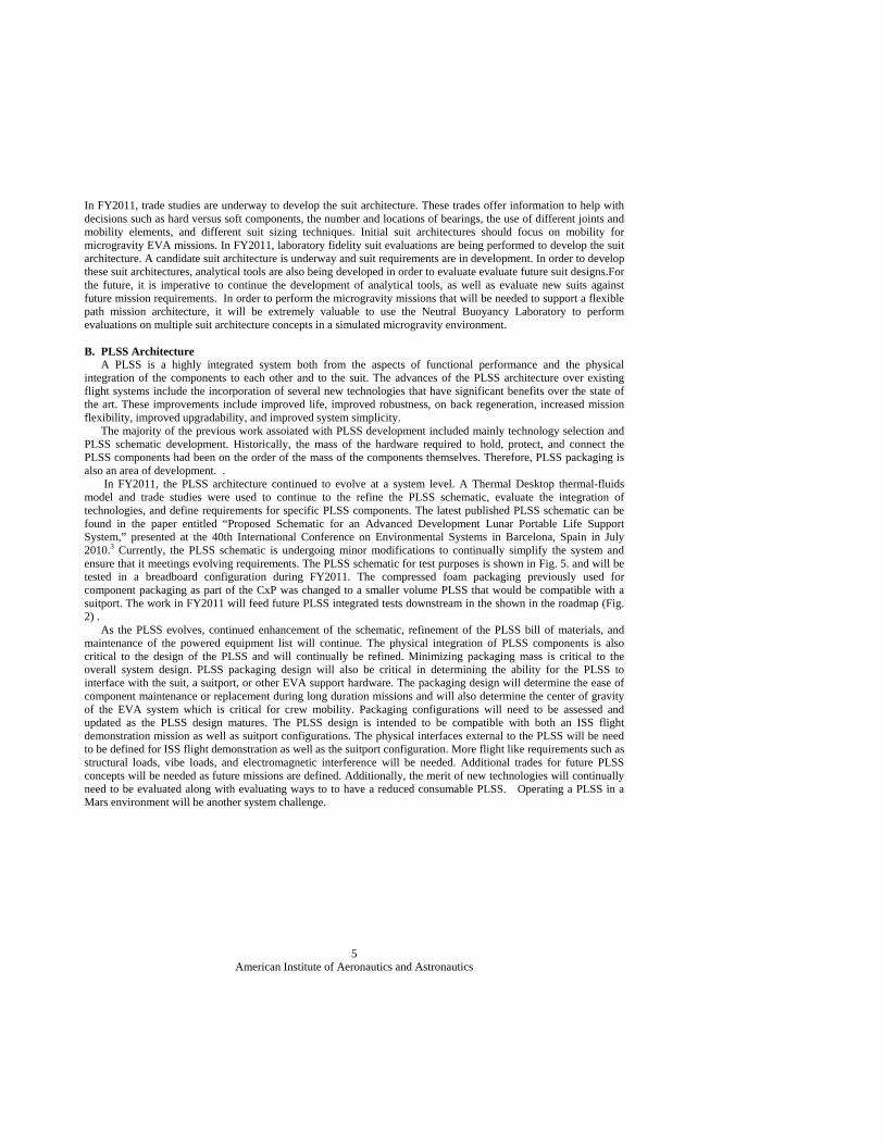
In FY2011, trade studies are underway to develop the suit architecture. These trades offer information to help with decisions such as hard versus soft components, the number and locations of bearings, the use of different joints and mobility elements, and different suit sizing techniques. Initial suit architectures should focus on mobility for microgravity EVA missions. In FY2011, laboratory fidelity suit evaluations are being performed to develop the suit architecture. A candidate suit architecture is underway and suit requirements are in development. In order to develop these suit architectures, analytical tools are also being developed in order to evaluate evaluate future suit designs.For the future, it is imperative to continue the development of analytical tools, as well as evaluate new suits against future mission requirements. In order to perform the microgravity missions that will be needed to support a flexible path mission architecture, it will be extremely valuable to use the Neutral Buoyancy Laboratory to perform evaluations on multiple suit architecture concepts in a simulated microgravity environment. B. PLSS Architecture A PLSS is a highly integrated system both from the aspects of functional performance and the physical integration of the components to each other and to the suit. The advances of the PLSS architecture over existing flight systems include the incorporation of several new technologies that have significant benefits over the state of the art. These improvements include improved life, improved robustness, on back regeneration, increased mission flexibility, improved upgradability, and improved system simplicity. The majority of the previous work assoiated with PLSS development included mainly technology selection and PLSS schematic development. Historically, the mass of the hardware required to hold, protect, and connect the PLSS components had been on the order of the mass of the components themselves. Therefore, PLSS packaging is also an area of development. . In FY2011, the PLSS architecture continued to evolve at a system level. A Thermal Desktop thermal-fluids model and trade studies were used to continue to the refine the PLSS schematic, evaluate the integration of technologies, and define requirements for specific PLSS components. The latest published PLSS schematic can be found in the paper entitled “Proposed Schematic for an Advanced Development Lunar Portable Life Support System,” presented at the 40th International Conference on Environmental Systems in Barcelona, Spain in July 2010.3 Currently, the PLSS schematic is undergoing minor modifications to continually simplify the system and ensure that it meetings evolving requirements. The PLSS schematic for test purposes is shown in Fig. 5. and will be tested in a breadboard configuration during FY2011. The compressed foam packaging previously used for component packaging as part of the CxP was changed to a smaller volume PLSS that would be compatible with a suitport. The work in FY2011 will feed future PLSS integrated tests downstream in the shown in the roadmap (Fig. 2) . As the PLSS evolves, continued enhancement of the schematic, refinement of the PLSS bill of materials, and maintenance of the powered equipment list will continue. The physical integration of PLSS components is also critical to the design of the PLSS and will continually be refined. Minimizing packaging mass is critical to the overall system design. PLSS packaging design will also be critical in determining the ability for the PLSS to interface with the suit, a suitport, or other EVA support hardware. The packaging design will determine the ease of component maintenance or replacement during long duration missions and will also determine the center of gravity of the EVA system which is critical for crew mobility. Packaging configurations will need to be assessed and updated as the PLSS design matures. The PLSS design is intended to be compatible with both an ISS flight demonstration mission as well as suitport configurations. The physical interfaces external to the PLSS will be need to be defined for ISS flight demonstration as well as the suitport configuration. More flight like requirements such as structural loads, vibe loads, and electromagnetic interference will be needed. Additional trades for future PLSS concepts will be needed as future missions are defined. Additionally, the merit of new technologies will continually need to be evaluated along with evaluating ways to to have a reduced consumable PLSS. Operating a PLSS in a Mars environment will be another system challenge.
American Institute of Aeronautics and Astronautics
6
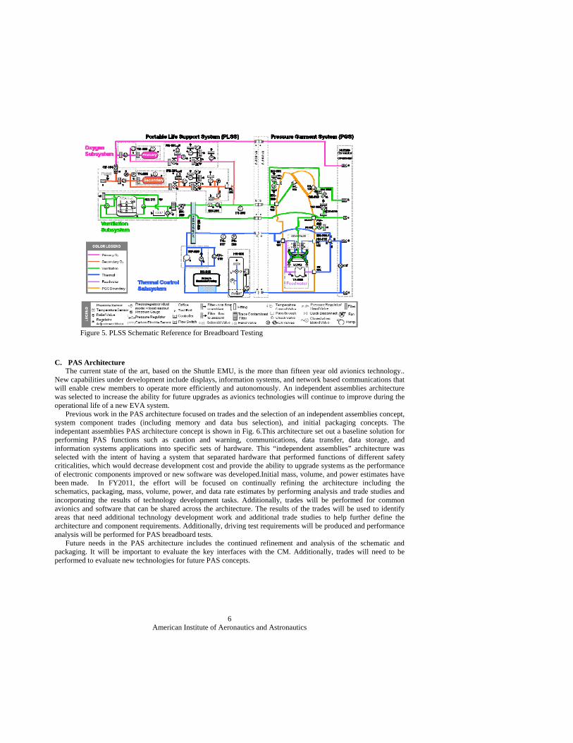
C. PAS Architecture The current state of the art, based on the Shuttle EMU, is the more than fifteen year old avionics technology.. New capabilities under development include displays, information systems, and network based communications that will enable crew members to operate more efficiently and autonomously. An independent assemblies architecture was selected to increase the ability for future upgrades as avionics technologies will continue to improve during the operational life of a new EVA system. Previous work in the PAS architecture focused on trades and the selection of an independent assemblies concept, system component trades (including memory and data bus selection), and initial packaging concepts. The indepentant assemblies PAS architecture concept is shown in Fig. 6.This architecture set out a baseline solution for performing PAS functions such as caution and warning, communications, data transfer, data storage, and information systems applications into specific sets of hardware. This “independent assemblies” architecture was selected with the intent of having a system that separated hardware that performed functions of different safety criticalities, which would decrease development cost and provide the ability to upgrade systems as the performance of electronic components improved or new software was developed.Initial mass, volume, and power estimates have been made. In FY2011, the effort will be focused on continually refining the architecture including the schematics, packaging, mass, volume, power, and data rate estimates by performing analysis and trade studies and incorporating the results of technology development tasks. Additionally, trades will be performed for common avionics and software that can be shared across the architecture. The results of the trades will be used to identify areas that need additional technology development work and additional trade studies to help further define the architecture and component requirements. Additionally, driving test requirements will be produced and performance analysis will be performed for PAS breadboard tests. Future needs in the PAS architecture includes the continued refinement and analysis of the schematic and packaging. It will be important to evaluate the key interfaces with the CM. Additionally, trades will need to be performed to evaluate new technologies for future PAS concepts.
Figure 5. PLSS Schematic Reference for Breadboard Testing
American Institute of Aeronautics and Astronautics
7
IV. Suit Hardare
The suit is the component that the CM physically wears, and the suit assembly contains components that physically interface with the CM. The term “suit” is synonymous with the SSA and the PGS used in other flight and development programs.
The primary functions of the suit are to provide a habitable environment in hazardous conditions and provide mobility for CMs to perform work in all mission phases. The suit is made up of components such as the gloves, joint bearings, helmet, and boots as well as the multiple layers of hard- and softgoods. The suit also uses a complex system of mobility elements in the shoulders, arms, hips, legs, torso, boots, and gloves to optimize performance while pressurized without inhibiting unpressurized operations.
A. Gaps and Challenges Technology development needs are still substantial for many components of the suit. Key technology advances for future suits are required for the suit materials, gloves, helmet, lightweight bearings, mobility, Thermal Micrometeoroid and Dust Garment (TMDG), and modeling or analytical capabilities. Advances in these areas would provide improvement in suit component life, mobility, suit mass, comfort, and providing increased protection for future missions in more demanding environments. 1) Suit Materials Many suits components are composed of multiple layers of softgoods. These layers hold the pressurized oxygen within the suit and provide structural support, thermal insulation, and micrometeoroid and orbital debris (MMOD) protection. There are several technology advances that would benefit both of these applications. The100-percent oxygen environment inside of the suit limits the selection of materials and requires strict control of ignition sources. Additionally, spacesuit design overall would benefit from general materials research in both suit softgoods and lightweight materials for hard components. Previous work focused on biocontamination control. Microbial or fungal contamination of spacesuits can lead to a host of issues ranging from unpleasant odors to infections. The technical challenge is to prevent biological growth and to provide the CM with the safest possible suit for the environments experienced during planned ISS missions, long-duration missions, or storage periods while maintaining technical feasibility. A trade study was performed to review current materials and on-orbit cleaning methods employed for current suit bladders, liquid cooling garments (LCGs), and thermal comfort undergarments (TCUs). The objective of the study was to determine the material’s ability to repress or promote bio-contamination (bacterial and fungal) growth. The study also evaluated the
Figure 6. Indepentant Assemblies PAS Architecture Concept
American Institute of Aeronautics and Astronautics
8
advantages and disadvantages of various commercial off-the-shelf (COTS) antimicrobial textiles, textile treatments, and available cleaning agents through testing. Technical advancement needed in suit materials include ones that are antimicrobial, lightweight, selectively permeable, and fire resistant; that allow for simplified manufacturing; that provide improved environmental protection, radiation protection, abrasion, self sealing/healing, and improved MMOD protection; tolerant to thermal extremes (especially for a Mars mission), dust, charge dissipation, or that are self-diagnostic. These improvements would increase mission safety and the life of softgoods used in space applications. Increased radiation protection could increase the amount of time that humans can safely spend in space or an inflatable habitat and could increase the number of hours a CM could spend performing EVAs over his or her career. Materials that are self healing could improve MMOD protection by detecting punctures and even repairing damage. MMOD risk is currently estimated as a statistically evaluated risk that is a function of time. Much like improved radiation protection, decreased risk of suit or vehicle damage due to MMOD would enable longer mission durations or increased time performing EVAs. Additionally, technological advancements could help with mass saving on components like hard upper torsos and bearings. Even helmet materials could be improved so as to prevent scratching and provide resistant from fogging. 2) Helmet The helmet poses technical challenges that include the modularity of the helmet. Innovative designs are needed to minimize ventilation flow required for CO2 washout and to address helmet-display integration. Material developments are needed for helmets that focus on lightweight materials resistant to fogging or getting scratched during use. 3) Lightweight Bearings Bearings are critical elements of highly mobile pressure suits, but the price of increased mobility is a significant increase in mass. Therefore, low-mass bearings that can enable mobility performance would be highly beneficial to future spacesuits. In addition, nonmetallic bearings are lightweight and decrease the risk of shock caused by plasma charging of the suit during EVA. These bearings must carry structural loads, and they must be usable in a low-pressure oxygen system that includes a CM. Recent efforts have focused on using composites, however all advanced materials need to be considered for future efforts. Tasks that are needed include evaluating previously developed composite bearings and failures, revising manufacturing processes, and building and testing bearings. 4) Mobility Soft mobility elements, such as convoluted joints, can offer advantages over bearings in some applications. Soft mobility elements are particularly useful in suits that must protect crewmembers during the launch, abort, and entry mission phases because they enable more intimate contact between the CM, the harness, and the seat during these high-accelerations, minimizing the risk of injury. Soft mobility elements that maximize range of motion for shoulder, elbow, and knee joints are needed. NASA recently evaluated the joint torque data for a launch, entry, and abort (LEA) I-Suit and started evaluating multiple shoulder concepts. Soft hip investigations are also underway to assess mobility for the LEA application. 5) Thermal Micrometeoroid and Dust Garment (TMDG) Development areas include active dust mitigation technologies, increased durability in harsh space or planetary environments, lightweight materials, and variable heat transfer insulation. In addition, methods of analyzing the effects of MMOD impacts through a TMDG are desired. TMDG technologies should minimize the mass and volume required to provide the insulation for the suit. 6) Models
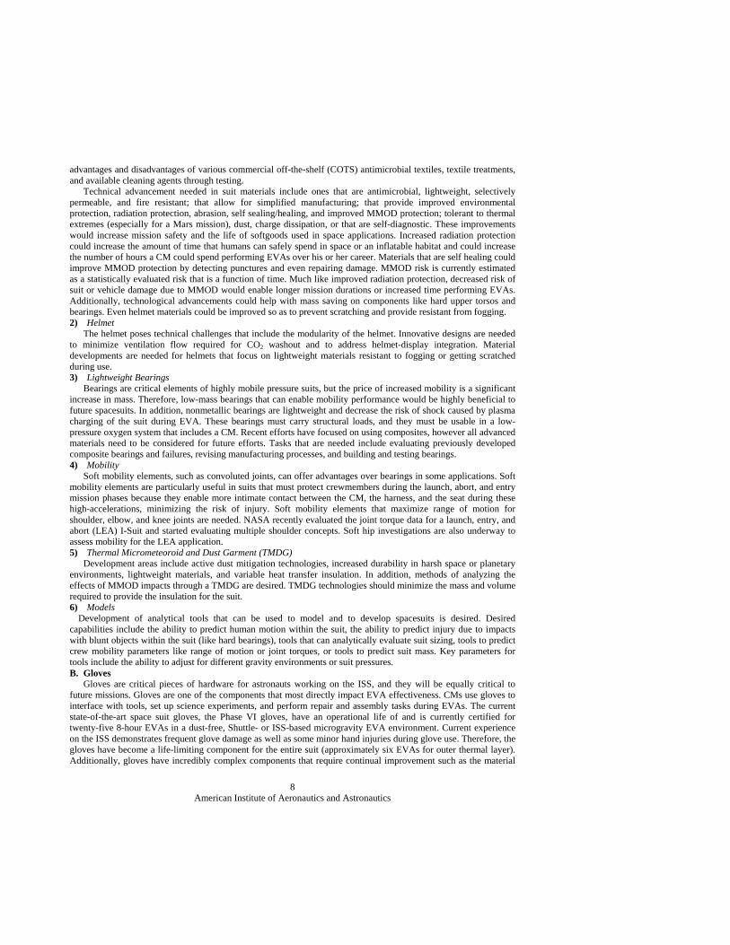
Development of analytical tools that can be used to model and to develop spacesuits is desired. Desired capabilities include the ability to predict human motion within the suit, the ability to predict injury due to impacts with blunt objects within the suit (like hard bearings), tools that can analytically evaluate suit sizing, tools to predict crew mobility parameters like range of motion or joint torques, or tools to predict suit mass. Key parameters for tools include the ability to adjust for different gravity environments or suit pressures. B. Gloves Gloves are critical pieces of hardware for astronauts working on the ISS, and they will be equally critical to future missions. Gloves are one of the components that most directly impact EVA effectiveness. CMs use gloves to interface with tools, set up science experiments, and perform repair and assembly tasks during EVAs. The current state-of-the-art space suit gloves, the Phase VI gloves, have an operational life of and is currently certified for twenty-five 8-hour EVAs in a dust-free, Shuttle- or ISS-based microgravity EVA environment. Current experience on the ISS demonstrates frequent glove damage as well as some minor hand injuries during glove use. Therefore, the gloves have become a life-limiting component for the entire suit (approximately six EVAs for outer thermal layer). Additionally, gloves have incredibly complex components that require continual improvement such as the material
American Institute of Aeronautics and Astronautics
9
and fabrication techniques used in eliminating seams in the palm to improve mobility, maintaining cut and abrasion resistance, and providing thermal protection. Previous testing characterized the durability of Phase VI gloves, which are currently used during ISS EVAs. The test simulated over 90 EVAs to identify areas of the glove design that need improvement. These tests were performed with gloves that were contaminated with lunar regolith stimulant. The results of the testing will be fed into the development of improved spacesuit gloves. The results indicated that although there was evident wear, the gloves did not receive the damage expected. In particular, the gloves showed some Thermal Micrometeoroid Garment (TMG) damage directly over the palm bar warrenting more improvement in this area. Glove test photos shown in Fig. 7.7 In FY2011, a glove development contract was awarded to Flagsuit with a scope of exploring new glove construction concepts. The Suit Hardware team is currently evaluating multiple innovative glove design features, will down select and produce a pair of gloves for further evaluation. Future missions will require many more EVAs than ISS missions, and the EVAs will be performed in a much harsher environment, greatly expanding the need to extend the life of gloves and the number of hours that a CM spends using gloves. The goal is to develop gloves that can provide acceptable mobility during operations that require pressures of up to 8.0 psid with a goal of 50 or more EVAs. Other glove development needs include improvements in glove materials, sizing methods, and manufacturing techniques and the development of finger and wrist joints that provide increased hand mobility or extend glove life. The overall goal is to continually explore new design concepts to improve glove mobility and comfort while maximizing life. C. Upper Torso Several changes must be made from the upper torso design used in the current EMU to support future exploration tasks. In order to be compatible with a suitport, the suit must have a rear entry hatch as opposed to being a waist entry suit. A rear entry hatch enables rapid donning and doffing and reduces shoulder injury risk. The suit must also be made for operations at higher pressures (8.3 psid as opposed to 4.3 psid) and for improvements in sizing and mobility. Also, a reduction in mass is needed. Improved sizing capabilities would be beneficial to increase the range of crew members who can fit a piece of hardware. This reduces life cycle cost through reducing the number of sizes, logistics, and the need to get hardware “up and down” during missions. It also simplifies meeting anthropometric range requirements. The previous work in this area focused on the initial evaluations of the suitport interface plate (SPIP) and integration of the suit in a suitport configuation.Effort is underway to evaluate new materials and joint designs. This assessment will be used to address suit architecture trades to provide improved mobility as compared to the Shuttle EMU. Deveopment needs in this area include the following: Incorporate lower level component and materials developments into future upper
torsos; Select a design and fabricate a rear entry upper torso; Characterize mobility through lab and NBL evaluations for a microgravity mission;
and Iterate on the design and increase the fidelity to address interfaces, materials selection
(reduced pressure, offgassing, and 100% oxygen environment).
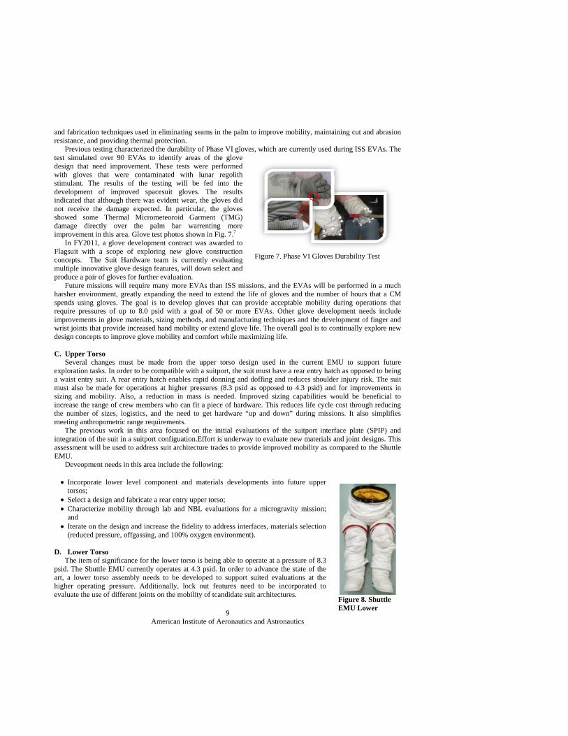
D. Lower Torso The item of significance for the lower torso is being able to operate at a pressure of 8.3 psid. The Shuttle EMU currently operates at 4.3 psid. In order to advance the state of the art, a lower torso assembly needs to be developed to support suited evaluations at the higher operating pressure. Additionally, lock out features need to be incorporated to evaluate the use of different joints on the mobility of tcandidate suit architectures.
Figure 7. Phase VI Gloves Durability Test
Figure 8. Shuttle EMU Lower
American Institute of Aeronautics and Astronautics
10
As far as previous work, no significant lower torso development work has been performed in the past decade. In FY2011, the plan includes the procurement for the design, buildup, and delivery of a Lower Torso test article that can be used in future suited evaluations. Additionally, pressurized suitport evaluations and suit architecture evaluations are being planned. For future development needs, a lower torso assembly that operates at 8.3 psid must be developed to support suited evaluations at these higher operating pressures. Additionally, lower torso requirements will need to be identified based on future NASA missions. The lower toroso will need to incorporate advances in materials, sizing methods, or improved fabrication techniques to improve mobility, increase life, or decrease mass. Laboratory evaluations will continue to be crucial along with Neutral Buoyancy Laboratory evaluations so as to characterize the mobility of the lower torso for not only microgravity missions but a multitude of other mission scenarios as well. The fidelity of the design will need to address interfaces, materials selection (reduced pressure, off gassing, and 100% oxygen environment). Therefore, it is important to iterate on the design in order to increase the fidelity.
V. Portable Life Support System (PLSS) Hardware The PLSS performs the functions that are required to keep a crewmember alive during an EVA. These include
maintaining thermal control of the astronaut, providing a pressurized oxygen environment, and removing CO2. PLSS subsystems include the thermal, ventilation, and oxygen subsystems.
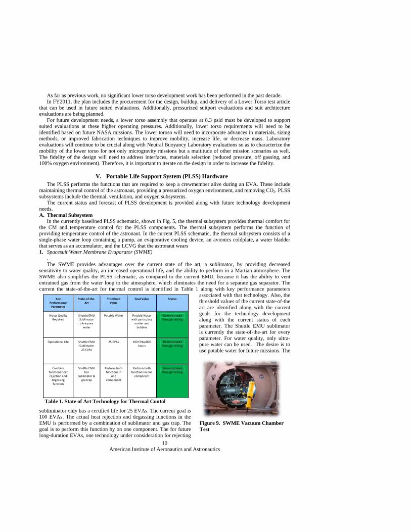
The current status and forecast of PLSS development is provided along with future technology development needs. A. Thermal Subsystem In the currently baselined PLSS schematic, shown in Fig. 5, the thermal subsystem provides thermal comfort for the CM and temperature control for the PLSS components. The thermal subsystem performs the function of providing temperature control of the astronaut. In the current PLSS schematic, the thermal subsystem consists of a single-phase water loop containing a pump, an evaporative cooling device, an avionics coldplate, a water bladder that serves as an accumulator, and the LCVG that the astronaut wears 1. Spacesuit Water Membrane Evaporator (SWME) . The SWME provides advantages over the current state of the art, a sublimator, by providing decreased sensitivity to water quality, an increased operational life, and the ability to perform in a Martian atmosphere. The SWME also simplifies the PLSS schematic, as compared to the current EMU, because it has the ability to vent entrained gas from the water loop to the atmosphere, which eliminates the need for a separate gas separator. The current the state-of-the-art for thermal control is identified in Table 1 along with key performance parameters
associated with that technology. Also, the threshold values of the current state-of-the art are identified along with the current goals for the technology development along with the current status of each parameter. The Shuttle EMU sublimator is currently the state-of-the-art for every parameter. For water quality, only ultra-pure water can be used. The desire is to use potable water for future missions. The
subliminator only has a certified life for 25 EVAs. The current goal is 100 EVAs. The actual heat rejection and degassing functions in the EMU is performed by a combination of sublimator and gas trap. The goal is to perform this function by on one component. The for future long-duration EVAs, one technology under consideration for rejecting
Figure 9. SWME Vacuum Chamber Test
Key Performance Parameter
State‐of‐the‐Art
Threshold Value
Goal Value Status
Water Quality Required
Shuttle EMU Sublimator ultra‐pure water
Potable Water Potable Water with particulate matter and bubbles
Demonstrated through testing
Operational Life Shuttle EMU Sublimator 25 EVAs
25 EVAs 100 EVAs/800 hours
Demonstrated through testing
Combine functions heat rejection and degassing function
Shuttle EMU has
sublimator & gas trap
Perform both functions in
one component
Perform both functions in one component
Demonstrated through testing
Table 1. State of Art Technology for Thermal Contol
American Institute of Aeronautics and Astronautics
11
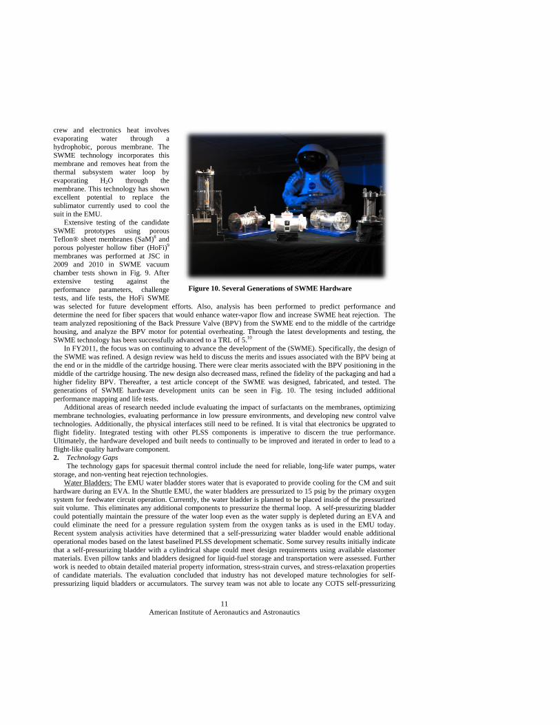
crew and electronics heat involves evaporating water through a hydrophobic, porous membrane. The SWME technology incorporates this membrane and removes heat from the thermal subsystem water loop by evaporating H2O through the membrane. This technology has shown excellent potential to replace the sublimator currently used to cool the suit in the EMU. Extensive testing of the candidate SWME prototypes using porous Teflon® sheet membranes (SaM)8 and porous polyester hollow fiber (HoFi)9 membranes was performed at JSC in 2009 and 2010 in SWME vacuum chamber tests shown in Fig. 9. After extensive testing against the performance parameters, challenge tests, and life tests, the HoFi SWME was selected for future development efforts. Also, analysis has been performed to predict performance and determine the need for fiber spacers that would enhance water-vapor flow and increase SWME heat rejection. The team analyzed repositioning of the Back Pressure Valve (BPV) from the SWME end to the middle of the cartridge housing, and analyze the BPV motor for potential overheating. Through the latest developments and testing, the SWME technology has been successfully advanced to a TRL of 5.10 In FY2011, the focus was on continuing to advance the development of the (SWME). Specifically, the design of the SWME was refined. A design review was held to discuss the merits and issues associated with the BPV being at the end or in the middle of the cartridge housing. There were clear merits associated with the BPV positioning in the middle of the cartridge housing. The new design also decreased mass, refined the fidelity of the packaging and had a higher fidelity BPV. Thereafter, a test article concept of the SWME was designed, fabricated, and tested. The generations of SWME hardware development units can be seen in Fig. 10. The tesing included additional performance mapping and life tests. Additional areas of research needed include evaluating the impact of surfactants on the membranes, optimizing membrane technologies, evaluating performance in low pressure environments, and developing new control valve technologies. Additionally, the physical interfaces still need to be refined. It is vital that electronics be upgrated to flight fidelity. Integrated testing with other PLSS components is imperative to discern the true performance. Ultimately, the hardware developed and built needs to continually to be improved and iterated in order to lead to a flight-like quality hardware component. 2. Technology Gaps The technology gaps for spacesuit thermal control include the need for reliable, long-life water pumps, water storage, and non-venting heat rejection technologies. Water Bladders: The EMU water bladder stores water that is evaporated to provide cooling for the CM and suit hardware during an EVA. In the Shuttle EMU, the water bladders are pressurized to 15 psig by the primary oxygen system for feedwater circuit operation. Currently, the water bladder is planned to be placed inside of the pressurized suit volume. This eliminates any additional components to pressurize the thermal loop. A self-pressurizing bladder could potentially maintain the pressure of the water loop even as the water supply is depleted during an EVA and could eliminate the need for a pressure regulation system from the oxygen tanks as is used in the EMU today. Recent system analysis activities have determined that a self-pressurizing water bladder would enable additional operational modes based on the latest baselined PLSS development schematic. Some survey results initially indicate that a self-pressurizing bladder with a cylindrical shape could meet design requirements using available elastomer materials. Even pillow tanks and bladders designed for liquid-fuel storage and transportation were assessed. Further work is needed to obtain detailed material property information, stress-strain curves, and stress-relaxation properties of candidate materials. The evaluation concluded that industry has not developed mature technologies for self-pressurizing liquid bladders or accumulators. The survey team was not able to locate any COTS self-pressurizing
Figure 10. Several Generations of SWME Hardware
American Institute of Aeronautics and Astronautics
12
water bladders or accumulators that met the desired requirements. In-house testing was performed at JSC for concept demonstration. The main test article was a bladder made of butyl rubber (Parker Hydraulics 702914). A second test candidate (Aero Rubber Company, Inc.) was a natural rubber tube modified with closed-end and tube fitting. Additional testing and evaluation, including pressure testing, seam strength, drop testing, and reduced gravity testing, could be conducted to validate prototypes. Key aspects of designing a bladder would relate to water quality and compatibility, materials development, and methods of measuring the amount of water in the bladder. Advanced Heat Rejection Technology: Previous spacesuits have used sublimation or evaporation of water into space to provide cooling to the CM. Development is needed to eliminate this expendable and effectively close the water loop inside future spacesuits. Developments needed include non-venting technologies for heat rejection, such as radiators or heat pumps, energy storage with ice packs, and innovative ways to interface the CM to the thermal control system, such as advanced LCGs. Challenges include small amounts of available surface area on a suit for radiators, a wide range of quickly changing thermal environments based on crew movement, and a requirement to tie the system back to a temperature that is comfortable for a human. The total system mass required to provide cooling during a Shuttle or ISS EVA is also dependent on the location at which the EVA occurs. Future missions have a wide range of thermal environments that include hot environments during a Lunar day to cold environments in deep space. In an effort to reduce launch mass over long-duration missions, the technology development efforts will need to focus on developing heat rejection technologies that do not require a consumable, such as water, for evaporative cooling. PLSS Avionics Coldplate: The current baseline PLSS architecture uses a coldplate to provide cooling for the avionics and battery. Coldplates are commonly used pieces of thermal control system hardware; however, the PLSS coldplate has unique technical challenges. The primary challenge is that the battery that will interface with the coldplate may require change-out during an EVA. This presents a challenging requirement for the thermal and mechanical interface between the battery and coldplate. This interface must be made and broken with a pressurized, gloved hand in a dusty environment while maintaining good thermal performance for approximately 200 cycles based on a lunar habitat mission. Development tasks will focus on developing thermal interface materials that can be mated and broken frequently in a dirty environment. Pumps: Pump development is needed to increase operational life and to be able to operate with less sensitivity to water quality. Additional technology challenges include operation at a reduced pressure. The water loop will operate at approximately 4.3 psia, which increases the likelihood of vapor bubbles in the water loop and pump cavitation due to low inlet suction pressures. Investigations that evaluate different classes of pumps, including external gear, gerotor, centrifugal, diaphragm, and vane pumps, have continued at JSC to determine which would be most appropriate for use in a PLSS water coolant loop. Custom pump designs have been evaluated as well.7 Pump particulate tests of a series of commercial off-the-shelf (COTS) pumps are being evaluated at JSC to understand the effects that particulate matter in the loop might have on the pumps. Evaluations have included performance mapping and life tests. In addition, challenge tests have been performed that have consisted of using low quality water, low inlet pressures, bubbles, and particulate contamination.
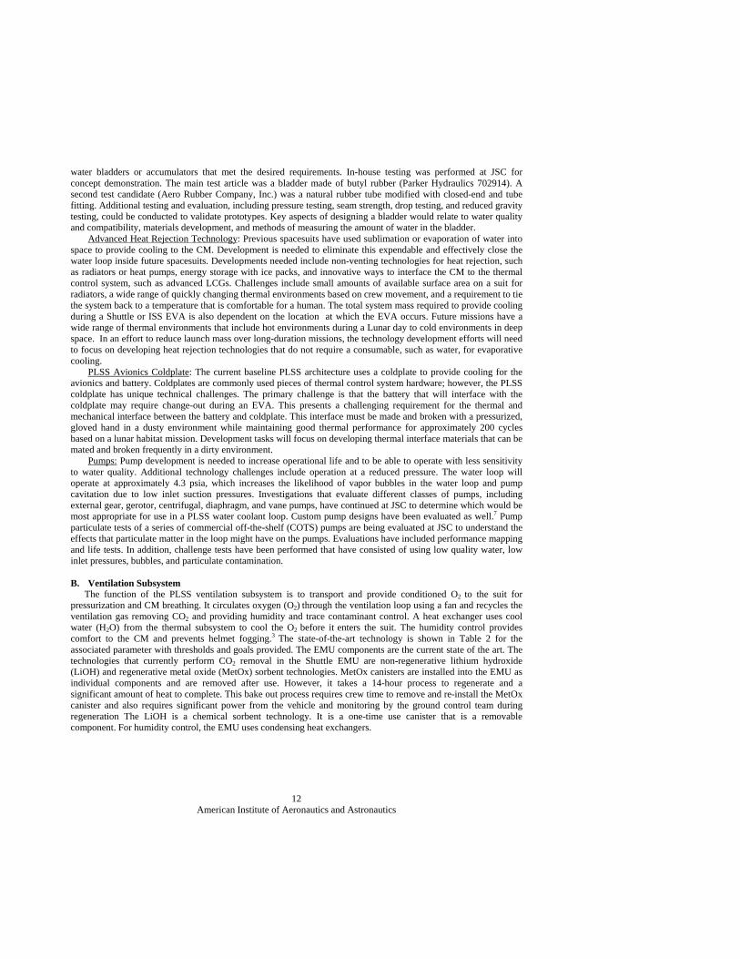
B. Ventilation Subsystem The function of the PLSS ventilation subsystem is to transport and provide conditioned O2 to the suit for pressurization and CM breathing. It circulates oxygen (O2) through the ventilation loop using a fan and recycles the ventilation gas removing CO2 and providing humidity and trace contaminant control. A heat exchanger uses cool water (H2O) from the thermal subsystem to cool the O2 before it enters the suit. The humidity control provides comfort to the CM and prevents helmet fogging.3 The state-of-the-art technology is shown in Table 2 for the associated parameter with thresholds and goals provided. The EMU components are the current state of the art. The technologies that currently perform CO2 removal in the Shuttle EMU are non-regenerative lithium hydroxide (LiOH) and regenerative metal oxide (MetOx) sorbent technologies. MetOx canisters are installed into the EMU as individual components and are removed after use. However, it takes a 14-hour process to regenerate and a significant amount of heat to complete. This bake out process requires crew time to remove and re-install the MetOx canister and also requires significant power from the vehicle and monitoring by the ground control team during regeneration The LiOH is a chemical sorbent technology. It is a one-time use canister that is a removable component. For humidity control, the EMU uses condensing heat exchangers.
American Institute of Aeronautics and Astronautics
13
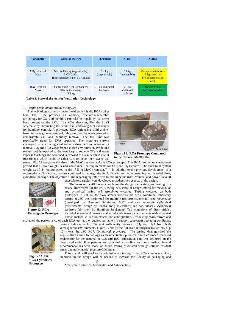
1. Rapid Cycle Amine (RCA) Swing Bed The technology currently under development is the RCA swing bed. The RCA provides an on-back, vacuum-regenerable technology for CO2 and humidity control.This capability has never been present on the EMU. The RCA also simplifies the PLSS schematic by eliminating the need for a condensing heat exchanger for humidity control. A prototype RCA unit using solid amine-based technology was designed, fabricated, and laboratory-tested to demonstrate CO2 and humidity removal. The test unit was specifically sized for EVA operation. The prototype system employed two alternating solid amine sorbent beds to continuously remove CO2 and H2O vapor from a closed environment. While one sorbent bed is exposed to the vent loop to remove CO2 and water vapor (adsorbing), the other bed is exposed to a regeneration circuit (desorbing), which could be either vacuum or an inert sweep gas stream. Fig. 11 compares the sizes of the MetOx system and the RCA prototype. This RCA prototype development proved that a lower-weight design could meet the requirements for CO2 and H2O control. The final total system weight was 3.84 kg, compared to the 15.5-kg MetOx canister.11,12 In addition to the previous development of a rectangular RCA canister, efforts continued to redesign the RCA canister and valve assembly into a radial flow, cylindrical package. The objective of the repackaging effort was to minimize the mass, volume, and power. Several
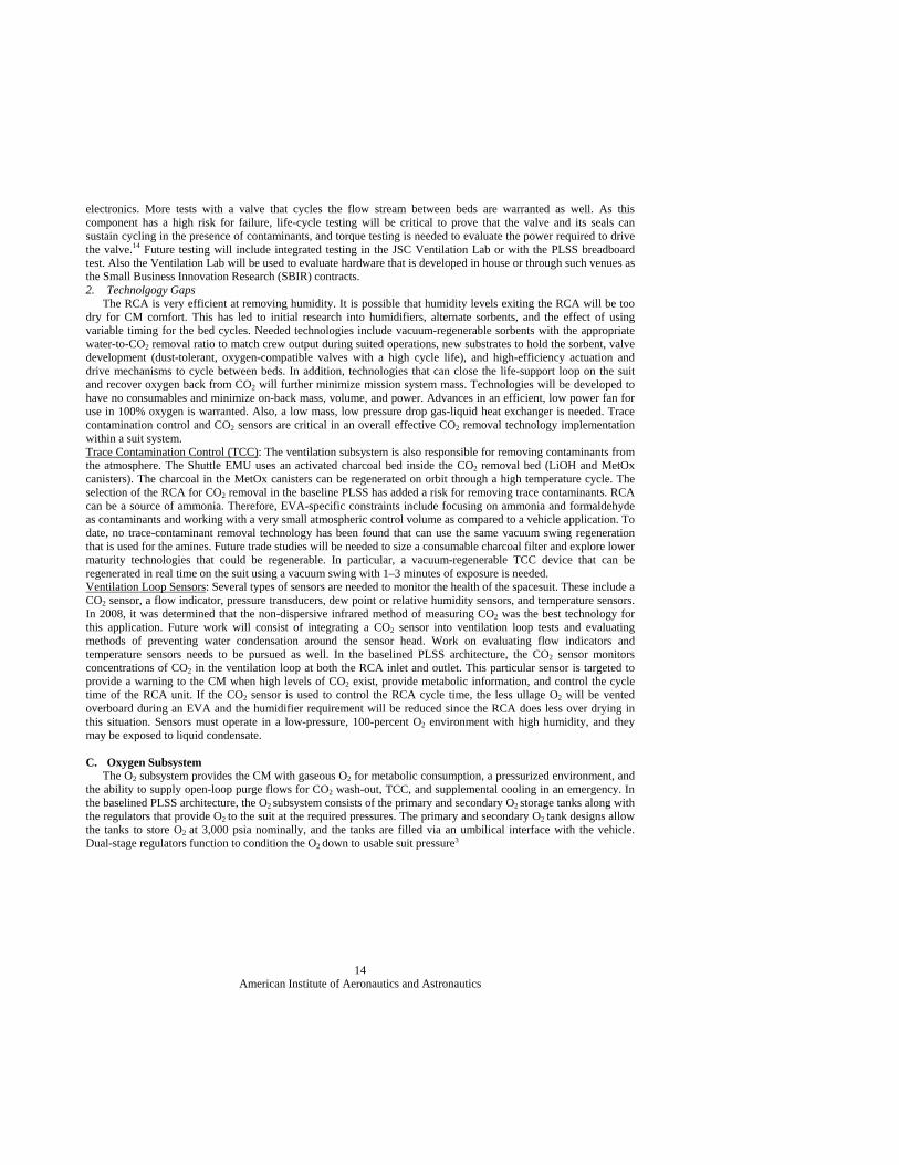
subscale test articles were developed to address key aspects of the design. The focus in FY2011 is on completing the design, fabrication, and testing of a rotary drum valve for the RCA swing bed. Parallel design efforts for rectangular and cylindrical swing bed assemblies occurred. Testing occurred on both prototypes to test out the flow stream between the beds. Additional laboratory testing at JSC was performed for multiple test articles, one full-size rectangular (developed by Hamilton Sundstrand HS)) and one sub-scale cylindrical (experimental design by Jacobs, Inc.) assemblies, and two subscale cylindrical canisters fabricated by Hamilton Sundstrand. Test conditions of these articles included at sea-level pressure and at reduced-pressure environments with simulated human metabolic loads in closed-loop configuration. This testing characterized and
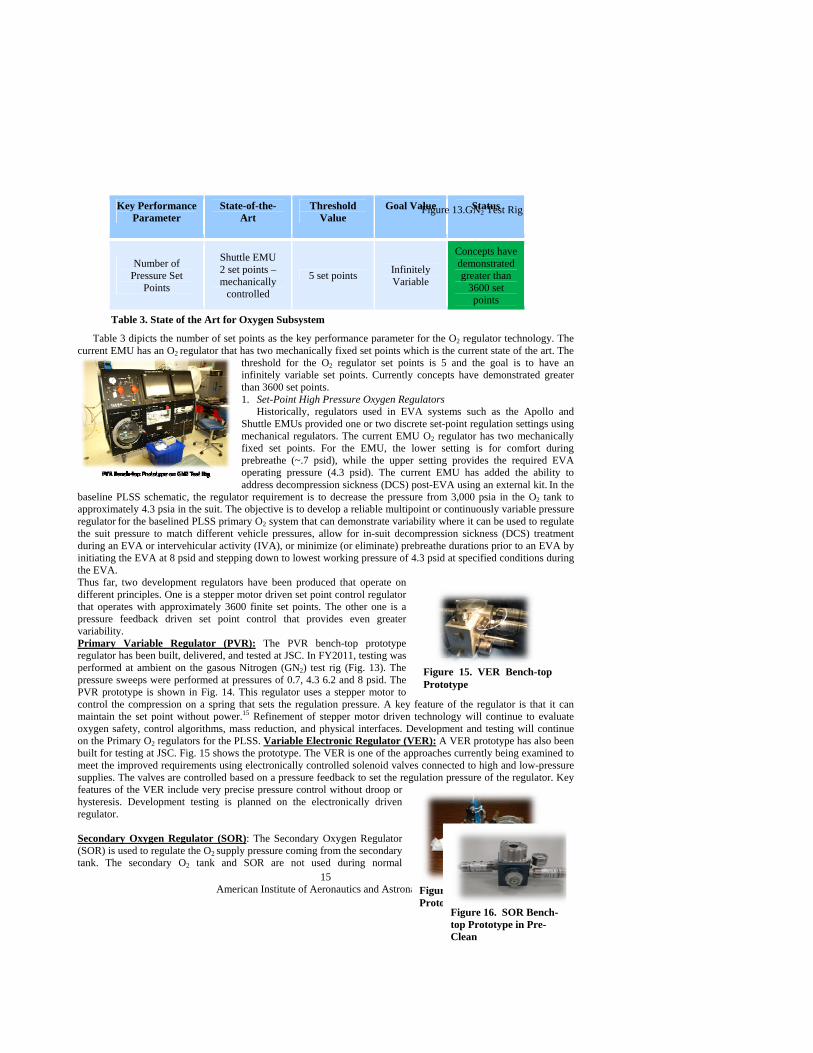
evaluated the performance of each RCA unit at the required portable life support subsystem operating conditions. Resuts indicate each RCA unit sufficiently removed CO2 and H2O from both atmosphereic environments. Figure 12 shows the full scale rectangular test article. Fig. 13 shows the JSC RCA Cylindrical prototype. The testing distinguisthed the regenerative amine technology as an acceptable option for future advanced spacesuit technology for the removal of CO2 and H2O. Substantial data was collected on the linear and radial flow patterns and provided a baseline for future testing. Several recommendations were made on future testing associated with gas stream resident times and outlet partial pressure CO2 limits.13 Future work will need to include full-scale testing of the RCA component. Also, iteration on the design will be needed to increase the fidelity of packaging and
Parameter State-of-the-Art Threshold Goal Status
CO2 Removal Mass
MetOx 15.5 kg (regenerable), LiOH 2.9 kg
(not regenerable, per-EVA mass)
6.2 kg (regenerable)
3.4 kg (regenerable)
Mass prediction of ~ 5 kg based on
preliminary design work
H2O Removal Mass
Condensing Heat Exchangers Shuttle technology
3.3 kg
0 – no additional hardware
0 – no additional hardware
No additional hardware needed
Table 2. State of the Art for Ventilation Technology
Figure 11. RCA Prototype Compared to the Current MetOx Unit
MetOx
Amine System
MetOx
Amine System
Figure 12. RCA Rectangular Prototype
Figure 13. JSC RCA Cylindrical Prototype
American Institute of Aeronautics and Astronautics
14
electronics. More tests with a valve that cycles the flow stream between beds are warranted as well. As this component has a high risk for failure, life-cycle testing will be critical to prove that the valve and its seals can sustain cycling in the presence of contaminants, and torque testing is needed to evaluate the power required to drive the valve.14 Future testing will include integrated testing in the JSC Ventilation Lab or with the PLSS breadboard test. Also the Ventilation Lab will be used to evaluate hardware that is developed in house or through such venues as the Small Business Innovation Research (SBIR) contracts. 2. Technolgogy Gaps The RCA is very efficient at removing humidity. It is possible that humidity levels exiting the RCA will be too dry for CM comfort. This has led to initial research into humidifiers, alternate sorbents, and the effect of using variable timing for the bed cycles. Needed technologies include vacuum-regenerable sorbents with the appropriate water-to-CO2 removal ratio to match crew output during suited operations, new substrates to hold the sorbent, valve development (dust-tolerant, oxygen-compatible valves with a high cycle life), and high-efficiency actuation and drive mechanisms to cycle between beds. In addition, technologies that can close the life-support loop on the suit and recover oxygen back from CO2 will further minimize mission system mass. Technologies will be developed to have no consumables and minimize on-back mass, volume, and power. Advances in an efficient, low power fan for use in 100% oxygen is warranted. Also, a low mass, low pressure drop gas-liquid heat exchanger is needed. Trace contamination control and CO2 sensors are critical in an overall effective CO2 removal technology implementation within a suit system. Trace Contamination Control (TCC): The ventilation subsystem is also responsible for removing contaminants from the atmosphere. The Shuttle EMU uses an activated charcoal bed inside the CO2 removal bed (LiOH and MetOx canisters). The charcoal in the MetOx canisters can be regenerated on orbit through a high temperature cycle. The selection of the RCA for CO2 removal in the baseline PLSS has added a risk for removing trace contaminants. RCA can be a source of ammonia. Therefore, EVA-specific constraints include focusing on ammonia and formaldehyde as contaminants and working with a very small atmospheric control volume as compared to a vehicle application. To date, no trace-contaminant removal technology has been found that can use the same vacuum swing regeneration that is used for the amines. Future trade studies will be needed to size a consumable charcoal filter and explore lower maturity technologies that could be regenerable. In particular, a vacuum-regenerable TCC device that can be regenerated in real time on the suit using a vacuum swing with 1–3 minutes of exposure is needed. Ventilation Loop Sensors: Several types of sensors are needed to monitor the health of the spacesuit. These include a CO2 sensor, a flow indicator, pressure transducers, dew point or relative humidity sensors, and temperature sensors. In 2008, it was determined that the non-dispersive infrared method of measuring CO2 was the best technology for this application. Future work will consist of integrating a CO2 sensor into ventilation loop tests and evaluating methods of preventing water condensation around the sensor head. Work on evaluating flow indicators and temperature sensors needs to be pursued as well. In the baselined PLSS architecture, the CO2 sensor monitors concentrations of CO2 in the ventilation loop at both the RCA inlet and outlet. This particular sensor is targeted to provide a warning to the CM when high levels of CO2 exist, provide metabolic information, and control the cycle time of the RCA unit. If the CO2 sensor is used to control the RCA cycle time, the less ullage O2 will be vented overboard during an EVA and the humidifier requirement will be reduced since the RCA does less over drying in this situation. Sensors must operate in a low-pressure, 100-percent O2 environment with high humidity, and they may be exposed to liquid condensate.
C. Oxygen Subsystem The O2 subsystem provides the CM with gaseous O2 for metabolic consumption, a pressurized environment, and the ability to supply open-loop purge flows for CO2 wash-out, TCC, and supplemental cooling in an emergency. In the baselined PLSS architecture, the O2 subsystem consists of the primary and secondary O2 storage tanks along with the regulators that provide O2 to the suit at the required pressures. The primary and secondary O2 tank designs allow the tanks to store O2 at 3,000 psia nominally, and the tanks are filled via an umbilical interface with the vehicle. Dual-stage regulators function to condition the O2 down to usable suit pressure3
American Institute of Aeronautics and Astronautics
15
Table 3 dipicts the number of set points as the key performance parameter for the O2 regulator technology. The current EMU has an O2 regulator that has two mechanically fixed set points which is the current state of the art. The
threshold for the O2 regulator set points is 5 and the goal is to have an infinitely variable set points. Currently concepts have demonstrated greater than 3600 set points. 1. Set-Point High Pressure Oxygen Regulators Historically, regulators used in EVA systems such as the Apollo and Shuttle EMUs provided one or two discrete set-point regulation settings using mechanical regulators. The current EMU O2 regulator has two mechanically fixed set points. For the EMU, the lower setting is for comfort during prebreathe (~.7 psid), while the upper setting provides the required EVA operating pressure (4.3 psid). The current EMU has added the ability to address decompression sickness (DCS) post-EVA using an external kit. In the
baseline PLSS schematic, the regulator requirement is to decrease the pressure from 3,000 psia in the O2 tank to approximately 4.3 psia in the suit. The objective is to develop a reliable multipoint or continuously variable pressure regulator for the baselined PLSS primary O2 system that can demonstrate variability where it can be used to regulate the suit pressure to match different vehicle pressures, allow for in-suit decompression sickness (DCS) treatment during an EVA or intervehicular activity (IVA), or minimize (or eliminate) prebreathe durations prior to an EVA by
initiating the EVA at 8 psid and stepping down to lowest working pressure of 4.3 psid at specified conditions during the EVA. Thus far, two development regulators have been produced that operate on different principles. One is a stepper motor driven set point control regulator that operates with approximately 3600 finite set points. The other one is a pressure feedback driven set point control that provides even greater variability. Primary Variable Regulator (PVR): The PVR bench-top prototype regulator has been built, delivered, and tested at JSC. In FY2011, testing was performed at ambient on the gasous Nitrogen (GN2) test rig (Fig. 13). The pressure sweeps were performed at pressures of 0.7, 4.3 6.2 and 8 psid. The PVR prototype is shown in Fig. 14. This regulator uses a stepper motor to control the compression on a spring that sets the regulation pressure. A key feature of the regulator is that it can maintain the set point without power.15 Refinement of stepper motor driven technology will continue to evaluate oxygen safety, control algorithms, mass reduction, and physical interfaces. Development and testing will continue on the Primary O2 regulators for the PLSS. Variable Electronic Regulator (VER): A VER prototype has also been built for testing at JSC. Fig. 15 shows the prototype. The VER is one of the approaches currently being examined to meet the improved requirements using electronically controlled solenoid valves connected to high and low-pressure supplies. The valves are controlled based on a pressure feedback to set the regulation pressure of the regulator. Key features of the VER include very precise pressure control without droop or hysteresis. Development testing is planned on the electronically driven regulator. Secondary Oxygen Regulator (SOR): The Secondary Oxygen Regulator (SOR) is used to regulate the O2 supply pressure coming from the secondary tank. The secondary O2 tank and SOR are not used during normal
Figure 14. PVR Bench-top Prototype
Key Performance Parameter
State-of-the-Art
Threshold Value
Goal Value Status
Number of Pressure Set
Points
Shuttle EMU 2 set points – mechanically
controlled
5 set points Infinitely Variable
Concepts have demonstrated greater than
3600 set points
Table 3. State of the Art for Oxygen Subsystem
Figure 13.GN2 Test Rig
Figure 15. VER Bench-top Prototype
Figure 16. SOR Bench-top Prototype in Pre-Clean
American Institute of Aeronautics and Astronautics
16
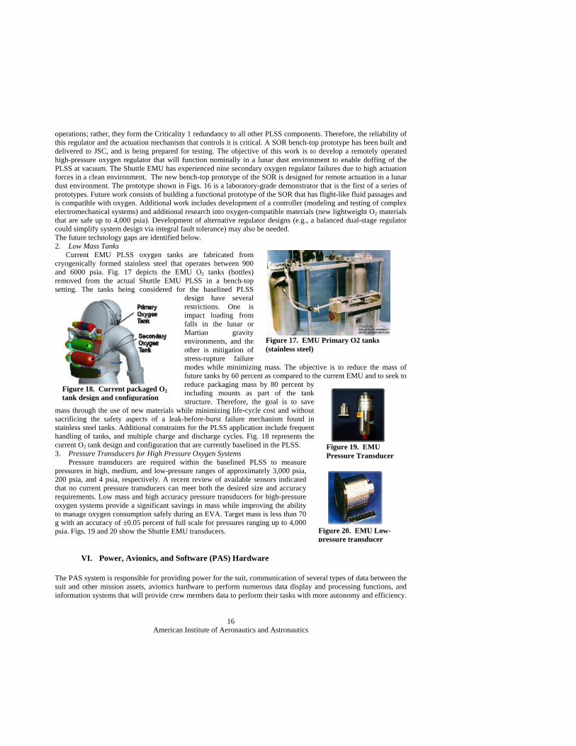
operations; rather, they form the Criticality 1 redundancy to all other PLSS components. Therefore, the reliability of this regulator and the actuation mechanism that controls it is critical. A SOR bench-top prototype has been built and delivered to JSC, and is being prepared for testing. The objective of this work is to develop a remotely operated high-pressure oxygen regulator that will function nominally in a lunar dust environment to enable doffing of the PLSS at vacuum. The Shuttle EMU has experienced nine secondary oxygen regulator failures due to high actuation forces in a clean environment. The new bench-top prototype of the SOR is designed for remote actuation in a lunar dust environment. The prototype shown in Figs. 16 is a laboratory-grade demonstrator that is the first of a series of prototypes. Future work consists of building a functional prototype of the SOR that has flight-like fluid passages and is compatible with oxygen. Additional work includes development of a controller (modeling and testing of complex electromechanical systems) and additional research into oxygen-compatible materials (new lightweight O2 materials that are safe up to 4,000 psia). Development of alternative regulator designs (e.g., a balanced dual-stage regulator could simplify system design via integral fault tolerance) may also be needed. The future technology gaps are identified below. 2. Low Mass Tanks Current EMU PLSS oxygen tanks are fabricated from cryogenically formed stainless steel that operates between 900 and 6000 psia. Fig. 17 depicts the EMU O2 tanks (bottles) removed from the actual Shuttle EMU PLSS in a bench-top setting. The tanks being considered for the baselined PLSS
design have several restrictions. One is impact loading from falls in the lunar or Martian gravity environments, and the other is mitigation of stress-rupture failure modes while minimizing mass. The objective is to reduce the mass of future tanks by 60 percent as compared to the current EMU and to seek to reduce packaging mass by 80 percent by including mounts as part of the tank structure. Therefore, the goal is to save
mass through the use of new materials while minimizing life-cycle cost and without sacrificing the safety aspects of a leak-before-burst failure mechanism found in stainless steel tanks. Additional constraints for the PLSS application include frequent handling of tanks, and multiple charge and discharge cycles. Fig. 18 represents the current O2 tank design and configuration that are currently baselined in the PLSS. 3. Pressure Transducers for High Pressure Oxygen Systems Pressure transducers are required within the baselined PLSS to measure pressures in high, medium, and low-pressure ranges of approximately 3,000 psia, 200 psia, and 4 psia, respectively. A recent review of available sensors indicated that no current pressure transducers can meet both the desired size and accuracy requirements. Low mass and high accuracy pressure transducers for high-pressure oxygen systems provide a significant savings in mass while improving the ability to manage oxygen consumption safely during an EVA. Target mass is less than 70 g with an accuracy of ±0.05 percent of full scale for pressures ranging up to 4,000 psia. Figs. 19 and 20 show the Shuttle EMU transducers.
VI. Power, Avionics, and Software (PAS) Hardware
The PAS system is responsible for providing power for the suit, communication of several types of data between the suit and other mission assets, avionics hardware to perform numerous data display and processing functions, and information systems that will provide crew members data to perform their tasks with more autonomy and efficiency.
Figure 17. EMU Primary O2 tanks (stainless steel)
Figure 18. Current packaged O2 tank design and configuration
Figure 20. EMU Low-pressure transducer
Figure 19. EMU Pressure Transducer
American Institute of Aeronautics and Astronautics
17
Development efforts for PAS systems have been progressing over the last several years. These areas include voice communications, displays, sensor systems, information systems, power systems, and batteries.16
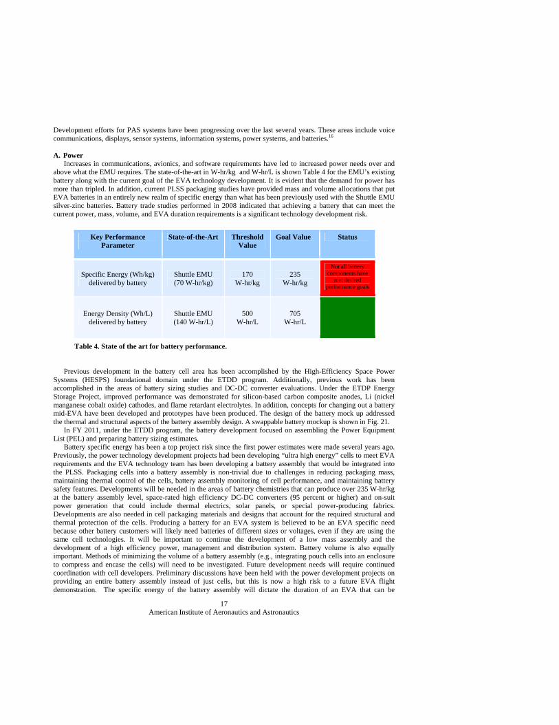
A. Power Increases in communications, avionics, and software requirements have led to increased power needs over and above what the EMU requires. The state-of-the-art in W-hr/kg and W-hr/L is shown Table 4 for the EMU’s existing battery along with the current goal of the EVA technology development. It is evident that the demand for power has more than tripled. In addition, current PLSS packaging studies have provided mass and volume allocations that put EVA batteries in an entirely new realm of specific energy than what has been previously used with the Shuttle EMU silver-zinc batteries. Battery trade studies performed in 2008 indicated that achieving a battery that can meet the current power, mass, volume, and EVA duration requirements is a significant technology development risk.
Table 4. State of the art for battery performance.
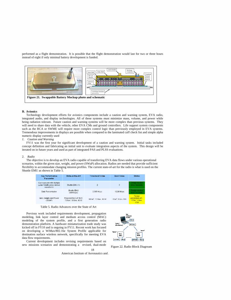
Previous development in the battery cell area has been accomplished by the High-Efficiency Space Power Systems (HESPS) foundational domain under the ETDD program. Additionally, previous work has been accomplished in the areas of battery sizing studies and DC-DC converter evaluations. Under the ETDP Energy Storage Project, improved performance was demonstrated for silicon-based carbon composite anodes, Li (nickel manganese cobalt oxide) cathodes, and flame retardant electrolytes. In addition, concepts for changing out a battery mid-EVA have been developed and prototypes have been produced. The design of the battery mock up addressed the thermal and structural aspects of the battery assembly design. A swappable battery mockup is shown in Fig. 21. In FY 2011, under the ETDD program, the battery development focused on assembling the Power Equipment List (PEL) and preparing battery sizing estimates. Battery specific energy has been a top project risk since the first power estimates were made several years ago. Previously, the power technology development projects had been developing “ultra high energy” cells to meet EVA requirements and the EVA technology team has been developing a battery assembly that would be integrated into the PLSS. Packaging cells into a battery assembly is non-trivial due to challenges in reducing packaging mass, maintaining thermal control of the cells, battery assembly monitoring of cell performance, and maintaining battery safety features. Developments will be needed in the areas of battery chemistries that can produce over 235 W-hr/kg at the battery assembly level, space-rated high efficiency DC-DC converters (95 percent or higher) and on-suit power generation that could include thermal electrics, solar panels, or special power-producing fabrics. Developments are also needed in cell packaging materials and designs that account for the required structural and thermal protection of the cells. Producing a battery for an EVA system is believed to be an EVA specific need because other battery customers will likely need batteries of different sizes or voltages, even if they are using the same cell technologies. It will be important to continue the development of a low mass assembly and the development of a high efficiency power, management and distribution system. Battery volume is also equally important. Methods of minimizing the volume of a battery assembly (e.g., integrating pouch cells into an enclosure to compress and encase the cells) will need to be investigated. Future development needs will require continued coordination with cell developers. Preliminary discussions have been held with the power development projects on providing an entire battery assembly instead of just cells, but this is now a high risk to a future EVA flight demonstration. The specific energy of the battery assembly will dictate the duration of an EVA that can be
Key Performance Parameter
State-of-the-Art Threshold Value
Goal Value Status
Specific Energy (Wh/kg) delivered by battery
Shuttle EMU (70 W-hr/kg)
170 W-hr/kg
235 W-hr/kg
Not all battery components have
met desired performance goals
Energy Density (Wh/L) delivered by battery
Shuttle EMU (140 W-hr/L)
500 W-hr/L
705 W-hr/L
American Institute of Aeronautics and Astronautics
18
performed as a flight demonstration. It is possible that the flight demonstration would last for two or three hours instead of eight if only minimal battery development is funded.
B. Avionics Technology development efforts for avionics components include a caution and warning system, EVA radio, integrated audio, and display technologies. All of these systems must minimize mass, volume, and power while being radiation tolerant. Future caution and warning systems will be more complex than previous systems. They will need to share data with the vehicle, other EVA CMs and ground controllers. Life support system components such as the RCA or SWME will require more complex control logic than previously employed in EVA systems. Tremendous improvements in displays are possible when compared to the laminated cuff check list and simple alpha numeric display currently used 1. Caution and Warning FY11 was the first year for significant development of a caution and warning system. Initial tasks included concept definition and fabricating an initial unit to evaluate integration aspects of the system. This design will be iterated on in future years and used as part of integrated PAS and PLSS evaluations. 2. Radio The objective is to develop an EVA radio capable of transferring EVA data flows under various operational scenarios, within the given size, weight, and power (SWaP) allocation. Radios are needed that provide sufficient flexibility to accommodate changing mission profiles. The current state-of-art for the radio is what is used on the Shuttle EMU as shown in Table 5.
Previous work included requirements development, propagation modeling, link layer control and medium access control (MAC) modeling of the system profile, and a first generation radio demonstration platform. A hardware miniaturization trade study was kicked off in FY10 and is ongoing in FY11. Recent work has focused on developing a WiMax/802.16e System Profile applicable for destination surface wireless network, specifically for meeting EVA data flow requirements. Current development includes revising requirements based on new missions scenarios and demonstrating a revised, dual-mode
Table 5. Radio Advances over the State of Art
Figure 21. Swappable Battery Mockup photo and schematic
Inner Shell Outer Shell
Latch Handle Recharge Connector
Compliant Thermal Interface Material
8P Cell Module
Interface Plate
Cold Plate Simulator(4 to 32°C)
Figure 22. Radio Block Diagream
American Institute of Aeronautics and Astronautics
19
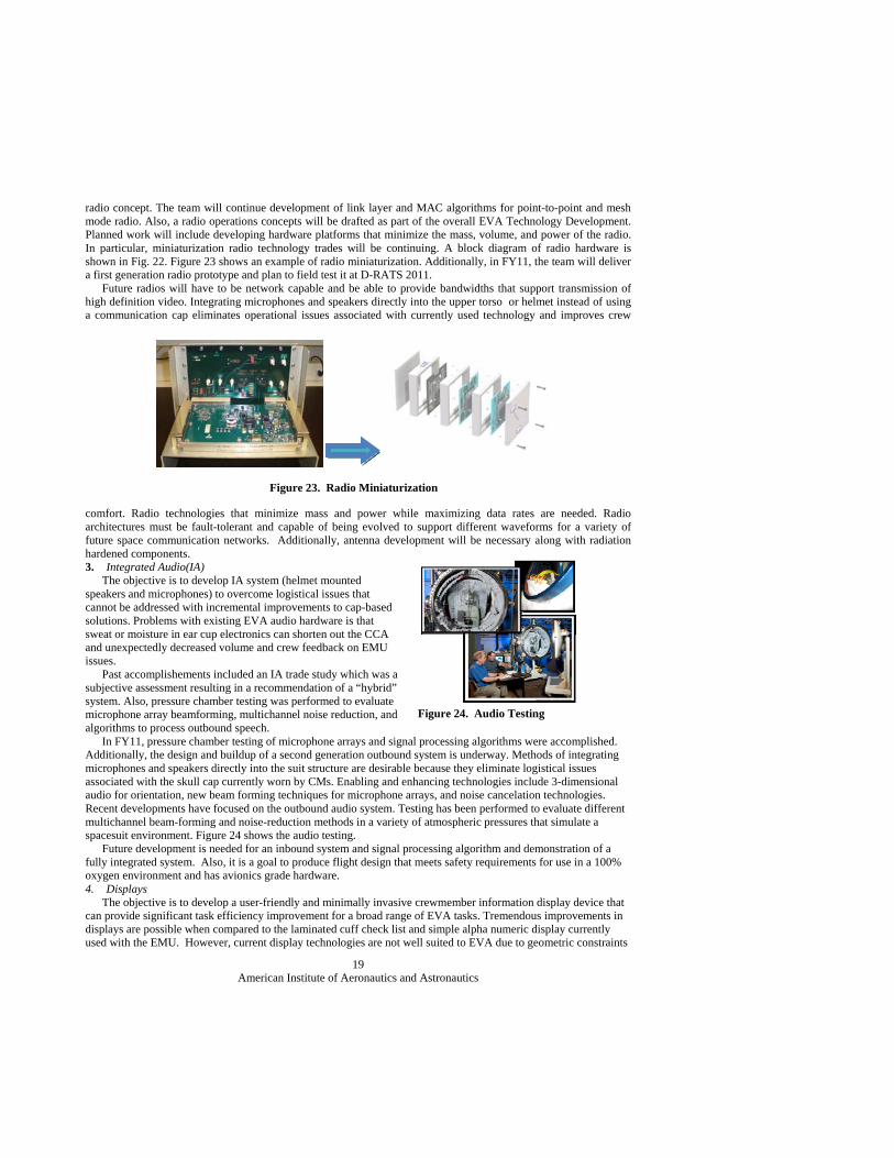
radio concept. The team will continue development of link layer and MAC algorithms for point-to-point and mesh mode radio. Also, a radio operations concepts will be drafted as part of the overall EVA Technology Development. Planned work will include developing hardware platforms that minimize the mass, volume, and power of the radio. In particular, miniaturization radio technology trades will be continuing. A block diagram of radio hardware is shown in Fig. 22. Figure 23 shows an example of radio miniaturization. Additionally, in FY11, the team will deliver a first generation radio prototype and plan to field test it at D-RATS 2011. Future radios will have to be network capable and be able to provide bandwidths that support transmission of high definition video. Integrating microphones and speakers directly into the upper torso or helmet instead of using a communication cap eliminates operational issues associated with currently used technology and improves crew
comfort. Radio technologies that minimize mass and power while maximizing data rates are needed. Radio architectures must be fault-tolerant and capable of being evolved to support different waveforms for a variety of future space communication networks. Additionally, antenna development will be necessary along with radiation hardened components. 3. Integrated Audio(IA) The objective is to develop IA system (helmet mounted speakers and microphones) to overcome logistical issues that cannot be addressed with incremental improvements to cap-based solutions. Problems with existing EVA audio hardware is that sweat or moisture in ear cup electronics can shorten out the CCA and unexpectedly decreased volume and crew feedback on EMU issues. Past accomplishements included an IA trade study which was a subjective assessment resulting in a recommendation of a “hybrid” system. Also, pressure chamber testing was performed to evaluate microphone array beamforming, multichannel noise reduction, and algorithms to process outbound speech. In FY11, pressure chamber testing of microphone arrays and signal processing algorithms were accomplished. Additionally, the design and buildup of a second generation outbound system is underway. Methods of integrating microphones and speakers directly into the suit structure are desirable because they eliminate logistical issues associated with the skull cap currently worn by CMs. Enabling and enhancing technologies include 3-dimensional audio for orientation, new beam forming techniques for microphone arrays, and noise cancelation technologies. Recent developments have focused on the outbound audio system. Testing has been performed to evaluate different multichannel beam-forming and noise-reduction methods in a variety of atmospheric pressures that simulate a spacesuit environment. Figure 24 shows the audio testing. Future development is needed for an inbound system and signal processing algorithm and demonstration of a fully integrated system. Also, it is a goal to produce flight design that meets safety requirements for use in a 100% oxygen environment and has avionics grade hardware. 4. Displays The objective is to develop a user-friendly and minimally invasive crewmember information display device that can provide significant task efficiency improvement for a broad range of EVA tasks. Tremendous improvements in displays are possible when compared to the laminated cuff check list and simple alpha numeric display currently used with the EMU. However, current display technologies are not well suited to EVA due to geometric constraints
Figure 23. Radio Miniaturization
Figure 24. Audio Testing
American Institute of Aeronautics and Astronautics
20
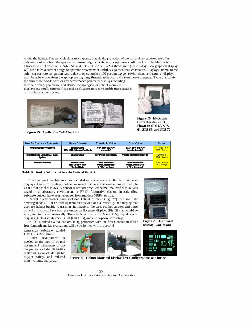
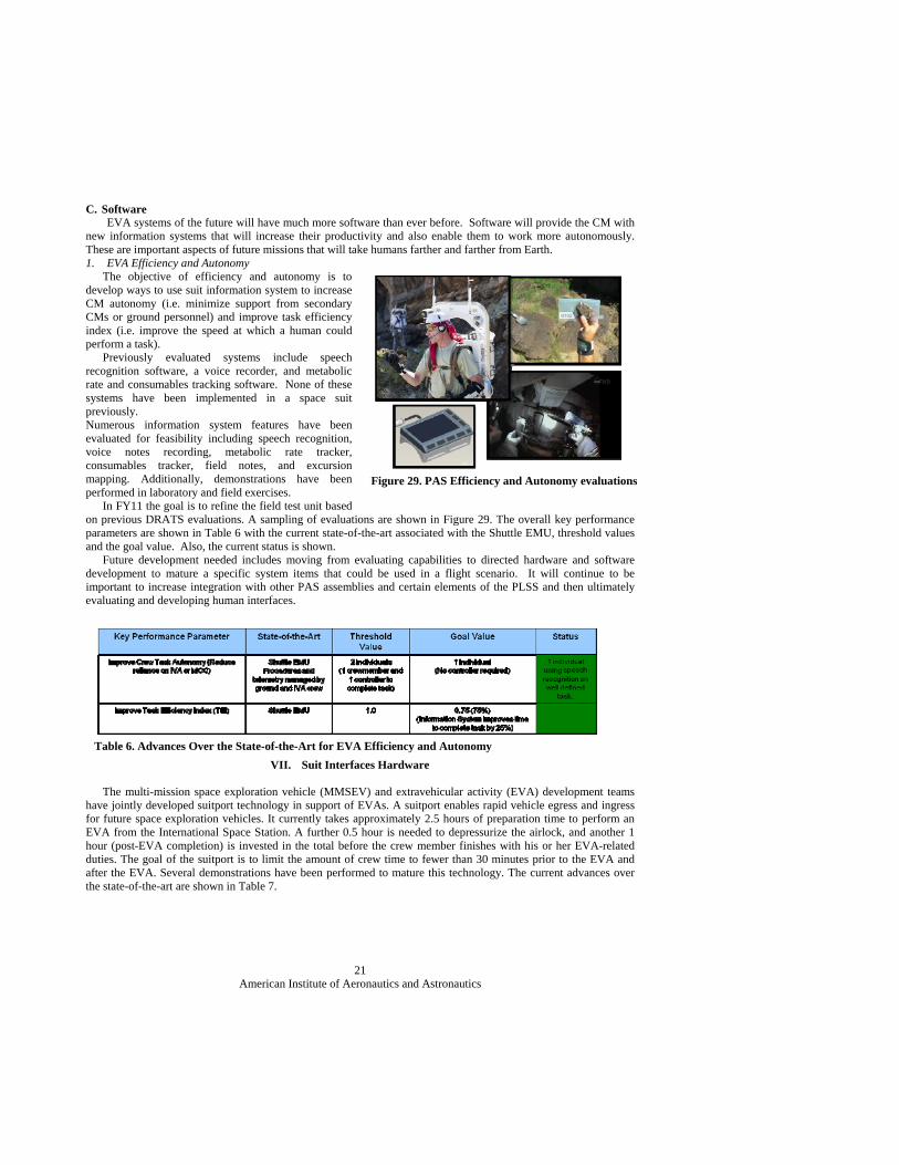
within the helmet. Flat panel displays must operate outside the protection of the suit and are expected to suffer deleterious effects from the space environment. Figure 25 shows the Apollo-era cuff checklist. The Electronic Cuff Checklist (ECC) flown on STS-63, STS-64, STS-69, and STS-72 is shown in Figure 26. Any EVA graphical display will need to be a custom design to optimize crewmember usability against SWaP constraints. Displays internal to the suit must not pose an ignition hazard due to operation in a 100-percent oxygen environment, and external displays must be able to operate in the appropriate lighting, thermal, radiation, and vacuum environments. Table 5 indicates the current state-of-the-art for key performance parameter displays including threshold value, goal value, and status. Technologies for helmet-mounted displays and small, external flat-panel displays are needed to enable more capable on-suit information systems.
Previous work in this area has included extensive trade studies for flat panel displays, heads up displays, helmet mounted displays, and evaluations of multiple COTS flat panel displays. A vendor (Luminit) procured helmet mounted display was tested in a laboratory environment in FY10. Alternative designs (mosaic tiles, substrate guided) have been leveraged from multiple SBIRs awarded Recent developments have included helmet displays (Fig. 27) that use light emitting diode (LED) or laser light sources as well as a substrate guided display that uses the helmet bubble to transmit the image to the CM. Market surveys and basic optical evaluations have been performed on flat-panel displays (Fig. 28) that could be integrated into a suit externally. These include organic LEDs (OLEDs), liquid crystal displays (LCDs), cholesteric LCDs (ChLCDs), and electrophoretic displays. In FY11, suited evaluations are being performed with the first Generation HMD from Luminit and lab evaluations will be performed with the second
generation substrate guided HMD (SBIR/Luminit). Future development is needed in the area of optical design and refinement of the design to include flight-like materials, avionics, design for oxygen safety, and reduced mass, volume, and power.
Figure 25. Apollo Era Cuff Checklist
Figure 26. Electronic Cuff Checklist (ECC) Flown on STS-63, STS-64, STS-69, and STS-72
Table 5. Display Advances Over the State of the Art
Figure 28. Flat Panel Display Evaluations
Figure 27. Helmet Mounted Display Test Configurations and image
American Institute of Aeronautics and Astronautics
21
C. Software EVA systems of the future will have much more software than ever before. Software will provide the CM with
new information systems that will increase their productivity and also enable them to work more autonomously. These are important aspects of future missions that will take humans farther and farther from Earth. 1. EVA Efficiency and Autonomy The objective of efficiency and autonomy is to develop ways to use suit information system to increase CM autonomy (i.e. minimize support from secondary CMs or ground personnel) and improve task efficiency index (i.e. improve the speed at which a human could perform a task). Previously evaluated systems include speech recognition software, a voice recorder, and metabolic rate and consumables tracking software. None of these systems have been implemented in a space suit previously. Numerous information system features have been evaluated for feasibility including speech recognition, voice notes recording, metabolic rate tracker, consumables tracker, field notes, and excursion mapping. Additionally, demonstrations have been performed in laboratory and field exercises. In FY11 the goal is to refine the field test unit based on previous DRATS evaluations. A sampling of evaluations are shown in Figure 29. The overall key performance parameters are shown in Table 6 with the current state-of-the-art associated with the Shuttle EMU, threshold values and the goal value. Also, the current status is shown. Future development needed includes moving from evaluating capabilities to directed hardware and software development to mature a specific system items that could be used in a flight scenario. It will continue to be important to increase integration with other PAS assemblies and certain elements of the PLSS and then ultimately evaluating and developing human interfaces.
VII. Suit Interfaces Hardware
The multi-mission space exploration vehicle (MMSEV) and extravehicular activity (EVA) development teams have jointly developed suitport technology in support of EVAs. A suitport enables rapid vehicle egress and ingress for future space exploration vehicles. It currently takes approximately 2.5 hours of preparation time to perform an EVA from the International Space Station. A further 0.5 hour is needed to depressurize the airlock, and another 1 hour (post-EVA completion) is invested in the total before the crew member finishes with his or her EVA-related duties. The goal of the suitport is to limit the amount of crew time to fewer than 30 minutes prior to the EVA and after the EVA. Several demonstrations have been performed to mature this technology. The current advances over the state-of-the-art are shown in Table 7.
Table 6. Advances Over the State-of-the-Art for EVA Efficiency and Autonomy
Figure 29. PAS Efficiency and Autonomy evaluations
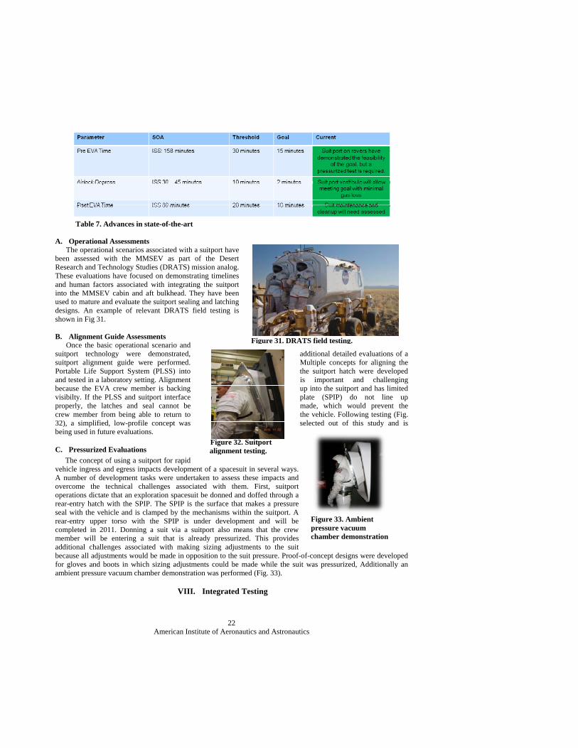
American Institute of Aeronautics and Astronautics
22
Table 7. Advances in state-of-the-art
A. Operational Assessments The operational scenarios associated with a suitport have been assessed with the MMSEV as part of the Desert Research and Technology Studies (DRATS) mission analog. These evaluations have focused on demonstrating timelines and human factors associated with integrating the suitport into the MMSEV cabin and aft bulkhead. They have been used to mature and evaluate the suitport sealing and latching designs. An example of relevant DRATS field testing is shown in Fig 31. B. Alignment Guide Assessments Once the basic operational scenario and suitport technology were demonstrated, additional detailed evaluations of a suitport alignment guide were performed. Multiple concepts for aligning the Portable Life Support System (PLSS) into the suitport hatch were developed and tested in a laboratory setting. Alignment is important and challenging because the EVA crew member is backing up into the suitport and has limited visibilty. If the PLSS and suitport interface plate (SPIP) do not line up properly, the latches and seal cannot be made, which would prevent the crew member from being able to return to the vehicle. Following testing (Fig. 32), a simplified, low-profile concept was selected out of this study and is being used in future evaluations.
C. Pressurized Evaluations
The concept of using a suitport for rapid vehicle ingress and egress impacts development of a spacesuit in several ways. A number of development tasks were undertaken to assess these impacts and overcome the technical challenges associated with them. First, suitport operations dictate that an exploration spacesuit be donned and doffed through a rear-entry hatch with the SPIP. The SPIP is the surface that makes a pressure seal with the vehicle and is clamped by the mechanisms within the suitport. A rear-entry upper torso with the SPIP is under development and will be completed in 2011. Donning a suit via a suitport also means that the crew member will be entering a suit that is already pressurized. This provides additional challenges associated with making sizing adjustments to the suit because all adjustments would be made in opposition to the suit pressure. Proof-of-concept designs were developed for gloves and boots in which sizing adjustments could be made while the suit was pressurized, Additionally an ambient pressure vacuum chamber demonstration was performed (Fig. 33).
VIII. Integrated Testing
Figure 31. DRATS field testing.
Figure 32. Suitport alignment testing.
Figure 33. Ambient pressure vacuum chamber demonstration
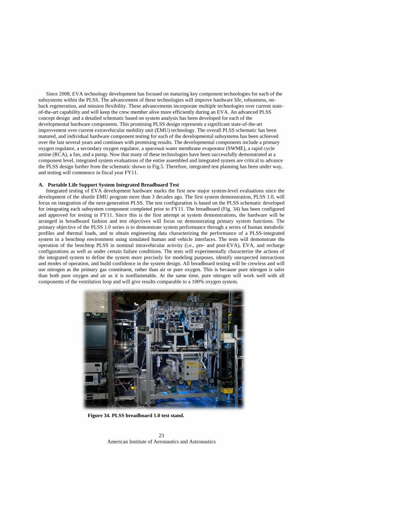
American Institute of Aeronautics and Astronautics
23
Since 2008, EVA technology development has focused on maturing key component technologies for each of the subsystems within the PLSS. The advancement of these technologies will improve hardware life, robustness, on-back regeneration, and mission flexibility. These advancements incorporate multiple technologies over current state-of-the-art capability and will keep the crew member alive more efficiently during an EVA. An advanced PLSS concept design and a detailed schematic based on system analysis has been developed for each of the developmental hardware components. This promising PLSS design represents a significant state-of-the-art improvement over current extravehicular mobility unit (EMU) technology. The overall PLSS schematic has been matured, and individual hardware component testing for each of the developmental subsystems has been achieved over the last several years and continues with promising results. The developmental components include a primary oxygen regulator, a secondary oxygen regulator, a spacesuit water membrane evaporator (SWME), a rapid cycle amine (RCA), a fan, and a pump. Now that many of these technologies have been successfully demonstrated at a component level, integrated system evaluations of the entire assembled and integrated system are critical to advance the PLSS design further from the schematic shown in Fig.5. Therefore, integrated test planning has been under way, and testing will commence in fiscal year FY11. A. Portable Life Support System Integrated Breadboard Test Integrated testing of EVA development hardware marks the first new major system-level evaluations since the development of the shuttle EMU program more than 3 decades ago. The first system demonstration, PLSS 1.0, will focus on integration of the next-generation PLSS. The test configuration is based on the PLSS schematic developed for integrating each subsystem component completed prior to FY11. The breadboard (Fig. 34) has been configured and approved for testing in FY11. Since this is the first attempt at system demonstrations, the hardware will be arranged in breadboard fashion and test objectives will focus on demonstrating primary system functions. The primary objective of the PLSS 1.0 series is to demonstrate system performance through a series of human metabolic profiles and thermal loads, and to obtain engineering data characterizing the performance of a PLSS-integrated system in a benchtop environment using simulated human and vehicle interfaces. The tests will demonstrate the operation of the benchtop PLSS in nominal intravehicular activity (i.e., pre- and post-EVA), EVA, and recharge configurations as well as under certain failure conditions. The tests will experimentally characterize the actions of the integrated system to define the system more precisely for modeling purposes, identify unexpected interactions and modes of operation, and build confidence in the system design. All breadboard testing will be crewless and will use nitrogen as the primary gas constituent, rather than air or pure oxygen. This is because pure nitrogen is safer than both pure oxygen and air as it is nonflammable. At the same time, pure nitrogen will work well with all components of the ventilation loop and will give results comparable to a 100% oxygen system.
Figure 34. PLSS breadboard 1.0 test stand.
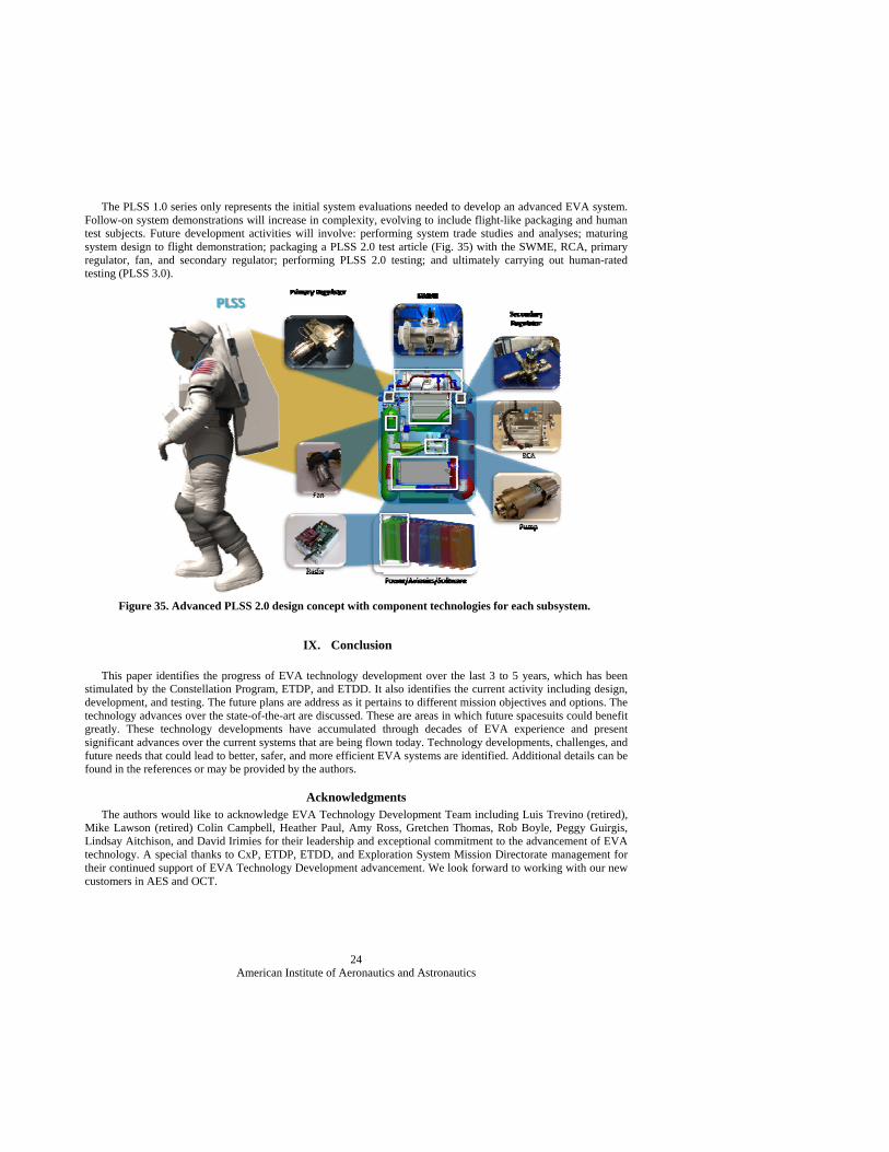
American Institute of Aeronautics and Astronautics
24
The PLSS 1.0 series only represents the initial system evaluations needed to develop an advanced EVA system. Follow-on system demonstrations will increase in complexity, evolving to include flight-like packaging and human test subjects. Future development activities will involve: performing system trade studies and analyses; maturing system design to flight demonstration; packaging a PLSS 2.0 test article (Fig. 35) with the SWME, RCA, primary regulator, fan, and secondary regulator; performing PLSS 2.0 testing; and ultimately carrying out human-rated testing (PLSS 3.0).
IX. Conclusion This paper identifies the progress of EVA technology development over the last 3 to 5 years, which has been
stimulated by the Constellation Program, ETDP, and ETDD. It also identifies the current activity including design, development, and testing. The future plans are address as it pertains to different mission objectives and options. The technology advances over the state-of-the-art are discussed. These are areas in which future spacesuits could benefit greatly. These technology developments have accumulated through decades of EVA experience and present significant advances over the current systems that are being flown today. Technology developments, challenges, and future needs that could lead to better, safer, and more efficient EVA systems are identified. Additional details can be found in the references or may be provided by the authors.
Acknowledgments The authors would like to acknowledge EVA Technology Development Team including Luis Trevino (retired),
Mike Lawson (retired) Colin Campbell, Heather Paul, Amy Ross, Gretchen Thomas, Rob Boyle, Peggy Guirgis, Lindsay Aitchison, and David Irimies for their leadership and exceptional commitment to the advancement of EVA technology. A special thanks to CxP, ETDP, ETDD, and Exploration System Mission Directorate management for their continued support of EVA Technology Development advancement. We look forward to working with our new customers in AES and OCT.
Figure 35. Advanced PLSS 2.0 design concept with component technologies for each subsystem.
American Institute of Aeronautics and Astronautics
25
References 1Haldane, J. S., Ridge, M. E., Post, W., Colley, R., Gagarin, Y. A., Shepard, A. B., Leonow, A., White, E. H., Armstrong, N.
A., Kosmo, J., and Vykukal, H., “The Development of Spacesuits,” USA in Space, edited by F. N. Magill, and R. R. Tobias, Salem Press, Inc., Pasadena, CA, 1996, pp. 731-734.
2Young, A., “Spacesuits, The Smithsonian National Air and Space Museum Collection”, Power House Books, Brooklyn, NY, 2009, Chaps. 8, 9.
3Conger, B., Chullen, C., Barnes, B., Leavitt, G., “Proposed Schematic for an Advanced Development Lunar Portable Life Support System,” 40th International Conference on Environmental Systems, AIAA-2010-6038, Barcelona, Spain, July 2010.
4Kosmo, J.J., “Design Considerationtions for Future Planetary Space Suits”, 20th Intersociety Conference on Environmental Systems, SAE 901428, Williamsburg,Virginia, July 1990.
5”National Aeronautics and Space Administration Authorization Act of 2010”, .PUBLIC LAW 111–267—OCT. 11, 2010, URL: http://legislative.nasa.gov/PL%20111-267.pdf[cited,[June 28, 2010]
6“NATIONAL SPACE POLICY of the UNITED STATES of AMERICA”, [online policy], URL: http://www.whitehouse.gov/sites/default/files/national_space_policy_6-28-10.pdf [cited 28 June, 2010].
7Mitchell, K.C ”Phase VI Glove Durability Testing”, 41st International Conference on Environmental Systems, AIAA-2011, (submitted for publication), Portland, Oregon, July 2011.
8Vogel, M., Vonau, W., Trevino, L., and Bue, G., “Sheet Membrane Spacesuit Water Membrane Evaporator Design and Thermal Tests”, 40th International Conference on Environmental Systems, AIAA-2010-6039, Barcelona, Spain, July 2010.
9Bue, G, Trevino, L., Tsioulos, G., Settles, J., Colunga, A., Vogel, M., and Vonau, W., “Hollow Fiber Spacesuit Water Membrane Evaporator Development and Testing for Advanced Spacesuits”, 40th International Conference on Environmental Systems, AIAA-2010-6040, Barcelona, Spain, July 2010.
10Technology Readiness Level (TRL) Definitions”, [online definitions], URL: http://www.nasa.gov/pdf/458490main_TRL_Definitions.pdf [cited July, 2010]. 11Papale, W., H. Paul, and G. Thomas, “Development of Pressure Swing Adsorption Technology for Spacesuit Carbon Dioxide and Humidity Removal,” 36th International Conference on Environmental Systems, SAE Paper Number 2006-01-2203, 2006.
12Papale, W. and Paul, H., “Development Status of an EVA-sized Cycling Amine Bed System for Spacesuit Carbon Dioxide and Humidity Removal”, 37th International Conference on Environmental Systems, SAE Paper Number 2007-01-3272, July 2007.
13 McMillin, S., Broerman, C., Swickrath, M., and Anderson, M.,“Testing and Results of Vacuum Swing Adsorption Units for Spacesuit Carbon Dioxide and Humidity Control”, 41st Conference on Environmental Systems, AIAA-2011 (submitted for publication), Portland, Oregon, July 2011.
14Paul, H., and Rivera, F., “Space Suit Portable Life Support System Rapid Cycle Amine Repackaging and Sub-Scale Test Results”, 40th International Conference on Environmental Systems, AIAA-2010-6066, Barcelona, Spain, July 2010.
15Mosler, M., and Campbell, C., “Design and Testing of a Variable Pressure Regulator for a Flexible Space Suit Architecture”, 40th International Conference on Environmental Systems, AIAA-2010-6064, Barcelona, Spain, July 2010.
16Malarik, D., Carek, D., Manzo, M., Camperchioli, W., Hunter, G., Lichter, M. and Downey, A., “Concepts for Advanced Extravehicular Activity Systems to Support NASA's Vision for Space Exploration”, 44th AIAA Aerospace Sciences Meeting and Exhibit, AIAA-2006-348, Reno, Nevada, Jan., 2006.