Embed Size (px)
Citation preview

Extreme Networks E4G Series Routers Hardware Installation Guide
Extreme Networks, Inc.3585 Monroe StreetSanta Clara, California 95051(888) 257-3000(408) 579-2800
http://www.extremenetworks.com
Published: January 2013Part number: 120728-00 Rev. 03

AccessAdapt, Alpine, Altitude, BlackDiamond, Direct Attach, EPICenter, ExtremeWorks Essentials, Ethernet Everywhere, Extreme Enabled, Extreme Ethernet Everywhere, Extreme Networks, Extreme Standby Router Protocol, Extreme Turbodrive, Extreme Velocity, ExtremeWare, ExtremeWorks, ExtremeXOS, Go Purple Extreme Solution, ExtremeXOS ScreenPlay, ReachNXT, Ridgeline, Sentriant, ServiceWatch, Summit, SummitStack, Triumph, Unified Access Architecture, Unified Access RF Manager, UniStack, XNV, the Extreme Networks logo, the Alpine logo, the BlackDiamond logo, the Extreme Turbodrive logo, the Summit logos, and the Powered by ExtremeXOS logo are trademarks or registered trademarks of Extreme Networks, Inc. or its subsidiaries in the United States and/or other countries.
sFlow is the property of InMon Corporation.
Specifications are subject to change without notice.
All other registered trademarks, trademarks, and service marks are property of their respective owners.
© 2013 Extreme Networks, Inc. All Rights Reserved.
E4G Series Routers Hardware Installation Guide
2
Contents
Preface.........................................................................................................................................................7
Audience ..................................................................................................................................................................7Conventions .............................................................................................................................................................8Related Publications.................................................................................................................................................8
PART 1: ABOUT THE E4G SERIES ROUTERS
Chapter 1: About the E4G Series Routers .............................................................................................13
Overview ................................................................................................................................................................13E4G-200 Series Cell Site Routers ..........................................................................................................................14
E4G-200 Cell Site Router Overview................................................................................................................14E4G-200-12x Cell Site Router Overview.........................................................................................................15E4G-200 Series Alarms Interface ...................................................................................................................16E4G-200 Series Power Supply .......................................................................................................................16E4G-200 Series CLK Module..........................................................................................................................17E4G-200 Series F16T1E1 Module ..................................................................................................................17E4G-200 Series LEDs.....................................................................................................................................18E4G-200-12x LEDs .........................................................................................................................................19
E4G-400 Cell Site Aggregation Router...................................................................................................................20Combination Ports on the E4G-400 Router ....................................................................................................22LEDs ...............................................................................................................................................................22Power Supplies for the E4G-400.....................................................................................................................24Optional Ports for the E4G-400 Router ...........................................................................................................25
XGM3S-2sf Option Card ..........................................................................................................................25XGM3S-2xf Option Card ..........................................................................................................................26XGM3SB-4sf Option Card........................................................................................................................26E4G-B16T1E1 Option Card .....................................................................................................................26
Pluggable Interfaces for E4G Series Routers.........................................................................................................28
PART 2: INSTALLING HARDWARE
Chapter 2: Site Preparation .....................................................................................................................31
Planning Your Site..................................................................................................................................................32Meeting Site Requirements ....................................................................................................................................32
Operating Environment Requirements ............................................................................................................32Building and Electrical Codes ..................................................................................................................32Equipment Location Considerations ........................................................................................................33Temperature ............................................................................................................................................34Humidity ...................................................................................................................................................34Spacing Requirements and Airflow..........................................................................................................34Electrostatic Discharge ............................................................................................................................35
Rack and Cabinet Specifications and Recommendations...............................................................................35Mechanical Recommendations for the Rack............................................................................................35Protective Grounding for the Rack...........................................................................................................36Space Requirements for an E4G-400 Router ..........................................................................................36Securing the Rack....................................................................................................................................36
Outdoor Installation Sites ................................................................................................................................37Evaluating and Meeting Cable Requirements ........................................................................................................37
E4G Series Routers Hardware Installation Guide
3
Contents
Cabling Standards...........................................................................................................................................38Cable Labeling and Record Keeping ..............................................................................................................38Installing Cable................................................................................................................................................38
Fiber Optic Cable .....................................................................................................................................40Cable Distances.......................................................................................................................................41
RJ-45 Connector Jackets................................................................................................................................42Radio Frequency Interference.........................................................................................................................42
Meeting Power Requirements ................................................................................................................................43Power Supply Requirements...........................................................................................................................43AC Power Cables............................................................................................................................................43Uninterruptible Power Supply Requirements ..................................................................................................44
Selecting a UPS.......................................................................................................................................44Calculating Volt-Amperage Requirements ...............................................................................................44UPS Transition Time................................................................................................................................45
DC Power Requirements ................................................................................................................................45Applicable Industry Standards................................................................................................................................45
Chapter 3: Installing an E4G Series Router ...........................................................................................47
Pre-installation Requirements ................................................................................................................................47Installing the E4G-200 Series Cell Site Routers.....................................................................................................48
Installing the Router in the Rack .....................................................................................................................49Grounding the Router......................................................................................................................................50Preparing the DC Power Input Cable..............................................................................................................51Connecting the Router to DC Power ...............................................................................................................52Installing and Connecting a Clock Module ......................................................................................................53
Connecting Timing Cables to the E4G-200 Series Router.......................................................................54Installing a T1/E1 Module................................................................................................................................54Connecting the Alarms Cable .........................................................................................................................55
Installing the E4G-400 Cell Site Aggregation Router .............................................................................................56Mid-Mounting an E4G-400 Router in a Two-Post Rack ..................................................................................57Front-Mounting an E4G-400 Router in a Two-Post Rack................................................................................58Installing an AC Power Supply........................................................................................................................59Installing a DC Power Supply..........................................................................................................................60
Preparing the DC Cables .........................................................................................................................60Installing the DC Power Supply ...............................................................................................................61Connecting the Ground Wire ...................................................................................................................62
Connecting the Power Supply to the DC Source Voltage ...............................................................................63Connecting the Model 10933 DC power supply to a +24V source ..........................................................64Connecting the Model 10933 or 10934A DC power supply to a -48V source..........................................65
Installing Port Option Cards ............................................................................................................................67Connecting Timing Cables to the E4G-400 Router .........................................................................................69Connecting Cables to the E4G-B16T1E1 Module...........................................................................................69
Initial Startup ..........................................................................................................................................................71Initial Management Access ....................................................................................................................................71
Connecting Equipment to the Console Port ....................................................................................................71Logging In for the First Time ...........................................................................................................................71
PART 3: MAINTENANCE
Chapter 4: Maintenance Procedures ......................................................................................................75
Replacing an AC Power Supply in the E4G-400 Router ........................................................................................75Replacing a DC Power Supply in the E4G-400 Router ..........................................................................................78
Removing the Power Supply...........................................................................................................................78Installing the Replacement Power Supply.......................................................................................................79Connecting the Ground Wire...........................................................................................................................80Connecting the Power Supply to the DC Source Voltage ...............................................................................80
Connecting the Model 10933 DC power supply to a +24V source ..........................................................81
E4G Series Routers Hardware Installation Guide
4
Contents
Connecting the Model 10933 or 10934A DC power supply to a -48V source..........................................83Replacing a Fan Module in the E4G-400 Router....................................................................................................86Replacing Optional Ports in the E4G-400 Router...................................................................................................87Replacing a Clock Module in the E4G-200 Series Router......................................................................................88Replacing a T1E1 Module in the E4G-200 Series Router ......................................................................................89Removing an E4G-200 Series Router from an Equipment Rack ...........................................................................90Removing an E4G-400 Router from an Equipment Rack.......................................................................................91
Removing a 300 W AC Power Supply.............................................................................................................91Removing a 300 W DC Power Supply ............................................................................................................92Removing the E4G-400 Router from the Rack................................................................................................92
PART 4: APPENDICES
Appendix A: Safety Information..............................................................................................................95Considerations Before Installing.............................................................................................................................96General Safety Precautions ...................................................................................................................................96Maintenance Safety................................................................................................................................................97Cable Routing for LAN Systems.............................................................................................................................97Installing Power Supply Units and Connecting Power............................................................................................98Selecting Power Supply Cords...............................................................................................................................99Battery Replacement and Disposal ......................................................................................................................100Fiber Optic Ports and Optical Safety ....................................................................................................................100
SFP (Mini-GBIC), SFP+, and XFP Regulatory Compliance..........................................................................101Safety Information for the E4G Series Routers ....................................................................................................101
Appendix B: Technical Specifications .................................................................................................109E4G-200 Cell Site Router .....................................................................................................................................109E4G-200-12x Cell Site Router ..............................................................................................................................113E4G-400 Cell Site Aggregation Router.................................................................................................................117Power Supplies for the E4G-400 Router ..............................................................................................................123
Power Cord Requirements for AC Power Supplies.......................................................................................125E4G-200 Series Connector Pinouts .....................................................................................................................126E4G-400 Connector Pinouts ................................................................................................................................129Conformity Statements .........................................................................................................................................133
Declaration of Conformity to R&TTE Directive 1999/5/EC for the European Community, Switzerland, Norway, Iceland, and Liechtenstein ............................................................................................................................133EMC Class A Statements..............................................................................................................................134
International—CISPR 22 Class A ..........................................................................................................134FCC Class A ..........................................................................................................................................134Canada Class A .....................................................................................................................................134Japan (VCCI Class A) ............................................................................................................................134Class A Notice for Taiwan and Other Traditional Chinese Markets .......................................................135
Telecom Approvals .......................................................................................................................................135FCC Part 68 Notice................................................................................................................................135Canada CS-03 Certification ...................................................................................................................135Japan: JATE Green Book ......................................................................................................................136
GR-1089-CORE Issue 6 Documentation Statements ...................................................................................136ESD Mitigation .......................................................................................................................................136Telcordia GR-1089 NEBS Standard for Electromagnetic Compatibility and Safety...............................136Intrabuilding Lightning Surge and AC Power Fault ................................................................................136Equipment Bonding Networks................................................................................................................137Equipment Interfacing with AC Power Ports ..........................................................................................137
E4G Series Routers Hardware Installation Guide
5

Contents
E4G Series Routers Hardware Installation Guide
6

Preface
This guide provides the instructions and supporting information needed to install the Extreme Networks® E4G series routers.
The guide includes information about site preparation and router functionality.
AudienceThis guide is intended for use by network administrators and equipment installers who are responsible for installing and setting up network equipment. It assumes a basic working knowledge of:
● Standard equipment installation procedures, including remote location and electrical safety practices
● Local area networks (LANs)
● Ethernet concepts
● Ethernet switching and bridging concepts
● Routing concepts
● Time division multiplexing (TDM)
● Simple Network Management Protocol (SNMP)
See the ExtremeXOS Concepts Guide and the ExtremeXOS Command Reference Guide for information about configuring Extreme Networks E4G series routers.
NOTE
If the information in an installation note or release note shipped with your Extreme Networks equipment differs from the information in this guide, follow the installation or release note.
E4G Series Routers Hardware Installation Guide
7
Preface
ConventionsTable 1 and Table 2 list conventions used throughout this guide.
Related PublicationsThe documentation set for Extreme Networks ExtremeXOS® switches and routers includes:
● ExtremeXOS Concepts Guide
● ExtremeXOS Command Reference Guide
● ExtremeXOS Release Notes
● ExtremeXOS Hardware and Software Compatibility Matrix
● Extreme Networks E4G Series Routers Hardware Installation Guide (this guide)
● BlackDiamond 8800 Series Switches Hardware Installation Guide
● BlackDiamond X8 Series Switches Hardware Installation Guide
● BlackDiamond® 20800 Series Switches Hardware Installation Guide (legacy product)
● BlackDiamond 10808 Switch Hardware Installation Guide (legacy product)
● BlackDiamond 12800 Series Switches Hardware Installation Guide (legacy product)
● Summit Family Switches Hardware Installation Guide
● Extreme Networks Pluggable Interface Modules Installation Guide
Hardware and software documentation for Extreme Networks products is available from the Extreme Networks website at the following location:
http://www.extremenetworks.com/go/documentation
Table 1: Notice Icons
Icon Notice Type Alerts you to...
Note Important features or instructions.
Caution Risk of personal injury, system damage, or loss of data.
Warning Risk of severe personal injury.
Table 2: Text Conventions
Convention Description
Screen displays This typeface represents information as it appears on the screen, or command syntax.
Words in italicized type Italics emphasize a point of information or denote new terms at the place where they are defined in the text.
Book titles are printed in italics.
E4G Series Routers Hardware Installation Guide
8

Related Publications
You can download software concepts guides and reference guides, hardware installation guides, and other documents.
Under your product warranty or with a current support contract, you can access software release notes and entitled software from the eSupport web pages at:
https://esupport.extremenetworks.com/
For instructions on accessing and downloading software and software release notes, see the Technical Assistance Center User Guide at:
http://www.extremenetworks.com/services/tac-userguide.aspx
NOTE
You must have an active support agreement or a product registered to you in order to receive an eSupport login and access to Extreme Networks software release notes.
To request an eSupport user name and password, select the Request Web Login link on the eSupport home page at:
https://esupport.extremenetworks.com
You can see complete information about all of our services online at:
http://www.extremenetworks.com/solutions/service-solutions.aspx
E4G Series Routers Hardware Installation Guide
9

Preface
E4G Series Routers Hardware Installation Guide
10
PART
About the E4G Series Routers

1
E4G Series Routers Hardware
CHAPTER
About the E4G Series Routers
This chapter describes the Extreme Networks E4G series routers and includes the following sections:
● Overview on page 13
● E4G-200 Series Cell Site Routers on page 14
● E4G-400 Cell Site Aggregation Router on page 20
● Pluggable Interfaces for E4G Series Routers on page 28
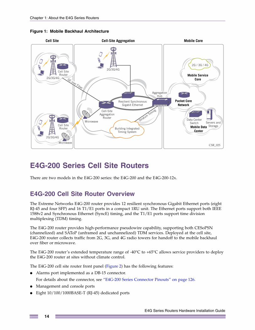
OverviewThe Extreme Networks E4G router family consists of the E4G-200 series cell site routers (E4G-200 and E4G-200-12x), and the E4G-400 cell site aggregation router. These routers provide high-bandwidth capacity, highly accurate and flexible timing, and Operations Administration and Maintenance (OAM) capabilities that support service level agreement (SLA) metrics. They support time-division multiplexing pseudowire end-to-end emulation (TDM PWE3). PWE allows the simultaneous support of multiple generations of services (2G, 3G and 4G) over the same Ethernet backhaul network without having to remove legacy T1/E1 equipment and incur associated costs.
The E4G-200 Series Cell Site Routers collect traffic from cell site towers for handoff to the mobile backhaul network. The E4G-200 series routers connect to the E4G-400 Cell Site Aggregation Router, which aggregates T1, E1. and Ethernet traffic for handoff to the mobile core (see Figure 1).
Installation Guide
13
Chapter 1: About the E4G Series Routers
Figure 1: Mobile Backhaul Architecture
E4G-200 Series Cell Site RoutersThere are two models in the E4G-200 series: the E4G-200 and the E4G-200-12x.
E4G-200 Cell Site Router OverviewThe Extreme Networks E4G-200 router provides 12 resilient synchronous Gigabit Ethernet ports (eight RJ-45 and four SFP) and 16 T1/E1 ports in a compact 1RU unit. The Ethernet ports support both IEEE 1588v2 and Synchronous Ethernet (SyncE) timing, and the T1/E1 ports support time division multiplexing (TDM) timing.
The E4G-200 router provides high-performance pseudowire capability, supporting both CESoPSN (channelized) and SAToP (unframed and unchannelized) TDM services. Deployed at the cell site, E4G-200 router collects traffic from 2G, 3G, and 4G radio towers for handoff to the mobile backhaul over fiber or microwave.
The E4G-200 router’s extended temperature range of -40°C to +65°C allows service providers to deploy the E4G-200 router at sites without climate control.
The E4G-200 cell site router front panel (Figure 2) has the following features:
● Alarms port implemented as a DB-15 connector.
For details about the connector, see “E4G-200 Series Connector Pinouts” on page 126.
● Management and console ports
● Eight 10/100/1000BASE-T (RJ-45) dedicated ports
CSR_025
Data CenterSwitch Servers and
StorageMobile DataCenter
Mobile Core
Cell SiteRouter
Cell SiteRouter
Cell-SiteAggregation
Router
Cell-Site AggregationCell Site
AggregationHub
Building IntegratedTiming System
Stratum Tim
ing
GE over Fiber
Resilient SynchronousGigabit Ethernet
2G / 3G / 4G
2G/3G/4G
2G/3G/4G
Microwave
Microwave
2G/3G/4GMobile Service
Core
Packet CoreNetwork
E4G Series Routers Hardware Installation Guide
14
E4G-200 Series Cell Site Routers
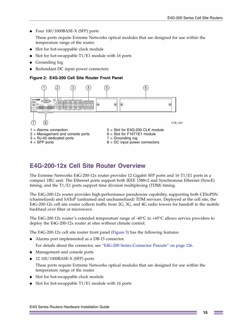
● Four 100/1000BASE-X (SFP) ports
These ports require Extreme Networks optical modules that are designed for use within the temperature range of the router.
● Slot for hot-swappable clock module
● Slot for hot-swappable T1/E1 module with 16 ports
● Grounding lug
● Redundant DC input power connectors
Figure 2: E4G-200 Cell Site Router Front Panel
E4G-200-12x Cell Site Router OverviewThe Extreme Networks E4G-200-12x router provides 12 Gigabit SFP ports and 16 T1/E1 ports in a compact 1RU unit. The Ethernet ports support both IEEE 1588v2 and Synchronous Ethernet (SyncE) timing, and the T1/E1 ports support time division multiplexing (TDM) timing.
The E4G-200-12x router provides high-performance pseudowire capability, supporting both CESoPSN (channelized) and SAToP (unframed and unchannelized) TDM services. Deployed at the cell site, the E4G-200-12x cell site router collects traffic from 2G, 3G, and 4G radio towers for handoff to the mobile backhaul over fiber or microwave.
The E4G-200-12x router’s extended temperature range of -40°C to +65°C allows service providers to deploy the E4G-200-12x router at sites without climate control.
The E4G-200-12x cell site router front panel (Figure 3) has the following features:
● Alarms port implemented as a DB-15 connector.
For details about the connector, see “E4G-200 Series Connector Pinouts” on page 126.
● Management and console ports
● 12 100/1000BASE-X (SFP) ports
These ports require Extreme Networks optical modules that are designed for use within the temperature range of the router.
● Slot for hot-swappable clock module
● Slot for hot-swappable T1/E1 module with 16 ports
CSR_020
1
7 8
2 3 54 6
1 = Alarms connection2 = Management and console ports3 = RJ-45 dedicated ports4 = SFP ports
5 = Slot for E4G-200 CLK module6 = Slot for F16T1E1 module7 = Grounding lug8 = DC input power connectors
E4G Series Routers Hardware Installation Guide
15
Chapter 1: About the E4G Series Routers
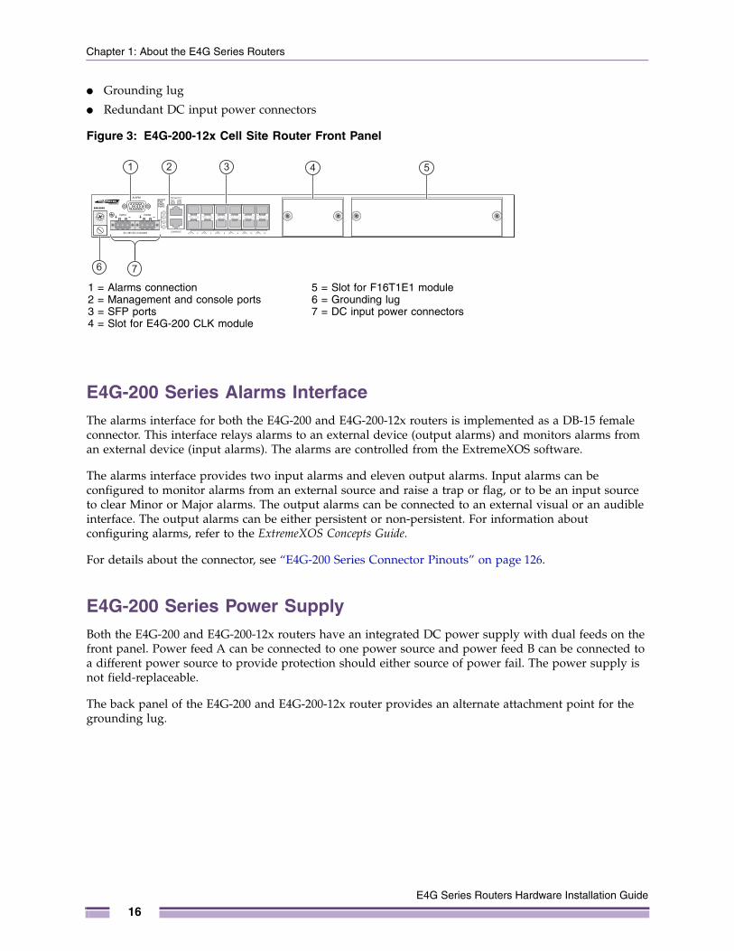
● Grounding lug
● Redundant DC input power connectors
Figure 3: E4G-200-12x Cell Site Router Front Panel
E4G-200 Series Alarms InterfaceThe alarms interface for both the E4G-200 and E4G-200-12x routers is implemented as a DB-15 female connector. This interface relays alarms to an external device (output alarms) and monitors alarms from an external device (input alarms). The alarms are controlled from the ExtremeXOS software.
The alarms interface provides two input alarms and eleven output alarms. Input alarms can be configured to monitor alarms from an external source and raise a trap or flag, or to be an input source to clear Minor or Major alarms. The output alarms can be connected to an external visual or an audible interface. The output alarms can be either persistent or non-persistent. For information about configuring alarms, refer to the ExtremeXOS Concepts Guide.
For details about the connector, see “E4G-200 Series Connector Pinouts” on page 126.
E4G-200 Series Power SupplyBoth the E4G-200 and E4G-200-12x routers have an integrated DC power supply with dual feeds on the front panel. Power feed A can be connected to one power source and power feed B can be connected to a different power source to provide protection should either source of power fail. The power supply is not field-replaceable.
The back panel of the E4G-200 and E4G-200-12x router provides an alternate attachment point for the grounding lug.
E4G-200X
1
7
2 3 54
6
1 = Alarms connection2 = Management and console ports3 = SFP ports4 = Slot for E4G-200 CLK module
5 = Slot for F16T1E1 module6 = Grounding lug7 = DC input power connectors
E4G Series Routers Hardware Installation Guide
16
E4G-200 Series Cell Site Routers
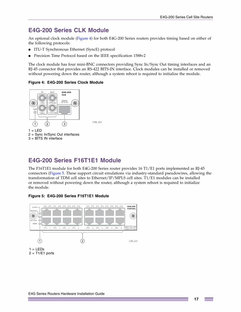
E4G-200 Series CLK ModuleAn optional clock module (Figure 4) for both E4G-200 Series routers provides timing based on either of the following protocols:
● ITU-T Synchronous Ethernet (SyncE) protocol
● Precision Time Protocol based on the IEEE specification 1588v2
The clock module has four mini-BNC connectors providing Sync In/Sync Out timing interfaces and an RJ-45 connector that provides an RS-422 BITS-IN interface. Clock modules can be installed or removed without powering down the router, although a system reboot is required to initialize the module.
Figure 4: E4G-200 Series Clock Module
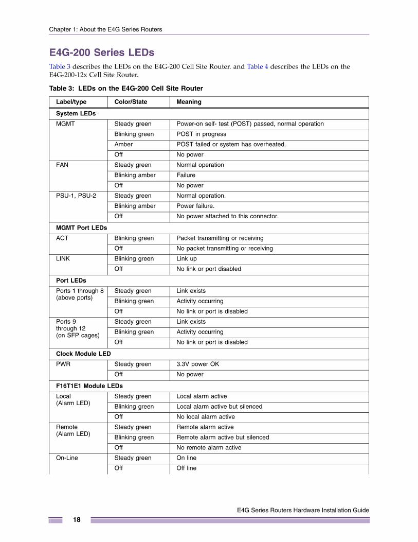
E4G-200 Series F16T1E1 ModuleThe F16T1E1 module for both E4G-200 Series router provides 16 T1/E1 ports implemented as RJ-45 connectors (Figure 5. These support circuit emulations via industry-standard pseudowires, allowing the transformation of TDM cell sites to Ethernet/IP/MPLS cell sites. T1/E1 modules can be installed or removed without powering down the router, although a system reboot is required to initialize the module.
Figure 5: E4G-200 Series F16T1E1 Module
CSR_0121 32
1 = LED2 = Sync In/Sync Out interfaces3 = BITS IN interface
CSR_0151 2
1 = LEDs2 = T1/E1 ports
E4G Series Routers Hardware Installation Guide
17
Chapter 1: About the E4G Series Routers
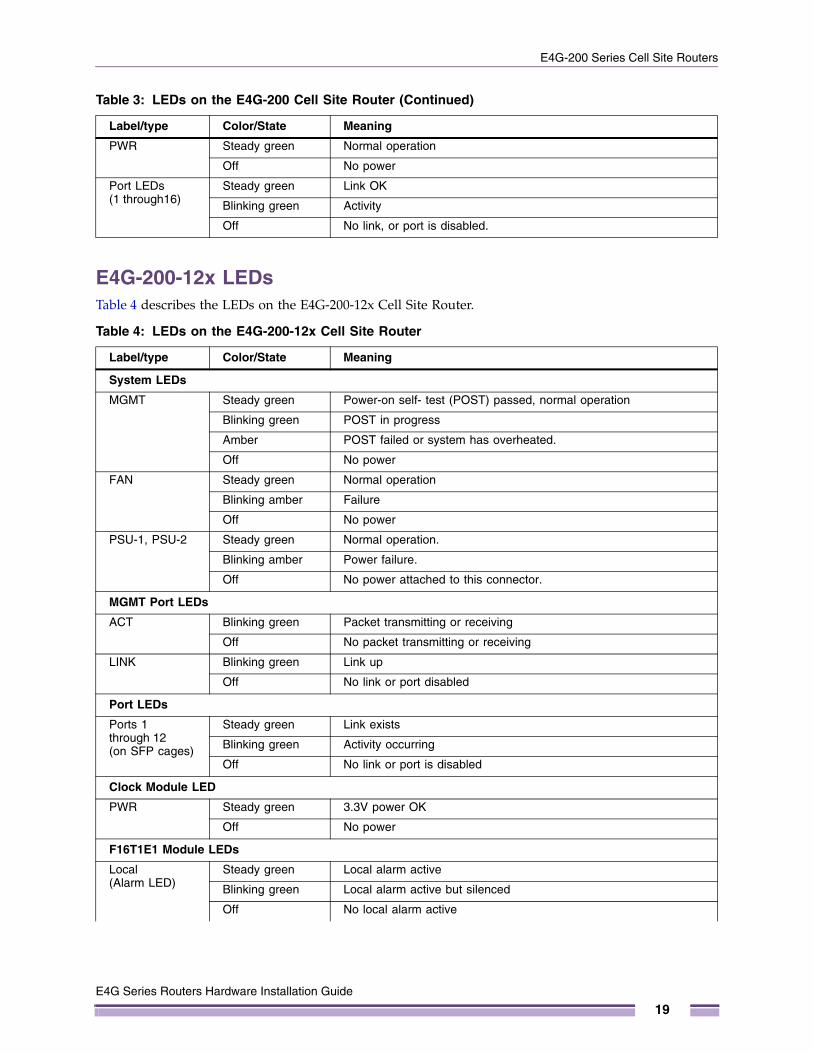
E4G-200 Series LEDsTable 3 describes the LEDs on the E4G-200 Cell Site Router. and Table 4 describes the LEDs on the E4G-200-12x Cell Site Router.
Table 3: LEDs on the E4G-200 Cell Site Router
Label/type Color/State Meaning
System LEDs
MGMT Steady green Power-on self- test (POST) passed, normal operation
Blinking green POST in progress
Amber POST failed or system has overheated.
Off No power
FAN Steady green Normal operation
Blinking amber Failure
Off No power
PSU-1, PSU-2 Steady green Normal operation.
Blinking amber Power failure.
Off No power attached to this connector.
MGMT Port LEDs
ACT Blinking green Packet transmitting or receiving
Off No packet transmitting or receiving
LINK Blinking green Link up
Off No link or port disabled
Port LEDs
Ports 1 through 8 (above ports)
Steady green Link exists
Blinking green Activity occurring
Off No link or port is disabled
Ports 9 through 12 (on SFP cages)
Steady green Link exists
Blinking green Activity occurring
Off No link or port is disabled
Clock Module LED
PWR Steady green 3.3V power OK
Off No power
F16T1E1 Module LEDs
Local(Alarm LED)
Steady green Local alarm active
Blinking green Local alarm active but silenced
Off No local alarm active
Remote(Alarm LED)
Steady green Remote alarm active
Blinking green Remote alarm active but silenced
Off No remote alarm active
On-Line Steady green On line
Off Off line
E4G Series Routers Hardware Installation Guide
18
E4G-200 Series Cell Site Routers
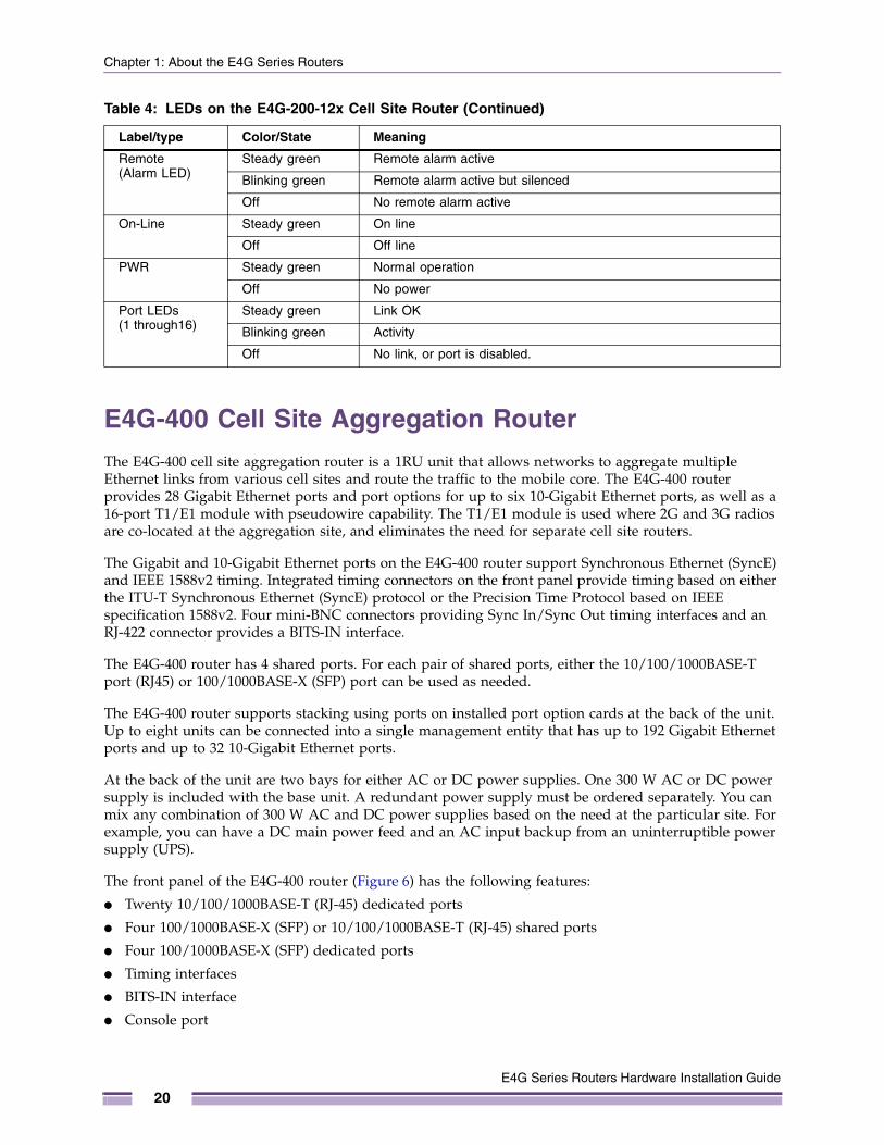
E4G-200-12x LEDsTable 4 describes the LEDs on the E4G-200-12x Cell Site Router.
PWR Steady green Normal operation
Off No power
Port LEDs (1 through16)
Steady green Link OK
Blinking green Activity
Off No link, or port is disabled.
Table 4: LEDs on the E4G-200-12x Cell Site Router
Label/type Color/State Meaning
System LEDs
MGMT Steady green Power-on self- test (POST) passed, normal operation
Blinking green POST in progress
Amber POST failed or system has overheated.
Off No power
FAN Steady green Normal operation
Blinking amber Failure
Off No power
PSU-1, PSU-2 Steady green Normal operation.
Blinking amber Power failure.
Off No power attached to this connector.
MGMT Port LEDs
ACT Blinking green Packet transmitting or receiving
Off No packet transmitting or receiving
LINK Blinking green Link up
Off No link or port disabled
Port LEDs
Ports 1 through 12 (on SFP cages)
Steady green Link exists
Blinking green Activity occurring
Off No link or port is disabled
Clock Module LED
PWR Steady green 3.3V power OK
Off No power
F16T1E1 Module LEDs
Local(Alarm LED)
Steady green Local alarm active
Blinking green Local alarm active but silenced
Off No local alarm active
Table 3: LEDs on the E4G-200 Cell Site Router (Continued)
Label/type Color/State Meaning
E4G Series Routers Hardware Installation Guide
19
Chapter 1: About the E4G Series Routers
E4G-400 Cell Site Aggregation RouterThe E4G-400 cell site aggregation router is a 1RU unit that allows networks to aggregate multiple Ethernet links from various cell sites and route the traffic to the mobile core. The E4G-400 router provides 28 Gigabit Ethernet ports and port options for up to six 10-Gigabit Ethernet ports, as well as a 16-port T1/E1 module with pseudowire capability. The T1/E1 module is used where 2G and 3G radios are co-located at the aggregation site, and eliminates the need for separate cell site routers.
The Gigabit and 10-Gigabit Ethernet ports on the E4G-400 router support Synchronous Ethernet (SyncE) and IEEE 1588v2 timing. Integrated timing connectors on the front panel provide timing based on either the ITU-T Synchronous Ethernet (SyncE) protocol or the Precision Time Protocol based on IEEE specification 1588v2. Four mini-BNC connectors providing Sync In/Sync Out timing interfaces and an RJ-422 connector provides a BITS-IN interface.
The E4G-400 router has 4 shared ports. For each pair of shared ports, either the 10/100/1000BASE-T port (RJ45) or 100/1000BASE-X (SFP) port can be used as needed.
The E4G-400 router supports stacking using ports on installed port option cards at the back of the unit. Up to eight units can be connected into a single management entity that has up to 192 Gigabit Ethernet ports and up to 32 10-Gigabit Ethernet ports.
At the back of the unit are two bays for either AC or DC power supplies. One 300 W AC or DC power supply is included with the base unit. A redundant power supply must be ordered separately. You can mix any combination of 300 W AC and DC power supplies based on the need at the particular site. For example, you can have a DC main power feed and an AC input backup from an uninterruptible power supply (UPS).
The front panel of the E4G-400 router (Figure 6) has the following features:
● Twenty 10/100/1000BASE-T (RJ-45) dedicated ports
● Four 100/1000BASE-X (SFP) or 10/100/1000BASE-T (RJ-45) shared ports
● Four 100/1000BASE-X (SFP) dedicated ports
● Timing interfaces
● BITS-IN interface
● Console port
Remote(Alarm LED)
Steady green Remote alarm active
Blinking green Remote alarm active but silenced
Off No remote alarm active
On-Line Steady green On line
Off Off line
PWR Steady green Normal operation
Off No power
Port LEDs (1 through16)
Steady green Link OK
Blinking green Activity
Off No link, or port is disabled.
Table 4: LEDs on the E4G-200-12x Cell Site Router (Continued)
Label/type Color/State Meaning
E4G Series Routers Hardware Installation Guide
20
E4G-400 Cell Site Aggregation Router
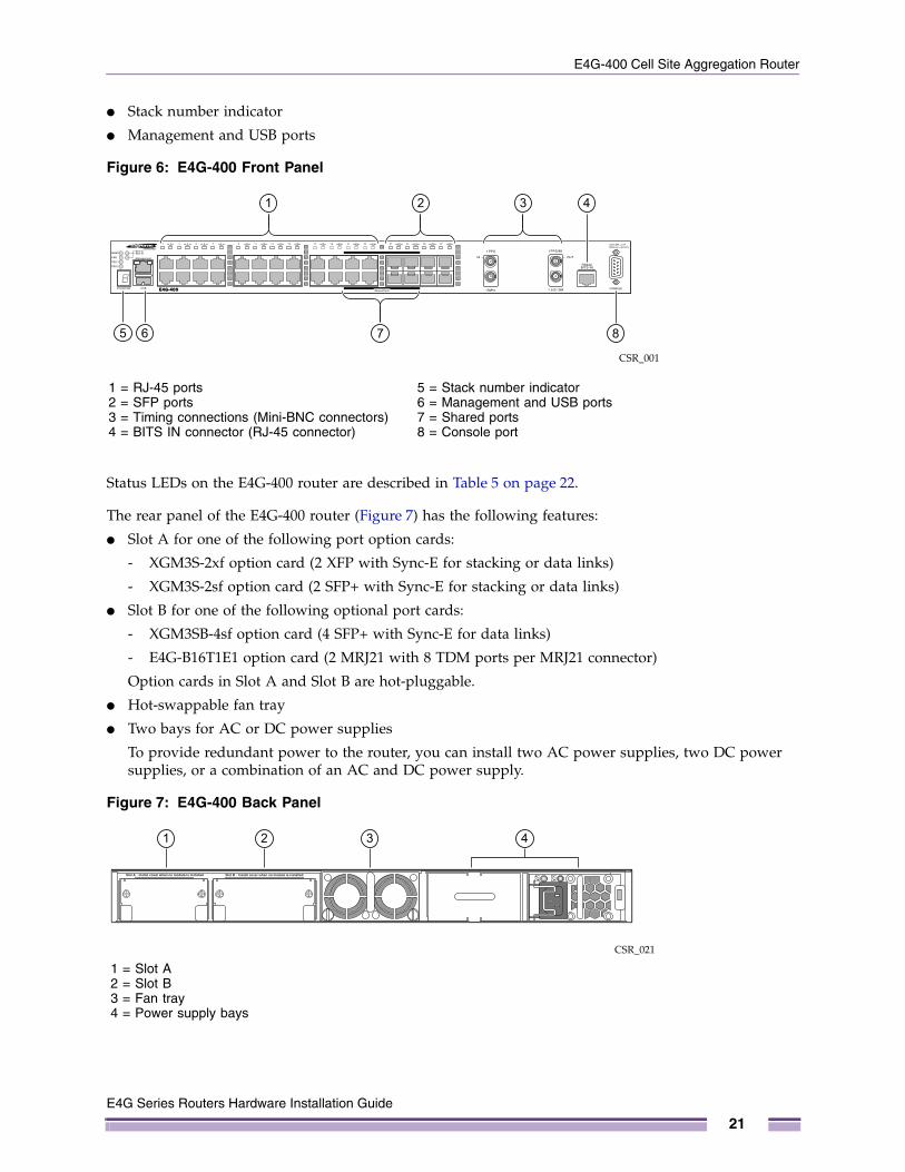
● Stack number indicator
● Management and USB ports
Figure 6: E4G-400 Front Panel
Status LEDs on the E4G-400 router are described in Table 5 on page 22.
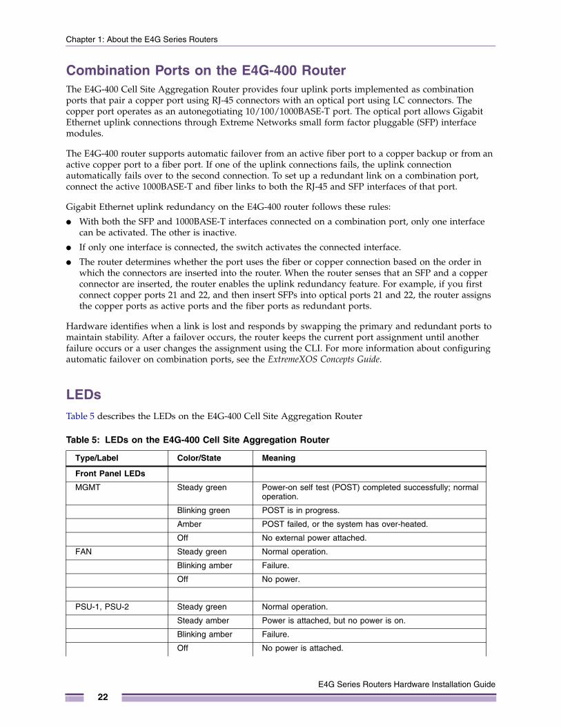
The rear panel of the E4G-400 router (Figure 7) has the following features:
● Slot A for one of the following port option cards:
- XGM3S-2xf option card (2 XFP with Sync-E for stacking or data links)
- XGM3S-2sf option card (2 SFP+ with Sync-E for stacking or data links)
● Slot B for one of the following optional port cards:
- XGM3SB-4sf option card (4 SFP+ with Sync-E for data links)
- E4G-B16T1E1 option card (2 MRJ21 with 8 TDM ports per MRJ21 connector)
Option cards in Slot A and Slot B are hot-pluggable.
● Hot-swappable fan tray
● Two bays for AC or DC power supplies
To provide redundant power to the router, you can install two AC power supplies, two DC power supplies, or a combination of an AC and DC power supply.
Figure 7: E4G-400 Back Panel
CSR_001
2 3 41
875 6
1 = RJ-45 ports2 = SFP ports3 = Timing connections (Mini-BNC connectors)4 = BITS IN connector (RJ-45 connector)
5 = Stack number indicator6 = Management and USB ports7 = Shared ports8 = Console port
CSR_021
1 2 3 4
1 = Slot A2 = Slot B3 = Fan tray4 = Power supply bays
E4G Series Routers Hardware Installation Guide
21
Chapter 1: About the E4G Series Routers
Combination Ports on the E4G-400 RouterThe E4G-400 Cell Site Aggregation Router provides four uplink ports implemented as combination ports that pair a copper port using RJ-45 connectors with an optical port using LC connectors. The copper port operates as an autonegotiating 10/100/1000BASE-T port. The optical port allows Gigabit Ethernet uplink connections through Extreme Networks small form factor pluggable (SFP) interface modules.
The E4G-400 router supports automatic failover from an active fiber port to a copper backup or from an active copper port to a fiber port. If one of the uplink connections fails, the uplink connection automatically fails over to the second connection. To set up a redundant link on a combination port, connect the active 1000BASE-T and fiber links to both the RJ-45 and SFP interfaces of that port.
Gigabit Ethernet uplink redundancy on the E4G-400 router follows these rules:
● With both the SFP and 1000BASE-T interfaces connected on a combination port, only one interface can be activated. The other is inactive.
● If only one interface is connected, the switch activates the connected interface.
● The router determines whether the port uses the fiber or copper connection based on the order in which the connectors are inserted into the router. When the router senses that an SFP and a copper connector are inserted, the router enables the uplink redundancy feature. For example, if you first connect copper ports 21 and 22, and then insert SFPs into optical ports 21 and 22, the router assigns the copper ports as active ports and the fiber ports as redundant ports.
Hardware identifies when a link is lost and responds by swapping the primary and redundant ports to maintain stability. After a failover occurs, the router keeps the current port assignment until another failure occurs or a user changes the assignment using the CLI. For more information about configuring automatic failover on combination ports, see the ExtremeXOS Concepts Guide.
LEDsTable 5 describes the LEDs on the E4G-400 Cell Site Aggregation Router
Table 5: LEDs on the E4G-400 Cell Site Aggregation Router
Type/Label Color/State Meaning
Front Panel LEDs
MGMT Steady green Power-on self test (POST) completed successfully; normal operation.
Blinking green POST is in progress.
Amber POST failed, or the system has over-heated.
Off No external power attached.
FAN Steady green Normal operation.
Blinking amber Failure.
Off No power.
PSU-1, PSU-2 Steady green Normal operation.
Steady amber Power is attached, but no power is on.
Blinking amber Failure.
Off No power is attached.
E4G Series Routers Hardware Installation Guide
22
E4G-400 Cell Site Aggregation Router
Slot-A, Slot-B Steady green Port option card is installed in the indicated slot at the back of the router.
Off No port option card is installed in the indicated slot at the back of the router.
2-digit Stack Number Indicator
Left digit (1) Reserved for future use
Right digit (1 – 8)
Indicates the position of this router in a stacked configuration.
Upper half blinking This router is the stack master node.
Lower half blinking This router is the stack backup node.
Lit steadily This router is a standby node in the stack.
Ethernet Ports1 through 28
Steady green Link OK
Blinking green Activity
Off No link, or port is disabled.
Management Port Steady green Link OK
Blinking green Activity
Off No link, or port is disabled.
Back Panel
Port LED on installed XGM3S-2sf option card
Steady green Link OK
Blinking green Activity
Off No link, or port is disabled.
Port LED on installed XGM3S-2xf option card
Steady green Link OK
Blinking green Activity
Off No link, or port is disabled.
Port LED on installed XGM3SB-4xf option card (S1 through S4)
Steady green Link OK
Blinking green Activity
Off No link, or port is disabled.
Port LED on installed E4G-B16T1E1 module (1 through16)
Steady green Link OK
Blinking green Activity
Off No link, or port is disabled.
Table 5: LEDs on the E4G-400 Cell Site Aggregation Router (Continued)
Type/Label Color/State Meaning
E4G Series Routers Hardware Installation Guide
23
Chapter 1: About the E4G Series Routers
Power Supplies for the E4G-400The E4G-400 router is compatible with the following power supplies:
● 300W AC power supply (model number 10930A)
● 300W DC power supply (model number 10934A)
● 300W DC Power supply (model number 10933)
An E4G-400 router accommodates one or two 300 W power supplies. You can combine AC and DC power supplies in the same E4G-400 router. In a redundant power configuration, both power supplies are fully fault-tolerant and load-sharing. You can remove one power supply without interrupting router operation.
NOTE
An AC power input cord is not provided with a 300 W AC power supply. You can order an appropriate cord from Extreme Networks or from your local supplier. The power cord must meet the requirements listed in “Power Supplies for the E4G-400 Router” on page 123.
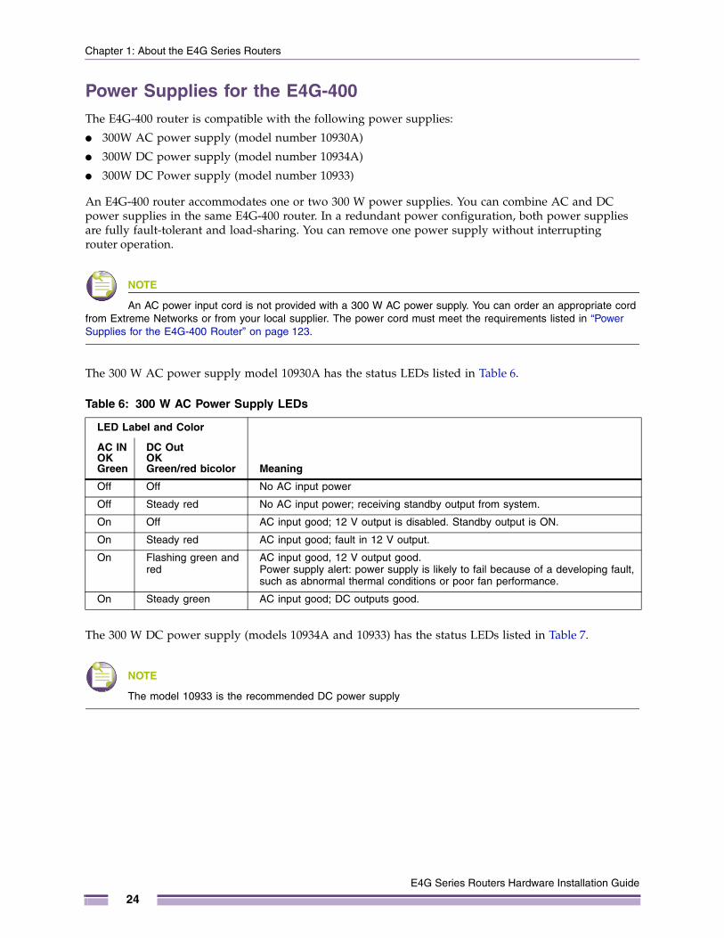
The 300 W AC power supply model 10930A has the status LEDs listed in Table 6.
The 300 W DC power supply (models 10934A and 10933) has the status LEDs listed in Table 7.
NOTE
The model 10933 is the recommended DC power supply
Table 6: 300 W AC Power Supply LEDs
LED Label and Color
Meaning
AC IN OKGreen
DC Out OK Green/red bicolor
Off Off No AC input power
Off Steady red No AC input power; receiving standby output from system.
On Off AC input good; 12 V output is disabled. Standby output is ON.
On Steady red AC input good; fault in 12 V output.
On Flashing green and red
AC input good, 12 V output good. Power supply alert: power supply is likely to fail because of a developing fault, such as abnormal thermal conditions or poor fan performance.
On Steady green AC input good; DC outputs good.
E4G Series Routers Hardware Installation Guide
24

E4G-400 Cell Site Aggregation Router
Optional Ports for the E4G-400 RouterThe rear panel of the E4G-400 router has two slots for installing optional port cards.
Slot A accommodates either of the following option cards:
● XGM3S-2sf option card
● XGM3S-2xf option card
Slot B accommodates either of the following options cards:
● XGM3SB-4sf option card
● E4G-B16T1E1 option card
XGM3S-2sf Option CardThe XGM3S-2sf option card (Figure 8) allows you to add one or two 10-Gigabit SFP+ optical ports to slot A on the rear panel of an E4G-400 router. These ports support synchronous Ethernet and can be used for stacking connections or data links. The XGM3S-2sf option card supports either SFP+ optical modules or an SFP+ direct-attach passive copper cable.
Figure 8: XGM3S-2sf Option Card
Table 7: 300 W DC Power Supply (models 10934A and 10933) LEDs
LED Label and Color
Meaning
DC In OKGreen
DC Out OK Green/red bicolor
Off Off No DC input power
Off Steady red No DC input power; receiving standby output from system.
On Off DC input is good; 12 V output is disabled. Standby output is ON.
On Steady red DC input is good; fault in 12 V output.
On Flashing green and red
DC input is good, 12 V output is good. Power supply alert: power supply is likely to fail because of a developing fault, such as abnormal thermal conditions or poor fan performance.
On Steady green DC input is good; DC outputs are good.
CSR_022
1
2
1 = SFP+ ports2 = LEDs
E4G Series Routers Hardware Installation Guide
25
Chapter 1: About the E4G Series Routers
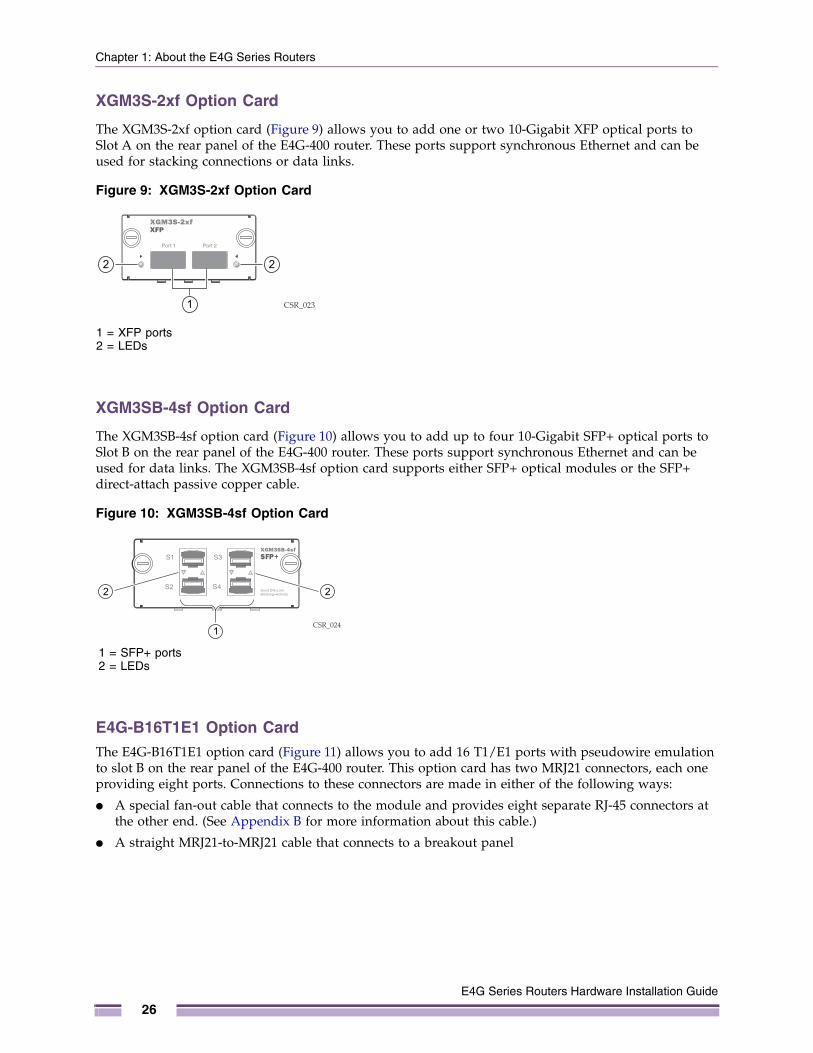
XGM3S-2xf Option Card
The XGM3S-2xf option card (Figure 9) allows you to add one or two 10-Gigabit XFP optical ports to Slot A on the rear panel of the E4G-400 router. These ports support synchronous Ethernet and can be used for stacking connections or data links.
Figure 9: XGM3S-2xf Option Card
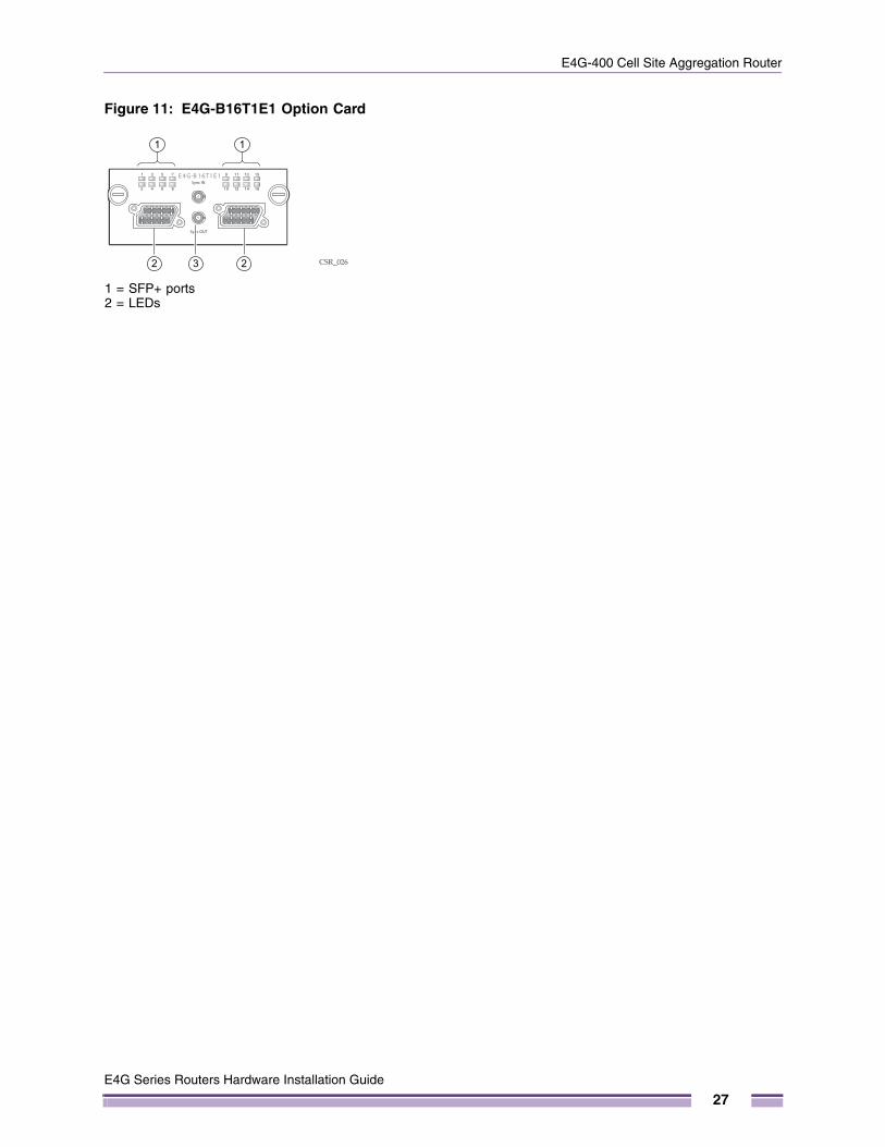
XGM3SB-4sf Option Card
The XGM3SB-4sf option card (Figure 10) allows you to add up to four 10-Gigabit SFP+ optical ports to Slot B on the rear panel of the E4G-400 router. These ports support synchronous Ethernet and can be used for data links. The XGM3SB-4sf option card supports either SFP+ optical modules or the SFP+ direct-attach passive copper cable.
Figure 10: XGM3SB-4sf Option Card
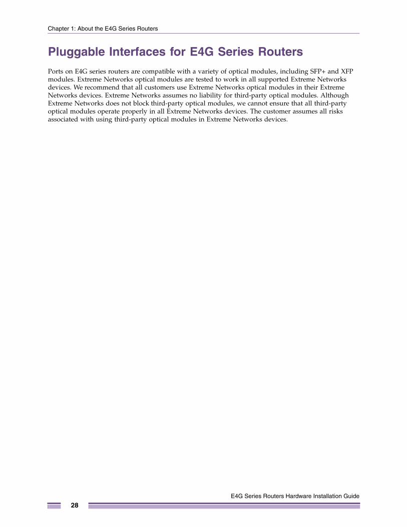
E4G-B16T1E1 Option CardThe E4G-B16T1E1 option card (Figure 11) allows you to add 16 T1/E1 ports with pseudowire emulation to slot B on the rear panel of the E4G-400 router. This option card has two MRJ21 connectors, each one providing eight ports. Connections to these connectors are made in either of the following ways:
● A special fan-out cable that connects to the module and provides eight separate RJ-45 connectors at the other end. (See Appendix B for more information about this cable.)
● A straight MRJ21-to-MRJ21 cable that connects to a breakout panel
CSR_0231
2 2
1 = XFP ports2 = LEDs
CSR_0241
22
1 = SFP+ ports2 = LEDs
E4G Series Routers Hardware Installation Guide
26
E4G-400 Cell Site Aggregation Router
Figure 11: E4G-B16T1E1 Option Card
CSR_026
1 1
32 2
1 = SFP+ ports2 = LEDs
E4G Series Routers Hardware Installation Guide
27
Chapter 1: About the E4G Series Routers
Pluggable Interfaces for E4G Series RoutersPorts on E4G series routers are compatible with a variety of optical modules, including SFP+ and XFP modules. Extreme Networks optical modules are tested to work in all supported Extreme Networks devices. We recommend that all customers use Extreme Networks optical modules in their Extreme Networks devices. Extreme Networks assumes no liability for third-party optical modules. Although Extreme Networks does not block third-party optical modules, we cannot ensure that all third-party optical modules operate properly in all Extreme Networks devices. The customer assumes all risks associated with using third-party optical modules in Extreme Networks devices.
E4G Series Routers Hardware Installation Guide
28

PART
Installing Hardware

2
E4G Series Routers Hardware
CHAPTER
Site Preparation
This chapter includes the following sections:
● Planning Your Site on page 32
● Meeting Site Requirements on page 32
● Evaluating and Meeting Cable Requirements on page 37
● Meeting Power Requirements on page 43
● Applicable Industry Standards on page 45
By carefully planning your site, you can maximize the performance of your existing network and ensure that it is ready to migrate to future networking technologies.
The information in this chapter is intended for the system administrator, network equipment technician, network manager, or facilities manager responsible for installing and managing the network hardware. The chapter assumes a working knowledge of local area network (LAN) operations, and a familiarity with communications protocols that are used on interconnected LANs.
Only qualified service personnel should install, maintain, or remove Extreme Networks equipment. Qualified service personnel have had appropriate technical training and experience that is necessary to be aware of the hazards to which they are exposed when performing a task and of measures to minimize the danger to themselves or other people.
NOTE
Before installing or removing any components of the system, or before carrying out any maintenance procedures, read the safety information in Appendix A of this guide.
Installation Guide
31
Chapter 2: Site Preparation
Planning Your SiteTo install your equipment successfully, you should plan the site carefully. The site planning process has three major parts:
● Meeting site requirements
The physical installation site must meet the following requirements for a safe and successful installation:
- Building and electrical code requirements
- Environmental, safety, and thermal requirements for the equipment you plan to install
- Equipment rack requirements
● Evaluating and meeting cable requirements
After examining your physical site and verifying that all environment requirements are met, evaluate and compare your existing cable plant with the requirements of the Extreme Networks equipment to determine if you need to install new cables.
● Meeting power requirements
To run your equipment safely, you must meet the specific power requirements for each router and external power supply unit installed in the system. For power specifications of the router and power supplies, see the specific router models listed in Appendix B.
Meeting Site RequirementsThis section describes requirements to consider when preparing your installation site, and includes the following topics:
● Operating Environment Requirements (next section)
● Rack and Cabinet Specifications and Recommendations on page 35
● Outdoor Installation Sites on page 37
Operating Environment RequirementsVerify that your site meets all environmental and safety requirements.
Virtually all areas of the United States are regulated by building codes and standards. During the early planning stages of installing or modifying your network, it is important that you develop a thorough understanding of the regulations that pertain to your location and industry.
Building and Electrical CodesBuilding and electrical codes vary depending on your location. Comply with all code specifications when planning your site and installing cable. This section lists resources for obtaining additional information.
For information about major building codes, consult the following organization:
International Code Council (ICC), 5203 Leesburg Pike; Falls Church, Virginia 22041 USA.
http://www.iccsafe.org
http://www.sbcci.org
E4G Series Routers Hardware Installation Guide
32
Meeting Site Requirements
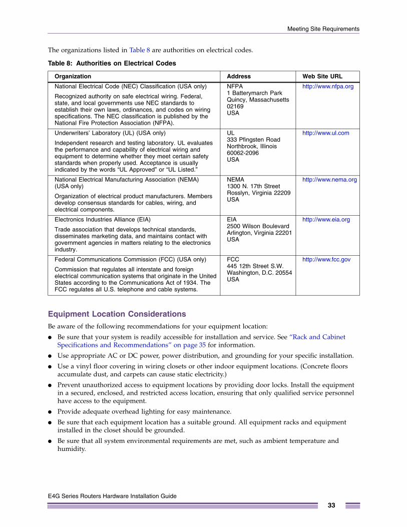
The organizations listed in Table 8 are authorities on electrical codes.
Equipment Location ConsiderationsBe aware of the following recommendations for your equipment location:
● Be sure that your system is readily accessible for installation and service. See “Rack and Cabinet Specifications and Recommendations” on page 35 for information.
● Use appropriate AC or DC power, power distribution, and grounding for your specific installation.
● Use a vinyl floor covering in wiring closets or other indoor equipment locations. (Concrete floors accumulate dust, and carpets can cause static electricity.)
● Prevent unauthorized access to equipment locations by providing door locks. Install the equipment in a secured, enclosed, and restricted access location, ensuring that only qualified service personnel have access to the equipment.
● Provide adequate overhead lighting for easy maintenance.
● Be sure that each equipment location has a suitable ground. All equipment racks and equipment installed in the closet should be grounded.
● Be sure that all system environmental requirements are met, such as ambient temperature and humidity.
Table 8: Authorities on Electrical Codes
Organization Address Web Site URL
National Electrical Code (NEC) Classification (USA only)
Recognized authority on safe electrical wiring. Federal, state, and local governments use NEC standards to establish their own laws, ordinances, and codes on wiring specifications. The NEC classification is published by the National Fire Protection Association (NFPA).
NFPA1 Batterymarch ParkQuincy, Massachusetts 02169 USA
http://www.nfpa.org
Underwriters’ Laboratory (UL) (USA only)
Independent research and testing laboratory. UL evaluates the performance and capability of electrical wiring and equipment to determine whether they meet certain safety standards when properly used. Acceptance is usually indicated by the words “UL Approved” or “UL Listed.”
UL333 Pfingsten RoadNorthbrook, Illinois 60062-2096 USA
http://www.ul.com
National Electrical Manufacturing Association (NEMA) (USA only)
Organization of electrical product manufacturers. Members develop consensus standards for cables, wiring, and electrical components.
NEMA1300 N. 17th StreetRosslyn, Virginia 22209USA
http://www.nema.org
Electronics Industries Alliance (EIA)
Trade association that develops technical standards, disseminates marketing data, and maintains contact with government agencies in matters relating to the electronics industry.
EIA2500 Wilson BoulevardArlington, Virginia 22201 USA
http://www.eia.org
Federal Communications Commission (FCC) (USA only)
Commission that regulates all interstate and foreign electrical communication systems that originate in the United States according to the Communications Act of 1934. The FCC regulates all U.S. telephone and cable systems.
FCC445 12th Street S.W.Washington, D.C. 20554 USA
http://www.fcc.gov
E4G Series Routers Hardware Installation Guide
33
Chapter 2: Site Preparation
NOTE
Extreme Networks recommends that you consult an electrical contractor for commercial building and wiring specifications.
TemperatureIt is important to keep installed equipment within the thermal operating specifications for optimum performance and safety.
Install the E4G-400 Cell Site Aggregation Router only in a temperature-controlled and humidity-controlled indoor area that is free of airborne materials that can conduct electricity. Too much humidity can cause a fire. Too little humidity can produce electrical shock and fire.
Follow these general thermal recommendations for the location of your equipment:
● Be sure that the ventilation in the installation site is adequate to maintain a temperature below 50° C (113° F) for the E4G-400 router or below 65° C (149° F) for the E4G-200 series router.
● Install a reliable air conditioning and ventilation system for indoor locations.
● Keep the ventilation in wiring closets running during non-business hours to prevent overheating of the equipment.
● Maintain an ambient operating temperature range of -10° to 50° C (14° to 122° F) for the E4G-400 router or a range of -40° to 65° C (-49° to 149° F) for the E4G-200 series router.
● Maintain a storage temperature of -40° to 70° C (-40° to 158° F).
NOTE
As with all electrical equipment, Extreme Networks product lifetimes degrade with increased temperature. If possible, temperatures should be kept at approximately 78° F (25° C) or lower.
HumidityTo maximize equipment life, keep operating humidity between 50% and 70% relative humidity (non-condensing) during typical operation. The equipment can operate between 10% and 95% relative humidity (non-condensing) for short intervals.
Spacing Requirements and AirflowBe sure that cables and other equipment do not block the air intake or outflow on an Extreme Networks router. It is best to have at least 3 inches (8 cm) of clear space in front of the air intake and outflow vents on the sides of the router; airflow moves from side to side. For proper airflow through an E4G series router, leave clear space on the left and right sides of the router.
Depending on other conditions in the equipment room, it may be possible to install the routers closer to each other; consult your Extreme Networks Customer Support representative for guidance.
E4G Series Routers Hardware Installation Guide
34
Meeting Site Requirements
Electrostatic Discharge Your system must be protected from static electricity or electrostatic discharge (ESD). Take the following measures to ensure optimum system performance:
● Remove materials that can cause electrostatic generation (such as synthetic resins) from the equipment location. Check the appropriateness of floor mats and flooring.
● Connect metal chassis, conduit, and other metals to ground using dedicated copper grounding lines.
● Use electrostatically safe equipment. If you are working with pluggable interface modules, wear an ESD-preventive device such as a wrist strap, and connect the metal end to a grounded equipment rack or other source of ground.
Rack and Cabinet Specifications and RecommendationsRacks and cabinets should conform to conventional standards. In the United States, use EIA Standard RS-310C: Racks, Panels, and Associated Equipment. In countries other than the United States, use IEC Standard 297. In addition, verify that your rack meets the basic mechanical, space, and earthquake requirements that are described in this section.
Mechanical Recommendations for the Rack
Use equipment racks that meet the following mechanical recommendations:
● Use an open style, 19-inch rack to facilitate easy maintenance and to provide proper ventilation.
● Use a rack made of steel or aluminum.
● The rack should use the universal mounting rail hole pattern that is identified in IEC Standard 297.
● The rack should have designated earth grounding connections (typically on the base).
● The rack must meet earthquake safety requirements equal to that of the installed system.
● The mounting holes should be flush with the rails to accommodate the installed system.
● The rack should support approximately 600 pounds (272 kilograms).
E4G Series Routers Hardware Installation Guide
35
Chapter 2: Site Preparation
Protective Grounding for the RackUse a rack grounding kit and a ground conductor that is carried back to earth or to another suitable building ground.
At a minimum, follow these guidelines to ground equipment racks to the earth ground:
● CAD weld appropriate wire terminals to building I-beams or earth ground rods.
● Use a minimum 14 AWG stranded copper wire for grounding an E4G-200 series router or a DC-powered E4G-400 router.
An AC-powered E4G-400 router does not need separate chassis grounding.
● Position the earth ground as close to the equipment rack as possible to maintain the shortest wiring distance possible.
● Use a ground impedance tester or micro-ohm meter to test the quality of earth ground connection at the chassis. This will ensure good grounding between the chassis, rack, and earth ground.
Extreme Networks equipment is designed with mounting brackets that provide solid metal-to-metal connection to the rack. Before you install an E4G series router in an equipment rack, clean the rack and mounting bracket surfaces and apply an antioxidant. When you secure an E4G series router to the rack, use thread-forming mounting screws that remove any paint or non-conductive coatings and establish metal-to-metal contact.
NOTE
Because building codes vary worldwide, Extreme Networks strongly recommends that you consult an electrical contractor to ensure proper equipment grounding for your specific installation.
Space Requirements for an E4G-400 RouterProvide enough space in front of and behind the router so that you can service it easily. Allow a minimum of 48 inches (122 cm) in front of the rack and 30 inches (76 cm) behind the rack. When using a relay (two-post) rack, provide a minimum of 24 inches (61 cm) of space behind the mounted equipment. Extra room on each side is optional.
Securing the RackThe rack should be attached to the floor with 3/8-inch (9.5 mm) lag screws or equivalent hardware. The floor under the rack should be level within 3/16-inch (5 mm). Use a floor-leveling cement compound if necessary or bolt the racks to the floor as shown in Figure 12.
E4G Series Routers Hardware Installation Guide
36
Evaluating and Meeting Cable Requirements
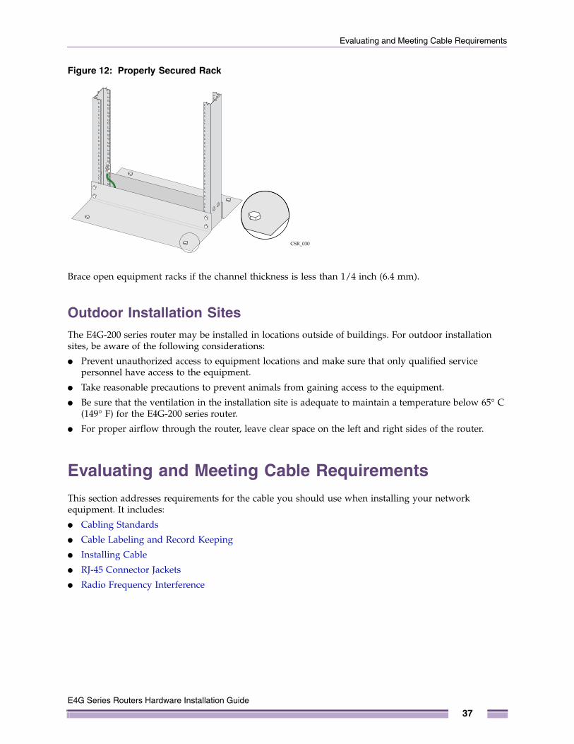
Figure 12: Properly Secured Rack
Brace open equipment racks if the channel thickness is less than 1/4 inch (6.4 mm).
Outdoor Installation SitesThe E4G-200 series router may be installed in locations outside of buildings. For outdoor installation sites, be aware of the following considerations:
● Prevent unauthorized access to equipment locations and make sure that only qualified service personnel have access to the equipment.
● Take reasonable precautions to prevent animals from gaining access to the equipment.
● Be sure that the ventilation in the installation site is adequate to maintain a temperature below 65° C (149° F) for the E4G-200 series router.
● For proper airflow through the router, leave clear space on the left and right sides of the router.
Evaluating and Meeting Cable RequirementsThis section addresses requirements for the cable you should use when installing your network equipment. It includes:
● Cabling Standards
● Cable Labeling and Record Keeping
● Installing Cable
● RJ-45 Connector Jackets
● Radio Frequency Interference
CSR_030
E4G Series Routers Hardware Installation Guide
37
Chapter 2: Site Preparation
Cabling StandardsExtreme Networks recommends using the Building Industry Consulting Service International (BICSI) Registered Communications Distribution Designer (RCDD), which is globally recognized as a standard in site planning and cabling. For information, go to:
http://www.bicsi.org
Cable Labeling and Record KeepingA reliable cable labeling system is essential when planning and installing a network. Maintaining accurate records helps you to:
● Relocate devices easily.
● Make changes quickly.
● Isolate faults in the distribution system.
● Locate the opposite end of any cable.
● Know the types of network devices that your cabling infrastructure can support.
Follow these guidelines when setting up a cable labeling system suitable for your installation:
● Identify cables by securely attaching labels to all cable ends.
● Assign a unique block of sequential numbers to the group of cables that run between each pair of equipment locations.
● Assign a unique identification number to each equipment rack.
● Identify all equipment locations by labeling the front panel of your Extreme Networks equipment and other hardware.
● Keep accurate and current cable identification records.
● Post records near each equipment rack. For each cable drop, include information about the cable source, destination, and jumper location.
Installing CableWhen you connect cable to your network equipment:
● Examine cable for cuts, bends, and nicks.
● Support cable using a cable manager that is mounted above connectors to avoid unnecessary weight on the cable bundles.
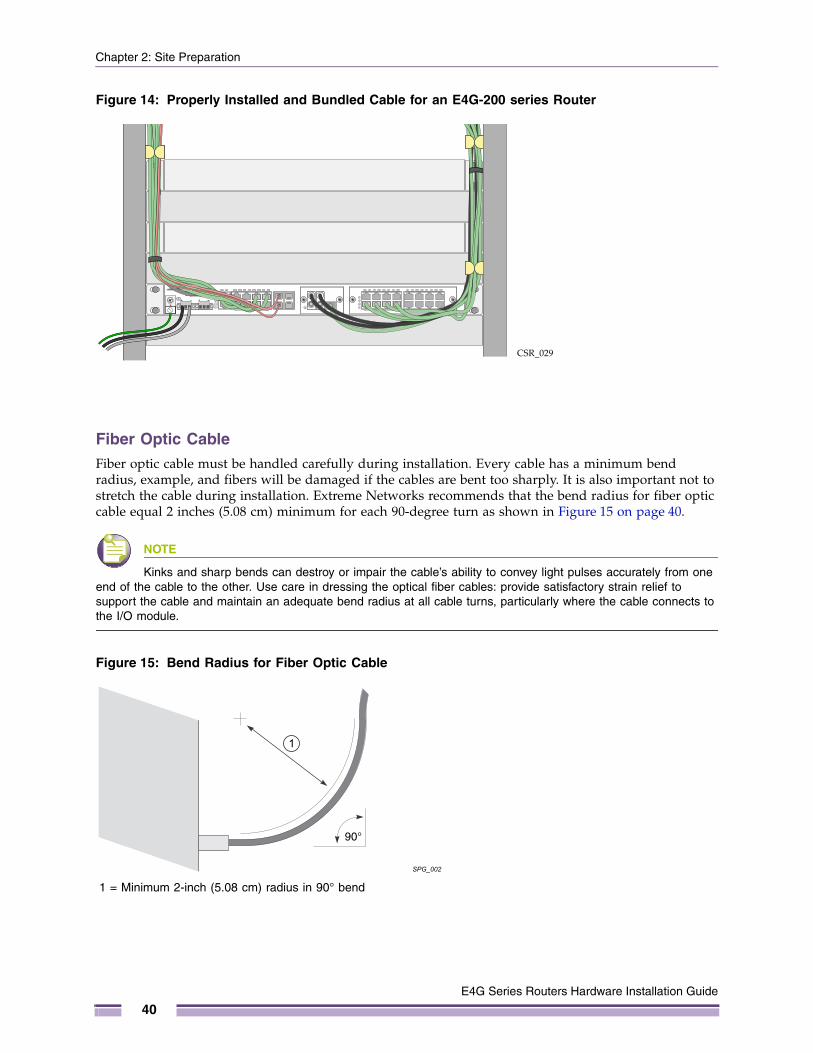
● Use cable managers to route cable bundles to the left and right of the network equipment to maximize accessibility to the connectors. (See Figure 13 and Figure 14.)
● Provide enough slack, approximately 2 to 3 inches (5.08 to 7.62 cm), to provide proper strain relief.
● Bundle cable using hook-and-loop straps to avoid injuring cables.
● If you build your own cable, be sure that connectors are properly crimped.
● When installing a patch panel using twisted pair wiring, untwist no more than 1 inch (2.54 cm) of the cable to avoid radio frequency (RF) interference.
● Discharge the RJ-45 Ethernet cable before plugging it into a port on the router.
E4G Series Routers Hardware Installation Guide
38
Evaluating and Meeting Cable Requirements
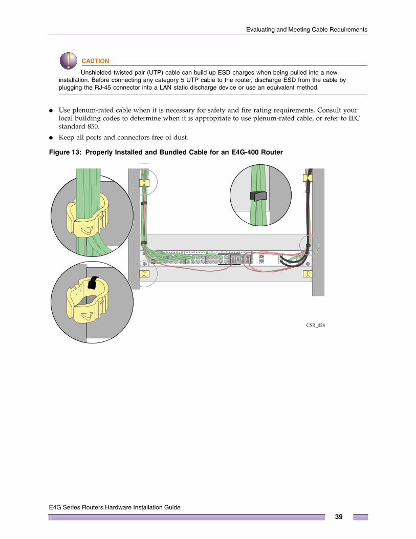
CAUTION
Unshielded twisted pair (UTP) cable can build up ESD charges when being pulled into a new installation. Before connecting any category 5 UTP cable to the router, discharge ESD from the cable by plugging the RJ-45 connector into a LAN static discharge device or use an equivalent method.
● Use plenum-rated cable when it is necessary for safety and fire rating requirements. Consult your local building codes to determine when it is appropriate to use plenum-rated cable, or refer to IEC standard 850.
● Keep all ports and connectors free of dust.
Figure 13: Properly Installed and Bundled Cable for an E4G-400 Router
CSR_028
E4G Series Routers Hardware Installation Guide
39
Chapter 2: Site Preparation
Figure 14: Properly Installed and Bundled Cable for an E4G-200 series Router
Fiber Optic CableFiber optic cable must be handled carefully during installation. Every cable has a minimum bend radius, example, and fibers will be damaged if the cables are bent too sharply. It is also important not to stretch the cable during installation. Extreme Networks recommends that the bend radius for fiber optic cable equal 2 inches (5.08 cm) minimum for each 90-degree turn as shown in Figure 15 on page 40.
NOTE
Kinks and sharp bends can destroy or impair the cable’s ability to convey light pulses accurately from one end of the cable to the other. Use care in dressing the optical fiber cables: provide satisfactory strain relief to support the cable and maintain an adequate bend radius at all cable turns, particularly where the cable connects to the I/O module.
Figure 15: Bend Radius for Fiber Optic Cable
CSR_029
SPG_002
90°
1
1 = Minimum 2-inch (5.08 cm) radius in 90° bend
E4G Series Routers Hardware Installation Guide
40
Evaluating and Meeting Cable Requirements
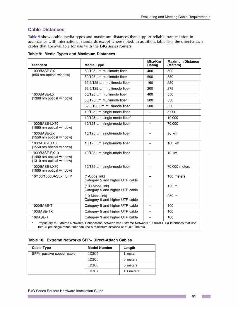
Cable DistancesTable 9 shows cable media types and maximum distances that support reliable transmission in accordance with international standards except where noted. In addition, table lists the direct-attach cables that are available for use with the E4G series routers.
Table 9: Media Types and Maximum Distances
Standard Media TypeMhz•Km Rating
Maximum Distance (Meters)
1000BASE-SX(850 nm optical window)
50/125 µm multimode fiber 400 500
50/125 µm multimode fiber 500 550
62.5/125 µm multimode fiber 160 220
62.5/125 µm multimode fiber 200 275
1000BASE-LX(1300 nm optical window)
50/125 µm multimode fiber 400 550
50/125 µm multimode fiber 500 550
62.5/125 µm multimode fiber 500 550
10/125 µm single-mode fiber – 5,000
10/125 µm single-mode fiber* – 10,000
1000BASE-LX70(1550 nm optical window)
10/125 µm single-mode fiber – 70,000
1000BASE-ZX(1550 nm optical window)
10/125 µm single-mode fiber – 80 km
100BASE-LX100(1550 nm optical window)
10/125 µm single-mode fiber – 100 km
1000BASE-BX10(1490 nm optical window)(1310 nm optical window)
10/125 µm single-mode fiber – 10 km
1000BASE-LX70(1550 nm optical window)
10/125 µm single-mode fiber – 70,000 meters
10/100/1000BASE-T SFP (1-Gbps link) Category 5 and higher UTP cable
– 100 meters
(100-Mbps link) Category 5 and higher UTP cable
– 150 m
(10-Mbps link) Category 5 and higher UTP cable
– 250 m
1000BASE-T Category 5 and higher UTP cable – 100
100BASE-TX Category 5 and higher UTP cable – 100
10BASE-T Category 3 and higher UTP cable – 100
* Proprietary to Extreme Networks. Connections between two Extreme Networks 1000BASE-LX interfaces that use 10/125 µm single-mode fiber can use a maximum distance of 10,000 meters.
Table 10: Extreme Networks SFP+ Direct-Attach Cables
Cable Type Model Number Length
SFP+ passive copper cable 10304 1 meter
10305 3 meters
10306 5 meters
10307 10 meters
E4G Series Routers Hardware Installation Guide
41
Chapter 2: Site Preparation
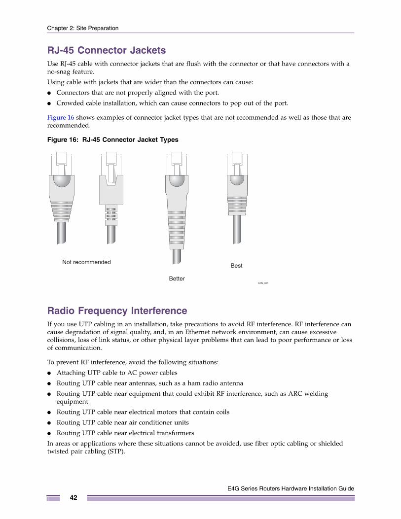
RJ-45 Connector JacketsUse RJ-45 cable with connector jackets that are flush with the connector or that have connectors with a no-snag feature.
Using cable with jackets that are wider than the connectors can cause:
● Connectors that are not properly aligned with the port.
● Crowded cable installation, which can cause connectors to pop out of the port.
Figure 16 shows examples of connector jacket types that are not recommended as well as those that are recommended.
Figure 16: RJ-45 Connector Jacket Types
Radio Frequency InterferenceIf you use UTP cabling in an installation, take precautions to avoid RF interference. RF interference can cause degradation of signal quality, and, in an Ethernet network environment, can cause excessive collisions, loss of link status, or other physical layer problems that can lead to poor performance or loss of communication.
To prevent RF interference, avoid the following situations:
● Attaching UTP cable to AC power cables
● Routing UTP cable near antennas, such as a ham radio antenna
● Routing UTP cable near equipment that could exhibit RF interference, such as ARC welding equipment
● Routing UTP cable near electrical motors that contain coils
● Routing UTP cable near air conditioner units
● Routing UTP cable near electrical transformers
In areas or applications where these situations cannot be avoided, use fiber optic cabling or shielded twisted pair cabling (STP).
0.1" = 1mm actual39.37% : 254%
SPG_001
Not recommended
Better
Best
E4G Series Routers Hardware Installation Guide
42

Meeting Power Requirements
Meeting Power RequirementsThis section describes power requirements and includes the following topics:
● Power Supply Requirements
● AC Power Cables
● Uninterruptible Power Supply Requirements
● DC Power Requirements
Power Supply RequirementsFollow these recommendations when you plan power supply connections for the E4G series routers:
● Place the equipment in an area that accommodates the power consumption and component heat dissipation specifications.
● Be sure that your power supply meets the site DC power or AC power requirements of the network equipment.
● When you connect power to installed equipment, do not make this connection through an extension cord or power strip.
● If your router includes more than one power supply, connect each power supply to a different, independent power source.
If a power source fails, it will affect only the router power supply to which it is connected. If all router power supplies are connected to a single power source, the entire router is vulnerable to a power source failure.
● In regions that are susceptible to electrical storms, Extreme networks recommends that you plug your system into a surge suppressor.
For power specifications for the E4G series routers, see Appendix B.
WARNING!
Extreme Networks routers do not have a switch for turning power to the unit on and off. For systems using an AC power supply, power to the router is disconnected by removing the wall plug from the electrical outlet.
For systems connected to DC power, turn off power to the chassis by de-energizing the circuit that feeds the power supply. This is usually accomplished by turning off a circuit breaker. Disconnecting the DC power cable from the DC power source must be done by a qualified, licensed electrician.
AC Power CablesAC power input cords are not included with Extreme Networks routers and power supplies. You can purchase AC power cords for use in the US and Canada from Extreme Networks or from your local supplier.
Power supply cords for use outside of the United States and Canada are typically provided separately by third-party distribution centers. Make sure that the power cord you use is certified for the country of end use and suitable for the device.
The power cord must meet the requirements listed in “Power Cord Requirements for AC Power Supplies” on page 125.
E4G Series Routers Hardware Installation Guide
43
Chapter 2: Site Preparation
Uninterruptible Power Supply RequirementsAn uninterruptible power supply (UPS) is a device that sits between a power supply (such as a wall outlet) and a device (such as a router) to prevent outages, sags, surges, and bad harmonics from adversely affecting the performance of the device.
A UPS traditionally can perform the following functions:
● Absorb relatively small power surges.
● Smooth out noisy power sources.
● Continue to provide power to equipment during line sags.
● Provide power for a period of time after a blackout has occurred.
In addition, some UPS devices or UPS-plus-software combinations provide the following functions:
● Automatically shut down equipment during long power outages.
● Monitor and log power supply status.
● Display the voltage (current draw) of the equipment.
● Restart equipment after a long power outage.
● Display the voltage currently on the line.
● Provide alarms on certain error conditions.
● Provide short-circuit protection.
Selecting a UPS To determine UPS requirements for your router, answer these questions:
● What are the amperage requirements?
● What is the longest potential time period that the UPS would be required to supply backup power?
● Where will the UPS be installed?
● What is the maximum transition time that the installation will allow? (See “UPS Transition Time” on page 45)
NOTE
Extreme Networks recommends that you use a UPS that provides online protection.
Calculating Volt-Amperage RequirementsTo determine the size of UPS that you need:
1 Locate the voltage and amperage requirements for each piece of equipment. These numbers are usually located on a sticker on the back or bottom of your equipment. Then multiply the numbers together to get Volt-Amperes (VA):
VA = Volts x Amperes
2 Add the VA from all the pieces of equipment together to find the total VA requirement.
To determine the minimum volt-amperage requirements for your UPS, Extreme Networks recommends that you add 30% to the total.
E4G Series Routers Hardware Installation Guide
44

Applicable Industry Standards
UPS Transition TimeTransition time is the time that is necessary for the UPS to transfer from utility power to full-load battery power. For Extreme Networks products, a transition time of less than 20 milliseconds is required for optimum performance.
DC Power RequirementsA DC-powered system should be installed in a DC-I battery return configuration. In a DC-I configuration, the battery return conductor should be connected directly to the central office power return bus, and not to the equipment frame or the grounding means of the equipment.
The E4G-200 series router can accept -48 or +24 volts for DC input.
Applicable Industry StandardsFor more information, see the following ANSI/TIA/EIA standards:
● ANSI/TIA/EIA-568-A—discusses the six subsystems of a structured cabling system.
● ANSI/TIA/EIA-569-A—discusses design considerations.
● ANSI/TIA/EIA-606—discusses cabling system administration.
● ANSI/TIA/EIA-607—discusses commercial building grounding and bonding requirements.
You can access these standards at:
http://www.ansi.org
or
http://www.tiaonline.org
E4G Series Routers Hardware Installation Guide
45

Chapter 2: Site Preparation
E4G Series Routers Hardware Installation Guide
46
3
E4G Series Routers Hardware
CHAPTER
Installing an E4G Series Router
This chapter provides instructions to install an E4G series router and includes the following sections:
● Pre-installation Requirements on page 47
● Installing the E4G-200 Series Cell Site Routers on page 48
● Installing the E4G-400 Cell Site Aggregation Router on page 56
● Installing Port Option Cards on page 67
● Initial Startup on page 71
● Initial Management Access on page 71
Pre-installation RequirementsRack mounting brackets and screws for attaching the brackets to the router are shipped with the router. You must provide the following additional tools and equipment to install the router in an equipment rack:
● Four rack mounting screws to match your equipment rack
● Screwdriver to fit the rack mounting screws
● ESD-preventive wrist strap for installing optional ports
For additional installation requirements, see the installation instructions for each router model.
Installation Guide
47
Chapter 3: Installing an E4G Series Router
Installing the E4G-200 Series Cell Site RoutersThe installation instructions for the E4G-200 and E4G-200-12x routers is the same. When you unpack the E4G-200 series cell site router (either E4G-200 or E4G-200-12x), verify that the package contains the following items:
● E4G-200 or E4G-200-12x router
● 2 rack-mounting brackets with 8 screws
● Ethernet console cable
● DB-9-to-RJ-45 adapter
● 2 pluggable DC terminal block connectors (Dinkle part number 2ESDVM-03P)
You need the following additional materials to ground the router and connect it to power:
● #14 AWG stranded copper cable for grounding the router and for connecting the router to the DC power source
Recommended insulation colors are:
- Green or green with yellow stripe for the ground connection
- Red and black for the power and return connections
● Connection hardware appropriate to the installation site:
- Hardware for connecting the ground wire to the site grounding point
- Hardware for connecting the power wires to the DC source
● Stripping tool
● Torque screwdriver and wrench or torque driver with attachments for tightening screws
- The ground lug requires a 1/4-inch screwdriver tip.
- The screws on the DC power connector require a 1/8-inch straight screwdriver tip.
Installing the E4G-200 series router includes the following tasks:
1 Install the router in a rack.
2 Ground the router.
3 Connect the router to power.
4 Install the clock module (optional) or T1/E1 module (optional).
5 Connect the alarms cable (optional).
6 Connect the console cable and perform initial configuration.
E4G Series Routers Hardware Installation Guide
48
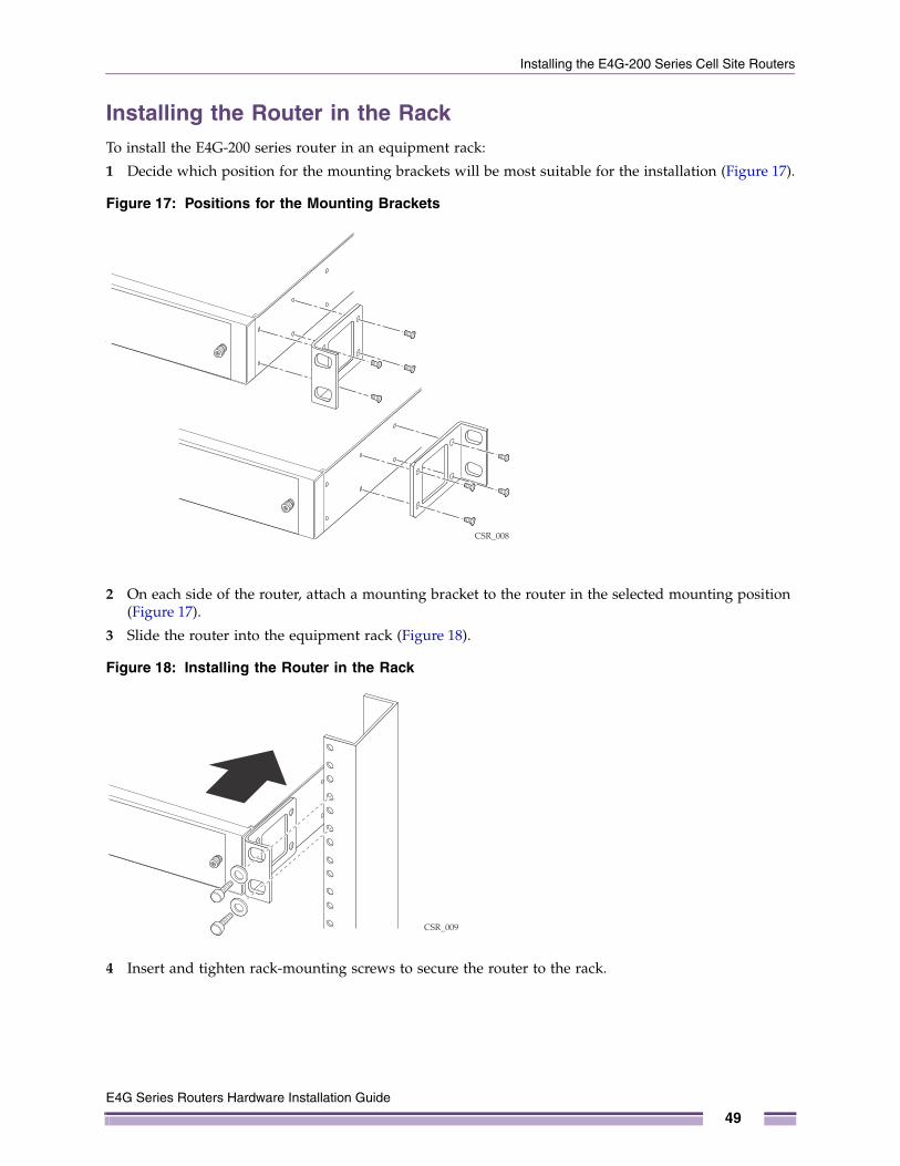
Installing the E4G-200 Series Cell Site Routers
Installing the Router in the RackTo install the E4G-200 series router in an equipment rack:
1 Decide which position for the mounting brackets will be most suitable for the installation (Figure 17).
Figure 17: Positions for the Mounting Brackets
2 On each side of the router, attach a mounting bracket to the router in the selected mounting position (Figure 17).
3 Slide the router into the equipment rack (Figure 18).
Figure 18: Installing the Router in the Rack
4 Insert and tighten rack-mounting screws to secure the router to the rack.
CSR_008
CSR_009
E4G Series Routers Hardware Installation Guide
49
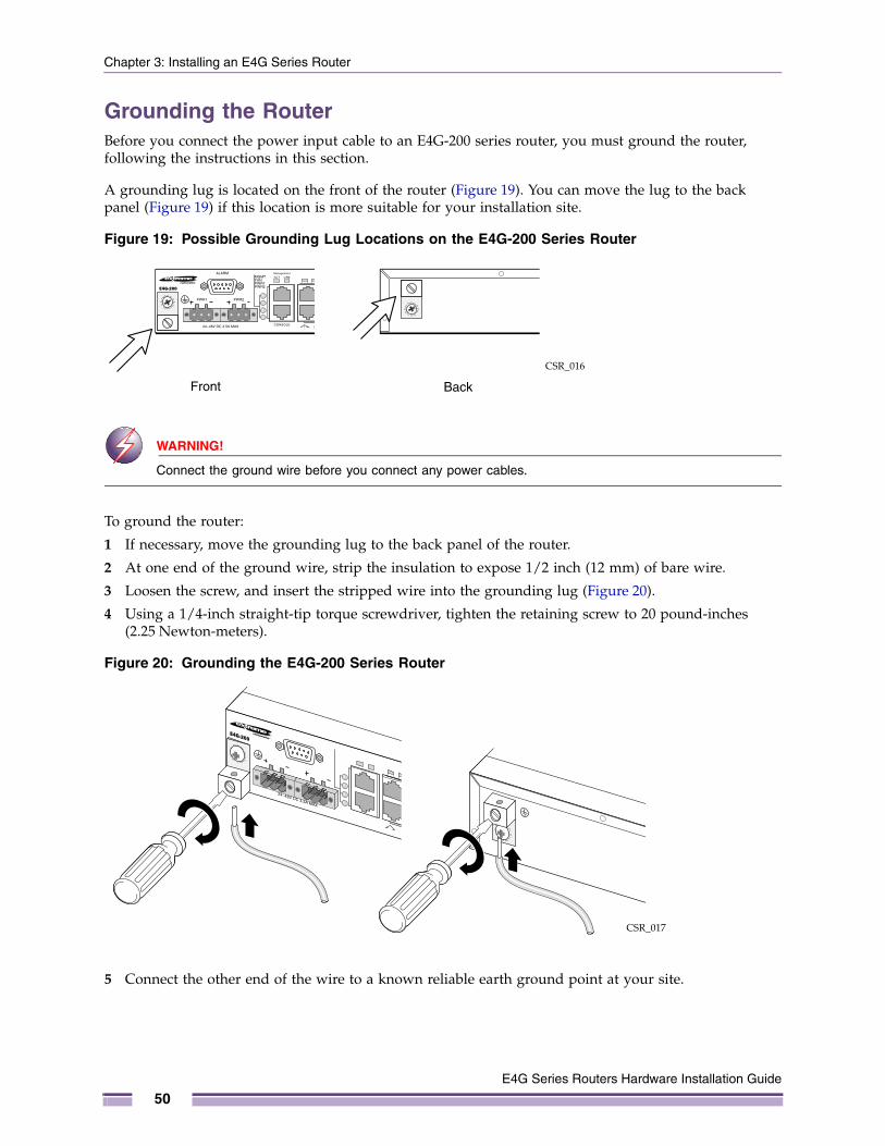
Chapter 3: Installing an E4G Series Router
Grounding the RouterBefore you connect the power input cable to an E4G-200 series router, you must ground the router, following the instructions in this section.
A grounding lug is located on the front of the router (Figure 19). You can move the lug to the back panel (Figure 19) if this location is more suitable for your installation site.
Figure 19: Possible Grounding Lug Locations on the E4G-200 Series Router
WARNING!
Connect the ground wire before you connect any power cables.
To ground the router:
1 If necessary, move the grounding lug to the back panel of the router.
2 At one end of the ground wire, strip the insulation to expose 1/2 inch (12 mm) of bare wire.
3 Loosen the screw, and insert the stripped wire into the grounding lug (Figure 20).
4 Using a 1/4-inch straight-tip torque screwdriver, tighten the retaining screw to 20 pound-inches (2.25 Newton-meters).
Figure 20: Grounding the E4G-200 Series Router
5 Connect the other end of the wire to a known reliable earth ground point at your site.
CSR_016
Front Back
CSR_017
E4G Series Routers Hardware Installation Guide
50
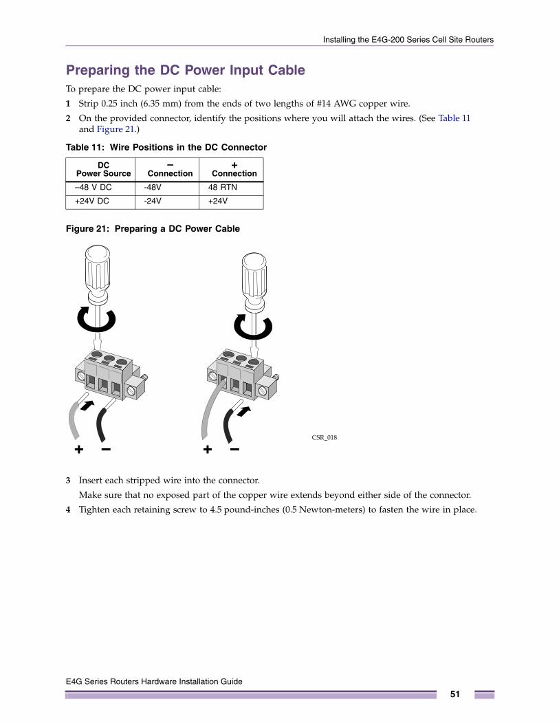
Installing the E4G-200 Series Cell Site Routers
Preparing the DC Power Input CableTo prepare the DC power input cable:
1 Strip 0.25 inch (6.35 mm) from the ends of two lengths of #14 AWG copper wire.
2 On the provided connector, identify the positions where you will attach the wires. (See Table 11 and Figure 21.)
Figure 21: Preparing a DC Power Cable
3 Insert each stripped wire into the connector.
Make sure that no exposed part of the copper wire extends beyond either side of the connector.
4 Tighten each retaining screw to 4.5 pound-inches (0.5 Newton-meters) to fasten the wire in place.
Table 11: Wire Positions in the DC Connector
DC Power Source
– Connection
+ Connection
–48 V DC -48V 48 RTN
+24V DC -24V +24V
CSR_018
E4G Series Routers Hardware Installation Guide
51
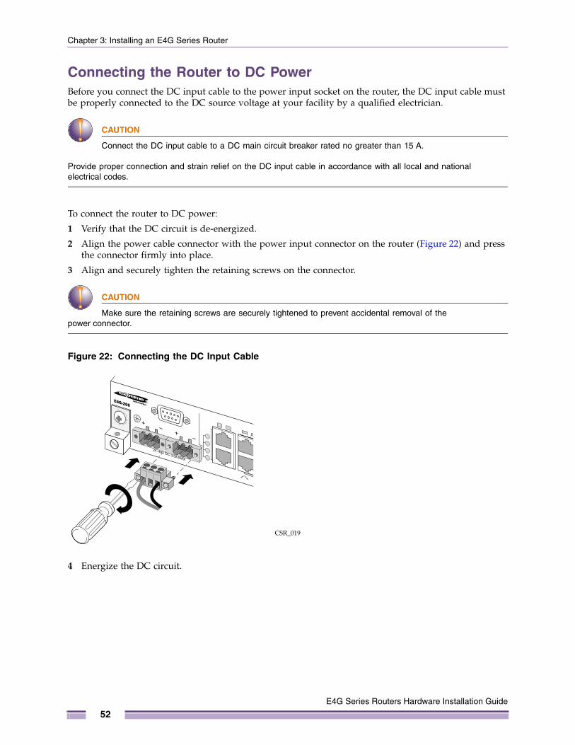
Chapter 3: Installing an E4G Series Router
Connecting the Router to DC PowerBefore you connect the DC input cable to the power input socket on the router, the DC input cable must be properly connected to the DC source voltage at your facility by a qualified electrician.
CAUTION
Connect the DC input cable to a DC main circuit breaker rated no greater than 15 A.
Provide proper connection and strain relief on the DC input cable in accordance with all local and national electrical codes.
To connect the router to DC power:
1 Verify that the DC circuit is de-energized.
2 Align the power cable connector with the power input connector on the router (Figure 22) and press the connector firmly into place.
3 Align and securely tighten the retaining screws on the connector.
CAUTION
Make sure the retaining screws are securely tightened to prevent accidental removal of the power connector.
Figure 22: Connecting the DC Input Cable
4 Energize the DC circuit.
CSR_019
E4G Series Routers Hardware Installation Guide
52

Installing the E4G-200 Series Cell Site Routers
Installing and Connecting a Clock ModuleYou can install or remove a clock module in the E4G-200 series router without powering down the router; however, you must reboot the router to initialize a newly installed clock module.
To install a clock module:
1 Attach an ESD-preventive wrist strap to your bare wrist and connect the metal end to an appropriate ground point on the rack.
2 On the front panel of the E4G-200 series router, remove the cover from the clock module slot (Figure 23).
Figure 23: Clock Module Slot Cover
3 Carefully slide the clock module all the way into the slot (Figure 24).
4 Align and securely tighten the captive retaining screws.
Figure 24: Installing a Clock Module
5 To initialize the clock module, reboot the router.
Save the cover for later re-use in case you must remove the clock module and do not have a replacement module. An unoccupied module slot must be covered to ensure satisfactory EMI levels and to maintain adequate airflow through the router.
CSR_010
CSR_011
E4G Series Routers Hardware Installation Guide
53
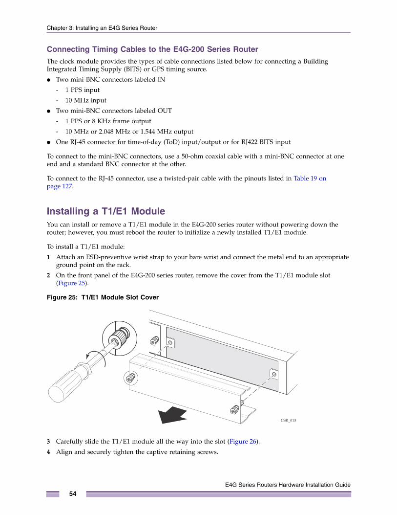
Chapter 3: Installing an E4G Series Router
Connecting Timing Cables to the E4G-200 Series RouterThe clock module provides the types of cable connections listed below for connecting a Building Integrated Timing Supply (BITS) or GPS timing source.
● Two mini-BNC connectors labeled IN
- 1 PPS input
- 10 MHz input
● Two mini-BNC connectors labeled OUT
- 1 PPS or 8 KHz frame output
- 10 MHz or 2.048 MHz or 1.544 MHz output
● One RJ-45 connector for time-of-day (ToD) input/output or for RJ422 BITS input
To connect to the mini-BNC connectors, use a 50-ohm coaxial cable with a mini-BNC connector at one end and a standard BNC connector at the other.
To connect to the RJ-45 connector, use a twisted-pair cable with the pinouts listed in Table 19 on page 127.
Installing a T1/E1 ModuleYou can install or remove a T1/E1 module in the E4G-200 series router without powering down the router; however, you must reboot the router to initialize a newly installed T1/E1 module.
To install a T1/E1 module:
1 Attach an ESD-preventive wrist strap to your bare wrist and connect the metal end to an appropriate ground point on the rack.
2 On the front panel of the E4G-200 series router, remove the cover from the T1/E1 module slot (Figure 25).
Figure 25: T1/E1 Module Slot Cover
3 Carefully slide the T1/E1 module all the way into the slot (Figure 26).
4 Align and securely tighten the captive retaining screws.
CSR_013
E4G Series Routers Hardware Installation Guide
54
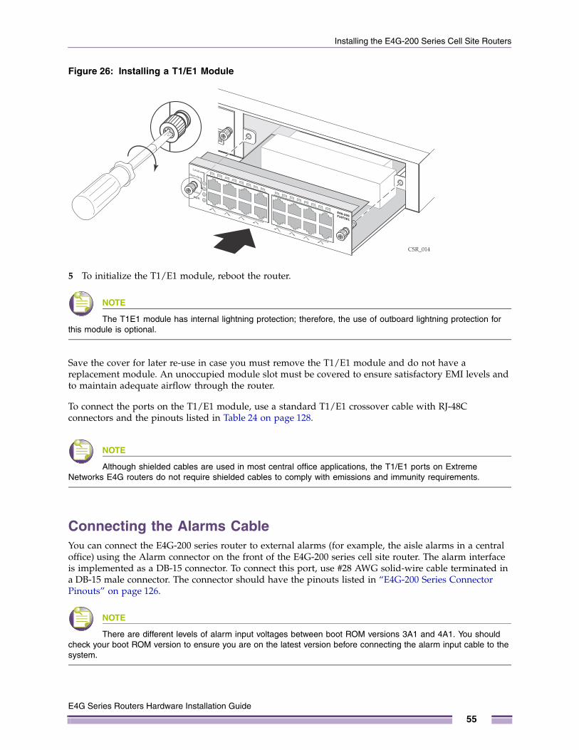
Installing the E4G-200 Series Cell Site Routers
Figure 26: Installing a T1/E1 Module
5 To initialize the T1/E1 module, reboot the router.
NOTE
The T1E1 module has internal lightning protection; therefore, the use of outboard lightning protection for this module is optional.
Save the cover for later re-use in case you must remove the T1/E1 module and do not have a replacement module. An unoccupied module slot must be covered to ensure satisfactory EMI levels and to maintain adequate airflow through the router.
To connect the ports on the T1/E1 module, use a standard T1/E1 crossover cable with RJ-48C connectors and the pinouts listed in Table 24 on page 128.
NOTE
Although shielded cables are used in most central office applications, the T1/E1 ports on Extreme Networks E4G routers do not require shielded cables to comply with emissions and immunity requirements.
Connecting the Alarms CableYou can connect the E4G-200 series router to external alarms (for example, the aisle alarms in a central office) using the Alarm connector on the front of the E4G-200 series cell site router. The alarm interface is implemented as a DB-15 connector. To connect this port, use #28 AWG solid-wire cable terminated in a DB-15 male connector. The connector should have the pinouts listed in “E4G-200 Series Connector Pinouts” on page 126.
NOTE
There are different levels of alarm input voltages between boot ROM versions 3A1 and 4A1. You should check your boot ROM version to ensure you are on the latest version before connecting the alarm input cable to the system.
CSR_014
E4G Series Routers Hardware Installation Guide
55
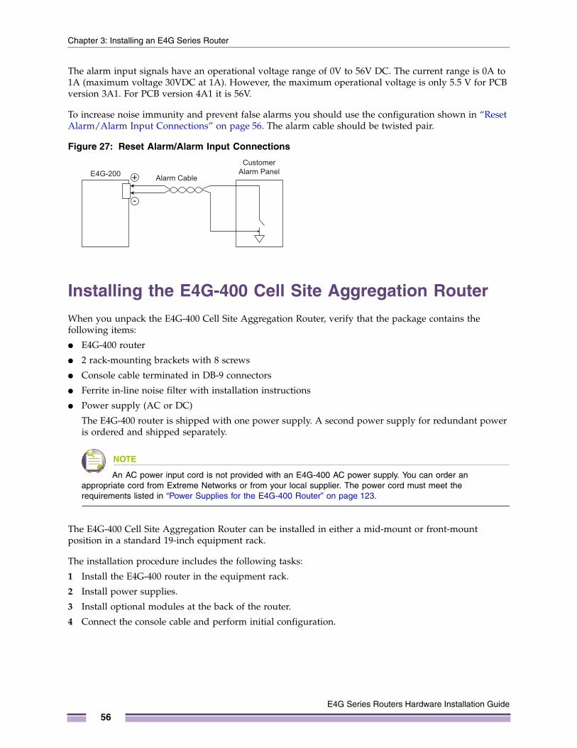
Chapter 3: Installing an E4G Series Router
The alarm input signals have an operational voltage range of 0V to 56V DC. The current range is 0A to 1A (maximum voltage 30VDC at 1A). However, the maximum operational voltage is only 5.5 V for PCB version 3A1. For PCB version 4A1 it is 56V.
To increase noise immunity and prevent false alarms you should use the configuration shown in “Reset Alarm/Alarm Input Connections” on page 56. The alarm cable should be twisted pair.
Figure 27: Reset Alarm/Alarm Input Connections
Installing the E4G-400 Cell Site Aggregation RouterWhen you unpack the E4G-400 Cell Site Aggregation Router, verify that the package contains the following items:
● E4G-400 router
● 2 rack-mounting brackets with 8 screws
● Console cable terminated in DB-9 connectors
● Ferrite in-line noise filter with installation instructions
● Power supply (AC or DC)
The E4G-400 router is shipped with one power supply. A second power supply for redundant power is ordered and shipped separately.
NOTE
An AC power input cord is not provided with an E4G-400 AC power supply. You can order an appropriate cord from Extreme Networks or from your local supplier. The power cord must meet the requirements listed in “Power Supplies for the E4G-400 Router” on page 123.
The E4G-400 Cell Site Aggregation Router can be installed in either a mid-mount or front-mount position in a standard 19-inch equipment rack.
The installation procedure includes the following tasks:
1 Install the E4G-400 router in the equipment rack.
2 Install power supplies.
3 Install optional modules at the back of the router.
4 Connect the console cable and perform initial configuration.
E4G-200Customer
Alarm Panel Alarm Cable
E4G Series Routers Hardware Installation Guide
56
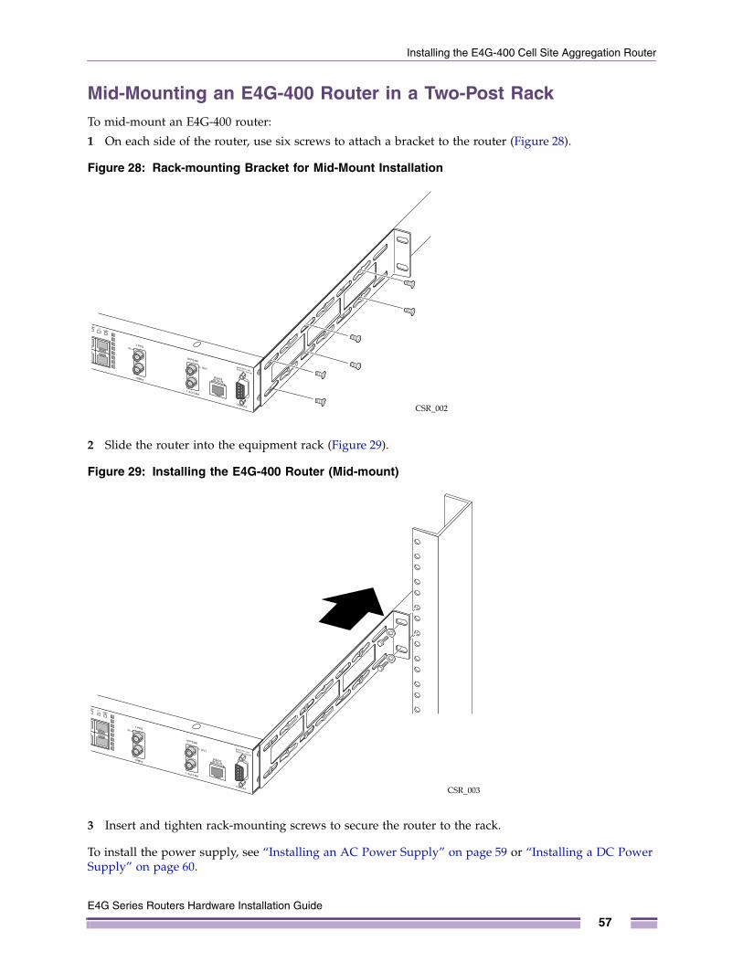
Installing the E4G-400 Cell Site Aggregation Router
Mid-Mounting an E4G-400 Router in a Two-Post RackTo mid-mount an E4G-400 router:
1 On each side of the router, use six screws to attach a bracket to the router (Figure 28).
Figure 28: Rack-mounting Bracket for Mid-Mount Installation
2 Slide the router into the equipment rack (Figure 29).
Figure 29: Installing the E4G-400 Router (Mid-mount)
3 Insert and tighten rack-mounting screws to secure the router to the rack.
To install the power supply, see “Installing an AC Power Supply” on page 59 or “Installing a DC Power Supply” on page 60.
CSR_002
CSR_003
E4G Series Routers Hardware Installation Guide
57
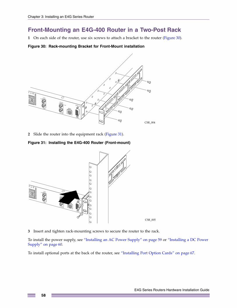
Chapter 3: Installing an E4G Series Router
Front-Mounting an E4G-400 Router in a Two-Post Rack1 On each side of the router, use six screws to attach a bracket to the router (Figure 30).
Figure 30: Rack-mounting Bracket for Front-Mount installation
2 Slide the router into the equipment rack (Figure 31).
Figure 31: Installing the E4G-400 Router (Front-mount)
3 Insert and tighten rack-mounting screws to secure the router to the rack.
To install the power supply, see “Installing an AC Power Supply” on page 59 or “Installing a DC Power Supply” on page 60.
To install optional ports at the back of the router, see “Installing Port Option Cards” on page 67.
CSR_004
CSR_005
E4G Series Routers Hardware Installation Guide
58
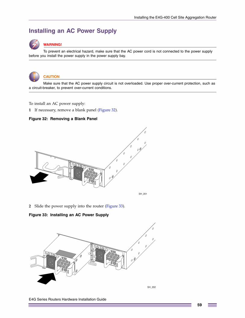
Installing the E4G-400 Cell Site Aggregation Router
Installing an AC Power Supply
WARNING!
To prevent an electrical hazard, make sure that the AC power cord is not connected to the power supply before you install the power supply in the power supply bay.
CAUTION
Make sure that the AC power supply circuit is not overloaded. Use proper over-current protection, such as a circuit-breaker, to prevent over-current conditions.
To install an AC power supply:
1 If necessary, remove a blank panel (Figure 32).
Figure 32: Removing a Blank Panel
2 Slide the power supply into the router (Figure 33).
Figure 33: Installing an AC Power Supply
SH_201
SH_202
E4G Series Routers Hardware Installation Guide
59
Chapter 3: Installing an E4G Series Router
3 Push the power supply in until the latch snaps into place.
NOTE
If power supplies are not installed in both power supply bays, be sure to install a cover over the unoccupied bay. The cover is required for maintaining proper system ventilation and EMI levels.
4 Connect the power cord to the power input connector and rotate the wire cord retainer over the power cord connector to hold the connector in place.
Installing a DC Power Supply
WARNING!
To prevent an electrical hazard, make sure that the DC power cord is not connected to the power supply before you install the power supply in the power supply bay.
CAUTION
Make sure that the DC power supply circuit is not overloaded. Use proper over-current protection, such as a circuit-breaker, to prevent over-current conditions. Do not use a breaker that is rated for higher than 30 Amps.
Preparing the DC CablesThe following terminals are provided with the power supply.
● Two spade terminals (Tyco part number 328281 or equivalent) for connecting the input power cables (provided)
● One ring terminal (Tyco part number 2-320561-4 or equivalent) and screw with captive lock washer (type 6-32 UNC) for connecting the ground wire (both provided)
You need a crimping tool to attach the terminals to the power and ground cables.
E4G Series Routers Hardware Installation Guide
60
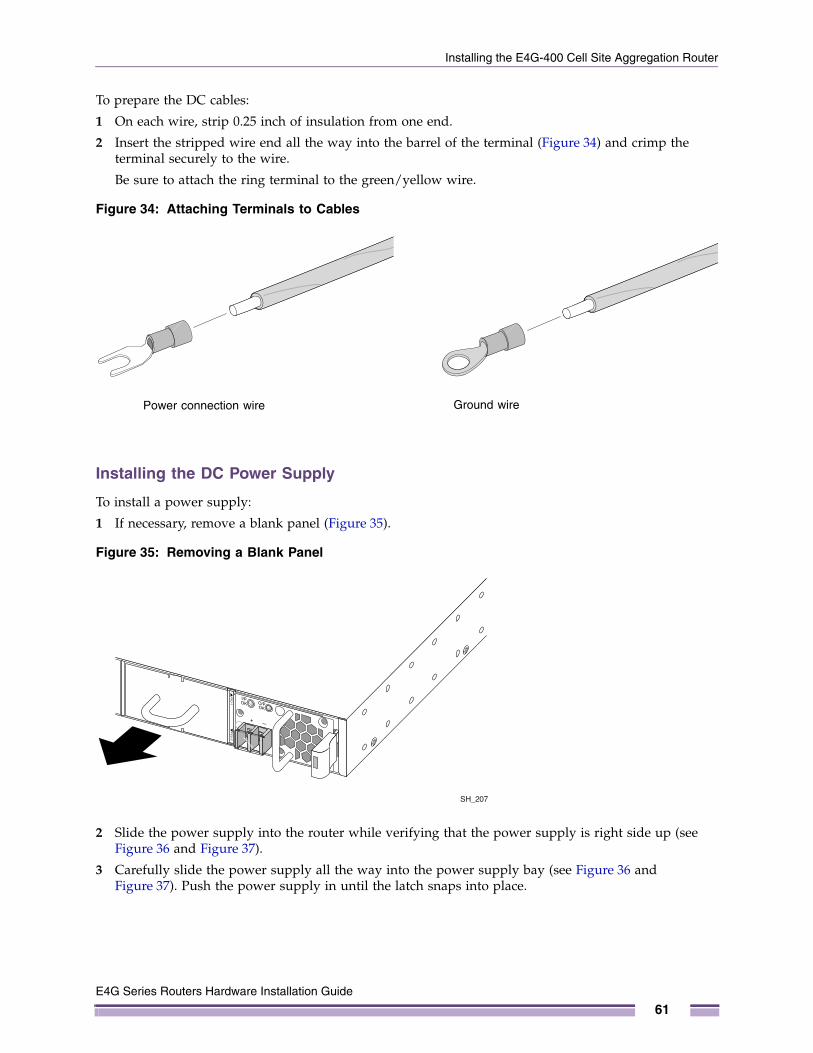
Installing the E4G-400 Cell Site Aggregation Router
To prepare the DC cables:
1 On each wire, strip 0.25 inch of insulation from one end.
2 Insert the stripped wire end all the way into the barrel of the terminal (Figure 34) and crimp the terminal securely to the wire.
Be sure to attach the ring terminal to the green/yellow wire.
Figure 34: Attaching Terminals to Cables
Installing the DC Power Supply
To install a power supply:
1 If necessary, remove a blank panel (Figure 35).
Figure 35: Removing a Blank Panel
2 Slide the power supply into the router while verifying that the power supply is right side up (see Figure 36 and Figure 37).
3 Carefully slide the power supply all the way into the power supply bay (see Figure 36 and Figure 37). Push the power supply in until the latch snaps into place.
SH_109
Power connection wire Ground wire
SH_207
E4G Series Routers Hardware Installation Guide
61
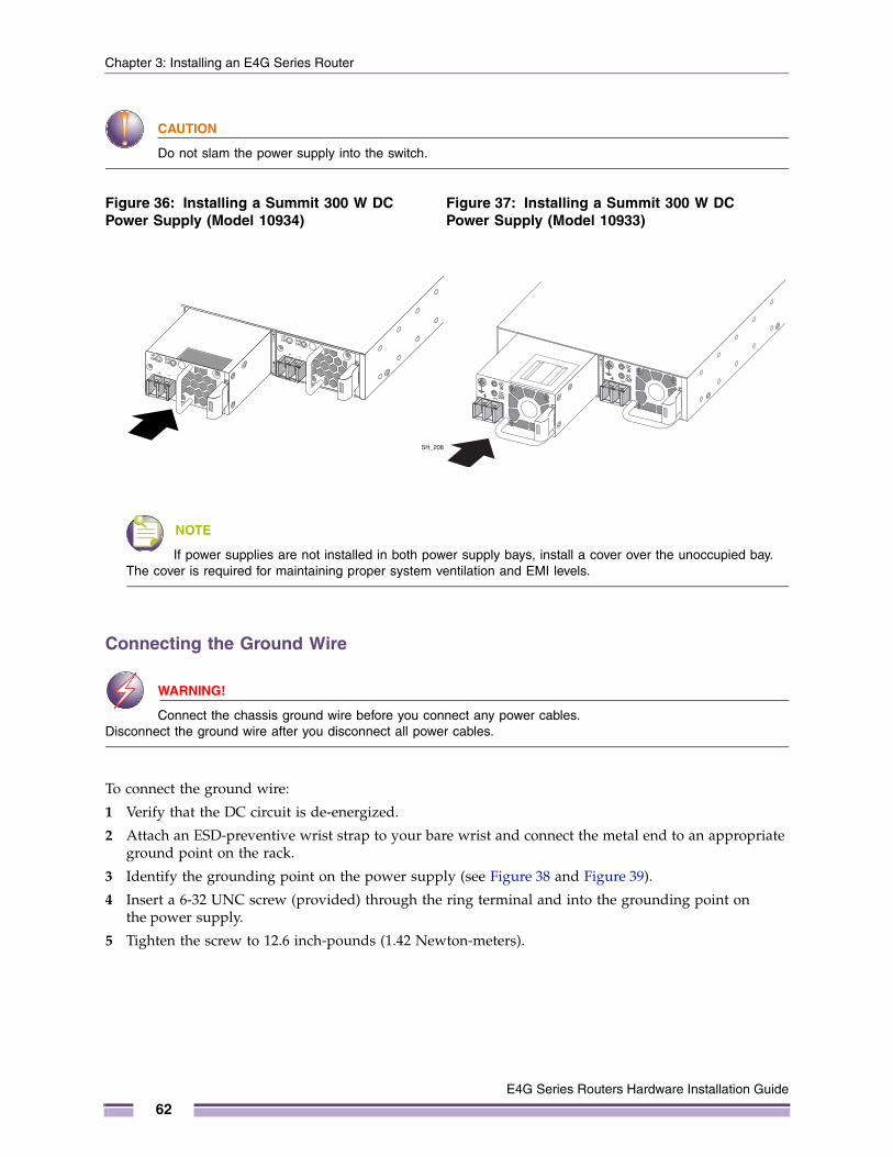
Chapter 3: Installing an E4G Series Router
CAUTION
Do not slam the power supply into the switch.
NOTE
If power supplies are not installed in both power supply bays, install a cover over the unoccupied bay. The cover is required for maintaining proper system ventilation and EMI levels.
Connecting the Ground Wire
WARNING!
Connect the chassis ground wire before you connect any power cables. Disconnect the ground wire after you disconnect all power cables.
To connect the ground wire:
1 Verify that the DC circuit is de-energized.
2 Attach an ESD-preventive wrist strap to your bare wrist and connect the metal end to an appropriate ground point on the rack.
3 Identify the grounding point on the power supply (see Figure 38 and Figure 39).
4 Insert a 6-32 UNC screw (provided) through the ring terminal and into the grounding point on the power supply.
5 Tighten the screw to 12.6 inch-pounds (1.42 Newton-meters).
Figure 36: Installing a Summit 300 W DC Power Supply (Model 10934)
Figure 37: Installing a Summit 300 W DC Power Supply (Model 10933)
SH_208
E4G Series Routers Hardware Installation Guide
62
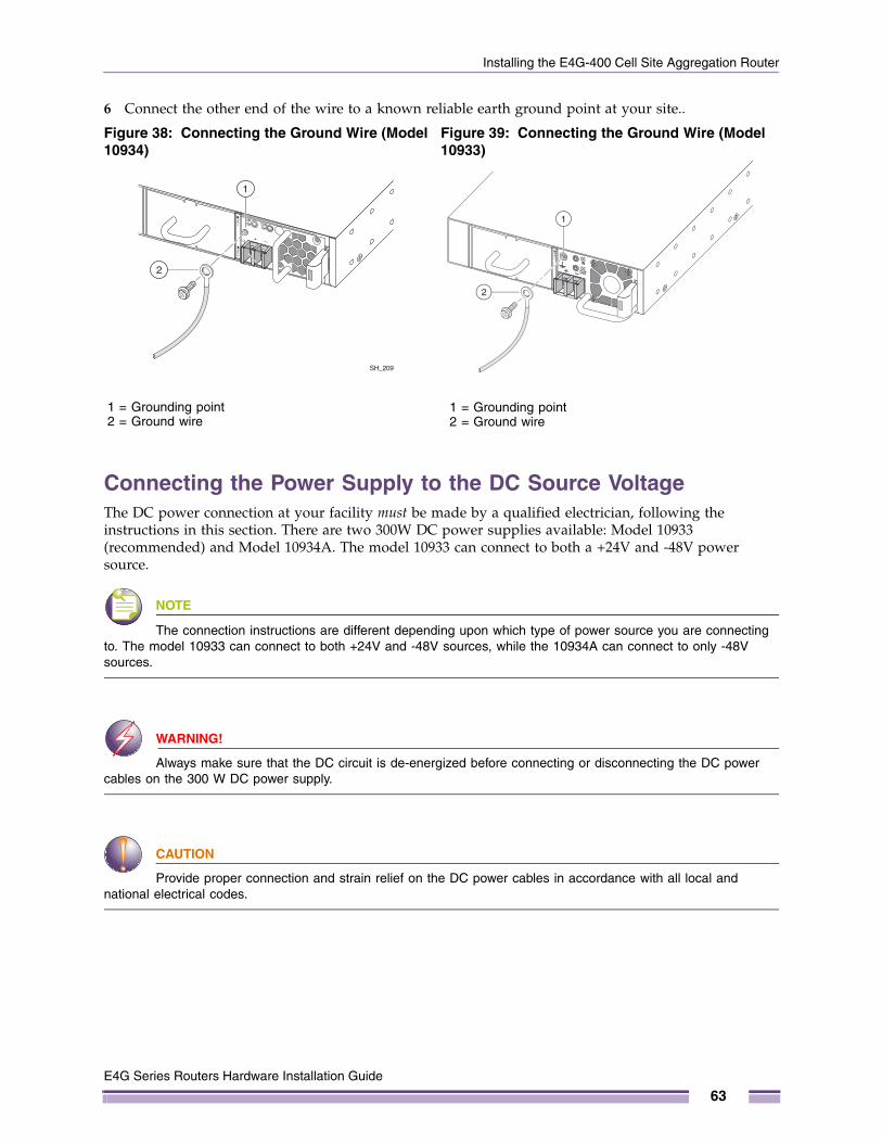
Installing the E4G-400 Cell Site Aggregation Router
6 Connect the other end of the wire to a known reliable earth ground point at your site..
Connecting the Power Supply to the DC Source VoltageThe DC power connection at your facility must be made by a qualified electrician, following the instructions in this section. There are two 300W DC power supplies available: Model 10933 (recommended) and Model 10934A. The model 10933 can connect to both a +24V and -48V power source.
NOTE
The connection instructions are different depending upon which type of power source you are connecting to. The model 10933 can connect to both +24V and -48V sources, while the 10934A can connect to only -48V sources.
WARNING!
Always make sure that the DC circuit is de-energized before connecting or disconnecting the DC power cables on the 300 W DC power supply.
CAUTION
Provide proper connection and strain relief on the DC power cables in accordance with all local and national electrical codes.
Figure 38: Connecting the Ground Wire (Model 10934)
Figure 39: Connecting the Ground Wire (Model 10933)
SH_209
1
2
1 = Grounding point2 = Ground wire
1
2
1 = Grounding point2 = Ground wire
E4G Series Routers Hardware Installation Guide
63

Chapter 3: Installing an E4G Series Router
Connecting the Model 10933 DC power supply to a +24V source
CAUTION
These instructions are for the Model 10933 DC power supply only. Do not connect a Model 10934A DC power supply to a +24V source.
To connect the DC power input cables on an model 10933 power supply to a +24V source:
1 Verify that the DC circuit is de-energized.
2 Attach an ESD-preventive wrist strap to your bare wrist and connect the metal end to an appropriate ground point on the rack.
3 Slide the cover off the terminal block (Figure 40).
4 Connect the DC power input cables as follows:
a On each terminal, loosen the screw enough to allow the spade terminal to slide underneath the captive square washer.
b Slide the spade terminal of the negative wire (–24 V) under the captive square washer on the negative terminal (labeled –24V).
c Slide the spade terminal of the positive wire (+24 V) under the captive square washer on the positive terminal (+24V).
Figure 40: Connecting the DC Power Cables (Part 1)
d Tighten both screws on the terminal block to 11 inch-pounds (1.25 Newton-meters) (Figure 41).
(+)
(–)
+24V-24V
SH_210A
E4G Series Routers Hardware Installation Guide
64
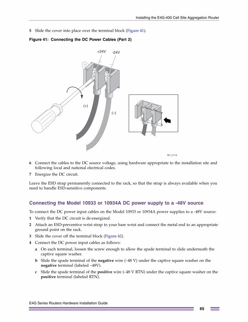
Installing the E4G-400 Cell Site Aggregation Router
5 Slide the cover into place over the terminal block (Figure 41).
Figure 41: Connecting the DC Power Cables (Part 2)
6 Connect the cables to the DC source voltage, using hardware appropriate to the installation site and following local and national electrical codes.
7 Energize the DC circuit.
Leave the ESD strap permanently connected to the rack, so that the strap is always available when you need to handle ESD-sensitive components.
Connecting the Model 10933 or 10934A DC power supply to a -48V source
To connect the DC power input cables on the Model 10933 or 10934A power supplies to a -48V source:
1 Verify that the DC circuit is de-energized.
2 Attach an ESD-preventive wrist strap to your bare wrist and connect the metal end to an appropriate ground point on the rack.
3 Slide the cover off the terminal block (Figure 42).
4 Connect the DC power input cables as follows:
a On each terminal, loosen the screw enough to allow the spade terminal to slide underneath the captive square washer.
b Slide the spade terminal of the negative wire (–48 V) under the captive square washer on the negative terminal (labeled –48V).
c Slide the spade terminal of the positive wire (–48 V RTN) under the captive square washer on the positive terminal (labeled RTN).
SH_211A
(+)
(–)
+24V -24V
E4G Series Routers Hardware Installation Guide
65
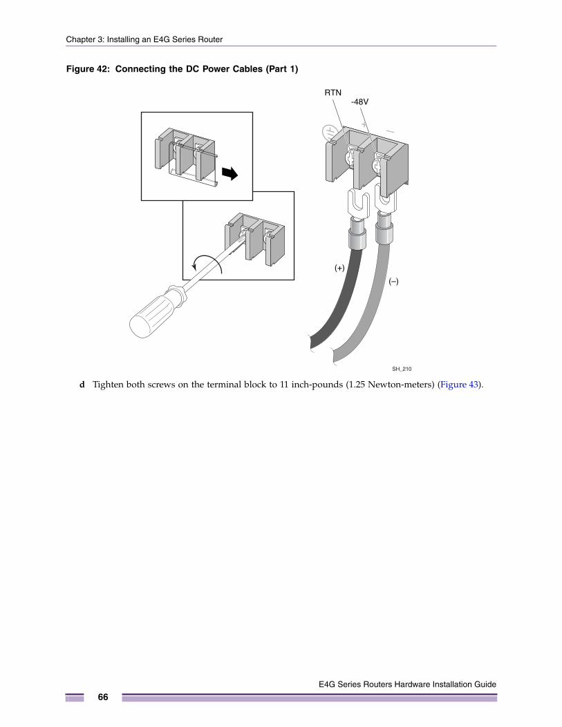
Chapter 3: Installing an E4G Series Router
Figure 42: Connecting the DC Power Cables (Part 1)
d Tighten both screws on the terminal block to 11 inch-pounds (1.25 Newton-meters) (Figure 43).
(+)
(–)
RTN-48V
SH_210
E4G Series Routers Hardware Installation Guide
66
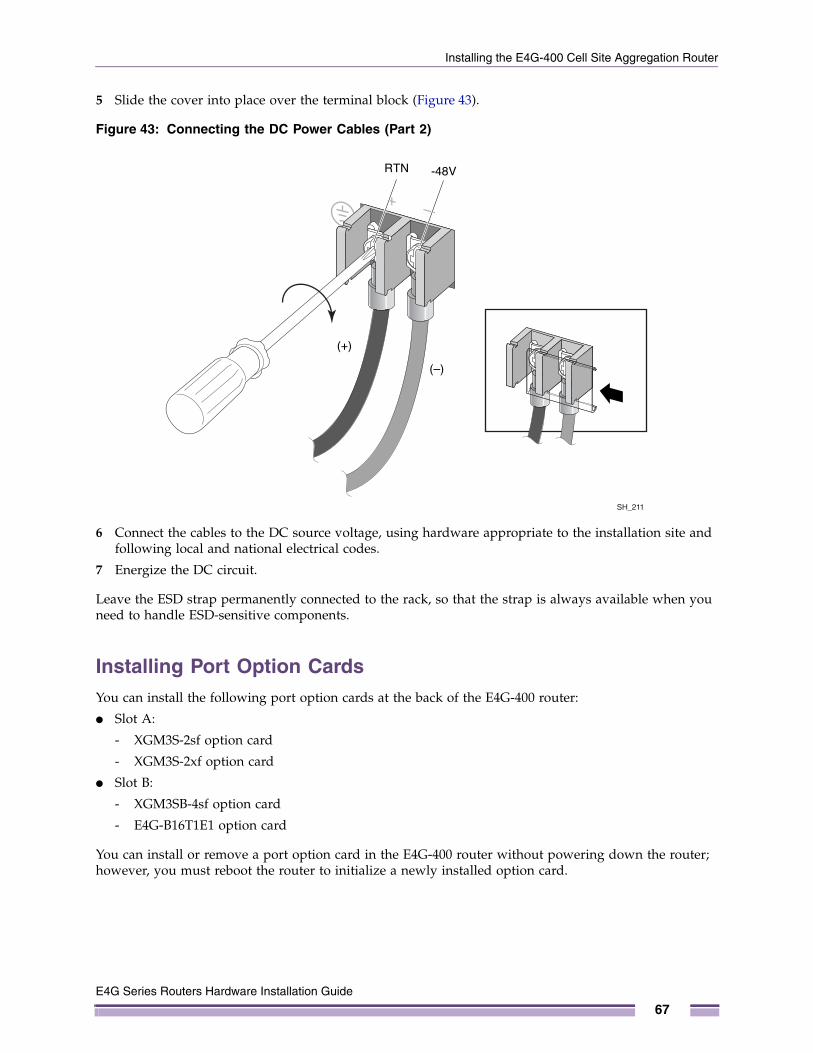
Installing the E4G-400 Cell Site Aggregation Router
5 Slide the cover into place over the terminal block (Figure 43).
Figure 43: Connecting the DC Power Cables (Part 2)
6 Connect the cables to the DC source voltage, using hardware appropriate to the installation site and following local and national electrical codes.
7 Energize the DC circuit.
Leave the ESD strap permanently connected to the rack, so that the strap is always available when you need to handle ESD-sensitive components.
Installing Port Option CardsYou can install the following port option cards at the back of the E4G-400 router:
● Slot A:
- XGM3S-2sf option card
- XGM3S-2xf option card
● Slot B:
- XGM3SB-4sf option card
- E4G-B16T1E1 option card
You can install or remove a port option card in the E4G-400 router without powering down the router; however, you must reboot the router to initialize a newly installed option card.
SH_211
(+)
(–)
RTN -48V
E4G Series Routers Hardware Installation Guide
67
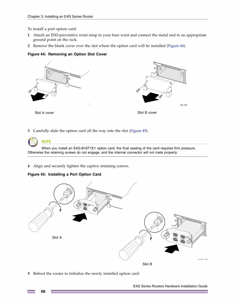
Chapter 3: Installing an E4G Series Router
To install a port option card:
1 Attach an ESD-preventive wrist strap to your bare wrist and connect the metal end to an appropriate ground point on the rack.
2 Remove the blank cover over the slot where the option card will be installed (Figure 44).
Figure 44: Removing an Option Slot Cover
3 Carefully slide the option card all the way into the slot (Figure 45).
NOTE
When you install an E4G-B16T1E1 option card, the final seating of the card requires firm pressure. Otherwise the retaining screws do not engage, and the internal connector will not mate properly.
4 Align and securely tighten the captive retaining screws.
Figure 45: Installing a Port Option Card
5 Reboot the router to initialize the newly installed option card.
SH_213 SH_216
Slot A cover Slot B cover
CSR_006
CSR_007
Slot A
Slot B
E4G Series Routers Hardware Installation Guide
68
Installing the E4G-400 Cell Site Aggregation Router
NOTE
Save the cover for later re-use in case you must remove the port option card and do not have a replacement card. An option slot must be covered to ensure satisfactory EMI levels and to maintain adequate airflow through the router.
Connecting Timing Cables to the E4G-400 RouterThe front panel of the E4G-400 router provides the types of cable connections listed below for connecting a Building Integrated Timing Supply (BITS) or GPS timing source.
● Two mini-BNC connectors labeled OUT
- 1 PPS or 8 KHz frame output
- 10 MHz or 2.048 MHz or 4.544 MHz output
● Two mini-BNC connectors labeled IN
- 1 PPS input
- 10 MHz input
● One RJ-45 connector for time-of-day (ToD) input/output or for RS-422 BITS input
To connect to the mini-BNC connectors, use a 50-ohm coaxial cable with a mini-BNC connector at one end and a standard BNC connector at the other.
To connect to the RJ-45 connector, use a twisted-pair cable with the pinouts listed in Table 19 on page 127.
Connecting Cables to the E4G-B16T1E1 ModuleThe ports on the E4G-B16T1E1 module are implemented as MRJ21 connectors. Each connector represents eight ports. Two cable types are available for these ports:
● MRJ21-to-RJ-45 fan-out cable (Extreme Networks part number 16220; see Figure 46)
● MRJ21-to-MRJ21 cable
CAUTION
When you handle the RJ21 cable for the E4G-B16T1E1 module, be careful not to bend the cable too sharply, especially at the connector. Make sure the cable extends at least 3 inches from the back panel of the module before it starts to bend.
E4G Series Routers Hardware Installation Guide
69
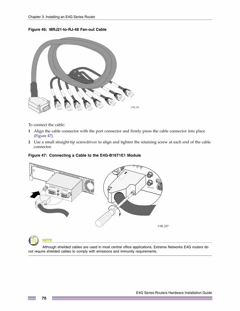
Chapter 3: Installing an E4G Series Router
Figure 46: MRJ21-to-RJ-48 Fan-out Cable
To connect the cable:
1 Align the cable connector with the port connector and firmly press the cable connector into place (Figure 47).
2 Use a small straight-tip screwdriver to align and tighten the retaining screw at each end of the cable connector.
Figure 47: Connecting a Cable to the E4G-B16T1E1 Module
NOTE
Although shielded cables are used in most central office applications, Extreme Networks E4G routers do not require shielded cables to comply with emissions and immunity requirements.
CSR_036
CSR_027
E4G Series Routers Hardware Installation Guide
70
Initial Startup
Initial StartupWhen an E4G series router is started for the first time, it can take up to 40 minutes for the clock function to stabilize and allow the T1 lines to hold synchronization.
Fans in the E4G-400 router may not start immediately when the unit is connected to power. The system cycles the fans on and off automatically in response to cooling requirements in the unit.
Initial Management AccessWhen you set up the router for the first time, you must connect to the console to access the router and perform initial security configuration. At this time you can also manually configure an IP address for the management VLAN.
Connecting Equipment to the Console PortConnection to the console port is used for direct local management. The console port settings are:
● Baud rate—9600
● Data bits—8
● Stop bit—1
● Parity—None
● Flow control—XON/XOFF
The terminal or PC with terminal-emulation software that you connect to an Extreme Networks switch must be configured with these settings. This procedure is described in the documentation supplied with the terminal.
A console cable is shipped with each E4G series router. For connector pinouts associated with the console ports, see “E4G-200 Series Connector Pinouts” on page 126.
To connect to the console port on the E4G-200 series router, use the provided Ethernet cable and DB-9-to-RJ-45 adapter.
To connect to the console port on the E4G-400 router, use the provided console cable.
A console-to-USB adapter may be needed if your PC or interface does not have a console port.
Logging In for the First TimeAfter your switch has completed all power on self-tests, it is operational. You can log in and configure an IP address for the management VLAN (named mgmt).
NOTE
The management port is part of the management VLAN by default.
E4G Series Routers Hardware Installation Guide
71
Chapter 3: Installing an E4G Series Router
To manually configure the IP settings:
1 Connect a terminal or PC with terminal-emulation software to the console port on the router.
2 At the terminal, press [Return] one or more times until you see the login prompt.
3 At the login prompt, enter the default user name admin to log on with administrator privileges. For example:
login: admin
Administrator capabilities allow you to access all switch functions.
4 The system will ask a series of questions about the default management settings, which allow all forms of management access for convenience in setting the initial configuration. Answer each question based on the level of security needed for the particular management access type.
NOTE
For more information about logging in to the switch and configuring switch management access, see the ExtremeXOS Concepts Guide.
5 At the password prompt, press [Return].
The default user name admin has no password assigned to it. When you have successfully logged on to the system, the command line prompt displays the system name (for example, e4g200>) in the prompt.
NOTE
For more information about how to assign a specific system name, see the ExtremeXOS Concepts Guide.
6 Assign an IP address and subnetwork mask for VLAN mgmt by typing:
configure mgmt ipaddress 123.45.67.8 255.255.255.0
Your changes take effect immediately.
7 Save your configuration changes so that they will be in effect after the next system reboot by typing:
save
The configuration is saved to the configuration database of the router.
NOTE
For more information about saving configuration changes, see the ExtremeXOS Concepts Guide.
8 When you are finished with these tasks, log out of the router by typing:
logout
E4G Series Routers Hardware Installation Guide
72
PART
Maintenance

4
E4G Series Routers Hardware
CHAPTER
Maintenance Procedures
This chapter provides instructions for maintenance procedures on the E4G series routers and includes the following sections:
● Replacing an AC Power Supply in the E4G-400 Router on page 75
● Replacing a DC Power Supply in the E4G-400 Router on page 78
● Replacing a Fan Module in the E4G-400 Router on page 86
● Replacing Optional Ports in the E4G-400 Router on page 87
● Replacing a Clock Module in the E4G-200 Series Router on page 88
● Replacing a T1E1 Module in the E4G-200 Series Router on page 89
● Removing an E4G-200 Series Router from an Equipment Rack on page 90
● Removing an E4G-400 Router from an Equipment Rack on page 91
NOTE
If you will be working near multiple E4G-400 routers for an extended time, Extreme Networks recommends that you wear hearing protection. When all the fans are operating, the noise level can be in excess of 7.2 B(A) Declared Sound Power or 69 decibels Sound Power.
Replacing an AC Power Supply in the E4G-400 RouterThe E4G-400 routers have two bays for hot-swappable power supplies. In a router with a redundant power configuration, you can replace one AC power supply without powering down the router.
You need the following tools and materials to replace an AC power supply:
● Thermal protective gloves
● AC power cord, if you will not be re-using the cord from the removed power supply
An AC power cord is not included with the AC power supply. You must obtain a power supply cord that meets the requirements listed under “Selecting Power Supply Cords” on page 99.
Installation Guide
75
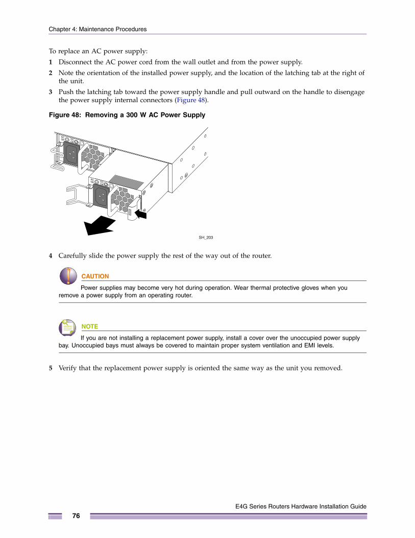
Chapter 4: Maintenance Procedures
To replace an AC power supply:
1 Disconnect the AC power cord from the wall outlet and from the power supply.
2 Note the orientation of the installed power supply, and the location of the latching tab at the right of the unit.
3 Push the latching tab toward the power supply handle and pull outward on the handle to disengage the power supply internal connectors (Figure 48).
Figure 48: Removing a 300 W AC Power Supply
4 Carefully slide the power supply the rest of the way out of the router.
CAUTION
Power supplies may become very hot during operation. Wear thermal protective gloves when you remove a power supply from an operating router.
NOTE
If you are not installing a replacement power supply, install a cover over the unoccupied power supply bay. Unoccupied bays must always be covered to maintain proper system ventilation and EMI levels.
5 Verify that the replacement power supply is oriented the same way as the unit you removed.
SH_203
E4G Series Routers Hardware Installation Guide
76
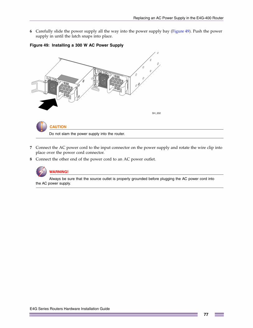
Replacing an AC Power Supply in the E4G-400 Router
6 Carefully slide the power supply all the way into the power supply bay (Figure 49). Push the power supply in until the latch snaps into place.
Figure 49: Installing a 300 W AC Power Supply
CAUTION
Do not slam the power supply into the router.
7 Connect the AC power cord to the input connector on the power supply and rotate the wire clip into place over the power cord connector.
8 Connect the other end of the power cord to an AC power outlet.
WARNING!
Always be sure that the source outlet is properly grounded before plugging the AC power cord into the AC power supply.
SH_202
E4G Series Routers Hardware Installation Guide
77
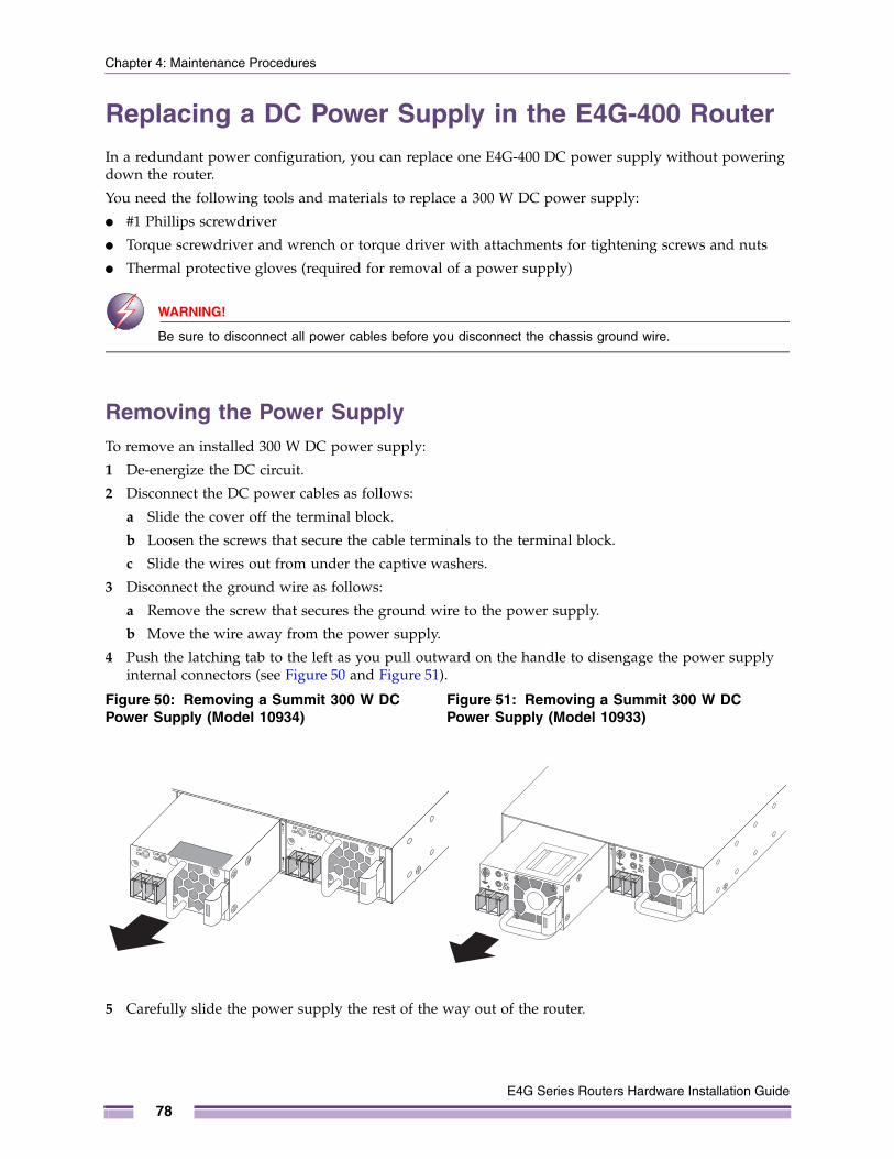
Chapter 4: Maintenance Procedures
Replacing a DC Power Supply in the E4G-400 RouterIn a redundant power configuration, you can replace one E4G-400 DC power supply without powering down the router.
You need the following tools and materials to replace a 300 W DC power supply:
● #1 Phillips screwdriver
● Torque screwdriver and wrench or torque driver with attachments for tightening screws and nuts
● Thermal protective gloves (required for removal of a power supply)
WARNING!
Be sure to disconnect all power cables before you disconnect the chassis ground wire.
Removing the Power SupplyTo remove an installed 300 W DC power supply:
1 De-energize the DC circuit.
2 Disconnect the DC power cables as follows:
a Slide the cover off the terminal block.
b Loosen the screws that secure the cable terminals to the terminal block.
c Slide the wires out from under the captive washers.
3 Disconnect the ground wire as follows:
a Remove the screw that secures the ground wire to the power supply.
b Move the wire away from the power supply.
4 Push the latching tab to the left as you pull outward on the handle to disengage the power supply internal connectors (see Figure 50 and Figure 51).
5 Carefully slide the power supply the rest of the way out of the router.
Figure 50: Removing a Summit 300 W DC Power Supply (Model 10934)
Figure 51: Removing a Summit 300 W DC Power Supply (Model 10933)
E4G Series Routers Hardware Installation Guide
78
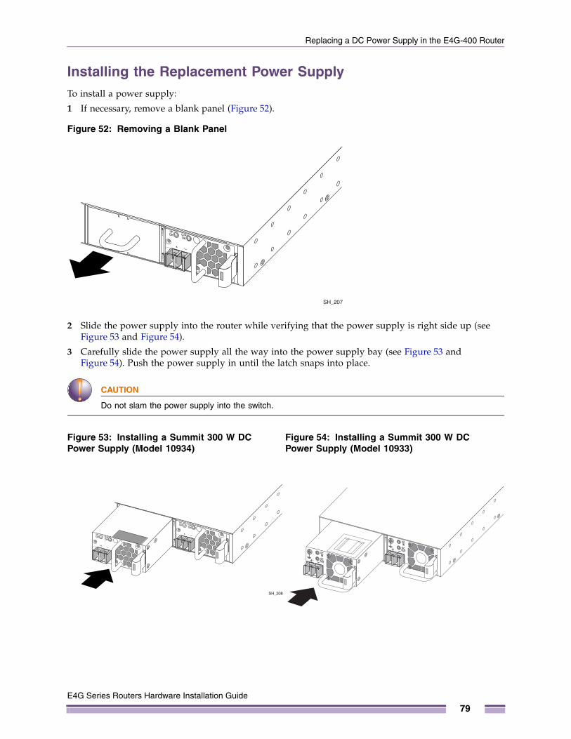
Replacing a DC Power Supply in the E4G-400 Router
Installing the Replacement Power SupplyTo install a power supply:
1 If necessary, remove a blank panel (Figure 52).
Figure 52: Removing a Blank Panel
2 Slide the power supply into the router while verifying that the power supply is right side up (see Figure 53 and Figure 54).
3 Carefully slide the power supply all the way into the power supply bay (see Figure 53 and Figure 54). Push the power supply in until the latch snaps into place.
CAUTION
Do not slam the power supply into the switch.
Figure 53: Installing a Summit 300 W DC Power Supply (Model 10934)
Figure 54: Installing a Summit 300 W DC Power Supply (Model 10933)
SH_207
SH_208
E4G Series Routers Hardware Installation Guide
79
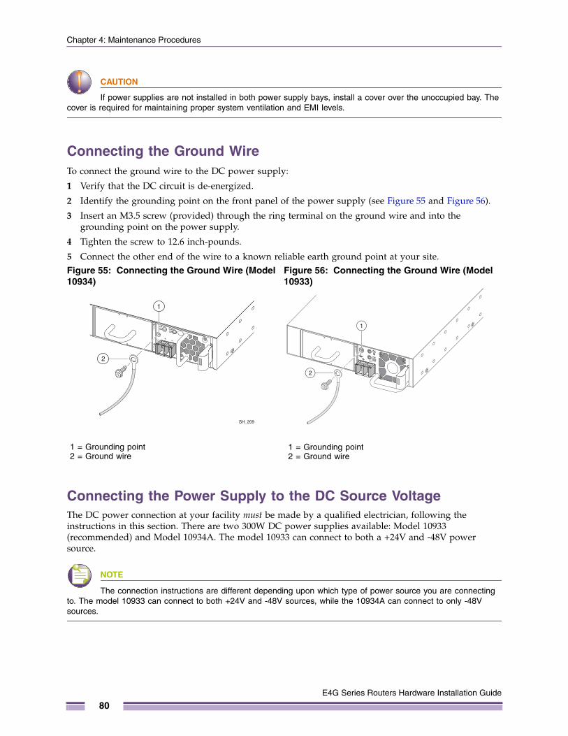
Chapter 4: Maintenance Procedures
CAUTION
If power supplies are not installed in both power supply bays, install a cover over the unoccupied bay. The cover is required for maintaining proper system ventilation and EMI levels.
Connecting the Ground WireTo connect the ground wire to the DC power supply:
1 Verify that the DC circuit is de-energized.
2 Identify the grounding point on the front panel of the power supply (see Figure 55 and Figure 56).
3 Insert an M3.5 screw (provided) through the ring terminal on the ground wire and into the grounding point on the power supply.
4 Tighten the screw to 12.6 inch-pounds.
5 Connect the other end of the wire to a known reliable earth ground point at your site.
Connecting the Power Supply to the DC Source VoltageThe DC power connection at your facility must be made by a qualified electrician, following the instructions in this section. There are two 300W DC power supplies available: Model 10933 (recommended) and Model 10934A. The model 10933 can connect to both a +24V and -48V power source.
NOTE
The connection instructions are different depending upon which type of power source you are connecting to. The model 10933 can connect to both +24V and -48V sources, while the 10934A can connect to only -48V sources.
Figure 55: Connecting the Ground Wire (Model 10934)
Figure 56: Connecting the Ground Wire (Model 10933)
SH_209
1
2
1 = Grounding point2 = Ground wire
1
2
1 = Grounding point2 = Ground wire
E4G Series Routers Hardware Installation Guide
80
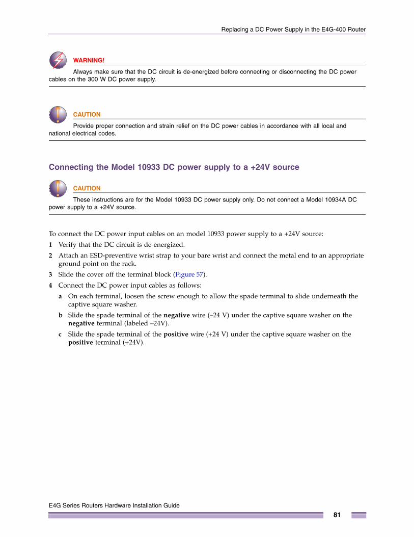
Replacing a DC Power Supply in the E4G-400 Router
WARNING!
Always make sure that the DC circuit is de-energized before connecting or disconnecting the DC power cables on the 300 W DC power supply.
CAUTION
Provide proper connection and strain relief on the DC power cables in accordance with all local and national electrical codes.
Connecting the Model 10933 DC power supply to a +24V source
CAUTION
These instructions are for the Model 10933 DC power supply only. Do not connect a Model 10934A DC power supply to a +24V source.
To connect the DC power input cables on an model 10933 power supply to a +24V source:
1 Verify that the DC circuit is de-energized.
2 Attach an ESD-preventive wrist strap to your bare wrist and connect the metal end to an appropriate ground point on the rack.
3 Slide the cover off the terminal block (Figure 57).
4 Connect the DC power input cables as follows:
a On each terminal, loosen the screw enough to allow the spade terminal to slide underneath the captive square washer.
b Slide the spade terminal of the negative wire (–24 V) under the captive square washer on the negative terminal (labeled –24V).
c Slide the spade terminal of the positive wire (+24 V) under the captive square washer on the positive terminal (+24V).
E4G Series Routers Hardware Installation Guide
81
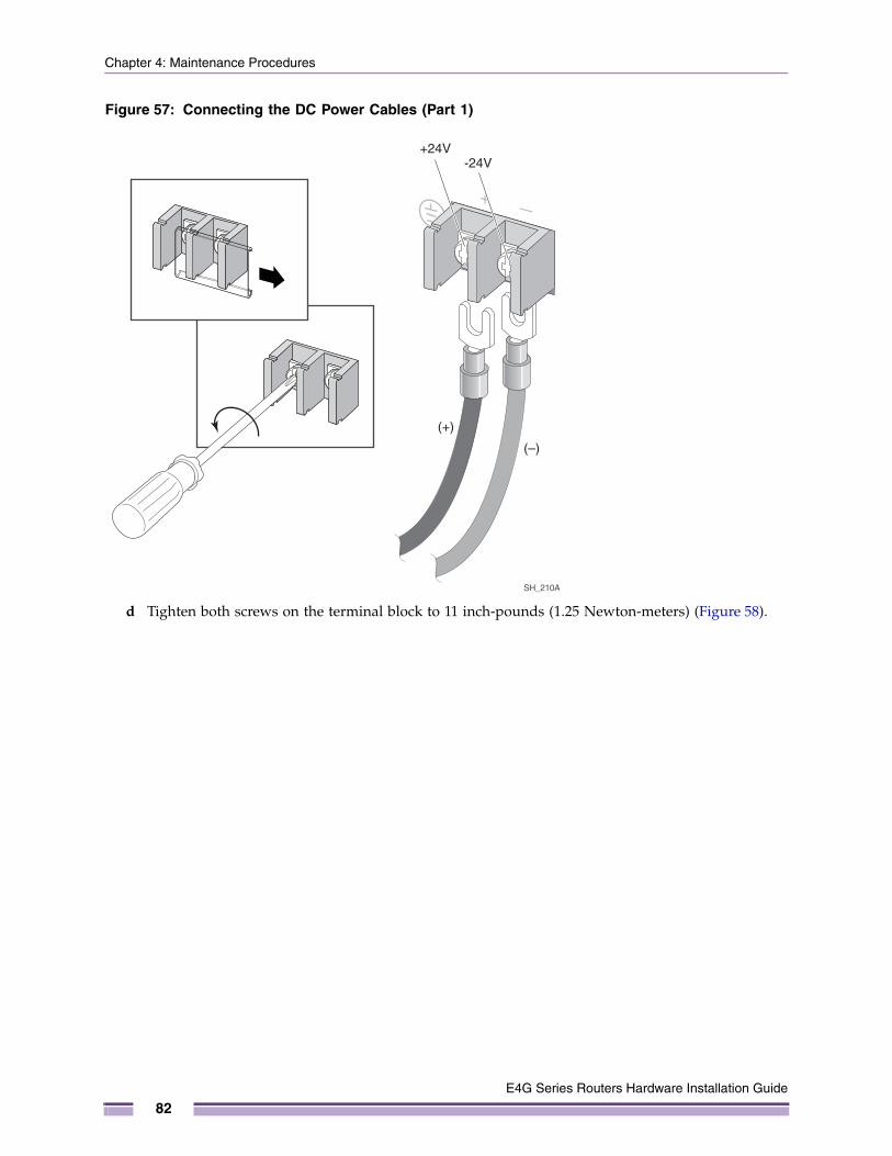
Chapter 4: Maintenance Procedures
Figure 57: Connecting the DC Power Cables (Part 1)
d Tighten both screws on the terminal block to 11 inch-pounds (1.25 Newton-meters) (Figure 58).
(+)
(–)
+24V-24V
SH_210A
E4G Series Routers Hardware Installation Guide
82
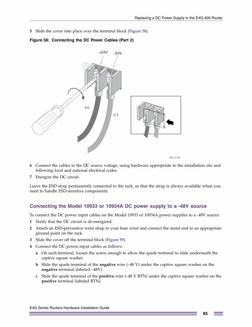
Replacing a DC Power Supply in the E4G-400 Router
5 Slide the cover into place over the terminal block (Figure 58).
Figure 58: Connecting the DC Power Cables (Part 2)
6 Connect the cables to the DC source voltage, using hardware appropriate to the installation site and following local and national electrical codes.
7 Energize the DC circuit.
Leave the ESD strap permanently connected to the rack, so that the strap is always available when you need to handle ESD-sensitive components.
Connecting the Model 10933 or 10934A DC power supply to a -48V source
To connect the DC power input cables on the Model 10933 or 10934A power supplies to a -48V source:
1 Verify that the DC circuit is de-energized.
2 Attach an ESD-preventive wrist strap to your bare wrist and connect the metal end to an appropriate ground point on the rack.
3 Slide the cover off the terminal block (Figure 59).
4 Connect the DC power input cables as follows:
a On each terminal, loosen the screw enough to allow the spade terminal to slide underneath the captive square washer.
b Slide the spade terminal of the negative wire (–48 V) under the captive square washer on the negative terminal (labeled –48V).
c Slide the spade terminal of the positive wire (–48 V RTN) under the captive square washer on the positive terminal (labeled RTN).
SH_211A
(+)
(–)
+24V -24V
E4G Series Routers Hardware Installation Guide
83
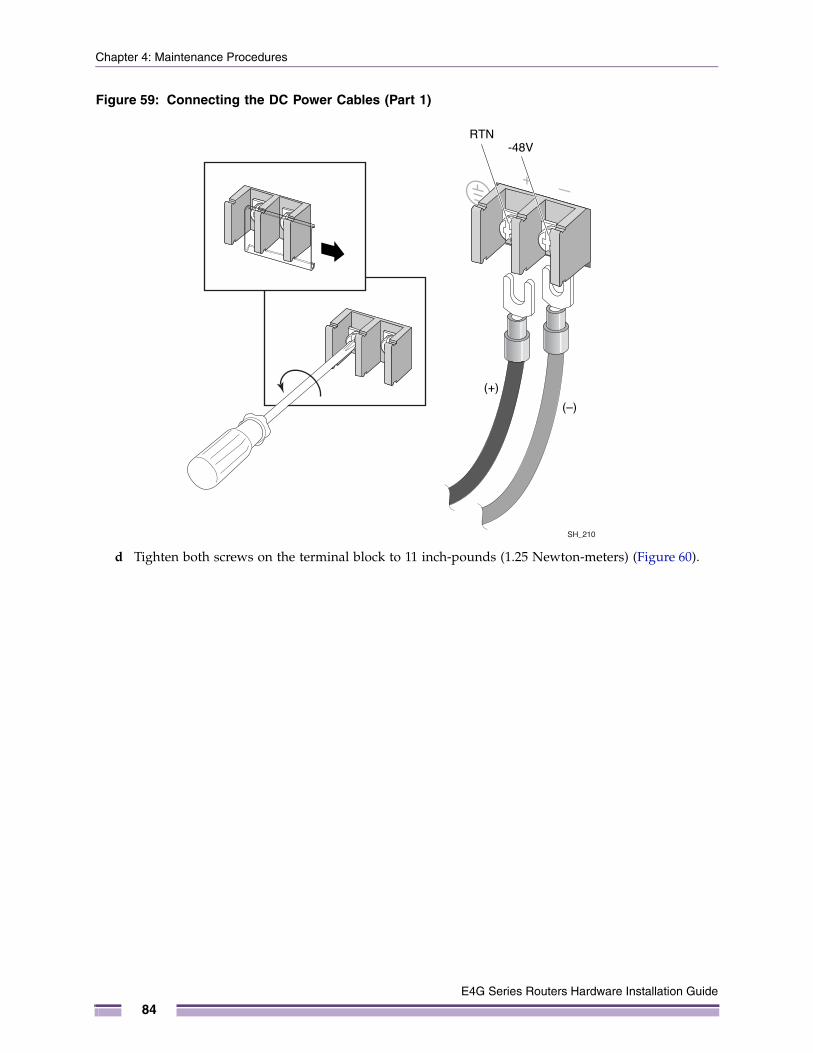
Chapter 4: Maintenance Procedures
Figure 59: Connecting the DC Power Cables (Part 1)
d Tighten both screws on the terminal block to 11 inch-pounds (1.25 Newton-meters) (Figure 60).
(+)
(–)
RTN-48V
SH_210
E4G Series Routers Hardware Installation Guide
84
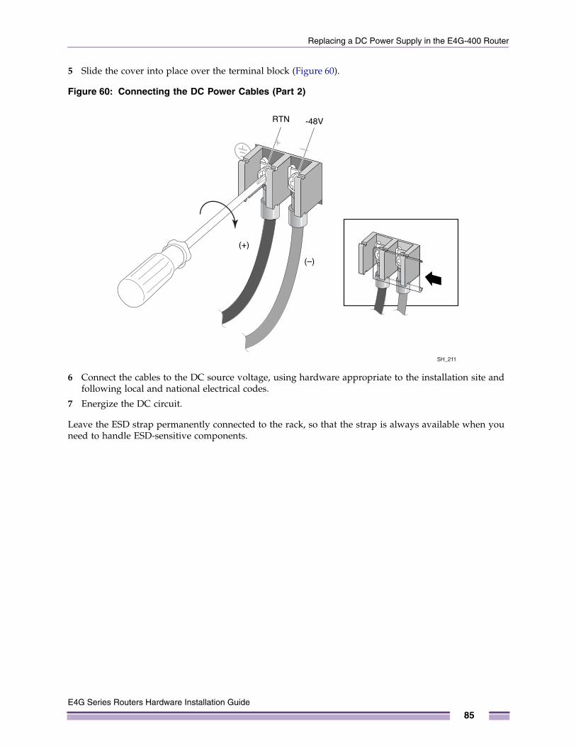
Replacing a DC Power Supply in the E4G-400 Router
5 Slide the cover into place over the terminal block (Figure 60).
Figure 60: Connecting the DC Power Cables (Part 2)
6 Connect the cables to the DC source voltage, using hardware appropriate to the installation site and following local and national electrical codes.
7 Energize the DC circuit.
Leave the ESD strap permanently connected to the rack, so that the strap is always available when you need to handle ESD-sensitive components.
SH_211
(+)
(–)
RTN -48V
E4G Series Routers Hardware Installation Guide
85
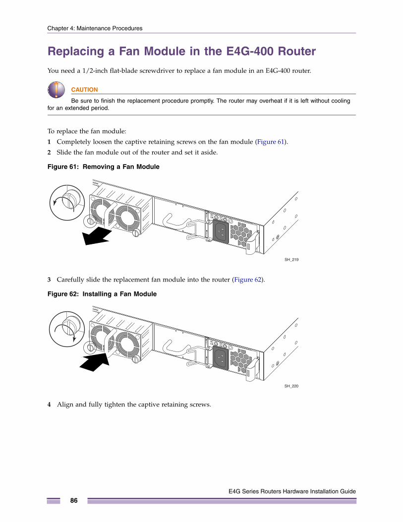
Chapter 4: Maintenance Procedures
Replacing a Fan Module in the E4G-400 RouterYou need a 1/2-inch flat-blade screwdriver to replace a fan module in an E4G-400 router.
CAUTION
Be sure to finish the replacement procedure promptly. The router may overheat if it is left without cooling for an extended period.
To replace the fan module:
1 Completely loosen the captive retaining screws on the fan module (Figure 61).
2 Slide the fan module out of the router and set it aside.
Figure 61: Removing a Fan Module
3 Carefully slide the replacement fan module into the router (Figure 62).
Figure 62: Installing a Fan Module
4 Align and fully tighten the captive retaining screws.
SH_219
SH_220
E4G Series Routers Hardware Installation Guide
86
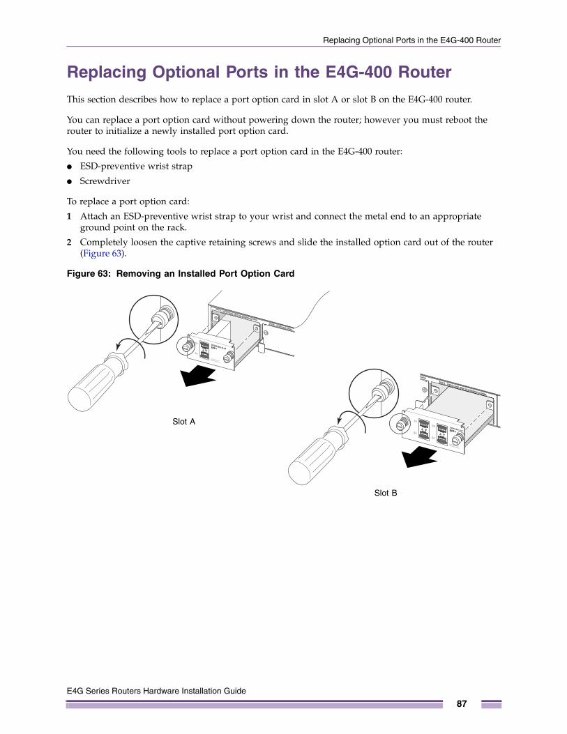
Replacing Optional Ports in the E4G-400 Router
Replacing Optional Ports in the E4G-400 RouterThis section describes how to replace a port option card in slot A or slot B on the E4G-400 router.
You can replace a port option card without powering down the router; however you must reboot the router to initialize a newly installed port option card.
You need the following tools to replace a port option card in the E4G-400 router:
● ESD-preventive wrist strap
● Screwdriver
To replace a port option card:
1 Attach an ESD-preventive wrist strap to your wrist and connect the metal end to an appropriate ground point on the rack.
2 Completely loosen the captive retaining screws and slide the installed option card out of the router (Figure 63).
Figure 63: Removing an Installed Port Option Card
CSR_033Slot A
CSR_03Slot B
E4G Series Routers Hardware Installation Guide
87
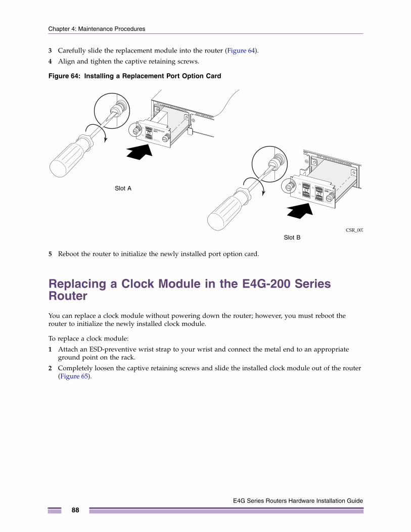
Chapter 4: Maintenance Procedures
3 Carefully slide the replacement module into the router (Figure 64).
4 Align and tighten the captive retaining screws.
Figure 64: Installing a Replacement Port Option Card
5 Reboot the router to initialize the newly installed port option card.
Replacing a Clock Module in the E4G-200 Series RouterYou can replace a clock module without powering down the router; however, you must reboot the router to initialize the newly installed clock module.
To replace a clock module:
1 Attach an ESD-preventive wrist strap to your wrist and connect the metal end to an appropriate ground point on the rack.
2 Completely loosen the captive retaining screws and slide the installed clock module out of the router (Figure 65).
CSR_006
Slot A
CSR_007Slot B
E4G Series Routers Hardware Installation Guide
88
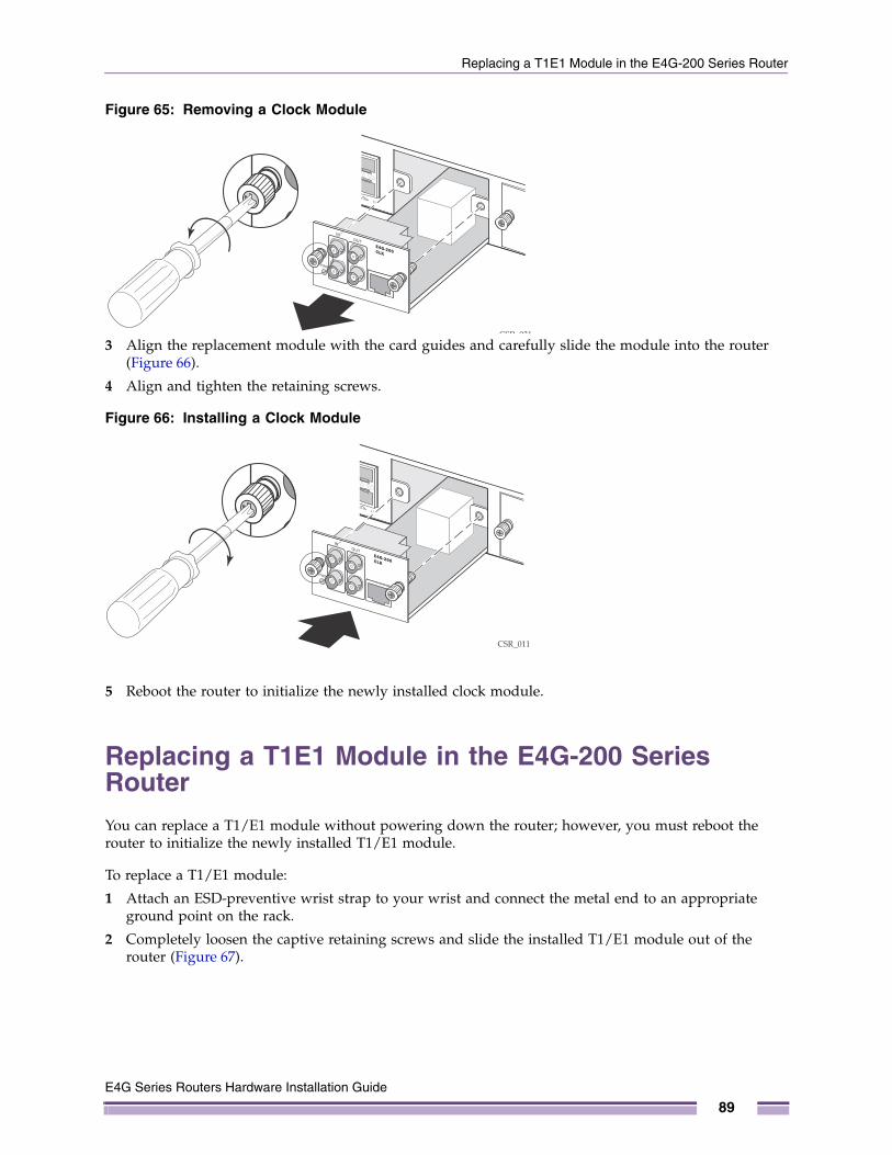
Replacing a T1E1 Module in the E4G-200 Series Router
Figure 65: Removing a Clock Module
3 Align the replacement module with the card guides and carefully slide the module into the router (Figure 66).
4 Align and tighten the retaining screws.
Figure 66: Installing a Clock Module
5 Reboot the router to initialize the newly installed clock module.
Replacing a T1E1 Module in the E4G-200 Series RouterYou can replace a T1/E1 module without powering down the router; however, you must reboot the router to initialize the newly installed T1/E1 module.
To replace a T1/E1 module:
1 Attach an ESD-preventive wrist strap to your wrist and connect the metal end to an appropriate ground point on the rack.
2 Completely loosen the captive retaining screws and slide the installed T1/E1 module out of the router (Figure 67).
CSR 031
CSR_011
E4G Series Routers Hardware Installation Guide
89
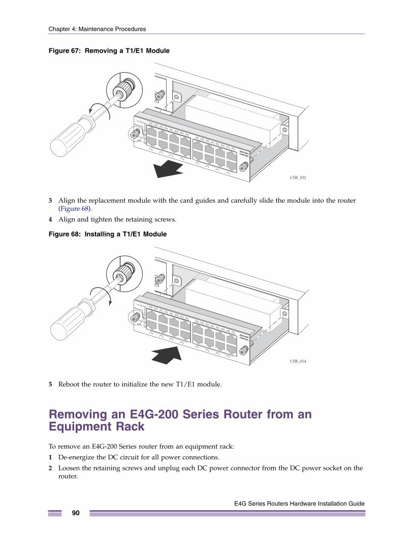
Chapter 4: Maintenance Procedures
Figure 67: Removing a T1/E1 Module
3 Align the replacement module with the card guides and carefully slide the module into the router (Figure 68).
4 Align and tighten the retaining screws.
Figure 68: Installing a T1/E1 Module
5 Reboot the router to initialize the new T1/E1 module.
Removing an E4G-200 Series Router from an Equipment RackTo remove an E4G-200 Series router from an equipment rack:
1 De-energize the DC circuit for all power connections.
2 Loosen the retaining screws and unplug each DC power connector from the DC power socket on the router.
CSR_032
CSR_014
E4G Series Routers Hardware Installation Guide
90
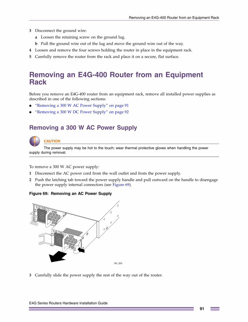
Removing an E4G-400 Router from an Equipment Rack
3 Disconnect the ground wire:
a Loosen the retaining screw on the ground lug.
b Pull the ground wire out of the lug and move the ground wire out of the way.
4 Loosen and remove the four screws holding the router in place in the equipment rack.
5 Carefully remove the router from the rack and place it on a secure, flat surface.
Removing an E4G-400 Router from an Equipment RackBefore you remove an E4G-400 router from an equipment rack, remove all installed power supplies as described in one of the following sections:
● “Removing a 300 W AC Power Supply” on page 91
● “Removing a 300 W DC Power Supply” on page 92
Removing a 300 W AC Power Supply
CAUTION
The power supply may be hot to the touch; wear thermal protective gloves when handling the power supply during removal.
To remove a 300 W AC power supply:
1 Disconnect the AC power cord from the wall outlet and from the power supply.
2 Push the latching tab toward the power supply handle and pull outward on the handle to disengage the power supply internal connectors (see Figure 69).
Figure 69: Removing an AC Power Supply
3 Carefully slide the power supply the rest of the way out of the router.
SH_203
E4G Series Routers Hardware Installation Guide
91
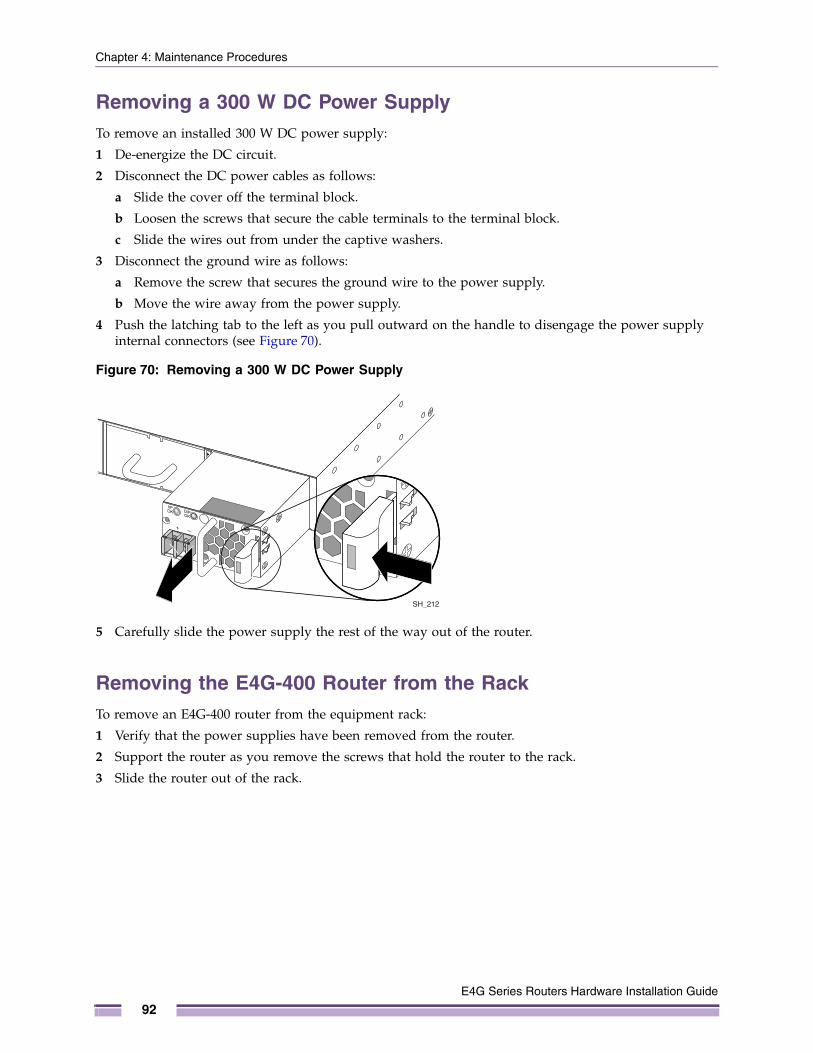
Chapter 4: Maintenance Procedures
Removing a 300 W DC Power SupplyTo remove an installed 300 W DC power supply:
1 De-energize the DC circuit.
2 Disconnect the DC power cables as follows:
a Slide the cover off the terminal block.
b Loosen the screws that secure the cable terminals to the terminal block.
c Slide the wires out from under the captive washers.
3 Disconnect the ground wire as follows:
a Remove the screw that secures the ground wire to the power supply.
b Move the wire away from the power supply.
4 Push the latching tab to the left as you pull outward on the handle to disengage the power supply internal connectors (see Figure 70).
Figure 70: Removing a 300 W DC Power Supply
5 Carefully slide the power supply the rest of the way out of the router.
Removing the E4G-400 Router from the RackTo remove an E4G-400 router from the equipment rack:
1 Verify that the power supplies have been removed from the router.
2 Support the router as you remove the screws that hold the router to the rack.
3 Slide the router out of the rack.
SH_212
E4G Series Routers Hardware Installation Guide
92

PART
Appendices


A
E4G Series Routers Hardware
APPEND IX
Safety Information
WARNING!
Read the safety information in this appendix thoroughly before installing Extreme Networks products. Failure to follow this safety information can lead to personal injury or damage to the equipment.
Only trained and qualified service personnel (as defined in IEC 60950-1 and AS/NZS 3260) should install, replace, or perform service to Extreme Networks switches and their components. Qualified personnel have read all related installation manuals, have the technical training and experience necessary to be aware of the hazards to which they are exposed in performing a task, and are aware of measures to minimize the danger to themselves or other persons.
If you are in the USA, install the system in accordance with the U.S. National Electrical Code (NEC).
This appendix includes the following sections:
● Considerations Before Installing on page 96
● General Safety Precautions on page 96
● Maintenance Safety on page 97
● Cable Routing for LAN Systems on page 97
● Installing Power Supply Units and Connecting Power on page 98
● Selecting Power Supply Cords on page 99
● Battery Replacement and Disposal on page 100
● Fiber Optic Ports and Optical Safety on page 100
● Safety Information for the E4G Series Routers on page 101
● Sicherheitshinweise on page 102 (safety information in German)
Installation Guide
95

Appendix A: Safety Information
Considerations Before InstallingConsider the following items before you install equipment.
● For equipment designed to operate in a typical Telco environment that is environmentally controlled, choose an indoor area that has the following characteristics:
- Temperature-controlled and humidity-controlled, such that the maximum ambient room temperature shall not exceed the temperature specified in the product data sheet
- Clean and free from airborne materials that can conduct electricity
- Well ventilated and away from sources of heat including direct sunlight
- Away from sources of vibration or physical shock
- Isolated from strong electromagnetic fields produced by electrical devices
- Secured, enclosed, and restricted-access, ensuring that only trained and qualified service personnel have access to the equipment
● For equipment designed to be installed in environments that are not environmentally controlled, such as outdoor enclosures, see the product data sheet or Appendix B of this guide for environmental conditions, temperature, and humidity.
● Establish at least 3 inches clearance on all sides for effective ventilation. Do not obstruct air intake vents or ventilation grills on the front, side, or rear panel. Locate the system away from heat sources.
● Make sure that your equipment is placed in an area that accommodates the power consumption and component heat dissipation specifications.
● Make sure that your power supplies meet the site DC power or AC power requirements of all the network equipment.
● Racks for Extreme Networks equipment must be permanently attached to the floor. Failure to stabilize the rack can cause the rack to tip over when the equipment is removed for servicing.
● Do not operate the system unless all modules, faceplates, front covers, and rear covers are in place. Blank faceplates and cover panels are required for the following functions:
- Preventing exposure to hazardous voltages and currents inside the equipment
- Containing electromagnetic interference (EMI) that might disrupt other equipment
- Directing the flow of cooling air through the equipment
● Ultimate disposal of this product should be handled according to all national laws and regulations.
General Safety PrecautionsFollow these guidelines:
● Do not try to lift objects that you think are too heavy for you.
● When you install equipment in a rack, load heavier devices in the lower half of the rack first to avoid making the rack top-heavy.
● Use only tools and equipment that are in perfect condition. Do not use equipment with visible damage.
● Route cables in a manner that prevents possible damage to the cables and avoids causing accidents, such as tripping.
● Do not place a monitor or other objects on top of the equipment. The chassis cover is not designed to support weight.
E4G Series Routers Hardware Installation Guide
96
Maintenance Safety
● To reduce the risk of fire, use only #26 AWG or larger telecommunications line cord. Use only copper conductors.
● Do not work on the system or connect or disconnect cables during periods of lightning activity.
● This equipment must be grounded. Never defeat the ground conductor or operate the equipment in the absence of a suitably installed ground conductor.
Maintenance SafetyWhen you perform maintenance procedures on Extreme Networks equipment, follow these recommendations:
● Use only authorized accessories or components that are approved for use with this system. Failure to follow these instructions may damage the equipment or violate required safety and EMC regulations.
● This system contains no customer serviceable components. Do not attempt to repair a chassis, power supply, module, or other component. In the event of failure, return the defective unit to Extreme Networks for repair or replacement, unless otherwise instructed by an Extreme Networks representative.
● To remove power from the system, you must unplug all power cords from wall outlets. The power cord is the disconnect device to the main power source.
● Disconnect all power cords before working near power supplies, unless you are instructed otherwise by a product-specific maintenance procedure.
● Replace a power cord immediately if it shows any signs of damage.
● When you work with optical devices, power supplies, or other modular accessories, put on an ESD-preventive wrist strap to reduce the risk of electronic damage to the equipment. Connect the other end of the strap to an appropriate grounding point on the equipment rack or to an ESD jack on the chassis if one is provided. Leave the ESD-preventive wrist strap permanently attached to the equipment rack or chassis so that it is always available when you need to handle components that are sensitive to ESD.
● Install all cables in a manner that avoids strain. Use tie wraps or other strain relief devices.
Cable Routing for LAN SystemsExtreme Networks equipment meets the requirements for LAN system equipment. LAN systems are designed only for intra-building installations; that is, cable runs between devices must be in the same building as the connected units.
As allowed in the USA by the National Electrical Code (NEC), this equipment can be connected between buildings if any one of the following conditions is true:
● Cable runs between buildings are less then 140 feet long.
● Cable runs between buildings are directly buried.
● Cable runs between buildings are in an underground conduit, where a continuous metallic cable shield or a continuous metallic conduit containing the cable is bonded to each building grounding electrode system.
E4G Series Routers Hardware Installation Guide
97

Appendix A: Safety Information
CAUTION
Failure follow these requirements for cable routing conditions may expose the user to electrical shock and may expose the unit to damage that can cause errors.
WARNING!
The Ethernet ports of the equipment and its sub-assemblies are suitable only for intra-building connections (within the same building) or for connections to unexposed wiring or cabling. (See the conditions listed above.) The Ethernet ports of this equipment or its sub-assemblies must not be metallically connected to interfaces that connect to the outside plant (OSP) or its wiring. Ethernet interfaces are designed for use only as intra-building interfaces (described as Type 2 or Type 4 ports in GR-1089-CORE, Issue 6) and require isolation from the exposed OSP wiring. The addition of Primary Protectors is not sufficient protection to connect these interfaces metallically to OSP wiring.
This warning does not apply to T1/E1 ports because T1/E1 ports have built-in isolation and surge protection that allows them to be connected to OSP wiring.
Installing Power Supply Units and Connecting PowerFor the ratings and power requirements of each power supply unit or router see Appendix B or the data sheet for the equipment at http://www.extremenetworks.com.
WARNING!
Be sure to satisfy the requirements listed in this section when you install Extreme Networks power supplies or connect power.
When you install any power supply:
● Do not use excessive force when you insert a power supply into the bay.
● Do not attempt to open the power supply enclosure for any reason; the power supply does not contain user-serviceable parts. In the event of failure, return the defective power supply to Extreme Networks for repair or replacement.
● Do not put your hand into an open power supply bay when a power supply is not present. An empty power supply bay requires a cover at all times.
● Before you work on equipment that is connected to power lines, remove all jewelry, including watches. Metal objects heat up when they are connected to power and ground and can cause serious burns or weld the metal object to the terminals.
● An electrical arc can occur when you connect or disconnect the power with power applied. This could cause an explosion in hazardous area installations. Be sure that power is removed from the device.
● When you install or replace equipment, always make the ground connection first and disconnect the ground connection last.
E4G Series Routers Hardware Installation Guide
98

Selecting Power Supply Cords
When you install AC power supplies:
● For switches with field-replaceable power supplies, do not connect the power supply to an electrical source when the power supply is not installed in the switch; doing so would expose a hazardous energy and poses a potential shock and fire hazard.
● Plug power supplies only into properly grounded electrical outlets to help prevent electrical shock and to comply with international safety standards.
● Use only power cords that are certified for use within the country of use. Do not attempt to modify AC power cords.
● Make sure that the voltage and frequency of your power outlet match the system electrical ratings for the equipment. The building and/or power source must provide overload protection.
● Use a surge suppressor, line conditioner, or uninterruptible power supply to protect the system from momentary increases or decreases in electrical power.
● When multiple power supplies are used with a system, connect each power supply to a different, independent over-current protection device, such as a circuit breaker. If a single power source fails, it will affect only that power supply to which it is connected. See the data sheet of the power supply for proper sizing of the circuit breaker.
● Extreme Networks AC power supplies do not have switches for turning the unit on and off. Remove all wall plugs from the electrical outlet to disconnect the power. Make sure that these connections are easily accessible.
When you install DC power supplies or connect DC power:
● Making the connection to your facility DC source voltage must be performed by a qualified, licensed electrician.
● Extreme Networks DC power supplies and DC-powered devices do not have switches for turning the unit on and off. Make sure that the DC circuit is de-energized before connecting or disconnecting the DC power cord at the DC power input socket.
● Do not connect a DC power supply to the DC source power when the power supply is not installed in the chassis; doing so would expose a hazardous energy and poses a potential shock and fire hazard.
● Connect the system or power supply only to a DC power source that complies with the safety extra-low voltage (SELV) requirements in IEC 60950-based safety standards.
● DC-powered equipment must be installed in a restricted-access area to ensure that only trained and qualified service personnel have access to the equipment. A restricted-access area can be entered only through the use of a special tool, lock and key, or other means of security.
NOTE
Building codes vary worldwide; therefore, Extreme Networks strongly recommends that you consult an electrical contractor to ensure proper equipment grounding and power distribution for your specific installation and country.
Selecting Power Supply CordsExtreme Networks does not include AC power input cords in the product box. You can purchase a power cord for your product and for your specific country from your local Extreme Networks Channel Account Manager or Sales Manager, or you can purchase a cord from your local supplier. Requirements for the power cord are listed in Appendix B of this guide.
E4G Series Routers Hardware Installation Guide
99
Appendix A: Safety Information
To locate a Sales Manager or Partner in your region visit:
http://www.extremenetworks.com/how-to-buy/how-to-buy.aspx
NOTE
This equipment is not intended to be directly powered by power distribution systems where phase-phase voltages exceed 240V AC (2P+PE), such as those used in Norway, France, and other countries. For these applications it is recommended that a transformer be used to step down the voltage to < 240V AC from phase-phase, or that you make a connection to a (P+N+PE) power distribution where voltages do not exceed 240V AC.
All installations should confirm that the product is reliably grounded according to the country’s local electrical codes.
Battery Replacement and DisposalBatteries included with Extreme Networks products are encapsulated and must be replaced by qualified Extreme Service personnel only. Contact your Extreme Service personnel for product replacement. Do not attempt to replace the battery. If these instructions are disregarded and replacement of these batteries is attempted, the following guidelines must be followed to avoid danger of explosion:
● Replace with the same or equivalent battery type as recommended by the battery manufacturer.
● Dispose of the battery in accordance with the battery manufacturer’s recommendation.
Fiber Optic Ports and Optical SafetyThe following safety warnings apply to all optical devices used in Extreme Networks equipment that are removable or directly installed in an I/O module or chassis system. Such devices include but are not limited to gigabit interface converters (GBICs), small form factor pluggable (SFP) modules (or mini-GBICs), QSFP+ modules, XENPAK transceivers, and XFP laser optic modules.
WARNING!
Laser optic modules become very hot after prolonged use. Be careful when removing a laser optic module from the chassis or option card. If the laser optic module is too hot to touch, disengage the laser optic module and allow it to cool before removing it completely.
WARNING!
When you work with laser optic modules, always take the precautions listed below to avoid exposure to hazardous radiation.
E4G Series Routers Hardware Installation Guide
100
Safety Information for the E4G Series Routers
● Never look at the transmit LED/laser through a magnifying device while the LED or laser is powered on.
● Never look directly at a fiber port on the router or at the ends of a fiber cable when they are powered on.
● Invisible laser radiation can occur when the connectors are open. Avoid direct eye exposure to the beam when optical connections are unplugged.
● Never alter, modify, or change an optical device in any way other than suggested in this document.
SFP (Mini-GBIC), SFP+, and XFP Regulatory ComplianceExtreme Networks pluggable optical modules meet the following regulatory requirements:
● Class 1 or Class 1M Laser Product
● EN60825-1:2007 2nd Ed. or later, European standard
● FCC 21 CFR Chapter 1, Subchapter J in accordance with FDA & CDRH requirements
● Application of CE Mark in accordance with 2004/108/EEC EMC Directive and the 2006/95/EC Low Voltage Directives
● UL and/or CSA registered component for North America
● 47 CFR Part 15, Class A when installed into Extreme products
Safety Information for the E4G Series RoutersThe statements in this section apply specifically to the E4G series routers.
● To avoid electric shock, do not connect safety extra-low voltage (SELV) circuits to telephone-network voltage (TNV-1) circuits. LAN ports contain SELV circuits, and WAN ports contain TNV-1 circuits. Both LAN and WAN ports may use RJ-45 connectors. Use care when connecting cables.
● Never touch uninsulated telephone wires or terminals unless the telephone line has been disconnected at the network interface.
● Do not use this equipment near a water hazard, such as a wet wall, drain path, or other source of water.
E4G Series Routers Hardware Installation Guide
101

Appendix A: Safety Information
Sicherheitshinweise
WARNUNG!
Lesen Sie die folgenden Sicherheitshinweise aufmerksam durch, ehe Sie Extreme Networks-Produkte installieren. Eine Missachtung dieser Sicherheitshinweise kann zu Verletzungen oder zu einer Beschädigung des/r Geräte/s führen.
Extreme Networks-Geräte und deren Komponenten dürfen nur durch geschulte und qualifizierte Wartungstechniker (wie in IEC 60950-1 und AS/NZS 3260 definiert) installiert, ausgetauscht oder gewartet werden. Dieses qualifizierte Personal muss den Inhalt aller zugehörigen Installationsanleitungen kennen sowie über die technische Ausbildung und Erfahrung verfügen, um die Gefahren, die mit der Ausführung einer Aufgabe assoziiert sind, zu kennen und zu wissen, wie sie diese Gefahren für sich selbst und Dritte minimieren können.
In den USA muss das System gemäß dem US National Electrical Code (NEC) installiert werden.
Überlegungen vor der InstallationBerücksichtigen Sie vor der Installation der Geräte folgende Punkte.
● Wählen Sie für Geräte, die in einer typischen Telekommunikationsumgebung mit kontrollierten Umweltbedingungen eingesetzt werden, einen Ort mit folgenden Merkmalen:
- Temperatur und Feuchtigkeit werden kontrolliert, und die maximale Raumtemperatur liegt nicht über 40 ºC.
- Sauber und frei von in der Luft enthaltenen Stoffen, die Elektrizität übertragen können.
- Gut belüftet und fern von Wärmequellen inklusive direkter Sonneneinstrahlung.
- Fern von Quellen für Erschütterungen oder mechanische Einwirkungen.
- Getrennt von starken elektromagnetischen Feldern, die von elektrischen Geräten erzeugt werden.
● Bei Geräten, die nicht für eine Installation in Umgebungen mit kontrollieren Umweltbedingungen vorgesehen sind, wie z. B. Gehäuse im Freien, beachten Sie bitte das Produktdatenblatt oder Anhang B dieser Anleitung mit den Spezifikationen für Umgebungsbedingungen, Temperatur und Feuchtigkeit.
● Lassen Sie auf allen Seiten mindestens 3 Zoll Platz, um eine ausreichende Luftzirkulation zu gewährleisten. Die Lüftungsschlitze an der Vorder- oder Rückseite und an den Seiten dürfen nicht blockiert werden. Stellen Sie das System nicht in der Nähe von Wärmequellen auf.
● Versichern Sie sich, dass Ihre Geräte in einem Bereich aufgestellt werden, der für den Stromverbrauch und die damit verbundene Wärmestrahlung der Komponenten geeignet ist.
● Versichern Sie sich, dass Ihre Netzteile den Gleichstrom- bzw. Wechselstrombedarf aller Netzwerkgeräte decken können.
● Racks für Extreme Networks-Geräte müssen fest am Boden verankert werden. Bei nicht vorschriftsmäßiger Fixierung des Racks besteht die Gefahr, dass das Rack bei Wartungsarbeiten umkippt.
E4G Series Routers Hardware Installation Guide
102

Safety Information for the E4G Series Routers
● Voraussetzung für den Betrieb des Systems ist die vollständige Anbringung aller Module, Blenden, Frontabdeckungen und rückseitigen Abdeckungen. Blenden und Abdeckplatten erfüllen folgende Funktionen:
- Schutz vor gefährlich hohen Spannungen und Strömen im Inneren des Gerätes
- Eindämmung von elektromagnetischen Interferenzen (EMI), die andere Geräte stören könnten
- Vorgabe der Luftströmungsrichtung durch das Gerät
● Bei der Entsorgung des Gerätes sind alle nationalen Gesetze und Vorschriften zu beachten.
Allgemeine SicherheitshinweiseBefolgen Sie die Richtlinien:
● Heben Sie keine Gegenstände, die zu schwer für Sie sind.
● Bei der Installation von Geräten in einem Rack platzieren Sie die schwereren Geräte in der unteren Hälfte, damit das Rack nicht kopflastig wird.
● Verwenden Sie nur Werkzeuge und Geräte, die sich in einem einwandfreien Zustand befinden. Werkzeuge, die sichtbar beschädigt sind, dürfen nicht benutzt werden.
● Achten Sie bei der Verlegung von Kabeln darauf, mögliche Beschädigungen der Kabel zu vermeiden und Risiken, z. B. Stolpergefahren, auszuschalten.
● Stellen Sie keinen Bildschirm oder anderen Gegenstände auf die Geräte. Die Chassisabdeckung ist keine Abstellfläche.
● Zum Schutz vor Selbstentzündung verwenden Sie nur Datenübertragungskabel der Größe 26 AWG oder größer. Verwenden Sie nur Kupferleiter.
● Arbeiten Sie während eines Gewitters nicht an dem System und stecken Sie keine Kabel an oder ab.
● Das Gerät muss geerdet werden. Der Schutzleiter darf nicht manipuliert oder umgangen werden und das Gerät darf auf keinen Fall ohne einen entsprechend installierten Schutzleiter betrieben werden.
Sicherheit bei WartungsarbeitenBefolgen Sie bei allen Wartungsarbeiten an Extreme Networks-Geräten folgende Empfehlungen:
● Verwenden Sie nur zugelassene Zubehörteile oder Komponenten, die für den Einsatz mit diesem System genehmigt sind. Eine Missachtung dieser Hinweise kann zu einer Beschädigung des/r Geräte/s führen und die einschlägigen Sicherheits- und EMV-Vorschriften verletzen.
● Das System enthält keinerlei Teile, die vom Benutzer zu warten sind. Versuchen Sie nicht, Chassis, Netzteil, Modul oder andere Komponenten eigenmächtig zu reparieren. Senden Sie im Falle einer Störung das defekte Teil zur Reparatur oder zum Austausch an Extreme Networks ein, sofern ein Extreme Networks-Vertreter nicht etwas anderes angibt.
● Um das System spannungslos zu machen, müssen Sie alle Netzkabel aus den Netzsteckdosen ziehen. Das Netzkabel ist der "Trennschalter" für die Netzspannungsquelle.
● Trennen Sie vor allen Arbeiten in der unmittelbaren Nähe von Netzteilen alle Netzkabel von der Spannungsquelle, sofern die produktspezifische Wartungsanleitung nicht etwas anderes angibt.
● Legen Sie für alle Arbeiten an optischen Geräten, Netzteilen oder sonstigen modularen Zubehörteilen ein geerdetes Massearmband an, um das Risiko einer Beschädigung des Gerätes durch elektrostatische Aufladung zu reduzieren. Schließen Sie das eine Ende des Armbands an einem
E4G Series Routers Hardware Installation Guide
103
Appendix A: Safety Information
geeigneten Erdungspunkt am Rack oder an einer ESD-Buchse am Chassis (sofern vorhanden) an. Lassen Sie das geerdete Massearmband am Rack oder am Chassis angeschlossen, damit Sie es jederzeit parat haben, wenn Sie mit Komponenten umgehen, die empfindlich gegenüber elektrostatischer Aufladung sind.
● Die Kabel sind spannungsfrei zu installieren. Verwenden Sie Kabelbinder oder sonstige Zugentlastungsvorrichtungen.
Kabelverlegung für LAN-SystemeExtreme Networks-Geräte erfüllen die Anforderungen für Geräte für LAN-Systeme. LAN-Systeme sind für gebäudeinterne Installationen konzipiert, das heißt, die Kabel zwischen den einzelnen Einheiten müssen im gleichen Gebäude verlaufen, in dem auch die Geräte untergebracht. Hiervon ausgenommen sind nur die unten aufgeführten Bedingungen.
Laut dem US-amerikanischen National Electrical Code (NEC) darf diese Ausrüstung zwischen Gebäuden verbunden werden, sofern eine der folgenden Bedingungen erfüllt ist:
● Die Länge der zwischen Gebäuden verlegten Kabel beträgt höchsten 140 Fuß.
● Die Kabel sind zwischen den Gebäuden direkt erdverlegt.
● Die Kabel zwischen den Gebäuden sind in einem unterirdischen Kanal verlegt, wobei ein durchgehender metallischer Kabelschirm oder eine durchgehende Metallleitung, die das Kabel umschließt, an den Erdungselektrodensystemen der einzelnen Gebäude angeschlossen ist.
ACHTUNG
Eine Missachtung dieser Bedingungen für die Kabelverlegung kann Nutzer der Gefahr eines elektrischen Stromschlages aussetzen und das Gerät so beschädigen, dass es nicht mehr einwandfrei arbeitet.
WARNUNG!
Die Ethernet-Anschlüsse des Gerätes und der zugehörigen Baugruppen sind nur für gebäudeinterne (innerhalb ein und desselben Gebäudes) Verbindungen oder für Anschlüsse an nicht exponierte Verdrahtungen oder Verkabelungen geeignet (siehe die oben aufgeführten Bedingungen). Die Ethernet-Anschlüsse des Gerätes und der zugehörigen Baugruppen dürfen nicht mit Metallkontakt an Schnittstellen angeschlossen werden, die mit einer externen Anlage (Outside Plant, OSP) oder deren Verdrahtung verbunden sind. Ethernet-Schnittstellen sind nur für eine Verwendung als gebäudeinterne Schnittstellen konzipiert (sog. Ports vom Typ 2 oder Typ 4 gemäß GR-1089-CORE, Ausgabe 6) und müssen durch Isolierung von exponierter OSP-Verdrahtung getrennt werden. Primäre Protektoren sind kein ausreichender Schutz für den Anschluss dieser Schnittstellen über einen Metallkontakt mit OSP-Verdrahtung.
Diese Warnung gilt nicht für Ports vom Typ T1/E1, weil diese Ports über eine integrierte Isolierung und einen Schutz vor Spannungsspitzen verfügen, der den Anschluss an OSP-Verdrahtung gestattet.
E4G Series Routers Hardware Installation Guide
104

Safety Information for the E4G Series Routers
Installation der Netzteile und NetzanschlussDie Leistungsdaten und die Anforderung der einzelnen Netzteile an den Leistungseingang entnehmen Sie bitte Anhang B dieser Anleitung oder dem Datenblatt für die Netzversorgung unter http://www.extremenetworks.com.
WARNUNG!
Die in diesem Abschnitt aufgeführten Anforderungen müssen bei der Installation von Extreme Networks-Netzteilen und beim Netzanschluss unbedingt erfüllt werden.
Bei Installation eines Netzteils:
● Schieben Sie das Netzteil nicht mit Gewalt in den Einschub.
● Versuchen Sie nicht, das Gehäuse des Netzteils zu öffnen; das Netzteil enthält keinerlei Teile, die vom Nutzer zu warten sind. Senden Sie im Falle einer Störung das defekte Netzteil zur Reparatur oder zum Austausch an Extreme Networks ein.
● Fassen Sie nicht mit der Hand in einen offenen Netzteileinschub, wenn das Netzteil entfernt wurde.
● Legen Sie vor allen Arbeiten an einem an Leistungskabeln angeschlossenen Gerät sämtlichen Schmuck sowie Ihre Armbanduhr ab. Im Falle eines Kurzschlusses (Kontakt mit Leistung und Erde) erwärmen sich Metallgegenstände, was zu ernsthaften Verbrennungen führen oder den Metallgegenstand mit den Anschlüssen verschweißen kann.
● Legen Sie vor allen Arbeiten an einem an Leistungskabeln angeschlossenen Gerät sämtlichen Schmuck sowie Ihre Armbanduhr ab. Metallgegenstände erwärmen sich, wenn sie an Leistung und an Erde angeschlossen werden, was zu ernsthaften Verbrennungen führen oder den Metallgegenstand mit den Anschlüssen verschweißen kann.
● Wenn das Netz bei angeschlossener Netzversorgung angeschlossen oder getrennt wird, kann ein elektrischer Lichtbogen entstehen. Dies kann bei Installationen in Gefahrenbereichen zu einer Explosion führen. Achten Sie unbedingt darauf, dass das Gerät nicht mit der Netzversorgung verbunden ist.
● Achten Sie bei der Installation oder beim Austausch von Geräten darauf, dass Sie zuerst den Erdungsanschluss herstellen bzw. den Erdungsanschluss zuletzt trennen.
Bei Installation von AC-Netzteilen:
● Schließen Sie bei Switches mit einem vor Ort austauschbaren Netzteil die Spannungsversorgung nicht an einer elektrischen Spannungsquelle an, wenn das Netzteil nicht im Switch eingebaut ist; andernfalls kann gefährliche Energie freigesetzt werden und es besteht potenzielle Stromschlag- und Brandgefahr.
● Stecken Sie Netzteile nur an vorschriftsmäßig geerdete Netzsteckdosen an, um die Gefahr eines elektrischen Stromschlages zu vermeiden und internationale Sicherheitsstandards zu erfüllen.
● Verwenden Sie nur Netzkabel, die in dem jeweiligen Einsatzland zugelassen sind. Versuchen Sie nicht, modifizierte AC-Netzkabel zu verwenden
● Versichern Sie sich, dass Spannung und Frequenz Ihrer Steckdose mit den elektrischen Daten Ihres Gerätes übereinstimmen. Das Gebäude und/oder die Spannungsquelle muss gegen Überlast geschützt sein.
● Verwenden Sie einen Überspannungsschutz, einen Netzfilter oder eine unterbrechungsfreie Spannungsversorgung, um das System plötzlichen Spannungsschwankungen zu schützen.
● Bei Systemen mit mehreren Netzteilen schließen Sie jedes Netzteil an einer anderen, unabhängigen Überstromschutzvorrichtung an, z. B. an einem Schütz. Bei Ausfall einer Spannungsquelle ist nur
E4G Series Routers Hardware Installation Guide
105

Appendix A: Safety Information
das daran angeschlossene Netzteil betroffen. Für die korrekte Auslegung des Schützes siehe das Datenblatt des Netzteils.
● AC-Netzteile von Extreme Networks haben keinen Ein-/Ausschalter. Trennen Sie alle Netzstecker von den elektrischen Steckdosen, um die Spannungsversorgung zu unterbrechen. Achten Sie auf gute Zugänglichkeit der Steckdosen.
Installation von DC-Netzteilen und Anschluss von Gleichspannung:
● Der Anschluss an die Gleichspannungsquelle Ihrer Einrichtung muss von einem qualifizierten, geprüften Elektriker vorgenommen werden.
● DC-Netzteile von Extreme Networks haben keinen Ein-/Ausschalter. Versichern Sie sich, dass der DC-Kreis spannungslos ist, ehe Sie das Gleichstromkabel an einer Gleichstromeingangsbuchse an- oder abstecken.
● Schließen Sie eine Gleichstromversorgung nicht an die DC-Quelle an, wenn das Netzteil nicht im Chassis eingebaut ist; andernfalls kann gefährliche Energie freigesetzt werden und es besteht potenzielle Stromschlag- und Brandgefahr.
● Schließen Sie das System oder das Netzteil nur an eine DC-Spannungsquelle an, die die Bestimmungen für Sicherheitskleinspannung (SELV) in den IEC 60950-basierten Sicherheitsstandards erfüllt.
● DC-Geräte müssen in einem zugangsbeschränkten Bereich installiert werden, damit gewährleistet ist, dass nur geschultes und qualifiziertes Wartungspersonal Zugang zu den Geräten hat. Ein zugangsbeschränkter Bereich kann beispielsweise nur mithilfe eines Spezialwerkzeugs, Schloss und Schlüssel oder einer anderen Sicherheitsvorrichtung geöffnet werden.
HINWEIS
Da die Gebäudevorschriften in aller Welt unterschiedlich sind, empfiehlt Extreme Networks dringend, sich bezüglich der korrekten Erdung und Spannungsverteilung für Ihre Installation in Ihrem Land an einen Elektrofachbetrieb zu wenden.
Auswahl der NetzkabelIm Lieferumfang von Extreme Networks-Produkten sind keine Netzkabel enthalten. Ein für Ihr Produkt und Land passendes Netzkabel erhalten Sie entweder von Ihrem zuständigen Extreme Networks Channel Account Manager oder Sales Manager oder im örtlichen Fachhandel. Die Anforderungen an das Netzkabel entnehmen Sie Anhang B zu dieser Anleitung.
Hier finden Sie Ihren zuständigen Sales Manager oder Fachhändler:
http://www.extremenetworks.com/how-to-buy/how-to-buy.aspx
HINWEIS
Dieses Gerät ist nicht für eine direkte Versorgung von einem Spannungsverteilungssystem vorgesehen, wo die Leiter-Leiter-Spannung den Wert von 240 V AC (2 Phasen+Schutzerde), wie zum Beispiel in Norwegen, Frankreich und anderen Ländern. Für derartige Anwendungen wird ein Transformator empfohlen, um die Spannung auf einen Wert unter < 240 V AC (Leiter-Leiter) herunterzutransformieren oder ein Anschluss an eine (P+N+Schutzerde) Spannungsverteilung, wo die Spannung 240 V AC nicht überschreitet.
Alle Installationen müssen eine zuverlässige Erdung gemäß den nationalen Elektrovorschriften vorsehen.
E4G Series Routers Hardware Installation Guide
106

Safety Information for the E4G Series Routers
Wechseln und Entsorgen der BatterieDie Batterien in Extreme Produkten sind gekapselt und dürfen nur durch qualifiziertes Extreme-Wartungspersonal ausgewechselt werden. Wenden Sie sich für den Austausch eines Produktes an das Wartungspersonal von Extreme Networks. Versuchen Sie nicht, die Batterie selbst auszuwechseln. Bei einer Missachtung dieser Anweisungen und dem Versuch, die Batterien eigenmächtig zu wechseln, müssen folgende Richtlinien eingehalten werden, um eine mögliche Explosion zu vermeiden:
● Tauschen Sie die Batterie nur gegen eine Batterie des gleichen Typs (wie vom Hersteller empfohlen) aus.
● Entsorgen Sie die Batterie gemäß den Empfehlungen des Batterieherstellers.
LWL-Ports und optische SicherheitFolgende Sicherheitswarnung gilt für alle optischen Geräte, die in Extreme Networks-Geräten eingesetzt werden und entweder herausnehmbar sind oder direkt in einem E/A-Modul oder im Chassissystem eingebaut sind. Solche Geräte sind nicht nur Gigabit-Interface-Konverter (GBICs), steckbare Kleinformfaktormodule (SFP) (oder Mini-GBICs), QSFP+ Module, XENPAK Sendeempfänger und laseroptische XFP-Module.
WARNUNG!
Laseroptische Module können bei längerem Gebrauch sehr heiß werden. Seien Sie beim Ausbau eines laseroptischen Moduls aus dem Modul oder der Optionskarte äußerst vorsichtig. Wenn das laseroptische Modul zum Anfassen zu heiß ist, trennen Sie das laseroptische Modul und lassen Sie es abkühlen, ehe Sie es komplett ausbauen.
WARNUNG!
Ergreifen Sie beim Arbeiten mit laseroptischen Modulen die nachfolgenden Vorsichtsmaßnahmen, um eine Aussetzung gegenüber gefährlicher Strahlung zu vermeiden.
● Blicken Sie auf keinen Fall durch ein Vergrößerungsglas in die Sendediode/den Laser, solange die Sendediode aktiv ist.
● Blicken Sie auf keinen Fall in den LWL-Port am Switch oder auf die Stirnflächen eines aktiven LWL-Kabels.
● Bei offenen Anschlüssen kann unsichtbare Laserstrahlung abgegeben werden. Vermeiden Sie eine direkte Aussetzung der Augen gegenüber dem Strahl, wenn die optischen Anschlüsse offen (ohne Stecker) sind.
● Optische Geräte dürfen auf keine andere Weise als in diesem Dokument empfohlen verändert, modifiziert oder umgebaut werden.
E4G Series Routers Hardware Installation Guide
107
Appendix A: Safety Information
Konformität von GBIC, SFP (Mini-GBIC), QSFP+, XENPAK und XFPSteckbare optische Module von Extreme Networks und direkt angeschlossene Kabel erfüllen folgende gesetzliche Vorschriften:
● Laserprodukt der Klasse 1 oder Klasse 1M
● EN60825-1:2007 2. Ausgabe oder später, Europäische Norm
● FCC 21 CFR Kapitel 1, Paragraph J in Übereinstimmung mit FDA- und CDRH-Bestimmungen
● Anwendung des CE-Zeichens gemäß der EMV-Richtlinie 2004/108/EEC und der Niederspannungsrichtlinie 2006/95/EC
● UL und/oder CSA-geprüfte Komponente für Nordamerika
● 47 CFR Teil 15, Klasse A bei Einbau in Extreme-Produkte
Sicherheitsinformationen für Router der Serie E4GDie Aussagen in diesem Abschnitt gelten speziell für Router der Serie E4G.
● Zur Vermeidung von elektrischen Stromschlägen dürfen Sicherheitskleinspannungsschaltungen (SELV) nicht an Telefonnetzspannungsschaltungen (TNV-1) angeschlossen werden. LAN-Ports enthalten SELV-Schaltungen, WAN-Ports enthalten TNV-1-Schaltungen. Sowohl LAN- als auch WAN-Ports können RJ-45-Stecker verwenden. Seien Sie beim Anschließen der Kabel äußerst vorsichtig.
● Berühren Sie auf keinen Fall nicht isolierte Telefonkabel oder -anschlüsse, solange die Telefonleitung nicht von der Netzwerkschnittstelle getrennt wurde.
● Verwenden Sie diese Geräte nicht in der Nähe von Wasser, wie einer Nasswand, einem Ablaufkanal oder einer anderen Wasserquelle.
E4G Series Routers Hardware Installation Guide
108
B
E4G Series Routers Hardware
APPEND IX
Technical Specifications
This appendix includes the following specifications for E4G series routers and related components:
● E4G-200 Cell Site Router
● E4G-200-12X Cell Site Router
● E4G-400 Cell Site Aggregation Router on page 117
● Power Supplies for the E4G-400 Router on page 123
● E4G-200 Series Connector Pinouts on page 126
● E4G-400 Connector Pinouts on page 129
● Conformity Statements on page 133
E4G-200 Cell Site Router
Table 12: E4G-200 Cell Site Router Technical Specifications
Physical Dimensions
E4G-200 router Height: 1.75 inches (4.4 cm)Width: 17.25 inches (43.8 cm)Depth: 10.75 inches (27.3 cm) (Includes connectors and ground lug)
Clock/timing module Height: 1.75 inches (4.4 cm)Width: 2.5 inches (6.4 cm)Depth: 8 inches (20.32 cm) (includes connectors)
T1/E1 module Height: 1.75 inches (4.4 cm)Width: 6.25 inches (15.9 cm)Depth: 9.5 inches (24.1 cm) (includes connectors)
Weight
E4G-200 router 7.14 lb (5.46 kg)
Clock/timing module 0.75 lb (0.34 kg)
T1/E1 module 2.0 lb (0.9 kg)
Installation Guide
109
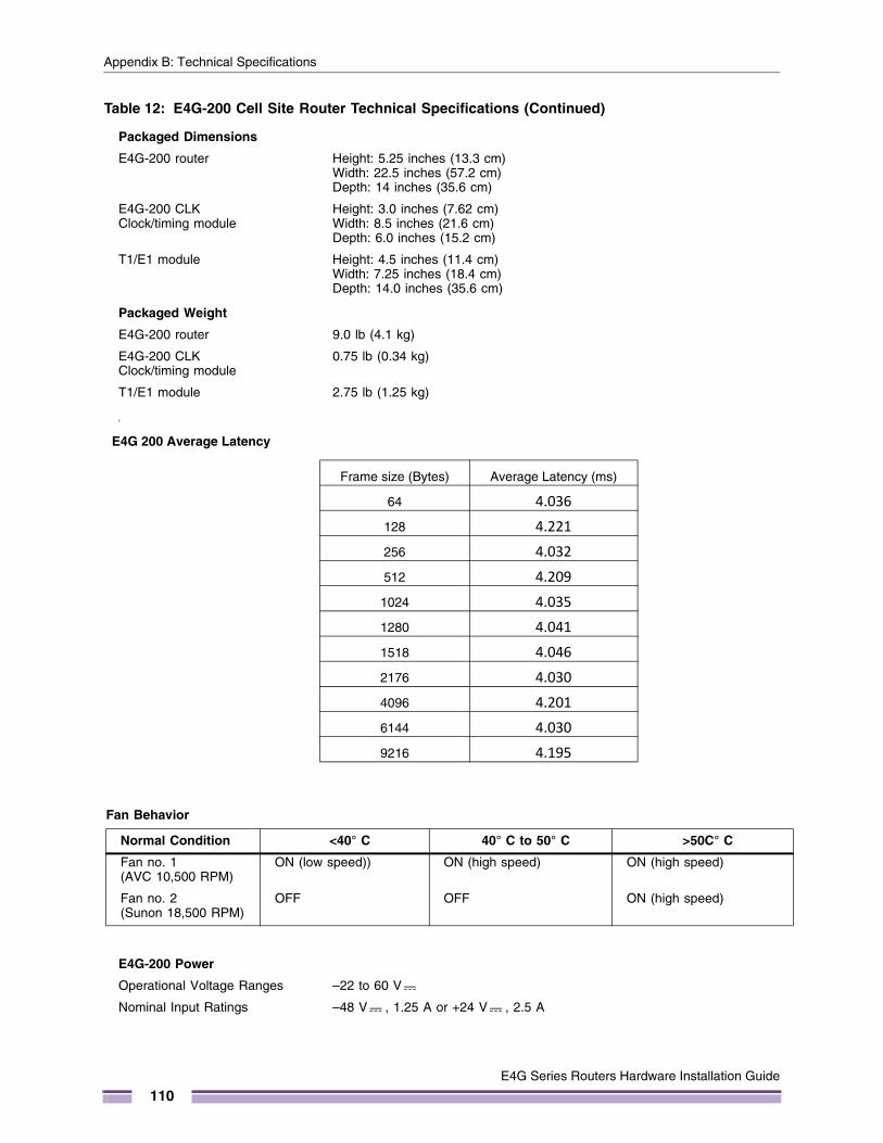
Appendix B: Technical Specifications
Packaged Dimensions
E4G-200 router Height: 5.25 inches (13.3 cm)Width: 22.5 inches (57.2 cm)Depth: 14 inches (35.6 cm)
E4G-200 CLK Clock/timing module
Height: 3.0 inches (7.62 cm)Width: 8.5 inches (21.6 cm)Depth: 6.0 inches (15.2 cm)
T1/E1 module Height: 4.5 inches (11.4 cm)Width: 7.25 inches (18.4 cm)Depth: 14.0 inches (35.6 cm)
Packaged Weight
E4G-200 router 9.0 lb (4.1 kg)
E4G-200 CLK Clock/timing module
0.75 lb (0.34 kg)
T1/E1 module 2.75 lb (1.25 kg)
y
E4G-200 Power
Operational Voltage Ranges –22 to 60 V
Nominal Input Ratings –48 V , 1.25 A or +24 V , 2.5 A
Table 12: E4G-200 Cell Site Router Technical Specifications (Continued)
E4G 200 Average Latency
Frame size (Bytes) Average Latency (ms)
64 4.036
128 4.221
256 4.032
512 4.209
1024 4.035
1280 4.041
1518 4.046
2176 4.030
4096 4.201
6144 4.030
9216 4.195
Fan Behavior
Normal Condition <40° C 40° C to 50° C >50C° C
Fan no. 1 (AVC 10,500 RPM)
ON (low speed)) ON (high speed) ON (high speed)
Fan no. 2 (Sunon 18,500 RPM)
OFF OFF ON (high speed)
E4G Series Routers Hardware Installation Guide
110
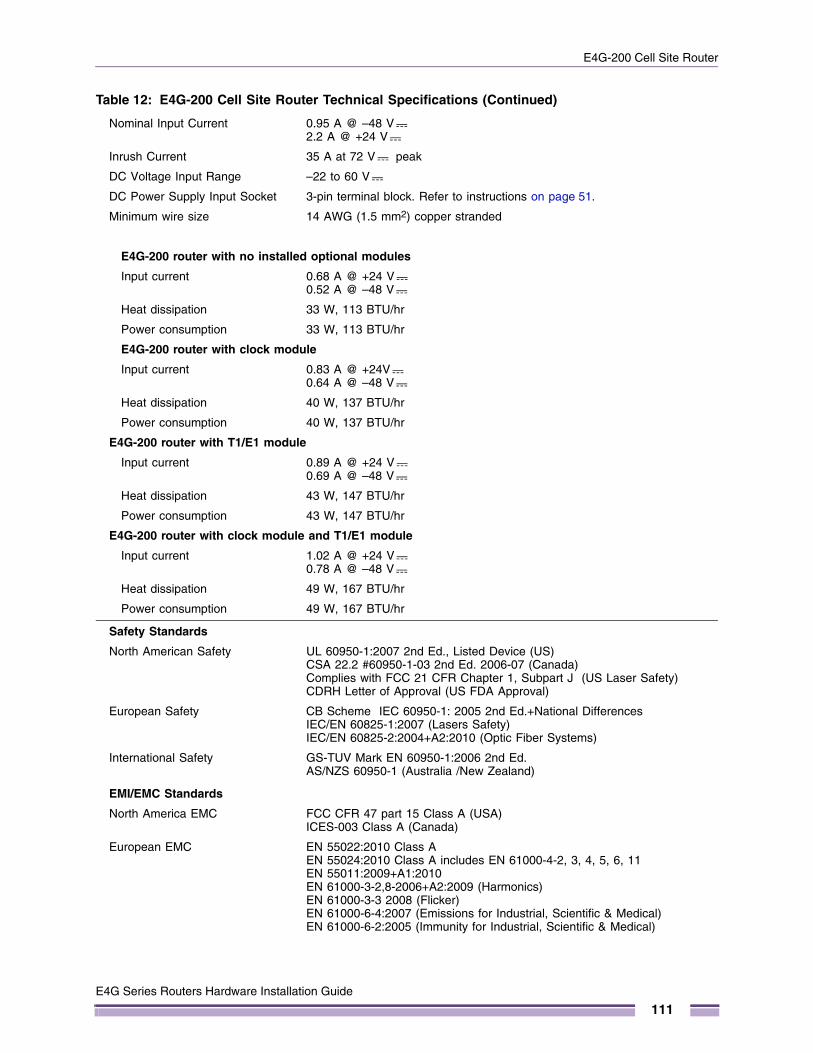
E4G-200 Cell Site Router
Nominal Input Current 0.95 A @ –48 V2.2 A @ +24 V
Inrush Current 35 A at 72 V peak
DC Voltage Input Range –22 to 60 V
DC Power Supply Input Socket 3-pin terminal block. Refer to instructions on page 51.
Minimum wire size 14 AWG (1.5 mm2) copper stranded
E4G-200 router with no installed optional modules
Input current 0.68 A @ +24 V 0.52 A @ –48 V
Heat dissipation 33 W, 113 BTU/hr
Power consumption 33 W, 113 BTU/hr
E4G-200 router with clock module
Input current 0.83 A @ +24V 0.64 A @ –48 V
Heat dissipation 40 W, 137 BTU/hr
Power consumption 40 W, 137 BTU/hr
E4G-200 router with T1/E1 module
Input current 0.89 A @ +24 V 0.69 A @ –48 V
Heat dissipation 43 W, 147 BTU/hr
Power consumption 43 W, 147 BTU/hr
E4G-200 router with clock module and T1/E1 module
Input current 1.02 A @ +24 V 0.78 A @ –48 V
Heat dissipation 49 W, 167 BTU/hr
Power consumption 49 W, 167 BTU/hr
Safety Standards
North American Safety UL 60950-1:2007 2nd Ed., Listed Device (US)CSA 22.2 #60950-1-03 2nd Ed. 2006-07 (Canada)Complies with FCC 21 CFR Chapter 1, Subpart J (US Laser Safety)CDRH Letter of Approval (US FDA Approval)
European Safety CB Scheme IEC 60950-1: 2005 2nd Ed.+National Differences IEC/EN 60825-1:2007 (Lasers Safety)IEC/EN 60825-2:2004+A2:2010 (Optic Fiber Systems)
International Safety GS-TUV Mark EN 60950-1:2006 2nd Ed.AS/NZS 60950-1 (Australia /New Zealand)
EMI/EMC Standards
North America EMC FCC CFR 47 part 15 Class A (USA)ICES-003 Class A (Canada)
European EMC EN 55022:2010 Class AEN 55024:2010 Class A includes EN 61000-4-2, 3, 4, 5, 6, 11EN 55011:2009+A1:2010EN 61000-3-2,8-2006+A2:2009 (Harmonics)EN 61000-3-3 2008 (Flicker)EN 61000-6-4:2007 (Emissions for Industrial, Scientific & Medical)EN 61000-6-2:2005 (Immunity for Industrial, Scientific & Medical)
Table 12: E4G-200 Cell Site Router Technical Specifications (Continued)
E4G Series Routers Hardware Installation Guide
111
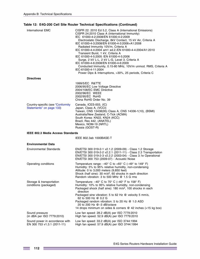
Appendix B: Technical Specifications
International EMC CISPR 22: 2010 Ed 5.2, Class A (International Emissions)CISPR 24:2010 Class A (International Immunity)IEC 61000-4-2:2008/EN 61000-4-2:2009
Electrostatic Discharge, 8kV Contact, 15 kV Air, Criteria AIEC 61000-4-3:2008/EN 61000-4-3:2006+A1:2008
Radiated Immunity 10V/m, Criteria AIEC 61000-4-4:2004 am1 ed.2./EN 61000-4-4:2004/A1:2010
Transient Burst, 1 kV, Criteria AIEC 61000-4-5:2005 /EN 61000-4-5:2006
Surge, 2 kV L-L, 2 kV L-G, Level 3, Criteria AIEC 61000-4-6:2008/EN 61000-4-6:2009
Conducted Immunity, 0.15-80 MHz, 10V/m unmod. RMS, Criteria AIEC-61000-4-11:2004
Power Dips & Interruptions, >30%, 25 periods, Criteria C
Directives
1999/5/EC R&TTE2006/95/EC Low Voltage Directive2004/108/EC EMC Directive2002/96/EC WEEE2002/95/EC RoHSChina RoHS Order No. 39
Country-specific (see “Conformity Statements” on page 133)
Canada, ICES-003, (IC) Japan, Class A, (VCCI)Taiwan, CNS 13438(95) Class A, CNS 14336-1(10), (BSMI)Australia/New Zealand, C-Tick (ACMA)South Korea: KN22, KN24 (KCC)Brazil, Res 442, (ANATEL)Mexico, NOM-19 (NRTL)Russia (GOST-R)
IEEE 802.3 Media Access Standards
IEEE 802.3ab 1000BASE-T
Environmental Data
Environmental Standards EN/ETSI 300 019-2-1 v2.1.2 (2009-09) - Class 1.2 StorageEN/ETSI 300 019-2-2 v2.2.1 (2011-11) - Class 2.3 TransportationEN/ETSI 300 019-2-3 v2.2.2 (2003-04) - Class 3.1e OperationalEN/ETSI 300 753 (2009-07) - Acoustic Noise
Operating conditions Temperature range: –40° C to +65° C (–49° to 149° F) Humidity: 5% to 95% relative humidity, non-condensing Altitude: 0 to 3,000 meters (9,850 feet)Shock (half sine): 30 m/s2, 60 shocks in each directionRandom vibration: 3 to 500 MHz @ 1.5 G rms
Storage & transportation conditions (packaged)
Temperature: –40° C to 70° C (–40° F to 158° F) Humidity: 10% to 95% relative humidity, non-condensingPackaged shock (half sine): 180 m/s2, 100 shocks in each
directionPackaged sine vibration: 5 to 62 Hz @ velocity 5 mm/s,
62 to 500 Hz @ 0.2 G Packaged random vibration: 5 to 20 Hz @ 1.0 ASD
20 to 200 Hz @–3 dB/octave 14 drops minimum on sides & corners @ 42 inches (<15 kg box)
Sound pressure(in dBA per ISO 7779:2010)
Low fan speed: 28.2 dB(A) per ISO 7779:2010High fan speed: 52.9 dB(A) per ISO 7779:2010
Sound power in accordance with EN 300 753 v1.3.1 (2011-11)
Low fan speed: 33.2 dB(A) per ISO 3744:1994High fan speed: 57.9 dB(A) per ISO 3744:1994
Table 12: E4G-200 Cell Site Router Technical Specifications (Continued)
E4G Series Routers Hardware Installation Guide
112
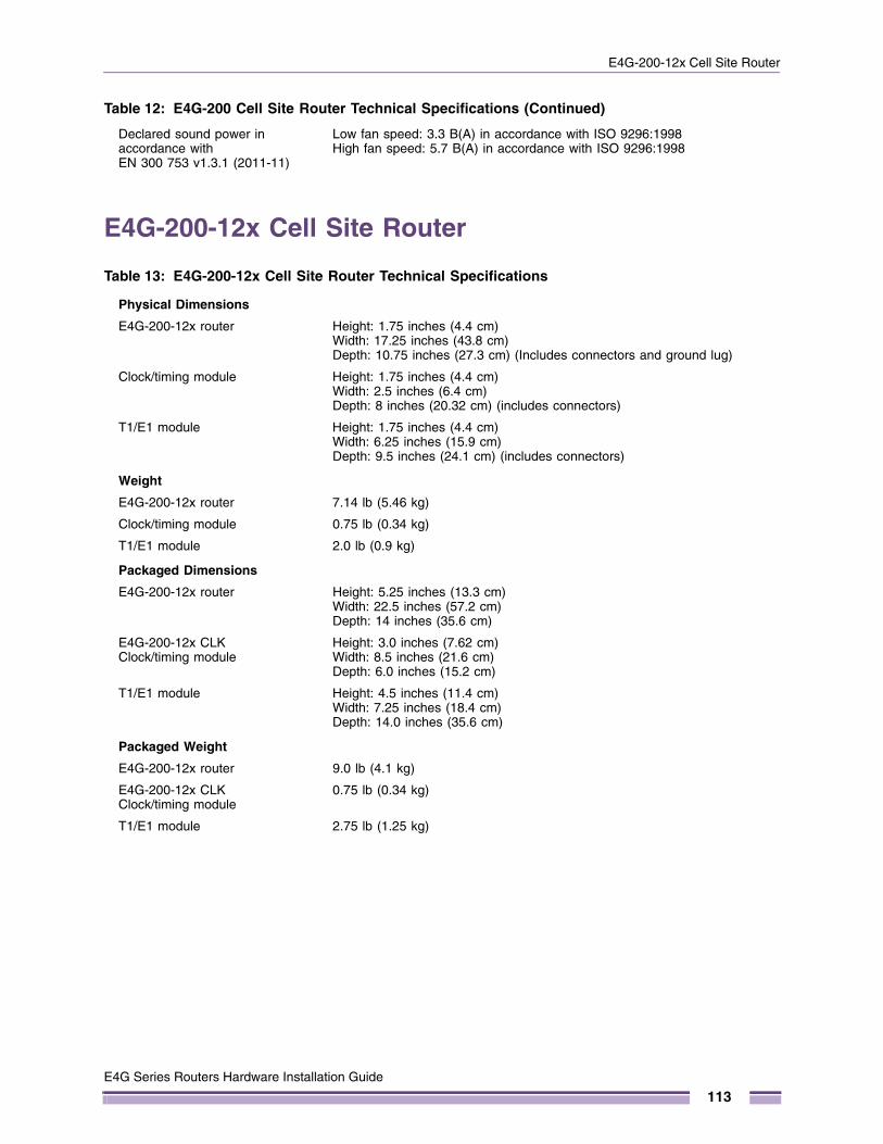
E4G-200-12x Cell Site Router
E4G-200-12x Cell Site Router
Declared sound power in accordance with EN 300 753 v1.3.1 (2011-11)
Low fan speed: 3.3 B(A) in accordance with ISO 9296:1998High fan speed: 5.7 B(A) in accordance with ISO 9296:1998
Table 13: E4G-200-12x Cell Site Router Technical Specifications
Physical Dimensions
E4G-200-12x router Height: 1.75 inches (4.4 cm)Width: 17.25 inches (43.8 cm)Depth: 10.75 inches (27.3 cm) (Includes connectors and ground lug)
Clock/timing module Height: 1.75 inches (4.4 cm)Width: 2.5 inches (6.4 cm)Depth: 8 inches (20.32 cm) (includes connectors)
T1/E1 module Height: 1.75 inches (4.4 cm)Width: 6.25 inches (15.9 cm)Depth: 9.5 inches (24.1 cm) (includes connectors)
Weight
E4G-200-12x router 7.14 lb (5.46 kg)
Clock/timing module 0.75 lb (0.34 kg)
T1/E1 module 2.0 lb (0.9 kg)
Packaged Dimensions
E4G-200-12x router Height: 5.25 inches (13.3 cm)Width: 22.5 inches (57.2 cm)Depth: 14 inches (35.6 cm)
E4G-200-12x CLK Clock/timing module
Height: 3.0 inches (7.62 cm)Width: 8.5 inches (21.6 cm)Depth: 6.0 inches (15.2 cm)
T1/E1 module Height: 4.5 inches (11.4 cm)Width: 7.25 inches (18.4 cm)Depth: 14.0 inches (35.6 cm)
Packaged Weight
E4G-200-12x router 9.0 lb (4.1 kg)
E4G-200-12x CLK Clock/timing module
0.75 lb (0.34 kg)
T1/E1 module 2.75 lb (1.25 kg)
Table 12: E4G-200 Cell Site Router Technical Specifications (Continued)
E4G Series Routers Hardware Installation Guide
113
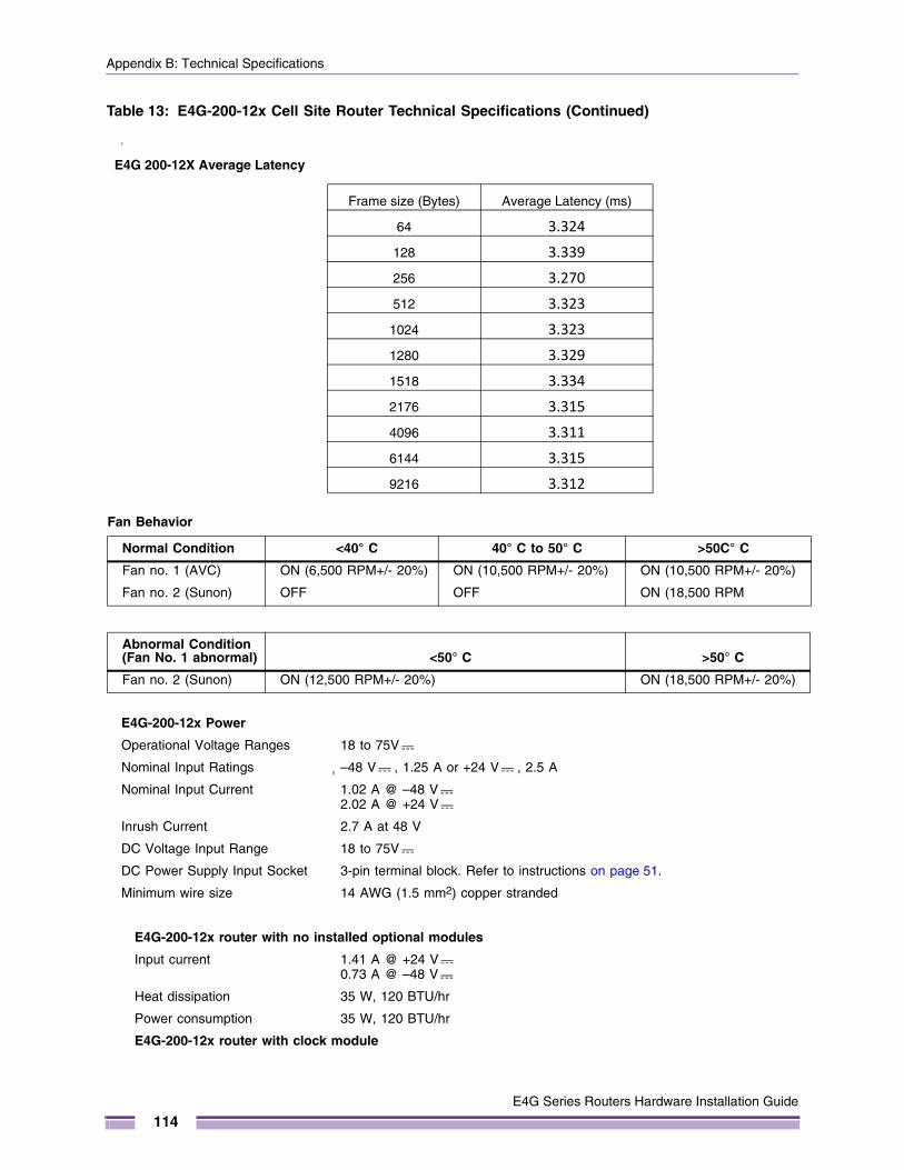
Appendix B: Technical Specifications
y
E4G-200-12x Power
Operational Voltage Ranges 18 to 75V
Nominal Input Ratings –48 V , 1.25 A or +24 V , 2.5 A
Nominal Input Current 1.02 A @ –48 V2.02 A @ +24 V
Inrush Current 2.7 A at 48 V
DC Voltage Input Range 18 to 75V
DC Power Supply Input Socket 3-pin terminal block. Refer to instructions on page 51.
Minimum wire size 14 AWG (1.5 mm2) copper stranded
E4G-200-12x router with no installed optional modules
Input current 1.41 A @ +24 V 0.73 A @ –48 V
Heat dissipation 35 W, 120 BTU/hr
Power consumption 35 W, 120 BTU/hr
E4G-200-12x router with clock module
Table 13: E4G-200-12x Cell Site Router Technical Specifications (Continued)
E4G 200-12X Average Latency
Frame size (Bytes) Average Latency (ms)
64 3.324
128 3.339
256 3.270
512 3.323
1024 3.323
1280 3.329
1518 3.334
2176 3.315
4096 3.311
6144 3.315
9216 3.312
Fan Behavior
Normal Condition <40° C 40° C to 50° C >50C° C
Fan no. 1 (AVC) ON (6,500 RPM+/- 20%) ON (10,500 RPM+/- 20%) ON (10,500 RPM+/- 20%)
Fan no. 2 (Sunon) OFF OFF ON (18,500 RPM
Abnormal Condition(Fan No. 1 abnormal) <50° C >50° C
Fan no. 2 (Sunon) ON (12,500 RPM+/- 20%) ON (18,500 RPM+/- 20%)
E4G Series Routers Hardware Installation Guide
114
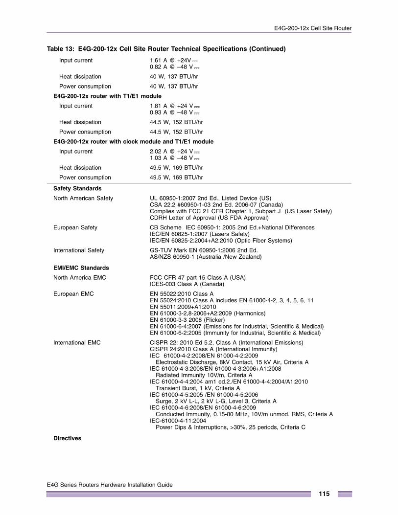
E4G-200-12x Cell Site Router
Input current 1.61 A @ +24V 0.82 A @ –48 V
Heat dissipation 40 W, 137 BTU/hr
Power consumption 40 W, 137 BTU/hr
E4G-200-12x router with T1/E1 module
Input current 1.81 A @ +24 V 0.93 A @ –48 V
Heat dissipation 44.5 W, 152 BTU/hr
Power consumption 44.5 W, 152 BTU/hr
E4G-200-12x router with clock module and T1/E1 module
Input current 2.02 A @ +24 V 1.03 A @ –48 V
Heat dissipation 49.5 W, 169 BTU/hr
Power consumption 49.5 W, 169 BTU/hr
Safety Standards
North American Safety UL 60950-1:2007 2nd Ed., Listed Device (US)CSA 22.2 #60950-1-03 2nd Ed. 2006-07 (Canada)Complies with FCC 21 CFR Chapter 1, Subpart J (US Laser Safety)CDRH Letter of Approval (US FDA Approval)
European Safety CB Scheme IEC 60950-1: 2005 2nd Ed.+National Differences IEC/EN 60825-1:2007 (Lasers Safety)IEC/EN 60825-2:2004+A2:2010 (Optic Fiber Systems)
International Safety GS-TUV Mark EN 60950-1:2006 2nd Ed.AS/NZS 60950-1 (Australia /New Zealand)
EMI/EMC Standards
North America EMC FCC CFR 47 part 15 Class A (USA)ICES-003 Class A (Canada)
European EMC EN 55022:2010 Class AEN 55024:2010 Class A includes EN 61000-4-2, 3, 4, 5, 6, 11EN 55011:2009+A1:2010EN 61000-3-2,8-2006+A2:2009 (Harmonics)EN 61000-3-3 2008 (Flicker)EN 61000-6-4:2007 (Emissions for Industrial, Scientific & Medical)EN 61000-6-2:2005 (Immunity for Industrial, Scientific & Medical)
International EMC CISPR 22: 2010 Ed 5.2, Class A (International Emissions)CISPR 24:2010 Class A (International Immunity)IEC 61000-4-2:2008/EN 61000-4-2:2009
Electrostatic Discharge, 8kV Contact, 15 kV Air, Criteria AIEC 61000-4-3:2008/EN 61000-4-3:2006+A1:2008
Radiated Immunity 10V/m, Criteria AIEC 61000-4-4:2004 am1 ed.2./EN 61000-4-4:2004/A1:2010
Transient Burst, 1 kV, Criteria AIEC 61000-4-5:2005 /EN 61000-4-5:2006
Surge, 2 kV L-L, 2 kV L-G, Level 3, Criteria AIEC 61000-4-6:2008/EN 61000-4-6:2009
Conducted Immunity, 0.15-80 MHz, 10V/m unmod. RMS, Criteria AIEC-61000-4-11:2004
Power Dips & Interruptions, >30%, 25 periods, Criteria C
Directives
Table 13: E4G-200-12x Cell Site Router Technical Specifications (Continued)
E4G Series Routers Hardware Installation Guide
115
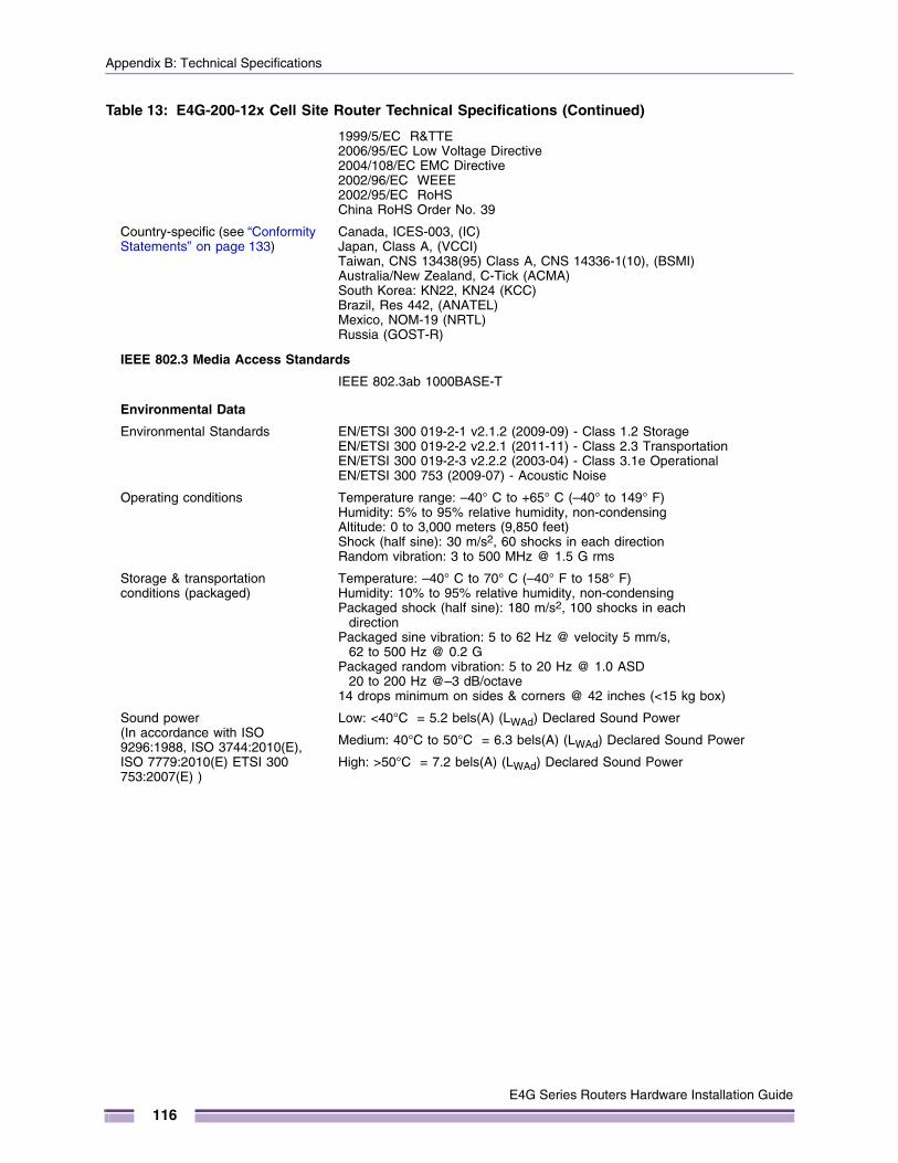
Appendix B: Technical Specifications
1999/5/EC R&TTE2006/95/EC Low Voltage Directive2004/108/EC EMC Directive2002/96/EC WEEE2002/95/EC RoHSChina RoHS Order No. 39
Country-specific (see “Conformity Statements” on page 133)
Canada, ICES-003, (IC) Japan, Class A, (VCCI)Taiwan, CNS 13438(95) Class A, CNS 14336-1(10), (BSMI)Australia/New Zealand, C-Tick (ACMA)South Korea: KN22, KN24 (KCC)Brazil, Res 442, (ANATEL)Mexico, NOM-19 (NRTL)Russia (GOST-R)
IEEE 802.3 Media Access Standards
IEEE 802.3ab 1000BASE-T
Environmental Data
Environmental Standards EN/ETSI 300 019-2-1 v2.1.2 (2009-09) - Class 1.2 StorageEN/ETSI 300 019-2-2 v2.2.1 (2011-11) - Class 2.3 TransportationEN/ETSI 300 019-2-3 v2.2.2 (2003-04) - Class 3.1e OperationalEN/ETSI 300 753 (2009-07) - Acoustic Noise
Operating conditions Temperature range: –40° C to +65° C (–40° to 149° F) Humidity: 5% to 95% relative humidity, non-condensing Altitude: 0 to 3,000 meters (9,850 feet)Shock (half sine): 30 m/s2, 60 shocks in each directionRandom vibration: 3 to 500 MHz @ 1.5 G rms
Storage & transportation conditions (packaged)
Temperature: –40° C to 70° C (–40° F to 158° F) Humidity: 10% to 95% relative humidity, non-condensingPackaged shock (half sine): 180 m/s2, 100 shocks in each
directionPackaged sine vibration: 5 to 62 Hz @ velocity 5 mm/s,
62 to 500 Hz @ 0.2 G Packaged random vibration: 5 to 20 Hz @ 1.0 ASD
20 to 200 Hz @–3 dB/octave 14 drops minimum on sides & corners @ 42 inches (<15 kg box)
Sound power(In accordance with ISO 9296:1988, ISO 3744:2010(E), ISO 7779:2010(E) ETSI 300 753:2007(E) )
Low: <40°C = 5.2 bels(A) (LWAd) Declared Sound Power
Medium: 40°C to 50°C = 6.3 bels(A) (LWAd) Declared Sound Power
High: >50°C = 7.2 bels(A) (LWAd) Declared Sound Power
Table 13: E4G-200-12x Cell Site Router Technical Specifications (Continued)
E4G Series Routers Hardware Installation Guide
116
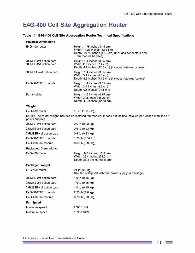
E4G-400 Cell Site Aggregation Router
E4G-400 Cell Site Aggregation Router
Table 14: E4G-400 Cell Site Aggregation Router Technical Specifications
Physical Dimensions
E4G-400 router Height: 1.75 inches (4.4 cm)Width: 17.25 inches (43.8 cm)Depth: 18.75 inches (43.2 cm) (Includes connectors and
fan module handles)
XGM3S-2sf option cardXGM3S-2xf option card
Height: 1.4 inches (3.55 cm)Width: 2.9 inches (7.4 cm)Depth: 4.9 inches (12.5 cm) (includes retaining screws)
XGM3SB-4sf option card Height: 1.4 inches (3.55 cm)Width: 3.4 inches (8.6 cm)Depth: 5.5 inches (13.9 cm) (includes retaining screws)
E4G-B16T1E1 module Height: 1.4 inches (3.55 cm)Width: 3.4 inches (8.6 cm)Depth: 9.5 inches (24.1 cm)
Fan module Height: 1.6 inches (4.15 cm)Width: 3.25 inches (8.26 cm)Depth: 4.9 inches (12.53 cm)
Weight
E4G-400 router 13.75 lb (6.2 kg)
NOTE: The router weight includes an installed fan module. It does not include installed port option modules or power supplies.
XGM3S-2sf option card 0.5 lb (0.23 kg)
XGM3S-2xf option card 0.5 lb (0.23 kg)
XGM3SB-4sf option card 0.5 lb (0.23 kg)
E4G-B16T1E1 module 1.25 lb (0.57 kg)
E4G-400 fan module 0.66 lb (0.30 kg)
Packaged Dimensions
E4G-400 router Height: 6.5 inches (16.5 cm)Width: 23.4 inches (59.3 cm)Depth: 26.2 inches (66.5 cm)
Packaged Weight
E4G-400 router 21 lb (9.5 kg)(Router is shipped with one power supply in package)
XGM3S-2sf option card 1.0 lb (0.45 kg)
XGM3S-2xf option card 1.0 lb (0.45 kg)
XGM3SB-4sf option card 1.0 lb (0.45 kg)
E4G-B16T1E1 module 2.25 lb (1.0 kg)
E4G-400 fan module 0.79 lb (0.36 kg)
Fan Speed
Minimum speed 2500 RPM
Maximum speed 15900 RPM
E4G Series Routers Hardware Installation Guide
117
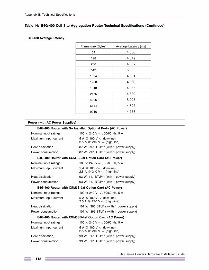
Appendix B: Technical Specifications
y
Power (with AC Power Supplies)
E4G-400 Router with No Installed Optional Ports (AC Power)
Nominal input ratings 100 to 240 V , 50/60 Hz, 5 A
Maximum Input current 5 A @ 100 V (low-line)2.5 A @ 240 V (high-line)
Heat dissipation 87 W, 297 BTU/hr (with 1 power supply)
Power consumption 87 W, 297 BTU/hr (with 1 power supply)
E4G-400 Router with XGM3S-2sf Option Card (AC Power)
Nominal input ratings 100 to 240 V , 50/60 Hz, 5 A
Maximum Input current 5 A @ 100 V (low-line)2.5 A @ 240 V (high-line)
Heat dissipation 93 W, 317 BTU/hr (with 1 power supply)
Power consumption 93 W, 317 BTU/hr (with 1 power supply)
E4G-400 Router with XGM3S-2xf Option Card (AC Power)
Nominal input ratings 100 to 240 V , 50/60 Hz, 5 A
Maximum Input current 5 A @ 100 V (low-line)2.5 A @ 240 V (high-line)
Heat dissipation 107 W, 365 BTU/hr (with 1 power supply)
Power consumption 107 W, 365 BTU/hr (with 1 power supply)
E4G-400 Router with XGM3SB-4sf Option Card (AC Power)
Nominal input ratings 100 to 240 V , 50/60 Hz, 5 A
Maximum Input current 5 A @ 100 V (low-line)2.5 A @ 240 V (high-line)
Heat dissipation, 93 W, 317 BTU/hr (with 1 power supply)
Power consumption 93 W, 317 BTU/hr (with 1 power supply)
Table 14: E4G-400 Cell Site Aggregation Router Technical Specifications (Continued)
E4G-400 Average Latency
Frame size (Bytes) Average Latency (ms)
64 4.330
128 4.542
256 4.897
512 5.055
1024 4.891
1280 4.980
1518 4.955
2176 4.889
4096 5.023
6144 4.892
9216 4.967
E4G Series Routers Hardware Installation Guide
118
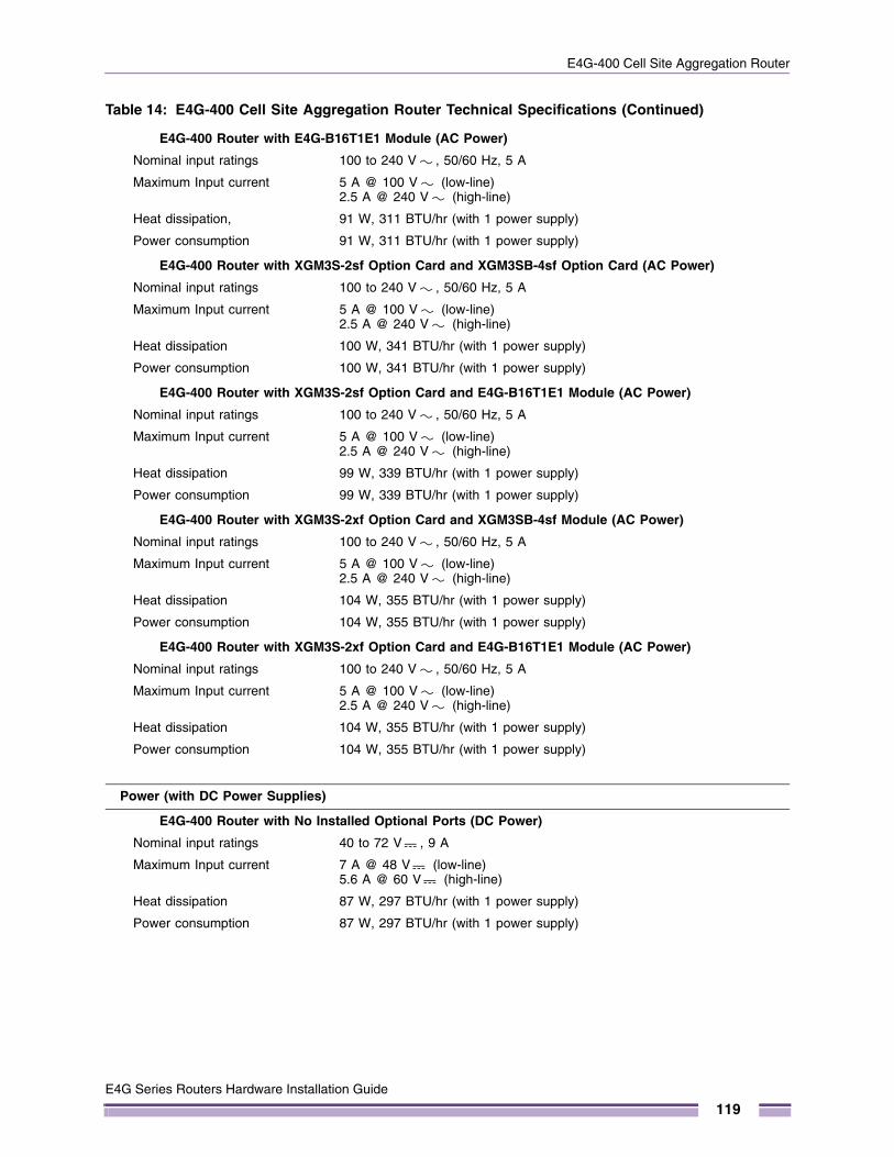
E4G-400 Cell Site Aggregation Router
E4G-400 Router with E4G-B16T1E1 Module (AC Power)
Nominal input ratings 100 to 240 V , 50/60 Hz, 5 A
Maximum Input current 5 A @ 100 V (low-line)2.5 A @ 240 V (high-line)
Heat dissipation, 91 W, 311 BTU/hr (with 1 power supply)
Power consumption 91 W, 311 BTU/hr (with 1 power supply)
E4G-400 Router with XGM3S-2sf Option Card and XGM3SB-4sf Option Card (AC Power)
Nominal input ratings 100 to 240 V , 50/60 Hz, 5 A
Maximum Input current 5 A @ 100 V (low-line)2.5 A @ 240 V (high-line)
Heat dissipation 100 W, 341 BTU/hr (with 1 power supply)
Power consumption 100 W, 341 BTU/hr (with 1 power supply)
E4G-400 Router with XGM3S-2sf Option Card and E4G-B16T1E1 Module (AC Power)
Nominal input ratings 100 to 240 V , 50/60 Hz, 5 A
Maximum Input current 5 A @ 100 V (low-line)2.5 A @ 240 V (high-line)
Heat dissipation 99 W, 339 BTU/hr (with 1 power supply)
Power consumption 99 W, 339 BTU/hr (with 1 power supply)
E4G-400 Router with XGM3S-2xf Option Card and XGM3SB-4sf Module (AC Power)
Nominal input ratings 100 to 240 V , 50/60 Hz, 5 A
Maximum Input current 5 A @ 100 V (low-line)2.5 A @ 240 V (high-line)
Heat dissipation 104 W, 355 BTU/hr (with 1 power supply)
Power consumption 104 W, 355 BTU/hr (with 1 power supply)
E4G-400 Router with XGM3S-2xf Option Card and E4G-B16T1E1 Module (AC Power)
Nominal input ratings 100 to 240 V , 50/60 Hz, 5 A
Maximum Input current 5 A @ 100 V (low-line)2.5 A @ 240 V (high-line)
Heat dissipation 104 W, 355 BTU/hr (with 1 power supply)
Power consumption 104 W, 355 BTU/hr (with 1 power supply)
Power (with DC Power Supplies)
E4G-400 Router with No Installed Optional Ports (DC Power)
Nominal input ratings 40 to 72 V , 9 A
Maximum Input current 7 A @ 48 V (low-line)5.6 A @ 60 V (high-line)
Heat dissipation 87 W, 297 BTU/hr (with 1 power supply)
Power consumption 87 W, 297 BTU/hr (with 1 power supply)
Table 14: E4G-400 Cell Site Aggregation Router Technical Specifications (Continued)
E4G Series Routers Hardware Installation Guide
119
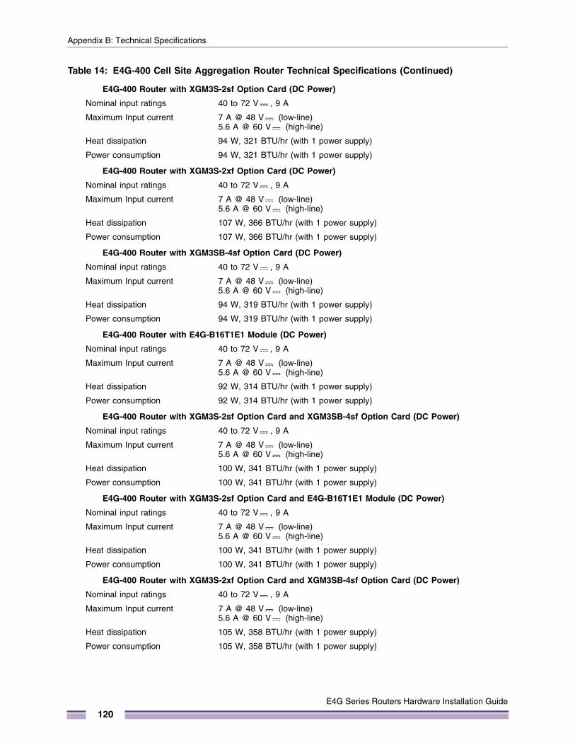
Appendix B: Technical Specifications
E4G-400 Router with XGM3S-2sf Option Card (DC Power)
Nominal input ratings 40 to 72 V , 9 A
Maximum Input current 7 A @ 48 V (low-line)5.6 A @ 60 V (high-line)
Heat dissipation 94 W, 321 BTU/hr (with 1 power supply)
Power consumption 94 W, 321 BTU/hr (with 1 power supply)
E4G-400 Router with XGM3S-2xf Option Card (DC Power)
Nominal input ratings 40 to 72 V , 9 A
Maximum Input current 7 A @ 48 V (low-line)5.6 A @ 60 V (high-line)
Heat dissipation 107 W, 366 BTU/hr (with 1 power supply)
Power consumption 107 W, 366 BTU/hr (with 1 power supply)
E4G-400 Router with XGM3SB-4sf Option Card (DC Power)
Nominal input ratings 40 to 72 V , 9 A
Maximum Input current 7 A @ 48 V (low-line)5.6 A @ 60 V (high-line)
Heat dissipation 94 W, 319 BTU/hr (with 1 power supply)
Power consumption 94 W, 319 BTU/hr (with 1 power supply)
E4G-400 Router with E4G-B16T1E1 Module (DC Power)
Nominal input ratings 40 to 72 V , 9 A
Maximum Input current 7 A @ 48 V (low-line)5.6 A @ 60 V (high-line)
Heat dissipation 92 W, 314 BTU/hr (with 1 power supply)
Power consumption 92 W, 314 BTU/hr (with 1 power supply)
E4G-400 Router with XGM3S-2sf Option Card and XGM3SB-4sf Option Card (DC Power)
Nominal input ratings 40 to 72 V , 9 A
Maximum Input current 7 A @ 48 V (low-line)5.6 A @ 60 V (high-line)
Heat dissipation 100 W, 341 BTU/hr (with 1 power supply)
Power consumption 100 W, 341 BTU/hr (with 1 power supply)
E4G-400 Router with XGM3S-2sf Option Card and E4G-B16T1E1 Module (DC Power)
Nominal input ratings 40 to 72 V , 9 A
Maximum Input current 7 A @ 48 V (low-line)5.6 A @ 60 V (high-line)
Heat dissipation 100 W, 341 BTU/hr (with 1 power supply)
Power consumption 100 W, 341 BTU/hr (with 1 power supply)
E4G-400 Router with XGM3S-2xf Option Card and XGM3SB-4sf Option Card (DC Power)
Nominal input ratings 40 to 72 V , 9 A
Maximum Input current 7 A @ 48 V (low-line)5.6 A @ 60 V (high-line)
Heat dissipation 105 W, 358 BTU/hr (with 1 power supply)
Power consumption 105 W, 358 BTU/hr (with 1 power supply)
Table 14: E4G-400 Cell Site Aggregation Router Technical Specifications (Continued)
E4G Series Routers Hardware Installation Guide
120
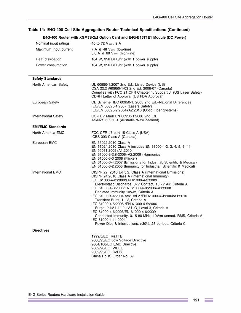
E4G-400 Cell Site Aggregation Router
E4G-400 Router with XGM3S-2xf Option Card and E4G-B16T1E1 Module (DC Power)
Nominal input ratings 40 to 72 V , 9 A
Maximum Input current 7 A @ 48 V (low-line)5.6 A @ 60 V (high-line)
Heat dissipation 104 W, 356 BTU/hr (with 1 power supply)
Power consumption 104 W, 356 BTU/hr (with 1 power supply)
Safety Standards
North American Safety UL 60950-1:2007 2nd Ed., Listed Device (US)CSA 22.2 #60950-1-03 2nd Ed. 2006-07 (Canada)Complies with FCC 21 CFR Chapter 1, Subpart J (US Laser Safety)CDRH Letter of Approval (US FDA Approval)
European Safety CB Scheme IEC 60950-1: 2005 2nd Ed.+National Differences IEC/EN 60825-1:2007 (Lasers Safety)IEC/EN 60825-2:2004+A2:2010 (Optic Fiber Systems)
International Safety GS-TUV Mark EN 60950-1:2006 2nd Ed.AS/NZS 60950-1 (Australia /New Zealand)
EMI/EMC Standards
North America EMC FCC CFR 47 part 15 Class A (USA)ICES-003 Class A (Canada)
European EMC EN 55022:2010 Class AEN 55024:2010 Class A includes EN 61000-4-2, 3, 4, 5, 6, 11EN 55011:2009+A1:2010EN 61000-3-2,8-2006+A2:2009 (Harmonics)EN 61000-3-3 2008 (Flicker)EN 61000-6-4:2007 (Emissions for Industrial, Scientific & Medical)EN 61000-6-2:2005 (Immunity for Industrial, Scientific & Medical)
International EMC CISPR 22: 2010 Ed 5.2, Class A (International Emissions)CISPR 24:2010 Class A (International Immunity)IEC 61000-4-2:2008/EN 61000-4-2:2009
Electrostatic Discharge, 8kV Contact, 15 kV Air, Criteria AIEC 61000-4-3:2008/EN 61000-4-3:2006+A1:2008
Radiated Immunity 10V/m, Criteria AIEC 61000-4-4:2004 am1 ed.2./EN 61000-4-4:2004/A1:2010
Transient Burst, 1 kV, Criteria AIEC 61000-4-5:2005 /EN 61000-4-5:2006
Surge, 2 kV L-L, 2 kV L-G, Level 3, Criteria AIEC 61000-4-6:2008/EN 61000-4-6:2009
Conducted Immunity, 0.15-80 MHz, 10V/m unmod. RMS, Criteria AIEC-61000-4-11:2004
Power Dips & Interruptions, >30%, 25 periods, Criteria C
Directives
1999/5/EC R&TTE2006/95/EC Low Voltage Directive2004/108/EC EMC Directive2002/96/EC WEEE2002/95/EC RoHSChina RoHS Order No. 39
Table 14: E4G-400 Cell Site Aggregation Router Technical Specifications (Continued)
E4G Series Routers Hardware Installation Guide
121
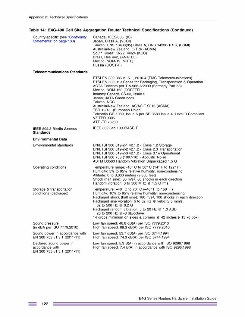
Appendix B: Technical Specifications
Country-specific (see “Conformity Statements” on page 133)
Canada, ICES-003, (IC) Japan, Class A, (VCCI)Taiwan, CNS 13438(95) Class A, CNS 14336-1(10), (BSMI)Australia/New Zealand, C-Tick (ACMA)South Korea: KN22, KN24 (KCC)Brazil, Res 442, (ANATEL)Mexico, NOM-19 (NRTL)Russia (GOST-R)
Telecommunications Standards
ETSI EN 300 386 v1.5.1, 2010-4 (EMC Telecommunications)ETSI EN 300 019 Series for Packaging, Transportation & Operation ACTA Telecom per TIA-968-A:2009 (Formerly Part 68)Mexico, NOM-152 (COFETEL)Industry Canada CS-03, Issue 9Japan, JATA Green bookTaiwan, NCCAustralia/New Zealand, AS/ACIF S016 (ACMA)TBR 12/13 (European Union)Telcordia GR-1089, Issue 6 per SR 3580 issue 4, Level 3 CompliantVZ.TPR.9305ATT.-TP.76200
IEEE 802.3 Media Access Standards
IEEE 802.3ab 1000BASE-T
Environmental Data
Environmental standards EN/ETSI 300 019-2-1 v2.1.2 - Class 1.2 StorageEN/ETSI 300 019-2-2 v2.1.2 - Class 2.3 TransportationEN/ETSI 300 019-2-3 v2.1.2 - Class 3.1e OperationalEN/ETSI 300 753 (1997-10) - Acoustic NoiseASTM D3580 Random Vibration Unpackaged 1.5 G
Operating conditions Temperature range: -10° C to 50° C (14° F to 122° F)Humidity: 5% to 95% relative humidity, non-condensingAltitude: 0 to 3,000 meters (9,850 feet)Shock (half sine): 30 m/s2, 60 shocks in each directionRandom vibration: 3 to 500 MHz @ 1.5 G rms
Storage & transportation conditions (packaged)
Temperature: –40° C to 70° C (–40° F to 158° F) Humidity: 10% to 95% relative humidity, non-condensingPackaged shock (half sine): 180 m/s2, 100 shocks in each directionPackaged sine vibration: 5 to 62 Hz @ velocity 5 mm/s,
62 to 500 Hz @ 0.2 G Packaged random vibration: 5 to 20 Hz @ 1.0 ASD
20 to 200 Hz @–3 dB/octave 14 drops minimum on sides & corners @ 42 inches (<15 kg box)
Sound pressure(in dBA per ISO 7779:2010)
Low fan speed: 48.8 dB(A) per ISO 7779:2010High fan speed: 69.3 dB(A) per ISO 7779:2010
Sound power in accordance with EN 300 753 v1.3.1 (2011-11)
Low fan speed: 53.7 dB(A) per ISO 3744:1994High fan speed: 74.3 dB(A) per ISO 3744:1994
Declared sound power in accordance with EN 300 753 v1.3.1 (2011-11)
Low fan speed: 5.3 B(A) in accordance with ISO 9296:1998High fan speed: 7.4 B(A) in accordance with ISO 9296:1998
Table 14: E4G-400 Cell Site Aggregation Router Technical Specifications (Continued)
E4G Series Routers Hardware Installation Guide
122
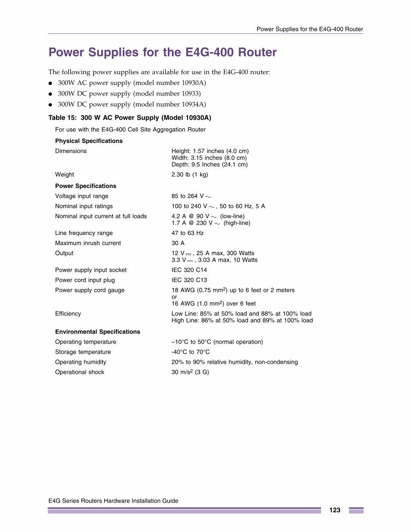
Power Supplies for the E4G-400 Router
Power Supplies for the E4G-400 RouterThe following power supplies are available for use in the E4G-400 router:
● 300W AC power supply (model number 10930A)
● 300W DC power supply (model number 10933)
● 300W DC power supply (model number 10934A)
Table 15: 300 W AC Power Supply (Model 10930A)
For use with the E4G-400 Cell Site Aggregation Router
Physical Specifications
Dimensions Height: 1.57 inches (4.0 cm)Width: 3.15 inches (8.0 cm)Depth: 9.5 Inches (24.1 cm)
Weight 2.30 lb (1 kg)
Power Specifications
Voltage input range 85 to 264 V
Nominal input ratings 100 to 240 V , 50 to 60 Hz, 5 A
Nominal input current at full loads 4.2 A @ 90 V (low-line)1.7 A @ 230 V (high-line)
Line frequency range 47 to 63 Hz
Maximum inrush current 30 A
Output 12 V , 25 A max, 300 Watts3.3 V , 3.03 A max, 10 Watts
Power supply input socket IEC 320 C14
Power cord input plug IEC 320 C13
Power supply cord gauge 18 AWG (0.75 mm2) up to 6 feet or 2 metersor16 AWG (1.0 mm2) over 6 feet
Efficiency Low Line: 85% at 50% load and 88% at 100% loadHigh Line: 86% at 50% load and 89% at 100% load
Environmental Specifications
Operating temperature –10°C to 50°C (normal operation)
Storage temperature -40°C to 70°C
Operating humidity 20% to 90% relative humidity, non-condensing
Operational shock 30 m/s2 (3 G)
E4G Series Routers Hardware Installation Guide
123
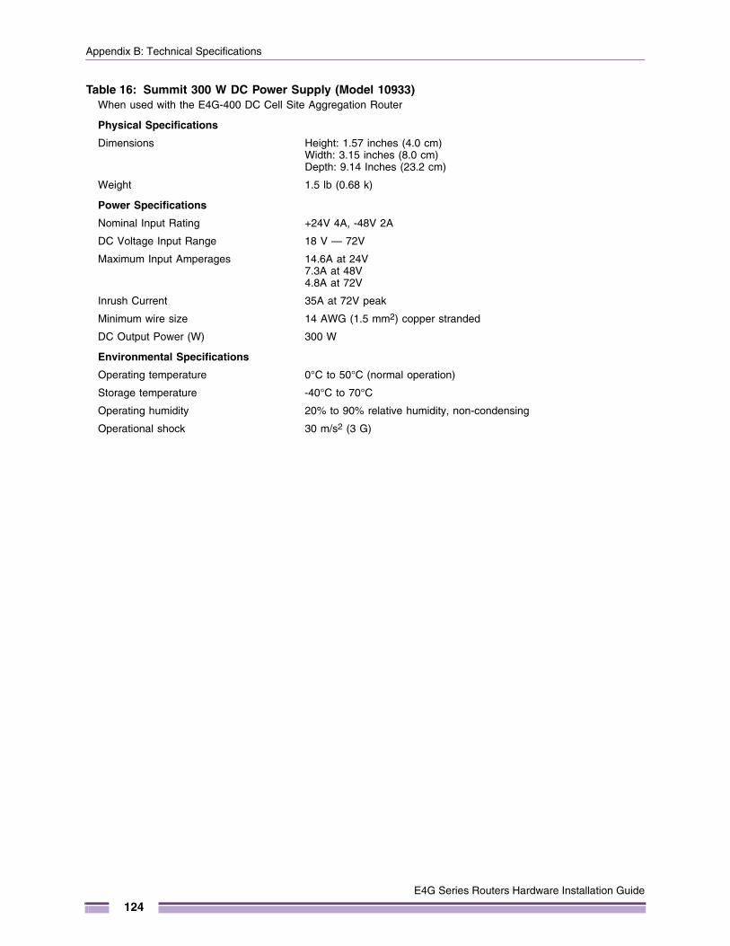
Appendix B: Technical Specifications
Table 16: Summit 300 W DC Power Supply (Model 10933)When used with the E4G-400 DC Cell Site Aggregation Router
Physical Specifications
Dimensions Height: 1.57 inches (4.0 cm)Width: 3.15 inches (8.0 cm)Depth: 9.14 Inches (23.2 cm)
Weight 1.5 lb (0.68 k)
Power Specifications
Nominal Input Rating +24V 4A, -48V 2A
DC Voltage Input Range 18 V — 72V
Maximum Input Amperages 14.6A at 24V7.3A at 48V4.8A at 72V
Inrush Current 35A at 72V peak
Minimum wire size 14 AWG (1.5 mm2) copper stranded
DC Output Power (W) 300 W
Environmental Specifications
Operating temperature 0°C to 50°C (normal operation)
Storage temperature -40°C to 70°C
Operating humidity 20% to 90% relative humidity, non-condensing
Operational shock 30 m/s2 (3 G)
E4G Series Routers Hardware Installation Guide
124
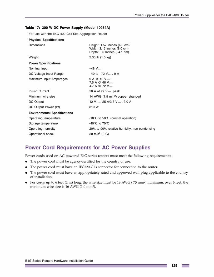
Power Supplies for the E4G-400 Router
Power Cord Requirements for AC Power SuppliesPower cords used on AC-powered E4G series routers must meet the following requirements:
● The power cord must be agency-certified for the country of use.
● The power cord must have an IEC320-C13 connector for connection to the router.
● The power cord must have an appropriately rated and approved wall plug applicable to the country of installation.
● For cords up to 6 feet (2 m) long, the wire size must be 18 AWG (.75 mm2) minimum; over 6 feet, the minimum wire size is 16 AWG (1.0 mm2).
Table 17: 300 W DC Power Supply (Model 10934A)
For use with the E4G-400 Cell Site Aggregation Router
Physical Specifications
Dimensions Height: 1.57 inches (4.0 cm)Width: 3.15 inches (8.0 cm)Depth: 9.5 Inches (24.1 cm)
Weight 2.30 lb (1.0 kg)
Power Specifications
Nominal Input –48 V
DC Voltage Input Range –40 to –72 V , 9 A
Maximum Input Amperages 9 A @ 40 V7.5 A @ 48 V4.7 A @ 72 V
Inrush Current 50 A at 72 V peak
Minimum wire size 14 AWG (1.5 mm2) copper stranded
DC Output 12 V , 25 A/3.3 V , 3.0 A
DC Output Power (W) 310 W
Environmental Specifications
Operating temperature -10°C to 50°C (normal operation)
Storage temperature -40°C to 70°C
Operating humidity 20% to 90% relative humidity, non-condensing
Operational shock 30 m/s2 (3 G)
E4G Series Routers Hardware Installation Guide
125
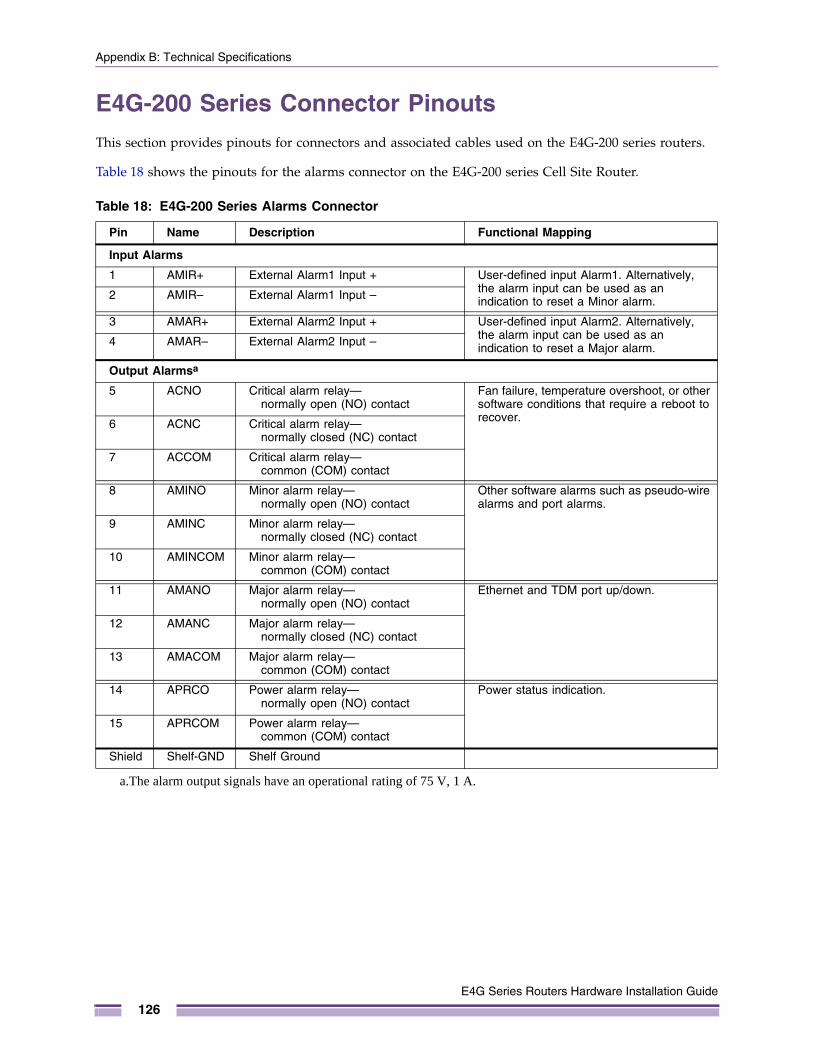
Appendix B: Technical Specifications
E4G-200 Series Connector PinoutsThis section provides pinouts for connectors and associated cables used on the E4G-200 series routers.
Table 18 shows the pinouts for the alarms connector on the E4G-200 series Cell Site Router.
Table 18: E4G-200 Series Alarms Connector
Pin Name Description Functional Mapping
Input Alarms
1 AMIR+ External Alarm1 Input + User-defined input Alarm1. Alternatively, the alarm input can be used as an indication to reset a Minor alarm.2 AMIR– External Alarm1 Input –
3 AMAR+ External Alarm2 Input + User-defined input Alarm2. Alternatively, the alarm input can be used as an indication to reset a Major alarm.4 AMAR– External Alarm2 Input –
Output Alarmsa
a.The alarm output signals have an operational rating of 75 V, 1 A.
5 ACNO Critical alarm relay—normally open (NO) contact
Fan failure, temperature overshoot, or other software conditions that require a reboot to recover.6 ACNC Critical alarm relay—
normally closed (NC) contact
7 ACCOM Critical alarm relay—common (COM) contact
8 AMINO Minor alarm relay—normally open (NO) contact
Other software alarms such as pseudo-wire alarms and port alarms.
9 AMINC Minor alarm relay—normally closed (NC) contact
10 AMINCOM Minor alarm relay—common (COM) contact
11 AMANO Major alarm relay—normally open (NO) contact
Ethernet and TDM port up/down.
12 AMANC Major alarm relay—normally closed (NC) contact
13 AMACOM Major alarm relay—common (COM) contact
14 APRCO Power alarm relay—normally open (NO) contact
Power status indication.
15 APRCOM Power alarm relay—common (COM) contact
Shield Shelf-GND Shelf Ground
E4G Series Routers Hardware Installation Guide
126
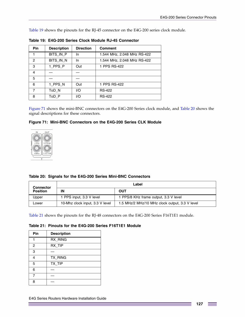
E4G-200 Series Connector Pinouts
Table 19 shows the pinouts for the RJ-45 connector on the E4G-200 series clock module.
Figure 71 shows the mini-BNC connectors on the E4G-200 Series clock module, and Table 20 shows the signal descriptions for these connectors.
Figure 71: Mini-BNC Connectors on the E4G-200 Series CLK Module
Table 21 shows the pinouts for the RJ-48 connectors on the E4G-200 Series F16T1E1 module.
Table 19: E4G-200 Series Clock Module RJ-45 Connector
Pin Description Direction Comment
1 BITS_IN_P In 1.544 MHz, 2.048 MHz RS-422
2 BITS_IN_N In 1.544 MHz, 2.048 MHz RS-422
3 1_PPS_P Out 1 PPS RS-422
4 — —
5 — —
6 1_PPS_N Out 1 PPS RS-422
7 ToD_N I/O RS-422
8 ToD_P I/O RS-422
Table 20: Signals for the E4G-200 Series Mini-BNC Connectors
Connector Position
Label
IN OUT
Upper 1 PPS input, 3.3 V level 1 PPS/8 KHz frame output, 3.3 V level
Lower 10-Mhz clock input, 3.3 V level 1.5 MHz/2 MHz/10 MHz clock output, 3.3 V level
Table 21: Pinouts for the E4G-200 Series F16T1E1 Module
Pin Description
1 RX_RING
2 RX_TIP
3 —
4 TX_RING
5 TX_TIP
6 —
7 —
8 —
1 32
E4G Series Routers Hardware Installation Guide
127
Appendix B: Technical Specifications
Table 22 shows the pinouts for the RJ-45 console port connector on the E4G-200 Series Cell Site Router.
Table 23 shows the pinouts for an RJ-45-to-DB-9 adapter.
Table 24 shows the pinouts for a T1/E1 crossover cable. This cable is used for connecting the ports on the E4G-200 Series T1/E1 module.
Table 22: RJ-45 Console Port on the E4G-200 Seires Router
Function Pin Number Direction
CTS (clear to send) 1 In
DTR (data carrier detect) 2 Out
TXD (transmit data) 3 Out
GND (ground) 4 —
GND (ground) 5 —
RXD (receive data) 6 In
DSR (data set ready) 7 In
RTS (request to send) 8 Out
Table 23: Pinouts for an RJ-45 to DB-9 Adapter
Signal RJ-45 Pin DB-9 Pin
CTS (clear to send) 1 8
DTR (data carrier detect) 2 6
TXD (transmit data) 3 2
GND (ground) 4 5
GND (ground) 5 5
RXD (receive data) 6 3
DSR (data set ready) 7 4
RTS (request to send) 8 7
Table 24: Pinouts for a T1/E1 RJ-48C Crossover Cable
RJ-48C Connector Pin Description
RJ-48C Connector Pin
1 RX_RING to TX_RING 4
2 RX_TIP to TX_TIP 5
3 6
4 TX_RING to RX_RING 1
5 TX_TIP to RX_RING 2
6 3
7 — —
8 — —
E4G Series Routers Hardware Installation Guide
128
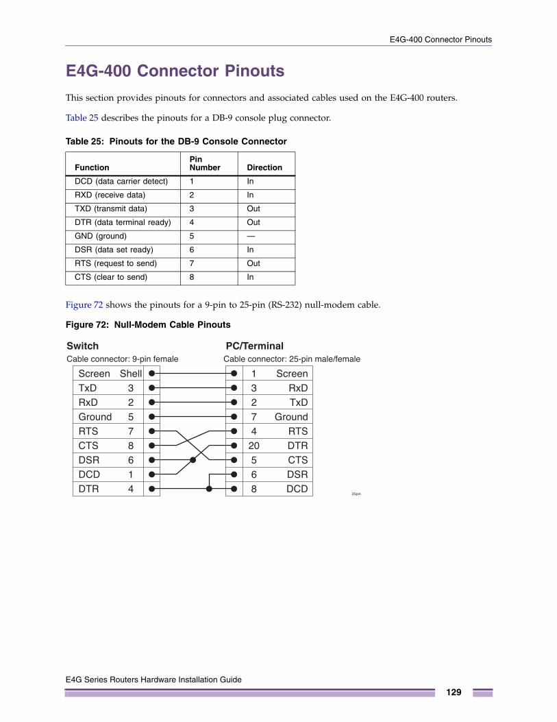
E4G-400 Connector Pinouts
E4G-400 Connector PinoutsThis section provides pinouts for connectors and associated cables used on the E4G-400 routers.
Table 25 describes the pinouts for a DB-9 console plug connector.
Figure 72 shows the pinouts for a 9-pin to 25-pin (RS-232) null-modem cable.
Figure 72: Null-Modem Cable Pinouts
Table 25: Pinouts for the DB-9 Console Connector
FunctionPin Number Direction
DCD (data carrier detect) 1 In
RXD (receive data) 2 In
TXD (transmit data) 3 Out
DTR (data terminal ready) 4 Out
GND (ground) 5 —
DSR (data set ready) 6 In
RTS (request to send) 7 Out
CTS (clear to send) 8 In
ScreenTxDRxDGroundRTSCTSDSRDCDDTR
Cable connector: 9-pin female
SwitchCable connector: 25-pin male/female
25pin
PC/Terminal
ScreenRxDTxD
GroundRTSDTRCTSDSRDCD
Shell32578614
13274
20568
E4G Series Routers Hardware Installation Guide
129

Appendix B: Technical Specifications
Figure 73 shows the pinouts for a 9-pin to 9-pin (PC-AT) null-modem serial cable.
Figure 73: PC-AT Serial Null-modem Cable Pinouts
Table 26 shows port mapping between the MRJ21 connector on the E4G-B16T1E1 module and the E1/T1 ports.
Table 26: Port Mapping between the E4G-B16T1E1 MRJ21 Connectors and T1E1 Ports
MRJ21 Connector 1 MRJ21 Connector 2
Port 1 Port 9
Port 2 Port 10
Port 3 Port 11
Port 4 Port 12
Port 5 Port 13
Port 6 Port 14
Port 7 Port 15
Port 8 Port 16
ScreenDTRTxDRxDCTSGroundDSRRTSDCD
Cable connector: 9-pin female
SwitchCable connector: 9-pin female
PC-AT Serial Port
ScreenDCDRxDTxDDTR
GroundDSRRTSCTS
Shell43285671
Shell12345678
9pin
E4G Series Routers Hardware Installation Guide
130
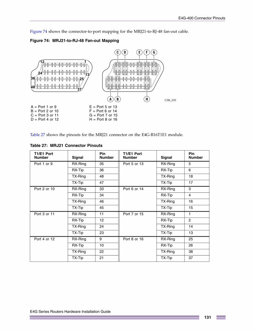
E4G-400 Connector Pinouts
Figure 74 shows the connector-to-port mapping for the MRJ21-to-RJ-48 fan-out cable.
Figure 74: MRJ21-to-RJ-48 Fan-out Mapping
Table 27 shows the pinouts for the MRJ21 connector on the E4G-B16T1E1 module.
Table 27: MRJ21 Connector Pinouts
T1/E1 Port Number Signal
Pin Number
T1/E1 Port Number Signal
Pin Number
Port 1 or 9 RX-Ring 35 Port 5 or 13 RX-Ring 5
RX-Tip 36 RX-Tip 6
TX-Ring 48 TX-Ring 18
TX-Tip 47 TX-Tip 17
Port 2 or 10 RX-Ring 33 Port 6 or 14 RX-Ring 3
RX-Tip 34 RX-Tip 4
TX-Ring 46 TX-Ring 16
TX-Tip 45 TX-Tip 15
Port 3 or 11 RX-Ring 11 Port 7 or 15 RX-Ring 1
RX-Tip 12 RX-Tip 2
TX-Ring 24 TX-Ring 14
TX-Tip 23 TX-Tip 13
Port 4 or 12 RX-Ring 9 Port 8 or 16 RX-Ring 25
RX-Tip 10 RX-Tip 26
TX-Ring 22 TX-Ring 38
TX-Tip 21 TX-Tip 37
CSR_035
1
1325
A B H
GFEDC
37
12
24
48
36
A = Port 1 or 9B = Port 2 or 10C = Port 3 or 11D = Port 4 or 12
E = Port 5 or 13F = Port 6 or 14G = Port 7 or 15H = Port 8 or 16
E4G Series Routers Hardware Installation Guide
131
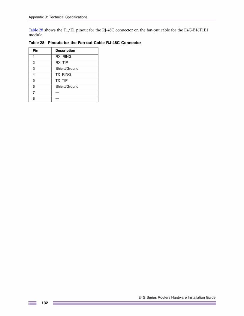
Appendix B: Technical Specifications
Table 28 shows the T1/E1 pinout for the RJ-48C connector on the fan-out cable for the E4G-B16T1E1 module.
Table 28: Pinouts for the Fan-out Cable RJ-48C Connector
Pin Description
1 RX_RING
2 RX_TIP
3 Shield/Ground
4 TX_RING
5 TX_TIP
6 Shield/Ground
7 —
8 —
E4G Series Routers Hardware Installation Guide
132

Conformity Statements
Conformity Statements
Declaration of Conformity to R&TTE Directive 1999/5/EC for the European Community, Switzerland, Norway, Iceland, and Liechtenstein
English: This equipment is in compliance with the essential requirements and other relevant provisions of Directive 1999/5/EC.
Dansk[Danish]:
Dette udstyr er i overensstemmelse med de væsentlige krav og andre relevante bestemmelser i Direktiv 1999/5/EF.
Deutsch[German]:
Dieses Gerät entspricht den grundlegenden Anforderungen und den weiteren entsprechendenVorgaben der Richtlinie 1999/5/EU.
Eesti[Estonian]:
See seade vastab direktiivi 1999/5/EÜ olulistele nõuetele ja teistele asjakohastele sätetele.
Español[Spanish]:
Este equipo cumple con los requisitos esenciales asi como con otras disposiciones de la Directiva 999/5/CE.
Français[French]:
Cet appareil est conforme aux exigences essentielles et aux autres dispositions pertinentes de la Directive 1999/5/EC.
Íslenska[Icelandic]:
Þetta tæki er samkvæmt grunnkröfum og öðrum viðeigandi ákvæðum Tilskipunar 1999/5/EC.
Italiano[Italian]:
Questo apparato é conforme ai requisiti essenziali ed agli altri principi sanciti dalla Direttiva 1999/5/CE.
Nederlands[Dutch]:
Dit apparaat voldoet aan de essentiele eisen en andere van toepassing zijnde bepalingen van de Richtlijn 1999/5/EC.
Norsk[Norwegian]:
Dette utstyret er i samsvar med de grunnleggende krav og andre relevante bestemmelser i EU-direktiv 1999/5/EF.
Português[Portuguese]
Este equipamento está em conformidade com os requisitos essenciais e outras provisões relevantes da Directiva 1999/5/EC.
Româna[Romanian]
Acest echipament este in conformitate cu cerintele esentiale si cu alte prevederi relevante ale Directivei 1999/5/EC.
Slovensko[Slovenian]:
Ta naprava je skladna z bistvenimi zahtevami in ostalimi relevantnimi pogoji Direktive 1999/5/EC.
E4G Series Routers Hardware Installation Guide
133

Appendix B: Technical Specifications
EMC Class A Statements
International—CISPR 22 Class AThis is a Class A product. In a domestic environment, this product may cause radio interference, in which case the user may be required to take adequate remedial measures.
FCC Class A
This equipment has been tested and found to comply with the limits for a Class A digital device, pursuant to Part 15 of the FCC Rules. These limits are designed to provide reasonable protection against harmful interference when the equipment is operated in a commercial environment. This equipment generates, uses, and can radiate radio frequency energy and, if not installed and used in accordance with the instruction manual, may cause harmful interference to radio communications. Operation of this equipment in a residential area is likely to cause harmful interference, in which case you are required to correct the interference at your own expense.
Canada Class AThis Class A digital apparatus complies with Canadian ICES-003.
Cet appareil numérique de la classe A est conforme à la norme NMB-003 du Canada.
Japan (VCCI Class A)This is a Class A product based on the standard of the VCCI Council. If this equipment is used in a domestic environment, radio interference may occur, in which case the user may be required to take corrective actions.
Slovensky[Slovak]:
Toto zariadenie je v zhode so základnými požiadavkami a inými príslušnými nariadeniami direktív: 1999/5/EC.
E4G Series Routers Hardware Installation Guide
134

Conformity Statements
Class A Notice for Taiwan and Other Traditional Chinese Markets
WARNING!
This is a Class A product. In a residential environment this product may cause radio interference, in which case the user may be required to take appropriate measures.
WARNING!
警告使用者:這是甲類的資訊產品,在居住的環境中使用時,可能會造成射頻干擾,在這種情況下,使用者會被要求採取某些適當的對策。
WARNING!
Telecom Approvals
FCC Part 68 NoticeThis equipment has been tested and complies with:
● 47 CFR Part 68 of FCC rules.
● TIA/EIA/IS-968, Technical Criteria for Terminal Equipment To Prevent Harm to the Telephone Network, July 2001, as adopted by the Administrative Council on Terminal Attachments (ACTA).
Canada CS-03 CertificationThe Extreme Networks E4G series routers meet the requirements of the Industry Canada label (CS-03) for telecommunications equipment.
Le présent materiel est conforme aux specifications techniques applicables d’Industrie Canada.
Observe the following general information and safety precautions:
● This equipment meets certain telecommunications network protection, operation, and safety requirements as described in the appropriate terminal equipment requirements document(s). The department does not guarantee the equipment will operate to the user’s satisfaction.
● Before installing the equipment, check that you have permission to connect it to the facilities of the local telecommunications company. The equipment must also be installed using an acceptable method of connection. The customer should be aware that compliance with the above conditions may not prevent degradation of service in some situations.
警告:此为A级产品,在生活环境中,该产品可能造成线电干扰。在这种情下,可能需要用户对干扰采取切实可行的措施。
E4G Series Routers Hardware Installation Guide
135
Appendix B: Technical Specifications
● Repairs to certified equipment should be coordinated by a representative designated by the supplier. Any repairs or alterations made by the user to this equipment, or any equipment malfunctions, may cause the telecommunications company to request that the user disconnect the equipment.
● Ensure that the electrical ground connections of the power utility, telephone lines, and internal metallic water pipe system, if present, are connected together. This precaution may be particularly important in rural areas.
Japan: JATE Green BookThe Extreme Networks E4G series routers meet the requirements of the Japan Approvals Institute for Telecommunications Equipment (JATE). The certification ID number is pending at the time of publication.
GR-1089-CORE Issue 6 Documentation Statements
ESD MitigationThis equipment may be ESD-sensitive. Always use an ESD ankle or wrist strap before handling equipment. Connect the equipment end of the ESD strap to an unfinished surface of the equipment chassis or to the ESD jack on the equipment if provided.
Telcordia GR-1089 NEBS Standard for Electromagnetic Compatibility and Safety
WARNING!
The Ethernet ports of the equipment and its sub-assemblies are suitable only for intra-building connections (within the same building) or for connections to unexposed wiring or cabling. (See the conditions listed above.) The Ethernet ports of this equipment or its sub-assemblies must not be metallically connected to interfaces that connect to the outside plant (OSP) or its wiring. Ethernet interfaces are designed for use only as intra-building interfaces (described as Type 2 or Type 4 ports in GR-1089-CORE, Issue 6) and require isolation from the exposed OSP wiring. The addition of Primary Protectors is not sufficient protection to connect these interfaces metallically to OSP wiring.
This warning does not apply to T1/E1 ports because T1/E1 ports have built-in isolation and surge protection that allows them to be connected to OSP wiring.
Intrabuilding Lightning Surge and AC Power Fault
WARNING!
The E4G series router does not require shielded LAN or WAN cables for compliance with EMC or safety requirements.
For compliance with NEBS GR-1089 Issue 6, however, shielded cables may be required, depending on your application. When shielded cables are required, ports shall be grounded at both ends of the cable.
E4G Series Routers Hardware Installation Guide
136
Conformity Statements
Equipment Bonding Networks
This equipment is suitable for installations utilizing the Common Bonding Network (CBN).
Equipment Interfacing with AC Power Ports
This equipment shall be connected to AC mains provided with a surge protective device (SPD) at the service equipment complying with NFPA 70, the National Electrical Code (NEC).
E4G Series Routers Hardware Installation Guide
137

Appendix B: Technical Specifications
E4G Series Routers Hardware Installation Guide
138
Index
AAC power supply
features, 24installing, 59LEDs, 24replacing, 75specifications, 123
access, restricted, 33alarms cable
connecting, 55pinout, 126
alarms interface, E4G-200, 16alert, power supply, 24amperage, calculating for UPS, 44ANSI standards, 45automatic failover, setting up, 22
Bbattery disposal, 100bend radius, 40, 69BICSI standards, 38BITS-IN interface
E4G-200 router, 17E4G-400 router, 20
building codes, 32Building Industry Consulting Service International. SeeBICSIBuilding Integrated Timing Supply. See BITS.
Ccabinet specifications, 35cable
fiber optic, 40installation recommendations, 38labeling, 38types and distances, 41
cable, timing, 54cabling standards
ANSI, 45BICSI, 38
clock module, E4G-200connector pinouts, 127features, 17installing, 53replacing, 88
combination ports, 22commercial building standards, 45configuration, initial, 71
conformity statements, 133connector jackets, RJ-45, 42connector pinouts
alarms cable, 126DB-9 console connector, 129E4G-200 clock module, 127null-modem cable, 129null-modem serial cable, 130RJ-45 console port, 128RJ-45-to-DB-9 adapter, 128RJ-48C, 132T1/E1 ports, 127, 131
console portlocation, 14, 15, 20settings, 71
conventions, text, 8
DDB-9 pinouts, 129DC cable, preparing, 51, 60DC power suppl
installing, 60DC power supply
features, 24grounding, 62, 80replacing, 78specifications, 125
DC power, connecting, 52Summit 350 W DC power supply, 63, 80
DC-I battery return configuration, 45design standards, 45
EE4G router family features, 13E4G-200 CLK module, 17E4G-200 router
features, 14grounding, 50installing, 48removing, 90space requirements, 37specifications, 109, 113
E4G-200 series routerLEDS, 18
E4G-200-12x routerfeatures, 15LEDS, 19
E4G-400 routerfeatures, 20
E4G Series Routers Hardware Installation Guide
139

Index
front-mount installation, 58grounding, 36, 62installing, 56LEDs, 22mid-mount installation, 57removing, 91, 92space requirements, 36specifications, 117
E4G-B16T1E1 option cardfeatures, 26installing, 67
electrical codes, 33electrostatic discharge. See ESDenvironmental requirements
building codes, 32electrical codes, 33equipment location, 33humidity, 34temperature, 34
equipment rackgrounding, 36mechanical recommendations, 35mounting holes, 35securing, 36service access, 36space requirements, 36
ESDdischarge from cable, 39system protection, 35
FF16T1E1 module, 17
installing, 54replacing, 89
fan module, replacing, 86fan specifications
E4G-400 router, 117fan-out cable
connecting, 70pinouts, 131
featuresAC power supply, 24clock module, 17DC power supply, 24E4G family, 13E4G-200 router, 14E4G-200 series F16T1E1 module, 17E4G-200-12x router, 15E4G-400 router, 20E4G-B16T1E1 option card, 26T1/E1 module, 17XGM3S-2sf option card, 25XGM3S-2xf option card, 26XGM3SB-4sf option card, 26
fiber optic cablebend radius, 40types and distances, 41
front-mount position, E4G router, 58
GGR-1089-CORE statements, 135, 136grounding
racks, 36requirements, 45wiring closet, 33
Hhumidity, 34
Iindustry standards, 45initial login, 72installation
AC power supply, 59DC power supply, 60E4G-200 clock module, 53E4G-200 router, 48E4G-400 router, 56port option cards, 67T1/E1 module, 54
installation site, outdoor, 37IP settings, configuring, 72
Llabeling system for cables, 38Latency, 110, 114, 118
E4G-200, 110, 114E4G-400, 118Summit x460, 110, 114, 118
latencysummit x460, 110, 114, 118
LEDsAC power supply, 24DC power supply, 24E4G-200 series router, 18, 19E4G-400 router, 22
local management connection, 71logging in to the router, 72
Mmaximum cable distances, 41mid-mount position, E4G-400, 57mobile backhaul architecture, 14MRJ21 port mapping, 130MRJ21-to-RJ-45 fan-out cable, 69
Nnull-modem cable pinouts, 129
Ooperating environment requirements, 34optical modules, 28
E4G Series Routers Hardware Installation Guide
140

Index
optical safety, 100outdoor installation site, 37
PPC-AT serial null-modem cable pinouts, 130physical layer problems, 42pinouts
alarms connector, 126clock module, 127DB-9 console connector, 129MRJ21 connector, 131null-modem cable, 129PC-AT serial null-modem cable, 130RJ-45 console port connector, 128RJ-45-to-DB-9 adapter, 128RJ-48 connector, 132T1/E1 crossover cable
connector pinouts
T1/E1 crossover cable, 128T1/E1 ports, 127
plenum-rated cable, 39port mapping, MRJ21, 130port option cards
installing, 67locations, 21replacing, 87
portscombination, 22console port settings, 71E4G-B16T1E1 module, 69Gigabit Ethernet, 20SFP+, 26T1/E1, 17, 26XFP, 26
power requirementspower cable, 99power supplies, 43
power supply alert, 24power supply unit (PSU)
300 W AC, 123300 W DC, 125Summit X460 DC, 124
pre-installation requirements, 47
RR&TT Directive, 133rack specifications
grounding, 36mechanical recommendations, 35mounting holes, 35securing to floor, 36space requirements, 36standards, 35
radio frequency interference. See RF interferenceredundant power configuration, 24redundant uplink ports, 22related publications, 8
removingAC power supply, 76DC power supply, 78E4G-400 router, 92fan module, 86
replacementAC power supply, 75DC power supply, 78E4G-200 clock module, 88fan module, 86port option card, 87T1/E1 module, 89
requirementsgrounding, 48power cable, 99pre-installation, 47
restricted access, 33RF interference
patch panel installation, 38preventing, 42
RJ-45 cable, 42RJ-45 console port, 128RJ-45-to-DB-9 adapter, 128rules for redundant uplink ports, 22
Ssafety information in German, 102safety requirements, 95safety requirements. See environmental requirementsservice access to the rack, 36signal quality and RF interference, 42site planning process, 32slack in cable, 38space requirements, rack, 36specifications
300 W DC power supply, 125AC power supply, 123E4G-200 router, 109, 113E4G-400 fan, 117E4G-400 router, 117Summit X460 DC power supply, 124
stacking support, 20standards
cabling, 38, 45commercial building, 45grounding, 45
startup, initial, 71statements of conformity, 133Summit X460 DC power supply
specifications, 124Synchronous Ethernet, 20
TT1/E1 crossover cable, 128T1/E1 module
installing, 54replacing, 89
E4G Series Routers Hardware Installation Guide
141
Index
T1/E1 portsconnecting, 69E4G-200 series router, 17
technical specificationsE4G-200 router, 109, 113E4G-400 router, 117
Telco environment, 96telecommunications certification approvals, 135temperature, wiring closet, 34text conventions, 8time-of-day input/output connection, 54timing cable, 54timing cables, connecting, 54, 69timing interfaces
E4G-200 router, 17E4G-400 router, 20
timing moduleconnector pinouts, 127installing, 53replacing, 88
timing module, E4G-200, 17transition time, UPS, 45
Uunshielded twisted pair. See UTPuplink redundancy
on E4G-400 router, 22setting up, 22
UPS (uninterruptible power supply), 44UTP cable
discharge ESD, 39RF interference, 42
Wwiring closet
electrostatic discharge, 35floor coverings, 33grounding, 33humidity, 34rack, securing, 36temperature, 34
wiring terminals, 36
XXGM3S-2sf option card
features, 25installing, 67
XGM3S-2xf option cardfeatures, 26installing, 67
XGM3SB-4sf option cardfeatures, 26installing, 67
E4G Series Routers Hardware Installation Guide
142