Embed Size (px)
Citation preview
Extreme Networks EAS 100-24t Switch Hardware Installation ManualLayer 2 Managed Gigabit Switch
Release 1.00
Extreme Networks, Inc.3585 Monroe StreetSanta Clara, California 95051(888) 257-3000(408) 579-2800
http://www.extremenetworks.com
Published: July 2011Part number: 120703-00 Rev. 01

AccessAdapt, Alpine, Altitude, BlackDiamond, Direct Attach, EPICenter, ExtremeWorks Essentials, Ethernet Everywhere, Extreme Enabled, Extreme Ethernet Everywhere, Extreme Networks, Extreme Standby Router Protocol, Extreme Turbodrive, Extreme Velocity, ExtremeWare, ExtremeWorks, ExtremeXOS, Go Purple Extreme Solution, ExtremeXOS ScreenPlay, ReachNXT, Ridgeline, Sentriant, ServiceWatch, Summit, SummitStack, Triumph, Unified Access Architecture, Unified Access RF Manager, UniStack, XNV, the Extreme Networks logo, the Alpine logo, the BlackDiamond logo, the Extreme Turbodrive logo, the Summit logos, and the Powered by ExtremeXOS logo are trademarks or registered trademarks of Extreme Networks, Inc. or its subsidiaries in the United States and/or other countries.
sFlow is the property of InMon Corporation.
Specifications are subject to change without notice.
All other registered trademarks, trademarks, and service marks are property of their respective owners.
© 2011 Extreme Networks, Inc. All Rights Reserved.
Extreme Networks EAS 100-24t Switch Hardware Installation Manual
2
Table of Contents
Preface.........................................................................................................................................................5
Intended Readers.....................................................................................................................................................5Typographical Conventions......................................................................................................................................5Notes, Cautions, and Warnings................................................................................................................................6Safety Instructions....................................................................................................................................................6
Precautions .......................................................................................................................................................6General Precautions for Rack-Mountable Products ..........................................................................................8
Protecting Against Electrostatic Discharge...............................................................................................................9
Chapter 1: Introduction............................................................................................................................11
Ports .......................................................................................................................................................................11LED Indicators........................................................................................................................................................12Front-Panel Description..........................................................................................................................................13Rear Panel Description ..........................................................................................................................................13Side Panel Description ...........................................................................................................................................14Gigabit Combo Ports ..............................................................................................................................................14
Chapter 2: Installation..............................................................................................................................17
Package Contents ..................................................................................................................................................17Before You Connect to the Network .......................................................................................................................17Installing the Switch without the Rack ....................................................................................................................18Installing the Switch in a Rack................................................................................................................................18Mounting the Switch in a Standard 19" Rack .........................................................................................................19
Power on AC Power........................................................................................................................................19Power Failure ..................................................................................................................................................19
Chapter 3: Connecting the Switch ..........................................................................................................21
Switch to End Node................................................................................................................................................21Switch to Hub or Switch .........................................................................................................................................22
Chapter 4: Introduction to Switch Management....................................................................................23
Management Options .............................................................................................................................................23Web-based Management Interface ........................................................................................................................23SNMP-Based Management....................................................................................................................................23Connecting the Console Port (RS-232 DCE) .........................................................................................................23First Time Connecting to the Switch ......................................................................................................................25Password Protection ..............................................................................................................................................25SNMP Settings .......................................................................................................................................................26
Traps ...............................................................................................................................................................27IP Address Assignment ..........................................................................................................................................27
Chapter 5: Web-Based Switch Configuration ........................................................................................31
Introduction.............................................................................................................................................................31Login to Web Manager ...........................................................................................................................................31Web-based User Interface .....................................................................................................................................32
Areas of the User Interface .............................................................................................................................32
Extreme Networks EAS 100-24t Switch Hardware Installation Manual
3
Table of Contents
Web Pages.............................................................................................................................................................34
Appendix A: Technical Specifications ...................................................................................................35General...................................................................................................................................................................35Physical and Environmental ...................................................................................................................................37Performance...........................................................................................................................................................37LED Indicators........................................................................................................................................................37
Appendix B: Cables and Connectors .....................................................................................................39Ethernet Cable .......................................................................................................................................................39Console Cable........................................................................................................................................................40
Extreme Networks EAS 100-24t Switch Hardware Installation Manual
4
Preface
This manual describes the installation, maintenance, and configuration of the EAS 100-24t.
Intended ReadersThe Extreme Networks EAS 100-24t Switch Hardware Installation Manual contains information for setup and management of the switch. This manual is intended for network managers familiar with network management concepts and terminology.
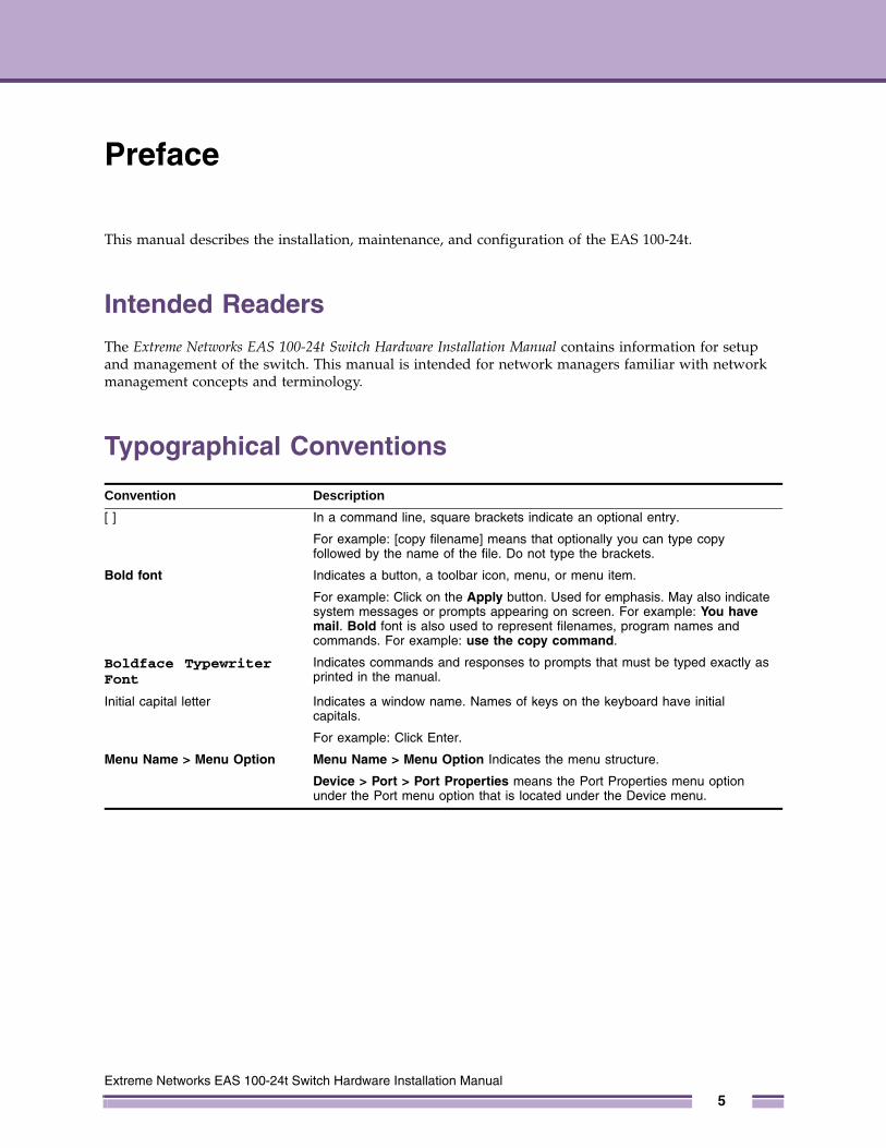
Typographical Conventions
Convention Description
[ ] In a command line, square brackets indicate an optional entry.
For example: [copy filename] means that optionally you can type copy followed by the name of the file. Do not type the brackets.
Bold font Indicates a button, a toolbar icon, menu, or menu item.
For example: Click on the Apply button. Used for emphasis. May also indicate system messages or prompts appearing on screen. For example: You have mail. Bold font is also used to represent filenames, program names and commands. For example: use the copy command.
Boldface Typewriter Font
Indicates commands and responses to prompts that must be typed exactly as printed in the manual.
Initial capital letter Indicates a window name. Names of keys on the keyboard have initial capitals.
For example: Click Enter.
Menu Name > Menu Option Menu Name > Menu Option Indicates the menu structure.
Device > Port > Port Properties means the Port Properties menu option under the Port menu option that is located under the Device menu.
Extreme Networks EAS 100-24t Switch Hardware Installation Manual
5
Preface
Notes, Cautions, and Warnings
NOTE
A NOTE indicates important information that helps make better use of the device.
CAUTION
A CAUTION indicates either potential damage to hardware or loss of data and tells how to avoid the problem.
WARNING!
A WARNING indicates a potential for property damage, personal injury, or death.
Safety InstructionsUse the following safety guidelines to ensure your own personal safety and to help protect your system from potential damage. Throughout this document, the caution icon ( ) is used to indicate cautions and precautions that you need to review and follow.
PrecautionsTo reduce the risk of bodily injury, electrical shock, fire, or damage to the equipment, observe the following precautions.
● Observe and follow service markings.
● Do not service any product except as explained in your system documentation.
● Opening or removing covers that are marked with the triangular symbol with a lightning bolt may expose you to electrical shock.
● Only a trained service technician should service components inside these compartments.
● If any of the following conditions occur, unplug the product from the electrical outlet and replace the part or contact your trained service provider:
● The power cable, extension cable, or plug is damaged.
● An object has fallen into the product.
● The product has been exposed to water.
● The product has been dropped or damaged.
● The product does not operate correctly when you follow the operating instructions.
● Keep your system away from radiators and heat sources. Also, do not block cooling vents.
● Do not spill food or liquids on your system components, and never operate the product in a wet environment.
Extreme Networks EAS 100-24t Switch Hardware Installation Manual
6

Safety Instructions
● Do not push any objects into the openings of your system. Doing so can cause fire or electric shock by shorting out interior components.
● Use the product only with approved equipment.
● Allow the product to cool before removing covers or touching internal components.
● Operate the product only from the type of external power source indicated on the electrical ratings label. If you are not sure of the type of power source required, consult your service provider or local power company.
● To help avoid damaging your system, be sure the voltage on the power supply is set to match the power available at your location:
● 115 volts (V)/60 hertz (Hz) in most of North and South America and some Far Eastern countries such as South Korea and Taiwan
● 100 V/50 Hz in eastern Japan and 100 V/60 Hz in western Japan
● 230 V/50 Hz in most of Europe, the Middle East, and the Far East
● Also, be sure that attached devices are electrically rated to operate with the power available in your location.
● Use only approved power cable(s). If you have not been provided with a power cable for your system or for any AC-powered option intended for your system, purchase a power cable that is approved for use in your country. The power cable must be rated for the product and for the voltage and current marked on the product's electrical ratings label. The voltage and current rating of the cable should be greater than the ratings marked on the product.
● To help prevent electric shock, plug the system and peripheral power cables into properly grounded electrical outlets. These cables are equipped with three-prong plugs to help ensure proper grounding. Do not use adapter plugs or remove the grounding prong from a cable. If you must use an extension cable, use a 3-wire cable with properly grounded plugs.
● Observe extension cable and power strip ratings. Make sure that the total ampere rating of all products plugged into the extension cable or power strip does not exceed 80 percent of the ampere ratings limit for the extension cable or power strip.
● To help protect your system from sudden, transient increases and decreases in electrical power, use a surge suppressor, line conditioner, or uninterruptible power supply (UPS).
● Position system cables and power cables carefully; route cables so that they cannot be stepped on or tripped over. Be sure that nothing rests on any cables.
● Do not modify power cables or plugs. Consult a licensed electrician or your power company for site modifications. Always follow your local/national wiring rules.
● When connecting or disconnecting power to hot-pluggable power supplies, if offered with your system, observe the following guidelines:
● Install the power supply before connecting the power cable to the power supply.
● Unplug the power cable before removing the power supply.
● If the system has multiple sources of power, disconnect power from the system by unplugging all power cables from the power supplies.
● Move products with care; ensure that all casters and/or stabilizers are firmly connected to the system. Avoid sudden stops and uneven surfaces.
Extreme Networks EAS 100-24t Switch Hardware Installation Manual
7

Preface
General Precautions for Rack-Mountable ProductsObserve the following precautions for rack stability and safety. Also, refer to the rack installation documentation accompanying the system and the rack for specific caution statements and procedures.
● Systems are considered to be components in a rack. Thus, “component” refers to any system as well as to various peripherals or supporting hardware.
● Before working on the rack, make sure that the stabilizers are secured to the rack, extended to the floor, and that the full weight of the rack rests on the floor. Install front and side stabilizers on a single rack or front stabilizers for joined multiple racks before working on the rack.
● Always load the rack from the bottom up, and load the heaviest item in the rack first.
● Make sure that the rack is level and stable before extending a component from the rack.
● Use caution when pressing the component rail release latches and sliding a component into or out of a rack; the slide rails can pinch your fingers.
● After a component is inserted into the rack, carefully extend the rail into a locking position, and then slide the component into the rack.
● Do not overload the AC supply branch circuit that provides power to the rack. The total rack load should not exceed 80 percent of the branch circuit rating.
● Ensure that proper airflow is provided to components in the rack.
● Do not step on or stand on any component when servicing other components in a rack.
NOTE
A qualified electrician must perform all connections to DC power and to safety grounds. All electrical wiring must comply with applicable local, regional or national codes and practices.
WARNING!
Never defeat the ground conductor or operate the equipment in the absence of a suitably installed ground conductor. Contact the appropriate electrical inspection authority or an electrician if you are uncertain that suitable grounding is available.
WARNING!
The system chassis must be positively grounded to the rack cabinet frame. Do not attempt to connect power to the system until grounding cables are connected. A qualified electrical inspector must inspect completed power and safety ground wiring. An energy hazard will exist if the safety ground cable is omitted or disconnected.
WARNING!
Do not replace the battery with an incorrect type. The risk of explosion exists if the replacement battery is not the correct lithium battery type. Dispose of used batteries according to the instructions.
Extreme Networks EAS 100-24t Switch Hardware Installation Manual
8

Protecting Against Electrostatic Discharge
Protecting Against Electrostatic DischargeStatic electricity can harm delicate components inside your system. To prevent static damage, discharge static electricity from your body before you touch any of the electronic components, such as the microprocessor. You can do so by periodically touching an unpainted metal surface on the chassis.
You can also take the following steps to prevent damage from electrostatic discharge (ESD):
1 When unpacking a static-sensitive component from its shipping carton, do not remove the component from the antistatic packing material until you are ready to install the component in your system. Just before unwrapping the antistatic packaging, be sure to discharge static electricity from your body.
2 When transporting a sensitive component, first place it in an antistatic container or packaging.
3 Handle all sensitive components in a static-safe area. If possible, use antistatic floor pads, workbench pads and an antistatic grounding strap.
Extreme Networks EAS 100-24t Switch Hardware Installation Manual
9

Preface
Extreme Networks EAS 100-24t Switch Hardware Installation Manual
10
1
Extreme Networks EAS 100-2
C H A P T E R
Introduction
PortsThe EAS 100-24t includes the following types of ports:
● Twenty 10/100/1000 BASE-TX ports
● Four 10/100/1000BASE-T/SFP combo ports
● One female DCE RS-232 DB-9 console port
The following table lists the features and compatibility for each type of port present in the EAS 100-24t.
SFP Combo: SFP Transceivers Supported:
• 10051: SX mini-GBIC - Mini-GBIC SFP, 1000BASE-SX, MMF 220 & 550 meters, LC connector
• 10052: LX mini-GBIC - Mini-GBIC SFP, 1000BASE-LX, MMF 220 & 550 meters, SMF 10km, LC connector
• 10056: 1000BASE-BX-D BiDi SFP - 1000BASE-BX-D SFP, 1490-nm TX/1310-nm RX wavelength
• 10057: 1000BASE-BX-U BiDi SFP - 1000BASE-BX-U SFP, 1310-nm TX/1490-nm RX wavelength
Compliant to following standards:
• IEEE 802.3z compliance
• IEEE 802.3u compliance
1000BASE-T Combo:
IEEE 802.3 compliant
IEEE 802.3u compliant
IEEE 802.3ab compliant
IEEE 802.3x flow control support in full-duplex
100BASE-FX: IEEE 802.3 compliant
IEEE 802.3u compliant
IEEE 802.3x flow control support in full-duplex
4t Switch Hardware Installation Manual
11
Chapter 1: Introduction
NOTE
The SFP combo ports on the switch cannot be used simultaneously with the corresponding 1000BASE-T ports. If both ports are in use at the same time (ex. port 21 of the SFP and port 21 of the 1000BASE-T), the SFP ports will take priority over the combo ports and render the 1000BASE-T ports inoperable.
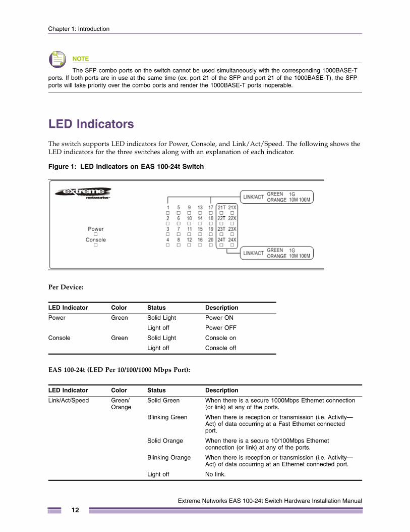
LED IndicatorsThe switch supports LED indicators for Power, Console, and Link/Act/Speed. The following shows the LED indicators for the three switches along with an explanation of each indicator.
Figure 1: LED Indicators on EAS 100-24t Switch
Per Device:
EAS 100-24t (LED Per 10/100/1000 Mbps Port):
LED Indicator Color Status Description
Power Green Solid Light Power ON
Light off Power OFF
Console Green Solid Light Console on
Light off Console off
LED Indicator Color Status Description
Link/Act/Speed Green/Orange
Solid Green When there is a secure 1000Mbps Ethernet connection (or link) at any of the ports.
Blinking Green When there is reception or transmission (i.e. Activity—Act) of data occurring at a Fast Ethernet connected port.
Solid Orange When there is a secure 10/100Mbps Ethernet connection (or link) at any of the ports.
Blinking Orange When there is reception or transmission (i.e. Activity—Act) of data occurring at an Ethernet connected port.
Light off No link.
Extreme Networks EAS 100-24t Switch Hardware Installation Manual
12
Front-Panel Description
EAS 100-24t (LED Per 10/100/1000 Mbps SFP Port):
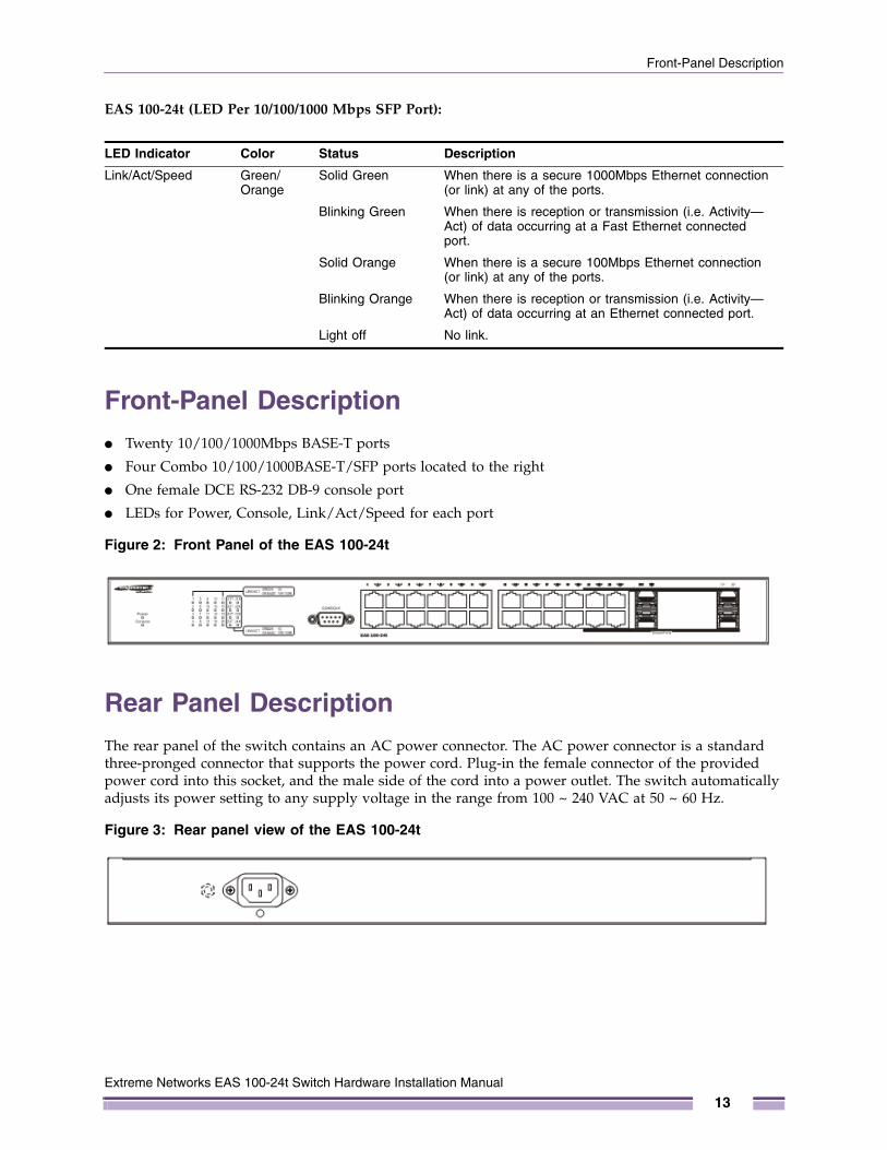
Front-Panel Description● Twenty 10/100/1000Mbps BASE-T ports
● Four Combo 10/100/1000BASE-T/SFP ports located to the right
● One female DCE RS-232 DB-9 console port
● LEDs for Power, Console, Link/Act/Speed for each port
Figure 2: Front Panel of the EAS 100-24t
Rear Panel DescriptionThe rear panel of the switch contains an AC power connector. The AC power connector is a standard three-pronged connector that supports the power cord. Plug-in the female connector of the provided power cord into this socket, and the male side of the cord into a power outlet. The switch automatically adjusts its power setting to any supply voltage in the range from 100 ~ 240 VAC at 50 ~ 60 Hz.
Figure 3: Rear panel view of the EAS 100-24t
LED Indicator Color Status Description
Link/Act/Speed Green/Orange
Solid Green When there is a secure 1000Mbps Ethernet connection (or link) at any of the ports.
Blinking Green When there is reception or transmission (i.e. Activity—Act) of data occurring at a Fast Ethernet connected port.
Solid Orange When there is a secure 100Mbps Ethernet connection (or link) at any of the ports.
Blinking Orange When there is reception or transmission (i.e. Activity—Act) of data occurring at an Ethernet connected port.
Light off No link.
Extreme Networks EAS 100-24t Switch Hardware Installation Manual
13
Chapter 1: Introduction
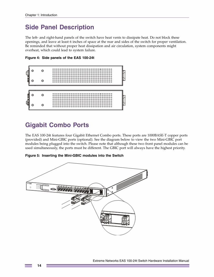
Side Panel DescriptionThe left- and right-hand panels of the switch have heat vents to dissipate heat. Do not block these openings, and leave at least 6 inches of space at the rear and sides of the switch for proper ventilation. Be reminded that without proper heat dissipation and air circulation, system components might overheat, which could lead to system failure.
Figure 4: Side panels of the EAS 100-24t
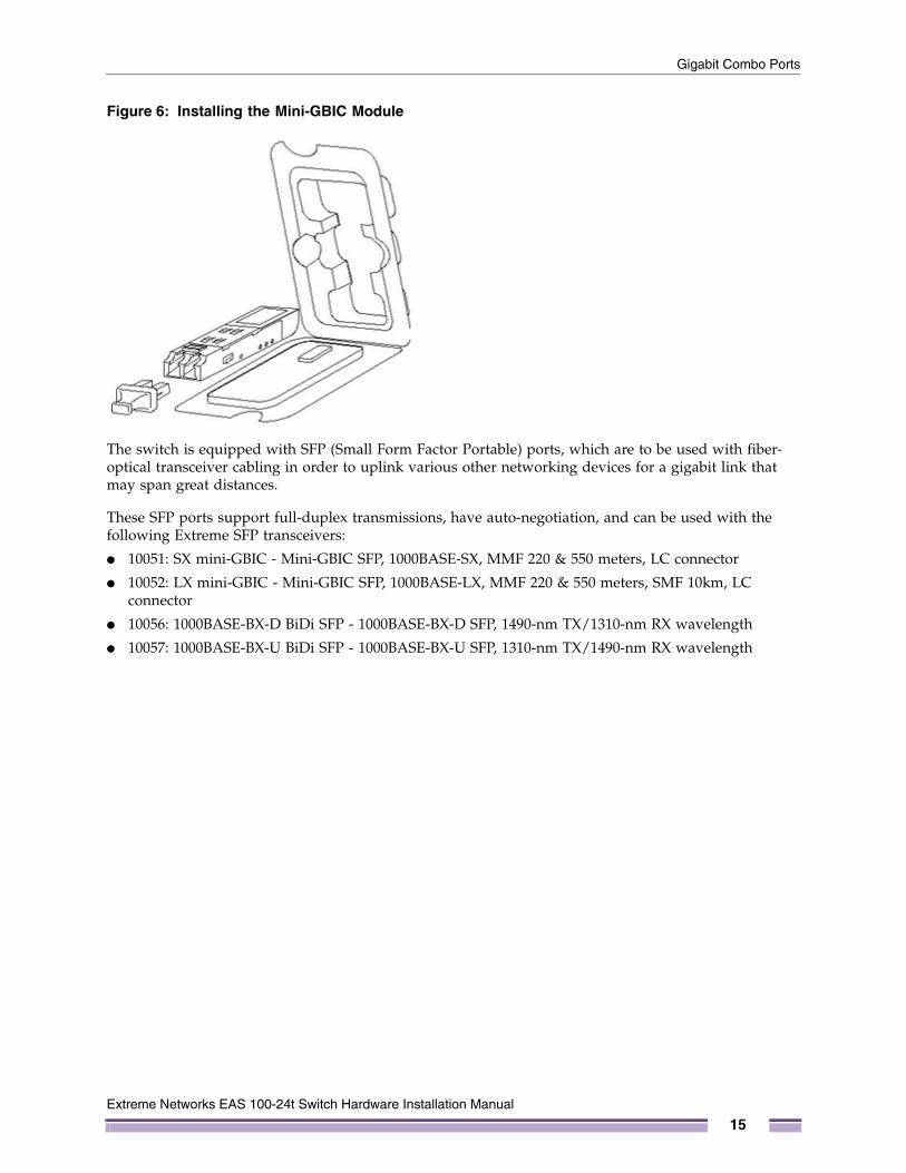
Gigabit Combo PortsThe EAS 100-24t features four Gigabit Ethernet Combo ports. These ports are 1000BASE-T copper ports (provided) and Mini-GBIC ports (optional). See the diagram below to view the two Mini-GBIC port modules being plugged into the switch. Please note that although these two front panel modules can be used simultaneously, the ports must be different. The GBIC port will always have the highest priority.
Figure 5: Inserting the Mini-GBIC modules into the Switch
Extreme Networks EAS 100-24t Switch Hardware Installation Manual
14
Gigabit Combo Ports
Figure 6: Installing the Mini-GBIC Module
The switch is equipped with SFP (Small Form Factor Portable) ports, which are to be used with fiber-optical transceiver cabling in order to uplink various other networking devices for a gigabit link that may span great distances.
These SFP ports support full-duplex transmissions, have auto-negotiation, and can be used with the following Extreme SFP transceivers:
● 10051: SX mini-GBIC - Mini-GBIC SFP, 1000BASE-SX, MMF 220 & 550 meters, LC connector
● 10052: LX mini-GBIC - Mini-GBIC SFP, 1000BASE-LX, MMF 220 & 550 meters, SMF 10km, LC connector
● 10056: 1000BASE-BX-D BiDi SFP - 1000BASE-BX-D SFP, 1490-nm TX/1310-nm RX wavelength
● 10057: 1000BASE-BX-U BiDi SFP - 1000BASE-BX-U SFP, 1310-nm TX/1490-nm RX wavelength
Extreme Networks EAS 100-24t Switch Hardware Installation Manual
15

Chapter 1: Introduction
Extreme Networks EAS 100-24t Switch Hardware Installation Manual
16
2
Extreme Networks EAS 100-2
C H A P T E R
Installation
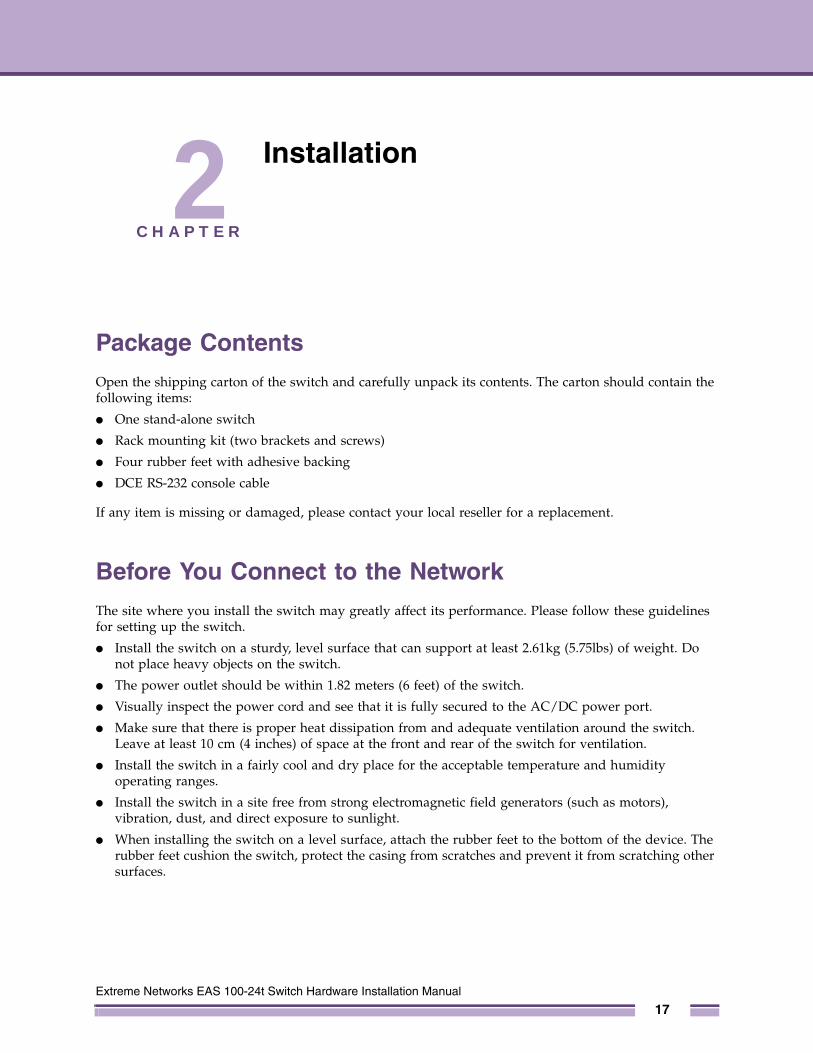
Package ContentsOpen the shipping carton of the switch and carefully unpack its contents. The carton should contain the following items:
● One stand-alone switch
● Rack mounting kit (two brackets and screws)
● Four rubber feet with adhesive backing
● DCE RS-232 console cable
If any item is missing or damaged, please contact your local reseller for a replacement.
Before You Connect to the NetworkThe site where you install the switch may greatly affect its performance. Please follow these guidelines for setting up the switch.
● Install the switch on a sturdy, level surface that can support at least 2.61kg (5.75lbs) of weight. Do not place heavy objects on the switch.
● The power outlet should be within 1.82 meters (6 feet) of the switch.
● Visually inspect the power cord and see that it is fully secured to the AC/DC power port.
● Make sure that there is proper heat dissipation from and adequate ventilation around the switch. Leave at least 10 cm (4 inches) of space at the front and rear of the switch for ventilation.
● Install the switch in a fairly cool and dry place for the acceptable temperature and humidity operating ranges.
● Install the switch in a site free from strong electromagnetic field generators (such as motors), vibration, dust, and direct exposure to sunlight.
● When installing the switch on a level surface, attach the rubber feet to the bottom of the device. The rubber feet cushion the switch, protect the casing from scratches and prevent it from scratching other surfaces.
4t Switch Hardware Installation Manual
17
Chapter 2: Installation
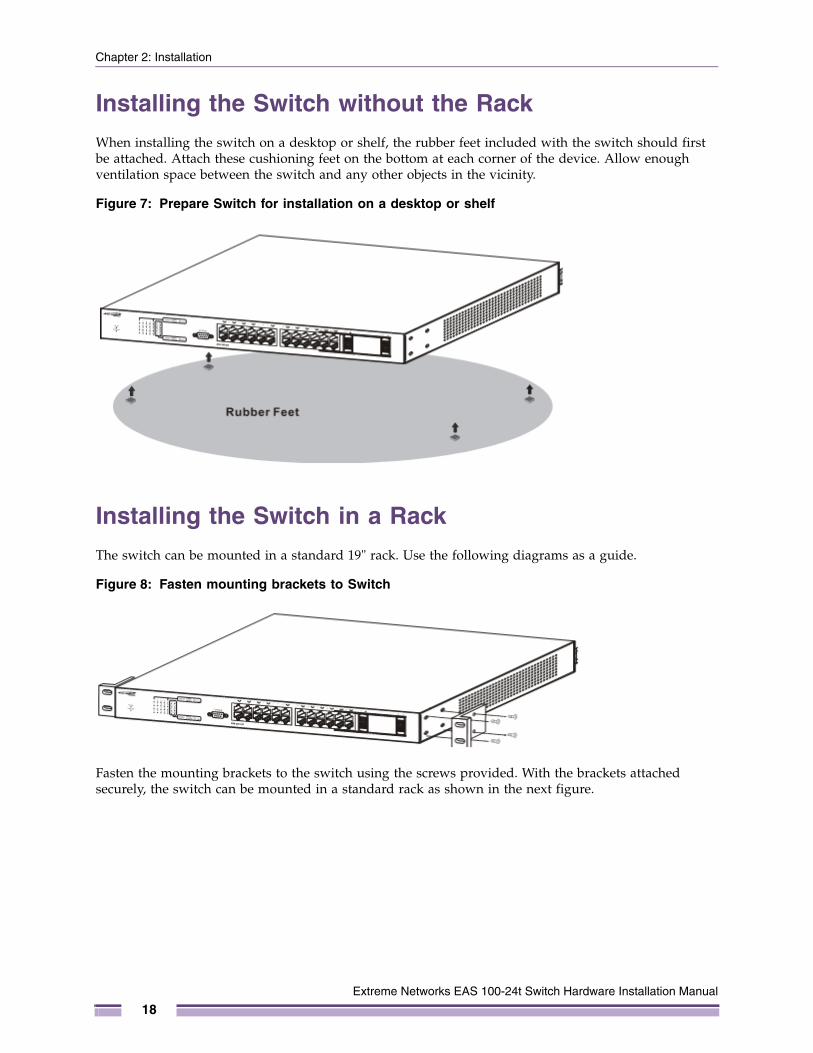
Installing the Switch without the RackWhen installing the switch on a desktop or shelf, the rubber feet included with the switch should first be attached. Attach these cushioning feet on the bottom at each corner of the device. Allow enough ventilation space between the switch and any other objects in the vicinity.
Figure 7: Prepare Switch for installation on a desktop or shelf
Installing the Switch in a RackThe switch can be mounted in a standard 19" rack. Use the following diagrams as a guide.
Figure 8: Fasten mounting brackets to Switch
Fasten the mounting brackets to the switch using the screws provided. With the brackets attached securely, the switch can be mounted in a standard rack as shown in the next figure.
Extreme Networks EAS 100-24t Switch Hardware Installation Manual
18
Mounting the Switch in a Standard 19" Rack
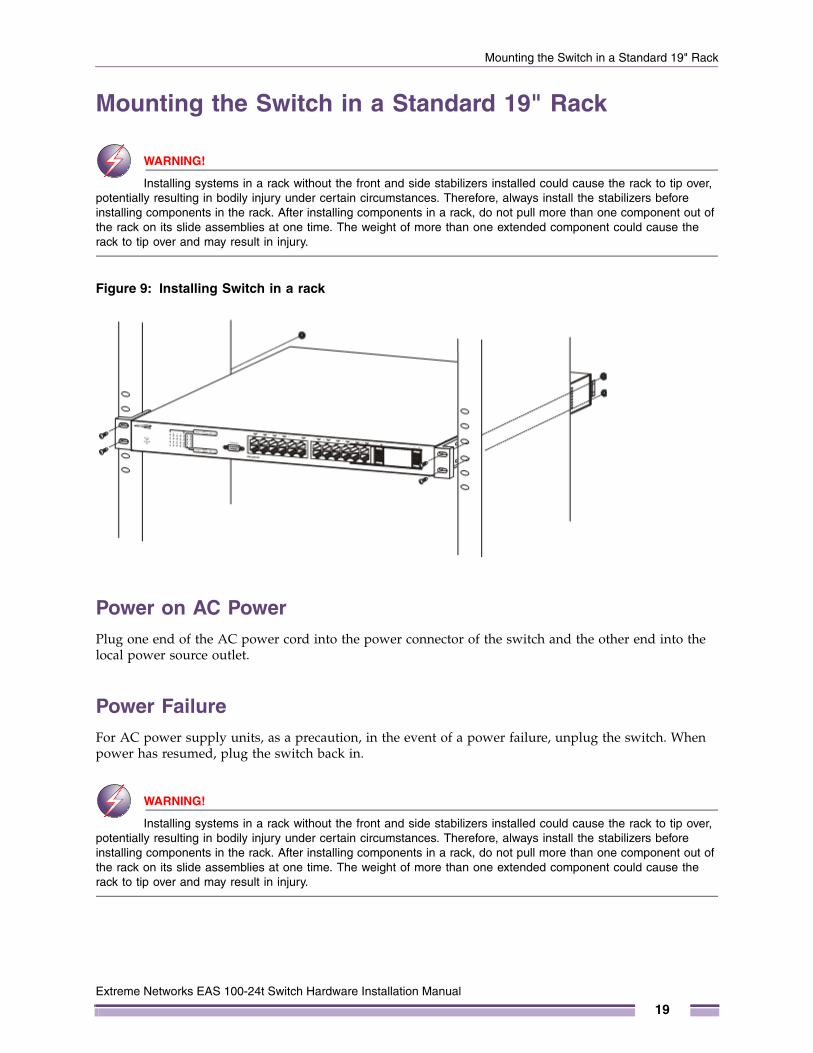
Mounting the Switch in a Standard 19" Rack
WARNING!
Installing systems in a rack without the front and side stabilizers installed could cause the rack to tip over, potentially resulting in bodily injury under certain circumstances. Therefore, always install the stabilizers before installing components in the rack. After installing components in a rack, do not pull more than one component out of the rack on its slide assemblies at one time. The weight of more than one extended component could cause the rack to tip over and may result in injury.
Figure 9: Installing Switch in a rack
Power on AC PowerPlug one end of the AC power cord into the power connector of the switch and the other end into the local power source outlet.
Power FailureFor AC power supply units, as a precaution, in the event of a power failure, unplug the switch. When power has resumed, plug the switch back in.
WARNING!
Installing systems in a rack without the front and side stabilizers installed could cause the rack to tip over, potentially resulting in bodily injury under certain circumstances. Therefore, always install the stabilizers before installing components in the rack. After installing components in a rack, do not pull more than one component out of the rack on its slide assemblies at one time. The weight of more than one extended component could cause the rack to tip over and may result in injury.
Extreme Networks EAS 100-24t Switch Hardware Installation Manual
19

Chapter 2: Installation
Extreme Networks EAS 100-24t Switch Hardware Installation Manual
20
3
Extreme Networks EAS 100-2
C H A P T E R
Connecting the Switch
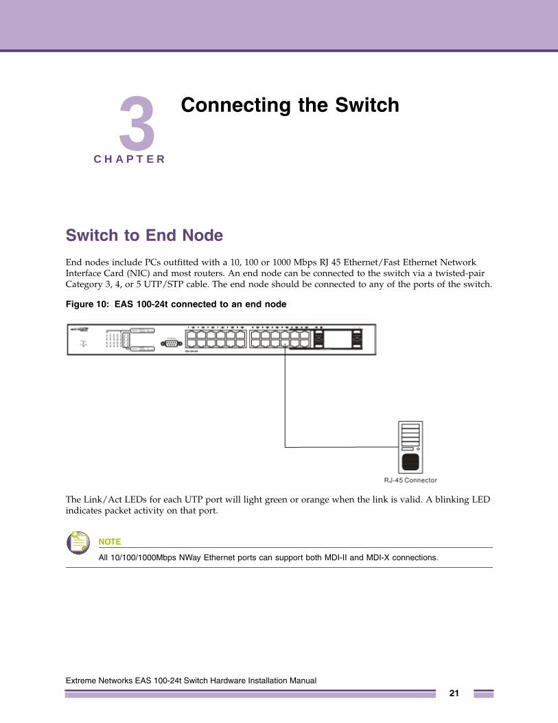
Switch to End NodeEnd nodes include PCs outfitted with a 10, 100 or 1000 Mbps RJ 45 Ethernet/Fast Ethernet Network Interface Card (NIC) and most routers. An end node can be connected to the switch via a twisted-pair Category 3, 4, or 5 UTP/STP cable. The end node should be connected to any of the ports of the switch.
Figure 10: EAS 100-24t connected to an end node
The Link/Act LEDs for each UTP port will light green or orange when the link is valid. A blinking LED indicates packet activity on that port.
NOTE
All 10/100/1000Mbps NWay Ethernet ports can support both MDI-II and MDI-X connections.
4t Switch Hardware Installation Manual
21
Chapter 3: Connecting the Switch
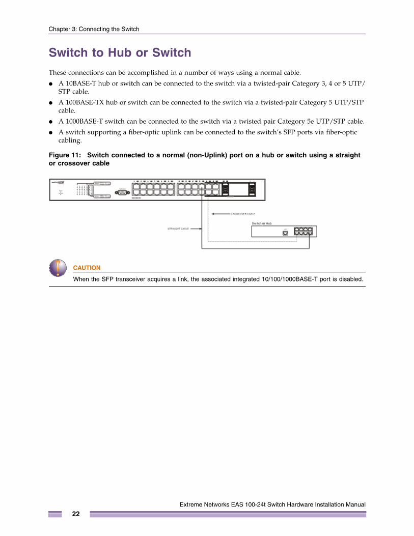
Switch to Hub or SwitchThese connections can be accomplished in a number of ways using a normal cable.
● A 10BASE-T hub or switch can be connected to the switch via a twisted-pair Category 3, 4 or 5 UTP/STP cable.
● A 100BASE-TX hub or switch can be connected to the switch via a twisted-pair Category 5 UTP/STP cable.
● A 1000BASE-T switch can be connected to the switch via a twisted pair Category 5e UTP/STP cable.
● A switch supporting a fiber-optic uplink can be connected to the switch’s SFP ports via fiber-optic cabling.
Figure 11: Switch connected to a normal (non-Uplink) port on a hub or switch using a straight or crossover cable
CAUTION
When the SFP transceiver acquires a link, the associated integrated 10/100/1000BASE-T port is disabled.
Extreme Networks EAS 100-24t Switch Hardware Installation Manual
22
4
Extreme Networks EAS 100-2
C H A P T E R
Introduction to Switch Management
Management OptionsThis system may be managed out-of-band through the console port on the front panel or in-band using Telnet. The user may also choose the Web-based management, accessible through a web browser.
Web-based Management InterfaceAfter you have successfully installed the switch, you can configure the switch, monitor the LED panel, and display statistics graphically using a Web browser, such as Firefox, Microsoft® Internet Explorer (version 6.0), Mozilla, or Netscape Navigator (version 6.2.3 and later).
SNMP-Based ManagementYou can manage the switch with an SNMP-compatible console program. The switch supports SNMP version 1.0, version 2.0 and version 3.0. The SNMP agent decodes the incoming SNMP messages and responds to requests with MIB objects stored in the database. The SNMP agent updates the MIB objects to generate statistics and counters.
Connecting the Console Port (RS-232 DCE)The switch provides an RS-232 serial port that enables a connection to a computer or terminal for monitoring and configuring the switch. This port is a female DB-9 connector, implemented as a data terminal equipment (DTE) connection.
To use the console port, you need the following equipment:
● A terminal or a computer with both a serial port and the ability to emulate a terminal.
● A null modem or crossover RS-232 cable with a female DB-9 connector for the console port on the switch.
4t Switch Hardware Installation Manual
23
Chapter 4: Introduction to Switch Management
To connect a terminal to the console port:
1 Connect the female connector of the RS-232 cable directly to the console port on the switch, and tighten the captive retaining screws.
2 Connect the other end of the cable to a terminal or to the serial connector of a computer running terminal emulation software. Set the terminal emulation software as follows:
3 Select the appropriate serial port (COM port 1 or COM port 2).
4 Set the data rate to 9600 baud.
5 Set the data format to 8 data bits, 1 stop bit, and no parity.
6 Set flow control to none.
7 Under Properties, select VT100 for Emulation mode.
8 Select Terminal keys for Function, Arrow, and Ctrl keys. Ensure that you select Terminal keys (not Windows keys).
NOTE
When you use HyperTerminal with the Microsoft® Windows® 2000 operating system, ensure that you have Windows 2000 Service Pack 2 or later installed. Windows 2000 Service Pack 2 allows you to use arrow keys in HyperTerminal's VT100 emulation. See www.microsoft.com for information on Windows 2000 service packs.
9 After you have correctly set up the terminal, plug the power cable into the power receptacle on the back of the switch. The boot sequence appears in the terminal.
10 After the boot sequence completes, the console login screen displays.
11 If you have not logged into the command line interface (CLI) program, press the Enter key at the User name and password prompts. There is no default user name and password for the switch. The administrator must first create user names and passwords. If you have previously set up user accounts, log in and continue to configure the switch.
12 Enter the commands to complete your desired tasks. Many commands require administrator-level access privileges. Read the next section for more information on setting up user accounts.
13 When you have completed your tasks, exit the session with the logout command or close the emulator program.
14 Make sure the terminal or PC you are using to make this connection is configured to match these settings.
If you are having problems making this connection on a PC, make sure the emulation is set to VT-100. You will be able to set the emulation by clicking on the File menu in you HyperTerminal window, clicking on Properties in the drop-down menu, and then clicking the Settings tab. This is where you will find the Emulation options. If you still do not see anything, try rebooting the switch by disconnecting its power supply.
Once connected to the console, the screen below will appear on your console screen. This is where the user will enter commands to perform all the available management functions. The switch will prompt the user to enter a user name and a password. Upon the initial connection, there is no user name or password and therefore just press enter twice to access the command line interface.
Extreme Networks EAS 100-24t Switch Hardware Installation Manual
24

First Time Connecting to the Switch
Figure 12: Initial screen after first connection
First Time Connecting to the Switch The switch supports user-based security that can allow you to prevent unauthorized users from accessing the switch or changing its settings. This section tells how to log onto the switch.
NOTE
The passwords used to access the switch are case-sensitive; therefore, "S" is not the same as "s."
When you first connect to the switch, you will be presented with the first login screen.
NOTE
Press Ctrl+R to refresh the screen. This command can be used at any time to force the console program in the switch to refresh the console screen.
Enter the username and password and press Enter. You will be given access to the command prompt # shown below. The default username is admin and there is no initial password.
Figure 13: Command Prompt
Password ProtectionThe switch does not have a default password. One of the first tasks when settings up the switch is to create user accounts. Once logged in using a predefined administrator-level user name, users will have privileged access to the switch's management software.
EAS 100-24t Gigabit Ethernet SwitchCommand Line InterfaceFirmware: Build 1.00.002
Copyright (C) 2000-2011 Extreme Networks. All rights reserved.
UserName:
EAS 100-24t Gigabit Ethernet SwitchCommand Line InterfaceFirmware: Build 1.00.002
Copyright (C) 2000-2011 Extreme Networks. All rights reserved.
UserName:adminPassWord:
#
Extreme Networks EAS 100-24t Switch Hardware Installation Manual
25
Chapter 4: Introduction to Switch Management
After your initial login, define new passwords for both default user names to prevent unauthorized access to the switch, and record the passwords for future reference.
To create an administrator-level account for the switch, follow these steps:
● At the CLI login prompt, enter create account admin followed by the <user name> and press the Enter key.
● The switch will then prompt the user for a password. Type the <password> used for the administrator account being created and press the Enter key.
● Again, the user will be prompted to enter the same password again to verify it. Type the same password and press the Enter key.
● Successful creation of the new administrator account will be verified by a Success message.
NOTE
Passwords are case sensitive. User names and passwords can be up to 15 characters in length.
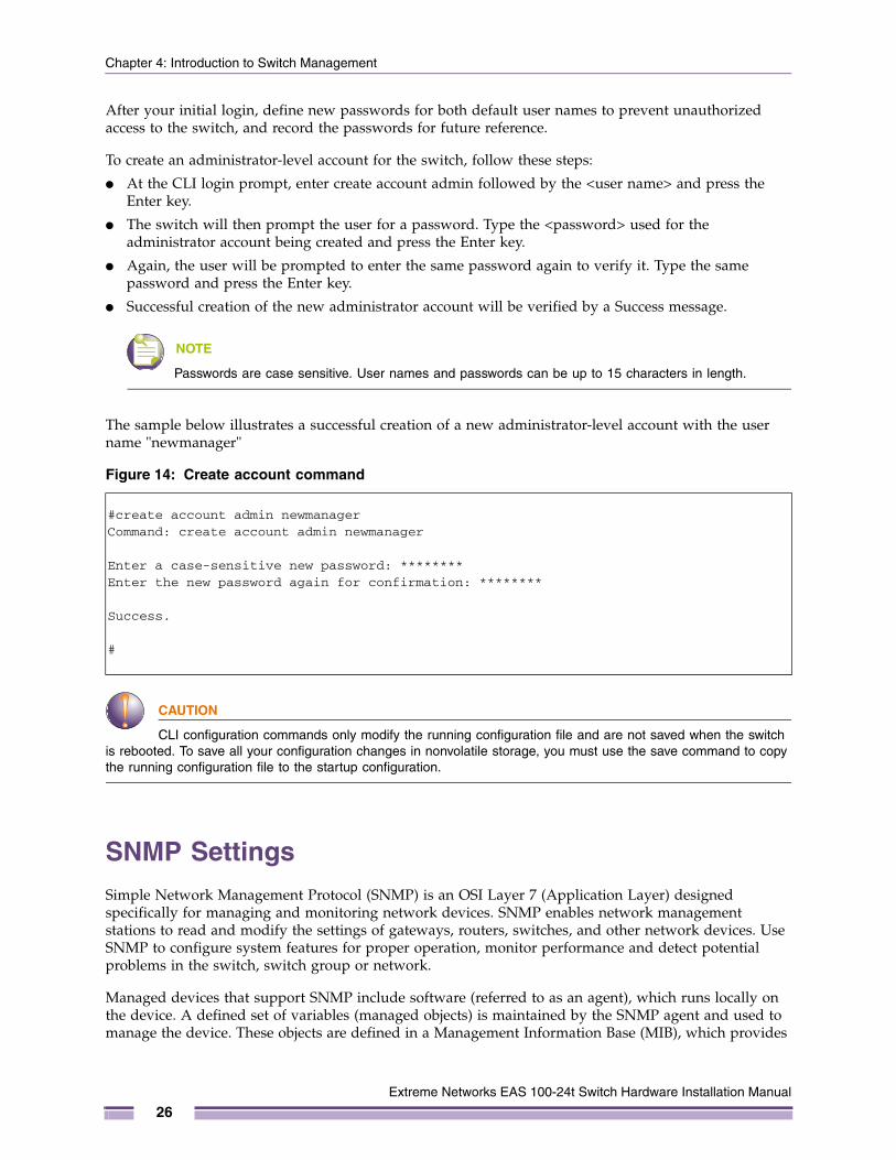
The sample below illustrates a successful creation of a new administrator-level account with the user name "newmanager"
Figure 14: Create account command
CAUTION
CLI configuration commands only modify the running configuration file and are not saved when the switch is rebooted. To save all your configuration changes in nonvolatile storage, you must use the save command to copy the running configuration file to the startup configuration.
SNMP SettingsSimple Network Management Protocol (SNMP) is an OSI Layer 7 (Application Layer) designed specifically for managing and monitoring network devices. SNMP enables network management stations to read and modify the settings of gateways, routers, switches, and other network devices. Use SNMP to configure system features for proper operation, monitor performance and detect potential problems in the switch, switch group or network.
Managed devices that support SNMP include software (referred to as an agent), which runs locally on the device. A defined set of variables (managed objects) is maintained by the SNMP agent and used to manage the device. These objects are defined in a Management Information Base (MIB), which provides
#create account admin newmanagerCommand: create account admin newmanager
Enter a case-sensitive new password: ********Enter the new password again for confirmation: ********
Success.
#
Extreme Networks EAS 100-24t Switch Hardware Installation Manual
26
IP Address Assignment
a standard presentation of the information controlled by the on-board SNMP agent. SNMP defines both the format of the MIB specifications and the protocol used to access this information over the network.
The switch supports SNMP versions 1, 2c, and 3. You can specify which version of SNMP you want to use to monitor and control the switch. The three versions of SNMP vary in the level of security provided between the management station and the network device.
In SNMP v.1 and v.2, user authentication is accomplished using 'community strings', which function like passwords. The remote user SNMP application and the switch SNMP must use the same community string. SNMP packets from any station that has not been authenticated are ignored (dropped).
The default community strings for the switch used for SNMP v.1 and v.2 management access are:
● public - Allows authorized management stations to retrieve MIB objects.
● private - Allows authorized management stations to retrieve and modify MIB objects.
SNMP v.3 uses a more sophisticated authentication process that is separated into two parts. The first part is to maintain a list of users and their attributes that are allowed to act as SNMP managers. The second part describes what each user on that list can do as an SNMP manager.
The switch allows groups of users to be listed and configured with a shared set of privileges. The SNMP version may also be set for a listed group of SNMP managers. Thus, you may create a group of SNMP managers that are allowed to view read-only information or receive traps using SNMP v.1 while assigning a higher level of security to another group, granting read/write privileges using SNMP v.3.
Using SNMP v.3 individual users or groups of SNMP managers can be allowed to perform or be restricted from performing specific SNMP management functions. The functions allowed or restricted are defined using the Object Identifier (OID) associated with a specific MIB. An additional layer of security is available for SNMP v.3 in that SNMP messages may be encrypted.
TrapsTraps are messages that alert network personnel of events that occur on the switch. The events can be as serious as a reboot (someone accidentally turned OFF the switch), or less serious like a port status change. The switch generates traps and sends them to the trap recipient (or network manager). Typical traps include trap messages for Authentication Failures and Topology Changes.
IP Address AssignmentEach switch must be assigned its own IP Address, which is used for communication with an SNMP network manager or other TCP/IP application (for example BOOTP, TFTP). The switch's default IP address is 0.0.0.0. You can change the default switch IP address to meet the specification of your networking address scheme. The switch is also assigned a unique MAC address by the factory. This MAC address cannot be changed, and can be found by entering the command "show switch" into the command line interface, as shown below.
Extreme Networks EAS 100-24t Switch Hardware Installation Manual
27

Chapter 4: Introduction to Switch Management
Figure 15: Show switch command
The switch's MAC address can also be found from the Web management program on the System Information window in the Configuration folder.
The IP address for the switch must be set before it can be managed with the Web-based manager. The switch IP address can be automatically set using BOOTP or DHCP protocols, in which case the actual address assigned to the switch must be known.
The IP address may be set using the Command Line Interface (CLI) over the console serial port as follows:
Starting at the command line prompt, enter the commands
config ipif System ipaddress xxx.xxx.xxx.xxx/yyy.yyy.yyy.yyy
Where the x's represent the IP address to be assigned to the IP interface named System and the y's represent the corresponding subnet mask.
Alternatively, you can enter config ipif System ipaddress xxx.xxx.xxx.xxx/z. Where the x's represent the IP address to be assigned to the IP interface named System and the z represents the corresponding number of subnets in CIDR notation.
The IP interface named System on the switch can be assigned an IP address and subnet mask, and then be used to connect a management station to the switch's Telnet or Web-based management agent.
EAS 100-24t:4#show switchCommand: show switch
Device Type : EAS 100-24t Gigabit Ethernet SwitchMAC Address : 00-04-96-52-83-9CIP Address : 0.0.0.0 (Manual)VLAN Name : defaultSubnet Mask : 0.0.0.0Default Gateway : 0.0.0.0Boot PROM Version : Build 1.00.002Firmware Version : Build 1.00.002Hardware Version : ASerial Number : ABCDE-10002System Name :System Location :System Contact :Spanning Tree : DisabledGVRP : DisabledIGMP Snooping : Disabled802.1X : DisabledTelnet : Enabled (TCP 23)Web : Enabled (TCP 80)RMON : DisabledSSH : DisabledSSL : DisabledCTRL+C ESC q Quit SPACE n Next Page ENTER Next Entry a All
Extreme Networks EAS 100-24t Switch Hardware Installation Manual
28
IP Address Assignment
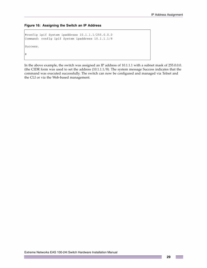
Figure 16: Assigning the Switch an IP Address
In the above example, the switch was assigned an IP address of 10.1.1.1 with a subnet mask of 255.0.0.0. (the CIDR form was used to set the address (10.1.1.1/8). The system message Success indicates that the command was executed successfully. The switch can now be configured and managed via Telnet and the CLI or via the Web-based management.
#config ipif System ipaddress 10.1.1.1/255.0.0.0Command: config ipif System ipaddress 10.1.1.1/8
Success.
#
Extreme Networks EAS 100-24t Switch Hardware Installation Manual
29

Chapter 4: Introduction to Switch Management
Extreme Networks EAS 100-24t Switch Hardware Installation Manual
30
5
Extreme Networks EAS 100-2
C H A P T E R
Web-Based Switch Configuration
IntroductionAll software functions of the switch can be managed, configured and monitored via the embedded web-based (HTML) interface. The switch can be managed from remote stations anywhere on the network through a standard browser such as Firefox, Microsoft Internet Explorer, Mozilla, or Netscape. The browser acts as a universal access tool and can communicate directly with the switch using the HTTP protocol.
The Web-based management module and the Console program (and Telnet) are different ways to access the same internal switching software and configure it. Thus, all settings encountered in web-based management are the same as those found in the console program.
Login to Web ManagerTo begin managing the switch, simply run the browser you have installed on your computer and point it to the IP address you have defined for the device. The URL in the address bar should be in the format: http://123.123.123.123, where the numbers 123 represent the IP address of the switch.
NOTE
The Factory default IP address for the switch is 0.0.0.0. The user must first configure an IP address for the switch through the console port before connecting to the Web Manager.
4t Switch Hardware Installation Manual
31
Chapter 5: Web-Based Switch Configuration
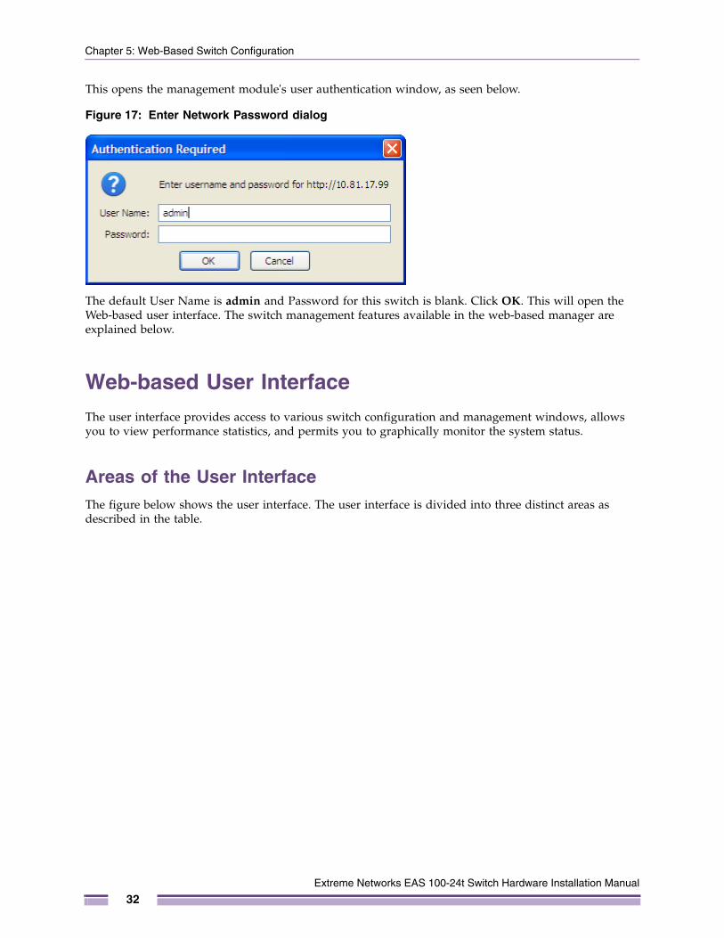
This opens the management module's user authentication window, as seen below.
Figure 17: Enter Network Password dialog
The default User Name is admin and Password for this switch is blank. Click OK. This will open the Web-based user interface. The switch management features available in the web-based manager are explained below.
Web-based User InterfaceThe user interface provides access to various switch configuration and management windows, allows you to view performance statistics, and permits you to graphically monitor the system status.
Areas of the User InterfaceThe figure below shows the user interface. The user interface is divided into three distinct areas as described in the table.
Extreme Networks EAS 100-24t Switch Hardware Installation Manual
32
Web-based User Interface
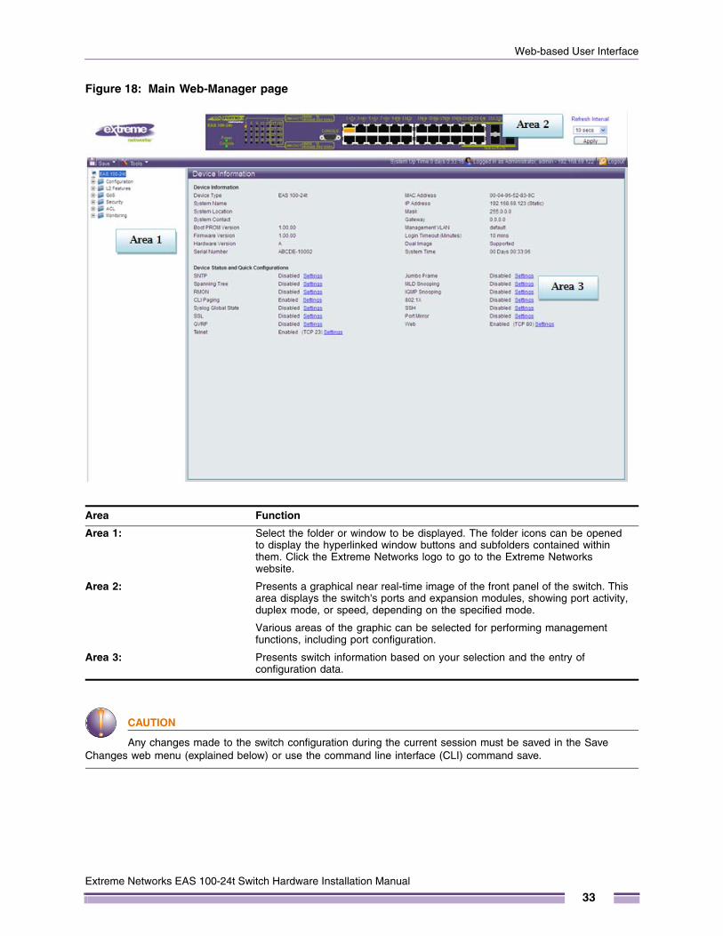
Figure 18: Main Web-Manager page
CAUTION
Any changes made to the switch configuration during the current session must be saved in the Save Changes web menu (explained below) or use the command line interface (CLI) command save.
Area Function
Area 1: Select the folder or window to be displayed. The folder icons can be opened to display the hyperlinked window buttons and subfolders contained within them. Click the Extreme Networks logo to go to the Extreme Networks website.
Area 2: Presents a graphical near real-time image of the front panel of the switch. This area displays the switch's ports and expansion modules, showing port activity, duplex mode, or speed, depending on the specified mode.
Various areas of the graphic can be selected for performing management functions, including port configuration.
Area 3: Presents switch information based on your selection and the entry of configuration data.
Extreme Networks EAS 100-24t Switch Hardware Installation Manual
33
Chapter 5: Web-Based Switch Configuration
Web PagesWhen you connect to the management mode of the switch with a Web browser, a login window is displayed. Enter a user name and password to access the switch's management mode.
Below is a list and description of the folders and main windows available in the Web interface:
● Configuration – Contains main windows concerning Device Information, System Information, Serial Port Settings, IP Address, Port Configuration, Static ARP Settings, User Accounts, System Log Configuration, MAC Address Aging Time, Web Settings, Telnet Settings, CLI Paging Settings, Firmware Information, SNTP Settings, SMTP Settings, SNMP Settings.
● L2 Features – Contains main windows concerning Jumbo Frame, 802.1Q Static VLAN, Q-in-Q, 802.1v Protocol VLAN, GVRP Settings, Asymmetric VLAN Settings, MAC-based VLAN Settings, PVID Auto Assign Settings, Port Trunking, LACP Port Settings, Traffic Segmentation, IGMP Snooping, MLD Snooping Settings, Port Mirror, Loopback Detection Settings, Spanning Tree, Forwarding & Filtering, and LLDP.
● QoS – Contains main windows concerning Bandwidth Control, Traffic Control, 802.1P Default Priority, 802.1P User Priority, QoS Scheduling Settings, Priority Mapping, TOS Mapping, and DSCP Mapping.
● Security – Contains main windows concerning Trusted Host, Port Security, 802.1X, SSL Settings, SSH, Access Authentication Control, and MAC-based Access Control Settings.
● ACL – Contains the main windows concerning ACL Configuration Wizard, Access Profile List, ACL Finder, and ACL Flow Meter.
● Monitoring – Contains main windows concerning Cable Diagnostic, CPU Utilization, Port Utilization, Packet Size, Memory Utilization, Packets, Errors, Port Access Control, Browse ARP Table, Browse VLAN, IGMP Snooping, MLD Snooping, LLDP, MBA Authentication State, Browse Session Table, MAC Address Table, and System Log.
● Save & Tools – Contains main windows concerning Save Configuration, Save Log, Save All, Configuration File Upload & Download, Upload Log File, Reset, Ping Test, Download Firmware, and Reboot System.
NOTE
Be sure to configure the user name and password in the User Accounts window before connecting the switch to the greater network.
Extreme Networks EAS 100-24t Switch Hardware Installation Manual
34
A
Extreme Networks EAS 100-2
A P P E N D I X
Technical Specifications
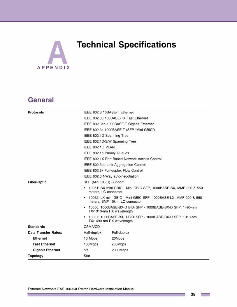
General
Protocols IEEE 802.3 10BASE-T Ethernet
IEEE 802.3u 100BASE-TX Fast Ethernet
IEEE 802.3ab 1000BASE-T Gigabit Ethernet
IEEE 802.3z 1000BASE-T (SFP “Mini GBIC”)
IEEE 802.1D Spanning Tree
IEEE 802.1D/S/W Spanning Tree
IEEE 802.1Q VLAN
IEEE 802.1p Priority Queues
IEEE 802.1X Port Based Network Access Control
IEEE 802.3ad Link Aggregation Control
IEEE 802.3x Full-duplex Flow Control
IEEE 802.3 NWay auto-negotiation
Fiber-Optic SFP (Mini GBIC) Support:
• 10051: SX mini-GBIC - Mini-GBIC SFP, 1000BASE-SX, MMF 220 & 550 meters, LC connector
• 10052: LX mini-GBIC - Mini-GBIC SFP, 1000BASE-LX, MMF 220 & 550 meters, SMF 10km, LC connector
• 10056: 1000BASE-BX-D BiDi SFP - 1000BASE-BX-D SFP, 1490-nm TX/1310-nm RX wavelength
• 10057: 1000BASE-BX-U BiDi SFP - 1000BASE-BX-U SFP, 1310-nm TX/1490-nm RX wavelength
Standards CSMA/CD
Data Transfer Rates:
Ethernet
Fast Ethernet
Gigabit Ethernet
Half-duplex Full-duplex
10 Mbps 20Mbps
100Mbps 200Mbps
n/a 2000Mbps
Topology Star
4t Switch Hardware Installation Manual
35
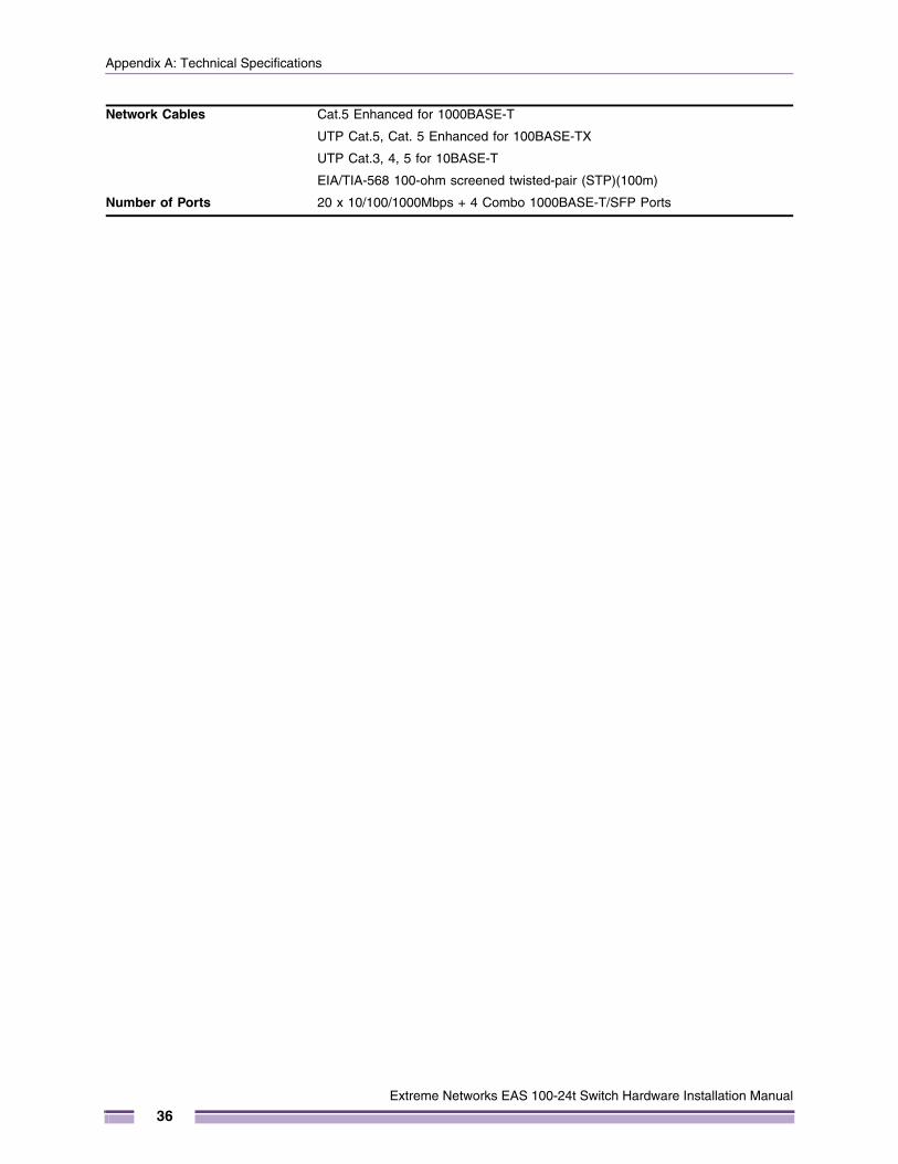
Appendix A: Technical Specifications
Network Cables Cat.5 Enhanced for 1000BASE-T
UTP Cat.5, Cat. 5 Enhanced for 100BASE-TX
UTP Cat.3, 4, 5 for 10BASE-T
EIA/TIA-568 100-ohm screened twisted-pair (STP)(100m)
Number of Ports 20 x 10/100/1000Mbps + 4 Combo 1000BASE-T/SFP Ports
Extreme Networks EAS 100-24t Switch Hardware Installation Manual
36
Physical and Environmental
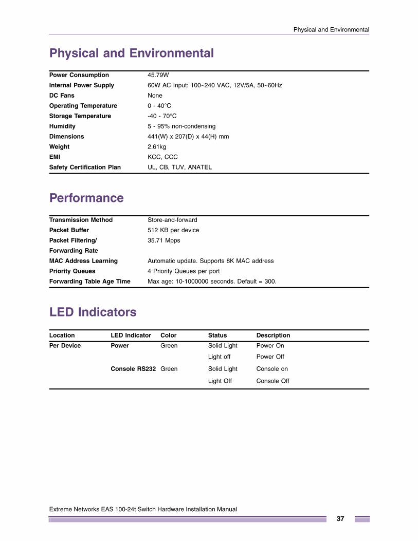
Physical and Environmental
Performance
LED Indicators
Power Consumption 45.79W
Internal Power Supply 60W AC Input: 100~240 VAC, 12V/5A, 50~60Hz
DC Fans None
Operating Temperature 0 - 40°C
Storage Temperature -40 - 70°C
Humidity 5 - 95% non-condensing
Dimensions 441(W) x 207(D) x 44(H) mm
Weight 2.61kg
EMI KCC, CCC
Safety Certification Plan UL, CB, TUV, ANATEL
Transmission Method Store-and-forward
Packet Buffer 512 KB per device
Packet Filtering/
Forwarding Rate
35.71 Mpps
MAC Address Learning Automatic update. Supports 8K MAC address
Priority Queues 4 Priority Queues per port
Forwarding Table Age Time Max age: 10-1000000 seconds. Default = 300.
Location LED Indicator Color Status Description
Per Device Power Green Solid Light Power On
Light off Power Off
Console RS232 Green Solid Light Console on
Light Off Console Off
Extreme Networks EAS 100-24t Switch Hardware Installation Manual
37
Appendix A: Technical Specifications
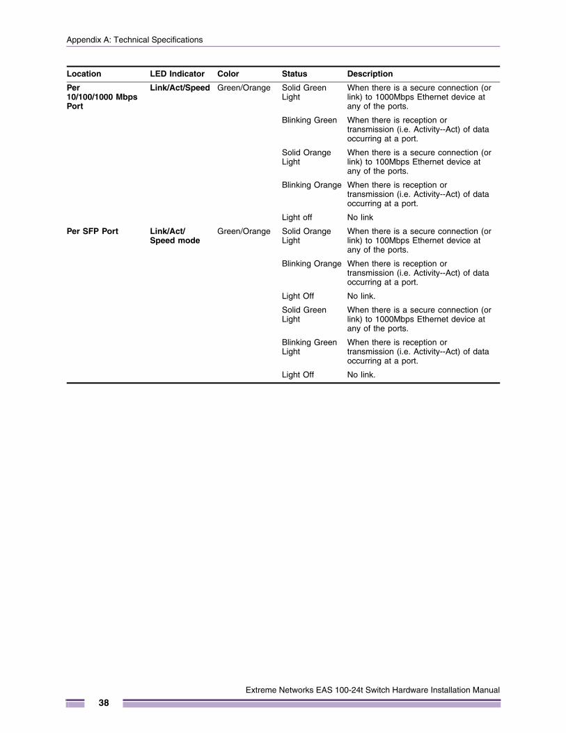
Per 10/100/1000 Mbps Port
Link/Act/Speed Green/Orange Solid Green Light
When there is a secure connection (or link) to 1000Mbps Ethernet device at any of the ports.
Blinking Green When there is reception or transmission (i.e. Activity--Act) of data occurring at a port.
Solid Orange Light
When there is a secure connection (or link) to 100Mbps Ethernet device at any of the ports.
Blinking Orange When there is reception or transmission (i.e. Activity--Act) of data occurring at a port.
Light off No link
Per SFP Port Link/Act/Speed mode
Green/Orange Solid Orange Light
When there is a secure connection (or link) to 100Mbps Ethernet device at any of the ports.
Blinking Orange When there is reception or transmission (i.e. Activity--Act) of data occurring at a port.
Light Off No link.
Solid Green Light
When there is a secure connection (or link) to 1000Mbps Ethernet device at any of the ports.
Blinking Green Light
When there is reception or transmission (i.e. Activity--Act) of data occurring at a port.
Light Off No link.
Location LED Indicator Color Status Description
Extreme Networks EAS 100-24t Switch Hardware Installation Manual
38
B
Extreme Networks EAS 100-2
A P P E N D I X
Cables and Connectors
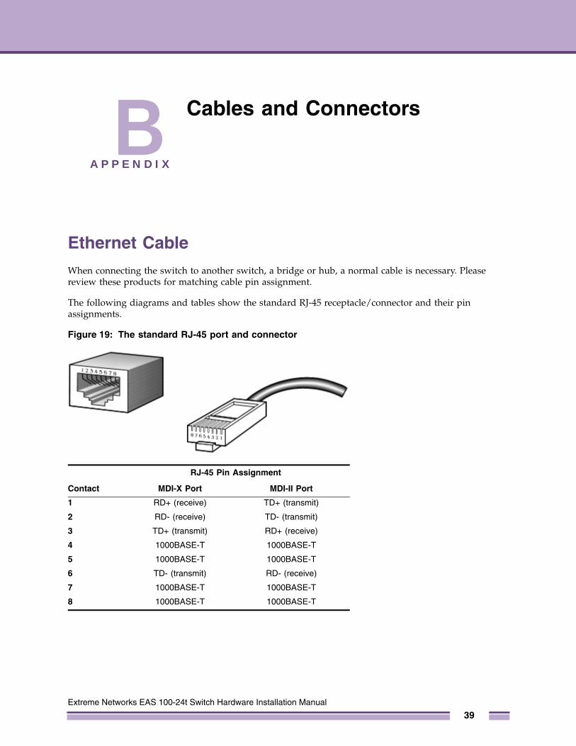
Ethernet CableWhen connecting the switch to another switch, a bridge or hub, a normal cable is necessary. Please review these products for matching cable pin assignment.
The following diagrams and tables show the standard RJ-45 receptacle/connector and their pin assignments.
Figure 19: The standard RJ-45 port and connector
RJ-45 Pin Assignment
Contact MDI-X Port MDI-II Port
1 RD+ (receive) TD+ (transmit)
2 RD- (receive) TD- (transmit)
3 TD+ (transmit) RD+ (receive)
4 1000BASE-T 1000BASE-T
5 1000BASE-T 1000BASE-T
6 TD- (transmit) RD- (receive)
7 1000BASE-T 1000BASE-T
8 1000BASE-T 1000BASE-T
4t Switch Hardware Installation Manual
39
Appendix B: Cables and Connectors
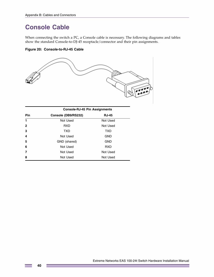
Console CableWhen connecting the switch a PC, a Console cable is necessary. The following diagrams and tables show the standard Console-to-DJ-45 receptacle/connector and their pin assignments.
Figure 20: Console-to-RJ-45 Cable
Console-RJ-45 Pin Assignments
Pin Console (DB9/RS232) RJ-45
1 Not Used Not Used
2 RXD Not Used
3 TXD TXD
4 Not Used GND
5 GND (shared) GND
6 Not Used RXD
7 Not Used Not Used
8 Not Used Not Used
Extreme Networks EAS 100-24t Switch Hardware Installation Manual
40