Embed Size (px)
Citation preview

Western University Western University
Scholarship@Western Scholarship@Western
Electronic Thesis and Dissertation Repository
11-6-2019 3:00 PM
Extrusion-based 3D Printing of Macro/Microstructures for Extrusion-based 3D Printing of Macro/Microstructures for
Advanced Lithium/Sodium Batteries Advanced Lithium/Sodium Batteries
Jiwei Wang, The University of Western Ontario
Supervisor: Tsun-Kong Sham, The University of Western Ontario
Co-Supervisor: Xueliang Sun, The University of Western Ontario
A thesis submitted in partial fulfillment of the requirements for the Doctor of Philosophy degree
in Chemistry
© Jiwei Wang 2019
Follow this and additional works at: https://ir.lib.uwo.ca/etd
Recommended Citation Recommended Citation Wang, Jiwei, "Extrusion-based 3D Printing of Macro/Microstructures for Advanced Lithium/Sodium Batteries" (2019). Electronic Thesis and Dissertation Repository. 6775. https://ir.lib.uwo.ca/etd/6775
This Dissertation/Thesis is brought to you for free and open access by Scholarship@Western. It has been accepted for inclusion in Electronic Thesis and Dissertation Repository by an authorized administrator of Scholarship@Western. For more information, please contact [email protected].

II
Abstract
With the development of electronics and electric vehicles, high-performance batteries with high
energy density, high safety, and aesthetic diversity are greatly needed as dominating power sources.
However, the electrodes and electrolytes fabricated with traditional techniques have limited form
factors, mechanical flexibility, and poor performance. Extrusion-type 3D printing techniques have
thus been applied to fabricate 3D batteries with high performance since 3D printing techniques
have great advantages in the fabrication of complex 3D structures and geometric shapes from
various materials. The research in this thesis aims at fabricating high-performance Li/Na batteries
via 3D printing of advanced electrodes and solid electrolytes.
Firstly, an extrusion-type 3D printing method was applied for fabricating 3D-patterned ultrathick
LiFePO4 electrodes. The designed unique 3D architectures could greatly improve the electron/ion
transport even within the thick electrodes. We also demonstrated the 3D printing of patterned
silicon (Si) anodes with vertically aligned and multi-scaled porous structures for achieving high-
areal capacity LIBs by using a low-cost aqueous-based ink.
Besides fabricating electrodes, we also fabricated LAGP (Li1.5Al0.5Ge1.5P3O12) thin solid
electrolytes through an extrusion-type 3D printing approach. The printed thin solid electrolyte with
short Li+ transport path can increase the energy density and power density of a solid battery.
An extrusion-based 3D printing approach was also developed to construct a high-performance
sodium metal battery (SMB) consisting of a printed Na@rGO/CNT anode and a printed O3-
NaCu1/9Ni2/9Fe3/9Mn3/9O2 (denoted as NCNFM) cathode. The 3D-printed Na@rGO/CNT anode
possesses multiple porosities, which could provide abundant active reaction sites and enable fast
Na+ transport. Moreover, the resultant 3D structured Na@rGO/CNT can effectively suppress the
Na dendrite growth by decreasing the local current density and releasing the huge volume change
of Na during cycling. On the other hand, the 3D-printed micro-structured NNCFM cathode
composed of interconnected CNTs and porous polymer framework can enable fast electron and
ion transport as well as facilitated electrolyte penetration within the whole electrode.
III
To further increase the energy density of a sodium-ion battery, we developed high-voltage layered
P2-Na2/3Ni1/3Mn2/3O2 (NMO) cathodes. By applying ALD AlPO4 coating layer on the NMO
particles, the reduction of Mn was suppressed upon cycling, which could improve the structural
stability of the cathode. This high-voltage cathode can be used as materials for 3D printing of high
energy density sodium-ion battery in the future.
In summary, this thesis has successfully developed various printable inks and designed unique 3D
architectures via an advanced extrusion-type 3D printing technique for achieving high-
performance Li/Na batteries.
Keywords
High energy density, Extrusion-type 3D printing, 3D batteries, Solid electrolyte, 3D-patterned
LiFePO4, Patterned silicon, LAGP thin electrolyte, Short Li+ transport path, Sodium metal battery
(SMB), Sodium dendrite growth, High-voltage layered cathodes, Atomic layer deposition (ALD),
Aluminum Phosphate (AlPO4)
Lay Summary
Extrusion-type 3D printing is a technique that extrudes a paste-like ink with shear-thinning
behavior through a nozzle to build 3D architectures in a layer-by-layer way. After extrusion, the
3D architectures usually become solidification through the evaporation of solvents, chemical
changes (cross-linking) or freeze-drying.
Rechargeable batteries have attracted significant attention due to their high energy density and
power density as well as pollution-free operation. However, traditional manufacturing methods are
hard to fabricate thick electrodes with fast electron/ion transport due to the planar structure
limitations. Moreover, electrodes and electrolytes fabricated by traditional techniques have limited
form factors and mechanical flexibility. Extrusion-type 3D printing techniques thus have been
applied to design various 3D architectures for achieving high-performance Li/Na batteries.

IV
Co-Authorship Statement
Chapter 3
Title: Toward High Areal Energy and Power Density Electrode for Li-Ion Batteries via
Optimized 3D Printing Approach
The final version of this manuscript has been published in ACS Appl. Mater. Interfaces, 2018,
10, 39794-39801
X. Sun, T.K. Sham, and X. Sun directed the project. J. Wang conceived the idea, designed
the experiments and wrote the manuscript. Q. Sun gave some suggestions for the
experiments and manuscript. X. Gao helped with the freeze-drying. W. Li and C. Wang
helped with SEM characterization. F. Holness and A. Price gave some suggestions on the
3D printing technique. M. Zheng gave some suggestions for the writing. R. Li helped with
purchasing chemicals and characterizations. All authors discussed the results and
commented on the manuscript.
Chapter 4
Title: 3D Printing of Vertically Aligned and Patternable Silicon Anodes for High Areal Capacity
Li-Ion Batteries
The final version of this manuscript is to be submitted for publishing
X. Sun, T.K. Sham, and X. Sun directed the project. J. Wang conceived the idea, designed
the experiments and wrote the manuscript. Q. Sun gave some suggestions for the
experiments and manuscript. X. Gao helped with the freeze-drying. W. Li and Y. Sun
helped with SEM characterization. X. Lin and J. Liang helped with the Raman
measurements. M. Zheng gave some suggestions for the writing. R. Li helped with
purchasing chemicals and characterizations. All authors discussed the results and
commented on the manuscript.

V
Chapter 5
Title: 3D Printing of Shape-Versatile and Thin Solid Electrolyte for High-Performance Solid-State
Li-Metal Batteries
The final version of this manuscript is to be submitted for publishing
X. Sun, T.K. Sham, and X. Sun directed the project. J. Wang conceived the idea, designed
the experiments and wrote the manuscript. Q. Sun gave some suggestions for the
experiments and manuscript. C. Zhao prepared the gel polymer electrolyte. J. Luo provided
the cathode electrodes. J. Liang helped with the XRD measurements. C. Wang and Y. Sun
helped on the ionic conductivity testing. M. Zheng gave some suggestions on the
manuscript writing. R. Li helped with purchasing chemicals and characterizations. All
authors discussed the results and commented on the manuscript.
Chapter 6
Title: 3D Printing of High-Performance Na-Metal Batteries
The final version of this manuscript is to be submitted for publishing
X. Sun, T.K. Sham, and X. Sun directed the project. J. Wang conceived the idea and
designed the experiments and wrote the manuscript. Q. Sun and C. Wang gave some
suggestions for the experiments and manuscript. W. Li and X. Lin helped with the SEM
measurements. X. Gao helped with the freeze-drying. J. Luo gave some suggestions on the
manuscript writing. R. Li helped with purchasing chemicals and characterizations. All
authors discussed the results and commented on the manuscript.
Chapter 7
Title: Nanoscale Surface Modification of High-Voltage Layered Sodium Cathode via Atomic
Layer Deposition of Aluminum Phosphate with Enhanced Cycle Performance

VI
The final version of this manuscript is to be submitted for publishing
X. Sun, T.K. Sham, and X. Sun directed the project. J. Wang conceived the idea and
designed the experiments and wrote the manuscript. Q. Sun gave some suggestions for the
experiments and manuscript. C. Wang and X. Gao helped with the SEM measurements. B.
Wang helped with the ALD coating experiments. X. Lin and C. Wang helped with the XRD
measurements. Y. Sun gave some suggestions on the manuscript writing. R. Li helped with
purchasing chemicals and characterizations. All authors discussed the results and
commented on the manuscript.

VII
Acknowledgements
First of all, I would like to express my sincerest appreciation to my supervisors, Prof. Tsun-
Kong Sham, and Prof. Xueliang (Andy) Sun. It is my great honor for me to have a valuable
opportunity working with such two great researchers. Prof. Sun’s dedication to work, his
passions to science, and his patience have greatly inspired me. Prof. Sham’s profound
knowledge, creative ideas, and kindness have impressed me a lot throughout my graduate
study. Without their unconditional support and guidance, I would not have been completed
my Ph.D. study.
Second, I would like to thank Mrs. Ruying Li, who is the wife of Dr. Sun and a research
engineer in Dr. Sun’s lab. She has dedicated many efforts on the lab management. I am
truly grateful for her help in training me the experimental techniques and her care on my
research and life.
I would also like to thank my past and present group members that I have worked with
during the past four years. I would especially like to thank Dr. Qian Sun who is always
patient and ready to answer any questions and provide helpful instructions on my research.
I would also like to express my appreciations to Mr. Changhong Wang and Mr. Yipeng Sun
for helping me a lot in both my research and daily life. I would also like to thank other
group members: Dr, Yun-Mui You, Dr. Zhiqiang Wang, Dr. Xiao Xuan Guo, Dr. Lijia Liu,
Dr. Jun Li, Dr. Mohammad Norouzi Banis, Dr. Madalena Sophia Kozachuk, Dr. Weihan
Li, Dr. Xia Li, Dr. Lei Zhang, Dr. Jianwen Liang, Dr. Xiaona Li, Dr. Changtai Zhao, Dr.
Xulei Sui, Dr. Yang Zhao, Dr. Biqiong Wang, Dr. Biwei Xiao, Dr. Wei Xiao, Dr. Niancai
Cheng, Dr. Yulong Liu, Dr. Karthikeyan Kaliyappan, Dr. Andrew Lushington, Dr. Dawei
Wang, Dr. Zhongxin Song, Mr. Jiatang Chen, Ms. Fei Sun, Mr. Heng Xiang, Ms. Xiaoting
Lin, Mr. Jianneng Liang, Mr. Junjie Li, Mr. Feipeng Zhao, Ms. Xuejie Gao, Ms. Jing Luo,
Ms. Minsi Li, Mr. Keegan Adair, Mr. Sixu Deng, Ms. Shumin Zhang, Mr. Xuchun Wang,
and Ms. Lu Yao. It has been a great pleasure working with you.

VIII
I would also like to thank the funding support from the Natural Science and Engineering
Research Council of Canada (NSERC), the Canada Research Chair Program (CRC), the
Canada Foundation for Innovation (CFI), Jiangsu Key Laboratory for Carbon-Based
Functional Materials and Devices and Collaborative Innovation Center of Suzhou Nano
Science & Technology, Canadian Light Source (CLS) at the University of Saskatchewan,
the Canadian Institute of Health Research (CIHR), and the University of Western Ontario
(UWO). I acknowledge the support of a travel grant by CLS.
I would also like to thank my collaborators. Dr. Aaron David Price, Mr. Frederick Benjamin
Holness at UWO, Dr. Xuhui Sun and Mr. Kun Feng at Soochow University.
Lastly, I have to thank my mother and my older sisters in China for all of their support and
love throughout my graduate study. It was not easy to start a new life and graduate study
here in Canada. I would not do it without your encouragement and love.
IX
Table of Contents
Abstract ........................................................................................................................................... II
Co-Authorship Statement.............................................................................................................. IV
Acknowledgements ...................................................................................................................... VII
Table of Contents .......................................................................................................................... IX
List of Figures ............................................................................................................................ XIV
List of Abbreviations ............................................................................................................... XXIII
Chapter 1 ......................................................................................................................................... 1
1.1 General introduction ............................................................................................................. 1
1.2 3D printing of electrodes for energy storage ........................................................................ 6
1.2.1 3D-printed electrodes for Li-ion batteries...................................................................... 6
1.2.2 3D-printed electrodes for Li-S battery ........................................................................... 8
1.2.3 3D-printed electrodes for Li-O2/CO2 batteries ............................................................ 10
1.2.4 3D-printed electrodes for Na-ion batteries .................................................................. 12
1.2.5 3D-printed electrodes for supercapacitors ................................................................... 15
1.3 3D printing of electrolytes and separator membranes for energy storage .......................... 17
1.3.1 3D printing of polymer separator for Li-metal batteries .............................................. 17
1.3.2 3D printing of Solid-State Electrolyte ......................................................................... 18
1.3.3 3D printing of Hybrid Solid-State Electrolyte ............................................................. 19
1.4 All 3D-Printed Energy Storage Devices ............................................................................. 21
1.4.1 All 3D-printed LIBs/LMBs.......................................................................................... 21
1.4.2 All 3D-Printed Supercapacitors ................................................................................... 24
1.4.3 All 3D-printed Zn-based Batteries ............................................................................... 25
1.5 Thesis objectives ................................................................................................................. 27
1.6 Thesis outline ...................................................................................................................... 28
X
1.7 References ........................................................................................................................... 30
Chapter 2 ....................................................................................................................................... 54
2 Experimental Methods and Characterization Techniques ................................................. 54
2.1 Experimental methods .................................................................................................... 54
2.1.1 3D printing of free-standing patterned LiFePO4 (LFP) thick electrodes ..................... 54
2.1.2 3D Printing of Patternable Silicon Electrodes ............................................................. 56
2.1.3 3D Printing of Thin Solid-State Electrolyte LAGP (Li1.5Al0.5Ge1.5P3O12) .................. 57
2.1.4 3D Printing of GO/CNT skeleton ................................................................................ 58
2.1.5 Fabrication of 3D Na@rGO/CNT composite electrode .............................................. 58
2.1.6 Synthesis of O3-NaCu1/9Ni2/9Fe3/9Mn3/9O2 by Solid-State Reaction Method ............. 58
2.1.7 3D Printing of O3-NCNFM skeleton ........................................................................... 59
2.1.8 Synthesis of P2-Na2/3Ni1/3Mn2/3O2 (NMO)by Solid-State Reaction Method............... 60
2.1.9 Atomic layer deposition coating of AlPO4 on P2-Na2/3Ni1/3Mn2/3O2 Cathode ............ 60
2.2 Characterization Techniques ............................................................................................... 61
2.2.1 Physical Characterization methods .............................................................................. 61
2.2.2 Electrochemical measurements .................................................................................... 65
Chapter 3 ....................................................................................................................................... 68
3 Toward High Areal Energy and Power Density Electrode for Li-Ion Batteries via Optimized
3D Printing Approach ................................................................................................................... 68
3.1 Introduction ......................................................................................................................... 69
3.2 Experiment Section ............................................................................................................. 71
3.2.1 Preparation of LFP ink ................................................................................................. 71
3.2.2 3D printing process ...................................................................................................... 71
3.2.3 Materials characterizations .......................................................................................... 71
3.2.4 Electrochemical measurements .................................................................................... 71
3.3 Results and Discussion ....................................................................................................... 72
XI
3.3.1 Morphology and Structural Characterization............................................................... 72
3.3.2 Electrochemical Characterization ................................................................................ 75
3.4 Conclusion .......................................................................................................................... 80
Acknowledgements ................................................................................................................... 81
3.5 References ........................................................................................................................... 81
Chapter 4 ....................................................................................................................................... 91
4 3D Printing of Vertically Aligned and Patternable Silicon Anodes for High Areal Capacity
Li-Ion Batteries ............................................................................................................................. 91
4.1 Introduction ......................................................................................................................... 92
4.2 Experimental Section .......................................................................................................... 93
4.2.1 Si-SA Ink Preparation .................................................................................................. 93
4.2.2 3D Printing Process...................................................................................................... 94
4.2.3 Materials characterizations .......................................................................................... 94
4.2.4 Electrochemical Measurements ................................................................................... 94
4.3 Results and Discussion ....................................................................................................... 94
4.3.1 Morphology and Structure Characterization ................................................................ 94
4.3.2 Electrochemical Characterization ................................................................................ 97
4.3.3 Post-cycled Electrode Morphology Characterization ................................................ 100
4.4 Conclusion ........................................................................................................................ 102
Acknowledgements ................................................................................................................. 102
4.5 References ......................................................................................................................... 103
Chapter 5 ..................................................................................................................................... 114
5 3D Printing of Shape-Versatile and Thin Solid Electrolyte for High-Performance Solid- State
Li-Metal Batteries ....................................................................................................................... 114
5.1 Introduction ....................................................................................................................... 115
5.2 Experimental Section ........................................................................................................ 116

XII
5.2.1 Ink Preparation ........................................................................................................... 116
5.2.2 3D printing process .................................................................................................... 117
5.2.3 Materials Characterizations ....................................................................................... 117
5.2.4 Electrochemical Measurements ................................................................................. 117
5.3 Results and Discussion ..................................................................................................... 118
5.3.1 Morphology and Structure Characterization .............................................................. 118
5.3.2 Electrochemical Characterization .............................................................................. 121
5.4 Conclusion ........................................................................................................................ 124
Acknowledgements ................................................................................................................. 124
5.5 References ......................................................................................................................... 124
Chapter 6 ..................................................................................................................................... 134
6 3D Printing of High-Performance Sodium Metal Batteries ..................................................... 134
6.1 Introduction ....................................................................................................................... 135
6.2 Experimental Section ........................................................................................................ 137
6.2.1 Material synthesis ...................................................................................................... 137
6.2.2 Preparation of GO/CNT ink ....................................................................................... 137
6.2.3 Preparation of NCNFM ink ....................................................................................... 137
6.2.4 3D printing process .................................................................................................... 138
6.2.5 Fabrication of Na@rGO/CNT composite electrodes ................................................. 138
6.2.6 Materials Characterizations: ...................................................................................... 138
6.2.7 Electrochemical Measurements: ................................................................................ 138
6.3 Results and Discussions .................................................................................................... 139
6.3.1 Morphology and Structure Characterization .............................................................. 139
6.3.2 Electrochemical Characterization .............................................................................. 143
6.4 Conclusions ....................................................................................................................... 146

XIII
Acknowledgements ................................................................................................................. 146
6.5 References ......................................................................................................................... 147
Chapter 7 ..................................................................................................................................... 154
7 Nanoscale Surface Modification of High-Voltage Layered Sodium Cathode via Atomic Layer
Deposition of Aluminum Phosphate with Enhanced Cycle Performance .................................. 154
7.1 Introduction ....................................................................................................................... 155
7.2 Experimental Section ........................................................................................................ 157
7.2.1 Preparation of P2-Na2/3Ni1/3Mn2/3O2.......................................................................... 157
7.2.2 Atomic layer deposition of AlPO4 on P2-Na2/3Ni1/3Mn2/3O2 ..................................... 157
7.2.3 Materials characterization .......................................................................................... 157
7.2.4 Electrochemical performance measurements ............................................................ 158
7.3 Results and Discussions ........................................................................................................ 158
7.3.1 Morphology and Structure Characterization .................................................................. 158
7.3.2 Electrochemical Characterization .............................................................................. 162
7.3.3 Post-cycling Characterization .................................................................................... 167
7.4 Conclusions ....................................................................................................................... 168
Acknowledgements ................................................................................................................. 168
7.5 References ......................................................................................................................... 169
Chapter 8 ..................................................................................................................................... 179
8 Summary and Future Work ...................................................................................................... 179
8.1 Conclusions ....................................................................................................................... 179
8.2 Future Work ...................................................................................................................... 181
Appendices .................................................................................................................................. 184
Curriculum Vitae ........................................................................................................................ 185

XIV
List of Figures
Figure 1.1.1 Schematic of the FDM printing system……………………………………………...2
Figure 1.1.2 Schematic of the SLA printing system……………………………………………....3
Figure 1.1.3 Schematic of the SLS printing system……………………………………………….4
Figure 1.1.4 Schematic of the extrusion-type DIW printing system………………………………5
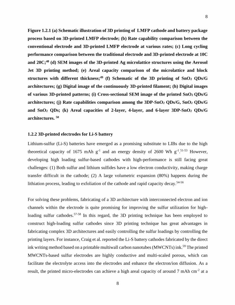
Figure 1.2.1 (a) Schematic illustration of 3D printing of LMFP cathode and battery package
process based on 3D-printed LMFP electrode; (b) Rate capability comparison between the
conventional electrode and 3D-printed LMFP electrode at various rates; (c) Long cycling
performance comparison between the traditional electrode and 3D-printed electrode at 10C and
20C; (d) SEM images of the 3D-printed Ag microlattice structures using the Aerosol Jet 3D
printing method; (e) Areal capacity comparison of the microlattice and block structures with
different thickness; (f) Schematic of the 3D printing of SnO2 QDs/G architectures; (g) Digital
image of the continuously 3D-printed filament; (h) Digital images of various 3D-printed patterns;
(i) Cross-sectional SEM image of the printed SnO2 QDs/G architectures; (j) Rate capabilities
comparison among the 3DP-SnO2 QDs/G, SnO2 QDs/G and SnO2 QDs; (k) Areal capacities of 2-
layer, 4-layer, and 6-layer 3DP-SnO2 QDs/G architectures………………………………………..8
Figure 1.2.2 (a) Schematic illustration of 3D printing sulfur copolymer-graphene (3DP-pSG)
architectures; (b) Top-view SEM image of the 3D architecture, showing periodic macropores; (c)
Cross-sectional SEM image of the 3D architecture; (d) Cycle performances of 3DP-pSG and 3DP-
SG at 50 mA g-1; (e) Schematic demonstration of the 3D printing of S/BP 2000 thick cathodes; (f-
h) SEM images of the 3D electrode at different magnifications from top view; (i) Cycling
performance of the 3DP-FDE electrodes with a sulfur loading of 5.5 mg cm-2 at various rates…..10
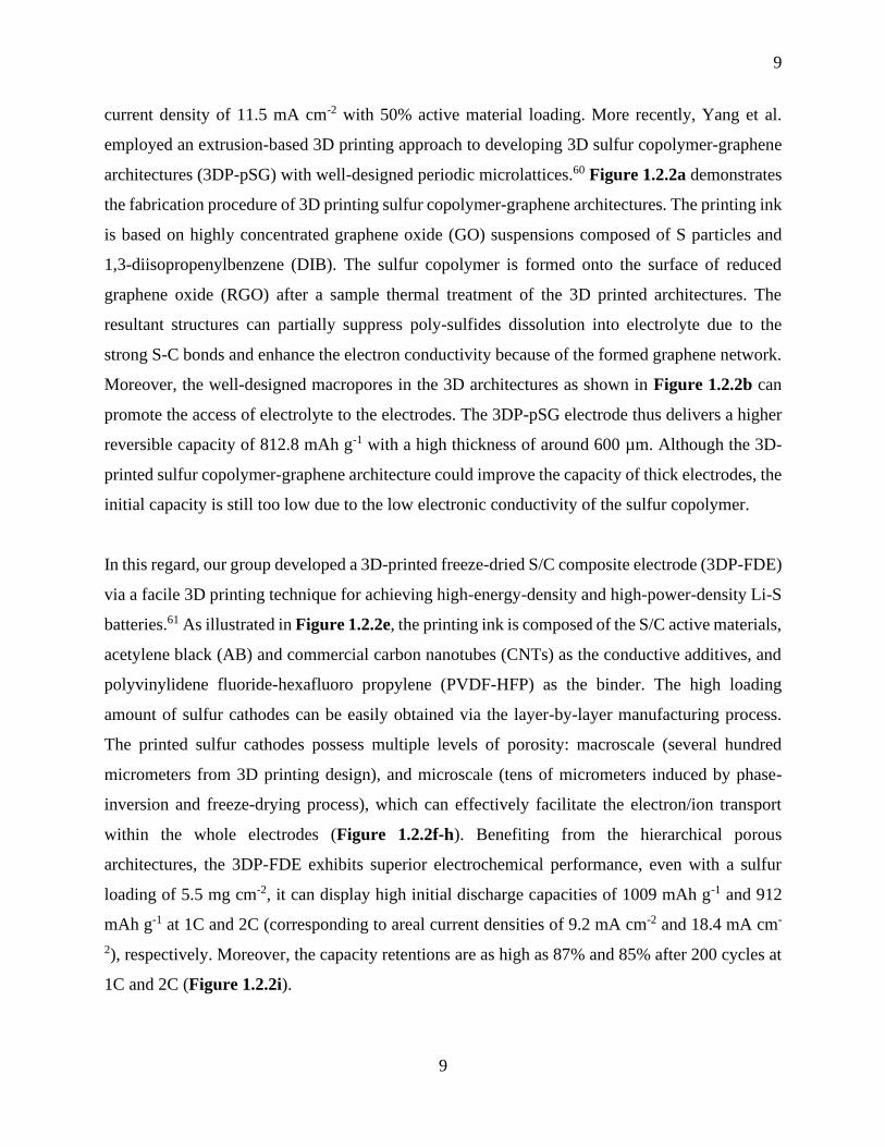
Figure 1.2.3 (a) Digital image showing the process of printing complex 3D architectures line-by-
line; (b) Digital image of the printed hGO mesh after freeze-drying; (c) Optical image of the printed
freeze-dried hGO mesh. Scale bar is 500 µm. (d) Cross-sectional SEM image of the porous 3D
printed hGO mesh structure. Scale bar is 50 µm. (e) Deep discharge performance of the printed r-
XV
hGO mesh; (f) and (h) Optical images, (g) and (i) SEM image of 3DP-Co-MOF and 3DP-NC-Co,
respectively; (j) First discharge curves of the marked cathodes; (k) Rate capability of 3DP-NC-Co
with different current densities; (i) Schematic of the synthesis of Ni-rGO framework; (m) Digital
images of the GO and Ni-rGO frameworks; (n) and (o) SEM images of the Ni-rGO; (p) Cycling
performance (q) Discharge/charge curves of the Ni-rGO at various current densities with a limit
capacity.………………………………………………………………………………………….12
Figure 1.2.4 Printed SIBs electrodes via 3D and inkjet printing. (a) Schematic illustration of 3D-
printing GO-NVP hierarchical porous frameworks; (b, c) SEM images of 3D-printed GO-NVP
architectures at different magnifications; (d) Cycle performance at 2C, and (e) rate capability of
the 3D-printed rGO-NVP electrodes; Schematic of (f) the inkjet printing setup, and (g, h) the
printing process of the ATM-GO droplets in a raster fashion, ice template formation (i) during
printing, and the resulting ATM-GO aerogel after freeze-drying (j); (k) An example macrostructure
of the 3D printed ATM-GO aerogel after freeze-drying and the resulting MoS2-rGO aerogel after
thermal reduction; (l) High-magnification SEM image of the MoS2-rGO printed on a Ni foam; (m)
Rate performance of the MoS2-rGO aerogel at various current densities…………………………14
Figure 1.2.5 (a) Schematic illustration of 3D printing graphene aerogel micro-lattice. (b)
Gravimetric capacitance and capacitive retention calculated as a function of current density. Inset:
schematic demonstration of the 3S-GCA SSC. (c) Cycling performance measured at a scan rate of
200 mV/s for 10 000 cycles. Inset shows the first and last cyclic voltammograms collected during
the cycling stability test. (d) Comparison of the 3D-GCA SSC with reported values in terms of
gravimetric energy densities and power densities. (e) Schematic of 3D printing r-GO micro-lattice
based on GO-CaCl2 ink. (f) Optical image of the printed GO micro-lattice. (g) SEM image of the
printed GO micro-lattice. (h-j) Electrochemical performance of the 3D printed r-GO micro-lattice.
(k) Schematic of fabrication of a 3D printed graphene aerogel/MnO2 electrode. (l) SEM image of
the 3D printed graphene aerogel/MnO2 electrode. (m) Gravimetric capacitances and volumetric
capacitances of the 3D G/MnO2 electrodes with different mass loading of MnO2. (n) Areal
capacitances of 3D G/MnO2 and non-3D printed G/MnO2 electrodes at different current
densities…………………………………………………………………………………………..16

XVI
Figure 1.3.1 (a) Schematic illustration of the 3D printing machine and BN in PVDF-HFP separator;
(b) Optical images of the 3D-printed BN/PVDF-HFP separator at different stages during the
printing process; (c-e) SEM images of the 3D-BN/PVDF-HFP separator; (f-i) Cycling
performance of the Li-Li symmetric cells at a current density of 1 mA cm-2……………………18
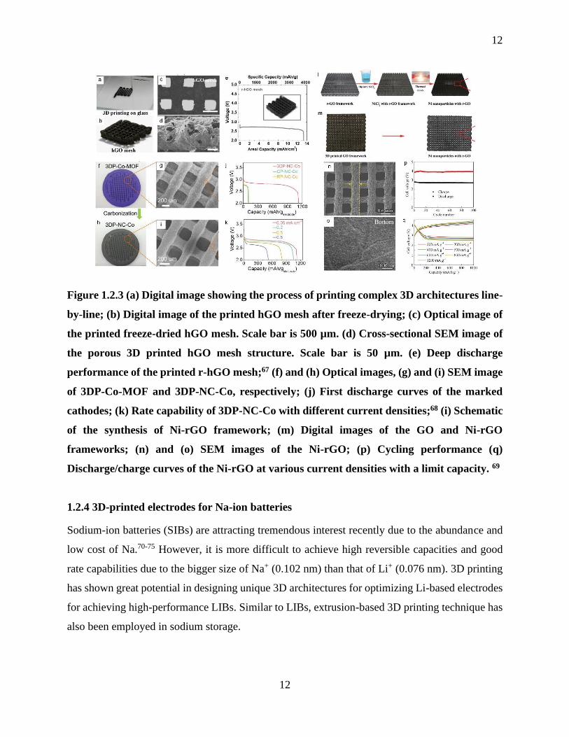
Figure 1.3.2 (a) Schematic illustration of the process of 3D printing LLZO structures and electrode
infiltration into the 3D LLZO structures; (b) Schematic of Li melted into the pores of the 3D-
printed LLZO grids on an LLZO substrate; (c) Cross-sectional SEM of 3D-printed LLZO/Li metal
interface; (d) Voltage profile of the Li/3D-Printed LLZO/Li metal symmetric cell at various current
densities…………………………………………………………………………………………..19
Figure 1.3.3 (a) Schematic of the fabrication process of 3D-printed hybrid electrolytes.
Corresponding SEM images of each synthesis stage of the 3D LAGP-epoxy hybrid electrolytes
are listed below each schematic; (b) Galvanostatic cycling of Li-Li cells with LAGP pellet and
gyroid LAGP-epoxy electrolytes cycled at a current density of 0.7 mA cm-2; (c) Schematic of the
elevated-temperature direct ink writing system and solid-electrolyte ink fabrication process; (d-g)
Electrochemical impedance spectroscopy (EIS) of the hybrid solid-state electrolyte…………….21
Figure 1.4.1 3D-printed interdigitated Li micro-batteries. (a) Schematic illustration of 3D-printed
interdigitated micro-battery architectures on the gold current collector with printed Li4Ti5O12 (LTO)
and LiFePO4 (LFP) as the anode and cathode, followed by packaging. (b) SEM images of printed
and annealed 16-layer interdigitated LTO-LFP electrode architectures, respectively. (c) Optical
image of 3D-printed micro-battery composed of LTO-LFP electrodes after packaging. (d)
Schematic of the 3D-printed interdigitated electrodes with LTO/GO and LFP/GO as the ink for
anode and cathode electrodes, respectively. The gel polymer composite ink is injected in the
channel between the annealed electrodes. (e) Digital image of the interdigitated electrodes. (f)
Cycling stability of the 3D-printed full cell. (g) Charge/discharge profiles of the 3D-printed full
cell. (h, i) Digital images of a miniaturized version of the 3D-printed electrodes. (j) Digital image
of the 3D-printed electrodes arrays. (k) Schematic illustration of the CNF ink derived from trees
and 3D-printed LMBs fabricated by printing c-CNF/LFP cathode and c-CNF/Li anode. (i-n)
Photographs of a CNF scaffold after freeze-drying and before carbonization, c-CNF scaffold after
carbonization, and c-CNF/Li electrode with designed 3D structure. (o) Cycling performance
XVII
comparison of c-CNF/Li and Li foil in a symmetric cell at a current density of 5 mA cm-2 with
areal capacity fixed at 2.5 mAh cm-2……………………………………………………………..23
Figure 1.4.2 (a) Schematic illustration of 3D printing of an interdigitated asymmetric MSC on the
gold current collector. The gel-like electrolyte was injected into the channels between the anode
and cathode. (b) SEM image of 3D-printed 4-layer electrodes. (c) Areal and volumetric
capacitances of the 3D printed asymmetric MSC. (d) Comparison of the 3D printed MSC and other
reported asymmetric interdigitated MSCs. (e) Schematic of 3D printing of the FASC device. (f)
Digital image of the wet fiber during the printing process. (g, h) SEM images of the printed fiber
electrode and assembled FASC device. (i) Schematic of the assembled FASCs device. (j) CV of
the assembled device measured at different voltage window. (k) Capacitance retention of the
FASC devices after repeated bending…………………………………………………………….25
Figure 1.4.3 (a) Schematic illustration of the fabrication process of the Ag-Zn cell through the
screen printing method and the prototype of the Ag-Zn cell on temporary transfer tattoo support.
(b) Flow diagram showing the fabrication steps for the mesh-embedded printed MnO2 cathode and
Zn anode with a printed silver current collector, and the optical image of a flexible Zn-MnO2
battery laminated inside a polyethylene pouch. (c) Schematic of screen printing of a Zn-Ag2O
battery on a stretchable textile and corresponding digital photos of sealed battery with different
stretched stages. (d) Schematic illustration of fabrication process of the printed Zn-Ag2O battery
and 1mm printed Zn anode compared to a commercially packaged device and an unpackaged
chip……………………………………………………………………………………………….27
Figure 2.1 ARM 310 Thinky Mixer for ink preparation…………………………………………54
Figure 2.2 Fused filament fabrication (FFF) DeltaMaker 3D printer …………………………...55
Figure 2.3 Freeze-Drier for drying the printed structures………………………………………..56
Figure 2.4 Thermal furnace for heating the O3-NCNFM precursor pellet………………………59
Figure 2.5 Ball-milling machine used for preparing P2-Na2/3Ni1/3Mn2/3O2 precursor…………..60

XVIII
Figure 2.6 Savannah 100 ALD system (Cambridge Nanotech, USA)…………………………..61
Figure 2.7 High-Resolution Field-Emission SEM (Hitachi 4800)………………………………62
Figure 2.8 X-ray Diffraction System (Bruker D8 Advance)…………………………………….63
Figure 2.9 Raman Spectroscopy System (HORIBA Scientific LabRAM HR)………………….63
Figure 2.10 High-Resolution Field-Emission TEM (FEI Quanta FRG 200F)…………………..64
Figure 2.11 Nicolet 6700 FTIR spectrometer……………………………………………………64
Figure 2.12 Schematic of beamlines at Canadian Light Source…………………………………65
Figure 2.13 Argon-filled glove box for coin-cell assembly……………………………………...66
Figure 2.14 Digital photo of the LAND battery testing system………………………………….67
Figure 2.15 Photo of the Bio-Logic multichannel potentiostat 3/Z (VMP3)…………………….67
Figure 3.1 a) Schematic illustration of 3D-printed self-supported LFP electrodes, and b) Optical
images of 3D-printed LFP structure with various patterns………………………………………72
Figure 3.2 Schematic and SEM images of three types of 3D-printed LFP electrodes. a) Schematic
illustration and b, c, and d) SEM images of 3D-printed circle-grid pattern LFP electrode. e)
Schematic illustration and f, g, and h) SEM images of 3D-printed circle-ring pattern LFP electrode.
i) Schematic illustration and j, k, and l) SEM images of 3D-printed circle-line pattern LFP
electrode………………………………………………………………………………………….74
Figure 3.3 Electrochemical performance of the three types of 3D-printed LFP electrodes. a)
Comparison of rate performance of the three types of LFP electrodes. Charge-discharge voltage
curves of b) 3D-printed grid pattern, c) 3D-printed ring pattern and d) 3D-printed line pattern LFP
electrodes at various rates. e) Cycling performance of the three types of LFP electrodes at 1C with
the first six cycles activated at 0.1 C. ……………………………………………………………..77
XIX
Figure 3.4 a) Practical and theoretical thickness of the 3D-printed electrodes as a function of the
printing layer number (inset: optical images of 3D-printed electrodes with different printing layers).
b) Comparison of the areal capacity of the LFP electrodes with different layer numbers. c)
Charge/discharge profiles of the LFP electrodes with different layer numbers. d) Comparison of
power density and energy density of this work with previously reported values………………….79
Figure 3.5 Schematic illustration of the comparison between ultra-thick a) traditional electrodes
and b) 3D electrodes……………………………………………………………………………..80
Figure 4.1. Fabrication process and material characterization of the 3D-VLMP Si electrode. (a)
Schematic illustration of 3D printing of vertically aligned silicon electrodes with multiple levels
of porosities. (b to e) SEM images of the 3D-VLMP Si electrodes under different magnifications;
(f and g) SEM image and corresponding EDX mappings of the 3D-VLMP Si electrode…………95
Figure 4.2 Electrochemical performances comparison of the Si electrodes with different structures.
(a) Areal capacity vs. cycle number at a current of 1 Ag-1 for 60 cycles; (b and c) Charge-discharge
profiles of the various Si electrodes at their 60th cycle; (d) Rate capability of the 3D-VLMP and
Flat-NVLMP Si electrodes at various current densities from 0.5 to 5 mA cm-2; (e and f) Charge-
discharge profiles of the 3D-VLMP and Flat-NVLMP Si electrodes at various current densities
from 0.5 to 5 mA cm-2; (g) The capacity retentions of the 3D-VLMP and Flat-NVLMP Si
electrodes at a current density of 2 Ag-1, along with the Coulombic efficiency of the 3D-VLMP Si
electrode over 300 cycles………………………………………………………………………...97
Figure 4.3 Performance metrics for 3D-VLMP Si electrodes with high areal mass loading.
(a) Schematic illustration of the 3D-printed VLMP Si electrodes with different thickness and mass
loadings; (b) Comparison of the electrochemical impedance of the 3D-VLMP Si electrodes with
different mass loadings; (c) Various areal mass loading tests (up to 3.81 mg cm-2) of the printed
3D-VLMP Si electrodes. All electrodes were cycled at 0.3 mA cm-2 for the initial cycle up to 1.0
mA cm-2 for the later cycles. (d) Areal capacity of the 3D-VLMP Si electrodes with different mass
loading at the 1st, 20th, and 40th cycle, respectively; (e) Comparison of areal performance between
the 3D VLMP Si electrodes with Si anodes as reported in other works, as noted…………………99
XX
Figure 4.4 (a) Schematic illustration of cyclic pulverization of the Flat-NVLMP Si electrode; (b)
Schematic illustration of the volume expansion mitigation of the 3D-VLMP Si electrode cycling
(c-e) SEM images of the 3D-VLMP Si electrode after 30 cycles………………………………..101
Figure 5.1 (a) Schematic illustration of 3D printing of LAGP solid electrolytes. (b) Schematic
illustration of the procedure for the synthesis of the thick LAGP pellet with a conventional method.
Optical images of 3D-printed LAGP with (c) unique letter shapes and (d) microlattice structures
in different sizes. (e) Top-view SEM image of the microlattice structured LAGP………………118
Figure 5.2. Digital photos of (a) the Con-LAGP thick pellet and (d) the 3DP-LAGP thin film. (b-
c) Cross-sectional SEM images of (b-c) the Con-LAGP and (e-f) the 3DP-LAGP at different
magnifications, respectively. (g) XRD patterns of 3DP-LAGP before and after thermal annealing.
(h) EIS plots of the 3DP-LAGP at different temperatures of 25-75. (i) Conductivity vs. 1000/T
of 3DP-LAGP electrolyte……………………………………………………………………….119
Figure 5.3 Electrochemical performance characterization of the printed LAGP thin film. (a) EIS
of the LiFePO4/Li batteries with 3DP-LAGP and Con-LAGP as the electrolytes, respectively (b)
Rate capabilities of 3DP-LAGP based solid Li-battery and Con-LAGP based solid Li-battery at a
current density range of 0.1C to 5C. Typical charge/discharge voltage profiles of (c) Con-LAGP
based solid Li-battery and (d) 3DP-LAGP based solid Li-battery at various current densities. (e)
Long-term cycling performance of 3DP-LAGP based solid Li-battery at a current density of 0.5
C………………………………………………………………………………………………...122
Figure 5.4 Schematic illustration of Li+ transport kinetics in solid-state Li batteries with (a) 3D-
printed thin LAGP and (b) conventional thick LAGP as solid electrolytes……………………...123
Figure 6.1 Fabrication of the 3D micro-structured Na@rGO/CNT anodes. (a) Schematic process
of a typical 3D-printed Na@rGO/CNT electrode. (b-d) Optical images of the GO/CNT skeletons
with different 3D-printing patterns. (e-f) Corresponding optical images of 3D-printed
Na@rGO/CNT electrodes after Na infusion into the different 3D-printed skeletons……………139
Figure 6.2 Morphological characterizations of the 3D-printed architectures. Top-view SEM
images of the 3D-printed GO/CNT skeleton (a and b) and the 3D-printed Na@rGO/CNT

XXI
composite electrode (d and e). Cross-sectional SEM images of (c) 3D-printed GO/CNT and (f)
Na@rGO/CNT. ………………………………………………………………………………...140
Figure 6.3 Morphology characterizations of the 3D-printed sodium cathode architectures. a)
Optical image of the 3D-printed interdigital patterned cathode. b) Cross-sectional SEM image of
the cathode electrode. c) High-magnification cross-sectional SEM image of the electrode,
indicating an internal porous structure. (d-f) Top-view SEM images of the cathode electrode. (g-
k) Elemental mappings of the Cu, Ni, Fe, and Mn distributed in the cathode electrode. ………...142
Figure 6.4 Cycling performance of symmetric cells with the 3D-printed Na@rGO/CNT and Na
foil electrodes at current densities of (a) 1mA cm-2 and (b) 3mA cm-2 with an areal capacity of
1mAh cm-2. c) Symmetric cell cycling performance at a current density of 3mA cm-2 with a high
areal capacity of 3 mAh cm-2……………………………………………………………………143
Figure 6.5 Electrochemical performance of the sodium metal full cell (a) Schematic illustrating
the assembled cell structure with printed Na@rGO/CNT anode and printed NCNFM cathode. (b
and c) The 1st, 20th, 40th, and 60th charge/discharge profiles of the full cell with Na@rGO/CNT
anode and NCNFM cathode. (d) Cycling performance of the full cell with Na@rGO/CNT anode
and NCNFM cathode. at 0.2C over 60 cycles. (e) Comparison of current sodium metal full cell
with those reported in literature………………………………………………………………...145
Figure 7.1 f) XRD patterns of pristine NMO and AlPO4-coated NMO samples; Typical SEM
images of b) bare NMO, c) NMO-2AP, d) NMO-5AP, e) NMO-10AP, and f) NMO-
20AP……………………………………………………………………………………………158
Figure 7.2 a) Low-resolution TEM image, b) and c) HRTM images; (d-i) elemental mapping of
Na, Ni, Mn, O, Al, and P of the NMO-20AP, respectively……………………………………160
Figure 7.3 a) XAS spectra of Mn L3,2-edges and Ni L3,2 edges of bare NMO, NMO-10AP, and
standard MnO2; b) XAS spectra of Ni L3,2-edges of NMO, NMO-10AP, and standard NiO
collected in TEY mode; c) and d) O K-edges of bare NMO and NMO-10AP collected in FY and
TEY modes, respectively……………………………………………………………………….162
XXII
Figure 7.4 Cyclic voltammetry of a) bare NMO, b) NMO-2AP, c) NMO-5AP, d) NMO-10AP, and
(e) NMO-20AP. ………………………………………………………………………………...162
Figure 7.5 Electrochemical performance comparison of a) the initial galvanostatic
charge/discharge profiles of bare NMO and various AlPO4-coated NMO samples within the
voltage range of 2.0-4.3V at 0.5 C; b) cyclic performance of bare NMO and AlPO4-coated NMO
samples at 0.5 C; c) rate capabilities of bare NMO and AlPO4-coated NMO samples at various
current densities; d) A comparison of the rate performance between this work and the work
previously reported in the literature; e) The long-term cyclic performance of bare NMO and
AlPO4-coated NMO samples over 200 cycles at a rate of 2C……………………………………164
Figure 7.6 Cyclic voltammogram curves of (a) NMO-2AP and (c) bare NMO electrodes at various
scanning rates (0.1, 0.2, 0.4, 0.6, 0.8, 1.0, 1.2, and 1.4 mVs-1); (b) and (d) are the corresponding
linear relationship between the peak current and the square root of the scan rates; (e) and (f) are
EIS curves after 10 cycles and 50 cycles……………………………………………………….166
Figure 7.7 XANES Mn L3,2-edges of bare NMO and NMO-10 AP electrodes after (a) 1 cycle and
(b) 50 cycles compared with standard MnO, MnO2, and Mn2O3……………………………….168

XXIII
List of Abbreviations
2D Two-dimensional
3D Three-dimensional
3DP-FDE Three-dimensional printed freeze-dried electrode
3DFP Three-dimensional freeze-printing
A
AJ Aerosol jet
AB Acetylene black
ALD Atomic layer deposition
AM Additive manufacturing
B
BN Boron nitride
C
CPEs Ceramic-polymer electrolytes
CNF Cellulose nanofiber
CEI Cathode-electrolyte interface
CV Cyclic voltammetry
CLS Canadian Light Source
CFI Canada Foundation for Innovation
CRC Canada Research Chair Program
CIHR Canadian Institute of Health Research
D
XXIV
DIW Direct ink writing
DIB Diisopropenylbenzene
DEC Diethyl carbonate
DMC Dimethyl carbonate
DGM Diglyme
E
EES Electrochemical energy storage
EC Ethylene carbonate
EVs Electric vehicles
EDX Energy-dispersive X-ray spectroscopy
EIS Electrochemical impedance spectra
F
FDM Fused deposition modeling
FASCs Fiber-shaped asymmetric supercapacitors
FTSs Fiber-shaped temperature sensors
FFF Fused filament fabrication
FY Fluorescence yield
G
GO Graphene oxide
G Graphene
GNP Graphene nanoplate
GAMs Graphene aerogels micro-lattices
GF Glass fiber
XXV
H
hGO Holey graphene oxide
HRTEM High-resolution transmission electron microscopy
I
IoT Internet of Things
K
KOH Potassium hydroxide
L
LIBs Lithium-ion batteries
Li-S Lithium-sulfur
LMFP Lithium manganese iron phosphate
LTO Lithium titanium oxide
LFP Lithium iron phosphate
LLZO Lithium lanthanum zirconium oxide
LAGP Lithium aluminium germanium phosphate
LMBs Lithium metal batteries
M
MWCNTs Multiwall carbon nanotubes
MOF Metal-organic framework
MSCs Micro-supercapacitors
MNC Sodium manganese nickel cobalt oxide
N
NVP Sodium vanadium phosphate
XXVI
NMP N-methyl-2-pyrrolidone
NMO Sodium nickel manganese oxide
NVLMP Non-vertically aligned without micro-pore structures
NCNFM Sodium copper nickel iron manganese oxide
NSERC Natural Science and Engineering Research Council of Canada
NSFC Natural Science Foundation of China
NRC National Research Council of Canada
P
PVDF-HFP Polyvinylidene fluoride-hexafluoro propylene
PVA Polyvinyl alcohol
PDMS Polydimethylsiloxane
PC Propylene carbonate
PVDF Polyvinylidene fluoride
PAPD Priority Academic Program Development
Q
QDs Quantum dots
R
RGO Reduced graphene oxide
S
SLA Stereolithography
SLS Selective laser sintering
SEM Scanning electron microscopy
SIBs Sodium-ion batteries

XXVII
SIS Polystyrene-block-polyisoprene-block-polystyrene
SSR Solid-state-reaction
SEI Solid electrolyte interface
SMBs Sodium metal batteries
SA Sodium alginate
SGM Spherical Grating Monochrometer
T
TEM Transmission electron microscopy
TEY Total electron yield
TMA Trimethylaluminum
TMPO Trimethyl phosphate
U
UWO University of Western Ontario
V
VLMP Vertically aligned structure with multi-scaled porosities
X
XRD X-ray diffraction
XAS X-ray absorption spectroscopy
XANES X-ray absorption near edge spectroscopy
XPS X-ray photoelectron spectroscopy
1
1
Chapter 1
1.1 General introduction
The issues of global warming and depletion of fossil fuels have stimulated the search for clean and
renewable energy sources, such as solar, wind, hydro and tidal energies. Accordingly, reliable and
cost-effective energy storage system are in great need to ensure the full utilization of these
renewable energy sources.1 In the past few decades, various electrochemical energy storage (EES)
devices have been investigated. Among them, rechargeable batteries and electrochemical
supercapacitors have attracted significant attention due to the high energy density and power
density as well as pollution-free operation.2-4 In general, a rechargeable battery or electrochemical
capacitor is composed of two electrodes, current collectors, and liquid electrolyte together with
separators or solid electrolytes.5 Electrode fabrication, current collector engineering, separator
modification, electrolyte development, and device assembly are all important factors that could
determine the electrochemical performance and practical application of energy storage devices.6-8
Conventionally, an EES device is fabricated by winding or stacking cell components (anodes,
cathodes, and separator membranes) and then packaging these components into metallic canisters
or pouch films, followed by liquid-electrolyte injection.1 Although this manufacturing method is
mature and successful, the energy storage devices fabricated by conventional techniques have
limited form factors and mechanical flexibility.9 However, with the rapid development of the
Internet of Things (IoT), the future energy storage devices are required to be flexible, wearable,
shape versatile, and on-chip integration into other electronics.10-11 In other words, future EES
devices need to be customizable. Therefore, it is believed that advanced state-of-the-art
manufacturing techniques are needed to meet the requirements for future EES devices. 3D printing
thus has been expected to be applied and regarded as a promising technique for electrochemical
energy storage devices.12-20
3D printing, also known as additive manufacturing (AM), is a representative of advanced
manufacturing technologies for constructing complex 3D architectures. Comparing with
traditional methods, 3D printing is a process of constructing a three-dimensional product by
stacking layer-upon-layer of materials starting from a digital computer model designed by a 3D

2
2
software (CAD). The 3D printing technique is considered as an ideal manufacturing method since
it can significantly reduce the manufacturing cost by preventing the loss of valuable materials
while simplifying the design for manufacturing and reducing the number of fabrication steps. To
date, there are tremendous types of printing techniques being developed, and the most popular 3D
printing technologies can be classified into the following four types:
(1) Fused deposition modeling (FDM): FDM technique was first developed and patented by S.
Scott Crump in 1989. It creates 3D objects layer-by-layer from filament shaped molten plastic
materials extruded through a nozzle (Figure 1.1.1).21 The plastic filament is wound on a coil and
unreeled to supply material to the extrusion nozzle, while the nozzle or the object is moved along
three axes, which is controlled by a computer. The plastic material solidifies after extruded from
the nozzle. The main advantages of this technique are low-cost, high speed and large size
capabilities. However, an intrinsically limited accuracy and surface finishing and a limited number
of feedstock materials available still limit its wide applicability in many areas.22
Figure 1.1.1 Schematic of the FDM printing system.14

3
3
(2) Stereolithography (SLA): SLA is a 3D printing technique that creates 3D objects through
curing the photosensitive resins lay-by-layer using light. In detail, SLA utilizes a fine laser spot
through a focused beam or lamp to scan over the photocurable resins, which induces a photo-
polymerization and subsequent solidification process (Figure 1.1.2). SLA can be applied to
multiple materials, including ceramics and composites.23 It has proved to be an excellent method
for constructing dense structural ceramic with high resolution and excellent surface finish.24
However, SLA has a limitation in the multi-material deposition that greatly limits its applicability
in multi-component devices.25
Figure 1.1.2 Schematic of the SLA printing system.14
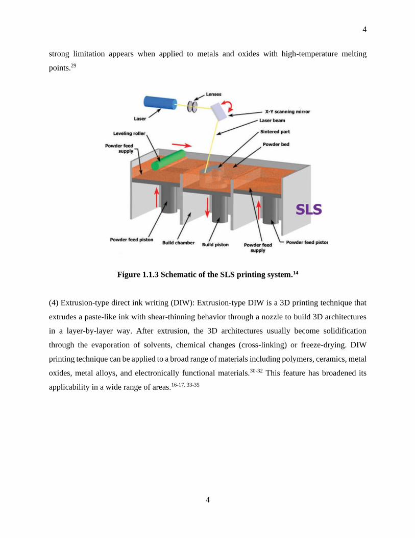
(3) Selective laser sintering (SLS): SLS is a powder-based 3D printing technique that is capable
of constructing durable and functional 3D objects through selectively fusing successive layers of
solid material by a high-power laser beam.26 The un-sintered materials in a printing process can
be reused for another printing job, resulting in a reduction of materials wastage.27-28 However, the
4
4
strong limitation appears when applied to metals and oxides with high-temperature melting
points.29
Figure 1.1.3 Schematic of the SLS printing system.14
(4) Extrusion-type direct ink writing (DIW): Extrusion-type DIW is a 3D printing technique that
extrudes a paste-like ink with shear-thinning behavior through a nozzle to build 3D architectures
in a layer-by-layer way. After extrusion, the 3D architectures usually become solidification
through the evaporation of solvents, chemical changes (cross-linking) or freeze-drying. DIW
printing technique can be applied to a broad range of materials including polymers, ceramics, metal
oxides, metal alloys, and electronically functional materials.30-32 This feature has broadened its
applicability in a wide range of areas.16-17, 33-35

5
5
Figure 1.1.4 Schematic of the extrusion-type DIW printing system.36
Compared with conventional manufacturing methods, the 3D printing technique possesses several
advantages for fabricating EES devices:
(1) The thickness of electrodes can be well controlled by 3D printing because of the layer-by-layer
additive manufacturing nature. Thin-film devices can be fabricated by just depositing materials
over a few layers, which could be applicable for flexible and wearable energy storage devices. On
the other hand, ultra-thick electrodes can also be obtained by 3D printing, realizing high areal
energy density EES devices. Therefore, the accurate layer-by-layer building feature of 3D printing
allows the electrode thickness to be well controlled.
(2) 3D printing can realize facile and accurate construction of electrodes and other components
with controlled shapes, and interconnected porosity.19, 37-39 The designed 3D architectures with
periodic or aligned pores enable fast ion/electron transport which is beneficial for achieving high
power density and energy density.
(3) 3D printing technique can fabricate micro-structured EES devices with high-aspect-ratio within
a small areal footprint, which is hardly realized by conventional manufacturing methods.40

6
6
Meanwhile, the printed EES devices can be easily on-chip integrated with other shape complexed
electronics through directly depositing the electrodes/electrolytes onto the electronics.41-42
(4) 3D printing is a low-cost, efficient, and environment-friendly technology. This can be
attributed to the simplified one-step fabrication process. 3D printing adopts the additive
manufacturing strategy, suggesting that the material is deposited on demand. This feature
maximally eliminates the materials wastage, making it much more energy-conservation and
environment-friendly than conventional manufacturing methods.
Among lots of developed printing techniques, extrusion-type direct ink writing is the most popular
and widely used in many areas. In recent years, numerous researches have employed this technique
to design novel structures for energy storage devices.
1.2 3D printing of electrodes for energy storage
1.2.1 3D-printed electrodes for Li-ion batteries
Li-ion batteries have been commercialized for decades and been widely used in various areas
including portable electronics and electric vehicles.43-47 As one of the most important components
in the LIBs system, electrodes play a vital role in determining the capacity and energy density. To
meet the increasing energy density demand, many efforts have been devoted to optimizing the
electrode structures for improving the electron/ion kinetics. In recent years, many researchers have
employed 3D printing technique to fabricate advanced LIB electrodes with high performance. For
instance, Pan et al. reported the 3D printing of LiMn1-xFexPO4 nanocrystal cathodes and assembled
the LIBs based on the printed electrodes.48 Figure 1.2.1a is the schematic illustration of 3D
printing of LMFP cathode and the packaging process based on the printed LMFP electrode. The
synthesis process for the LMFP nanocrystals involves precursor calcination and carbon coating.
The LMFP slurry was extruded out through a metal nozzle and directly printed onto an Al foil.
The electrode morphology can be adjusted by changing the dispenser pressure, printing speed, and
the diameter of the nozzle. The electrochemical performance testing in Figure 1.2.1b and c shows
that the 3D-printed LMFP cathodes exhibited much higher capacity at various rates than that of
the traditional electrodes. More recently, 3D printing technique was used to fabricate high-
performance Li-ion battery anodes. Rahul et at. developed a novel approach for fabricating 3D
microlattice Ag electrodes with hierarchical porosity through Aerosol Jet (AJ) 3D printing method
(Figure 1.2.1d).49 The microlattice Ag electrode delivered a great improvement in areal capacity
7
7
and high electrode volume utilization when compared to a solid Ag bulk electrode. The superior
electrochemical performances indicate that the 3D microlattice architectures can effectively
facilitate the electrolyte penetration into the electrode and enhance the electrochemical reaction
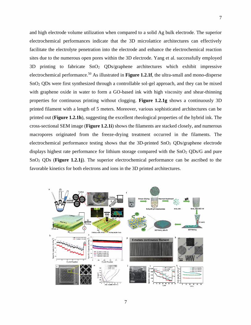
sites due to the numerous open pores within the 3D electrode. Yang et al. successfully employed
3D printing to fabricate SnO2 QDs/graphene architectures which exhibit impressive
electrochemical performance.50 As illustrated in Figure 1.2.1f, the ultra-small and mono-disperse
SnO2 QDs were first synthesized through a controllable sol-gel approach, and they can be mixed
with graphene oxide in water to form a GO-based ink with high viscosity and shear-thinning
properties for continuous printing without clogging. Figure 1.2.1g shows a continuously 3D
printed filament with a length of 5 meters. Moreover, various sophisticated architectures can be
printed out (Figure 1.2.1h), suggesting the excellent rheological properties of the hybrid ink. The
cross-sectional SEM image (Figure 1.2.1i) shows the filaments are stacked closely, and numerous
macropores originated from the freeze-drying treatment occurred in the filaments. The
electrochemical performance testing shows that the 3D-printed SnO2 QDs/graphene electrode
displays highest rate performance for lithium storage compared with the SnO2 QDs/G and pure
SnO2 QDs (Figure 1.2.1j). The superior electrochemical performance can be ascribed to the
favorable kinetics for both electrons and ions in the 3D printed architectures.
8
8
Figure 1.2.1 (a) Schematic illustration of 3D printing of LMFP cathode and battery package
process based on 3D-printed LMFP electrode; (b) Rate capability comparison between the
conventional electrode and 3D-printed LMFP electrode at various rates; (c) Long cycling
performance comparison between the traditional electrode and 3D-printed electrode at 10C
and 20C;48 (d) SEM images of the 3D-printed Ag microlattice structures using the Aerosol
Jet 3D printing method; (e) Areal capacity comparison of the microlattice and block
structures with different thickness;49 (f) Schematic of the 3D printing of SnO2 QDs/G
architectures; (g) Digital image of the continuously 3D-printed filament; (h) Digital images
of various 3D-printed patterns; (i) Cross-sectional SEM image of the printed SnO2 QDs/G
architectures; (j) Rate capabilities comparison among the 3DP-SnO2 QDs/G, SnO2 QDs/G
and SnO2 QDs; (k) Areal capacities of 2-layer, 4-layer, and 6-layer 3DP-SnO2 QDs/G
architectures. 50
1.2.2 3D-printed electrodes for Li-S battery
Lithium-sulfur (Li-S) batteries have emerged as a promising substitute to LIBs due to the high
theoretical capacity of 1675 mAh g-1 and an energy density of 2600 Wh g-1.51-53 However,
developing high loading sulfur-based cathodes with high-performance is still facing great
challenges: (1) Both sulfur and lithium sulfides have a low electron conductivity, making charge
transfer difficult in the cathode; (2) A large volumetric expansion (80%) happens during the
lithiation process, leading to exfoliation of the cathode and rapid capacity decay.54-56
For solving these problems, fabricating of a 3D architecture with interconnected electron and ion
channels within the electrode is quite promising for improving the sulfur utilization for high-
loading sulfur cathodes.57-58 In this regard, the 3D printing technique has been employed to
construct high-loading sulfur cathodes since 3D printing technique has great advantages in
fabricating complex 3D architectures and easily controlling the sulfur loadings by controlling the
printing layers. For instance, Craig et al. reported the Li-S battery cathodes fabricated by the direct
ink writing method based on a printable multiwall carbon nanotubes (MWCNTs) ink.59 The printed
MWCNTs-based sulfur electrodes are highly conductive and multi-scaled porous, which can
facilitate the electrolyte access into the electrodes and enhance the electron/ion diffusion. As a
result, the printed micro-electrodes can achieve a high areal capacity of around 7 mAh cm-2 at a
9
9
current density of 11.5 mA cm-2 with 50% active material loading. More recently, Yang et al.
employed an extrusion-based 3D printing approach to developing 3D sulfur copolymer-graphene
architectures (3DP-pSG) with well-designed periodic microlattices.60 Figure 1.2.2a demonstrates
the fabrication procedure of 3D printing sulfur copolymer-graphene architectures. The printing ink
is based on highly concentrated graphene oxide (GO) suspensions composed of S particles and
1,3-diisopropenylbenzene (DIB). The sulfur copolymer is formed onto the surface of reduced
graphene oxide (RGO) after a sample thermal treatment of the 3D printed architectures. The
resultant structures can partially suppress poly-sulfides dissolution into electrolyte due to the
strong S-C bonds and enhance the electron conductivity because of the formed graphene network.
Moreover, the well-designed macropores in the 3D architectures as shown in Figure 1.2.2b can
promote the access of electrolyte to the electrodes. The 3DP-pSG electrode thus delivers a higher
reversible capacity of 812.8 mAh g-1 with a high thickness of around 600 µm. Although the 3D-
printed sulfur copolymer-graphene architecture could improve the capacity of thick electrodes, the
initial capacity is still too low due to the low electronic conductivity of the sulfur copolymer.
In this regard, our group developed a 3D-printed freeze-dried S/C composite electrode (3DP-FDE)
via a facile 3D printing technique for achieving high-energy-density and high-power-density Li-S
batteries.61 As illustrated in Figure 1.2.2e, the printing ink is composed of the S/C active materials,
acetylene black (AB) and commercial carbon nanotubes (CNTs) as the conductive additives, and
polyvinylidene fluoride-hexafluoro propylene (PVDF-HFP) as the binder. The high loading
amount of sulfur cathodes can be easily obtained via the layer-by-layer manufacturing process.
The printed sulfur cathodes possess multiple levels of porosity: macroscale (several hundred
micrometers from 3D printing design), and microscale (tens of micrometers induced by phase-
inversion and freeze-drying process), which can effectively facilitate the electron/ion transport
within the whole electrodes (Figure 1.2.2f-h). Benefiting from the hierarchical porous
architectures, the 3DP-FDE exhibits superior electrochemical performance, even with a sulfur
loading of 5.5 mg cm-2, it can display high initial discharge capacities of 1009 mAh g-1 and 912
mAh g-1 at 1C and 2C (corresponding to areal current densities of 9.2 mA cm-2 and 18.4 mA cm-
2), respectively. Moreover, the capacity retentions are as high as 87% and 85% after 200 cycles at
1C and 2C (Figure 1.2.2i).

10
10
Figure 1.2.2 (a) Schematic illustration of 3D printing sulfur copolymer-graphene (3DP-pSG)
architectures; (b) Top-view SEM image of the 3D architecture, showing periodic macropores;
(c) Cross-sectional SEM image of the 3D architecture; (d) Cycle performances of 3DP-pSG
and 3DP-SG at 50 mA g-1;60 (e) Schematic demonstration of the 3D printing of S/BP 2000
thick cathodes; (f-h) SEM images of the 3D electrode at different magnifications from top
view; (i) Cycling performance of the 3DP-FDE electrodes with a sulfur loading of 5.5 mg cm-
2 at various rates.61
1.2.3 3D-printed electrodes for Li-O2/CO2 batteries
Li-O2 batteries with Li metal as the anode and O2 cathode possess extremely high theoretical
specific capacity energy (3505 Wh kg-1), which has attracted great attention in the past few years.62-
66 However, the insulating Li2O2 formed during the discharging process greatly restricts the
practical specific energy. By using a porous conducting matrix to support and confine the
accumulated insulating Li2O2 within the pores, the electrode capacity and the practical specific
energy density can be considerably enhanced. Thus, it is vital to develop a conducting catalyst
material with a proper porous framework.
Extrusion-based 3D printing has been proven to be a powerful tool for constructing complex 3D
architecture. Recently, Hu et at. employed extrusion-based 3D printing to construct hierarchical
porous frameworks and demonstrated the first 3D-printed Li-O2 cathodes.67 In their work, the

11
11
printable ink was prepared by directly adding holey graphene oxide (hGO) to H2O at high
concentrations (~100mg/ml). The aqueous hGO ink with proper viscoelastic behavior can be
dispensed fine lines in a layer-by-layer arrangement (Figure 1.2.3a) and be stacked together to
construct complex 3D printed mesh structures (Figure 1.2.3b). The freestanding 3D printed hGO
cathodes possess multi-scaled porosity (from macroscale to nanoscale) as displayed in Figure
1.2.3c and d, which facilitate the mass/ionic transport and improve active-site utilization, leading
to a dramatical enhancement in overall Li-O2 battery performance. The reduced 3D printed h-GO
mesh shows a remarkable areal capacity of 13.3 mAh cm-2 (corresponding to 3879 mAh g-1) when
tested at 0.1 mA cm-2 (Figure 1.2.3 e), which is much higher than that of the vacuum filtrated hGO
film. The result confirms that the macro- and microscale porosity induced by 3D printing play a
critical role in improving the overall air cathode capacity.
Later on, Wang et al. reported a novel and freestanding hierarchically porous framework
constructed by 3D printing of Co-based metal-organic framework (Co-MOF), followed by thermal
annealing. The 3D printed Co-MOF (Figure 1.2.3f and g) exhibits a mesh-like architecture with
macro-sized pores (~200 µm). The 3D printed mesh-like architecture can be well maintained after
annealing in N2 gas (Figure 1.2.3h and i), resulting in the conducting catalyst consisted of Co
nanoparticles assembled in nitrogen-doped mesoporous carbon flakes (3DP-NC-Co). The 3DP-
NC-Co cathode could deliver a high discharge capacity of 1124 mAh g-1 based on the total mass
of the electrode (Figure 1.2.3j). Moreover, the 3DP-NC-Co cathode also exhibits a superior rate
capability, reaching a high discharge capacity of 525 mAh g-1 at a high current density of 0.8 mA
cm-2 (Figure 1.2.3k). The superb Li-O2 battery performance can be attributed to the unique 3DP
architectures consisting of abundant micrometer-sized pores formed between Co-MOF derived
carbon flakes and meso- and micropores formed with the flakes, which benefit the efficient
deposition of Li2O2 and facilitate their decomposition due to the confinement of insulating Li2O2
within the pores and presence of Co electrocatalysts.
12
12
Figure 1.2.3 (a) Digital image showing the process of printing complex 3D architectures line-
by-line; (b) Digital image of the printed hGO mesh after freeze-drying; (c) Optical image of
the printed freeze-dried hGO mesh. Scale bar is 500 µm. (d) Cross-sectional SEM image of
the porous 3D printed hGO mesh structure. Scale bar is 50 µm. (e) Deep discharge
performance of the printed r-hGO mesh;67 (f) and (h) Optical images, (g) and (i) SEM image
of 3DP-Co-MOF and 3DP-NC-Co, respectively; (j) First discharge curves of the marked
cathodes; (k) Rate capability of 3DP-NC-Co with different current densities;68 (i) Schematic
of the synthesis of Ni-rGO framework; (m) Digital images of the GO and Ni-rGO
frameworks; (n) and (o) SEM images of the Ni-rGO; (p) Cycling performance (q)
Discharge/charge curves of the Ni-rGO at various current densities with a limit capacity. 69
1.2.4 3D-printed electrodes for Na-ion batteries
Sodium-ion batteries (SIBs) are attracting tremendous interest recently due to the abundance and
low cost of Na.70-75 However, it is more difficult to achieve high reversible capacities and good
rate capabilities due to the bigger size of Na+ (0.102 nm) than that of Li+ (0.076 nm). 3D printing
has shown great potential in designing unique 3D architectures for optimizing Li-based electrodes
for achieving high-performance LIBs. Similar to LIBs, extrusion-based 3D printing technique has
also been employed in sodium storage.

13
13
For example, Yang et al. first demonstrated a facile 3D printing approach to fabricate hierarchically
porous GO/Na3V2(PO4)3 (GO/NVP) frameworks for sodium storage.76 Figure 1.2.4a illustrates
the process of 3D printing GO/NVP mesh structures, the printable ink was prepared by adding the
NVP nanoparticles into the GO solution. The concentrated GO/NVP inks with suitable rheological
properties can be dispensed into 3D mesh structures. The as-printed frameworks possess
continuous conducting filaments with numerous hierarchical pores (Figure 1.2.4b and c), which
are able to facilitate the fast transportation of both sodium ion and electron. The 3D printed porous
frameworks thus show high capacity and excellent rate performance (Figure 1.2.4d and e).
Following this work, Brown et al. employed a 3D freeze-printing (3DFP) method to fabricate
highly porous MoS2/graphene hybrid aerogels as the anode for SIBs.77 The key innovation in this
work is that a cold substrate plate (-30) is employed to rapidly freeze the aqueous ink droplets
to the ice during the printing (Figure 1.2.4f to j). After thermal reduction, the printed hybrid
aerogels form a continuous conductive rGO framework with MoS2 sheets attached to the graphene
surface as the Na+ intercalation host (Figure 1.2.4k and l). The 3D printed rGO/MoS2 porous
framework thus delivers high specific capacity at various current densities (Figure 1.2.4m).

14
14
Figure 1.2.4 Printed SIBs electrodes via 3D and inkjet printing. (a) Schematic illustration of
3D-printing GO-NVP hierarchical porous frameworks; (b, c) SEM images of 3D-printed
GO-NVP architectures at different magnifications; (d) Cycle performance at 2C, and (e) rate
capability of the 3D-printed rGO-NVP electrodes;76 Schematic of (f) the inkjet printing setup,
and (g, h) the printing process of the ATM-GO droplets in a raster fashion, ice template
formation (i) during printing, and the resulting ATM-GO aerogel after freeze-drying (j); (k)
An example macrostructure of the 3D printed ATM-GO aerogel after freeze-drying and the
resulting MoS2-rGO aerogel after thermal reduction; (l) High-magnification SEM image of
the MoS2-rGO printed on a Ni foam; (m) Rate performance of the MoS2-rGO aerogel at
various current densities.77

15
15
1.2.5 3D-printed electrodes for supercapacitors
Supercapacitors are a promising class of energy storage devices that could balance the high energy
density and high-power density.78-82 However, there are still lots of challenges for achieving high-
performance supercapacitors due to the sluggish of electron/ion transport within thick electrodes.
Recently, 3D printing technology has provided some new possibilities to address the existing
challenges in supercapacitors.83-84
3D-printed GO aerogels based-electrodes have shown great potential in high-performance
supercapacitors. For example, Li et al. reported the fabrication of 3D graphene composite aerogel
microlattices via a DIW 3D printing technique for supercapacitor.85 As illustrated in Figure 1.2.5a,
the printable inks consist of GO, graphene nanoplate (GNP), and silica fillers. The 3D-printed
graphene composite aerogel (3D-GCA) electrodes with engineered periodic macroporosity can
facilitate mass transport, resulting in excellent electrochemical properties. Gao et al. developed a
facile ion-induced gelation method to fabricate graphene aerogels microlattices (GAMs) from GO-
based ink.86 By adding trace of Ca2+, the aqueous GO can be converted into printable ink with
suitable rheological properties (Figure 1.2.5e). The well-designed hierarchical pores and excellent
compressibility and electrical conductivity of the GAMs ensure admirable supercapacitor
performances. The 3D-printed GAMs thus display extraordinary capacitive rate and cycle
performance. Following their previous work, Li et at. recently reported a 3D printed graphene
aerogel scaffold, followed by electrodepositing MnO2 on the printed scaffold.87 The 3D printed
aerogels are macroporous with 5-50 µm pores within the 3D printed filaments as shown in Figure
1.2.5. The 3D architectures facilitate uniform deposition of MnO2 throughout the entire graphene
aerogel and efficient ion diffusion during charging/discharging even at an ultrahigh mass loading
of 182.2 mg cm-2, achieving a record-high areal capacitance of 44.13 F cm-2. More importantly,
the liner increasing of areal capacitance with the thickness of 3D printed monolithic electrodes
suggests great potential for practical application and could innovate the conventional layer-by-
layer stacking fabrication process of commercial supercapacitors.

16
16
Figure 1.2.5 (a) Schematic illustration of 3D printing graphene aerogel microlattice. (b)
Gravimetric capacitance and capacitive retention calculated as a function of current density.
Inset: schematic demonstration of the 3S-GCA SSC. (c) Cycling performance measured at a
scan rate of 200 mV/s for 10 000 cycles. Inset shows the first and last cyclic voltammograms
collected during the cycling stability test. (d) Comparison of the 3D-GCA SSC with reported
values in terms of gravimetric energy densities and power densities.85 (e) Schematic of 3D
printing rGO microlattice based on GO-CaCl2 ink. (f) Optical image of the printed GO
microlattice. (g) SEM image of the printed GO microlattice. (h-j) Electrochemical
performance of the 3D printed rGO microlattice.86 (k) Schematic of fabrication of a 3D
printed graphene aerogel/MnO2 electrode. (l) SEM image of the 3D printed graphene
aerogel/MnO2 electrode. (m) Gravimetric capacitances and volumetric capacitances of the
3D G/MnO2 electrodes with different mass loading of MnO2. (n) Areal capacitances of 3D
G/MnO2 and non-3D printed G/MnO2 electrodes at different current densities. 87

17
17
1.3 3D printing of electrolytes and separator membranes for energy storage
Electrolytes / separator membranes are one of the important components in a battery system.
However, the conventional liquid electrolytes have serious limitations in 3D cell assembly and
safety problems, which limits the form factors, design of flexible batteries, and realization of high-
energy-density Li-metal batteries. In this case, it is vital to develop advanced electrolytes to replace
the liquid electrolytes. Moreover, advanced preparation methods are required to design flexible
and even 3D structured electrolyte and separator membranes for meeting alien shaped batteries.
Extrusion-based 3D printing technique has shown great potential in fabricating flexible separator
membranes and 3D structured solid electrolytes.
1.3.1 3D printing of polymer separator for Li-metal batteries
Li-metal anodes have received great attention for advanced Li-metal based batteries in recent years,
such as Li-O2 and Li-S batteries, because of its high theoretical capacity (3860 mAh g-1) and low
redox potential (-3.04 V vs standard hydrogen electrode).88-97 However, several intrinsic problems,
like the growth of Li dendrites, infinite volume change, and high chemical reactivity, have greatly
hindered its widespread utilization in consumer markets.98-99 Many efforts have been devoted to
solving these challenges. Designing a functional separator membrane can be a facile and effective
approach to suppress the Li dendrite growth for improving the cycling performance of Li metal
batteries100-104.
Recently, 3D printing technique has been used to fabricate functional separators for Li metal
batteries as 3D printing is a facile and sophisticated strategy for multi-materials design and
fabrication. Hu et al. first reported the fabrication of a novel and safe boron nitride (BN)/PVDF-
HFP composite separator via an extrusion-based 3D printing method105. The printed BN-based
separator owes good flexibility with good mechanical strength (Figure 1.3.1b). The exiting of BN
nanosheets in the separator could ensure a uniform thermal distribution at the interface, resulting
in homogeneous Li nucleation. The symmetric cells with printed BN/PVDF-HFP separator thus
displayed enhanced cycling stability with a lower overpotential over 500h (Figure 1.3.1f-i).

18
18
Figure 1.3.1 (a) Schematic illustration of the 3D printing machine and BN in PVDF-HFP
separator; (b) Optical images of the 3D-printed BN/PVDF-HFP separator at different stages
during the printing process;105 (c-e) SEM images of the 3D-BN/PVDF-HFP separator; (f-i)
Cycling performance of the Li-Li symmetric cells at a current density of 1 mA cm-2
1.3.2 3D printing of Solid-State Electrolyte
For achieving high-energy-density Li-metal batteries, solid-state electrolyte should be applied to
replace the traditional unsafe liquid electrolytes. However, the conventional solid-state electrolyte
with a flat and planar geometry usually shows a high interfacial impedance due to the limited
contact area between the electrolyte and electrodes.106-110 Furthermore, the conventional
manufacturing method is hard to obtain a thin solid electrolyte (less than 150 µm), leading to a
decreased energy density due to the high weight of the solid electrolytes.111-112
Accordingly, 3D printing, as advanced manufacturing technology, can be employed to design
solid-state electrolytes with unique microstructures to solve the aforementioned challenges. Hu et
al. for the first time developed multiple solid electrolyte inks using garnet-type Li7La3Zr2O12
(LLZO) as a model material and successfully fabricated various micro-structured LLZO solid
electrolyte via an advanced extrusion 3D printing approach113. Figure 1.3.2a illustrated the cell
fabrication process using the 3D printed LLZO solid electrolyte. Micro-structured and porous
LLZO based on the “self-supporting” ink was printed on both sides of an LLZO tape substrate and
sintered revealing thin and 3D architectures composed only of LLZO solid electrolyte. Electrodes
can be infiltrated into the printed microporous LLZO to complete battery assembly. A symmetric
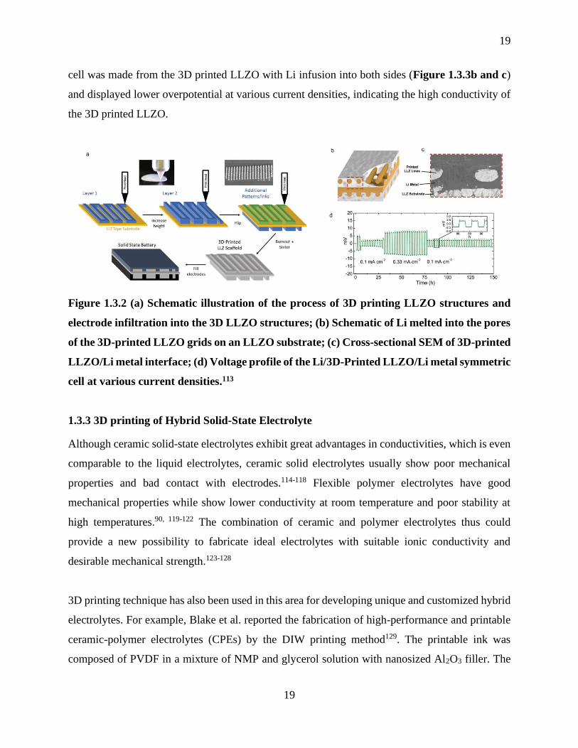
19
19
cell was made from the 3D printed LLZO with Li infusion into both sides (Figure 1.3.3b and c)
and displayed lower overpotential at various current densities, indicating the high conductivity of
the 3D printed LLZO.
Figure 1.3.2 (a) Schematic illustration of the process of 3D printing LLZO structures and
electrode infiltration into the 3D LLZO structures; (b) Schematic of Li melted into the pores
of the 3D-printed LLZO grids on an LLZO substrate; (c) Cross-sectional SEM of 3D-printed
LLZO/Li metal interface; (d) Voltage profile of the Li/3D-Printed LLZO/Li metal symmetric
cell at various current densities.113
1.3.3 3D printing of Hybrid Solid-State Electrolyte
Although ceramic solid-state electrolytes exhibit great advantages in conductivities, which is even
comparable to the liquid electrolytes, ceramic solid electrolytes usually show poor mechanical
properties and bad contact with electrodes.114-118 Flexible polymer electrolytes have good
mechanical properties while show lower conductivity at room temperature and poor stability at
high temperatures.90, 119-122 The combination of ceramic and polymer electrolytes thus could
provide a new possibility to fabricate ideal electrolytes with suitable ionic conductivity and
desirable mechanical strength.123-128
3D printing technique has also been used in this area for developing unique and customized hybrid
electrolytes. For example, Blake et al. reported the fabrication of high-performance and printable
ceramic-polymer electrolytes (CPEs) by the DIW printing method129. The printable ink was
composed of PVDF in a mixture of NMP and glycerol solution with nanosized Al2O3 filler. The
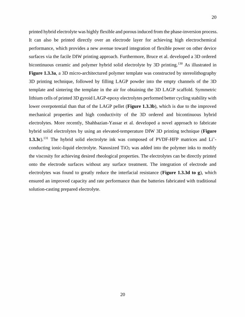
20
20
printed hybrid electrolyte was highly flexible and porous induced from the phase-inversion process.
It can also be printed directly over an electrode layer for achieving high electrochemical
performance, which provides a new avenue toward integration of flexible power on other device
surfaces via the facile DIW printing approach. Furthermore, Bruce et al. developed a 3D ordered
bicontinuous ceramic and polymer hybrid solid electrolyte by 3D printing.130 As illustrated in
Figure 1.3.3a, a 3D micro-architectured polymer template was constructed by stereolithography
3D printing technique, followed by filling LAGP powder into the empty channels of the 3D
template and sintering the template in the air for obtaining the 3D LAGP scaffold. Symmetric
lithium cells of printed 3D gyroid LAGP-epoxy electrolytes performed better cycling stability with
lower overpotential than that of the LAGP pellet (Figure 1.3.3b), which is due to the improved
mechanical properties and high conductivity of the 3D ordered and bicontinuous hybrid
electrolytes. More recently, Shahbazian-Yassar et al. developed a novel approach to fabricate
hybrid solid electrolytes by using an elevated-temperature DIW 3D printing technique (Figure
1.3.3c).131 The hybrid solid electrolyte ink was composed of PVDF-HFP matrices and Li+-
conducting ionic-liquid electrolyte. Nanosized TiO2 was added into the polymer inks to modify
the viscosity for achieving desired rheological properties. The electrolytes can be directly printed
onto the electrode surfaces without any surface treatment. The integration of electrode and
electrolytes was found to greatly reduce the interfacial resistance (Figure 1.3.3d to g), which
ensured an improved capacity and rate performance than the batteries fabricated with traditional
solution-casting prepared electrolyte.

21
21
Figure 1.3.3 (a) Schematic of the fabrication process of 3D-printed hybrid electrolytes.
Corresponding SEM images of each synthesis stage of the 3D LAGP-epoxy hybrid
electrolytes are listed below each schematic; (b) Galvanostatic cycling of Li-Li cells with
LAGP pellet and gyroid LAGP-epoxy electrolytes cycled at a current density of 0.7 mA cm-
2;130 (c) Schematic of the elevated-temperature direct ink writing system and solid-electrolyte
ink fabrication process; (d-g) Electrochemical impedance spectroscopy (EIS) of the hybrid
solid-state electrolyte.131
1.4 All 3D-Printed Energy Storage Devices
1.4.1 All 3D-printed LIBs/LMBs
With the development of microscale technologies, future electronic devices are becoming smaller
and miniaturized. In this case, a micro lithium-ion battery would be in great need to power these
miniaturized devices, such as microscale sensors,132-133 microscale actuators,134-136, and portable
and implantable medical devices.137-138 Although 2D thin-film micro-batteries have been greatly
developed and could deliver a high-power density, it is a big challenge for thin-film micro-batteries
to achieve a high energy density due to the low active materials loading.139-140 3D micro-batteries
could be a promising strategy for powering the miniaturizing electronic devices.141-142 Traditional

22
22
methods including electrodeposition and vapor deposition technique have been demonstrated to
fabricate 3D electrodes with high-aspect-ration micropillar structures.143-145 However, these
methods are inefficient and expensive, which are not suitable for large-scale applications. In
contrast, 3D printing has been proven to be a promising technique to construct various 3D
architectures.
In 2013, the Lewis group first fabricated an interdigitated 3D micro-battery composed of 3D
printed high-aspect-ratio LTO anode and LFO cathode micro-arrays that are directly printed on a
gold current collector (Figure 1.4.1a and b).146 The printed fully packaged 3D micro-battery
(Figure 1.4.1c) exhibited a high areal energy density of 9.7 J cm-2 at a power density of 2.7 mW
cm-2. Later on, Hu and coworkers successfully fabricated an interdigitated Li-ion micro-battery
via a 3D printing technique based on graphene oxide (GO) composite inks consisting of highly
concentrated GO suspensions with the cathode (LFP) and anode (LTO) active materials added
(Figure 1.4.1d and e).147 The printed full cell displayed a relatively stable discharge capacity of
91 mA h g-1 (Figure 1.4.1 f and g), corresponding to a high areal capacity of 1.64 mA h cm-2 based
on the high electrode mass loading of around 18 mg cm-2. Very recently, 3D printing technique
has been employed to fabricate high-performance Li metal batteries (LMBs) with a 3D-printed Li
anode and a 3D-printed LFP cathode by using cellulose nanofiber (CNF)-based inks (Figure
1.4.1k),148 which significantly improved the energy density due to the utilization of the printed Li
metal anode. The main novelty of this work is the utilization of printed c-CNF structures to host
the Li metal forming a 3D c-CNF/Li anode (Figure 1.4.1i-n), which could greatly improve the
cyclic stability of Li metal anode (Figure 1.4.1o).

23
23
Figure 1.4.1 3D-printed interdigitated Li micro-batteries. (a) Schematic illustration of 3D-
printed interdigitated micro-battery architectures on the gold current collector with printed
Li4Ti5O12 (LTO) and LiFePO4 (LFP) as the anode and cathode, followed by packaging. (b)
SEM images of printed and annealed 16-layer interdigitated LTO-LFP electrode
architectures, respectively. (c) Optical image of 3D-printed micro-battery composed of LTO-
LFP electrodes after packaging.146 (d) Schematic of the 3D-printed interdigitated electrodes
with LTO/GO and LFP/GO as the ink for anode and cathode electrodes, respectively. The
gel polymer composite ink is injected in the channel between the annealed electrodes. (e)
Digital image of the interdigitated electrodes. (f) Cycling stability of the 3D-printed full cell.
(g) Charge/discharge profiles of the 3D-printed full cell. (h, i) Digital images of a
miniaturized version of the 3D-printed electrodes. (j) Digital image of the 3D-printed
electrodes arrays.149 (k) Schematic illustration of the CNF ink derived from trees and 3D-
printed LMBs fabricated by printing c-CNF/LFP cathode and c-CNF/Li anode. (i-n)
Photographs of a CNF scaffold after freeze-drying and before carbonization, c-CNF scaffold
after carbonization, and c-CNF/Li electrode with designed 3D structure. (o) Cycling
performance comparison of c-CNF/Li and Li foil in a symmetric cell at a current density of
5 mA cm-2 with areal capacity fixed at 2.5 mAh cm-2.148

24
24
1.4.2 All 3D-Printed Supercapacitors
Micro-supercapacitors (MSCs) have been considered as one of the most promising power sources
for various portable electronics since they can exhibit fast charge/discharge, relatively high
capacity, and excellent cycling stability.150-156 However, most of the reported micro-
supercapacitors show lower areal energy densities, which limited their further development in
many areas.157-159
3D printing has been explored to fabricate various 3D micro-structured supercapacitor electrodes
and even 3D Li-ion micro-batteries with high areal capacity. Based on previous studies, Yang et
al. first reported the fabrication of quasi-solid-state asymmetric micro-supercapacitors (MSC) via
an extrusion-based 3D printing approach for realizing high areal energy density (74 µWh cm-2).160
The fabrication process included the printing of interdigitated electrodes and gel-like electrolyte
on the substrate (Figure 1.4.2a). A thick electrode (412 µm) with an areal mass loading of 3 mg
cm-2 was fabricated with the printing method (Figure 1.4.2b). The 3D printed micro-
supercapacitor thus delivered an ultrahigh areal capacitance of 208 mF cm-2, which outperforms
most of the reported interdigitated micro-supercapacitors (Figure 1.4.2c and d).
Apart from designing 3D micro-supercapacitors, 3D printing has also been employed to fabricate
fiber-shaped asymmetric supercapacitors (FASCs). Although fiber-shaped supercapacitors have
been widely studied, most of the fabrication methods used in the reported studies have limitations
in fabrication cost, efficiency, and scalability that hinder their wide application in wearable
devices.161-172 In this case, as illustrated in Figure 1.4.2e, a facile and low-cost extrusion-based 3D
printing approach was developed to fabricate an all-fiber integrated electronic device via
combining printed fiber-shaped temperature sensors (FTSs) with printed FASCs.173 It should be
noted that the PVA/KOH gel electrolyte was also printed on the as-printed positive and negative
fibers (Figure 1.4.2 g). The assembled all printed fiber device showed high flexibility and
excellent cycling stability under repeated bending (Figure 1.4.2h-k).

25
25
Figure 1.4.2 (a) Schematic illustration of 3D printing of an interdigitated asymmetric MSC
on the gold current collector. The gel-like electrolyte was injected into the channels between
the anode and cathode. (b) SEM image of 3D-printed 4-layer electrodes. (c) Areal and
volumetric capacitances of the 3D printed asymmetric MSC. (d) Comparison of the 3D
printed MSC and other reported asymmetric interdigitated MSCs.160 (e) Schematic of 3D
printing of the FASC device. (f) Digital image of the wet fiber during the printing process.
(g, h) SEM images of the printed fiber electrode and assembled FASC device. (i) Schematic
of the assembled FASCs device. (j) CV of the assembled device measured at different voltage
window. (k) Capacitance retention of the FASC devices after repeated bending.173
1.4.3 All 3D-printed Zn-based Batteries
In addition to Li/Na batteries, Zn-based battery is another new type energy storage system, which
has attracted much attention due to the low cost of zinc metal and high safety of using aqueous
electrolytes.174-184 Printing techniques are efficient and low-cost additive manufacturing method.
Thus, the employment of printing technique in Zn-based batteries can further reduce the total
fabrication cost and improve the efficiency, thereby boosting the development of Zn-based
batteries as promising energy storage system, especially wearable power source systems.185-187
For example, Wang et al. first reported the fabrication of a rechargeable, skin-worn Ag-Zn tattoo
battery consisting of screen-printed electrodes, temporary tattoo paper, alkaline gel electrolytes
and a PDMS cover for sealing the battery (Figure 1.4.3a).188 The designed Ag-Zn tattoo battery
exhibited a high capacity in the range of 1.3-2.1 mAh cm-2 and can be easily worn by a person for

26
26
powering a red LED. Steingart et al. reported highly flexible, printed Zn-MnO2 batteries based on
mesh-embedded electrodes by using the stencil printing method.189 As illustrated in Figure 1.4.3b,
a nylon mesh was applied as a support for the electroactive inks. The Zn and MnO2 inks were then
stencil printed on the nylon-mesh substrates. Silver ink was stencil printed onto the mesh as the
current collector. Finally, the battery was assembled by stacking the mesh-embedded electrodes
and a PAA gel polymer electrolyte. The flexible Zn-MnO2 battery displayed a high discharge
capacity of 5.6 mAh cm-2 at a current of 0.5 mA. Moreover, the discharge capacity remained well
without any decrease even after repeated bending. Wang et al. reported for the first time an all-
printed, stretchable Zn-Ag2O rechargeable battery by using low-cost screen printing of highly
elastic, conductive inks.190 The novelty of this study hinged on the using of polystyrene-block-
polyisoprene-block-polystyrene (SIS) as an elastic binder for stretchable batteries. The printed Zn-
Ag2O battery can be stretched into various shapes and exhibited a reversible capacity of around
2.5 mAh cm-2 even after multiple iterations of 100% stretching. Despite the great progress in
printed Zn-based batteries, the capacity densities are still not desirable. More recently,
Subramanian et al. developed a packaged, fully printed Zn-Ag2O battery with a vertical cell
geometry by using the stencil printing approach (Figure1.4.3d).191 The printed battery was
constructed by a zinc anode and a monovalent silver oxide cathode with an aqueous potassium
hydroxide (KOH) electrolyte. The fully printed cell with vertical geometry and electrodes as small
as 1 mm2 was achieved, demonstrating a high areal capacity of 11 mAh cm-2 with 250 µm thick
electrodes.
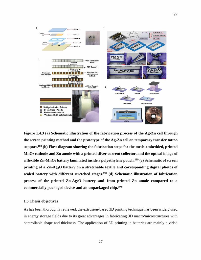
27
27
Figure 1.4.3 (a) Schematic illustration of the fabrication process of the Ag-Zn cell through
the screen printing method and the prototype of the Ag-Zn cell on temporary transfer tattoo
support.188 (b) Flow diagram showing the fabrication steps for the mesh-embedded, printed
MnO2 cathode and Zn anode with a printed silver current collector, and the optical image of
a flexible Zn-MnO2 battery laminated inside a polyethylene pouch.189 (c) Schematic of screen
printing of a Zn-Ag2O battery on a stretchable textile and corresponding digital photos of
sealed battery with different stretched stages.190 (d) Schematic illustration of fabrication
process of the printed Zn-Ag2O battery and 1mm printed Zn anode compared to a
commercially packaged device and an unpackaged chip.191
1.5 Thesis objectives
As has been thoroughly reviewed, the extrusion-based 3D printing technique has been widely used
in energy storage fields due to its great advantages in fabricating 3D macro/microstructures with
controllable shape and thickness. The application of 3D printing in batteries are mainly divided

28
28
into three categories: 1) 3D printing of advanced anodes or cathodes, 2) 3D printing of solid-state
electrolytes, and 3) fabrication of all 3D-printed high-energy-density micro-structured batteries.
Based on this, the thesis objectives are divided into five topics.
(1) To fabricate 3D macro/micro-structured Li-ion battery cathodes (LiFePO4) via the 3D printing
method. The designed 3D structures can facilitate the electron/ion transport within thick electrodes,
which can realize high energy and power density LIBs.
(2) To construct hierarchically porous Si electrodes via a low-cost and efficient 3D printing
approach. The 3D-printed hierarchically porous structures can effectively address the huge volume
change of Si anodes. Meanwhile, the unique structures can allow fast electron/ion transport.
(3) To fabricate thin solid-state electrolytes via a low-cost and scalable 3D printing approach.
Solid-state batteries are promising due to high safety and high energy density. However, it is of
great challenge to fabricate a thin solid electrolyte via a low-cost and facile approach. Thus, 3D
printing offers a promising strategy to fabricate shape-versatile and thin solid electrolytes, which
can reduce the total weight of a cell and shorten the Li+ transport path, thereby increasing the
energy density and power density of a solid battery.
(4) To construct high-performance sodium metal batteries via the 3D printing method. 3D-printed
Na@rGO/CNT composites were fabricated for suppressing the Na dendrite problem during
cycling. Meanwhile, a sodium layered cathode was printed for achieving a high energy density
sodium metal battery.
(5) To develop high-voltage layered oxides cathodes for SIBs. In order to further improve the
energy density of 3D-printed sodium batteries, P2- Na2/3Ni1/3Mn2/3O2 high-voltage cathodes were
synthesized. Atomic layer deposition (ALD) of AlPO4 was applied to the cathode for improving
the cycling performance.
1.6 Thesis outline
The outline of this thesis is listed as follows:
Chapter 1 presents a general introduction of various 3D printing techniques, particularly the
extrusion-type 3D printing technology, and an overview of current research states of extrusion-
type 3D printing applied in fabricating various 3D architectures for energy storages devices.
29
29
Chapter 2 describes the experimental methods and characterization apparatus used in the work of
this thesis.
Chapter 3 describes the employing of extrusion-type 3D printing method for constructing 3D-
patterned ultrathick LiFePO4 electrodes for high-areal-energy and high-power-density LIBs. The
excellent electrochemical performances are attributed to the unique 3D architectures which could
greatly improve the ion and electron transport within the whole electrode.
Chapter 4 demonstrates the realization of patterned silicon electrodes with vertically aligned and
multi-scaled porous structures for achieving high-areal capacity LIBs through a facile and low-
cost 3D printing approach. Compared to conventional flat 2D Si electrodes, the 3D-printed Si
electrodes possess vertically aligned mass/ionic transport pathways and macro/micro-scaled
porosities, which can facilitate the electron/ion transport and effectively mitigate the huge volume
expansion during the cycling process by providing extra free space.
Chapter 5 presents the fabrication of shape-versatile and thin LAGP solid electrolytes for high-
performance solid-state Li-metal batteries via a low-cost and efficient extrusion-based 3D printing
approach. Compared with the conventional pressed thick solid-state electrolyte pellets, the 3D-
printed LAGP thin electrolytes can increase the energy density and power density of a cell. In
addition, various patterned LAGP architectures are easily fabricated, which broadens the diversity
of solid batteries with various size and shapes.
Chapter 6 describes the constructing of a high-performance SMB consisting of a printed
Na@rGO/CNT anode and a printed O3-NaCu1/9Ni2/9Fe3/9Mn3/9O2 (denoted as NCNFM) cathode.
The 3D-printed Na@rGO/CNT can effectively suppress the Na dendrite growth by decreasing the
local current density and releasing the huge volume change of Na during cycling. On the other
hand, the 3D-printed micro-structured NNCFM cathode composed of interconnected CNTs and
porous polymer framework can enable fast electron and ion transport as well as facilitated
electrolyte penetration within the whole electrode.

30
30
Chapter 7 describes the study of using an electrochemically stable nanoscale surface coating of
AlPO4 to stabilize the P2- Na2/3Ni1/3Mn2/3O2 with controllable thickness via atomic layer
deposition (ALD). The right amount of AlPO4 coating layer can suppress the reduction of Mn upon
cycling, thus improving the structural stability of the cathode material.
Chapter 8 presents a summary of the work in this thesis and describes future work.
1.7 References
1. Tarascon, J. M.; Armand, M., Issues and challenges facing rechargeable lithium batteries.
Nature 2001, 414, 359.
2. Chu, S.; Majumdar, A., Opportunities and challenges for a sustainable energy future.
Nature 2012, 488 (7411), 294-303.
3. Winter, M.; Brodd, R. J., What Are Batteries, Fuel Cells, and Supercapacitors? Chem. Rev.
2004, 104 (10), 4245-4270.
4. Chen, K.; Xue, D., Materials chemistry toward electrochemical energy storage. J. Mater.
Chem. A 2016, 4 (20), 7522-7537.
5. Stoller, M. D.; Ruoff, R. S., Best practice methods for determining an electrode material's
performance for ultracapacitors. Energy Environ. Sci. 2010, 3 (9), 1294-1301.
6. Aricò, A. S.; Bruce, P.; Scrosati, B.; Tarascon, J.-M.; van Schalkwijk, W., Nanostructured
materials for advanced energy conversion and storage devices. Nat. Mater. 2005, 4 (5), 366-377.
7. Aurbach, D., Review of selected electrode–solution interactions which determine the performance
of Li and Li ion batteries. J. Power Sources 2000, 89, 206-218.

31
31
8. Salanne, M.; Rotenberg, B.; Naoi, K.; Kaneko, K.; Taberna, P. L.; Grey, C. P.; Dunn, B.;
Simon, P., Efficient storage mechanisms for building better supercapacitors. Nat. Energy 2016, 1,
16070.
9. Abhinav M. Gaikwad; Ana Claudia Arias; Steingart, D. A., Recent Progress on Printed
Flexible Batteries: Mechanical Challenges, Printing Technologies, and Future Prospects. Energy
Tech. 2014, 3, 305-328.
10. Choi, K.-H.; Yoo, J.; Lee, C. K.; Lee, S.-Y., All-inkjet-printed, solid-state flexible
supercapacitors on paper. Energy Environ. Sci. 2016, 9 (9), 2812-2821.
11. Yang, P.; Mai, W., Flexible solid-state electrochemical supercapacitors. Nano Energy 2014,
8, 274-290.
12. Calvert, P., Inkjet Printing for Materials and Devices. Chem. Mater. 2001, 13 (10), 3299-
3305.
13. Symes, M. D.; Kitson, P. J.; Yan, J.; Richmond, C. J.; Cooper, G. J. T.; Bowman, R. W.;
Vilbrandt, T.; Cronin, L., Integrated 3D-printed reactionware for chemical synthesis and analysis.
Nat. Chem. 2012, 4, 349.
14. Ruiz-Morales, J. C.; Tarancón, A.; Canales-Vázquez, J.; Méndez-Ramos, J.; Hernández-
Afonso, L.; Acosta-Mora, P.; Marín Rueda, J. R.; Fernández-González, R., Three dimensional
printing of components and functional devices for energy and environmental applications. Energy
Environ. Sci. 2017.
15. Ambrosi, A.; Pumera, M., 3D-printing technologies for electrochemical applications.
Chem. Soc. Rew. 2016, 45 (10), 2740-2755.

32
32
16. Tang, X.; Zhu, C.; Cheng, D.; Zhou, H.; Liu, X.; Xie, P.; Zhao, Q.; Zhang, D.; Fan, T.,
Architectured Leaf-Inspired Ni0.33Co0.66S2/Graphene Aerogels via 3D Printing for High-
Performance Energy Storage. Adv. Funct. Mater. 2018, 28 (51), 1805057.
17. Díaz-Marta, A. S.; Tubío, C. R.; Carbajales, C.; Fernández, C.; Escalante, L.; Sotelo, E.;
Guitián, F.; Barrio, V. L.; Gil, A.; Coelho, A., Three-Dimensional Printing in Catalysis:
Combining 3D Heterogeneous Copper and Palladium Catalysts for Multicatalytic Multicomponent
Reactions. ACS Catal. 2017, 8 (1), 392-404.
18. Gao, T.; Zhou, Z.; Yu, J.; Zhao, J.; Wang, G.; Cao, D.; Ding, B.; Li, Y., 3D Printing of
Tunable Energy Storage Devices with Both High Areal and Volumetric Energy Densities. Adv.
Energy Mater. 2019, 9 (8), 1802578.
19. Chen, L.; Tang, X.; Xie, P.; Xu, J.; Chen, Z.; Cai, Z.; He, P.; Zhou, H.; Zhang, D.; Fan, T.,
3D Printing of Artificial Leaf With Tunable Hierarchical Porosity for CO2 Photoreduction. Chem.
Mater. 2018, 30, 799-806.
20. Manzano, J. S.; Weinstein, Z. B.; Sadow, A. D.; Slowing, I. I., Direct 3D Printing of
Catalytically Active Structures. ACS Catalysis 2017, 7567-7577.
21. Dudek, P., FDM 3D Printing Technology in Manufacturing Composite Elements. Arch.
Metall. Mater. 2013, 58 (4), 1415-1418.
22. Weng, Z.; Wang, J.; Senthil, T.; Wu, L., Mechanical and thermal properties of
ABS/montmorillonite nanocomposites for fused deposition modeling 3D printing. Mater. Design
2016, 102, 276-283.
23. Nguyen, D. T.; Meyers, C.; Yee, T. D.; Dudukovic, N. A.; Destino, J. F.; Zhu, C.; Duoss,
E. B.; Baumann, T. F.; Suratwala, T.; Smay, J. E.; Dylla-Spears, R., 3D-Printed Transparent Glass.
Adv. Mater. 2017, 29 (26), 1701181-n/a.
33
33
24. Zarek, M.; Layani, M.; Cooperstein, I.; Sachyani, E.; Cohn, D.; Magdassi, S., 3D Printing
of Shape Memory Polymers for Flexible Electronic Devices. Adv. Mater. 2016, 28 (22), 4449-
4454.
25. Layani, M.; Wang, X.; Magdassi, S., Novel Materials for 3D Printing by
Photopolymerization. Adv. Mater. 2018, 30 (41), e1706344.
26. Shirazi, S. F.; Gharehkhani, S.; Mehrali, M.; Yarmand, H.; Metselaar, H. S.; Adib Kadri,
N.; Osman, N. A., A review on powder-based additive manufacturing for tissue engineering:
selective laser sintering and inkjet 3D printing. Sci. Tech. Adv. Mater. 2015, 16 (3), 033502.
27. Mazhar, H.; Osswald, T.; Negrut, D., On the use of computational multi-body dynamics
analysis in SLS-based 3D printing. Addit. Manuf. 2016, 12, 291-295.
28. Tan, W. S.; Chua, C. K.; Chong, T. H.; Fane, A. G.; Jia, A., 3D printing by selective laser
sintering of polypropylene feed channel spacers for spiral wound membrane modules for the water
industry. Virtual and Physical Prototyping 2016, 11 (3), 151-158.
29. J‐P. Kruth, P. M., J. Van Vaerenbergh, L. Froyen, M. Rombouts, Binding Mechanisms in
Selective Laser Sintering and Selective Laser Melting. Rapid Prototyping Journal 2005, 11, 26-
36.
30. Yan, P.; Brown, E.; Su, Q.; Li, J.; Wang, J.; Xu, C.; Zhou, C.; Lin, D., 3D Printing
Hierarchical Silver Nanowire Aerogel with Highly Compressive Resilience and Tensile
Elongation through Tunable Poisson's Ratio. Small 2017, 1701756-n/a.
31. Gao, F.; Xu, Z.; Liang, Q.; Liu, B.; Li, H.; Wu, Y.; Zhang, Y.; Lin, Z.; Wu, M.; Ruan, C.;
Liu, W., Direct 3D Printing of High Strength Biohybrid Gradient Hydrogel Scaffolds for Efficient
Repair of Osteochondral Defect. Adv. Funct. Mater. 2018, 1706644-n/a.
34
34
32. Elsayed, H.; Colombo, P.; Bernardo, E., Direct ink writing of wollastonite-diopside glass-
ceramic scaffolds from a silicone resin and engineered fillers. Journal of the European Ceramic
Society 2017, 37 (13), 4187-4195.
33. Qian, F.; Zhu, C.; Knipe, J. M.; Ruelas, S.; Stolaroff, J. K.; DeOtte, J. R.; Duoss, E. B.;
Spadaccini, C. M.; Henard, C. A.; Guarnieri, M. T.; Baker, S. E., Direct Writing of Tunable Living
Inks for Bioprocess Intensification. Nano Lett. 2019.
34. Zhu, C.; Liu, T.; Qian, F.; Chen, W.; Chandrasekaran, S.; Yao, B.; Song, Y.; Duoss, E. B.;
Kuntz, J. D.; Spadaccini, C. M.; Worsley, M. A.; Li, Y., 3D printed functional nanomaterials for
electrochemical energy storage. Nano Today 2017, 15 (Supplement C), 107-120.
35. Wang, X.; Li, T.; Ma, H.; Zhai, D.; Jiang, C.; Chang, J.; Wang, J.; Wu, C., A 3D-printed
scaffold with MoS2 nanosheets for tumor therapy and tissue regeneration. Npg Asia Mater. 2017,
9, e376.
36. Tian, X.; Jin, J.; Yuan, S.; Chua, C. K.; Tor, S. B.; Zhou, K., Emerging 3D-Printed
Electrochemical Energy Storage Devices: A Critical Review. Adv. Energy Mater. 2017, 7 (17),
1700127.
37. Fu, K.; Yao, Y.; Dai, J.; Hu, L., Progress in 3D Printing of Carbon Materials for Energy-
Related Applications. Adv. Mater. 2017, 29 (9).
38. Zhang, Q.; Zhang, F.; Xu, X.; Zhou, C.; Lin, D., Three-Dimensional Printing Hollow
Polymer Template-Mediated Graphene Lattices with Tailorable Architectures and Multifunctional
Properties. ACS Nano 2018.
39. Choi, K.-H.; Ahn, D. B.; Lee, S.-Y., Current Status and Challenges in Printed Batteries:
Toward Form Factor-Free, Monolithic Integrated Power Sources. ACS Energy Lett. 2017, 3, 220-
236.
35
35
40. Liu, L.; Weng, Q.; Lu, X.; Sun, X.; Zhang, L.; Schmidt, O. G., Advances on Microsized
On-Chip Lithium-Ion Batteries. Small 2017, 13 (45).
41. Kim, F.; Kwon, B.; Eom, Y.; Lee, J. E.; Park, S.; Jo, S.; Park, S. H.; Kim, B.-S.; Im, H. J.;
Lee, M. H.; Min, T. S.; Kim, K. T.; Chae, H. G.; King, W. P.; Son, J. S., 3D printing of shape-
conformable thermoelectric materials using all-inorganic Bi2Te3-based inks. Nat. Energy 2018.
42. Kim, S.-H.; Choi, K.-H.; Cho, S.-J.; Yoo, J.; Lee, S.-S.; Lee, S.-Y., Flexible/Shape-
Versatile, Bipolar All-Solid-State Lithium-Ion Batteries Prepared by Multistage Printing. Energy
Environ. Sci. 2017.
43. Etacheri, V.; Marom, R.; Elazari, R.; Salitra, G.; Aurbach, D., Challenges in the
development of advanced Li-ion batteries: a review. Energy Environ. Sci. 2011, 4 (9), 3243.
44. Lu, L.; Han, X.; Li, J.; Hua, J.; Ouyang, M., A review on the key issues for lithium-ion
battery management in electric vehicles. J. Power Sources 2013, 226, 272-288.
45. Nitta, N.; Wu, F.; Lee, J. T.; Yushin, G., Li-ion battery materials: present and future. Mater.
Today 2015, 18 (5), 252-264.
46. Feng, X.; Ouyang, M.; Liu, X.; Lu, L.; Xia, Y.; He, X., Thermal runaway mechanism of
lithium ion battery for electric vehicles: A review. Energy Storage Mater. 2018, 10, 246-267.
47. Blomgren, G. E., The Development and Future of Lithium Ion Batteries. J. Electrochem.
Soc. 2016, 164 (1), A5019-A5025.
48. Hu, J.; Jiang, Y.; Cui, S.; Duan, Y.; Liu, T.; Guo, H.; Lin, L.; Lin, Y.; Zheng, J.; Amine,
K.; Pan, F., 3D-Printed Cathodes of LiMn1−xFexPO4 Nanocrystals Achieve Both Ultrahigh Rate
and High Capacity for Advanced Lithium-Ion Battery. Adv. Energy Mater. 2016, 6, 1600856.

36
36
49. Saleh, M. S.; Li, J.; Park, J.; Panat, R., 3D printed hierarchically-porous microlattice
electrode materials for exceptionally high specific capacity and areal capacity lithium ion batteries.
Addit. Manuf. 2018, 23, 70-78.
50. Zhang, C.; Shen, K.; Li, B.; Li, S.; Yang, S., Continuously 3D printed quantum dot-based
electrodes for lithium storage with ultrahigh capacities. J. Mater. Chem. A 2018, 6 (41), 19960-
19966.
51. Nazar, S. E. a. L. F., New Approaches for High Energy Density Lithium-Sulfur Battery
Cathodes. Acc. Chem. Res. 2013, 46 (5), 1135-1143.
52. Yin, Y. X.; Xin, S.; Guo, Y. G.; Wan, L. J., Lithium-sulfur batteries: electrochemistry,
materials, and prospects. Angew. Chem. Int. Ed. Engl. 2013, 52 (50), 13186-200.
53. Liu, X.; Huang, J. Q.; Zhang, Q.; Mai, L., Nanostructured Metal Oxides and Sulfides for
Lithium-Sulfur Batteries. Adv. Mater. 2017, 29 (20).
54. Peng, H.-J.; Huang, J.-Q.; Cheng, X.-B.; Zhang, Q., Review on High-Loading and High-
Energy Lithium-Sulfur Batteries. Adv. Energy Mater. 2017, 7 (24), 1700260.
55. Peng, H.-J.; Xu, W.-T.; Zhu, L.; Wang, D.-W.; Huang, J.-Q.; Cheng, X.-B.; Yuan, Z.; Wei,
F.; Zhang, Q., 3D Carbonaceous Current Collectors: The Origin of Enhanced Cycling Stability for
High-Sulfur-Loading Lithium-Sulfur Batteries. Adv. Funct. Mater. 2016, 26 (35), 6351-6358.
56. Qie, L.; Zu, C.; Manthiram, A., A High Energy Lithium-Sulfur Battery with Ultrahigh-
Loading Lithium Polysulfide Cathode and its Failure Mechanism. Adv. Energy Mater. 2016, 6 (7),
1502459.
57. Zhang, J.; Li, J.-Y.; Wang, W.-P.; Zhang, X.-H.; Tan, X.-H.; Chu, W.-G.; Guo, Y.-G.,
Microemulsion Assisted Assembly of 3D Porous S/Graphene@g-C3N4 Hybrid Sponge as Free-
37
37
Standing Cathodes for High Energy Density Li-S Batteries. Adv. Energy Mater. 2018, 8 (14),
1702839.
58. Zhang, J.; Huang, H.; Bae, J.; Chung, S.-H.; Zhang, W.; Manthiram, A.; Yu, G.,
Nanostructured Host Materials for Trapping Sulfur in Rechargeable Li-S Batteries: Structure
Design and Interfacial Chemistry. Small Methods 2018, 2 (1), 1700279.
59. Milroy, C.; Manthiram, A., Printed Microelectrodes for Scalable, High-Areal-Capacity
Lithium–Sulfur Batteries. Chem. Commun. 2016, 52 (23), 4282-4285.
60. Shen, K.; Mei, H.; Li, B.; Ding, J.; Yang, S., 3D Printing Sulfur Copolymer-Graphene
Architectures for Li-S Batteries. Adv. Energy Mater. 2018, 8 (4), 1701527.
61. Gao, X.; Sun, Q.; Yang, X.; Liang, J.; Koo, A.; Li, W.; Liang, J.; Wang, J.; Li, R.; Holness,
F. B.; Price, A. D.; Yang, S.; Sham, T.-K.; Sun, X., Toward a Remarkable Li-S battery via 3D
Printing. Nano Energy 2019, 56, 595-603.
62. Peng, Z.; Freunberger, S. A.; Chen, Y.; Bruce, P. G., A reversible and higher-rate Li-O2
battery. Science 2012, 337 (6094), 563-566.
63. Lau, S.; Archer, L. A., Nucleation and Growth of Lithium Peroxide in the Li-O2 Battery.
Nano Lett. 2015, 15 (9), 5995-6002.
64. Feng, N.; He, P.; Zhou, H., Critical Challenges in Rechargeable Aprotic Li-O2Batteries.
Adv. Energy Mater. 2016, 6 (9), 1502303.
65. Chang, Z.; Xu, J.; Zhang, X., Recent Progress in Electrocatalyst for Li-O2
Batteries. Adv. Energy Mater. 2017, 7 (23), 1700875.
38
38
66. Kwak, W.-J.; Kim, H.; Jung, H.-G.; Aurbach, D.; Sun, Y.-K., Review—A Comparative
Evaluation of Redox Mediators for Li-O2Batteries: A Critical Review. J. Electrochem. Soc. 2018,
165 (10), A2274-A2293.
67. Lacey, S. D.; Kirsch, D. J.; Li, Y.; Morgenstern, J. T.; Zarket, B. C.; Yao, Y.; Dai, J.; Garcia,
L. Q.; Liu, B.; Gao, T.; Xu, S.; Raghavan, S. R.; Connell, J. W.; Lin, Y.; Hu, L., Extrusion-Based
3D Printing of Hierarchically Porous Advanced Battery Electrodes. Adv. Mater. 2016, 1705651-
n/a.
68. Lyu, Z.; Lim, G. J. H.; Guo, R.; Kou, Z.; Wang, T.; Guan, C.; Ding, J.; Chen, W.; Wang,
J., 3D-Printed MOF-Derived Hierarchically Porous Frameworks for Practical High-Energy
Density Li–O2 Batteries. Adv. Funct. Mater. 2019, 29 (1), 1806658.
69. Qiao, Y.; Liu, Y.; Chen, C.; Xie, H.; Yao, Y.; He, S.; Ping, W.; Liu, B.; Hu, L., 3D-Printed
Graphene Oxide Framework with Thermal Shock Synthesized Nanoparticles for Li-CO2 Batteries.
Adv. Funct. Mater. 2018, 28 (51), 1805899.
70. Pan, H.; Hu, Y.-S.; Chen, L., Room-temperature stationary sodium-ion batteries for large-
scale electric energy storage. Energy Environ. Sci. 2013, 6 (8), 2338-2360.
71. Han, M. H.; Gonzalo, E.; Singh, G.; Rojo, T., A comprehensive review of sodium layered
oxides: powerful cathodes for Na-ion batteries. Energy Environ. Sci. 2015, 8 (1), 81-102.
72. Kim, H.; Kim, H.; Ding, Z.; Lee, M. H.; Lim, K.; Yoon, G.; Kang, K., Recent Progress in
Electrode Materials for Sodium-Ion Batteries. Adv. Energy Mater. 2016, 6 (19), 1600943-n/a.
73. Hwang, J.-Y.; Myung, S.-T.; Sun, Y.-K., Sodium-ion batteries: present and future. Chem.
Soc. Rew. 2017, 46 (12), 3529-3614.

39
39
74. Ni, Q.; Bai, Y.; Wu, F.; Wu, C., Polyanion-Type Electrode Materials for Sodium-Ion
Batteries. Adv. Sci. 2017, 4 (3), 1600275-n/a.
75. Ortiz Vitoriano, N.; Drewett, N.; Gonzalo, E.; Rojo, T., High Performance Manganese-
based Layered Oxide Cathodes: Overcoming the Challenges of Sodium Ion Batteries. Energy
Environ. Sci. 2017.
76. Ding, J.; Shen, K.; Du, Z.; Li, B.; Yang, S., 3D-Printed Hierarchical Porous Frameworks
for Sodium Storage. ACS Appl. Mater. Interfaces 2017, 9 (48), 41871-41877.
77. Brown, E.; Yan, P.; Tekik, H.; Elangovan, A.; Wang, J.; Lin, D.; Li, J., 3D printing of
hybrid MoS2-graphene aerogels as highly porous electrode materials for sodium ion battery anodes.
Mater. Design 2019, 170, 107689.
78. Gogotsi, P. S. a. Y., Materials for electrochemical capacitors. Nat. Mater. 2008, 7, 845-
854.
79. Augustyn, V.; Simon, P.; Dunn, B., Pseudocapacitive oxide materials for high-rate
electrochemical energy storage. Energy Environ. Sci. 2014, 7 (5), 1597-1614.
80. Augustyn, V.; Come, J.; Lowe, M. A.; Kim, J. W.; Taberna, P.-L.; Tolbert, S. H.; Abruña,
H. D.; Simon, P.; Dunn, B., High-rate electrochemical energy storage through Li+ intercalation
pseudocapacitance. Nat. Mater. 2013, 12, 518.
81. Lukatskaya, M. R.; Mashtalir, O.; Ren, C. E.; Dall’Agnese, Y.; Rozier, P.; Taberna, P. L.;
Naguib, M.; Simon, P.; Barsoum, M. W.; Gogotsi, Y., Cation Intercalation and High Volumetric
Capacitance of Two-Dimensional Titanium Carbide. Science 2013, 341 (6153), 1502-1505.
82. Ghidiu, M.; Lukatskaya, M. R.; Zhao, M.-Q.; Gogotsi, Y.; Barsoum, M. W., Conductive
two-dimensional titanium carbide ‘clay’ with high volumetric capacitance. Nature 2014, 516, 78.
40
40
83. Wang, Z.; Zhang, Q. E.; Long, S.; Luo, Y.; Yu, P.; Tan, Z.; Bai, J.; Qu, B.; Yang, Y.; Shi,
J.; Zhou, H.; Xiao, Z. Y.; Hong, W.; Bai, H., Three-Dimensional Printing of Polyaniline/Reduced
Graphene Oxide Composite for High-Performance Planar Supercapacitor. ACS Appl. Mater.
Interfaces 2018, 10 (12), 10437-10444.
84. Zhang, F.; Wei, M.; Viswanathan, V. V.; Swart, B.; Shao, Y.; Wu, G.; Zhou, C., 3D
printing technologies for electrochemical energy storage. Nano Energy 2017, 40, 418-431.
85. Zhu, C.; Liu, T.; Qian, F.; Han, T. Y.; Duoss, E. B.; Kuntz, J. D.; Spadaccini, C. M.;
Worsley, M. A.; Li, Y., Supercapacitors Based on Three-Dimensional Hierarchical Graphene
Aerogels with Periodic Macropores. Nano Lett. 2016, 16 (6), 3448-56.
86. Jiang, Y.; Xu, Z.; Huang, T.; Liu, Y.; Guo, F.; Xi, J.; Gao, W.; Gao, C., Direct 3D Printing
of Ultralight Graphene Oxide Aerogel Microlattices. Adv. Funct. Mater. 2018, 28 (16), 1707024.
87. Yao, B.; Chandrasekaran, S.; Zhang, J.; Xiao, W.; Qian, F.; Zhu, C.; Duoss, E. B.;
Spadaccini, C. M.; Worsley, M. A.; Li, Y., Efficient 3D Printed Pseudocapacitive Electrodes with
Ultrahigh MnO2 Loading. Joule 2019, 3 (2), 459-470.
88. Lin, D.; Liu, Y.; Cui, Y., Reviving the lithium metal anode for high-energy batteries. Nat.
Nanotech. 2017, 12 (3), 194-206.
89. Zhang, R.; Chen, X.-R.; Chen, X.; Cheng, X.-B.; Zhang, X.-Q.; Yan, C.; Zhang, Q.,
Lithiophilic Sites in Doped Graphene Guide Uniform Lithium Nucleation for Dendrite-Free
Lithium Metal Anodes. Angew. Chem. Int. Ed. Engl. 2017, 56 (27), 7764-7768.
90. Zhang, X.; Wang, S.; Xue, C.; Xin, C.; Lin, Y.; Shen, Y.; Li, L.; Nan, C.-W., Self-
Suppression of Lithium Dendrite in All-Solid-State Lithium Metal Batteries with Poly(vinylidene
difluoride)-Based Solid Electrolytes. Adv. Mater. 2019, 31 (11), 1806082.

41
41
91. Lu, Z.; Liang, Q.; Wang, B.; Tao, Y.; Zhao, Y.; Lv, W.; Liu, D.; Zhang, C.; Weng, Z.;
Liang, J.; Li, H.; Yang, Q.-H., Graphitic Carbon Nitride Induced Micro-Electric Field for Dendrite-
Free Lithium Metal Anodes. Adv. Energy Mater. 2019, 9 (7), 1803186.
92. Zeng, X.-X.; Yin, Y.-X.; Shi, Y.; Zhang, X.-D.; Yao, H.-R.; Wen, R.; Wu, X.-W.; Guo,
Y.-G., Lithiation-Derived Repellent toward Lithium Anode Safeguard in Quasi-solid Batteries.
Chem 2018.
93. Xu, Y.; Menon, A. S.; Harks, P. P. R. M. L.; Hermes, D. C.; Haverkate, L. A.; Unnikrishnan,
S.; Mulder, F. M., Honeycomb-like porous 3D nickel electrodeposition for stable Li and Na metal
anodes. Energy Storage Mater. 2018, 12, 69-78.
94. Xu, R.; Zhang, X.-Q.; Cheng, X.-B.; Peng, H.-J.; Zhao, C.-Z.; Yan, C.; Huang, J.-Q.,
Artificial Soft–Rigid Protective Layer for Dendrite-Free Lithium Metal Anode. Adv. Funct. Mater.
2018, 1705838-n/a.
95. Guo, F.; Wang, Y.; Kang, T.; Liu, C.; Shen, Y.; Lu, W.; Wu, X.; Chen, L., A Li-dual carbon
composite as stable anode material for Li batteries. Energy Storage Mater. 2018, 15, 116-123.
96. Zhu, B.; Jin, Y.; Hu, X.; Zheng, Q.; Zhang, S.; Wang, Q.; Zhu, J., Poly(dimethylsiloxane)
Thin Film as a Stable Interfacial Layer for High-Performance Lithium-Metal Battery Anodes. Adv.
Mater. 2017, 29 (2), 1603755-n/a.
97. Raji, A.-R. O.; Villegas Salvatierra, R.; Kim, N. D.; Fan, X.; Li, Y.; Silva, G. A. L.; Sha,
J.; Tour, J. M., Lithium Batteries with Nearly Maximum Metal Storage. ACS Nano 2017.
98. Ye, H.; Xin, S.; Yin, Y.-X.; Guo, Y.-G., Advanced Porous Carbon Materials for High-
Efficient Lithium Metal Anodes. Adv. Energy Mater. 2017, 1700530-n/a.
42
42
99. Liu, Y.; Liu, Q.; Xin, L.; Liu, Y.; Yang, F.; Stach, E. A.; Xie, J., Making Li-metal
electrodes rechargeable by controlling the dendrite growth direction. Nat. Energy 2017, 2, 17083.
100. Luo, W.; Zhou, L.; Fu, K.; Yang, Z.; Wan, J.; Manno, M.; Yao, Y.; Zhu, H.; Yang, B.; Hu,
L., A Thermally Conductive Separator for Stable Li Metal Anodes. Nano Lett. 2015, 15 (9), 6149-
6154.
101. Pan, R.; Xu, X.; Sun, R.; Wang, Z.; Lindh, J.; Edström, K.; Strømme, M.; Nyholm, L.,
Nanocellulose Modified Polyethylene Separators for Lithium Metal Batteries. Small 2018, 14 (21),
1704371.
102. Liu, Y.; Xiong, S.; Wang, J.; Jiao, X.; Li, S.; Zhang, C.; Song, Z.; Song, J., Dendrite-free
lithium metal anode enabled by separator engineering via uniform loading of lithiophilic
nucleation sites. Energy Storage Mater. 2019, 19, 24-30.
103. Li, Y.; Wang, W.; Liu, X.; Mao, E.; Wang, M.; Li, G.; Fu, L.; Li, Z.; Eng, A. Y. S.; Seh,
Z. W.; Sun, Y., Engineering stable electrode-separator interfaces with ultrathin conductive
polymer layer for high-energy-density Li-S batteries. Energy Storage Mater. 2019.
104. Li, C.; Liu, S.; Shi, C.; Liang, G.; Lu, Z.; Fu, R.; Wu, D., Two-dimensional molecular
brush-functionalized porous bilayer composite separators toward ultrastable high-current density
lithium metal anodes. Nat. Commun. 2019, 10 (1), 1363.
105. Liu, Y.; Qiao, Y.; Zhang, Y.; Yang, Z.; Gao, T.; Kirsch, D.; Liu, B.; Song, J.; Yang, B.;
Hu, L., 3D printed separator for the thermal management of high-performance Li metal anodes.
Energy Storage Mater. 2018, 12, 197-203.
106. Kotobuki, M.; Munakata, H.; Kanamura, K.; Sato, Y.; Yoshida, T., Compatibility of
Li7La3Zr2O12 Solid Electrolyte to All-Solid-State Battery Using Li Metal Anode. J. Electrochem.
Soc. 2010, 157 (10), A1076.

43
43
107. Fu, K.; Gong, Y.; Dai, J.; Gong, A.; Han, X.; Yao, Y.; Wang, C.; Wang, Y.; Chen, Y.; Yan,
C.; Li, Y.; Wachsman, E. D.; Hu, L., Flexible, solid-state, ion-conducting membrane with 3D
garnet nanofiber networks for lithium batteries. Proc. Natl. Acad. Sci. 2016, 113 (26), 7094-7099.
108. Li, P.; Dong, X.; Li, C.; Liu, J.; Liu, Y.; Feng, W.; Wang, C.; Wang, Y.; Xia, Y., Anchoring
an Artificial Solid–Electrolyte Interphase Layer on a 3D Current Collector for High-Performance
Lithium Anodes. Angew. Chem. Int. Ed. Engl. 2019, 58 (7), 2093-2097.
109. Gong, Y.; Fu, K.; Xu, S.; Dai, J.; Hamann, T. R.; Zhang, L.; Hitz, G. T.; Fu, Z.; Ma, Z.;
McOwen, D. W.; Han, X.; Hu, L.; Wachsman, E. D., Lithium-ion conductive ceramic textile: A
new architecture for flexible solid-state lithium metal batteries. Mater. Today 2018.
110. Jiang, Z.; Xie, H.; Wang, S.; Song, X.; Yao, X.; Wang, H., Perovskite Membranes with
Vertically Aligned Microchannels for All-Solid-State Lithium Batteries. Adv. Energy Mater. 2018,
8 (27), 1801433.
111. Wu, B.; Wang, S.; Evans Iv, W. J.; Deng, D. Z.; Yang, J.; Xiao, J., Interfacial behaviours
between lithium ion conductors and electrode materials in various battery systems. J. Mater. Chem.
A 2016, 4 (40), 15266-15280.
112. Betz, J.; Bieker, G.; Meister, P.; Placke, T.; Winter, M.; Schmuch, R., Theoretical versus
Practical Energy: A Plea for More Transparency in the Energy Calculation of Different
Rechargeable Battery Systems. Adv. Energy Mater. 2018, 1803170.
113. McOwen, D. W.; Xu, S.; Gong, Y.; Wen, Y.; Godbey, G. L.; Gritton, J. E.; Hamann, T. R.;
Dai, J.; Hitz, G. T.; Hu, L.; Wachsman, E. D., 3D-Printing Electrolytes for Solid-State Batteries.
Adv. Mater. 2018, 30 (18), e1707132.
114. Inda, Y.; Katoh, T.; Baba, M., Development of all-solid lithium-ion battery using Li-ion
conducting glass-ceramics. J. Power Sources 2007, 174 (2), 741-744.

44
44
115. Asl, N. M.; Keith, J.; Lim, C.; Zhu, L.; Kim, Y., Inorganic solid/organic liquid hybrid
electrolyte for use in Li-ion battery. Electrochimica Acta 2012, 79, 8-16.
116. Liu, Y.; Li, C.; Li, B.; Song, H.; Cheng, Z.; Chen, M.; He, P.; Zhou, H., Germanium Thin
Film Protected Lithium Aluminum Germanium Phosphate for Solid-State Li Batteries. Adv.
Energy Mater. 2018, 8 (16), 1702374.
117. Bae, J.; Li, Y.; Zhao, F.; Zhou, X.; Ding, Y.; Yu, G., Designing 3D nanostructured garnet
frameworks for enhancing ionic conductivity and flexibility in composite polymer electrolytes for
lithium batteries. Energy Storage Mater. 2018, 15, 46-52.
118. Fu, K.; Gong, Y.; Hitz, G. T.; McOwen, D. W.; Li, Y.; Xu, S.; Wen, Y.; Zhang, L.; Wang,
C.; Pastel, G.; Dai, J.; Liu, B.; Xie, H.; Yao, Y.; Wachsman, E. D.; Hu, L., Three-dimensional
bilayer garnet solid electrolyte based high energy density lithium metal–sulfur batteries. Energy
Environ. Sci. 2017, 10 (7), 1568-1575.
119. Pitawala, H. M. J. C.; Dissanayake, M. A. K. L.; Seneviratne, V. A., Combined effect of
Al2O3 nano-fillers and EC plasticizer on ionic conductivity enhancement in the solid polymer
electrolyte (PEO)9LiTf. Solid State Ionics 2007, 178 (13), 885-888.
120. Syzdek, J.; Armand, M.; Marcinek, M.; Zalewska, A.; Żukowska, G.; Wieczorek, W.,
Detailed studies on the fillers modification and their influence on composite, poly(oxyethylene)-
based polymeric electrolytes. Electrochimica Acta 2010, 55 (4), 1314-1322.
121. Sheng, O.; Jin, C.; Luo, J.; Yuan, H.; Huang, H.; Gan, Y.; Zhang, J.; Xia, Y.; Liang, C.;
Zhang, W.; Tao, X., Mg2B2O5 Nanowire Enabled Multifunctional Solid-State Electrolytes with
High Ionic Conductivity, Excellent Mechanical Properties, and Flame-Retardant Performance.
Nano Lett. 2018, 18 (5), 3104-3112.

45
45
122. Zhai, H.; Xu, P.; Ning, M.; Cheng, Q.; Mandal, J.; Yang, Y., A Flexible Solid Composite
Electrolyte with Vertically Aligned and Connected Ion-Conducting Nanoparticles for Lithium
Batteries. Nano Lett. 2017, 17 (5), 3182-3187.
123. Zheng, J.; Tang, M.; Hu, Y.-Y., Lithium Ion Pathway within Li7La3Zr2O12-Polyethylene
Oxide Composite Electrolytes. Angew. Chem. Int. Ed. Engl. 2016, 55 (40), 12538-12542.
124. Xie, H.; Yang, C.; Fu, K.; Yao, Y.; Jiang, F.; Hitz, E.; Liu, B.; Wang, S.; Hu, L., Flexible,
Scalable, and Highly Conductive Garnet-Polymer Solid Electrolyte Templated by Bacterial
Cellulose. Adv. Energy Mater. 2018, 8 (18), 1703474.
125. Fan, L.; Wei, S.; Li, S.; Li, Q.; Lu, Y., Recent Progress of the Solid-State Electrolytes for
High-Energy Metal-Based Batteries. Adv. Energy Mater. 2018, 8 (11), 1702657.
126. Zhang, W.; Nie, J.; Li, F.; Wang, Z. L.; Sun, C., A durable and safe solid-state lithium
battery with a hybrid electrolyte membrane. Nano Energy 2018, 45, 413-419.
127. Dirican, M.; Yan, C.; Zhu, P.; Zhang, X., Composite solid electrolytes for all-solid-state
lithium batteries. Materials Science and Engineering: R: Reports 2019, 136, 27-46.
128. Zhang, X.; Xie, J.; Shi, F.; Lin, D.; Liu, Y.; Liu, W.; Pei, A.; Gong, Y.; Wang, H.; Liu, K.;
Xiang, Y.; Cui, Y., Vertically Aligned and Continuous Nanoscale Ceramic–Polymer Interfaces in
Composite Solid Polymer Electrolytes for Enhanced Ionic Conductivity. Nano Lett. 2018, 18 (6),
3829-3838.
129. Blake, A. J.; Kohlmeyer, R. R.; Hardin, J. O.; Carmona, E. A.; Maruyama, B.; Berrigan, J.
D.; Huang, H.; Durstock, M. F., 3D Printable Ceramic-Polymer Electrolytes for Flexible High-
Performance Li-Ion Batteries with Enhanced Thermal Stability. Adv. Energy Mater. 2017,
1602920.

46
46
130. Zekoll, S.; Marriner-Edwards, C.; Hekselman, A. K. O.; Kasemchainan, J.; Kuss, C.;
Armstrong, D. E. J.; Cai, D.; Wallace, R. J.; Richter, F. H.; Thijssen, J. H. J.; Bruce, P. G., Hybrid
electrolytes with 3D bicontinuous ordered ceramic and polymer microchannels for all-solid-state
batteries. Energy Environ. Sci. 2018, 11 (1), 185-201.
131. Cheng, M.; Jiang, Y.; Yao, W.; Yuan, Y.; Deivanayagam, R.; Foroozan, T.; Huang, Z.;
Song, B.; Rojaee, R.; Shokuhfar, T.; Pan, Y.; Lu, J.; Shahbazian-Yassar, R., Elevated-Temperature
3D Printing of Hybrid Solid-State Electrolyte for Li-Ion Batteries. Adv. Mater. 2018, 30 (39),
1800615.
132. Morrish, W.; West, P.; Orlando, N.; Klantsataya, E.; Gardner, K.; Lane, S.; Decorby, R.;
Francois, A.; Meldrum, A., Refractometric micro-sensor using a mirrored capillary resonator. Opt.
Express 2016, 24 (22), 24959-24970.
133. Q. Fang, D. G. C., J. W. Gardner, Micro-gas-sensor with conducting polymers. Sensors
and Actuators B 2002, 84, 66-71.
134. Hines, L.; Petersen, K.; Lum, G. Z.; Sitti, M., Soft Actuators for Small-Scale Robotics. Adv.
Mater. 2017, 29 (13).
135. Lee, H. T.; Kim, M. S.; Lee, G. Y.; Kim, C. S.; Ahn, S. H., Shape Memory Alloy (SMA)-
Based Microscale Actuators with 60% Deformation Rate and 1.6 kHz Actuation Speed. Small
2018, 14 (23), e1801023.
136. Sinatra, N. R.; Ranzani, T.; Vlassak, J. J.; Parker, K. K.; Wood, R. J., Nanofiber-reinforced
soft fluidic micro-actuators. J. Micromech. Microeng. 2018, 28 (8), 084002.
137. Wise, R. M. H. a. K. D., A 3D implantable microsystem for intraocular pressure monitoring
using a glass-in-silicon reflow process. IEEE 2011, 23-27.
47
47
138. Hodgins, D.; Bertsch, A.; Post, N.; Frischholz, M.; Volckaerts, B.; Spensley, J.;
Wasikiewicz, J. M.; Higgins, H.; von Stetten, F.; Kenney, L., Healthy Aims: Developing New
Medical Implants and Diagnostic Equipment. IEEE Pervas. Comput. 2008, 7 (1), 14-21.
139. Salian, G. D.; Lebouin, C.; Demoulin, A.; Lepihin, M. S.; Maria, S.; Galeyeva, A. K.;
Kurbatov, A. P.; Djenizian, T., Electrodeposition of polymer electrolyte in nanostructured
electrodes for enhanced electrochemical performance of thin-film Li-ion microbatteries. J. Power
Sources 2017, 340, 242-246.
140. Sugiawati, V. A.; Vacandio, F.; Knauth, P.; Djenizian, T., Sputter-Deposited Amorphous
LiCuPO4 Thin Film as Cathode Material for Li-ion Microbatteries. Chem. Select 2018, 3 (2), 405-
409.
141. Ferrari, S.; Loveridge, M.; Beattie, S. D.; Jahn, M.; Dashwood, R. J.; Bhagat, R., Latest
advances in the manufacturing of 3D rechargeable lithium microbatteries. J. Power Sources 2015,
286, 25-46.
142. Ning, H.; Pikul, J. H.; Zhang, R.; Li, X.; Xu, S.; Wang, J.; Rogers, J. A.; King, W. P.;
Braun, P. V., Holographic patterning of high-performance on-chip 3D lithium-ion microbatteries.
Proc. Natl. Acad. Sci. 2015, 112 (21), 6573-6578.
143. Kristina Edstrom, D. B., and Leif Nyholm, Electrodeposition as a Tool for 3D Microbattery
Fabrication. Electrochem. Soc. Interface 2011, 20 (2), 41-46.
144. Li, W.; Bradley, L. C.; Watkins, J. J., Copolymer Solid-State Electrolytes for 3D
Microbatteries via Initiated Chemical Vapor Deposition. ACS Appl. Mater. Interfaces 2019, 11 (6),
5668-5674.
145. Johns, P.; Roberts, M.; Owen, J., Conformal electrodeposition of manganese dioxide onto
reticulated vitreous carbon for 3D microbattery applications. J. Mater. Chem. 2011, 21 (27), 10153.

48
48
146. Sun, K.; Wei, T. S.; Ahn, B. Y.; Seo, J. Y.; Dillon, S. J.; Lewis, J. A., 3D printing of
interdigitated Li-ion microbattery architectures. Adv. Mater. 2013, 25 (33), 4539-43.
147. Fu, K.; Wang, Y.; Yan, C.; Yao, Y.; Chen, Y.; Dai, J.; Lacey, S.; Wang, Y.; Wan, J.; Li,
T.; Wang, Z.; Xu, Y.; Hu, L., Graphene Oxide-Based Electrode Inks for 3D-Printed Lithium-Ion
Batteries. Adv. Mater. 2016, 28, 2587-2594.
148. Cao, D.; Xing, Y.; Tantratian, K.; Wang, X.; Ma, Y.; Mukhopadhyay, A.; Cheng, Z.; Zhang,
Q.; Jiao, Y.; Chen, L.; Zhu, H., 3D Printed High-Performance Lithium Metal Microbatteries
Enabled by Nanocellulose. Adv. Mater. 2019, 31 (14), e1807313.
149. Fu, K.; Wang, Y.; Yan, C.; Yao, Y.; Chen, Y.; Dai, J.; Lacey, S.; Wang, Y.; Wan, J.; Li,
T.; Wang, Z.; Xu, Y.; Hu, L., Graphene Oxide-Based Electrode Inks for 3D-Printed Lithium-Ion
Batteries. Adv. Mater. 2016, 28 (13), 2587-2594.
150. Lethien, C.; Le Bideau, J.; Brousse, T., Challenges and prospects of 3D micro-
supercapacitors for powering the internet of things. Energy Environ. Sci. 2019, 12 (1), 96-115.
151. Gao, W.; Singh, N.; Song, L.; Liu, Z.; Reddy, A. L. M.; Ci, L.; Vajtai, R.; Zhang, Q.; Wei,
B.; Ajayan, P. M., Direct laser writing of micro-supercapacitors on hydrated graphite oxide films.
Nat. Nanotech. 2011, 6, 496.
152. El-Kady, M. F.; Kaner, R. B., Scalable fabrication of high-power graphene micro-
supercapacitors for flexible and on-chip energy storage. Nat. Commun. 2013, 4, 1475.
153. Wu, Z. S.; Parvez, K.; Feng, X.; Mullen, K., Graphene-based in-plane micro-
supercapacitors with high power and energy densities. Nat. Commun. 2013, 4, 2487.
154. Liu, W.-W.; Feng, Y.-Q.; Yan, X.-B.; Chen, J.-T.; Xue, Q.-J., Superior Micro-
Supercapacitors Based on Graphene Quantum Dots. Adv. Funct. Mater. 2013, 23 (33), 4111-4122.
49
49
155. Kyeremateng, N. A.; Brousse, T.; Pech, D., Microsupercapacitors as miniaturized energy-
storage components for on-chip electronics. Nat. Nanotech. 2017, 12 (1), 7-15.
156. Qi, D.; Liu, Y.; Liu, Z.; Zhang, L.; Chen, X., Design of Architectures and Materials in In-
Plane Micro-supercapacitors: Current Status and Future Challenges. Adv. Mater. 2017, 29 (5).
157. Wang, K.; Zou, W.; Quan, B.; Yu, A.; Wu, H.; Jiang, P.; Wei, Z., An All-Solid-State
Flexible Micro-supercapacitor on a Chip. Adv. Energy Mater. 2011, 1 (6), 1068-1072.
158. Kurra, N.; Hota, M. K.; Alshareef, H. N., Conducting polymer micro-supercapacitors for
flexible energy storage and Ac line-filtering. Nano Energy 2015, 13, 500-508.
159. Zhang, C.; Kremer, M. P.; Seral-Ascaso, A.; Park, S.-H.; McEvoy, N.; Anasori, B.; Gogotsi,
Y.; Nicolosi, V., Stamping of Flexible, Coplanar Micro-Supercapacitors Using MXene Inks. Adv.
Funct. Mater. 2018, 28 (9), 1705506.
160. Shen, K.; Ding, J.; Yang, S., 3D Printing Quasi-Solid-State Asymmetric Micro-
Supercapacitors with Ultrahigh Areal Energy Density. Adv. Energy Mater. 2018, 8 (20), 1800408.
161. Yang, Z.; Deng, J.; Chen, X.; Ren, J.; Peng, H., A highly stretchable, fiber-shaped
supercapacitor. Angew. Chem. Int. Ed. Engl. 2013, 52 (50), 13453-7.
162. Chen, X.; Lin, H.; Deng, J.; Zhang, Y.; Sun, X.; Chen, P.; Fang, X.; Zhang, Z.; Guan, G.;
Peng, H., Electrochromic fiber-shaped supercapacitors. Adv. Mater. 2014, 26 (48), 8126-32.
163. Yu, J.; Lu, W.; Smith, J. P.; Booksh, K. S.; Meng, L.; Huang, Y.; Li, Q.; Byun, J.-H.; Oh,
Y.; Yan, Y.; Chou, T.-W., A High Performance Stretchable Asymmetric Fiber-Shaped
Supercapacitor with a Core-Sheath Helical Structure. Adv. Energy Mater. 2017, 7 (3), 1600976.

50
50
164. Xu, P.; Gu, T.; Cao, Z.; Wei, B.; Yu, J.; Li, F.; Byun, J.-H.; Lu, W.; Li, Q.; Chou, T.-W.,
Carbon Nanotube Fiber Based Stretchable Wire-Shaped Supercapacitors. Adv. Energy Mater.
2014, 4 (3), 1300759.
165. Jin, H.; Zhou, L.; Mak, C. L.; Huang, H.; Tang, W. M.; Chan, H. L. W., High-performance
fiber-shaped supercapacitors using carbon fiber thread (CFT)@polyanilne and functionalized CFT
electrodes for wearable/stretchable electronics. Nano Energy 2015, 11, 662-670.
166. Chen, T.; Hao, R.; Peng, H.; Dai, L., High-performance, stretchable, wire-shaped
supercapacitors. Angew. Chem. Int. Ed. Engl. 2015, 54 (2), 618-22.
167. Wang, Q.; Wang, X.; Xu, J.; Ouyang, X.; Hou, X.; Chen, D.; Wang, R.; Shen, G., Flexible
coaxial-type fiber supercapacitor based on NiCo2O4 nanosheets electrodes. Nano Energy 2014, 8,
44-51.
168. Fu, Y.; Cai, X.; Wu, H.; Lv, Z.; Hou, S.; Peng, M.; Yu, X.; Zou, D., Fiber supercapacitors
utilizing pen ink for flexible/wearable energy storage. Adv. Mater. 2012, 24 (42), 5713-5718.
169. Wang, X.; Liu, B.; Liu, R.; Wang, Q.; Hou, X.; Chen, D.; Wang, R.; Shen, G., Fiber-based
flexible all-solid-state asymmetric supercapacitors for integrated photodetecting system. Angew.
Chem. Int. Ed. Engl. 2014, 53 (7), 1849-53.
170. Zhang, Q.; Xu, W.; Sun, J.; Pan, Z.; Zhao, J.; Wang, X.; Zhang, J.; Man, P.; Guo, J.; Zhou,
Z.; He, B.; Zhang, Z.; Li, Q.; Zhang, Y.; Xu, L.; Yao, Y., Constructing Ultrahigh-Capacity Zinc-
Nickel-Cobalt Oxide@Ni(OH)2 Core-Shell Nanowire Arrays for High-Performance Coaxial
Fiber-Shaped Asymmetric Supercapacitors. Nano Lett. 2017, 17 (12), 7552-7560.
171. Wang, Z.; Cheng, J.; Guan, Q.; Huang, H.; Li, Y.; Zhou, J.; Ni, W.; Wang, B.; He, S.; Peng,
H., All-in-one fiber for stretchable fiber-shaped tandem supercapacitors. Nano Energy 2018, 45,
210-219.

51
51
172. Su, F.; Lv, X.; Miao, M., High-performance two-ply yarn supercapacitors based on carbon
nanotube yarns dotted with Co3O4 and NiO nanoparticles. Small 2015, 11 (7), 854-61.
173. Zhao, J.; Zhang, Y.; Huang, Y.; Xie, J.; Zhao, X.; Li, C.; Qu, J.; Zhang, Q.; Sun, J.; He, B.;
Li, Q.; Lu, C.; Xu, X.; Lu, W.; Li, L.; Yao, Y., 3D Printing Fiber Electrodes for an All-Fiber
Integrated Electronic Device via Hybridization of an Asymmetric Supercapacitor and a
Temperature Sensor. Adv. Sci. 2018, 5 (11), 1801114.
174. Li, Y.; Dai, H., Recent advances in zinc–air batteries. Chem. Soc. Rew. 2014, 43 (15), 5257-
5275.
175. Zhang, N.; Cheng, F.; Liu, Y.; Zhao, Q.; Lei, K.; Chen, C.; Liu, X.; Chen, J., Cation-
Deficient Spinel ZnMn2O4 Cathode in Zn(CF3SO3)2 Electrolyte for Rechargeable Aqueous Zn-Ion
Battery. J. AM. Chem. Soc. 2016, 138 (39), 12894-12901.
176. He, P.; Yan, M.; Zhang, G.; Sun, R.; Chen, L.; An, Q.; Mai, L., Layered VS2 Nanosheet-
Based Aqueous Zn Ion Battery Cathode. Adv. Energy Mater. 2017, 7 (11), 1601920.
177. Zhang, L.; Chen, L.; Zhou, X.; Liu, Z., Towards High-Voltage Aqueous Metal-Ion
Batteries Beyond 1.5 V: The Zinc/Zinc Hexacyanoferrate System. Adv. Energy Mater. 2015, 5 (2),
1400930.
178. Xia, C.; Guo, J.; Lei, Y.; Liang, H.; Zhao, C.; Alshareef, H. N., Rechargeable Aqueous
Zinc-Ion Battery Based on Porous Framework Zinc Pyrovanadate Intercalation Cathode. Adv.
Energy Mater. 2018, 30 (5).
179. Trocoli, R.; La Mantia, F., An aqueous zinc-ion battery based on copper hexacyanoferrate.
Chem.Sus.Chem. 2015, 8 (3), 481-5.

52
52
180. Chao, D.; Zhu, C. R.; Song, M.; Liang, P.; Zhang, X.; Tiep, N. H.; Zhao, H.; Wang, J.;
Wang, R.; Zhang, H.; Fan, H. J., A High-Rate and Stable Quasi-Solid-State Zinc-Ion Battery with
Novel 2D Layered Zinc Orthovanadate Array. Adv. Mater. 2018, 30 (32), e1803181.
181. He, P.; Zhang, G.; Liao, X.; Yan, M.; Xu, X.; An, Q.; Liu, J.; Mai, L., Sodium Ion
Stabilized Vanadium Oxide Nanowire Cathode for High-Performance Zinc-Ion Batteries. Adv.
Energy Mater. 2018, 8 (10), 1702463.
182. Kundu, D.; Adams, B. D.; Duffort, V.; Vajargah, S. H.; Nazar, L. F., A high-capacity and
long-life aqueous rechargeable zinc battery using a metal oxide intercalation cathode. nat. Energy
2016, 1 (10).
183. Konarov, A.; Voronina, N.; Jo, J. H.; Bakenov, Z.; Sun, Y.-K.; Myung, S.-T., Present and
Future Perspective on Electrode Materials for Rechargeable Zinc-Ion Batteries. ACS Energy Lett.
2018, 3 (10), 2620-2640.
184. Pan, H.; Shao, Y.; Yan, P.; Cheng, Y.; Han, K. S.; Nie, Z.; Wang, C.; Yang, J.; Li, X.;
Bhattacharya, P.; Mueller, K. T.; Liu, J., Reversible aqueous zinc/manganese oxide energy storage
from conversion reactions. Nat. Energy 2016, 1 (5).
185. Jost, K.; Stenger, D.; Perez, C. R.; McDonough, J. K.; Lian, K.; Gogotsi, Y.; Dion, G.,
Knitted and screen printed carbon-fiber supercapacitors for applications in wearable electronics.
Energy Environ. Sci. 2013, 6 (9), 2698-2705.
186. Tehrani, Z.; Korochkina, T.; Govindarajan, S.; Thomas, D. J.; O’Mahony, J.; Kettle, J.;
Claypole, T. C.; Gethin, D. T., Ultra-thin flexible screen printed rechargeable polymer battery for
wearable electronic applications. Organic Electronics 2015, 26, 386-394.
187. Hilder, M.; Winther-Jensen, B.; Clark, N. B., Paper-based, printed zinc–air battery. J.
Power Sources 2009, 194 (2), 1135-1141.

53
53
188. Berchmans, S.; Bandodkar, A. J.; Jia, W.; Ramírez, J.; Meng, Y. S.; Wang, J., An epidermal
alkaline rechargeable Ag–Zn printable tattoo battery for wearable electronics. J. Mater. Chem. A
2014, 2 (38), 15788-15795.
189. Gaikwad, A. M.; Whiting, G. L.; Steingart, D. A.; Arias, A. C., Highly Flexible, Printed
Alkaline Batteries Based on Mesh-Embedded Electrodes. Adv. Mater. 2011, 23 (29), 3251-3255.
190. Kumar, R.; Shin, J.; Yin, L.; You, J.-M.; Meng, Y. S.; Wang, J., All-Printed, Stretchable
Zn-Ag2O Rechargeable Battery via Hyperelastic Binder for Self-Powering Wearable Electronics.
Adv. Energy Mater. 2017, 7 (8), 1602096.
191. Kumar, R.; Johnson, K. M.; Williams, N. X.; Subramanian, V., Scaling Printable Zn–Ag2O
Batteries for Integrated Electronics. Adv. Energy Mater. 2019, 9 (13), 1803645.

54
54
Chapter 2
2 Experimental Methods and Characterization Techniques
2.1 Experimental methods
2.1.1 3D printing of free-standing patterned LiFePO4 (LFP) thick electrodes
The preparation process includes two steps: LFP ink preparation and 3D printing process. The LFP
ink preparation process can be described as follow: Commercialized LFP nanoparticles were used
as active materials. Highly concentrated LFP ink was prepared by first mixing 1400 mg of LFP
nanoparticles, 200 mg of acetylene black (AB), and 100 mg multi-wall carbon nanotubes
(MWCNTs, diameter of 40~60 nm, length of 2 µm) and grinding them well for a few minutes.
Then 300 mg PVDF-HFP powder (Mw ~ 400000, Sigma-Aldrich) was dissolved in 1200 mg 1-
methyl-2-pyrrolidinone (NMP, Sigma-Aldrich), which was added into the mixed powder as a
binder. Afterward, the obtained concentrated LFP gel was further mixed in a conditioning mixer
(ARM 310, Thinky) at 2000 rpm for 25 min. Finally, a homogenized LFP paste was obtained for
the 3D printing process.

55
55
Figure 2.1 ARM 310 Thinky Mixer for ink preparation
For 3D printing process: The as-prepared LFP ink was used to fabricate 3D structured electrodes
by using a fused filament fabrication (FFF) DeltaMaker 3D printer modified with a paste
extrusion-type tool head. In detail, the as-prepared LFP ink was first loaded into a 3cc syringe.
The syringe was subsequently subject to centrifugation at 3000 rpm for 3 min to expel out all air-
bubbles in the ink. A metal nozzle with an inner diameter of 200 µm was adopted and a Nordson
EFD computer-controlled pneumatic fluid dispenser was used to control the printing extrusion
pressures between 30 psi to 50 psi. The printing speed ranges from 6 mm s-1 to 10 mm s-1. After
printing, the 3D structures were first immersed into a water coagulation bath for few minutes to
remove the solvent, followed by freeze-drying for 24 h.
Figure 2.2 Fused filament fabrication (FFF) DeltaMaker 3D printer

56
56
2.1.2 3D Printing of Patternable Silicon Electrodes
The fabrication process includes two steps: Silicon (Si) ink preparation and 3D printing process.
The Si ink preparation process can be described as follow: Si-SA(Sodium Alginate) ink was
prepared by first mixing 350 mg of Si nanoparticles (50nm, Hongwu Nano), 140 mg multi-wall
carbon nanotubes (MWCNTs, diameter of 40-60 nm, length of 2 um), and 70 mg of acetylene
black (AB) and grinding them well by hand for a few minutes. After that, the SA solution (2.8 g,
5 wt%) was added to the mixed powders as an aqueous binder. After that, the composites were
further mixed in a conditioning mixer (ARM, Thinky) at 2000 rpm for 40 minutes to obtain a
homogenous and viscous ink. Finally, the obtained Si-SA ink was loaded into a 3cc syringe for
printing.
Figure 2.3 Freeze-Drier for drying the printed structures
For 3D printing process: 3D printing process was conducted on a fused filament fabrication (FFF)
DeltaMaker 3D printer modified with a paste extrusion-type tool head. The syringe with Si-SA ink
was subject to centrifugation at 3000 rpm for 3 minutes to expel out the air-bubbles prior to the
printing process. A Nordson EFD computer-controlled pneumatic fluid dispenser provides the

57
57
appropriate pressure to extrude the ink through a metal nozzle with an inner diameter of 200 um
and control the flow rate. The printing speed ranges from 6 mm s-1 to 10 mm s-1 depending on the
printing pressure and ink viscosity. The 3D structures were printed directly on the Cu foil. The
printed 3D Si electrodes were post-treated in two ways: one was directly dried in air. The other
was freeze-dried for 24h to obtain the designed 3D architecture.
2.1.3 3D Printing of Thin Solid-State Electrolyte LAGP (Li1.5Al0.5Ge1.5P3O12)
The fabrication process includes two steps: Ink Preparation and 3D printing process. The typical
fabrication process of LAGP ink was described as follows: 4.0 g LAGP powders were first mixed
with 1.0g of Pluronic F127 solution (10%) to obtain the homogeneous gel. After that, 2g polyvinyl
alcohol (PVA) aqueous solution (15%) and 0.6 g sodium alginate (SA) aqueous solution (10%) as
binders were added into the obtained gel to increase the viscosity of the ink. Subsequently, the
obtained LAGP gel was further mixed well in a conditioning mixer (ARM, Thinky) at 2000 rpm
for 10 min to obtain a homogenous and viscous ink for 3D printing.
3D printing process: The as-prepared ink was first loaded into a 3ml syringe. Afterward, the ink
was subject to centrifugation for 5min at 3000 rpm to remove the air bubbles. A fused filament
fabrication (FFF) DeltaMaker 3D printer modified with a paste extrusion-type tool head was used
to fabricate uniform solid electrolyte film. The ink was deposited onto a glass substrate with
extrusion pressure controlled by a Nordson EFD fluid dispenser. A metal nozzle with an inner
diameter of 150 µm was adopted. The printing speed was adjusted in a range from 6 to 12 mm s-1
depending on the ink viscosity. After printing, the 3D-printed structures with glass substrate were
aged in the air for drying. The dried structures were then sintered in a muffle furnace at 900 for
6h with a ramping rate of 2.5 min-1.

58
58
2.1.4 3D Printing of GO/CNT skeleton
The typical fabrication process of GO/CNT ink was described as follows: 50 mg MWCNT
(diameter of 40 – 60 nm, length of 2 µm) was dispersed into 50 ml GO aqueous solution (GO ~
4mg/ml) and the mixture was then ultra-sonicated for 3h to obtain a well-dispersed suspension.
Afterward, the GO/CNT suspension was concentrated by centrifugation to form a higher
concentration of around 40 mg/ml. The concentrated suspension was further mixed well in a
conditioning mixer (ARM, Thinky) at 2000 rpm for 10 min to obtain a homogenous and viscous
ink. The 3D printing process was conducted on a fused filament fabrication (FFF) DeltaMaker 3D
printer modified with a paste extrusion-type tool head. The syringe with GO/CNT ink was subject
to centrifugation at 3000 rpm for 3 minutes to expel out the air-bubbles prior to the printing process.
A Nordson EFD computer-controlled pneumatic fluid dispenser provides the appropriate pressure
to extrude the ink through a metal nozzle with an inner diameter of 200 um and control the flow
rate. The printing speed ranges from 8 mm s-1 to 12 mm s-1 depending on the printing pressure and
ink viscosity.
2.1.5 Fabrication of 3D Na@rGO/CNT composite electrode
The printed GO/CNT skeleton was used as a 3D Na host. Thermal infusion of Na melting was
carried out inside the Ar-filled glove box with both water and O2 level less than 0.1 ppm. Bulk Na
(from Aldrich) was cut into small pieces first and then melted in a stainless-steel boat on a hot
plate at ~ 300. The GO/CNT skeleton was instantaneously reduced to rGO/CNT by contacting
with molten Na. Afterward, Na was slowly absorbed into the rGO/CNT skeleton, and the amount
of Na infused can be controlled by controlling the contact time. The Na@rGO/CNT composite
was finally obtained and can be directly used as the anode.
2.1.6 Synthesis of O3-NaCu1/9Ni2/9Fe3/9Mn3/9O2 by Solid-State Reaction Method
The O3-NaCu1/9Ni2/9Fe3/9Mn3/9O2 (NCNFM) was synthesized by a traditional solid-state reaction.
Typically, a stoichiometric mixture of Na2CO3 (99%, Sigma-Aldrich), CuO (99%, Sigma-Aldrich),
NiO (99%, Sigma-Aldrich), Fe2O3 (99%, Sigma-Aldrich), and Mn2O3 (99%, Sigma-Aldrich) was
ball-milled for 5h in ethanol. An excess of 5% Na2CO3 was added to compensate the sodium loss
at high temperature. The mixture was dried at 80 for 10h. The obtained powders were then
59
59
pressed into pellets, afterward, the pellets were heated at 850 for 15h. The heated pellets were
cooled to room temperature and then transferred to an argon-filled glovebox until use.
Figure 2.4 Thermal furnace for heating the O3-NCNFM precursor pellet
2.1.7 3D Printing of O3-NCNFM skeleton
The NCNFM ink was prepared by first mixing 900 mg of as-prepared Na-CNFM powders, 200
mg of acetylene black (AB), and 100 mg of MWCNT followed by mixing them well for a few
minutes. Then 1500 mg of 20% PVDF-HFP dissolved in NMP (PVDF-HFP 300 mg) was added
into the mixed powders as a binder, the mixed gel was then transferred into a conditioning mixer
(ARM 310, Thinky) to further mix the ink at 2000 rpm for around 30 min. After that, a
homogenous and high viscous ink was obtained for 3D printing. The 3D printing process was
conducted on a fused filament fabrication (FFF) DeltaMaker 3D printer modified with a paste
extrusion-type tool head. The syringe with NCNFM ink was subject to centrifugation at 3000 rpm
for 3 minutes to expel out the air-bubbles prior to the printing process. A Nordson EFD computer-
controlled pneumatic fluid dispenser provides the appropriate pressure to extrude the ink through
a metal nozzle with an inner diameter of 200 um and control the flow rate. The printing speed
ranges from 8 mm s-1 to 12 mm s-1 depending on the printing pressure and ink viscosity.

60
60
2.1.8 Synthesis of P2-Na2/3Ni1/3Mn2/3O2 (NMO)by Solid-State Reaction Method
The P2-Na2/3Ni1/3Mn2/3O2 powders were synthesized by a simple solid-state reaction method.
Typically, a stoichiometric mixture of Na2CO3 (99%, Sigma-Aldrich), NiO (99%, Sigma-Aldrich),
and Mn2O3 (99%, Sigma-Aldrich) was ball-milled for 5 h in ethanol. An excess amount of 5%
Na2CO3 was added to compensate for the sodium loss at high temperature. The mixture was dried
at 80 for 10 h. The obtained powders were then pressed into pellets, afterward, the pellets were
heated at 900 for 12 h. The heated pellets were cooled to room temperature and then transferred
to an argon-filled glovebox until use.
Figure 2.5 Ball-milling machine used for preparing P2-Na2/3Ni1/3Mn2/3O2 precursor
2.1.9 Atomic layer deposition coating of AlPO4 on P2-Na2/3Ni1/3Mn2/3O2 Cathode
AlPO4 was deposited on the P2-Na2/3Ni1/3Mn2/3O2 powders at 250 in a Savannah 100 ALD
system (Ultratech/Cambridge Nanotech, USA) using trimethylaluminum (TMA, (CH3)3Al, 98%
STREM Chemicals), trimethyl phosphate (TMPO, (CH3)3PO4, 97% STREM Chemicals), and
distilled water (H2O) as precursors. AlPO4 was deposited in an exposure model by the sequence
of TMA pulse (0.5 s) - exposure (1s) - purge (10 s) – H2O pulse (1s) – exposure (1s) – purge (15
s) – TMPO pulse (2s) – exposure (1s) – purge (10 s)- H2O pulse (1s)- exposure (1s)-purge (10s).
Nitrogen gas (99.999 %) was used as a carrier gas at a flow rate of 20 sccm. AlPO4 layers were

61
61
directly deposited on the P2-Na2/3Ni1/3Mn2/3O2 powders by repeating the above ALD cycles. In
this work, 2, 5, 10, and 20 ALD cycles were selected to control the coating thickness, each of the
sample was denoted as NMO-nAP, where n means the ALD cycle number and AP means AlPO4.
Figure 2.6 Savannah 100 ALD system (Cambridge Nanotech, USA)
2.2 Characterization Techniques
2.2.1 Physical Characterization methods
A variety of techniques including SEM, EDX, XRD, RAMAN, TEM, FTIR, and XAS are used to
characterize the morphologies, composition, crystal structures, functional groups, and chemical
environment of the materials studied. This section will give a brief review of these techniques.
The morphology of the materials was checked by using SEM (Hitachi S-4800). The SEM was
operated at 5 kV under high vacuum condition to observe the morphologies of the samples. The
SEM was coupled with an EXD which could provide information about elemental distribution and
compositions within the samples.

62
62
Figure 2.7 High-Resolution Field-Emission SEM (Hitachi 4800)
X-ray diffraction (XRD) is a useful tool for studying the crystal structure of the materials. XRD
measurements were conducted using a Bruker D8 Advanced (Cu Kα source, 40 kV, 40 mA)
spectrometer. The digital photo of XRD device is shown in Figure 2.8.
Figure 2.8 X-ray Diffraction System (Bruker D8 Advance)

63
63
Raman spectroscopy is a spectroscopic technique used to identify molecules and study the
vibration of chemical bonds through detecting the inelastic scattering of incident monochromatic
light. The laser light interacts with molecular vibrations, resulting in the energy shift and gives
information about the vibration models in the system. The Raman spectra were collected on a
HORIBA Scientific LabRAM Raman spectrometer equipped with a 532.03 nm laser as shown in
Figure 2.9.
Figure 2.9 Raman Spectroscopy System (HORIBA Scientific LabRAM HR)
TEM is an important technique for studying the detailed morphology of the materials. Compared
to SEM, TEM is capable of imaging at a much higher resolution, which could gain several
nanometers- and even atomic-resolution information. TEM measurements were carried out on an
instrument of FEI Quanta FRG 200F operated at 200 kV.

64
64
Figure 2.10 High-Resolution Field-Emission TEM (FEI Quanta FRG 200F)
Fourier-transform infrared spectroscopy (FTIR) is a technique used to obtain the infrared
absorption or emission of a sample. FTIR spectra were collected by a Nicolet 6700 FTIR
spectrometer.
Figure 2.11 Nicolet 6700 FTIR spectrometer

65
65
X-ray absorption spectroscopy is a synchrotron radiation technique, which is used to study the
chemical states and local structure of materials through the absorption of X-ray by atoms, where
the core-level electrons are ejected and core-holes are left. The absorption energy is determined
by the electronic structures of atoms in the samples studied, therefore it can provide detailed
information on the chemical states and local structures of materials. Figure 2.11 presents the
beamlines at the Canadian Light Source.
Figure 2.12 Schematic of beamlines at Canadian Light Source
2.2.2 Electrochemical measurements
The electrochemical performances of all the electrodes were measured using CR2032 coin cells.
The 3D-printed electrodes (3D-printed LFP, 3D-printed Si, 3D-printed Na@rGO/CNT, and 3D-
printed NNCFM) are directly used as the electrodes in various batteries systems without any post-
treatment. For the AlPO4 coated P2-NMO sodium cathode electrode, the electrodes were prepared
by mixing active material, acetylene black (AB) and poly (vinylidene fluoride) (PVDF) in a ratio
of 80:10:10 in N-methyl-pyrrolidone (NMP). The slurry was then pasted on Al foils and dried at
80 under vacuum for overnight. The electrolytes used in this thesis are determined by the
batteries system and materials studied. For 3D-printed self-supported LFP cathodes: the liquid
electrolyte was 1M LiPF6 dissolved in a mixture of ethylene carbonate (EC), dimethyl carbonate

66
66
(DMC), and diethyl carbonate (DEC) with a volume ratio of 1:1:1, and a polyethylene Celgard
2400 was used as the separator. For 3D-printed micro-patterned Si anodes: 1M LiPF6 dissolved in
a mixture of ethylene carbonate (EC) and diethyl carbonate (DEC) (1:1) with 10% FEC as additive
was used as the electrolyte, and a polyethylene Celgard 2400 was used as the separator. For 3D-
printed thin solid electrolyte LAGP, the printed thin film was directly used as electrolyte and
separator without using liquid electrolyte and separator membrane. For 3D-printed Na@rGO/CNT
electrodes, the electrolyte used was 1 M sodium hexafluorophosphate (NaFP6 98%, Aldrich)
dissolved in diglyme (Sigma Aldrich) without any additives. For P2-NMO sodium cathode: 0.5 M
sodium hexafluorophosphate (NaFP6 98%, Aldrich) dissolved into propylene carbonate (PC, 2%
FEC) was used as the electrolyte. Glass fiber (GF) was used as the separator. All the coin cells are
assembled in a highly pure Argon-filled glove box with the O2 and H2O level less than 0.1 ppm.
Figure 2.13 is a digital photo of the Argon-filled glove box. The electrochemical performances of
all the coin cells were tested on a LAND test system (Figure 2.14).
Figure 2.13 Argon-filled glove box for coin-cell assembly

67
67
Figure 2.14 Digital photo of the LAND battery testing system
Cyclic voltammetry (CV) is an important and widely used electroanalytical technique for studying
the electrochemical behaviors of Li/Na batteries. CV is a type of potentiodynamic electrochemical
measurement. In a CV experiment, the working electrode’s potential is ramped in the opposite
direction to return to the initial potential. The current at the working electrode is plotted vs. the
applied voltage to give the cyclic voltammogram trace. For Li/Na batteries, the CV curves can
reflect potentials where lithium/sodium insertion/desertion or the redox reactions take place.
Figure 2.15 shows the optical photo of the Bio-Logic multichannel potentiostat 3/Z (VMP3) for
CV measurements.
Figure 2.15 Photo of the Bio-Logic multichannel potentiostat 3/Z (VMP3)
68
68
Chapter 3
3 Toward High Areal Energy and Power Density Electrode for Li-
Ion Batteries via Optimized 3D Printing Approach
High-energy and power density lithium-ion batteries are promising energy storage systems for
future portable electronics and electric vehicles. Here, three-dimensional (3D) patterned
electrodes are created through the paste extrusion-based 3D printing technique realizing a trade-
off between high-energy density and power density. The 3D electrodes possess several distinct
merits over traditional flat thick electrodes, such as higher surface area, shorter ion transport
path, and improved mechanical strength. Benefiting from these advantages, the 3D-printed thick
electrodes present the higher specific capacity and improved cycling stability compared with those
of the conventional thick electrodes. Comparing to the previous studies on 3D-printed electrodes,
this study investigates the influence and optimization of 3D printed LiFePO4 (LFP) electrodes with
three different geometric shapes to achieve a high rate performance and long-term cycling stability.
Accordingly, a series of 3D electrodes with different thickness were created and an ultrathick
(1500 µm) 3D-patterned electrode exhibits a high areal capacity of around 7.5 mA h cm-2,
presenting remarkable value for state-of-the-art LFP cathodes. This work demonstrates
patternable 3D printing as a potential strategy to fabricate thick electrodes toward high areal
energy density and power density, which holds great promise for the future development of high-
performance energy storage devices.
69
69
3.1 Introduction
The advance of portable electronics and electric vehicles has stimulated the development of energy
storage devices with increasingly higher energy density and power density during the past decades.
1-4 To meet the growing demands for advanced energy storage systems, tremendous efforts have
been devoted to developing new electrode materials with high capacity.5-7 The design of electrode
architectures for achieving higher energy density and power density storage devices is a particular
point of focus. Regarding this respect, it is important to have the capability to optimize the
electrode architecture design as it greatly affects the transport of ions and electrons, as well as the
kinetic reaction. 8-12 One promising strategy is to create thicker electrodes with higher areal mass
loading to meet the high energy density requirement.13 Unfortunately, the traditional blade-casted
thick electrode limits the transport of ions and electrons across the thick electrode, resulting in
poor power density and incomplete utilization of active materials.8, 14 Moreover, the active material
detaches from the current collector with cycling, leading to a shorter cycle life. Three-dimensional
(3D) batteries have been proposed to be a promising alternative approach to achieve a trade-off
between high energy density and power density.15 Batteries with 3D architectures can possess
higher energy density by increasing the electrode height to provide more active materials, while
the ion diffusion length could be maintained at a constant value, suggesting that the energy density
can be improved without sacrificing power density.
3D printing, also known as advanced additive manufacturing (AM), has recently attracted much
attention in the energy storage field due to its capability to enable the construction of complex 3D
architectures accurately and efficiently.16-20 Importantly, 3D printing techniques can control
electrode thickness by simply adjusting the printing layer count, changing the printing nozzle, and
modifying the printing speed and pressures.21-23 For instance, Lewis and co-workers fabricated the
first 3D-printed interdigitated Li-ion micro-battery architectures using a paste-extrusion type
printing technique, where the printable cathode and anode inks were composed of LiFePO4 (LFP)
and Li4Ti5O12 (LTO) nanoparticles dispersed in a highly concentrated slurry.24 Later on, Hu and
coworkers successfully fabricated an interdigitated Li-ion micro-battery via a 3D printing
technique based on graphene oxide (GO) composite inks consisting of highly concentrated GO
suspensions with the cathode (LFP) and anode (LTO) active materials added.25 The printed full
cell displayed a relatively stable discharge capacity of 91 mA h g-1, corresponding to a high areal
70
70
capacity of 1.64 mA h cm-2 based on the high electrode mass loading of around 18 mg cm-2. More
recently, the 3D printed hierarchical porous framework containing graphene/Na3V2(PO4)3
composite as Na-ion battery cathode was reported and displayed a high specific capacity as well
as better cycling stability up to 900 cycles.26 Despite the progress being made on 3D printing for
batteries, there has yet been a study that investigates the electrode micro-pattern effects on the
electrochemical performance through the 3D printing technique. Meanwhile, great challenges still
lie in the pursuit to develop low-cost, facile, and scalable printing processes/inks for practical
application in future advanced energy storage systems.
Herein, for the first time, we report the design of various 3D-patterned thick LFP electrodes that
achieved high areal energy density performance through an optimized extrusion-based 3D printing
approach. The printing ink in this work is quite similar to the general electrode slurry composition
used for lithium-ion battery, which consists of LFP nanoparticles active material, acetylene black
(AB), and multiwalled carbon nanotubes (MWCNTs) dispersed in a highly concentrated slurry
composed of poly (vinylidene fluoride-co-hexafluoropropylene) (PVDF-HFP) dissolved in n-
methyl-2-pyrrolidone (NMP). The 3D-printed micro-structured electrodes showed several distinct
advantages over the conventional slurry-coated thick electrode: 1) The well-designed macro-pores
in 3D-patterned architectures could increase the surface area of the electrode and facilitate the
penetration of electrolyte into the active materials; 2) The continuous filaments composed of
interconnected porous polymer framework and conducting MWCNTs networks with controllable
inter-distance are able to accelerate the electron and ion transport. Moreover, the 3D-patterned
thick electrode is composed of the filament with a shorter lithium ion diffusion length (less than
150 µm) than that of the conventional slurry coating thick electrode; 3) The mechanical strength
of the 3D-printed structures could help mitigate the challenge of deformation in conventional thick
electrodes, thus improving the cycling stability of LIBs under high loading. As a result, three types
of 3D-printed patterned thick electrodes have been developed; each of them presents a higher
specific capacity and improved cycling stability compared with those of the conventional flat thick
electrode. Furthermore, we fabricated a series of 3D electrodes with different printing layers and
an ultrathick (1500 µm) 8-layers 3D-patterned electrode with an areal mass loading of around 50
mg cm-2, exhibiting the high areal capacity of around 7.5 mA h cm-2 and presenting a desirable
value for LFP cathode in practical high energy density LIBs application.
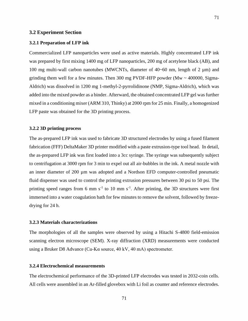
71
71
3.2 Experiment Section
3.2.1 Preparation of LFP ink
Commercialized LFP nanoparticles were used as active materials. Highly concentrated LFP ink
was prepared by first mixing 1400 mg of LFP nanoparticles, 200 mg of acetylene black (AB), and
100 mg multi-wall carbon nanotubes (MWCNTs, diameter of 40~60 nm, length of 2 µm) and
grinding them well for a few minutes. Then 300 mg PVDF-HFP powder (Mw ~ 400000, Sigma-
Aldrich) was dissolved in 1200 mg 1-methyl-2-pyrrolidinone (NMP, Sigma-Aldrich), which was
added into the mixed powder as a binder. Afterward, the obtained concentrated LFP gel was further
mixed in a conditioning mixer (ARM 310, Thinky) at 2000 rpm for 25 min. Finally, a homogenized
LFP paste was obtained for the 3D printing process.
3.2.2 3D printing process
The as-prepared LFP ink was used to fabricate 3D structured electrodes by using a fused filament
fabrication (FFF) DeltaMaker 3D printer modified with a paste extrusion-type tool head. In detail,
the as-prepared LFP ink was first loaded into a 3cc syringe. The syringe was subsequently subject
to centrifugation at 3000 rpm for 3 min to expel out all air-bubbles in the ink. A metal nozzle with
an inner diameter of 200 µm was adopted and a Nordson EFD computer-controlled pneumatic
fluid dispenser was used to control the printing extrusion pressures between 30 psi to 50 psi. The
printing speed ranges from 6 mm s-1 to 10 mm s-1. After printing, the 3D structures were first
immersed into a water coagulation bath for few minutes to remove the solvent, followed by freeze-
drying for 24 h.
3.2.3 Materials characterizations
The morphologies of all the samples were observed by using a Hitachi S-4800 field-emission
scanning electron microscope (SEM). X-ray diffraction (XRD) measurements were conducted
using a Bruker D8 Advance (Cu-Kα source, 40 kV, 40 mA) spectrometer.
3.2.4 Electrochemical measurements
The electrochemical performance of the 3D-printed LFP electrodes was tested in 2032-coin cells.
All cells were assembled in an Ar-filled glovebox with Li foil as counter and reference electrodes.

72
72
The liquid electrolyte was 1M LiPF6 dissolved in a mixture of ethylene carbonate (EC), dimethyl
carbonate (DMC), and diethyl carbonate (DEC) with a volume ratio of 1:1:1. The galvanostatic
charge-discharge performance was evaluated with a LAND test system in a voltage range of 2.5-
4.2 V (vs. Li/Li+) at room temperature.
3.3 Results and Discussion
3.3.1 Morphology and Structural Characterization
Figure 1a is a schematic illustration of the fabrication process of 3D printing self-supported LFP
electrodes. The printable LFP composite ink (Figure S1a) was prepared by first adding LFP
nanoparticles, AB and MWCNTs into PVDF-HFP/NMP to form the slurry. The high-
concentration mixture was then mixed homogeneously by a Thinky mixer prior to the printing
process. Subsequently, the obtained LFP ink was loaded into a syringe as shown in Figure S1b
and then extruded through a metal nozzle with an inner diameter of 200 µm onto a glass slide
substrate. The process was controlled by a pre-designed program. The 3D printed object together
with the glass slice substrate was then subjected to a water bath for solvent exchange. After soaking
in the water bath for few minutes, the printed structure was smoothly peeled off from the glass
substrate and a free-standing electrode with a smooth surface and improved mechanical strength
was obtained after freeze-drying for 24h. Figure 1b shows various 3D-printed complex shapes
and structures designed by a 3D-software, demonstrating that 3D printing technique has great
ability and potential in fabricating batteries with complex shapes and configurations.

73
73
Figure 3.1 a) Schematic illustration of 3D-printed self-supported LFP electrodes, and b)
Optical images of 3D-printed LFP structure with various patterns.
Since 3D printing can construct various shapes and structures, three typical circle-shaped patterns
were selected for printing LFP electrodes to explore the best electrochemical performance in coin-
cell LIBs as shown in Figure S2. The microstructures and morphologies of the three types of 3D-
printed LFP electrodes were first investigated by scanning electron microscopy (SEM) as shown
in Figure 2. Figure 2a, 2e, and 2i show the schematic of the circle-grid, circle-ring, and circle-
line pattern LFP electrodes, respectively. The microstructure of the grid-like pattern is clearly
visible in Figure 2b. The diameter of the filament is around 100 µm-150 µm, which is a little
smaller than that of the metal nozzle used for the printing. The diameter decreasing results from
the shrinkage of the polymer binder during the solvent removal step in the drying processes. It
should be noted that the decreased diameter of the dried filament might reduce the ion transport
length, thereby improving the rate performance of the electrodes. The interval between the two
filaments, which could be controlled by the printing procedure, is controlled to be around 500 µm.
The well-designed interval space was able to facilitate the diffusion of electrolyte to the active
materials. The surface of the filament is very smooth and each filament shows a very dense
structure, ensuring a high material loading density. The magnified SEM images in Figure 2c and
2d show that the LFP nanoparticles and AB nanoparticles are uniformly wrapped by the PVDF-
HFP binder, and the CNTs are interconnected between the LFP and AB nanoparticles, thus
forming an interconnected porous framework and continuous conducting network. Figure 2f and
2j show the microstructure with a ring-like pattern and line-like pattern, respectively. The
diameters of the filaments in these two patterns are similar to that of the grid pattern. The magnified
SEM images in Figure 2h and 2i also reveal that these two patterned electrodes are constructed
by the layered filaments consisting of the active material wrapped by a porous polymer framework
and conducting carbon network, thereby facilitating the ion/electron transport.

74
74
Figure 3.2 Schematic and SEM images of three types of 3D-printed LFP electrodes. a)
Schematic illustration and b, c, and d) SEM images of 3D-printed circle-grid pattern LFP
electrode. e) Schematic illustration and f, g, and h) SEM images of 3D-printed circle-ring
pattern LFP electrode. i) Schematic illustration and j, k, and l) SEM images of 3D-printed
circle-line pattern LFP electrode.
To further examine the uniform distribution of LFP nanoparticles into the printed architectures,
SEM-EDS elemental mapping was carried out as shown in Figure S3. The elemental mapping
images suggest a homogeneous distribution of C, F, Fe, P, and O in the whole structure. Figure
S4 shows the EDS spectra and corresponding elemental percentage table of the 3D-printed LFP
electrode. The atomic ratio of Fe: P: O in the printed electrode is around 0.94:1:4.3, which is very
close to the theoretical atomic ratio of Fe: P: O (1:1:4). To verify the phase stability of the LFP
during the ink preparation and freeze-drying process, X-ray diffraction (XRD) measurement was
conducted to compare the phase of pristine LFP nanoparticles and that of the 3D-printed LFP
electrodes. As presented in Figure S5, the LFP powders and 3D-printed LFP electrodes exhibit
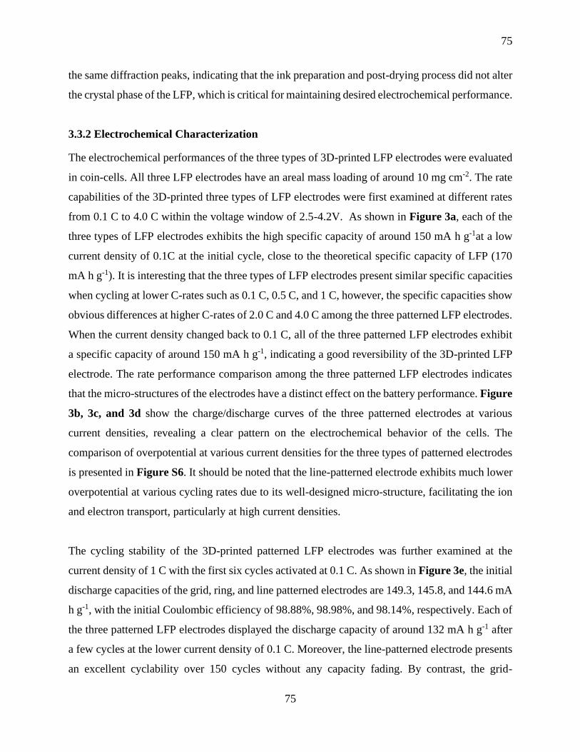
75
75
the same diffraction peaks, indicating that the ink preparation and post-drying process did not alter
the crystal phase of the LFP, which is critical for maintaining desired electrochemical performance.
3.3.2 Electrochemical Characterization
The electrochemical performances of the three types of 3D-printed LFP electrodes were evaluated
in coin-cells. All three LFP electrodes have an areal mass loading of around 10 mg cm-2. The rate
capabilities of the 3D-printed three types of LFP electrodes were first examined at different rates
from 0.1 C to 4.0 C within the voltage window of 2.5-4.2V. As shown in Figure 3a, each of the
three types of LFP electrodes exhibits the high specific capacity of around 150 mA h g-1at a low
current density of 0.1C at the initial cycle, close to the theoretical specific capacity of LFP (170
mA h g-1). It is interesting that the three types of LFP electrodes present similar specific capacities
when cycling at lower C-rates such as 0.1 C, 0.5 C, and 1 C, however, the specific capacities show
obvious differences at higher C-rates of 2.0 C and 4.0 C among the three patterned LFP electrodes.
When the current density changed back to 0.1 C, all of the three patterned LFP electrodes exhibit
a specific capacity of around 150 mA h g-1, indicating a good reversibility of the 3D-printed LFP
electrode. The rate performance comparison among the three patterned LFP electrodes indicates
that the micro-structures of the electrodes have a distinct effect on the battery performance. Figure
3b, 3c, and 3d show the charge/discharge curves of the three patterned electrodes at various
current densities, revealing a clear pattern on the electrochemical behavior of the cells. The
comparison of overpotential at various current densities for the three types of patterned electrodes
is presented in Figure S6. It should be noted that the line-patterned electrode exhibits much lower
overpotential at various cycling rates due to its well-designed micro-structure, facilitating the ion
and electron transport, particularly at high current densities.
The cycling stability of the 3D-printed patterned LFP electrodes was further examined at the
current density of 1 C with the first six cycles activated at 0.1 C. As shown in Figure 3e, the initial
discharge capacities of the grid, ring, and line patterned electrodes are 149.3, 145.8, and 144.6 mA
h g-1, with the initial Coulombic efficiency of 98.88%, 98.98%, and 98.14%, respectively. Each of
the three patterned LFP electrodes displayed the discharge capacity of around 132 mA h g-1 after
a few cycles at the lower current density of 0.1 C. Moreover, the line-patterned electrode presents
an excellent cyclability over 150 cycles without any capacity fading. By contrast, the grid-

76
76
patterned and ring-patterned electrodes deliver a discharge capacity of 102.4 and 105 mA h g-1,
demonstrating the capacity retention of 77.4% and 79.1%, respectively. This result suggests that
the line-pattern microstructure possesses more advantages over the other two patterned
microstructures, which is in accordance with the results from the rate performance comparison.
For demonstrating the advantages of 3D-printed electrodes in achieving high-performance
batteries, conventional slurry-coated thick electrodes were fabricated to compare with 3D
patterned electrodes. As observed in Figure S7a, the electrode with an areal mass loading of
around 10 mg cm-2 was prepared by using the slurry with the same composition with the printing
ink. Some cracks were observed on the electrode. When the thickness of the conventional electrode
was further increased, as demonstrated in Figure S7b, severe electrode cracking and detachment
from the Al current collector was observed. This phenomenon is common in thick electrodes
fabricated by a typical slurry coating process, can be attributed to the weak adhesion between the
electrode components and metal current collectors and the shrinkage of the electrode materials
during the drying process, which causes a failure to maintain the electrode structural integrity.11,
27-28 The ease of deformation of the conventional thick electrode leads to the shorter cycle life and
poor safety. As shown in Figure S7c, the conventional thick electrode with an areal mass loading
of around 10 mg cm-2 exhibits an initial discharge capacity of approximately 124 mA h g-1 with a
dramatic capacity fade occurring with a capacity retention of 51.8% after 115 cycles. This
comparison clearly indicates that all the 3D-printed patterned electrodes show an improved
specific capacity and cycling stability compared to the performance of the conventional thick
electrode. The enhanced electrochemical performance of 3D-printed electrodes can be ascribed to
the micro-scaled and nano-scaled multi-channeled architecture, which allows for fast lithium ion
diffusion and efficient electrolyte penetration. In addition, the superior mechanical structure
stability of the 3D-printed patterned electrodes is also a factor that contributes to the enhanced
cycling stability.

77
77
Figure 3.3 Electrochemical performance of the three types of 3D-printed LFP electrodes. a)
Comparison of rate performance of the three types of LFP electrodes. Charge-discharge
voltage curves of b) 3D-printed grid pattern, c) 3D-printed ring pattern and d) 3D-printed
line pattern LFP electrodes at various rates. e) Cycling performance of the three types of
LFP electrodes at 1C with the first six cycles activated at 0.1 C.
To further consider the superiorities of the 3D printing technique in building high-performance
thick electrodes for LIBs, a series of line-pattern LFP electrodes with different thickness were
fabricated by the 3D printing method. Figure S8 shows four 3D-patterned electrodes with different
printing layers (2 layers, 4 layers, 6 layers, and 8 layers) on the same glass slice substrate before
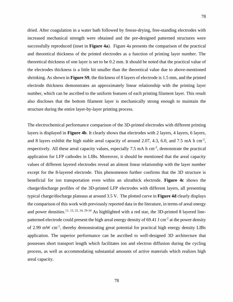
78
78
dried. After coagulation in a water bath followed by freeze-drying, free-standing electrodes with
increased mechanical strength were obtained and the pre-designed patterned structures were
successfully reproduced (inset in Figure 4a). Figure 4a presents the comparison of the practical
and theoretical thickness of the printed electrodes as a function of printing layer number. The
theoretical thickness of one layer is set to be 0.2 mm. It should be noted that the practical value of
the electrodes thickness is a little bit smaller than the theoretical value due to above-mentioned
shrinking. As shown in Figure S9, the thickness of 8 layers of electrode is 1.5 mm, and the printed
electrode thickness demonstrates an approximately linear relationship with the printing layer
number, which can be ascribed to the uniform features of each printing filament layer. This result
also discloses that the bottom filament layer is mechanically strong enough to maintain the
structure during the entire layer-by-layer printing process.
The electrochemical performance comparison of the 3D-printed electrodes with different printing
layers is displayed in Figure 4b. It clearly shows that electrodes with 2 layers, 4 layers, 6 layers,
and 8 layers exhibit the high stable areal capacity of around 2.07, 4.3, 6.0, and 7.5 mA h cm-2,
respectively. All these areal capacity values, especially 7.5 mA h cm-2, demonstrate the practical
application for LFP cathodes in LIBs. Moreover, it should be mentioned that the areal capacity
values of different layered electrodes reveal an almost linear relationship with the layer number
except for the 8-layered electrode. This phenomenon further confirms that the 3D structure is
beneficial for ion transportation even within an ultrathick electrode. Figure 4c shows the
charge/discharge profiles of the 3D-printed LFP electrodes with different layers, all presenting
typical charge/discharge plateaus at around 3.5 V. The plotted curve in Figure 4d clearly displays
the comparison of this work with previously reported data in the literature, in terms of areal energy
and power densities.11, 13, 22, 24, 29-34 As highlighted with a red star, the 3D-printed 8 layered line-
patterned electrode could present the high areal energy density of 69.41 J cm-2 at the power density
of 2.99 mW cm-2, thereby demonstrating great potential for practical high energy density LIBs
application. The superior performance can be ascribed to well-designed 3D architecture that
possesses short transport length which facilitates ion and electron diffusion during the cycling
process, as well as accommodating substantial amounts of active materials which realizes high
areal capacity.

79
79
Figure 3.4 a) Practical and theoretical thickness of the 3D-printed electrodes as a function of
the printing layer number (inset: optical images of 3D-printed electrodes with different
printing layers). b) Comparison of the areal capacity of the LFP electrodes with different
layer numbers. c) Charge/discharge profiles of the LFP electrodes with different layer
numbers. d) Comparison of power density and energy density of this work with previously
reported values.
3D electrodes with well-designed architectures via 3D printing technique has been proven to show
many advantages over conventional slurry-coated flat electrodes in terms of delivering enhanced
areal energy density, better power density, and cycling stability. As illustrated in Figure 5,
although high power density can be achieved with a short ion transport distance, conventional thin
electrodes can only deliver the low energy density as it lacks active materials. When a thick
electrode is constructed by the conventional slurry coating method, the high energy density could
be realized, however, the power density would be greatly restricted as the ion transport distance
increases substantially. To this end, 3D electrodes can realize a trade-off between the high energy
density and power density by maintaining a short and uniform ion diffusion path, ensuring that the

80
80
thick electrode can achieve high power density. Compared to previous 3D-printed LFP, this work
demonstrates greatly improved power and energy density due to the optimized 3D printing process
as well as the geometric considerations. This work also demonstrates that 3D-printed electrodes
can realize the highest level of areal loading comparing to other advanced 3D electrode
manufacturing methods.
Figure 3.5 Schematic illustration of the comparison between ultra-thick a) traditional
electrodes and b) 3D electrodes.
3.4 Conclusion
3D patterned self-supported thick electrodes for high areal energy and power density LIBs were
realized by an optimized extrusion-type 3D printing technique. The resulting unique 3D structured
electrodes were constructed by continuous layer-by-layer filaments composed of interconnected
porous polymer frameworks and continuous conducting carbon networks, thereby greatly
improving ion and electron transport. The well-designed 3D micro-structures were demonstrated
to increase the surface area and maintain a short ion transport distance even within a thick electrode,
facilitating the electrolyte penetration into the active materials as well as ion/electron diffusion.
Due to these structural merits, the 3D-patterned electrodes exhibited superior electrochemical
performance over conventional thick flat electrodes in terms of specific capacity and cycling
stability. Moreover, an ultrathick electrode of 1500 µm 3D electrodes with 8 printed layers was
81
81
fabricated and presented a high areal capacity of approximately 7.5 mA h cm-2 and energy density
of 69.41 J cm-2 at a power density of 2.99 mW cm-2, demonstrating comparable values with
reported high-performance LFP cathodes fabricated by both 3D printing and other methods in
literature. This work thus provides a facile, low cost, and easily scaled way to fabricate high areal
loading/thick electrode to achieve high areal energy density with high power density, which holds
great promise for future practical application of high energy density lithium-ion batteries.
Acknowledgements
The work was supported by Natural Science Foundation of China (NSFC) (Grant U1432249), the
National Key R&D Program of China (Grant 2017YFA0205002), and the Priority Academic
Program Development (PAPD) of Jiangsu Higher Education Institutions. This is also a project
supported by Jiangsu Key Laboratory for Carbon-Based Functional Materials and Devices and the
Collaborative Innovation Center of Suzhou Nano Science & Technology. This work was also
supported by the Natural Science and Engineering Research Council of Canada (NSERC), the
Canada Research Chair Program (CRC), the Canada Foundation for Innovation (CFI), and the
University of Western Ontario (UWO).
3.5 References
1. Lu, L.; Han, X.; Li, J.; Hua, J.; Ouyang, M., A Review On The Key Issues For Lithium-
Ion Battery Management In Electric Vehicles. J. Power Sources 2013, 226, 272-288.
2. Nitta, N.; Wu, F.; Lee, J. T.; Yushin, G., Li-Ion Battery Materials: Present and Future.
Mater. Today 2015, 18, 252-264.
3. Tarascon, J. M.; Armand, M., Issues and Challenges Facing Rechargeable Lithium
Batteries. Nature 2001, 414, 359-367.
4. Wang, J.; Sun, X., Olivine LiFePO4: The Remaining Challenges for Future Energy Storage.
Energy Environ. Sci. 2015, 8, 1110-1138.

82
82
5. Gao, X.; Wang, J.; Zhang, D.; Nie, K.; Ma, Y.; Zhong, J.; Sun, X., Hollow NiFe2O4
Nanospheres on Carbon Nanorods as A Highly Efficient Anode Material for Lithium-Ion Batteries.
J. Mater. Chem. A 2017, 5, 5007-5012.
6. Li, X.; Gu, M.; Hu, S.; Kennard, R.; Yan, P.; Chen, X.; Wang, C.; Sailor, M. J.; Zhang, J.-
G.; Liu, J., Mesoporous Silicon Sponge as An Anti-Pulverization Structure for High-Performance
Lithium-Ion Battery Anodes. Nat. Commun. 2014, 5, 4105-4112.
7. Gao, X.; Wang, J.; Zhang, D.; Adair, K.; Feng, K.; Sun, N.; Zheng, H.; Shao, H.; Zhong,
J.; Ma, Y.; Sun, X.; Sun, X., Carbon Coated Bimetallic Sulfide Nanodots/Carbon Nanorod
Heterostructure Enabling Long-Life Lithium-Ion Batteries. J. Mater. Chem. A 2017, 5, 25625-
25631.
8. Gallagher, K. G.; Trask, S. E.; Bauer, C.; Woehrle, T.; Lux, S. F.; Tschech, M.; Lamp, P.;
Polzin, B. J.; Ha, S.; Long, B.; Wu, Q.; Lu, W.; Dees, D. W.; Jansen, A. N., Optimizing Areal
Capacities Through Understanding the Limitations of Lithium-Ion Electrodes. J. Electrochem. Soc.
2015, 163, A138-A149.
9. Song, J.; Sen, X.; Linjun, W.; Zhenzhen, D.; Lina, C.; Jiafeng, C.; Xianghua, K.; Ming, G.;
Junling, L.; Yanwu, Z.; Hengxing, J.; S., R. R., Covalently Connected Carbon Nanostructures for
Current Collectors in Both the Cathode and Anode of Li–S Batteries. Adv. Mater. 2016, 28, 9094-
9102.
10. Park, J.; Li, J.; Lu, W.; Sastry, A. M., Geometric Consideration of Nanostructures for
Energy Storage Systems. J. Appl. Phys. 2016, 119, 025101.
11. Chen, C.; Zhang, Y.; Li, Y.; Kuang, Y.; Song, J.; Luo, W.; Wang, Y.; Yao, Y.; Pastel, G.;
Xie, J.; Hu, L., Highly Conductive, Lightweight, Low-Tortuosity Carbon Frameworks as
Ultrathick 3D Current Collectors. Adv. Energy Mater. 7, 1700595.
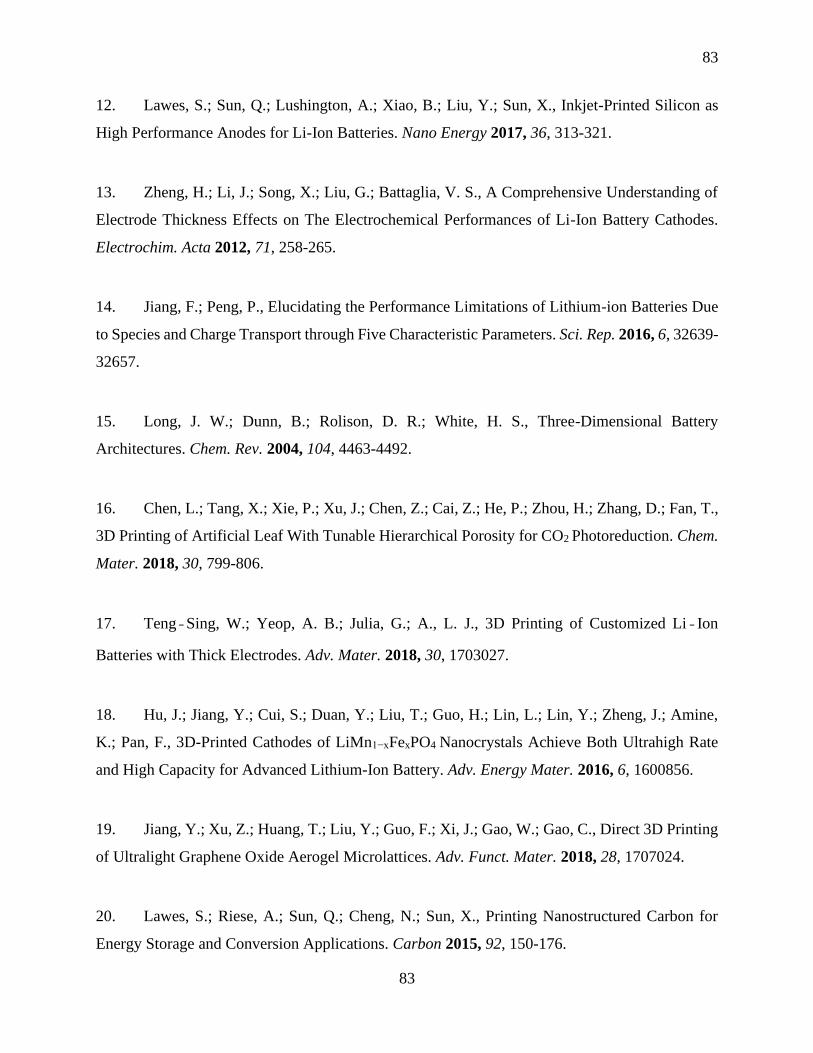
83
83
12. Lawes, S.; Sun, Q.; Lushington, A.; Xiao, B.; Liu, Y.; Sun, X., Inkjet-Printed Silicon as
High Performance Anodes for Li-Ion Batteries. Nano Energy 2017, 36, 313-321.
13. Zheng, H.; Li, J.; Song, X.; Liu, G.; Battaglia, V. S., A Comprehensive Understanding of
Electrode Thickness Effects on The Electrochemical Performances of Li-Ion Battery Cathodes.
Electrochim. Acta 2012, 71, 258-265.
14. Jiang, F.; Peng, P., Elucidating the Performance Limitations of Lithium-ion Batteries Due
to Species and Charge Transport through Five Characteristic Parameters. Sci. Rep. 2016, 6, 32639-
32657.
15. Long, J. W.; Dunn, B.; Rolison, D. R.; White, H. S., Three-Dimensional Battery
Architectures. Chem. Rev. 2004, 104, 4463-4492.
16. Chen, L.; Tang, X.; Xie, P.; Xu, J.; Chen, Z.; Cai, Z.; He, P.; Zhou, H.; Zhang, D.; Fan, T.,
3D Printing of Artificial Leaf With Tunable Hierarchical Porosity for CO2 Photoreduction. Chem.
Mater. 2018, 30, 799-806.
17. Teng‐Sing, W.; Yeop, A. B.; Julia, G.; A., L. J., 3D Printing of Customized Li‐Ion
Batteries with Thick Electrodes. Adv. Mater. 2018, 30, 1703027.
18. Hu, J.; Jiang, Y.; Cui, S.; Duan, Y.; Liu, T.; Guo, H.; Lin, L.; Lin, Y.; Zheng, J.; Amine,
K.; Pan, F., 3D-Printed Cathodes of LiMn1−xFexPO4 Nanocrystals Achieve Both Ultrahigh Rate
and High Capacity for Advanced Lithium-Ion Battery. Adv. Energy Mater. 2016, 6, 1600856.
19. Jiang, Y.; Xu, Z.; Huang, T.; Liu, Y.; Guo, F.; Xi, J.; Gao, W.; Gao, C., Direct 3D Printing
of Ultralight Graphene Oxide Aerogel Microlattices. Adv. Funct. Mater. 2018, 28, 1707024.
20. Lawes, S.; Riese, A.; Sun, Q.; Cheng, N.; Sun, X., Printing Nanostructured Carbon for
Energy Storage and Conversion Applications. Carbon 2015, 92, 150-176.

84
84
21. Collin, L.; Ju-Hee, S.; John, M.; D., D. M., 3D Printing of Free Standing Liquid Metal
Microstructures. Adv. Mater. 2013, 25, 5081-5085.
22. Li, J.; Leu, M. C.; Panat, R.; Park, J., A Hybrid Three-Dimensionally Structured Electrode
for Lithium-Ion Batteries via 3D Printing. Mater. Design 2017, 119, 417-424.
23. Choi, K.-H.; Ahn, D. B.; Lee, S.-Y., Current Status and Challenges in Printed Batteries:
Toward Form Factor-Free, Monolithic Integrated Power Sources. ACS Energy Lett. 2017, 3, 220-
236.
24. Sun, K.; Wei, T. S.; Ahn, B. Y.; Seo, J. Y.; Dillon, S. J.; Lewis, J. A., 3D printing of
Interdigitated Li-Ion Microbattery Architectures. Adv. Mater. 2013, 25, 4539-4543.
25. Fu, K.; Wang, Y.; Yan, C.; Yao, Y.; Chen, Y.; Dai, J.; Lacey, S.; Wang, Y.; Wan, J.; Li,
T.; Wang, Z.; Xu, Y.; Hu, L., Graphene Oxide-Based Electrode Inks for 3D-Printed Lithium-Ion
Batteries. Adv. Mater. 2016, 28, 2587-2594.
26. Ding, J.; Shen, K.; Du, Z.; Li, B.; Yang, S., 3D-Printed Hierarchical Porous Frameworks
for Sodium Storage. ACS Appl. Mater. Interfaces 2017, 9, 41871-41877.
27. Sung‐Ju, C.; Keun‐Ho, C.; Jong‐Tae, Y.; Jeong‐Hun, K.; Yong‐Hyeok, L.; Sang‐Jin, C.;
Sang‐Bum, P.; Don‐Ha, C.; Qinglin, W.; Sun‐Young, L.; Sang‐Young, L., Hetero‐Nanonet
Rechargeable Paper Batteries: Toward Ultrahigh Energy Density and Origami Foldability. Adv.
Funct. Mater. 2015, 25, 6029-6040.
28. Evanoff, K.; Khan, J.; Balandin, A. A.; Magasinski, A.; Ready, W. J.; Fuller, T. F.; Yushin,
G., Towards Ultrathick Battery Electrodes: Aligned Carbon Nanotube-Enabled Architecture. Adv.
Mater. 2012, 24, 533-537.

85
85
29. Liu, C.; Cheng, X.; Li, B.; Chen, Z.; Mi, S.; Lao, C., Fabrication and Characterization of
3D-Printed Highly-Porous 3D LiFePO4 Electrodes by Low Temperature Direct Writing Process.
Materials 2017, 10, 934-947.
30. Shaijumon, M. M.; Perre, E.; Daffos, B.; Taberna, P. L.; Tarascon, J. M.; Simon, P.,
Nanoarchitectured 3D Cathodes for Li-Ion Microbatteries. Adv. Mater. 2010, 22, 4978-4981.
31. Kohlmeyer, R. R.; Blake, A. J.; Hardin, J. O.; Carmona, E. A.; Carpena-Núñez, J.;
Maruyama, B.; Daniel Berrigan, J.; Huang, H.; Durstock, M. F., Composite Batteries: A Simple
yet Universal Approach to 3D Printable Lithium-Ion Battery Electrodes. J. Mater. Chem. A 2016,
4, 16856-16864.
32. Li, J.; Liang, X.; Liou, F.; Park, J., Macro-/Micro-Controlled 3D Lithium-Ion Batteries via
Additive Manufacturing and Electric Field Processing. Sci. Rep. 2018, 8, 1846-1857.
33. Gao, L.; Jin, Y.; Liu, X.; Xu, M.; Lai, X.; Shui, J., A Rationally Assembled Graphene
Nanoribbon/Graphene Framework for High Volumetric Energy and Power Density Li-Ion
Batteries. Nanoscale 2018, 10, 7676-7684.
34. Hur, J. I.; Smith, L. C.; Dunn, B., High Areal Energy Density 3D Lithium-Ion
Microbatteries. Joule 2018, 2, 1187-1201.
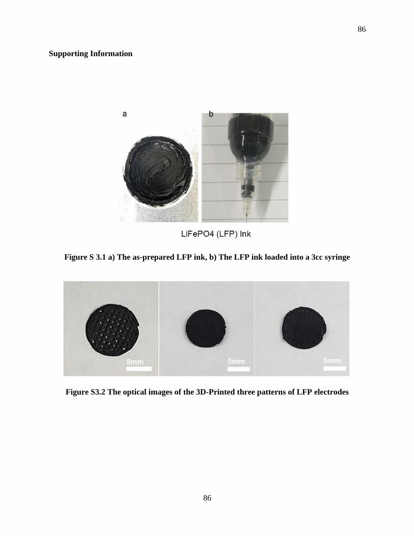
86
86
Supporting Information
Figure S 3.1 a) The as-prepared LFP ink, b) The LFP ink loaded into a 3cc syringe
Figure S3.2 The optical images of the 3D-Printed three patterns of LFP electrodes

87
87
Figure S3.3 (a) SEM image and (b-f) corresponding C, F, Fe, P, and O element mapping
images of the 3D-printed LFP electrode
Figure S3.4 a) EDS spectra of the 3D-printed LFP electrode and its corresponding b) EDS
elemental percentage table
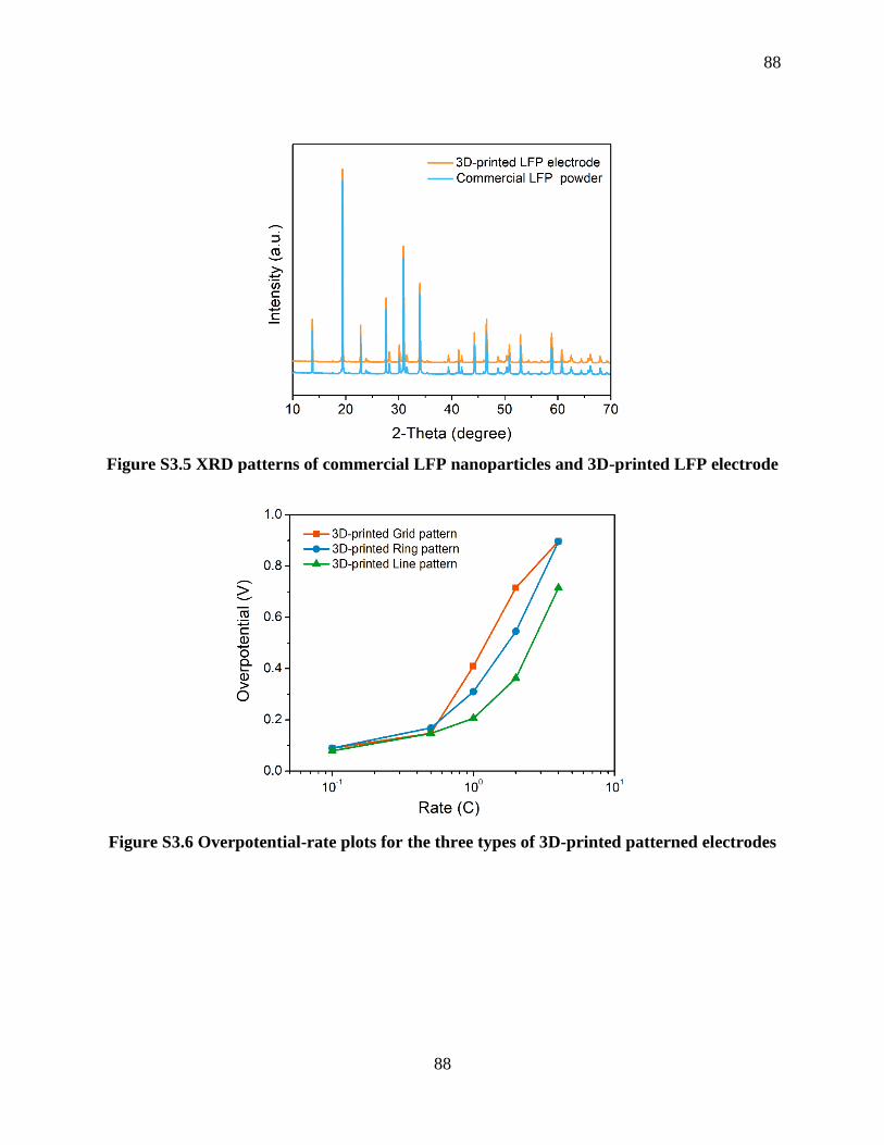
88
88
Figure S3.5 XRD patterns of commercial LFP nanoparticles and 3D-printed LFP electrode
Figure S3.6 Overpotential-rate plots for the three types of 3D-printed patterned electrodes

89
89
Figure S3.7 a) LFP electrode with a loading amount of around 10mg cm-2, b) LFP electrode
with a loading amount of around 15mg cm-2 prepared by a traditional blade-casting method,
and c) LFP cycling performance at a current of 1C rate
Figure S3.8 3D-printed LFP electrodes with different layers on a glass-slice substrate before
dried

90
90
Figure S3.9 Measurement of the thickness of 8-layers patterned electrode

91
91
Chapter 4
4 3D Printing of Vertically Aligned and Patternable Silicon Anodes for High Areal
Capacity Li-Ion Batteries
Silicon has been regarded as one of the most promising anode materials because of its high specific
capacity. However, the main challenges associated with Si anodes: namely the huge volume
expansion of Si and poor electrical conductivity, can result in a short battery cycle life. Moreover,
the fatal disadvantage caused by large volume change is exacerbated under high Si mass loading.
Herein for the first time, we developed a facile 3D printing approach to rapidly construct
patternable and hierarchically porous Si architecture. The 3D-printed Si electrodes designed
possess vertically aligned mass/ionic transport pathways and macro/micro-scaled porosities,
which can facilitate electron/ion transport within the entire electrodes and effectively mitigates
the huge volume expansion expected during cycling. As a result, these electrodes exhibited a
reversible high areal capacity of around 3 mAh cm-2 (corresponding to a specific capacity of 1450
mAh g-1). Moreover, even under a high mass loading of 3.81 mg cm-2, the electrodes display an
extremely high initial areal capacity of 10.31 mAh cm-2 (corresponding to a specific capacity of
2706.04 mAh g-1). This work thus opens a new and promising avenue for constructing novel 3D
architectures for advanced energy systems.

92
92
4.1 Introduction
Nowadays, lithium-ion batteries (LIBs) with high energy densities are highly desired for powering
consumer electronics and electric vehicles.1-3 Silicon (Si) anodes have thus attracted tremendous
interest in the past decades due to their high specific capacity (around 4200 mAh g-1), low cost,
and relatively low discharge potential (≈0.4V versus Li+/Li). Despite possessing these
distinguishing features, Si anodes have several intrinsic obstacles, namely huge volume expansion
(nearly 400%) during the cycling process and poor electrical conductivity, which cause fast
capacity fading, thereby greatly restricting their practical application.4-5
Hitherto, numerous efforts have been made to address the aforementioned challenges, which can
be classified into three main categories: 1) design of various nanostructured and porous silicon to
alleviate the large volume change such as Si nanowire,6-7 Si nanotubes,8 mesoporous Si,9 and
hollow particles.10 2) Development of varied carbon-based composites (graphene-Si, CNT-Si,
carbon nanosheets-Si) to enhance the overall electrical conductivity.11-12 3) Design of multi-
functional binders to enhance structural integrity.13-14 However, these strategies are either too
complex and expensive or can hardly realize a desirable areal capacity. It is critical to develop a
facile and low-cost approach in order to realize stable and high areal capacity Si anodes that can
meet the requirements for practical application.
Recently 3D printing, as an advanced additive manufacturing (AM) technique, has gained large
scale attention for its capabilities in the fabrication of complex 3D structures and geometric shapes
from various materials - and has been widely used in a wide range of areas, including biomedical
fields15-16 as well as the fabrication of electronics17-18, catalysis19-21, and energy storage and
conversion devices22-23. For instance, Hu and co-workers24 constructed a 3D holey graphene oxide
(hGO) mesh with multiple levels of porosity (macroscale to nanoscale) through an extrusion-based
printing technique. The printed 3D hGO electrode exhibited superior Li-O2 battery performance
due to the designed hierarchical porous architectures. More recently, Fan and co-workers25
employed 3D-printing in constructing a leaf-inspired architected graphene/Ni0.33Co0.66S2 aerogel
where the resultant structures allowed rapid electron/ion transport, thus leading to superior
electrochemical performance. These previous works demonstrate that 3D printing shows a
93
93
promising role in the manufacture of novel 3D architectures, which could provide new avenues
for solving the major challenges associated with Si anodes.
Herein, for the first time, we construct a 3D vertically aligned structure with multi-scaled porosities
(denoted as 3D-VLMP) for silicon anodes using extrusion-based direct-ink-writing (DIW) 3D
printing techniques, assisted with a freeze-drying post-treatment. The designed structure has
multiple strengths: (1) the hierarchically porous 3D architecture enables electrode structural
integrity, (2) the multiple levels of porosity (macro to micro) provides free space to accommodate
the huge volume expansion of Si during repeated cycles and facilitates the access of electrolyte
into the active materials, (3) the vertical walls constructing the micropores allows continuous and
fast electron/ion transport pathways, (4) the interwoven filaments consisting of CNTs act as a high-
performance electrical network. Thus, the 3D-VLMP Si electrode is able to exhibit a high areal
capacity of around 3 mAh cm-2 (corresponding to a specific capacity of 1450 mAh g-1) after 60
cycles. Moreover, even under a high mass loading of 3.81 mg cm-2, the electrode can display an
extremely high initial areal capacity of 10.31 mAh cm-2 (corresponding to a specific capacity of
2706.04 mAh g-1). This work thus opens a new and promising avenue for constructing novel 3D
architectures for advanced energy systems.
4.2 Experimental Section
4.2.1 Si-SA Ink Preparation
Si-SA ink was prepared by mixing 350 mg of Si nanoparticles, 140 mg of multi-wall carbon
nanotubes (MWCNTs, the diameter of 40-60 nm, length of 2 um), and 70 mg of acetylene black
(AB) and then grinding them well by hand for a few minutes. Sodium alginate (SA) solution (2.8
g, 5 wt%) was then added to the mixed powders as an aqueous binder. After that, the composites
were further mixed in a conditioning mixer (ARM, Thinky) at 2000 rpm for 40 minutes to obtain
a homogenous and viscous ink. Finally, the obtained Si-SA ink was loaded into a 3cc syringe for
printing.
94
94
4.2.2 3D Printing Process
The 3D printing process was conducted on a fused filament fabrication (FFF) DeltaMaker 3D
printer modified with a paste extrusion-type tool head. The syringe with Si-SA ink was subject to
centrifugation at 3000 rpm for 3 minutes to expel out the air-bubbles prior to the printing process.
A Nordson EFD computer-controlled pneumatic fluid dispenser provides the appropriate pressure
to extrude the ink through a metal nozzle with an inner diameter of 200 um and control the flow
rate. The printing speed ranges from 6 mm s-1 to 10 mm s-1 depending on the printing pressure and
ink viscosity. The 3D structures were printed directly on the Cu foil. The printed 3D Si electrodes
were post-treated in two ways: one was directly dried in air. The other was freeze-dried for 24h to
obtain the designed 3D architecture.
4.2.3 Materials characterizations
The morphologies of all the samples were observed by using a Hitachi S-4800 field-emission
scanning electron microscope (SEM). Fourier-transform infrared spectroscopy (FTIR) spectra
were collected by a Nicolet 6700 FTIR spectrometer. Raman spectra were collected on a HORIBA
Scientific LabRAM Raman spectrometer equipped with a 532.03 nm laser.
4.2.4 Electrochemical Measurements
The electrochemical performance of the 3D-printed Si electrodes was tested in CR 2032-coin cells.
All cells were assembled in an Ar-filled glovebox with Li foil as the counter and reference
electrodes. The liquid electrolyte was 1M LiPF6 dissolved in a mixture of ethylene carbonate (EC)
and diethyl carbonate (DEC) (1:1, by volume) containing 10% fluoroethylene carbonate (FEC).
The galvanostatic charge-discharge performance was evaluated with a LAND test system within
a voltage range of 0.01-1.5 V (vs. Li/Li+) at room temperature.
4.3 Results and Discussion
4.3.1 Morphology and Structure Characterization

95
95
Figure 4.1. Fabrication process and material characterization of the 3D-VLMP Si electrode.
(a) Schematic illustration of 3D printing of vertically aligned silicon electrodes with multiple
levels of porosities. (b to e) SEM images of the 3D-VLMP Si electrodes under different
magnifications; (f and g) SEM image and corresponding EDX mappings of the 3D-VLMP Si
electrode.
The 3D patterned silicon electrodes with vertically aligned architecture and multiple levels of
porosities were fabricated through a paste-extrusion type 3D printing method combined with a
freeze-drying post-printing treatment as illustrated in Figure 4.1a. To obtain a printable ink for
the DIW process, highly concentrated sodium alginate (SA) solution (5 wt %) was used as an
aqueous binder to get a proper Si-SA ink with a suitable viscosity. The detailed ink preparation
process can be found in the experimental section. The obtained homogeneous and highly viscous
Si-SA ink was then transferred into a 3cc syringe for printing (Figure S4.1). The ink was then
extruded through a metal nozzle onto the Cu foil controlled by a pre-designed program.

96
96
Subsequently, the as-printed Si electrode was freeze-dried for 24h to obtain the desired 3D
microstructure.
The microstructures and morphologies of the as-printed vertically aligned Si electrodes were first
investigated by scanning electron microscopy (SEM). Figure 4.1b is a top-down SEM image of
the 3D-VLMP Si electrode taken directly after the printing and freeze-drying procedures. It is clear
that the 3D architecture with well-defined and interconnected macropores was well maintained.
The 3D architecture was constructed from continuous and interwoven filaments with a diameter
of around 150-200 µm. 3D architecture can enable excellent structural integrity without cracking.
In contrast, as shown in Figure S4.2, the conventional slurry-coated 2D flat Si electrodes
demonstrated severe cracking due to the huge amounts of stresses generated during the drying
process. Figure 4.1c is an enlarged SEM image where it can be seen that the size of a macropore
is around 150 µm (from 3D design) and numerous micropores (tens of micrometers) were
generated from the freeze-drying process as observable on the filaments of the 3D architecture.
More interestingly, the micropores are formed out of the vertical-wall structures consisting of 1D
carbon nanotubes, 0D Si nanoparticles, and aqueous-based SA binder, as displayed in Figure 4.1d.
Figure 4.1e shows the detailed morphology of the filaments. As observed from the magnified
SEM image, CNTs are interconnected with Si and AB nanoparticles, forming nano-scaled pores
and a continuous conducting network, which is beneficial for the electron/ion transport within the
whole electrode. SEM elemental mapping was carried out to determine the distribution of Si
nanoparticles in the printed architectures, as shown in Figure 4.1f and 4.1g. The elemental
mapping images of the printed Si electrode display a uniform distribution of Si, C, Na, and O
throughout the whole structure.
Raman spectroscopy measurement was further conducted to gain insight into the composition of
the printed Si electrodes. As depicted in Figure S4.3, Raman spectroscopy shows four
characteristic peaks, the sharp peak located at 505 cm-1 is attributed to the Si-Si vibrational
stretching mode in crystalline Si. Another two peaks (demonstrated in the inset image, Figure S3)
at around 1338 and 1597 cm-1 can be assigned to the D and G bands of CNT. The peak intensity
ratio of the IG/ID is around 1.02 , indicating the CNT has a crystalline structure.26 Figure S4.4 is
the FTIR spectra of the printed Si electrodes, which shows typical bands of around 3440 and 1615
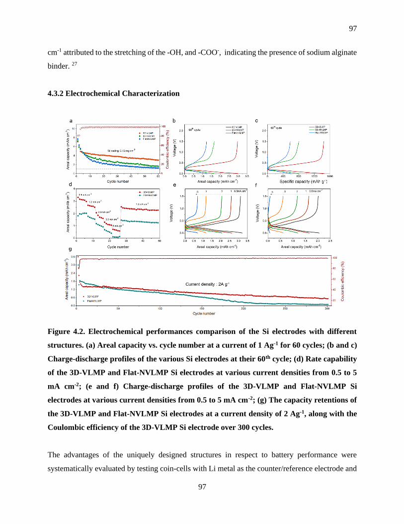
97
97
cm-1 attributed to the stretching of the -OH, and -COO-, indicating the presence of sodium alginate
binder. 27
4.3.2 Electrochemical Characterization
Figure 4.2. Electrochemical performances comparison of the Si electrodes with different
structures. (a) Areal capacity vs. cycle number at a current of 1 Ag-1 for 60 cycles; (b and c)
Charge-discharge profiles of the various Si electrodes at their 60th cycle; (d) Rate capability
of the 3D-VLMP and Flat-NVLMP Si electrodes at various current densities from 0.5 to 5
mA cm-2; (e and f) Charge-discharge profiles of the 3D-VLMP and Flat-NVLMP Si
electrodes at various current densities from 0.5 to 5 mA cm-2; (g) The capacity retentions of
the 3D-VLMP and Flat-NVLMP Si electrodes at a current density of 2 Ag-1, along with the
Coulombic efficiency of the 3D-VLMP Si electrode over 300 cycles.
The advantages of the uniquely designed structures in respect to battery performance were
systematically evaluated by testing coin-cells with Li metal as the counter/reference electrode and

98
98
the 3D printed Si electrode as the working electrode. Figure 4.2a and Figure S4.6 shows the
cycling performance comparison of the Si electrodes among three different structures. All three Si
electrodes were prepared under an areal mass loading of around 2.12 mg cm-2 to meet the
performance level of commercial lithium-ion batteries (over 3 mAh cm-2). In the first cycle, each
Si electrode exhibited a high areal capacity of over 7 mAh cm-2 at a lower current density of 0.3 A
g-1. However, the capacity retention from the 2nd cycle to the 60th cycle was distinctly different
among the three Si electrodes. As shown in Figure 4.2c and 4.2c, the 3D-VLMP Si electrode
displayed the highest areal capacity of around 3.01 mAh cm-2 (1467.2 mAh g-1) after 60 cycles. In
contrast, the 3D printed and non-vertically aligned Si electrode without micro-pore structures
(denoted as 3D-NVLMP Si) delivered relatively lower areal capacity of 1.67 mAh cm-2 (814.4
mAh g-1), whereas the conventional slurry-coated non-vertically aligned Si electrode without pores
(Flat-NVLMP Si) only obtained an areal capacity of 1.24 mAh cm-2 (582.5 mAh g-1)
corresponding to a capacity retention of only 16.07% against the initial cycle. This comparison
suggests that the 3D vertically aligned and macro/micro porous architecture can effectively help
accommodate the severe volume change during the lithiation/delithiation process, leading to
superior cycling stability. To further demonstrate the benefits of the designed 3D-VLMP structures,
we compared the rate capabilities of the 3D-VLMP and Flat-NVLMP Si electrodes at various
current densities from 0.5 to 5 mA cm-2. As displayed in Figure 4.2d and Figure S4.7, the 3D-
VLMP Si electrode exhibited superb rate capabilities compared to that of the Flat-NVLMP Si
electrode as the current density was varied from 0.5 to 5 mA cm-2. Even at a high current density
of 5 mA cm-2, the 3D-VLMP Si electrode was able to deliver an areal capacity of 0.68 mAh cm-2
(579.5 mAh g-1) while the Flat-NVLMP Si only achieved an areal capacity of 0.09 mAh cm-2 (103
mAh g-1). Moreover, when the current density changed back to 1 mA cm-2, the 3D-VLMP Si
exhibited an excellent specific capacity of around 2000 mAh g-1(corresponding to 2.35 mAh cm-
2), whereas the specific capacity of the Flat-NVLMP Si is less than 1600 mAh g-1. Figure 4.2e and
4.2f are the voltage profiles of the 3D-VLMP and Flat-NVLMP Si electrodes, respectively. It is
clear that the 3D-VLMP Si obtained a smaller overpotential, especially at high current densities
compared to that of the Flat-NVMP Si, indicating that the designed 3D-VLMP architecture could
greatly help facilitate the Li+ transport within the whole electrode. Furthermore, as shown in
Figure 4.2g, the 3D-VLMP Si electrodes exhibited superior capacity retention at a high current
density of 2A g-1 after 300 cycles.

99
99
Figure 4.3. Performance metrics for 3D-VLMP Si electrodes with high areal mass loading.
(a) Schematic illustration of the 3D-printed VLMP Si electrodes with different thickness and
mass loadings; (b) Comparison of the electrochemical impedance of the 3D-VLMP Si
electrodes with different mass loadings; (c). Various areal mass loading tests (up to 3.81 mg
cm-2) of the printed 3D-VLMP Si electrodes. All electrodes were cycled at 0.3 mA cm-2 for
the initial cycle up to 1.0 mA cm-2 for the later cycles. (d). Areal capacity of the 3D-VLMP Si
electrodes with different mass loading at the 1st, 20th, and 40th cycle, respectively; (e).
Comparison of areal performance between the 3D VLMP Si electrodes with Si anodes as
reported in other works, as noted.
High areal mass loading is crucial to achieving high-performance EES systems in practical
application. However, many reported works only studied the low-Si mass loadings in order to
achieve a long cycling life of their Si electrodes,28-29 hence, it can be deduced that there is a
considerable challenge to realize a desirable performance under high areal mass loading. We
therefore fabricated a series of 3D-VLMP Si electrodes with different areal mass loadings up to
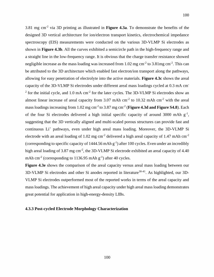
100
100
3.81 mg cm-2 via 3D printing as illustrated in Figure 4.3a. To demonstrate the benefits of the
designed 3D vertical architecture for ion/electron transport kinetics, electrochemical impedance
spectroscopy (EIS) measurements were conducted on the various 3D-VLMP Si electrodes as
shown in Figure 4.3b. All the curves exhibited a semicircle path in the high-frequency range and
a straight line in the low-frequency range. It is obvious that the charge transfer resistance showed
negligible increase as the mass loading was increased from 1.02 mg cm-2 to 3.81mg cm-2. This can
be attributed to the 3D architecture which enabled fast electron/ion transport along the pathways,
allowing for easy penetration of electrolyte into the active materials. Figure 4.3c shows the areal
capacity of the 3D-VLMP Si electrodes under different areal mass loadings cycled at 0.3 mA cm-
2 for the initial cycle, and 1.0 mA cm-2 for the later cycles. The 3D-VLMP Si electrodes show an
almost linear increase of areal capacity from 3.07 mAh cm-2 to 10.32 mAh cm-2 with the areal
mass loadings increasing from 1.02 mg cm-2 to 3.87 mg cm-2 (Figure 4.3d and Figure S4.8). Each
of the four Si electrodes delivered a high initial specific capacity of around 3000 mAh g-1,
suggesting that the 3D vertically aligned and multi-scaled porous structures can provide fast and
continuous Li+ pathways, even under high areal mass loading. Moreover, the 3D-VLMP Si
electrode with an areal loading of 1.02 mg cm-2 delivered a high areal capacity of 1.47 mAh cm-2
(corresponding to specific capacity of 1444.56 mAh g-1) after 100 cycles. Even under an incredibly
high areal loading of 3.87 mg cm-2, the 3D-VLMP Si electrode exhibited an areal capacity of 4.40
mAh cm-2 (corresponding to 1136.95 mAh g-1) after 40 cycles.
Figure 4.3e shows the comparison of the areal capacity versus areal mass loading between our
3D-VLMP Si electrodes and other Si anodes reported in literature30-41. As highlighted, our 3D-
VLMP Si electrodes outperformed most of the reported works in terms of the areal capacity and
mass loadings. The achievement of high areal capacity under high areal mass loading demonstrates
great potential for application in high-energy-density LIBs.
4.3.3 Post-cycled Electrode Morphology Characterization

101
101
Figure 4.4. (a) Schematic illustration of cyclic pulverization of the Flat-NVLMP Si electrode;
(b) Schematic illustration of the volume expansion mitigation of the 3D-VLMP Si electrode
cycling (c-e) SEM images of the 3D-VLMP Si electrode after 30 cycles.
Large volume expansion of Si during the repeated cycling process is the main origin of the Si
electrode capacity decay. As illustrated in Figure 4.4a, the conventional Flat-NVLMP Si electrode
is expanded during lithiation. Upon subsequent delithiation, the volume change will cause cracks
to form and propagate on the Si electrode. After several cycles of continuous volume expansion,
the Si electrode will be severely pulverized. In contrast, as depicted in Figure 4.4b, the printed
3D-VLMP Si electrode demonstrated superior structural stability due to the macro/micropores
which effectively mitigated the large volume expansion during the repeated lithiation/delithiation
process. Figure S4.9 displays the optical images of the 3D-VLMP Si and Flat-NVLMP Si
electrodes after 30 cycles, where it is evident that the 3D-VLMP Si electrode remained the
patterned architecture well, whereas the Flat-NVLMP Si electrode was pulverized severely and
almost all the materials detached from the current collector. The cycled electrode morphologies
were further studied through SEM imaging to ascertain the effect of the 3D-VLMP architecture on

102
102
the electrochemical performance. As shown in Figure 4.4c, the designed macropores were able to
be well maintained after 30 cycles. The enlarged SEM image (Figure 4.4d) demonstrated that the
size of the macropore became smaller compared to that of the pristine 3D-VLMP Si electrode,
suggesting that the macropores provided free space for accommodating the volume expansion of
Si during the cycling process. Moreover, as displayed in Figure 4.4e, the vertically aligned
structures were still able to be observed although the spacing between the sheet-like structures was
reduced due to the volume expansion of Si. The micro-scaled interval was able to release the huge
stress caused by the large volume change and also facilitate the penetration of the electrolyte into
the active materials, ensuring fast Li+ transport and stable cycling performance.
4.4 Conclusion
We developed a novel facile 3D printing approach to rapidly construct patterned Si electrodes with
vertically aligned and multi-scaled porous structures to achieve high areal capacity LIBs.
Compared to the conventional flat 2D Si electrodes, the 3D-printed Si electrodes possessed
vertically aligned mass/ionic transport pathways and macro/micro-scaled porosities, which helped
facilitate the electron/ion transport within the whole electrodes and effectively helped mitigate the
large volume expansion during cycling by providing extra negative space. From the structural
advantages, the 3D-printed Si was able to exhibit a superior areal capacity of around 3 mAh cm-2
(corresponding to a specific capacity of 1450 mAh g-1) after 60 cycles. Moreover, the 3D-printed
Si delivered excellent performance merits under different areal mass loadings. Even under a high
mass loading of 3.81 mg cm-2, the 3D-printed Si displayed an extremely high areal capacity of
10.31 mAh cm-2 (2706.04 mAh g-1). This work demonstrated a facile 3D printing approach to
design unique architecture for realizing a high-performance Si anode. These techniques hence open
a promising avenue for developing other advanced energy systems in the future.
Acknowledgements
The work was supported by Natural Science Foundation of China (NSFC) (Grant U1432249), the
National Key R&D Program of China (Grant 2017YFA0205002), and the Priority Academic
Program Development (PAPD) of Jiangsu Higher Education Institutions. This is also a project
supported by Jiangsu Key Laboratory for Carbon-Based Functional Materials and Devices and the

103
103
Collaborative Innovation Center of Suzhou Nano Science & Technology. This work was also
supported by the Natural Science and Engineering Research Council of Canada (NSERC), the
Canada Research Chair Program (CRC), the Canada Foundation for Innovation (CFI), and the
University of Western Ontario (UWO).
4.5 References
1. Tarascon, J. M.; Armand, M., Issues and Challenges Facing Rechargeable Lithium
Batteries. Nature 2001, 414, 359-367.
2. Gao, X.; Wang, J.; Zhang, D.; Adair, K.; Feng, K.; Sun, N.; Zheng, H.; Shao, H.; Zhong,
J.; Ma, Y.; Sun, X.; Sun, X., Carbon Coated Bimetallic Sulfide Nanodots/Carbon Nanorod
Heterostructure Enabling Long-Life Lithium-Ion Batteries. J. Mater. Chem. A 2017, 5, 25625-
25631.
3. Gao, X.; Wang, J.; Zhang, D.; Nie, K.; Ma, Y.; Zhong, J.; Sun, X., Hollow NiFe2O4
Nanospheres on Carbon Nanorods as A Highly Efficient Anode Material for Lithium-Ion Batteries.
J. Mater. Chem. A 2017, 5, 5007-5012.
4. Chae, S.; Ko, M.; Kim, K.; Ahn, K.; Cho, J., Confronting Issues of the Practical
Implementation of Si Anode in High-Energy Lithium-Ion Batteries. Joule 2017, 1 (1), 47-60.
5. Li, P.; Zhao, G.; Zheng, X.; Xu, X.; Yao, C.; Sun, W.; Dou, S. X., Recent Progress on
Silicon-Based Anode Materials for Practical Lithium-ion Battery Applications. Energy Storage
Mater. 2018, 15, 422-446.
6. Chockla, A. M.; Harris, J. T.; Akhavan, V. A.; Bogart, T. D.; Holmberg, V. C.; Steinhagen,
C.; Mullins, C. B.; Stevenson, K. J.; Korgel, B. A., Silicon nanowire fabric as a lithium ion battery
electrode material. J. AM. Chem. Soc. 2011, 133 (51), 20914-21.

104
104
7. Liu, X. H.; Fan, F.; Yang, H.; Zhang, S.; Huang, J. Y.; Zhu, T., Self-limiting lithiation in
silicon nanowires. ACS Nano 2013, 7 (2), 1495-503.
8. Song, T.; Xia, J.; Lee, J. H.; Lee, D. H.; Kwon, M. S.; Choi, J. M.; Wu, J.; Doo, S. K.;
Chang, H.; Park, W. I.; Zang, D. S.; Kim, H.; Huang, Y.; Hwang, K. C.; Rogers, J. A.; Paik, U.,
Arrays of sealed silicon nanotubes as anodes for lithium ion batteries. Nano Lett. 2010, 10 (5),
1710-6.
9. Xiao, Q.; Gu, M.; Yang, H.; Li, B.; Zhang, C.; Liu, Y.; Liu, F.; Dai, F.; Yang, L.; Liu, Z.;
Xiao, X.; Liu, G.; Zhao, P.; Zhang, S.; Wang, C.; Lu, Y.; Cai, M., Inward lithium-ion breathing of
hierarchically porous silicon anodes. Nat. Commun. 2015, 6, 8844.
10. Du, F.-H.; Li, B.; Fu, W.; Xiong, Y.-J.; Wang, K.-X.; Chen, J.-S., Surface Binding of
Polypyrrole on Porous Silicon Hollow Nanospheres for Li-Ion Battery Anodes with High Structure
Stability. Adv.Mater. 2014, 26 (35), 6145-6150.
11. Wang, B.; Li, X.; Zhang, X.; Luo, B.; Jin, M.; Liang, M.; Dayeh, S. A.; Picraux, S. T.; Zhi,
L., Adaptable silicon-carbon nanocables sandwiched between reduced graphene oxide sheets as
lithium ion battery anodes. ACS Nano 2013, 7 (2), 1437-45.
12. Li, W.; Tang, Y.; Kang, W.; Zhang, Z.; Yang, X.; Zhu, Y.; Zhang, W.; Lee, C.-S., Core–
Shell Si/C Nanospheres Embedded in Bubble Sheet-like Carbon Film with Enhanced Performance
as Lithium Ion Battery Anodes. Small 2015, 11 (11), 1345-1351.
13. Liu, D.; Zhao, Y.; Tan, R.; Tian, L.-L.; Liu, Y.; Chen, H.; Pan, F., Novel conductive binder
for high-performance silicon anodes in lithium ion batteries. Nano Energy 2017, 36, 206-212.
14. Zeng, W.; Wang, L.; Peng, X.; Liu, T.; Jiang, Y.; Qin, F.; Hu, L.; Chu, P. K.; Huo, K.;
Zhou, Y., Enhanced Ion Conductivity in Conducting Polymer Binder for High-Performance
Silicon Anodes in Advanced Lithium-Ion Batteries. Adv. Energy Mater. 2018, 8 (11), 1702314.

105
105
15. Qian, F.; Zhu, C.; Knipe, J. M.; Ruelas, S.; Stolaroff, J. K.; DeOtte, J. R.; Duoss, E. B.;
Spadaccini, C. M.; Henard, C. A.; Guarnieri, M. T.; Baker, S. E., Direct Writing of Tunable Living
Inks for Bioprocess Intensification. Nano Lett. 2019.
16. Wang, X.; Li, T.; Ma, H.; Zhai, D.; Jiang, C.; Chang, J.; Wang, J.; Wu, C., A 3D-printed
scaffold with MoS2 nanosheets for tumor therapy and tissue regeneration. Npg Asia Mater. 2017,
9, e376.
17. Valentine, A. D.; Busbee, T. A.; Boley, J. W.; Raney, J. R.; Chortos, A.; Kotikian, A.;
Berrigan, J. D.; Durstock, M. F.; Lewis, J. A., Hybrid 3D Printing of Soft Electronics. Adv. Mater.
2017, 29 (40), 1703817.
18. Yang, H.; Leow, W. R.; Chen, X., 3D Printing of Flexible Electronic Devices. Small
Methods 2018, 2 (1), 1700259.
19. Díaz-Marta, A. S.; Tubío, C. R.; Carbajales, C.; Fernández, C.; Escalante, L.; Sotelo, E.;
Guitián, F.; Barrio, V. L.; Gil, A.; Coelho, A., Three-Dimensional Printing in Catalysis:
Combining 3D Heterogeneous Copper and Palladium Catalysts for Multicatalytic Multicomponent
Reactions. ACS Catal. 2017, 8 (1), 392-404.
20. Chen, L.; Tang, X.; Xie, P.; Xu, J.; Chen, Z.; Cai, Z.; He, P.; Zhou, H.; Zhang, D.; Fan, T.,
3D Printing of Artificial Leaf With Tunable Hierarchical Porosity for CO2 Photoreduction. Chem.
Mater. 2018, 30, 799-806.
21. Zhang, Y.; Sun, X.; Nomura, N.; Fujita, T., Hierarchical Nanoporous Copper Architectures
via 3D Printing Technique for Highly Efficient Catalysts. Small 2019, 15 (22), 1805432.
22. Gao, X.; Sun, Q.; Yang, X.; Liang, J.; Koo, A.; Li, W.; Liang, J.; Wang, J.; Li, R.; Holness,
F. B.; Price, A. D.; Yang, S.; Sham, T.-K.; Sun, X., Toward a Remarkable Li-S battery via 3D
Printing. Nano Energy 2019, 56, 595-603.

106
106
23. Wang, J.; Sun, Q.; Gao, X.; Wang, C.; Li, W.; Holness, F. B.; Zheng, M.; Li, R.; Price, A.
D.; Sun, X.; Sham, T. K.; Sun, X., Toward High Areal Energy and Power Density Electrode for
Li-Ion Batteries via Optimized 3D Printing Approach. ACS Appl. Mater. Interfaces 2018, 10 (46),
39794-39801.
24. Lacey, S. D.; Kirsch, D. J.; Li, Y.; Morgenstern, J. T.; Zarket, B. C.; Yao, Y.; Dai, J.; Garcia,
L. Q.; Liu, B.; Gao, T.; Xu, S.; Raghavan, S. R.; Connell, J. W.; Lin, Y.; Hu, L., Extrusion-Based
3D Printing of Hierarchically Porous Advanced Battery Electrodes. Adv. Mater. 2016, 1705651-
n/a.
25. Tang, X.; Zhu, C.; Cheng, D.; Zhou, H.; Liu, X.; Xie, P.; Zhao, Q.; Zhang, D.; Fan, T.,
Architectured Leaf-Inspired Ni0.33Co0.66S2/Graphene Aerogels via 3D Printing for High-
Performance Energy Storage. Adv. Funct. Mater. 2018, 28 (51), 1805057.
26. Fu, K.; Yildiz, O.; Bhanushali, H.; Wang, Y.; Stano, K.; Xue, L.; Zhang, X.; Bradford, P.
D., Aligned carbon nanotube-silicon sheets: a novel nano-architecture for flexible lithium ion
battery electrodes. Adv.Mater. 2013, 25 (36), 5109-14.
27. Liu, J.; Zhang, Q.; Wu, Z. Y.; Wu, J. H.; Li, J. T.; Huang, L.; Sun, S. G., A high-
performance alginate hydrogel binder for the Si/C anode of a Li-ion battery. Chem. Commun. 2014,
50 (48), 6386-9.
28. Wen, Y.; Zhu, Y.; Langrock, A.; Manivannan, A.; Ehrman, S. H.; Wang, C., Graphene-
Bonded and -Encapsulated Si Nanoparticles for Lithium Ion Battery Anodes. Small 2013, 9 (16),
2810-2816.
29. Cao, F.-F.; Deng, J.-W.; Xin, S.; Ji, H.-X.; Schmidt, O. G.; Wan, L.-J.; Guo, Y.-G., Cu-Si
Nanocable Arrays as High-Rate Anode Materials for Lithium-Ion Batteries. Adv.Mater. 2011, 23
(38), 4415-4420.
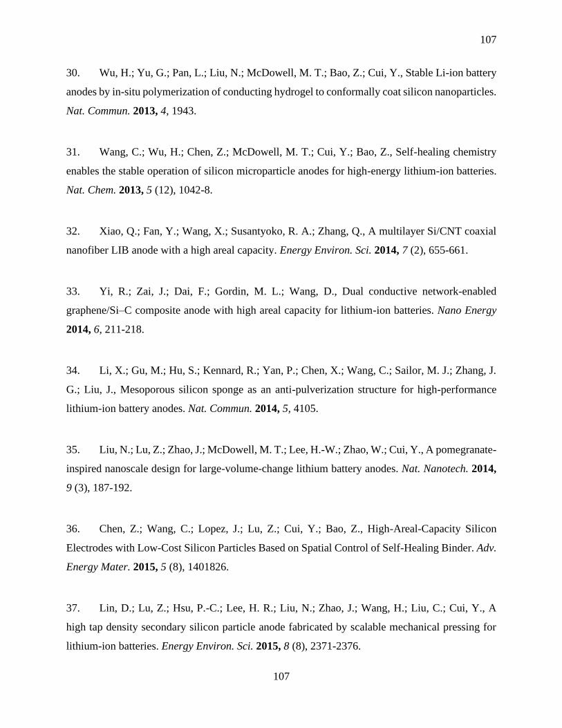
107
107
30. Wu, H.; Yu, G.; Pan, L.; Liu, N.; McDowell, M. T.; Bao, Z.; Cui, Y., Stable Li-ion battery
anodes by in-situ polymerization of conducting hydrogel to conformally coat silicon nanoparticles.
Nat. Commun. 2013, 4, 1943.
31. Wang, C.; Wu, H.; Chen, Z.; McDowell, M. T.; Cui, Y.; Bao, Z., Self-healing chemistry
enables the stable operation of silicon microparticle anodes for high-energy lithium-ion batteries.
Nat. Chem. 2013, 5 (12), 1042-8.
32. Xiao, Q.; Fan, Y.; Wang, X.; Susantyoko, R. A.; Zhang, Q., A multilayer Si/CNT coaxial
nanofiber LIB anode with a high areal capacity. Energy Environ. Sci. 2014, 7 (2), 655-661.
33. Yi, R.; Zai, J.; Dai, F.; Gordin, M. L.; Wang, D., Dual conductive network-enabled
graphene/Si–C composite anode with high areal capacity for lithium-ion batteries. Nano Energy
2014, 6, 211-218.
34. Li, X.; Gu, M.; Hu, S.; Kennard, R.; Yan, P.; Chen, X.; Wang, C.; Sailor, M. J.; Zhang, J.
G.; Liu, J., Mesoporous silicon sponge as an anti-pulverization structure for high-performance
lithium-ion battery anodes. Nat. Commun. 2014, 5, 4105.
35. Liu, N.; Lu, Z.; Zhao, J.; McDowell, M. T.; Lee, H.-W.; Zhao, W.; Cui, Y., A pomegranate-
inspired nanoscale design for large-volume-change lithium battery anodes. Nat. Nanotech. 2014,
9 (3), 187-192.
36. Chen, Z.; Wang, C.; Lopez, J.; Lu, Z.; Cui, Y.; Bao, Z., High-Areal-Capacity Silicon
Electrodes with Low-Cost Silicon Particles Based on Spatial Control of Self-Healing Binder. Adv.
Energy Mater. 2015, 5 (8), 1401826.
37. Lin, D.; Lu, Z.; Hsu, P.-C.; Lee, H. R.; Liu, N.; Zhao, J.; Wang, H.; Liu, C.; Cui, Y., A
high tap density secondary silicon particle anode fabricated by scalable mechanical pressing for
lithium-ion batteries. Energy Environ. Sci. 2015, 8 (8), 2371-2376.
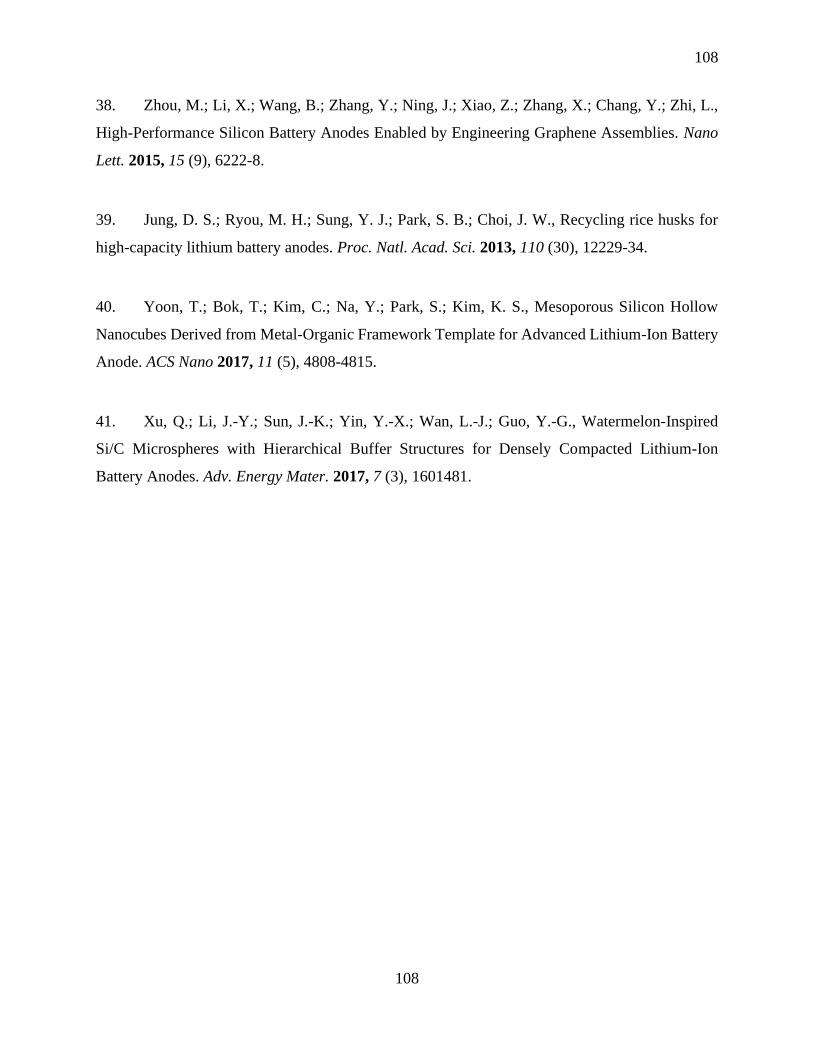
108
108
38. Zhou, M.; Li, X.; Wang, B.; Zhang, Y.; Ning, J.; Xiao, Z.; Zhang, X.; Chang, Y.; Zhi, L.,
High-Performance Silicon Battery Anodes Enabled by Engineering Graphene Assemblies. Nano
Lett. 2015, 15 (9), 6222-8.
39. Jung, D. S.; Ryou, M. H.; Sung, Y. J.; Park, S. B.; Choi, J. W., Recycling rice husks for
high-capacity lithium battery anodes. Proc. Natl. Acad. Sci. 2013, 110 (30), 12229-34.
40. Yoon, T.; Bok, T.; Kim, C.; Na, Y.; Park, S.; Kim, K. S., Mesoporous Silicon Hollow
Nanocubes Derived from Metal-Organic Framework Template for Advanced Lithium-Ion Battery
Anode. ACS Nano 2017, 11 (5), 4808-4815.
41. Xu, Q.; Li, J.-Y.; Sun, J.-K.; Yin, Y.-X.; Wan, L.-J.; Guo, Y.-G., Watermelon-Inspired
Si/C Microspheres with Hierarchical Buffer Structures for Densely Compacted Lithium-Ion
Battery Anodes. Adv. Energy Mater. 2017, 7 (3), 1601481.

109
109
Supporting Information
Figure S4.1 The Si-SA ink loaded in a 3cc syringe.
Figure S4.2 (a) Slurry-casted Si electrode under low areal loading (around 1.0 mg cm-2); (b)
Slurry-casted Si electrode under high areal loading (around 2.0 mg cm-2); (c) and (d) SEM
images of the low areal loading Si electrode.

110
110
Figure S4.3 Raman spectra of the 3D-VLMP Si electrodes (Inset: enlarged Raman peaks of
MWCNTs).
Figure S4.4 FTIR Spectra of the 3D-VLMP Si electrodes

111
111
Figure S4.5 CV curves of the 3D-VLMP Si electrode at a scanning rate of 0.2 mV S-1
Figure S4.6 Specific capacity vs. cycle at a current density of 1 Ag-1 for 60 cycles.
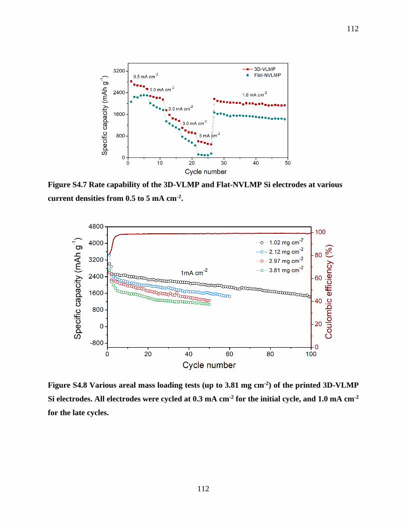
112
112
Figure S4.7 Rate capability of the 3D-VLMP and Flat-NVLMP Si electrodes at various
current densities from 0.5 to 5 mA cm-2.
Figure S4.8 Various areal mass loading tests (up to 3.81 mg cm-2) of the printed 3D-VLMP
Si electrodes. All electrodes were cycled at 0.3 mA cm-2 for the initial cycle, and 1.0 mA cm-2
for the late cycles.
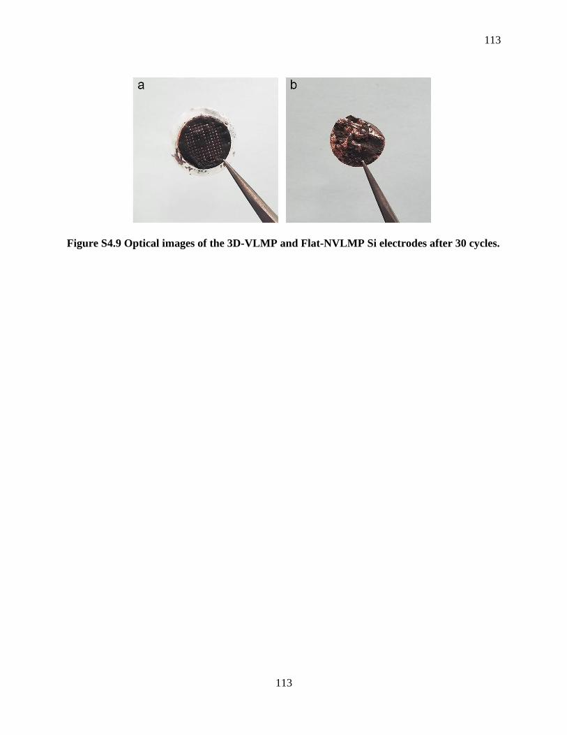
113
113
Figure S4.9 Optical images of the 3D-VLMP and Flat-NVLMP Si electrodes after 30 cycles.

114
114
Chapter 5
5 3D Printing of Shape-Versatile and Thin Solid Electrolyte for High-Performance Solid-
State Li-Metal Batteries
Solid-state Li-metal batteries have recently received considerable interests due to their high safety
and high energy density. However, it is of great challenge to fabricate a thin solid electrolyte
through a low-cost and facile approach. Herein, we successfully fabricate a LAGP thin film with
a thickness of around 70 µm via a low-cost and efficient extrusion-based 3D printing approach.
Compared with the conventional pressed thick solid-state electrolyte pellets, the printed thin solid-
state electrolyte can not only reduce the total weight of a cell but also shorten the Li+ transport
distance, which could increase the energy density and power density of a solid battery. Moreover,
various 3D LAGP architectures are constructed by using the same ink, which could broaden the
diversity of solid batteries with different size and shapes. This study thus demonstrates a low-cost
and facile strategy to fabricate shape-versatile and thin solid electrolytes for high-energy-density
solid-state energy storage systems.
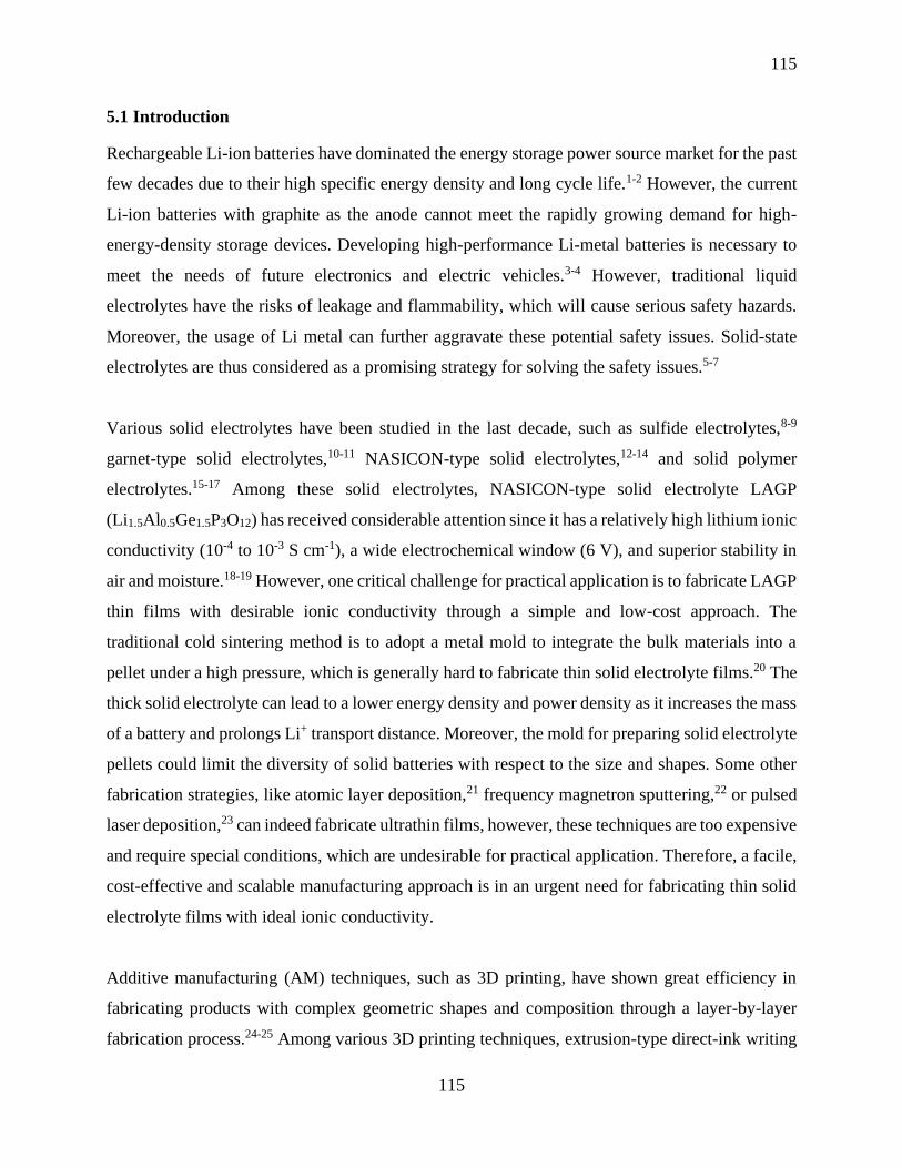
115
115
5.1 Introduction
Rechargeable Li-ion batteries have dominated the energy storage power source market for the past
few decades due to their high specific energy density and long cycle life.1-2 However, the current
Li-ion batteries with graphite as the anode cannot meet the rapidly growing demand for high-
energy-density storage devices. Developing high-performance Li-metal batteries is necessary to
meet the needs of future electronics and electric vehicles.3-4 However, traditional liquid
electrolytes have the risks of leakage and flammability, which will cause serious safety hazards.
Moreover, the usage of Li metal can further aggravate these potential safety issues. Solid-state
electrolytes are thus considered as a promising strategy for solving the safety issues.5-7
Various solid electrolytes have been studied in the last decade, such as sulfide electrolytes,8-9
garnet-type solid electrolytes,10-11 NASICON-type solid electrolytes,12-14 and solid polymer
electrolytes.15-17 Among these solid electrolytes, NASICON-type solid electrolyte LAGP
(Li1.5Al0.5Ge1.5P3O12) has received considerable attention since it has a relatively high lithium ionic
conductivity (10-4 to 10-3 S cm-1), a wide electrochemical window (6 V), and superior stability in
air and moisture.18-19 However, one critical challenge for practical application is to fabricate LAGP
thin films with desirable ionic conductivity through a simple and low-cost approach. The
traditional cold sintering method is to adopt a metal mold to integrate the bulk materials into a
pellet under a high pressure, which is generally hard to fabricate thin solid electrolyte films.20 The
thick solid electrolyte can lead to a lower energy density and power density as it increases the mass
of a battery and prolongs Li+ transport distance. Moreover, the mold for preparing solid electrolyte
pellets could limit the diversity of solid batteries with respect to the size and shapes. Some other
fabrication strategies, like atomic layer deposition,21 frequency magnetron sputtering,22 or pulsed
laser deposition,23 can indeed fabricate ultrathin films, however, these techniques are too expensive
and require special conditions, which are undesirable for practical application. Therefore, a facile,
cost-effective and scalable manufacturing approach is in an urgent need for fabricating thin solid
electrolyte films with ideal ionic conductivity.
Additive manufacturing (AM) techniques, such as 3D printing, have shown great efficiency in
fabricating products with complex geometric shapes and composition through a layer-by-layer
fabrication process.24-25 Among various 3D printing techniques, extrusion-type direct-ink writing
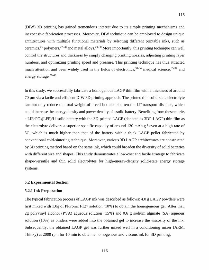
116
116
(DIW) 3D printing has gained tremendous interest due to its simple printing mechanisms and
inexpensive fabrication processes. Moreover, DIW technique can be employed to design unique
architectures with multiple functional materials by selecting different printable inks, such as
ceramics,26 polymers,27-28 and metal alloys.29-30 More importantly, this printing technique can well
control the structures and thickness by simply changing printing nozzles, adjusting printing layer
numbers, and optimizing printing speed and pressure. This printing technique has thus attracted
much attention and been widely used in the fields of electronics,31-34 medical science,35-37 and
energy storage.38-43
In this study, we successfully fabricate a homogenous LAGP thin film with a thickness of around
70 µm via a facile and efficient DIW 3D printing approach. The printed thin solid-state electrolyte
can not only reduce the total weight of a cell but also shorten the Li+ transport distance, which
could increase the energy density and power density of a solid battery. Benefiting from these merits,
a LiFePO4(LFP)/Li solid battery with the 3D-printed LAGP (denoted as 3DP-LAGP) thin film as
the electrolyte delivers a superior specific capacity of around 130 mAh g-1 even at a high rate of
5C, which is much higher than that of the battery with a thick LAGP pellet fabricated by
conventional cold-sintering technique. Moreover, various 3D LAGP architectures are constructed
by 3D printing method based on the same ink, which could broaden the diversity of solid batteries
with different size and shapes. This study demonstrates a low-cost and facile strategy to fabricate
shape-versatile and thin solid electrolytes for high-energy-density solid-state energy storage
systems.
5.2 Experimental Section
5.2.1 Ink Preparation
The typical fabrication process of LAGP ink was described as follows: 4.0 g LAGP powders were
first mixed with 1.0g of Pluronic F127 solution (10%) to obtain the homogeneous gel. After that,
2g polyvinyl alcohol (PVA) aqueous solution (15%) and 0.6 g sodium alginate (SA) aqueous
solution (10%) as binders were added into the obtained gel to increase the viscosity of the ink.
Subsequently, the obtained LAGP gel was further mixed well in a conditioning mixer (ARM,
Thinky) at 2000 rpm for 10 min to obtain a homogenous and viscous ink for 3D printing.
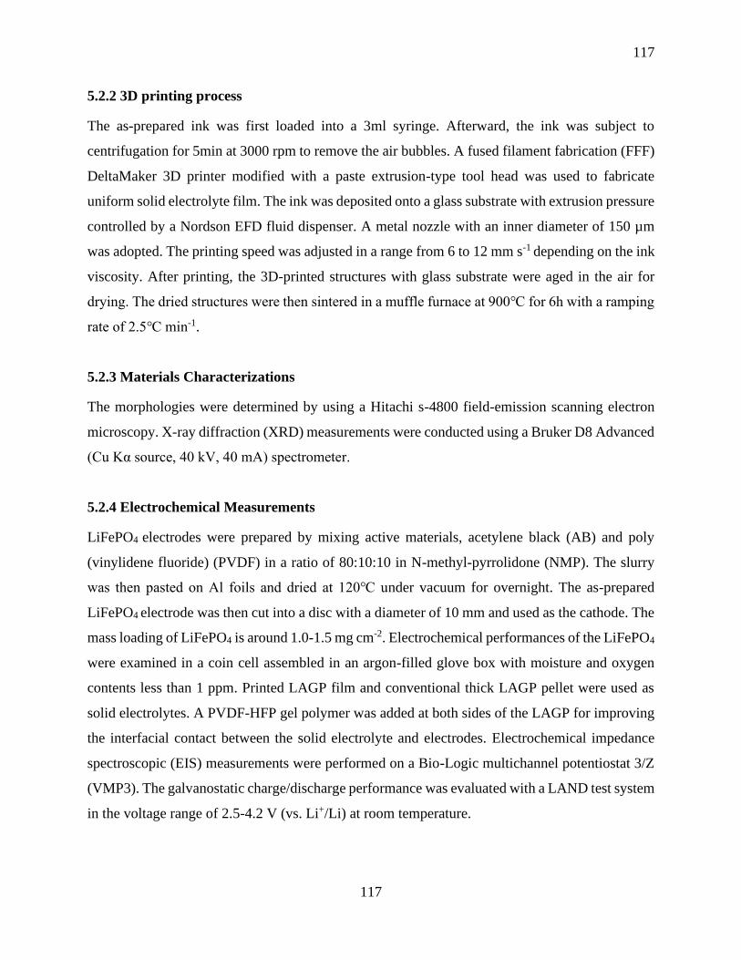
117
117
5.2.2 3D printing process
The as-prepared ink was first loaded into a 3ml syringe. Afterward, the ink was subject to
centrifugation for 5min at 3000 rpm to remove the air bubbles. A fused filament fabrication (FFF)
DeltaMaker 3D printer modified with a paste extrusion-type tool head was used to fabricate
uniform solid electrolyte film. The ink was deposited onto a glass substrate with extrusion pressure
controlled by a Nordson EFD fluid dispenser. A metal nozzle with an inner diameter of 150 µm
was adopted. The printing speed was adjusted in a range from 6 to 12 mm s-1 depending on the ink
viscosity. After printing, the 3D-printed structures with glass substrate were aged in the air for
drying. The dried structures were then sintered in a muffle furnace at 900 for 6h with a ramping
rate of 2.5 min-1.
5.2.3 Materials Characterizations
The morphologies were determined by using a Hitachi s-4800 field-emission scanning electron
microscopy. X-ray diffraction (XRD) measurements were conducted using a Bruker D8 Advanced
(Cu Kα source, 40 kV, 40 mA) spectrometer.
5.2.4 Electrochemical Measurements
LiFePO4 electrodes were prepared by mixing active materials, acetylene black (AB) and poly
(vinylidene fluoride) (PVDF) in a ratio of 80:10:10 in N-methyl-pyrrolidone (NMP). The slurry
was then pasted on Al foils and dried at 120 under vacuum for overnight. The as-prepared
LiFePO4 electrode was then cut into a disc with a diameter of 10 mm and used as the cathode. The
mass loading of LiFePO4 is around 1.0-1.5 mg cm-2. Electrochemical performances of the LiFePO4
were examined in a coin cell assembled in an argon-filled glove box with moisture and oxygen
contents less than 1 ppm. Printed LAGP film and conventional thick LAGP pellet were used as
solid electrolytes. A PVDF-HFP gel polymer was added at both sides of the LAGP for improving
the interfacial contact between the solid electrolyte and electrodes. Electrochemical impedance
spectroscopic (EIS) measurements were performed on a Bio-Logic multichannel potentiostat 3/Z
(VMP3). The galvanostatic charge/discharge performance was evaluated with a LAND test system
in the voltage range of 2.5-4.2 V (vs. Li+/Li) at room temperature.
118
118
5.3 Results and Discussion
5.3.1 Morphology and Structure Characterization
Figure 5.1 (a) Schematic illustration of 3D printing of LAGP solid electrolytes. (b) Schematic
illustration of the procedure for the synthesis of the thick LAGP pellet with a conventional
method. Optical images of 3D-printed LAGP with (c) unique letter shapes and (d) micro
lattice structures in different sizes. (e) Top-view SEM image of the microlattice structured
LAGP.
Figure 5.1a illustrates the LAGP solid electrolyte fabrication process by an extrusion-type 3D
printing method. This method is capable of fabricating LAGP solid electrolyte with controllable
thickness and shapes. In order to obtain fine printing LAGP structures, it is critically important to
prepare an ink with suitable viscosity and shear-thinning features. Specifically, a self-supported
printable LAGP ink was prepared by two steps: (1) LAGP powder was mixed with a small amount
of Pluronic F127 solution (10%) to obtain homogeneous gel, and (2) Polyvinyl alcohol (PVA) and
sodium alginate (SA) aqueous solution as binders were added into the obtained gel to increase the
viscosity of the ink. The mixture was then transferred into a Think mixer to get desirable printing
ink. Subsequently, the LAGP ink was loaded into a syringe (Figure S5.1) and extruded layer-by-

119
119
layer through a metal nozzle onto a glass slide controlled by a pre-designed program. The printed
structures were dried at room temperature and then sintered in a muffle furnace to remove the
binders and obtain fine LAGP structures. For obtaining a thin LAGP film, a single-layer dense
LAGP film was printed and sintered, the printed height was adjusted to 150 µm. Figure 5.1b
shows the fabrication process of a thick LAGP pellet (denoted as Con-LAGP) with a conventional
method, where the thickness and size of the LAGP are greatly limited by the mold (Figure S5.2)
used for fabricating pellets. Compared with the printed LAGP, the conventional pressed LAGP
pellet is too thick, which will undoubtedly increase the total weight of a battery and reduce the
energy density of the solid battery. Interestingly, LAGP with various patterns, such as unique
letters and microlattice structures with different sizes as shown in Figure S5.3 and S5.4, can be
printed based on the prepared ink. Figure 5.1c and 5.1d display that the printed various patterned
LAGP can maintain the shape very well with fine and smooth surface after the thermal annealing
process (Figure 5.1e). This thus demonstrates that 3D printing has potential in fabricating 3D solid
batteries with controllable sizes and shapes.

120
120
Figure 5.2. Digital photos of (a) the Con-LAGP thick pellet and (d) the 3DP-LAGP thin film.
(b-c) Cross-sectional SEM images of (b-c) the Con-LAGP and (e-f) the 3DP-LAGP at
different magnifications, respectively. (g) XRD patterns of 3DP-LAGP before and after
thermal annealing. (h) EIS plots of the 3DP-LAGP at different temperatures of 25-75. (i)
Conductivity vs. 1000/T of 3DP-LAGP electrolyte.
Figure 5.2a and 5.2d show the digital photos of the Con-LAGP thick electrolyte and 3DP-LAGP
thin electrolyte after thermal annealing, respectively. Both LAGP films display a smooth surface
and a diameter of around 12 mm, which is suitable for acting as electrolytes in the coin-cell. SEM
images were applied to figure out the exact thickness and microstructures of the two LAGP films.
Figure 5.2b presents the cross-sectional SEM image of the Con-LAGP with a thickness of
approximately 0.95 mm. Figure 5.2c is a higher magnification SEM image of the cross-section,
which reveals that most of the particles with the size of around 0.5-1.0 µm are closely connected,
although a few voids are found between the grain boundaries of the LAGP. On the other hand, the
cross-sectional SEM image of the 3DP-LAGP film is displayed in Figure 5.2e, it can be clearly
observed that the 3DP-LAGP film presents a thickness of around 70 µm, which is much thinner
than that of the Con-LAGP pellet. Figure 5.2f and Figure S5.5 show the enlarged cross-sectional
SEM images of the 3DP-LAGP. It can be found that all the particles are uniformly distributed and
closely connected, presenting a smooth surface without any impurities. The microstructure of the
3DP-LAGP film displays similar features with that of the Con-LAGP thick pellet, suggesting a
desirable ionic conductivity of the printed thin LAGP film.
X-ray diffraction (XRD) was conducted to determine the phase of the printed LAGP before and
after thermal annealing. As shown in Figure 5.2g, there were no impurity diffraction peaks can be
found in both samples and the XRD patterns of both samples can be well indexed to pure LAGP
phase with NASICON structure, suggesting that the ink preparation and thermal treatment
processes did not affect the phase and structure of the LAGP. The ionic conductivity of the
obtained LAGP was investigated using electrochemical impedance spectroscopy (EIS). Figure
5.2h shows the EIS profiles of LAGP at various temperature, it can be found that the ionic
conductivity of LAGP is 1.67 × 10⁻⁴ S cm-1 at the room temperature. Figure 5.2i presents the
121
121
temperature dependence of the ionic conductivity of the LAGP, which displayed an Arrhenius
behavior according to the Arrhenius equation σ (T) = Aexp(-Ea/kBT), where σ is the ionic
conductivity, T is the temperature in Kelvin, kB is the Boltzmann constant, A is the pre-exponential
factor, and Ea is the activation energy for Li+ hopping between two adjacent sites. The activation
energy of the LAGP was determined to be 32.15 kJ mol-1, which is comparable with other reported
values.44
5.3.2 Electrochemical Characterization
Figure 5.3 Electrochemical performance characterization of the printed LAGP thin film. (a)
EIS of the LiFePO4/Li batteries with 3DP-LAGP and Con-LAGP as the electrolytes,
respectively (b) Rate capabilities of 3DP-LAGP based solid Li-battery and Con-LAGP based
solid Li-battery at a current density range of 0.1C to 5C. Typical charge/discharge voltage
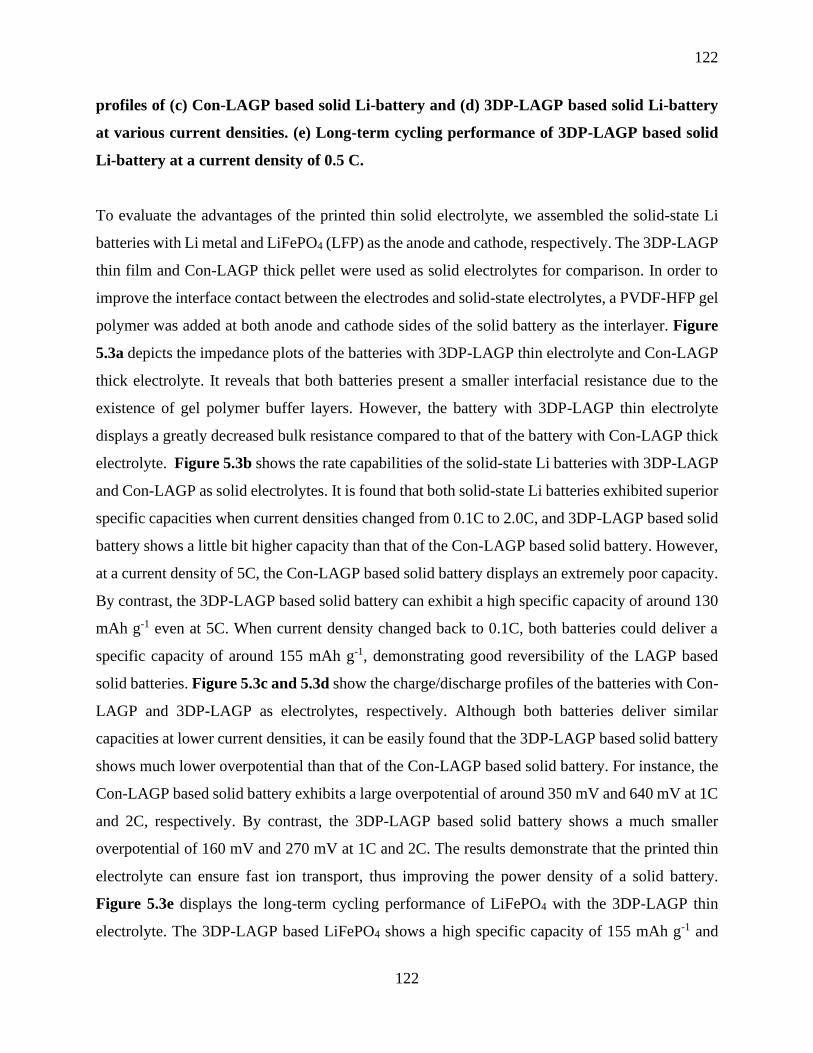
122
122
profiles of (c) Con-LAGP based solid Li-battery and (d) 3DP-LAGP based solid Li-battery
at various current densities. (e) Long-term cycling performance of 3DP-LAGP based solid
Li-battery at a current density of 0.5 C.
To evaluate the advantages of the printed thin solid electrolyte, we assembled the solid-state Li
batteries with Li metal and LiFePO4 (LFP) as the anode and cathode, respectively. The 3DP-LAGP
thin film and Con-LAGP thick pellet were used as solid electrolytes for comparison. In order to
improve the interface contact between the electrodes and solid-state electrolytes, a PVDF-HFP gel
polymer was added at both anode and cathode sides of the solid battery as the interlayer. Figure
5.3a depicts the impedance plots of the batteries with 3DP-LAGP thin electrolyte and Con-LAGP
thick electrolyte. It reveals that both batteries present a smaller interfacial resistance due to the
existence of gel polymer buffer layers. However, the battery with 3DP-LAGP thin electrolyte
displays a greatly decreased bulk resistance compared to that of the battery with Con-LAGP thick
electrolyte. Figure 5.3b shows the rate capabilities of the solid-state Li batteries with 3DP-LAGP
and Con-LAGP as solid electrolytes. It is found that both solid-state Li batteries exhibited superior
specific capacities when current densities changed from 0.1C to 2.0C, and 3DP-LAGP based solid
battery shows a little bit higher capacity than that of the Con-LAGP based solid battery. However,
at a current density of 5C, the Con-LAGP based solid battery displays an extremely poor capacity.
By contrast, the 3DP-LAGP based solid battery can exhibit a high specific capacity of around 130
mAh g-1 even at 5C. When current density changed back to 0.1C, both batteries could deliver a
specific capacity of around 155 mAh g-1, demonstrating good reversibility of the LAGP based
solid batteries. Figure 5.3c and 5.3d show the charge/discharge profiles of the batteries with Con-
LAGP and 3DP-LAGP as electrolytes, respectively. Although both batteries deliver similar
capacities at lower current densities, it can be easily found that the 3DP-LAGP based solid battery
shows much lower overpotential than that of the Con-LAGP based solid battery. For instance, the
Con-LAGP based solid battery exhibits a large overpotential of around 350 mV and 640 mV at 1C
and 2C, respectively. By contrast, the 3DP-LAGP based solid battery shows a much smaller
overpotential of 160 mV and 270 mV at 1C and 2C. The results demonstrate that the printed thin
electrolyte can ensure fast ion transport, thus improving the power density of a solid battery.
Figure 5.3e displays the long-term cycling performance of LiFePO4 with the 3DP-LAGP thin
electrolyte. The 3DP-LAGP based LiFePO4 shows a high specific capacity of 155 mAh g-1 and

123
123
remains as high as 146 mAh g-1 even over 850 cycles, which gives an extremely stable cycling
performance with a lower capacity decay rate of 0.0068% per cycle. However, the LiFePO4 with
the pure gel polymer electrolyte undergoes a fast capacity decay and only shows a capacity of
around 72 mAh g-1 after 850 cycles with a capacity retention of 46% as presented in Figure S5.6.
By contrast, the Con-LAGP based LiFePO4 delivers high cycling stability (Figure S5.7), which is
similar to the cycling performance of the 3DP-LAGP based LiFePO4. The excellent cycling
performance suggests that the LAGP solid electrolyte can suppress the lithium dendrite growth,
thereby leading to a highly safe Li-metal battery.
Figure 5.4 Schematic illustration of Li+ transport kinetics in solid-state Li batteries with (a)
3D-printed thin LAGP and (b) conventional thick LAGP as solid electrolytes.
The superior rate performance of LiFePO4/Li batteries with 3DP-LAGP as the solid electrolyte
can be attributed to the reduced Li+ transport path as illustrated in Figure 5.4. In a solid-state Li
battery, the Li+ will transport from the cathode to the Li anode upon cycling, where the Li+
transport kinetic is mainly determined by the solid-state electrolyte between the anode and the
cathode. To this end, the 3DP-LAGP thin film with desirable ionic conductivity could greatly
shorten the transport distance, thus leading to a fast Li+ transport (Figure 5.4a). By contrast, the
Con-LAGP thick pellet based solid batteries exhibit a prolonged Li+ transport path (Figure 5.4b),
resulting in poor rate capabilities, especially at a high current density. Therefore, the printed thin
electrolyte could ensure an improved energy density and power density of the solid battery due to
the reduced total weight of a cell and fast Li+ transport upon cycling. This work is thus expected
124
124
to open a new avenue to design high-performance solid batteries with high energy density and
power density through 3D printing technologies.
5.4 Conclusion
We have developed a low-cost aqueous-based printable ink for fabricating uniform LAGP thin
films via an advanced extrusion-type 3D printing approach. Compared with the conventional
pressed thick LAGP pellets, the printed thin LAGP can not only reduce the total weight of a cell
but also shorten the Li+ transport distance, which could increase the energy density and power
density of a solid battery. This method offers the flexibility of fabricating thin solid-state
electrolytes with controllable thickness in a low-cost and efficient way. In addition, various
patterned LAGP architectures are easily fabricated, broadening the diversity of solid batteries with
various size and shapes. This work thus would shed light on fabricating desirable solid-state
electrolytes for next-generation high energy density solid-state batteries.
Acknowledgements
The work was supported by Natural Science Foundation of China (NSFC) (Grant U1432249), the
National Key R&D Program of China (Grant 2017YFA0205002), and the Priority Academic
Program Development (PAPD) of Jiangsu Higher Education Institutions. This is also a project
supported by Jiangsu Key Laboratory for Carbon-Based Functional Materials and Devices and
Collaborative Innovation Center of Suzhou Nano Science & Technology. This work was also
supported by the Natural Science and Engineering Research Council of Canada (NSERC), the
Canada Research Chair Program (CRC), the Canada Foundation for Innovation (CFI), and the
University of Western Ontario (UWO).
5.5 References
1. Tarascon, J. M.; Armand, M., Issues and challenges facing rechargeable lithium batteries.
Nature 2001, 414, 359.
2. Gao, X.; Wang, J.; Zhang, D.; Adair, K.; Feng, K.; Sun, N.; Zheng, H.; Shao, H.; Zhong,
J.; Ma, Y.; Sun, X.; Sun, X., Carbon coated bimetallic sulfide nanodots/carbon nanorod

125
125
heterostructure enabling long-life lithium-ion batteries. J. Mater. Chem. A 2017, 5 (48), 25625-
25631.
3. Lin, D.; Liu, Y.; Cui, Y., Reviving the lithium metal anode for high-energy batteries. Nat.
Nanotech. 2017, 12 (3), 194-206.
4. Zhang, R.; Li, N.-W.; Cheng, X.-B.; Yin, Y.-X.; Zhang, Q.; Guo, Y.-G., Advanced
Micro/Nanostructures for Lithium Metal Anodes. Adv. Sci. 2017, 4 (3), 1600445-n/a.
5. Manthiram, A.; Yu, X.; Wang, S., Lithium battery chemistries enabled by solid-state
electrolytes. Nat. Rev. Mater. 2017, 2, 16103.
6. Zheng, F.; Kotobuki, M.; Song, S.; Lai, M. O.; Lu, L., Review on solid electrolytes for all-
solid-state lithium-ion batteries. J. Power Sources 2018, 389, 198-213.
7. Gao, Z.; Sun, H.; Fu, L.; Ye, F.; Zhang, Y.; Luo, W.; Huang, Y., Promises, Challenges,
and Recent Progress of Inorganic Solid-State Electrolytes for All-Solid-State Lithium Batteries.
Adv.Mater. 2018, 30 (17), e1705702.
8. Lau, J.; DeBlock, R. H.; Butts, D. M.; Ashby, D. S.; Choi, C. S.; Dunn, B. S., Sulfide Solid
Electrolytes for Lithium Battery Applications. Adv. Energy Mater. 2018, 8 (27), 1800933.
9. Wang, C.; Adair, K. R.; Liang, J.; Li, X.; Sun, Y.; Li, X.; Wang, J.; Sun, Q.; Zhao, F.; Lin,
X.; Li, R.; Huang, H.; Zhang, L.; Yang, R.; Lu, S.; Sun, X., Solid‐State Plastic Crystal Electrolytes:
Effective Protection Interlayers for Sulfide‐Based All‐Solid‐State Lithium Metal Batteries. Adv.
Funct. Mater. 2019, 1900392.
10. Bae, J.; Li, Y.; Zhao, F.; Zhou, X.; Ding, Y.; Yu, G., Designing 3D nanostructured garnet
frameworks for enhancing ionic conductivity and flexibility in composite polymer electrolytes for
lithium batteries. Energy Storage Mater. 2018, 15, 46-52.
126
126
11. Wang, D.; Sun, Q.; Luo, J.; Liang, J.; Sun, Y.; Li, R.; Adair, K.; Zhang, L.; Yang, R.; Lu,
S.; Huang, H.; Sun, X., Mitigating the Interfacial Degradation in Cathodes for High-Performance
Oxide-Based Solid-State Lithium Batteries. ACS Appl. Mater. Interfaces 2019, 11 (5), 4954-4961.
12. Wang, C.; Sun, Q.; Liu, Y.; Zhao, Y.; Li, X.; Lin, X.; Banis, M. N.; Li, M.; Li, W.; Adair,
K. R.; Wang, D.; Liang, J.; Li, R.; Zhang, L.; Yang, R.; Lu, S.; Sun, X., Boosting the performance
of lithium batteries with solid-liquid hybrid electrolytes: Interfacial properties and effects of liquid
electrolytes. Nano Energy 2018, 48, 35-43.
13. Liu, Y.; Li, C.; Li, B.; Song, H.; Cheng, Z.; Chen, M.; He, P.; Zhou, H., Germanium Thin
Film Protected Lithium Aluminum Germanium Phosphate for Solid-State Li Batteries. Adv.
Energy Mater. 2018, 8 (16), 1702374.
14. Liang, J.; Sun, Q.; Zhao, Y.; Sun, Y.; Wang, C.; Li, W.; Li, M.; Wang, D.; Li, X.; Liu, Y.;
Adair, K.; Li, R.; Zhang, L.; Yang, R.; Lu, S.; Huang, H.; Sun, X., Stabilization of all-solid-state
Li–S batteries with a polymer–ceramic sandwich electrolyte by atomic layer deposition. J. Mater.
Chem. A 2018, 6 (46), 23712-23719.
15. Sheng, O.; Jin, C.; Luo, J.; Yuan, H.; Huang, H.; Gan, Y.; Zhang, J.; Xia, Y.; Liang, C.;
Zhang, W.; Tao, X., Mg2B2O5 Nanowire Enabled Multifunctional Solid-State Electrolytes with
High Ionic Conductivity, Excellent Mechanical Properties, and Flame-Retardant Performance.
Nano Lett. 2018, 18 (5), 3104-3112.
16. Zhai, H.; Xu, P.; Ning, M.; Cheng, Q.; Mandal, J.; Yang, Y., A Flexible Solid Composite
Electrolyte with Vertically Aligned and Connected Ion-Conducting Nanoparticles for Lithium
Batteries. Nano Lett. 2017, 17 (5), 3182-3187.
17. Zhang, X.; Xie, J.; Shi, F.; Lin, D.; Liu, Y.; Liu, W.; Pei, A.; Gong, Y.; Wang, H.; Liu, K.;
Xiang, Y.; Cui, Y., Vertically Aligned and Continuous Nanoscale Ceramic–Polymer Interfaces in
127
127
Composite Solid Polymer Electrolytes for Enhanced Ionic Conductivity. Nano Lett. 2018, 18 (6),
3829-3838.
18. Fu, J., Fast Li+ ion couducting glass-ceramics in the system Li2O-Al2O3-GeO2-P2O5. Solid
State Ionics 1997, 104, 191-194.
19. Wang, S.; Wang, J.; Liu, J.; Song, H.; Liu, Y.; Wang, P.; He, P.; Xu, J.; Zhou, H., Ultra-
fine surface solid-state electrolytes for long cycle life all-solid-state lithium–air batteries. J. Mater.
Chem. A 2018, 6 (43), 21248-21254.
20. Liu, Y.; Sun, Q.; Wang, D.; Adair, K.; Liang, J.; Sun, X., Development of the cold sintering
process and its application in solid-state lithium batteries. J. Power Sources 2018, 393, 193-203.
21. Wang, B.; Liu, J.; Norouzi Banis, M.; Sun, Q.; Zhao, Y.; Li, R.; Sham, T. K.; Sun, X.,
Atomic Layer Deposited Lithium Silicates as Solid-State Electrolytes for All-Solid-State Batteries.
ACS Appl. Mater. Interfaces 2017, 9 (37), 31786-31793.
22. Choi, C. H.; Cho, W. I.; Cho, B. W.; Kim, H. S.; Yoon, Y. S.; Tak, Y. S., Radio-Frequency
Magnetron Sputtering Power Effect on the Ionic Conductivities of Lipon Films. Electrochem.
Solid-State Lett. 2002, 5 (1), A14.
23. Saccoccio, M.; Yu, J.; Lu, Z.; Kwok, S. C. T.; Wang, J.; Yeung, K. K.; Yuen, M. M. F.;
Ciucci, F., Low temperature pulsed laser deposition of garnet Li 6.4 La 3 Zr 1.4 Ta 0.6 O 12 films as
all solid-state lithium battery electrolytes. J. Power Sources 2017, 365, 43-52.
24. Ruiz-Morales, J. C.; Tarancón, A.; Canales-Vázquez, J.; Méndez-Ramos, J.; Hernández-
Afonso, L.; Acosta-Mora, P.; Marín Rueda, J. R.; Fernández-González, R., Three dimensional
printing of components and functional devices for energy and environmental applications. Energy
Environ. Sci. 2017.
128
128
25. Tian, X.; Jin, J.; Yuan, S.; Chua, C. K.; Tor, S. B.; Zhou, K., Emerging 3D-Printed
Electrochemical Energy Storage Devices: A Critical Review. Adv. Energy Mater. 2017, 7 (17),
1700127.
26. Nguyen, D. T.; Meyers, C.; Yee, T. D.; Dudukovic, N. A.; Destino, J. F.; Zhu, C.; Duoss,
E. B.; Baumann, T. F.; Suratwala, T.; Smay, J. E.; Dylla-Spears, R., 3D-Printed Transparent Glass.
Adv. Mater. 2017, 29 (26), 1701181-n/a.
27. Dizon, J. R. C.; Espera, A. H.; Chen, Q.; Advincula, R. C., Mechanical Characterization of
3D-Printed Polymers. Addit. Manuf. 2018, 20, 44-67.
28. Guo, S. Z.; Qiu, K.; Meng, F.; Park, S. H.; McAlpine, M. C., 3D Printed Stretchable Tactile
Sensors. Adv. Mater. 2017, 29 (27).
29. Jakus, A. E.; Taylor, S. L.; Geisendorfer, N. R.; Dunand, D. C.; Shah, R. N., Metallic
Architectures from 3D-Printed Powder-Based Liquid Inks. Adv. Funct. Mater. 2015, 25 (45),
6985-6995.
30. Yan, P.; Brown, E.; Su, Q.; Li, J.; Wang, J.; Xu, C.; Zhou, C.; Lin, D., 3D Printing
Hierarchical Silver Nanowire Aerogel with Highly Compressive Resilience and Tensile
Elongation through Tunable Poisson's Ratio. Small 2017, 1701756-n/a.
31. Mohammed, M. G.; Kramer, R., All-Printed Flexible and Stretchable Electronics.
Adv.Mater. 2017, 29 (19), 1604965.
32. Shin, S. R.; Farzad, R.; Tamayol, A.; Manoharan, V.; Mostafalu, P.; Zhang, Y. S.; Akbari,
M.; Jung, S. M.; Kim, D.; Comotto, M.; Annabi, N.; Al-Hazmi, F. E.; Dokmeci, M. R.;
Khademhosseini, A., A Bioactive Carbon Nanotube-Based Ink for Printing 2D and 3D Flexible
Electronics. Adv. Mater. 2016, 28 (17), 3280-3289.

129
129
33. Valentine, A. D.; Busbee, T. A.; Boley, J. W.; Raney, J. R.; Chortos, A.; Kotikian, A.;
Berrigan, J. D.; Durstock, M. F.; Lewis, J. A., Hybrid 3D Printing of Soft Electronics. Adv. Mater.
2017, 29 (40), 1703817.
34. Yang, H.; Leow, W. R.; Chen, X., 3D Printing of Flexible Electronic Devices. Small
Methods 2018, 2 (1), 1700259.
35. Forget, A.; Blaeser, A.; Miessmer, F.; Kopf, M.; Campos, D. F. D.; Voelcker, N. H.;
Blencowe, A.; Fischer, H.; Shastri, V. P., Mechanically Tunable Bioink for 3D Bioprinting of
Human Cells. Adv. Healthc. Mater. 2017, 6 (20).
36. Gao, F.; Xu, Z.; Liang, Q.; Liu, B.; Li, H.; Wu, Y.; Zhang, Y.; Lin, Z.; Wu, M.; Ruan, C.;
Liu, W., Direct 3D Printing of High Strength Biohybrid Gradient Hydrogel Scaffolds for Efficient
Repair of Osteochondral Defect. Adv. Funct. Mater. 2018, 1706644-n/a.
37. Qian, F.; Zhu, C.; Knipe, J. M.; Ruelas, S.; Stolaroff, J. K.; DeOtte, J. R.; Duoss, E. B.;
Spadaccini, C. M.; Henard, C. A.; Guarnieri, M. T.; Baker, S. E., Direct Writing of Tunable Living
Inks for Bioprocess Intensification. Nano Lett. 2019.
38. Díaz-Marta, A. S.; Tubío, C. R.; Carbajales, C.; Fernández, C.; Escalante, L.; Sotelo, E.;
Guitián, F.; Barrio, V. L.; Gil, A.; Coelho, A., Three-Dimensional Printing in Catalysis:
Combining 3D Heterogeneous Copper and Palladium Catalysts for Multicatalytic Multicomponent
Reactions. ACS Catal. 2017, 8 (1), 392-404.
39. Gao, X.; Sun, Q.; Yang, X.; Liang, J.; Koo, A.; Li, W.; Liang, J.; Wang, J.; Li, R.; Holness,
F. B.; Price, A. D.; Yang, S.; Sham, T.-K.; Sun, X., Toward a Remarkable Li-S battery via 3D
Printing. Nano Energy 2019, 56, 595-603.
40. Lacey, S. D.; Kirsch, D. J.; Li, Y.; Morgenstern, J. T.; Zarket, B. C.; Yao, Y.; Dai, J.; Garcia,
L. Q.; Liu, B.; Gao, T.; Xu, S.; Raghavan, S. R.; Connell, J. W.; Lin, Y.; Hu, L., Extrusion-Based

130
130
3D Printing of Hierarchically Porous Advanced Battery Electrodes. Adv. Mater. 2016, 1705651-
n/a.
41. Sun, K.; Wei, T. S.; Ahn, B. Y.; Seo, J. Y.; Dillon, S. J.; Lewis, J. A., 3D printing of
interdigitated Li-ion microbattery architectures. Adv. Mater. 2013, 25 (33), 4539-43.
42. Wang, J.; Sun, Q.; Gao, X.; Wang, C.; Li, W.; Holness, F. B.; Zheng, M.; Li, R.; Price, A.
D.; Sun, X.; Sham, T. K.; Sun, X., Toward High Areal Energy and Power Density Electrode for
Li-Ion Batteries via Optimized 3D Printing Approach. ACS Appl. Mater. Interfaces 2018, 10 (46),
39794-39801.
43. Yao, B.; Chandrasekaran, S.; Zhang, J.; Xiao, W.; Qian, F.; Zhu, C.; Duoss, E. B.;
Spadaccini, C. M.; Worsley, M. A.; Li, Y., Efficient 3D Printed Pseudocapacitive Electrodes with
Ultrahigh MnO2 Loading. Joule 2019, 3 (2), 459-470.
44. Wang, C.; Zhao, Y.; Sun, Q.; Li, X.; Liu, Y.; Liang, J.; Li, X.; Lin, X.; Li, R.; Adair, K. R.;
Zhang, L.; Yang, R.; Lu, S.; Sun, X., Stabilizing interface between Li10SnP2S12 and Li metal by
molecular layer deposition. Nano Energy 2018, 53, 168-174.
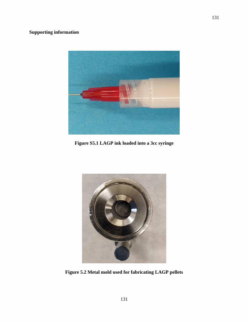
131
131
Supporting information
Figure S5.1 LAGP ink loaded into a 3cc syringe
Figure 5.2 Metal mold used for fabricating LAGP pellets

132
132
Figure S5.3 3D-printed LAGP with unique “UWO” letters before annealing
Figure S5.4 3D-printed LAGP micro-lattices with different size before annealing
Figure S5.5 Enlarged cross-sectional SEM image of the 3DP-LAGP film.
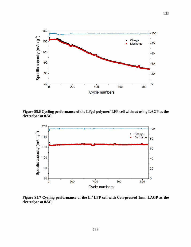
133
133
Figure S5.6 Cycling performance of the Li/gel polymer/ LFP cell without using LAGP as the
electrolyte at 0.5C.
Figure S5.7 Cycling performance of the Li/ LFP cell with Con-pressed 1mm LAGP as the
electrolyte at 0.5C.

134
134
Chapter 6
6 3D Printing of High-Performance Sodium Metal Batteries
Extrusion-based 3D printing is becoming a promising approach to construct high-performance
energy storage devices with various shapes and form factors. However, 3D printing technique has
not been applied to fabricate high-energy-density sodium metal batteries (SMBs) as great
challenge lies at the printing of highly reactive sodium metal. Here, for the first time, an extrusion-
based 3D printing approach was developed to construct a high-performance SMB consisting of a
printed Na@rGO/CNT anode and a printed O3-NaCu1/9Ni2/9Fe3/9Mn3/9O2 (denoted as NCNFM)
cathode. The 3D-printed Na@rGO/CNT anode possesses multiple porosities, which could provide
abundant active reaction sites and enable fast Na+ transport. Moreover, the resultant 3D
structured Na@rGO/CNT can effectively suppress the Na dendrite growth by decreasing the local
current density and releasing the huge volume change of Na during cycling. On the other hand,
the 3D-printed micro-structured NCNFM cathode composed of interconnected CNTs and porous
polymer framework can enable fast electron and ion transport as well as facilitated electrolyte
penetration within the whole electrode. This work offers a promising approach to construct high-
energy-density SMBs, which can also be extended to the developing of next-generation Na-S and
Na-O2 batteries.
135
135
6.1 Introduction
3D printing, also known as additive manufacturing (AM), has recently attracted tremendous
interest in myriad different fields from medical science1-2 to electronics,3-4 robotics,5 and energy
storage and conversion devices.6-8 This technique is considered to be an ideal manufacturing
method since it can create complex 3D architectures accurately and efficiency and significantly
reduce the manufacturing cost by eliminating the materials wastage. Up to now, various 3D
printing techniques have been developed and employed in industry and academic for fabricating
3D structures.9-11 Among them, extrusion-type 3D printing, known as robocasting or direct ink
writing, is the most popular and used in a broad range of applications due to its simple printing
mechanisms and inexpensive fabrication processes. Moreover, extrusion-type 3D printing can be
applied to a wide range of materials including polymers,12 ceramics,13 metal alloys,14 and
electronically functional materials,15-16 which greatly broadens its applicability in a wide range of
fields.
In recent years, extrusion-type 3D printing technique has been employed to construct various 3D
structured electrodes or other components with controlled shapes, and periodic or aligned pores
for energy storage systems. For instance, extrusion-based 3D printing has been applied to fabricate
advanced electrodes for Li-ion batteries,17-19 Li-O2/CO2 batteries,20-22 Li-S batteries,23-25 and
supercapacitors.26-27 Apart from the electrode fabrication, 3D printing has also found applications
in the fabrication of high-energy-density micro-batteries, which provides new possibilities for
constructing customized energy storage devices. Lewis and co-workers first reported the
fabrication of a 3D interdigitated Li-ion micro-battery using the 3D printing technique with the
printed LiFePO4 (LFP) and Li4Ti5O12 (LTO) as the cathode and anode, respectively.28 Following
this work, Hu et at. successfully printed a micro-battery with enhanced performance based on
highly concentrated graphene oxide composite inks.29 Very recently, 3D printing technique has
been employed to fabricate high-performance Li metal batteries (LMBs) with a 3D-printed Li
anode and a 3D-printed LFP cathode by using cellulose nanofiber (CNF)-based inks,30 which
significantly improved the energy density due to the utilization of the printed Li metal anode. To
the best of our knowledge, extrusion-based 3D printing technology has not been applied to
fabricate sodium metal batteries (SMBs). SMBs are attracting much research interest due to the
high capacity, low cost, and abundant natural source of Na metal.31-32 However, Na metal is highly
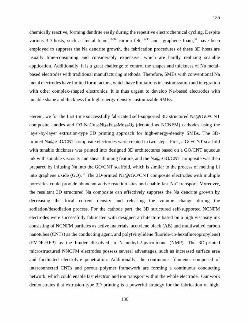
136
136
chemically reactive, forming dendrite easily during the repetitive electrochemical cycling. Despite
various 3D hosts, such as metal foam,33-34 carbon felt,35-36 and graphene foam,37 have been
employed to suppress the Na dendrite growth, the fabrication procedures of these 3D hosts are
usually time-consuming and considerably expensive, which are hardly realizing scalable
application. Additionally, it is a great challenge to control the shapes and thickness of Na metal-
based electrodes with traditional manufacturing methods. Therefore, SMBs with conventional Na
metal electrodes have limited form factors, which have limitations in customization and integration
with other complex-shaped electronics. It is thus urgent to develop Na-based electrodes with
tunable shape and thickness for high-energy-density customizable SMBs.
Herein, we for the first time successfully fabricated self-supported 3D structured Na@rGO/CNT
composite anodes and O3-NaCu1/9Ni2/9Fe3/9Mn3/9O2 (denoted as NCNFM) cathodes using the
layer-by-layer extrusion-type 3D printing approach for high-energy-density SMBs. The 3D-
printed Na@rGO/CNT composite electrodes were created in two steps. First, a GO/CNT scaffold
with tunable thickness was printed into designed 3D architectures based on a GO/CNT aqueous
ink with suitable viscosity and shear-thinning feature, and the Na@rGO/CNT composite was then
prepared by infusing Na into the GO/CNT scaffold, which is similar to the process of melting Li
into graphene oxide (GO).38 The 3D-printed Na@rGO/CNT composite electrodes with multiple
porosities could provide abundant active reaction sites and enable fast Na+ transport. Moreover,
the resultant 3D structured Na composite can effectively suppress the Na dendrite growth by
decreasing the local current density and releasing the volume change during the
sodiation/desodiation process. For the cathode part, the 3D structured self-supported NCNFM
electrodes were successfully fabricated with designed architecture based on a high viscosity ink
consisting of NCNFM particles as active materials, acetylene black (AB) and multiwalled carbon
nanotubes (CNTs) as the conducting agent, and poly(vinylidene fluoride-co-hexafluoropropylene)
(PVDF-HFP) as the binder dissolved in N-methyl-2-pyrrolidone (NMP). The 3D-printed
microstructured NNCFM electrodes possess several advantages, such as increased surface area
and facilitated electrolyte penetration. Additionally, the continuous filaments composed of
interconnected CNTs and porous polymer framework are forming a continuous conducting
network, which could enable fast electron and ion transport within the whole electrode. Our work
demonstrates that extrusion-type 3D printing is a powerful strategy for the fabrication of high-

137
137
performance SMBs. This work will also shed light on the fabrication of advanced energy storage
devices with customized designs.
6.2 Experimental Section
6.2.1 Material synthesis
The O3-NCNFM was synthesized by a traditional solid-state reaction. Typically, a stoichiometric
mixture of Na2CO3 (99%, Sigma-Aldrich), CuO (99%, Sigma-Aldrich), NiO (99%, Sigma-
Aldrich), Fe2O3 (99%, Sigma-Aldrich), and Mn2O3 (99%, Sigma-Aldrich) was ball-milled for 5h
in ethanol. An excess of 5% Na2CO3 was added to compensate the sodium loss at high temperature.
The mixture was dried at 80 for 10h. The obtained powders were then pressed into pellets,
afterward, the pellets were heated at 850 for 15h. The heated pellets were cooled to room
temperature and then transferred to argon- filled glovebox until use.
6.2.2 Preparation of GO/CNT ink
The typical fabrication process of GO/CNT ink was described as follows: 50 mg MWCNT
(diameter of 40 – 60 nm, length of 2 µm) was dispersed into 50 ml GO aqueous solution (GO ~
4mg/ml) and the mixture was then ultra-sonicated for 3h to obtain a well-dispersed suspension.
Afterward, the GO/CNT suspension was concentrated by centrifugation to form a higher
concentration of around 40 mg/ml. The concentrated suspension was further mixed well in a
conditioning mixer (ARM, Thinky) at 2000 rpm for 10 min to obtain a homogenous and viscous
ink.
6.2.3 Preparation of NCNFM ink
The NCNFM ink was prepared by first mixing 900 mg of as-prepared Na-CNFM powders, 200
mg of acetylene black (AB), and 100 mg of MWCNT followed by mixing them well for a few
minutes. Then 1500 mg of 20% PVDF-HFP dissolved in NMP (PVDF-HFP 300 mg) was added
into the mixed powders as a binder, the mixed gel was then transferred into a conditioning mixer
(ARM 310, Thinky) to further mix the ink at 2000 rpm for around 30 min. After that, a
homogenous and high viscous ink was obtained for 3D printing.

138
138
6.2.4 3D printing process
The 3D printing process was conducted on a fused filament fabrication (FFF) DeltaMaker 3D
printer modified with a paste extrusion-type tool head. The syringe with GO/CNT or NCNFM ink
was subject to centrifugation at 3000 rpm for 3 minutes to expel out the air-bubbles prior to the
printing process. A Nordson EFD computer-controlled pneumatic fluid dispenser provides the
appropriate pressure to extrude the ink through a metal nozzle with an inner diameter of 200 um
and control the flow rate. The printing speed ranges from 6 mm s-1 to 12 mm s-1 depending on the
printing pressure and ink viscosity. The as-printed structures were freeze-dried for 24h.
6.2.5 Fabrication of Na@rGO/CNT composite electrodes
The printed GO/CNT skeleton was used as a 3D Na host. Thermal infusion of Na melting was
carried out inside the Argon-filled glove box with both water and O2 level less than 0.1 ppm. Bulk
Na (from Aldrich) was cut into small pieces first and then melted in a stainless-steel boat on a hot
plate at ~ 300. The GO/CNT skeleton was instantaneously reduced to rGO/CNT by contacting
with molten Na. Afterward, Na was slowly absorbed into the rGO/CNT skeleton, and the amount
of Na infused can be controlled by controlling the contact time. The Na@rGO/CNT composite
was finally obtained and can be directly used as the anode.
6.2.6 Materials Characterizations:
The morphologies of the GO/CNT and Na@rGO/CNT composites were checked by using a
Hitachi 3400N Environmental scanning electron microscopy at an acceleration voltage of 5 kV.
The morphologies of the printed NCNFM electrode were determined by using a Hitachi s-4800
field-emission scanning electron microscopy.
6.2.7 Electrochemical Measurements:
Symmetric coin cells were used for studying the plating/stripping processes with the printed
Na@rGO/CNT composites electrodes as the working electrode and the counter electrode. The
electrolyte used in this study was 1 M sodium hexafluorophosphate (NaFP6 98%, Aldrich)
dissolved in diglyme (Sigma Aldrich) without any additives. The symmetric cell of Na foil was
used to compare with printed Na@rGO/CNT. Constant current densities were applied to the
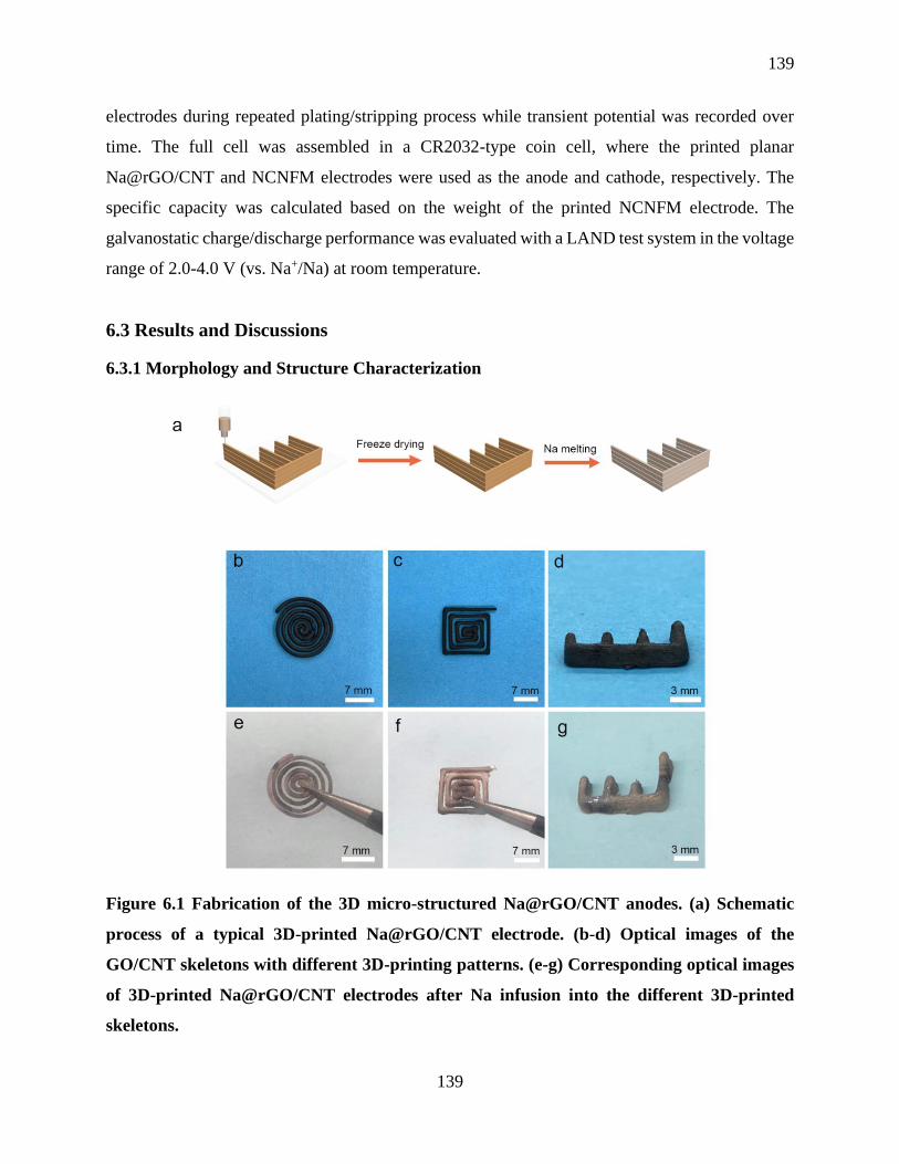
139
139
electrodes during repeated plating/stripping process while transient potential was recorded over
time. The full cell was assembled in a CR2032-type coin cell, where the printed planar
Na@rGO/CNT and NCNFM electrodes were used as the anode and cathode, respectively. The
specific capacity was calculated based on the weight of the printed NCNFM electrode. The
galvanostatic charge/discharge performance was evaluated with a LAND test system in the voltage
range of 2.0-4.0 V (vs. Na+/Na) at room temperature.
6.3 Results and Discussions
6.3.1 Morphology and Structure Characterization
Figure 6.1 Fabrication of the 3D micro-structured Na@rGO/CNT anodes. (a) Schematic
process of a typical 3D-printed Na@rGO/CNT electrode. (b-d) Optical images of the
GO/CNT skeletons with different 3D-printing patterns. (e-g) Corresponding optical images
of 3D-printed Na@rGO/CNT electrodes after Na infusion into the different 3D-printed
skeletons.

140
140
The fabrication process for the 3D micro-structured Na@rGO/CNT anodes is illustrated in Figure
6.1a. Typically, a 3D interdigitated GO/CNT structure was first printed through an extrusion-based
direct ink writing (DIW) method (detailed information seen from Experimental section) by using
a homogenous and concentrated GO-based suspension. The 3D printed interdigitated structure was
subsequently freeze-dried to obtain the GO/CNT aerogel skeleton. Due to the mechanically robust
properties of the 3D printed GO/CNT aerogel, 3D micro-structured Na@rGO/CNT electrodes can
be prepared after Na infusion into the space between the rGO sheets and the interdigitated skeleton
can be well maintained.39 The porous structure of the 3D Na@ rGO/CNT composite induced from
the freeze-drying process not only enabled the 3D Na electrodes with high-aspect-ratio, but also
reduced local current density, and mitigated the large volume expansion of the Na during the
plating/stripping process, which can effectively suppress the Na dendrite growth. Figure 6.1b-
6.1d shows the optical images of the 3D-printed GO/CNT skeletons with different patterns. Figure
6.1e-6.1f are the optical images of the obtained Na@rGO/CNT composite electrodes after Na
infusion into the different 3D-printed skeletons. It should be noted that all the Na@rGO/CNT
composite electrodes can maintain the shape of the GO/CNT skeleton very well.
Figure 6.2 Morphological characterizations of the 3D-printed architectures. Top-view SEM
images of the 3D-printed GO/CNT skeleton (a and b) and the 3D-printed Na@rGO/CNT
composite electrode (d and e). Cross-sectional SEM images of (c) 3D-printed GO/CNT and
(f) Na@rGO/CNT.

141
141
The morphologies and microstructures of the 3D-printed GO/CNT skeleton before and after Na
infusion were studied by scanning electron microscopy (SEM). Figure 6.2a shows the top-view
SEM of the printed GO/CNT interdigitated skeleton with a clear layer-by-layer structure, in which
each filament has the same diameter of around 200 µm. The adjacent filaments were closely
connected which was beneficial for maintaining the structure during the Na melting process. The
enlarged top-view SEM (Figure 6.2b) and cross-sectional SEM (Figure 6.2c) of the printed
GO/CNT skeleton showing a highly porous structure, where the pores with a diameter of tens of
micrometer are derived from the removal of water during the freeze-drying process. Figure 6.2d
and 6.2e displays the top-view SEM image of the Na@rGO/CNT skeleton after Na infused into
the GO/CNT. It can be clearly found that the Na uniformly covered the whole surface of the
skeleton, where the boundary of the filaments was disappeared because of the expansion of
graphene oxide and continuous coverage of the Na on the boundary during infusion process. More
importantly, the obtained Na@rGO/CNT skeleton still maintained the porous structure well, which
is essential for mitigating the huge volume change of Na during the plating/stripping process.
Figure 6.2f displays the cross-sectional SEM image of the Na@rGO/CNT. It can be observed that
the infused Na has partially filled the pores of GO/CNT skeleton, which could ensure a high
amount of Na in the composite and provide high areal capacity.

142
142
Figure 6.3 Morphology characterizations of the 3D-printed NCNFM cathode architectures.
a) Optical image of the 3D-printed interdigital patterned cathode. b) Cross-sectional SEM
image of the cathode electrode. c) High-magnification cross-sectional SEM image of the
electrode, indicating an internally porous structure. (d-f) Top-view SEM images of the
cathode electrode. (g-k) Elemental mappings of the Cu, Ni, Fe, and Mn distributed in the
cathode electrode.
After successfully printed the micro-structured Na composite electrode, we further fabricated
micro-structured cathode electrodes via the DIW method. Cu doped O3-NaCu1/9Ni2/9Fe3/9Mn3/9O2
(denoted as NCNFM) was used as the cathode material due to its high capacity, structural stability,
and moisture stability.40-41 The ink preparation process was based on our previous work,19 the
detailed information can be found from the experimental section (preparation of NCNFM ink).
Figure 6.3a shows the optical image of 3D printed interdigital patterned NCNFM cathode after
freeze-dried. The NCNFM electrode contained 12 layers and maintained the as-printed shape very
well with adjacent layers stacked together tightly. The morphologies of the printed NCNFM were
investigated by SEM. As seen from the cross-sectional SEM image in Figure 6.3b, the width of
the filament was approximately 200 µm, which is a little smaller than that of the printing nozzle.
The skeleton was constructed from two closely stacked layers, which can increase the structural
integrity of the whole electrode compared to one layer. The magnified SEM (Figure 6.3c)
displayed the detailed morphology within the filament. It can be found that the NCNFM particles
and conducting carbon were interconnected and forming a hierarchical porous structure after the
phase-inversion and removal of water during the freeze-drying process. From the surface-view
SEM image (Figure 6.3d), the printed NCNFM electrode presents an obvious layered structure,
in which the height of each filament is around 200 µm, and each layer is stacked tightly with a
clear boundary. The enlarged SEM images (Figure 6.3e and 6.3f) further revealed the porous and
interconnected conducting framework, which can facilitate the ion/electron transport within the
whole electrode.

143
143
6.3.2 Electrochemical Characterization
Figure 6.4 Cycling performance of symmetric cells with the 3D-printed rGO/CNT-Na and
Na foil electrodes at current densities of (a) 1mA cm-2 and (b) 3mA cm-2 with an areal
capacity of 1mAh cm-2. (c) Symmetric cell cycling performance at a current density of 3mA
cm-2 with a high areal capacity of 3 mAh cm-2.
To investigate the cycling stability of the printed Na composite anodes, the 3D-printed
Na@rGO/CNT electrode with a planar structure was fabricated and symmetric cells were used to
determine the cycling performance of the 3D-printed Na@rGO/CNT composite anode at different
current densities and charge/discharge time. Bare Na foil symmetric cells served as the control
group. Figure 6.4a displays the extended voltage profiles of the symmetric cells at a current
density of 1mA cm-2 with an areal capacity of 1mAh cm-2. As depicted, the 3D-printed
Na@rGO/CNT electrode exhibited a more stable voltage curve with a low voltage hysteresis for
more than 2000 h. In contrast, the voltage profile of the bare Na foil showed a gradually increased
voltage hysteresis and was only stable for over 200 h, which was caused by the formation of Na
dendrite. Further increasing the current density to 3 mA cm-2, the voltage hysteresis of bare Na foil
began increasing after 30 h and severe fluctuating voltage profiles occurs with overpotential rising
to around 150 mV after 230h as presented in Figure 6.4b. The increasing of voltage hysteresis and
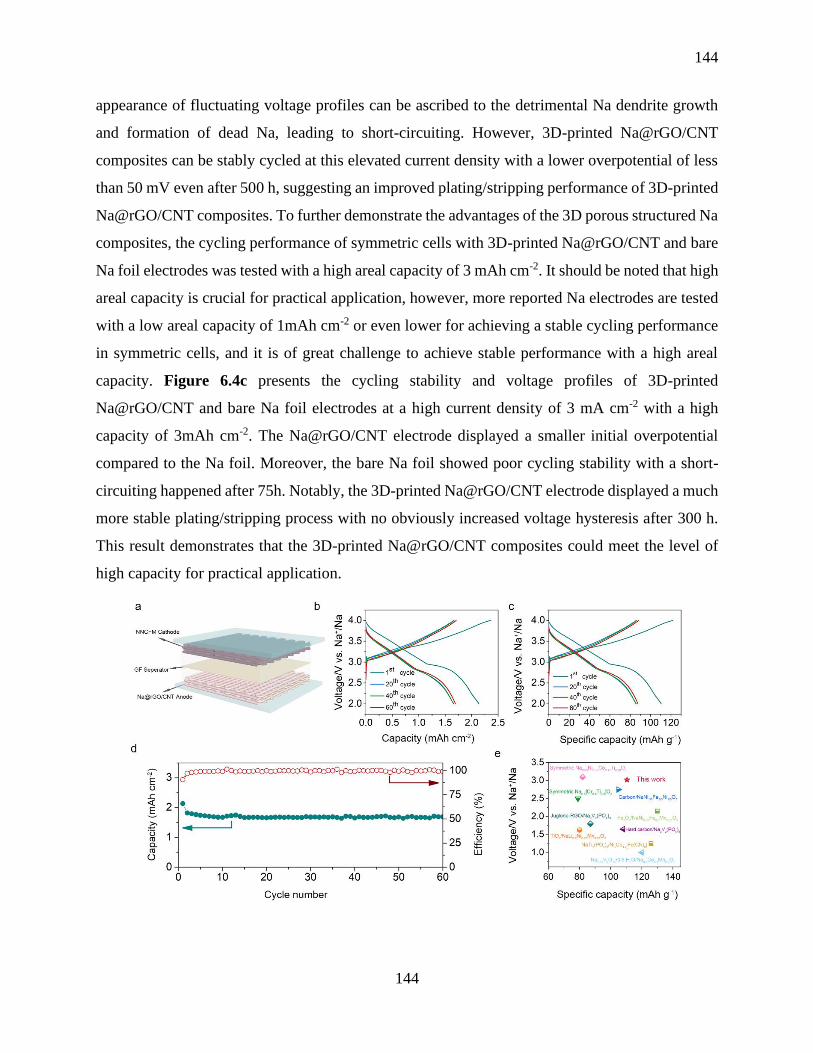
144
144
appearance of fluctuating voltage profiles can be ascribed to the detrimental Na dendrite growth
and formation of dead Na, leading to short-circuiting. However, 3D-printed Na@rGO/CNT
composites can be stably cycled at this elevated current density with a lower overpotential of less
than 50 mV even after 500 h, suggesting an improved plating/stripping performance of 3D-printed
Na@rGO/CNT composites. To further demonstrate the advantages of the 3D porous structured Na
composites, the cycling performance of symmetric cells with 3D-printed Na@rGO/CNT and bare
Na foil electrodes was tested with a high areal capacity of 3 mAh cm-2. It should be noted that high
areal capacity is crucial for practical application, however, more reported Na electrodes are tested
with a low areal capacity of 1mAh cm-2 or even lower for achieving a stable cycling performance
in symmetric cells, and it is of great challenge to achieve stable performance with a high areal
capacity. Figure 6.4c presents the cycling stability and voltage profiles of 3D-printed
Na@rGO/CNT and bare Na foil electrodes at a high current density of 3 mA cm-2 with a high
capacity of 3mAh cm-2. The Na@rGO/CNT electrode displayed a smaller initial overpotential
compared to the Na foil. Moreover, the bare Na foil showed poor cycling stability with a short-
circuiting happened after 75h. Notably, the 3D-printed Na@rGO/CNT electrode displayed a much
more stable plating/stripping process with no obviously increased voltage hysteresis after 300 h.
This result demonstrates that the 3D-printed Na@rGO/CNT composites could meet the level of
high capacity for practical application.

145
145
Figure 6.5 Electrochemical performance of the sodium metal full cell (a) Schematic
illustrating the assembled cell structure with printed Na@rGO/CNT anode and printed
NCNFM cathode. (b and c) The 1st, 20th, 40th, and 60th charge/discharge profiles of the full
cell with Na@rGO/CNT anode and NCNFM cathode. (d) Cycling performance of the full
cell with Na@rGO/CNT anode and NCNFM cathode. at 0.2C over 60 cycles. (e) Comparison
of current sodium metal full cell with those reported in literatures.
To further estimate the structural advantages of the printed electrodes in the full cell, we
investigated the electrochemical performance of the sodium metal full cell assembled with printed
electrodes. Figure 6.5a illustrate the full cell structure with printed Na@rGO/CNT and printed
NCNFM as the anode and the cathode, respectively. The current and capacity of the full cell were
determined by the mass of NCNFM in the printed cathode. In order to achieve high areal capacity,
a printed NCNFM electrode with mass loading of around 20 mg cm-2 was adopted as the cathode
in the full cell. Figure 6.5b and 6.5c present the charge/discharge profiles of the
Na@rGO/CNT||NCNFM full cell in different cycles. The initial cycle was measured at a lower
current density of 0.05C for activation and it could deliver a high specific capacity of 110.5 mAh
g-1 (corresponding to an areal capacity of 2.2 mAh cm-2). The subsequent cycles were examined
at 0.2C. As observed from the curves, it exhibited a higher capacity of 87.5 mAhg-1(corresponding
to an areal capacity of 1.7 mAh cm-2) even after 60 cycles. Figure 6.5d shows the cycling
performance of the full cell tested at 0.2 C over 60 cycles, which suggests impressive capacity
retention of approximately 93% (calculated based on the capacity in the 2nd cycle). The extremely
stable cycling performance of the full cell can be attributed the structural superiorities of the
printed electrodes. First, the printed micro-structured NCNFM cathode possesses a 3D porous
conducting network, which can enable fast electron and ion transport as well as facilitated
electrolyte penetration within the whole electrode. Second, the printed Na@rGO/CNT composite
anode with multiple porosities can effectively suppress the Na dendrite growth by decreasing the
local current density and releasing the volume change during the sodiation/desodiation process.
To estimate the standing of our Na@rGO/CNT||NCNFM full cell, we compare the electrochemical
performance of the printed Na@rGO/CNT||NCNFM full cell with that of other full cells recently
reported in the literature in terms of specific capacity and output voltage as shown in Figure 6.5e.40,
42-49 It clearly presents that our printed full cell outperforms most of the reported full cells with
146
146
regard to specific capacity and voltage. The results suggest that 3D printing provides a promising
strategy in fabricating 3D structured electrodes for achieving high-energy-density storage devices.
6.4 Conclusions
In summary, an extrusion-type 3D printing approach was first developed to construct a high-
performance SMB which was assembled by a printed Na@rGO/CNT anode and a printed NCNFM
cathode. The 3D-printed Na@rGO/CNT anode possesses multiple porosities, which could provide
abundant active reaction sites and enable fast Na+ transport. Moreover, the resultant 3D structured
Na@rGO/CNT can effectively suppress the Na dendrite growth by decreasing the local current
density and releasing the huge volume change of Na during cycling. As a result, the printed
Na@rGO/CNT composite can deliver extremely stable performance over 2000 h (~1000 cycles)
at a current density of 1 mA cm-2. Even with a high capacity of 3mAh cm-2, the Na@rGO/CNT
composite can still exhibit a long-lifetime of 300 h at a current density of 3 mA cm-2, which is
almost three times higher than that of the bare Na foil. On the other hand, the 3D-printed micro-
structured NCNFM cathode composed of interconnected CNTs and porous polymer framework
can enable fast electron and ion transport as well as facilitated electrolyte penetration within the
whole electrode. When the 3D-printed Na@rGO/CNT anode and the 3D-printed NCNFM cathode
were tested in a full cell, it delivered a higher initial specific capacity of 110.5 mAh g-1
(corresponding to an areal capacity of 2.2 mAh cm-2) and maintained impressive capacity retention
of approximately 93%. This work thus offers a promising approach to construct high-performance
Na-metal batteries, which can also be extended to develop next-generation high energy density
Na-S and Na-O2 batteries.
Acknowledgements
The work was supported by Natural Science Foundation of China (NSFC) (Grant U1432249), the
National Key R&D Program of China (Grant 2017YFA0205002), and the Priority Academic
Program Development (PAPD) of Jiangsu Higher Education Institutions. This is also a project
supported by Jiangsu Key Laboratory for Carbon-Based Functional Materials and Devices and
Collaborative Innovation Center of Suzhou Nano Science & Technology. This work was also
supported by the Natural Science and Engineering Research Council of Canada (NSERC), the

147
147
Canada Research Chair Program (CRC), the Canada Foundation for Innovation (CFI), and the
University of Western Ontario (UWO).
6.5 References
1. Forget, A.; Blaeser, A.; Miessmer, F.; Kopf, M.; Campos, D. F. D.; Voelcker, N. H.;
Blencowe, A.; Fischer, H.; Shastri, V. P., Mechanically Tunable Bioink for 3D Bioprinting of
Human Cells. Adv. Healthc. Mater. 2017, 6 (20).
2. Qian, F.; Zhu, C.; Knipe, J. M.; Ruelas, S.; Stolaroff, J. K.; DeOtte, J. R.; Duoss, E. B.;
Spadaccini, C. M.; Henard, C. A.; Guarnieri, M. T.; Baker, S. E., Direct Writing of Tunable Living
Inks for Bioprocess Intensification. Nano Lett. 2019.
3. Valentine, A. D.; Busbee, T. A.; Boley, J. W.; Raney, J. R.; Chortos, A.; Kotikian, A.;
Berrigan, J. D.; Durstock, M. F.; Lewis, J. A., Hybrid 3D Printing of Soft Electronics. Adv. Mater.
2017, 29 (40), 1703817.
4. Yang, H.; Leow, W. R.; Chen, X., 3D Printing of Flexible Electronic Devices. Small
Methods 2018, 2 (1), 1700259.
5. Gul, J. Z.; Sajid, M.; Rehman, M. M.; Siddiqui, G. U.; Shah, I.; Kim, K. H.; Lee, J. W.;
Choi, K. H., 3D Printing for Soft Robotics - A Review. Sci. Tech. Adv. Mater. 2018, 19 (1), 243-
262.
6. Liu, Y.; Zhang, B.; Xu, Q.; Hou, Y.; Seyedin, S.; Qin, S.; Wallace, G. G.; Beirne, S.; Razal,
J. M.; Chen, J., Development of Graphene Oxide/Polyaniline Inks for High Performance Flexible
Microsupercapacitors via Extrusion Printing. Adv. Funct. Mater. 2018, 28 (21), 1706592.
7. Tang, X.; Zhu, C.; Cheng, D.; Zhou, H.; Liu, X.; Xie, P.; Zhao, Q.; Zhang, D.; Fan, T.,
Architectured Leaf-Inspired Ni0.33Co0.66S2/Graphene Aerogels via 3D Printing for High-
Performance Energy Storage. Adv. Funct. Mater. 2018, 28 (51), 1805057.
148
148
8. Díaz-Marta, A. S.; Tubío, C. R.; Carbajales, C.; Fernández, C.; Escalante, L.; Sotelo, E.;
Guitián, F.; Barrio, V. L.; Gil, A.; Coelho, A., Three-Dimensional Printing in Catalysis:
Combining 3D Heterogeneous Copper and Palladium Catalysts for Multicatalytic Multicomponent
Reactions. ACS Catal. 2017, 8 (1), 392-404.
9. Ruiz-Morales, J. C.; Tarancón, A.; Canales-Vázquez, J.; Méndez-Ramos, J.; Hernández-
Afonso, L.; Acosta-Mora, P.; Marín Rueda, J. R.; Fernández-González, R., Three dimensional
printing of components and functional devices for energy and environmental applications. Energy
Environ. Sci. 2017.
10. Choi, K.-H.; Ahn, D. B.; Lee, S.-Y., Current Status and Challenges in Printed Batteries:
Toward Form Factor-Free, Monolithic Integrated Power Sources. ACS Energy Lett. 2017, 3 (1),
220-236.
11. Tay, Y. W. D.; Panda, B.; Paul, S. C.; Noor Mohamed, N. A.; Tan, M. J.; Leong, K. F., 3D
Printing Trends in Building and Construction Industry: A Review. Virtual Phys. Prototy. 2017, 12
(3), 261-276.
12. Dizon, J. R. C.; Espera, A. H.; Chen, Q.; Advincula, R. C., Mechanical Characterization of
3D-Printed Polymers. Addit. Manuf. 2018, 20, 44-67.
13. Nguyen, D. T.; Meyers, C.; Yee, T. D.; Dudukovic, N. A.; Destino, J. F.; Zhu, C.; Duoss,
E. B.; Baumann, T. F.; Suratwala, T.; Smay, J. E.; Dylla-Spears, R., 3D-Printed Transparent Glass.
Adv. Mater. 2017, 29 (26), 1701181-n/a.
14. Yan, P.; Brown, E.; Su, Q.; Li, J.; Wang, J.; Xu, C.; Zhou, C.; Lin, D., 3D Printing
Hierarchical Silver Nanowire Aerogel with Highly Compressive Resilience and Tensile
Elongation through Tunable Poisson's Ratio. Small 2017, 1701756-n/a.

149
149
15. Guo, S. Z.; Qiu, K.; Meng, F.; Park, S. H.; McAlpine, M. C., 3D Printed Stretchable Tactile
Sensors. Adv. Mater. 2017, 29 (27).
16. Ota, H.; Emaminejad, S.; Gao, Y.; Zhao, A.; Wu, E.; Challa, S.; Chen, K.; Fahad, H. M.;
Jha, A. K.; Kiriya, D.; Gao, W.; Shiraki, H.; Morioka, K.; Ferguson, A. R.; Healy, K. E.; Davis,
R. W.; Javey, A., Application of 3D Printing for Smart Objects with Embedded Electronic Sensors
and Systems. Adv. Mater. Tech. 2016, 1 (1), 1600013.
17. Zhang, C.; Shen, K.; Li, B.; Li, S.; Yang, S., Continuously 3D printed quantum dot-based
electrodes for lithium storage with ultrahigh capacities. J. Mater. Chem. A 2018, 6 (41), 19960-
19966.
18. Saleh, M. S.; Li, J.; Park, J.; Panat, R., 3D printed hierarchically-porous microlattice
electrode materials for exceptionally high specific capacity and areal capacity lithium ion batteries.
Addit. Manuf. 2018, 23, 70-78.
19. Wang, J.; Sun, Q.; Gao, X.; Wang, C.; Li, W.; Holness, F. B.; Zheng, M.; Li, R.; Price, A.
D.; Sun, X.; Sham, T. K.; Sun, X., Toward High Areal Energy and Power Density Electrode for
Li-Ion Batteries via Optimized 3D Printing Approach. ACS Appl. Mater. Interfaces 2018, 10 (46),
39794-39801.
20. Qiao, Y.; Liu, Y.; Chen, C.; Xie, H.; Yao, Y.; He, S.; Ping, W.; Liu, B.; Hu, L., 3D-Printed
Graphene Oxide Framework with Thermal Shock Synthesized Nanoparticles for Li-CO2 Batteries.
Adv. Funct. Mater. 2018, 28 (51), 1805899.
21. Lyu, Z.; Lim, G. J. H.; Guo, R.; Kou, Z.; Wang, T.; Guan, C.; Ding, J.; Chen, W.; Wang,
J., 3D-Printed MOF-Derived Hierarchically Porous Frameworks for Practical High-Energy
Density Li–O2 Batteries. Adv. Funct. Mater. 2019, 29 (1), 1806658.

150
150
22. Lacey, S. D.; Kirsch, D. J.; Li, Y.; Morgenstern, J. T.; Zarket, B. C.; Yao, Y.; Dai, J.; Garcia,
L. Q.; Liu, B.; Gao, T.; Xu, S.; Raghavan, S. R.; Connell, J. W.; Lin, Y.; Hu, L., Extrusion-Based
3D Printing of Hierarchically Porous Advanced Battery Electrodes. Adv. Mater. 2016, 1705651-
n/a.
23. Shen, K.; Mei, H.; Li, B.; Ding, J.; Yang, S., 3D Printing Sulfur Copolymer-Graphene
Architectures for Li-S Batteries. Adv. Energy Mater. 2018, 8 (4), 1701527.
24. Gao, X.; Sun, Q.; Yang, X.; Liang, J.; Koo, A.; Li, W.; Liang, J.; Wang, J.; Li, R.; Holness,
F. B.; Price, A. D.; Yang, S.; Sham, T.-K.; Sun, X., Toward a Remarkable Li-S battery via 3D
Printing. Nano Energy 2019, 56, 595-603.
25. Milroy, C.; Manthiram, A., Printed Microelectrodes for Scalable, High-Areal-Capacity
Lithium–Sulfur Batteries. Chem. Commun. 2016, 52 (23), 4282-4285.
26. Yao, B.; Chandrasekaran, S.; Zhang, J.; Xiao, W.; Qian, F.; Zhu, C.; Duoss, E. B.;
Spadaccini, C. M.; Worsley, M. A.; Li, Y., Efficient 3D Printed Pseudocapacitive Electrodes with
Ultrahigh MnO2 Loading. Joule 2019, 3 (2), 459-470.
27. Jiang, Y.; Xu, Z.; Huang, T.; Liu, Y.; Guo, F.; Xi, J.; Gao, W.; Gao, C., Direct 3D Printing
of Ultralight Graphene Oxide Aerogel Microlattices. Adv. Funct. Mater. 2018, 28 (16), 1707024.
28. Sun, K.; Wei, T. S.; Ahn, B. Y.; Seo, J. Y.; Dillon, S. J.; Lewis, J. A., 3D printing of
interdigitated Li-ion microbattery architectures. Adv. Mater. 2013, 25 (33), 4539-43.
29. Fu, K.; Wang, Y.; Yan, C.; Yao, Y.; Chen, Y.; Dai, J.; Lacey, S.; Wang, Y.; Wan, J.; Li,
T.; Wang, Z.; Xu, Y.; Hu, L., Graphene Oxide-Based Electrode Inks for 3D-Printed Lithium-Ion
Batteries. Adv. Mater. 2016, 28 (13), 2587-2594.
151
151
30. Cao, D.; Xing, Y.; Tantratian, K.; Wang, X.; Ma, Y.; Mukhopadhyay, A.; Cheng, Z.; Zhang,
Q.; Jiao, Y.; Chen, L.; Zhu, H., 3D Printed High-Performance Lithium Metal Microbatteries
Enabled by Nanocellulose. Adv. Mater. 2019, 31 (14), e1807313.
31. Zhao, Y.; Adair, K. R.; Sun, X., Recent Developments and Insights into the Understanding
of Na Metal Anodes for Na-Metal Batteries. Energy Environ. Sci. 2018, 11 (10), 2673-2695.
32. Zheng, X.; Bommier, C.; Luo, W.; Jiang, L.; Hao, Y.; Huang, Y., Sodium Metal Anodes
for Room-Temperature Sodium-Ion Batteries: Applications, Challenges and Solutions. Energy
Storage Mater. 2019, 16, 6-23.
33. Wang, T.-S.; Liu, Y.; Lu, Y.-X.; Hu, Y.-S.; Fan, L.-Z., Dendrite-free Na Metal
Plating/Stripping onto 3D Porous Cu Hosts. Energy Storage Mater. 2018, 15, 274-281.
34. Liu, S.; Tang, S.; Zhang, X.; Wang, A.; Yang, Q.-H.; Luo, J., Porous Al Current Collector
for Dendrite-Free Na Metal Anodes. Nano Lett. 2017, 17 (9), 5862-5868.
35. Chi, S.-S.; Qi, X.-G.; Hu, Y.-S.; Fan, L.-Z., 3D Flexible Carbon Felt Host for Highly Stable
Sodium Metal Anodes. Adv. Energy Mater., 1702764-n/a.
36. Luo, W.; Zhang, Y.; Xu, S.; Dai, J.; Hitz, E.; Li, Y.; Yang, C.; Chen, C.; Liu, B.; Hu, L.,
Encapsulation of Metallic Na in an Electrically Conductive Host with Porous Channels as a Highly
Stable Na Metal Anode. Nano Lett. 2017, 17 (6), 3792-3797.
37. Deng, W.; Zhou, X.; Fang, Q.; Liu, Z., Microscale Lithium Metal Stored inside Cellular
Graphene Scaffold toward Advanced Metallic Lithium Anodes. Adv. Energy Mater., 1703152-n/a.
38. Lin, D.; Liu, Y.; Liang, Z.; Lee, H. W.; Sun, J.; Wang, H.; Yan, K.; Xie, J.; Cui, Y., Layered
reduced graphene oxide with nanoscale interlayer gaps as a stable host for lithium metal anodes.
Nat. Nanotech. 2016, 11 (7), 626-32.

152
152
39. Wang, A.; Hu, X.; Tang, H.; Zhang, C.; Liu, S.; Yang, Y.-W.; Yang, Q.-H.; Luo, J.,
Processable and Moldable Sodium-Metal Anodes. Angew. Chem. Int. Ed. Engl. 2017, 56 (39),
11921-11926.
40. Kim, D.; Lee, E.; Slater, M.; Lu, W.; Rood, S.; Johnson, C. S., Layered
Na[Ni1/3Fe1/3Mn1/3]O2 Cathodes for Na-ion Battery Application. Electrochem. Commun. 2012, 18,
66-69.
41. Li, Y.; Yang, Z.; Xu, S.; Mu, L.; Gu, L.; Hu, Y.-S.; Li, H.; Chen, L., Air-Stable Copper-
Based P2-Na7/9Cu2/9Fe1/9Mn2/3O2 as a New Positive Electrode Material for Sodium-Ion Batteries.
Adv. Sci. 2015, 2 (6), 1500031-n/a.
42. Xiong, H.; Slater, M. D.; Balasubramanian, M.; Johnson, C. S.; Rajh, T., Amorphous TiO2
Nanotube Anode for Rechargeable Sodium Ion Batteries. J. Phys. Chem. Lett. 2011, 2 (20), 2560-
2565.
43. Oh, S. M.; Myung, S. T.; Yoon, C. S.; Lu, J.; Hassoun, J.; Scrosati, B.; Amine, K.; Sun, Y.
K., Advanced Na[Ni0.25Fe0.5Mn0.25]O2/C-Fe3O4 sodium-ion batteries using EMS electrolyte for
energy storage. Nano Lett. 2014, 14 (3), 1620-6.
44. Guo, S.; Liu, P.; Sun, Y.; Zhu, K.; Yi, J.; Chen, M.; Ishida, M.; Zhou, H., A High-Voltage
and Ultralong-Life Sodium Full Cell for Stationary Energy Storage. Angew. Chem. Int. Ed. Engl.
2015, 54 (40), 11701-5.
45. Wang, H.; Hu, P.; Yang, J.; Gong, G.; Guo, L.; Chen, X., Renewable-juglone-based high-
performance sodium-ion batteries. Adv. Mater. 2015, 27 (14), 2348-54.
46. Wang, Y.; Xiao, R.; Hu, Y.-S.; Avdeev, M.; Chen, L., P2-Na0.6[Cr0.6Ti0.4]O2 cation-
disordered electrode for high-rate symmetric rechargeable sodium-ion batteries. Nat. Commun.
2015, 6, 6954.

153
153
47. Yuan, Z.; Si, L.; Zhu, X., Three-dimensional hard carbon matrix for sodium-ion battery
anode with superior-rate performance and ultralong cycle life. J. Mater. Chem. A 2015, 3 (46),
23403-23411.
48. Peng, J.; Wang, J.; Yi, H.; Hu, W.; Yu, Y.; Yin, J.; Shen, Y.; Liu, Y.; Luo, J.; Xu, Y.; Wei,
P.; Li, Y.; Jin, Y.; Ding, Y.; Miao, L.; Jiang, J.; Han, J.; Huang, Y., A Dual-Insertion Type Sodium-
Ion Full Cell Based on High-Quality Ternary-Metal Prussian Blue Analogs. Adv. Energy Mater.
2018, 8 (11), 1702856.
49. Do, M. P.; Fischer, P. J.; Nagasubramanian, A.; Geder, J.; Kühn, F. E.; Srinivasan, M.,
Investigation of the Electrochemical and Thermal Stability of an Ionic Liquid Based
Na0.6Co0.1Mn0.9O2/Na2.55V6O16 Sodium-Ion Full-Cell. J. Electrochem. Soc. 2019, 166 (6), A944-
A952.

154
154
Chapter 7
7 Nanoscale Surface Modification of High-Voltage Layered Sodium Cathode via Atomic
Layer Deposition of Aluminum Phosphate with Enhanced Cycle Performance
Rechargeable sodium-ion batteries (SIBs) have been considered as promising candidate devices
for large-scale energy storage application due to the low cost and rich natural sources of Na.
Developing high-voltage cathodes is strategically pivotal to achieve a high-energy-density SIBs.
P2-type layered Na2/3Ni1/3Mn2/3O2 is considered a promising cathode owing to its high theoretical
capacity and operating voltage. However, it suffers from severe phase transition and unstable
cathode-electrolyte interface at high voltage. Herein, we report an electrochemically stable
nanoscale surface coating of AlPO4 on the Na2/3Ni1/3Mn2/3O2 with controllable thickness via
atomic layer deposition (ALD). By alleviating the severe structure change and protecting the
active materials from attack by the acidic environment, the AlPO4 coated Na2/3Ni1/3Mn2/3O2
electrodes show an enhanced cycling performance and rate capability. The electronic structure of
the system was examined using X-ray Absorption Near-Edge Structure (XANES). The findings in
this study underscore the significance of thickness controllable nanoscale coating layers and pave
the way for the development of high-voltage sodium cathode materials.
155
155
7.1 Introduction
Lithium-ion batteries (LIBs) are currently dominating the portable electronics market due to their
high specific capacity, good power density, and long cycle life.1-4 However, the increasing demand
for large-scale electrical energy storage (EES) applications such as electric vehicles (EVs) and
renewable power stations would bring great pressure on the limited lithium resources, thereby
causing a great surge of lithium price. Thus, new energy storage systems with reasonable price are
in desperate need and attracting a lot of research interests.5-6 7Sodium-ion batteries (SIBs) are
recently attracting much attention and considered as an ideal alternative to LIBs for large-scale
EES because of the rich natural resources and wide global distribution of sodium as well as similar
charge storage mechanism to LIBs.8 9Since the cathode materials are the bottleneck component
affecting the whole energy density, cost, and cycle life in a full cell, seeking of suitable cathode
materials is of crucial importance for the development of SIBs. 10
Within the past decade, many efforts have been devoted to developing high-performance sodium
cathode materials, such as layered metal oxides,11-12 pyrophosphate,13-14 olivine phosphates,
15fluorophosphates16, and fluorosulfates.17 Among the various cathode materials, sodium-based
layered metal oxides (NaxMO2, M= one or more transition metals) show great advantages
including high operating voltage, high theoretical capacity, and facile preparation. In particular,
P2-type Na2/3Ni1/3Mn2/3O2 has been extensively investigated due to its high theoretical capacity of
173 mAh g-1 and high operating voltage with a flat plateau above 4 V originated from the high
redox potential of Ni2+/Ni4+couple. Despite possessing such merits, some major problems remain
to be resolved during charge/discharge process: 1) A P2-O2 phase transition stemming from an
oxygen framework shift will take place during the cycling process when charged to a high voltage
of above 4.2 V, leading to a severe capacity decay. Meanwhile, an inevitable volume shrinkage of
around 23% associated with the phase transition will cause the isolation of active materials from
conducting materials, thus resulting in a fast capacity fading. 2) The carbonate-based electrolyte
tends to decompose when charged to the high voltage, generating detrimental contaminants, such
as HF. The acid thus produced can attack the active materials, leading to an inevitable capacity
degradation at high cut-off voltage. 18-19
156
156
Accordingly, numerous studies have focused on suppressing the irreversible phase transition by
partially substituting active metal elements with electrochemical inactive elements (Mg, Zn, Al,
Ti, etc.), which have been proved to be an effective way to stabilize the crystal structure, thus
enhancing the capacity retention.20-28 Although these doping attempts are promising, the
electrochemical performance is still not satisfactory as doping inactive ions will inevitably lose
some capacity. Recently, surface modification has been demonstrated to be a promising approach
to improve the electrochemical performances of sodium layered oxides. For example, our group
first reported atomic layer deposition (ALD) of Al2O3 on the layered P2-type
Na2/3(Mn0.54Ni0.13Co0.13)O2 (MNC) cathodes, the MNC electrode coated with 2 ALD cycles of
Al2O3 exhibits an enhanced electrochemical stability as the metal oxide coating layer provides
structural stability against mechanical stresses generated during the charge/discharge process.29
Later on, Zhou et al. introduced an Al2O3 coating layer on the P2- Na2/3Ni1/3Mn2/3O2 cathode to
stabilize the electrode at high voltage via a wet-chemistry method, and the coated electrode
displayed a high initial discharge capacity of 160 mAh g-1 with enhanced cycle retention of 73.2%
after 300 cycles. 30Alvarado et al.31 also demonstrated the ALD coating of Al2O3 on P2-
Na2/3Ni1/3Mn2/3O2 cathode. X-ray photoelectron (XPS) results revealed that the coated electrodes
contained polymeric species such as poly (ethylene oxide), which is beneficial for forming a more
flexible cathode-electrolyte interface (CEI) that can mitigate the exfoliation of Na2/3Ni1/3Mn2/3O2
particles. Although previous studies demonstrate that Al2O3 coating can enhance the cyclic
performance, a dense insulator Al2O3 layer would result in a decreased rate performance.
Additionally, Al2O3 is intrinsically unstable to an acid environment. Thus, we still face great
challenges with seeking a promising and electrochemically stable coating material.
Herein, we report a novel nanoscaled surface coating of alumina phosphate (AlPO4) on P2-
Na2/3Ni1/3Mn2/3O2 with well-controlled coating thickness via atomic layer deposition. Soft X-ray
absorption near-edge spectroscopy (XANES), which probes the local chemical change of the
element of interest, suggests that the surface coating layer has effectively protected the surface Ni
from being oxidized. The effect of ALD coating thickness on the electrochemical performance
including cycling performance and rate capabilities was investigated. The results clearly
demonstrate the positive impact of the ultrathin AlPO4 coating layer on the electrochemical
performance of P2- Na2/3Ni1/3Mn2/3O2.
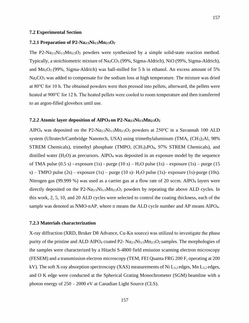
157
157
7.2 Experimental Section
7.2.1 Preparation of P2-Na2/3Ni1/3Mn2/3O2
The P2-Na2/3Ni1/3Mn2/3O2 powders were synthesized by a simple solid-state reaction method.
Typically, a stoichiometric mixture of Na2CO3 (99%, Sigma-Aldrich), NiO (99%, Sigma-Aldrich),
and Mn2O3 (99%, Sigma-Aldrich) was ball-milled for 5 h in ethanol. An excess amount of 5%
Na2CO3 was added to compensate for the sodium loss at high temperature. The mixture was dried
at 80 for 10 h. The obtained powders were then pressed into pellets, afterward, the pellets were
heated at 900 for 12 h. The heated pellets were cooled to room temperature and then transferred
to an argon-filled glovebox until use.
7.2.2 Atomic layer deposition of AlPO4 on P2-Na2/3Ni1/3Mn2/3O2
AlPO4 was deposited on the P2-Na2/3Ni1/3Mn2/3O2 powders at 250 in a Savannah 100 ALD
system (Ultratech/Cambridge Nanotech, USA) using trimethylaluminum (TMA, (CH3)3Al, 98%
STREM Chemicals), trimethyl phosphate (TMPO, (CH3)3PO4, 97% STREM Chemicals), and
distilled water (H2O) as precursors. AlPO4 was deposited in an exposure model by the sequence
of TMA pulse (0.5 s) - exposure (1s) - purge (10 s) – H2O pulse (1s) – exposure (1s) – purge (15
s) – TMPO pulse (2s) – exposure (1s) – purge (10 s)- H2O pulse (1s)- exposure (1s)-purge (10s).
Nitrogen gas (99.999 %) was used as a carrier gas at a flow rate of 20 sccm. AlPO4 layers were
directly deposited on the P2-Na2/3Ni1/3Mn2/3O2 powders by repeating the above ALD cycles. In
this work, 2, 5, 10, and 20 ALD cycles were selected to control the coating thickness, each of the
sample was denoted as NMO-nAP, where n means the ALD cycle number and AP means AlPO4.
7.2.3 Materials characterization
X-ray diffraction (XRD, Bruker D8 Advance, Cu-Kα source) was utilized to investigate the phase
purity of the pristine and ALD AlPO4 coated P2- Na2/3Ni1/3Mn2/3O2 samples. The morphologies of
the samples were characterized by a Hitachi S-4800 field emission scanning electron microscopy
(FESEM) and a transmission electron microscopy (TEM, FEI Quanta FRG 200 F, operating at 200
kV). The soft X-ray absorption spectroscopy (XAS) measurements of Ni L3,2 edges, Mn L3,2 edges,
and O K edge were conducted at the Spherical Grating Monochrometer (SGM) beamline with a
photon energy of 250 – 2000 eV at Canadian Light Source (CLS).

158
158
7.2.4 Electrochemical performance measurements
The electrodes were prepared by mixing active material, acetylene black (AB) and poly
(vinylidene fluoride) (PVDF) in a ratio of 80:10:10 in N-methyl-pyrrolidone (NMP). The slurry
was then pasted on Al foils and dried at 80 under vacuum for overnight. Subsequently, the dried
electrode was punched and assembled into a CR-2032coin cell in an argon-filled glovebox.
Sodium metal was used as the counter electrode. 0.5 M NaPF6 dissolved into propylene carbonate
(PC, 2% FEC) was used as the electrolyte. Glass fiber (GF) was used as the separator. Cyclic
voltammetry (CV) and electrochemical impedance spectroscopic (EIS) measurements were
performed on a Bio-Logic multichannel potentiostat 3/Z (VMP3). The cells were tested on a Land
system between a voltage range of 2.0-4.3 V vs. Na+/Na at room temperature.
7.3 Results and Discussions
7.3.1 Morphology and Structure Characterization
Figure 7.1 a) XRD patterns of pristine NMO and AlPO4-coated NMO samples; Typical
SEM images of b) bare NMO, c) NMO-2AP, d) NMO-5AP, e) NMO-10AP, and f) NMO-
20AP.
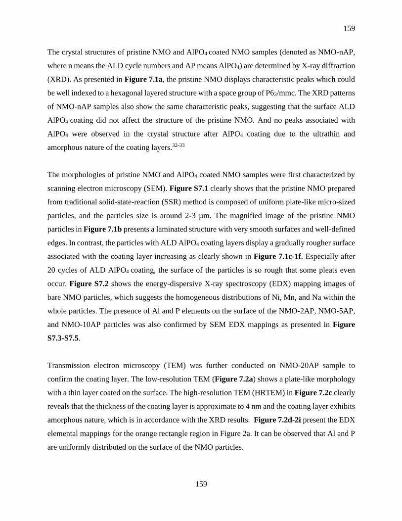
159
159
The crystal structures of pristine NMO and AlPO4 coated NMO samples (denoted as NMO-nAP,
where n means the ALD cycle numbers and AP means AlPO4) are determined by X-ray diffraction
(XRD). As presented in Figure 7.1a, the pristine NMO displays characteristic peaks which could
be well indexed to a hexagonal layered structure with a space group of P63/mmc. The XRD patterns
of NMO-nAP samples also show the same characteristic peaks, suggesting that the surface ALD
AlPO4 coating did not affect the structure of the pristine NMO. And no peaks associated with
AlPO4 were observed in the crystal structure after AlPO4 coating due to the ultrathin and
amorphous nature of the coating layers.32-33
The morphologies of pristine NMO and AlPO4 coated NMO samples were first characterized by
scanning electron microscopy (SEM). Figure S7.1 clearly shows that the pristine NMO prepared
from traditional solid-state-reaction (SSR) method is composed of uniform plate-like micro-sized
particles, and the particles size is around 2-3 µm. The magnified image of the pristine NMO
particles in Figure 7.1b presents a laminated structure with very smooth surfaces and well-defined
edges. In contrast, the particles with ALD AlPO4 coating layers display a gradually rougher surface
associated with the coating layer increasing as clearly shown in Figure 7.1c-1f. Especially after
20 cycles of ALD AlPO4 coating, the surface of the particles is so rough that some pleats even
occur. Figure S7.2 shows the energy-dispersive X-ray spectroscopy (EDX) mapping images of
bare NMO particles, which suggests the homogeneous distributions of Ni, Mn, and Na within the
whole particles. The presence of Al and P elements on the surface of the NMO-2AP, NMO-5AP,
and NMO-10AP particles was also confirmed by SEM EDX mappings as presented in Figure
S7.3-S7.5.
Transmission electron microscopy (TEM) was further conducted on NMO-20AP sample to
confirm the coating layer. The low-resolution TEM (Figure 7.2a) shows a plate-like morphology
with a thin layer coated on the surface. The high-resolution TEM (HRTEM) in Figure 7.2c clearly
reveals that the thickness of the coating layer is approximate to 4 nm and the coating layer exhibits
amorphous nature, which is in accordance with the XRD results. Figure 7.2d-2i present the EDX
elemental mappings for the orange rectangle region in Figure 2a. It can be observed that Al and P
are uniformly distributed on the surface of the NMO particles.

160
160
Figure 7.2 a) Low-resolution TEM image, b) and c) HRTM images; (d-i) elemental
mapping of Na, Ni, Mn, O, Al, and P of the NMO-20AP, respectively.
To investigate whether the thin surface coating layer affects the valence states and electronic
structures of Ni and Mn in the pristine NMO, soft X-ray absorption spectroscopy (XAS) was used
to obtain the XANES on the Mn L3,2-edges and Ni L3,2-edges for bare NMO and NMO-10AP
samples (Figure 7.3a and 7.3b) in total electron yield (TEY) mode, which has a surface probing
depth of a few nm. Metal L3,2-edges usually reveal the electronic transition from M 2p3/2 and 2p1/2
to an unoccupied 3d states, and the peaks corresponding to L3,2 edges are very sensitive to
oxidation state, spin state, local symmetry (e.g. tetrahedral vs octahedral) and bond covalence.
Both Mn L-edge and Ni L-edge spectra show a negligible difference before and after surface
coating, indicating that the ALD thin coating layer did not alter the surface oxidation state of Ni
and Mn in the NMO nor its local structure. Compared with the standard MnO2 and NiO XANES
features, it can be revealed that the valence state of Mn and Ni in both samples are primarily Mn4+
and Ni2+, respectively34

161
161
The O K-edge can be divided into two regions. Pre-edge peaks below 535 eV are ascribed to
electronic transition from O 1s state to O 2p-TM 3d hybridized state of eg and t2g character. The
broad peaks above 535 eV correspond to transition to O 2p-TM 4sp hybridized state. The O K-
edge spectra of bare NMO and NMO-10AP samples are both collected in TEY and fluorescence
yield (FY) modes, the latter is sensitive to the bulk while TEY is sensitive to the surface with
contributions from both the AlPO4 coating and the electrode materials. As shown in Figure 7.3c,
the O K-edge of two samples in FY mode display similar features, suggesting that the coating did
not affect the bulk electronic structures of NMO. Figure 7.3d shows the O K-edge in TEY mode,
the pre-edge peak of NMO-10AP at around 530 eV shows a reduced intensity compared with that
of the bare NMO, which indicates that surface coating layer can avoid the oxidization of surface
Ni as the intensity decrease of this pre-edge peak means fewer holes in the O 2p-TM 3d hybridized
orbitals, suggesting a lower valence state of the surface metals.35 It should be noted that AlPO4
exhibits no absorption features at 530 eV of its O K-edge XANES but a broad absorption at ~ 540
eV which contributes to the background in the XANES of the coated samples in this energy region.

162
162
Figure 7.3 a) XAS spectra of Mn L3,2-edges and Ni L3,2 edges of bare NMO, NMO-10AP, and
standard MnO2; b) XAS spectra of Ni L3,2-edges of NMO, NMO-10AP, and standard NiO
collected in TEY mode; c) and d) O K-edges of bare NMO and NMO-10AP collected in FY
and TEY modes, respectively.
7.3.2 Electrochemical Characterization
Figure 7.4 Cyclic voltammetry of a) bare NMO, b) NMO-2AP, c) NMO-5AP, d) NMO-10AP,
and (e) NMO-20AP.
To study the electrochemical behaviors of bare NMO and NMO coated with various ALD cycles
of AlPO4, cyclic voltammetry (CV) measurements were first conducted at a scanning rate of
0.1mV s-1 within a voltage range of 2.0 – 4.3V. As shown in Figure 7.4, three main pairs of redox
peaks can be observed in the CV curves for all the samples, corresponding to the charge/discharge
plateaus of the voltage profiles. The reversible oxidation/reduction peaks at around 3.37/3.25V
and 3.75/3.52V are attributed to the redox reactions of Ni2+/Ni3+ and Ni3+/Ni4+, respectively. 36 A
higher redox peak appeared at around 4.0/4.22V can be ascribed to the phase transition from P2 to
O2, which will cause the layered structures gliding and thus lead to a decreased cycle stability.37
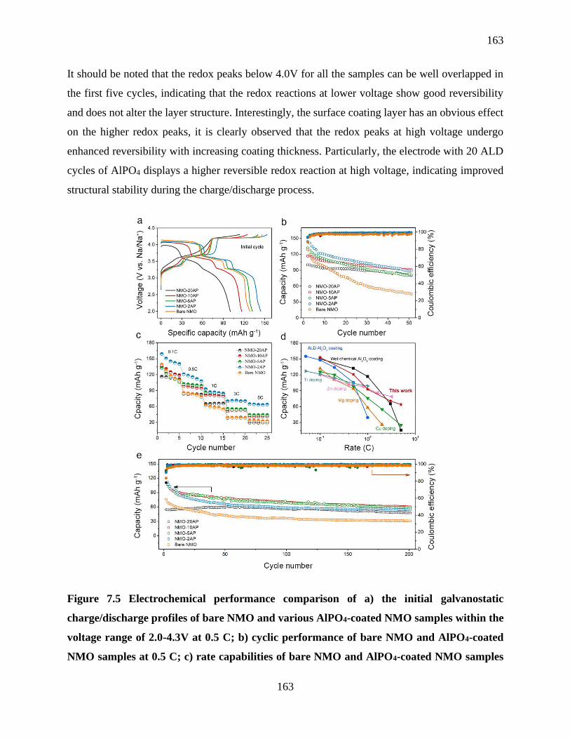
163
163
It should be noted that the redox peaks below 4.0V for all the samples can be well overlapped in
the first five cycles, indicating that the redox reactions at lower voltage show good reversibility
and does not alter the layer structure. Interestingly, the surface coating layer has an obvious effect
on the higher redox peaks, it is clearly observed that the redox peaks at high voltage undergo
enhanced reversibility with increasing coating thickness. Particularly, the electrode with 20 ALD
cycles of AlPO4 displays a higher reversible redox reaction at high voltage, indicating improved
structural stability during the charge/discharge process.
Figure 7.5 Electrochemical performance comparison of a) the initial galvanostatic
charge/discharge profiles of bare NMO and various AlPO4-coated NMO samples within the
voltage range of 2.0-4.3V at 0.5 C; b) cyclic performance of bare NMO and AlPO4-coated
NMO samples at 0.5 C; c) rate capabilities of bare NMO and AlPO4-coated NMO samples
164
164
at various current densities; d) A comparison of the rate performance between this work and
the work previously reported in the literature; e) The long-term cyclic performance of bare
NMO and AlPO4-coated NMO samples over 200 cycles at a rate of 2C.
The sodium storage performance of bare NMO and AlPO4 coated NMO samples were evaluated
in coin cells with Na metal as the counter electrode. The initial charge/discharge voltage profiles
of bare NMO and various ALD-coated NMO electrodes measured at 0.5C are displayed in Figure
7.5a. All of the electrodes show three obvious slopes and voltage plateaus during the
charge/discharge process, which are consistent with the CV results. As indicated in Figure 7.5a,
an initial discharge capacity of approximately 128 mAh g-1 was obtained from the bare NMO
electrode within the voltage range of 2.0-4.3V, whereas the NMO-2AP electrode exhibited an
enhanced initial discharge capacity of 144.2 mAh g-1, which suggests that the ultrathin coating
layer might facilitate the Na diffusion. However, the initial discharge capacities of the NMO-5AP,
NMO-10AP, and NMO-20AP electrodes are 140, 119, and 95 mAg g-1, respectively, which
presents a linearly decrease with the coating thickness increasing. This phenomenon can be
ascribed to the thicker inactive AlPO4 layer restricting the Na ions diffusion from the electrolyte
into the bulk active material, which inevitably reduces the activity of active species in the
electrochemical reaction.19, 38As a consequence, the 20 cycles of ALD-coated NMO electrode
delivered a greatly reduced initial capacity and coulombic efficiency.
To further investigate the coating effects on cycling stability, the cycling performance of various
NMP-nAP electrodes was examined at 0.5C over 50 cycles. It is displayed in Figure 7.5b that the
bare NMO electrode suffered from a dramatic capacity fading with only 48% capacity retention
after 50 cycles. This rapidly capacity decay resulted from the severe structural changes during the
charge/discharge process, which is consistent with previous reports.37In contrast, the ALD-coated
electrodes show improved capacity retention compared to the uncoated electrode. In should be
noted that the capacity retention of the coated electrodes demonstrates a linearly increases with the
increasing coating thickness. Among all the coated electrodes, the electrode with 10 cycles of ALD
coating shows the best discharge capacity of around 94 mAh g-1 at the 50th cycle with capacity
retention of 78%. It is worth to note that the 20 cycles of ALD-coated electrode displayed superior
cyclic stability with 80% capacity remaining at 50th cycle although it presented a lower initial

165
165
discharge capacity. The improved cyclic stability of the coated electrodes might be attributed to
the existing of the stable coating layer, which could suppress the electrolyte oxidation under high
voltage and mitigate the exfoliation of NMO particles. 39-41
Furthermore, the rate capabilities of the bare NMO electrode and ALD AlPO4 coated electrodes
were compared at various current densities as displayed in Figure 7.5c and Figure S7.6. It can be
observed that the bare NMO, NMO-2AP, NMO-5AP, and NMO-10AP electrodes all undergo a
fast capacity decay in the first five cycles at 0.1C, which is caused by the irreversible structural
change. However, the NMO-20AP electrode revealed a relatively stable cyclic performance,
indicating that 20 cycles of coating layer could effectively mitigate the structural change.
Comparing the overall rate- performance results, it can be found that the NMO-2AP electrode
exhibits a higher capacity than those of the bare NMO and other coated NMO electrodes,
suggesting an enhanced ion transport. High capacity of approximately 70 mAh g-1 was obtained
for 2 cycles of the ALD-coated electrode at a high rate of 5C. However, the 20 cycles of coated
electrode presented a greatly reduced rate capability, which might be a result of the high Na ion
resistance of the thick insulating coating layer. Figure 7.5d compares the rate capabilities of this
work with previously reported data in the literature. It clearly reveals that doping inactive elements
greatly reduce the capacity of the NMO electrodes, on the contrary, surface coated NMO electrodes
could maintain a higher capacity. Moreover, compared with Al2O3 coating reported in the literature,
ALD AlPO4 coated NMO electrode in this work displays superior capacity, especially at a high C-
rate.
The long-term cyclic performance at a high current density is essential for practical application of
the energy storage devices. Thus, the long-term cycle stability of various NMO-nAP electrodes
was tested at a high rate of 2C over 200 cycles. As shown in Figure 7.5e and Figure S7.7, the 2
cycles of ALD-coated NMO exhibits the highest initial discharge capacity of 121.2 mAh g-1 among
all the electrodes. In contrast, the bare NMO electrode only delivers an initial discharge capacity
of 76.2 mAh g-1, with only 40.3% of the initial capacity remained after 200 cycles. Notably, all the
coated electrodes exhibit enhanced cycle stability as shown in Figure S7.8. It is worth noting that
the NMO-10AP electrode delivers a high capacity of 60 mAh g-1 at the 200th cycle, which is almost
twice that of the bare NMO.

166
166
Figure 7.6 Cyclic voltammogram curves of (a) NMO-2AP and (c) bare NMO electrodes at
various scanning rates (0.1, 0.2, 0.4, 0.6, 0.8, 1.0, 1.2, and 1.4 mVs-1); (b) and (d) are the
corresponding linear relationship between the peak current and the square root of the scan
rates; (e) and (f) are EIS curves after 10 cycles and 50 cycles.
To better understand the high-rate capabilities of AlPO4-coated electrodes. CV measurements with
varied scan rates were investigated to study the kinetic behavior of the bare and coated NMO.
Figure 7.6a and 7.6c are the CV profiles of the bare and NMO-2AP electrodes, respectively.
Figure 7.6b and 7.6d show the corresponding linear relationship between the peak current and
the square root of the scan rates. The Na diffusion coefficients (DNa) values can be calculated
according to the Randles-Sevick equation42-43:
Ip = 2.69 × 10⁵ n3/2AD1/2v1/2C0 (1)
Where Ip is the peak current of anodic or cathodic peaks, n is the number of electrons per formula
during the insertion, A is the geometric area of the electrode, D is the Na diffusion coefficient, v
is the scan rate and C0 is the concentration of Na+ in the electrode. The average DNa values of bare
NMO and NMO-2AP samples are 1.97×10⁻¹¹cm2 s-1 and 3.86×10⁻¹¹cm2 s-1 during the charging
process, respectively. The improved DNa value of the 2 cycles of ALD-coated electrode
should be one of the reasons for the enhanced rate capacities and cycling performance.

167
167
In order to study the effect of the AlPO4 coating layer on the formation of solid electrolyte interface
(SEI), electrochemical impedance spectra (EIS) measurements were conducted on bare NMO and
coated NMO electrodes after different cycling at 0.5C. The Nyquist plots and a fitted equivalent
circuit are shown in Figure 7.6e and 7.6f. In particular, the semicircle at high frequency stands
for the Na+ migration resistance (Rs) through the surface layer, which reflects the resistance of
SEI. The semicircle at medium frequency can be assigned to the charge transfer resistance (Rct)
at the cathode-electrolyte interface. The inclined line at low frequency (Warburg impedance Zw)
is related to the Na+ diffusion into the bulk of the electrode materials. The values of the Rs for each
sample after different cycles are listed in Table S7.1, it can be seen that bare NMO exhibits a
larger Rs value of 336.1 Ω after 10 cycles, whereas the AlPO4 coated NMO shows a decreased Rs
value of 218.5 Ω, suggesting a smaller SEI impedance (Figure 6e). This also indicates that the
AlPO4 coating could suppress the electrolyte decomposition, which is mainly because that the
AlPO4 layer could protect the active materials from direct contact with the electrolyte. Moreover,
the Rs of the bare NMO electrode increased to 485.9 Ω after 50 cycles, whereas the increase of Rs
impedance was negligible for AlPO4 coated NMO electrode. The impedance comparison
demonstrates that the AlPO4 coating layer is effective for stabilization of the cathode-electrolyte
interface, leading to a thinner SEI on the electrode compared to the bare NMO electrode. These
results reveal that the nanoscale surface coating could effectively improve the electrochemical
performance of the pristine electrode.
7.3.3 Post-cycling Characterization
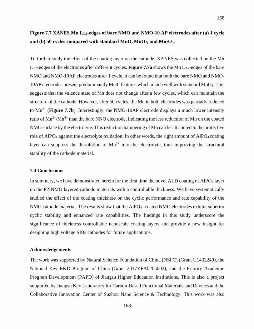
168
168
Figure 7.7 XANES Mn L3,2-edges of bare NMO and NMO-10 AP electrodes after (a) 1 cycle
and (b) 50 cycles compared with standard MnO, MnO2, and Mn2O3.
To further study the effect of the coating layer on the cathode, XANES was collected on the Mn
L3,2-edges of the electrodes after different cycles. Figure 7.7a shows the Mn L3,2-edges of the bare
NMO and NMO-10AP electrodes after 1 cycle, it can be found that both the bare NMO and NMO-
10AP electrodes present predominantly Mn4+ features which match well with standard MnO2. This
suggests that the valence state of Mn does not change after a few cycles, which can maintain the
structure of the cathode. However, after 50 cycles, the Mn in both electrodes was partially reduced
to Mn2+ (Figure 7.7b). Interestingly, the NMO-10AP electrode displays a much lower intensity
ratio of Mn2+/Mn4+ than the bare NNO electrode, indicating the less reduction of Mn on the coated
NMO surface by the electrolyte. This reduction hampering of Mn can be attributed to the protective
role of AlPO4 against the electrolyte oxidation. In other words, the right amount of AlPO4 coating
layer can suppress the dissolution of Mn2+ into the electrolyte, thus improving the structural
stability of the cathode material.
7.4 Conclusions
In summary, we have demonstrated herein for the first time the novel ALD coating of AlPO4 layer
on the P2-NMO layered cathode materials with a controllable thickness. We have systematically
studied the effect of the coating thickness on the cyclic performance and rate capability of the
NMO cathode material. The results show that the AlPO4 -coated NMO electrodes exhibit superior
cyclic stability and enhanced rate capabilities. The findings in this study underscore the
significance of thickness controllable nanoscale coating layers and provide a new insight for
designing high voltage SIBs cathodes for future applications.
Acknowledgements
The work was supported by Natural Science Foundation of China (NSFC) (Grant U1432249), the
National Key R&D Program of China (Grant 2017YFA0205002), and the Priority Academic
Program Development (PAPD) of Jiangsu Higher Education Institutions. This is also a project
supported by Jiangsu Key Laboratory for Carbon-Based Functional Materials and Devices and the
Collaborative Innovation Center of Suzhou Nano Science & Technology. This work was also
169
169
supported by the Natural Science and Engineering Research Council of Canada (NSERC), the
Canada Research Chair Program (CRC), the Canada Foundation for Innovation (CFI), and the
University of Western Ontario (UWO). Synchrotron measurements were conducted at the
Canadian Light Source (CLS), which is supported by National Research Council of Canada (NRC),
Canada Foundation for Innovation (CFI), Canadian Institute of Health Research (CIHR), NSERC
and the University of Saskatchewan, Jiwei Wang acknowledges the support of a travel grant by
CLS.
7.5 References
1. Bruce, P. G.; Scrosati, B.; Tarascon, J. M., Nanomaterials for rechargeable lithium batteries.
Angew. Chem. Int. Ed. 2008, 47 (16), 2930-46.
2. Tarascon, J. M.; Armand, M., Issues and challenges facing rechargeable lithium batteries.
Nature 2001, 414, 359.
3. Gao, X.; Wang, J.; Zhang, D.; Nie, K.; Ma, Y.; Zhong, J.; Sun, X., Hollow NiFe2O4
Nanospheres on Carbon Nanorods as A Highly Efficient Anode Material for Lithium-Ion Batteries.
J. Mater. Chem. A 2017, 5, 5007-5012.
4. Gao, X.; Wang, J.; Zhang, D.; Adair, K.; Feng, K.; Sun, N.; Zheng, H.; Shao, H.; Zhong,
J.; Ma, Y.; Sun, X.; Sun, X., Carbon coated bimetallic sulfide nanodots/carbon nanorod
heterostructure enabling long-life lithium-ion batteries. J. Mater. Chem. A 2017, 5 (48), 25625-
25631.
5. Hwang, J.-Y.; Myung, S.-T.; Sun, Y.-K., Sodium-ion batteries: present and future. Chem.
Soc. Rew. 2017, 46 (12), 3529-3614.
6. Sung-Wook, K.; Dong-Hwa, S.; Xiaohua, M.; Gerbrand, C.; Kisuk, K., Electrode Materials
for Rechargeable Sodium-Ion Batteries: Potential Alternatives to Current Lithium-Ion Batteries.
Adv. Energy Mater. 2012, 2 (7), 710-721.
170
170
7. D., S. M.; Donghan, K.; Eungje, L.; S., J. C., Sodium-Ion Batteries. Adv. Funct. Mater.
2013, 23 (8), 947-958.
8. Pan, H.; Hu, Y.-S.; Chen, L., Room-temperature stationary sodium-ion batteries for large-
scale electric energy storage. Energy Environ. Sci. 2013, 6 (8), 2338-2360.
9. Shinichi, K.; Wataru, M.; Toru, I.; Naoaki, Y.; Tomoaki, O.; Tetsuri, N.; Atsushi, O.;
Kazuma, G.; Kazuya, F., Electrochemical Na Insertion and Solid Electrolyte Interphase for Hard-
Carbon Electrodes and Application to Na-Ion Batteries. Adv. Funct. Mater. 2011, 21 (20), 3859-
3867.
10. Xiang, X.; Zhang, K.; Chen, J., Recent Advances and Prospects of Cathode Materials for
Sodium-Ion Batteries. Adv. Mater. 2015, 27 (36), 5343-5364.
11. Han, M. H.; Gonzalo, E.; Singh, G.; Rojo, T., A comprehensive review of sodium layered
oxides: powerful cathodes for Na-ion batteries. Energy Environ. Sci. 2015, 8 (1), 81-102.
12. Ortiz Vitoriano, N.; Drewett, N.; Gonzalo, E.; Rojo, T., High Performance Manganese-
based Layered Oxide Cathodes: Overcoming the Challenges of Sodium Ion Batteries. Energy
Environ. Sci. 2017.
13. Ni, Q.; Bai, Y.; Wu, F.; Wu, C., Polyanion-Type Electrode Materials for Sodium-Ion
Batteries. Adv. Sci. 2017, 4 (3), 1600275-n/a.
14. Tamaru, M.; Chung, S. C.; Shimizu, D.; Nishimura, S.-i.; Yamada, A., Pyrophosphate
Chemistry toward Safe Rechargeable Batteries. Chem. Mater. 2013, 25 (12), 2538-2543.
15. Casas-Cabanas, M.; Roddatis, V. V.; Saurel, D.; Kubiak, P.; Carretero-González, J.;
Palomares, V.; Serras, P.; Rojo, T., Crystal chemistry of Na insertion/deinsertion in FePO4–
NaFePO4. J. Mater. Chem. 2012, 22 (34), 17421-17423.

171
171
16. Tripathi, R.; Wood, S. M.; Islam, M. S.; Nazar, L. F., Na-ion mobility in layered
Na2FePO4F and olivine Na[Fe,Mn]PO4. Energy Environ. Sci. 2013, 6 (8), 2257-2264.
17. Barpanda, P.; Oyama, G.; Nishimura, S.-i.; Chung, S.-C.; Yamada, A., A 3.8-V earth-
abundant sodium battery electrode. Nat. Commun. 2014, 5, 4358.
18. Li, X.; Liu, J.; Banis, M. N.; Lushington, A.; Li, R.; Cai, M.; Sun, X., Atomic layer
deposition of solid-state electrolyte coated cathode materials with superior high-voltage cycling
behavior for lithium ion battery application. Energy Environ. Sci. 2014, 7 (2), 768-778.
19. Xiao, B.; Liu, J.; Sun, Q.; Wang, B.; Banis, M. N.; Zhao, D.; Wang, Z.; Li, R.; Cui, X.;
Sham, T. K.; Sun, X., Unravelling the Role of Electrochemically Active FePO4 Coating by Atomic
Layer Deposition for Increased High-Voltage Stability of LiNi0.5Mn1.5O4 Cathode Material. Adv.
Sci. 2015, 2 (5), 1500022.
20. Wang, P. F.; You, Y.; Yin, Y. X.; Wang, Y. S.; Wan, L. J.; Gu, L.; Guo, Y. G., Suppressing
the P2-O2 Phase Transition of Na0.67 Mn0.67 Ni0.33 O2 by Magnesium Substitution for Improved
Sodium-Ion Batteries. Angew. Chem. Int. Ed. Engl. 2016, 55 (26), 7445-9.
21. Singh, G.; Tapia-Ruiz, N.; Lopez del Amo, J. M.; Maitra, U.; Somerville, J. W.; Armstrong,
A. R.; Martinez de Ilarduya, J.; Rojo, T.; Bruce, P. G., High Voltage Mg-Doped Na0.67Ni0.3–
xMgxMn0.7O2 (x = 0.05, 0.1) Na-Ion Cathodes with Enhanced Stability and Rate Capability. Chem.
Mater. 2016, 28 (14), 5087-5094.
22. Hemalatha, K.; Jayakumar, M.; Bera, P.; Prakash, A. S., Improved electrochemical
performance of Na0.67MnO2 through Ni and Mg substitution. J. Mater. Chem. A 2015, 3 (42),
20908-20912.

172
172
23. Wu, X.; Guo, J.; Wang, D.; Zhong, G.; McDonald, M. J.; Yang, Y., P2-type Na0.66Ni0.33–
xZnxMn0.67O2 as new high-voltage cathode materials for sodium-ion batteries. J. Power Sources
2015, 281, 18-26.
24. Hasa, I.; Passerini, S.; Hassoun, J., Toward high energy density cathode materials for
sodium-ion batteries: investigating the beneficial effect of aluminum doping on the P2-type
structure. J. Mater. Chem. A 2017, 5 (9), 4467-4477.
25. Pang, W.-L.; Zhang, X.-H.; Guo, J.-Z.; Li, J.-Y.; Yan, X.; Hou, B.-H.; Guan, H.-Y.; Wu,
X.-L., P2-type Na2/3Mn1-xAlxO2 cathode material for sodium-ion batteries: Al-doped enhanced
electrochemical properties and studies on the electrode kinetics. J. Power Sources 2017, 356, 80-
88.
26. Pengfei Wang, H. Y., Xinyu Liu, Yuguo Guo, Na+/vacancy disordering promises high-rate
Na-ion batteries. 2018, 4 (3), eaar6018.
27. Yoshida, H.; Yabuuchi, N.; Kubota, K.; Ikeuchi, I.; Garsuch, A.; Schulz-Dobrick, M.;
Komaba, S., P2-type Na(2/3)Ni(1/3)Mn(2/3-x)Ti(x)O2 as a new positive electrode for higher energy Na-
ion batteries. Chem. Commun. 2014, 50 (28), 3677-80.
28. Shanmugam, R.; Lai, W., Study of Transport Properties and Interfacial Kinetics of
Na2/3[Ni1/3MnxTi2/3-x]O2 (x = 0,1/3) as Electrodes for Na-Ion Batteries. J. Electrochem. Soc. 2014,
162 (1), A8-A14.
29. Kaliyappan, K.; Liu, J.; Lushington, A.; Li, R.; Sun, X., Highly Stable
Na2/3(Mn0.54Ni0.13Co0.13)O2 Cathode Modified by Atomic Layer Deposition for Sodium-Ion
Batteries. ChemSusChem 2015, 8 (15), 2537-2543.

173
173
30. Liu, Y.; Fang, X.; Zhang, A.; Shen, C.; Liu, Q.; Enaya, H. A.; Zhou, C., Layered P2-Na 2/3
[Ni 1/3 Mn 2/3 ]O 2 as high-voltage cathode for sodium-ion batteries: The capacity decay mechanism
and Al 2 O 3 surface modification. Nano Energy 2016, 27, 27-34.
31. Alvarado, J.; Ma, C.; Wang, S.; Nguyen, K.; Kodur, M.; Meng, Y. S., Improvement of the
Cathode Electrolyte Interphase on P2-Na2/3Ni1/3Mn2/3O2 by Atomic Layer Deposition. ACS Appl.
Mater. Interfaces 2017, 9 (31), 26518-26530.
32. Deng, S.; Xiao, B.; Wang, B.; Li, X.; Kaliyappan, K.; Zhao, Y.; Lushington, A.; Li, R.;
Sham, T.-K.; Wang, H.; Sun, X., New insight into atomic-scale engineering of electrode surface
for long-life and safe high voltage lithium ion cathodes. Nano Energy 2017, 38, 19-27.
33. Xiao, B.; Wang, B.; Liu, J.; Kaliyappan, K.; Sun, Q.; Liu, Y.; Dadheech, G.; Balogh, M.
P.; Yang, L.; Sham, T.-K.; Li, R.; Cai, M.; Sun, X., Highly stable Li 1.2 Mn 0.54 Co 0.13 Ni 0.13 O 2
enabled by novel atomic layer deposited AlPO 4 coating. Nano Energy 2017, 34, 120-130.
34. Fang, X.; Lin, F.; Nordlund, D.; Mecklenburg, M.; Ge, M.; Rong, J.; Zhang, A.; Shen, C.;
Liu, Y.; Cao, Y.; Doeff, M. M.; Zhou, C., Atomic Insights into the Enhanced Surface Stability in
High Voltage Cathode Materials by Ultrathin Coating. Adv. Funct. Mater. 2017, 27 (7), 1602873.
35. Ma, C.; Alvarado, J.; Xu, J.; Clément, R. J.; Kodur, M.; Tong, W.; Grey, C. P.; Meng, Y.
S., Exploring Oxygen Activity in the High Energy P2-Type Na0.78Ni0.23Mn0.69O2 Cathode Material
for Na-Ion Batteries. J. AM. Chem. Soc. 2017.
36. Lee, D. H.; Xu, J.; Meng, Y. S., An advanced cathode for Na-ion batteries with high rate
and excellent structural stability. Phys. Chem. Chem. Phys. 2013, 15 (9), 3304-3312.
37. Lu, Z.; Dahn, J. R., In Situ X-Ray Diffraction Study of P2-Na 2/3Ni1/3Mn 2/3O2. J.
Electrochem. Soc. 2001, 148 (11), A1225.

174
174
38. Wu, F.; Zhang, X.; Zhao, T.; Li, L.; Xie, M.; Chen, R., Multifunctional AlPO4 Coating for
Improving Electrochemical Properties of Low-Cost Li[Li0.2Fe0.1Ni0.15Mn0.55]O2 Cathode Materials
for Lithium-Ion Batteries. ACS Appl. Mater. Interfaces 2015, 7 (6), 3773-3781.
39. Jo, C.-H.; Jo, J.-H.; Yashiro, H.; Kim, S.-J.; Sun, Y.-K.; Myung, S.-T., Bioinspired Surface
Layer for the Cathode Material of High-Energy-Density Sodium-Ion Batteries. Adv. Energy Mater.
2018, 8 (13), 1702942.
40. Jo, J. H.; Choi, J. U.; Konarov, A.; Yashiro, H.; Yuan, S.; Shi, L.; Sun, Y.-K.; Myung, S.-
T., Sodium-Ion Batteries: Building Effective Layered Cathode Materials with Long-Term Cycling
by Modifying the Surface via Sodium Phosphate. Adv. Funct. Mater. 2018, 28 (14), 1705968.
41. Kaliyappan, K.; Liu, J.; Xiao, B.; Lushington, A.; Li, R.; Sham, T.-K.; Sun, X., Enhanced
Performance of P2-Na0.66(Mn0.54Co0.13Ni0.13)O2 Cathode for Sodium-Ion Batteries by Ultrathin
Metal Oxide Coatings via Atomic Layer Deposition. Adv. Funct. Mater. 2017, 27 (37), 1701870.
42. Das, S. R.; Majumder, S. B.; Katiyar, R. S., Kinetic analysis of the Li+ ion intercalation
behavior of solution derived nano-crystalline lithium manganate thin films. J. Power Sources 2005,
139 (1), 261-268.
43. Yue, J.-L.; Zhou, Y.-N.; Yu, X.; Bak, S.-M.; Yang, X.-Q.; Fu, Z.-W., O3-type layered
transition metal oxide Na(NiCoFeTi)1/4O2 as a high rate and long cycle life cathode material for
sodium ion batteries. J. Mater. Chem. A 2015, 3 (46), 23261-23267.

175
175
Supporting Information
Figure S7.1 SEM image of the pristine P2- Na2/3Ni1/3Mn2/3O2
Figure S7.2 SEM image of pristine NMO and corresponding EDX mapping of Na, Ni, and
Mn

176
176
Figure S7.3 SEM image of NMO-2AP and corresponding EDX elemental mapping of Na, O,
Ni, Mn, Al, and P.
Figure S7.4 SEM image of NMO-5AP and corresponding EDX elemental mapping of Na,
Mn, Ni, Al, and P
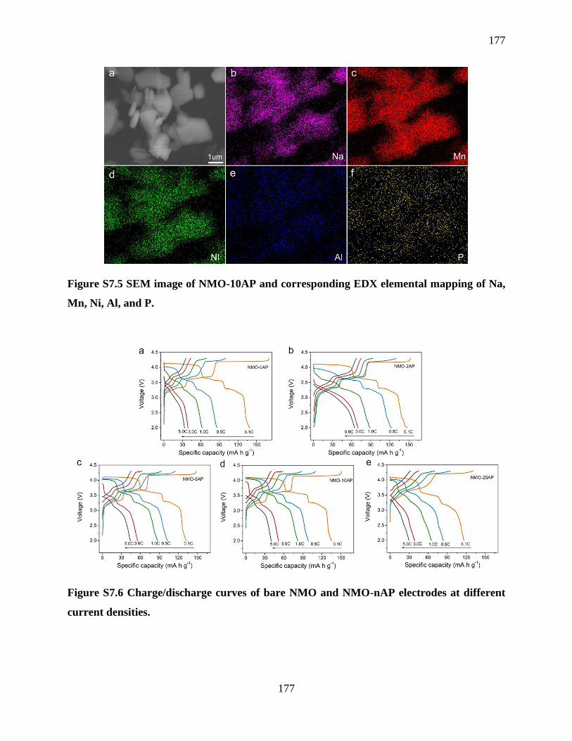
177
177
Figure S7.5 SEM image of NMO-10AP and corresponding EDX elemental mapping of Na,
Mn, Ni, Al, and P.
Figure S7.6 Charge/discharge curves of bare NMO and NMO-nAP electrodes at different
current densities.

178
178
Figure S7.7 a) Initial cycle charge/discharge curves; b) 200th cycle charge/discharge curves
of the bare NMO and NMO-nAP electrodes.
Figure S7.8 Capacity retention comparisons between bare NMO and AP coated NMO
electrodes over 50 cycles at 0.5C and 200 cycles at 2.0C.
Table S7.1. Rs value of bare NMO and AP coated NMO electrodes after 10 cycles and 50
cycles.
Electrode Rs (Ω) after 10 cycles Rs (Ω) after 50 cycles
Bare NMO 336.1 485.9
AP coated NMO 218.5 257.6

179
179
Chapter 8
8 Summary and Future Work
8.1 Conclusions
Rechargeable batteries have attracted significant attention due to their high energy density and
power density as well as pollution-free operation. However, traditional manufacturing methods are
hard to fabricate thick electrodes with fast electron/ion transport due to the planar structure
limitations. Moreover, electrodes and electrolytes fabricated by traditional techniques have limited
form factors and mechanical flexibility. Extrusion-type 3D printing techniques thus have been
applied to design various 3D architectures for achieving high-performance Li/Na batteries.
In chapter 3, 3D patterned self-supported thick LFP electrodes for high areal energy and power
density LIBs were realized by an optimized extrusion-type 3D printing technique. The resulting
unique 3D structured electrodes were constructed by continuous layer-by-layer filaments
composed of interconnected porous polymer frameworks and continuous conducting carbon
networks, thereby greatly improving ion and electron transport. The well-designed 3D micro-
structures were demonstrated to increase the surface area and maintain a short ion transport
distance even within a thick electrode, facilitating the electrolyte penetration into the active
materials as well as ion/electron diffusion. Due to these structural merits, the 3D-patterned
electrodes exhibited superior electrochemical performance over conventional thick flat electrodes
in terms of specific capacity and cycling stability. Moreover, an ultrathick LFP electrode of 1500
µm 3D electrodes with 8 printed layers was fabricated and presented a high areal capacity of
approximately 7.5 mA h cm-2 and energy density of 69.41 J cm-2 at a power density of 2.99 mW
cm-2, demonstrating comparable values with reported high-performance LFP cathodes fabricated
by both 3D printing and other methods in literature. This work thus provides a facile, low cost,
and easily scaled way to fabricate high areal loading/thick electrode to achieve high areal energy
density with high power density, which holds great promise for future practical application of high
energy density lithium-ion batteries.
In chapter 4, a novel facile 3D printing approach was developed to rapidly construct patterned Si
electrodes with vertically aligned and multi-scaled porous structures to achieve high areal capacity
180
180
LIBs. Compared to the conventional flat 2D Si electrodes, the 3D-printed Si electrodes possessed
vertically aligned mass/ionic transport pathways and macro/micro-scaled porosities, which helped
facilitate the electron/ion transport within the whole electrodes and effectively helped mitigate the
large volume expansion during cycling by providing extra negative space. From the structural
advantages, the 3D-printed Si was able to exhibit a superior areal capacity of around 3 mAh cm-2
(corresponding to a specific capacity of 1450 mAh g-1) after 60 cycles. Moreover, the 3D-printed
Si delivered excellent performance merits under different areal mass loadings. Even under a high
mass loading of 3.81 mg cm-2, the 3D-printed Si displayed an extremely high areal capacity of
10.31 mAh cm-2 (2706.04 mAh g-1). This work demonstrated a facile 3D printing approach to
design unique architecture for realizing a high-performance Si anode. These techniques hence open
a promising avenue for developing other advanced energy systems in the future.
In chapter 5, We have developed a low-cost aqueous-based printable ink for fabricating uniform
LAGP thin films via an advanced extrusion-type 3D printing approach. Compared with the
conventional pressed thick LAGP pellets, the printed thin LAGP can not only reduce the total
weight of a cell but also shorten the Li+ transport distance, which could increase the energy density
and power density of a solid battery. Benefiting from these merits, a LiFePO4(LFP)/Li solid battery
with the printed LAGP thin film as the electrolyte delivers a superior specific capacity of around
130 mAh g-1 even at a high rate of 5C, which is much higher than that of the battery with a thick
LAGP pellet (1mm) fabricated by conventional cold-sintering technique. This method offers the
flexibility of fabricating thin solid-state electrolytes with controllable thickness in a low-cost and
efficient way. In addition, various patterned LAGP architectures are easily fabricated, broadening
the diversity of solid batteries with various size and shapes. This work thus would shed light on
fabricating desirable solid-state electrolytes for next-generation high-energy-density solid-state
batteries.
In chapter 6, an extrusion-type 3D printing approach was first developed to construct a high-
performance SMB which was assembled by a printed Na@rGO/CNT anode and a printed NCNFM
cathode. The 3D-printed Na@rGO/CNT anode possesses multiple porosities, which could provide
abundant active reaction sites and enable fast Na+ transport. Moreover, the resultant 3D structured
Na@rGO/CNT can effectively suppress the Na dendrite growth by decreasing the local current

181
181
density and releasing the huge volume change of Na during cycling. As a result, the printed
Na@rGO/CNT composite can deliver extremely stable performance over 2000 h (~1000 cycles)
at a current density of 1 mA cm-2. Even with a high capacity of 3mAh cm-2, the Na@rGO/CNT
composite can still exhibit a long cycle life of 300 h at a current density of 3 mA cm-2, which is
almost three times higher than that of the bare Na foil. On the other hand, the 3D-printed micro-
structured NNCFM cathode composed of interconnected CNTs and porous polymer framework
can enable fast electron and ion transport as well as facilitated electrolyte penetration within the
whole electrode. This work thus offers a promising approach to construct high-performance Na-
metal batteries, which can also be extended to develop next-generation high energy density Na-S
and Na-O2 batteries.
In order to further increase the energy density of a SIB, chapter 7 demonstrated the developing of
high-voltage layered P2-Na2/3Ni1/3Mn2/3O2 (NMO) cathodes. We further apply an
electrochemically stable nanoscale surface coating of AlPO4 on the NMO cathode with
controllable thickness via atomic layer deposition (ALD). The effect of coating thickness on the
electrochemical performances was systematically studied. The results show that ALD AlPO4-
coated NMO electrodes exhibit superior cycling stability and enhanced rate capabilities. The
electronic structure of the system was examined using X-ray Absorption Near-Edge Structure
(XANES). The XANES results revealed that the AlPO4 coating layer could suppress the reduction
of Mn upon cycling, which could help improve the structural stability of the cathode.
8.2 Future Work
This thesis has successfully developed various printable inks and designed unique 3D micro-
structures via an advanced extrusion-type 3D printing technique for energy storage applications.
3D printing has shown great advantages in fabricating Li/Na battery electrodes and solid-state
electrolytes. Future research can be directed to the developing of novel battery component inks
and new battery forms.
This thesis first presents the fabrication of 3D-patterned self-supported thick LiFePO4 via an
extrusion-type 3D printing approach. The designed unique 3D architectures could improve the
electron/ion transport within the electrode as discussed in chapter 3. However, it is known that

182
182
LiFePO4 has a low working plateau of around 3.4 V and a relatively low theoretical capacity of
170 mAh g-1, resulting in a limited energy density. Therefore, promising cathodes with high
capacity and high voltage plateau, such as LiCoO2, LiNi0.8Mn0.1Co0.1O2, and LiNi0.5Mn1.5O4, can
be adopted for developing high-energy-density LIBs.
Chapter 4 describes the employing 3D printing approach for designing patterned Si anodes with
vertically aligned and multi-scaled porous structures in order to achieve high-areal capacity LIBs.
Although high areal capacity can be obtained, the long-term cycling performance still needs to be
further improved. In this case, further work can be focused on developing 3D-patterned
graphene/Si electrodes by using the extrusion-type 3D printing method, since graphene could
greatly enhance the conductivity of the electrode while the designed 3D structures can effectively
mitigate the huge volume expansion of Si during cycling processes. Moreover, the combination of
3D-printed Si anodes with printed high-capacity and high voltage cathodes should be investigated
to realize a printed high-performance full battery.
In chapter 5, we demonstrate the fabrication of LAGP solid electrolytes via the 3D printing method.
The printed solid electrolyte has a thickness of around 100 µm, which can significantly shorten the
Li+ transport path when applied in a solid battery. In the future, complex 3D structured solid
electrolytes can be developed to construct 3D solid-state batteries. For instance, a dense-porous
solid-state electrolyte framework can be fabricated by the 3D printing approach. In this unique
structure, the porous part can be acted as a host for cathode materials, while the thin dense layer
can separate the cathode and the anode. This dense-porous structure can considerably increase the
loading of cathode materials, thus improving the energy density of a solid battery.
In chapter 6, we fabricate self-supported 3D structured Na@rGO/CNT composite anodes and O3-
NaCu1/9Ni2/9Fe3/9Mn3/9O2 (denoted as NCNFM) cathodes using the layer-by-layer extrusion-type
3D printing approach for high-energy-density SMBs. The resultant 3D structured Na composite
can effectively suppress the Na dendrite growth by decreasing the local current density and
releasing the volume change during the sodiation/desodiation process. In the future, we can
develop high capacity cathodes, such as sulfur cathodes and air-based cathodes, for realizing all-
printed Na-S and Na-O2 batteries.

183
183
To further increase the energy density of a sodium-ion battery, we developed high-voltage layered
P2-Na2/3Ni1/3Mn2/3O2 (NMO) cathodes in chapter 7. By applying ALD AlPO4 coating layer on the
NMO particles, the reduction of Mn was suppressed upon cycling, which could improve the
structural stability of the cathode. Future work can be focused on 3D printing of high-voltage
sodium layered cathodes and combining them with ALD techniques for achieving long-term high-
areal capacity sodium cathodes.

184
184
Appendices
Appendix: PERMISSION FROM AMERICAN SOCIETY OF CHEMISTRY
185
185
Curriculum Vitae
Name: Jiwei Wang
Post-secondary The University of Western Ontario
Education and London, Ontario, Canada
Degrees: 2015-present Ph. D. Candidate
Soochow University
Suzhou, Jiangsu, China
2012-2015 M.S.
East China University of Science and Technology
Shanghai, China
2008-2012, B. Eng
Related Work Teaching Assistant in Chemistry
Experience The University of Western Ontario
2016-2019
Publications:
1. J. Wang, Q. Sun, X. Gao, C. Wang, W. Li, F. Benjamin. M. Zheng, T. Sham*, and X. Sun*.
Toward High Areal Energy and Power Density Electrode for Li-Ion Batteries via Optimizing 3D
Printing Approach. ACS Appl. Mater. Interfaces, 2018, 10, 39794-39801.
2. J. Wang, T. Sham, and X. Sun. 3D Printing of Vertically Aligned and Patternable Silicon
Anodes for High Areal Capacity Li-Ion Batteries. (To be submitted)
3. J. Wang, and X. Sun. 3D Printing of Shape-Versatile and Thin Solid Electrolyte for High-
Performance Solid-State Li-Metal Batteries. (To be Submitted)
186
186
4. J. Wang, and X. Sun. 3D Printing of High-performance Sodium Metal Batteries. (To be
Submitted)
5. J. Wang, T. Sham, and X. Sun. Nanoscale Surface Modification of High-Voltage Layered
Sodium Cathode via Atomic Layer Deposition of Aluminum Phosphate with Enhanced Cycle
Performance. (To be Submitted)
6. Y. Sun, Y. Zhao, J. Wang, J. Liang, C. Wang, Q. Sun, X. Lin, K. Adair, T. Sham, and X. Sun*.
A Novel Organic “Polyurea” Thin Film for Ultralong-Life Lithium-Metal Anodes via Molecular-
Layer Deposition. Adv. Mater., 2019, 31, 1806541.
7. X. Gao, Q. Sun, X. Yang, J. Liang, A. Koo, J. Wang, F. Benjamin, T. Sham, and X. Sun.
Toward A Remarkable Li-S Battery via 3D Printing. Nano Energy, 2019, 56, 595-603.
8. Y. Zhao, J. Liang, Q. Sun, L. Goncharova, J. Wang, C. Wang, K. Adair, X. Li, F. Zhao, Y. Sun,
R. Li, and X. Sun. In Situ Formation of Highly Controllable and Stable Na3PS4 as A Protective
Layer for Na Metal Anode. J. Mater. Chem. A, 2019, 7, 4119-4125.
9. C. Wang, K. Adair, J. Liang, X. Li, Y. Sun, X. Li, J. Wang, Q. Sun, F. Zhao, X. Lin, R. Li, H.
Huang, and X. Sun. Solid-State Plastic Crystal Electrolytes: Effective Protection Interlayers for
Sulfide-based All-Solid-State Lithium Metal Batteries. Adv. Funct. Mater., 2019, 1900392.
10. X. Gao, X. Yang, M. Li, Q. Sun, J. Liang, J. Luo, J. Wang, W. Li, J. Liang, Y. Liu, S. Wang,
Y, Hu, T. Sham, X. Sun. Cobalt-doped SnS2 with Dual Active Centers of Synergistic Absorption-
Catalysis Effect for High-S Loading Li-S Batteries. Adv. Funct. Mater., 2019, 1806724.
11. X. Gao, X. Yang, Q. Sun, J. Luo, J. Liang, W. Li, J. Wang, S. Wang, M. Li, R. Li, T. Sham,
and X. Sun. Converting a Thick Electrode into Vertically Aligned “Thin Electrodes” by 3D-
Printing for Designing Thickness Independent Li-S Cathode. Energy Storage Mater., 2019

187
187
Conference Presentations:
J. Wang, T. K. Sham, and X. Sun et al. (Oral) Nanoscale Surface Modification of High-Voltage
Layered Sodium Cathode via Atomic Layer Deposition of AlPO4 with Enhanced Cycle
Performance. The 102nd Canadian Chemistry Conference and Exhibition (CCCE 2019), 2019,
Quebec, Canada