Embed Size (px)
Citation preview

Extrusion I Cast & Blow Film Lines I Quality ControlR & D, QC, Lab & on-line application
The solution for the polymer & petrochemical industries
The original by OCS

The measuring extruder of the type ME is intended
for the production of narrow films for laboratory
and small-batch production. The optimum simu-
lation of the production process is ensured be-
cause of the flexibility and the modular concept.
The same results achieved in the laboratory and
on production extruders are a major contribution
to quality assurance.
All components are integrated in a sturdy steel
frame which is height adjustable. The control
elements are ergonomically arranged at the
operator‘s level in a swivel-type control panel. This
ensures that the extrusion parameters set are
always in view.
In environments where no permanent staff are
employed, the optional remote control unit offers
an ideal solution for monitoring and controlling the
unit from a distance. In addition all parameters
are stored in a protocol file which permits later
analysis at any time.
When connected to a chill roll and winding system
CR 9/WU9, the extruder creates a self-contained
basis for connecting optical measuring equipment.
Furthermore, the modular concept permits the
use of different optional accessories which always
ensures an easy and convenient adaptation.
Measuring Extruder Type ME
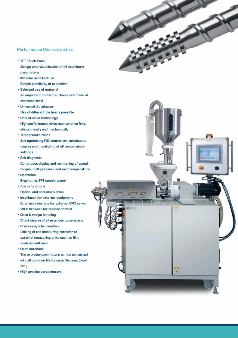
Performance Characteristics
• TFT Touch Panel
Design with visualisation of all machinery
parameters
• Modular architecture
Simple possibility of expansion
• Selected use of material
All important contact surfaces are made of
stainless steel
• Universal die adapter
Use of different die heads possible
• Robust drive technology
High-performance drive maintenance free,
electronically and mechanically
• Temperature zones
Self-optimising PID controllers, continuous
display and monitoring of all temperature
settings
• Self-diagnosis
Continuous display and monitoring of speed,
torque, melt pressure and melt temperature
• Operation
Ergonomic, TFT control panel
• Alarm functions
Optical and acoustic alarms
• Interfaces for external equipment
Ethernet interface for external OPC server
WEB browser for remote control
• Data & recipe handling
Chart display of all extruder parameters
• Process synchronisation
Linking of the measuring extruder to
external measuring units such as film
analyzer software
• Open database
The extruder parameters can be converted
into all common file formats (Access, Excel,
etc.)
• High precise servo motors

• Device interface
Ethernet 10/100 M Base T
• Physical interfaces (datex per external server)
Ethernet 10/100/1000 M Base T,
USB, RS 485, RS 232, digital & analogue I/0
• Communication protocol
(datex per external server)
MODBUS RTU, MODBUS TCP/IP, OPC, SQL,
Filetransfer, PROFIBUS
Implementation to other Fieldbus-Systems
possible
•Power supply
400 V, 3 phase + N + PE (5 wires)
• Weight
Approx. 350 kg
• Temperature
15 - 40 °C
• Tool kit
For maintenance and cleaning work
Technical alterations are subject to change
without prior notice
Technical Data
• Drive technology
Synchronous motors
2.8 kW, 5.8 kW, 9.1 kW
Speed range 0.2 - 150 rpm
Max. torque 120, 300, 500 Nm
• Screw (individual configuration)
Special steel, ionitrided
Single-thread
Feed zone
Compression zone
Metering zone
Compression ratio
Mixing part
Barrel Diameter 20, 25, 30 mm
[others on request]
Length 10D - 35D
[standard 25D, optional 10 - 35D]
Wide range of screw design
• Temperature zones
Setting range 0 - 400 °C
Temperature sensors type FeCuNi, type J
Max. working temperature 380 °C

Chill Roll & Winder Unit CR9/WU9
The Chill Roll & Winder Unit has been specially
developed to meet the requirements of the polymer
raw material producers.
The CR9/WU9 can contain an FTIR for on-
line spectroscopy, haze- gloss- and thickness
measurement and it can be used in the labora-
tory or online. The system consists of two chill rolls
with controlled drive, several guidance rolls, haul-off
station with two rubber-nip rolls followed by acen-
tral pneumatically expandable winder. The winder
and nip roll are regulated via the tension control.
In addition the CR9/WR9 is endued with TFT
touch control panel for improving the visualisation
of user and equipment parameters, a digital and
manual rotation adjustment, film tension control
and speed control. A speed indication for chill rolls
and nip rolls is available and the winder is pneuma-
tically expandable.
The CR9/WU9 are equipped with a film break
sensor and a detector for film direction as an
alarm function. An electrostatic discharging of
the winder with ionised air is available.

Performance Characteristics
• Modular architecture
Simple possibility of expansion, easy
adaptation
• Safety clutch for all drive
Guarantees safe handling and protects
for injuries
• Exchangeable chill roll sleeve
Simplifies the maintenance and
reduces costs
• Option of following devices
FTIR spectrometer, TM9 (thickness measure-
ment), Gamma 12 (haze measurement),
GM5 (gloss measurement)
• Self-diagnosis
Constant display and monitoring of chill roll
speed, tensile force setting and winder
status
• Robust drive technology
The high-performance drives are monitored
electronically and mechanically
• Interfaces
Ethernet interface for external OPC server
WEB browser for remote control
• Operation
Ergonomic, swivel-type control panel
• Alarm functions
Optical and acoustic alarms
• Mobility
Units are movable to assure convenient
handling and maintenances
• Use of selected material
All important contact surfaces are made of
stainless steel
• High precise servo motors
• Interfaces for external equipment
ACS remote control, PROFIBUS, RS485
Chill roll sleeve exchangeable
for easy maintenance

Technical Data
• Drive technology
Three asynchronous drive units
with servo controllers
Rating: 0.25 kW
Production speed: up to 15 m/min
[optional 30 m/min]
• Chill rolls
Diameter: 140 mm
Width: 200 mm or 320 mm
Working width: 160 mm or 300 mm
Material: stainless steel chromium-plated or
anti-stick coating
Temp. ranges: 5 - 85 °C (optional up to 150 °C)
• Guide rolls
Diameter: 40 mm
Working width: 160 mm or 300 mm
Material: stainless steel
(optional Coating-K coating)
• Nip rolls
Diameter: 90 mm
Working width: 160 mm or 300 mm
Tension force: max. 20 N
Material: aluminium rubber-coated
• Winder
Shaft: 150 mm
Film roll diameter: up to 600 mm
Working with: 160 mm or 300 mm
• Tension force: max. 20 N
• Device interface
Ethernet 10/100 M Base T
• Physical interfaces (datex per external server)
Ethernet 10/100/1000 M Base T,
USB, RS 485, RS 232, digital & analogue I/0
• Communication protocol
(datex per external server)
MODBUS RTU, MODBUS TCP/IP, OPC,
SQL, Filetransfer, PROFIBUS
Implementation to other
Fieldbus-Systems possible
• Power supply
400 V, 3 phase + N + PE (5 wires)
• Size dimension
CR9: (l, w, h) 165 x 118 x 186 cm
Working height 110 cm
Weight approx. 360 kg
FTIR: (l, w, h) 264 x 126 x 186 cm
Weight approx. 700 kg
CR9/G: (l, w, h) 193 x 120 x 186 cm
Weight approx. 440 kg
Technical alterations are subject to change
without prior notice

Remote Control Function
LYONDELLBASELL
BAYER
SABIC
BOROUGE/BOREALIS
DOW
INEOSEXXONMOBIL

Cast Film Lines
They are used to produce high-quality flat film to
carry out optical and physical measurements, all
settings and parameters, e.g. extruder speed,
temperature, film tension, winding force, winder
diameter, etc. are stored by a touch panel control
system, which guarantees, that the film quality
can be reproduced at any time- an important
parameter for optical & physical on-/off-line meas-
urements, for example detecting gels, contamina-
tions, degradations and other impurities as well
as haze, gloss, density and additive measurement.
The cast film line consists of:
• Extruder with a diameter of 20, 25 or 30 mm,
length 10D - 35D
• Cast film die with a width of 20, 50, 100, 150,
300 mm, fix or flexible gap
• Chill Roll & Winding system
• Other sizes for extruders and dies are available
on request

The blow film lines are used to produce high-quality
blown films to carry out optical and physical
measurements, all parameters of the system, e.g.
extruder speed, temperature, haul-off speed, film
width, film bubble ratio, etc. are stored at the touch
panel control system, which guarantees, the
reproducibility of the film quality at any time- as the
frost line can be kept in the same position, this is an
important parameter for optical & physical on-/
off-line measurements, for example detecting gels,
contaminations, fibres and other impurities as well
as haze, gloss, density and additive measurement.
An optical device measures the width of the
flattened film and controls the diameter of the film
bubble. In this way, the desired film width is record-
ed. The tower height is electrically driven, freely
adjustable and can therefore be set optimally for
any extruded materials.
The take-off nip rolls are driven pneumatically and
their temperature is optionally controlled.
The film bubble can be stabilised with additional
guiding rolls, adjustable wooden grids and Teflon-
coated rolls lead the film bubble into a flat layer
film, some guiding rolls are specially designed to
prevent wrinkles.
The complete operation is visualised on the touch
screen.
The blow film line consists of:
• Extruder with a diameter of 20, 25 or 30 mm
• Blow film die with a diameter
30/50/75 mm
• Haul-off tower and winding system
• Other sizes for extruders and dies are available
on request
Blow Film Lines

Performance Characteristics
• Cooling ring with large sized air distribution
chamber
• Labyrinth styled for air flow and uniform
pressure
• Adjustable cooling ring gap
• The tower is electrically driven
• Automatic bubble diameter control
according to the set ratio
• Electronic width measurement of the
flattened film
• Pneumatic drive for rubber and
chrome nip rolls
• Automatic nip rolls open/close
• Spiral (mandrel) melt distributor including
three heating zones
Technical Data
• Die diameter 30/50/75 mm
• Die gap 0,5/0,8/1,2 mm
• 8 channel melt distribution
• Blown-up film diameter max. 180/240 mm
• Flattened film width max. 280/380 mm
• Haul-off speed 0 - 15 m/min
(optional 30 m/min)
• Haul-off force 0 - 20 N
• Total height 220 - 320 cm
• Power supply
400 V, 3 phase + N + PE (5 wires)
• Weight
Approx. 500 kg
Technical alterations are subject to change
without prior notice

The Pelletizer is used to change the quality
characteristics, different formulations such as
additives matrixes and master batch compounds,
sizes/shapes for R&D as well as recycling studies
of polymers.
After compounding and mixing the new material
with the base material in the extruder, a strand
passes through a water bath for cooling, air blower
for drying and finally into the pelletizer to produce
pellets with the new properties.
A complete lab scale strand solution with a Pellet-
izer enfolded: Extruder, strands die, water bath
and strand pelletizer with adjustable speed.
The pelletizer system consists of:
• Extruder with 20, 25 or 30 mm diameter
depending on the requirement
• Screw with option of different compression
ratios and mixing zones
• Strand die plate with 1 or 2 outputs and a
diameter of 3, 4, 5 mm, etc.
• Stainless steel water bath with air blower die
• Pelletizer unit with adjustable speed and pellet
collector
Pelletizer
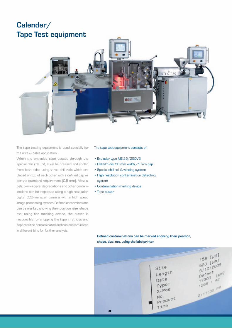
Calender/Tape Test equipment
The tape testing equipment is used specially for
the wire & cable application.
When the extruded tape passes through the
special chill roll unit, it will be pressed and cooled
from both sides using three chill rolls which are
placed on top of each other with a defined gap as
per the standard requirement (0,5 mm). Metals,
gels, black specs, degradations and other contam-
inations can be inspected using a high resolution
digital CCD-line scan camera with a high speed
image processing system. Defined contaminations
can be marked showing their position, size, shape
etc. using the marking device, the cutter is
responsible for chopping the tape in stripes and
separate the contaminated and non-contaminated
in different bins for further analysis.
The tape test equipment consists of:
• Extruder type ME 25/25DV3
• Flat film die, 50 mm width /1 mm gap
• Special chill roll & winding system
• High resolution contamination detecting
system
• Contamination marking device
• Tape cutter
Defined contaminations can be marked showing their position,
shape, size, etc. using the labelprinter

Performance Characteristics
• Touch screen controlled
• Back-geared servomotor driven chill rolls
• Height adjustable (customised)
• Manual calender interlock
• Manual adjusting film thickness
• Film break sensor (optional)
• Exchangeable chill roll sleeve
Simplifies the maintenance and
reduces costs
Film-Test-Line with an edge-slitter-winder (optional)

Technical Data
• Drive technology
Three asynchronous drive units
with servo controllers
Production speed: up to 10 m/min
• Gap size adjusting 0,3 - 1 mm
• Chill/Calender rolls
Diameter: 140 mm
Width: 130 mm
Working width: 100 mm
Material: stainless steel, chromium-plated or
anti-stick coating
Temperature: 5 - 85 °C
(optional up to 150 °C)
• Nip rolls
Diameter: 90 mm
Width: 160 mm
Working width: 100 mm
Tension force: max. 20 N
Material: rubber coated
• Guide rolls
Diameter: 40 mm
Width: 190 mm
Material: stainless steel
• Winder
Shaft diameter: 150 mm (optional 100 mm)
Film roll diameter: up to 600 mm
Edge-slitter-winder [optional]
• Cutter module
Working width: up to 100 mm
Material thickness: max. 0,3 - 0,7 mm
• Device interface
Ethernet 10/100 M Base T
• Physical interfaces (datex per external server)
Ethernet 10/100/1000 M Base T, USB,
RS 485, RS 232, digital & analogue I/0
• Communication protocol
(datex per external server)
MODBUS RTU, MODBUS TCP/IP, OPC,
SQL, Filetransfer, PROFIBUS
Implementation to other
Fieldbus-Systems possible
• Weight
Approx. 510 kg
• Power supply
400 V, 3 phase + N + PE (5 wires)
• Temperature 15 - 40 °C
Technical alterations are subject to change
without prior notice

Filter Test ME FT20, ME FT25
The Filter Test System works according to the
standard DIN EN 13900-5 to determine the Filter
Pressure Value (FPV).
The system consists of a 20, 25 or 30 mm ex-
truder, a screen changer which can receive differ-
ent filter packages with different sizes, a strand
die and optionally a gear pump for more constant
melt feeding. The screen pressure test serves
to recognize quality differences in a polymer. The
screen pressure test can be used, for example:
• In the field of product development to optimize
the colour approach
• In the field of quality control
The measurement principle of the FPV is to
measure the pressure increase before the screen
filter by time. This is an indication of the melt purity.
Following operations are possible:
• The extruder is feeding the screen changer
directly with the melt
• The extruder works with constant rotation
without gear pumps
• Pressure monitoring before the sieve package
and automatic determination of the pressure
increase by time
• The extruder is feeding a gear pump with
constant pressure and the gear pump is
feeding the screen changer
• The extruder with constant pressure before
the gear pump and gear pump work with
constant rotation
• Continuous monitoring and full automatic
measurement to determine the Filter
Pressure Volume (FPV)
The material to be tested is molten and homo-
genized in an extruder and is delivered via a melt
pump with a defined and constant volume flow to
the filter. Particles of a certain size clog the filter
and so reduce the free penetration surface of the
screen. Consequently, with a constant volume flow
in front of the screen, the pressure does increase
and is recorded by a sensor and can be used to
define the quality of the material tested.
By using a by-pass valve, the melt flow can be by-
passed in front of the screen. This enables an
interruption of the melt flow without having to
stop the extruder or the melt pump. A change of
the screen can easily be done while purging both,
the extruder and melt pump.
For standard measuring in the field of master
batch, small batches are used. The extruder’s
base group includes the electrical control for
extruders and melt pump. The screen measuring
equipment is a movable part of the extruder to
unlock and clean the screw easily.
All results are calculated and displayed directly on
the TFT touch panel beside all extrusion parameters.

Optionally a strand die, stainless steel water bath
and pelletizer unit can be combined with the Filter
Test System to achieve additional configuration.
For testing larger batches of polymers which need
a larger throughput, a larger size extruder with a
diameter of (25 mm or 30 mm) can be used. This
combination allows throughputs from 1 to 10 kg/h.
Herewith, all requirements for testing polymers
or compounds are fulfilled.
Technical Data
• Barrel
20, 25, 30 mm diameter, length 25D
3 heating zones with thermocouples
for barrel
4 additional heating zones for melt pump
and adapter
3 cooling zones with low pressure blower
• Screw: 3 zone, compression 3:1
• RPM: 0 - 150 rotation/min
• Torque: 120 Nm, 300 Nm, 500 Nm
• Drive technology
Synchronised servo-motor
2,8 kW, 5,8 kW, 9,1 kW
• Temperature control with drive stop
• Automatic temperature decrease in
alarm situation
• LCD Touch Panel
• User and system configurations can be
saved or loaded
• Pressure measurement
• Melt temperature measurement
• Automatic alarm handling
• Interfaces
Web browser interface
OPC Interface (optional)
• Remote control capability
• Power supply
400 V, 3 phase + N + PE (5 wires)
220 V plug for follow up equipments
Technical alterations are subject to change
without prior notice


• Improvement of quality
(elimination of non-standard products)
• Competitiveness by QC-Automation
• Accurate and consistent automatic grading
• Reduction of customer returns and
complaints
• Increased line speed and process throughput
where manual inspection is a limiting factor –
perfect for online and laboratory applications
• Efficient, objective and reproducible
laboratory evaluation
• Optimised quality
• Increased competitiveness by automated
quality control
• Precise and consistent quality evaluation
• Faster inspection
Suitable for Research & Development,
laboratory use and for statistical production
control
• Reproducible operation settings
• Precise control of haul-off and winding
motors
• Full automatic control of haul-off and
winding tension
• Maintenance free
• Designed for 24/7 continuous operation
Your advantages
ARKEMA
ARYA SASOL
LYONDELLBASELL
BASF
BAYER
SABIC
BOROUGE/BOREALIS
BRASKEM
CHINA PETROCHEMICAL
PETROCHINA
CABOT
CLARIANT
DOW
DSM
DUPONT
EXXONMOBIL
GE PLASTICS
INEOS
JAPAN POLYETHYLENE
MITSUBISHI
MITSUI
NEXANS INDIAN OIL
NOVA
QAPCO
REPSOL
RÖHM & HAAS
SOLVAY
TETRA PAK
TOTAL

Optical Control Systems GmbHWullener Feld 2458454 Witten
Germany
Fon +49 (2302) 95 622 – 0Fax +49 (2302) 95 622 – 33