Embed Size (px)
Citation preview

EZ-SCREEN® LPwith Integral Muting

Introduction
■ No “third box” muting controller required
– Simple design & lower installed cost
■ Many of the same features as a standard EZS Low Profile (e.g. Scan codes, Reduced Resolution, Fixed Blanking)
– No cascading, No 270 mm model
■ Same list prices as Cascade Receivers
– $72 adder from standard EZS LP
– Uses standard EZS LP emitters

Muting Configurations
Seven Pre-Defined Muting Configurations
■ Maximum Mute Cycle Time (Infinite or 60 sec)
■ Bypass or Mute Dependent Override
■ Mute Enable options
■ “L” configuration Exit Application (option #7)

Muting Configurations, cont.
■ Bypass: Force the OSSDs to turn ON or stay ON at anytime (other than during a lockout)
■ Mute Dependent Override: The defined area must be blocked and one or both Mute Inputs must be active to start the override (turn ON the OSSDs)

Muting Configurations, cont.
■ Mute Enable selection allows for “Directional” or “One-way” muting
– Requires an additional device to “window” when a mute can begin

Muting Configurations, cont.
“L” Configuration Exit Application
■ “Holds” mute ON for 4 seconds
■ Both sensors on thehazardous side
■ Another means of Directional/One-way muting

Configuration and Indicators
■ Configured via DIP-switches
– Similar steps as configuring a cascade system
– T, RR off, L, RR on and then toggle “invert” switch
– Configuration number displayed
– No PC or hand-held device
■ Easy to see Status, Reset, Zone, Mute Device and Diagnostic indicators and displays
– M1 and M2 Mute Input indicators

Receiver Inputs and Outputs
■ Normally open Reset / Override1 Input.
■ Normally closed Override2 / Mute Enable Input
■ 1-Channel External Device Monitoring (EDM)
■ 2x Mute Device Inputs (PNP or Normally Open contacts)
■ 2x OSSDs, +24Vdc / 500 mA each
■ AUX Output, +24Vdc / 250 mA (OSSD-follow / Fault)
■ Mute Lamp and status outputs (at the “top” end)
– Mimics receiver indicators

Mute Cycle Indicators
■ Mute Lamp & Status Outputs
– Mounting bracket & DELPEF cordset
■ EZ-LIGHT® indicators
– Standard 1-color
– TL50GYRWQ
• 4-color Tower
– K50LGRW2PQ-18886
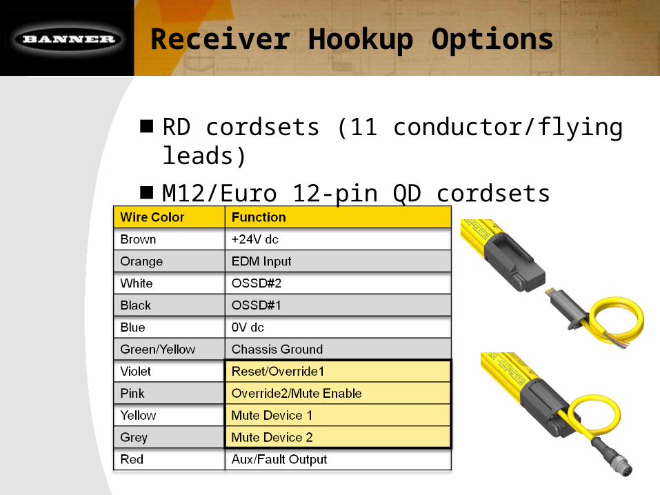
Receiver Hookup Options
■ RD cordsets (11 conductor/flying leads)
■ M12/Euro 12-pin QD cordsets

Receiver Hookup Options, cont.
■ CSMxxx Muting Splitter QD Cordsets
– M1 and M2 mute sensor inputs
– Dark and Light Operate models
– Three branch to connect sensors and receiver
– Four branch to connect “P8” emitter
– Use with “P12” receiversor DELPE-12xE cordset

Application Example #1
“X” – Pattern Entry/Exit
■ Excellent solution

Application Example #2
Entry/Exit Application using four pairs of sensors
■ Parallel M1 & M4 (Input #1) and M2 & M3 (Input #2)

Application Example #3
“L” Configuration Exit Application
■ Mute-cycle time extension (4 seconds)

Application Example #4
Robot Operator Load/Unload

Summary
■ “EZ” setup and installation
■ Built-in muting function, no third box required
■ Seven muting configurations
– E.g. “L” configuration Exit Application
■ Mute Lamp and Status Outputs to EZ-LIGHT
■ 1-Ch External Device Monitoring
■ DIP switch configurable; No PC orHand-held device
■ Many of the same features as a standard EZS LP
■ 14 or 25 mm resolution, 410 to 1810 mm defined areas


![Operating Instructions Flexi Classic Muting Modular Safety Controller en IM0026926[1]](https://img.pdfslide.net/doc/110x75/577c837f1a28abe054b53102/operating-instructions-flexi-classic-muting-modular-safety-controller-en-im00269261.jpg)
