Embed Size (px)
Citation preview
FAN
COO
L1
COO
L2
HEAT1
HEAT2
BYPASSO
PEN
BYPASSCLO
SE
COM
MUNIC
ATION
ALARM
A=
ALLZO
NES
B=
EACHZO
NE
C=
HVACUNIT
/CLEAR
D=
ALARMS
#=
STEP/ENTER
* =DECIM
AL
+
+
+
+
Meridian
COOL
MODE
04-08-96
03:48PMFRI
OCCUPIED
NOALARMS
2
8
5
0
A
C
B
D
1
7
4
*
3
9
6
#
YO
RK
Clear Window
Area
6
5
4
DEC
7MIN
US
0
CLEAR9
8
1
3
2
MENU
Overr
ide
Com
munic
ation
ENTER
ESC
Ala
rmSystem
Manager
-
Merid
ianPlus
05/17/0
003:3
8PMW
ED
OCCUPIED
NOALARM
S
Heating and Air Conditio
ning
®
FAN
COO
L1
COO
L2
HEAT1
HEAT2
BYPASSO
PEN
BYPASSCLO
SE
COM
MUNIC
ATION
ALARM
A=
ALLZO
NES
B=
EACHZO
NE
C=
HVACUNIT
/CLEAR
D=
ALARMS
#=
STEP/ENTER
* =DECIM
AL
+
+
+
+
Meridian
COOL
MODE
04-08-96
03:48PMFRI
OCCUPIED
NOALARMS
2
8
5
0
A
C
B
D
1
7
4
*
3
9
6
#
YO
RK
EZ ZoneEZ ZoneEZ ZoneEZ ZoneEZ Zone
TTTTTooooo
UpgUpgUpgUpgUpgrrrrradeadeadeadeade
GuideGuideGuideGuideGuide
036-21423-001 Rev. A (0602)

EZ Zone/Meridian
2 Upgrade
036-21423-001 Rev. A (0602)
Form: 036-21423-001 Rev. A (0602) Supersedes: NothingCopyright 2002 York International Corp..
Meridian is a registered trademarkof York International Corp.York International Corp. assumes no responsibility for errors, or omissions.
This document is subject to change without notice.All rights reserved.
EZ Zone/Meridian
Upgrade 3
036-21423-001 Rev. A (0602)
Table of Contents
Introduction ........................................................................................................................................ 4EZ Zone Upgrade Overview .............................................................................................................. 5Component Descriptions .................................................................................................................... 6Upgrade Package Selection ................................................................................................................ 7Example #1 - EZ Zone Stand Alone To Meridian Basic .......................................................... 8 & 9Example #2 - EZ Zone Stand Alone To Meridian Plus ........................................................ 10 & 11Example #3 - Networked EZ Zone To Meridian Plus .......................................................... 12 & 13Optional Controllers And Accessories ................................................................................... 14 & 15EZ Zone Wiring ................................................................................................................................ 16Meridian Basic Wiring ..................................................................................................................... 17Meridian Plus Wiring ....................................................................................................................... 18Meridian Plus Address Switches ..................................................................................................... 19HVAC Staging Connections ............................................................................................................. 20Sensor Connections .......................................................................................................................... 21Bypass Damper Connections ........................................................................................................... 22Honeywell Economizer Actuators ................................................................................................... 23System Manager Installation ........................................................................................................... 24CommLink II Installation ................................................................................................................ 25Modem Linc Central EPROM Replacement ................................................................................ 26Master Interface EPROM Replacement ........................................................................................ 27Zone Controller EPROM Replacement .......................................................................................... 28EPROM Installation Procedures ..................................................................................................... 29Ribbon Cable Installation ................................................................................................................ 30Upgrade Parts List Summary .......................................................................................................... 31
Table of Figures
Figure 1: Existing EZ Zone Master Controller Wiring ................................................................ 16Figure 2: New Meridian Basic Controller Wiring ......................................................................... 17Figure 3: Existing Meridian Plus Controller Wiring .................................................................... 18Figure 4: New Meridian Plus Address Switch Setting .................................................................. 19Figure 5: Existing EZ Zone HVAC Wiring .................................................................................... 20Figure 6: New Meridian HVAC Wiring .......................................................................................... 20Figure 7: Existing EZ Zone Master Controller Sensor Wiring .................................................... 21Figure 8: New Meridian Zone Manager Sensor Wiring ............................................................... 21Figure 9: Existing EZ Zone Bypass Damper Wiring .................................................................... 22Figure 10: New Meridian Bypass Damper Wiring ........................................................................ 22Figure 11: Honeywell Economizer Actuators Wiring Information.............................................. 23Figure 12: System Manager Wiring ................................................................................................ 24Figure 13: CommLink II Wiring ..................................................................................................... 25Figure 14: EZ Zone Modem Linc Central EPROM Location ...................................................... 26Figure 15: EZ Zone Master Interface Board EPROM Location ................................................. 27Figure 16: EZ Zone Zone Controller EPROM Location .............................................................. 28Figure 17: EPROM Removal & Installation .................................................................................. 29Figure 18: 3 Connector Ribbon Cable Installation ....................................................................... 30
EZ Zone/Meridian
4 Upgrade
036-21423-001 Rev. A (0602)
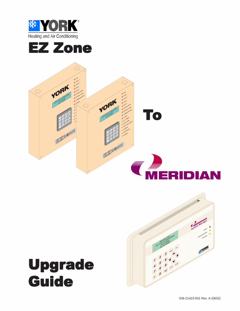
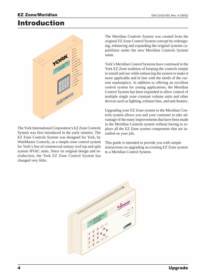
The York International Corporation’s EZ Zone ControlsSystem was first introduced in the early nineties. TheEZ Zone Controls System was designed for York, byWattMaster Controls, as a simple zone control systemfor York’s line of commercial unitary roof top and splitsystem HVAC units. Since its original design and in-troduction, the York EZ Zone Control System haschanged very little.
Introduction
FAN
COO
L1
COO
L2
HEAT1
HEAT2
BYPASSO
PEN
BYPASSCLO
SE
COM
MUNIC
ATION
ALARM
A=
ALLZO
NES
B=
EACHZO
NE
C=
HVACUNIT
/CLEAR
D=
ALARMS
#=
STEP/ENTER
* =DECIM
AL
+
+
+
+
Meridian
COOL
MODE
04-08-96
03:48PMFRI
OCCUPIED
NOALARMS
2
8
5
0
A
C
B
D
1
7
4
*
3
9
6
#
YO
RK
The Meridian Controls System was created from theoriginal EZ Zone Control System concept by redesign-ing, enhancing and expanding the original systems ca-pabilities under the new Meridian Controls Systemname.
York’s Meridian Control Systems have continued in theYork EZ Zone tradition of keeping the controls simpleto install and use while enhancing the system to make itmore applicable and in line with the needs of the cur-rent marketplace. In addition to offering an excellentcontrol system for zoning applications, the MeridianControl System has been expanded to allow control ofmultiple single zone constant volume units and otherdevices such as lighting, exhaust fans, and unit heaters.
Upgrading your EZ Zone system to the Meridian Con-trols system allows you and your customer to take ad-vantage of the many improvements that have been madein the Meridian Controls system without having to re-place all the EZ Zone system components that are in-stalled on your job.
This guide is intended to provide you with simpleinstructions on upgrading an existing EZ Zone systemto a Meridian Control System.
Clear Window
Area
6
5
4
DEC
7MIN
US
0
CLEAR9
8
1
3
2
MENU
Overr
ide
Com
munic
ation
ENTER
ESC
Ala
rmSystem
Manager
-
Merid
ianPlus
05/17/0
003:3
8PMW
ED
OCCUPIED
NOALARM
S
Heating and Air Conditio
ning
®
EZ Zone/Meridian
Upgrade 5
036-21423-001 Rev. A (0602)
The basic steps required to upgrade your EZZone system to a Meridian system are:
� Determine what EZ Zone componentsare currently installed on the system.
� Replace the existing EZ-Zone MasterController board with an MeridianZone Manager controller board
� Replace the existing EZ ZoneEPROM’s in each Zone Controllerwith a new Meridian EPROM.
� Install return air and outside airtemperature sensors
EZ Zone to Meridian upgrade allows you toretain:
� All existing wiring
� Master Controller enclosure withkeypad and display
� Existing supply air and static pressuresensors
� Existing bypass damper
� All Zone Dampers
� * All Zone Controllers
� Room sensors
� * Modem Linc Central
� * All Master Interface Boards
� All Fan Terminal Controllers
EZ Zone Upgrade Overview
After upgrading your system from EZ Zone toMeridian, you will be able to take advantageof many new enhancements including:
� Damper actuators can be programmedfor direct or reverse operation
� Full modulating economizer controlcapability including optional wetbulbeconomizer control
� Outside air temperature sensor provideslockout function for both heating andcooling. When converted to MeridianPlus system only one outside air sensoris required for the entire system
� Contact closure input for dirty filterstatus
� Global and individual zone overridemodes
� Zones can be set for voting ornonvoting status
� Room sensor slide can be programmed ± 0° F to ± 5° F adjustmentfrom setpoint
� Staging delays, minimum off times,and changeover intervals areprogrammable
� Sensor offset calibration to correctsensor errors due to poor location
� MeridianView enhanced graphicalcomputer front end software availablewhen CommLink and a PC are used
� System Manager operator interfaceallows all controllers to be accessed fromone central location
* These controllers can be retained but they will re-quire an EPROM chip upgrade to be compatiblewith the Meridian System.
EZ Zone/Meridian
6 Upgrade
036-21423-001 Rev. A (0602)
Component Descriptions
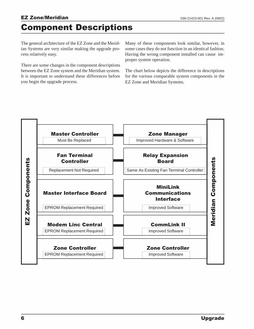
The general architecture of the EZ Zone and the Merid-ian Systems are very similar making the upgrade pro-cess relatively easy.
There are some changes in the component descriptionsbetween the EZ Zone system and the Meridian system.It is important to understand these differences beforeyou begin the upgrade process.
Many of these components look similar, however, insome cases they do not function in an identical fashion.Having the wrong component installed can cause im-proper system operation.
The chart below depicts the difference in descriptionsfor the various comparable system components in theEZ Zone and Meridian Systems.
Master Controller Zone Manager
Fan Terminal
Controller
Master Interface Board
MiniLink
Communications
Interface
Modem Linc Central CommLink II
Zone Controller Zone Controller
EZ
Z
one C
om
ponents
Merid
ian C
om
ponents
Relay Expansion
Board
Must Be Replaced Improved Hardware & Software
Replacement Not Required
EPROM Replacement Required
EPROM Replacement Required
EPROM Replacement Required
Same As Existing Fan Terminal Controller
Improved Software
Improved Software
Improved Software
EZ Zone/Meridian
Upgrade 7
036-21423-001 Rev. A (0602)
Upgrade Package Selection
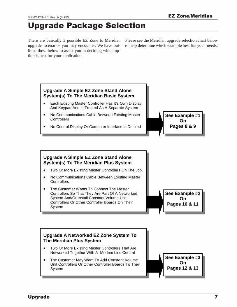
There are basically 3 possible EZ Zone to Meridianupgrade scenarios you may encounter. We have out-lined these below to assist you in deciding which op-tion is best for your application.
Please see the Meridian upgrade selection chart belowto help determine which example best fits your needs.
Upgrade A Simple EZ Zone Stand AloneSystem(s) To The Meridian Basic System
• Each Existing Master Controller Has It’s Own DisplayAnd Keypad And Is Treated As A Separate System
• No Communications Cable Between Existing MasterControllers
• No Central Display Or Computer Interface Is Desired
See Example #1On
Pages 8 & 9
See Example #2On
Pages 10 & 11
See Example #3On
Pages 12 & 13
Upgrade A Simple EZ Zone Stand AloneSystem(s) To The Meridian Plus System
• Two Or More Existing Master Controllers On The Job.
• No Communications Cable Between Existing MasterControllers
• The Customer Wants To Connect The MasterControllers So That They Are Part Of A NetworkedSystem And/Or Install Constant Volume UnitControllers Or Other Controller Boards On TheirSystem
Upgrade A Networked EZ Zone System ToThe Meridian Plus System
• Two Or More Existing Master Controllers That AreNetworked Together With A Modem Linc Central
• The Customer May Want To Add Constant VolumeUnit Controllers Or Other Controller Boards To TheirSystem
EZ Zone/Meridian
8 Upgrade
036-21423-001 Rev. A (0602)
Example #1:
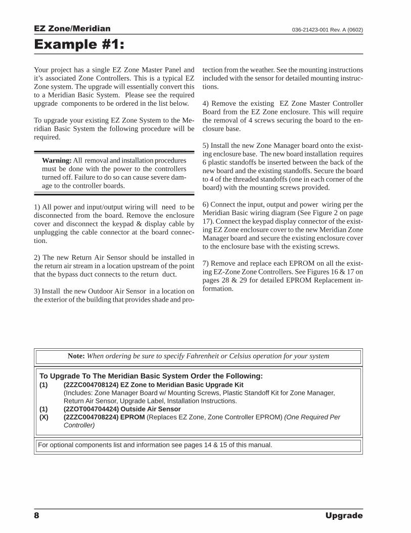
Your project has a single EZ Zone Master Panel andit’s associated Zone Controllers. This is a typical EZZone system. The upgrade will essentially convert thisto a Meridian Basic System. Please see the requiredupgrade components to be ordered in the list below.
To upgrade your existing EZ Zone System to the Me-ridian Basic System the following procedure will berequired.
Warning: All removal and installation proceduresmust be done with the power to the controllersturned off. Failure to do so can cause severe dam-age to the controller boards.
1) All power and input/output wiring will need to bedisconnected from the board. Remove the enclosurecover and disconnect the keypad & display cable byunplugging the cable connector at the board connec-tion.
2) The new Return Air Sensor should be installed inthe return air stream in a location upstream of the pointthat the bypass duct connects to the return duct.
3) Install the new Outdoor Air Sensor in a location onthe exterior of the building that provides shade and pro-
tection from the weather. See the mounting instructionsincluded with the sensor for detailed mounting instruc-tions.
4) Remove the existing EZ Zone Master ControllerBoard from the EZ Zone enclosure. This will requirethe removal of 4 screws securing the board to the en-closure base.
5) Install the new Zone Manager board onto the exist-ing enclosure base. The new board installation requires6 plastic standoffs be inserted between the back of thenew board and the existing standoffs. Secure the boardto 4 of the threaded standoffs (one in each corner of theboard) with the mounting screws provided.
6) Connect the input, output and power wiring per theMeridian Basic wiring diagram (See Figure 2 on page17). Connect the keypad display connector of the exist-ing EZ Zone enclosure cover to the new Meridian ZoneManager board and secure the existing enclosure coverto the enclosure base with the existing screws.
7) Remove and replace each EPROM on all the exist-ing EZ-Zone Zone Controllers. See Figures 16 & 17 onpages 28 & 29 for detailed EPROM Replacement in-formation.
To Upgrade To The Meridian Basic System Order the Following:(1) (2ZZC004708124) EZ Zone to Meridian Basic Upgrade Kit
(Includes: Zone Manager Board w/ Mounting Screws, Plastic Standoff Kit for Zone Manager,Return Air Sensor, Upgrade Label, Installation Instructions.
(1) (2ZOT004704424) Outside Air Sensor(X) (2ZZC004708224) EPROM (Replaces EZ Zone, Zone Controller EPROM) (One Required Per
Controller)
Note: When ordering be sure to specify Fahrenheit or Celsius operation for your system
For optional components list and information see pages 14 & 15 of this manual.
EZ Zone/Meridian
Upgrade 9
036-21423-001 Rev. A (0602)
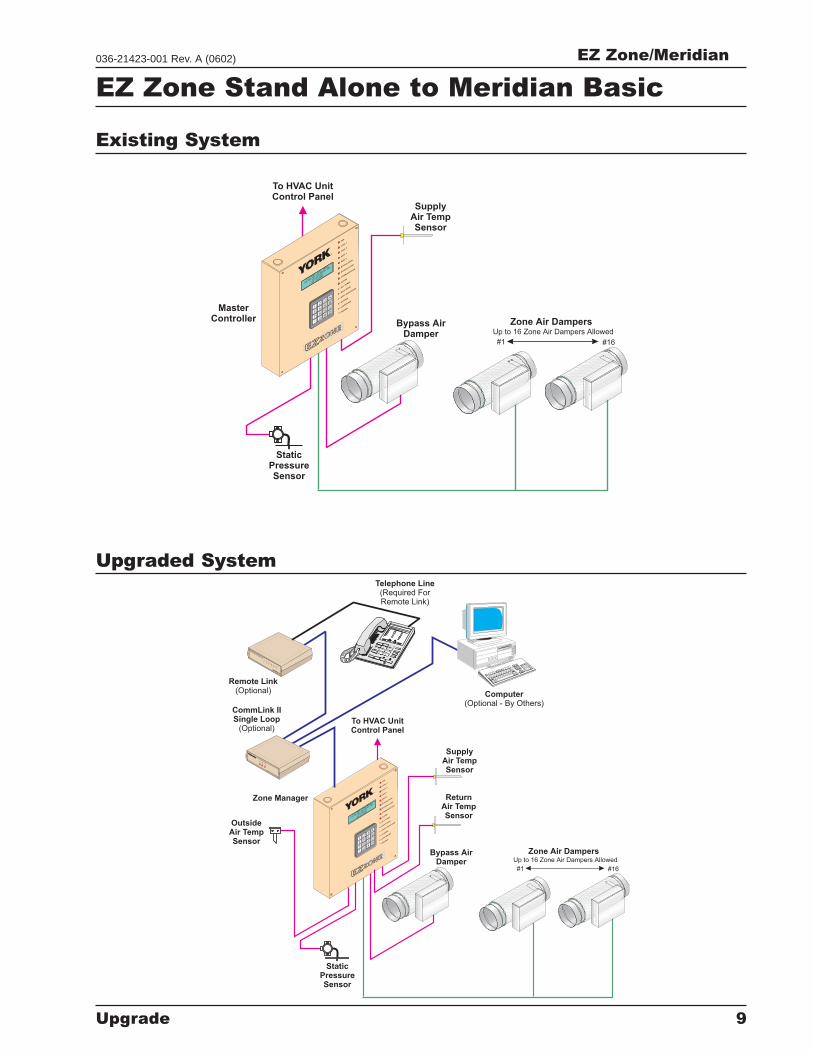
EZ Zone Stand Alone to Meridian Basic
Zone Air DampersUp to 16 Zone Air Dampers Allowed
SupplyAir TempSensor
To HVAC UnitControl Panel
MasterController
Bypass AirDamper
StaticPressureSensor
#1 #16
FAN
COO
L1
COO
L2
HEAT1
HEAT2
BYPASSO
PEN
BYPASSCLO
SE
COM
MUNIC
ATION
ALARM
A=
ALLZO
NES
B=
EACHZO
NE
C=
HVACUNIT
/CLEAR
D=
ALARMS
#=
STEP/ENTER
* =DECIM
AL
+
+
+
+
EZ-ZONECOOL
MODE
04-08-96
03:48PMFRI
OCCUPIED
NOALARMS
2
8
5
0
A
C
B
D
1
7
4
*
3
9
6
#
YORK
®
Zone Air DampersUp to 16 Zone Air Dampers Allowed
SupplyAir TempSensor
To HVAC UnitControl Panel
Zone Manager
Bypass AirDamper
StaticPressureSensor
#1 #16
FAN
COO
L1
COO
L2
HEAT1
HEAT2
BYPASSO
PEN
BYPASSCLO
SE
COM
MUNIC
ATION
ALARM
A=
ALLZO
NES
B=
EACHZO
NE
C=
HVACUNIT
/CLEAR
D=
ALARMS
#=
STEP/ENTER
* =DECIM
AL
+
+
+
+
EZ-ZONECOOL
MODE
04-08-96
03:48PMFRI
OCCUPIED
NOALARMS
2
8
5
0
A
C
B
D
1
7
4
*
3
9
6
#
YORK
®
ReturnAir TempSensor
OutsideAir TempSensor
8
9
7
4
5
6
3
2
1
#
0*
Remote Link(Optional)
CommLink IISingle Loop
(Optional)
W
C
LI
ATTMASTER
ONTRO
S,NC
CO
MM
LINK
II
CO
MM
LINK
II
L
C
M
M
O
O
O
O
M
D
P
PE
Computer(Optional - By Others)
SychronousData
Link
C
O
N
T
R
O
L
S
SIG
DE
T
RD
Y
SN
D
RE
C
PW
R
Telephone Line(Required ForRemote Link)
Upgraded System
Existing System
EZ Zone/Meridian
10 Upgrade
036-21423-001 Rev. A (0602)
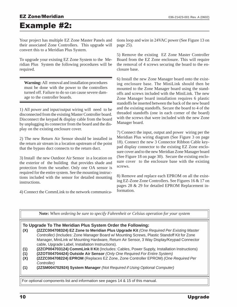
Example #2:
Your project has multiple EZ Zone Master Panels andtheir associated Zone Controllers. This upgrade willconvert this to a Meridian Plus System.
To upgrade your existing EZ Zone System to the Me-ridian Plus System the following procedures will berequired.
Warning: All removal and installation proceduresmust be done with the power to the controllersturned off. Failure to do so can cause severe dam-age to the controller boards.
1) All power and input/output wiring will need to bedisconnected from the existing Master Controller board.Disconnect the keypad & display cable from the boardby unplugging its connector from the board and the dis-play on the existing enclosure cover.
2) The new Return Air Sensor should be installed inthe return air stream in a location upstream of the pointthat the bypass duct connects to the return duct.
3) Install the new Outdoor Air Sensor in a location onthe exterior of the building that provides shade andprotection from the weather. Only one OA sensor isrequired for the entire system. See the mounting instruc-tions included with the sensor for detailed mountinginstructions.
4) Connect the CommLink to the network communica-
tions loop and wire in 24VAC power (See Figure 13 onpage 25).
5) Remove the existing EZ Zone Master ControllerBoard from the EZ Zone enclosure. This will requirethe removal of 4 screws securing the board to the en-closure base.
6) Install the new Zone Manager board onto the exist-ing enclosure base. The MiniLink should then bemounted to the Zone Manager board using the stand-offs and screws included with the MiniLink. The newZone Manager board installation requires 6 plasticstandoffs be inserted between the back of the new boardand the existing standoffs. Secure the board to 4 of thethreaded standoffs (one in each corner of the board)with the screws that were included with the new ZoneManager board.
7) Connect the input, output and power wiring per theMeridian Plus wiring diagram (See Figure 3 on page18). Connect the new 3 Connector Ribbon Cable key-pad display connector to the existing EZ Zone enclo-sure cover and to the new Meridian Zone Manager board(See Figure 18 on page 30). Secure the existing enclo-sure cover to the enclosure base with the existingscrews.
8) Remove and replace each EPROM on all the exist-ing EZ-Zone Zone Controllers. See Figures 16 & 17 onpages 28 & 29 for detailed EPROM Replacement in-formation.
To Upgrade To The Meridian Plus System Order the Following:(X) (2ZZC004708324) EZ Zone to Meridian Plus Upgrade Kit (One Required Per Existing Master
Controller) (Includes: Zone Manager Board w/ Mounting Screws, Plastic Standoff Kit for ZoneManager, MiniLink w/ Mounting Hardware, Return Air Sensor, 3 Way Display/Keypad Connectorcable, Upgrade Label, Installation Instructions).
(1) (2ZCP004703124) CommLink II Kit (Includes: Cables, Power Supply, Installation Instructions)(1) (2ZOT004704424) Outside Air Sensor (Only One Required For Entire System)(X) (2ZZC004708224) EPROM (Replaces EZ Zone, Zone Controller EPROM) (One Required Per
Controller)(1) (2ZSM004702924) System Manager (Not Required if Using Optional Computer)
Note: When ordering be sure to specify Fahrenheit or Celsius operation for your system
For optional components list and information see pages 14 & 15 of this manual.
EZ Zone/Meridian
Upgrade 11
036-21423-001 Rev. A (0602)
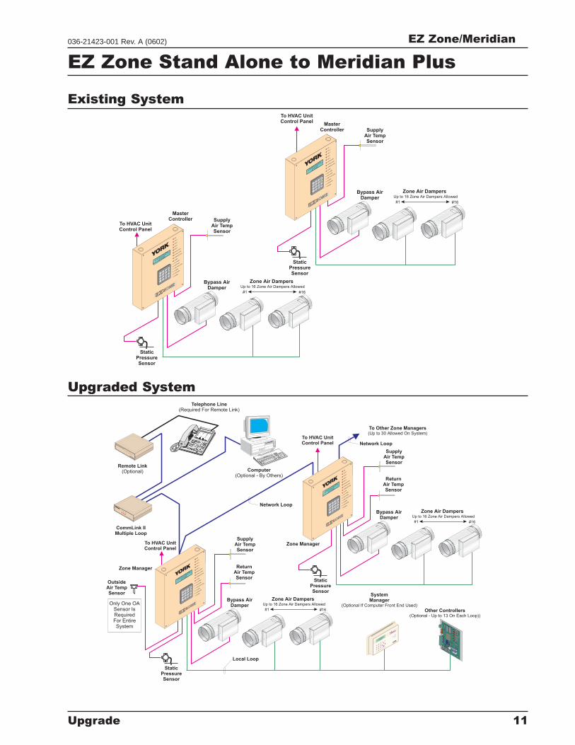
EZ Zone Stand Alone to Meridian Plus
Zone Air Dampers
Zone Air Dampers
Up to 16 Zone Air Dampers Allowed
Up to 16 Zone Air Dampers Allowed
SupplyAir TempSensor
SupplyAir TempSensor
To HVAC UnitControl Panel
To HVAC UnitControl Panel
MasterController
MasterController
Bypass AirDamper
Bypass AirDamper
StaticPressureSensor
StaticPressureSensor
#1
#1
#16
#16
FAN
COO
L1
COO
L2
HEAT1
HEAT2
BYPASSO
PEN
BYPASSCLO
SE
COM
MUNIC
ATION
ALARM
A=
ALLZO
NES
B=
EACHZO
NE
C=
HVACUNIT
/CLEAR
D=
ALARMS
#=
STEP/ENTER
* =DECIM
AL
+
+
+
+
EZ-ZONECOOL
MODE
04-08-96
03:48PMFRI
OCCUPIED
NOALARMS
2
8
5
0
A
C
B
D
1
7
4
*
3
9
6
#
YORK
®
FAN
COO
L1
COO
L2
HEAT1
HEAT2
BYPASSO
PEN
BYPASSCLO
SE
COM
MUNIC
ATION
ALARM
A=
ALLZO
NES
B=
EACHZO
NE
C=
HVACUNIT
/CLEAR
D=
ALARMS
#=
STEP/ENTER
* =DECIM
AL
+
+
+
+
EZ-ZONECOOL
MODE
04-08-96
03:48PMFRI
OCCUPIED
NOALARMS
2
8
5
0
A
C
B
D
1
7
4
*
3
9
6
#
YORK
®
Zone Air Dampers
Zone Air Dampers
Up to 16 Zone Air Dampers Allowed
Up to 16 Zone Air Dampers Allowed
SupplyAir TempSensor
SupplyAir TempSensor
To Other Zone Managers(Up to 30 Allowed On System)
To HVAC UnitControl Panel
Network Loop
Network Loop
Local Loop
Zone Manager
Zone Manager
To HVAC UnitControl Panel
Bypass AirDamper
Bypass AirDamper
StaticPressureSensor
StaticPressureSensor
#1
#1
#16
#16
ReturnAir TempSensor
OutsideAir TempSensor
ReturnAir TempSensor
Only One OASensor IsRequiredFor EntireSystem
8
9
7
4
5
6
3
2
1
#
0*
Remote Link(Optional)
CommLink IIMultiple Loop
W
C
LI
ATTMASTER
ONTRO
S,NC
CO
MM
LINK
II
CO
MM
LINK
II
L
C
M
M
O
O
O
O
M
D
P
PE
Computer(Optional - By Others)
SychronousData
Link
C
O
N
T
R
O
L
S
SIG
DE
T
RD
Y
SN
D
RE
C
PW
R
Telephone Line(Required For Remote Link)
FAN
COO
L1
COO
L2
HEAT1
HEAT2
BYPASSO
PEN
BYPASSCLO
SE
COM
MUNIC
ATION
ALARM
A=
ALLZO
NES
B=
EACHZO
NE
C=
HVACUNIT
/CLEAR
D=
ALARMS
#=
STEP/ENTER
* =DECIM
AL
+
+
+
+
Meridian
COOL
MODE
04-08-96
03:48PMFRI
OCCUPIED
NOALARMS
2
8
5
0
A
C
B
D
1
7
4
*
3
9
6
#
YO
RK
FAN
COO
L1
COO
L2
HEAT1
HEAT2
BYPASSO
PEN
BYPASSCLO
SE
COM
MUNIC
ATION
ALARM
A=
ALLZO
NES
B=
EACHZO
NE
C=
HVACUNIT
/CLEAR
D=
ALARMS
#=
STEP/ENTER
* =DECIM
AL
+
+
+
+
Meridian
COOL
MODE
04-08-96
03:48PMFRI
OCCUPIED
NOALARMS
2
8
5
0
A
C
B
D
1
7
4
*
3
9
6
#
YO
RK
SystemManager
(Optional If Computer Front End Used)
Other Controllers(Optional - Up to 13 On Each Loop))
Clear Window
Area
6
5
4
DEC
7MIN
US
0
CLEAR9
8
1
3
2
MENU
Overr
ide
Com
munic
ation
ENTER
ESC
Ala
rmSystem
Manager
-
Merid
ianPlus
05/17/0
003:3
8PMW
ED
OCCUPIED
NOALARM
S
Heating and Air Conditio
ning
®
Upgraded System
Existing System
EZ Zone/Meridian
12 Upgrade
036-21423-001 Rev. A (0602)
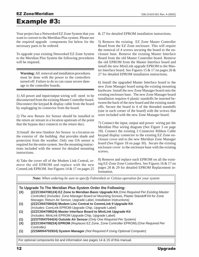
Example #3:
Your project has a Networked EZ Zone System that youwant to convert to the Meridian Plus system. Please seethe required upgrade components list below for thenecessary parts to be ordered.
To upgrade your existing Networked EZ Zone Systemto the Meridian Plus System the following procedureswill be required.
Warning: All removal and installation proceduresmust be done with the power to the controllersturned off. Failure to do so can cause severe dam-age to the controller boards.
1) All power and input/output wiring will need to bedisconnected from the existing Master Controller board.Disconnect the keypad & display cable from the boardby unplugging its connector from the board.
2) The new Return Air Sensor should be installed inthe return air stream in a location upstream of the pointthat the bypass duct connects to the return duct.
3) Install the new Outdoor Air Sensor in a location onthe exterior of the building that provides shade andprotection from the weather. Only one OA sensor isrequired for the entire system. See the mounting instruc-tions included with the sensor for detailed mountinginstructions.
4) Take the cover off of the Modem Link Central, re-move the old EPROM and replace with the newCommLink EPROM. See Figures 14 & 17 on pages 25
& 27 for detailed EPROM installation instructions.
5) Remove the existing EZ Zone Master ControllerBoard from the EZ Zone enclosure. This will requirethe removal of 4 screws securing the board to the en-closure base. Remove the existing Master InterfaceBoard from the old Master Controller board. Removethe old EPROM from the Master Interface board andinstall the new MiniLink upgrade EPROM to the Mas-ter Interface board. See Figures 15 & 17 on pages 26 &27 for detailed EPROM installation instructions.
6) Install the upgraded Master Interface board to thenew Zone Manager board using the existing mountinghardware. Install the new Zone Manager board onto theexisting enclosure base. The new Zone Manager boardinstallation requires 6 plastic standoffs be inserted be-tween the back of the new board and the existing stand-offs. Secure the board to 4 of the threaded standoffs(one in each corner of the board) with the screws thatwere included with the new Zone Manager board.
7) Connect the input, output and power wiring per theMeridian Plus wiring diagram (See Figure 3 on page18). Connect the existing 3 Connector Ribbon Cablekeypad display connector to the existing EZ Zone en-closure cover and to the new Meridian Zone Managerboard (See Figure 18 on page 30). Secure the existingenclosure cover to the enclosure base with the existingscrews.
8) Remove and replace each EPROM on all the exist-ing EZ-Zone Zone Controllers. See Figures 16 & 17 onpages 28 & 29 for detailed EPROM Replacement in-formation.
To Upgrade To The Meridian Plus System Order the Following:(X) (2ZZC004708124) EZ Zone to Meridian Basic Upgrade Kit (One Required Per Existing Master
Controller) (Includes: Zone Manager Board w/ Mounting Screws, Plastic Standoff Kit for ZoneManager, Return Air Sensor, Upgrade Label, Installation Instructions)
(1) (2ZZC004708424) Modem Linc Central to CommLink II Upgrade Kit(Includes: ComLink EPROM Upgrade Chip, Upgrade Label)
(1) (2ZZC004708524) Master Interface Board to MiniLink Upgrade Kit(Includes: MiniLink EPROM Upgrade Chip, Upgrade Label)
(1) (2ZOT004704424) Outside Air Sensor (Only One Required Per System)(X) (2ZZC004708224) EPROM (Replaces EZ Zone, Zone Controller EPROM) (One Required Per
Controller)(1) (2ZSM004702924) System Manager (Not Required if Using Optional Computer)
Note: When ordering be sure to specify Fahrenheit or Celsius operation for your system
For optional components list and information see pages 14 & 15 of this manual.
EZ Zone/Meridian
Upgrade 13
036-21423-001 Rev. A (0602)
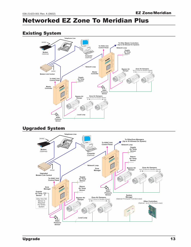
Networked EZ Zone To Meridian Plus
Zone Air Dampers
Zone Air Dampers
Up to 16 Zone Air Dampers Allowed
Up to 16 Zone Air Dampers Allowed
SupplyAir TempSensor
SupplyAir TempSensor
To Other Master Controllers(Up to 30 Allowed On System)
To HVAC UnitControl Panel
Network Loop
Network Loop
Local Loop
To HVAC UnitControl Panel
Bypass AirDamper
Bypass AirDamper
StaticPressureSensor
StaticPressureSensor
#1
#1
#16
#16
8
9
7
4
5
6
3
2
1
#
0*
Modem(Optional)
Modem Link Central
24VAC
24VAC
W
C
LI
ATTMASTER
ONTRO
S,NC
CO
MM
LINK
II
CO
MM
LINK
II
L
C
M
M
O
O
O
O
M
D
P
PE
Computer(Optional)
Telephone Line
FAN
COO
L1
COO
L2
HEAT1
HEAT2
BYPASSO
PEN
BYPASSCLO
SE
COM
MUNIC
ATION
ALARM
A=
ALLZO
NES
B=
EACHZO
NE
C=
HVACUNIT
/CLEAR
D=
ALARMS
#=
STEP/ENTER
* =DECIM
AL
+
+
+
+
Meridian
COOL
MODE
04-08-96
03:48PMFRI
OCCUPIED
NOALARMS
2
8
5
0
A
C
B
D
1
7
4
*
3
9
6
#
YO
RK
FAN
COO
L1
COO
L2
HEAT1
HEAT2
BYPASSO
PEN
BYPASSCLO
SE
COM
MUNIC
ATION
ALARM
A=
ALLZO
NES
B=
EACHZO
NE
C=
HVACUNIT
/CLEAR
D=
ALARMS
#=
STEP/ENTER
* =DECIM
AL
+
+
+
+
Meridian
COOL
MODE
04-08-96
03:48PMFRI
OCCUPIED
NOALARMS
2
8
5
0
A
C
B
D
1
7
4
*
3
9
6
#
YO
RK
MasterController
MasterController
Zone Air Dampers
Zone Air Dampers
Up to 16 Zone Air Dampers Allowed
Up to 16 Zone Air Dampers Allowed
SupplyAir TempSensor
SupplyAir TempSensor
To OtherZone Managers(Up to 30 Allowed On System)
To HVAC UnitControl Panel
Network Loop
Network Loop
Local Loop
To HVAC UnitControl Panel
Bypass AirDamper
Bypass AirDamper
StaticPressureSensor
StaticPressureSensor
#1
#1
#16
#16
8
9
7
4
5
6
3
2
1
#
0*
Modem(Optional)
UpgradedModem Link Central
24VAC
24VAC
W
C
LI
ATTMASTER
ONTRO
S,NC
CO
MM
LINKII
CO
MM
LINK
II
L
C
M
M
O
O
O
O
M
D
P
PE
Computer(Optional)
Telephone Line
FAN
COO
L1
COO
L2
HEAT1
HEAT2
BYPASSO
PEN
BYPASSCLO
SE
COM
MUNIC
ATION
ALARM
A=
ALLZO
NES
B=
EACHZO
NE
C=
HVACUNIT
/CLEAR
D=
ALARMS
#=
STEP/ENTER
* =DECIM
AL
+
+
+
+
Meridian
COOL
MODE
04-08-96
03:48PMFRI
OCCUPIED
NOALARMS
2
8
5
0
A
C
B
D
1
7
4
*
3
9
6
#
YO
RK
FAN
COO
L1
COO
L2
HEAT1
HEAT2
BYPASSO
PEN
BYPASSCLO
SE
COM
MUNIC
ATION
ALARM
A=
ALLZO
NES
B=
EACHZO
NE
C=
HVACUNIT
/CLEAR
D=
ALARMS
#=
STEP/ENTER
* =DECIM
AL
+
+
+
+
Meridian
COOL
MODE
04-08-96
03:48PMFRI
OCCUPIED
NOALARMS
2
8
5
0
A
C
B
D
1
7
4
*
3
9
6
#
YO
RK
ZoneManager
ZoneManager
ReturnAir TempSensor
OutsideAir TempSensor
ReturnAir TempSensor
Only One OASensor IsRequiredFor EntireSystem
SystemManager
(Optional If Computer Front End Used)
Other Controllers(Optional - Up to 13 On Each Loop))
Clear Window
Area
6
5
4
DEC
7MIN
US
0
CLEAR9
8
1
3
2
MENU
Overr
ide
Com
munic
ation
ENTER
ESC
Ala
rmSystem
Manager
-
Merid
ianPlus
05/17/0
003:3
8PMW
ED
OCCUPIED
NOALARM
S
Heating and Air Conditio
ning
®
Upgraded System
Existing System
EZ Zone/Meridian
14 Upgrade
036-21423-001 Rev. A (0602)
Optional Controllers and Accessories
In addition to the standard Zone Manager and ZoneControllers, York offers many other controllers and ac-cessories to enhance your new Meridian System. Op-tional Controllers that are available for use with theMeridian Plus system include the CV, CV-C, GPC, Op-timal Start Scheduler, Lighting Panel Controller andWetbulb Module. These controllers are not availablefor use with the Meridian Basic System. To utilize anyof the optional controllers you must upgrade your sys-tem to the Meridian Plus configuration. Accessories that
are available for use with either the Meridian Plus orBasic System include the CommLink II Communica-tions Interface, Remote Link, Room Sensors, RoundZone Dampers and Rectangular Zone Dampers. Yorkalso offers Communication Cable that is color codedand labeled for the network communications loop andlocal communications loop.
Following are brief descriptions of the optional con-trollers and accessories that are available.
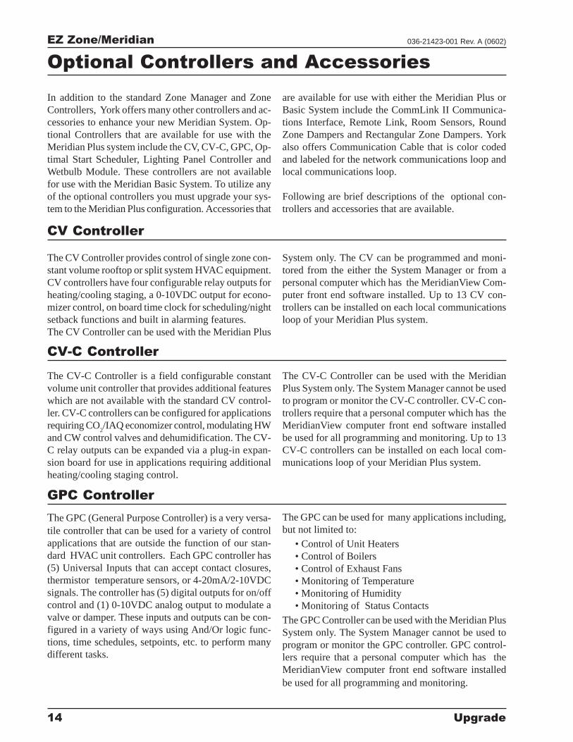
CV Controller
The CV Controller provides control of single zone con-stant volume rooftop or split system HVAC equipment.CV controllers have four configurable relay outputs forheating/cooling staging, a 0-10VDC output for econo-mizer control, on board time clock for scheduling/nightsetback functions and built in alarming features.The CV Controller can be used with the Meridian Plus
System only. The CV can be programmed and moni-tored from the either the System Manager or from apersonal computer which has the MeridianView Com-puter front end software installed. Up to 13 CV con-trollers can be installed on each local communicationsloop of your Meridian Plus system.
CV-C Controller
The CV-C Controller is a field configurable constantvolume unit controller that provides additional featureswhich are not available with the standard CV control-ler. CV-C controllers can be configured for applicationsrequiring CO
2/IAQ economizer control, modulating HW
and CW control valves and dehumidification. The CV-C relay outputs can be expanded via a plug-in expan-sion board for use in applications requiring additionalheating/cooling staging control.
The CV-C Controller can be used with the MeridianPlus System only. The System Manager cannot be usedto program or monitor the CV-C controller. CV-C con-trollers require that a personal computer which has theMeridianView computer front end software installedbe used for all programming and monitoring. Up to 13CV-C controllers can be installed on each local com-munications loop of your Meridian Plus system.
GPC Controller
The GPC (General Purpose Controller) is a very versa-tile controller that can be used for a variety of controlapplications that are outside the function of our stan-dard HVAC unit controllers. Each GPC controller has(5) Universal Inputs that can accept contact closures,thermistor temperature sensors, or 4-20mA/2-10VDCsignals. The controller has (5) digital outputs for on/offcontrol and (1) 0-10VDC analog output to modulate avalve or damper. These inputs and outputs can be con-figured in a variety of ways using And/Or logic func-tions, time schedules, setpoints, etc. to perform manydifferent tasks.
The GPC can be used for many applications including,but not limited to:
• Control of Unit Heaters• Control of Boilers• Control of Exhaust Fans• Monitoring of Temperature• Monitoring of Humidity• Monitoring of Status Contacts
The GPC Controller can be used with the Meridian PlusSystem only. The System Manager cannot be used toprogram or monitor the GPC controller. GPC control-lers require that a personal computer which has theMeridianView computer front end software installedbe used for all programming and monitoring.
EZ Zone/Meridian
Upgrade 15
036-21423-001 Rev. A (0602)
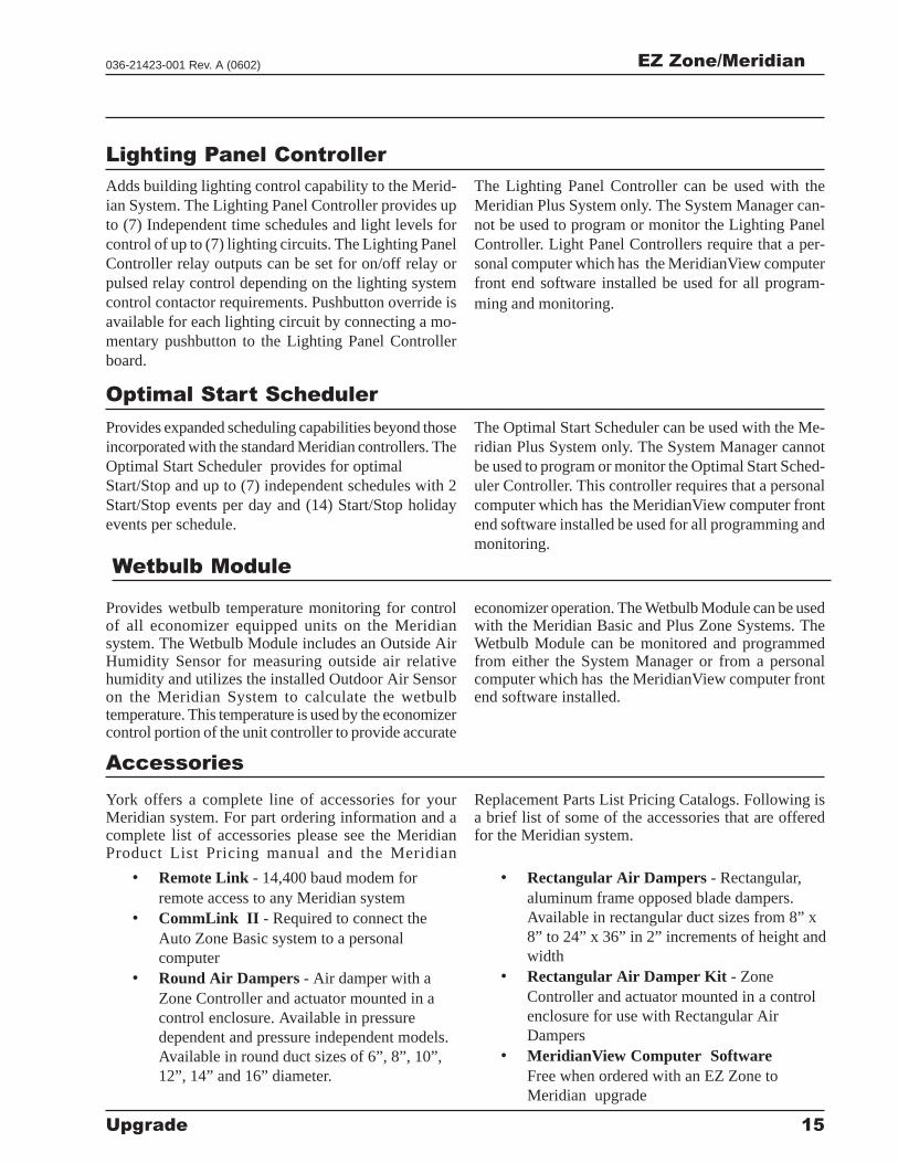
Lighting Panel Controller
Adds building lighting control capability to the Merid-ian System. The Lighting Panel Controller provides upto (7) Independent time schedules and light levels forcontrol of up to (7) lighting circuits. The Lighting PanelController relay outputs can be set for on/off relay orpulsed relay control depending on the lighting systemcontrol contactor requirements. Pushbutton override isavailable for each lighting circuit by connecting a mo-mentary pushbutton to the Lighting Panel Controllerboard.
The Lighting Panel Controller can be used with theMeridian Plus System only. The System Manager can-not be used to program or monitor the Lighting PanelController. Light Panel Controllers require that a per-sonal computer which has the MeridianView computerfront end software installed be used for all program-ming and monitoring.
Optimal Start Scheduler
Provides expanded scheduling capabilities beyond thoseincorporated with the standard Meridian controllers. TheOptimal Start Scheduler provides for optimalStart/Stop and up to (7) independent schedules with 2Start/Stop events per day and (14) Start/Stop holidayevents per schedule.
The Optimal Start Scheduler can be used with the Me-ridian Plus System only. The System Manager cannotbe used to program or monitor the Optimal Start Sched-uler Controller. This controller requires that a personalcomputer which has the MeridianView computer frontend software installed be used for all programming andmonitoring.
Wetbulb Module
Provides wetbulb temperature monitoring for controlof all economizer equipped units on the Meridiansystem. The Wetbulb Module includes an Outside AirHumidity Sensor for measuring outside air relativehumidity and utilizes the installed Outdoor Air Sensoron the Meridian System to calculate the wetbulbtemperature. This temperature is used by the economizercontrol portion of the unit controller to provide accurate
economizer operation. The Wetbulb Module can be usedwith the Meridian Basic and Plus Zone Systems. TheWetbulb Module can be monitored and programmedfrom either the System Manager or from a personalcomputer which has the MeridianView computer frontend software installed.
Accessories
York offers a complete line of accessories for yourMeridian system. For part ordering information and acomplete list of accessories please see the MeridianProduct List Pricing manual and the Meridian
Replacement Parts List Pricing Catalogs. Following isa brief list of some of the accessories that are offeredfor the Meridian system.
• Remote Link - 14,400 baud modem forremote access to any Meridian system
• CommLink II - Required to connect theAuto Zone Basic system to a personalcomputer
• Round Air Dampers - Air damper with aZone Controller and actuator mounted in acontrol enclosure. Available in pressuredependent and pressure independent models.Available in round duct sizes of 6”, 8”, 10”,12”, 14” and 16” diameter.
• Rectangular Air Dampers - Rectangular,aluminum frame opposed blade dampers.Available in rectangular duct sizes from 8” x8” to 24” x 36” in 2” increments of height andwidth
• Rectangular Air Damper Kit - ZoneController and actuator mounted in a controlenclosure for use with Rectangular AirDampers
• MeridianView Computer SoftwareFree when ordered with an EZ Zone toMeridian upgrade
EZ Zone/Meridian
16 Upgrade
036-21423-001 Rev. A (0602)
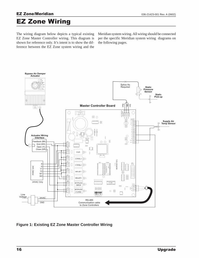
EZ Zone Wiring
The wiring diagram below depicts a typical existingEZ Zone Master Controller wiring. This diagram isshown for reference only. It’s intent is to show the dif-ference between the EZ Zone system wiring and the
Meridian system wiring. All wiring should be connectedper the specific Meridian system wiring diagrams onthe following pages.
StaticPick-up
StaticPressureSensor
Supply AirTemp Sensor
Splice AsRequired
LO HI
HV
AC
Un
it
24VAC Only
R
G
Y1
Y2
W1
W2
LineVoltage
GND
24VAC
Actuator WiringInterface
Feedback (BK)
Close (GR)
Open (YL)
Gnd (WH)
Bypass Air DamperActuator
Re
d
Blk
Grn
RS-485Communication cableto Zone Controllers
Master Controller Board
75
90
60
45
Figure 1: Existing EZ Zone Master Controller Wiring
EZ Zone/Meridian
Upgrade 17
036-21423-001 Rev. A (0602)
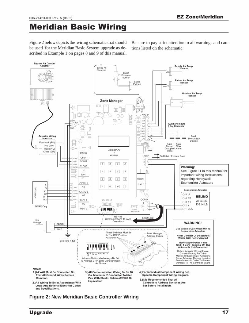
Meridian Basic Wiring
Figure 2: New Meridian Basic Controller Wiring
Figure 2 below depicts the wiring schematic that shouldbe used for the Meridian Basic System upgrade as de-scribed in Example 1 on pages 8 and 9 of this manual.
Be sure to pay strict attention to all warnings and cau-tions listed on the schematic.
Warning:See Figure 11 in this manual forimportant wiring instructionsregarding HoneywellEconomizer Actuators
Zone Manager
Feedback (BK)
Close (GR)
Open (YL)
Gnd (WH)
Notes:
1.)24 VAC Must Be Connected SoThat All Ground Wires RemainCommon.
3.)All Communication Wiring To Be 18Ga. Minimum, 2 Conductor TwistedPair With Shield. Belden #82760 OrEquivalent.
4.)For Individual Component Wiring SeeSpecific Component Wiring Diagram.
5.)It Is Recommended That AllControllers Address Switches AreSet Before Installation.
2.)All Wiring To Be In Accordance WithLocal And National Electrical Codesand Specifications.
RS-485Communications To Zone
Controllers
Return Air Temp.Sensor
Supply Air Temp.Sensor
LineVoltage
HV
AC
Un
it
24VAC Only
Re
d
Blk
To Relief / Exhaust Fans
Grn
StaticPick-up
StaticPressureSensor
Splice AsRequired
LO HI
GND
24VAC
Belimo Actuator Wiring Shown.Consult Factory For Other
Models Of Economizer Actuators.Some Actuators Require IsolationTransformers In Order To PreventDamage To The Controller Board.
WARNING!
Use Extreme Care When WiringEconomizer Actuators
Never Connect Or DisconnectWiring With Power Applied!
Never Apply Power If TheGnd ( 1 Com ) Terminal On The
Actuator Is Not Connected.
See Note 1 &2
Outdoor Air Temp.Sensor
Aux3Forced
OccupiedMode
Aux1Economizer
Disable
Aux2FilterAlarm
Auxiliary Inputs( Dry Contacts )
R
G
Y1
Y2
W1
W2
Economizer Actuator
133 IN-LB
AF24-SR
1 COM
2 +
3 Y1
4 Y2
5 UBELIMO
Actuator WiringInterface
Bypass Air DamperActuator
C987
CABLE
R6
R5
HEAT 2 SW
1
W2
W1
Y2
HEAT2
HEAT1
COOL2
COOL1
FAN
HEAT 1
COOL 2
COOL 1
C 1992
1
1632
BNET
248
AD
D
COMM DRIVER
RS-485
75176
MADE IN U.S.A.
D1
7
D1
8
D1
9
D2
0
D2
1
D2
2
D2
3
D2
4
0* # D
R
SH
T
COMM
C1C2
+
P1
RIBBON
GN
D
06/11/95 03:48PM FRIAuto-Zone COOL MODE
G
Y1V6
V5
CLOSE
V4
V3
OPEN
GND
FDBK
FAN
CLOSE
OPEN
+
REC
+
GND
NE5090
4 5 6
KEYPAD
1 2 3
B
A
NO ALARM(S)OCCUPIED
LCD DISPLAY
&
++
24VAC
TB2
POWER
+
++
ADJUST
5.11V
PJ1
++PRESSU
RE
SEN
SO
RJA
CK
+5
V
SIG
BUSS
EXP
TB2
A2
G
OUTPUTS
ANALOG
A1
N.O.
CONTACTS
EXHAUST
AUX3
GND
GND
AUX2
AUX1
ANALOG
SAT
OAT
RAT
INPUTS
+12V
TB1
2
BYPASS
BYPASS
Local Loop
Address Switch Must Always Be SetTo Address 0 on Zone Manager Board
As Shown
Zone ManagerAddress Switch
These Switches Must BeIn The OFF PositionAs Shown
ADD
12
481632B
NET
AD
D
32BNE
T
16 8 4 12
OF
F>
OF
F>
RockerDown
RockerDown
75
90
60
45
EZ Zone/Meridian
18 Upgrade
036-21423-001 Rev. A (0602)
Zone Manager
Notes:
1.)24 VAC Must Be Connected SoThat All Ground Wires RemainCommon.
3.)All Communication Wiring To Be 18Ga. Minimum, 2 Conductor TwistedPair With Shield. Belden #82760 OrEquivalent.
5.)For Individual Component Wiring SeeSpecific Component Wiring Diagram.
2.)All Wiring To Be In Accordance WithLocal And National Electrical Codesand Specifications.
RS-485Communications To ZoneControllers, CV ControllersAnd/Or System Manager
Return Air Temp.Sensor
Supply Air Temp.Sensor
LineVoltage
HV
AC
Unit
24VAC Only
Red
Blk
To Relief / Exhaust Fans
Grn
StaticPick-up
StaticPressureSensor
Splice AsRequired
LO HI
GND
24VAC
Belimo Actuator Wiring ShownConsult Factory For Other
Models Of Economizer ActuatorsSome Actuators Require IsolationTransformers In Order To PreventDamage To The Controller Board.
WARNING!
Use Extreme Care When WiringEconomizer Actuators
Never Connect Or DisconnectWiring With Power Applied!
Never Apply Power If TheGnd ( 1 Com ) Terminal On The
Actuator Is Not Connected.
See Note 1 &2
+
+
++
+
++
+ +
HEAT2
HEAT1
COOL2
COOL1
FAN
R
2
8C
SW
1
16AB 24
AD
D
LOCALLOOP
Local Loop
T
SH
RTB3
COMM
T
SH
R
32
16
8
4
1
2
MINILINK
R9
R10
R8
I CEXP
PORT
PWR
V4
V3
CLOSE
OPEN
FDBK
REC
GND
GND
24VAC
AUX1
OPEN
K1
NETWORKLOOP
Network Loop RS-48519200 Baud
To Other ZoneManagers and/or
CommLink onSystem
SH
R
T
CLOSEK
2
NE5090
ANALOGOUTPUTS
A2
G
TB2
A1
N.O.
EXHAUSTCONTACTS
GND
GND
AUX3
AUX2
7824
D2
5
U1
4
VR
3
R4
0
ADJUST5.11V
C2
7
7812 C2
6V
R2
D1
D3
D4
D2
PJ1
PR
ES
SU
RE
SE
NS
OR
JA
CK
+5
V
R7
OAT
RAT
+12V
SAT
ANALOGINPUTS
GN
D
SIG
T
R
SHIELD
T
R
SHIELD
Outdoor Air Temp.Sensor
(See Note 4)
Aux3Forced
OccupiedMode
Aux1Economizer
Disable
Aux2FilterAlarm
Auxiliary Inputs( Dry Contacts )
R
G
Y1
Y2
W1
W2
Economizer Actuator
133 IN-LB
AF24-SR
1 COM
2 +
3 Y1
4 Y2
5 UBELIMO
Actuator WiringInterface
Bypass Air DamperActuator
4.)Only One Outside Air Sensor IsRequired Per System. It May BeConnected To Any CV Controller OrZone Manager On The System. If AWetbulb Module Controller Is Used TheOA Sensor Must Be Connected To TheWetbulb Module.
75
90
60
45
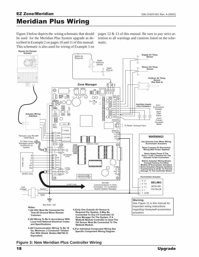
Meridian Plus Wiring
Figure 3: New Meridian Plus Controller Wiring
Figure 3 below depicts the wiring schematic that shouldbe used for the Meridian Plus System upgrade as de-scribed in Example 2 on pages 10 and 11 of this manual.This schematic is also used for wiring of Example 3 on
pages 12 & 13 of this manual. Be sure to pay strict at-tention to all warnings and cautions listed on the sche-matic.
Warning:See Figure 11 in this manual forimportant wiring instructionsregarding Honeywell economizeractuators
EZ Zone/Meridian
Upgrade 19
036-21423-001 Rev. A (0602)
1632
8421
Caution!The MiniLinks Must Have Address Switches Set Between 1And 30 (Up To 30 MiniLinks (Mounted on Zone Managers)Are Allowed Per Auto-Zone Plus System). The MiniLinksShould Be Addressed In Consecutive Order Starting WithAddress #1. Address #1 Must Be Present On The Loop ForThe System To Function.
Address Switch Shown IsSet For Address 1
Address Switch Must Always Be SetTo Address 17 on Zone Manager Board
As Shown
Address Switch Shown IsSet For Address 4
Zone ManagerAddress Switch
MiniLinkAddress Switch
These Switches Must BeIn The OFF PositionAs Shown
These Switches Must BeIn The OFF PositionAs Shown
Caution:The Power To The Zone Manager Must BeRemoved And Reconnected After Changing TheMiniLink Or Zone Manager Address Switch SettingsIn Order For Any Changes To Take Effect.
Caution:Disconnect All Communication Loop Wiring FromThe Zone Manger Before Removing Power.Reconnect Power And Then ReconnectCommunication Loop Wiring To Zone Manager.
ADD
ADD
ADD
12
481632B
NET
ADD
All Zone Managers On System Must BeAddressed As 17
Network Switch As ShownMust Be ON
The Address For Each MiniLinkMust Be Unique To The Other MiniLinksOn The Network Loop. Loop #1 MiniLink
Should Be Addressed As #1Loop #2 MiniLink Should Be Addressed
As #2 Etc..
ADD
AD
D
AD
D
32
32
32B
BN
ET
NE
T
16
1616
8
88
4
4
4
1
1
1
2
2
2
OFF >
OF
F>
OF
F>
Ro
cke
rD
ow
n
RockerDown
RockerDown
HEAT2
HEAT1
COOL2
COOL1
FAN
R
LOCALLOOPT
SH
RTB3
COMM
T
SH
R
MINILINKV4
V3
CLOSE
OPEN
FDBK
GND
OPEN
K1
NETWORKLOOP
SH
R
T
CLOSE
K2
ANALOGOUTPUTS
A2
G
TB2
A1
Zone Manager Board(Under MiniLink Board)
MiniLink Address Switch Setting
Zone Manager Address Switch Setting
MiniLink Board(Mounted On Top Of Zone Manager Board)
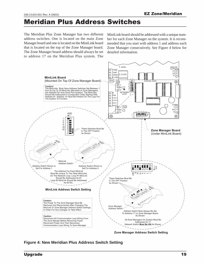
Meridian Plus Address Switches
Figure 4: New Meridian Plus Address Switch Setting
The Meridian Plus Zone Manager has two differentaddress switches. One is located on the main ZoneManager board and one is located on the MiniLink boardthat is located on the top of the Zone Manager board.The Zone Manager board address should always be setto address 17 on the Meridian Plus system. The
MiniLink board should be addressed with a unique num-ber for each Zone Manager on the system. It is recom-mended that you start with address 1 and address eachZone Manager consecutively. See Figure 4 below fordetailed information.
EZ Zone/Meridian
20 Upgrade
036-21423-001 Rev. A (0602)
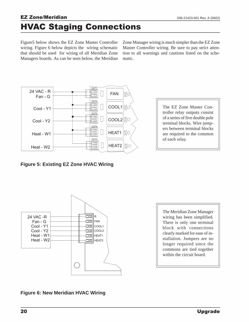
HVAC Staging Connections
Figure 6: New Meridian HVAC Wiring
Figure5 below shows the EZ Zone Master Controllerwiring. Figure 6 below depicts the wiring schematicthat should be used for wiring of all Meridian ZoneManagers boards. As can be seen below, the Meridian
OUT1
OUT2
OUT3
OUT4
OUT5
FAN
COOL1
COOL2
HEAT1
HEAT2
24 VAC - R
Fan - G
Cool - Y1
Cool - Y2
Heat - W1
Heat - W2
HEAT2
HEAT1
COOL2
COOL1
FAN
R
Fan - GCool - Y1Cool - Y2Heat - W1Heat - W2
24 VAC -R
Figure 5: Existing EZ Zone HVAC Wiring
The EZ Zone Master Con-troller relay outputs consistof a series of five double poleterminal blocks. Wire jump-ers between terminal blocksare required to the commonof each relay.
The Meridian Zone Managerwiring has been simplified.There is only one terminalblock with connectionsclearly marked for ease of in-stallation. Jumpers are nolonger required since thecommons are tied togetherwithin the circuit board.
Zone Manager wiring is much simpler than the EZ ZoneMaster Controller wiring. Be sure to pay strict atten-tion to all warnings and cautions listed on the sche-matic.
EZ Zone/Meridian
Upgrade 21
036-21423-001 Rev. A (0602)
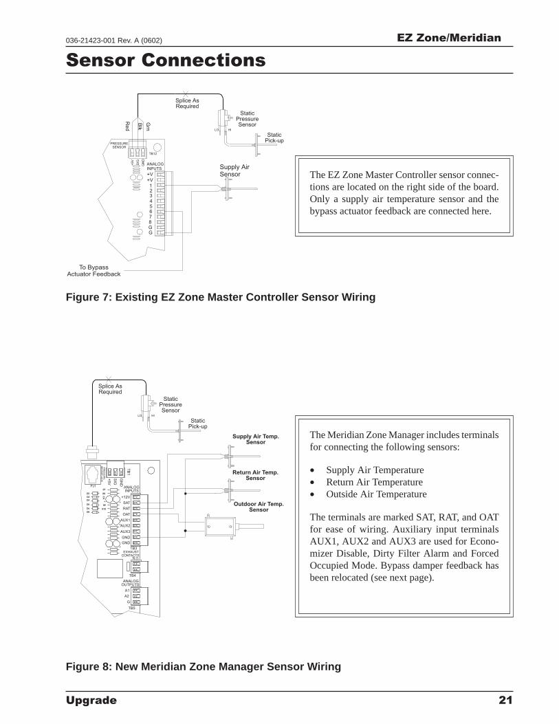
Sensor Connections
Figure 8: New Meridian Zone Manager Sensor Wiring
ANALOGINPUTS
+V
+V12345678GG
PRESSURESENSOR
+5V
SIG
GN
D
TB12
StaticPick-up
StaticPressureSensor
Splice AsRequired
LO HI
Red
Blk
Grn
Supply AirSensor
To BypassActuator Feedback
++
+ +
R9
R10
C4
R8
AUX1
ANALOGOUTPUTS
A2
G
TB5
TB4
TB3
A1
N.O.CONTACTS
EXHAUST
GND
GND
AUX3
AUX2
D3
D4
D5
D6
D8
D2
PR
ES
SU
RE
SE
NS
OR
JA
CK
+5V
R7 INPUTS
OAT
RAT
+12V
SAT
ANALOG
GN
D
SIG
TB
1
PJ1
Return Air Temp.Sensor
Supply Air Temp.Sensor
Outdoor Air Temp.Sensor
StaticPick-up
StaticPressureSensor
Splice AsRequired
LO HI
Figure 7: Existing EZ Zone Master Controller Sensor Wiring
The EZ Zone Master Controller sensor connec-tions are located on the right side of the board.Only a supply air temperature sensor and thebypass actuator feedback are connected here.
The Meridian Zone Manager includes terminalsfor connecting the following sensors:
• Supply Air Temperature• Return Air Temperature• Outside Air Temperature
The terminals are marked SAT, RAT, and OATfor ease of wiring. Auxiliary input terminalsAUX1, AUX2 and AUX3 are used for Econo-mizer Disable, Dirty Filter Alarm and ForcedOccupied Mode. Bypass damper feedback hasbeen relocated (see next page).
EZ Zone/Meridian
22 Upgrade
036-21423-001 Rev. A (0602)
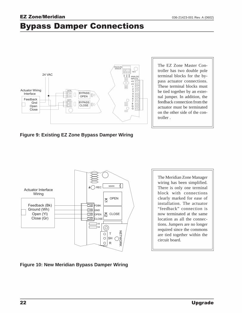
Figure 10: New Meridian Bypass Damper Wiring
ANALOGINPUTS
+V
+V12345678GG
PRESSURESENSOR
+5V
SIG
GN
D
TB12
OUT6
OUT7
BYPASS
OPEN
BYPASSCLOSE
FeedbackGnd
OpenClose
Actuator WiringInterface
24 VAC
V4
V3
REC
CLOSE
OPENK1
K2
NE
TW
OR
K
SH
R
T
NE5090
FDBK
GND
OPEN
CLOSE
Feedback (Bk)Ground (Wh)
Open (Yl)
Close (Gr)
Actuator InterfaceWiring
Figure 9: Existing EZ Zone Bypass Damper Wiring
The EZ Zone Master Con-troller has two double poleterminal blocks for the by-pass actuator connections.These terminal blocks mustbe tied together by an exter-nal jumper. In addition, thefeedback connection from theactuator must be terminatedon the other side of the con-troller .
The Meridian Zone Managerwiring has been simplified.There is only one terminalblock with connectionsclearly marked for ease ofinstallation. The actuator“feedback” connection isnow terminated at the samelocation as all the connec-tions. Jumpers are no longerrequired since the commonsare tied together within thecircuit board.
Bypass Damper Connections
EZ Zone/Meridian
Upgrade 23
036-21423-001 Rev. A (0602)
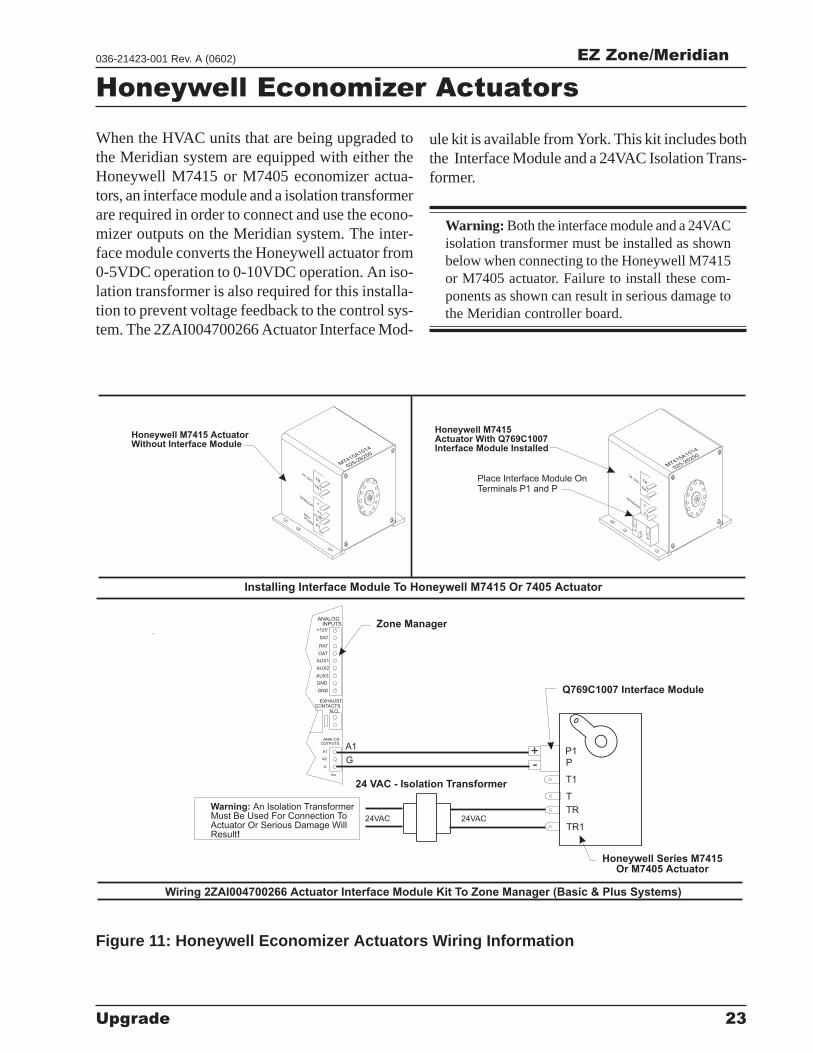
Honeywell Economizer Actuators
TR
T1
P
P1
24VAC24VAC
Zone Manager
Wiring 2ZAI004700266 Actuator Interface Module Kit To Zone Manager (Basic & Plus Systems)
Installing Interface Module To Honeywell M7415 Or 7405 Actuator
Q769C1007 Interface Module
Warning:
!
An Isolation TransformerMust Be Used For Connection ToActuator Or Serious Damage WillResult
+
TR1
T
-
A1
G
TB2
A2
G
OUTPUTSANALOG
A1
N.O.CONTACTS
EXHAUST
AUX3
GND
GND
AUX2
AUX1
ANALOG
SAT
OAT
RAT
INPUTS+12V
Honeywell Series M7415Or M7405 Actuator
24VA
C
24VA
C
T1 T1
TR TR
T T
P
P1
TR1
TR1
SEN
SO
R
SEN
SO
R
MINPO
SN
M7415A1014
025-26250
M7415A1014
025-26250
24 VAC - Isolation Transformer
Honeywell M7415 ActuatorWithout Interface Module
Honeywell M7415Actuator With Q769C1007Interface Module Installed
Place Interface Module OnTerminals P1 and P
Figure 11: Honeywell Economizer Actuators Wiring Information
When the HVAC units that are being upgraded tothe Meridian system are equipped with either theHoneywell M7415 or M7405 economizer actua-tors, an interface module and a isolation transformerare required in order to connect and use the econo-mizer outputs on the Meridian system. The inter-face module converts the Honeywell actuator from0-5VDC operation to 0-10VDC operation. An iso-lation transformer is also required for this installa-tion to prevent voltage feedback to the control sys-tem. The 2ZAI004700266 Actuator Interface Mod-
ule kit is available from York. This kit includes boththe Interface Module and a 24VAC Isolation Trans-former.
Warning: Both the interface module and a 24VACisolation transformer must be installed as shownbelow when connecting to the Honeywell M7415or M7405 actuator. Failure to install these com-ponents as shown can result in serious damage tothe Meridian controller board.
EZ Zone/Meridian
24 Upgrade
036-21423-001 Rev. A (0602)
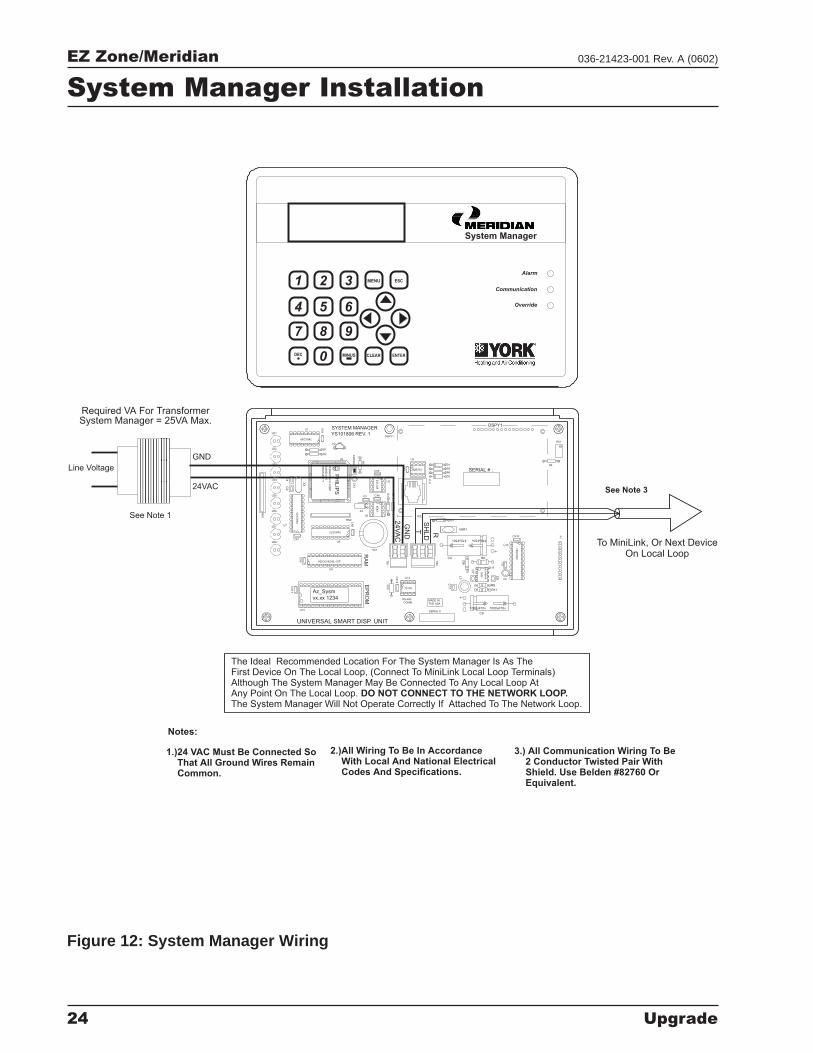
The Ideal Recommended Location For The System Manager Is As TheFirst Device On The Local Loop, (Connect To MiniLink Local Loop Terminals)Although The System Manager May Be Connected To Any Local Loop AtAny Point On The Local Loop.The System Manager Will Not Operate Correctly If Attached To The Network Loop.
DO NOT CONNECT TO THE NETWORK LOOP.
Notes:
1.)24 VAC Must Be Connected SoThat All Ground Wires RemainCommon.
2.)All Wiring To Be In AccordanceWith Local And National ElectricalCodes And Specifications.
3.) All Communication Wiring To Be2 Conductor Twisted Pair WithShield. Use Belden #82760 OrEquivalent.
System Manager
654
DEC
7
MINUS0 CLEAR
98
1 32 MENU
Override
Communication
ENTER
ESC
Alarm
To MiniLink, Or Next DeviceOn Local Loop
Line Voltage
See Note 1
See Note 324VAC
GND
Required VA For TransformerSystem Manager = 25VA Max.
MADE IN
THE USA
EP
RO
M
1000uF10v
YS101806 REV. 1
DSPY1
UNIVERSAL SMART DISP. UNIT
SYSTEM MANAGER
SERIAL # :
U13 SERIAL #1000uF10v
C9
470uF50v
D2
PC
B8
0C
55
2-5
-16
WP
44
28
60
=2
/5
DfD
97
22
V7
Y
PH
ILIP
S
CX
13
LD8
CX
9
Az_Sysm
vx.xx 1234
V62C518256L-70P
U9
U8
LD7
RN
1
LD6
U7
CX7
74
HC
57
3
LD5
LD4
74HC573
CX
8
RN2
X2
CX
4
470uF50v
TB
2
GN
D
24
VA
C
R1
0 75176
RS-485
COMM
U12
CX
12
RA
M
SC1
T
TB
1
SH
LD
C7
C11
L1
C4
R
D6
85
83
U6
CX6C3
D3
24
C1
28
U5
R7
VAR1
D4
PJ1
R3
U1
74HC259
LD3
LD2
LD1
R2
R1
EW
DO
G
PH
ILIP
S
U3
U2
CX
1
82B715CX5
CX
3
U3
DSPY1
R5
D1
R6
MC
34
06
4A
C6
R11
99
36 C
8
R9
U10
U11
R8
R12
C5
74
HC
92
3
CX10
P1
R4
RV1
C2
C1
X1
Figure 12: System Manager Wiring
System Manager Installation
EZ Zone/Meridian
Upgrade 25
036-21423-001 Rev. A (0602)
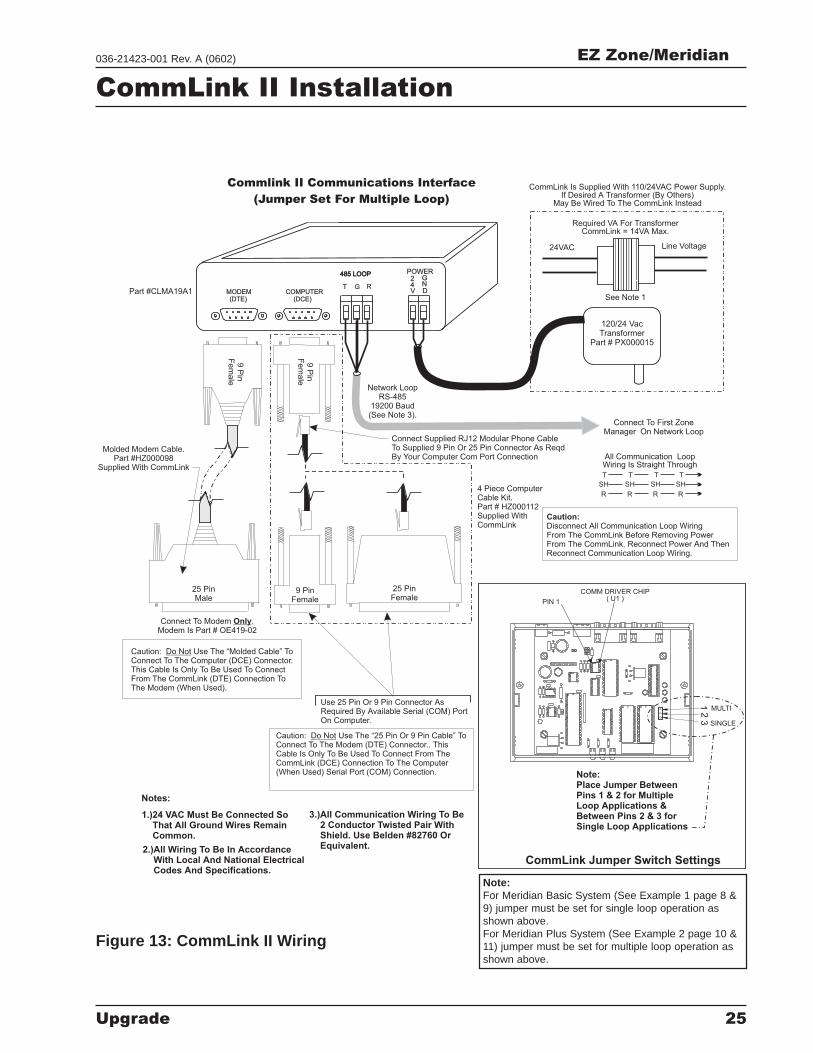
Commlink II Communications Interface
(Jumper Set For Multiple Loop)
Caution: Use The “Molded Cable” ToConnect To The Computer (DCE) Connector.This Cable Is Only To Be Used To ConnectFrom The CommLink (DTE) Connection ToThe Modem (When Used).
Do Not
Caution:Disconnect All Communication Loop WiringFrom The CommLink Before Removing PowerFrom The CommLink. Reconnect Power And ThenReconnect Communication Loop Wiring.
Use 25 Pin Or 9 Pin Connector AsRequired By Available Serial (COM) PortOn Computer.
Caution: Use The “25 Pin Or 9 Pin Cable” ToConnect To The Modem (DTE) Connector.. ThisCable Is Only To Be Used To Connect From TheCommLink (DCE) Connection To The Computer
Serial Port (COM) Connection.
Do Not
(When Used) Note:Place Jumper BetweenPins 1 & 2 for MultipleLoop Applications &Between Pins 2 & 3 forSingle Loop Applications
COMM DRIVER CHIP( U1 )PIN 1
MULTI
SINGLE
12
3
CommLink Jumper Switch Settings
Notes:
R
SH
T
R
SH
T
R
SH
T
R
SH
T
All Communication LoopWiring Is Straight Through
Connect To First ZoneManager On Network Loop
Network LoopRS-485
19200 Baud(See Note 3).
Line Voltage
See Note 1
24VAC
Required VA For TransformerCommLink = 14VA Max.
CommLink Is Supplied With 110/24VAC Power Supply.If Desired A Transformer (By Others)
May Be Wired To The CommLink Instead
Molded Modem Cable.Part #HZ000098
Supplied With CommLink
(DTE)MODEM
485 LOOP485 LOOP
COMPUTER(DCE)
GT R
G2
V4
DN
POWER
4 Piece ComputerCable Kit.Part # HZ000112Supplied WithCommLink
Connect To Modem .Modem Is Part # OE419-02
Only
9P
inF
em
ale
9 PinFemale
25 PinFemale
9P
inF
em
ale
120/24 VacTransformer
Part # PX000015
25 PinMale
Part #CLMA19A1
Connect Supplied RJ12 Modular Phone CableTo Supplied 9 Pin Or 25 Pin Connector As ReqdBy Your Computer Com Port Connection
1.)24 VAC Must Be Connected SoThat All Ground Wires RemainCommon.
2.)All Wiring To Be In AccordanceWith Local And National ElectricalCodes And Specifications.
3.)All Communication Wiring To Be2 Conductor Twisted Pair WithShield. Use Belden #82760 OrEquivalent.
Figure 13: CommLink II Wiring
CommLink II Installation
Note:For Meridian Basic System (See Example 1 page 8 &9) jumper must be set for single loop operation asshown above.For Meridian Plus System (See Example 2 page 10 &11) jumper must be set for multiple loop operation asshown above.
EZ Zone/Meridian
26 Upgrade
036-21423-001 Rev. A (0602)
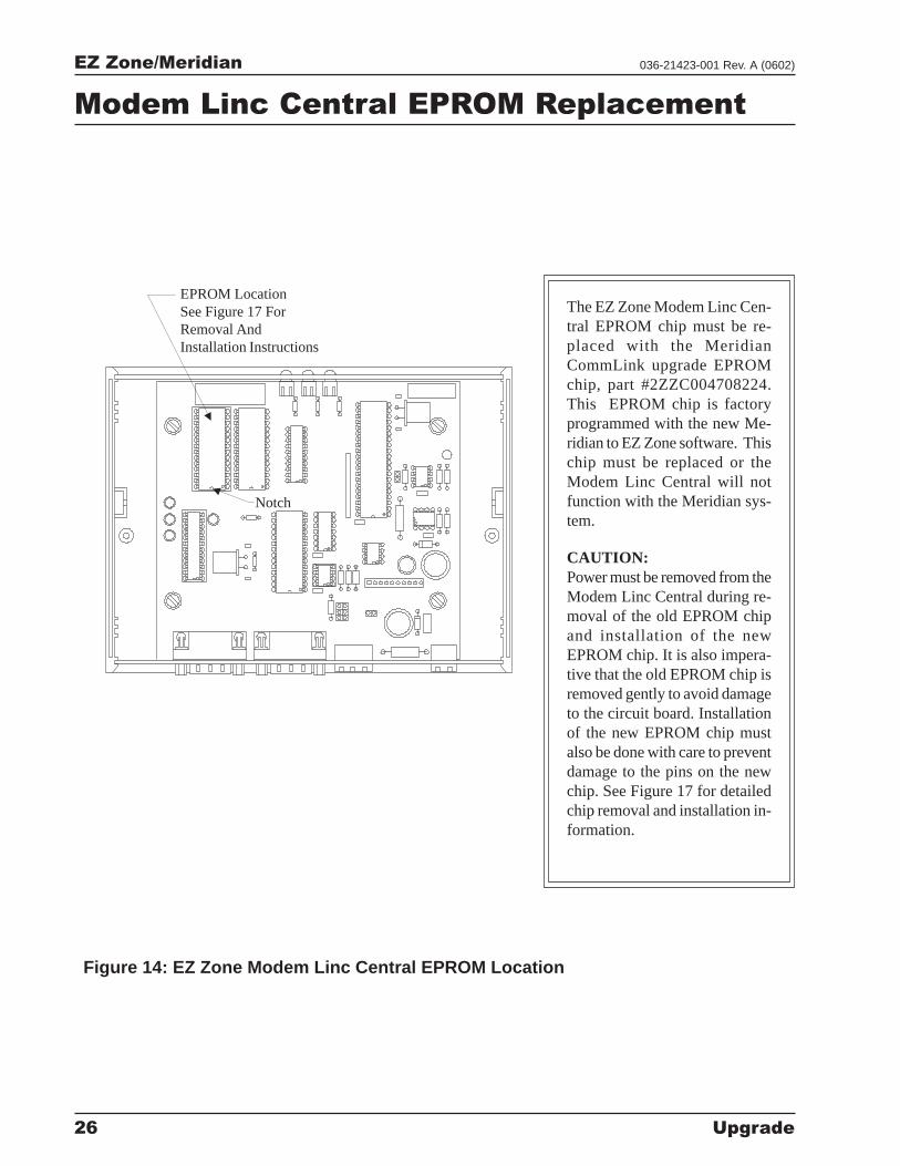
EPROM LocationSee Figure 17 ForRemoval AndInstallation Instructions
Figure 14: EZ Zone Modem Linc Central EPROM Location
Modem Linc Central EPROM Replacement
The EZ Zone Modem Linc Cen-tral EPROM chip must be re-placed with the MeridianCommLink upgrade EPROMchip, part #2ZZC004708224.This EPROM chip is factoryprogrammed with the new Me-ridian to EZ Zone software. Thischip must be replaced or theModem Linc Central will notfunction with the Meridian sys-tem.
CAUTION:Power must be removed from theModem Linc Central during re-moval of the old EPROM chipand installation of the newEPROM chip. It is also impera-tive that the old EPROM chip isremoved gently to avoid damageto the circuit board. Installationof the new EPROM chip mustalso be done with care to preventdamage to the pins on the newchip. See Figure 17 for detailedchip removal and installation in-formation.
Notch
EZ Zone/Meridian
Upgrade 27
036-21423-001 Rev. A (0602)
LO
OP
NE
TW
OR
K
T
SH
R
24VAC
GND
T
SH
R
32
16
8
4
1
2
1
2
3
4
7
5
6
8
OFF>
Ro
cke
rD
ow
n
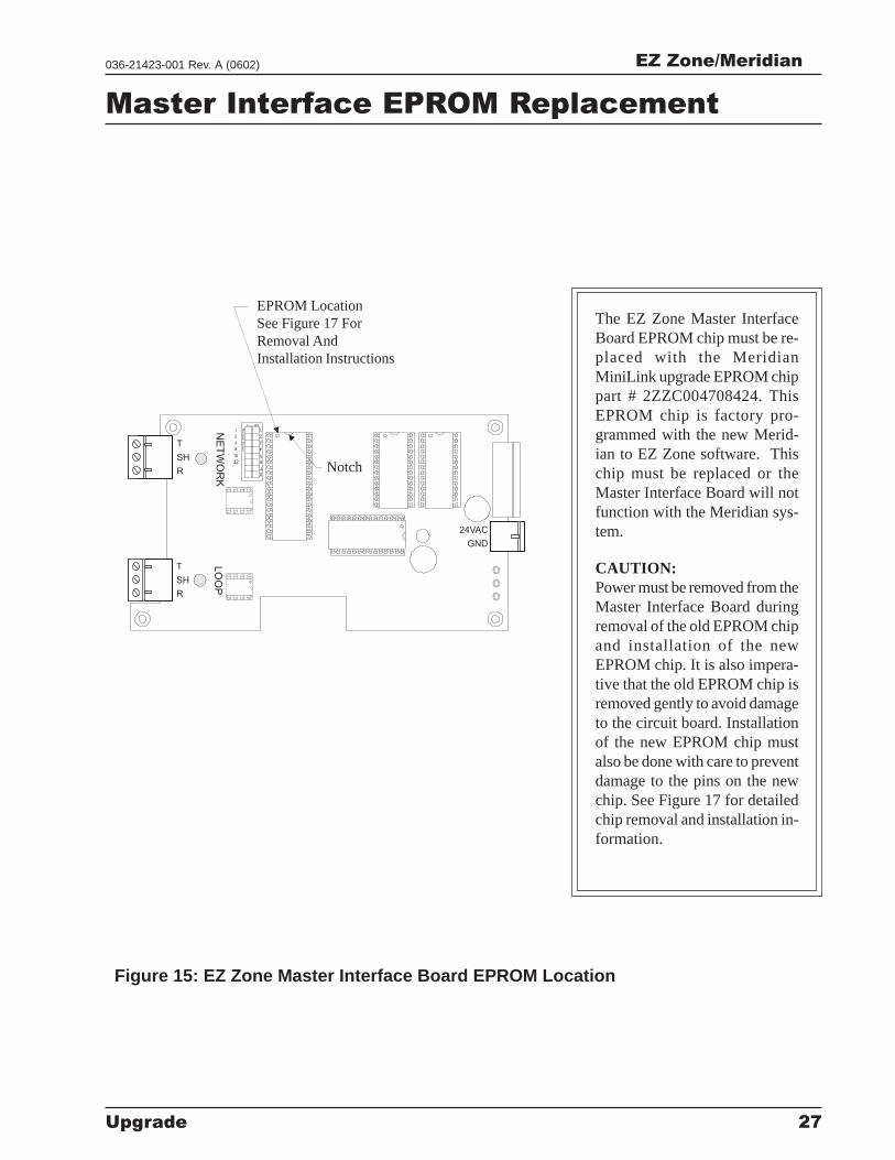
EPROM LocationSee Figure 17 ForRemoval AndInstallation Instructions
Figure 15: EZ Zone Master Interface Board EPROM Location
The EZ Zone Master InterfaceBoard EPROM chip must be re-placed with the MeridianMiniLink upgrade EPROM chippart # 2ZZC004708424. ThisEPROM chip is factory pro-grammed with the new Merid-ian to EZ Zone software. Thischip must be replaced or theMaster Interface Board will notfunction with the Meridian sys-tem.
CAUTION:Power must be removed from theMaster Interface Board duringremoval of the old EPROM chipand installation of the newEPROM chip. It is also impera-tive that the old EPROM chip isremoved gently to avoid damageto the circuit board. Installationof the new EPROM chip mustalso be done with care to preventdamage to the pins on the newchip. See Figure 17 for detailedchip removal and installation in-formation.
Master Interface EPROM Replacement
Notch
EZ Zone/Meridian
28 Upgrade
036-21423-001 Rev. A (0602)
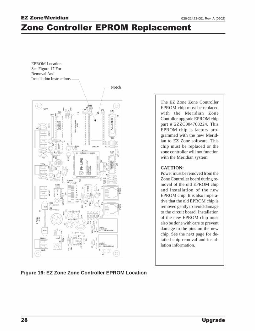
Figure 16: EZ Zone Zone Controller EPROM Location
Zone Controller EPROM Replacement
CX
6
SW
1
U10
75176
EX
PA
NS
ION
Q3
Q2
D3
VR
17824
GND
24VAC
M
7824CT
MC34064A
9936
R17
R16
U7
C7
R15
PO
WE
RR
21
RE
V.2
YS
101
562
MDL
F1
250D4
R26
LD3
L1
SCAN REC
R12
C6
R11
TOKEN
NET
LD
2
32
R14
R13
R100
LD
1
C5
D1
K1
V2
24VDCCONTACT:UL / CSA 5A250VAC
K2
D2
AC
TU
AT
OR
24VDCCONTACT:UL / CSA 5A250VAC
R10
R9
PJ2
V1
C4
74H
C573N
B31920P
S
TC
U3
2K
2V
9936
MS
6264L-7
0P
C
EPROM
VR
EF
AD
J
R23
C10
PC
B8
0C
55
2-5
-16
WP
50
06
50
=1
/3D
FD
99
40
SM
PH
ILIP
S
EW
DO
G
CO
MM
D7
CX10
R25
R2
8
T'STAT U
11
C15
R2
0
C11
R24
8
16
2
4
ADDRESS ADD
1 U6
93C
46
U5
R1
9
PH
ILIP
S
U9CX9
R32
D5
C14
P.U.
R22
C13
LM
C6
62
R2
7
D5
RAM
C9
C8
80C552
CX
5P
J1
C3
R8
R7
R5
R6
R4
C2
C1
X1 74H
C259
B31920P
S
U2
R1
R2
R3
CX2
Q1
16L8
32K
R34FLOW
U8RN1
CX8 U4
R18 CX4
8KRAM
U3
CX3
U1
CX1
The EZ Zone Zone ControllerEPROM chip must be replacedwith the Meridian ZoneContoller upgrade EPROM chippart # 2ZZC004708224. ThisEPROM chip is factory pro-grammed with the new Merid-ian to EZ Zone software. Thischip must be replaced or thezone controller will not functionwith the Meridian system.
CAUTION:Power must be removed from theZone Controller board during re-moval of the old EPROM chipand installation of the newEPROM chip. It is also impera-tive that the old EPROM chip isremoved gently to avoid damageto the circuit board. Installationof the new EPROM chip mustalso be done with care to preventdamage to the pins on the newchip. See the next page for de-tailed chip removal and instal-lation information.
EPROM LocationSee Figure 17 ForRemoval AndInstallation Instructions
Notch
EZ Zone/Meridian
Upgrade 29
036-21423-001 Rev. A (0602)
EPROM Installation Procedures
Small FlatheadScrewdriver
Chip
Chip
Printed CircuitBoard
Printed CircuitBoard
Printed CircuitBoard
Chip
WARNING!
Direction Of Pull
Notch
Dot
Pin1
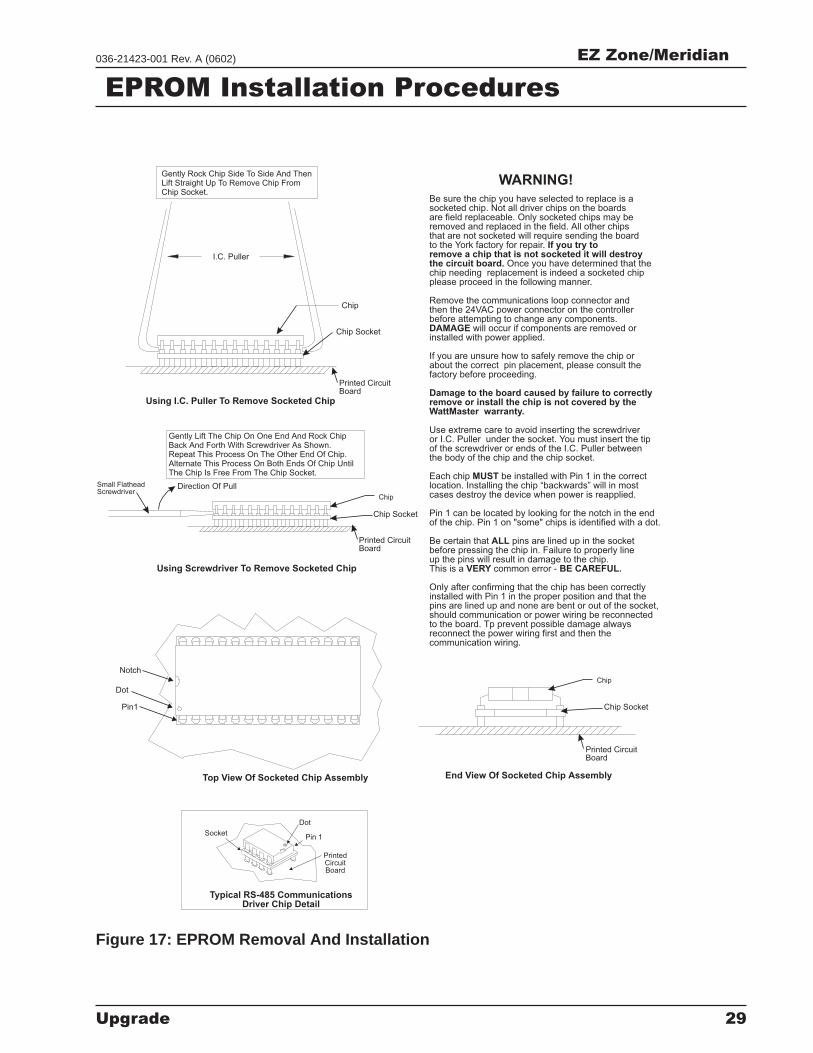
Be sure the chip you have selected to replace is asocketed chip. Not all driver chips on the boardsare field replaceable. Only socketed chips may beremoved and replaced in the field. All other chipsthat are not socketed will require sending the boardto the York factory for repair.
Once you have determined that thechip needing replacement is indeed a socketed chipplease proceed in the following manner.
Remove the communications loop connector andthen the 24VAC power connector on the controllerbefore attempting to change any components.
will occur if components are removed orinstalled with power applied.
If you are unsure how to safely remove the chip orabout the correct pin placement, please consult thefactory before proceeding.
Use extreme care to avoid inserting the screwdriveror I.C. Puller under the socket. You must insert the tipof the screwdriver or ends of the I.C. Puller betweenthe body of the chip and the chip socket.
Each chip be installed with Pin 1 in the correctlocation. Installing the chip “backwards” will in mostcases destroy the device when power is reapplied.
Pin 1 can be located by looking for the notch in the endof the chip. Pin 1 on "some" chips is identified with a dot.
Be certain that pins are lined up in the socketbefore pressing the chip in. Failure to properly lineup the pins will result in damage to the chip.This is a common error -
Only after confirming that the chip has been correctlyinstalled with Pin 1 in the proper position and that thepins are lined up and none are bent or out of the socket,should communication or power wiring be reconnectedto the board. Tp prevent possible damage alwaysreconnect the power wiring first and then thecommunication wiring.
If you try toremove a chip that is not socketed it will destroythe circuit board.
DAMAGE
Damage to the board caused by failure to correctlyremove or install the chip is not covered by theWattMaster warranty.
MUST
ALL
VERY BE CAREFUL.
Using I.C. Puller To Remove Socketed Chip
Using Screwdriver To Remove Socketed Chip
End View Of Socketed Chip AssemblyTop View Of Socketed Chip Assembly
I.C. Puller
Chip Socket
Chip Socket
Chip Socket
Gently Rock Chip Side To Side And ThenLift Straight Up To Remove Chip FromChip Socket.
Gently Lift The Chip On One End And Rock ChipBack And Forth With Screwdriver As Shown.Repeat This Process On The Other End Of Chip.Alternate This Process On Both Ends Of Chip UntilThe Chip Is Free From The Chip Socket.
Pin 1
Dot
Socket
PrintedCircuitBoard
Typical RS-485 CommunicationsDriver Chip Detail
Figure 17: EPROM Removal And Installation
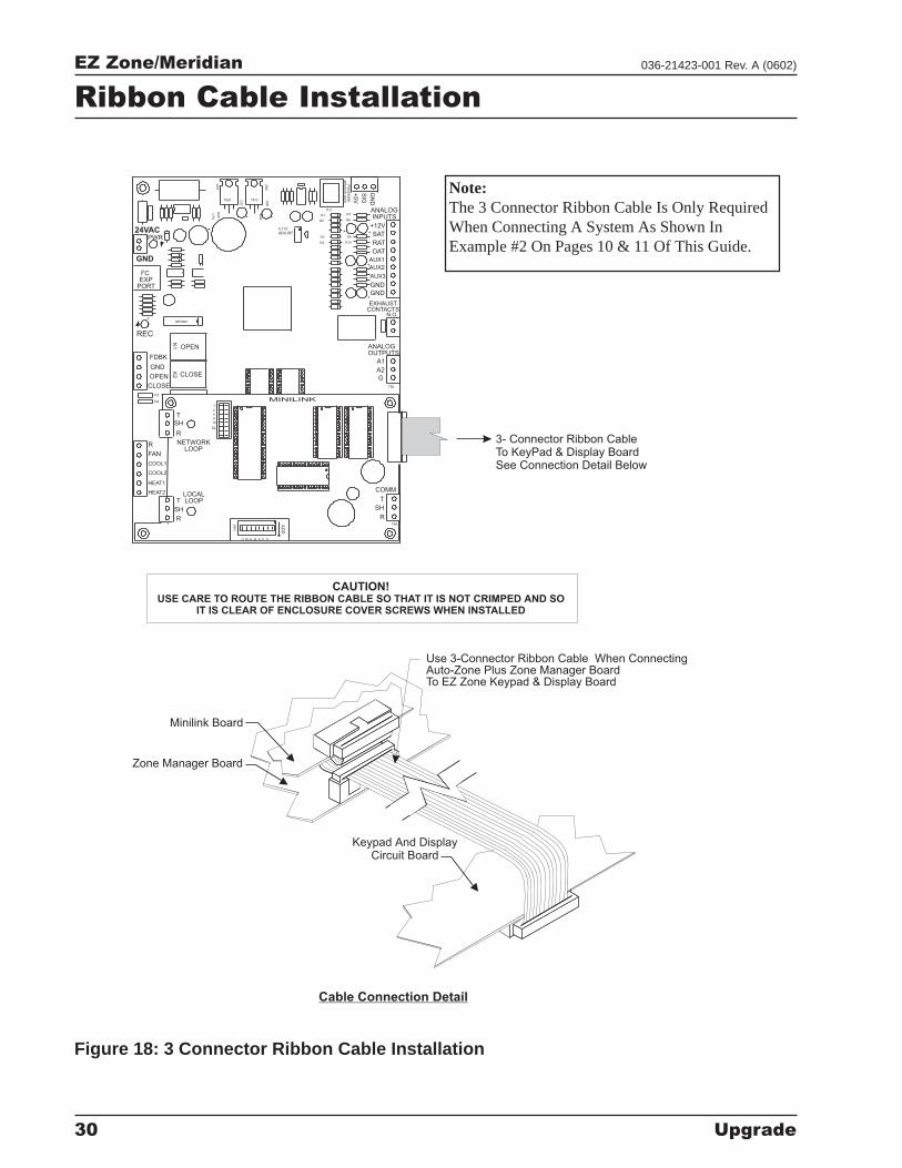
EZ Zone/Meridian
30 Upgrade
036-21423-001 Rev. A (0602)
Minilink Board
Zone Manager Board
Keypad And DisplayCircuit Board
3- Connector Ribbon CableTo KeyPad & Display BoardSee Connection Detail Below
Cable Connection Detail
+
+
++
+
++
+ +
HEAT2
HEAT1
COOL2
COOL1
FAN
R
2
8C
SW
1
16AB 24
AD
D
LOCALLOOPT
SH
RTB3
COMM
T
SH
R
32
16
8
4
1
2
MINILINK
R9
R10
R8
I CEXP
PORT
PWR
V4
V3
CLOSE
OPEN
FDBK
REC
GND
GND
24VAC
AUX1
OPEN
K1
NETWORKLOOP
SH
R
T
CLOSE
K2
NE5090
ANALOGOUTPUTS
A2
G
TB2
A1
N.O.
EXHAUSTCONTACTS
GND
GND
AUX3
AUX2
7824
D25
U14
VR
3
R40
ADJUST5.11V
C27
7812 C26
VR
2
D1
D3
D4
D2
PJ1
PR
ES
SU
RE
SE
NS
OR
JA
CK
+5V
R7
OAT
RAT
+12V
SAT
ANALOGINPUTS
GN
D
SIG
Use 3-Connector Ribbon Cable When ConnectingAuto-Zone Plus Zone Manager BoardTo EZ Zone Keypad & Display Board
USE CARE TO ROUTE THE RIBBON CABLE SO THAT IT IS NOT CRIMPED AND SOIT IS CLEAR OF ENCLOSURE COVER SCREWS WHEN INSTALLED
CAUTION!
Figure 18: 3 Connector Ribbon Cable Installation
Note:The 3 Connector Ribbon Cable Is Only RequiredWhen Connecting A System As Shown InExample #2 On Pages 10 & 11 Of This Guide.
Ribbon Cable Installation
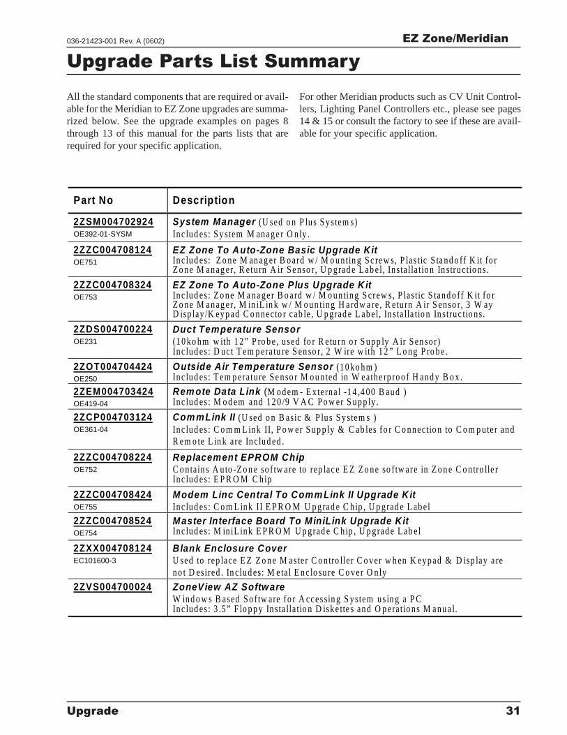
EZ Zone/Meridian
Upgrade 31
036-21423-001 Rev. A (0602)
Upgrade Parts List Summary
All the standard components that are required or avail-able for the Meridian to EZ Zone upgrades are summa-rized below. See the upgrade examples on pages 8through 13 of this manual for the parts lists that arerequired for your specific application.
For other Meridian products such as CV Unit Control-lers, Lighting Panel Controllers etc., please see pages14 & 15 or consult the factory to see if these are avail-able for your specific application.
Part No Description
2ZSM004702924OE392-01-SYSM
System Manager (U sed o n P lus S y s tem s)Inc lud es : S y stem M anage r O n ly .
2ZZC004708124OE751
EZ Zone To Auto-Zone Basic Upgrade KitInc lud es : Z o ne M an ag er B o ard w / M o un tin g S c re w s, P las tic S ta nd o ff K it fo rZ o ne M anag er, R etu rn A ir S enso r, U p grad e L ab e l, In s ta lla tio n In struc tio ns.
2ZZC004708324OE753
EZ Zone To Auto-Zone Plus Upgrade K itInc lud es : Z o ne M a na ge r B o ard w / M o un ting S crew s, P lastic S tand o f f K it fo rZ o ne M anag er, M in iL in k w / M o un ting H ard w a re , R etu rn A ir S enso r, 3 W ayD isp lay /K ey p ad C o nnecto r cab le , U p grad e L ab el, In sta lla tio n In struc tio ns.
2ZDS004700224OE231
Duct Temperature Sensor(1 0 ko hm w ith 1 2 ” P ro b e , u sed fo r R etu rn o r S up p ly A ir S en so r)Inc lud es : D uct T em p era tu re S en so r, 2 W ire w ith 1 2 ” L o ng P ro b e .
2ZOT004704424OE250
Outside Air Temperature Sensor (1 0 ko hm )Inc lud es : T em p era tu re S e nso r M o u n ted in W eathe rp ro o f H and y B o x .
2ZEM004703424OE419-04
Rem ote Data Link (M od em - E x terna l -1 4 ,4 00 B aud )Inc lud es : M o d em and 12 0 /9 V A C P o w er S up p ly .
2ZCP004703124OE361-04
Com mLink II (U sed o n B asic & P lus S y stem s )Inc lud es : C o m m L ink II, P o w er S up p ly & C ab les fo r C o nnectio n to C o m p u ter andR em o te L in k a re In c lud ed .
2ZZC004708224OE752
Replacement EPROM ChipC o ntain s A u to -Z o n e so f tw are to rep lac e E Z Z o ne so ftw are in Z o n e C o n tro lle rInc lud es : E P R O M C hip
2ZZC004708424OE755
Modem Linc Central To Comm Link II Upgrade K itInc lud es : C o m L ink II E P R O M U p grad e C h ip , U p grad e L ab el
2ZZC004708524OE754
Master Interface Board To MiniLink Upgrade KitInc lud es : M in iL ink E P R O M U p grad e C h ip , U p grad e L ab el
2ZXX004708124EC101600-3
Blank Enclosure CoverU sed to rep lace E Z Z o n e M as ter C o n tro ller C o ver w h en K eyp ad & D isp lay a reno t D esired . In clud es: M e ta l E nc lo su re C o ver O n ly
2ZVS004700024 ZoneView AZ SoftwareW ind o w s B ased S o ftw are fo r A cces sin g S ystem us in g a P CInc lud es : 3 .5 ” F lo p p y Insta lla tio n D iske tte s and O p era tio ns M anua l.

Subject to change without notice. Printed in U.S.A.
Copyright by Unitary Products Group 2002. All rights reserved.
UnitaryProductsGroup
5005YorkDrive
NormanOK
73069
036-21423-001 Rev. A (0602)
Supersedes: Nothing