Embed Size (px)
Citation preview
Doc. S-RZ200SDK-451 v.1.2 August 2007 © 2007 MeshNetics
eZeeNet Software Development Kit
for RZ200 1.1
User’s Guide

E Z E E N E T S O F T W A R E D E V E L O P M E N T K I T F O R R Z 2 0 0 1 . 1 U S E R ’ S G U I D E
© 2007 MeshNetics. All rights reserved.
No part of the contents of this manual may be transmitted or reproduced in any form or by any means without the written permission of MeshNetics.
Disclaimer
MeshNetics believes that all information is correct and accurate at the time of issue. MeshNetics reserves the right to make changes to this product without prior notice. Please visit MeshNetics website for the latest available version.
MeshNetics does not assume any responsibility for the use of the described product or convey any license under its patent rights.
Trademarks
MeshNetics®, ZigBit, eZeeNet, ZigBeeNet, SensiLink, as well as MeshNetics and ZigBit logos are trademarks of LuxLabs Ltd., dba MeshNetics.
All other product names, trade names, trademarks, logos or service names are the property of their respective owners.
Development Support
Software customization services can be provided on terms and conditions mutually agreed by MeshNetics and end-user.
Contact Information
MeshNetics
9 Dmitrovskoye Shosse, Moscow 127434, Russia
Tel: +7 (495) 725 8125
Office hours: 8:00am – 5:00pm (Central European Time)
Fax: +7 (495) 725 8116
E-mail: [email protected]
www.meshnetics.com
© 2007 MeshNetics Page 2/32

E Z E E N E T S O F T W A R E D E V E L O P M E N T K I T F O R R Z 2 0 0 1 . 1 U S E R ’ S G U I D E
Table of Contents
1. Introduction...................................................... 6 Intended Audience and Purpose............................... 6 Safety and Precautions ............................................. 6 Related documents.................................................... 6 Abbreviations and Acronyms .................................... 7
2. eZeeNet Software Development Kit Overview...................................................................... 8 2.1. ATAVRRZ200 Set ..................................................... 8
2.1.1. Z-Link RCB.................................................... 8 2.1.2. Display Board ................................................ 9
2.2. eZeeNet Software.................................................... 10 3. Getting Started ..............................................13 3.1. RZ200 Hardware Assembly.................................... 13 3.2. PC Software Installation .......................................... 14 4. WSN Demo Application ...............................15 4.1. Overview .................................................................. 15 4.2. Programming the Boards ........................................ 15 4.3. Setting up WSN Demo Application......................... 17 4.4. WSN Monitor Lite..................................................... 19 4.5. Running WSN Demo............................................... 21
4.5.1. Starting WSN Demo on RZ200 .................. 21 4.5.2. Using the Menu ........................................... 23 4.5.3. Resetting a Node......................................... 23 4.5.4. Changing Channel Mask ............................ 24 4.5.5. Setting Up Node Timeouts.......................... 25
5. Using eZeeNet API........................................26 5.1. Sample Application Development........................... 26
5.1.1. Building the WSN Demo............................. 26 5.1.2. Building the WSN Monitor Lite.................... 29
6. Troubleshooting............................................30 Appendices ...............................................................31
Appendix A. Delivery File Set.............................. 31
© 2007 MeshNetics Page 3/32
E Z E E N E T S O F T W A R E D E V E L O P M E N T K I T F O R R Z 2 0 0 1 . 1 U S E R ’ S G U I D E
List of Figures
Figure 1. Key Components of the RCB................................. 9
Figure 2. Key Components of the Display Board................ 10
Figure 3. eZeeNet Block Diagram....................................... 11
Figure 4. RZ200 configuration for WSN Demo application 12
Figure 5. RCB Mounted on the Display Board.................... 13
Figure 6. The Display Board with splash screen................. 19
Figure 7. Network topology tree screen .............................. 20
Figure 8. Node and sensor status screen. Page 1 ............. 20
Figure 9. Node and sensor status screen. Page 2 ............. 20
Figure 10. Node and sensor status screen. Page 3 ........... 21
Figure 11. Main menu.......................................................... 21
Figure 12. RZ200 wireless sensor network assembled...... 22
Figure 13. Send command menu....................................... 23
Figure 14. Reset node menu............................................ 24
Figure 15. Entering node short address.............................. 24
Figure 16. Entering the delay value parameter................... 24
Figure 17. Setting up channel mask.................................... 24
Figure 18. Setting up node timeouts.................................... 25
© 2007 MeshNetics Page 4/32
E Z E E N E T S O F T W A R E D E V E L O P M E N T K I T F O R R Z 2 0 0 1 . 1 U S E R ’ S G U I D E
© 2007 MeshNetics Page 5/32
List of Tables
Table 1. System requirements............................................. 14
Table 2. RZ200 LED indication under WSN Demo............ 17
Table 3. RCB AVR ATmega pinouts as assigned to WSN Demo.................................................................... 18
Table 4. Delivery File Set..................................................... 31
E Z E E N E T S O F T W A R E D E V E L O P M E N T K I T F O R R Z 2 0 0 1 . 1 U S E R ’ S G U I D E
1. Introduction
Intended Audience and Purpose
This document is intended for engineers and software developers evaluating MeshNetics eZeeNet Software with WSN Demo application and Atmel RZ200 Demonstration Kit.
Safety and Precautions
The product contains electronics, which are electrically sensitive. Please take necessary precautions when using such devices. Users are encouraged to follow common guidelines to avoid electrostatic discharge by using proper grounding techniques.
Any modifications of the hardware, its components or improper use of the product can cause an uncontrolled violation of the in-band or out-band radiation levels. This can result in progressing violation of emission level limits, thus causing harmful interference.
Please check your local regulations to make sure that the product’s electromagnetic radiation level is in compliance.
Precautions
The product radiates power in the microwave band. Although the levels are considered to be low (less than 2 mW), it is reasonable to protect the operating personnel from possible harmful impact of the electromagnetic field. When the parts of the product are turned on, an operator should avoid touching the PCB antenna and the board itself. The recommended distance between an operator and antenna should be more than 20 centimeters.
The AC/DC adapter included into the product contains high voltage circuits inside. General precautions should be taken, like checking the power cord before use if boards are mains powered.
The eZeeNet Software Development Kit contains fragile components. Please handle with care.
Related documents
[1] ATAVRRZ200 Demonstration Kit. User’s Guide. Atmel Doc. 5183
http://www.atmel.com/dyn/resources/prod_documents/doc5183.pdf
[2] eZeeNet™ IEEE802.15.4/ZigBee Software. Product Datasheet. MeshNetics Doc.
M-251~02
[3] eZeeNet™ Software 1.7. eZeeNet™ API. Reference Manual. MeshNetics Doc.
P-EZN-452~02
[4] ZigBee Document 053474r14, November 03, 2006
[5] IEEE Std 802.15.4-2003 IEEE Standard for Information technology – Part 15.4
Wireless Medium Access Control (MAC) and Physical Layer (PHY) Specifications
for Low-Rate Wireless Personal Area Networks (LR-WPANs)
[6] AVR Studio. User Guide.
http://www.atmel.com/dyn/resources/prod_documents/doc2510.pdf.
[7] AVRISP mkII User Guide.
http://www.atmel.com/dyn/resources/prod_documents/AVRISPmkII_UG.pdf
[8] WinAVR User Manual – 20060125/ By Eric B. Weddington.
© 2007 MeshNetics Page 6/32

E Z E E N E T S O F T W A R E D E V E L O P M E N T K I T F O R R Z 2 0 0 1 . 1 U S E R ’ S G U I D E
Abbreviations and Acronyms
ADC Analog to Digital Converter
API Application Programming Interface
Channel Mask Channel mask is a number that defines the set of working channels.
Coordinator Within ZigBee networks, a ZigBee coordinator is responsible for starting the network and for choosing certain key network parameters. However, network may be extended with ZigBee routers.
EEPROM Electrically Erasable Programmable Read-Only Memory
End device In ZigBee networks, a ZigBee end device provides sensor data sent to a router. End device may be subject to power management restrictions, so it may remain in sleeping mode most of the time.
ESD Electrostatic Discharge
GPIO General Purpose Input/Output
GUI Graphical User Interface
HAL Hardware Abstraction Layer
IDE Integrated Development Environment
JTAG Digital interface for debugging of embedded devices. Also known as IEEE 1149.1 standard interface
LCD Liquid Crystal Display
LED Light Emitting Diode
LQI Link Quality Indicator
MAC Medium Access Control layer
MCU Microcontroller Unit
NWK Network layer
PAN ID Personal Area Network Identifier. According to ZigBee standard, it is 16-bit number which must be unique for every network operating on the same frequency.
PCB Printed Circuit Board
PHY Physical layer
RCB Radio Controller Board
RF Radio Frequency
Router In ZigBee networks, ZigBee routers transfer data and control messages through the network using a hierarchical routing strategy. The ZigBee coordinator is also responsible for routing.
RSSI Received Signal Strength Indicator
WSN Wireless Sensor Network
ZigBee Wireless networking standard targeted at low-power sensor applications
© 2007 MeshNetics Page 7/32
E Z E E N E T S O F T W A R E D E V E L O P M E N T K I T F O R R Z 2 0 0 1 . 1 U S E R ’ S G U I D E
2. eZeeNet Software Development Kit Overview
eZeeNet Software Development Kit is a flexible tool designed to evaluate the Atmel’s RZ200/RCB hardware platform (ATAVRRZ200 Demonstration Kit [1]) and to develop wireless networks applications based on the MeshNetics’ eZeeNet Software.
RZ200/RCB hardware platform is featuring AT86RF230 Radio Transceiver and AVR ATmega1281V microcontroller integrated into Radio Controller Boards. Radio Controller Boards may be programmed with WSN custom applications based on eZeeNet Software [2]. In turn, eZeeNet developed applications enable the boards as nodes in a ZigBee/ 802.15.4 wireless network [4], [5]. The boards can be configured to operate as a network coordinator, a router or an end device, by loading the corresponding firmware image.
eZeeNet Software Development Kit consists of the following parts:
1. Atmel’s ATAVRRZ200 set
• Radio Controller Boards with on-board Antenna (RCBs) • Display board • AVRISP mkII In-System Programmer • Accessories
2. eZeeNet Software & Documentation.
2.1. ATAVRRZ200 Set
2.1.1. Z-Link RCB
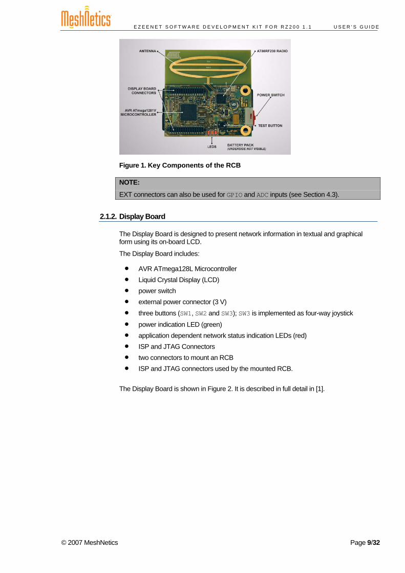
The Radio Controller Board is an integrated wireless device powered by two AA batteries. It contains:
• AT86RF230 Radio Transceiver with PCB Antenna • AVR ATmega1281V Microcontroller • power switch • test button • 3 LEDs, application dependable • 2 EXT connectors to mount RCB onto the Display Board.
The RCB is shown in Figure 1. It is described in full detail in [1].
© 2007 MeshNetics Page 8/32
E Z E E N E T S O F T W A R E D E V E L O P M E N T K I T F O R R Z 2 0 0 1 . 1 U S E R ’ S G U I D E
Figure 1. Key Components of the RCB
NOTE:
EXT connectors can also be used for GPIO and ADC inputs (see Section 4.3).
2.1.2. Display Board
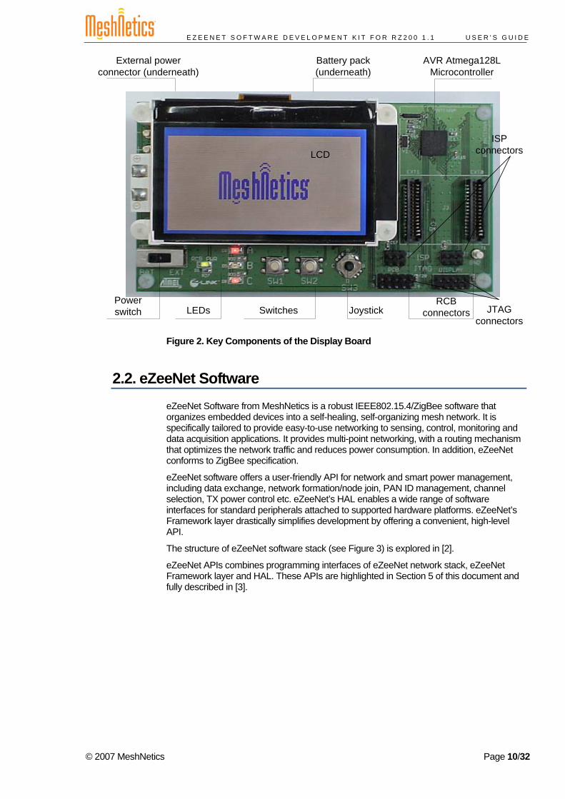
The Display Board is designed to present network information in textual and graphical form using its on-board LCD.
The Display Board includes:
• AVR ATmega128L Microcontroller • Liquid Crystal Display (LCD) • power switch • external power connector (3 V) • three buttons (SW1, SW2 and SW3); SW3 is implemented as four-way joystick
• power indication LED (green) • application dependent network status indication LEDs (red) • ISP and JTAG Connectors • two connectors to mount an RCB • ISP and JTAG connectors used by the mounted RCB.
The Display Board is shown in Figure 2. It is described in full detail in [1].
© 2007 MeshNetics Page 9/32
E Z E E N E T S O F T W A R E D E V E L O P M E N T K I T F O R R Z 2 0 0 1 . 1 U S E R ’ S G U I D E
External power connector (underneath)
AVR Atmega128L Microcontroller
SwitchesLEDs
LCD
JoystickRCB
connectors
Battery pack(underneath)
Powerswitch
ISPconnectors
JTAGconnectors
Figure 2. Key Components of the Display Board
2.2. eZeeNet Software eZeeNet Software from MeshNetics is a robust IEEE802.15.4/ZigBee software that organizes embedded devices into a self-healing, self-organizing mesh network. It is specifically tailored to provide easy-to-use networking to sensing, control, monitoring and data acquisition applications. It provides multi-point networking, with a routing mechanism that optimizes the network traffic and reduces power consumption. In addition, eZeeNet conforms to ZigBee specification.
eZeeNet software offers a user-friendly API for network and smart power management, including data exchange, network formation/node join, PAN ID management, channel selection, TX power control etc. eZeeNet’s HAL enables a wide range of software interfaces for standard peripherals attached to supported hardware platforms. eZeeNet’s Framework layer drastically simplifies development by offering a convenient, high-level API.
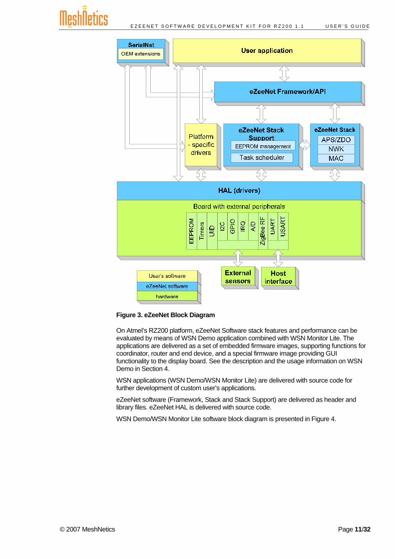
The structure of eZeeNet software stack (see Figure 3) is explored in [2].
eZeeNet APIs combines programming interfaces of eZeeNet network stack, eZeeNet Framework layer and HAL. These APIs are highlighted in Section 5 of this document and fully described in [3].
© 2007 MeshNetics Page 10/32
E Z E E N E T S O F T W A R E D E V E L O P M E N T K I T F O R R Z 2 0 0 1 . 1 U S E R ’ S G U I D E
Figure 3. eZeeNet Block Diagram
On Atmel’s RZ200 platform, eZeeNet Software stack features and performance can be evaluated by means of WSN Demo application combined with WSN Monitor Lite. The applications are delivered as a set of embedded firmware images, supporting functions for coordinator, router and end device, and a special firmware image providing GUI functionality to the display board. See the description and the usage information on WSN Demo in Section 4.
WSN applications (WSN Demo/WSN Monitor Lite) are delivered with source code for further development of custom user’s applications.
eZeeNet software (Framework, Stack and Stack Support) are delivered as header and library files. eZeeNet HAL is delivered with source code.
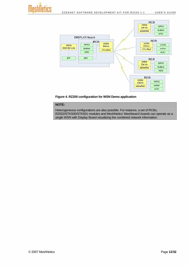
WSN Demo/WSN Monitor Lite software block diagram is presented in Figure 4.
© 2007 MeshNetics Page 11/32
E Z E E N E T S O F T W A R E D E V E L O P M E N T K I T F O R R Z 2 0 0 1 . 1 U S E R ’ S G U I D E
Figure 4. RZ200 configuration for WSN Demo application
NOTE:
Heterogeneous configurations are also possible. For instance, a set of RCBs, RZ502/STK500/STK501 modules and MeshNetics’ Meshbean2 boards can operate as a single WSN with Display Board visualizing the combined network information.
© 2007 MeshNetics Page 12/32
E Z E E N E T S O F T W A R E D E V E L O P M E N T K I T F O R R Z 2 0 0 1 . 1 U S E R ’ S G U I D E
3. Getting Started Before running WSN Demo application the boards should be assembled and programmed, following the instructions given in Section 3.1 and Section 4.2.
To run WSN Demo, see instructions in Section 4. In case of a problem, refer to Section 6.
3.1. RZ200 Hardware Assembly The Display Board is supplied with AA batteries while each of the RCBs is supplied with AAA batteries.
To assemble the RZ200 hardware, proceed as follows:
1. Make sure that the coordinator RCB and the Display Board are powered off.
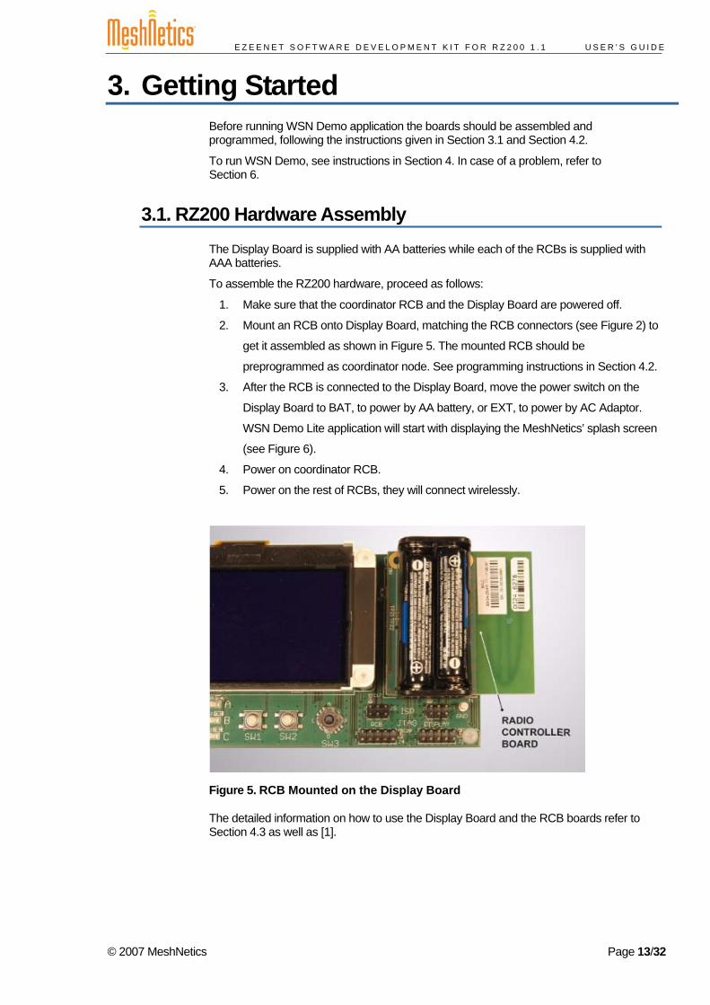
2. Mount an RCB onto Display Board, matching the RCB connectors (see Figure 2) to
get it assembled as shown in Figure 5. The mounted RCB should be
preprogrammed as coordinator node. See programming instructions in Section 4.2.
3. After the RCB is connected to the Display Board, move the power switch on the
Display Board to BAT, to power by AA battery, or EXT, to power by AC Adaptor.
WSN Demo Lite application will start with displaying the MeshNetics’ splash screen
(see Figure 6).
4. Power on coordinator RCB.
5. Power on the rest of RCBs, they will connect wirelessly.
Figure 5. RCB Mounted on the Display Board
The detailed information on how to use the Display Board and the RCB boards refer to Section 4.3 as well as [1].
© 2007 MeshNetics Page 13/32
E Z E E N E T S O F T W A R E D E V E L O P M E N T K I T F O R R Z 2 0 0 1 . 1 U S E R ’ S G U I D E
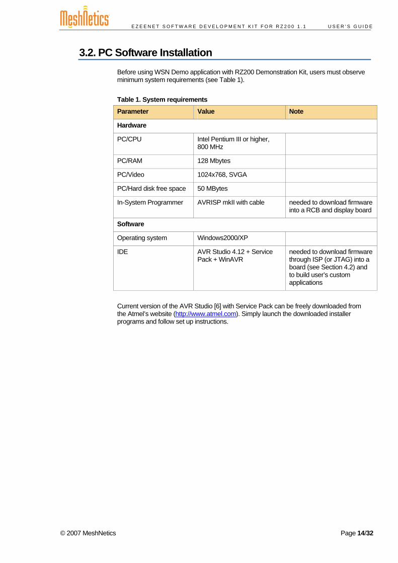
3.2. PC Software Installation Before using WSN Demo application with RZ200 Demonstration Kit, users must observe minimum system requirements (see Table 1).
Table 1. System requirements
Parameter Value Note
Hardware
PC/CPU Intel Pentium III or higher, 800 MHz
PC/RAM 128 Mbytes
PC/Video 1024x768, SVGA
PC/Hard disk free space 50 MBytes
In-System Programmer AVRISP mkII with cable needed to download firmware into a RCB and display board
Software
Operating system Windows2000/XP
IDE AVR Studio 4.12 + Service Pack + WinAVR
needed to download firmware through ISP (or JTAG) into a board (see Section 4.2) and to build user’s custom applications
Current version of the AVR Studio [6] with Service Pack can be freely downloaded from the Atmel’s website (http://www.atmel.com). Simply launch the downloaded installer programs and follow set up instructions.
© 2007 MeshNetics Page 14/32
E Z E E N E T S O F T W A R E D E V E L O P M E N T K I T F O R R Z 2 0 0 1 . 1 U S E R ’ S G U I D E
4. WSN Demo Application
4.1. Overview WSN Demo application is intended to evaluate operation of Atmel’s hardware as a part of a full-featured ZigBee network.
Due to operation of embedded WSN Demo firmware, the RCB boards are organized into a single wireless network. Periodically, end devices and routers read their onboard sensor interfaces (GPIO, ADC). These readings are then sent to coordinator node. End devices are mostly sleeping, consuming very low power, waking up only to collect and send the readings every 10 seconds. Routers send data every second. The coordinator transmits the received packets, along with its own sensor data, to the GUI (WSN Monitor Lite) application, over SPI connection between coordinator RCB and the Display Board.
Maximum network size is not restricted by eZeeNet Software; however, WSN Monitor Lite can only correctly render network topology up to 10 nodes.
The function of WSN Monitor Lite is to visualize the network topology and to display node parameters like addresses, node sensor information and the node link quality data.
Measured in dBm, RSSI reflects the link’s current condition. Actual resolution of RSSI is 3 dBm, resulting in RSSI values that are not very accurate. LQI also measures link quality and is defined within the 0...255 range. Larger values mean better link, while values closer to zero indicate poor communication conditions.
Using WSN Monitor Lite controls you can resent a node remotely and change the network channel mask and various node timeouts.
4.2. Programming the Boards All the boards can be programmed under AVR Studio using the supplied In-System Programmer, AVRISP mkII, from Atmel [7].
As an RCB has no ISP connectors it can be programmed only when it is mounted on the Display Board. Attach cable linking AVRISP mkII to the Display Board. Depending on the target use ISP connector intended to the Display Board itself or ISP connector intended to RCB (see Figure 2). Start downloading process following instructions from [6] and [7].
When programming the boards under AVR Studio you must set connection specifically for using AVRISP mkII. Namely you need to set ISP frequency. Select Tools/Program AVR/Connect from the main menu. AVRISP mkII dialog then opens. In the Board tab, check up the value in ISP Freq combo-box and select it, if necessary, making sure that it is less than 1 MHz, then press Write button.
To program RCB as coordinator, router or end device use the corresponding *.hex image files found in ./Demo/WSNDemo/ subdirectory (see notation in Table 4). Make sure all your boards are programmed with different images and no image file is used twice.
For instance, the following set may be used to build a network consisting of coordinator, 2 routers and end device:
wsndemo_rcb_c_1.hex wsndemo_rcb_r_2.hex wsndemo_rcb_r_3.hex wsndemo_rcb_e_10.hex
© 2007 MeshNetics Page 15/32
E Z E E N E T S O F T W A R E D E V E L O P M E N T K I T F O R R Z 2 0 0 1 . 1 U S E R ’ S G U I D E
NOTE:
After having been programmed, RCB board gets the unique MAC address which is encoded within the downloaded image file. This MAC address is represented by two low-order digits included in the corresponding filename.
To program the Display Board with WSN Monitor Lite use *.hex and *.eep image files from ./Demo/wsnml/ subdirectory.
When downloading the images, fuse bits should be set into the positions depending on the target board type.
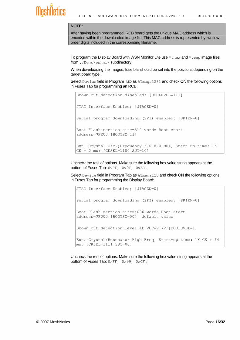
Select Device field in Program Tab as ATmega1281 and check ON the following options in Fuses Tab for programming an RCB:
Brown-out detection disabled; [BODLEVEL=111] JTAG Interface Enabled; [JTAGEN=0] Serial program downloading (SPI) enabled; [SPIEN=0] Boot Flash section size=512 words Boot start address=$FE00;[BOOTSZ=11] Ext. Crystal Osc.;Frequency 3.0-8.0 MHz; Start-up time: 1K CK + 0 ms; [CKSEL=1100 SUT=10]
Uncheck the rest of options. Make sure the following hex value string appears at the bottom of Fuses Tab: 0xFF, 0x9F, 0xEC.
Select Device field in Program Tab as ATmega128 and check ON the following options in Fuses Tab for programming the Display Board:
JTAG Interface Enabled; [JTAGEN=0] Serial program downloading (SPI) enabled; [SPIEN=0] Boot Flash section size=4096 words Boot start address=$F000;[BOOTSZ=00]; default value Brown-out detection level at VCC=2.7V;[BODLEVEL=1] Ext. Crystal/Resonator High Freq; Start-up time: 1K CK + 64 ms; [CKSEL=1111 SUT=00]
Uncheck the rest of options. Make sure the following hex value string appears at the bottom of Fuses Tab: 0xFF, 0x99, 0xCF.
© 2007 MeshNetics Page 16/32
E Z E E N E T S O F T W A R E D E V E L O P M E N T K I T F O R R Z 2 0 0 1 . 1 U S E R ’ S G U I D E
4.3. Setting up WSN Demo Application WSN Demo uses a default channel mask hardcoded in the firmware image and loaded into RCB’s flash memory. At each node’s initialization, the current channel mask is read from EEPROM.
IMPORTANT NOTE:
To store in EEPROM the default channel mask loaded to RCB flash memory during programming, RCBs must be initialized using the following sequence.
Press and hold the onboard button first. Turn power on the RCB with holding the button pressed for at least 1 second. The middle LED (D2) will flash 3 times. Next all the board LEDs will start blinking for 2 sec to indicate that the channel mask in EEPROM was accepted
To WSN Demo, do the following:
1. Make sure that both the coordinator RCB and the Display Board is powered off.
2. Mount the coordinator RCB onto the Display Board
3. Power on the coordinator node
4. Power on the rest of the nodes.
NOTE:
When running WSN Demo, channel mask can be changed at any point by sending the command from the Display Board (see Section 4.5.4). Channel mask recently issued from Display Board and received on RCB is stored permanently in RCB’s EEPROM. To restore the default channel mask in EEPROM repeat RCB reinitializing procedure described above.
The coordinator will organize the wireless network automatically. Upon starting, any node informs the network of its role. At that point all LEDs will flash once on a router, twice on an end device, and three times on a coordinator.
After joining the network, a node starts sending data to the coordinator as indicated by its LEDs.
WSN activity can be monitored in two ways:
• observing the on-board LEDs (see LED indication in Table 2) • monitoring the network topology and any node status through the LCD on the
Display Board (see Section 4.4).
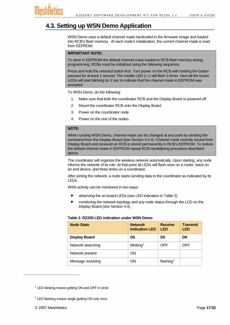
Table 2. RZ200 LED indication under WSN Demo
Node State Network Indication LED
Receive LED
Transmit LED
Display Board D6 D5 D8
Network searching blinking1 OFF OFF
Network present ON
Message receiving ON flashing2
1 LED blinking means getting ON and OFF in circle
2 LED flashing means single getting ON only once
© 2007 MeshNetics Page 17/32
E Z E E N E T S O F T W A R E D E V E L O P M E N T K I T F O R R Z 2 0 0 1 . 1 U S E R ’ S G U I D E
Node State Network Indication LED
Receive LED
Transmit LED
Message transmitting ON flashing
Coordinator/Router/End Device D3 D2 D1
Network searching blinking OFF OFF
Joined to network ON
Message receiving ON flashing
Message transmitting ON flashing
Changing channel mask blinking blinking blinking
Sleeping (for end device only) OFF OFF OFF
By default, the coordinator uses predefined PAN ID valued of A152, which is recognized by all the nodes. Changing PAN ID is not supported.
In rare cases, if radio channel is busy on the selected frequency channels the coordinator node will stay in the network searching mode. If this occurs, you should change the frequency channel by means of changing channel mask using WSN GUI.
RCB itself is not equipped with onboard sensors. Nevertheless, any RCB has two EXT connectors (see Section 2.1.1). They are bridged to GPIO and ADC pins of the AVR ATmega1281V microcontroller. GPIO and ADC pins are named by WSN Demo as shown in Table 3.
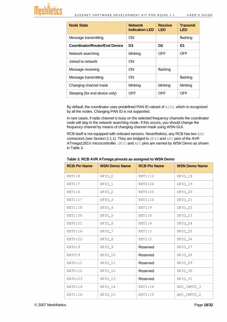
Table 3. RCB AVR ATmega pinouts as assigned to WSN Demo
RCB Pin Name WSN Demo Name RCB Pin Name WSN Demo Name
EXT1:8 GPIO_0 EXT1:13 GPIO_18
EXT1:7 GPIO_1 EXT0:24 GPIO_19
EXT1:6 GPIO_2 EXT0:25 GPIO_20
EXT1:17 GPIO_3 EXT1:10 GPIO_21
EXT1:18 GPIO_4 EXT1:9 GPIO_22
EXT1:30 GPIO_5 EXT1:8 GPIO_23
EXT0:21 GPIO_6 EXT1:4 GPIO_24
EXT0:16 GPIO_7 EXT1:3 GPIO_25
EXT0:22 GPIO_8 EXT1:5 GPIO_26
EXT0:9 GPIO_9 Reserved GPIO_27
EXT0:9 GPIO_10 Reserved GPIO_28
EXT0:11 GPIO_11 Reserved GPIO_29
EXT0:12 GPIO_12 Reserved GPIO_30
EXT0:23 GPIO_13 Reserved GPIO_31
EXT0:14 GPIO_14 EXT1:16 ADC_INPUT_3
EXT1:16 GPIO_15 EXT1:15 ADC_INPUT_2
© 2007 MeshNetics Page 18/32

E Z E E N E T S O F T W A R E D E V E L O P M E N T K I T F O R R Z 2 0 0 1 . 1 U S E R ’ S G U I D E
RCB Pin Name WSN Demo Name RCB Pin Name WSN Demo Name
EXT1:15 GPIO_16 EXT1:14 ADC_INPUT_1
EXT1:14 GPIO_17 EXT1:13 ADC_INPUT_0
Note that EXT1:13 … EXT1:16 are doubly used for both ADC and GPIO.
EXT0 and EXT1 connectors can serve as sensor inputs for any RCB linked wirelessly as router or end device. EXT0 and EXT1 slots may be used to connect customized sensor unit and enable sensor readings.
NOTE:
GPIO_0, GPIO_1, GPIO_2, GPIO_23 are assigned to control RCB’s LEDs. GPIO_26 is attached to the RCB button.You may not use those pins for sensors.
Node and sensor status screen shown in Figure 10 displays current values for GPIO0 … GPIO31 logical inputs and ADC0 … ADC3 input voltage digitized as 10-bit values (ranged from 0 to 1023). ADC and GPIO inputs will show arbitrary data unless they are connected to sensors.
IMPORTANT NOTE:
The input voltage must not exceed 1,1V for ADC0..ADC3! GPIO inputs must be limited by VCC value. To avoid damaging RCB circuitry, any attached sensor must strictly obey the power requirement. Refer to RCB controller schematics for details.
4.4. WSN Monitor Lite WSN Monitor Lite provides WSN Demo application with the GUI to display WSN topology and other information about the WSN network.
When the application starts, the Meshnetics’ splash screen is first displayed on the LCD as shown in Figure 6.
Figure 6. The Display Board with splash screen
Network conditions can be monitored from either the network topology screen or the node characteristic screens.
© 2007 MeshNetics Page 19/32
E Z E E N E T S O F T W A R E D E V E L O P M E N T K I T F O R R Z 2 0 0 1 . 1 U S E R ’ S G U I D E
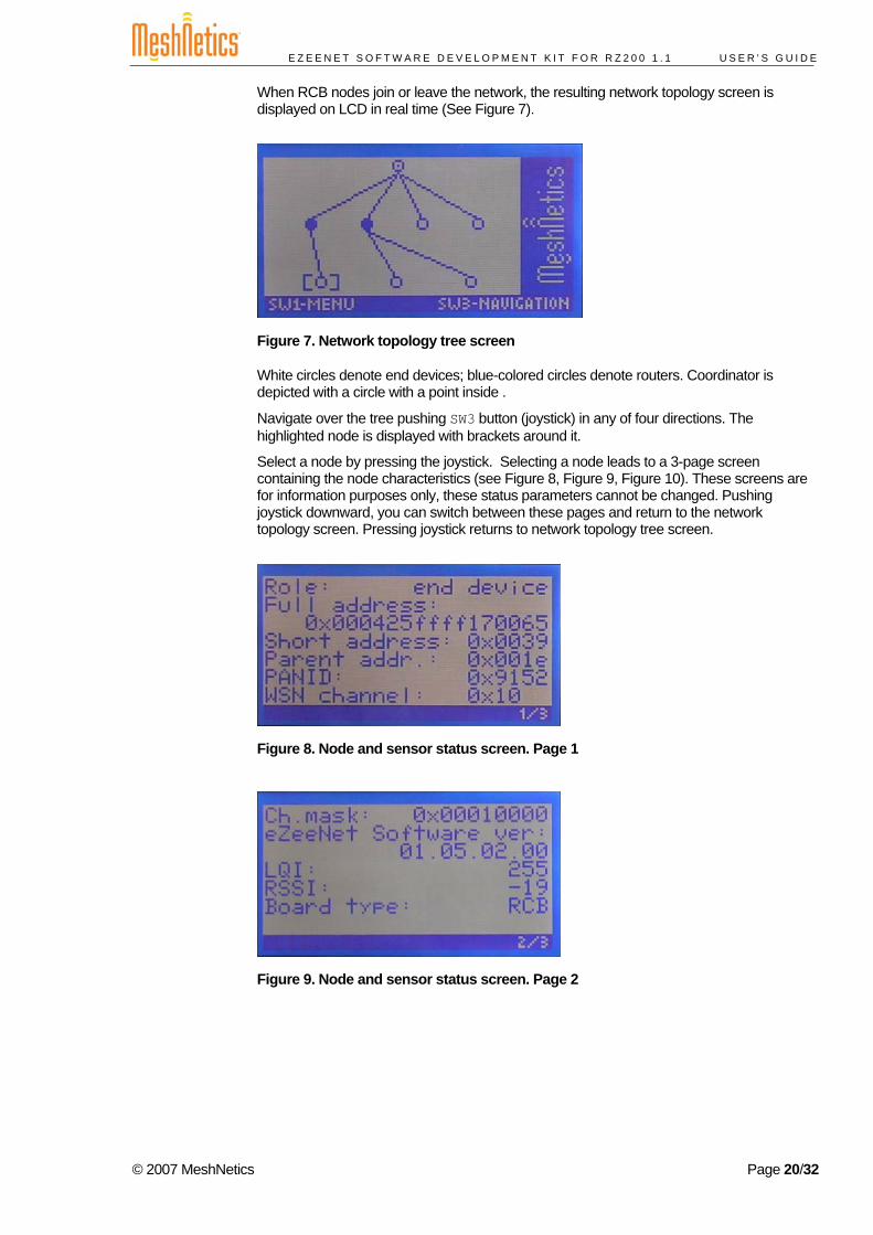
When RCB nodes join or leave the network, the resulting network topology screen is displayed on LCD in real time (See Figure 7).
Figure 7. Network topology tree screen
White circles denote end devices; blue-colored circles denote routers. Coordinator is depicted with a circle with a point inside .
Navigate over the tree pushing SW3 button (joystick) in any of four directions. The highlighted node is displayed with brackets around it.
Select a node by pressing the joystick. Selecting a node leads to a 3-page screen containing the node characteristics (see Figure 8, Figure 9, Figure 10). These screens are for information purposes only, these status parameters cannot be changed. Pushing joystick downward, you can switch between these pages and return to the network topology screen. Pressing joystick returns to network topology tree screen.
Figure 8. Node and sensor status screen. Page 1
Figure 9. Node and sensor status screen. Page 2
© 2007 MeshNetics Page 20/32
E Z E E N E T S O F T W A R E D E V E L O P M E N T K I T F O R R Z 2 0 0 1 . 1 U S E R ’ S G U I D E
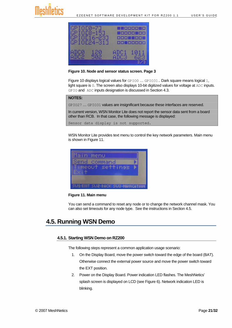
Figure 10. Node and sensor status screen. Page 3
Figure 10 displays logical values for GPIO0 … GPIO31. Dark square means logical 1, light square is 0. The screen also displays 10-bit digitized values for voltage at ADC inputs. GPIO and ADC inputs designation is discussed in Section 4.3.
NOTES:
GPIO27 … GPIO31 values are insignificant because these interfaces are reserved.
In current version, WSN Monitor Lite does not report the sensor data sent from a board other than RCB. In that case, the following message is displayed:
Sensor data display is not supported.
WSN Monitor Lite provides text menu to control the key network parameters. Main menu is shown in Figure 11.
Figure 11. Main menu
You can send a command to reset any node or to change the network channel mask. You can also set timeouts for any node type. See the instructions in Section 4.5.
4.5. Running WSN Demo
4.5.1. Starting WSN Demo on RZ200
The following steps represent a common application usage scenario:
1. On the Display Board, move the power switch toward the edge of the board (BAT).
Otherwise connect the external power source and move the power switch toward
the EXT position.
2. Power on the Display Board. Power indication LED flashes. The MeshNetics’
splash screen is displayed on LCD (see Figure 6). Network indication LED is
blinking.
© 2007 MeshNetics Page 21/32
E Z E E N E T S O F T W A R E D E V E L O P M E N T K I T F O R R Z 2 0 0 1 . 1 U S E R ’ S G U I D E
3. Power on the RCB attached to the Display Board by moving power switch away the
antenna. The coordinator starts scanning for other devices. Network indication LED
is ON. LCD starts displaying the WSN topology tree with only the coordinator.
NOTE:
If you turn on the power on the coordinator, it will switch to the active state, even though no child node is present. This is normal, it means that the coordinator is ready and child nodes can join the network with coordinator’s PAN ID.
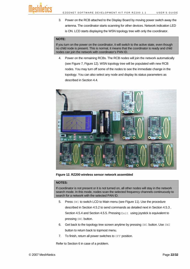
4. Power on the remaining RCBs. The RCB nodes will join the network automatically
(see Figure 7, Figure 12). WSN topology tree will be populated with new RCB
nodes. You may turn off some of the nodes to see the immediate change in the
topology. You can also select any node and display its status parameters as
described in Section 4.4.
Figure 12. RZ200 wireless sensor network assembled
NOTES:
If coordinator is not present or it is not turned on, all other nodes will stay in the network search mode. In this mode, nodes scan the selected frequency channels continuously to search for a network with the selected PAN ID.
5. Press SW1 to switch LCD to Main menu (see Figure 11). Use the procedure
described in Section 4.5.2 to send commands as detailed next in Section 4.5.3 ,
Section 4.5.4 and Section 4.5.5. Pressing Exit using joystick is equivalent to
pressing SW1 button.
6. Get back to the topology tree screen anytime by pressing SW1 button. Use SW2
button to return back to topmost menu.
7. To finish, return all power switches to OFF position.
Refer to Section 6 in case of a problem.
© 2007 MeshNetics Page 22/32
E Z E E N E T S O F T W A R E D E V E L O P M E N T K I T F O R R Z 2 0 0 1 . 1 U S E R ’ S G U I D E
4.5.2. Using the Menu
An active menu item is highlighted in white. To navigate through the menu items push SW3 button (joystick) in any of four directions.
Select a menu item by pressing the joystick. Selecting a menu item marked with the ‘>’ sign opens the corresponding sub-menu. Otherwise, the action assigned to the item is executed.
A terminal menu may include some parameters to be input by the user. The corresponding input fields or the field parts are outlined with angle brackets (see Figure 14 for example). To specify a desired parameter, navigate to the field using joystick and press the joystick. You will enter one of two editing modes. Depending on the field you can:
• enable a whole-field selection (choose mode) or • make the field editable (position-edit mode).
In choose mode, make your choice among the preset values for this field. Press joystick vertically, upward or downward to select one (see Figure 15 for example).
In position-edit mode, you will see a blinking cursor (see Figure 16 for example). To select a cursor position for input, press joystick horizontally, leftward or rightward. To input into the current position, press joystick upward or downward. To leave choose mode or position-edit mode, press joystick again.
NOTES:
While editing a field, you cannot proceed to another field or menu item.
After input into any position, cursor does not move itself automatically. You should move it manually.
All inputs are context sensitive. That means that only options and characters appropriate for this field can be selected. For instance, you are prevented from selecting a hexadecimal digit to enter instead of a decimal; you can never select an address of a node which is not present in a network and so on.
4.5.3. Resetting a Node
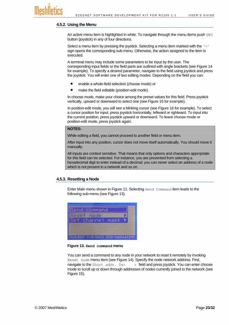
Enter Main menu shown in Figure 11. Selecting Send Command item leads to the following sub-menu (see Figure 13).
Figure 13. Send command menu
You can send a command to any node in your network to reset it remotely by invoking Reset node menu item (see Figure 14). Specify the node network address. First, navigate to the Short addr. 0x< > field and press joystick. You can enter choose mode to scroll up or down through addresses of nodes currently joined to the network (see Figure 15).
© 2007 MeshNetics Page 23/32
E Z E E N E T S O F T W A R E D E V E L O P M E N T K I T F O R R Z 2 0 0 1 . 1 U S E R ’ S G U I D E
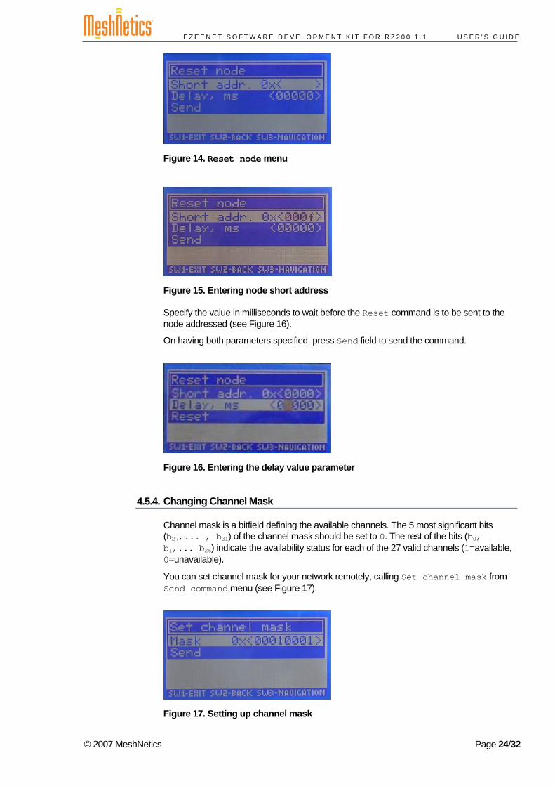
Figure 14. Reset node menu
Figure 15. Entering node short address
Specify the value in milliseconds to wait before the Reset command is to be sent to the node addressed (see Figure 16).
On having both parameters specified, press Send field to send the command.
Figure 16. Entering the delay value parameter
4.5.4. Changing Channel Mask
Channel mask is a bitfield defining the available channels. The 5 most significant bits (b27,... , b31) of the channel mask should be set to 0. The rest of the bits (b0, b1,... b26) indicate the availability status for each of the 27 valid channels (1=available, 0=unavailable).
You can set channel mask for your network remotely, calling Set channel mask from Send command menu (see Figure 17).
Figure 17. Setting up channel mask
© 2007 MeshNetics Page 24/32
E Z E E N E T S O F T W A R E D E V E L O P M E N T K I T F O R R Z 2 0 0 1 . 1 U S E R ’ S G U I D E
Specify the channel mask for your network in Mask field. Press Send field to send the command.
When changing channel mask, coordinator sends the command to all the nodes and waits for 1 minute to receive the last packet sent using the old channel mask. Next, the coordinator forms the network on the new channel.
When channel mask command is being accepted by router or end device the node stops sending packets for 1 minute and starts blinking all its LEDs. It then leaves the network and proceeds to rejoining using new channel mask.
When router is rejoining, the network indication LED (D3) is blinking. Upon joining, LED is remains ON.
When end device is rejoining, the network indication LED (D3) is blinking. Upon joining, LED flashes shortly to indicate sending of a packet. Next, the LED turns OFF when end device is returns to sleep.
When channel mask is being changed, the topology screen may not display real topology tree. After changing channel mask the network topology tree is redrawn.
NOTE:
Channel mask is stored persistently. The recently set channel mask is available in coordinator’s EEPROM upon the board being powered ON.
4.5.5. Setting Up Node Timeouts
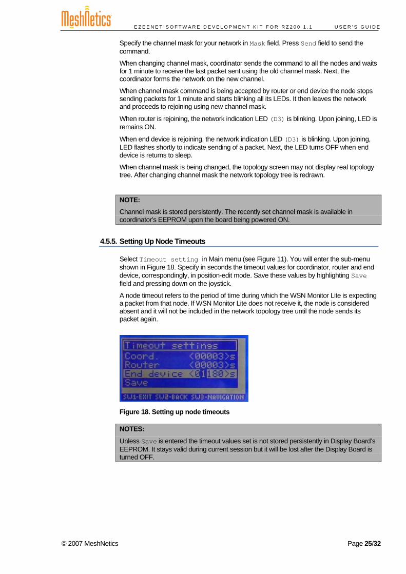
Select Timeout setting in Main menu (see Figure 11). You will enter the sub-menu shown in Figure 18. Specify in seconds the timeout values for coordinator, router and end device, correspondingly, in position-edit mode. Save these values by highlighting Save field and pressing down on the joystick.
A node timeout refers to the period of time during which the WSN Monitor Lite is expecting a packet from that node. If WSN Monitor Lite does not receive it, the node is considered absent and it will not be included in the network topology tree until the node sends its packet again.
Figure 18. Setting up node timeouts
NOTES:
Unless Save is entered the timeout values set is not stored persistently in Display Board’s EEPROM. It stays valid during current session but it will be lost after the Display Board is turned OFF.
© 2007 MeshNetics Page 25/32
E Z E E N E T S O F T W A R E D E V E L O P M E N T K I T F O R R Z 2 0 0 1 . 1 U S E R ’ S G U I D E
5. Using eZeeNet API eZeeNet Software allows a user to develop custom applications. Full functionality of eZeeNet Software becomes available when employing eZeeNet API. This includes configuration of:
• WSN network common parameters (PAN ID, channel mask) • Node role (being coordinator, router or end device) • Node MAC address • RF output power.
User’s application is enabled to control a WSN with respect to: • Network formation (through coordinator node) • Node join/leaving • Data transmission over the WSN network • Data transportation through UART interface for further data acquisition • Node power management • Accessing node peripherals etc.
The extensive description of eZeeNet API can be found in [3]. That document contains detailed instructions on how to build custom applications. It includes a sample application in source code.
5.1. Sample Application Development Two applications in source code are delivered with the Kit:
• WSN Demo • WSN Monitor Lite.
Operation details are presented in Section 4. The present section introduces a user to the development of custom applications based on the delivered code. The instructions on how to compile it and how to run software are given in Section 5.1.1 and Section 5.1.2. To start, the following tools are necessary.
We recommend using Atmel’s AVR Studio [6]. This Integrated Development Environment (IDE) provides editing a source code, compiling, linking object modules with libraries, debugging, making executable file automatically, and more. AVR Studio can be integrated with WinAVR, a suite of software development tools for the Atmel AVR series of RISC microprocessors hosted on the Windows platform [8]. WinAVR contains a set of utilities including AVR GCC compiler, linker, automatic Makefile generator, system libraries etc. Installation of the AVR GCC plug-in lets those tools working automatically in AVR Studio. GCC compiler is designed to be executed on the Windows platform, and is configured to compile C or C++ codes.
Current version of the AVR Studio with Service Pack may be downloaded freely from Atmel’s website (http://www.atmel.com). Simply launch the downloaded installation programs and follow the setup instructions. The WinAVR suite containing the development tools can be downloaded from http://sourceforge.net/projects/winavr. To install WinAVR follow the setup instructions.
5.1.1. Building the WSN Demo
WSN Demo application is developed on top of the standard eZeeNet Software.
The source code for WSN Demo application can be found in ./API/SampleApplication/WSNDemo subdirectory (see Appendix A).
© 2007 MeshNetics Page 26/32
E Z E E N E T S O F T W A R E D E V E L O P M E N T K I T F O R R Z 2 0 0 1 . 1 U S E R ’ S G U I D E
eZeeNet Software (including Framework, Stack and Stack Support) is delivered as the header and the library files. They can be found, correspondingly, in:
./API/Framework
./API/Stack
./API/StackSupport.
eZeeNet HAL is delivered along with source code. It can be found in
./API/HAL/HAL_R6.
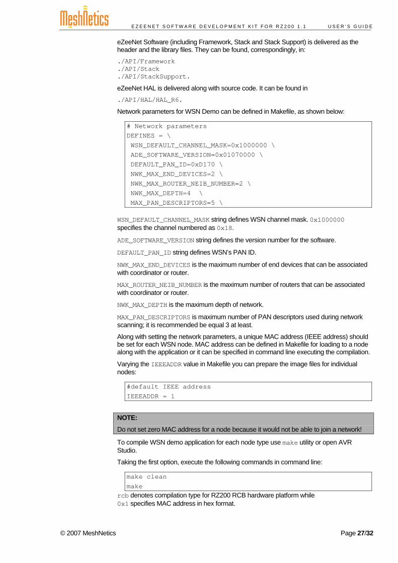
Network parameters for WSN Demo can be defined in Makefile, as shown below:
# Network parameters DEFINES = \ WSN_DEFAULT_CHANNEL_MASK=0x1000000 \ ADE_SOFTWARE_VERSION=0x01070000 \ DEFAULT_PAN_ID=0xD170 \ NWK_MAX_END_DEVICES=2 \ NWK_MAX_ROUTER_NEIB_NUMBER=2 \ NWK_MAX_DEPTH=4 \ MAX_PAN_DESCRIPTORS=5 \
WSN_DEFAULT_CHANNEL_MASK string defines WSN channel mask. 0x1000000 specifies the channel numbered as 0x18.
ADE_SOFTWARE_VERSION string defines the version number for the software.
DEFAULT_PAN_ID string defines WSN’s PAN ID.
NWK_MAX_END_DEVICES is the maximum number of end devices that can be associated with coordinator or router.
MAX_ROUTER_NEIB_NUMBER is the maximum number of routers that can be associated with coordinator or router.
NWK_MAX_DEPTH is the maximum depth of network.
MAX_PAN_DESCRIPTORS is maximum number of PAN descriptors used during network scanning; it is recommended be equal 3 at least.
Along with setting the network parameters, a unique MAC address (IEEE address) should be set for each WSN node. MAC address can be defined in Makefile for loading to a node along with the application or it can be specified in command line executing the compilation.
Varying the IEEEADDR value in Makefile you can prepare the image files for individual nodes:
#default IEEE address IEEEADDR = 1
NOTE:
Do not set zero MAC address for a node because it would not be able to join a network!
To compile WSN demo application for each node type use make utility or open AVR Studio.
Taking the first option, execute the following commands in command line:
make clean make
rcb denotes compilation type for RZ200 RCB hardware platform while 0x1 specifies MAC address in hex format.
© 2007 MeshNetics Page 27/32
E Z E E N E T S O F T W A R E D E V E L O P M E N T K I T F O R R Z 2 0 0 1 . 1 U S E R ’ S G U I D E
Otherwise, just open the WSNDemo.aps file with AVR Studio. This file can be found in .API/SampleApplication/WSNDemo subdirectory. Execute Build/Rebuild All item from the main menu.
As a result the image files will be generated in *.elf, in *.hex and in *.srec formats each having one of the following filenames:
• wsndemo_rcb_c_1 for coordinator
• wsndemo_rcb_e_x for end device
• wsndemo_rcb_r_x for router.
To drive the WSN nodes WSN Demo operates as follows:
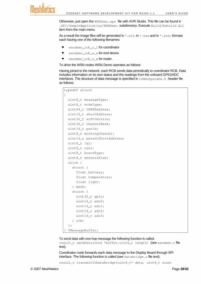
Having joined to the network, each RCB sends data periodically to coordinator RCB. Data includes information on its own status and the readings from the onboard GPIO/ADC interfaces. The structure of data message is specified in commonparams.h header file as follows:
typedef struct { uint8_t messageType; uint8_t nodeType; uint64_t IEEEAddress; uint16_t shortAddress; uint32_t softVersion; uint32_t channelMask; uint16_t panId; uint8_t workingChannel; uint16_t parentShortAddress; uint8_t lqi; uint8_t rssi; uint8_t boardType; uint8_t sensorsSize; union { struct { float battery; float temperature; float light; } mesh; struct { uint32_t gpio; uint16_t adc0; uint16_t adc1; uint16_t adc2; uint16_t adc3; } rcb; }; } TMessageBuffer;
To send data with one-hop message the following function is called: result_t sendData(void *buffer,uint8_t length) (see wsndemo.c file text).
Coordinator node forwards each data message to the Display Board through SPI interface. The following function is called (see databridge.c file text):
result_t transmitToDataBridge(uint8_t* data, uint8_t size)
© 2007 MeshNetics Page 28/32
E Z E E N E T S O F T W A R E D E V E L O P M E N T K I T F O R R Z 2 0 0 1 . 1 U S E R ’ S G U I D E
5.1.2. Building the WSN Monitor Lite
WSN Monitor Light application is designed for the Display Board to provide GUI for WSN Demo application which runs on RCBs. The onboard SPI interface is used to exchange data between WSN Monitor Light and WSN Demo applications.
The source code for WSN Monitor Lite can be found in ./API/SampleApplication/wsnml subdirectory (see Appendix A).
To compile WSN demo application you can use make utility. Execute the following commands in command line:
make clean make
Otherwise, open the wsnml.aps file from the .API/SampleApplication/wsnml subdirectory with AVR Studio and just execute Build/Rebuild All item from the main menu.
WSN Monitor Light itself does not provide WSN functionality. This GUI application is used just to visualize data and to transfer user’s commands to WSN coordinator node via SPI interface.
WSN Monitor Light implements a simple executive model without using RTOS features like those inherent to the eZeeNet Software.
The main loop function is encoded as wsnmlMainLoop(void) within wsnml.c section.
The message parsing function is implemented as DataMessage_t *parseMessage(uint8_t *m) within parser.c file.
The showTopology() function is implemented within top.c section to draw WSN topology on LCD screen.
© 2007 MeshNetics Page 29/32
E Z E E N E T S O F T W A R E D E V E L O P M E N T K I T F O R R Z 2 0 0 1 . 1 U S E R ’ S G U I D E
6. Troubleshooting In case of any operational problem, please check the power first. Make sure that all of your equipment is properly connected. Check on LED indication of a node, if it is not responding or behaving unusually.
If a board does not indicate its activity with LEDs, make sure that WSN Demo images are loaded.
You may be required to reset the node.
Extensive information on troubleshooting when working with the boards is contained in [1].
If you have a problem with developing WSN applications refer to eZeeNet API desciprtion in [3].
© 2007 MeshNetics Page 30/32
E Z E E N E T S O F T W A R E D E V E L O P M E N T K I T F O R R Z 2 0 0 1 . 1 U S E R ’ S G U I D E
Appendices
Appendix A. Delivery File Set
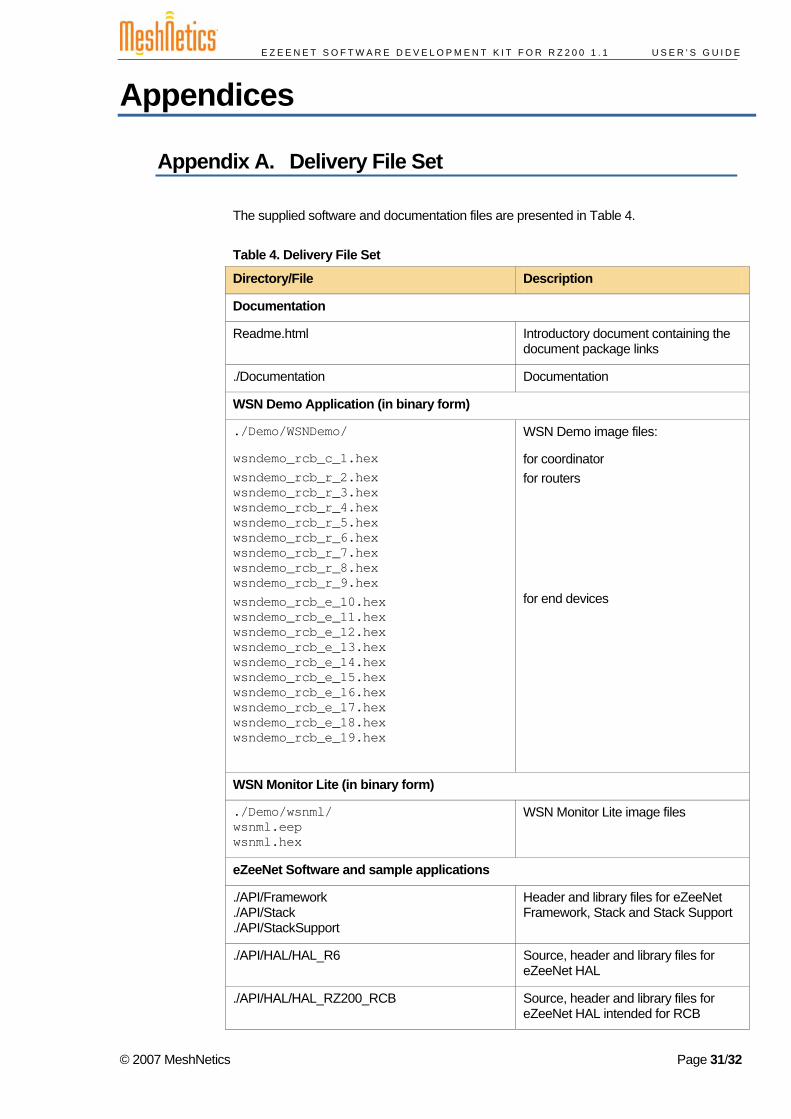
The supplied software and documentation files are presented in Table 4.
Table 4. Delivery File Set
Directory/File Description
Documentation
Readme.html Introductory document containing the document package links
./Documentation Documentation
WSN Demo Application (in binary form)
./Demo/WSNDemo/
wsndemo_rcb_c_1.hex wsndemo_rcb_r_2.hex wsndemo_rcb_r_3.hex wsndemo_rcb_r_4.hex wsndemo_rcb_r_5.hex wsndemo_rcb_r_6.hex wsndemo_rcb_r_7.hex wsndemo_rcb_r_8.hex wsndemo_rcb_r_9.hex wsndemo_rcb_e_10.hex wsndemo_rcb_e_11.hex wsndemo_rcb_e_12.hex wsndemo_rcb_e_13.hex wsndemo_rcb_e_14.hex wsndemo_rcb_e_15.hex wsndemo_rcb_e_16.hex wsndemo_rcb_e_17.hex wsndemo_rcb_e_18.hex wsndemo_rcb_e_19.hex
WSN Demo image files:
for coordinator for routers
for end devices
WSN Monitor Lite (in binary form)
./Demo/wsnml/ wsnml.eep wsnml.hex
WSN Monitor Lite image files
eZeeNet Software and sample applications
./API/Framework
./API/Stack
./API/StackSupport
Header and library files for eZeeNet Framework, Stack and Stack Support
./API/HAL/HAL_R6 Source, header and library files for eZeeNet HAL
./API/HAL/HAL_RZ200_RCB Source, header and library files for eZeeNet HAL intended for RCB
© 2007 MeshNetics Page 31/32
E Z E E N E T S O F T W A R E D E V E L O P M E N T K I T F O R R Z 2 0 0 1 . 1 U S E R ’ S G U I D E
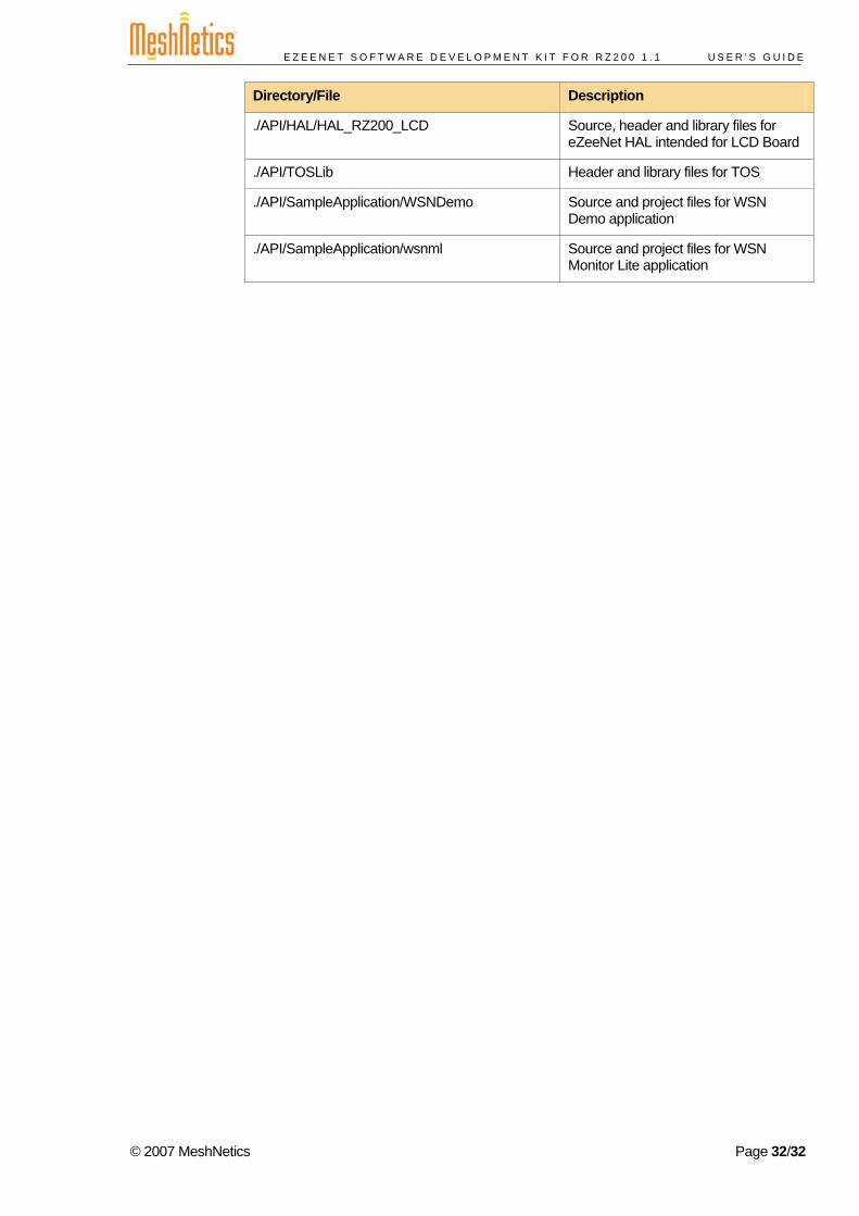
Directory/File Description
./API/HAL/HAL_RZ200_LCD Source, header and library files for eZeeNet HAL intended for LCD Board
./API/TOSLib Header and library files for TOS
./API/SampleApplication/WSNDemo Source and project files for WSN Demo application
./API/SampleApplication/wsnml Source and project files for WSN Monitor Lite application
© 2007 MeshNetics Page 32/32


2](https://img.pdfslide.net/doc/110x75/5f71d23276e8ef4c756ac9f7/association-of-the-dawson-type-polyoxometalates-with-dorasdcuie166171phdthesisjamesjwalshrpdf.jpg)

![eZeeNet™ Software 1 - Imperial College London · Connection with board ... software [9], which contains 802.15.4 MAC and ZigBee NWK layers enabling wireless ... LED Light Emitting](https://img.pdfslide.net/doc/110x75/5b793cba7f8b9ad77e8d18c3/ezeenet-software-1-imperial-college-connection-with-board-software.jpg)