Embed Size (px)
Citation preview
F-104 Wing Structure Design Using FEA William VonHagen (AE, Class of 2009)
Dan Galbraith (AE, Class of 2009)
Lockheed F-104 Starfighter in flight (Only tip tanks are attached)
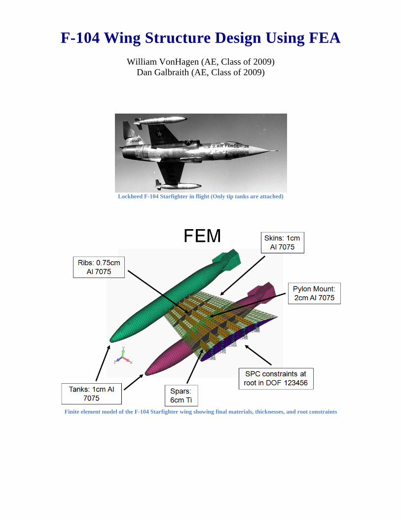
Finite element model of the F-104 Starfighter wing showing final materials, thicknesses, and root constraints
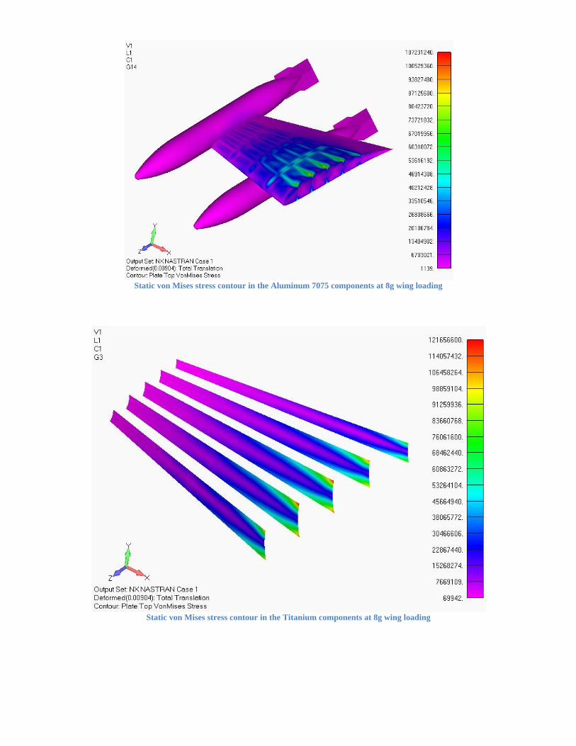
Static von Mises stress contour in the Aluminum 7075 components at 8g wing loading
Static von Mises stress contour in the Titanium components at 8g wing loading
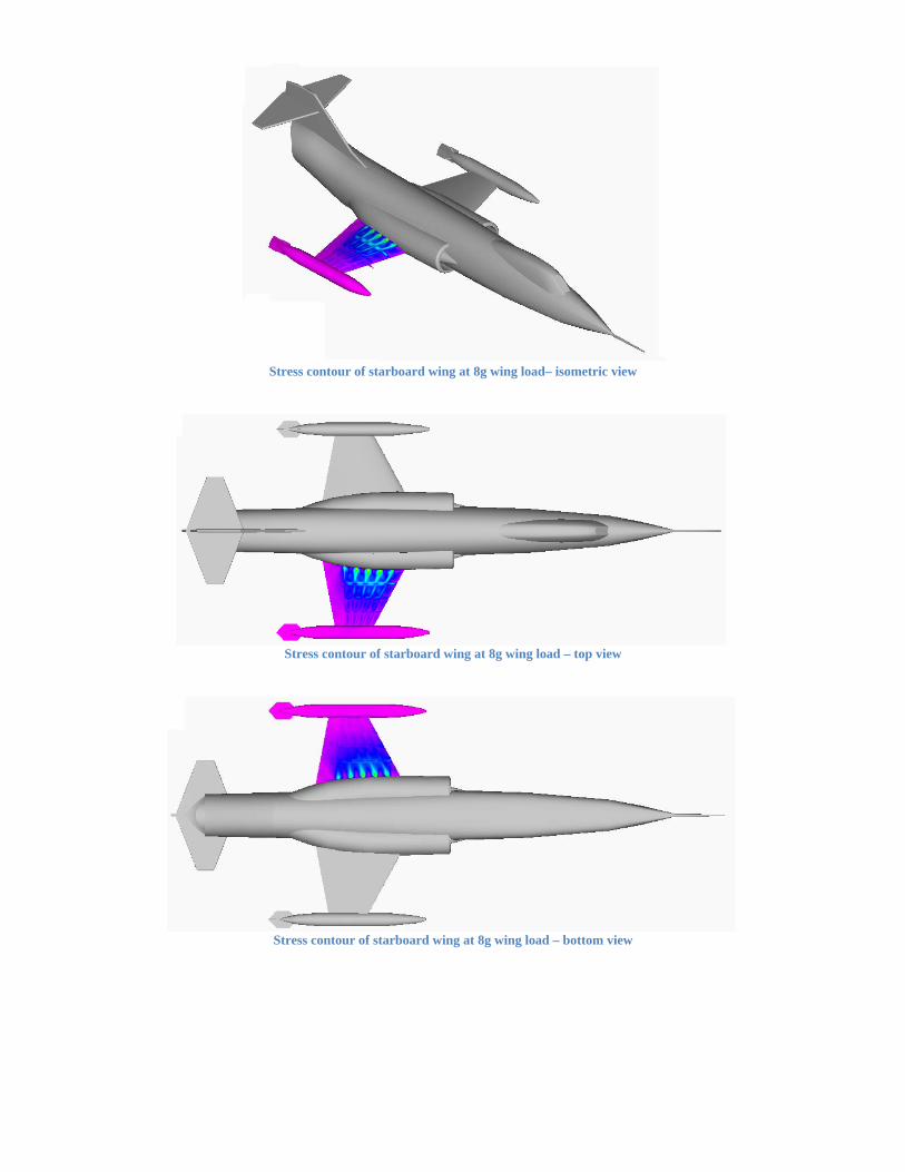
Stress contour of starboard wing at 8g wing load– isometric view
Stress contour of starboard wing at 8g wing load – top view
Stress contour of starboard wing at 8g wing load – bottom view
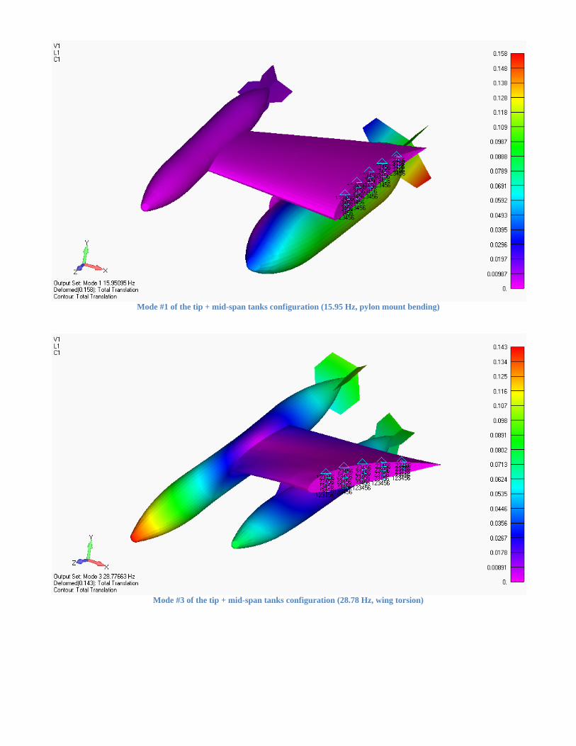
Mode #1 of the tip + mid-span tanks configuration (15.95 Hz, pylon mount bending)
Mode #3 of the tip + mid-span tanks configuration (28.78 Hz, wing torsion)
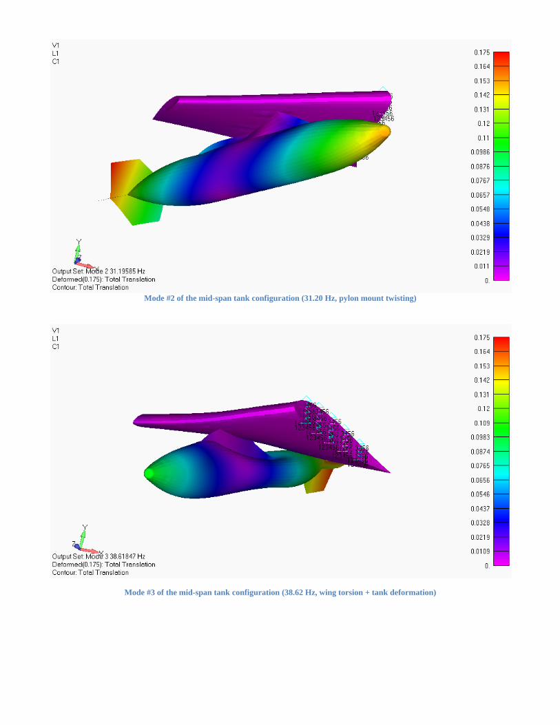
Mode #2 of the mid-span tank configuration (31.20 Hz, pylon mount twisting)
Mode #3 of the mid-span tank configuration (38.62 Hz, wing torsion + tank deformation)
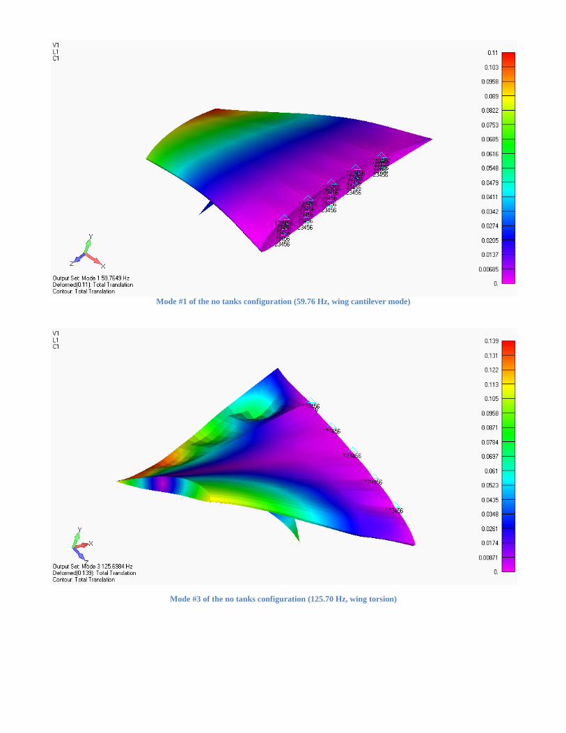
Mode #1 of the no tanks configuration (59.76 Hz, wing cantilever mode)
Mode #3 of the no tanks configuration (125.70 Hz, wing torsion)

![98 - StallionESearch.com · Poker Face B SI 104 (c. by Teller Cart el). 4 wins to 3, $45,996, 3rdHarrah’s En tert ain ment Fu tu rity[G3]. Tiny First Fea ture SI 98 (c. by Fea ture](https://img.pdfslide.net/doc/110x75/5f5225811b717307913749b4/98-poker-face-b-si-104-c-by-teller-cart-el-4-wins-to-3-45996-3rdharrahas.jpg)