Embed Size (px)
DESCRIPTION
Part two of the pilot's handbook for F-16 Block 52's (those F-16's that have undergone the Mid-Life Upgrade and received an updated avionics suite).
Citation preview

16PR1526915 March 2000
F-16 A/B MID-LIFE UPDATEPRODUCTION TAPE M2
THEPILOT’S GUIDE
to new capabilities & cockpit enhancements
F33657-94-C-2259ECP 2242/2242-1
CDRL D034
Releasability of this material under the Freedom of Information Act is subject to the restrictions on release in DoD regulation 5400.7-R and DoD Directive 5230.25
Copyright 2000 by Lockheed Martin CorporationAll rights reserved.
This material may be reproduced by the U.S. Government pursuant to the copyright license under the clause at DFARS 252.227-7013 (October 1988).


LOCKHEED MARTIN 16PR15269Aeronautics Company 15 March 2000
CODE IDENT: 81755
F-16 A/B MID-LIFE UPDATEPRODUCTION TAPE M2
THEPILOT’S GUIDE
to new capabilities & cockpit enhancementsF33657-94-C-2259ECP 2242/2242-1
CDRL D034
Prepared by: Reviewed by:
F. A. Gorg S. E. DarlandPilot-Vehicle Interface Pilot-Vehicle Interface M2/M2+ Lead
Reviewed by: Approved by:
Gary L. Kolling Ronald R. BessireAvionics System Requirements M2/M2+ Program Manager
Releasability of this material under the Freedom of Information Act is subject to the Restrictions on release in DoD Regulation 5400.7-R and DoD and DoD Directive 5230.25
Copyright 2000 by Lockheed Martin Corporation.All rights reserved.
This material may be reproduced by or for the U.S. Government pursuant to the copyright license under the clause at DFARS 252.227-7013 (October 1988)


16PR15269
Table of Contents
Description Page
INTRODUCTION . . . . . . . . . . . . . . . . . . . . . . . . . . . . . . . . . . . . . . . . . . . . . . . . . . . . . . 1
SECTION 1 - GENERAL . . . . . . . . . . . . . . . . . . . . . . . . . . . . . . . . . . . . . . . . . . . . . . . . 3Core Avionics Provisions (RDP-052) . . . . . . . . . . . . . . . . . . . . . . . . . . . . . . . . . . . . . . . . . . . 3Avionics Selection After MMC Power Cycle (RDP-1367) . . . . . . . . . . . . . . . . . . . . . . . . . . . 3Jettison Delay For 600 Gallon Tanks (RDP-2000) . . . . . . . . . . . . . . . . . . . . . . . . . . . . . . . . . 3AN/ARC-186R VHF Radio 8.33 kHz Channel Spacing (RDP-1701) . . . . . . . . . . . . . . . . . . 3Autonomous ACMI (RDP-867) . . . . . . . . . . . . . . . . . . . . . . . . . . . . . . . . . . . . . . . . . . . . . . . . 4Color Display Optimization (RDP-1054) . . . . . . . . . . . . . . . . . . . . . . . . . . . . . . . . . . . . . . . . 5Color Data Linked Information Outside The HSD FOV (RDP-884) . . . . . . . . . . . . . . . . . . . 7MFD Horizon Line Incorrect When Inverted (RDP-1246) . . . . . . . . . . . . . . . . . . . . . . . . . . . 8MFD Contrast/Brightness Control (RDP-1160) . . . . . . . . . . . . . . . . . . . . . . . . . . . . . . . . . . . 9MFD Display Gain Control Option Incorporation (RDP-1703) . . . . . . . . . . . . . . . . . . . . . . 11Reduced Size Of FCR Symbology (RDP-925) . . . . . . . . . . . . . . . . . . . . . . . . . . . . . . . . . . . 11GPS Time Available On Bus/GPS Time Use (RDP-1159) . . . . . . . . . . . . . . . . . . . . . . . . . . 12
SECTION 2 - NAVIGATION . . . . . . . . . . . . . . . . . . . . . . . . . . . . . . . . . . . . . . . . . . . . . 13Digital Terrain System (DTS) Phase II (RDP-1077) . . . . . . . . . . . . . . . . . . . . . . . . . . . . . . . 13DBTC Whiskers (RDP-1510) . . . . . . . . . . . . . . . . . . . . . . . . . . . . . . . . . . . . . . . . . . . . . . . . 21Roll Stabilized DTS DBTC Cue (RDP-1244) . . . . . . . . . . . . . . . . . . . . . . . . . . . . . . . . . . . . 21HSD Freeze Enhancements (RDP-1053) . . . . . . . . . . . . . . . . . . . . . . . . . . . . . . . . . . . . . . . . 21HSD Declutter By Master Mode (RDP-972) . . . . . . . . . . . . . . . . . . . . . . . . . . . . . . . . . . . . . 23Identify The Active Navigation Route (RDP-1002) . . . . . . . . . . . . . . . . . . . . . . . . . . . . . . . 24NVP Boresight And Faults (RDP-1169) . . . . . . . . . . . . . . . . . . . . . . . . . . . . . . . . . . . . . . . . 24NVP Laser Spot Locator (RDP-1171) . . . . . . . . . . . . . . . . . . . . . . . . . . . . . . . . . . . . . . . . . . 25Include Current Master Mode In DTE Load (RDP-314) . . . . . . . . . . . . . . . . . . . . . . . . . . . . 25Hands-On Declutter Of HUD Symbology (Landing Phase) (RDP-869) . . . . . . . . . . . . . . . . 26Time-Over-Steerpoint (TOS) Refinements (RDP-259) . . . . . . . . . . . . . . . . . . . . . . . . . . . . . 26UTM Coordinate Entry Up To Four Digits (RDP-597) . . . . . . . . . . . . . . . . . . . . . . . . . . . . 28
SECTION 3 - AIR-TO-AIR . . . . . . . . . . . . . . . . . . . . . . . . . . . . . . . . . . . . . . . . . . . . . . 29AIFF Mode Interrogation Enhancement (RDP-878) . . . . . . . . . . . . . . . . . . . . . . . . . . . . . . . 30Auto Time Mode Enhancement (RDP-879) . . . . . . . . . . . . . . . . . . . . . . . . . . . . . . . . . . . . . 30AIFF Interrogator Coupling To IFF Transponder Modes (RDP-1235); AIFF Changes And
AIFF Target Display Conflict (RDP-1702) . . . . . . . . . . . . . . . . . . . . . . . . . . . . . . . . . . . 30SCAN/LOS Mechanization (RDP-1236) . . . . . . . . . . . . . . . . . . . . . . . . . . . . . . . . . . . . . . . . 34IFF Mode Number Inside AIFF Response Symbology (RDP-1237) . . . . . . . . . . . . . . . . . . 34Improved IDM Mechanization (RDP-1366) . . . . . . . . . . . . . . . . . . . . . . . . . . . . . . . . . . . . . 35IDM Automatic Target Hand-Off System (ATHS) (RDP-868) . . . . . . . . . . . . . . . . . . . . . . 35IDM-Allow A/A Target Assignments In Continuous Mode (RDP-875) . . . . . . . . . . . . . . . 40Highlight CONT Mnemonic To Indicate Active CONT Operation (RDP-1239) . . . . . . . . . 40
i

16PR15269
. . 44 . . 45 . . 45. . . 47 . . 49 . . 49. . . 49. . . 50 . . . 50 . . . 51 . . 51 . . . 52. . 52 . 53. . 5454. . 60. . 62 . . 63 . 64. . 64. . . 65
. . 67. . . 76. . 76. . . 77. . . 78. . . 79 . . 80
TABLE OF CONTENTS (Con’t)
IDM-Expand Net Size To 8 Members (RDP-872) . . . . . . . . . . . . . . . . . . . . . . . . . . . . . . . . 40IDM SEAD Changes (RDP-1015) . . . . . . . . . . . . . . . . . . . . . . . . . . . . . . . . . . . . . . . . . . . . . 41ASSIGN Message In HUD (RDP-1242) . . . . . . . . . . . . . . . . . . . . . . . . . . . . . . . . . . . . . . . . 42Ownship Symbol Occlusion By Team Member Data Link Symbols On HSD (RDP-1241) 42IDM Messages Zeroize (RDP-983) . . . . . . . . . . . . . . . . . . . . . . . . . . . . . . . . . . . . . . . . . . . . 42Flexible Data Link Steerpoints (71-80) (RDP-873) . . . . . . . . . . . . . . . . . . . . . . . . . . . . . . . 42ACM-One Switch Action To NO-RAD (RDP-626) . . . . . . . . . . . . . . . . . . . . . . . . . . . . . . . 43Bug Stepping To Track Files Limited To Selected Range (RDP-1158) . . . . . . . . . . . . . . . . 43SAM Multi-Track (SMT) Mode Transfer Remechanization (RDP-1165) . . . . . . . . . . . . . . 43Breaklock Reacquisition Symbology In SAM (RDP-1243) . . . . . . . . . . . . . . . . . . . . . . . . . 44Cursor Digital Search Altitude Information (RDP-351) . . . . . . . . . . . . . . . . . . . . . . . . . . . . 44HUD Ownship Bull’s-Eye (RDP-1229) . . . . . . . . . . . . . . . . . . . . . . . . . . . . . . . . . . . . . .Update Bull’s-Eye Position In Expand (RDP-1415) . . . . . . . . . . . . . . . . . . . . . . . . . . . . .LANTIRN Targeting Pod Interface (RDP-864) . . . . . . . . . . . . . . . . . . . . . . . . . . . . . . . .Attitude Awareness In DGFT (RDP-820) . . . . . . . . . . . . . . . . . . . . . . . . . . . . . . . . . . . . Target Altitude In HUD (RDP-1361) . . . . . . . . . . . . . . . . . . . . . . . . . . . . . . . . . . . . . . . .Heads Up Indication Of Imminent Radar Break Track (RDP-1049) . . . . . . . . . . . . . . . .EEGS Improvements: Flexible MRGS (RDP-796) . . . . . . . . . . . . . . . . . . . . . . . . . . . . . EEGS Improvements: Clamp MPLs (RDP-798) . . . . . . . . . . . . . . . . . . . . . . . . . . . . . . . Remove Max Range Dot When In Range (RDP-800) . . . . . . . . . . . . . . . . . . . . . . . . . . .Continuous FEDS (RDP-910) . . . . . . . . . . . . . . . . . . . . . . . . . . . . . . . . . . . . . . . . . . . . .No-Lock Training Mode (RDP-591) . . . . . . . . . . . . . . . . . . . . . . . . . . . . . . . . . . . . . . . . .Remech Hands-On Missile Select (RDP-1070) . . . . . . . . . . . . . . . . . . . . . . . . . . . . . . . .AIM-9L/M Bore/Slave Operations (RDP-519) . . . . . . . . . . . . . . . . . . . . . . . . . . . . . . . . . AIM-9 Auto Acquisition Mechanization (RDP-447) . . . . . . . . . . . . . . . . . . . . . . . . . . . . .Weapon Selection Not Affected By Inventory Manipulations (RDP-1503) . . . . . . . . . . . AMRAAM DLZ Changes (RDP-975); AMRAAM LOFT Cue (RDP-756) . . . . . . . . . . . . . AMRAAM Impact Remechanization (RDP-1238) . . . . . . . . . . . . . . . . . . . . . . . . . . . . . . New AMRAAM Versions (RDP-645) . . . . . . . . . . . . . . . . . . . . . . . . . . . . . . . . . . . . . . . AIM-120 Active Range Indications (993) . . . . . . . . . . . . . . . . . . . . . . . . . . . . . . . . . . . . .AIM-120 Launch Against Marginal Track Indications (RDP-986) . . . . . . . . . . . . . . . . . .AMRAAM Burn (RDP-964) . . . . . . . . . . . . . . . . . . . . . . . . . . . . . . . . . . . . . . . . . . . . . . . LOSE Cue In HUD Remechanization (RDP-1162) . . . . . . . . . . . . . . . . . . . . . . . . . . . .
SECTION 4 - AIR-TO-GROUND . . . . . . . . . . . . . . . . . . . . . . . . . . . . . . . . . . . . . . . . . 67LANTIRN Targeting Pod FLIR Interface (RDP-864) . . . . . . . . . . . . . . . . . . . . . . . . . . . Targeting Pod TV (RDP-1170) . . . . . . . . . . . . . . . . . . . . . . . . . . . . . . . . . . . . . . . . . . . . Attitude Advisory Function (AAF) (RDP-1502) . . . . . . . . . . . . . . . . . . . . . . . . . . . . . . . . Generic RECCE Pod II (RDP-865) . . . . . . . . . . . . . . . . . . . . . . . . . . . . . . . . . . . . . . . . . BAF RECCE Updates (RDP-1700) . . . . . . . . . . . . . . . . . . . . . . . . . . . . . . . . . . . . . . . . . New Strafe Pipper/Reticle (RDP-592) . . . . . . . . . . . . . . . . . . . . . . . . . . . . . . . . . . . . . . . Maverick Missile Launch Envelope (RDP-306) . . . . . . . . . . . . . . . . . . . . . . . . . . . . . . . .
ii

16PR15269
TABLE OF CONTENTS (Con’t)
Maverick Video Initiation (RDP-1240) . . . . . . . . . . . . . . . . . . . . . . . . . . . . . . . . . . . . . . . . . 81EO-VIS Auto SOI Sequencing (RDP-1164) . . . . . . . . . . . . . . . . . . . . . . . . . . . . . . . . . . . . . 81HARM (RDP-1200) . . . . . . . . . . . . . . . . . . . . . . . . . . . . . . . . . . . . . . . . . . . . . . . . . . . . . . . . 81Mark-84 Transonic Algorithm (RDP-612) . . . . . . . . . . . . . . . . . . . . . . . . . . . . . . . . . . . . . . 98Update CBU-87 Algorithm (RDP-625) . . . . . . . . . . . . . . . . . . . . . . . . . . . . . . . . . . . . . . . . . 99
SECTION 5 - DEFENSIVE AVIONICS . . . . . . . . . . . . . . . . . . . . . . . . . . . . . . . . . . . . 101Selectable Threat Range Rings On The HSD (RDP-967) . . . . . . . . . . . . . . . . . . . . . . . . . . 101Report Jamming Of AIFF Frequencies (RDP-880) . . . . . . . . . . . . . . . . . . . . . . . . . . . . . . . 101
INDEX . . . . . . . . . . . . . . . . . . . . . . . . . . . . . . . . . . . . . . . . . . . . . . . . . . . . . . . . . . . . . 103
ABBREVIATIONS & ACRONYMS . . . . . . . . . . . . . . . . . . . . . . . . . . . . . . . . . . . . . . . 109
iii

16PR15269
List of Figures
Figure Description Page
SECTION 1 - GENERAL1-1 DED AACMI Mode Selection . . . . . . . . . . . . . . . . . . . . . . . . . . . . . . . . . . . . . . . . . . . . . 51-2 Data Linked Targets Outside HSD FOV . . . . . . . . . . . . . . . . . . . . . . . . . . . . . . . . . . . . . 71-3 MFD Horizon Line Movement during Inverted Flight . . . . . . . . . . . . . . . . . . . . . . . . . . . 81-4 MFD Symbol Intensity, Brightness, And Contrast Controls . . . . . . . . . . . . . . . . . . . . . 101-5 MFD Reset Menu Page . . . . . . . . . . . . . . . . . . . . . . . . . . . . . . . . . . . . . . . . . . . . . . . . . 111-6 Comparison Of Reduced Symbol Size (Previous vs. Current Size) . . . . . . . . . . . . . . . . 111-7 DED TIME Page . . . . . . . . . . . . . . . . . . . . . . . . . . . . . . . . . . . . . . . . . . . . . . . . . . . . . . 12
SECTION 2 - NAVIGATION2-1 DTS Priority Page . . . . . . . . . . . . . . . . . . . . . . . . . . . . . . . . . . . . . . . . . . . . . . . . . . . . . . 142-2 HUD DTS Status Messages . . . . . . . . . . . . . . . . . . . . . . . . . . . . . . . . . . . . . . . . . . . . . . 152-3 HUD Obstacle Warning Indications . . . . . . . . . . . . . . . . . . . . . . . . . . . . . . . . . . . . . . . . 182-4 DBTC And Status HUD Cues . . . . . . . . . . . . . . . . . . . . . . . . . . . . . . . . . . . . . . . . . . . . 192-5 FCR AGR Page . . . . . . . . . . . . . . . . . . . . . . . . . . . . . . . . . . . . . . . . . . . . . . . . . . . . . . . 202-6 Roll Stabilized DBTC Cue . . . . . . . . . . . . . . . . . . . . . . . . . . . . . . . . . . . . . . . . . . . . . . . 212-7 HSD In Freeze Mode (SOI) . . . . . . . . . . . . . . . . . . . . . . . . . . . . . . . . . . . . . . . . . . . . . . 222-8 HSD In Freeze Mode (Not SOI) . . . . . . . . . . . . . . . . . . . . . . . . . . . . . . . . . . . . . . . . . . . 222-9 HSD Control Page . . . . . . . . . . . . . . . . . . . . . . . . . . . . . . . . . . . . . . . . . . . . . . . . . . . . . 232-10 NVP FLIR Base Page (Above 1,200 Feet) . . . . . . . . . . . . . . . . . . . . . . . . . . . . . . . . . . 242-11 NVP FLIR Base Page (Below 1,200 Feet) . . . . . . . . . . . . . . . . . . . . . . . . . . . . . . . . . . 252-12 HUD Landing Mode Symbology . . . . . . . . . . . . . . . . . . . . . . . . . . . . . . . . . . . . . . . . . 262-13 ETA On HUD And DED With Valid TOS . . . . . . . . . . . . . . . . . . . . . . . . . . . . . . . . . 272-14 ETA On HUD And DED With No Subsequent Valid TOS . . . . . . . . . . . . . . . . . . . . . 282-15 DED UTM DIR Page . . . . . . . . . . . . . . . . . . . . . . . . . . . . . . . . . . . . . . . . . . . . . . . . . . 28
SECTION 3 - AIR-TO-AIR3-1 SCAN And LOS INTG Pages Decoupled . . . . . . . . . . . . . . . . . . . . . . . . . . . . . . . . . . . 313-2 LOS INTG Page Coupled To The Active Manual Page . . . . . . . . . . . . . . . . . . . . . . . . 313-3 SCAN INTG Page Coupled To The Active AUTO TIM Page . . . . . . . . . . . . . . . . . . . 323-4 LOS INTG Page Coupled To The Active AUTO POS Page . . . . . . . . . . . . . . . . . . . . . 323-5 SCAN INTG Page Coupled To The Active IFF POS/TIM Pages . . . . . . . . . . . . . . . . . 333-6 Single Mode Interrogation Selected . . . . . . . . . . . . . . . . . . . . . . . . . . . . . . . . . . . . . . . . 343-7 Multiple Mode Interrogation Selected . . . . . . . . . . . . . . . . . . . . . . . . . . . . . . . . . . . . . . 343-8 AIFF Interrogation Replies On The FCR Page . . . . . . . . . . . . . . . . . . . . . . . . . . . . . . . 353-9 A-G DL Initialization Pages For AFAPD And TACF Protocols . . . . . . . . . . . . . . . . . . 363-10 Hands-On DL CAS IP/TGT Selection . . . . . . . . . . . . . . . . . . . . . . . . . . . . . . . . . . . . . 383-11 CAS On Station Page . . . . . . . . . . . . . . . . . . . . . . . . . . . . . . . . . . . . . . . . . . . . . . . . . . 383-12 AFAPD CAS Mission Update Pages . . . . . . . . . . . . . . . . . . . . . . . . . . . . . . . . . . . . . . 393-13 TACFIRE CAS Mission Update Page . . . . . . . . . . . . . . . . . . . . . . . . . . . . . . . . . . . . . 39
iv
16PR15269
. . 45. . . 47. . 48 . . 48 . 49 . . . . . . 50 . . . 51. . . . 52. . .. . . 5. . 55. . . 57. . 58 . . 60 61. . 61 . 63. 63. . 65
. . . . . . . 71 . . . . . 73 . . 77 . . . 78 . . . . 80 . . 81. 81 . . . 83. . . 84
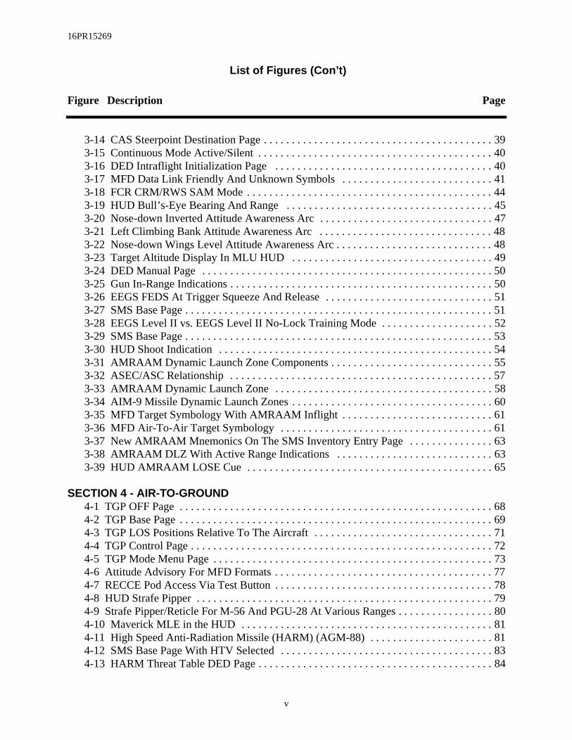
List of Figures (Con’t)
Figure Description Page
3-14 CAS Steerpoint Destination Page . . . . . . . . . . . . . . . . . . . . . . . . . . . . . . . . . . . . . . . . . 393-15 Continuous Mode Active/Silent . . . . . . . . . . . . . . . . . . . . . . . . . . . . . . . . . . . . . . . . . . 403-16 DED Intraflight Initialization Page . . . . . . . . . . . . . . . . . . . . . . . . . . . . . . . . . . . . . . . 403-17 MFD Data Link Friendly And Unknown Symbols . . . . . . . . . . . . . . . . . . . . . . . . . . . 413-18 FCR CRM/RWS SAM Mode . . . . . . . . . . . . . . . . . . . . . . . . . . . . . . . . . . . . . . . . . . . . 443-19 HUD Bull’s-Eye Bearing And Range . . . . . . . . . . . . . . . . . . . . . . . . . . . . . . . . . . .3-20 Nose-down Inverted Attitude Awareness Arc . . . . . . . . . . . . . . . . . . . . . . . . . . . . 3-21 Left Climbing Bank Attitude Awareness Arc . . . . . . . . . . . . . . . . . . . . . . . . . . . . . 3-22 Nose-down Wings Level Attitude Awareness Arc . . . . . . . . . . . . . . . . . . . . . . . . . .3-23 Target Altitude Display In MLU HUD . . . . . . . . . . . . . . . . . . . . . . . . . . . . . . . . . . .3-24 DED Manual Page . . . . . . . . . . . . . . . . . . . . . . . . . . . . . . . . . . . . . . . . . . . . . . . . .503-25 Gun In-Range Indications . . . . . . . . . . . . . . . . . . . . . . . . . . . . . . . . . . . . . . . . . . . .3-26 EEGS FEDS At Trigger Squeeze And Release . . . . . . . . . . . . . . . . . . . . . . . . . . .3-27 SMS Base Page . . . . . . . . . . . . . . . . . . . . . . . . . . . . . . . . . . . . . . . . . . . . . . . . . . . . 513-28 EEGS Level II vs. EEGS Level II No-Lock Training Mode . . . . . . . . . . . . . . . . . . .3-29 SMS Base Page . . . . . . . . . . . . . . . . . . . . . . . . . . . . . . . . . . . . . . . . . . . . . . . . . . . . 533-30 HUD Shoot Indication . . . . . . . . . . . . . . . . . . . . . . . . . . . . . . . . . . . . . . . . . . . . . . 43-31 AMRAAM Dynamic Launch Zone Components . . . . . . . . . . . . . . . . . . . . . . . . . . . 3-32 ASEC/ASC Relationship . . . . . . . . . . . . . . . . . . . . . . . . . . . . . . . . . . . . . . . . . . . . 3-33 AMRAAM Dynamic Launch Zone . . . . . . . . . . . . . . . . . . . . . . . . . . . . . . . . . . . . . 3-34 AIM-9 Missile Dynamic Launch Zones . . . . . . . . . . . . . . . . . . . . . . . . . . . . . . . . . .3-35 MFD Target Symbology With AMRAAM Inflight . . . . . . . . . . . . . . . . . . . . . . . . . . .3-36 MFD Air-To-Air Target Symbology . . . . . . . . . . . . . . . . . . . . . . . . . . . . . . . . . . . . 3-37 New AMRAAM Mnemonics On The SMS Inventory Entry Page . . . . . . . . . . . . . .3-38 AMRAAM DLZ With Active Range Indications . . . . . . . . . . . . . . . . . . . . . . . . . . . 3-39 HUD AMRAAM LOSE Cue . . . . . . . . . . . . . . . . . . . . . . . . . . . . . . . . . . . . . . . . . .
SECTION 4 - AIR-TO-GROUND4-1 TGP OFF Page . . . . . . . . . . . . . . . . . . . . . . . . . . . . . . . . . . . . . . . . . . . . . . . . . . . . . 684-2 TGP Base Page . . . . . . . . . . . . . . . . . . . . . . . . . . . . . . . . . . . . . . . . . . . . . . . . . . . .. . 694-3 TGP LOS Positions Relative To The Aircraft . . . . . . . . . . . . . . . . . . . . . . . . . . . . . .4-4 TGP Control Page . . . . . . . . . . . . . . . . . . . . . . . . . . . . . . . . . . . . . . . . . . . . . . . . . . . . 724-5 TGP Mode Menu Page . . . . . . . . . . . . . . . . . . . . . . . . . . . . . . . . . . . . . . . . . . . . . . .4-6 Attitude Advisory For MFD Formats . . . . . . . . . . . . . . . . . . . . . . . . . . . . . . . . . . . . .4-7 RECCE Pod Access Via Test Button . . . . . . . . . . . . . . . . . . . . . . . . . . . . . . . . . . . .4-8 HUD Strafe Pipper . . . . . . . . . . . . . . . . . . . . . . . . . . . . . . . . . . . . . . . . . . . . . . . . . .. 794-9 Strafe Pipper/Reticle For M-56 And PGU-28 At Various Ranges . . . . . . . . . . . . . . .4-10 Maverick MLE in the HUD . . . . . . . . . . . . . . . . . . . . . . . . . . . . . . . . . . . . . . . . . . .4-11 High Speed Anti-Radiation Missile (HARM) (AGM-88) . . . . . . . . . . . . . . . . . . . . . 4-12 SMS Base Page With HTV Selected . . . . . . . . . . . . . . . . . . . . . . . . . . . . . . . . . . .4-13 HARM Threat Table DED Page . . . . . . . . . . . . . . . . . . . . . . . . . . . . . . . . . . . . . . .
v

16PR15269
List of Figures (Con’t)
Figure Description Page
4-14 HARM Manual Threat Pages . . . . . . . . . . . . . . . . . . . . . . . . . . . . . . . . . . . . . . . . . . . . 844-15 HARM Mode Menu Page . . . . . . . . . . . . . . . . . . . . . . . . . . . . . . . . . . . . . . . . . . . . . . . 854-16 HARM POS WPN Delivery Page . . . . . . . . . . . . . . . . . . . . . . . . . . . . . . . . . . . . . . . . 874-17 HUD POS Mode Symbology . . . . . . . . . . . . . . . . . . . . . . . . . . . . . . . . . . . . . . . . . . . . 894-18 ALIC Video Display Before Hand-Off . . . . . . . . . . . . . . . . . . . . . . . . . . . . . . . . . . . . 904-19 ALIC Video Display After Hand-Off . . . . . . . . . . . . . . . . . . . . . . . . . . . . . . . . . . . . . . 914-20 HARM HAS Mode HUD Symbology . . . . . . . . . . . . . . . . . . . . . . . . . . . . . . . . . . . . . 924-21 DED SEAD Destination Page . . . . . . . . . . . . . . . . . . . . . . . . . . . . . . . . . . . . . . . . . . . 934-22 DED Steerpoint Page . . . . . . . . . . . . . . . . . . . . . . . . . . . . . . . . . . . . . . . . . . . . . . . . . . 944-23 HSD SEAD Target Display . . . . . . . . . . . . . . . . . . . . . . . . . . . . . . . . . . . . . . . . . . . . . 954-24 Data Link SEAD Character Code Display . . . . . . . . . . . . . . . . . . . . . . . . . . . . . . . . . . 954-25 SEAD DL Page . . . . . . . . . . . . . . . . . . . . . . . . . . . . . . . . . . . . . . . . . . . . . . . . . . . . . . . 974-26 SEAD Message Transmission . . . . . . . . . . . . . . . . . . . . . . . . . . . . . . . . . . . . . . . . . . . 98
SECTION 5 - DEFENSIVE AVIONICS5-1 HSD Threat Ring Display . . . . . . . . . . . . . . . . . . . . . . . . . . . . . . . . . . . . . . . . . . . . . . 1015-2 DED INTG Pages . . . . . . . . . . . . . . . . . . . . . . . . . . . . . . . . . . . . . . . . . . . . . . . . . . . . . 1025-3 FCR AIFF Jamming Indications . . . . . . . . . . . . . . . . . . . . . . . . . . . . . . . . . . . . . . . . . 102
vi

16PR15269
List of Tables
Table Description Page
SECTION 1 - GENERAL1-1 ARC-186R 8.33 KHz Frequency Channel Spacing . . . . . . . . . . . . . . . . . . . . . . . . . . . . . 41-2 CMFD Color Palette . . . . . . . . . . . . . . . . . . . . . . . . . . . . . . . . . . . . . . . . . . . . . . . . . . . . . 51-3 Colored Symbol Default Colors . . . . . . . . . . . . . . . . . . . . . . . . . . . . . . . . . . . . . . . . . . . . 61-4 Symbology And MFD Rocker Switches . . . . . . . . . . . . . . . . . . . . . . . . . . . . . . . . . . . . . 91-5 MFD Format Types . . . . . . . . . . . . . . . . . . . . . . . . . . . . . . . . . . . . . . . . . . . . . . . . . . . . . 9
SECTION 2 - NAVIGATION2-1 NVP Pilot Fault List . . . . . . . . . . . . . . . . . . . . . . . . . . . . . . . . . . . . . . . . . . . . . . . . . . . . 24
SECTION 3 - AIR-TO-AIR3-1 AMRAAM Missile ID Assignment . . . . . . . . . . . . . . . . . . . . . . . . . . . . . . . . . . . . . . . . 64
SECTION 4 - AIR-TO-GROUND4-1 Mark-84 CEP Improvement Percentages . . . . . . . . . . . . . . . . . . . . . . . . . . . . . . . . . . . . 984-2 CBU-87 CEP Improvement Percentages . . . . . . . . . . . . . . . . . . . . . . . . . . . . . . . . . . . . 99
vii

16PR15269
THIS PAGE INTENTIONALLY LEFT BLANK
viii

16PR15269
INTRODUCTION
Operational Flight Program (OFP) M2/M2+ is a Modular Mission Computer (MMC)based software update that will field in the late 2000 time frame. The software update is primarilya common set of new capabilities for the European Participating Air Forces (EPAF) MLU and theUSAF Block 50 aircraft. However, because there are a few minor differences, the EPAF versionof the software update is referred to as M2 and the USAF version is M2+. This documentaddresses the M2 update.
The M2 core avionics operational flight program (OFP) has incorporated numerous sys-tems and mechanization changes that expand the current MLU aircraft tactical capability. Newcapabilities include Navigation and Targeting Pod Interfaces, Generic Recce II, Digital TerrainSystem (DTS) Phase II enhancements, Autonomous Air Combat Maneuvering Instrumentation(Autonomous ACMI), Improved Data Modem (IDM), Automatic Target Hand-off System(ATHS), and the AGM-88 High Speed Anti-Radiation Missile (HARM).
The Navigation and Targeting Pod Interfaces were integrated to support the Royal Nether-lands Air Force (RNLAF) Navigation and Targeting FLIR pod procurement program. The inter-faces support full Block 40T5 LANTIRN capabilities. Recce II supports a Royal Danish AirForce (RDAF) Reconnaissance Pod procurement program. It provides for operational control ofRecce pod sensors and video recording equipment. DTS Phase II enhances the overall perfor-mance and accuracy of the Terrain Referenced Navigation (TRN), Obstacle Warning and Cueing(OW/C), Predictive Ground Collision Avoidance (PGCAS), and Data Base Terrain Cueing(DBTC) functions that were integrated into the Block 50/MLU MMC M1 Tape. In addition, DTSPhase II includes a Passive Ranging (PR) feature and integration of TRN with the aircraft MasterNavigation Filter (MNF). Autonomous ACMI provides for in-flight recording and storage of F-16mux bus data that will be used for mission de-briefing. The IDM ATHS provides the ability totransmit an "On-station" message and receive a "Mission Update (CAS 9-line brief)" via theIDM. The AGM-88 HARM is an air-to-surface missile designed to suppress RF (Radio Fre-quency)-based enemy air defenses.
The M2 OFP also includes significant enhancements to the Hands-on control functions,Color Multifunction Display (CMFD) symbology, Horizontal Situation Display (HSD) format,Advanced Identification Friend or Foe (AIFF), and Head-up Display (HUD) symbology. Many ofthese enhancements resulted from pilot feedback during the M1 flight testing activities. The purpose of this guide is to facilitate a basic understanding of the capabilities and cockpit mechanizations in the M2 software update. To keep the contents of the document short and con-cise, previous knowledge of the MLU cockpit operation is assumed. Each capability and cockpit mechanization is identified with a title and an RDP number. The RDPs (Requirements Definition Packages) are maintained by Lockheed Martin Aeronautics Company (LM Aero) and contain detailed design requirements for each capability. If additional details are required concerning a particular capability consult 16PR13133, F-16 Avionics Systems Manual (MLU M2), T.O. 1F-16AM-34-1-1, Avionics and Non-Nuclear Weapons Delivery Flight Manual, or contact LM Aero Pilot Vehicle Interface at 817-777-8732.
1

16PR15269
THIS PAGE INTENTIONALLY LEFT BLANK
2

16PR15269
e. Itoblem
MCelec-RM,.
rected.ks to
thsnterna- in5-kHzchannel(CNI) digitesired
SECTION 1 - GENERAL
This section discusses the following topics:
• Core Avionics Provisions• Avionics Selection After MMC Power Cycle• Jettison Delay For 600 Gallon Tanks• AN/ARC-186R VHF Radio 8.33 kHz Channel Spacing• Autonomous ACMI• Color Display Optimization • Color Data Linked Information Outside The HSD FOV• MFDS Horizon Line Incorrect When Inverted• MFD Contrast/Brightness Control• MFD Display Gain Control Option Incorporation• Reduce Size Of FCR Symbology• GPS Time Available On BUS/GPS Time Use
Core Avionics Provisions (RDP-052)M2 incorporates changes resulting from the USAF Block 50T5 baseline softwar
updates the Mulitplexed (MUX) duty cycle and incorporates flight test generated System PrAnomaly Reports (SPARs) that have been resolved.
Avionics Selection After MMC Power Cycle (RDP-1367)All avionics and weapon selections should come up “last left” after an airborne M
power cycle (auto restart, manual MMC power cycle, or aircraft power cycle). All avionics stions should come up “last left” and weapon power selections should be “Off” (AIM-9 WAAGM-65 POWER OFF, PENGUIN POWER OFF) after an MMC power cycle on the ground
Jettison Delay For 600 Gallon Tanks (RDP-2000)Stores weight and drag values for the 370 and 600 gallon tanks have been cor
Additionally, a 150-ms delay has been implemented in the jettison of the 600-gallon tanreduce the potential of tank-to-tank collision after being jettisoned.
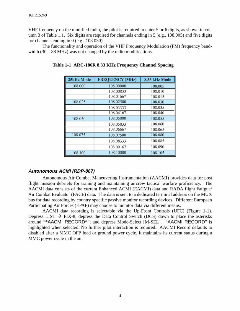
AN/ARC-186R VHF Radio 8.33 kHz Channel Spacing (RDP-1701)The Very High Frequency (VHF) Amplitude Modulation (AM) radio channel bandwid
have been decreased from 25-kHz to 8.33-kHz (5-kHz pseudo-channels) to support the Itional Civil Aviation Organization’s (ICAO’s) effort to reduce VHF frequency saturationEurope. The bandwidth reduction provides two additional channels between the original 2band spacing as shown in columns 1 and 2 of Table 1-1. To accommodate the reduced spacing, the 1553 Mux bus terminal interface, the Communication, Navigation and IFF Data Entry Display (DED) and COMM 2 DED pages have been modified (a thousandthsadded) to support DTC and manual loading of the 8.33-kHz channels. To specify the d
3
16PR15269
ostTheue/
e MUXopean
-1).risks
lts toring a
VHF frequency on the modified radio, the pilot is required to enter 5 or 6 digits, as shown in col-umn 3 of Table 1.1. Six digits are required for channels ending in 5 (e.g., 108.005) and five digitsfor channels ending in 0 (e.g., 108.030).
The functionality and operation of the VHF Frequency Modulation (FM) frequency band-width (30 – 88 MHz) was not changed by the radio modifications.
Table 1-1 ARC-186R 8.33 KHz Frequency Channel Spacing
Autonomous ACMI (RDP-867)Autonomous Air Combat Maneuvering Instrumentation (AACMI) provides data for p
flight mission debriefs for training and maintaining aircrew tactical warfare proficiency. AACMI data consists of the current Enhanced ACMI (EACMI) data and RADA flight FatigAir Combat Evaluator (FACE) data. The data is sent to a dedicated terminal address on thbus for data recording by country specific passive monitor recording devices. Different EurParticipating Air Forces (EPAF) may choose to monitor data via different means.
AACMI data recording is selectable via the Up-Front Controls (UFC) (Figure 1Depress LIST Å FIX-8; depress the Data Control Switch (DCS) down to place the astearound “*AACMI RECORD*”; and depress Mode-Select [M-SEL]. “AACMI RECORD” ishighlighted when selected. No further pilot interaction is required. AACMI Record defaudisabled after a MMC OFP load or ground power cycle. It maintains its current status duMMC power cycle in the air.
25kHz Mode FREQUENCY (MHz) 8.33 kHz Mode
108.000
108.025
108.050
108.075
108.100
108.005
108.065
108.060
108.055
108.040
108.035
108.030
108.015
108.010
108.105
108.090
108.085
108.080
108.00000
108.08333
108.07500
108.06667
108.05833
108.05000
108.04167
108.03333
108.02500
108.01667
108.00833
108.10000
108.09167
4

16PR15269
Figure 1-1 DED AACMI Mode Selection
Color Display Optimization (RDP-1054)In order to provide Night Vision Imaging System (NVIS) compatible Color Multi-Func-
tion Displays (CMFD), two separate backlights are used. Together the two backlights generatethe full luminance range (0.04-190 ft-lamberts). The transition between the two lamps is con-trolled internal to the CMFD. In the NVIS mode the day lamp is disabled, which forces theCMFD to use only the night (NVIS compatible) lamp. There is a slight color shift (less red) whenonly the night lamp is used.
Table 1-2 CMFD Color PaletteThe CMFD color palette is fixed and defined by the
8 colors listed in Table 1-2. (Colors in the table and illustra-tions of this book only approximate the actual display col-ors.) The color palette consists of the primary subtractivecolors and the primary additive colors plus white and gray.
The pilot has the ability to change the color of sym-bols via the Data Transfer Cartridge Loader/Reader (DTC L/R) during mission planning. Color changes are loaded intothe CMFD by depressing COLR (OSB #2) on the DTEpage. Once loaded into the aircraft, the new color table isretained through MFD power cycles until a subsequent DTCload changes the color table.
The default colors for the Rules Of Engagement(ROE) dependent color symbols are listed in (Table 1-3).
L I ST
DEST
MAN
BINGO
NAV
M ISC
DLNK
I NTG
VRP
I NS
V I P
MODE
1 2 3
4 5 6
7 8 9
R
E
0
12
MODE 12A-AXX
AACMI RECORD
MODE
X
12A-A
AACMI RECORDX
MODE 12A-A
XXAACMI RECORD
MSEL
LIST
SEQRTN
8
FIX
White
Red
Green
Cyan
Yellow
Magenta
Blue
Gray
5

16PR15269
Table 1-3 Colored Symbol Default Colors
D/LTeam Member
D/L Friendly
D/L Unknown
D/LTeam Member
Outside FOV
D/LUnknown
Outside FOV
Unknown System
Track Target
Unknown System
Track Target
(w/ Active AIM-120)
Unknown System
Track Target
(w/ AIM-120)
Nav Route
Active Nav Route
GEO Lines (1-4)
Preplanned Threat
Preplanned Threat
(w/ Ownship in
Lethal Range)
3
20
6
23
2
15
2
2
16
16
16
Cyan
Cyan
Green
Yellow
Yellow
Yellow
Yellow
Magenta
Red
Red
Gray
Gray
White
6

16PR15269
If thed yel-distin-
Color Data Linked Information Outside The HSD FOV (RDP-884)When Data Link (DL) team members fall outside the Horizontal Situation Display (HSD)
Field Of View (FOV), they are represented by a cyan filled triangle at azimuth on the outer rangering of the HSD (Figure 1-2). The team member’s number is displayed above the triangle.team member has a Target Of Interest (TOI) outside the HSD FOV, it is displayed as a fillelow triangle at azimuth on the outer range ring with the team member number above it to guish which team member has bugged that target.
Figure 1-2 Data Linked Targets Outside HSD FOV
GAIN SYM
BRT CON
SWAPSMS DTE S-J
60
HSD
F
Z
DCPL CNTLDEP
47210
S
F
AP
P
x
3
X
3
15
20
3
2
2
DL TEAM MEMBER
OUTSIDE OF HSD FOV
DL TEAM MEMBER'S TOI
OUTSIDE OF HSD FOV
7

16PR15269
MFD Horizon Line Incorrect When Inverted (RDP-1246)The Horizon line operation displayed on the Multi-Function Display (MFD) formats has
been modified such that when the aircraft is flying inverted and pitching toward the ground, thehorizon line on the MFD moves toward the bottom of the MFD display (Figure 1-3). The horizonline now indicates the true direction to the horizon.
Figure 1-3 MFD Horizon Line Movement during Inverted Flight
GAIN SYM
BRT CON
GAIN SYM
BRT CON
SWAP DCLT
10
FCR
AGR CNTLOVRD
P
R
S
P
T
G
T
C
Z
NOT SOI
A
3
W
RDY
SWAP DCLT
10
FCR
AGR CNTLOVRD
P
R
S
P
T
G
T
C
Z
NOT SOI
A
3
W
RDY
HORIZON LINE
HORIZON
8

16PR15269
MFD Contrast/Brightness Control (RDP-1160)When swapping MFD formats (OSB #15) in either the forward or aft station, brightness
and contrast settings are retained per format when transitioning to the new display. Symbol inten-sity is saved on a per channel basis per format such that symbol intensity changes made to the aftleft display will affect the forward left display. The same holds true for the right displays.
Three unique display types are used on the MFDs: text, video, and symbols. The MFDrocker switches that affect text, video and symbols as defined in Table 1-4.
Table 1-4 Symbology And MFD Rocker Switches
NOTE: MFD Symbol Intensity affects TGP and Fire Control Radar (FCR) Video via M1 documentation. The M1 baseline provides for feedback of MFD symbol intensity to the FCR and to the TGP in an effort to match symbol intensity of the MFD generated symbology with that of the FCR and TGP
symbology.
Table 1-5 divides the formats into Video and Non-Video displays:
Table 1-5 MFD Format Types
Things You Seeon an MFD
MFD Rocker Switches
Video Generated Symbols
TEXT
VIDEO
MFD Generated Symbols
BRT SYMCON
x
x
x(See Note)x
x
x
x
x
x
x
x
NA
VIDEOFORMATS
NON-VIDEOFORMATS
FLIR TEST
FCR
SMSTGP
HSD
BLANKTFR
FLCSWPN
DTERCCE
9

16PR15269
Symbol Intensity, Brightness and Contrast (SBC) values for each Format (Figure 1-4) aresaved as follows:
1) One symbol intensity value is saved for all MFD symbols which appearfor all non-video formats
2) A different symbol intensity value is saved for each video format3) One brightness value is saved for all non-video formats4) A different brightness value is saved for each video format5) One contrast value is saved for all non-video formats6) A different contrast value is saved for each video format
Figure 1-4 MFD Symbol Intensity, Brightness, And Contrast Controls
GAIN SYM
BRT CON
BRIGHTNESS VALUESARE SAVED FOR ALLNON-VIDEO FORMATSAND EACH VIDEO FORMAT
SYMBOLOGY INTENSITYVALUES ARE SAVED ONCEFOR ALL NON-VIDEO FORMATS AND FOR EACHVIDEO FORMAT.
CONTRAST VALUES ARESAVED ONCE FOR ALLNON-VIDEO FORMATSAND EACH VIDEO FORMAT.
10
16PR15269
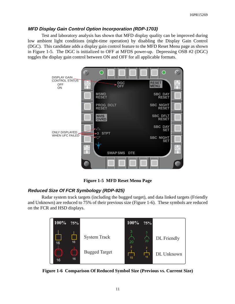
MFD Display Gain Control Option Incorporation (RDP-1703)Test and laboratory analysis has shown that MFD display quality can be improved during
low ambient light conditions (night-time operation) by disabling the Display Gain Control(DGC). This candidate adds a display gain control feature to the MFD Reset Menu page as shownin Figure 1-5. The DGC is initialized to OFF at MFDS power-up. Depressing OSB #2 (DGC)toggles the display gain control between ON and OFF for all applicable formats.
Figure 1-5 MFD Reset Menu Page
Reduced Size Of FCR Symbology (RDP-925)Radar system track targets (including the bugged target), and data linked targets (Friendly
and Unknown) are reduced to 75% of their previous size (Figure 1-6). These symbols are reducedon the FCR and HSD displays.
Figure 1-6 Comparison Of Reduced Symbol Size (Previous vs. Current Size)
GAIN SYM
BRT CON
GAIN SYM
BRT CON
SWAPSMS DTE
RESET
MENUDGC
OFF
SBC DAY
RESET
3 STPT
MSMD
RESET
W
SBC NIGHT
SET
SBC DAY
SET
SBC DFLT
RESET
SBC NIGHT
RESET
NVIS
OVRD
PROG DCLT
RESET
DISPLAY GAINCONTROL STATUS
ONLY DISPLAYEDWHEN UFC FAILED
OFFON
100% 75%
16
16 16
16
System Track
Bugged Target
3
20
100%
3
20
75%
2
15
2
15DL Unknown
DL Friendly
11

16PR15269
GPS Time Available On Bus/GPS Time Use (RDP-1159)The pilot has the option to select/deselect Global Positioning System (GPS) time as sys-
tem time when GPS time is available. The GPS label adjacent to the system time on the DEDTime page (Figure 1-7) indicates that GPS time is the source of system time. The source of sys-tem time initializes to GPS at power-up on the ground. The GPS label will not appear until theGPS time is valid. GPS time is deselected by depressing the DCS to sequence (SEQ) with GPStime selected. When GPS time is deselected, GPS is turned off, or GPS time becomes invalid, theGPS label is blanked and system time can be entered on the TIME or CRUS TOS page. Whentime is entered on the CRUS TOS page, GPS time is deselected.
Figure 1-7 DED TIME Page
The current month, day , and year have been added to the TIME page.
TIME
GPS
MM/DD/ YY
DELTA TOS
HACK
02/ 07/ 99
10: 36: 27SYSTEM
16: 32: 43
00: 03: 46X X
12
16PR15269
flightund in Refer-ce of(OW/s and. The
SECTION 2 - NAVIGATION
This section introduces the following Navigation enhancements:
• Digital Terrain System (DTS) Phase II • DBTC Whiskers• Roll Stabilized DTS DBTC Cue• HSD Freeze Enhancements• HSD Declutter By Master Mode• Identify The Active Navigation Route• NVP Boresight And Faults• NVP Laser Spot Locator (LSL)• Include Current Master Mode In DTE Load• Hands-On Declutter Of HUD Symbology (Landing Phase)• Time-Over-Steerpoint (TOS) Refinements• UTM Coordinate Entry Of Up To Four Digits
Digital Terrain System (DTS) Phase II (RDP-1077)The Digital Terrain System (DTS) Phase II development and the Block 50T5 DTS
test activities have been combined to significantly improve the overall DTS performance fothe M1 OFP. DTS Phase II adds a Passive Ranging (PR) feature and improves the Terrainence Navigation (TRN) aircraft position accuracy which, in-turn enhances the performanPredictive Ground Collision Avoidance System (PGCAS), Obstacle Warning and Cueing C), and Data Base Terrain Cueing (DBTC) functions. Additional mechanization revisionfeatures have been incorporated at M2 to increase the operational utility of DTS functionschanges from M1 DTS capabilities are addressed below.
Terrain Reference Navigation (TRN) Enhancements:
1) Expanded Area of Operation: The DTS area of operation has beenincreased from 75 degrees North and South latitude to 80 degrees Northand South latitude.
2) TRN Integrated with Master Navigation Filter (MNF): The TRN functionhas been integrated with the MNF. TRN data is used as inputs to the MNFwhen GPS data fails to meet MNF processing criteria and the MNF co-variances indicate that TRN is providing more accurate data than GPS.
3) Blanking TRN Horizontal and Vertical Confidences: When TRN is inAcquisition, the TRN Horizontal and Vertical Confidences on the DEDDTS Priority page (Figure 2-1) are blanked. In M1, the TRN Horizontaland Vertical Confidences were displayed when TRN was in Acquisition.
13

16PR15269
Figure 2-1 DTS Priority Page
4) Filter Mode Expanded on DED NAV Commands Page: The master naviga-tion filter mode on the NAV Commands page has been expanded to includeDTS. In M1, the AUTO filter mode provided automatic processing ofGPS, INS data, and manual fixes for deriving the aircraft system naviga-tion solution. In M2, the DTS navigation solution replaces the system nav-igation solution (whole value replacement) when GPS data is not available.The filter mode selection rotary (AUTO, INS, Blank) is unchanged.
5) DTS Status Changes: PVI for the display of "DTSFIX" and "NO GPW" onthe HUD (Figure 2-2) has been changed. First, the "DTSFIX" mnemonichas been changed to "DTSACQ." "DTSACQ" flashes in the HUD abovethe airspeed scale, instead of top-center HUD, when TRN is in AcquisitionMode and PGCAS is not selected. If the PGCAS function is selectedbefore TRN goes into Acquisition mode, a flashing "NO GPW" is dis-played instead of "DTSACQ". Depressing Warn Reset changes the flash-ing "DTSACQ" or "NO GPW" mnemonic to a steady condition. Neither"DTSACQ" nor "NO GPW" is displayed when the INS is doing an In-Flight Alignment (IFA).
V:
H:
ACQ
200FT
1000FT
DTS 12
XX PGCAS
DBTC
OW/C
PGCAS MODE SELECT PGCAS MINIMUM
TERRAIN CLEARANCE
(50-9999FT)
HORIZONTAL
CONFIDENCE
VERTICAL
CONFIDENCE
(H, M, Blank)
(H, M, Blank)
14
16PR15269
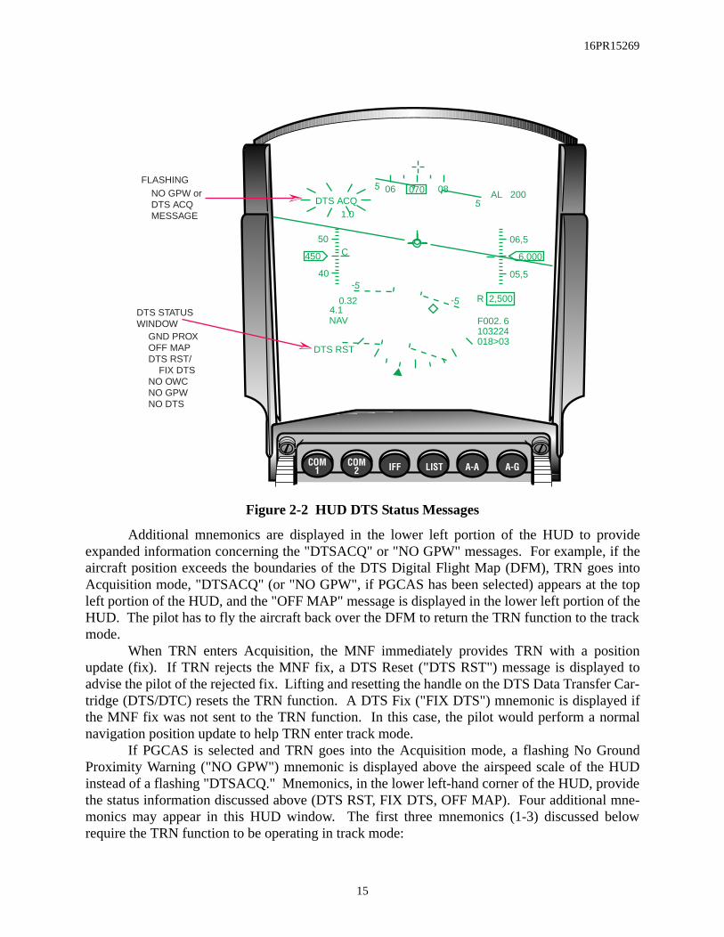
Figure 2-2 HUD DTS Status Messages
Additional mnemonics are displayed in the lower left portion of the HUD to provideexpanded information concerning the "DTSACQ" or "NO GPW" messages. For example, if theaircraft position exceeds the boundaries of the DTS Digital Flight Map (DFM), TRN goes intoAcquisition mode, "DTSACQ" (or "NO GPW", if PGCAS has been selected) appears at the topleft portion of the HUD, and the "OFF MAP" message is displayed in the lower left portion of theHUD. The pilot has to fly the aircraft back over the DFM to return the TRN function to the trackmode.
When TRN enters Acquisition, the MNF immediately provides TRN with a positionupdate (fix). If TRN rejects the MNF fix, a DTS Reset ("DTS RST") message is displayed toadvise the pilot of the rejected fix. Lifting and resetting the handle on the DTS Data Transfer Car-tridge (DTS/DTC) resets the TRN function. A DTS Fix ("FIX DTS") mnemonic is displayed ifthe MNF fix was not sent to the TRN function. In this case, the pilot would perform a normalnavigation position update to help TRN enter track mode.
If PGCAS is selected and TRN goes into the Acquisition mode, a flashing No GroundProximity Warning ("NO GPW") mnemonic is displayed above the airspeed scale of the HUDinstead of a flashing "DTSACQ." Mnemonics, in the lower left-hand corner of the HUD, providethe status information discussed above (DTS RST, FIX DTS, OFF MAP). Four additional mne-monics may appear in this HUD window. The first three mnemonics (1-3) discussed belowrequire the TRN function to be operating in track mode:
06 08070
6,000450
5
5
-5
-5
50
40
06,5
05,5
1.0
C
DTS ACQ
0.324.1NAV
DTS RST
R 2,500
AL 200
F002. 6
018>03103224
DTS STATUSWINDOW
GND PROXOFF MAPDTS RST/ FIX DTSNO OWCNO GPWNO DTS
FLASHING NO GPW orDTS ACQMESSAGE
15

16PR15269
1) "GND PROX" is displayed when PGCAS has triggered a "Break X" on theHUD and the MFDs to warn of imminent ground collision.
2) "NO OWC" indicates that the DTS obstacle warning and cueing feature isnot functional. The "NO OWC" message is inhibited for 30 seconds afterthe landing gear is up.
3) "NO GPW" is displayed when TRN is in track and PGCAS is not selected.4) "NO DTS" indicates the Digital Terrain System is not functional.
NOTE: Failure to lock the DTS/DTC in the data transfer unit will cause a
"NO DTS" message.
Expanded messages in the lower left portion of the HUD are displayed in the followingprioritized order: "GND PROX", "OFF MAP", "DTS RST", "FIX DTS", "NO OWC", "NOGPW", and "NO DTS".
Vertical Velocity Propagator (VVP): The Vertical Velocity Propagator (VVP) feature calibrates the INS estimate of aircraft ver-
tical velocity with either DTS or GPS vertical velocity data. The VVP provides enhanced inputsfor aircraft algorithms requiring accurate vertical data. The feature is automatically enabled whenthe Auto ACAL is selected for operation.
Predictive Ground Collision Avoidance System (PGCAS): The following changes were added to improve the PGCAS functions operational utility:
1) Expanded Operational Limits: Maximum calibrated airspeed limit wasincreased from 640-KCAS to 800-KCAS for the PGCAS function.
2) PGCAS Minimum Terrain Clearance (MTC) Reset: When DBTC isselected, the PGCAS MTC altitude is automatically set based on theselected DBTC Terrain Clearance Height (TCH), otherwise, the PGCASalgorithm uses the selected MTC altitude entered on the DTS Prioritypage. When DBTC has been selected and is subsequently de-selected, thePGCAS algorithm continues to use the MTC altitude defined by the DBTCTCH selection until the aircraft climbs above the TCH based altitude.Once the MTC altitude has been exceeded, the MTC will reset to the alti-tude selection on the DTS Priority page. In M1, the MTC was immediatelyreset to the selection on the PGCAS page when DBTC was deselected.
3) Revised PGCAS MTC Altitudes: MTC altitudes were modified for M2.The MTC is set to 25 percent of the ALOW or 50 feet, whichever isgreater. If ALOW is set to zero, the MTC is set to 250 feet. MTC entriesmade on the DTS Priority page override the ALOW-based MTC. TheMTC remains at its last-left value during in-flight MMC power cycles.MMC power cycles on the ground reset the MTC to the ALOW-basedvalue.
4) Automatic Fifty-Foot MTC: In M2, the 50-foot MTC setting is automati-cally selected when the A-G weapon delivery mode is CCIP or Strafe. The
16

16PR15269
PGCAS predicted recovery curve for M2 was changed to a 5-G pull-upinstead of the M1 4-G pull-up and the MFDS Break X display was changedto 1.1 seconds time-to-go to pull-up for M2 instead of 2 seconds in M1.These changes were made to reduce the number of nuisance warnings.
PGCAS advisories are affected by the accuracy of the DFM loaded into the DTS/DTC. A50 feet MTC entry does not guarantee that PGCAS provides adequate protection to a 50 feet MTCfor any particular mission. PGCAS advisories are also based on the current stores loading and ifthe wrong stores and/or store quantities, or a manual fuel transfer is accomplished causing anasymmetrical fuel loading, PGCAS effectiveness may be impacted.
Obstacle Warning and Cueing (OW/C):OW/C is initialized to the enabled state and may be disabled/enabled on the DTS Priority
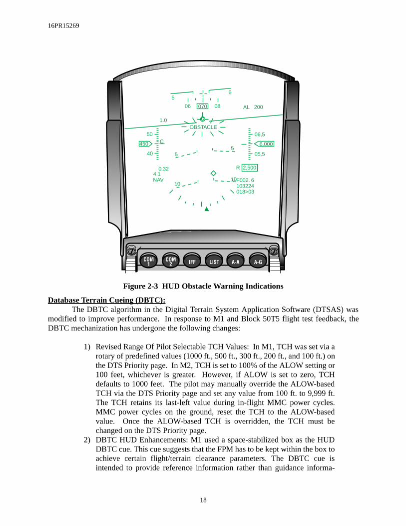
page. OW/C provides a warning whenever a significant obstacle is detected in the OW/C scanarea near the predicted flight path of the aircraft. A significant obstacle is one where the obstacleheight plus the clearance height is greater than the projected flight path of the aircraft. A flashing"OBSTACLE" is displayed in the top, center of the HUD (Figure 2-3) to warn the pilot of any sig-nificant obstacles. M2 modified the obstacle clearance height to be 75% of the DBTC TCH dur-ing DBTC operation. When DBTC is not selected, a default value of 500 feet is used.
For aircraft bank angles greater than 90 degrees, OW/C advisories are not valid eventhough they are displayed. The pilot should visually verify adequate clearance to avoid towersand their associated guy wires.
17
16PR15269
Figure 2-3 HUD Obstacle Warning Indications
Database Terrain Cueing (DBTC):The DBTC algorithm in the Digital Terrain System Application Software (DTSAS) was
modified to improve performance. In response to M1 and Block 50T5 flight test feedback, theDBTC mechanization has undergone the following changes:
1) Revised Range Of Pilot Selectable TCH Values: In M1, TCH was set via arotary of predefined values (1000 ft., 500 ft., 300 ft., 200 ft., and 100 ft.) onthe DTS Priority page. In M2, TCH is set to 100% of the ALOW setting or100 feet, whichever is greater. However, if ALOW is set to zero, TCHdefaults to 1000 feet. The pilot may manually override the ALOW-basedTCH via the DTS Priority page and set any value from 100 ft. to 9,999 ft.The TCH retains its last-left value during in-flight MMC power cycles.MMC power cycles on the ground, reset the TCH to the ALOW-basedvalue. Once the ALOW-based TCH is overridden, the TCH must bechanged on the DTS Priority page.
2) DBTC HUD Enhancements: M1 used a space-stabilized box as the HUDDBTC cue. This cue suggests that the FPM has to be kept within the box toachieve certain flight/terrain clearance parameters. The DBTC cue isintended to provide reference information rather than guidance informa-
06 08070
6,000450
55
5 5
50
40
06,5
05,5
1.0
C
0.324.1NAV
R 2,500
AL 200
F002. 6
018>03103224
10 10
OBSTACLE
18

16PR15269
tion. As a result, M2 changed the DBTC steering cue to a set of chevrons,or "whiskers" spaced 30-mr apart (See RDP-1510), with the longest "whis-kers" indicating up (Figure 2-4). The steering cue moves vertically withrespect to the Flight Path Marker (FPM) to indicate a climb or descent tomaintain the selected TCH. The steering cue is roll-stabilized (no longerblanked when exceeding 120 degrees of bank) on the HUD (See RDP-1244) and positioned based on a maximum -0.9-G pushover or 2.0-G incre-mental pull-up maneuver. A TCH caret is positioned on the HUD altitudescale when the TCH is within the displayed scale. When the Barometric(BARO) scale is displayed, the TCH AGL caret is adjusted to reflect theequivalent BARO altitude.The DBTC low terrain clearance ("LO TC") advisory is displayed in thecenter of the HUD FOV when radar altitude is below 75% of the selectedTCH. The DBTC cue and "LO TC" advisory are blanked when either thetotal INS velocity or the calibrated airspeed is less than 300 knots. DBTC is limited to 640 knots unlike other DTS functions that are clearedto 800 knots.
Figure 2-4 DBTC And Status HUD Cues
Note:The digital terrain elevation and obstacle databases do not account for foliage.
06 08070
450
55
5 5
50
40 2
4
1.0
G
0.324.1NAV
AL 200
F002. 6
018>03103224
10 10
LO TC
15
10
8
6
DBTC STEERING CUE
TERRAIN CLEARANCEHEIGHT (TCH) CARET
WARNING MESSAGE
19

16PR15269
Passive Ranging:The Passive Ranging (PR) function is a new M2 DTS capability that provides the pilot
with a back-up bombing sensor option to determine the range to a ground target with little or noRF emissions. Passive Ranging has two submodes with the appropriate submode automaticallycommanded by the avionics system based on the current Air-to-Ground (A-G) weapon deliverymode. Horizontal Range Known (HR) is used in the A-G preplanned modes (CCRP, LADD, EO-PRE). HR requires the avionics system to pass the target horizontal range X and Y to the DTS,which then returns the target elevation. The avionics system uses target elevation to determine theHeight Above Target (HAT) and then slant range. The other submode, LOS Known, is used forthe visual A-G deliveries modes (CCIP, DTOS, EO-VIS) which normally use AGR for rangingdata. The target LOS is sent to the DTS which uses target elevation, range X, Y, and Z, plus targetlatitude and longitude to compute slant range.
Passive Ranging is selected on the FCR AGR page (OSB #6). The Backup Bombing Sen-sor (BBS) rotary (Figure 2-5) is BARO, PR, and RALT. BBS defaults to BARO on power-up.When DTS/DTC is not operational, the system reverts to BARO and removes PR from the BBSrotary. The pilot may select RALT, provided the radar altimeter is operational. When PR is theselected option and the DTS/DTC is no longer operational, BBS changes to BARO.
Figure 2-5 FCR AGR Page
PR is limited to a 10-km (5.4-nm) range because of the manner in which the DTS scansthe DFM stored in the DTS/DTC. PR is not available when:
1) TRN is in ACQ mode.
GAIN SYM
BRT CON
SWAP DCLT
10
FCR
AGR CNTLOVRD
P
R
S
P
T
G
T
C
Z
NOT SOI
A
3
W
RDY
BACKUP BOMBING
SENSOR ROTARY
BARO
PR
RALT
20

16PR15269
regis-
bank
SOI),D about
tabilize
2) The aircraft total inertial velocity is above 800 KCAS. 3) DTS status is "NO DTS" or "OFF MAP". 4) The aircraft approaches the edge of the DFM and sufficient digital data is
not available to support PR.
DBTC Whiskers (RDP-1510)DBTC uses the Digital Terrain Elevation Data (DTED), obstacle database stored in the
DTS/DTC and aircraft state to provide a vertical steering cue on the HUD. The vertical steeringcue, “Whiskers”, (> <) assists in flying a smooth, well-damped trajectory over accurately tered terrain and obstacles.
Roll Stabilized DTS DBTC Cue (RDP-1244)The DTS DBTC cue is roll stabilized on the HUD (Figure 2-6) and is displayed at all
angles.
Figure 2-6 Roll Stabilized DBTC Cue
HSD Freeze Enhancements (RDP-1053)When the Horizontal Situation Display (HSD) is selected as the Sensor of Interest (
Depress and Release (D&R) OSB #7 (Freeze (FZ)) on the HSD Base page, freezes the HSthe cursor position. Upon entering freeze, the HSD utilizes the centered format to ground sabout the cursor position at the center of the display (Figure 2-7).
06 08070
450
55
5 5
50
40 2
4
1.0
G
0.324.1NAV
AL 200
F002. 6
018>03103224
10 10
15
10
8
6
DBTC STEERING CUE
06
08
070
450
50
40
24
1.0
G
0.32
4.1NAV
AL 200
F002. 6
018>03103224
15
10
86
PITCH BARS
55
5 5
10 10
BANK ANGLE INDICATOR
21

16PR15269
Figure 2-7 HSD In Freeze Mode (SOI)
When the HSD is not the SOI, D&R of FZ (OSB #7) freezes the HSD about the ownshipposition (Figure 2-8). Upon entering freeze, the HSD utilizes the centered format to ground-stabi-lize the instantaneous ownship position at the center of the display.
Figure 2-8 HSD In Freeze Mode (Not SOI)
GAIN SYM
BRT CON
SWAPSMS DTE S-J
60
F
Z
HSD
DCPL CNTLDEP
35210
3
20
GAIN SYM
BRT CON
SWAPSMS DTE S-J
40
HSD
DCPL CNTLDEP
35210
3
20
F
Z
GAIN SYM
BRT CON
GAIN SYM
BRT CON
SWAPSMS DTE S-J
40
HSD
F
Z
DCPL CNTLDEP
35210
3
20
22

16PR15269
While the HSD is in Freeze, data in steerpoints 1-99 are frozen; expand and couple/decouple are disabled. The ownship symbol and accompanying radar field-of-view move on thefrozen map. The aircraft symbol can be flown off the frozen map or can disappear due to differentrange scales selected with respect to the ground-stabilized center of the display format. HSD cur-sors, if available, can also be slewed on the map to control the Bump Range capability.
Range rings and the magnetic North pointer are displayed in Freeze if selected on theHSD Control page. When in Freeze, if the range rings and magnetic North pointer are not dis-played, RINGS (OSB #10) may be selected for display via the Control page. Upon exiting HSDFreeze, the range rings and magnetic North pointer will continue to be displayed. If the HSD wasin the depressed format before entering Freeze, upon exiting Freeze, the HSD changes back to thedepressed format and the range scale changes back to the corresponding range.
The Increment/Decrement (INC/DEC) Range symbols are displayed in HSD Freeze pageat OSBs #19 and #20. D&R of OSB #19 decreases the range scale by one setting. D&R of OSB#20 increases the range scale by one setting. Bump Range is available in Freeze only when theHSD is the SOI (HSD cursors are displayed). When Freeze is entered and the HSD is not the SOI,the HSD can be selected as the SOI and the HSD cursors will initialize in the center of the displayformat.
HSD Declutter By Master Mode (RDP-972)The pilot has the ability to set HSD Control page options (Figure 2-9) for each master
mode during mission planning and load them into the aircraft via the Data Transfer Equipment(DTE). When the pilot sets the display parameters on the HSD Control page in the aircraft, theseparameters are retained as last left upon reentering the master mode in which they were set. Anyitems, which are decluttered on the HSD Control page, are saved by master mode.
Figure 2-9 HSD Control Page
GAIN SYM
BRT CON
GAIN SYM
BRT CON
SWAPSMS DTE S-JHSD
PRE CNTLFCR
LINE3
LINE2
LINE1
ADLNK
GDLNK
NAV2
NAV1
CRPCAI FF
RINGS
LINE4
SA6
5
W
NAV3
23

16PR15269
high- passed
Identify The Active Navigation Route (RDP-1002)The active Navigation (NAV) route is defined as the NAV route containing the currently
selected steerpoint. Separate colors/intensities can be loaded for the active NAV route and theinactive NAV routes separately. White is the default for the active NAV route and gray is thedefault for the inactive NAV routes (Figure 2-9).
NVP Boresight And Faults (RDP-1169)The FLIR Boresight (BSGT) OSB #10 on the FLIR Base page (Figure 2-10) allows selec-
tion/deselection of the Navigation Pod (NVP) boresight mode. The mnemonic “BSGT” is lighted when the boresight mode is selected. When “BSGT” is selected, cursor slews areto the NVP to adjust the FLIR video to the outside world.
Figure 2-10 NVP FLIR Base Page (Above 1,200 Feet)
Five new NVP faults have been added to the Pilot Fault List (PFL) (Table 2-1).
Table 2-1 NVP Pilot Fault List
GAIN SYM
BRT CON
SWAP DCLTFLIR
W
SMS
FLIR BORESIGHT
SELECT
OPER OFF
BHOT
LSL
STBY
AR
BSGTGRAY
2000
LSL
ON
C450
OPER
88 G
44 L
LSL
SPI
STBY
110
SWAP DCLTFLIR SMS
PFLMessage Fault NameTest No.
003
006
010
Environmental Control Unit Fail
NVP BUS FAILFINS Fail
NVP BUS Fail
007
NVP LSL FAIL*
NVP FAIL*
NVP TEMP*
NVP FLIR FAIL*
NVP ECU FAIL*
039
008
Coolant Temperature Warning
Pod Control Computer Fail
LSL Fail (* Indicates new PFLs)
24

16PR15269
de iny the
lude
NVP Laser Spot Locator (RDP-1171)The capability to locate laser designated points was added to the NVP. Laser Spot Locator
(LSL) detected points can be displayed on the HUD with or without NVP video. No automatictargeting data is computed for these points. The LSL is controlled via the NVP Base page (Figure2-11). OSB #2 (LSL OFF/WAIT/ON) commands the LSL On or Off. After depressing OSB #2when the LSL is Off, the LSL WAIT label is displayed for approximately two minutes while theLSL powers-up. The OSB #2 label changes to LSL ON when the LSL system is powered up andOSBs #8 and #19 labels appear on the FLIR Video page. OSB #8 (LSL STBY/RDY) commandsthe LSL mode to standby or ready. OSB #19 selects the LSL scan pattern to Slave-to-SPI (LSLSPI) or Search (LSL SRCH).
Figure 2-11 NVP FLIR Base Page (Below 1,200 Feet)
The LSL laser code is entered via the DTE load or the DED Laser page via LIST Å 0MISC Å 5 LASR on the UFC.
The analog radar altitude scale only appears on the NVP FLIR Video page when descend-ing below 1,200 feet AGL and until climbing through 1,500 feet AGL from below 1,200 feetAGL.
Include Current Master Mode In DTE Load (RDP-314)The “last left” option was deleted for the DTE load. Upon return to the master mo
which the DTE load was made, the display formats will initialize to the format selection set bDTE load and will not display the “last left” formats for that master mode which would incthe DTE page.
GAIN SYM
BRT CON
SWAP DCLTFLIR
W
SMS
FLIR BORESIGHT
SELECT
OPER OFF
BHOT
LSL
STBY
BSGTGRAY
LSL
ON
C450
OPER
88 G
44 L
LSL
SPI
STBY
110
SWAP DCLTFLIR SMS
-15
6
4
2
10
8
OPERATING MODESTATUS
LSL OFF/(WAIT)/ONMAGNETIC HEADING
FLIR POWER SELECT
GAIN/LEVELSETTING
FLIR MODESELECT
LSL SRCHSPI
AIRSPEED
GRAY SCALESELECT
FLIR DISPLAYPOLARITY SELECT
CURRENT RADARALTITUDE
LSL STBY/RDY
ANALOG RADARALTITUDE SCALE(100s OF FT)
ALOW SETTING INDICATOR
25

16PR15269
Hands-On Declutter Of HUD Symbology (Landing Phase) (RDP-869)During the landing phase, with NAV mode selected, D&R the uncage switch will blank
the roll indicator, Instrument Landing System (ILS) bars, flight director symbols, and DED data(if selected) from the HUD and the heading scale is moved to the top position. Subsequent D&Rsof the uncage switch toggle between the two HUD display formats (Figure 2-12).
Figure 2-12 HUD Landing Mode Symbology
When any of the following conditions occur, the HUD symbols re-appear:
1) NAV is exited2) Landing mode is exited3) Weight-on-Wheels is detected by the avionics system4) A subsequent depression of the Cage/Uncage switch.
When the landing mode is exited and then re-entered, the HUD will not be decluttered.
Time-Over-Steerpoint (TOS) Refinements (RDP-259)In M1, the Cruise Time-Over-Steerpoint (CRUS TOS) function allowed the pilot to pro-
gram the avionics to provide timing and speed guidance (desired airspeed caret on the HUD) toarrive at the currently selected steerpoint at a given time. The mechanization required that a TOSbe assigned to each navigation steerpoint and assumed the pilot would fly to each steerpoint insequence.
M2 modified the mechanization to compute and display TOS guidance only to the nextsteerpoint having a valid TOS (not necessarily the currently selected steerpoint). The mechaniza-tion still assumes the pilot will fly sequentially through each subsequent steerpoint prior to the
06 08070
163
20
10 4
1.0
G
0.324.1NAV
AL 200F002. 6
55
5 5
6
06 08070
20
10 4
1.0
G
0.324.1NAV
AL 200F002. 6
55
5 5
6
165 530
NORMAL DECLUTTERED
530
26

16PR15269
next steerpoint with a valid TOS. The cruise TOS function uses steerpoints with "invalid" TOS todefine the route and time to the steerpoints with valid TOS. As a result, the TOS windows of allassociated UFC DED pages (STPT, DEST DIR, or CRUS TOS DED) have been increased by onecharacter. The additional character allows entry of a minus sign to identify steerpoints having aninvalid TOS.
The steerpoint TOS may be set manually through the UFC or programmed on the DTCduring mission planning. An invalid TOS is manually entered on the DED- STPT, DEST DIR, orCRUS TOS pages by selecting TOS and depressing the minus sign (button 0) and "ENTR." TheDTC Loader/Reader defaults all steerpoints to invalid TOS unless declared otherwise in the DTCload.
With TOS mode selected, the HUD desired Airspeed (A/S) caret is computed for the nextsteerpoint with a valid TOS and the HUD ETA depiction is calculated for the currently selectedsteerpoint. When the CRUS TOS page is displayed and the selected steerpoint has an invalidTOS, the DES TOS field is blanked. The ETA (Estimated Time of Arrival) and REQ A/S(Required Airspeed) is displayed for the next steerpoint, in sequence, having a valid TOS (Figure2-13).
Figure 2-13 ETA On HUD And DED With Valid TOS
When the selected steerpoint and all subsequent steerpoints have invalid TOS entries, thedesired A/S caret is blanked from the HUD. In addition, the DES TOS and REQ A/S fields areblanked on the CRUS TOS DED page. The HUD and CRUS TOS page ETA, are to the currentlyselected steerpoint (Figure 2-14).
06 08070
6,000450
55
5 5
50
40
06,5
05,5
1.0
C
0.324.1NAV
R 2,500
AL 200
F002. 6
018>02103224
10 10
IDENTIFIES
ETA IS TO
STPT #3
CURRENT
STPT
TOS STPT AND
CURRENT STPT
ARE DIFFERENT
CRUS 2
REQ A/S
#3 ETA
DES TOS
TIME
460 KTS
10: 30: 00
TOS XX
10: 32: 45
ETA IS FORSTPT #2
STPT #2 IS THECURRENT STPT
A/S CARETIS FORSTPT #3
27

16PR15269
Figure 2-14 ETA On HUD And DED With No Subsequent Valid TOS
The Modular Mission Computer (MMC) defaults TOS values to last left during powercycles in-flight and on the ground when the INS is aligned. TOS is set to invalid during groundpower cycles when the INS is not aligned.
UTM Coordinate Entry Up To Four Digits (RDP-597)The Universal Transverse Mecator (UTM) DIR page (Figure 2-15) has been modified to
accept UTM Easting and Northing coordinates up to four digits to provide 10 meter accuracy.The numbers in the three rows (E/N, ELEV, and TOS) are right justified to align the values.
Figure 2-15 DED UTM DIR Page
CRUS 4
REQ A/S
#4 ETA
DES TOS
TIME
KTS
10: 31: 20
TOS XX
10: 35: 13
NO VALID TOS
STPT EXISTS
FOR STPT #4
OR HIGHER
06 08070
6,000450
55
5 5
50
40
06,5
05,5
1.0
C
0.324.1NAV
R 2,500
AL 200
F002. 6
018>04103513
10 10
A/S CARET
IS BLANKED
ETA IS FOR
STPT #4
STPT #4 IS THE
CURRENT STPT
E/ N
23
TOS
ELEV
UTM DIR
4125/ 5364
1132FT
12: 34: 15
X X
28

16PR15269
SECTION 3 - AIR-TO-AIR
This section introduces the following Air-to-Air enhancements:
• AIFF Mode Interrogation Enhancement• Auto Time Mode Enhancement• AIFF Interrogator Coupling To IFF Transponder Modes• AIFF Changes And AIFF Target Display Conflict• SCAN/LOS Mechanization• IFF Mode Number Inside AIFF Response Symbology• Improved IDM Mechanization • IDM Automatic Target Hand-Off System (ATHS)• IDM-Allow A/A Target Assignments In Continuous Mode• Highlight CONT Mnemonic To Indicate Active CONT Operation• IDM-Expand Net Size To 8 Members• IDM SEAD Changes• ASSIGN Message In HUD• Ownship Symbol Occlusion By Team Member Data Link Symbols On HSD• IDM Message Zeroize• Flexible Data Link Steerpoints (71-80)• ACM-One Switch Action To NO-RAD• Bug Stepping To Track Files Limited To Selected Range• SAM Multi-Track Mode Transfer Remechanization• Breaklock Reacquisition Symbology In SAM• Cursor Digital Search Altitude Information• HUD Ownship Bull’s-Eye• Update Bull’s-Eye Position In Expand• LANTIRN Targeting Pod Interface• Attitude Awareness In DGFT• Target Altitude In HUD• Heads Up Indication Of Imminent Radar Break Track• EEGS Improvements: Flexible MRGS• EEGS Improvements: Clamp MPLS• Remove Max Range Dot When In Range• Continuous FEDS• No-Lock Training Mode• Remech Hands-on Missile Select• AIM-9L/M Bore/Slave Operations• AIM-9 Auto Acquisition Mechanization• Weapon Selection Not Affected By Inventory Manipulations• AMRAAM DLZ Changes• AMRAAM LOFT Cue• AMRAAM Impact Remechanization• New AMRAAM Versions• AIM-120 Active Range Indications
29

16PR15269
dedatorsametions.
) left inhib-
(TGP)n TMS Datahe
ever,GMTI,
odelected radar
m six AIFF
ponderelectedAN andes andn Interro-e exist-
when the design
• AIM-120 Launch Against Marginal Track Files• AMRAAM Burn• LOSE Cue In HUD Remechanization
AIFF Mode Interrogation Enhancement (RDP-878)The Advanced Identification Friend or Foe(AIFF) interrogation capability was expan
to include Ground Map (GM), Fixed Target Track (FTT), Ground Moving Target Indic(GMTI), Sea (SEA), Beacon (BCN), and Air to Ground Ranging (AGR) radar modes. The interrogation procedures and rules used in A-A apply to A-G AIFF interrogation operaHowever, interrogator control functions are not available on the A-G radar pages.
Interrogations are initiated by depressing the Target Management Switch (TMSwhen the FCR is in OFF, Standby, or any of the A-G radar modes above. Interrogations areited when the SOI is on the Weapon (WPN), Reconnaissance (RECCE), or Targeting Podpage. Instead, RECCE, WPN, or TGP mechanization-unique functions are performed wheleft is activated. Interrogations are also inhibited when the HSD is the SOI and a valid IDMLink (DL) TOI exists. TMS left with a valid IDM DL TOI commands the UFC to display tCAS or DL SEAD page per IDM A-G baseline operation.
A-G AIFF interrogation response symbols are the same as A-A AIFF symbols, howresponses are inhibited in Expand, Freeze and FTT submodes. During interrogations in the Map Gain label at OSB #16 is overwritten by the AIFF interrogation mode. The AIFF mset (Scan/LOS) is not displayed below the AIFF mode on the A-G FCR formats. The semodes and codes for interrogation do not change when switching between A-A and A-Gmodes.
Auto Time Mode Enhancement (RDP-879)The distinct time code entries for the AIFF auto time mode has been increased fro
to twelve. The time code entries are loaded via the DTE or by the pilot via the UFC. TheTime (TIM) page has been modified to accept two digits to allow up to twelve time entries.
AIFF Interrogator Coupling To IFF Transponder Modes (RDP-1235);AIFF Changes And AIFF Target Display Conflict (RDP-1702)
M2 provides the option to couple/de-couple modes and codes to the Manual Transpage or any Auto Transponder page. The Interrogator page is coupled when “CPL” is sand highlighted on the appropriate DED page. There are independent pages for the SCLOS interrogator modes (Figure 3-1). When the Interrogator page is de-coupled, the modcodes are retained through mode/code changes on the active Transponder page. When agator page is coupled to the active Transponder page, the active modes/codes overwrite thing modes/codes on the Interrogator page. Any changes that are made to the active page Interrogator page is coupled are reflected on the selected Interrogator page(s). Theincludes:
1) The scratchpad on the coupled Interrogator pages ignores any entriesexcept for “IJAM (7)” and “CPL/DCPL (9)”
2) The scratchpad on the de-coupled Interrogator page works per baseline
30

16PR15269
OS/ctions
he codes uses
M (P/T)hen nei- codes
Figure 3-1 SCAN And LOS INTG Pages Decoupled
The AUTO IFF modes and codes used by the system are based on which function is“active” at the current time. Four different functions can be active: MAN, TIM, POS, and PTIM. The TIM function changes the IFF codes based on a time reference. The POS funchanges the modes based on a position reference. When TIM is active, the system uses tfrom the TIM page and the modes from the MAN page. When POS is active, the systemmodes from the POS page and the codes from the MAN page. When both the POS and TIfunctions are active, modes change based on position and codes change based on time. Wther POS or TIM is active, the MAN function is active and the system uses the modes andfrom the MAN page (Figure 3-2).
Figure 3-2 LOS INTG Page Coupled To The Active Manual Page
When TIM is active, the codes on the coupled Interrogator page (Figure 3-3) are overwrit-ten by the TIM codes. The interrogator modes are not changed; however, the pilot has the abilityto change the modes as desired.
When POS is active, the modes on the coupled Interrogator page (Figure 3-4) are over-written by the POS modes. The interrogator codes are not changed; however, the pilot has theability to change the codes as desired.
SCAN I NTG
( 9 )M3M2M1
DCPLXXIJAM
40001200
A( 6 )13( 7 )
M4
LOS I NTG
( 9 )M3M2M1
XXIJAM
41402200
A( 6 )33( 7 )
M4
CPL
( 9 )M3 AUD
XXMC
44001610
A( 6 )60
( 7 )M4
LOS I NTG
( 9 )M3M2
M1
IJAM44001610
A( 6 )60
( 7 )
M4
MANIFF ON
M2
M1
MS ( 8 )
CPLXX
MODES & CODES TRANSFER
31

16PR15269
Figure 3-3 SCAN INTG Page Coupled To The Active AUTO TIM Page
Figure 3-4 LOS INTG Page Coupled To The Active AUTO POS Page
When both POS and TIM (P/T) are active, the modes on the coupled Interrogator page areoverwritten by the POS modes and the codes are overwritten by the TIM codes (Figure 3-5). Thepilot maintains the ability to change the modes and codes by making the Manual Transponderpage active and entering the desired modes and codes.
LOS I NTG
( 9 )
M2
M1
IJAM
3550
1200
B( 6 )72
( 7 )
CPLXX
CODES
TRANSFER
M3
AUTO
MC3550
B( 6 )72 M4
TIMIFF ON
M2
M1
MS01:36
M4XX
LOS I NTG
( 9 )
M2
M1
IJAM
4000
1200
A( 6 )13
( 7 )
XX
M4
M3
M3
4
CPL
NOF04
1
( 5 )
SCAN I NTG
( 9 )M2
M1
IJAM41402200
A( 6 )33
( 7 )
POSIFF ON
M2
M1
MS ( 8 ) CPLXX
MODES
TRANSFERMC
M4 XX M4
SCAN I NTG
( 9 )M3M2
M1
IJAM41402200
A( 6 )33
( 7 )CPLXX
M4
AUTO
M3 M3
32

16PR15269
Figure 3-5 SCAN INTG Page Coupled To The Active IFF POS/TIM Pages
NOF04M3
2
( 5 )
SCAN I NTG
( 9 )M3M2
M1
IJAM35501640
B( 6 )72
( 7 )
POSIFF ON
M2
M1
MS ( 8 )
CPLXX
MODES TRANSFER
CODES TRANSFER
( 9 )M3
AUTO
MC35501640
A( 6 )72
( 7 )M4
TIMIFF ON
M2
M1
MS01:36
MC
M4 XX
M4
XX
12
33

16PR15269
SCAN/LOS Mechanization (RDP-1236)M2 provides the ability to select single or multiple mode interrogations for SCAN or LOS
interrogations. TMS left for <0.5 seconds commands SCAN interrogation and TMS left for >0.5seconds commands a LOS interrogation. A single mode interrogation is selected via OSB #16 onthe FCR page (Figure 3-6) independent of the modes selected on the DED Interogator page and isindicated by M# (where # is the selected mode). Multiple mode interrogations, as selected on theDED Interrogator page (Figure 3-7), is indicated by M+ on the FCR page and clues the MMC torefer to the DED Interrogator page to determine the modes to be interrogated.
Figure 3-6 Single Mode Interrogation Selected
Figure 3-7 Multiple Mode Interrogation Selected
IFF Mode Number Inside AIFF Response Symbology (RDP-1237)Target replies from SCAN or LOS interrogations are displayed on the FCR format (Figure
3-8) with the mode number inside the symbol with the same priority and color as the displayedreply.
SWAP FCR
3B
M2330 5
W
SCAN I NTG
( 9 )M2
DCPLXXIJAM
40001200
A( 6 )13( 7 )
M4
SINGLE MODE TO BE INTERROGATED
M1
M3
SWAP FCR
3B
M+330 5
W
MULTIPLE MODES TO BE INTERROGATED
LOS I NTG
( 9 )M3M2M1
DCPLXXIJAM
41402200
A( 6 )33( 7 )
M4
34

16PR15269
Figure 3-8 AIFF Interrogation Replies On The FCR Page
Improved IDM Mechanization (RDP-1366)Data link symbology is displayed on the FCR page in the DEMAND mode. The data link
symbology can be removed from the FCR page by pressing the COM switch outboard for <0.5seconds. Pressing the COM switch outboard for >0.5 seconds (within the 8-sec. timeout) displaysthe previously displayed data link information on the FCR page provided the information remainsvalid.
Assignments can be made in the DEMAND mode. Upon receipt of a new assignment orround, the new information is displayed on the FCR page.
IDM Automatic Target Hand-Off System (ATHS) (RDP-868)M2 adds the capability to transmit a Close Air Support (CAS) On Station message and
receive a CAS Mission Update (9-line briefing) message via the IDM in both the Air Force Appli-cation Program Development (AFAPD) and Army Tactical Fire Support (TACFIRE) protocols.The UFC has been expanded to include an On Station, A-G DL initialization, Mission Update,CAS IP, and CAS TGT DED pages.
Depressing LIST and ENTR on the UFC displays the On Station (ON STA) page.Depressing the DCS to Sequence (SEQ) from the ON STA page steps to the A-G DL page (Figure3-9). The A-G DL page allows entry/selection of the following parameters for transmission andreception of CAS On Station and Mission Update messages. With the exception of item 4 below,the selections on the A-G DL page have no impact on the Intra-flight data link transmissions.
GAIN SYM
BRT CON
SWAP DCLT
10
FCR
CRM CNTLOVRD
DMD
A
3
W
RDY
SMS
NORMRWS
3
B
M3
3
3
15
08
150 23
SCAN
35
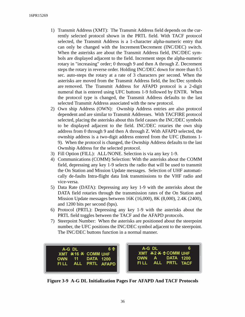
16PR15269
1) Transmit Address (XMT): The Transmit Address field depends on the cur-rently selected protocol shown in the PRTL field. With TACF protocolselected, the Transmit Address is a 1-character alpha-numeric entry thatcan only be changed with the Increment/Decrement (INC/DEC) switch.When the asterisks are about the Transmit Address field, INC/DEC sym-bols are displayed adjacent to the field. Increment steps the alpha-numericrotary in "increasing" order; 0 through 9 and then A through Z. Decrementsteps the rotary in reverse order. Holding INC/DEC down for more than 0.5sec. auto-steps the rotary at a rate of 3 characters per second. When theasterisks are moved from the Transmit Address field, the Inc/Dec symbolsare removed. The Transmit Address for AFAPD protocol is a 2-digitnumeral that is entered using UFC buttons 1-9 followed by ENTR. Whenthe protocol type is changed, the Transmit Address defaults to the lastselected Transmit Address associated with the new protocol.
2) Own ship Address (OWN): Ownship Address entries are also protocoldependent and are similar to Transmit Addresses. With TACFIRE protocolselected, placing the asterisks about this field causes the INC/DEC symbolsto be displayed adjacent to the field. INC/DEC rotaries the own shipaddress from 0 through 9 and then A through Z. With AFAPD selected, theownship address is a two-digit address entered from the UFC (Buttons 1-9). When the protocol is changed, the Ownship Address defaults to the lastOwnship Address for the selected protocol.
3) Fill Option (FILL): ALL/NONE. Selection is via any key 1-9.4) Communications (COMM) Selection: With the asterisks about the COMM
field, depressing any key 1-9 selects the radio that will be used to transmitthe On Station and Mission Update messages. Selection of UHF automati-cally de-faults Intra-flight data link transmissions to the VHF radio andvice-versa.
5) Data Rate (DATA): Depressing any key 1-9 with the asterisks about theDATA field rotaries through the transmission rates of the On Station andMission Update messages between 16K (16,000), 8K (8,000), 2.4K (2400),and 1200 bits per second (bps).
6) Protocol (PRTL): Depressing any key 1-9 with the asterisks about thePRTL field toggles between the TACF and the AFAPD protocols.
7) Steerpoint Number: When the asterisks are positioned about the steerpointnumber, the UFC positions the INC/DEC symbol adjacent to the steerpoint.The INC/DEC buttons function in a normal manner.
Figure 3-9 A-G DL Initialization Pages For AFAPD And TACF Protocols
A-G DL 6
ALLFI LL
OWN
XMT
PRTL
COMMXX
DATA
AFAPD
1200
UHF16
11
A-G DL 6
ALLFI LL
OWN
XMT
PRTL
COMMXX
DATA
TACF
1200
UHF2
A
36

16PR15269
NOTE: In order to receive and transmit messages to one another, the par-
ticipants must have the same data rate and protocol selected.
Mission Update Message (Receive Only):When a CAS message is received, the mnemonic "CAS## DATA" is displayed in the
center of the HUD and a VMU message "Data" is broadcast. The HUD mnemonic remains dis-played until either Warn Reset is depressed and released or the CAS page is selected. "##" indi-cates the steerpoint number where the CAS message is stored.
CAS messages are stored in steerpoints 71-80, which are shared locations with Penguinand Mark-point data link messages. Received messages (CAS, Penguin, and/or Mark-point) aresequentially stored in steerpoints 71-80. When the steerpoint range is full, the system wraps backto steerpoint 71 and overwrites the old data stored there. Stored CAS messages are retainedthrough MMC power cycles when airborne and are cleared at the start of a new mission (missionreset).
CAS messages received in AFAPD protocol are stored in an Initial Point (IP) and a Tar-get (TGT) location for steerpoints 71-80. The received CAS IP and TGT are displayed on the HSDprovided they are within the HSD FOV. The IP is displayed as a square and the TGT as a triangle(Figure 3-10). Hands-on selection of CAS messages (displaying the CAS page on the DED) andselecting the CAS IP or CAS TGT as the current steerpoint, is available only when the SOI is onthe HSD. For example:
1) TMS Forward (Designate): Designating on a CAS IP or TGT symbol onthe HSD, places a square around ("boxes") the symbol and establishes thepoint as the current Data Link Target Of Interest (DL TOI). Designating ona boxed CAS IP or TGT converts the DL TOI to the currently selectedsteerpoint and fills-in the symbol (square or triangle) on the HSD.
2) TMS Right (RT): Selects the last received CAS message and places asquare around ("boxes") the CAS IP or CAS TGT if no IP is available. Asubsequent TMS RT steps the box to the CAS TGT (if a CAS IP wasboxed) or next CAS STPT in sequence (STPTs 71-80) if a CAS TGT wasboxed. A TMS RT from steerpoint 80 will cause the system to wrap back tosteerpoint 71 in search of the next available CAS steerpoint.
3) TMS Left (LT): Displays the CAS DED page; or, if the CAS DED page isbeing displayed, sequences to the next CAS DED page in the rotary (STPTs71-80).
4) TMS Aft: Drops a boxed CAS IP or CAS TGT.
NOTE:When an AFAPD CAS message is received, full IP and TGT data are available via the three CAS pages shown in Figure 3-12. TACFIRE CAS messages only provide target data on a single CAS page (Figure 3-13). Latitude, longitude, elevation and TOS can be updated on the CAS Destina-
tion pages (Figure 3-14) and CAS Steerpoint pages.
37
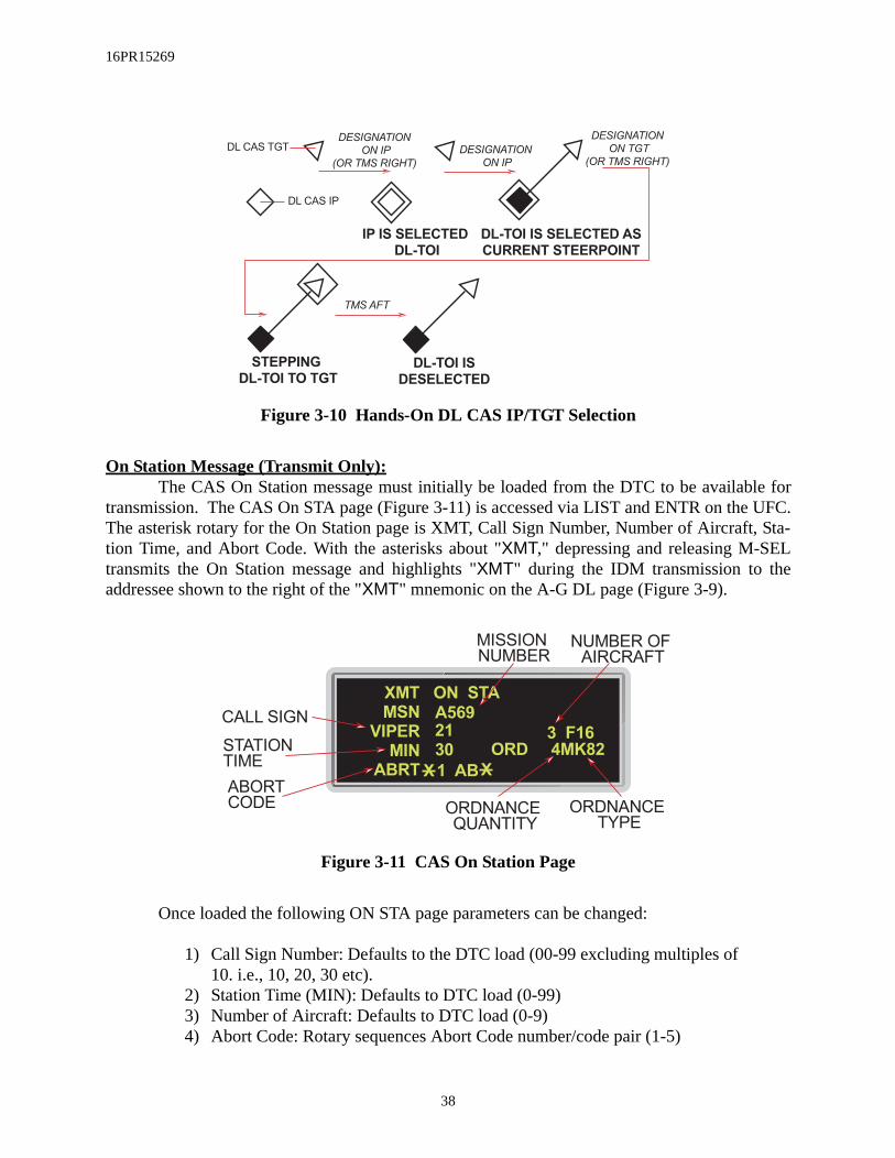
16PR15269
Figure 3-10 Hands-On DL CAS IP/TGT Selection
On Station Message (Transmit Only):The CAS On Station message must initially be loaded from the DTC to be available for
transmission. The CAS On STA page (Figure 3-11) is accessed via LIST and ENTR on the UFC.The asterisk rotary for the On Station page is XMT, Call Sign Number, Number of Aircraft, Sta-tion Time, and Abort Code. With the asterisks about "XMT," depressing and releasing M-SELtransmits the On Station message and highlights "XMT" during the IDM transmission to theaddressee shown to the right of the "XMT" mnemonic on the A-G DL page (Figure 3-9).
Figure 3-11 CAS On Station Page
Once loaded the following ON STA page parameters can be changed:
1) Call Sign Number: Defaults to the DTC load (00-99 excluding multiples of10. i.e., 10, 20, 30 etc).
2) Station Time (MIN): Defaults to DTC load (0-99)3) Number of Aircraft: Defaults to DTC load (0-9)4) Abort Code: Rotary sequences Abort Code number/code pair (1-5)
DL CAS TGT
DL CAS IP
IP IS SELECTED
DL-TOI
DL-TOI IS SELECTED AS
CURRENT STEERPOINT
STEPPING
DL-TOI TO TGT
DL-TOI IS
DESELECTED
DESIGNATION
ON IP
(OR TMS RIGHT)
DESIGNATION
ON IP
TMS AFT
DESIGNATION
ON TGT
(OR TMS RIGHT)
XMT ON STA
30MIN
VIPER
MSN
ABRT
A569
X X
3 F16
1 AB
ORD 4MK82
21CALL SIGN
ABORTCODE
STATIONTIME
MISSIONNUMBER
NUMBER OFAIRCRAFT
ORDNANCETYPE
ORDNANCEQUANTITY
38

16PR15269
When an AFAPD CAS message is received, full IP and TGT data are available via threeDED CAS pages (Figure 3-12). TACFIRE CAS messages only provide target data on a singleDED CAS page (Figure 3-13). Latitude, longitude, elevation and TOS can be updated on theCAS Destination page (Figure 3-14) and CAS Steerpoint page.
Figure 3-12 AFAPD CAS Mission Update Pages
Figure 3-13 TACFIRE CAS Mission Update Page
Figure 3-14 CAS Steerpoint Destination Page
CAS I P 79
LEFTOFST
DESC
FROM
IP-TGT P1>
HOG 16
RR BRIDGE
CAS TGT 80
2 , 500FTELEV
DESC
FROM
LASER /1234MARK P2>
HOG 16
ARTILLERY
CAS TGT 80
P3>
RMKS
FRND
MOVING SW SLOW
SW 3 . 2NM
TARGET IN OPEN
018 /15 . 6NMo
SEQRTN
SEQRTN
CAS TGT 80
2 , 500FTELEV
DESC
FROM
LASER /1234MARK
HOG 16
ARTILLERY
CAS
0 FTELEV
LNG
LAT
TOS
N
XX
58 29 . 211'
00 : 00 : 00
9 54 . 219'
79
W
o
o
39

16PR15269
IDM-Allow A/A Target Assignments In Continuous Mode (RDP-875)The Improved Data Modem (IDM) has been modified such that the Assign (ASGN) and
Continuous (CONT) modes allow data link assignments of the current FCR Target Of Interest(TOI) to another team member via OSB #7 through #10 on the FCR format. The selected OSBlabel highlights and changes to "XMT". The assignment message is broadcast to the intraflightteam and consists of position, velocity, and heading of the assigned target. DL unknown and teammember target symbols are displayed for 8 seconds on the FCR and HSD formats. No changewas made to the baseline method of assigning FCR targets via the IDM. An intraflight round canbe requested in the ASGN mode for display on the A-A FCR and/or HSD formats.
Highlight CONT Mnemonic To Indicate Active CONT Operation (RDP-1239)The CONT mnemonic is highlighted on the MFD (Figure 3-15) when a CONT round is
commanded and remains highlighted to indicate your aircraft is the CONT round controller.When a A-A request is received from another aircraft (transition out as CONT controller), orwhen a transition to RF Quiet/Silent (detected by the MMC), the CONT highlight is removed.
Figure 3-15 Continuous Mode Active/Silent
IDM-Expand Net Size To 8 Members (RDP-872)The DED Intraflight page (Figure 3-16) has been modified to allow entry/setup for 8
team member addresses. The HSD format provides the display of up to 8 DL friendly positionsand Identifications (ID). IDs 1 to 4 represent your 4-ship team package with the ID (1-4) abovethe aircraft symbol. A-A data link assignments can only be made among this four ship package.The second four ship package (Team IDs 5-8) is displayed with their team address (two digitnumber) above the symbol.
Figure 3-16 DED Intraflight Initialization Page
SYMSYM
CNTL
CONT
OVRD OVRD CNTL
CONT
NORM
R
F
Q
U
I
E
TSILENT
NORM
R
F
Q
U
I
E
TSILENT
XMT 4
LAST
OWN
DATA
COMM
I NTRAFLIGHT
#4
#3
#2
#1
X30
34
33
32
31
#8
#7
#6
#5
13
12
11
#7
3 1
1 6K
VHF
X XXMT 6
LAST
OWN
DATA
COMM
I NTRAFLIGHT
#4
#3
#2
#1
X10
13
12
11
#8
#7
#6
#5
34
33
32
31
#7
1 1
1 6K
VHF
X X
TEAM PACKAGE DED MEMBER TEAM DED
MEMBER ID
MEMBER ADDRESS
INTRAFLIGHT
RADIO
DATA RATE
OWNSHIP
ADDRESS
TEAM SIZE
TEAM IDTEAM ADDRESS
40

16PR15269
ber’sassign,
s dis-
and
pilot threatthreats. steady
than CAS
. TMS-
The MFDs display up to 8 DL unknown symbols: the bugged target of the four teammembers and the team members assignments. The MFDs display 1 through 4 centered above thesymbols for team members (1-4). The Team Address (##) is displayed above the four DLFriendly Team members (5-8) (Figure 3-17). Bugged targets for team members 5 to 8 are not dis-played. Data link targets outside of the FOV arrows (see SECTION 1 - RDP-884) are only dis-played for the 4-ship team (3-ship in Figure 3-16).
Round time for eight members was expanded to approximately 12-14 seconds followedby a variable delay (DTC loadable 1.4 to 5.5 sec. in continuous mode). If the team size is lessthen eight, the round time is adjusted according to the number of team members. The displaytimer was reduced to 8 seconds for DL Team Member, DL Friendly, and DL Team memUnknown TOI symbols. These symbols no longer flash the last five seconds in any mode (continuous, or demand).
When a Friendly Team Member (5-8) passes his A-G cursor position, his symbol iplayed with his Team Address (##) above the symbol (Figure 3-17).
Figure 3-17 MFD Data Link Friendly And Unknown Symbols
IDM SEAD Changes (RDP-1015)M2 modified the HSD controls and displays to improve the ability to recognize
manipulate data link targets received by the system. The enhancements include:
1) More unique SEAD threat symbols2) Mipple the threat symbol and “DL” until the data link threat is boxed or
warn reset is depressed3) Hands-on designating the most recently received threat on the HSD when
the DL TOI already exists
When a SEAD DL threat is received, the threat symbol and “DL” mipple to alert the to its position on the HSD until boxed or Warn Reset is depressed. Designating over aboxes the threat and stops the mipple. Depressing Warn Reset stops the mipple of all After the threat has been boxed or WARN RESET is depressed, the threat symbol remainswith a slash “/” across the symbol. (See Figure 4-28.)
With the SOI on the HSD and a SEAD symbol boxed, a TMS-right command for lessone second steps the box among the displayed data link SEAD symbols. Likewise, if asymbol is boxed, a TMS-right for less than one second steps the box among CAS symbols
3
20
2
15
23
20
DL TEAM
MEMBER
DL
FRIENDLY
DL TEAM
MEMBER'S
UNKNOWN TOI
FRIENDLY
ADDRESS
TEAM
ID
41

16PR15269
n theessing
ion pri-mined
a
right-and-hold for greater then one second auto-designates the latest DL message. If no data linktargets have been received, the TMS-right-and-hold command is ignored. If the auto-designatedata link target is a DL SEAD threat and its position is outside the current HSD FOV, the rangescale will increase up to a maximum of 120 nautical miles depressed or 80 nautical miles cen-tered, as required to display the threat. At maximum range, if the threat is still beyond the HSDFOV, the threat will be displayed using an outside-FOV symbol (filled-in triangle) along the outerrange ring at the correct azimuth pointing toward the target.
If the DED DL SEAD or CAS page is displayed for a DL target and a new DL target isboxed, the DED page will update with the new DL target data. For additional information con-cerning DL SEAD operations, see SECTION 4-HARM DL Mode.
ASSIGN Message In HUD (RDP-1242)“ASSIGN” is displayed in the HUD for 8 seconds (the same as the display time o
assignment unknown track on the MFD) upon receipt on an ASSIGN message. DeprWARN RESET removes the “ASSIGN” cue from the HUD.
Ownship Symbol Occlusion By Team Member Data Link Symbols On HSD (RDP-1241)
The ownship symbol and the team member data link symbols have the same occlusority level on the HSD. This allows the relative positions of team members to be deterwhen the team members and the ownship symbols overlap.
IDM Messages Zeroize (RDP-983)
M2 provides the capability to delete DL SEAD and CAS (IP and TGT) messages viahands-on controls. Designating the DL SEAD target text on the HSD places a box about the DLtarget text. With the cursor over the box and TMS aft for greater than one second deletes the DLSEAD message from the system and removes the target text from the HSD. The same proceduredeletes a CAS message from the system by designating either the IP or target symbol. Placingthe cursor over the box and TMS aft for greater than one second deletes the DL CAS messagefrom the system for both the IP and target and removes the IP and target symbols from the HSD.TACFIRE CAS messages only contain target information. TMS aft for less than one secondremoves the box from the target. When a data link target is deleted, the lat/long/elev of the steer-point is zeroed, and the TOS is set to -0. In addition, stored SEAD or CAS information is deleted.
Flexible Data Link Steerpoints (71-80) (RDP-873)M2 modified the steerpoint data link mechanization to make data link steerpoint entry
more flexible. Data link steerpoints are stored in steerpoint positions 71 to 80. The avionics sys-tem does not use weapon load information to determine whether or not to accept a data link steer-point.
Steerpoint 30 has been grouped with steerpoints 26-29 for storing ownship Mark points.The HSD displays the location of each DL markpoint (STPT 71-80) as a large “X”, while ownshipmarkpoints (STPT 26-30) are displayed as a small “x”. data link markpoints are cleared whenMission Reset occurs.
42

16PR15269
ACM-One Switch Action To NO-RAD (RDP-626)The Target Management Switch (TMS) aft (RTS) function was changed as follows:
1) Any ACM radiating submode, TMS aft enters ACM 30x20 NO-RAD.2) From 30x20 NO-RAD, TMS aft enters ACM 10x60 radiating submode
TMS aft is the only switch action that commands a break lock from an ACM track mode.When ACM is entered and a submode is requested, the FCR will radiate regardless of the
position of the RF switch. Moving the RF switch from NORM to QUIET or SILENT while inACM has no effect on the radiate state. While the RF switch is in Quiet or Silent, the FCR willcontinue to radiate until you exit ACM without a bugged target.
Bug Stepping To Track Files Limited To Selected Range (RDP-1158)FCR bugged target stepping is limited to track files displayed on the current FCR range
scale and range is no longer bumped up to track files existing beyond the selected range.
SAM Multi-Track (SMT) Mode Transfer Remechanization (RDP-1165)The “Last Left” mode is maintained for the following FCR CRM mode transitions:
• SMT Å RWS (TTS/SAM/STT) Å SMT• TWS Å RWS (TTS/SAM/STT) Å TWS
43

16PR15269
earingin thearing,
Breaklock Reacquisition Symbology In SAM (RDP-1243)When the FCR is in SAM, a reacquisition symbol (Figure 3-18) is displayed at the last ele-
vation of the lost bugged target on the FCR format.NOTE:
This feature should be considered inop since it is not currently supported by the APG-66V radar.
Figure 3-18 FCR CRM/RWS SAM Mode
Cursor Digital Search Altitude Information (RDP-351)The default color for the FCR cursor minimum search altitude display for real negative
values is red (Figure 3-18), however, the color is DTC loadable.
HUD Ownship Bull’s-Eye (RDP-1229)When bull’s-eye bearing and range is mode selected and in an A-A FCR mode, the b
and range from bull’s-eye to ownship is displayed below the mode display (Figure 3-19) HUD (lower left corner). The bearing and range information is an 8 character field (3 for be2 blank spaces, followed by 3 for range) for easy interpretation.
GAIN SYM
BRT CON
SWAP DCLT
20
FCR
CRM CNTLOVRD
CONT
A3
RDYSMS
NORMRWS
2B
M3
08
-02
150 28
06
28
150
REACQUISITIONCARET
44

16PR15269
range.
rmat
dingother
Figure 3-19 HUD Bull’s-Eye Bearing And Range
HUD window #15 is a shared field, therefore, when conditions are met for GND PROX,TRP FUEL, or FUEL, the HUD displays the appropriate mnemonic. Also if the Visual Identifica-tion (VID) mode is selected, the target altitude has priority over the bull’s-eye bearing and The message priority for this field is:
1) GND PROX2) TRP FUEL3) FUEL4) VID TOI (target altitude)5) Ownship Bearing and Range from Bull’s-eye
Update Bull’s-Eye Position In Expand (RDP-1415)The Bull’s-eye symbol is displayed in it’s expanded position on the FCR EXPAND fo
when it is in the FCR expanded FOV.
LANTIRN Targeting Pod Interface (RDP-864)A more complete description of the LANTIRN Targeting Pod (TGP) features, inclu
control and display options is contained in SECTION 4 - Air-To-Ground. If a targeting pod than LANTIRN is used, subtle operational differences may exist.
The LANTIRN TGP A-A features include:
1) Tracking A-A Targets2) A-A TGP LOS Indicator In The HUD
06 08070
6,000450
55
5 5
50
40
06,5
05,5
1.0
C
0.324.1NAV
R 2,500
AL 200
F002. 6
018>03103224
10 10180 125
WINDOW #15PRIORITY
TRP FUELFUELVID TOIBRG/RNG
45

16PR15269
d the
andent of
is an not
dia-target
target-
3) Laser Ranging On A-A Targets4) Slaving The FCR LOS To The TGP LOS5) Slaving The AIM-9 Missile To The TGP LOS6) Perform Sensor/AIM-9 LOS Correlation
TGP Tracking A-A Target:In A-A, if an A-A bugged target is present, the TGP LOS is slaved to the FCR LOS, and if
a bugged target is not present, the TGP LOS is commanded to boresight (0-degrees azimuth andminus 3-degrees elevation). The TGP may be commanded to track the FCR A-A target by mov-ing the SOI to the TGP and activating a TMS-forward command. Without an FCR track, the pilotmay maneuver the aircraft to place the target within the center of the TGP’s field of view andTMS forward to command tracking. Once the TGP is tracking, it is independent of the FCR.
A-A TGP LOS Indicator On The HUD:When the TGP is tracking an A-A target in the HUD FOV, a dotted Target Designator
(TD) box is placed at the TGP LOS on the HUD. If the TGP is tracking a target outside the HUDFOV a dotted Target Locator Line (TLL) extends from the bore cross in the direction of the TGPLOS. The target angle in degrees is positioned along the TGP TLL at 65-mr from the bore cross.The A-A FCR TLL target angle is positioned 45-mr from the bore cross allowing both targetangles to be read when the TLLs are close together. The TGP TD box and TLL are displayedindependent of the FCR TD box and TLL.
Laser Ranging On A-A Targets:When the A-A TGP is in Point Track with the Master Arm switch in ARM and the laser
in ARM, depressing the trigger to the first detent fires the TGP laser. The reported laser range isdisplayed on the TGP page, if no range is reported “XXX” is displayed. Both the FCR anTGP ranges are displayed at the same time on the HUD.
Slaving The FCR LOS To The TGP LOS:When the TGP is tracking an A-A target with the FCR in Air Combat Mode (ACM)
TMS right is activated, the FCR commands ACM Boresight along the TGP LOS independSOI.
Slaving The AIM-9 Missile To The TGP LOS:When the TGP is tracking an A-A target and is the SOI, if the selected weapon
AIM-9 in Slave, that AIM-9 will be slaved to the TGP LOS. If the TGP is the SOI but istracking a target, the caged AIM-9 is slaved to the Armament Datum Line (ADL).
When the TGP is the SOI, the Dynamic Launch Zone (DLZ) is blanked, the missilemond does not flash to indicate a good shot, and the AIM-9 missile reticle is void of the aspect symbol and the range tics/gap.
Perform Sensor/AIM-9 LOS Correlation:When the sensor (TGP or FCR) LOS and the AIM-9 are correlated on the same
(within 1.5 degrees of each other) outside the HUD FOV, a “C” is displayed to the left of the target angle for the respective sensor.
46

16PR15269
Attitude Awareness In DGFT (RDP-820)Attitude awareness in DGFT is provided on the HUD through the Attitude Awareness Arc
(AAA) and the Ghost Horizon Line (GHL). The Attitude Awareness Arc provides a global pic-ture of pitch and roll attitude in the form of an arc. Roll is provided by the angle of an imaginaryline through the ends of the arc in relation to the HUD. During wings level flight the arc gap istoward the top of the HUD, while during inverted flight, the arc gap is toward the bottom of theHUD (Figure 3-20) and indicates the upright attitude. The arc represents the ground.
Figure 3-20 Nose-down Inverted Attitude Awareness Arc
The attitude arc is not adjusted for winds or aircraft yaw and is roll stabilized about thecenter of the HUD Total Field Of View (TFOV). The curvature of the arc represents the directionof the ground, and an imaginary line connecting the ends of the arc represents a line parallel to thehorizon. In level flight the arc forms a half circle. As the aircraft increases nose-up pitch, the arclength decreases (Figure 3-21). As the aircraft noses over below the horizon, the arc lengthincreases (Figure 3-22). The arc is at its smallest length at 87-degrees nose-up and is at its longestlength at 87-degrees nose-down.
450
0204
2.5
C
0.894.12 SRM F031. 2
012>02001:36
ARM
22,500175
AA 4L
47

16PR15269
Figure 3-21 Left Climbing Bank Attitude Awareness Arc
Figure 3-22 Nose-down Wings Level Attitude Awareness Arc
The GHL appears when the aircraft exceeds +/-10 degrees of pitch to enhances attitudeawareness in conjunction with the Attitude Awareness Arc.
430
0204
2.5
C
0.874.12 SRM F001. 2
012>02001:39
ARM
22,650150
AA 4L
480
0204
2.5
C
0.924.12 SRM F031. 2
012>02001:26
ARM
22,340180
AA 4L
48

16PR15269
Target Altitude In HUD (RDP-1361)The target altitude replaces the ALOW setting on the HUD when the FCR is in an A-A
mode and data concerning the bugged target and system altitude are valid. The ALOW altitudesetting is moved above the altitude scale (Figure 3-23).
Figure 3-23 Target Altitude Display In MLU HUD
Heads Up Indication Of Imminent Radar Break Track (RDP-1049)This candidate uses the existing M1 FCR Coast mechanization to provide a head-up indi-
cation that the FCR is about to break track. A dashed TD box appears when an imminent breaklock condition occurs and the FCR TOI is in the HUD field of view. If the TOI is outside theHUD field of view and a imminent break lock condition occurs, a dashed Target Locator Line(TLL) appears in the HUD.
For clarification, the original Coast mechanization remains unchanged. A dashed TDbox appears when a coast situation occurs for the FCR TOI located within the HUD field of view,and "COAS" appears in the target closure rate portion of the Missile Launch Envelope (MLE). Ifthe TOI is outside the HUD field of view and a coast situation occurs, a dashed TLL is displayed,and "COAS" appears in the target closure rate portion of the MLE.
EEGS Improvements: Flexible MRGS (RDP-796)In the previous HUD OFP, the Multiple Reference Gunsight (MRGS) lines were drawn
assuming a target fuselage length of 60 feet. Consequently, the in-range cue that is provided bycomparing the apparent target fuselage length with the MRGS line length was only accurateagainst 60-foot long targets. Therefore, to improve the accuracy of the MRGS in-range indication,
450
R 19,800
2.5
C
1.024.12 MRM
AL 200
115>30014:43
ARM
22,500
80012M
F016.0TA025
TARGETALTITUDE
ALTITUDE LOWSETTING
49

16PR15269
the lines are now drawn assuming a target length that is 1.5 times the entered target wing span.Target wing span can be entered via the DED Manual page (Figure 3-24) or the DTE load.
Figure 3-24 DED Manual Page
EEGS Improvements: Clamp MPLs (RDP-798)The extended range of the PGU-28 round also results in greatly extended Maneuver
Potential Lines (MPLs). So, to prevent confusion with the horizon line, the total length of bothMPLs plus the T-gap has been limited to a maximum of 100 mils.
Remove Max Range Dot When In Range (RDP-800)To reduce the possibility of the pilot confusing the max range dot for the Level V pipper,
the new HUD OFP removes the max in-range dot (Figure 3-25) when the target is 1,000 feet ormore inside the maximum range. The max in-range dot reappears when the target has an openingvelocity and exceeds the maximum range.
Figure 3-25 Gun In-Range Indications
12000FT
44FT
MAN 12
TOF
RNG
11. 3SEC
MBAL
WSPAN
MAX GUN RANGE (MGR) MGR - 1000 FT MAX GUN RANGE DOT
OWNSHIPHUD LEVEL V
PIPPER
TARGETS AT RANGE
13,000 FT
8,000 FT
50

16PR15269
Continuous FEDS (RDP-910)M2 adds two pair of Firing Evaluation Display System (FEDS) dots for a total of seven
pairs so that with continuous trigger squeeze the FEDS should travel down the EEGS funnel for aminimum of 1.4 seconds. Upon trigger release, the FEDS continue down the EEGS funnel for amaximum time of TFMAX1. TFMAX1 is computed by the EEGS algorithm. With a new triggersqueeze, the MMC removes the oldest pair of FEDS dots as they reach TFMAX1 and displays anew pair at the top of the funnel (Figure 3-26).
Figure 3-26 EEGS FEDS At Trigger Squeeze And Release
No-Lock Training Mode (RDP-591)M2 provides the capability to select EEGS Level 2 training while maintaining a radar
lock. The level 2 No Lock Training mode is selected via OSB #9 (TNG ON) on the Stores Man-agement Set (SMS) Base page (Figure 3-27).
Figure 3-27 SMS Base Page
1.4 seconds TOF1.4 seconds TOF 1.4 seconds TOF
TFmax1TFmax1
ON - TRIGGER OFF - TRIGGERON - TRIGGER
AGAIN
GAIN SYM
BRT CON
SWAP SMS HSD S-J
GUN
RDY
RDY 51GUNSCOR
ON
I NVEEGS
TNG
ON
W
EEGS
NO-LOCK
TRAINING
MODE
51

16PR15269
With No Lock Training selected, the FCR radar is allowed to track the target so that theBullets At Target Range (BATR) symbol can be computed and displayed. The BATR scoringindication is provided at trigger squeeze. The EEGS display is restricted from transitioningbeyond EEGS Level II (no radar lock) as it normally would when the FCR is tracking a target.The EEGS No Lock Training mode consists of Level II symbology with the exceptions thatBATR is displayed in place of FEDS and target slant range and target closure range are displayed(Figure 3-28).
Figure 3-28 EEGS Level II vs. EEGS Level II No-Lock Training Mode
Remech Hands-On Missile Select (RDP-1070)Depress and Release (D&R) of the Missile Step switch on the sidestick controller pro-
vides hands-on selection of a stores station. When in an A-A master mode, D&R of the MissileStep switch for <0.5 seconds selects the next stores station in the rotary (3, 7, 2, 8, 1, 9) with theselected weapon type. The selected station is identified on the SMS Base page by inverse video.Hands-off changes remain the same. Station selection is remembered through MMC powercycles.
When in an A-A master mode and RECCE is not the SOI, depress and hold the missilestep switch ≥ 0.5 seconds to select the next missile type in the A-A weapon selection rotary. Theavionics system automatically selects the next missile type in the A-A rotary and displays thenewly selected weapon mnemonic adjacent to OSB #7 on the SMS Base page. The missile type(SRM, MRM) will also change on the HUD if the new missile is a different type.
There are no changes to weapon selection in the A-G master mode.
AIM-9L/M Bore/Slave Operations (RDP-519)Once an AIM-9L/M is uncaged and tracking a target, the avionics system no longer
automatically cages the missile when changing the Line-Of-Sight (LOS). Depressing cursor-Z orthe BORE/SLAVE OSB #19 on the SMS page has no effect on the caging or uncaging of the mis-sile, however, the BORE/SLAVE label is changed. Once the missile is recaged via the uncage
450
4.5
C
6.2
SIM
22,500
NO RAD
450
4.5
C
6.2
SIM
22,500
BATR
0057F 070
FUNNEL
FEDS
MRGS
AA 15L
52

16PR15269
B #19P, the
es the
ing arackeds mis-
k. Thee, ands sys-ed targetpleted,llow
switch or the missile station is changed, the missile is commanded to the LOS displayed on theSMS page.
AIM-9 Auto Acquisition Mechanization (RDP-447)M2 provides a selectable AUTO Acquisition mode programmable via the DTE. It pro-
vides automatic uncaging of the AIM-9 seeker head when the target is within AIM-9 range. Italso provides automatic verification that the target LOS is within the selected AIM-9 LOS. If thetarget is outside the AIM-9 LOS, it automatically slaves the AIM-9 to the target LOS. An AUTOAcquisition mode message “SHOOT” is displayed on the HUD.
The AUTO option is only allowed when the TGP is not the SOI. AUTO is selected onthe SMS Base page (Figure 3-29) when in the AAM mode. AUTO is removed from the OSrotary when the TGP is the SOI. When AUTO is selected and the SOI is moved to the TGmissile LOS is automatically changed to SLAVE. Moving the SOI back to the FCR re-enablAUTO mode. SLAVE and Boresight (BORE) modes are retained through SOI transitions.
Figure 3-29 SMS Base Page
The avionics system provides 3 verification checks in AUTO when the FCR is tracktarget and the missile is correctly slaved to the target. The first check verifies range of the ttarget is within missile range. When in range, the avionics system automatically commandsile self-track (uncage). The second check verifies the missile is commanded to self-tracthird check verifies the tracked target LOS is within +/- 27 degrees of the missile centerlinthe missile’s LOS is within +/- 1.5 degrees of the tracked target LOS. Otherwise the avionictem commands missile to cage, and then commands the missile seeker head to the trackLOS, and then starts the first check again. When all checks are successfully com“SHOOT” is flashed on the HUD (Figure 3-30). “Shoot” is displayed as long as conditions a
GAIN SYM
BRT CON
SWAP SMS HSD S-J
AAM
RDY
RDY 4 A-9LMAUTO
I NVSPOT
W
COOLBP
1 2 M M 8 98
53

16PR15269
sameand
as
on sta-apon
nged
the shot to occur and no other higher priority messages exist. “SHOOT” is displayed in thewindow as “FUEL” with “FUEL” having priority. The avionics system continues checks removes “SHOOT” if one of the checks fail.
Figure 3-30 HUD Shoot Indication
Weapon Selection Not Affected By Inventory Manipulations (RDP-1503)In M1 when the SMS inventory was changed, the AIM-9L/M cooling option w
replaced with WARM regardless of whether the inventory affected AIM-9L/M missiles.In M2 when changing inventory not related to AIM-9L/M, the WARM/COOL opti
remains in its current state. When making an AIM-9L/M related change, the WARM/COOLtus is set to WARM. Inventory changes at different stations do not affect the following wepower settings:
1) AMRAAM Telemetry2) AGM-65 Power3) HARM Weapon Power
AMRAAM DLZ Changes (RDP-975); AMRAAM LOFT Cue (RDP-756)The physical appearance and the terminology defining the AMRAAM DLZ has cha
significantly in M2 (Figure 3-31).
450
50
0204
2.5
C
0.324.15 SRM F001. 2
012>02000: 58
SHOOT
ARM
22,500800
54

16PR15269
1) Active Seeker Cue Deleted: The active seeker range cue (small circle) wasdeleted. Pilots no longer require an active seeker range cue.
2) Range Optimum (ROPT) Cue: A small circle (deleted active seeker rangecue) depicts the maximum AMRAAM launch range assuming optimum-steering and high quality termination criteria.
3) RMAX1 Re-designated: The RMAX1 part of the DLZ was changed to reflectRange Probability of Intercept (RPI). RPI is the maximum range shot withprobable intercept given current steering, aircraft pitch or azimuth changesare not required.
4) RMAX2 Re-designated: The RMAX2 part of the DLZ was changed to RangeTurn and Run (RTR). RTR represents the maximum range shot assumingthe target performs a “Turn and Run” maneuver at launch.
5) RMIN1 and RMIN2 Deleted: The RMIN1 and RMIN2 cues were replaced witha single RMIN cue on the AMRAAM DLZ. RMIN is positioned based onRMIN1 calculations.
6) Range Aerodynamic (RAERO) Cue: The RAERO cue (small triangle) wasadded to the AMRAAM DLZ on the HUD and MFD. The RAERO cue rep-resents the maximum kinematic range of the AMRAAM and is the longest-range shot that a pilot can take a shot and have a chance of hitting the tar-get. RAERO assumes that the target will not maneuver; that the missile isperfect; and optimum loft conditions are achieved.
Figure 3-31 AMRAAM Dynamic Launch Zone Components
910
40
Target Rng Cue
Raero: Max Missile Kinematic Range.
Loft Angle/ Solution Cue: The Required Pitch To Achieve RPI.(Displayed In 5 Degree Increments.)
Radar Rng Scale Value
Zero Rng Tic Mark
Dynamic Rng Scale Tic Mark
ROPT:
RPI:
RTR:
RMIN:
Max Launch Range. Assumes Optimum Aircraft SteeringAnd High Quality Termination Criteria.
Represents A Max Range Launch With Intercept Probable Given Current Steering.
Represents Max Range Shot Assuming Target Performs A Turn And Run Maneuver At Pickle.
Represents Minimum AMRAAM Launch Range.Does Not Consider Post Shot Maneuvering
91040
16MM/F Pole Pre-Launch Rng
M-POLE:
F-POLE:
Range From Ownship To Target WhenAMRAAM Goes To Active
Range From Ownship To Target At AMRAAM Impact
UNEXPANDED DLZ
EXPANDED DLZ
Target Closure
AMRAAM DYNAMIC LAUNCH ZONE (DLZ) COMPONENTS
55
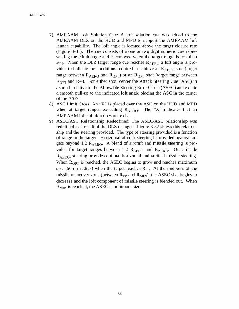
16PR15269
7) AMRAAM Loft Solution Cue: A loft solution cue was added to theAMRAAM DLZ on the HUD and MFD to support the AMRAAM loftlaunch capability. The loft angle is located above the target closure rate(Figure 3-31). The cue consists of a one or two digit numeric cue repre-senting the climb angle and is removed when the target range is less thanRPI. When the DLZ target range cue reaches RAERO a loft angle is pro-vided to indicate the conditions required to achieve an RAERO shot (targetrange between RAERO and ROPT) or an ROPT shot (target range betweenROPT and RPI). For either shot, center the Attack Steering Cue (ASC) inazimuth relative to the Allowable Steering Error Circle (ASEC) and excutea smooth pull-up to the indicated loft angle placing the ASC in the centerof the ASEC.
8) ASC Limit Cross: An “X” is placed over the ASC on the HUD and MFDwhen at target ranges exceeding RAERO. The “X” indicates that anAMRAAM loft solution does not exist.
9) ASEC/ASC Relationship Rededfined: The ASEC/ASC relationship wasredefined as a result of the DLZ changes. Figure 3-32 shows this relation-ship and the steering provided. The type of steering provided is a functionof range to the target. Horizontal aircraft steering is provided against tar-gets beyond 1.2 RAERO. A blend of aircraft and missile steering is pro-vided for target ranges between 1.2 RAERO and RAERO. Once insideRAERO, steering provides optimal horizontal and vertical missile steering.When ROPT is reached, the ASEC begins to grow and reaches maximumsize (56-mr radius) when the target reaches RPI. At the midpoint of themissile maneuver zone (between RTR and RMIN), the ASEC size begins todecrease and the loft component of missile steering is blended out. WhenRMIN is reached, the ASEC is minimum size.
56

16PR15269
Figure 3-32 ASEC/ASC Relationship
AMRAAM DLZ Transitions (Figure 3-33):
1) Unexpanded AMRAAM DLZ Scale: When the current target range isgreater than 125% of RAERO, the AMRAAM DLZ is displayed on theHUD and MFD in an unexpanded configuration. On the HUD the upperand lower range scale tics are displayed at their static locations and theradar range scale digital readout is displayed above the upper range scaletic. The remaining AMRAAM DLZ parameters (target range caret,RAERO, ROPT, RPI, RTR, and RMIN) are positioned relative to the upperrange scale tic which represents the current radar range scale value and thelower tic that represents zero range.The upper and lower boundaries of the unexpanded MFD DLZ areunmarked points located 75% (upper boundary) and 25% (lower boundary)above the bottom of the MFD display area. The upper boundary representsthe currently selected radar range scale value and the lower boundary rep-resents zero range. The remaining AMRAAM DLZ parameters are posi-tioned relative to the upper boundary.
R
R
R
R
R
AERO
OPT
PI
TR
MIN
ASECSIZE
MIN MAX
ASC STEERING
>1.2 R HORIZONTAL
AIRCRAFT STEERING
BLEND OF AIRCRAFT AND
MISSILE STEERING
HORIZONTAL AND VERTICAL
MISSILE STEERING
LOFT COMPONENT OF MISSILE
STEERING IS BLENDED OUT
AERO
RADIUS
11mr 56 mr
57
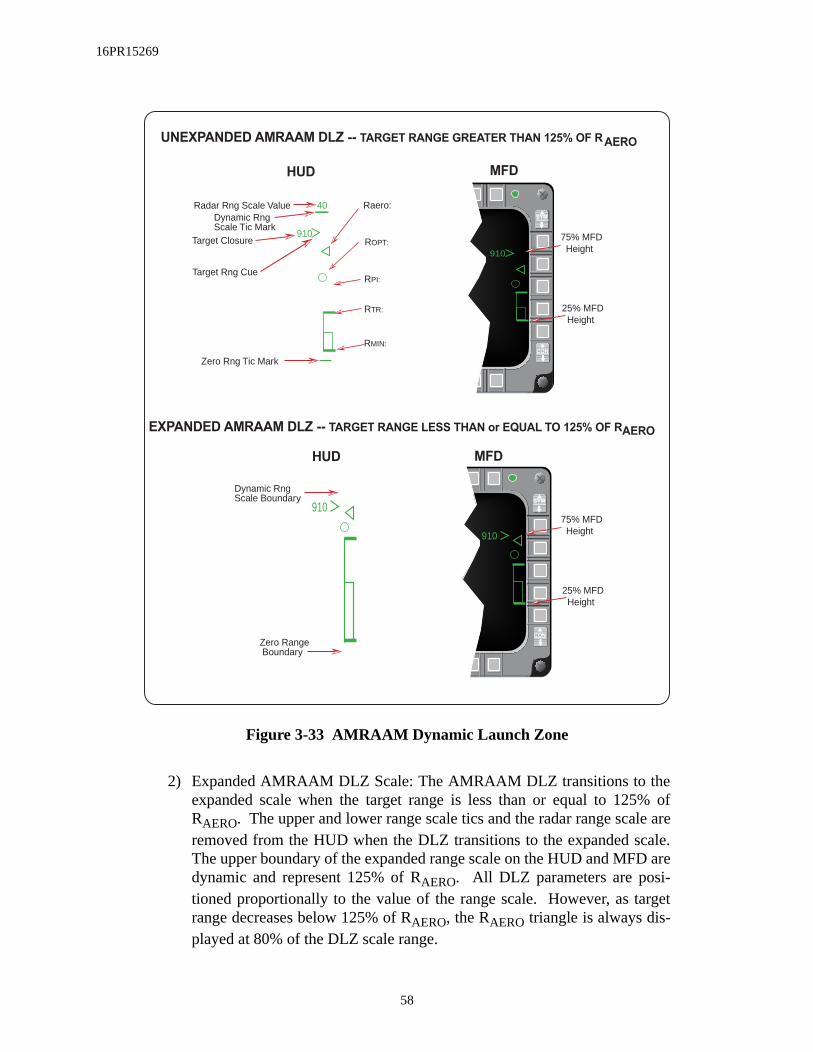
16PR15269
Figure 3-33 AMRAAM Dynamic Launch Zone
2) Expanded AMRAAM DLZ Scale: The AMRAAM DLZ transitions to theexpanded scale when the target range is less than or equal to 125% ofRAERO. The upper and lower range scale tics and the radar range scale areremoved from the HUD when the DLZ transitions to the expanded scale.The upper boundary of the expanded range scale on the HUD and MFD aredynamic and represent 125% of RAERO. All DLZ parameters are posi-tioned proportionally to the value of the range scale. However, as targetrange decreases below 125% of RAERO, the RAERO triangle is always dis-played at 80% of the DLZ scale range.
UNEXPANDED AMRAAM DLZ -- TARGET RANGE GREATER THAN 125% OF R
EXPANDED AMRAAM DLZ -- TARGET RANGE LESS THAN or EQUAL TO 125% OF R
MFD
GAIN SYM
BRT CON
910
MFD
GAIN SYM
BRT CON
910
25% MFD Height
75% MFD Height
25% MFD Height
75% MFD Height
910
40
Target Rng Cue
Raero:Radar Rng Scale Value
Zero Rng Tic Mark
Dynamic Rng Scale Tic Mark
ROPT:
RPI:
RTR:
RMIN:
Target Closure
HUD
AERO
AERO
910
HUD
Zero Range Boundary
Dynamic Rng Scale Boundary
58

16PR15269
AIM-9 DLZ Transitions (Figure 3-34):
1) Unexpanded AIM-9 DLZ Scale: The AIM-9 DLZ received minor modifi-cations to maintain consistency with the AMRAAM DLZ. At target rangesgreater than 110% RMAX1 the AIM-9 DLZ is displayed on the HUD andMFD in an unexpanded configuration. On the HUD the upper and lowerrange scale tics are displayed at their static locations and the radar rangescale digital readout is displayed above the upper range scale tic. Theremaining DLZ parameters (target range caret, RMAX1, RMAX2, RMIN2 andRMIN1) are positioned relative to the upper range scale tic which representsthe current radar range scale value and the lower tic that represents zerorange.The upper and lower boundaries of the unexpanded MFD DLZ areunmarked points located 75% (upper boundary) and 25% (lower boundary)above the bottom of the MFD display area. The upper boundary representsthe currently selected radar range scale value and the lower boundary rep-resents zero range. The remaining AIM-9 DLZ parameters are positionedrelative to the upper boundary.
2) Expanded AIM-9 DLZ Scale: The AIM-9 DLZ transitions to the expandedscale when the target range is less than or equal to 110% of RMAX1. Theupper and lower range scale tics and the radar range scale are removedfrom the HUD when the DLZ transitions to the expanded scale. Theboundaries of the expanded range scale on the HUD and MFD are dynamicand represent 110% of RMAX1. All AIM-9 DLZ parameters are positionedproportionally to the value of the range scale. RMAX1 is displayed at 91%of the total scale and remains static at that position as target rangedecreases below 110% of RMAX1.
59

16PR15269
Figure 3-34 AIM-9 Missile Dynamic Launch Zones
AMRAAM Impact Remechanization (RDP-1238)M2 displays the MFD target tail symbol when a slave launched AMRAAM has been
launched against the target. The tail symbol on the target flashes when the missile of interest goesactive. When any missile launched against a target is predicted to have impacted the target, themissile impact indication (X) is displayed over the target. The tail symbol only flashes if the mis-sile went active before impact (Figure 3-35). The missile impact indication is displayed for 13seconds (8 steady and 5 flashing).
UNEXPANDED AIM-9 DLZ --- TARGET RANGE GREATER THAN 110% OF R
EXPANDED AIM-9 DLZ --- TARGET RANGE EQUAL TO or LESS THAN 110% R
HUD MFD
GAIN SYM
BRT CON
910
25% MFD Height
75% MFD Height
MFD
GAIN SYM
BRT CON
25% MFD Height
75% MFD Height910
MAX1
MAX1
910
40
Target Rng Cue
Radar Rng Scale Value
Zero Rng Tic Mark
Upper Rng Scale Tic Mark
RMAX1:
RMIN1::
Target Closure
HUD
RMAX2:
RMIN2:
910
Upper Range Scale Boundary
Lower Range Scale Boundary
RMAX1:
RMAX2:
RMIN2:
RMIN1::
60

16PR15269
ningt go time
arget If seconds
vern-
Figure 3-35 MFD Target Symbology With AMRAAM Inflight
If multiple AMRAAMs are launched against a target and the first missile’s time remaicounts down to zero, an “X” is placed over the target symbol. If the missile of interest does noactive prior to the first missile’s impact time, the time to active (A##) is displayed as theremaining since the missile of interest is not yet active.
An (X) is placed over the target symbol when any AMRAAM launched against the ttimes out to indicate missile impact. The “X” remains for 13 seconds (8 steady, 5 flashing). another missile launched against the same target times out before the 13 seconds, the 13reinitializes for the second missile (Figure 3-36).
Figure 3-36 MFD Air-To-Air Target Symbology
The MFD target symbol flashes at 5-Hz when a breaklock is imminent. The rules going AMRAAM post launch target symbology follow:
12
12
12
12
BUGGED TRACK FILE
BUGGED TRACK FILE WITH
AMRAAM IN FLIGHT
BUGGED TRACK FILE WITH
ACTIVE AMRAAM MISSILE-OF-
INTEREST IN FLIGHT
BUGGED TRACK FILE AT
AMRAAM PREDICTED IMPACT;
MISSILE OF INTEREST OR
NON-MISSILE-OF-INTEREST
16M700
12FT11
16M700
12FT00
12
12
BUGGED TRACK FILE
BUGGED TRACK FILE WITH
AMRAAM IN FLIGHT
BUGGED TRACK FILE WITH
ACTIVE AMRAAM MISSILE-OF-
INTEREST IN FLIGHT
BUGGED TRACK FILE AT
AMRAAM PREDICTED IMPACT;
MISSILE OF INTEREST OR
NON-MISSILE-OF-INTEREST
12
12
12
LOSE
SYSTEM TRACK FILE
TRACK FILE WITH
AMRAAM IN FLIGHT
TRACK FILE WITH ALL
LOSING AMRAAM'S IN FLIGHT;
LOSE ALTERNATES WITH
TARGET ALTITUDE WHEN NOT
ALL AMRAAM'S LOSING
LOSE
12
BUGGED TRACK FILE WITH ALL
LOSING AMRAAM'S IN FLIGHT;
LOSE ALTERNATES WITH
TARGET ALTITUDE
12
BUGGED TRACK FILE AT
AMRAAM PREDICTED IMPACT
61

16PR15269
1) Display of the tail is unchanged. The target and tail flash at 5-Hz whenbreaklock is eminent.
2) Display a flashing tail (3-Hz) when the missile goes active. The target andtail flash at 5-Hz when breaklock is eminent.
3) Display of LOSE is unchanged.4) Display a flashing tail (3-Hz) with missile impact cross (X) to indicate
active missile impact. The target and tail flash at 5-Hz when breaklock iseminent. The missile impact cross is displayed statically for 8 seconds.
5) Eight seconds after missile impact: flash “X” at 5-Hz; flash tail at 3-Hz ifmissile is active; flash target, tail and “X” at 5Hz if breaklock is imminent.
6) Display target, tail and “X” steady to indicate a slave launched non-activemissile impact. Target and tail flash at 5-Hz and “X” steady when break-lock is imminent.
7) Eight seconds after a slave launched non-active missile impact, “X” flashesat 5-Hz. Flash target, tail and “X” at 5-Hz if breaklock is imminent.
New AMRAAM Versions (RDP-645)M2 incorporates AIM-120B and ITVB (Integration Test Vehicles for AIM-120B) into the
SMS inventory. The controls, displays, and symbology for the AIM-120B (store mnemonicA120B) are basically the same as for the AIM-120A. The store mnemonic for the B missile ITV isITVB. The Dynamic Launch Zone (DLZ) for AIM-120B is the same as for the AIM-120A; how-ever, the performance of the AIM-120B differs from the performance of the AIM-120A.
The AIM-120B is selectable as a unique missile type. The selection of weapon type ismodified such that when the last missile of the current type is launched, the aircraft will select anew weapon type that is of the same category (short vs. medium range) if possible.
The A120B mnemonic was added at OSB #7 on the SMS menu-driven Data Entry page(Figure 3-37). The ITV mnemonic was moved from OSB #7 to OSB #9 and changed to ITVA.ITVB was added at OSB #10. The target size mnemonic was moved from OSB #17 to OSB #18on the SMS Base page.
The AIM-120’s and ITV’s are loaded on LAU-129 (MRL) and LAU-129 (MRLW).
62

16PR15269
Figure 3-37 New AMRAAM Mnemonics On The SMS Inventory Entry Page
AIM-120 Active Range Indications (993)Tactical information displayed by the AIM-120 DLZ has been improved. Both A-Pole
(ownship to target range when the AMRAAM goes to the Medium PRF (MPRF) mode) and F-Pole (ownship to target range at missile impact) ranges were added to the DLZ (Figure 3-38).
A-Pole or F-Pole range indications, for the missile on the rail, were added to the DLZbelow the Target Range Cue caret and Closure Rate indication. Indications are in NM with an Msuffix for A-Pole (A is not used to avoid confusion with AMRAAM active indications) and an Fsuffix for F-Pole.
Figure 3-38 AMRAAM DLZ With Active Range Indications
GAIN SYM
BRT CON
SWAP SMS WPN S-J
STBY
A120B
A120A
ACMI
EACMI
A-9LM
A-9NP
MAU
RTN
ITVB
ITVA
W
SELECT
WEAPON FOR
STATIONS
2 8
X X
1 MRL
MNEMONIC
FOR
AIM-120B
MNEMONIC
FOR ITVB
MNEMONIC
FOR ITVA
16M
15MA04
910"A"/"F"-POLE RANGEFOR MISSILE ON RAIL(HUD #61)
TIME REMAINING *FOR MISSILE IN FLIGHT
Raero
WINDOW: HUD #32, MFD #15 WINDOW: HUD #37
CLOSURE RATE* (HUD #33)
"A"/"F"-POLE RANGEFOR MISSILE IN FLIGHT
* NO CHANGE
63

16PR15269
A-Pole or F-Pole range indications for the missile in-flight are added immediately belowthe DLZ. These indications are for current conditions and will update as the target maneuvers. Ifthe in-flight missile is losing, this display is blanked. This HUD window was previously used toshow missile-on-the-rail time-remaining indications.
Time remaining indications for the in-flight missile with the longest time until impactagainst the bugged target is still displayed in the second field below the DLZ. A prefix identifiesthe time remaining as follows: T - time until impact, A - time until active, M - time until MPRF,and L - losing missile time until termination.
AIM-120 Launch Against Marginal Track Indications (RDP-986)This change allows an AMRAAM launch sequence to continue if targeting data (e.g.,
angle, range, velocity, etc.) become invalid between the time the weapon release button is firstdepressed and the missile comes off the rail. Normal operation of an AMRAAM launch is notaffected by this change.
Marginal FCR track conditions could occur if the target goes into the notch or radar jam-ming is present. Launch cannot be initiated unless valid targeting data are available; a launchcommand is ignored when these elements are invalid. However, if an AMRAAM launch isalready in progress when data elements become invalid, the last valid data is frozen for use incompleting the launch.
AMRAAM Burn (RDP-964)To prevent missile damage when an AMRAAM is physically loaded on a station with the
SMS inventory indicating an AIM-9 missile, the avionics system will fail the station and set theweapon status to Malfunction (MAL).
Flight members need to select different AMRAAM missile ID numbers in order todeconflict missile data link and missile radar frequencies. The missiles receive their ID assign-ments in the order launched (Table 3-1). The ID sequence is based on the ID number selected onthe SMS Control page OSB #17 (ID).
Table 3-1 AMRAAM Missile ID Assignment
ID NO. SELECTED MISSILE IDASSIGNMENT
3 2-1-6-5-2-1-6-5
1
7-4-1-2-7-4-1-22
6-5-8-3-6-5-8-3
3-8-7-4-3-8-7-44
64

16PR15269
r
rgetd
LOSE Cue In HUD Remechanization (RDP-1162)The MMC provides post launch cues for each AMRAAM that has been slave launched
against a system track file. The cues are based on missile launch status, the phase of the missileflight, and when impact on the target is predicted. When target impact is not predicted, the MMCprovides LOSE indications on the HUD and MFDs. When all AMRAAM missiles launchedagainst the Target Of Interest (TOI) are in a LOSE condition, “LOSE TOI” is displayed in themiddle of the HUD (Figure 3-39). “L##” is displayed under the DLZ, where “##” is the timeuntil termination for the missile of interest, and “LOSE” alternates with the target altitude undethe TOI target symbol on the MFD. If any missile launched is predicted to hit the TOI, “LOSETOI” will not be displayed. When all AMRAAM missiles launched against a particular taother than the TOI are in a lose condition, “LOSE” is displayed in the middle of the HUD an“LOSE” alternates with target altitude under the target symbol on the MFD. “LOSE TOI” haspriority over “LOSE” in the HUD.
Figure 3-39 HUD AMRAAM LOSE Cue
450
R 19,800
2.5
C
1.024.12 MRM
AL 1200
115>30014:43
ARM
22,500
68012M
F016.0
24
12ML12
LOSE TOI
M-POLE OR F-POLE RANGEFOR MISSILE OF INTERESTLAUNCHED AT BUG
Raero (KINEMATIC RANGEFOR MISSILE ON RAIL)
"LOSE TOI" INDICATES LOSESTATUS FOR ANY MISSILES OF INTEREST LAUNCHED ATBUG. "LOSE" FOR NON-BUGTARGETS
INDICATES LOSE STATUS OR CURRENT STATUS FOR MISSILE OF INTERESTLAUNCHED AT BUG
A-POLE OR F-POLE RANGE FOR MISSILE ON RAIL
65

16PR15269
THIS PAGE INTENTIALLY LEFT BLANK
66

16PR15269
pro-and A- Track
d on theaster
/-1.7Whiteols.g data. either aicted
ol theMode
Baseower ispowerndbyr
mode
SECTION 4 - AIR-TO-GROUND
This section introduces the following Air-to-Ground enhancements:
• LANTIRN Targeting Pod FLIR Interface• Targeting Pod TV• Attitude Advisory Function (AAF)• Generic RECCE Pod II• BAF RECCE Upgrades• New Strafe Pipper/Reticle• Maverick Missile Launch Envelope (MLE)• Maverick Video Initiation• EO-VIS Auto SOI Sequence• HARM• Mark-84 Transonic Algorithm• Update CBU-87 Algorithm
LANTIRN Targeting Pod FLIR Interface (RDP-864)The Block 40T5 generic Targeting Pod (TGP) capability is incorporated into the M2
duction tape. The targeting pod contains a passive Infrared (IR) sensor that can track A-A G targets. Tracking techniques include Point Track (based on a high-contrast edge), Area(based on intensity levels at various points in the video), and Computed Rates Track (baselast known angular rate of change for the target). The TGP operates in NAV, A-A, or A-G mmode. The TGP has: two optical Fields of View (FOV), wide (+/-6 deg.) and narrow (+deg.); one electronic expansion (EXP) FOV (0.69x0.69) when selected; two IR polarities (Hot and Black Hot); and a TV sensor option, plus a variety of brightness and contrast contr
The TGP has a laser ranger that can be fired at a target for very accurate ranginFor stationary targets, the TGP can compute a range using angle rates. The laser can below intensity “eye-safe” training laser (indicted by a T) or high accuracy combat laser (indby an L). The appropriate character is displayed near the bottom of the TGP format.
WARNINGThe combat laser can cause eye damage out to 12 miles.
Control of the TGP is available both hands-on and hands-off. For hands-on contrTGP must be the SOI. Hands-off controls are via the MFDs TGP Base page, the A-A Menu page, the A-G Mode Menu page, and the TGP Control page.
Selecting the TGP mnemonic on the Master Format Menu page will access the TGPpage. The TGP OFF page is displayed if there is no power applied to the targeting pod. Papplied to the targeting pod by placing the right Hard Point (HDPT) switch on the sensor panel to the RIGHT HDPT position. When power is first applied, the TGP is placed in Sta(STBY) mode while the system cools and “NOT TIMED OUT” is displayed in the upper centeof the TGP Base page. After the Forward Looking Infrared (FLIR) system has cooled, “NOTTIMED OUT” is removed from the display and the pod transitions to the commanded sub(A-G, A-A or STBY). The pod FLIR sensor normally takes 8 to 10 minutes to cool.
67

16PR15269
OFF”
After
There are four LANTIRN TGP pages: OFF, Base (A-A, A-G), Control (CNTL) andMode Menu. The TGP Operational Flight Program (OFP) ID is displayed on the DED OFP page3 only after TGP time-out.
LANTIRN TGP Modes:The TGP supports the following five modes:
1) Off (OFF) 2) Standby (STBY)3) Built-In-Test (BIT)4) Air-To-Ground (A-G) 5) Air-To-Air (A-A)
The TGP OFF page (Figure 4-1) is displayed when the right HDPT switch is OFF, or theTGP is not communicating on the MUX Bus. These conditions are indicated by the “TGP mnemonic in the center of the MFD.
Figure 4-1 TGP OFF Page
The TGP Built-In Test (BIT) mode is accessed from the MFDs Test Format page. completing the BIT, the TGP returns to the last commanded mode.
During BIT, the TGP provides the following servo checks:
1) FOCUS: Image focus changes and then returns to normal2) FOV: FOV changes from WIDE to Narrow (NARO) to Expand (EXP)
GAIN SYM
BRT CON
SWAPTGP SMS
SIM
OFF
TGP
C
Z
W
BARO
68
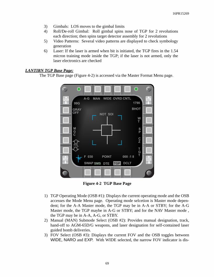
16PR15269
3) Gimbals: LOS moves to the gimbal limits4) Roll/De-roll Gimbal: Roll gimbal spins nose of TGP for 2 revolutions
each direction; then spins target detector assembly for 2 revolutions5) Video Patterns: Several video patterns are displayed to check symbology
generation6) Laser: If the laser is armed when bit is initiated, the TGP fires in the 1.54
micron training mode inside the TGP; if the laser is not armed, only thelaser electronics are checked
LANTIRN TGP Base Page:The TGP Base page (Figure 4-2) is accessed via the Master Format Menu page.
Figure 4-2 TGP Base Page
1) TGP Operating Mode (OSB #1): Displays the current operating mode and the OSBaccesses the Mode Menu page. Operating mode selcetion is Master mode depen-dent; for the A-A Master mode, the TGP may be in A-A or STBY; for the A-GMaster mode, the TGP maybe in A-G or STBY; and for the NAV Master mode ,the TGP may be in A-A, A-G, or STBY.
2) Manual (MAN) Submode Select (OSB #2): Provides manual designation, track,hand-off to AGM-65D/G weapons, and laser designation for self-contained laserguided bomb deliveries.
3) FOV Select (OSB #3): Displays the current FOV and the OSB toggles betweenWIDE, NARO and EXP. With WIDE selected, the narrow FOV indicator is dis-
GAIN SYM
BRT CON
SWAP SMSSMS TGP DCLT
A-G
POINT
NOT SOI
1790
GRAY
OFF
OVRDWIDE
W
BHOT
M
G
C
F 030 000 :1 8
DTE
CNTL
T
G
T
C
Z
S
P
W
T
99G
77L
MAN
69

16PR15269
lays
iswith
is
the for-
initial
rsor
nsityl
evel
olled
dis-
ain is
s dis-modey indi-e to
at. If TGP
played. The FOV can also be changed hands-on by making the TGP the SOI andDepressing and Releasing (D&R) the pinky switch to toggle the options.
4) Standby Override (OVRD) Select (OSB #4): Commands the TGP to STBY modeand “OVRD” highlights. With OVRD highlighted, “STBY” is displayed at OSB#1 for all Master modes.
5) Control Page Select (OSB #5): When selected “CNTL” highlights and dispthe Control page.
6) Radar Altitude: Radar altitude is displayed above the OSB #6 mnemonic.7) Display Polarity Select (OSB #6): Alternates between White-Hot (WHOT) and
Black-Hot (BHOT) or WHOT, BHOT, and TV depending on which TGP loaded. With BHOT selected, hot objects appear as black on the display; WHOT selected, hot objects appear white.
8) Tracking Polarity Select (OSB #7): Alternates between Neutral Track (NT) andWhite Track (WT) or NT, WT, and Black Track (BT) depending on which TGPloaded. NT allows both white and black targets to be tracked; with WT selected,only white targets are tracked.
9) Snowplow (SP) Sighting (OSB #8): When selected the TGP is slaved to ½selected FCR range until the selected waypoint is ground-stabilized via TMSward. “SP” is highlighted when selected.
10) Cursor Zero Select (OSB #9): Removes previous adjustments made to thecursor position.
11) Sighting Point (OSB #10): Provides the following sighting options and cuposition features:
a) STP/TGT – Steerpoint and target direct aim point sightingb) OA1/OA2 – Offset aim point sightingc) IP – Visual initial point sightingd) RP – Visual reference point sighting
12) FLIR Manual Level Adjust (OSB #16-#17): Decreases/increases the intelevel when Manual Gain/Level Control (MGC) (OSB #18) is selected. Video leveshifts the video range.
13) Manual/Auto Gain Select (OSB #18): Alternates between Manual Gain/LControl (MGC) and Automatic Gain/Level Control (AGC). With AGC selected,the level adjust gain label (OSB #16-#17) is removed and gain/level is contrautomatically.
14) Gray Scale Select (OSB #20): Alternates between GRAY ON and GRAY OFF.With GRAY ON selected, the gray scale is displayed across the bottom of theplay.
15) GAIN Control (GAIN Rocker): Increases/decreases the gain when Manual Gselected (OSB #18)
16) Time to Steerpoint/Release/Impact: Time to steerpoint, release, or impact iplayed in the lower right corner of the TGP page depending on the master and whether a weapon has been released. In NAV master mode, this displacates time to steerpoint. In A-G master mode, this display indicates timweapon release, then displays the estimated time until impact.
17) SPI Range: The SPI range is displayed in the lower portion of the TGP formthe range is determined by the TGP laser, an L precedes the range. If the
70

16PR15269
s 0-t theon. Agreeshe 6-ates posi-
determines the range, a T precedes the range. If any other sensor provides therange, only the range is displayed.
18) Situation Awareness Indicator (SAI): A small square appears on the TGP formatindicating TGP LOS in azimuth and elevation. The square is positioned aroundthe center of the display at its azimuth relative to the nose of the aircraft, and itsposition from the center of the display indicates its elevation with the center repre-senting -90 degrees elevation and the edge 0-degrees. Some examples may helpclarify this scheme: The 12-o’clock position at the top of the display indicatedegrees relative azimuth and 0-degrees elevation; the 3-o’clock position aright edge of the display indicates 90-degrees azimuth and 0-degrees elevatiposition half way between the edge and center of the display indicates -45-deelevation; and the center of the display indicates -90-degrees elevation. To’clock position half way between the center and bottom of the display indic180-degrees azimuth and -45-degrees elevation. Figure 4-3 shows TGP LOStions relative to the aircraft.
Figure 4-3 TGP LOS Positions Relative To The Aircraft
TGP Control Page:The TGP Control page (Figure 4-4) allows access to seldom changed functions. The
control page is accessed by depressing CNTL (OSB #5). When the Control page is displayed,“CNTL” is highlighted.
AZ 0 deg
EL 0 deg
AZ 90 deg
EL 0 deg
AZ 30 deg
EL -45 deg
AZ 0 deg
EL -90 deg
AZ -90 deg
EL 0 deg
SAI
TGP FORMAT
71

16PR15269
Figure 4-4 TGP Control Page
1) Tank Recognition Threshold (THLD) (OSB #6): Selects tank recognition probabil-ity threshold choices are LOW, MED1, MED2, and HIGH.
2) Video Instrumentation Select (V/INST) (OSB #8): When selected on the ground,the azimuth and elevation of the TGP seeker head are displayed on the Controlpage
3) FOV Select (OSB #16): Alternates between Manual and AUTO. With AUTOselected and target range decreasing, the TGP defaults to WIDE FOV; when thetarget is too large to track in NARO, it changes to WIDE
TGP Mode Menu Page:The TGP Mode Menu page (Figure 4-5) provides switching between the TGP modes.
Depressing OSB #1 on the TGP Base page accesses the TGP Mode Menu page. The TGP ModeMenu page only displays the modes available for the selected Master mode. In the Nav Mastermode, the TGP may be commanded to A-A, A-G, or STBY.
GAIN SYM
BRT CON
SWAP SMSTGP DCLT
A-G
POINT
1790
OVRDWIDE
F 030 000 :1 8
DTE
V / INST
FOV
AUTO
CNTL
W
THLD
LOW
MAN
72

16PR15269
REAcom-OINT
faults toss a
e. If OSBrget isLOS is
Figure 4-5 TGP Mode Menu Page
TGP Tracking:The TGP includes processing that performs as an automatic tracker. The tracker operates
in three modes: POINT, AREA, and Computed RATES. Tracker mode information is imbeddedin the TGP video. During any tracking mode, the cursor is used to reposition the LOS. When cur-sor inputs stop, the TGP returns to the mode it was in prior to applying the cursors. This allowsfine tuning of the tracked point.
POINT Track: The TGP POINT Track mode is capable of tracking single targets. Thetargets require well-defined edges. An edge in the TGP video exists because of a difference intemperature between the target and its background. When POINT Track is established, a boxgrows from the center of the crosshairs until the edges of the target are enclosed in the box.“POINT” is displayed below the crosshairs, indicating that track has been established.
Designating with TMS-forward and hold, when the TGP is the SOI, commands Atrack to stabilize the LOS. Releasing TMS-forward commands POINT Track. TMS-aft mands the TGP to break track and return to the SLAVE mode. If the target cannot be Ptracked because the target does not have sufficient edge detail, the TGP automatically deAREA Track. Once the TGP has changed to AREA Track, it will not return to POINT unlenew POINT Track command is initiated.
POINT Track can be initiated only on objects that appear white in the video imagtrack is desired on a black object, the display polarity must be changed via TMS-left or D&R#6 (current polarity). Track on the now-white object can be established. When a white tatracked and the polarity is changed to black, the track should be maintained unless the moved.
GAIN SYM
BRT CON
SWAP SMS TGP S-J
A-G WIDE
A-G
OVRDMAN
A-A
STBY
W
NOT SOI
73

16PR15269
ight.rd isstabi-anding
ight
theucture groundforma-e TGParget.Com-
lectedty con- TGP
round-otherhedja-
masklashes
lew theL/ld use
intaino track
The TGP tracker continuously updates the tracker box such that, when the aircraft ismaneuvered, the tracker box changes to the new viewing aspect of the target. If the target is mov-ing and passes behind another object (e.g., a building), the tracker box may expand to encloseboth the target and the object it is passing behind. When the target exits from behind the object,the tracker may reacquire the target or drop track on the target and track the new object. If the lat-ter case occurs, a small cursor input can move the LOS back to the desired target for reacquisition.Which of these conditions occur is dependent on the target, background, and the new object.
AREA Track: The TGP AREA Track mode tracks targets that are not POINT trackable.Large targets, scenes that do not contain targets with well-defined edges, and targets that do nothave significant IR signatures are examples of situations where POINT Track might not maintaina stable track. AREA Track may also be used for targets that are point trackable but where AREATrack is desired (e.g., to place the center of the LOS at a particular point). When in AREA Track,“AREA” is displayed on the TGP format below the crosshairs.
AREA Track can be accessed in two ways: 1) TMS forward and hold, or 2) TMS rAREA Track is commanded as long the the TMS-forward is held. When TMS forwareleased, POINT Track is commanded. The benefit of commanding AREA Track is that it lizes the scene and makes establishing POINT Track easier. The second method of commAREA Track allows AREA Track to be commanded without the TMS being held. TMS-rcommands AREA Track only if AGM-65D/G missiles are not selected.
Computed RATES Track Mode: Computed RATES is entered automatically when POINT and AREA trackers lose target track. This happens most often when the aircraft stror stores mask the target. The Computed RATES Track mode enables the LOS to remainstabilized at the last point tracked. The TGP accomplishes this by using aircraft attitude intion and information about the last point tracked. When the masked condition clears, thLOS will be close to the last target tracked. The pilot must manually reacquire the t“RATES” is displayed below the crosshairs when the TGP is in Computed RATES Track. puted RATES is not pilot selectable.
TGP Masking: Since the combat mode laser is not eye-safe, even for scattered/refenergy, it is imperative that the laser beam not strike the aircraft. To accomplish this safesideration, the TGP determines if it is looking at the aircraft structure or stores. When theLOS is pointed at the aircraft, laser fire is inhibited. The mask zone blocks off the area suring the wing tanks on stations 4 and 6 and a LANTIRN navigation pod on station 5L. All stores are blocked by the wing tanks. Indications of a masked condition includes an “M” on tTGP format next to the L-mnemonic in the bottom right portion of the MFD and “MASK” acent to the flight path marker on the HUD.
There is a warning zone outside of the actual mask zone which alerts the pilot that acondition is approaching. When in the warning zone, the TGP crosshairs flash and MASK fon the HUD.
Navigation:In the navigation master mode, the TGP A-G mode can be used to determine and s
SPI as well as use the following functions: TGP FIX, TGP ACAL, TGP Mark, HUD Fix/ACAMark (laser ranging). Additionally, any Nav function that uses radar AGR as a sensor couthe TGP laser range instead.
If the TGP is tracking an A-G target, the target is the SPI by default. In order to mathe F-16 single LOS concept, if the SOI is moved to the TGP and the pod is commanded t
74

16PR15269
rotaryguin useon thee TGPds the with
laves to
or slew, the FCR is sent a break track (RTS) and its LOS is commanded to the TGP LOS. Like-wise, if the TGP is tracking and the SOI is moved off the TGP page, and either the FCR is com-manded to track or slew inputs are received, the TGP is commanded to break track. If neither theTGP nor the FCR are tracking and the TGP obtains a valid laser range, the location of the SPI isdetermined using the laser range data.
TGP was added to the sensor rotary on the FIX, ACAL, and MARK DED pages andoperates identical to the FCR option. The TGP laser may be used for ranging during a HUD FIXupdate. FCR AGR is overridden by firing the laser during an update.
TGP A-G Mode:The A-G mode is used against preplanned targets as an aid for identifying, locating, and
acquiring ground targets, and to hand-off targets to Maverick missiles. In the A-G mode, A-G orSTBY are the only TGP modes available.
Use of the TGP, during A-G preplanned delivery options (CCRP, LADD, EO-PRE, PengRDR), to determine the SPI, is similar to navigation operations. With the SOI on the TGP format,the TGP may be commanded to track a target, making it the SPI, or the SPI can be slewed by plac-ing the cursor over the SPI and designating.
TGP laser data can be usedduring A-G visual deliveries. Pulling the trigger to the firstdetent fires the laser, pulling the trigger to the second detent latches the laser for 30 seconds (onlyin CCIP or CCIP Rockets). When dropping LGB’s, the laser fires automatically at the enteredlaser start time and continues four seconds (30 seconds for GBU-24) after the computed weaponimpact time.
The TGP can hand-off targets to the Maverick missiles for A-G E-O deliveries. If a Mav-erick D or G is loaded on a LANTRN compatible launcher, and the TGP is commanded to track,the TGP takes control of the Maverick and hands-off the target to the missile. Once the target ishanded-off, the TGP LOS can be slewed to a new target and commanded to track. The TGP againattempts to hand-off the new target to a second Maverick missile.
When the TGP is in the A-G mode with an AGM-65D/G missile on a LANTIRN capablelauncher as the selected weapon, a 10-mr box is displayed on the HUD at the target LOS for eachtarget located by the TGP. When the TGP successfully hands-off a target to an AGM-65D/G, the10-mr box becomes a 10-mr circle. When the TGP determines the target is in range, a tic is dis-played on the bottom of the symbol. When two LOSs are established, a small numeric "1" indi-cates the next to shoot LOS and a "2" indicates the following LOS. When the TGP is in A-G andthe selected weapon is other than an AGM-65D/G missile on a LANTIRN capable launcher, a 10-mr box with a 1-mr pipper is displayed representing the target. The TGP Target Locator Line(TLL) is displayed when A-G targets are outside the HUD FOV. The TLL is a 40-mr dotted lineextending from the boresight cross at the relative bearing to the target. A number representingtotal angle off the nose to the target is displayed adjacent to the boresight cross.
In Penguin RDR modes, the TGP is commanded to the target LOS. The TGP Base pagedisplays “TGT” in the sighting point rotary. The FCR Base page changes the sighting point to TGP. Penguin radar modes alway move the target independent of the state of the Penrotary. Slewing the TGP with the FCR Penguin use rotary set to waypoint has no effect FCR LOS. Slewing the FCR, with the Penguin use rotary set to waypoint does not affect thLOS. However, slewing the TGP with the FCR Penguin use rotary set to target commanFCR to break track and the FCR LOS slaves to the TGP LOS. Likewise, slewing the FCRthe Penguin use rotary set to TGP commands the TGP to break track and the TGP LOS s
75

16PR15269
et inde-silese FCRverridelow the
e inde-OS is TD
pen- track-
to theslaved
r to beP. For rota-s,TGP
the FCR LOS.In other non-Maverick visual delivery options like CCIP, DTOS, and Peng HUD, the TGP
LOS is slaved to the SPI LOS. If the laser is fired and a valid range is returned, the TGP laserrange is used for the SPI calculations rather than the FCR AGR range data.
TGP A-A Mode:The TGP A-A mode provides visual target identification and tracking of A-A targets. In
A-A the TGP is initially commanded to the FCR LOS if the FCR is tracking an A-A target. Whenthe TGP is not the SOI and the FCR is not tracking a target, the TGP LOS is positioned to 0degrees azimuth and –3 degrees elevation. The TGP can track and maintain an A-A targpendent of the FCR LOS, resulting in two A/A TD boxes/TLL's. The FCR and/or AIM-9 miscan be slaved to the TGP LOS. The AIM-9 missile can be slaved to either the TGP or thLOS. The pilot has the option to fire the laser for accurate ranging data, but it does not othe slant range sent by the FCR. Instead the TGP laser range is displayed immediately beslant range.
Once the TGP has been commanded to track, the TGP LOS and the FCR LOS arpendent. The TGP LOS is shown as a dotted 50-mr A-A TD box in the HUD. If the TGP Loutside the HUD field-of-view, a dotted TLL and target angle are displayed. The FCR A-Abox is a solid 50-mr box.
Although the TGP LOS is independent of the FCR LOS, depressing TMS right (indedent of SOI) commands the FCR into ACM boresight along the TGP LOS when the TGP ising and the FCR is in ACM.
If an AIM-9 is the selected weapon and is caged in the Slave submode, it is slavedLOS of the SOI sensor. Whenever the AIM-9 LOS is within 1.5 degrees of the sensor it is to (correlation), a "C" is placed to the left of the target angle indicator for that sensor.
Targeting Pod TV (RDP-1170)OSB #6 on the TGP Base page (Figure 4-2) was modified to allow the TGP senso
swapped between IR (baseline) and TV when the aircraft is loaded with a TV capable TGIR only TGPs, OSB #6 toggles between WHOT and BHOT; For TV capable TGPs OSB #6ries tetween WHOT Å BHOT Å TV. OSB #7 selects the tracking polarity. For IR only TGPOSB #7 toggles between Neutral Track (NT) and White Track (WT). With a TV capable load, the OSB #7 rotary steps between NT Å WT Å BT (Black Track).
Attitude Advisory Function (AAF) (RDP-1502)An attitude advisory is triggered when all of the following conditions exist:
1) TGP format is displayed2) TGP mode is A-G3) INS attitude data is valid4) Aircraft exceeds any of these defined attitudes:
a) Bank > 75 deg; Pitch < 0 deg.b) Pitch < -20 deg
When these conditions are met, a flashing rectangular box with the double set of words “CHECKATTITUDE” (Figure 4-6) is displayed on both MFDs (all formats). The attitude advisory is dis-
76

16PR15269
k Atti-
#s 1-4,ected toepres-
abled whenever one or more of the four conditions listed above no longer exist. The “Chectude” box default color is red and is DTC loadable.
Figure 4-6 Attitude Advisory For MFD Formats
Generic RECCE Pod II (RDP-865)A new “TEST” button was added to the RECCE Base page at OSB #5 (TEST). Depres-
sion of the test button will bring up the RECCE Test page and the labels adjacent to OSB 6-10 and 16-20 are provided by the RECCE Pod (Figure 4-7). These buttons are then connthe RECCE Pod via the 1553 Mux Bus and function as commanded by the RECCE pod. Dsion of OSB #5 (RTN) on the Test page returns to the RECCE Base page.
GAIN SYM
BRT CON
SWAP SMSSMS TGP DCLT
A-G
POINT
NOT SO I
1790
GRAY
OFF
OVRDWIDE
W
BHOT
M
G
C
F 030 000 :1 8
DTE
CNTL
T
G
T
C
Z
S
P
W
T
99G
77L
MAN
CHECK
ATTITUDE
CHECK
ATTITUDE
77

16PR15269
Figure 4-7 RECCE Pod Access Via Test Button
BAF RECCE Updates (RDP-1700)Based on Belgium Air Force (BAF) requirements, the MMC will pass/set the following
interface to the EWMS:
1) Additional aircraft attitude (INS) data2) Addition of data for RECCE image marking3) Time-of-day/current time4) Height-Above-Target (HAT) information5) Landing gear status
GAIN SYM
BRT CON
GAIN SYM
BRT CON
SWAP SMS RCCE DCLT
STBY
VT
SEC
FRZ
IRLS
PRI
FILE
M00
W
RCD
FWD
LAS
TEST
18 17
OSB LABELS ARE SENT
FROM THE RECCE POD
RECCE TEST PAGE
RECCE BASE PAGE
SWAP SMS RCCE
RTN
TEST
RTN
78

16PR15269
renceto 15-ted in
New Strafe Pipper/Reticle (RDP-592)M2 provides a new Strafe (STRF) pipper that is suitable for both the PGU-28 long range
bullets and the shorter-range M-56 bullets. When in STRF, the avionics system displays a load-able/programmable MFD ammo in-range value for the HUD in-range cue. The SMS page dis-plays the slant in-range bullet data and mnemonic adjacent to OSB #9. Selection/modification ofthe bullet in-range value is via OSB #9 on the SMS STRF Base page. When no values areentered, initialization bullet in-range values are 12,000 feet for PGU-28 and 4,000 feet for M-56ammunition.
The new strafe pipper, ranging reticle and associated symbology (Figure 4-8) consist of:
1) 50-mr diameter strafing reticle2) 40-mr diameter strafing reticle3) 2-mr diameter in-range cue4) 5-mr length tic to designate slant range5) moving target indices at 3 and 9 o’clock for ground targets6) a bullet track line.
Figure 4-8 HUD Strafe Pipper
The Moving Target Indices (MTI) are roll stabilized and scaled to provide an aiming refeagainst a ground target moving at 30 knots perpendicular to the LOS. The MTI is limited mr on either side from the center of the CCIP pipper. The new strafe pipper/reticle is illustraFigure 4-9 at various ranges for both the M-56 and PGU-28 bullets:
450
1.0
C
0.684.1STRF F 030
003>05000: 24
ARM
1,500
*
BULLET TRACK LINE2-mr IN-RANGECUE
50-mr STRAFE RETICLE MOVING TARGET
INDICES
79

16PR15269
Figure 4-9 Strafe Pipper/Reticle For M-56 And PGU-28 At Various Ranges
Maverick Missile Launch Envelope (RDP-306)M2 incorporates the Maverick Missile Launch Envelope (MLE) for the Electro-Optic (E-
O) modes. An in-range caret is positioned on the HUD and MFD DLZ displays at target range.Aircraft horizontal range to the system target is used for the in-range computations.
The A-G MLE scale is available when all of the following are true:
1) Selected weapon is a Maverick A, B, D, or G2) Horizontal range to the target is less than 20-NM
3) Target is within +/- 30o of the aircraft X-axis4) INS data is valid5) Central Air Data Computer (CADC) data is valid6) And one of the following are true:
a) Submode is E-O Preplanned, orb) Submode is E-O Bore, orc) Submode is E-O Visual post designate
The MLE is computed using aircraft airspeed, Height Above Terrain (HAT), and perfor-mance parameters for the selected Maverick. When the weapon station is changed, the MaverickMLE range caret remains referenced to the system target. The missile footprint is displayed as thedelta between RMAX and RMIN. The Maverick boresight cross on the MFD E-O WPN page isflashed when the missile determines that the target cannot be properly tracked.
The HUD A/G MLE is a modified CCRP Loft Scale. A number and caret representingthe horizontal range to the target in nautical miles moves vertically down the missile footprintscale. When the caret is positioned between the max and min range tics, the missile is in range
MAX AMMO IN-RANGE VALUE = 6,600 FEET
12,000 Feet 8,000 Feet 6,600 Feet 5,000 Feet
MAX AMMO IN-RANGE VALUE = 14,000 FEET
10,000 Feet14,000 Feet24,000 Feet
12,000 Feet
50mR RETICLE
40mR RETICLE
IN-RANGE CUE
20,000 Feet
80

16PR15269
e. It
(Figure 4-10). A similar A/G MLE is displayed on the MFD E-O Weapon page.
Figure 4-10 Maverick MLE in the HUD
Maverick Video Initiation (RDP-1240)Maverick video is toggled “ON” and “OFF” when uncage is depressed on the throttl
is no longer turned on at entry into the A-G mode or after timeout.
EO-VIS Auto SOI Sequencing (RDP-1164)With the SOI in the HUD and EO-VIS selected, the first TMS up (designate) ground stabi-
lizes the TD box and allows cursor slews to refine the TD box position. A second designatemoves the SOI to the WPN format.
HARM (RDP-1200)The High Speed Anti-Radiation Missile (HARM) (AGM-88) (Figure 4-11) is a program-
mable, frequency adjustable, air-to-ground, anti-radiation missile that may be loaded on weaponstations 3, 4, 6 and 7, however, it is only flight certified on stations 3 and 7. The HARM isdesigned to detect and attack enemy air defense systems across the RF spectrum.
Figure 4-11 High Speed Anti-Radiation Missile (HARM) (AGM-88)
HARM requires a Launcher Avionics Package (LAP), which consists of an AircraftLauncher Interface Computer (ALIC) installed inside the LAU-118 launcher pylon. The ALICprovides the interface between the weapon and aircraft.
The HARM Test Vehicle (HTV) is a HARM with the warhead replaced by a telemetrypackage.
4
20
HORIZONTAL RANGE TO TARGET
RANGE SCALE
MAXIMUM MISSILE RANGE (Rmax)
MINIMUM MISSILERANGE (Rmin)
81

16PR15269
”,t pro-
DTE Loading of HARM data:HARM data is loadable from the DTE page via OSB’s labeled “ELINT”, “INV”, “PROF
and “MSMD”. The data consists of HARM threat data, stations loaded, selected mode/flighfile, and the threat symbology tables in the DED HARM page and HARM WPN format.
SMS HARM Base Page:The HARM Base page (Figure 4-12) contains the following unique controls:
1) Tertiary Table (TER TBL) OSB #2: Rotaries between TBL0, TBL1,TBL2, and TBL3. TBL0 loads only the selected threat and table.TBL1,2,3 Load the primary threat table and the tertiary table.
2) Weapon selection OSB #6: “AG88” is displayed when HARM is theselected weapon, “HTV” is displayed when an HTV is selected.
3) Missile Power (PWR) OSB #7: Toggles between PWR ON and PWR OFF. 4) BIT OSB #8: Commands BIT at the selected station. Automatic BIT is
commanded on all ALIC/HARM stations at power up. Station number isreplaced with “F” for failed missiles or “D for degraded missiles.
5) Selective Jettison (S-J) OSB #11: S-J applies power to all HARM loadedstations.
6) Gyro Test (GT) OSB #18: Toggles between GT ON and GT OFF. GT isonly displayed for HARMs with a telemetry unit (HTVs) and Master Armin SIM.
7) Command-Destruct (CD) Enable OSB #20: Displayed only with MasterArm in ARM or OFF. Turns CD ON. Can only be disabled by an inven-tory change. HARM Test Vehicles (HTV) can be self-destructed from aground station when enabled.
82

16PR15269
r man-Manual
anuals in the and
FCs HAS, theteps to.ch of threetable.at des-
Figure 4-12 SMS Base Page With HTV Selected
DED Pages:HARM DED pages are used to view, verify, and modify the three threat tables and the five
manual threats used for the HARM mission. The threat tables contain either decimal ID’s oual threats. The decimal ID’s (0-999) access threat parameters in the ALIC’s database. threats are made up of threat parameters transmitted to the ALIC. Both decimal ID’s and mthreat parameters allow the ALIC to compute information necessary for successful launchevarious HARM modes. The two HARM DED page types are the HARM Threat TableHARM Manual Threat pages.
HARM threat tables are accessed by depressing LIST, 0 (MISC), 0 (HARM) on the Uwhen HARM is the selected weapon, or by depressing UFC (OSB #5) on the HARM POS,or DL Weapon page. HARM is removed from the DED MISC page when HARM is notselected weapon. Positioning the DCS switch to SEQ from the HARM Threat Table page sthe HARM Manual Threat page #1. A second SEQ steps to HARM Manual Threat page #2
The HARM Threat Table page (Figure 4-13) allows changes to the five entries in eathe three threat tables (1, 2, or 3). The INC/DEC switch on the ICP rotaries through theHARM threat tables. The page consists of the HARM threat table label and the HARM The table consists of the threat number (T1-T5) and the decimal ID (0-999) or manual threignation (MN1-MN5).
GAIN SYM
BRT CON
SWAP SMS HSD S-J
A-G
3
CD
ON
INV
W
GT
ON
PWR
HTV1
SIM
TER
TBL1
SIM
ON
7
BIT
83
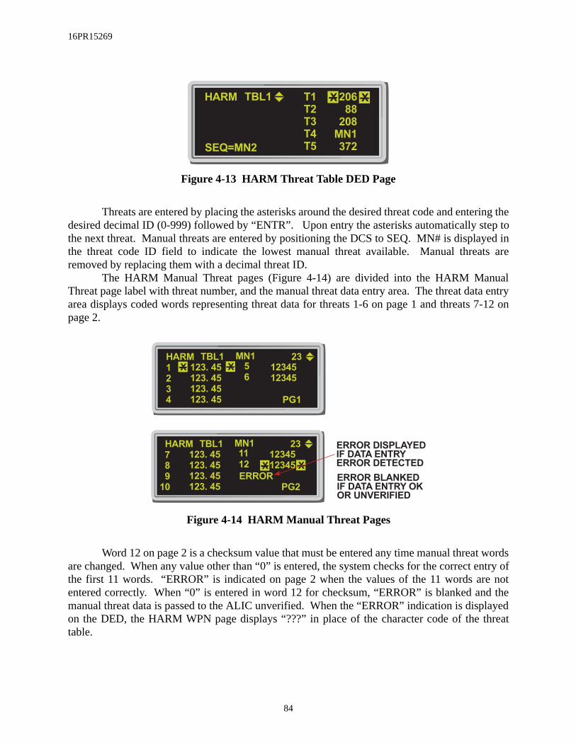
16PR15269
ep toyed ints are
ualta entry
7-12 on
t wordsentry ofre notd thelayedthreat
Figure 4-13 HARM Threat Table DED Page
Threats are entered by placing the asterisks around the desired threat code and entering thedesired decimal ID (0-999) followed by “ENTR”. Upon entry the asterisks automatically stthe next threat. Manual threats are entered by positioning the DCS to SEQ. MN# is displathe threat code ID field to indicate the lowest manual threat available. Manual threaremoved by replacing them with a decimal threat ID.
The HARM Manual Threat pages (Figure 4-14) are divided into the HARM ManThreat page label with threat number, and the manual threat data entry area. The threat daarea displays coded words representing threat data for threats 1-6 on page 1 and threatspage 2.
Figure 4-14 HARM Manual Threat Pages
Word 12 on page 2 is a checksum value that must be entered any time manual threaare changed. When any value other than “0” is entered, the system checks for the correct the first 11 words. “ERROR” is indicated on page 2 when the values of the 11 words aentered correctly. When “0” is entered in word 12 for checksum, “ERROR” is blanked anmanual threat data is passed to the ALIC unverified. When the “ERROR” indication is dispon the DED, the HARM WPN page displays “???” in place of the character code of the table.
HARM
372
208
88
TBL1
SEQ=MN2
MN1
T2
XX206
T5
T4
T3
T1
HARM
PG1
123. 45
TBL1 MN1
2
XX
23
5
4
3
1
6
123. 45
123. 45
123. 45
12345
12345
HARM
PG2
123. 45
TBL1 MN1
8 XX
23
11
10
9
7
12
123. 45
123. 45
123. 45
12345
12345
ERROR
ERROR DISPLAYED
IF DATA ENTRY
ERROR DETECTED
ERROR BLANKED
IF DATA ENTRY OK
OR UNVERIFIED
84

16PR15269
HARM Delivery Modes:The HARM missile can be delivered using any of three operational delivery modes:
1) Position Known (POS)2) Harm as a Sensor (HAS)3) Data Link (DL) - This mode only available with an IDM installed
When HARM is the selected weapon, the HARM operational mode is selected by depress-ing OSB #1 on the HARM Weapon page to access the Mode Menu page (Figure 4-15). From theMode Menu page select one of the following: POS (OSB #20), HAS (OSB #19), or DL (OSB#18) and return to the HARM Weapon page for that mode. Depressing cursor-Z also causes theHARM mode to change in the rotary sequence: POS, HAS, DL and back to POS, etc.
Figure 4-15 HARM Mode Menu Page
Position Known (POS) Mode:In the POS mode, the aircraft attitude and target position are passed to the HARM. After
launch the HARM flies to near the reported position of the target and then activates its seeker-head. The POS mode has the following flight profiles:
1) Equations of Motion (EOM): Provides threat specific off-axis capabilitywith a narrow FOV when the seekerhead is activated.
2) Range Unknown (RUK): Provides threat specific off-axis capability with awide FOV. Used when target range confidence is low. (Degraded state ofEOM).
GAIN SYM
BRT CON
SWAP WPN HSD S-J
POS
W
DL
NOT SOI
HAS
POS
85

16PR15269
3) Pre-Briefed (PB): Provides location specific, on-axis capability with awide FOV. PB is used for long range delivery with high confidence targetlocation.
The controls and display information on the HARM Base page (Figure 4-16) are listedbelow:
Controls:
1) HARM Mode (OSB #1): Access Mode Menu page to select HARM mode(POS, HAS, or DL), or step through modes with cursor-Z
2) Primary Selected Threat Table (OSB #2): Steps through the three threattables, or TMS left in POS or HAS
3) POS Flight Profiles (OSB #3): Steps through the three flight profiles(EOM, RUK, PB) or pinky switch on the sidestick in POS or DL
4) UFC Threat Table Access (OSB #5): Access selected HARM Threat Tableon DED
5) Geographic Specificity (GS) (OSB #9): “GS ON/GS OF” CommandsHARM to attack only a designated threat within a geographic regiondefined by a circle around the selected threat. It overrides the glide optionof target isolate (Block IIIA only, GS is blanked for other HARM versions)
6) Target Isolate (TI) (OSB #10): Commands HARM to attack only the des-ignated threat type and influences the approach by controlling the “flex”and “glide” missile characteristics. Uncage on the throttle also commandsTI
7) Selective Jettison (S-J) (OSB #11): Jettisons the HARM (weapon only) orHARM and LAU-118 (weapon and launcher)
8) Threat Selection/Deselection (OSB #s 16-20): Selects/Deselects the threatto be handed-off to the missile as target type. The threat symbol highlightswhile threat information is handed-off and accepted. TMS right selects thefirst valid threat, a second TMS right steps to the next valid target. TMSaft deselects the currently selected threat.
86

16PR15269
Figure 4-16 HARM POS WPN Delivery Page
Display Information:
Detected Threat Status Box (DTSB) is just below the top line of text and contains thethreat that is handed-off, when detected by the missile. When deselected, the threat is blankedfrom the DTSB.
The center of the HARM WPN page contains missile employment information. It isdivided into two sections by a Launch Status Divider Line (LSDL). Pre-launch information is dis-played below the LSDL and directly above the selected missile station. Pre-launch informationincludes: the selected threat type, the selected threat position (steerpoint number), missile Time-of-Flight (TOF) in mm:ss format, Time-on-Target (TOT) in hh:mm:ss 24 hour format (TOT is notdisplayed in RUK mode), and HARM loaded stations (selected station is highlighted). The abovedata is displayed from top down.
Post-launch information is displayed above the LSDL in reverse order (bottom to top).Post launch includes: the threat type attacked, the threat location, and Time-Until-Impact (TUI).The TUI is displayed for five seconds after reaching zero (0:00) (TUI is not displayed in RUKmode). Post-launch data is retained and displayed until power is cycled or inventory is changed.
HUD symbology for HARM POS launches (Figure 4-17) is similar to symbology in theContinuously Computed Release Point (CCRP) delivery mode. Although HARM can beemployed from a variety of delivery angles, loft is the preferred maneuver, therefore, the HUDdisplay has been optimized for Loft deliveries.
The following HUD symbology is displayed in all HARM POS flight profiles unlessstated otherwise:
GAIN SYM
BRT CON
SWAP WPN HSD S-J
POS
3
UFC
W
10
GS
OF
22
RDY
TBL1
0 : 52
T
I
4
10
RUK
MN1
12
6
6
6
1 : 40
23
14 : 55 : 31
87

16PR15269
1) Loft Solution Cues: Three loft solution cues are positioned on the AzimuthSteering Line (ASL). The large cue indicates the maximum aircraft climbangle at which the missile can make the required pull-down. The middlesolution cue (> <)(PB only) indicates the optimal aircraft climb angle. Thesmall solution cue indicates the minimum aircraft climb angle at which themissile can make the required pull-up. The solution cues are blanked fromthe ASL until reaching the maximum aircraft maneuver zone range (withinthe HLS). The Loft solution cue is not available in the RUK mode.
2) HARM Launch Scale (HLS): The HLS is displayed on the right side of theHUD.
3) Predicted Release Altitude: The predicted release altitude (AGL) abovethe target is at the bottom of the HLS (in hundreds of feet) shows where theaircraft will be if the pilot pulls up to the loft angle indicated next to the in-range cue (based on 4-G pull-up). Not available in the RUK mode.
4) Required Turn: The required turn angle to achieve missile launch condi-tions is displayed below the predicted release altitude. It represents theangle (0-99 degrees) left or right (L##, R##) required to bring the aircraftwithin the Missile Maneuver Zone (MMZ). Not available in the RUK andPB modes. When within the MMZ, it represents the angle to bring the tar-get on the nose.
5) Time-To-Release (TTR): The TTR is displayed above the bearing andrange to the target. TTR indicates the time to reach the edge of the launchenvelope under current flight conditions. Once within the missile maneu-ver zone the TTR indicates zero.
6) Mode Display: HARM is displayed below the airspeed scale. HRMVIP isdisplayed when VIP is selected and HRMVRP is displayed when VRP isselected.
7) HARM FOV Box: A HARM unique box indicating in-range launch enableand the end game FOV is displayed in the lower half of the HUD. The boxis 1.5 degrees tall and 4 degrees wide for the EOM submode and 8 degreeswide for the RUK and PB submodes. The box flashes when the HLS rangecue is in the missile maneuver zone and has accepted the hand-off data.
88
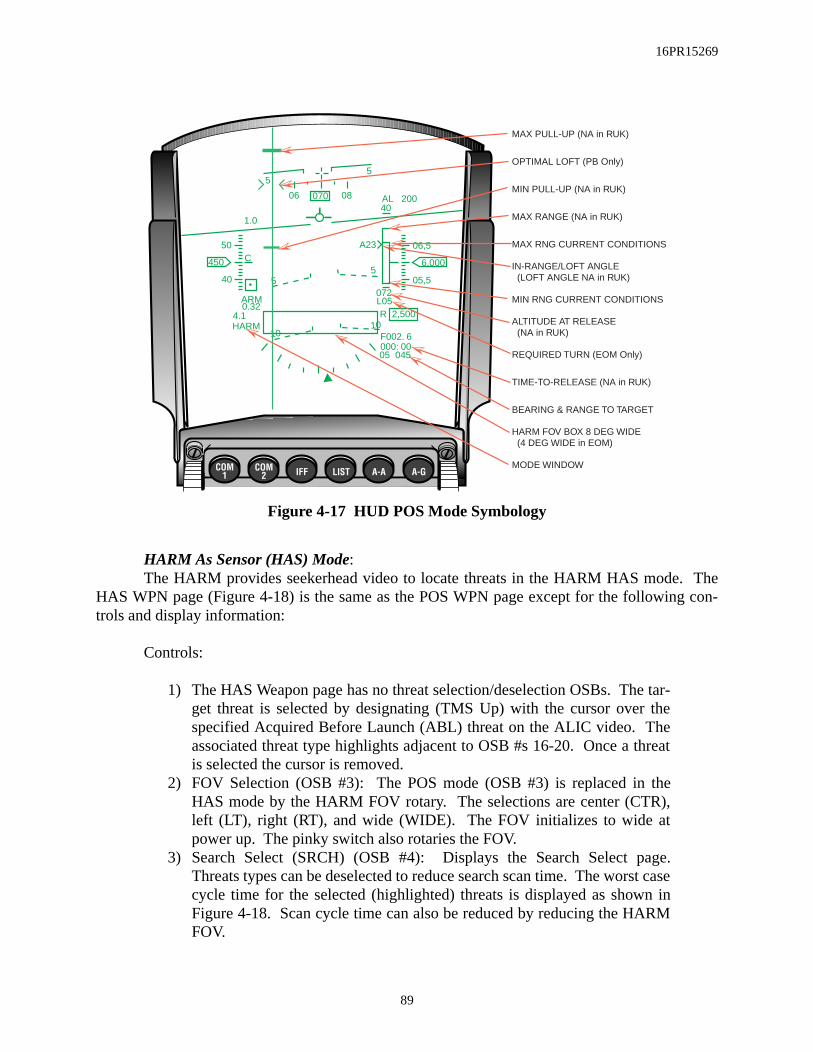
16PR15269
Figure 4-17 HUD POS Mode Symbology
HARM As Sensor (HAS) Mode: The HARM provides seekerhead video to locate threats in the HARM HAS mode. The
HAS WPN page (Figure 4-18) is the same as the POS WPN page except for the following con-trols and display information:
Controls:
1) The HAS Weapon page has no threat selection/deselection OSBs. The tar-get threat is selected by designating (TMS Up) with the cursor over thespecified Acquired Before Launch (ABL) threat on the ALIC video. Theassociated threat type highlights adjacent to OSB #s 16-20. Once a threatis selected the cursor is removed.
2) FOV Selection (OSB #3): The POS mode (OSB #3) is replaced in theHAS mode by the HARM FOV rotary. The selections are center (CTR),left (LT), right (RT), and wide (WIDE). The FOV initializes to wide atpower up. The pinky switch also rotaries the FOV.
3) Search Select (SRCH) (OSB #4): Displays the Search Select page.Threats types can be deselected to reduce search scan time. The worst casecycle time for the selected (highlighted) threats is displayed as shown inFigure 4-18. Scan cycle time can also be reduced by reducing the HARMFOV.
06 08070
6,000450
55
5 5
50
40
06,5
05,5
1.0
C
0.324.1HARM
R 2,500
AL 200
F002. 6
05 045000: 00
10 10
ARM
REQUIRED TURN (EOM Only)
MAX PULL-UP (NA in RUK)
OPTIMAL LOFT (PB Only)
MIN PULL-UP (NA in RUK)
MAX RANGE (NA in RUK)
MAX RNG CURRENT CONDITIONS
IN-RANGE/LOFT ANGLE (LOFT ANGLE NA in RUK)
MIN RNG CURRENT CONDITIONS
ALTITUDE AT RELEASE (NA in RUK)
L05072
40
A23
TIME-TO-RELEASE (NA in RUK)
BEARING & RANGE TO TARGET
HARM FOV BOX 8 DEG WIDE (4 DEG WIDE in EOM)
MODE WINDOW
89

16PR15269
is dis-
4) Restart (RS) (OSB #7): Restarts the scan cycle and blanks all previouslydisplayed threats on the Search Select page.
Figure 4-18 ALIC Video Display Before Hand-Off
Display information:
The Detected Threat Status Box (DTSB), near the top of the MFD contains the threattypes detected by the HARM seekerhead. Detected threats are displayed left to right. After athreat hand-off, the detected threats remain displayed. Threats are blanked from the DTSB whenno longer detected.
ALIC provided video of detected threats is displayed in the center of the HAS WPN page.The ALIC provides two video displays: 1) used for searching, and 2) used after hand-off. The ini-tial video display before hand-off is shown in figure 4-18 above. Two threats can be displayed foreach threat table entry, for a total of ten threats. If two threats are not detected for each threattable entry, more than two threats may be shown for the other table entries. The detected threatsare displayed on the relative azimuth and elevation from the nose of the missile. When detected,the threats are displayed with an identification letter representing the radar type. If multiple radartypes are detected for the same threat type at the same location, the identification letter is not dis-played with the threat type number. Only the highest priority threat is displayed when multiplethreat types are detected at the same location. Detected threats are stationary with respect to theground as the aircraft rolls and pitches. Threats are displayed on the bottom line of the videowhen they go below the seekerhead FOV.
After a threat is handed-off to the HARM, the display (Figure 4-19) represents the missileboresight and the threat video responds to aircraft pitch, roll, and azimuth changes. “RDY”
GAIN SYM
BRT CON
SWAP WPN HSD S-J
HAS
3
UFC
W
10
R
S
SCT-1
TBL1
0 : 52
T
I
4
6A
WIDE
MN1
12
6
4T
4 10
SRCH
7
D
6
10A
10T
10
4T
WORST CASE/
SCAN CYCLE TIME
RESTART HAS
SEARCH CYCLE
HAS CURSOR
ALIC VIDEO
DISPLAY AREA
DETECTED THREAT
STATUS BOX
90

16PR15269
ode
ndi-
nge to
played after the hand-off is complete. If the threat leaves the HARM FOV for more than 10 sec-onds, the hand-off is dropped, the ALIC returns to the search mode, and the display reverts backto the before hand-off format. If track is lost after the hand-off, the highlighted threat will flash.The designated threat is highlighted along with the threat type OSB label. The other detectedthreat types are blanked from the display.
Figure 4-19 ALIC Video Display After Hand-Off
When the TMS right is depressed, the threat sub-types for the handed-off threat are
stepped through and sent to the ALIC to perform a check to see if the threat is still radiating. Thischeck is known as the Acquire Before Launch (ABL) confirmation. If the threat passes the ABLconfirmation, the ALIC will preform another hand-off the data. While this second hand-off isoccuring, “RDY” is dropped until the new hand-off is complete.
In the HAS mode, the HUD symbology (Figure 4-20) is similar to the NAV master mwith the following exceptions:
1) Mode Display: HARM, or HRMVIP is displayed below the airspeed scale to icate aircraft mode of HARM, or VIP. VRP is not available in HAS.
2) HARM FOV Box: HARM FOV box is displayed the same as in POS/EOM.3) VIP Selected: Range and steerpoint number is replaced by bearing and ra
target.
GAIN SYM
BRT CON
SWAP WPN HSD S-J
HAS
3
UFC
W RDY
TBL1
T
I
4
WIDE
MN1
12
10
7
D
6
10A
10T
10
10
NOT SOI
91

16PR15269
es-ed andFDs.
fol-
Figure 4-20 HARM HAS Mode HUD Symbology
HARM Data Link (DL) Mode:The DL operational mode is available when the Improved Data Modem (IDM) is installed
in the aircraft. The IDM can receive Suppression of Enemy Air Defense (SEAD) messages andprovides the information to the HARM for targeting.
To receive SEAD messages via the IDM, the IDM communication protocol (A-G DLpage) must be AFAPD. When the avionics system receives a SEAD message, the following indi-cations are provided:
1) Distinct tones (dependent on the data rate) can be heard in the headset.2) The mnemonic “SEADxx DATA” is displayed centered on the HUD.3) A VMU message “DATA” is provided in the headset.
The “xx” in the HUD mnemonic indicates the steerpoint number in which the SEAD msage is stored. The HUD mnemonic remains displayed until either Warn Reset is depressreleased, the DED DL SEAD page is displayed, or the HARM DL page is displayed on the M
When the FILL option is “ALL”, the system stores received SEAD messages in thelowing priority scheme:
1) If the system contains a SEAD message (in steerpoints 71-80) with thesame message ID as the received SEAD message, that storage location isoverwritten;
06 08070
6,000450
55
5 5
50
40
06,5
05,5
1.0
C
0.324.1HARM
R 2,500
AL 200
F002. 6
003>23001. 06
10 10
ARM
STEERPOINT DIAMOND
TIME TO STEERPOINT
RANGE & STEERPOINT
HARM FOV BOX
MODE WINDOW
92

16PR15269
2) When no stored SEAD message has the same ID, the system stores themessage in the first empty steerpoint (71-80) in increasing sequentialorder;
3) Lastly, if an empty steerpoint location is not available, the system storesthe message in the location containing the oldest data link message, notselected for hand-off to the HARM missile
When the received data link message is a CAS Mission Update message containing bothan IP and a TGT, the system stores the 2 locations in 2 contiguous steerpoints using a similar stor-age scheme:
1) If there is at least one empty pair of contiguous steerpoints (71-80), thesystem stores the IP and TGT locations in that steerpoint pair, sequentially(IP then TGT), in increasing steerpoint number and wrapping from 80 to71;
2) Otherwise, if there is only one empty steerpoint, the IP is stored in theopen steerpoint and the TGT is stored in the next increasing steerpointlocation, wrapping from 80 to 71; the TGT position overwrites the datastored in that location;
3) Lastly, if an empty steerpoint location is not available, the system storesthe IP in the location containing the oldest data link message, and the TGTis stored in the next increasing steerpoint location, wrapping from 80 to71.
In the case where the CAS TGT overwrites a previous data link CAS IP, the TGT associated withthe overwritten IP is also deleted from the system.
When the selected FILL option is NONE, the received SEAD message is discarded and noHUD or VMU advisories are provided. The system can store up to 127 SEAD messages on theDTE for post-flight data analysis (regardless of the FILL option).
SEAD Message Display (DED & HSD)Received SEAD target locations are displayed on the SEAD Destination and Steerpoint
pages (Figures 4-21&22). When the entered steerpoint (71-80) on any destination page containsSEAD data, the SEAD Destination page is displayed. The display includes steerpoint number,target latitude, longitude, elevation, and time-on-target.
Figure 4-21 DED SEAD Destination Page
SEAD
26: 15: 00
ELEV
LNG
LAT
TOS
512FT
45 12 . 756'N
56 34 . 382'W
XX 71
93

16PR15269
he3). ThetronicSEAD
The STPT page displays data for steerpoints 1-99. The data includes steerpoint numberand sequencing mode, latitude, longitude, elevation, and time-over-steerpoint (Figure 4-22).
Figure 4-22 DED Steerpoint Page
A-G data link (GDLNK) symbology must be selected on the HSD Control page (OSB#17) to display the SEAD target position on the HSD. When a SEAD target is received, the targetposition is displayed on the HSD by mippling “DL” and the SEAD threat character code. TSEAD threat character code is an alpha-numeric code of up to 3 characters (Figure 4-2MFDs uses a Threat Symbology Table (TST), loaded from the DTE along with the ElecIntelligence (ELINT) file, to determine the character code associated with the threat. The character code determination is summarized below.
1) The HSD displays the character code associated with the threat based onthe TST.
2) “MN” is displayed for a manual threat. A valid manual threat is a threatthat has been located but may not be currently defined by the TST.
3) “???” is displayed if the SEAD target is not found in the TST.4) If the TST has not been loaded, the threat index number is displayed at the
target location. The threat index number is a numeric sequence numberthat correlates to a character code to be displayed on the HSD.
STPT
26: 15: 00
ELEV
LNG
LAT
TOS
512FT
45 12 . 756'N
56 34 . 382'W
XX 71 MAN
94

16PR15269
Figure 4-23 HSD SEAD Target Display
Depressing Warn Reset or selecting the mippling SEAD target as the DL TOI, stops mip-pling the SEAD characters and displays the character code over a slash (Figure 4-24) at the targetposition. There is no indication of a data link SEAD target position outside the HSD FOV untilthe SEAD target is selected as a DL TOI.
Figure 4-24 Data Link SEAD Character Code Display
SEAD Message Selection (Data Link Target of Interest (DL TOI))A data link SEAD threat displayed on the HSD can be selected as the Data Link Target
Of Interest (DL TOI) when the HSD is the selected SOI. There can be only one DL TOI. A datalink CAS IP or CAS TGT can also be selected as a DL TOI on the HSD.
A box is displayed about the SEAD threat selected as the DL TOI. The avionics systemprovides a hands-on method of selecting a received SEAD target as the DL-TOI, displaying theDL-TOI on the DED DL SEAD page, and stepping among the received data link SEAD targets.The following summarizes the available hands-on operations using the TMS switch:
GAIN SYM
BRT CON
SWAPSMS DTE S-J
60
F
Z
HSD
DCPL CNTLDEP
35210
3
20
NORM
12
DL SEAD
MESSAGE(HIGHLIGHTED)
DL SEAD
MESSAGE(BOXED)
8
12 1212DL DL
12
WARN RESET OR
BOXED SEAD
MIPPLE
95

16PR15269
1) TMS Up (Designate): Selects the SEAD target as a DL TOI and displays abox about the symbol.
2) TMS Left: Displays the DED DL page for the DL TOI (Figure 4-25). Ifthe DL TOI is a SEAD target the DED DL SEAD page is displayed.
3) TMS Right (no DL TOI): Selects the received data link SEAD message asthe DL TOI. If the last received data link message was a SEAD message;a box is displayed about the SEAD target. If the target is outside the HSDFOV, the HSD automatically increases the range scale to a range sufficientto display the SEAD target position (up to 120 NM for depressed and 80NM for the centered format). If the target position is still outside the FOV,the system displays a Data Link Target Outside FOV symbol (filled trian-gle), pointed outward along the outermost range ring at the bearing of theDL SEAD position. If the range rings are turned off, the filled triangle isdisplayed along the perimeter of the MFD at the bearing of the DL SEADposition.
4) TMS Right (with a DL TOI): a) When a SEAD target is the DL TOI, TMS right steps the box to the
next SEAD target in increasing display distance from the bottomof the HSD, and from right to left. When the farthest SEAD targetis the DL TOI, TMS right wraps the TOI box back to the closestSEAD target on the HSD display. (NOTE: the stepping function onthe HSD is always from a SEAD to SEAD or a CAS to CAS target).If the SEAD target being stepped to is outside of the FOV, therange scale is automatically increased.
b) When a DL TOI exists and it’s not the last received data link tar-get, TMS right for greater than 1 second selects the last receiveddata link target as a DL TOI, whether the last received is a DLCAS IP, DL CAS TGT, or a DL SEAD. If the SEAD target beingstepped to is outside of the FOV, the range scale is automaticallyincreased.
5) TMS Aft:a) TMS Aft <= 1 sec: Drops the DL TOI (box) and displays the
CNI page if a DL SEAD page was displayed, regardless ofHSD cursor position.
b) TMS Aft > 1 sec: Commands the zeroize message when aSEAD target is the DL TOI with the HSD cursor correlatedwith the SEAD target.
96

16PR15269
Figure 4-25 SEAD DL Page
When the DED DL SEAD page is displayed, INC/DEC or entering a DL SEAD STPTnumber (71-80) steps the DL STPT up or down to the selected DL SEAD message. When the DLSTPT is changed, the SEAD box (TOI) on the HSD steps to the new SEAD target associated withthe new DL STPT and the data on the DL SEAD page reflects the selected DL SEAD TOI. If aSTPT (71-80) does not contain a DL SEAD target, that STPT is skipped. Hands-on selection of anew DL SEAD TOI (TMS right or Designate) updates the DL SEAD page with the new SEADDL TOI data.
SEAD Message TransmissionWhen a DL SEAD target is selected as the DL TOI on the HSD, the SEAD target position
and its characteristics can be transmitted to another properly equipped aircraft. The procedure fortransmitting a DL SEAD message follows:
1) Enter the transmit address (XMT) on the A-G DL initialization page forthe intended receiver (Figure 4-26).
2) Ensure the radio (COMM) and data rate (DATA) match the intendedreceiver. These selections must match for any DL communication.
3) Ensure the protocol (PRTL) is AFAPD. SEAD messages require theAFAPD protocol.
4) Place the SOI on the HSD, select the desired SEAD target as a DL TOI,and depress COMM Inboard on the throttle;a) verify “XMT” highlights temporarily (OSB #6 on the HSD).b) verify the A-G DL radio (UHF/VHF) highlights on the DED
CNI page during DL transmission.c) verify that a tone is heard in the headset for data rate 1200.
To receive DL SEAD messages ensure the:
1) Radio (COMM) and data rate (DATA) match the transmitter 2) Protocol (PRTL) is AFAPD.3) Fill option (FILL) is ALL.
SEAD
26: 15: 00
ELV
B/R
TGT
TOT
512FT
006
090 /03NM
XX 71
T IH IGH
I DDL AA
DL STPT MESSAGE IDENTIFIER
TARGETISOLATE
RANGECONFIDENCE
TARGET TYPE(THREAT ID)
TARGETBEARING/RANGE
TARGETELEVATION
TIME-ON-TARGET
97
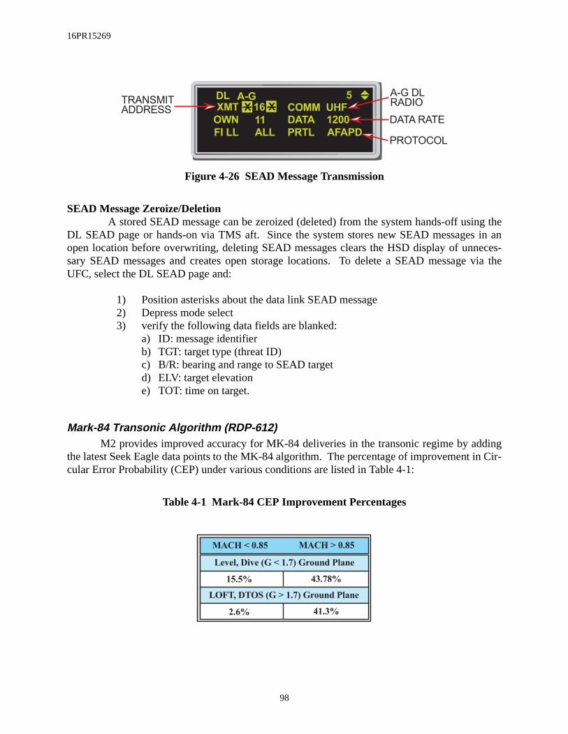
16PR15269
Figure 4-26 SEAD Message Transmission
SEAD Message Zeroize/DeletionA stored SEAD message can be zeroized (deleted) from the system hands-off using the
DL SEAD page or hands-on via TMS aft. Since the system stores new SEAD messages in anopen location before overwriting, deleting SEAD messages clears the HSD display of unneces-sary SEAD messages and creates open storage locations. To delete a SEAD message via theUFC, select the DL SEAD page and:
1) Position asterisks about the data link SEAD message2) Depress mode select3) verify the following data fields are blanked:
a) ID: message identifier b) TGT: target type (threat ID)c) B/R: bearing and range to SEAD targetd) ELV: target elevatione) TOT: time on target.
Mark-84 Transonic Algorithm (RDP-612)M2 provides improved accuracy for MK-84 deliveries in the transonic regime by adding
the latest Seek Eagle data points to the MK-84 algorithm. The percentage of improvement in Cir-cular Error Probability (CEP) under various conditions are listed in Table 4-1:
Table 4-1 Mark-84 CEP Improvement Percentages
A-G
FI LL
OWN
XMT
ALL
16 XX
5
UHFCOMM
DLTRANSMIT
ADDRESS
A-G DL
RADIO
PROTOCOLPRTL
DATA 1200
AFAPD
11 DATA RATE
MACH < 0.85 MACH > 0.85
Level, Dive (G < 1.7) Ground Plane
15.5% 43.78%
LOFT, DTOS (G > 1.7) Ground Plane
2.6% 41.3%
98

16PR15269
Update CBU-87 Algorithm (RDP-625)The CBU-87 algorithm was changed to account for a known proximity fuze bias and to
update separation effects coefficients. The percentage improvement in CBU-87 CEP for variousdeliveries and rack ID’s are shown in Table 4-2:
Table 4-2 CBU-87 CEP Improvement Percentages
RACK ID ATRK BIAS CEP
G-LOADED DELIVERIES
1-G DELIVERIES
ALL DELIVERIES
12 (MAU)
20 (TER)
12 (MAU)
20 (TER)
12 (MAU)
20 (TER)
88.3%
100.4%
149.7%
105.6%
96.7%
99.1%
19.6%
16.3%
10.1%
10.1%
19.0%
14.7%
99

16PR15269
THIS PAGE INTENTIALLY LEFT BLANK
100

16PR15269
ringsre onlynd
(Figureursor threat A dou- ranget steer-on and
in the
SECTION 5 - DEFENSIVE AVIONICSThis section introduces the folowing Defensive Avionics enhancements:
• Selectable Threat Range Rings On The HSD• Report Jamming Of AIFF Frequencies
Selectable Threat Range Rings On The HSD (RDP-967)This change provides for hands-on declutter of individual preplanned threat range
and the ability to make a preplanned threat the current steerpoint. Threat range rings aavailable for preplanned threats when PRE (OSB #2) is selected on the HSD Control page, aall threat range rings are displayed by default. Placing the cursor over a preplanned threat5-1) and TMS aft will declutter the threat range ring for that threat. TMS forward with the con a decluttered threat will display the threat’s range ring. TMS forward on a preplannedwith the threat range ring displayed selects the threat’s location as the current steerpoint. ble TMS forward is required to select a preplanned threat that is not displaying its threatring. TMS forward with the cursor over any steerpoint selects that steerpoint as the currenpoint. Individual preplanned threat range ring status is retained (last left) through deselectiselection of preplanned threats.
Figure 5-1 HSD Threat Ring Display
Report Jamming Of AIFF Frequencies (RDP-880)The AIFF jamming (IJAM) option selects the jamming indicators “I” and “IFF JAM” for
display on the FCR pages when noise is detected by the AIFF transponder. Entering 7
GAIN SYM
BRT CON
SWAP SMS DTE S-JHSD
PRE CNTLFCR
LINE3
LINE2
LINE1
ADLNK
GDLNK
NAV3
NAV2
NAV1
CRPCAI FF
RINGS
LINE4
SA6
5
W
101
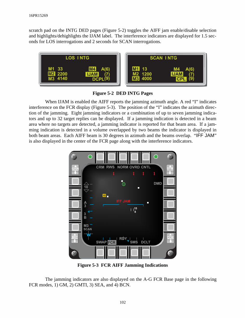
16PR15269
atesdirec-dica- beamf a jam-yed in
wing
scratch pad on the INTG DED pages (Figure 5-2) toggles the AIFF jam enable/disable selectionand highlights/dehighlights the IJAM label. The interference indicators are displayed for 1.5 sec-onds for LOS interrogations and 2 seconds for SCAN interrogations.
Figure 5-2 DED INTG Pages
When IJAM is enabled the AIFF reports the jamming azimuth angle. A red “I” indicinterference on the FCR display (Figure 5-3). The position of the “I” indicates the azimuth tion of the jamming. Eight jamming indicators or a combination of up to seven jamming intors and up to 32 target replies can be displayed. If a jamming indication is detected in aarea where no targets are detected, a jamming indicator is reported for that beam area. Iming indication is detected in a volume overlapped by two beams the indicator is displaboth beam areas. Each AIFF beam is 30 degrees in azimuth and the beams overlap. “IFF JAM”is also displayed in the center of the FCR page along with the interference indicators.
Figure 5-3 FCR AIFF Jamming Indications
The jamming indicators are also displayed on the A-G FCR Base page in the folloFCR modes, 1) GM, 2) GMTI, 3) SEA, and 4) BCN.
SCAN I NTG
4000120013
M3M2M1
(9)(7)
A(6)
CPLIJAMM4
LOS I NTG
4140220033
M3M2M1
(9)(7)
A(6)
DCPLIJAM
M4
GAIN SYM
BRT CON
SWAP DCLT
10
FCR
CRM CNTLOVRD
DMD
A
3
W
RDY
SMS
NORMRWS
3
B
M3
3
I I I I
IFF JAM
3
15
8
SCAN
102
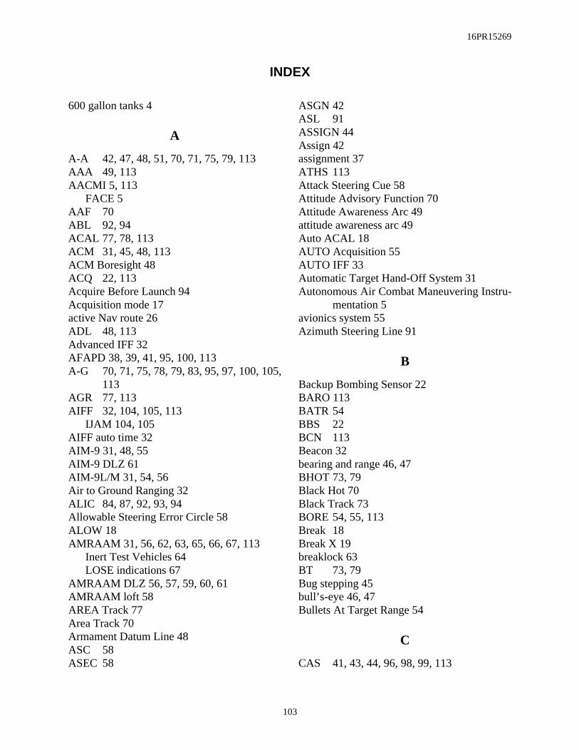
16PR15269
INDEX
600 gallon tanks 4
A
A-A 42, 47, 48, 51, 70, 71, 75, 79, 113AAA 49, 113AACMI 5, 113
FACE 5AAF 70ABL 92, 94ACAL 77, 78, 113ACM 31, 45, 48, 113ACM Boresight 48ACQ 22, 113Acquire Before Launch 94Acquisition mode 17active Nav route 26ADL 48, 113Advanced IFF 32AFAPD 38, 39, 41, 95, 100, 113A-G 70, 71, 75, 78, 79, 83, 95, 97, 100, 105,
113AGR 77, 113AIFF 32, 104, 105, 113
IJAM 104, 105AIFF auto time 32AIM-9 31, 48, 55AIM-9 DLZ 61AIM-9L/M 31, 54, 56Air to Ground Ranging 32ALIC 84, 87, 92, 93, 94Allowable Steering Error Circle 58ALOW 18AMRAAM 31, 56, 62, 63, 65, 66, 67, 113
Inert Test Vehicles 64LOSE indications 67
AMRAAM DLZ 56, 57, 59, 60, 61AMRAAM loft 58AREA Track 77Area Track 70Armament Datum Line 48ASC 58ASEC 58
ASGN 42ASL 91ASSIGN 44Assign 42assignment 37ATHS 113Attack Steering Cue 58Attitude Advisory Function 70Attitude Awareness Arc 49attitude awareness arc 49Auto ACAL 18AUTO Acquisition 55AUTO IFF 33Automatic Target Hand-Off System 31Autonomous Air Combat Maneuvering Instru-
mentation 5avionics system 55Azimuth Steering Line 91
B
Backup Bombing Sensor 22BARO 113BATR 54BBS 22BCN 113Beacon 32bearing and range 46, 47BHOT 73, 79Black Hot 70Black Track 73BORE 54, 55, 113Break 18Break X 19breaklock 63BT 73, 79Bug stepping 45bull’s-eye 46, 47Bullets At Target Range 54
C
CAS 41, 43, 44, 96, 98, 99, 113
103

16PR15269
CAS message 39CBU-87 70, 102CCRP 90CEP 101, 102Circular Error Probability 101Close Air Support 37CMFD 6, 113
color palette 6C-Mux bus 5CNI 4CNI page 99, 100Coast 51Color Multi-Function Display 6color palette
primary additive colors 6primary subtractive colors 6symbol color, default colors 6
COMM 2 4Computed Rates 77CONT 42Continuous 31couple 32Cruise Time 28CRUS TOS 29, 30
D
D/L 8, 114Data Base Terrain Cueing 15Data Link 8, 31, 99Data link 37, 43Data Link Steerpoints 31Data Rate 38Data Transfer Cartridge Loader/Reader 6Data Transfer Equipment 25DBTC 18, 19, 20, 21, 23, 114DBTC cue 23DCS 86decouple 32DED 6, 13, 16, 27, 28, 29, 30, 42, 52, 95, 96,
97, 98, 99, 100, 105, 114AIFF Time (TIM) page 32CRUS TOS page 13Laser page 27Time page 13
default colors 6
DEMAND 37Detected Threat Status Box 90DFM 17, 19, 22, 23DGFT 31, 49, 114Digital Flight Map 17Digital Terrain System 15Digital Terrain System Application Software
20DL 42, 43, 88, 95, 97, 98, 99, 100, 101, 114DL SEAD 44DL TOI 32DLZ 48, 64, 65, 66, 67, 83, 114DMD 114DTC 6, 29, 114
L/R 6DTE 25, 27
load 27DTED 23DTS 15, 16, 17, 18, 20, 21, 22, 23, 114DTS/DTC 22DTSACQ 16, 17DTSB 90, 93DTSFIX 16
E
EACMI 5EEGS 31, 53, 54, 114Electronic expansion 70Electro-Optic 83ELINT 97E-O 83EOM 88, 94Equations of Motion 88EWMS 81
F
FAC 114Fatigue/Air Combat Evaluator 5FCR 4, 10, 12, 32, 42, 45, 46, 48, 51, 55, 66,
73, 79, 104, 105, 114cursor minimum search altitude display 46
FCR EXPAND 47FEDS 31, 53, 54Field Of View 8
104

16PR15269
Filter Mode 16Firing Evaluation Display System 53Fixed Target Track 32flight path marker 21FLIR 26, 70
Base page 26Forward Looking Infrared 70Friendly 12FTT 32, 114
G
GDLNK 97, 115GHL 49, 50, 115Ghost Horizon Line 49GMTI 32GND PROX 18GPS 13, 15, 16, 18
time 13Ground Map 32Ground Moving Target Indicator 32
H
HARM 56, 70, 84, 85, 86, 88, 90, 92, 93, 95,96, 115
acquired before launch 92Aircraft Launcher Interface Computer 84ALIC 84Command Destruct 85DL 88, 95Gyro Test 85HAS 88, 92HTV 84Launch scale 91POS 88, 90
Equations of Motion 88Geographic Specificity 89Pre-briefed 89Range unknown 88Target isolate 89
Tertiary Table 85threat code ID 87Threat table 86
HARM Launch Scale 91
HARM Threat Table 86HAS 88, 94HAT 81, 83, 115Height Above Target 22Height-Above-Target 81High Speed Anti-Radiation Missile 84HLS 91horizon line 9Horizontal and Vertical Confidence 15Horizontal Range Known 22Horizontal Situation Display 8HSD 4, 8, 12, 15, 23, 24, 25, 32, 39, 42, 43,
44, 96, 97, 98, 99, 100, 101, 104, 115Control page 25control page 25displays 12FOV 8Freeze 23, 25
HSD Declutter 15HSD Freeze 15HTV 84, 85HUD 15, 17, 18, 19, 21, 27, 28, 29, 30, 32, 46,
47, 48, 49, 51, 52, 54, 55, 56, 58, 59, 60,61, 66, 67, 77, 78, 79, 82, 83, 84, 90, 94,95, 96, 115
Total Field Of View 49HUD Symbology
Landing Phase 15
I
IDL 115IDM 31, 95, 115
Zeroize 31IDM Data Link 32IFF 104, 105, 113, 115IJAM 32ILS 28Improved Data Modem 42In-Flight Alignment 16Infrared 70INS 16, 18, 30, 79, 81, 83, 115interrogator codes 33interrogator modes 33IR 70
105
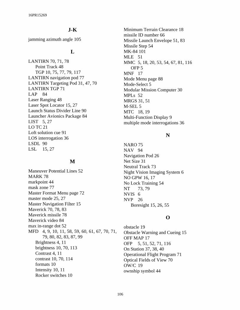
16PR15269
J-K
jamming azimuth angle 105
L
LANTIRN 70, 71, 78Point Track 48TGP 10, 75, 77, 79, 117
LANTIRN navigation pod 77LANTIRN Targeting Pod 31, 47, 70LANTIRN TGP 71LAP 84Laser Ranging 48Laser Spot Locator 15, 27Launch Status Divider Line 90Launcher Avionics Package 84LIST 5, 27LO TC 21Loft solution cue 91LOS interrogation 36LSDL 90LSL 15, 27
M
Maneuver Potential Lines 52MARK 78markpoint 44mask zone 77Master Format Menu page 72master mode 25, 27Master Navigation Filter 15Maverick 70, 78, 83Maverick missile 78Maverick video 84max in-range dot 52MFD 4, 9, 10, 11, 58, 59, 60, 61, 67, 70, 71,
79, 80, 82, 83, 87, 99Brightness 4, 11brightness 10, 70, 113Contrast 4, 11contrast 10, 70, 114formats 10Intensity 10, 11Rocker switches 10
Minimum Terrain Clearance 18missile ID number 66Missile Launch Envelope 51, 83Missile Step 54MK-84 101MLE 51MMC 5, 18, 20, 53, 54, 67, 81, 116
OFP 5MNF 17Mode Menu page 88Mode-Select 5Modular Mission Computer 30MPLs 52MRGS 31, 51M-SEL 5MTC 18, 19Multi-Function Display 9multiple mode interrogations 36
N
NARO 75NAV 94Navigation Pod 26Net Size 31Neutral Track 73Night Vision Imaging System 6NO GPW 16, 17No Lock Training 54NT 73, 79NVIS 6NVP 26
Boresight 15, 26, 55
O
obstacle 19Obstacle Warning and Cueing 15OFF MAP 17OFP 5, 51, 52, 71, 116On Station 37, 38, 40Operational Flight Program 71Optical Fields of View 70OW/C 19ownship symbol 44
106

16PR15269
P-Q
Passive Ranging 15, 22PB 89Penguin 78, 116penguin use rotary 78PGCAS 16, 17, 18, 19, 116
MTC 116PGU-28 52, 82Pilot Vehicle Interface 3POINT Track 76POINT track 77Point Track 70POS 33, 34, 88, 90, 92, 94PR 22Predictive Ground Collision Avoidance Sys-
tem 15preplanned delivery 78protocol 38, 100
R
RALT 116RECCE 70, 80, 81, 116RECCE Base page 80roll stabilized 23RUK 88, 90
S
SCAN interrogation 36Sea 32SEAD 31, 43, 44, 85, 95, 96, 97, 98, 99, 100,
101, 117SEAD DL 43Search Select 92Selective Jettison 89Situation Awareness Indicator 74SLAVE 54, 55SMS inventory 56SMT 31, 45Snowplow 73SOI 23, 24, 25, 48, 55, 70, 84, 98, 100, 117STPT 39Strafe pipper 82strafe pipper 82
system time 13system track targets 12
T
TACFIRE 38, 41, 117tail flash 64tail symbol 62Target Designator 48Target Locator Line 48, 51, 78Target Management Switch 32Target Of Interest 8, 67Targeting Pod 32, 70TCH 18, 20, 21, 117TD 51Team Address 43Team Member 43team member 44Terrain Clearance Height 18Terrain Reference Navigation 15TFOV 49, 117TGP 32, 47, 48, 55, 70, 71, 72, 73, 74, 75, 76,
77, 78, 79Display Polarity 73Gray Scale 73Sighting Point 73Snowplow 73Tracking Polarity 73
TGP LOS 48The TGP 70threat range rings 104threat symbology table 97TIM 33Time-Over-Steerpoint 15TLL 48, 51, 78, 79, 117TMS 32TOF 90TOI 8, 42, 43, 67, 98, 99, 100TOS 30TOT 90track 55, 75Transmit Address 38TRN 15, 17TST 97TUI 90TV 3, 79
107

16PR15269
U
UFC 5, 27, 29, 32, 37Universal Transverse Mecator 30Unknown 12Up-Front Controls 5UTM 15, 30
V
Vertical Velocity Propagator 18VHF radio 4
8.33 kHz 4FM frequency 5
visual delivery 78VMU 95, 96
W-X-Y-Z
Whiskers 23whiskers 21White Hot 70White Track 73WHOT 73, 79WIDE 75WT 73, 79
108

16PR15269
ABBREVIATIONS & ACRONYMS
A
A-A air-to-airA-G air-to-groundA/S airspeedAAA attitude awareness arcAACMI autonomous ACMIAAF attitude advisory functionAAM air-to-air missileABL acquired before launchABRT abortACAL altitude calibrationACCUR accuracyACM air combat modeACMI air combat maneuvering instru-
mentationACQ acquisitionADL armament datum lineADLNK A-A datalinkAFAPD Air Force applications develop-
mentAGC automatic gain/level controlAGL above ground levelAGR air-to-ground rangingAIFF advanced IFFAIM airborne intercept missileAL altitude lowALIC aircraft launcher interface com-
puterALOW altitude lowALT altitudeAM amplitude modulationAMMO ammunitionAMRAAM advanced medium range air-to-
air missileASC attack steering cueASEC allowable steering error circleASG/ASGN assignASL azimuth steering lineATHS automatic target hand-of systemATRK along trackAUD audio
AUTO automatic
B
B/R bearing and rangeBAF Belgium Air ForceBARO barometricBATR bullets at target rangeBBS backup bombing sensorBCN beaconBHOT black hotBIT built in testBORE boresightBP backupBPS bits per secondBRG bearingBRK breaklockBRT brightnessBSGT boresightBT black track
C
C correlationCADC Central Air Data ComputerCAS close air support/calibrated air-
speedCBU cluster bomb unitCCP configuration/contract change
proposalCCIP continuously comupted impact
pointCCRP continuously comupted release
pointCD command destructCDRL contract delivery requirements
listCEP circular error probabilityCLR clearCMFD color multifunction displayCNI communications,navigation, IFF
109

16PR15269
CNTL controlCOAS coastCOM/COMM communicationCON contrastCONT continuousCPL coupleCRM combined radar modeCRPC CARAPACECRUS cruiseCSI Carriage Store InterfaceCSSI Carriage Store Station InterfaceCTR centerCZ cursor zero
D
D&R depress and releaseD/L data linkDBTC database terrain cueingDCLT declutterDCPL decoupleDCS data control switchDEC decrementDED data entry displayDeg. degreesDEP depressedDESC descriptionDES/DEST destinationDFARS Department of Defense supple-
ment to the Federal AcquisitionRegulations
DFLT defaultDFM digital flight mapDGC display gain controlDGFT dogfightDIR directDL/DLNK data linkDLZ dynamic launch zoneDMD demandDoD Department of DefenseDTC data transfer cartridgeDTE data transfer equipmentDTED digital terrain elevation dataDTOS dive toss
DTS digital terrain systemDTS/DTC digital terrain system data trans-
fer cartridge DTSACQ DTS acquistionDTSAS digital terrain system application
softwareDTSB detected threat status boxDTU data transfer unit
E
E EastE/N Easting/NorthingEACMI enhanced ACMIECP engineering change proposalECU environmental control unitEEGS enhanced envelope gunsightELEV/ELV elevationELINT electronic intelligenceENTR enterE-O electro-opticalEOM equations of motionEPAF European Particapating Air
ForcesETA estimated time of arrivalEU Ejector UnitEXP expand
F
F fire control radarFAC forward air controllerFACE fatigue/air combat evaluatorFCR fire control radarFEDS firing evaluation display systemFLCS flight control systemFLIR forward looking infraredFM frequency modulationFOV field of viewFPM flight path markerFRND friendFT feetFT-L foot-lambertsFTT fixed target trackFZ freeze
110

16PR15269
G
G gravitational unit/gainGAAF ground avoidance advisory func-
tionGBU guided bomb unitGDLNK ground datalinkGEO geosynchronous earth orbitGHL ghost horizon lineGM ground mapGMTI ground moving target identifica-
tionGND groundGPS global positioning systemGPW ground proximity warningGS geographic specificityGT gyro test
H
H high/horizontalHARM highspeed anti-radiation missileHAS HARM as sensorHAT height above targetHB High BandwidthHDG headingHDPT hardpointHLS HARM launch scaleHR horizontal rangeHRM HARMHSD horizontal situation displayHTV HARM test vehicleHUD head up displayHz hertz
I
ICAO International Civil AviationOrganization
ICP integrated control panelID identificationIDL intraflight data linkIDM improved data modemIFA in-flight alignmentIFF identification friend or foeIJAM IFF jamming
ILS instrument landing systemIMNT imminentINC incrementINS inertial navigation systemINTG interrogationINV inventoryIP initial pointIR infraredITV integration test vehicle
J-K
KCAS knotts calibrated airspeedKHz kilo-hertz
L
L low / left / lambertsL/R loader/readerLADD low angle drogue deliveryLANTIRN low altitude navigation and tar-
geting infrared for nightLAP launcher avionics packageLASR laserLAT latitudeLAU launcherLB Low BandwidthLGB laser guided bombLM AERO Lockheed-Martin Aeronautics
CompanyLNG longitudeLO TC low terrain clearanceLOS line of sightLSDL launch status divider lineLSL laser spot locatorLT left
M
M medium / meterM-SEL mode selectMAL malfunctionMAN/MN manualMFD multi-function displayMGC manual gain/level controlMHz mega-hertz
111

16PR15269
MIN minutes/minimumMISC miscellaneousMKPT markpointMLE missile launch envelopeMLU mid-life updateMMC mission modular computerMMZ missile maneuver zoneMN manualMNF master navigation filterMPLS maneuver potential linesMPRF medium pulse rate frequencymr milli-radianMRGS multiple reference gunsightMRL missile rail launcherMRLW missile rail launcher with track
adapterMRM medium range missileMSL mean sea levelMSMD master modeMSN missionMTC minimum terrain clearanceMTI moving target indicesMUX multiplex
N
N NorthNA not applicable/not availableNARO narrowNAV navigationNM nautical mileNORM normalNT neutral trackNVIS night vision imaging systemNVP navigation pod
O
OA offset aim-pointOFP operational flight programOFST offsetOPER operationOSB option select buttonOVRD overrideOW/C obstacle warning and cueing
P
P/T position & timeP/PENG PenguinPB pre-briefedPFL pilot fault listPGCAS predictive ground clearance
avoidance systemPOS position knownPR passive rangingPRE preplannedPRF pulse rate frequencyPROF profilePROG programPROX proximityPRTL protocolPVI pilot vehicle interfacePWR power
Q-R
R radar altitude / rightRAERO kinematic rangeRMAX maximum rangeRMIN minimum rangeROPT optimum rangeRPI probable intercept rangeRTR turn and run maneuver rangeRAD radiateRADA the FACE system is referred to
as RADARALT radar altimeterRCD recordRDAF Royal Danish Air ForceRDP requirements development pack-
ageRDR radarRDY readyRECCE/RCCE reconnaissanceREQ requiredRF radio frequencyRMK remarksRNG rangeRNLAF Royal Netherlands Air Force
112

16PR15269
ROE rules of engagementRP release pointRS restartRST resetRSU rate sensor unitRT rightRTN returnRTS return to searchRUK range unknownRWS range while search
S
S-J selective jettisonSAI situation awareness indicatorSAM situation awareness modeSBC symbology/brightness/contrastSCOR scoreSEAD suppression of enemy air
defensesec secondSEQ sequenceSMS stores management systemSMT SAM multi-trackSOI sensor of interestSP snowplowSPAR system problem anomaly reportSPI system point of interestSRCH searchSRM short range missileSTA stationSTBY standbySTOR HDG stored headingSTP/STPT steerpointSTRF strafeSTT single target trackSYM symbologySYS system
T
T.O. technical orderTACFIRE/TACF tactical fire directionTBL tableTC terrain clearance
TCH terrain clearance heightTD target designatorTEMP temperatureTER tertiaryTFMAX maximum time of flightTFOV total field of viewTFR terrain following radarTGP targeting podTGT targetTHLD thresholdTI target isolateTIM timeTLL target locator lineTMS target management switchTNG trainingTOF time of flightTOI target of interestTOS time over steerpointTOT time-over-targetTRK trackTRN terrain referenced navigationTRP trapedTST threat symbology tableTTR time-to-releaseTTS two target SAMTUI time-until-impactTV televisionTWS track while scan
U
UFC up-front controlUHF ultra-high frequencyUNK unknownUSAF United States Air ForceUTM universal transverse mercator
V
V verticalVmax velocity (maximum)V/INST vehicle for instrumentationVHF very-high frequencyVID visual identificationVIP visual initial point
113
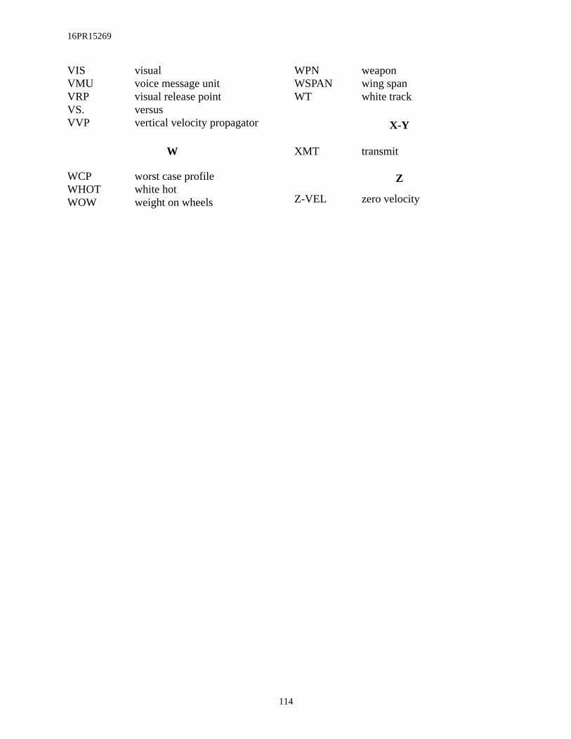
16PR15269
VIS visualVMU voice message unitVRP visual release pointVS. versusVVP vertical velocity propagator
W
WCP worst case profileWHOT white hotWOW weight on wheels
WPN weaponWSPAN wing spanWT white track
X-Y
XMT transmit
Z
Z-VEL zero velocity
114