Embed Size (px)
Citation preview
8/10/2019 f 788 – f 788m – 97 ;Rjc4oc9gnzg4ts1sruq
http://slidepdf.com/reader/full/f-788-f-788m-97-rjc4oc9gnzg4ts1sruq 1/8
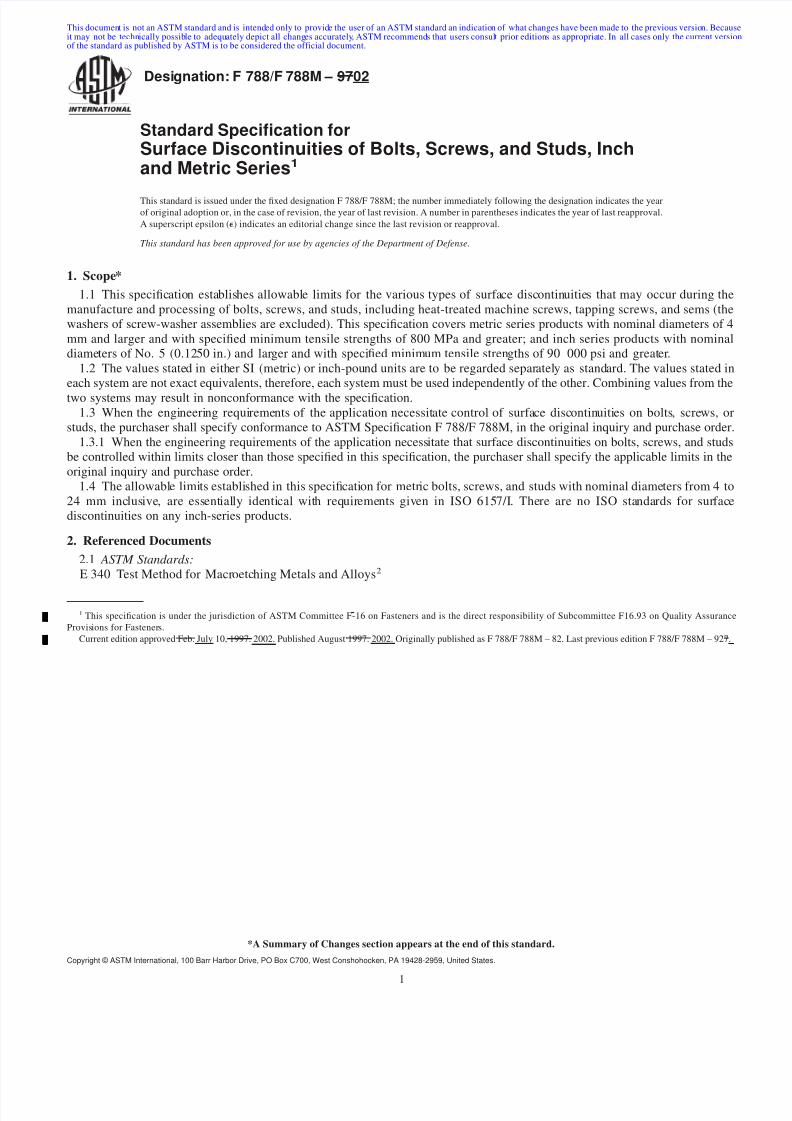
Designation: F 788/F 788M – 9702
Standard Specication forSurface Discontinuities of Bolts, Screws, and Studs, Inchand Metric Series 1
This standard is issued under the xed designation F 788/F 788M; the number immediately following the designation indicates the yearof original adoption or, in the case of revision, the year of last revision. A number in parentheses indicates the year of last reapproval.A superscript epsilon ( e ) indicates an editorial change since the last revision or reapproval.
This standard has been approved for use by agencies of the Department of Defense.
1. Scope*1.1 This specication establishes allowable limits for the various types of surface discontinuities that may occur during the
manufacture and processing of bolts, screws, and studs, including heat-treated machine screws, tapping screws, and sems (thewashers of screw-washer assemblies are excluded). This specication covers metric series products with nominal diameters of 4mm and larger and with specied minimum tensile strengths of 800 MPa and greater; and inch series products with nominaldiameters of No. 5 (0.1250 in.) and larger and with specied minimum tensile strengths of 90 000 psi and greater.
1.2 The values stated in either SI (metric) or inch-pound units are to be regarded separately as standard. The values stated ineach system are not exact equivalents, therefore, each system must be used independently of the other. Combining values from thetwo systems may result in nonconformance with the specication.
1.3 When the engineering requirements of the application necessitate control of surface discontinuities on bolts, screws, orstuds, the purchaser shall specify conformance to ASTM Specication F 788/F 788M, in the original inquiry and purchase order.
1.3.1 When the engineering requirements of the application necessitate that surface discontinuities on bolts, screws, and studsbe controlled within limits closer than those specied in this specication, the purchaser shall specify the applicable limits in theoriginal inquiry and purchase order.
1.4 The allowable limits established in this specication for metric bolts, screws, and studs with nominal diameters from 4 to24 mm inclusive, are essentially identical with requirements given in ISO 6157/I. There are no ISO standards for surfacediscontinuities on any inch-series products.
2. Referenced Documents2.1 ASTM Standards:E 340 Test Method for Macroetching Metals and Alloys 2
1 This specication is under the jurisdiction of ASTM Committee F-16 on Fasteners and is the direct responsibility of Subcommittee F16.93 on Quality AssuranceProvisions for Fasteners.
Current edition approved Feb. July 10, 1997. 2002. Published August 1997. 2002. Originally published as F 788/F 788M – 82. Last previous edition F 788/F 788M – 927.
1
This document is not an ASTM standard and is intended only to provide the user of an ASTM standard an indication of what changes have been made to the previous version. Becauseit may not be technically possible to adequately depict all changes accurately, ASTM recommends that users consult prior editions as appropriate. In all cases only the current versionof the standard as published by ASTM is to be considered the official document.
*A Summary of Changes section appears at the end of this standard.
Copyright © ASTM International, 100 Barr Harbor Drive, PO Box C700, West Conshohocken, PA 19428-2959, United States.
8/10/2019 f 788 – f 788m – 97 ;Rjc4oc9gnzg4ts1sruq
http://slidepdf.com/reader/full/f-788-f-788m-97-rjc4oc9gnzg4ts1sruq 2/8
F 1470 Standard Guide for Fastener Sampling for Specied Mechanical Properties and Performance Inspection 3
F 1789 Standard Terminology for F16 Mechanical Fasteners 3
2.2 ISO Standard: 4
ISO 6157/I Fasteners, Surface Discontinuities on Bolts, Screws and Studs
3. Ordering Information3.1 Orders for bolts, screws, and studs requiring discontinuity control shall include the following:
3.1.1 ASTM designation and date of issue of this specication.3.1.2 Special requirements, for example, closer discontinuity limits (1.3.1) and inspection sampling plan (6.2).
4. Types of Surface Discontinuities (see Terminology F 1789 for denitions not provided)4.1 Crack —A crack is a clean (crystalline) fracture passing through or across the grain boundaries and may possibly follow
inclusions of foreign elements. Cracks are normally caused by overstressing the metal during forging or other forming operations,or during heat treatment. Where parts are subjected to signicant reheating, cracks usually are discolored by scale.
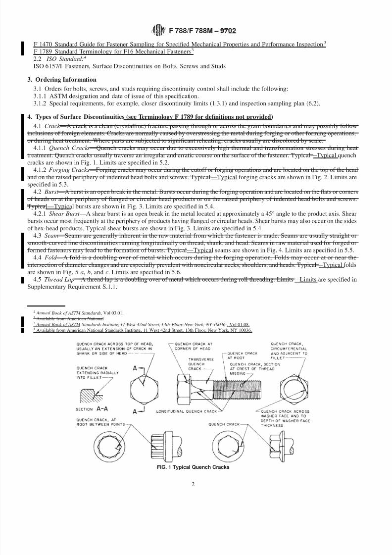
4.1.1 Quench Cracks —Quench cracks may occur due to excessively high thermal and transformation stresses during heattreatment. Quench cracks usually traverse an irregular and erratic course on the surface of the fastener. Typical—Typical quenchcracks are shown in Fig. 1. Limits are specied in 5.2.
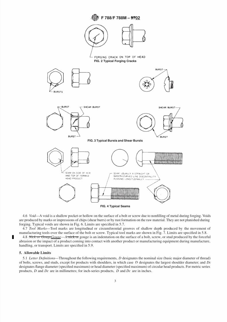
4.1.2 Forging Cracks —Forging cracks may occur during the cutoff or forging operations and are located on the top of the headand on the raised periphery of indented head bolts and screws. Typical—Typical forging cracks are shown in Fig. 2. Limits arespecied in 5.3.
4.2 Burst —A burst is an open break in the metal. Bursts occur during the forging operation and are located on the ats or cornersof heads or at the periphery of anged or circular head products or on the raised periphery of indented head bolts and screws.Typical—Typical bursts are shown in Fig. 3. Limits are specied in 5.4.
4.2.1 Shear Burst —A shear burst is an open break in the metal located at approximately a 45° angle to the product axis. Shearbursts occur most frequently at the periphery of products having anged or circular heads. Shear bursts may also occur on the sidesof hex-head products. Typical shear bursts are shown in Fig. 3. Limits are specied in 5.4.
4.3 Seam —Seams are generally inherent in the raw material from which the fastener is made. Seams are usually straight orsmooth-curved line discontinuities running longitudinally on thread, shank, and head. Seams in raw material used for forged orformed fasteners may lead to the formation of bursts. Typical—Typical seams are shown in Fig. 4. Limits are specied in 5.5.
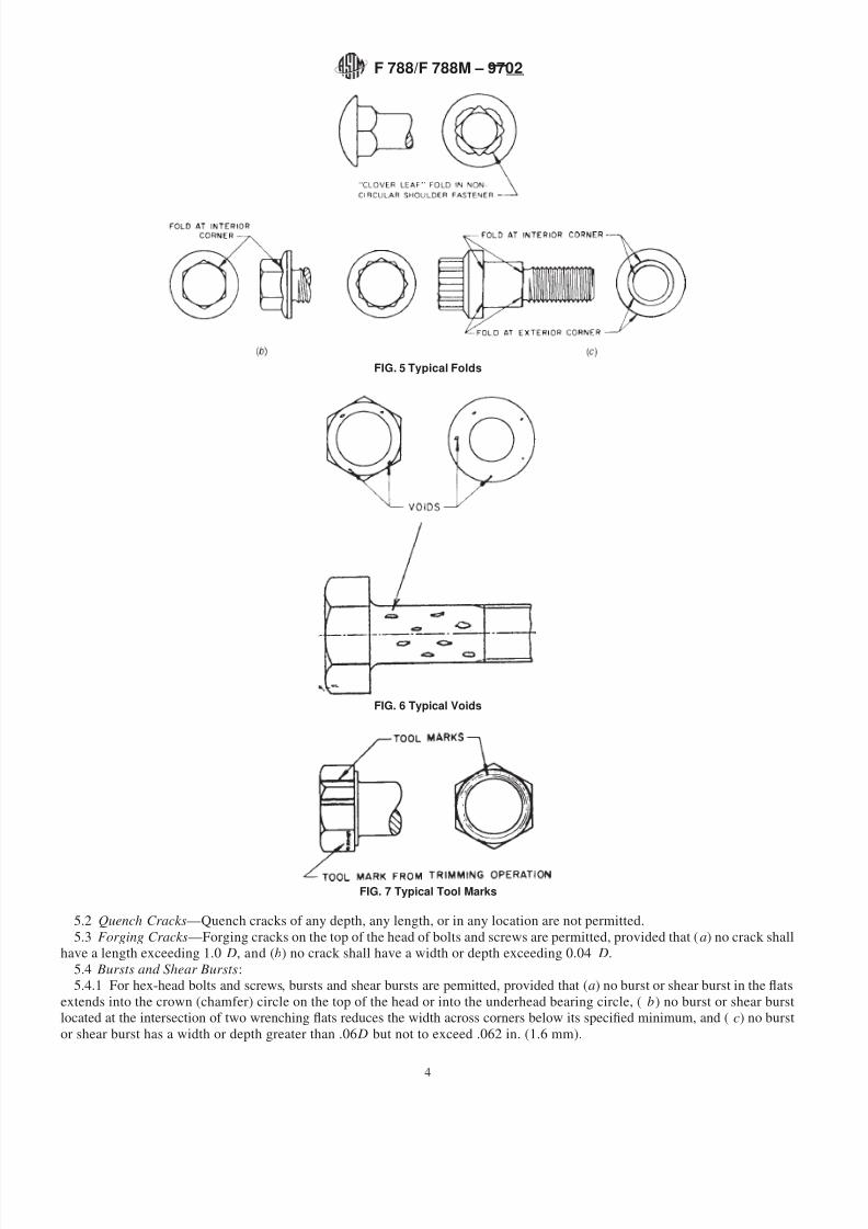
4.4 Fold —A fold is a doubling over of metal which occurs during the forging operation. Folds may occur at or near theintersection of diameter changes and are especially prevalent with noncircular necks, shoulders, and heads. Typical—Typical foldsare shown in Fig. 5 a, b, and c. Limits are specied in 5.6.
4.5 Thread Lap —A thread lap is a doubling over of metal which occurs during roll threading. Limits—Limits are specied inSupplementary Requirement S.1.1.
2 Annual Book of ASTM Standards , Vol 03.01.3 Available from American National3 Annual Book of ASTM Standards Institute, 11 West 42nd Street, 13th Floor, New York, NY 10036. , Vol 01.08.4 Available from American National Standards Institute, 11 West 42nd Street, 13th Floor, New York, NY 10036.
FIG. 1 Typical Quench Cracks
F 788/F 788M – 9702
2
8/10/2019 f 788 – f 788m – 97 ;Rjc4oc9gnzg4ts1sruq
http://slidepdf.com/reader/full/f-788-f-788m-97-rjc4oc9gnzg4ts1sruq 3/8
4.6 Void —A void is a shallow pocket or hollow on the surface of a bolt or screw due to nonlling of metal during forging. Voidsare produced by marks or impressions of chips (shear burrs) or by rust formation on the raw material. They are not planished during
forging. Typical voids are shown in Fig. 6. Limits are specied in 5.7.4.7 Tool Marks —Tool marks are longitudinal or circumferential grooves of shallow depth produced by the movement of manufacturing tools over the surface of the bolt or screw. Typical tool marks are shown in Fig. 7. Limits are specied in 5.8.
4.8 Nick or GougeGouge —A nick or gouge is an indentation on the surface of a bolt, screw, or stud produced by the forcefulabrasion or the impact of a product coming into contact with another product or manufacturing equipment during manufacture,handling, or transport. Limits are specied in 5.9.
5. Allowable Limits5.1 Letter Denitions —Throughout the following requirements, D designates the nominal size (basic major diameter of thread)
of bolts, screws, and studs, except for products with shoulders, in which case D designates the largest shoulder diameter; and Dcdesignates ange diameter (specied maximum) or head diameter (specied maximum) of circular head products. For metric seriesproducts, D and Dc are in millimetres; for inch-series products, D and Dc are in inches.
FIG. 2 Typical Forging Cracks
FIG. 3 Typical Bursts and Shear Bursts
FIG. 4 Typical Seams
F 788/F 788M – 9702
3
8/10/2019 f 788 – f 788m – 97 ;Rjc4oc9gnzg4ts1sruq
http://slidepdf.com/reader/full/f-788-f-788m-97-rjc4oc9gnzg4ts1sruq 4/8
5.2 Quench Cracks —Quench cracks of any depth, any length, or in any location are not permitted.5.3 Forging Cracks —Forging cracks on the top of the head of bolts and screws are permitted, provided that ( a ) no crack shall
have a length exceeding 1.0 D, and (b) no crack shall have a width or depth exceeding 0.04 D.5.4 Bursts and Shear Bursts :5.4.1 For hex-head bolts and screws, bursts and shear bursts are permitted, provided that ( a ) no burst or shear burst in the ats
extends into the crown (chamfer) circle on the top of the head or into the underhead bearing circle, ( b) no burst or shear burstlocated at the intersection of two wrenching ats reduces the width across corners below its specied minimum, and ( c) no burstor shear burst has a width or depth greater than .06 D but not to exceed .062 in. (1.6 mm).
FIG. 5 Typical Folds
FIG. 6 Typical Voids
FIG. 7 Typical Tool Marks
F 788/F 788M – 9702
4
8/10/2019 f 788 – f 788m – 97 ;Rjc4oc9gnzg4ts1sruq
http://slidepdf.com/reader/full/f-788-f-788m-97-rjc4oc9gnzg4ts1sruq 5/8
5.4.2 For ange bolts and screws and products with circular heads, bursts and shear bursts at the periphery of the ange or headare permitted, provided that ( a ) not more than one burst or shear burst has a width greater than 0.04 Dc and (b) the width of theone burst or shear burst that exceeds a width of 0.04 Dc does not have a width greater than 0.08 Dc.
5.4.3 For indented head bolts and screws, bursts and shear bursts in the raised periphery of the indented head are permitted,provided that ( a ) no burst or shear burst has a width greater than 0.06 D and (b) no burst or shear burst has a depth extending belowthe indented portion.
5.5 Seams :5.5.1 Seams in the shanks of bolts, screws, and studs are permitted provided that no seam has a depth greater than 0.03 D .5.5.2 Seams extending into the heads and anges of bolts and screws are permitted, provided that they do not open beyond the
limits specied for bursts and shear bursts in 5.4.5.6 Folds :5.6.1 Folds located at interior corners that are at or below the underhead bearing surface, for example, at the junction of head
to shank, are not permitted, except for cloverleaf folds occurring at the intersection of non-circular shoulders with head bearingface (see Fig. 5 a ).
5.6.2 Folds located at interior corners that are above the underhead bearing surface, for example, at the junction of the hex headwith the top of ange of ange bolts and screws, are permitted (see Fig. 5 b).
5.6.3 Folds located at exterior corners are permitted (see Fig. 5 c).5.7 Voids :
5.7.1 Voids on the surfaces of bolts, screws, and studs are permitted, provided that ( a ) depth of voids does not exceed 0.25 mmor 0.010 in. or 0.02 D , whichever is greater, and ( b) the combined area of all voids on the underhead bearing surface of bolts andscrews does not exceed 10 % of the specied minimum bearing surface area.
5.7.2 The method for determining the area of voids on the bearing surface shall be as agreed upon between the purchaser andthe producer.
5.8 Tool Marks :5.8.1 Tool marks on the underhead bearing surface are permitted, provided the surface roughness measurement does not exceed
3.2 µm or 125 µin., determined as the arithmetic average deviation from the mean surface.5.8.2 Tool marks on other surfaces of the product are permitted.5.9 Nicks and Gouges —Nicks, gouges, dents, and scrapes are permitted, provided that the functionability of the product is not
impaired.
6. Inspection and Evaluation6.1 Bolts, screws, and studs shall be inspected for surface discontinuities in accordance with the procedure in 6.2, 6.3, and 6.4.6.2 The purchaser shall specify in the original inquiry and purchase order the inspection sampling requirements that the
producer must satisfy to demonstrate the acceptability of bolts, screws, and studs with respect to surface discontinuities.6.3 In the absence of purchaser instructions (6.2), inspection and evaluation shall be in accordance with 6.5.6.4 For referee purposes, unless other procedures have been specied by the purchaser (6.2), inspection and evaluation shall be
in accordance with 6.5.6.5 Inspection Procedure :6.5.1 Visual Inspection :6.5.1.1 A random sample shall be taken from the lot in accordance with Table 1 F 1470 and examined visually (magnetic particle
or uid penetrant are recommended) for the presence of quench cracks, forging cracks, bursts, shear bursts, seams, folds, voids,
tool marks, and nicks and gouges. Visual inspection can include the use of devices that provide up to, and including, 10-powermagnication.6.5.1.2 If, during this inspection, any products are found with quench cracks in any location or with folds at interior corners that
are at or below the underhead bearing surface, the lot may be rejected by the purchaser.6.5.1.3 If, during this inspection, any products are found with any other surface discontinuity, each discontinuity shall be
measured, and if any is found that exceeds the allowable dimensional limits for that discontinuity as specied in Section5, the lotmay be rejected by the purchaser.
7. Keywords
7.1 bolts; crack; discontinuities (surface); fold; screw (machine, sems, tapping); seam; studs; thread lap; void
F 788/F 788M – 9702
5
8/10/2019 f 788 – f 788m – 97 ;Rjc4oc9gnzg4ts1sruq
http://slidepdf.com/reader/full/f-788-f-788m-97-rjc4oc9gnzg4ts1sruq 6/8
SUPPLEMENTARY REQUIREMENTS
One or more of the following supplementary requirements shall apply only when specied by thepurchaser in the inquiry and order. Supplementary Requirements shall in no way negate anyrequirement of the specication itself.
S1. Assemblies Subject to Severe Dynamic Stresses
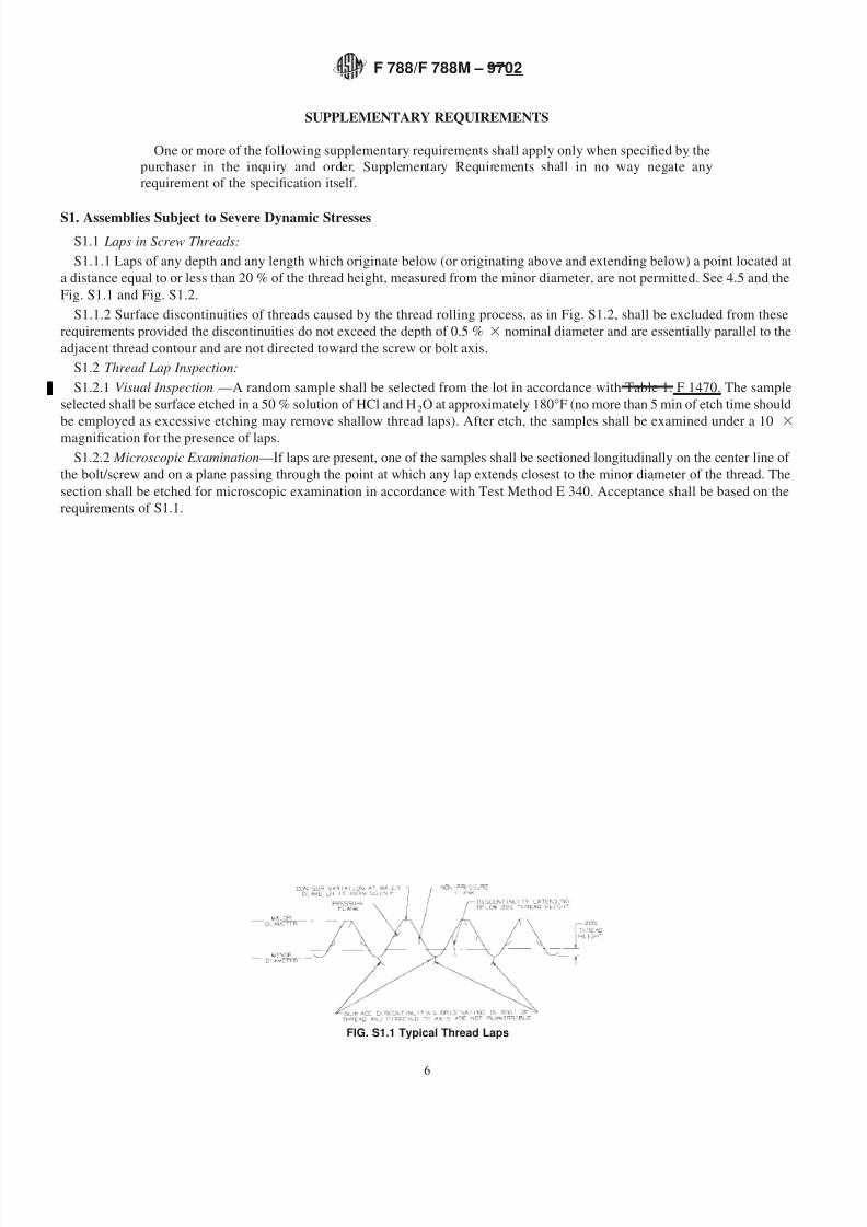
S1.1 Laps in Screw Threads:S1.1.1 Laps of any depth and any length which originate below (or originating above and extending below) a point located at
a distance equal to or less than 20 % of the thread height, measured from the minor diameter, are not permitted. See 4.5 and theFig. S1.1 and Fig. S1.2.
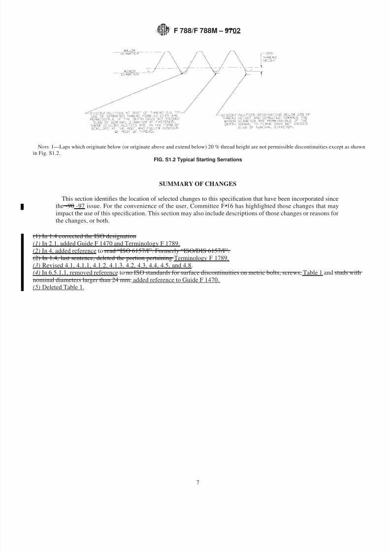
S1.1.2 Surface discontinuities of threads caused by the thread rolling process, as in Fig. S1.2, shall be excluded from theserequirements provided the discontinuities do not exceed the depth of 0.5 % 3 nominal diameter and are essentially parallel to theadjacent thread contour and are not directed toward the screw or bolt axis.
S1.2 Thread Lap Inspection:S1.2.1 Visual Inspection —A random sample shall be selected from the lot in accordance with Table 1. F 1470. The sample
selected shall be surface etched in a 50 % solution of HCl and H 2 O at approximately 180°F (no more than 5 min of etch time shouldbe employed as excessive etching may remove shallow thread laps). After etch, the samples shall be examined under a 10 3
magnication for the presence of laps.S1.2.2 Microscopic Examination —If laps are present, one of the samples shall be sectioned longitudinally on the center line of
the bolt/screw and on a plane passing through the point at which any lap extends closest to the minor diameter of the thread. Thesection shall be etched for microscopic examination in accordance with Test Method E 340. Acceptance shall be based on therequirements of S1.1.
FIG. S1.1 Typical Thread Laps
F 788/F 788M – 9702
6
8/10/2019 f 788 – f 788m – 97 ;Rjc4oc9gnzg4ts1sruq
http://slidepdf.com/reader/full/f-788-f-788m-97-rjc4oc9gnzg4ts1sruq 7/8
SUMMARY OF CHANGES
This section identies the location of selected changes to this specication that have been incorporated sincethe -90 -97 issue. For the convenience of the user, Committee F-16 has highlighted those changes that mayimpact the use of this specication. This section may also include descriptions of those changes or reasons forthe changes, or both.
(1) In 1.4 corrected the ISO designation(1) In 2.1, added Guide F 1470 and Terminology F 1789.(2) In 4, added reference to read “ISO 6157/I”. Formerly “ISO/DIS 6157/I”.(2) In 1.4, last sentence, deleted the portion pertaining Terminology F 1789.(3) Revised 4.1, 4.1.1, 4.1.2, 4.1.3, 4.2, 4.3, 4.4, 4.5, and 4.8.(4) In 6.5.1.1, removed reference to no ISO standards for surface discontinuities on metric bolts, screws, Table 1 and studs withnominal diameters larger than 24 mm. added reference to Guide F 1470.(5) Deleted Table 1.
NOTE 1—Laps which originate below (or originate above and extend below) 20 % thread height are not permissible discontinuities except as shownin Fig. S1.2.
FIG. S1.2 Typical Starting Serrations
F 788/F 788M – 9702
7
8/10/2019 f 788 – f 788m – 97 ;Rjc4oc9gnzg4ts1sruq
http://slidepdf.com/reader/full/f-788-f-788m-97-rjc4oc9gnzg4ts1sruq 8/8
ASTM International takes no position respecting the validity of any patent rights asserted in connection with any item mentioned in this standard. Users of this standard are expressly advised that determination of the validity of any such patent rights, and the risk of infringement of such rights, are entirely their own responsibility.
This standard is subject to revision at any time by the responsible technical committee and must be reviewed every ve years and if not revised, either reapproved or withdrawn. Your comments are invited either for revision of this standard or for additional standards and should be addressed to ASTM International Headquarters. Your comments will receive careful consideration at a meeting of the responsible technical committee, which you may attend. If you feel that your comments have not received a fair hearing you should make your views known to the ASTM Committee on Standards, at the address shown below.
This standard is copyrighted by ASTM International, 100 Barr Harbor Drive, PO Box C700, West Conshohocken, PA 19428-2959,United States. Individual reprints (single or multiple copies) of this standard may be obtained by contacting ASTM at the above address or at 610-832-9585 (phone), 610-832-9555 (fax), or [email protected] (e-mail); or through the ASTM website (www.astm.org).
F 788/F 788M – 9702
8