Embed Size (px)
Citation preview

F111.HT.01 Hot Tap Turbine Flow Sensor1
F111.HT.01 Turbine Flow Sensor for HotTap Installation
INSTRUCTION MANUAL
EN 10-11
Table of Contents
1. Introduction………………………………………………………………… 2
Safety Instructions……………………………………………………….……………… 2Unpacking………………………………………………………………….……………… 2
2. Description…………………………………………………………………. 2
Main Features……………………………………………………….…………………….. 3Technical Data…….……………………………………............………………………… 3
3. Installation…..……………………………………………………………… 4
Location………………………………………………………….………………………… 4Dimensions………………………………………….……............……………………… 4Set the sensor to work………………………..…………………..…………………….. 5Wiring…………………………………………………………..…………………………… 8
4. K-Factor Tables……………………………………………………………. 9

F111.HT.01 Hot Tap Turbine Flow Sensor2
1. Introduction
1.1. Safety Instructions
General Statements
The sensor F111.HT.01 has only been designed to measure the flow of liquids. Do not install and service the sensor without following the Instruction Manual. This sensor is designed to be connected to other instruments which can be
hazardous if used improperly. Read and follow all associated instrumentmanuals before using with this sensor.
Sensor installation and wiring connections should only be performed by qualifiedstaff.
Do not modify product construction.
Installation and Commissioning Statements
Remove power to the sensor before wiring any connection. Remove pressure from the pipe if an hot-tap installation adapter is NOT used. Do not exceed maximum temperature/pressure data. For hot tap installation the pressure limitations are related to the minimum
maximum value of the used components (like saddles or valves). To clean the sensor, use only chemical compatible products.
1.2. Unpacking
Please verify the product is complete and without any damage. The package shouldinclude:
A steel tube rod with flow sensor integrated A steel joint for screwing the sensor to the saddle A safety chain An instruction manual
2. Description
The new turbine flow sensor F111.HT.01 is designed for use with every kind of solid –freeliquids. The sensor can measure flow from 0.08 m/s (0.26 ft/s) producing a frequencyoutput signal highly repeatable. A stainless steel rugged construction and a proventechnology guarantee exceptional performances with little or no maintenance required.The electronic is entirely encapsulated in epoxy resin which ensures that the instrument issuitable for corrosive or high humidity atmospheres.The sensor can be assembled in pressurised pipes using a proper fitting (clamp saddle orweld-on adapter with valve enclosed).

F111.HT.01 Hot Tap Turbine Flow Sensor3
2.1. Main Features
Adjustable sensor position Stainless Steel construction with insertion turbine technology PVDF turbine with ceramic shaft and bearings Wet-tap installation Pressure intake Suitable for assembling on a wide range of wet-tap clamp saddles with 1 1/4” GAS
branch Safety chain Compatible with most data logger on the market
2.2. Technical Data
GeneralFlow Rate Range: 0.08 to 8 m/s (0.26 to 4.9 ft./s)Linearity: 0.75 % of full scaleRepeatability: 0.5 % of full scalePipe Size Range: DN 50 to DN 1200 ( 2” to 48”), for sizes bigger than DN 600
(24”) contact the factoryMinimum Reynolds Number Required: 4500Enclosure: IP68Max. operating pressure/temperature: 20 bar (290 psi) @ 80°C (176°F)Wetted Materials:
Sensor Body: 304 SSO-rings: EPDM or FPMTurbine: PVDFShaft: Ceramic (Al2O3)Bearings: Ceramic (Al2O3)measuring rod: 304 SSfixing joint: 304 SS
Pressure intake: quick connection 1/4”Thread of the fixingjoint to the saddle: GAS 1 1/4”
ElectricalSupply voltage: 5 to 24 VDC ±10% regulatedSupply current: < 30 mA @ 24 VDCOutput signal: square waveOutput frequency: 20 Hz/ms nominalOutput type: transistor NPN open collectorOutput current: 10 mA max.Cable length: 8 m (26.4 ft) standard, 100 m (330 ft) maximum
Standards & ApprovalsManufactured under ISO 9001 (Quality)Manufactured under ISO 14000 (Environmental Management)CE

F111.HT.01 Hot Tap Turbine Flow Sensor4
3. Installation
3.1. Location
Different pipe configurations and obstacles in the flow line such as valves, elbows, pipebends and strainers create variations on the flow profile.Whenever possible follow the EN ISO 5167-1 installation recommendations to locatethe sensor.
Always maximize distance between flow sensor and pump.
3.2. Dimensions
Fig 1

F111.HT.01 Hot Tap Turbine Flow Sensor5
3.3. Set the sensor to work
The assembly and set to work of the instrument are carried out by two simple steps thatallow a quick and precise installation:
1. INSTALLATION OF THE SENSOR ON THE WET-TAP CLAMP SADDLE2. VERTICAL POSITIONING OF THE SENSOR INTO THE PIPE
Warning: the FLS F111.HT.01 allows installation into pressurised pipes withoutsystem shutdown; we recommend to pay maximum attention when screwingthe clamping bolts of the measuring rod. The rod is pushed upwards by theinternal pressure, for this reason not work up the rob.
Note: lubricate the steel rod to reduce frictions with the O-rings. This will help theinstallation, measurement and positioning operations.
1. INSTALLATION OF THE SENSOR ON THE WET-TAP CLAMP SADDLE
Warning: these installations steps can be applied to every wet-tap clamp saddle withthe following properties:
Branch minimum diameter : 35 mm Branch thread : 1 1/4” GAS (cylindrical)
Fig 2

F111.HT.01 Hot Tap Turbine Flow Sensor6
a) Assemble the saddle in the desired position to install the sensor.Drill the pipe. Use a 35 mm ( in.) milling cutter.Remove the drilling machine. Be careful to block the fluid using the proper interceptingplate or ball valve.
b) Wrap several turns of Teflon tape around the steel joint threads to prevent leaks. Screwthe Stainless Steel joint, together with the measuring rod and the sensor, in the saddlebranch.
c) Be careful to fix the sensor body in the upper position.
d) Tight the safety chain and fix it.
e) Remove the intercepting plate or open the ball valve to the full open position(perpendicular to pipe).
2. VERTICAL POSITIONING OF THE SENSOR INTO THE PIPE
a) Be sure the sensor is in the upper position.
Fig 3
Fig 4

F111.HT.01 Hot Tap Turbine Flow Sensor7
b) Calculate DISTANCE between sliding bush and sensor body:
For pipe sizes smaller than DN 250 (10”):DISTANCE (mm) = [ 0.5 x Internal Diameter ] + S + K
For pipe sizes equal or greater than DN 250 (10”):DISTANCE (mm) = [ 0.12 x Internal Diameter ] + S + K
S = thickness pipeK = distance between external pipe and end of the thread
c) Move and fix the sliding bush at the calculated DISTANCE from the Stainless Steeljoint:
Fig 6
Fig 5
F111.HT.01 Hot Tap Turbine Flow Sensor8
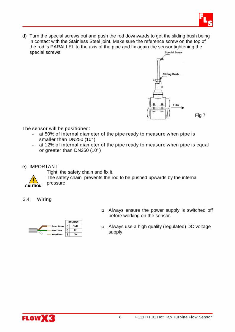
d) Turn the special screws out and push the rod downwards to get the sliding bush beingin contact with the Stainless Steel joint. Make sure the reference screw on the top ofthe rod is PARALLEL to the axis of the pipe and fix again the sensor tightening thespecial screws.
The sensor will be positioned:- at 50% of internal diameter of the pipe ready to measure when pipe is
smaller than DN250 (10”)- at 12% of internal diameter of the pipe ready to measure when pipe is equal
or greater than DN250 (10”)
e) IMPORTANTTight the safety chain and fix it.The safety chain prevents the rod to be pushed upwards by the internalpressure.
3.4. Wiring
Always ensure the power supply is switched offbefore working on the sensor.
Always use a high quality (regulated) DC voltagesupply.
Fig 7

F111.HT.01 Hot Tap Turbine Flow Sensor9
4. K-Factor Tables
K-Factor values for sensor central positioning
DN(mm) k-Factor80 (3”) 4.08
100 (4”) 2.60110 2.14125 1.62
150 (6”) 1.12180 0.88
200 (8”) 0.62225 0.48
K-Factor values for sensor 12% positioning
DN(mm) k-Factor250 (10”) 0.28300 (12”) 0.20350 (14”) 0.14400 (16”) 0.12450 (18”) 0.10500 (20”) 0.08600 (24”) 0.06700 (28”) 0.04800 (32”) 0.02900 (36”) On request
1000 (40”) On request1100 (44”) On request1200 (48”) On request
Correction formula for K-Factor calculation according to real internal diameter
K-Factor_NEW = (K-Factor x ID²) / ID_NEW²
where:ID = Value in the table for the internal diameter (in mm)ID_NEW = New value for the real internal diameter (always in mm)K-Factor = Value in the tableK-Factor_NEW = New K-Factor value for the specified internal diameter
EXAMPLE:Nominal Pipe Size (DN) = 40 mmNew Internal Diameter = 44,7 mm
Using the formula: K-Factor_NEW = (32,74 x 45,3²) / 44,7² = 33,62

F111.HT.01 Hot Tap Turbine Flow Sensor10

F111.HT.01 Hot Tap Turbine Flow Sensor11

F111.HT.01 Hot Tap Turbine Flow Sensor12
F.I.P. Formatura Iniezione Polimeri S.p.A.Loc. Pian di Parata, 16015 Casella (GE) – Italy
Tel +39 010 96211 – Fax +39 010 9621209
www.flsnet.it