Embed Size (px)
Citation preview
� � � � � � � � � � � ������� � �
� �
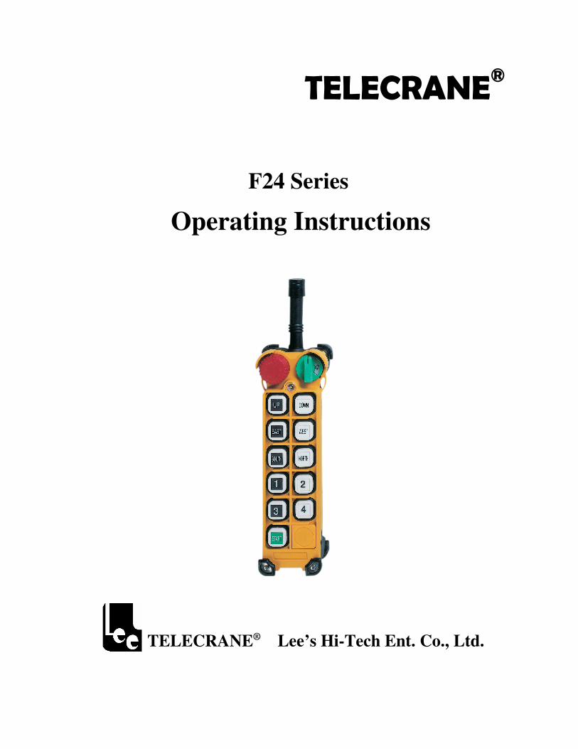
F24 Series
Operating Instructions��
� � �
� � � �
TELECRANE® Lee’s Hi-Tech Ent. Co., Ltd.
1
Table of Contents
� Warranty & Precautions of Operation..………….………..2
� F24 Operation………………...……………….…..………3
� F24 Software Installation & Operation. ……….…….……6 � Appendix I: Definition of Function Terminology………..10
2
Warranty Lee’s Hi-Tech Enterprises Co., Ltd. guarantees that this product meets its published specifications at the time of shipment from the factory. Under proper installation it should work as expected. Warranty Period This equipment is warranted against defects in material and manufacturing for a period of one year from the date of shipment. During the warranty period, TELECRANE is responsible for necessary repairs as long as the product can be proved to be defective. For warranty service or repair this product must be returned to a service facility designated by TELECRANE. Buyer will pay shipping charges to TELECRANE while TELECRANE will pay return shipping charges. Excluded Items
This warranty does not include consumptive parts such as batteries, fuses, buttons, relays. Also this warranty does not cover defects caused by improper installation, improper or insufficient maintenance, unauthorized modification, improper operation, ignorance of environmental specifications, or improper software or interfacing. Remarks
No other warranty is expressed or implied, except for the above mentioned. The remedies provided herein are the buyer’s sole and exclusive remedies. TELECRANE shall not be liable for any direct, indirect, special, incidental or consequential damages.
Attention
Never dismantle the equipment by any unauthorized personnel, or equipment may be damaged. After finishing operation of TELECRANE radio controller shut off main power to the crane, power to receiver, and remove transmitter key. If transmitter’s power is controlled by “rotary key switch”, then need turn the key to “OFF” position and remove it. The crane should be equipped with main power relay, limit switch and other safety devices.
Precautions ( I ) To avoid any interference, the receiver must be placed as far as possible from frequency inverter and power cable as possible. Precaution ( II ) The receiver should be installed on the top of the electrical control box. Do not mount the receiver inside the electrical control box.
Emergency In case of Emergency, please follow the procedure below and contact the distributor for service immediately. 1. Press EMS button of transmitter. 2. Remove the key from transmitter. 3. Switch off the main power of crane. 4. Contact distributor nearest you immediately.
����������������� � � � � � �� �� � � � � � � �� �� � �� � � � � � �� � � � � � �� �� � � � � � � �� �� � �� � � � � � �� � � � � � �� �� � � � � � � �� �� � �� � � � � � �� � � � � � �� �� � � � � � � �� �� � �� � � � � � �����
3
How to start
1. Insert 2 AA-size alkaline batteries into battery compartment. 2. Insert rotary key and switch to ON position. 3. Follow the Power-On procedure to energize the main relay inside receiver. 4. Operate normally according to the function settings have been done. 5. After operation, please proceed as following: (1) Press EMS pushbutton /mushroom, (2) remove the key and keep
it in safe place, (3) Switch off the equipment’s main power (e.g. Crane)
How to change quartz from transmitter/ receiver & identify frequency quartz It’s simple to change frequency of the new F24 series. The system’s frequency can be changed simply by replacing correspondent frequency quartz in both TX and RX.
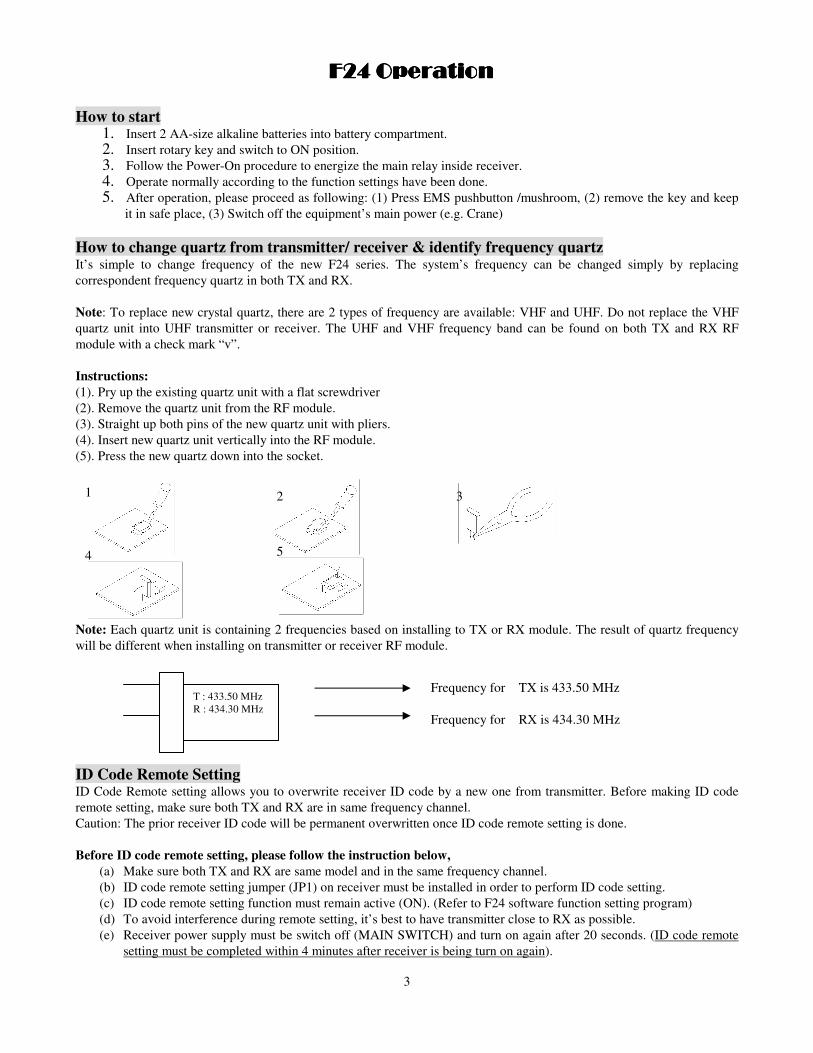
Note: To replace new crystal quartz, there are 2 types of frequency are available: VHF and UHF. Do not replace the VHF quartz unit into UHF transmitter or receiver. The UHF and VHF frequency band can be found on both TX and RX RF module with a check mark “v”. Instructions: (1). Pry up the existing quartz unit with a flat screwdriver (2). Remove the quartz unit from the RF module. (3). Straight up both pins of the new quartz unit with pliers. (4). Insert new quartz unit vertically into the RF module. (5). Press the new quartz down into the socket.
Note: Each quartz unit is containing 2 frequencies based on installing to TX or RX module. The result of quartz frequency
will be different when installing on transmitter or receiver RF module. ID Code Remote SettingID Code Remote setting allows you to overwrite receiver ID code by a new one from transmitter. Before making ID code remote setting, make sure both TX and RX are in same frequency channel. Caution: The prior receiver ID code will be permanent overwritten once ID code remote setting is done. Before ID code remote setting, please follow the instruction below,
(a) Make sure both TX and RX are same model and in the same frequency channel. (b) ID code remote setting jumper (JP1) on receiver must be installed in order to perform ID code setting. (c) ID code remote setting function must remain active (ON). (Refer to F24 software function setting program) (d) To avoid interference during remote setting, it’s best to have transmitter close to RX as possible. (e) Receiver power supply must be switch off (MAIN SWITCH) and turn on again after 20 seconds. (ID code remote
setting must be completed within 4 minutes after receiver is being turn on again).
1 2 3
4 5
T : 433.50 MHz R : 434.30 MHz
Frequency for TX is 433.50 MHz Frequency for RX is 434.30 MHz
����� � � � � ������ � � � � ������ � � � � ������ � � � � � �����
4
Instructions: (1) Turn off receiver power supply completely (MAIN SWITCH) and turn on again after 20 seconds. (2) Press transmitter Emergency Stop (3) Press UP pushbutton and hold it (Do not release UP pushbutton until next step is completed). (4) Press DOWN pushbutton 4 times and release “STOP & UP” pushbuttons when red LED flash. (5) Start the system as usual.
Note: (1) Any other receiver ID code with same model may be overwritten also if located within control distance. (2) ID code remote setting only transmits ID code data. No any other data will be overwritten.
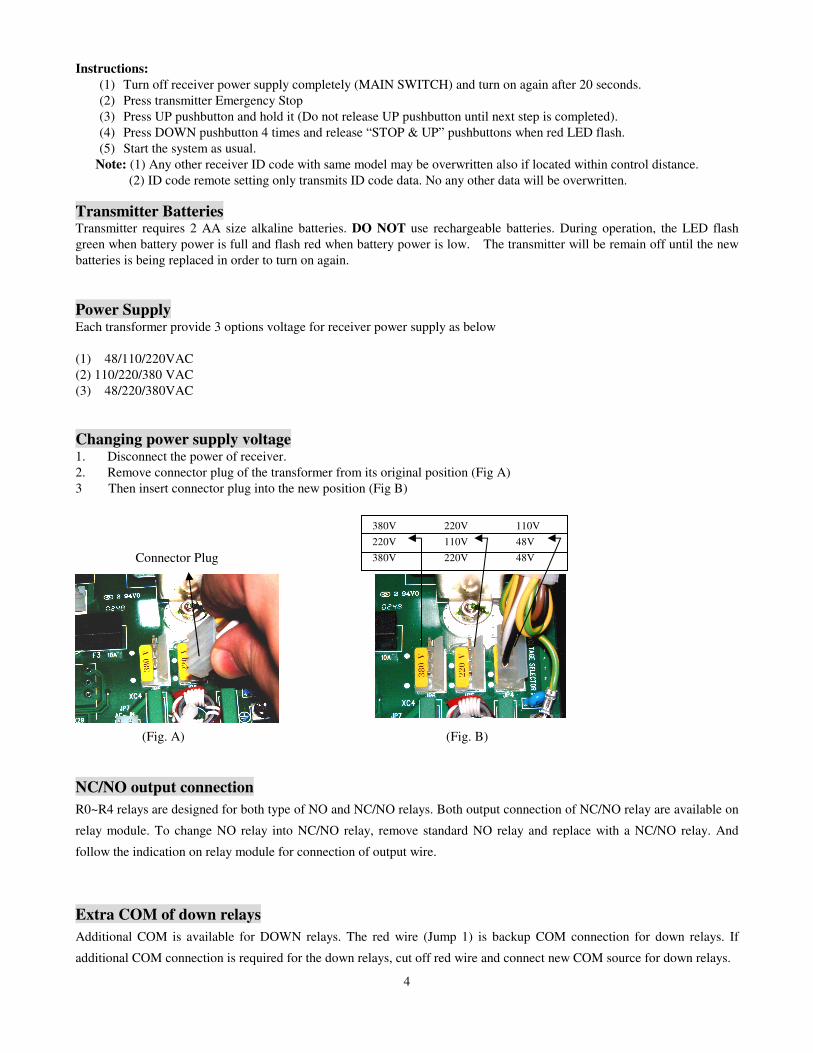
Transmitter Batteries Transmitter requires 2 AA size alkaline batteries. DO NOT use rechargeable batteries. During operation, the LED flash green when battery power is full and flash red when battery power is low. The transmitter will be remain off until the new batteries is being replaced in order to turn on again. Power Supply Each transformer provide 3 options voltage for receiver power supply as below (1) 48/110/220VAC (2) 110/220/380 VAC (3) 48/220/380VAC Changing power supply voltage 1. Disconnect the power of receiver. 2. Remove connector plug of the transformer from its original position (Fig A) 3 Then insert connector plug into the new position (Fig B)
(Fig. A) (Fig. B)
NC/NO output connection R0~R4 relays are designed for both type of NO and NC/NO relays. Both output connection of NC/NO relay are available on
relay module. To change NO relay into NC/NO relay, remove standard NO relay and replace with a NC/NO relay. And
follow the indication on relay module for connection of output wire.
Extra COM of down relays Additional COM is available for DOWN relays. The red wire (Jump 1) is backup COM connection for down relays. If
additional COM connection is required for the down relays, cut off red wire and connect new COM source for down relays.
110V 48V 48V
220V 110V 220V
380V 220V 380V Connector Plug
5
Transmitter LED malfunction alert (A) Red LED lamp flashing quickly (every 0.2 sec) when any pushbutton is being pressed. Causes:
(1) One of the pushbuttons is jammed. (2) The EMS mushroom is not released completely. (3) The transmitter is not properly Power-On according to the instructions. Note: Please contact the distributor nearest you for further assistant if need.
(B) TX LED flashes slowly (every 0.5 sec intermittent). Cause:
The transmitter memory is damaged. Contact the distributor for service. Troubleshooting (A) Symptom: TX LED remains ON with red light. Solution: Please remove the batteries and insert again. (B) Symptom: The RX does not respond at all. Solution: Switch off main power and switch on again after 20 seconds.
6
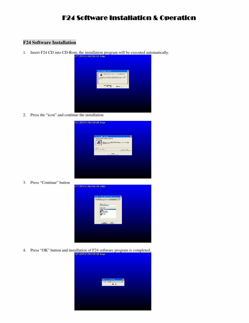
F24 Software Installation 1. Insert F24 CD into CD-Rom, the installation program will be executed automatically.
2. Press the “icon” and continue the installation
3. Press “Continue” button
4. Press “OK” button and installation of F24 software program is completed.
�������������� � � � � � �� �� � � � � � � ��� �� � � � � � ��� � � � � � �� �� � � � � � � ��� �� � � � � � ��� � � � � � �� �� � � � � � � ��� �� � � � � � ��� � � � � � �� �� � � � � � � ��� �� � � � � � ��
7
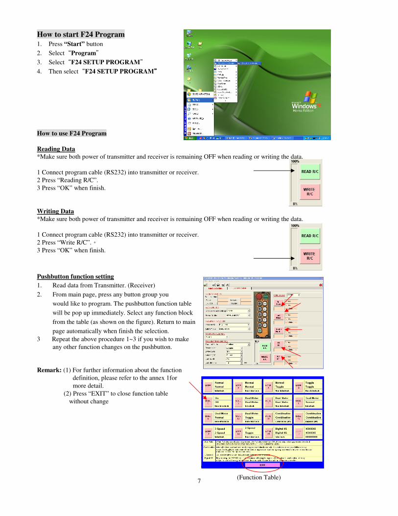
How to start F24 Program 1. Press “Start” button 2. Select Program 3. Select F24 SETUP PROGRAM 4. Then select F24 SETUP PROGRAM How to use F24 Program
Reading Data *Make sure both power of transmitter and receiver is remaining OFF when reading or writing the data. 1 Connect program cable (RS232) into transmitter or receiver. 2 Press “Reading R/C”. 3 Press “OK” when finish. Writing Data *Make sure both power of transmitter and receiver is remaining OFF when reading or writing the data.
1 Connect program cable (RS232) into transmitter or receiver.2 Press “Write R/C”.3 Press “OK” when finish.
Pushbutton function setting 1. Read data from Transmitter. (Receiver) 2. From main page, press any button group you
would like to program. The pushbutton function table will be pop up immediately. Select any function block from the table (as shown on the figure). Return to main page automatically when finish the selection.
3 Repeat the above procedure 1~3 if you wish to make any other function changes on the pushbutton.
Remark: (1) For further information about the function
definition, please refer to the annex 1for more detail.
(2) Press “EXIT” to close function table without change
(Function Table)
8
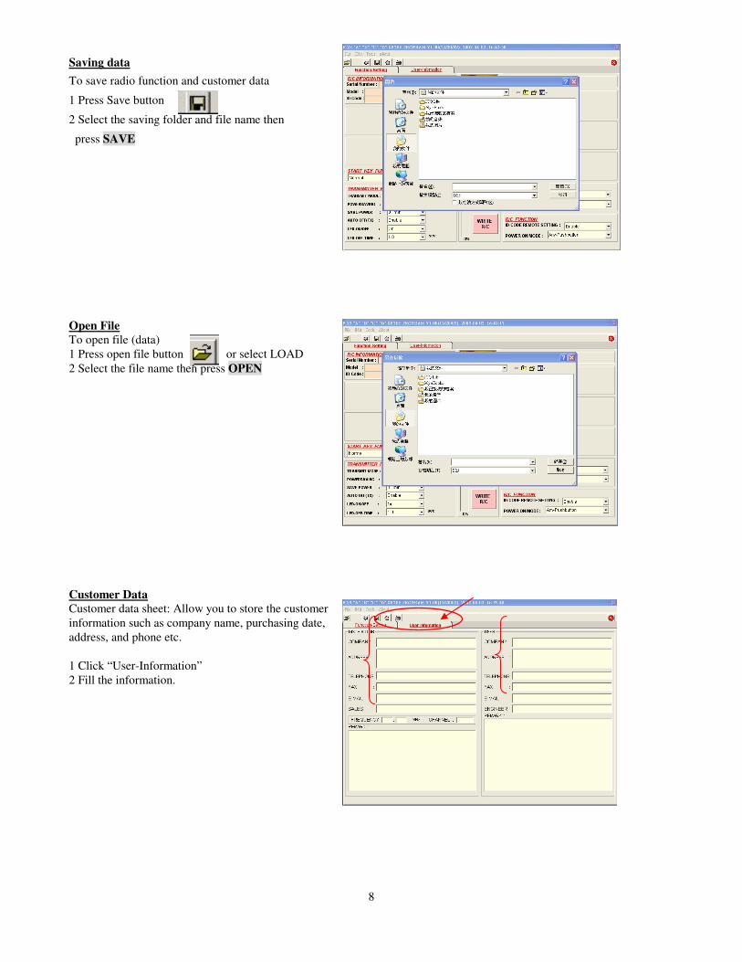
Saving dataTo save radio function and customer data
1 Press Save button
2 Select the saving folder and file name then
press SAVE
Open File To open file (data) 1 Press open file button or select LOAD 2 Select the file name then press OPEN
Customer Data Customer data sheet: Allow you to store the customer information such as company name, purchasing date, address, and phone etc. 1 Click “User-Information” 2 Fill the information.
9
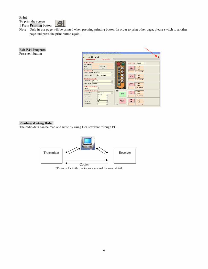
Print To print the screen 1 Press Printing button Note Only in-use page will be printed when pressing printing button. In order to print other page, please switch to another
page and press the print button again. Exit F24 Program Press exit button
Reading/Writing Data The radio data can be read and write by using F24 software through PC.
Transmitter
Copier *Please refer to the copier user manual for more detail.
Receiver
10
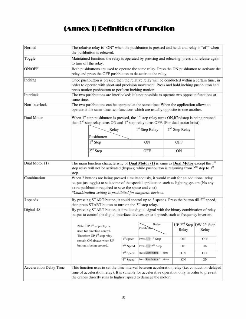
Normal The relative relay is “ON” when the pushbutton is pressed and held; and relay is “off” when
the pushbutton is released. Toggle Maintained function: the relay is operated by pressing and releasing; press and release again
to turn off the relay. ON/OFF Both pushbuttons are used to operate the same relay. Press the ON pushbutton to activate the
relay and press the OFF pushbutton to de-activate the relay.
Inching Once pushbutton is pressed then the relative relay will be conducted within a certain time, in order to operate with short and precision movement. Press and hold inching pushbutton and press motion pushbutton to perform inching motion.
Interlock The two pushbuttons are interlocked; it’s not possible to operate two opposite functions at same time.
Non-Interlock The two pushbuttons can be operated at the same time: When the application allows to operate at the same time two functions which are usually opposite to one another.
Dual Motor When 1st step pushbutton is pressed, the 1st step relay turns ON,if2ndstep is being pressed then 2nd step relay turns ON and 1st step relay turns OFF. (For dual motor hoist)
Relay
Pushbutton
1st Step Relay 2nd Step Relay
1st Step ON OFF
2nd Step OFF ON
Dual Motor (1) The main function characteristic of Dual Motor (1) is same as Dual Motor except the 1st step relay will not be activated (bypass) while pushbutton is returning from 2nd step to 1st step.
Combination When 2 buttons are being pressed simultaneously, it would result for an additional relay output (as toggle) to suit some of the special application such as lighting system.(No any extra pushbutton required to save the space and cost) *Combination setting is prohibited for magnetic devices.
3 speeds By pressing START button, it could control up to 3 speeds. Press the button till 2nd speed, then press START button to turn on the 3rd step relay.
Digital 4S By pressing START button, it simulate digital signal with the binary combination of relay output to control the digital interface devices up to 4 speeds such as frequency inverter.
Relay Pushbutton
UP 2nd Step Relay
DW 2nd Step Relay
1st Speed Press UP 1st Step OFF OFF
2nd Speed Press UP 2nd Step OFF ON
3rd Speed Press Start button 1 time ON OFF
4th Speed Press Start button 2 times ON ON
Acceleration Delay Time This function uses to set the time interval between acceleration relay (i.e. conduction-delayed time of acceleration relay). It is suitable for accelerative operation only in order to prevent the cranes directly runs to highest speed to damage the motor.
� � �� � �� � �� � �� � �� � �� � �� � �� � �� � �� � �� � �� � � �� � � ��� � � �� � � ��� � � �� � � ��� � � �� � � ��� � ��� �� � � ��� � ��� �� � � ��� � ��� �� � � ��� � ��� �� � � ��
� � � �� � � ! � � � �� � � ! � � � �� � � ! � � � �� � � ! �
Note: UP 1st step relay is used for direction control. Therefore UP 1st step relay remain ON always when UP button is being pressed.
11
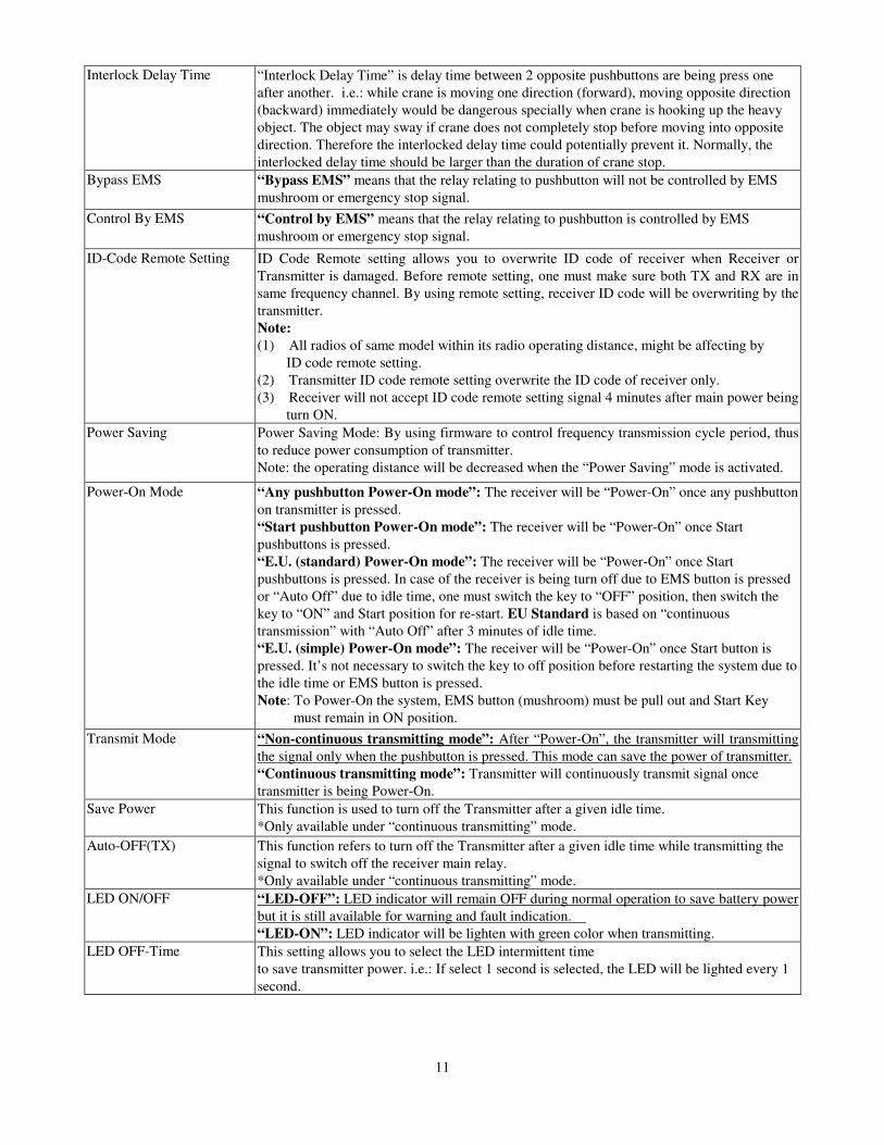
Interlock Delay Time “Interlock Delay Time” is delay time between 2 opposite pushbuttons are being press one after another. i.e.: while crane is moving one direction (forward), moving opposite direction (backward) immediately would be dangerous specially when crane is hooking up the heavy object. The object may sway if crane does not completely stop before moving into opposite direction. Therefore the interlocked delay time could potentially prevent it. Normally, the interlocked delay time should be larger than the duration of crane stop.
Bypass EMS “Bypass EMS” means that the relay relating to pushbutton will not be controlled by EMS mushroom or emergency stop signal.
Control By EMS “Control by EMS” means that the relay relating to pushbutton is controlled by EMS mushroom or emergency stop signal.
ID-Code Remote Setting ID Code Remote setting allows you to overwrite ID code of receiver when Receiver or Transmitter is damaged. Before remote setting, one must make sure both TX and RX are in same frequency channel. By using remote setting, receiver ID code will be overwriting by the transmitter. Note: (1) All radios of same model within its radio operating distance, might be affecting by
ID code remote setting. (2) Transmitter ID code remote setting overwrite the ID code of receiver only. (3) Receiver will not accept ID code remote setting signal 4 minutes after main power being
turn ON. Power Saving Power Saving Mode: By using firmware to control frequency transmission cycle period, thus
to reduce power consumption of transmitter. Note: the operating distance will be decreased when the “Power Saving” mode is activated.
Power-On Mode “Any pushbutton Power-On mode”: The receiver will be “Power-On” once any pushbutton on transmitter is pressed. “Start pushbutton Power-On mode”: The receiver will be “Power-On” once Start pushbuttons is pressed. “E.U. (standard) Power-On mode”: The receiver will be “Power-On” once Start pushbuttons is pressed. In case of the receiver is being turn off due to EMS button is pressed or “Auto Off” due to idle time, one must switch the key to “OFF” position, then switch the key to “ON” and Start position for re-start. EU Standard is based on “continuous transmission” with “Auto Off” after 3 minutes of idle time. “E.U. (simple) Power-On mode”: The receiver will be “Power-On” once Start button is pressed. It’s not necessary to switch the key to off position before restarting the system due to the idle time or EMS button is pressed. Note: To Power-On the system, EMS button (mushroom) must be pull out and Start Key
must remain in ON position. Transmit Mode “Non-continuous transmitting mode”: After “Power-On”, the transmitter will transmitting
the signal only when the pushbutton is pressed. This mode can save the power of transmitter. “Continuous transmitting mode”: Transmitter will continuously transmit signal once transmitter is being Power-On.
Save Power This function is used to turn off the Transmitter after a given idle time. *Only available under “continuous transmitting” mode.
Auto-OFF(TX) This function refers to turn off the Transmitter after a given idle time while transmitting the signal to switch off the receiver main relay. *Only available under “continuous transmitting” mode.
LED ON/OFF
“LED-OFF”: LED indicator will remain OFF during normal operation to save battery power but it is still available for warning and fault indication. “LED-ON”: LED indicator will be lighten with green color when transmitting.
LED OFF-Time This setting allows you to select the LED intermittent time to save transmitter power. i.e.: If select 1 second is selected, the LED will be lighted every 1 second.
12
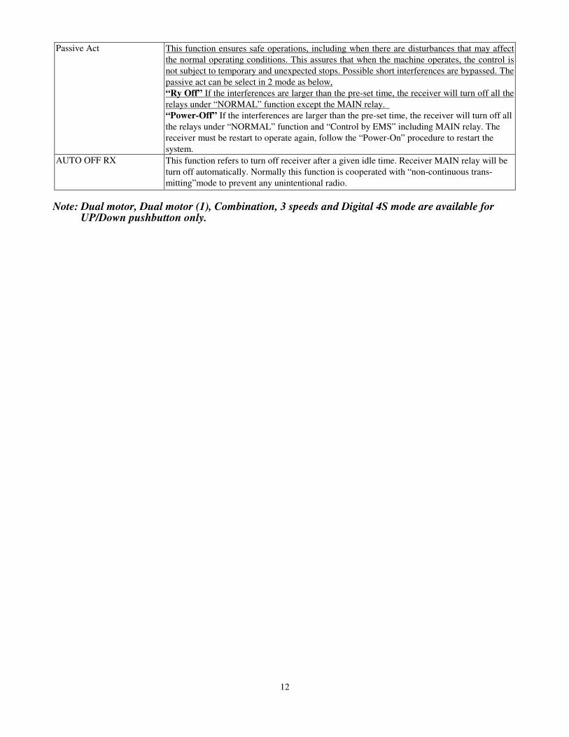
Passive Act This function ensures safe operations, including when there are disturbances that may affect the normal operating conditions. This assures that when the machine operates, the control is not subject to temporary and unexpected stops. Possible short interferences are bypassed. The passive act can be select in 2 mode as below, “Ry Off” If the interferences are larger than the pre-set time, the receiver will turn off all the relays under “NORMAL” function except the MAIN relay. “Power-Off” If the interferences are larger than the pre-set time, the receiver will turn off all the relays under “NORMAL” function and “Control by EMS” including MAIN relay. The receiver must be restart to operate again, follow the “Power-On” procedure to restart the system.
AUTO OFF RX This function refers to turn off receiver after a given idle time. Receiver MAIN relay will be turn off automatically. Normally this function is cooperated with “non-continuous trans- mitting”mode to prevent any unintentional radio.
Note: Dual motor, Dual motor (1), Combination, 3 speeds and Digital 4S mode are available for UP/Down pushbutton only.