Embed Size (px)
Citation preview

7 ADAG88 476 HUGNES AIRCRAFT CO CANOGA PARK CALIF F/6 14/11
PREDICTIVE SOFTWARE COST MODEL STUDY. VOLUME 1. FINAL TECg*ICAL--ETClUlJUN 80 R B WAINA. B L FOREMAN, A P BANGS F3361579--1734
NCLASSIFIED AFWAL-TR-80-156-VOL-1 NL*2ilfllllllll-EEElhllEEliIInnnInIIIInun--- u--iiiii-EIIEEEIIIIE-El---...ii
AFWAL-TR-80-1056Volume I
PRDCTV 1EVEkL00
PREDICTIVE SOFTWARE COST MODEL STUDY
Hughes Aircraft Company j- 0eSupport SystemsCanoga Park, California 91304 -s,
JUNE 1980
VOLUME I: FINAL TECHNICAL REPORTFinal Report for Period 2 April 1979 - 2 June 1980
Approved for Public Release; Distribution Unlimited
C)QAvionics Laboratory
Air Force Wright Aeronautical LaboratoriesLU Air Force Systems Command--J Wright-Patterson Air Force Base. Ohio 45433
80 8 28 022
NOTICE
When Government drawings, specifications, or other data are used for any purposeother than in connection with a definitely related Government procurement operation,the United States Government thereby incurs no responsibility nor any obligationwhatsoever; and the fact that the government may have formulated, furnished, or inany way supplied the said drawings, specifications, or other data, is not to be re-garded by implication or otherwise as in any manner licensing the holder or anyother person or corporation, or conveying any rights or permission to manufactureuse, or sell any patented invention that may in any way be related thereto.
This report has been reviewed by the Office of Public Affairs (ASD/PA) and isreleasable to the National Technical Information Service (NTIS). At NTIS, it willbe available to the general public, including foreign nations.
This technical report has been reviewed and is approved for publication.
DANIEL V. FERENS DIANE E. SUMMERS, Tech MgrWork Unit Engineer Concepts and Evaluation GroupAFWAL/AAAS-2 System Integration Branch
FOR THE COMMANDER
RAYMOND E. SIFERD, Colonel, USAFChief, System Avionics DivisionAvionics Laboratory
"If your address has changed, if you wish to be removed from our mailing list, or
if the addressee is no longer employed by your organization please notify AjAL ,W-PAFB, OH 45433 to help us maintain a current mailing list".
Copies of this report should not be returned unless return is required by securityconsiderations, contractual obligations, or notice on a specific document.
AIR FORCE/56780/28 July 1980 - 100
SECURITY CLASSIFICATION OF THIS PAGE (When D1t Enlered) ,__
qEPORT DOCUMENTATION PAGE READ INSTRUCTIONSBEFORE COMPLETING FORM
H6-OR- NUMBER 2. GOVT ACCESSON NO. 3. RECIPIENT'S CATALOG NUMBER
j) AFWAITR-80-lO56, Vol. I ~ A{.4D~4. TITLE (and Subtitle) S. TYPE OF REPORT & PERIOD COVERED-........ Final ReportS .REDICTIVE .OFTWARE LOST XODEL 9TUDY, 2 April 1979 to 2 June 1980Volume 'Tinal Tec"Sical Report' o 6. PERFORMING ORG. REPORT NUMBER
7. AUTHOR(*) R.B. Waina E... Rfrluel') /
G.L. Foreman E.E. Rodriguez 33615-79-C-1734 / .'A.P. Bangs P33615J.L. Green
9. PERFORMING ORGANIZATION NAME AND ADDRES,-".......... I..0. PROGRAM ELEMENT, PROJECT SK; ki" Huges ircaft ompny ' / / /AREA 6WORK UNIT NUMBFR1//u sAircraft Company P. E. 62204F
Project 2003, Task/_ 09,Canoga Park, California 91304 Work Unit 20030913
I 1. OTRILL'Nfa YO FICF NE Irc)D S.,.,---kv n cs ry ol Ar rce Wright Aero-
nautical Laboratories (AFWAL/AAA)Air Force Systems CommandWright-Patterson AFB, Ohio 45433 182
'1_MMTBL)4 AGEN V-N1AM" ADQR4.&SWd dSUte..,4.*.Cntollnt Office) 1S. SECURITY CLASS. (of this reort)I4 /F t' J 4 , / POP Unclassified- ',. , , T " 76r , L. , Q, -. IS. OECLASSIFICATIONDOWNGRAOING;.ck "v .1 _'' e'. .. . SCHEDULE
S. O $TR IBUTION/M f, MEh 4 . . . ...s. u.t
Approved for public release; distribution unlimited.
1r7. DISTRIBUTION STATEMENT (of the abstr'act entered In Block 20, It different fro. Report)
IS. SUPPLEMENTARY NOTES
This technical report is also composed of Volume II, Software PackageDetailed Data.
11. KEY WORDS (Continue on reverse aide If necessary and Identify by block number)
Software Support Cost EffectivenessEmbedded Computer Systems
Avionics SupportLife Cycle Cost
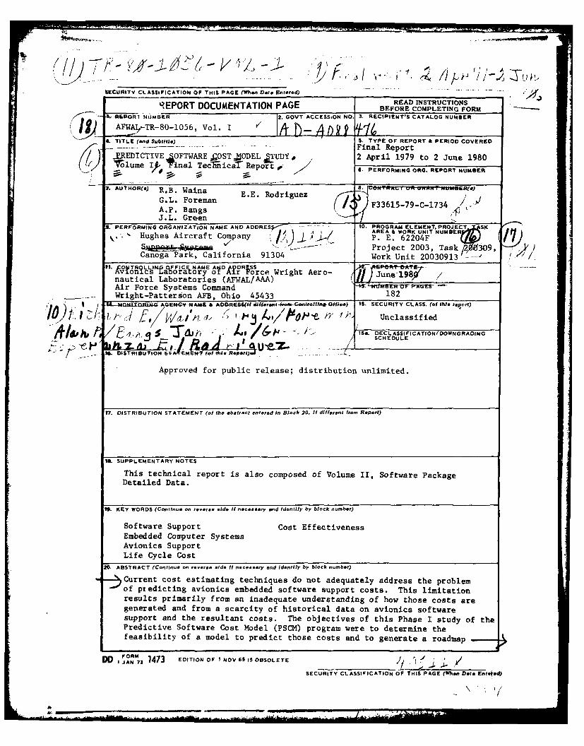
20. ABSTRACT (Continue on revere side If necessery and Identify by block number)
Current cost estimating techniques do not adequately address the problemof predicting avionics embedded software support costs. This limitationresults primarily from an inadequate understanding of how those costs aregenerated and from a scarcity of historical data on avionics softwaresupport and the resultant costs. The objectives of this Phase I study of thePredictive Software Cost Model (PSCM) program were to determine thefeasibility of a model to predict those costs and to generate a roadmap
DO 1JAN 73 1473 EDITION OF I NOV SS IS OBSOLETE- .. * '
SECURITY CLASSIFICATION OF THIS PAGE (Whon Date Enled)

,9for development of such a model. The feasibility of such a model wasestablished. It will include the six key resource types required tosupport avionics software: personnel, support hardware, support soft-ware, facilities (buildings), program documentation and flight testaircraft/ranges. Some preliminary estimating relationships were iden-tified. A detailed roadmap for developing the model was generated. PhaseII of the PSCM program will provide an operating model for predictingavionics embedded software support costs.

PREFACE
The Predictive Software Cost Model Study Phase I TechnicalReport is prepared in two separately bound volumes.
Volume I - Final Technical Report
Volume II - Software Package Detailed Data
The Air Force Program Monitor was Mr. Daniel V. Ferens,Systems Evaluation Group, Avionics Systems Engineering Branch(AFWAL/AAAA-3).
TOT-
iDis

SUMMARY
The Avionics Laboratory of the Air Force Wright AeronauticalLaboratories (AFWAL/AA) has identified a requirement to predictsupport costs of avionics embedded computer system software.The requirement, further, is to be able to predict the softwarecosts early in an advanced avionics system program during thedevelopment planning processes. The desire is to be able toevaluate alternate software and software support concepts earlyenough in their life cycles in order to influence the software,and perhaps hardware, designs to achieve required performance(s)at lowest life cycle cost.
The requirement can be satisfied by an appropriatepredictive model. The question was whether such a modelexisted. If so, is it adequate? If not, can one be developed?AFWAL/AA initiated a two-phase Predictive Software Cost Model(PSCM) study program by means of RFP No. F33615-79-R-1734.Efforts and results of Phase I of the study program are thesubject of this report.
The objective of Phase I of the study was to define themethodology for developing a model which will enable AFWAL/AApersonnel to predict the support costs of computer softwareassociated with avionics systems. The approach taken addressedtwo major elements inherent in the objective: establishing thefeasibility of developing the desired model and, having doneso, defining the methodology for model development in the formof a roadmap for conduct of Phase II of the PSCM program. Theessence of the approach encompassed: 1) identifying andevaluating current and proposed practices regarding softwaresupport performance and cost estimating, 2) assessingavailability of historical software support data, 3) determiningfeasibility of designing a software support cost prediction modelbased on available data, and 4) generating a methodology, i.e.,a detailed roadmap, for Phase II model development.
The first step of the study was to establish the feasibilityof designing a credible model that will predict software supportcosts with acceptable accuracy. To accomplish this, informationwas gathered and evaluated to determine whether availablehistorical and other supplemental data is adequate as the basisfor a predictive model design. The evaluation proved that apredictive software support cost model design is- indeed,feasible.
Given feasibility, the second step was to define themethodology for developing the model in the form of. a detailedroadmap to guide the model design during Phase II of the program.
Establishing model feasibility included several phases:1) a technology review, 2) field surveys and 3) an analysis
of findings.
v

Technology review assessed the current state of softwarecost estimating from the standpoint of relevant literature aswell as existing software cost prediction models. Numerousstudies, reports, journals and periodicals were researched toidentify and assess various cost estimating techniques,significant cost drivers, typical cost distributions, possibleparameter/cost relationships, and possible data sources. Theassessment of relevance to avionics embedded software supportcost estimation gave direction to subsequent efforts. Also,twenty-one software cost prediction models were examined' toidentify commonalities and differences in cost estimatingapproaches. Results showed that adequate prediction models existfor software development costs. but not for software supportcosts. A main problem was the lack of historical softwaresupport data and good metrics for software quality, reliabilityand maintainability.
The total complement of Air Force avionics software isestimated to number more than 50,000 separate pieces. Theyare generally categorized as: 1) operational flight programs(OFPs), 2) electronic warfare (EW) programs, 3) communicationelectronics (CE),3 including airborne command, control, andcommunications (C ) programs, 4) aircrew training device (ATD)programs, and 5) automatic test equipment (ATE) programs.
Field surveys were conducted to determine current processesof avionics embedded software support within the Air Force, andhow these processes interact with and affect resultant softwaresupport costs. A team of contractor personnel visited each AirLogistics Center, interviewed key software support personnel,and collected data on six major relevant sample softwarepackages: 1) A-7D OFP, 2) F-111F OFPs, 3) FB-111A OFPs, 4)F/FB-lII Support Software, 5) F-15 OFPs, and 6) F-16 OFPs.Limited data was also collected in the EW and ATE areas, andadditional data sources were identified.
An analysis of findings from the technology review and fieldsurveys was performed to assess the key factors affectingavionics embedded software support costs. Results revealed sixprimary resource categories to be considered in the model design:1) personnel, 2) support equipment, 3) support software, 4)facilities, 5) data and documentation, and 6) flight test. Theprimary support cost drivers of these resource categories weredetermined to be: 1) change requirements, both frequency andsize, 2) prime system software, including program size,architecture, and hardware constraints, 3) prime system hardware,4) software support personnel, including experience, trainingand productivity, and 5) test requirements for software changes.
Findings also indicated, from the data sample and theidentification of additional available software supportperformance data, that adequate data of sufficient quality areavailable upon which to design a predictive software cost modelthat emphasizes software support costs.
vi

To define the model roadmap, several alternate modellingapproaches for developing the predictive software cost modelusing the available data were evaluated and the best alternativewas selected. The recommmended approach defines a methodologywhich embodies five fundamental tasks: 1) collect (additional)data, 2) analyze all data, both quantitatively and qualitatively,3) develop a data base that will be interfaced automaticallyby the model, 4) design the predictive software cost model usingboth statistical and qualitative analysis techniques, and 5)perform verification and validation testing of the model design.The methodology is presented in the form of a detailed roadmapfor conducting the Phase II model development. Upon completionof model design, provision is made for installing the model inthe host computer at Wright Patterson Air Force Base, and fortraining programmer and user personnel.
A preliminary estimate of resource requirements forperforming Phase II efforts showed slightly more than 4.5personyears of engineering labor plus associated clerical, traveland computing costs.
Primary risks in conducting Phase II in accordance withthe recommended methodology center about three areas: 1) qualityand quantity of available data being less than expected, 2)constraints on model usage imposed by the design approach whichprovides ease of use by means of minimum input requirements,and 3) model misuse. These risks, however, are not peculiarto the recommended approach; they are risks for any modeldevelopment approach.
vii
PREFACE TO VOLUME I
This final report was prepared by Support Systems of HughesAircraft Company at Canoga Park, California 91304. This studyexamined the feasibility of predicting avionics embedded softwaresupport costs and generated a roadmap for developing a modelto predict such costs. The program began with contract go-aheadon 2 April 1979 and was completed on 2 June 1980.
Mr. Daniel V. Ferens was the Project Engineer from theAvionics Laboratory of the Air Force Wright AeronauticalLaboratories (AFWAL/AA). Under his direction and with thecooperation of Ms. Diane Summers and the personnel of the AirForce Logistics Command located at Tinker AFB, Oklahoma; ChinaLake Naval Weapons Center, California; McClellan AFB, California;Robins AFB, Georgia; Hill AFB, Utah; and Kelly AFB, Texas, the
L necessary data on Air Force Support of avionics embedded computersystem software were gathered for this study.
The Support Systems and Maintainability EngineeringLaboratory under the management of Mr. Robert W. Rowe wasresponsible for program execution. The program manager was Mr.Ercell C. Hamilton. Dr. Richard B. Waina was the principalinvestigator. He was ably assisted by Mr. Alan P. Bangs, Mr.Gary L. Foreman and Ms. Esperanza E. Rodriguez. Messrs. JamesL. Green and Russell A. Vande Steeg provided additional supportwhich contributed to the overall success and content of thisreport.
viii

........ ------ ----
, -
) '~- -

TABLE OF CONTENTS
SECTION PAGE
I. INTRODUCTION 1
II. BACKGROUND 3
Objectives of Study 3Scope of Study 3Organization of Report 4
III. TECHNICAL APPROACH 5
General Approach 5Task I: Software Cost Estimating Approach Review 7Task II: Field Surveys 8
Software Package Identification 8Software Package Selection 8Software Support Site Visitation 11
Task III: Data Analysis 12Identification of Support CoSt Drivers 13Evaluation of Software Support CostPrediction Feasibility 13
Alternate Approach Formulation 14Approach Evaluation 14Approach Selection 14
Task IV: Model Roadmap Development and Evaluation 14
IV. SURVEY OF CURRENT APPROACHES IN SOFTWARE COST 17ESTIMATING
Introduction 17Cost Models 17Cost Drivers as Perceived by Modellers 21Validity of Cost Models 23Conclusions 27
V. FIELD SURVEY FINDINGS 29
Software Population 29Air Force Inventory Systems 29PSCM Study Software Inventory 30
Software Sample 30A-7D OFP 34F-15 OFPs 34F-16 OFPs 34F-1l1A and F-111F OFPs 36F/FB-11 Suppore Software 36
The Software Life Cycle 36Comparison of Hardware and Software 36The Computer Program Life Cycle 38
ix

- --------
TABLE OF CONTENTS (Continued)
SECTION PAGE
V Computer Resources Integrated Support Plan 40(cont) Causes of Software Modifications 41
The AFLC Resource-Level Planning Process 42The AFLC Software Support Process 44
General Description of the Support Process 44Data Collection Systems 55OFP Support at OC-ALC/China Lake 57OFP Support at SM-ALC 58OFP Support at 00-ALC 59OFP Support at WR-ALC 60EW Support 61ATE Software Support 63General Observations 64
VI. ANALYSIS OF DATA AND COST DRIVERS 65
General Software Support Data 65Manhour and Change Data 68Flying Hour Cost Factors 73Software Package Quality 74What Do the Experts Say? 74Support Cost Generation 76Personnel 76Support Hardware/Software and Facilities 79Documentation 80Aircraft Flight Test 80
Conclusions 80
VII. FEASIBILITY OF ESTIMATING SOFTWARE SUPPORT COSTS 83
Introduction 83Purpose/Use of Desired Model 83Cost Estimating Approaches 84
Analogy 84Element Estimate 85Cost Estimating Relationship (CER) 85Hybrid 85
Ranking Cost Estimating Approaches 85Evaluation Criteria 86Performance Assessment 89Utility Value Assessments 89Weighted Average Scores of Approaches 92
Conclusions 95
VIII. DEFINITION OF PHASE II ROADMAP 97
General 97Collect Data 101
Data Types 101Data Required 103
x

TABLE OF CONTENTS (Continued)
SECTION PAGE
VIII Analyze Data 111(cont) Paramater/Parameteric Relationship
Determination 113Develop Data Base 114
Preliminary Data "Working Files" 116"Processed Data" Files 116Operational Data Base 117Data Base Concept Summary 117
Design PSC Model 117Algorithm Development 118Model Structure Design 119Model Automation Implementation 121
Test PSC Model 122Model Verification 122Model Validation 122
Deliver Final PSC Model 124Installation 124
Documentation 124Training 124
Estimate of Resource Requirements For Phase II 125Collect Data 125Analyze Data 126Develop Data Base 126Design PSC Model 127Test PSC Model 127Deliver PSC Model 127Resource Requirements Summary 128
Phase II Risks 128Data Risks 130Approach Risks 130Model Usage Risks 131
IX. CONCLUSIONS 133
X. OBSERVATIONS AND RECOMMENDATIONS 137
Observations 137Recommendations 137
BIBLIOGRAPHY 139
APPENDICES
A. DESCRIPTION OF CPIN SYSTEM 151
B. TYPICAL POSITION DESCRIPTION OF AISF PERSONNEL 161DEVELOPING AND INTEGRATING SOFTWARE CHANGES
LIST OF ACRONYMS 165
xi

LIST OF ILLUSTRATIONS
FIGURE PAGE
1. Predictive Software Cost Model Study Approach 6
2. Predictive Software Cost Model Study Process 9
3. Actual Versus Predicted Manning Levels 26
4. Computer Program Life Cycle 39
5. Avionics Integration Support Facility 47
6. OFP Change Process 49
7. OFP Change Cycle 50
8. OFP Configuration Control Documents 54
9. OO-ALC Project Accounting and Control Report 56
10. EW Integration Support Station 63
11. F/FB-III Change History 70
12. F/FB-lII Manhours per Change 70
13. A-7D Change History 72
14. A-7D Manhours per Change 72
15. Software Support Cost Generation 78
16. Basic Utility Curves 91
17. Utility Assessments for Evaluation Criteria 93
18. Model Development Methodology 98
19. Model Development Roadmap 99
20. Data Type Relationships 103
21. Data Base Development Concept 114
22. Basic Data Flow 121
xii

LIST OF TABLES
TABLE PAGE
1. AFWAL/AA Predictive LCC Models 1
2. Software Development and Support Cost 18Prediction Models
3. Cost Model Factors 22
4. Cost Factors Accounted for by PRICE-S2 24
5. Results of Cost Model Study 25
6. OFP Software Systems 31
7. EW Software Systems, WR-ALC 31
8. ATE Software Systems, SA-ALC 32
9. Sample Software Package Descriptions 33
10. AISF Support Objectives 46
11. Navigation Systems Support, OC-ALC 57
12. SM-ALC/MMECP Staffing 59
13. OO-ALC OFP Support 60
14. OO-ALC F-16 Computing Support Equipment 60
15. EW Systems 62
16. ALCs and Sample Systems 65
17. ALC-Related Data 66
18. Sample Package Data 67
19. Composite Change History 68
20. Analysis of F/FB-11 Manhours 69
21. F/FB-1I Block Change Data 71
22. A-7D Block Change Data 71
23. Aircraft Flying-Hour Cost Factors 73
xiii

LIST OF TABLES (Continued)
TABLE PAGE
24. Package Quality Ratings 74
25. Factors Considered Important by ALC Personnel 75
26. Major Cost Categories and Drivers 77
27. PSCM Evaluation Criteria Suggested by AFWAL/AA 87
28. Weighting of Evaluation Criteria 88
29. Cost Estimating Approach Performance Assessments 90
30. Cost Estimating Approach Evaluation 94
31. Data Required - Conceptual 104
32. Data Required - Regulatory 105
33. Data Required - Procedural 107
34. Data Required - Performance 109
35. Data Required - Performance Relationships 110
36. Special Data 111
37. Phase II Resource Requirement Estimate 129
I
xiv

I. INTRODUCTION
There have been spectacular advances in computertechnologies applied in Air Force avionics systems and subsystemsin recent years. Since software (i.e., computer programs) isan increasingly significant component of these avionics systems,there have been dramatic rises in the costs of developing andsupporting the associated computer software. Accordingly, theAvionics Laboratory of the Air Force Wright AeronauticalLaboratories (AFWAL/AA) and the Air Force in general need to beable to predict the software costs in planning the developmentof advanced avionics systems.
Software life cycle cost estimating is hampered, however,by a lack of definitive historical data on software operationand support and the associated costs. Also, there isinsufficient understanding of the factors that drive andotherwise affect those costs. Although there is some knowledgeof cost distributions, and some feel for what the significantcost drivers are, there is no widely-accepted well-validatedmodel for early estimation of avionics embedded software supportcosts.
There are several models and cost-estimating approachesused by AFWAL/AA to estimate costs of computer hardware andsoftware (see Table 1); however, none of the models or approachespredicts support costs of avionics software to a sufficientdegree of accuracy, nor adequately takes into account the effectsof various developmental phase concepts on cost-of-ownershipof avionics software. The models also do not satisfactorilyaddress support policies and operational and support softwarerequirements for avionics systems.
TABLE 1. AFWAL/AA PREDICTIVE LCC MODELS
Hardware Software
Development/ PRICE-H PRICE-SProduction WOLVERTON
ALPOSOperation & PRICE-L ? ? ?Support SAVE
STEP
1!

AFWAL/AA needs software support cost predictions to:
* Evaluate software design alternatives (e.g., higher-order
versus machine language)
* Evaluate software support concept alternatives (e.g.,in-house versus contractor support)
* Make total software support cost projections for DSARCand preliminary budget planning purposes.
These cost predictions must have an acceptable degree of accuracyand must be available in a timely manner during the conceptualand early design phases for effective conduct of cost-performancetradeoffs. In order to acquire this capability AFWAL/AAinitiated the Predictive Software Cost Model Program in twophases. Phase I was to study the feasibility of such a model,and generate a roadmap for its development. Phase II will resultin an operational model.
2
II. BACKGROUND
OBJECTIVES OF STUDY
Phase I of the Predictive Software Cost Model (PSCM) programhas two major objectives:
(1) to establish the feasibility of developing a model whichwill enable AFWAL/AA personnel to predict the supportcosts of embedded computer software associated withavionics systems and subsystems,
(2) to define the methodology for model development in theform of a roadmap for conduct of Phase II of the PSCMprogram.
SCOPE OF STUDY
The scope of this study was limited to the area of supportcosts for avionics embedded software. Although the contractualstatement of work referred to "operations and support costs,"it was determined that operations costs for avionics embeddedsoftware are basically non-existent, being subsumed underhardware costs. The Phase I study addressed the following tasks:
* Review of existing software cost estimating capabilities,
including models.
* Field surveys of avionics embedded software supportfacilities to identify software packages, to developan understanding of software support policies andprocedures, and to collect sample historical data.
Analysis of the collected data to determine modelfeasibility, identify support cost drivers, evaluatealternate cost estimating approaches, and select thebest approach.
* Definition of a methodology in the form of a roadmapfor developing an avionics software support costestimating model based on the selected approach.
Although prediction of software development costs is notdirectly included in the scope of the PSCM program, the effectof certain developmental phase concepts such as structuredprogramming, top-down design and higher-order language utiliza-tion in software support cost estimation were considered.
3

ORGANIZATION OF THE REPORT
The above tasks are discussed in more detail in subsequentsections of this report, which is organized as follows:
Section III, Technical Approach, describes the methodologyused in this phase to determine the feasibility ofpredicting avionics embedded software support costs. Italso describes the approach to defining a roadmap fordevelopment of a model to predict those costs.
Section IV, Survey of Current Approaches in Software CostEstimating, relates the findings resulting from the reviewof software cost estimating technology and knowledge.
Section V, Field Survey Findings, describes the datacollected from the various Air Logistics Centers(ALCs). Both software packages and software supportpolicies and procedures are discussed.
Section VI, Analysis of Data and Cost Drivers, discussessignificant factors which must be considered in costestimating, based on the results of the literature searchand field surveys.
Section VII, Feasibility of Estimating Software SupportCosts, establishes feasibility, defines and evaluatesalternate approaches to cost estimating, and identifiesthe selected approach.
Section VIII, Definition of Phase II Roadmap, details amethodology for developing a model to predict avionicsembedded software support costs.
Section IX, Conclusions, presents the major conclusionsresulting from the study.
Section X, Observations and Recommendations, containsobservations made during the course of the field surveyswhich relate to the overall efficiency of the avionicssoftware support process. Recommendations are alsoprovided.
Volume I of this report contains the detailed data onsoftware support agencies and sample software packageswhich were gathered during the field surveys.
4

III. TECHNICAL APPROACH
This section describes the procedures used in conductingthe study. The results of the study are described in latersections.
GENERAL APPROACH
This study has two major objectives: 1) establish thefeasibility of predicting avionics embedded software supportcosts and 2) define a methodology to develop the PredictiveSoftware Cost Model. The study objectives were met by applyinga systems approach similar to other system engineering efforts.The approach included:
* Examination of the requirement
* Study of current technology/processes
* Definition of candidate solutions/systems
* Evaluation of alternate approaches
* Selection of the alternative which best satisfied therequirement
* Development of a roadmap for the selected approach
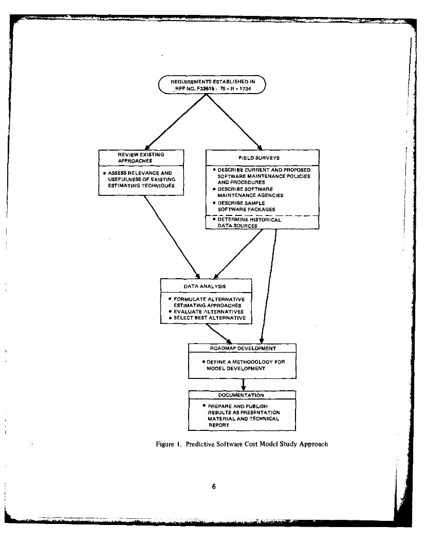
The application of this approach to the problem is illustratedin Figure 1, which identifies the basic tasks performed.
The requirement for a model to predict avionics embeddedsoftware support costs was delineated in RFP #F33615-79-R-1734.This requirement was discussed in greater detail in the initialmeeting with AFWAL/AA in order to assure mutual understandingof the objectives of the study.
The initial task in the study was to investigate the currenttechnology of software cost estimating. This first task involveda review of existing cost estimating approaches and an assessmentof their relevance and usefulness to the job of predictingavionics embedded software support costs.
Field surveys were then performed to determine currentprocesses of avionics embedded software support within the AirForce, and how those processes interact with and affect theresultant software support costs. Data on particular samplesoftware packages were acquired as part of the surveys. Sourcesof historical data on software support were also identified.
The data resulting from the first two tasks were then anal-yzed to determine key factors affecting avionics embedded
REQUIREMENTS ESTABLISHED INRFP NO. F33615 - 79 - R - 1734
REVIEW EXISTING FIELD SURVEYSAPPROACHES
ASSES RELVANCEAND DESCRIBE CURRENT AND PROPOSED0 ASSESS RELEVANCE AND
SOFTWARE MAINTENANCE POLICIESUSEFULNESS OF EXISTING ADPOEUEAND PROCEDURES
ESTIMATING TECHNIQUES * DESCRIBE SOFTWARE
MAINTENANCE AGENCIES* DESCRIBE SAMPLE
SOFTWARE PACKAGES
SDETERMINE HISTORICALDATA SOURCES
DATA ANALYSIS
" FORMULATE ALTERNATIVEESTIMATING APPROACHES
" EVALUATE ALTERNATIVES" SELECT BEST ALTERNATIVE
ROADMAP DEVELOPMENT
•DEFINE A METHODOLOGY FORMODEL DEVELOPMENT
DOCUMENTATION
* PREPARE AND PUBLISHRESULTS AS PRESENTATIONMATERIAL AND TECHNICALREPORT
Figure 1. Predictive Software Cost Model Study Approach
6J

software support costs. The feasibility of predicting thosecosts was determined. Various approaches to estimating softwaresupport costs were formulated and evaluated according to criteriaestablished by AFWAL/AA and Hughes. The best approach wasidentified and a roadmap was then prepared for development ofa PSCM based on that approach.
The actual execution of this approach was aided throughinputs from three recent Hughes studies: 1) Software Logistics,2) Software Cost Factors, and 3) Design-For-Repair ConceptDefinition. An on-going Software Logistics study providedbackground data on software support processes and cost estimatingtechnology. An IR&D study on Software Cost Factors providedinsight into software cost distribution and cost drivers.Experience gained conducting field surveys during theDesign-For-Repair Concept Definition study helped to make thefield surveys for this study more efficient and productive.
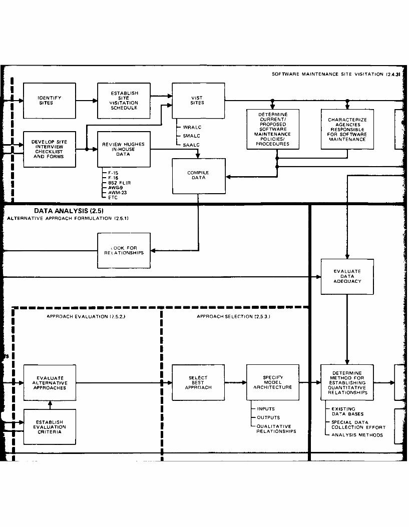
A detailed flow of the methodology used to conduct PhaseI of the PSCM study is described in Figure 2. This flow diagramis the focal point for subsequent discussion of the technicalapproach; it delineates the complexity and scope of the effort.
TASK I: SOFTWARE COST ESTIMATING APPROACH REVIEW
The review of software cost estimating approaches startedwith a literature search, as indicated in Figure 2. This searchutilized sources such as the Defense Logistics Studies Informa-tion Exchange and the Defense Documentation Center. Applicablestudies and reports were researched, as were various journals andperiodicals such as Datamation, Computer, and IEE Trans-actions on Software Engineering. Proceedings o variousconferences and symposia were also reviewed. The bibliographycontained in this report identifies the articles and studiesreviewed. The objective of the literature search was to identify:
* Various cost estimating techniques
* Significant cost drivers
* Typical cost distributions
* Possible relationships between various parameters and cost
* Possible data sources
Data extracted from the articles and studies were compiledand cost estimating approaches identified. The relevance ofthe data and cost estimating approaches to avionics embeddedsoftware support cost estimation was also assessed. This assess-ment gave some indication of the direction to be taken indeveloping an avionics software support cost estimating model.The results of this review are documented in Section IV.
7

TASK II: FIELD SURVEYS
A major portion of this study was devoted to field surveysfor collection of data on avionics embedded software support.The survey phase involved three subtasks:
• Software package identification
• Software package selection
• Software maintenance site visitation
Software Package Identification
This task was to identify avionics software packages withinthe Air Force inventory of weapons systems. The Air Forcecategorizes embedded computer system (ECS) software as follows:
" Operational flight programs (OFPs)
" Electronic warfare (EW) programs
" Communication electronics (CE), including airbornecommand, control, & communication (C ) programs
" Aircrew training device (ATD) programs
" Automatic test equipment (ATE) programs
AFWAL/AA and Hughes decided to concentrate the major effort inthis study on OFPs, while collecting some data on EW and ATEsoftware support processes. This plan offered the mostcost-effective approach to developing a software support costmodel roadmap.
Software Package Selection
Hughes identified a representative sample of softwarepackages for detailed study. Individual package characteristicssuch as program language, application, maintaining agency andresponsible ALC were first considered. Candidates were nominatedfrom those identified. These candidates were then discussedwith AFWAL/AA at the Software Selection Conference. Selectionof six packages was approved by the AFWAL/AA Program Manager.These were:
• A-7D OFP
• F-111F OFPs
• FB-111A OFPs
• F/FB-111 Support Software
8

SOFTWARE PACKAGE IDENTIFIjATION (2.4.1
COMPILE LIST IDENTIFIDENTIFO VISIT SYSTEM TECHNICAL OF AVIONICS SOFTWA
AVIONICS AL- SAAND OTHER SOFTWARE PACKAGSOTAEASD OMETO PACKAGES U CHARACTERPACKAGES DOCUMENTATION
-15 (WRALC) LANGUAGI
-- FB.11 (SMALC) APPLICATI
C-5A (SAALC) MAINTAIN(* AGENCY
II
SOFTWARE COST ESTIMATING APPROACH REVIEW
SELECT REVIEW SELECTSUBJECT LITERATURE. LITERATURE APPLICABLE SECURE
DESCRIPTORS SEARCH SEARCH DOCUMENTS iOCUMENTS
DEFENSE PRIMARYDOCUMENT CENTER SECONDARY
NSIA DOCUMENTCENTER
DEFENSE LOGISTICSSTUDIES INFORMATIONEXCHANGE
E-HUGHES STUDIES
PERIODICALS, BOOKS, ETC
ESTABLISHDOCUMENT
EVALUATIONCRITERIA
-I)ESCRIPTION OF COST ESTIMATING TECHNIQUES
IDENTIFICATION OF COST DRIVERS
ANALYSIS OF COST DISTRIBUTIONS
ANALYSIS CF PARAMETER RELATIONSHIPS
II)i NTIFICATION OF DATA SOURCES

;IEW (2.3) A,
DEFINEMODE L
PURPOSE
COMPILE ASSESS USEFUL- *1REVIEW DATA ON NESS'RELEVANCE DETERMINE
DOCUMENTS EXISTING TO AVIONICS ARIMETAL
TECHNIQUES SOF TWARE
DETERMINE DEVELOPQUALITATIVE GROSS MODEL
RELATIONSHIPS SPECIFICATION
INPUTS
.- OUTPUTS
FORMU LATEALTERNATIVE
APPROACHES
SOFTWARE MAINTENANCE SITE VISITATION (2.4.31|I ESTABLISH
IDENTIFY SITE VISTSITES VISITATION SITES
SCHEDULE
* DETERMINECURRENT/ CHARACTERIZE
*PROPOSED AGENCIES- WRALC SOFTWARE RESPONSIBLESMALCMAINTENANCE FOR SOFTWARE
DEVELOP POLICIES/ MAINTENANCEINTERVIEW REVIEW HUGHES SAALC PROCEDURES
CHECKLIST IN-HOUSE
AND FORMS DATA
F-15 COMPILE___________ F- 16 DATA
TB52 FLIR-AWG-9-AWM-23
!- ETC
DATA ANALYSIS (2.5)ALTERNATIVE APPROACH FORMULATION (2.5.1)
, OOK FORRELATIONSHIPS
EVALUATEDATA
ADEQUACY
APPROACH EVALUATION 2.5.2.) APPROACH SELECTION !2.53.)
II
EVALUATE SELECT SPECIF'Y METHOD FORALTERNATIVE oil BEST MODEL ESTABLISHINGU APPROACHES APOC RHTCUEQATTTV
IDA'A BASES
ESTABLISH OTUS-SPECIAL DATAEVALUATION - QUALITATIVE COLLECTION EFFORT*
CRITERIA RELATIONSHIPS AAYI EHD
SANAYISMTHD

COST MODEL ROADMAP DEVELOPMENTAND EVALUATION (2.6)
EVALUATEDATA
ADEQUACY
DETERMINE FORMULATE ASSESS RISK OF DOCUMENTMETHOD FOR PLAN FOR DEVELOPMENT STUDY FINAL
ESTABLISHING DEVELOPING AND EXPECTED RESULTS IN REPORT
QUANTITATIVE INITIAL ACCURACY FINAL REPORTRELATIONSHIPS MODEL OF MODEL
-EXISTING
DATA BASES
FORMULATE-SPECIAL DATA PLAN FOR
COLLECTION EFFORT REFINING
ANALYSIS METHODS MODEL

* F-16 OFPs
* F-15 OFPs
In addition to these software packages, AFWAL/AA and Hughes decidedthat preliminary information should be collected regarding EW andATE software support.
Software Support Site Visitation
The particular sites to be visited were based on supportresponsibility for the software. Support sites were:
Software Support Site Packages
Oklahoma City ALC (OC-ALC) A-7D
China Lake NWC (OC-ALC/MMECZA) A-7D
Sacramento ALC (SM-ALC) F/FB-III
Warner-Robins ALC (WR-ALC) F-15, EW, ATE
Ogden ALC (OO-ALC) F-16
San Antonio ALC (SA-ALC) ATE
Once the sites were selected a base visitation schedule wasprepared and coordinated with AFWAL/AA. The final visit schedulewas also coordinated with AFLC and the selected bases to ensureavailability of cognizant personnel.
Four major data collection objectives were established forthe site visits:
* Determine current and proposed software maintenancepolicies and procedures
* Identify software maintenance agencies
* Define characteristics of the sample software packages
* Identify sources of historical data on software
maintenance actions and costs.
Data were collected at the maintenance sites using a struct-ered interview process. Field evaluation forms specificallydesigned for this study were used to provide a structured setof questions covering desired aspects of avionics embeddedsoftware support. These questions were presented by theinterviewer who then annotated the interviewee's responses, bothspecific and general, on the forms. Various regulations andprocedures were also reviewed. The basic categories ofinformation gathered were:
11
* General Software Package Description
* Maintenance Agency Personnel
* Maintenance Agency - Work Distribution
* Maintenance Agency - Cost Accounting System
* Maintenance Agency - Policies & Procedures I* Personnel Description
* Software Package Characteristics -FacilitiesBuildingsComputing Equipment
* Software Package Characteristics - Support Software
* Software Package Characteristics - Flight Test Requirement
* Software Package Characteristics - Training Requirements
" Software Package Maintenance History
* Software Package Maintenance Cost History
* Availability and Sources of Historical Data
* Recommendations for Software Support Cost Predicting
The completed forms for each sample package, plus informationon EW and ATE support, are included as Appendixes A through H ofVolume Ei of this report. The basic findings of the fieldsurvey, including discussion of software population and tite studysample, and description of the software life cycle and sortwaresupport processes, are prese-nted in Section V.
TASK III: DATA ANALYSIS
The data analysis phase involved five major subtasks:
* Identification of support cost drivers
* Evaluation of software support cost prediction
feasibility
* Alternative approach formulation
* Approach evaluation
* Approach selection
12

Identification of Support Cost Drivers
A key element in the study was the identification ofcritical parameters which have major influence on softwaresupport costs. Factors affecting this task included:
* Relevance of current estimating approaches to avionicsembedded software
* Detailed definition of model purpose
* Analysis of field survey data
In Task I, Software Cost Estimating Approach Review, theusefulness and relevance of current software cost estimatingapproaches to the problem of estimating avionics embeddedsoftware support costs were assessed. Critical parametersidentified in that review are discussed in Section IV.
The purpose and proposed use of the Predictive SoftwareCost Model were reviewed at the Software Selection Conference.Consideration of the decision-making needs of the model usershelped determine the critical parameters. The model is to beused primarily to assess the support cost impacts of variousalternative avionics embedded software designs and supportpostures.
During the field surveys detailed data were gathered onsoftware support policies, software support agencies, andspecific software packages. Those data were analyzed to determinewhat variables have the greatest impact on support costs, andwhat the qualitative relationships are.
A preliminary model specification was developed based upondetermination of the critical parameters as they relate to themodel purpose, required outputs, and inputs.
The results of this analysis task are discussed in SectionVI.
Evaluation of Software Support Cost Prediction Feasibility
The feasibility of implementing a cost estimating procedureis based on three elements:
* An understanding of the process by which those costsare generated.
* The availability of historical data describing theprocess.
13
. . ......

The development of an approach which considers a) thepurpose and use of the estimating procedure, b) the inputdata available at the time when the procedure is to beused, and c) estimating algorithms which reflect thecost generation process.
These elements were evaluated in parallel with the process ofidentifying cost drivers and analyzing estimating approaches.The feasibility of estimating avionics embedded software supportcosts is discussed in Section VII.
Alternate Approach Formulation
The next task was to formulate alternative software supportcost estimating approaches. Three basic approaches were invest-igated:
* Analogy
* Element estimate
* Cost estimating relationship
Those approaches are described in Section VII.
Approach Evaluation
The three estimating approaches listed above were evalu-ated on the basis of their strengths, weaknesses and model deve-lopment risks. A detailed set of evaluation criteria wasestablished. A panel of experienced modellers then judged each)pproach on each criterion. The evaluation is documented inSection VII.
Approach Selection
Each estimating approach was given a numerical rating oneach criterion. An overall ratinq was then computed, based ontvhe established weight for each criterion. The approach withthe highest rating was then considered as the primary candidateIor implementation. Care was taken to ensure that an approachwhich was completely unacceptable on a particular criterion couldnot achieve an otherwise acceptable rating. The selection,etho6oiogy is described in detail in Section VII.
TASK IV: MODEL ROADMAP DEVELOPMENT AND EVALUATION
The final task was to define the methodology for developingthe Predictive Software Cost Model. A key element within thiscask, given the model specification, is determination of themethod for establishing the quantitative relationships necessaryto implement the estimating approach. This depends on anevaluation of the adequacy of the data from the historical data
14
sources identified during the field surveys. The adequacy ofthe data is a function of its quality, quantity, availabilityand format in relation to the critical parameters. It was deemednecessary to supplement the available historical data with aspecial data collection effort.
The next step was to formulate a roadmap for developing thePredictive Software Cost Model. This roadmap describes thecollection of historical data on software support costs, analysisof the data to determine required cost factors and/or estimatingequations, model design, model coding, and model verification.Also, this roadmap specifies the estimated manhours associatedwith the tasks, and the data required to support the modeldevelopment. The risks associated with developing a predictivesoftware cost model are also discussed. The roadmap is describedin Section VIII.
15

TV. SURVEY OF CURRENT APPROACHES IN SOFTWARE COST ESTIMATING
INTRODUCTION
A review of current software development and support costestimating methodologies and techniques indicates that asubstantial effort will be required to develop the capabilityto effectively predict software costs. The growing number ofpapers dealing with this subject indicates that software managersand professionals have become keenly aware of the software costprediction problem. Indeed, the vast majority of this literatureis concerned with the problem, but unfortunately, only a smallportion proposes quantitative methods or approaches to softwarecost prediction.
Although there is some understanding of the distributionof software costs and the factors affecting these costs (costdrivers), there are few, if any, well accepted models forsoftware cost estimating. The lack of good historical data ondevelopment costs, software change rates, support costs, andgood metrics for software quality, reliability, andmaintainability are stumbling blocks to effective software costestimating.
Literature on software cost estimating reviewedduring Phase I is listed as items 48 through 73 of theBibliography.
COST MODELS
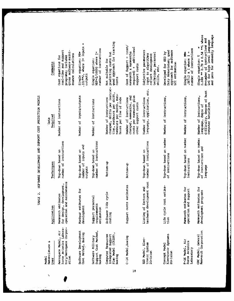
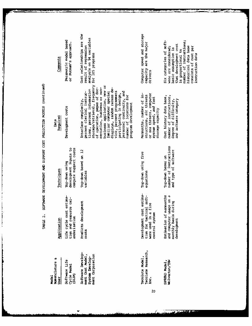
A large number of software cost prediction models ortechniques are described or referenced in the technicallitrature reviewed. Twenty-one models were examined in somedetail in an effort to identify commonalities and differencesin the cost estimatting approaches. Ten models are limited tosoftware development cost, while eleven have software supportcost as a primary or secondary output. Table 2 lists the modelsin alphabetical order.
Software development cost prediction models are generallymore sophisticated than the techniques used to estimate softwaresupport costs. Support costs are usually computed as a function
of either development costs or program size. Regardless of thedegree of sophistication, the models do not compute cost
estimates to the depth or detail necessary to evaluate the impactof alternative software designs or support concepts on softwaresupport costs. Most models concentrate only on manpower.
17sXWM mPa.AW BEAN4 =u IM
+ 2U) U it -
4) 1C U ) 0 j 1
.ad 4 A.2 -. a0 4. a)fl 4.).) 4 UI
44 MF-w wU) 0 -1 10U): . )w 0 4)44 41 EL 20 U0) 041 40 rdiy ;joj~ CC ICD .0
~ i U, 4. , .4)00 U 0 4, x 'o4J44 )i4.) 4.) 4JX 0. 6
0 .) 4J w -4N 11) :3uea 0 U.. c.-4 0i)iC- - wd '4 -4) Z 0.i- 4tU) " U) . V) ) 4 -1 4) >.4
Cfl M 0 UI) w.0:U 0 :1C U.)L.U UC *C w_%.
4.. LO ) 4 )wc
CdU4-4C fn
C41C U)C r- M w I 's U l.
C 0- w % U , 0 0-0d 4J 0 . ., 0 4 CO . ...
4-' It L- w)) d d .5 ) t ~ 4) -4 4.) 4)t
C 0 uw 44JW =W 4J04 1-' 4J 41
49 1&4 44 4'4-4 W-0 44 *44 44 144 .4Ja - '0. to 0* 01 0 0~ 0 0 0 DiI , 0z 0 0 L 2 3 li
z~ z
C 2 Cul 0 V 0 0
CS C C
u C C (a)
4J 4.) 0
~~~~ 0~0 .44~2~
U) 0 4J
Cd 0'2- 544 445 4
U)OC 4 U)
di-4.- 44 44E- 4)4 diL : s _0
4)0 4J0444 w )C 44)4)..-4U) 0i
4)1 Us04
CC u)4 E44U 0.U) 4
04)0 fa w U)2 00J419
m a) 0
004J 6 49 ~ 4- 444 4.. d4~~~0~t LO~d to4 W)~ di441
i di 41- 001m
0>0
C.) -4 .
18 M4,

'4-
E 0 j it( c 100)
r-- 00 4) a~ 4 4 M.0(O C)4.I 40-4 --. )-,0I' W w0c to -~ 0) . 0C) 00 .21 M- 4)')
c: u r_' 4-' 2 00- .l4. 11
4
-' luj 4W In' &4 "' - W> 3: W
(n '- N 0--4 1,4 -0-- WW0 c- M u4400
-Z 2 'W 4'- 0-) IC 404 8.
u4- 9 E-- W U)*0 01 u1
>.rm -r
o '~ V 2u% '0
~~ OW '. r- 4j U( ' 0 ~
c CI 4-(0 X 4J 1
.2( 0 (0 Wo44R 4 0.- 418 3" .0
41( 0-. c 0404Q.6 0C
o0 4 M M 4444J 44 4d 0 3.0
0 (000 41.2 W
4-' U) 04 0 0((W -' W cr U04 0) J (
.0
040 0' 044J( 40 0 44 C04 s 8 0 0
W-4 0- ;n
4w 04 - :300 0444 204 '4 WOMVX(0
W(0 04 >1 0
2. 2. & Uu c
DI i'n 'B , 09
41
4 .1 C
I ,,.. ..,G) A 0-64r
U) (a M0 0r 0-L 0) 4
4.10 *'0 - . ( 0 40E0- (0 4-4J00M
h.4J) ,W 4.,U4.1 V L. w C 4. m u'
,0on, 0.WO C .
Ai -4 -0 w C ( 0 , 4J . 0. 0
0 .4.1 . .. 0) w 4 r4..41 °5 0 U) L) o oo
4) 4) W, (.DL40 (A . ,0 o.410
*.4 4-J U4Q.J -W t 2 w
s a _4 >, *'R .a ua01 z -1 & .> C*D 4 41
0 oo w
8oEr u a,4.. (n C) Uc U0
r- U r
r_-W M0) 40 U U 4-1 0) 0 4J 4J 40 ELo 4.. -4 44 ~ 04) ( 0 0, w
At 04. U) En0U )W4 JE)4 44 U 4-4si..J44 C-' U ) . w~ U.LrOji
U) - M > RM U 4-. 41 04-J ( Ca (JV 0
414. u C3r_ W - '44 4
7oW ML. M
8 m r_ 1-4
Wa E) a; 28 0
02
.C
>0 0 w.4J U J)J.O
440
20

Currently, only two software cost models are available topublic users on a widespread basis: the RCA PRICE S2 model andthe SLIM model based on L.H. Putnam's approach. SLIM computestotal life cycle cost (development and support) while PRICE S2computes only development cost (and time). Both are parametricmodels and have had a large impact in the area of software costestimating. Putnam's approach is significant in that hepostulates that total required manpower, development time, andsystem difficulty are fundamental parameters of any softwareproject. Furthermore, Putnam's approach has the desirablefeature of indicating when estimating parameters fall outsideof practically achievable regions. PRICE S2 (and recently S3)is one of the RCA family of PRICE models. Numerous governmentorganizations are using or planning to use PRICE S2 to estimatesoftware development costs.
COST DRIVERS AS PERCEIVED BY MODELLERS
Many authors have noted that software development costsare consistently underestimated, while overestimates are rare.This historical tendency toward underestimation may indicate thatnot all key drivers of software cost have been identified orincluded in current software cost prediction techniques ormodels.
Examination of software cost models served to identify someof the factors contributing to software cost. Program size andcomplexity are probably the two most significant factorscontributing to software development cost, since these parametersare considered in all of the cost models. Other major factorsinclude the stability of software design requirements and whetherthe hardware design is pretty well frozen, availability of thedevelopment computer to the programmers, computing speedrequirements, degree of fill of the operational computer mainmemory, applicability of previously developed software,competence/productivity of the programmers, and the developmentschedule requirements. Table 3 lists the major factorsconsidered by the models reviewed. Those factors are groupedinto six categories:
* Requirements variables address the system and softwarerequirements.
*Design and Coding variables describe the size andfunctions of the programs developed to meet therequirements.
* Programming Environment variables describe the kindsand productivity of programmers and the hardware andsoftware support they have.
* Management Environment variables consider managementinfluences on the programming process.
21
~ ,.- -

TABLE 3. COST MODEL FACTORS
REQUIREMENTS PROGRAMMING ENVIRONMENT
Program type/application Programmer experienceTiming requirements LanguageOn-line program ApplicationRequirements change/design Programmer participation in
stability designResponse time Personnel continuitySecurity classification Maximum number of programmersVagueness/lack of knowledge Percent senior analysts
of requirements Percent senior programmersInnovation required Average programmer utilizationDesign carryover $/ManyearSystem interface complexity Travel required
Programming philosophyDESIGN AND CODING Closed/open shop availability
Development not at operationalNumber of object instructions site
delivered Program turnaround timeProgram complexity Use of automated validation/Language verification toolsSource instructions writtenNumber of functions MANAGEMENT ENVIRONMENTTypes of functions (mix)Number of subprograms (modules) Amount of externalNumber instructions/module documentationNumber object instructions Schedule realism
not delivered Coupling - system/SWPercent object instructions engineering
reused Orgn. resp. for SW managementPercent source instructions Number of agencies concur/review
in POD Customer inexperienceTypes of instructions (mix) Total nr. document typesNumber of words in data base Validation/verificationNumber classes in data base responsibilityNumber of input variablesNumber of output variables HARDWARE CONSTRAINTSFirst program on computer
Core capacityConcurrent development
INSTALLATION, OPERATION AND Number of bits/wordMAINTENANCE Machine speed
Computing costNumber of user centers Special display equipmentFrequency of operation Random access device
Input/output capacity
22

Hardware Constraints take into account the effect oftarget computer limitations on programming difficulty(e.g., memory size).
Installation, Operation and Maintenance variablesdescribe the impact of operations and support ondevelopment programming. (In the models reviewed, thisarea related to large ground-based installations.)
Within each category the top two to four factors (i.e.,those included by the most models) appear at the top of thelist. Table 4 lists the major factors accounted for by PRICE-S2,probably the most sophisticated software development cost modelin wide use today.
VALIDITY OF COST MODELS
Recent studies of development cost estimating methodologyhave concluded that "cost estimation methods must rely on theestimators' prior experience or rules of thumb derived fromhistorical dgta which are inappropriate or inaccurate." An AirForce study, for example, took eight cost estimating models andapplied them to six different computer programs. The resultsof that study are presented in Table 5. Dollar values arenormalized to 1.0. Analysis of the results in Table 5 revealsnot only a wide variation among cost model estimates on the sameprogram (as much as thirty to one), but the fact that the biasesare not consistent among the models. Even though model #8 isalways the high estimator, its degree of highness is variableModel #3, which tracked the mean for cases A-D, estimated verylow on cases E and F. Note also the actual costs on cases Eand F, and the estimated actual costs on cases C and D. Neitherof those sets of numbers tends to give any great degree ofconfidence in the outputs of the models. Of course, a majorcause of variation is probably the difference in data base sizeand attributes used to develop the cost estimating equationsof the various models.
I. J. A. Clapp, "A Review of Software Cost Estimation Methods,"Report Nr. ESD-TR-76-271, Electronic Systems Division, AFSCHanscom AFB, Bedford, Mass. 01731
2. T. G. James, "Software Cost Estimating Methodology," ReportNr. AFAL-TR-77-66, Air Force Avionics Laboratory,Wright-Patterson AFB, Ohio 45433
23

TABLE 4. COST FACTORS ACCOUNTED FOR BY PRICE-S2
Project size Project familiarity
Project type (e.g., MIS, radar, Intensity of efforttelemetry, etc.)
Changing requirementsOperational/customer environment
Programming languageHardware constraints (system
loading) Compiler power and efficiency
Existing design Development in-house or on-site
Existing code Project complexity
External interfaces (type Engineering requirementsand quantity)
Programming requirementsHierarchical design/functional
flow structure Configuration control
Number of functions performed Documentation
Amount of code per function Program management
Schedule constraints, lead times Design phase requirementsand overlaps
ImplementationECN effects
Test and integrationEconomic trends
Integration of independent projectsTechnology growth
Verification and validationFee, profit, and G&A
Multiple test beds/installationsComputer operation costs
Government furnished softwareOverhead
Purchased software (e.g.,Organizational efficiency subcontracts)
Skills Design-to-cost
Resource allocation with respect totime
24
...........................

TABLE 5. RESULTS OF COST MODEL STUDY
Program
Model A B C D E F
1 .35 1.05 1.12 1.09 ** **
2 .75 1.05 1.15 1.12 ** **
3 1.06 .96 1.00 .99 .15 .58
4 .70 .66 .50 .51 .60 .57
5 ** ** ** ** .34 .54
6 1.49 1.25 1.38 1.35 .17 .24
7 .27 .24 .25 .26 .35 .34
8 1.89 1.79 1.59 1.68 4.39 3.74
Average cost 1.0 1.0 1.0 1.0 1.0 1.0estimate, alleight models
Actual Cost - - 6.09* 5.95* .12 .34
* Contractor Estimate
** Insufficient Data
25

A recent Hughes in-house study inyestigated the feasibilityof forecasting software support costs. Part of the study effortinvolved comparing the manpower expenditure actuals fordevelopment of three Hughes embedded software systems withmanpower expenditure forecasts made using one of the equationsdeveloped by Lawrence Putnam. Putnam's forecast, if extendedinto the period of software operational use, would be a basisfor prediction of support costs. However, as Figure 3 portrays,the actuals don't match the Putnam forecasts very well. Indeed,actuals didn't match Putnam forecasts for any of three systemsstudied.
120- ACTUAL
THEORETICAL110 (BASED ON PUTMAN'S EQUATION)
-
20
10
SI I I I I )
1 2 3 4 5 6 7 8
YEARS
Figure 3. Actual Versus Predicted Manning Levels
1. R. W. Highlanid, "Exploratory Study of Software Support Costs,"IDC Ref 281742/111, Hughes Aircraft Company, 24 July 1979
2. L. H. Putnam, "A General Empirical Solution to the MacroSoftware Sizing and Estimating Problem," IEEE Transactionson Software Engineering , Vol. SE-4, July 1978
6026
...............................

A possible reason offered for the mismatch of actuals andPutnam forecasts is that development of embedded software formilitary avionic systems is significantly different fromdevelopment of non-embedded systems software of the type includedin Putnam's sample. In particular, the technology constant Ck,which Putnam estimates at between 5000 and 10000, has to beapproximately 1000 in order to satisfy his equation relatingprogram size, effort in manyears, and development time. Ckis a measure of productivity, and hence difficulty of developingsoftware.
CONCLUSIONS
The review of current approaches in software cost estimatingrevealed that none of the models examined adequately fulfillsthe AFWAL/AA requirement for estimating avionics embeddedsoftware support costs. Other specific conclusions are providedbelow.
Software life cycle cost estimating is hampered by a lackof good historical data on development costs, change rates andsupport costs, and good metrics for software quality, reliabilityand maintainability.
There are few (if any) well-validated, well-accepted modelsfor software development and/or support cost estimating.
Software development cost prediction models are moresophisticated than software operating and support cost models.
Software program size (or the number of instructions)forms the basis for most software development and softwaresupport cost models. Identification of other software programcharacteristics and development of additional estimatingrelationships are needed in the software support cost predictionmodel development effort.
Computing techniques and analysis approaches used insoftware development cost prediction models may be useful insoftware support cost prediction models.
Most modellers perceive manpower as the key driver insoftware costs; hence, almost all models include only manpowerpredictions. They universally neglect the cost of acquiringthe other resources required in the support process (e.g.,hardware, support software, documentation, etc).
27
: ,m mmm , ,, I I I | 1 - II

V. FIELD SURVEY FINDINGS
The purpose of the field surveys was to develop an overviewof the Air Force avionics embedded software population and anunderstanding of how that population is supported by AFLC.
General and specifi information on the AFLC support processwas obtained by reviewing pertinent Air Force and Air LogisticsCenter (ALC) regulations, procedures and operating instructions,and by interviewing key software managers and engineers at theALCs. Sample data were collected on six packages in order todetermine the general availability of the kinds of data neededto support a model development effort.
This section describes the basic findings of the fieldsurveys and provides a compilation of the essential informationnecessary to understand avionics software support in the AirForce. Major subsections are:
* Software population
* Software sample
* The software life cycle
* The AFLC resource-level planning process
* The AFLC software support process
* General observations
SOFTWARE POPULATION
OC-ALC estimates that there are now over 50,000 separateembedded computer system programs within the Air Force, plusa similar amount of program documentation. This is increasingat an estimated rate of 6400 packages per year. A centralinventory system for this software has been established at OC-ALCunder the auspices of the Technical Order Section of theOperations and Support Branch (OC-ALC/MMEDU). That systemincludes the Computer Program Identification Number (CPIN) systemand the Air Force Computer Resources Inventory (AFCRI).
Air Force Inventory Systems
The CPIN system is currently a semi-automated system (localword processing) planned to be on-line at Tinker AFB in 1981.Compendia of the data are presently issued monthly. Appendix Aof this volume provides a brief description of the CPIN system.
29
jp==M~ PAWE SLAaIL-ZO? 11UM

The AFCRI, which utilizes the same basic data as the CPINsystem, is on-line on the ASD Information Center computer atWPAFB. It is accessed via a remote terminal at OC-ALC. Thatdata base contains approximately 8,900 items as of January 1980.The majority of those are ATE programs, of which most are unitunder test (UUT) programs. Approximately 600-700 items arecurrently being added to the system each month. That rate isexpected to increase in the future.
Data for both the CPIN and AFCRI systems are supplied toOC-ALC/MMEDU by the various system/item managers or responsibleactivities utilizing AFLC forms 505 and 506 (see Appendix A).This is a major on-going, low-to-medium priority task. OC-ALCestimates it will take about 5-10 years to completely inventoryall embedded computer system software for which AFLC isresponsible.
PSCM Study Software Inventory
The PSCM study team compiled an inventory of softwaresystems in the categories of Operational Flight Programs (OFPs)and Electronic Warfare (EW) software by interviewing cognizantpersonnel at the various ALCs. The results of that inventoryare displayed in Tables 6 and 7. Table 8 is a list of ATE systemsoftware controlled by SA-ALC, the system managers for ATE.SA-ALC estimates that of the 400-500 identifiable ATE systems,about 20-30 are particularly active with regard to software.
SOFTWARE SAMPLE
In the early part of the study a sample of software packageswas selected on which to gather data. The sample consisted offive systems having OFPs (A-7D, F-15, F-16, F-111F and FB-IIIA)plus the F/FB-lII support software. Some data on change historyand manhours were also obtained for the F-11D at SM-ALC.
The F/FB-I1I support software includes simulation programsused for analysis, program development and verification/validation of F/FB-III OFPs. Support software is generallyconsidered as one of the resources supporting OFPs; in thisinstance it was treated separately to enhance the identificationand quantification of the key factors impacting avionics embeddedsoftware support costs.
Brief descriptions of the five systems and the F/FB-IIIsupport software package are provided in the followingparagraphs. Table 9 presents the pertinent data in tabularform to facilitate comparison.
I

TABLE 6., OFP SOFTWARE SYSTEMS
ALC SYSTEM
Warner-Robins F-15EAR
Pavetack/VATSC-130JTIDS
Oklahoma City A-7D/KAGM-69 (SRAM)ALCMGLCMB-52DB-52G/HE-3AE-4BEC- 135
Inertial Navigation Systems andStar Trackers
Ogden F-4F- 16GBU-15
San Antonio F-106 MA-iC-5F-5E
Sacramento F-111D* F-111F
FB-111A
TABLE 7. EW SOFTWARE SYSTEMS, WR-ALC
ALR-46 ALQ-125 APR-38
ALR-56 ALQ-131 ESAS
ALR-62 ALQ-135
ALR-69 ALQ-155
31

I.
TABLE 8. ATE SOFTWARE SYSTEMS, SA-ALC'Ii
Category Systems
Electronics ATE A-7 SE (Support Equipment)A-10 SEB-52 SEC-5A SEC-130 SEC-135 SEC-141 SEE-3A SEF-4 SEF-5 SEF-15 AIS MTTUF-15 SEF-16 SEF-101 SEF-105 SEF-106 SEF-111 SEHH-53 SET-38 SET-43 SEEngine SEGeneral Purpose SEMinuteman SESpecial Weapons SE
Funded Studies F-16Minuteman ATEE-3A
Process Control Pacer CometATS JEAStackerMI PVSF-100 Fuel ControlsVibration Diganostic SystemM37 Engine TE Automation
Test Software Development F-15 SE Add-onF-16 Support EquipmentMM4920 Modules4920 DQ Modules6625 Modules
E-3 SE ModulesF-100 EECC, EEC ATE and EHRModule
32

ID 4- U!. ~ . U,a. @ 41 .Uw ) 44 0- 4-i c _
0 (' W 4J 4
04 0 %D 04 OD c4 0 00
S 0 0p OP d
0 0 OD Go0 0 -W CA 044.w
00 C1 O r -'0 O
co >C~CO
0 4J 0' '
C.)~~4 4 J '
N. I. f..* w" "'('04 'r- 4"0 14"(1 1, , . D
I- -
m8lcn
4J ODN
.0 w1.
t-4 t& Y.-Y
;. >. 0
41 w1 w14 " 4 4.J> N ji 4.4 W14 m1 %1D
--- -4 -.4 >- >
- c ->14 .. a ..4J 8 0 ~ 4 41 4 4J 4J
> 14.
0049 4"
C6 a. 1
4J a. ~ 414 ~44W. &a -4 4n i
~U~l -4 -4- 0 .4
.0:I Owl.'4
33

A-7D OFP
The A-7D OFP was developed by IBM/Vought in 1968for use in the IBM TC-2 computer which controls navigation andweapons delivery functions in the A-7D. The TC-2 computer isa 16-bit machine with 16K of memory of which 15K or 89 percentis presently required for the OFP. The OFP is programmed inassembly language and is considered to be of average complexityrelative to other avionics software.
F-15 OFPs
The F-15 weapons system includes four programmable devices,of which the central computer and the radar data processorutilize OFPs. The other two programmable devices, theradar warning receiver and the internal countermeasures set,are part of the electronic warfare system and utilize EWsoftware.
The central computer OFP was developed by McDonnell Aircraftin 1970 for use with the IBM AP-I computer used for missionoriented calculations. The AP-I is a 32-bit word size machinewith a 16K memory, of which approximately 70 percent iscurrently required for the OFP. The OFP is written in assemblylanguage and consists of eight modules. The modular structureof the program allows considerable flexibility in accomplishingprogram changes or adding additional functions.
The radar data processor OFP was developed by Hughes in 1972for use with the HCM-231 computer. The HCM-231 accomplishesradar signal processing and control and provides the interfacewith other avionics equipment. The computer is a 24-bit wordsize machine with 24K of memory which is currently 100 percentfilled by the OFP. The existing 24K memory is scheduled forreplacement by a 96K memory device beginning in 1980. The OFPis written in assembly language and is considered to be verycomplex relative to other avionics software.
F-16 OFPs
The F-16 weapons system includes seven computer controlledsubsystems, five of which currently utilize software OFPs: firecontrol computer, stores management system, fire control radar,inertial navigation system and head-up display. Two subsystems(central air data computer and radar/electro-optical display)use programs loaded in Read Only Memories (ROMs). All sevenprograms are controlled as Computer Program Configuration Items(CPCIs).' Taken as a whole, the F-16 OFP software packageincludes 1,200,000+ lines of code programmed in higher order,assembly, and machine languages.
The fire control computer OFP was developed in 1975-1976by General Dynamics. The OFP is used with the MAGIC 362 F-2computer manufactured by Delco Electronics. The fire control
34
computer OFP functions include air-air/air-ground fire control,data display, stores selection, navigation, mission planningand fixtaking. The machine utilizes 16 and 32-bit instructions,16 and 32-bit fixed decimal point data with 24 and 48-bitfloating decimal point data. Memory includes 32K of 16-bitstorage plus 1K of 40-bit ROM. The OFP currently requires 26K(80 percent) of the available memory. The OFP is programmedusing both MAGIC F-2 assembly language (15 percent) and JOVIALJ3B-2 HOL (85 percent). Complexity of the program is consideredto be average relative to other avionics software.
The inertial navigation set OFP was developed by SingerKearfott Division with an initial release date in 1976. TheOFP provides navigation calculations for the navigation paneldisplay and provides back-up multiplex bus control for the firecontrol computer. The OFP is used with the Singer Kearcoft SKC-3000 computer which provides 32K of memory that is presently81 percent filled by the OFP. The SKC-3000 utilizes 15-bitinstructions and 19-bit data. The OFP is programmed in SKC-3000assembly language and is considered to be of low to mediumcomplexity.
The head-up display OFP was developed by Marconi ElliotAvionic Systems in 1976. This software was originally purchasedas a hardware configuration item and loaded in a ROM. The ROMwas replaced by an Erasable Programmable Read Only Memory (EPROM)however, and the head-up display software is now reprogrammableand thus classified as an OFP. Functions includecontrol/generation of displays for snap-shoot missile launch,and flight direction. The OFP is used with a Marconi/GeneralDynamics 16VE017003 computer providing 16K of 16-bit memory whichis 70 percent filled. The OFP is programmed in assembly languageand has not been rated in complexity due to the lack ofexperience resulting from its low change rate.
The fire control radar OFP was developed by WestinghouseElectric Corporation in 1976 for use with the Westinghouse radarprocessor unit. Functions include air-air and air-ground targettracking, ground mapping, inertial navigation coordinateupdating, and video processing. The OFP is presently loadedin a 32K EPROM Random Access Memory (RAM) using 16-bit wordsize. The OFP, however, presently fills 100 percent of theavailable memory, so expansion to a 40K EPROM is planned. TheOFP is programmed in assembly language and is considered to bevery complex relative to otner avionics software due to itslimited modularity.
The stores management system OFP was developed by GeneralDynamics in 1978 for use with a 8080 computer. The storesmanagement OFP monitors weapons status and controls/releasesweapons. The OFP currently consists of 34,816 words which occupy94 percent of the computer's 36K 8-bit word memory. The OFP isprogrammed in assembly language and is considered to be of highcomplexity.
35

FB-IlA and F-111F OFPs
The FB-IlA and F-111F OFPs were developed by Autoneticsin 1968 for use in the IBM CP-2 computers which handle navigationand weapons delivery in the FB-111A and F-111F aircraft. TheCP-2 is a 16-bit word size machine with 16K of memory. Memoryfill in each case is 99 percent. The 32K word OFPs areprogrammed in assembly language and are considered to be of highcomplexity relative to other avionics software.
F/FB-1iI Support Software
The F/FB-Ill support software package was developed byGeneral Dynamics in 1974 for use with the Harris/4 computer usedfor simulation of F/FB-IlI operational environments. TheHarris/4 computer is a 24-bit word machine with 480K of memory,of which 300K is required for the source lines and data filesincluded in the support software package. The support softwareconsists of 75 percent Fortran code and 25 percent machinelanguage code and is considered to be of high complexity.
THE SOFTWARE LIFE CYCLE
A basic understanding of the software life cycle willenhance understanding of software support. This is so becausesoftware support essentially consists of a series ofmini-development cycles. Each change undergoes virtually thesame process as the original software underwent when it wasdeveloped.
This section begins with a comparison of hardware andsoftware characteristics. The computer program life cycle asdefined in AFR 800-14 is then described. The Computer ResourcesIntegrated Support Plan (CRISP) is briefly outlined. Finally,causes of software changes are discussed.
Comparison of Hardware and Software
The software life cycle is similar to the hardware lifecycle, except that the manufacturing process is greatlysimplified, and "maintenance"* is really a modification process.Hardware goes through an engineering development and design
* Throughout this report "maintenance" will be used to refer
only to those changes that do not alter the functionalspecifications (input/output) of the software (i.e., errorcorrections or minor efficiency changes). "Support" is themore general term applied to the total change process.
36
...-~. xzj

phase; software has a similar development cycle, beginning withan analysis of software requirements. Hardware is fabricated;this can be either the final product, in the case of aone-of-a-kind system, or it can be a preproduction prototype.Software coding is similar to hardware fabrication. The softwarelisting is analogous to the hardware engineering drawing, exceptthat it is "as-built" instead of "build-to." That listing goesthrough numerous iterations as the code is debugged.
In the case of hardware, a major portion of the acquisitioneffort normally goes into the mnanufacturing cycle. In the caseof software, manufacturing (i.e., making more than one copy)is a completely automated process of taking the master andcopying it. Hardware, quality assurance/quality control isconcerned with ensuring that many units conform to the designspecifications. Software quality assurance/quality controlfocuses on the quality implications of software engineeringpractices, since a single master program is the main product.
Hardware reliability is a function of the fact thatcomponents physically degrade or fail. Software, however, neverfails or physically degrades (although the physical medium inwhich it resides may do so). Software unreliability is causedby inherent logic errors which were not detected and eliminatedduring development or verification. It is difficult to detectsuch errors because of the complex logical relationships andthe vast number of distinct internal states which exist in com-puter programs. No reasonable (i.e., affordable) amount of test-ing can completely check out any but the simplebt programs (al-though certainly a large number of critical paths can be tested -you can have as much confidence as you are willing to pay for).
Hardware maintenance (either repair or preventive) consistsof returning the hardware to its original state by eitherreplacing failed components or adjusting the mechanism (orboth). Software maintenance involves modifying the program,changing its original state by removing the logic errors(hopefully without introducing additional errors as a resultof the modification).
Hardware undergoes engineering modifications to fix designfaults (as does software) or to attain new capabilities. Asignificant part of software modifications is upgrading inresponse to new operational requirements. A major attractionof software is the relative ease with which new capabilitiescan be implemented, as compared to hardware retrofits. It istherefore important that software be designed with futuremodifications in mind.
In summary, software is similar to hardware with theexception that it never physically degrades because it is notphysical. The abstract nature of software, coupled with thelogical complexity of the structures embodied, causes it to havea different failure mechanism. This in turn causes a different
37

kind of maintenance process. Modifications of both hardwareand software follow a similar path. A number of software changesare often grouped into a single "block change" in order tosimplify confiquration management.
The Computer Program Life Cycle
The computer program life cycle, as defined in AFR 800-14,Volume II, "Acquisition and Support Procedures for ComputerResources in Systems," is diagrammed in Figure 4. The phasesdo not necessarily coincide with any particular hardware phase,but occur in relation to the requirement to develop particularComputer Program Configuration Items (CPCIs). The phases aredefined as follows:
Analysis Phase . The purpose of the analysis phase is todefine the functional performance requirements for a computerprogram. These requirements describe the functions the CPCIis required to accomplish as part of the system. Additionally,the functional interfaces and the necessary design constraintsare defined. This phase normally begins with the release ofthe system specifications, and terminates with the successfulaccomplishment of the Preliminary Design Review (PDR). Duringthis phase, various design approaches are considered, analysesand trade-off studies are performed and design approachesselected. The authenticated development specification formsthe baseline from which the design phase initiates.
Design Phase . The purpose of the design phase is todevel.oo a design approach including mathematical models,functional flow charts, an( detail flow charts. The designapproach should also define the relationship between the computerprogram components. The detail flow charts define informationprocessing in terms of the logical flow and operations to beperformed by the set of computer instructions. This information;s contained in the preliminary product -,peci ication and inormally presented and reviewed durinq the Critical nesign Review(CDR). The design approach is documented in a preliminaryComputer PrQgraa Product Specification and reviewed against therequirements of the development specification prior to initiatingthe coding phase.
Coding and Checkout Phase . The codinn and checkout phasenormally follows the CDR. The purpose of coding is to translatethe flow charts into computer programs and data. The purposeof checkout is to convert the initial computer program code anddata into an operational computer program. The determinationthat a computer program is operational is based upon checkingthat it produces correct outputs when operating upon predefinedinputs. This first check is usually limited with each computerprogram and, upon successful completion, leads into the test and
integration phase.
38
................
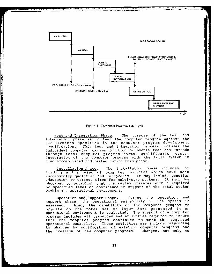
(AFR 800-14, VOL 11)
DESIGN
FUNCTIONAL CONFIGURATION AUDIT/PHYSICAL CONFIGURATION AUDIT
CHCOUT
PRELIMINARY DESIGN REVIEW
CRITICAL DESIGN REVIEW INSTALLATION
TIME
Figure 4. Computer Program Life Cycle
Test and Integration Phase. The purpose of the test andintegration phase is to test the computer program against therequirements specified in the computer program developmenteeification. This test and integration process includes the
individual computer program function or module test and extendsthrough total computer program formal qualification tests.Tntegration of the computer program with the total system isilso accomplished and tested during this phase.
installation Phase. The installation phase includes theloading and running of computer programs which have been
successfully qualified and integrated. It may include peculiar)daptation to various sites for multi-site systems. It includescheckout to establish that the system operates with a requiredc-r specified level of confidence in support of the total systemwithin the operational environment.
Operation and Support Phase. During the operation andsupport phase, the operational suitability of the system isassessed. Also, the capability of the computer program tooperate on the total set of input data presented in anoperational environment is evaluated. The support of a computerprogram includes all resources and activities required to insurethat the computer program continues to meet the requiredoperational capability. These activities may include respondingto changes by modification of existing computer programs andthe creation of new computer programs. Changes, not only to
39

the computer programs themselves, but also to the associateddocumentation, are addressed. Incorporation of new programsor program modifications to an existing system normally requiresreaccomplishment of all the phases in the computer program lifecycle. Hence, the computer program life cycle is a continuingprocess throughout the system life cycle.
Computer Resources Integrated Support Plan
The plan for logistics support of hardware during theoperation and support phase is documented in an IntegratedLogistic Support Plan (ILSP). There is a similar document forembedded computer systems and software called a ComputerResources Integrated Support Plan (CRISP).
The CRISP identifies organizational relationships andresponsibilities for the management and technical support ofcomputer resources. It functions during the full-scaledevelopment phase to identify computer resources necessary tosupport computer programs after transfer of program manangementresponsibility and system turnover. The CRISP continues tofunction after the transfer of program management responsibilityand system turnover as the basic agreement between thesupporting and using commands for management and support ofcomputer resources. The following items are included, asapplicable:
a. Offices of primary responsibility and management focalpoints for support of computer resources and thechannels of communication among organizations.
b. Planning for configuration management of computerprograms, including the assignment of configurationcontrol responsibilites during the deployment phase.This planning will reflect the operational and supportconcepts for the system.
c. Responsibilities for composite system integrity, whichinclude:
(1) Computer storage utilization.(2) Computer program operating time and prioritites.(3) Computer program interface techniques.(4) Computer program baseline integrity.(5) Utilization of computer modules and peripherals.
d. Documentation re-uired to support each type of computerprogram.
e. Responsibility for funding, scheduling. and systemintegration.
40
f. Personnel required for supporting computer equipmentand computer programs together with trainingrequirements.
g. Computer equipment and devices required to facilitatecomputer program changes, including acquisitionresponsibilities.
h. Computer programs required to support computer equipmentand other computer programs, including acquisitionresponsibilities.
i. Verification and validation (V & V) of computerprograms.
j. Plans to establish and operate necessary supportfacilities. Common and existing facilities will beused whenever practicable. The size and scope of thesupport facility will be based on workload predictions.
k. Provisions for the transfer of program managementresponsibility.
1. Provisions for system/equipment turnover.
Causes of Software Modifications
Changes to avionics software systems can be categorizedinto five different types:
* Corrections of coding errors and design deficiencies
* Optimizations of the computer code to save memory spaceor execution time
* Enhancements to existing capabilities
* Additions to existing capabilities
* Deletions of existing capabilities
The presence of errors in a highly complex real-time controlsystem (which is what most avionics systems are) is virtuallya foregone conclusion. It is almost impossible to completelyprevent their occurrence and almost as difficult to detect themall during development and test. However, under the appropriatecircumstances and operational environment, an error will manifestitself as a failure of the system to perform properly. Oneinstance was cited during the field surveys of an F-ll1 whoseindicated position would sometimes jump 8000 miles durinqflight. The problem was finally traced to two specificinstructions in a 1200-instruction block of code; if they wereexecuted while the computer was shifting from foreground tobackground mode certain counters would be cleared, which then
41
resulted in the erroneous position indication. Once the causeof the problem was isolated the solution was simple.
In addition to error-corrections, simple changes aresometimes made to enhance the efficiency of program execution.Both the above classes of changes are considered programmaintenance.
Another factor leading to software change is changes inthe hardware. Modifications of the hardware can be either inresponse to design deficiencies discovered during developmentand early production, or for improved performance later on.Very often such changes require corresponding changes in thesoftware.
The systems discussed in this report are built to respondto a military threat. A change in that threat environment canlead to a need to change the system; or new methods of dealingwith the threat may be developed. Such changes can possiblybe implemented by changing the software. The change might bean enhancement of an existing capability, or the addition ofan entire new capability such as a new missile. In either case,software changes will almost certainly be required.
THE AFLC RESOURCE-LEVEL PLANNING PROCESS
In the short run (i.e., less than a year or two) thequantity of resources (especially manpower and hardware)available to support software changes at any given ALC may beregarded as fixed. This then leads to the situation wheresoftware changes will be made up to the maximum level permittedby the available resources, rather than resources being madeavailable to support the required level of changes. (This canbe less of a problem when an ALC is supporting multiple systemswhich utilize similar support resources.) This being the case,it is desirable to have some insight into that originaldecision-making process.
The F-16 was chosen by AFLC as the first candidatefor processing under their Generic Logistics Decision Treeapproach. As such it serves as an example of that decisionprocess. The following kinds of questions were asked by the AirForce as part of that approach in making support resourcedecisions for the F-16 avionics embedded computer systems (ECS).
Are Governmental Functions Included? In order for AFLCto perform the inherent management functions associated withweapon system control a core of in-house engineering expertise,along with certain essential support resources, is required.As a minimum, a sufficient resource base must exist to permitthe system manager to make value judgements in evaluating change
42

requests, reviewing contractor proposals and accepting non-organiclly developed changes or modifications. Since non-avionic changes may have an impact on avionics software, thesecapabilities must be viewed at the system engineering orintegrated level. These resources are needed to providetechnical direction, perform technical analyses, evaluate systemeffectiveness, and manage the technology base.
Can the Functions be Segregated? In the case of the F-16,the resources required to perform the inherent management(governmental) function can be quantified and segregated fromthose required to provide direct operational support.
Is an Organic Nucleus Required? The organic nucleusrequired to fulfill the inherent governmental functions involvesan avionics equipment bay staffed by digital systems engineers,mathematicians and other professionals. Also a flight test areastaffed by instrumentation engineers having access to aninstrumented flight test aircraft will be required.
Are AFLC Readiness Functions Included? Certain readinessfunctions are inherent to combat weapon system software support.The ability to modify a program in response to a changing threatenvironment may spell the difference between mission failureand success. For the F-16, three digital avionics subsystemscontain logic which is critical to mission accomplishment.Digital avionics experience dictates that this logic will changein response to changing mission roles, changes in the operationalenvironment, enhancements to system capabilities andoperationally discovered deficiencies. Statistically, the peace-time change rate approximates 5% of the current program size.It is known that there will be a surge in this change rate duringengagement in a wartime scenario; this surge, however, cannotbe quantified before the fact. Of major concern for the F-16is the ECCM logic to be placed in the fire control radar, theweapons delivery algorithms in the fire control computer andthe ballistics equations in the stores management system.
Is Total Organic Accomplishment Required? Direct engineer-ing support for the fire control radar, fire control computerand stores management system can be provided as a separatecapability by procuring the necessary documentation for the threesubsystems, providing individual dynamic test stations, andaugmenting the established personnel baseline.
Is It Necessary to Increase the Organic Nucleus? Organicsupport of the fire control radar fire control computer andstores management system is estimated to necessitate more than16 new support personnel and additional equipment costing morethan $7M.
Are There Organic Obstacles? The fire control radar isunder a Reliability Improvement Warranty (RIW) which would bevoided by organic software support. Additionally, there are
43

studies underway to define how to improve its ECCM capabilities.Because of the RIW and the unstable baseline, establishment oforganic support is not recommended initially.
Is Interim Contractor Support Possible? The least riskalternative is to program for interim contractor support forthe fire control radar while continuing to define organicrequirements.
Are Contract Sources Available? Because the F-16 is inproduction, contract sources are available for the foursubsystems not yet set aside: the inertial navigation system,the central air data computer, the head-up-display and theradar/electro-optical display. There is no indication that thesesources will become unavailable in the foreseeable future.Contract sources could be developed to provide scientificcomputer support; however, this appears not to be cost-effective.
Is a Cost Study Required? For the inertial navigationsystem, the central air data computer, the head-up-display andthe radar electro-optical display. AFLC does not presentlypossess the skills necessary to accomplish in-house engineeringsupport. Additionally, a lack of source data for the centralair data computer, head-up-display and radar/electro-opticaldisplay renders in-house engineering support for these systemsimpractical. In light of the above considerations, a formalcost analysis is not deemed necessary. For these four avionicssubsystems, OFP support will be provided contractually.
THE AFLC SOFTWARE SUPPORT PROCESS
Within the Air Force, software is basically supported eitherin-house or by contractors. In some cases the level of in-housesupport is augmented by on-site contractors. This study focussedonly on support which occurs at the five Air Logistics Centers(ALCs) and is performed by either Government personnel (CivilService and Air Force) or on-site contractors, or both.
This section describes the support process both generallyand at the specific ALCs. The analysis of those factorsrelating to the cost of that support is discussed in Section VI.
At each ALC the basic responsibility for support of embeddedcomputer resources falls within the Engineering Division of #heMaterial Management Directorate. The Computer Resources Branchis designated MMEC. Specific details of organizationalimplementation at each ALC are treated later in this section.
General Description of the Support Process
Avionics embedded computer system software support isessentially an ECP (Engineering Change Proposal) process. Eachproposed software change is evaluated and processed as an
44- -- ---.. ..... ...4

individual entity. There are many similarities to softwaredevelopment cycle activities in the aspects of design, codingand verification/validation. However, a number of changes arenormally processed together and released for operational useas a block update to the software. This is done in order tominimize configuration management problems. The primary toolfor processing changes to OFPs is the Avionics IntegrationSupport Facility (AISF). The same basic processes are appliedto other categories of embedded software, such as EW and ATE.This subsection describes the AISF, the basic OFP change process,and the configuration management requirements.
Avionics Integration Support Facility: The AISF is abroad gauge engineering tool. It is used not only for softwaresupport, but also for hardware support, system support,engineering studies, training support and augmentation of systemmaintenance capabilities. Table 10 lists some of the functionsin each of those AISF activity areas.
An AISF can be considered a collection of hardware andsoftware assembled in a ground facility for the purpose ofperforming the activities required to implement changes inavionics computer programs, including integration testing ofsoftware and hardware changes. It consistsbasically of: 1) various functional simulations used for problemanalysis and solution development; 2) a broad range of supportsoftware tools such as compilers, assemblers, verification/validation tools, analysis programs and management systems;3) a dynamic exerciser to more completely check out thecharacteristics of a proposed solution; and 4) an integrated testbed which serves to verify the adequacy of a total set ofsoftware and hardware changes. Aircraft flight tests are thenused as the final "proof of the pudding."
A specific implementation of an AISF is shown in Figure5 as an example. It includes the basic elements needed tosupport OFP software. The F-1ll AISF consists of an avionicsintegration area, subsystem test area, OFP dynamic simulationarea and computer support area. Instrumented flight testaircraft are also used in the support process. The integration,simulation and computer support areas are used extensivelythroughout the change process while the flight test capabilityis extensively used during the test and evaluation phase.
The integration area, which contains avionics integrationtest equipment (ITE) , is used to integrate the OFPs with theavionics system. It further is used to recreate flight problems;check hardware/software interfaces; evaluate timing, stabiliza-tion and synchronization; and to conduct OFP/avionics systemcompatibility tests. On-line OFP change capability is availablein this area, which enables efficient and expedient implementa-tion of trial solutions.
45

TABLE 10. AISF SUPPORT OBJECTIVES
SOFTWARE SUPPORT
Problem/Modification AnalysisModification DevelopmentOFP V&V
- Development Test & Evaluation
- Independant Validation and Verification
HARDWARE SUPPORT
Analysis
Integration
SYSTEM SUPPORT
DesignAnalysisIntegration
* Documentation Validation & Modification
ENGINEERING STUDIES
Elffactiveness* Reliability
Ma inta inabilityTrade Offs
TRAINING SUPPORT
Operational ProceduresAvionics Subsystems Famail iarizatioin-Mai.r.tenance Procedures
* MAINTENANCE ALJGMENTATIO-11
F,--'ure Verificat.4on'rst Pi~ocedure 0ew-i opmnwrtQu'rational Test 2.ruqramn Deve.!-pm-nt
46

AINC INEMRTO AREA IN OPTE UPOTAf
k ealinalI proem' TATC TSTNG TATC TER AT O MPTNNSSE* OTP A Femligh Tes DataRdu
IEMOI Prbe Addendumo Chne AnFinali
Gi CageReust Pobe Aayss otwr Co uatibin Tes ftn Prrmmn
Hadir PurbesSsem Avionis nTegrtinSpotFciy
The yn~rdam simultiotwareapoie acpblty o
their resident ()F~~~sIdnt imuattewoldassenoynhs
nostSUSYTE pars ARE the DYNAMI SIMULATIh dt nio QAEIAcusto37 stems whch prov ide ForNALl eltetae f F
MR-uton Fah iuto 'tr i aeuftre~tINAHoRpoARAAtYIn ADWR LLR AREV min-cmpte Proble/hnge aOnaircraest coiock-up specia refc devices an a Esimuation softwGUare
TReliblt comp iltyr Mdsp or :Oprationlfosmall co ptr suIrTh ieabilety i ewquent ncu 1 r E as lua; A E SeENcRIO r
Emvi o-enunce ofeia Prjspotsfwr;seilzdporm
----------tm n~ide EW irergt O/32 mini -c taLssim
~~F~~~~ *1OF miP-omue stmadAssem ta Rerl-:a t a
speia intrmentatuion paea prdese specifailly fo
mormutozsin acdteurdnalF flight perforiance lghs aarait -eiinre
mcnduct, toeia tenterall dev perirenc and miimltin ssionar
oacka47
suitability; analyze change and problem areas; test specificmodes and functions; and to obtain engineering data to defineand verify system performance.
The AISF technical staff consists of engineers, programmersand technicians. They encompass a spectrum of expertise on theaircraft system, avionics, computers, operational software,support software, bomb navigation, scientific programming,instrumentation, data reduction, systems analysis, configurationmanagement, and equipment and software maintenance.
The mainstay in developing and integrating software changesis a GS-855 Electronics Engineer (Embedded Computer Systems),typically a grade 12. An electronics engineer is necessarybecause of the requirement to understand the hardware and thetotal avionics system as well as the software. A typicalposition description is given in Appendix B of this volume.
The OFP Change Process: The basic philosophy of avionicssoftware changes is that of the block change cycle, as opposedto continuous changes. This means that as change requirementsand problems are brought to the attention of the supportingfacility they are collected for inclusion into the next blockchange cycle. The primary advantage of this approach issimplified configuration control of the complex software andsystems involved. Specific changes of an urgent or emergencynature can be handled outside the normal block change schedule,but they are the rare exception.
Figure 6 details the flow of an OFP through the changeprocess, while Figure 7 portrays a typical sequence andschedule. The phases are as follows.
The Feasibility Study Phase is conducted by engineering inaccordance with user priority requests. It consists primarily ofdetermining the update task for each change; scoping the resourcerequirements; investigating change impacts on other parts of theweapon system and support equipment; looking at computer memoryand timing impacts; investigating integration problems; anddetermining if each change requirement is technically feasibleand will actually provide the user with what is expected.
The results of the feasibility study are then presentedat an OFP Block Change Definition meeting attended by the user,the system manager and software engineering. Based on theresults of the feasibility study, an OFP Block Change Definitionis established and agreed to. Constraints adhered to are: theblock change contains only change candidates which do not impacthardware; the changes can be worked within existing resources;and the cycle time is maintained. Changes which do not meetthese constraints are referred to the system manager forprocessing in accordance with hardware procedures. The mainoutput of the feasibility study is the OFP Block ChangeRequirements Document.
48

r J DEVELOPMENT
OFP BLOCKC PRELIMINARY INITIALDELOMN,HANGE DESIGN DEVELOPMENTDEVEOPMENT
ENGRG DEFINITION•AS," 'No HARDWARE ENGRG .ENGRG ENGRG
H E IMPACT) AIS DEVELOPMENT *AIST DEVE OPMENT "AISF I.EMrS lEIE ------ Zj : TE - 'E:US -SIM SYSTEM -SIM SYSTEM REQUIRMENTS SIM SYSTEM BASEL
INE SIM SYSTEM
S MCOMPUTER COMPUTER COMPUTER.SYS MGR SUPPOR .T . .-/ SUPPORT / SUPORT
PROBLEMSII r . . .
CPU..SOFTWARE ANOMALIES
1~ ~ C]P(YTMIPT)CORRECTIONS
CHANGES IMPACTINGC SSE NUS P~e
DW RE R .MISSION SIMULATOR P F ... .HARDWARE REVERREID •TC AA[ _
TO S"'STEM MANAGER TECH DATAMISSION AND WEAPON *SYSTEM MANAGERICONTROL PROGRAM ROTS SESUPPORT SYSTEMS *.USE APPROVAL
DEVELOPMENT ENGINEERING TAPES & ADDENDUMS
MISSION AND WEAPONCONTROL PROGRAMSr NIEGATTOEII CNRLPOAMFORMIAL TEST&I EVALUATIO L PUBLICATION/
IMPLEMENTATION PREPARATIONRELEASE1 E IiF 1ti OFFP&MASTER AISF FLIGHT TEST *ENORP MISSION
ENGRG ENGG J ENGRG & OTAR MERGE AISF PROD PRINTING PROGRAMS.;SC TAPES •ENGRG -ENGRG PROD .I, "--- "ETr
- -- " I TE L iNSTRUMENTATION 'COMPUTER PNGR B-SIm SYSTEM * SiM system FLE TEST A/C SUPPORT *TECH PUIS•' COMPUTER - COMPUTER | -MAINTENANCEI -TECH PUBS eY G
'11"IL' ~ ~ ~ TS C-SYSMGS"SUPPORT SUPPORT -USER .YS MGR
INSTRUMENTED DATA T
& PROBLEMS/ANOMALIES--
.DEVELOPMENT TEST i.FIIGHT TEST I , SC-- - TI . TCTOIROCEDURES ROMTS & PROCEDURES * ;,lOT uRSI0 I FTION * TAPES
.FORMAL TEST AND 'It)COIMENT * T0-PROJECT TEST EVALUATION * IOT SPDD MANUALS
RAVIONICS INTEGRATION SUPPORT FACR LOCK CANE_ :INTEGRATION TEST EQUIPMENT 0 OSRI)
.. COMPUTER PROGRAM CHANGE PROPOSAL
Figure 6. OFP Change Process
The Preliminary Design Phase consists of: translatingrequirements into engineering terms; researching flow charts andlogic layouts; defining mechanization, interface, scaling, andtiming requirements; developing change narratives; determiningthe scope of impact to documentation, technical orders, missionsimulator and other weapon system software; and preparing andsubmitting the Computer Program Change Proposal (CPCP).
The Initial Development Phase consists of: establishingthe levelopment baseline block change programs; firming upmechanization; programming and testing preliminary code; andestablishing documentation files.
The Development Phase begins with the approval of the CPCP
by both the user and system manager. The development phaseconsists of: finalizing and testing program code for each OFPchange; developing engineering tapes, addendums, anddocumentation; developing the project test plan; developing
49

PROBLEKOQMTS , \INVESTIGATION &
- m"Y+/'° m' - " ,- - " I o- U"",
*RQMTS REVIEWT
e DEFINITION
• CPCP SUBMITTAL
*CPCP APPROVAL
* PROJECT TEST PLAN
e INTEGRATE CHANGES1* FLIGHT TEST RQMTS.
*TEST PLANNING MEETING
*USER LAB DEMO _j
*INTEGRATION TEST & EVALUATION*FORMAL LAB TEST & EVALUATION
*ENGR FLIGHT TEST
* OT&E FLIGHT TEST*USER MEETING & CONFIGURATION FREEZE-
*TECH DATA V&V/FREEZE
* FLIGHT TEST COMPLETE* PRODUCTION PROG VERIFICATION
#FINAL TEST REPORT
*TECH DATA MASTERS* RELEASE AND FINAL REPORT
Figure 7. OFP Change Cycle
flight test, data reduction and instrumentation test require-ments; preparing test procedures; and providing preliminary datafor mission simulator updates.
The Integration and Implementation Phase begins with thelaboratory integration of all OFP Block Change requirements.A user/engineering meeting is convened to discuss engineeringand user flight test policy and to conduct a laboratorydemonstration of each OFP change. Final reassembly of allapproved OFP changes with the development baseline program isaccomplished and the master engineering OFP tape produced.Verification testing and evaluation by the developmentengineering group is completed. Engineering source data fortechnical orders and engineering documentation is developed,Formal test and evaluation procedures are finalized. The missionand weapon control programs are produced. Laboratory test andflight test aircraft configurations are established to includeaircraft computer data dumps and data reduction software. Thesesteps are in preparation for formal test and evaluation.
50

The Formal Test and Evaluation Phase starts with theturnover of the master engineering OFP tape to a separategroup for test and evaluation. Formal testing consists of athree phase laboratory test, instrumented engineering flighttest, and user Operational Test and Evaluation (OT&E). PhaseI of laboratory testing is a dynamic functional test of all OFPmodes. When completed, the master engineering OFP tape iscleared for engineering flight test. Initial engineering flighttest looks at overall mission suitability and clears the masterenginee-ing OFP tape for user OT&E. Once cleared, OT&E and finalengineering flight test are conducted concurrently. Phase IIand III of the formal laboratory test are also run concurrently.Phase II is a quantitative test of performance, a look atperformane envelopes and an inspection of code and baselinedocuments. Phase III is the retesting of modifications resultingfrom problems discovered during test. Part way through formaltesting a meeting between the user and software engineering isconvened to review test results and to establish an OFP BlockChange configuration freeze. Mandatory corrections to programdiscrepancies are defined, implemented and retested; trivialanomalies are accepted; and in the event a change cannot beaccomplished, its coding is zemoved. Also, during this phasetechnical order source data is verified and validated by theuser, encineering and the system manager. Source inputs forthe mission simulator updates are finalized and delivered. Atthe completion of the formal test phase, the master OFP addendumtape, incorporating all corrections found during test, is mergedwith the master engineering OFP tape to produce the OFP releasetape and the final OFP Block Change documentation.
During the Documentation Phase the OFP release tape isconverted into a production version and tested. All engineeringdocumentation is finalized; the technical order masters areprepared and made ready for reproduction. The evaluation oftest results is completed and the final test report is issued.
During the Publication and Preparation for Release Phase theproiction OFP tapes are duplicated; engineering documentationand technical orders are published; the final OFP Block ChangeReport is issued; and the new OFPs and associated technicalorders are concurrently released to the user under a TCTO.
The OFP 3lock Change process from start to finish is highlyIechnical and primarily involves engineering resources. However,system management, technical publi-ations and user participationare essential. The system manager has complete responsibilityfor the cont-ol, coordination and integration of OFP changesinto the overall integrated logistics management support system,and participates to that extent. When more than one systemmanager is involved, the subsystem manager mist work with allsystem managers -o insure that all are satisfied.
The user is intimately involved during feasibility andchange definition to establish roquirements and priorities, and
51

to assure that requirements are properly interpreted. Further,the user actively participates during the integration and testphases so that performance can be verified and acceptance grantedprior to configuration freeze and OFP release. The user'sprimary participation, during these phases is in the laboratoryverification. During the documentation, publication andpreparation for release phases, the system manager and technicalpublications personnel are extensively involved in thepreparation and publication of technical orders, the duplicationof OFP tapes and preparation of the TCTO for release. Engineer-ing is responsible for the technical management, planning anddirection of the complete OFP change program and is also responsi-ble for the development and implementatlon of al. OFT changes.Therefore, engineering is actively involved in all phases, bothfrom the program management and technical detail aspects.
Configuration Management: Configuration Management isa discipline applying technical and administrative directionand surveillance to (1) identify and document the functionaland physical characteristics of a configuration item (CI) , (2)control changes to those characteristics, and (3) record andreport change processing and implementation status. It is alsothe means by which design engineering, and cost trade-offdecisions are recorded, communicated and controlled.
OFPs are managed as Computer Program Configuration Items(CPCIs). Configuration management procedures, although embodyingcommon principles, are established by each individual ALC forthe items they support. The procedures below are typical and
not necessarily definitive for any specific ALC or OFP.
Each computer program planned to be designated as a CPCIis identified. The specifications and associated documentationdefine the CPCI baselines which the Air Force will maintainduring the operational phase. Changes to the computer programswill require a corresponding change to the specifications. TheComputer Program Configuration Sub-Board (CPCSB) is the centralpoint for processing computer program changes.
When suspected system OFP problems are discovered in thefield they are documented and submitted in accordance with T.O.00-35D-54, USAF Material Deficiency Reporting System. They arereviewed and a recommendation submitted to the System Manageras to the action required. All such problems requiring OFPchanges are separated into "emergency change," "urgent," or"collect for next scheduled update" categories. Problems whichhave a significant impact on avionics system capability or safetyare placed in the emergency or urgent change category, inaccordance with MIL-STD-480 priority definitions. Emergencyand urgent changes will proceed quickly through the problemanalysis, coding and check-out phase. The design goal is toimplement the necessary requirements as quickly as practicablewith a minimum change to the source OFP. Design interfaceproblems are resolved whenever possible by person-to-personcontact, followed by formal documentation,
52
At completion of check-out, the change to the updated OFPundergoes independent verification, the goal of which is todetermine that the change solves the problem and does notinterfere with other normal operating modes. Verification isperformed in the AISF and flight test/range facility. Technicaldata is compiled during the development and verification/validation phases and made available to the appropriate technicalpublications organization for T.O. update. At completion ofverification, the updated OFP and T.O.s are fielded, and trainersand ATE ar updated as soon as practical. Documentation, suchas criteria, requirements, program description, and interfacedocuments, is made compatible with the new program.
Support software such as compilers, assemblers, simulators,loaders, link editors, and V&V programs are updated to reflectchanges made to the operational software. During the operationalsoftware change cycle, required changes to support software andhardware are accomplished to accomodate the operationalsoftware change. Both support hardware and software baselinedocumentation are maintained to show details of all changesrequired for a particular operational software change. Then,upon approval of new/revised operational software, these dataare updated to indicate permanent change approval. Changes tosupport software/hardware to enhance their capabilit aresimilarly documented and controlled.
Since software is intangible (can't see or touch it), thedocumentation must be very thorough in describing its functionaland performance characteristics. Equally important is therequirement to have total visibility as to how thesecharacteristics were derived. Without documentation that doesthese things, the on-going change process would eventuallycollapse. Figure 8 illustrates what is considered a completeset of OFP configuration control documents, and where in theOFP change cycle these documents are completed and available.The list is confined to the end item OFP and is not intendedto include documentation on supporting resources, supportsoftware or oth-ier portions of the weapon system impacted by theOFP changes. A similar set of documents is obviously requiredfor these areas. An exception to this is in the formal test andevaluation process. As noted in Figure 8, documents definingthe test configuration of the laboratory, test aircraft, andmission and w-apon control program are required. If and whenother test resources are used in formal testing, theirconfiguration would also be documented and become a part of theOFP configuration control documents. The physical documentationincludes both automated and manually prepared documents as wellas computer-stored programs.
A historical list of all requirements and problems ismaintained in the Master Software Requirements Document (MSRD).All OFP source programs and programs generated after the finalOFP Block Change assembly are stored on magnetic tape and hardcopy listings are maintained on mircrofilm or microfiche. The
53

PROB/REOMTS O& &' O'*INVESTIGATION t44 V ? i
-OPERATIONAL SOFTWARE TREQMTS DOC (OSl) I*OFP SOURCE MAG TAPE
*OFP BLOCK CHANGE "
REQUIREMENTS DOCUMENT"COMPUTER PF~RGAM CHANG J
PROPOSAL (CPCP)
-PROJECT TEST PLAN
-FLIGHT TEST REQUIREMENTS
-FORMAL TEST PROCEDURES*MASTER ENGR PROG. TAPE*MASTER ENGR PROG. LISTING* MASTER OFP SOURCE
*AISF CONFIGURATION-FLIGHT TEST AIRCRAFT CONFIGURATION.MISSION &,WEAPON CONTROL PROG. CONFJ
-MASTER ENGR ADDENDUM-MASTER ENGR ADDENDUM DOCUMENTATIONJ
*MERGE PROGRAM TAPE
*PRODUCTION PROGRAM SOURCE j- PRODUCTION PROGRAM TAPE
-FINAL TEST REPORT-VERSION DESCRIPTION DOCUMENT-SYSTEM PROGRAM DESCRIPTION DOCUMENT-MASTER SOFTWARE REOMTS DOCUMENT*TECHNICAL ORDERS AND TCTO
CONFIGURATION FREEZE *OFP BLOCK CHANGE REPORT
Figure 8. OFP Configuration Control Documents
OFP Block Change Requirements Document defines the initial blockchange definition while the final release configuration isdocumented using a Documentation Program. These documents becomea part of the OFP Block Change Version Descriptioi, Document(VDD). The Computer Program Change Proposal becomes the systemmanager's official configuration control document and is updatedas required to reflect the final released OFP configuration.All formal test requirements, plans, procedures and reportsbecome a part of the VDD and are a record of actual jFPperformance. The OFP Block Change Report is a summary of totalblock change activity and results. The System ProgramDescription Document (SPDD) is the OFP specification and isupdated with each block change. It describes each of the OFPsubroutines in detail and includes: narrative descriptions.inputs/outputs, interfaces, logic, timing, equations and flowcharts. The VDD is the historical record of the OFP Block Changeand include, all other block change documents. In summary, the
54

OFP source data, SPDD and program listings define the newlyreleased OFP and the VDD defines the OFP Block Change to it.Technical orders generally aren't considered configurationcontrol documents, but are shown because of their importance tothe user and because of the detail they offer in describing theOFPs and their relationship to the aircraft system operation.
Data Collection Systems
Data collection on software support does not, in general,go to the breadth and depth desirable to support a good, solidmodel development effort. The most extensive automated systemnow in operation exists at SM-ALC, where manhours are collectedand reported at the level of specific OFP block changes orsoftware support functions.
The ALCs usually have some kind of project control systemwhich tracks the status of individual program changes. WR-ALCis building an automated Engineering Data Management System toprovide an automatic means of tracking manpower estimates versusactuals over the lifetime of the set of engineering projectswithin the Computer Resources Branch, as well as all otherpersonnel charges (leave, training, etc.). That system is
expected to be operational in 1981. Typical data provided bythe system includes the following costs by specific change task:
Contractor costsOrganic Costs
PersonnelTDYTest RangeEquipmentMaintenance
AircraftA1SF
The costs are available both weekly and cumulatively. Estimatedand actual manhours are also provided by task.
WR-ALC/MMRR, the Electronic Warfare Management Branch, hasan on-line project control system for EW systems which tracksestimated and actual hours by specific task. Once a projectis closed out it is deleted from the system. There is thus nosimple way of obtaining an annual report of all manhours expendedon all tasks.
00-ALC has an automated Project Accounting and Controlsystem currently operating. It tracks estimated and actualmanhours by task identifier, but a manual analysis would berequired to summarize manhours by task type. That system doesnot track all manhours, but only those expended in support ofspecific program changes. Figure 9 portrays a report producedby that system.
55

4 I, 3- 9-4 0 U 0 U U 04 a ci
a aV C C C C 94 * Ci C 14 U V V4.5 - N N C N C N 4 -~4e - - -a oat
a wV.it..
QUIt ~N N N N N N N N N % NC0 C 11)Q N N CL Cc CO CV -~ -aitE 4.53 itO IF' AN 44, Cci CC at EC MCOI4 U UN UN V V I 4 I J. ~~.WC 4 4 U' 4 0 U 0 U N NNUt V IA. 9- it it 4 4 4 4 ~P U C C 0 U U U N N*2e 4
Ce a .~ a a ~ '~ ~ a a**ee*********e** Re*.*t*4 e.e..e. tea....
9-CR 0 0 0 0 0 31 0 N a r InCUt - N N - - -II U *UNt N N N N N N N N N N Nft4* 0 0' U' N II U' C N 0aCe - C it II N U' C U' 0aVe
* . . . ee:.:eee a:. e~..:ea. ~ * * : *e~.t
* ~ . ~t: U' N C N N N C 5' 0N tat - - - - It -
e U ~ 0 0 U' 0 U' 0' 0 0' 0 iF 0N Ii' ~ U' CI N U' F- N CI N U' F Cl3-I. -
* Ii' * V41R iF 31 0 Fl' 0 0 0 N U' C U' -aN D itC N N -4, ~ite
* - C u~eta~- U' V a a a u 4.2V it1)C 4 4 V 4 it it C Lii JN 0 a C U 3 ~ 3 U N I N C ~ 4 0a - a e UIn it U V U 0 V 0 U 0 0 0 Uii ~ a a a ai a a U' it ci C U' U'* 4 1) ~ WIC
UIVICWi~iIila N Ii Ic
C >4*£ W ~ it a it it it it it It it it it
WI... 4 4 4 4 4 4 4 4 4 4 4* q c a a ~ C a a I C I 1 1 1C V 'P U' IF iF 1? 1 U' U' Ii' U'
* .4 N C C N N N N N N N N N N IiN CC * * * 0- 9 019-C I'd N - N N N N N N N N* 9 C '-.11)' N4 01CC UC * it it it it It it it it it it it* Ii * itUDE 4 4 it 4 4 4 4 4 4 4 4Fl 4 a a . a a a a a a a a 'I-bC 0 C U* Cl C *UCCCeteeC..ee. %ICC*CeCe..e....., *.~.
o I Ca ii. a a a a a c a 0 F) 0* N 4 I-C * . * *- U 4e C U' C 0 C U C 0 0I U C - N N U' 'ii C N C -
a zo.
Cl - Ne ICCC
5 U N C
e ~ cC- Vt V 0 0 0 0 0 0 0 V 0It it. * * * I)C C itC C C N N Fl - 4) - g a I*a
C£* 'I N Al - 0 C C 'ii-- C - - - -a e 5 * .- Ce
a.
U * 0 0 U 0 14 0 0 0 0 U 0it * . * I * C * * SN C 0 q 0 N N 0 0 0 0 0 0- t In CI 0 N N U' 'dl C C 4 61
OC - N I'd - - -4)0*IC WC
a0~
I iCC 0V 4ILC £ U'Si U'
C U 4 it - 9- £ U' CC C V - t V - US9-t iS 0 - - aC Ct C a it -INW. W I- P a .4 C SjC UC Ut) CV 1)10 I) Itt) '4 V Nt) 14 V CIV- ae UC UC 44 t Q 04 C V U * 1)0U C C4 -. Via C 4* VV V 414 Li CU' CU'* - 4 N U Fl Fl NW.3 ILN N CI'I CI 4N "I- 4 U 4 - S - VI 'CI Pa a C - a - P - a 0itt V it C C U IA. - U' U CIn UCS N V C U £ it £ it £V UC 4 N Ci P - P - it C -CD N C C. C C N C N V 00* a Iii 4 P it t it Pit aCt VI U IL S C C a IA. C SCit 9-C a - V 4 U' U 4 - U' Ca u . vi v~ * V N a u a , .~ a
56

Tracking manhours in support of ATE at SA-ALC is difficultbecause of the large number of organizations involved. TheSoftware Support Center (OC-ALC/MATT) can relate manhours toprojects, but cannot provide a good description of specificprojects without a lot of detailed digging.
Manhours expended in support of the A-7D software by theOC-ALC organization on-site at China Lake Naval Weapons Centerare tracked only at a general level or on annual basis. Becauseof the small size of the organization, a formal control system
is not required to keep track of what's going on.
OFP Support at OC-ALC/China Lake (ref Vol. II, Appendix 4)
OC-ALC (Tinker AFB, Oklahoma) is responsible for a varietyof systems, previously identified in Table 6 on page 31. Table11 lists the specific navigation systems and their currentsupport status. Most of the systems are currently beingsupported by contractor personnel. OC-ALC is in the processof developing a consolidated support concept to service a numberof the upcoming systems. Total forecasted manpower requirementsfor embedded computer system support within OC-ALC (D/MM) exceed100, growing to 185 by FY85.
TABLE 11. NAVIGATION SYSTEMS SUPPORT, OC-ALC
System Navigation Unit Support Posture
A-10 Form, Fit, Function (F ) ContractE-3A Dual Carousel IV/Omega Integrated with E-3A AISFAGM-69 Carrier (LN-15) Integrated with SRAM AISF
Air Vehicle (KT-76)A-7 KT-73 3 Integrated with A-7 AISFF-16 SKN-2400 IMU (F3 ) Integrated with F-16 AISFB52D GEANS Integrated with B-52 AISFB-52G/H Dual GEANS Integrated with B-52 AISFF-15 LN-31 ContractF-4 F4-E and RF -4C (LI-I2) Integrated with F-4 AISF
(to be replaced; F orLN-33 or?) and ARN 101(SKN-2400)
E-4 Carousel IV ContractC-135 Carousel IV (KC-135 and Contract or under
EC-135J) LN-20 development(RC-135) and DNC
C-5A Triple Carousel IV RIWC-141 Dual Carousel IV RIWC-130 LN-16, AC-130 Contract
Gunship (KT-73)F-5 Foreign Countries Contract
_ _ _ (LN-33)
57
The A"7D aircraft is supported through a joint venture withthe Navy at China Lake Naval Weapons Center, California (officesymbol OC-ALC/MMECZA). MMECZA has a work force of six civilservice personnel. Ad.itionally, they obtain eight manyearsper year of assistance from the Navy through a MilitaryInterdepartmental Purchase Request (MIPR). The civil servicestaffing consists of one supervisory electronic engineer, amathematician, a computer scientist, an equipment specialist(avionics), a computer operator, and a secretary.
MMECZA utilizes approximately 4500 ft2 of laboratory andoffice space. Computer support consists of eight DEC PDP ll/xxseries computers, a Honeywell Sigma V, and a Hewlett Packard9830. The resident support software to support the 16K A-7D OFPoccupies about 275K 16-bit words of core memory. Approximately50 flight tests of an instrumented A-7D aircraft are requiredeach year to check out software changes.
OFP Support at SM-ALC (ref Vol. II, Appendixes B, C, and D)
SM-ALC (McClellan AFB, California) is responsible forsupporting the F/FB-lII aircraft. In addition, SM-ALC/MMECFis responsible for a number of ground communications, electronicsand meteorological systems. The organizationl breakout ofSM-ALC/MMEC is as follows:
MMEC - Computer Resources BranchMMECP - F/FB-lII SupportMMECM - Software ManagementMMECS - AdministrationMMECF - Ground Communications, Electronics and
Meteorological Systems Support
1MMECP has approximately 81 personnel (as of December 1979)organized as shown in Table 12.
MMECP supports seven OFPs: one for each of the twocomputers (general navigation computer and weapons deliverycomputer) on each of the three aircraft types (F-IIID, F-11F,FB-IIIA) plus one OFP for the navigation computer unit commonto all three aircraft.
MMECP occupies 10,800 ft 2of standard computer-typefacilities. The AISF was described earlier, and is portrayedin Figure 5 on page 47. Equipment cost is estimated at $40million. The support software in the AISF consists of over700,000 source lines of computer programming. Flight testingrequires approximately forty sorties (120 flight hours) per year;this is on the basis of one block change every eighteen monthsfor each of the three aircraft, or one block change every sixmonths.
58j

TABLE 12. SM-ALC/MMECP STAFFING
Number of Personnel
Air Civil
Function Force Service Contractor
Management/Secretary 2 3FB-I11A S/W Engineering 1 5F-111D S/W Engineering 1 5F-ll1F/Pavetack S/W 1 5Engineering
Mission Programs 1F-Ill A/E Acquistion 1 1
SupportF-ill AISF Enhancements 15
and S/W SupportF-Ill OFP Mk II V & V 2 3Flight Test Support 5S/W Configuration 4
ManagementTSU 5Special Projects 3 8 10Major AISF Upgrades (5-10 off-
premise)
Totals 6 14 61( + 5-10)
OFP Support at 00-ALC (ref Vol. II, Appendix E)
00-ALC (Hill AFB, Utah) is currently implementing acapability to support F-4 and F-16 OFPs. The F-16 has sevencomputers, of which five currently have software OFPs. The F-4has three OFPs. The F-16 is still under contractor support;00-ALC operations are basically restricted to independent valida-tion and verification activities and preparation for F-16support.
00-ALC has an organization which is somewhat more segmentedthan the other ALCs. While 00-ALC/MMECA is responsible fordesign and development of OFP changes, MMETA provides independentvalidation and verification (both ground simulation and flighttesting) of those changes, and also provides AISF services toMMECA. ACDCS (comptroller) provides programming support forthe support software (both AISF and general purpose computercomplex). Table 13 provides an organizational breakout of the87 personnel involved in OFP support. 00-ALC is currently mannedto organically support only three of the seven F-16 OFPs. Theother four are under contractual support and require about 1/2person each. Radar support may go organic in the future.
59

MMECA and ACDCS occupy 5000 square ft of office space.MMETA occupies over 20,000 square ft of laboratory/office space.Computing support equipment for the F-16 is listed in Table 14.
TABLE 13. 00-ALC OFP SUPPORT
Organization Total F-16 F-4 Flight Test
MMECA(i) 33(2) 15 17MMETA 15(3) 7 3 4ACDCS: 39(4)
AISF 9 14GPCC 8 8
87(2) 39 42 4
1. Personnel shift between F-4 and F-16 in response toworkload requirements
2. Includes section chief.3. Includes section chief.4. Five persons shared between F-4/F-16.
TABLE 14. 00-ALC F-16 COMPUTING SUPPORT EQUIPMENT
IBM 360-65 - General Purpose ComputerDEC System 10 - F-16 AISFDynamic System SimulatorAvionics Equipment Bench (Tower)Avionics Intermediate Shop
The support software involves programs requiring over 1.8 millionwords of core, plus another set of data reduction, post flightand general purpose programs of over 65,000 lines of code andcomment. Flight test requirements are anticipated to be 90flight'hours per block change for the F-16.
OFP Support at WR-ALC (ref Vol. II, Appendix F)
WR-ALC (Robins AFB, Georgia) supports a number of systems,identified previously in Table 6 on page 31. Their major effortis devoted to preparing for support of the F-15 aircraft. TheF-15 has two OFPs, one in the central computer and one in theradar data processor.
WR-ALC/MMEC currently has 95 personnel assigned, including3 military, against an authorization of 130, excluding thosedevoted to ATE support. Of those 95, 50 are devoted to F-15support.
60

WR-ALC/MMEC is being reorganized from three into fivesections. One section will have three units. The neworganization will be as follows:
MMEC - Computer Resources BranchMMECA - ATE AcquisitionMMECT - ATE SupportMMECE - AISF Equipment and SupportMMECV - Validation & VerificationMMECD - Weapon System integration
MMECDF - F-15 OFP DesignMMECDA - Acquisition SupportMMECDM - Management
MMEC will ultimately occupy over 50,000 sq. ft. of officeand laboratory space. They currently have about 16,000 sq. ft.Computing support equipment will include a Dynamic SimulationSystem, a Data Reduction and Analysis System and a Flight TestPreprocessing System. There will be one fully instrumented F-15dedicated to flight test. It is expected to fly about 100hrs/year in support of all changes (hardware, software and EW).Approximately 15 flight hours are expected to be required tocheck out each software block change.
EW Support (ref Vol.II, Appendix G)
EW systems, including software, are managed at WR-ALC.WR-ALC/MMR (EW Management) is responsible for the EW systemsshown in Table 15. Current staffing (Dec'79) of MMRR, theEngineering and Reliability Branch, is 223 against 283 authorizedpositions. Their estimated manpower requirement for FY'80 is318. The breakout of that requirement by system is also givenin Table 15.
MMRR is organized into six sections:
MMRRC - JammersMMRRV - Receivers
MMRRI - Integrated systemsMMRRA - Threat simulation to test systemsMMRRS - Technical data, spares definition, user interface.
deficiency reportsMMRRW - Administration, budget, configuration control
MMRR will have an integrated support station (illustrated
in Figure 10) for each software controlled system they support.Any flight test requirements will be supported by the hostaircraft of the specific EW system. The F-15 Tactical ElectronicWarfare System (TEWS), for example, is tested on the sameaircraft which supports F-15 OFP software changes.
61

TABLE 1~5. EW SYSTEMS
System Personnel Requirement, FY80
ALQ-l31* 30.7
ALQ-165 (ASPJ) 4.1
ALQ-l55* 16.2
ESAS* 6.3
ALQ-117 5.3
ALQ-119 27.6
APR-38* 34.6
ALQ-125* 7.2
ALR-56* 18.8
ALQ-135* 11.5
ALE-45 4.0
IRS 7.3
USM-464 (FLTs) 16.4
ALQ-99 16.4
ARC 8.6
ALR-46* 39.6
ALR-62* 20.8
ALQ-153 5.7
ALR-69* 36.7
317.8
*Software-.controlled systems
62

- - EW SYSTEM 1
SUPPORT MASS
PERIPHERALS 'CONTROL
A COMPUTER REMOTEAVIONICS
TERMINAL
SIMULATION h
THREAT I I JAMMER &-
SIMULATION I RECEIVER JAMMER SIGNALANALYSIS m
EWOLS I ECSAS II,_.. I SYSTEM I
INTEGRATION& MONITOR
Figure 10. EW Integration Support Station
ATE Software Support (ref Vol.'II, Appendix H)
ATE has three categories of software: system software,support software, and unit under test (UUT) software. Systemsoftware controls the basic function of the ATE system. Supportsoftware is the assemblers, compilers, verification tools, etc.used in developing system and UUT software. UUT softwareconsists of those programs necessary to perform the testing ofa specific piece of hardware on an ATE system. Each unit whichis being tested on ATE has one or more UUT programs whichexercise the unit in order to test various functions.
SA-ALC (Kelly AFB, Texas) has been designated as the systemmanager for all ATE. As such, they control the system softwarefor those systems that are programmable. SA-ALC estimates thatof the 400-500 identifiable ATE systems, about 20-30 areparticularly active with regard to software. ATE system softwareis generally less formally controlled than OFP and EW software,due primarily to the large size of the programs. For example,the F-16 Avionics Intermediate ATE System has 500,000 lines ofcode. Table 8 on page 32 lists the present and projected systemsSA-ALC is supporting.
The major organizations at SA-ALC which are involved inATE software support are:
MMIM - Logistics Management BranchMMIR - Engineering and Reliability BranchMMEC -Computer Resources BranchMATT - Software Support Center
63

MMIM analyzes planning and programming documents and datato assure adequate logistics coverage. It also provides managersto administer, coordinate, and control the management of ATEsoftware.
MMIR has responsibility for full range engineering andtechnical integration of ATE equipment and software to assuredesign performance and compatibility, and to insure that allATE computer program deficiency reports are processed andcontrolled.
MMEC performs the following functions: identify minimumessential weapon system computer resources documentationrequirements for operational support; conduct or participatein verification and validation of assigned ECS programs; evaluateand define the cause of software deficiencies related to ATE,determine and recommend changes required to correct thosedeficiencies; maintain files and issue computer programs anddocumentation; evaluate contractor-prepared ECPs for computerprograms and documentation and apply cost effectiveness criteria.It is also the final engineering approval authority for embeddedcomputer systems integral to ATE systems.
MATT provides programming support resources as required.In particular, since SA-ALC is system manager for ATE, they arealso item managers for ATE components, some of which are them-selves tested on ATE, and require UUT software. MATT, as a majorresponsibility, develops UUT software for any ATE for which MMIhas management responsibility.
UUT software is that software written so that the ATE canperform specific tests on specific hardware items. It iscontrolled under the CPIN system as part of the specifichardware item, rather than as part of the ATE. As such, eachUUT program is controlled by the cognizant item manager. UUTmakes up the largest proportion of embedded computer systemsoftware in terms of number of programs.
GENERAL OBSERVATIONS
Software support within the ALCs is a task-orientedprocess. A set of individual computer program changes is groupedinto a single blocle change which is controlled as aconfiguration-managed item. (This is somewhat less true forEW and ATE software).
Although the same basic process occurs at each ALC, thereare differences due to particular organizational arrangements,workload requirements, and resource availabilities. Thesedifferences (especially in data collection systems) make itsomewhat difficult to discern the underlying parameters relatingsoftware change requirements to the resources necessary toimplement those changes. Those relationships are the subjectof the next section.
64

VI. ANALYSIS OF DATA AND COST DRIVERS
As part of the field survey process, various data wereacquired which relate to software support costs and utilizationof support resources. Those data include manhours related tosoftware changes, flying hour cost factors for test aircraft,quality ratings of software packages, and Line opinions ofexperienced software engineers as to the key factors which shouldbe considered in predicting support costs.
GENERAL SOFTWARE SUPPORT DATA
Data were collected from four different ALCs on sixdifferent sample systems. The ALCs and systems are shown inTable 16.
TABLE 16. ALCS AND SAMPLE SYSTEMS
ALC System
OC/NWC A-7DSM FB-111ASM F-111FSM F/FB-lll Support S/W00 F-16WR F-15
Table 17 summarizes the quantitative data related to generalALC support. Note that these numbers do not necessarily reflectthe total software support at the ALCs, but only that relatedto specific packages. Table 18 summarizes the data related tothe sample packages.
Examination of those tables reveals several interestingitems. The number of personnel per package varies from 8.5 onthe F/FB-lII to 25 on the F-15. It runs about 13 on the F-16.The reason for the variation on the two most recent systems needsto be explored in greater depth. It should also be noted thatof the 121K-words of F-16 software, about 72K are currentlybeing supported organically; the F-15 has approximately 40K-wordsof operational software.
The cost of support equipment at both SM-ALC and 00-ALCis on the order of $30-40 million. As that figure totally swampsthe annual operating costs for a number of years, in-depthinvestigation is needed to determine how sensitive that figureis to various OFP design alternatives and support concepts.A related fact is that vendor support on the Harris, Interdataand PDP computers at SM-ALC runs over $400k/year.
65
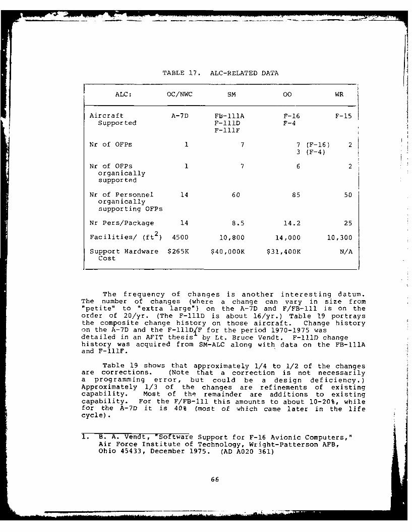
- -_.-" '
- - " -. . -.
TABLE 17. ALC-RELATED DATA
ALC: OC/NWC SM 00 WR
Aircraft A-7D FB-11A F-16 F-15Supported F-111D F-4
F-111F
Nr of OFPs 1 7 7 (F-16) 23 (F-4)
Nr of OFPs 1 7 6 2organicallysupported
Nr of Personnel 14 60 85 50organically
supporting OFPs
Nr Pers/Package 14 8.5 14.2 25
Facilities/ (ft ) 4500 10,800 14,000 10,300
Support Hardware $265K $40,OOOK $31,400K N/ACost
The frequency of changes is another interesting datum.The number of changes (where a change can vary in size from"petite" to "extra large") on the A-7D and F/FB-IIl is on theorder of 20/yr. (The F-111D is about 16/yr.) Table 19 portraysthe composite change history on those aircraft. Change historyon the A-7D and the F-IIID{F for the period 1970-1975 wasdetailed in an AFIT thesis by Lt. Bruce Vendt. F-111D changehistory was acquired from SM-ALC along with data on the FB-111Aand F-lIIF.
Table 19 shows that approximately 1/4 to 1/2 of the changesare corrections. (Note that a correction is not necessarilya programming error, but could be a design deficiency.)Approximately 1/3 of the changes are refinements of existingcapability. Most of the remainder are additions to existingcapability. For the F/FB-lll this amounts to about 10-20%, whilefor the A-7D it is 40% (most of which came later in the life
cycle).
1. B. A. Vendt, "Software Support for F-16 Avionic Computers,"Air Force Institute of Technology, Wright-Patterson AFB,Ohio 45433, December 1975. (AD A020 361)
66

n, - wm -A r- .-4 * 0-V
Ow PL4 i C ct.nE < C)
0, ') C N kl ON C) 0 1 1U) rU 'n CA C:
r. U)U 3 ra) a) 0
41>A (n > ~ 0n C - o C
(a - '0 H ::1 .2i -- n ( O a
..4 4.) .HN -WE,
'-4 w0o ',11-
1 4 0 4 1 .- (a 4 ) 4 J(a > a
A , :-4 + 'N -H = w wU F=44 44 :U CA 0 4- 0 co a) r I
SE 0 z U co UE DA r-ru 0 0, 0 m ~ ) HG a) 0>1 A L
< a
L) u)
C4 Q -0 4 4- 0 0
NP w~ 40C) 4-) 0 0q(a x E CD Ho X 03 NN -4C r
'N CA (N C\ CA A 0 - -4 'N M0 .
-4 -)
44 0 0
0o 0U]
-4 U] N0 4J Na
CA -4 CN 0) _q 0)0
-4 -0 0i ~ 1
'aj cc co CLC A 0 ~ N . 0> t4 M) - 4 o '0 -- =' 4 N(a Xn U] CA CA UX NA IT CD 0V4N. ~ '
Z ~ -4 -4 N -4 4 ' N N -4 2 4 C
W 44 )
CL U] >,. N1 44

TABLE 19. COMPOSITE CHANGE HISTORY
System: A-7 FB-111A F-l11F F-111D
Time Period: 1969- 2 1975 1970 19755 1970 1975-1978 1979 1973 1979 1973 1979
Total Nr. Changes 225 103 95 106 88 73
Corrections 40 38 49 38 46 40
Deletions 3 16 0 11 0 1
Optimizations 1 2 0 5 0 6
Refinements 80 32 31 29 32 19
Added Capabilities 91 15 4 23 6 7
Unknown 0 0 11 0 4 0
1. Source is Mark Jacobson, OC-ALC.2. Source is AFIT thesis, "Software Support for the F-16
Avionics Computer", Lt. Bruce A. Vendt, USAF, December 1975.
3. Source is A. E. Patterson, SM-ALC.
MANHOUR AND CHANGE DATA
SM-ALC has a detailed history of manhour and change .1atadating back to FY'77, covering all three aircraft. Table 20summarizes these data for fiscal years 1977, '78 and '79. Figure11 summarizes the F/FB-I1IA manhour data with respect to specificOFP block changes. The most complete data available are on blocksFB-15, F-12, D-19 and FB-16. The data for those blocks are givenin Table 21, and graphed in Figure 12. Note that there appearsto be a fairly regular relationship between number nf changesand amount of manhours. Flight test requirements do not correlatenearly as well.
Similar data for the A-7D arp shown in Figure 13, Table22 and Figure 14. The A-7D data embody various assumptionsregarding manhours per year and the application of those manhoursto specific block changes, and therefore are not as reliableas the F-Ill data. Nevertheless, they do indicate that themanhours per change are roughly the same magnitude as for theF-I1l, that is, roughly 1000 hours per change.
68
_ _ _ - - -6,

TABLE 20. ANALYSIS OF F/FB-lll MANHOURS
Aircraft/ OFP FY77 FY78 FY79 TotalFunction Block
FB-111A 18041 15069 9809 42919
FB-14 329 - - 329FB-15 17704 366 10 18080FB-16 8 14703 6932 21643FB-17 - - 2867 2867
F-111F 16926 8877 20243 46046
F-li 393 - - 393F-12 16533 7928 10168 34629F-13 - 949 10075 11024
F-11iD 13880 19376 14373 47629D-17 130 - - 130D-18 12072 963 170 13205D-19 1678 16732 3353 21763D-20 - 24 8366 8390
D-157* -1657 2484 4141
OFP Mgt/ 6391 3288 6467 16146Other
Software 23790 2997-5 2?D91 76660Support
Special 28982 35224 3254-.TU.
Leave/Training 19904 23580 24597
Total 27914 1135190 J 129131
*Special flight test/engineering required oiitr-'1i 3 norma1l~change cycle to analyze a specific weapon 0c ji'-'ry prof-I(-.
69
- a --
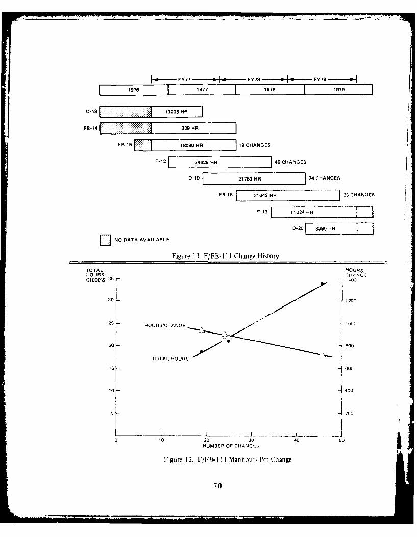
FY77 FY78 FY79
1976 T1 977 1978 T1979
D-18 13205 HR
F8-14 329 HR 111V-1-15 188 R~~ 19 CHANGES
F-12 34629 HR 46 CHANGES
D-19 21763 HR 24 CHANGES
FB-16 21643 HR' j5 Z-HANGES
F-13 11024 HR
DNO DATA AVAILABLE
Figure 11. F/FB-I II Change History
TOTAL HOURS"HOURS -H A N CCI00'S 35 f" 1403
30 - 1200
2~~ HtOURS/CHANGE -c
20 - 800
TOTAL HOURS
15 -600
10 - 400
5 -- 200
0 10 20 30 40 50NUMBER OF CHANG E';
Figure 12. F/Fli-I I I Manhoui' Per Change
70

TABLE 21. F/PB-ill BLOCK CHANGE DATA
Release Number Hr/ Flight TestBlock Date Changes Manhrs Change Sorties FH
tFB-15 12-77 19 18080 951 23 67
FB-16 6-79 25 21643 866 19 60.5
F-12 6-78 46 34629 753 13 34.2
D-I9* - 24 21763 907 37 88.2j
*Not formally released; awaiting further engineering action
TABLE 22. A-7D BLOCK CHANGE DATA
Release INumber HR/ Flight TestZt hancecc Manvr Change Sorties
12-72 0 13.5 8461
6-7i 20C 14.5 16311
4 n/a n/a
ik12-78 38 3(0 9102 103
t. Contractor: Asst*me 1880 manhr/yr2. Air Force: Assume 1760) mnanhr,"Yr
hie OFP 5iock dat,, for the F/FT -111 n6l - /P Ppea!i nd~c6,e t-hat the amnount of ef fort expende'i per ]nq e-J-atively constant across the blocks, in spitet- -hF -,r;~
i-ere can be significant variations in twn anw r'.i o-, (,t )i Iexpended on individual changes. Several conclusions can ( 9, wifrom ctis observation, specifically the following tw -manhours required for individual changes r~ c lgnormdistributed, and 2) technical factors due to resource ari-
limitations impact the mqix of changes accepted ir .
71
4- A- - -

'69 '70 '71 '72 '73 '74 '75 '76 '77 '78
F15 C H
17 CHI
60 OCHI
30 CH 13.5 MAN YR
j 20 CH ~ 14.5 MAN YR
58 CHANGES ]27 MANYR (AF)
CONTRACTORSUPPORT (MANYR) -10 7 5 6--
FY72 FY73 FY74 FY75
Figure 13. A-7D Change History
1600
HOURS/CHANGETOTAL MANVEARS 1400
30 - 1200
low,
20 -"
20 800
10 --10MA jYFARS
il200
20 30 40 50 r.NUMBER OF CHANGES
Figure 14. A -71) Matlhours Per Change
72
'4AM A~~t. ~#
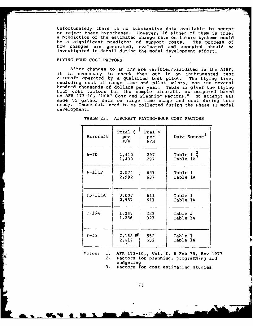
Unfortunately there is no substantive data available to acceptor reject these hypotheses. However, if either of them is true,a prediction of the estimated change rate on future systems couldbe a significant predictor of support costs. The process ofhow changes are generated, evaluated and accepted should beinvestigated in detail during the model development effort.
FLYING HOUR COST FACTORS
After changes to an OFP are verified/validated in the AISF,it is necessary to check them out in an instrumented testaircraft operated by a qualified test pilot. The flying time,excluding cost of range time and pilot salary, can run severalhundred thousands of dollars per year. Table 23 gives the flyinghour cost factors for the sample aircraft, as computed basedon APR 173-10, "USAF Cost and Planning Factors." No attempt wasmade to gather data on range time usage and cost during thisstudy. Those data need to be collected during the Phase II modeldevelopment.
TABLE 23. AIRCRAFT FLYING-HOUR COST FACTORS
Total $ Fuel $Aircraft per per Data Source
F/H F/H
A-7D 1,410 297 Table 1 2
1,439 297 Table 1A3
F-11±F 2,874 637 Table 12,992 637 Table 1A
FB-IIIA 3,007 611 Table 12,957 611 Table 1A
F-16A 1,248 323 Table I1,236 323 Table IA
F-15 2,158 $ 552 Table 12,017 552 Table 1A
Notes: 1. AFR 173-10,, Vol. I, 6 Feb 75, Rev 19772. Factors for planning, programming aiid
budgeting3. Factors for cost estimating studies
73
ie ,~ -~--

SOFTWARE PACKAGE QUALITY
It seems intuitively that the "quality" of an OFP will havesome impact on its modifiability and hence on OFP support costs.An attempt was made to measure the quality of several of thesample packages using a list of 45 quality attributes. Softwareengineers at the ALCs familiar with the packages were asked torate their package on the 45 attributes on a scale from 1 (poor)to 10 (excellent). A simple average quality rating was thencomputed for each package, summing the attribute scores anddividing by the number of attributes. (Not all packages wererated on all attributes.) The individual package quality ratingsare contained in Volume II of this report. It should be notedthat no attempt was made to control inter-individual differencesin package rating.
Table 24 shows the package averages. Note that the fouraircraft OFPs all rated approximately the same, while theF/FS-III support software is a full two points higher. The majorfactors on which it seemed to rate higher were accessibility,augmentability, legibility, maintainability, modifiability,robustness and simplicity.
TABLE 24. PACKAGE QUALITY RATINGS
A-7D 5.7FB-IIIA 5.2F-111F 5.2F/FB-IlI Support S/W 7.8F-16 (Combined) 5.6
Although the results of this initial study of packagequality showed no significant differences which might impactOFP support costs, this area should be studied in more depthin Phase IT. t
WHAT DO THE EXPERTS SAY?
As part of the field survey process, key people at eachALC were asked what they thought the key elements were toconsider in making a projection of software support costs ona new avionics system. Their responses are tabulated in Table25.
The greatest number of factors have to do with the overallsystem requirements and functions. The amount of spare memory(expandability) and the quality of programming support toolsavailable (hardware, software, documentation) were mentionedas very important variables. Programming language appears only
74
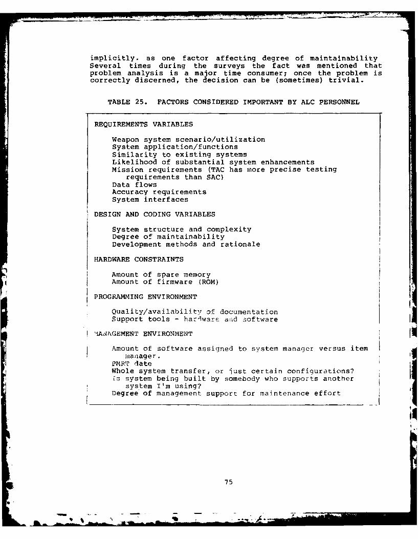
implicitly, as one factor affecting degree of maintainabilitySeveral times during the surveys the fact was mentioned thatproblem analysis is a major time consumer; once the problem iscorrectly discerned, the decision can be (sometimes) trivial.
TABLE 25. FACTORS CONSIDERED IMPORTANT BY ALC PERSONNEL
REQUIREMENTS VARIABLES
Weapon system scenario/utilizationSystem application/functionsSimilarity to existing systemsLikelihood of substantial system enhancementsMission requirements (TAC has more precise testing
requirements than SAC)Data flowsAccuracy requirementsSystem interfaces
DESIGN AND CODING VARIABLES
System structure and complexityDegree of maintainabilityDevelopment methods and rationale
HARDWARE CONSTRAINTS
Amount of spare memoryAmount of firmware (ROM)
PROGRAMMING ENVIRONMENT
Quality/availability of documentationSupport tools - harlwarc atid 3oftware
lAaAGEMENT ENVIRONMENT
Amount of software assigned to system manager versus itemmanager.
?PMW dateWhole system transfer, or just certain configurations?£s system being built by somebody who supports another
system I'm using?Degree of management support for maintenance effort
75
i75
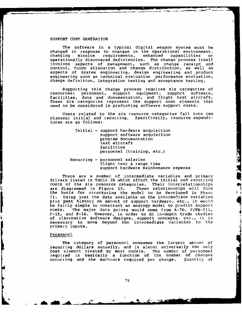
SUPPORT COST GENERATION
The software in a typical digital weapon system must bechanged in response to changes in the operational environment.changing mission requirements, enhanced capabilities oroperationally discovered deficiencies. The change process itselfinvolves aspects of management, such as change receipt andcontrol, funds allocation and change distribution, as well asaspects of system engineering, design engineering and productengineering such as technical evaluation performance evaluation,change definition, integration testing and acceptance testing.
Supporting this change process requires six categories ofresources: personnel, support equipment, support software,facilities, data and documentation, and flight test aircraft.These six categories represent the support cost elements thatneed to be considered in predicting software support costs.
Costs related to the six resource categories fall into twoclasses: initial and recurring. Specifically, resource expendi-tures are as follows:
Initial - support hardware acquisitionsupport software acquisitionprogram documentationtest aircraftfacilitiespersonnel (training, etc.)
Recurring - personnel salariesflight test & range timesupport hardware maintenance expense
There are a number of intermediate variables and primarydrivers listed in Table 26 which affect the initial and recurringcosts of the six resource categories. Their interrelationshipsare diagrammed in Figure 15. These relationships will formthe basis for structuring the model to be developed in PhaseII. Using just the data available on the intermediate variablesplus past history on amount of support hardware, etc., it wouldbe fairly simple to construct an analogy model to predict supportcosts. The major data points would come from A-7D, F/FB-lII,F-15, and F-16. However, in order to do in-depth trade studiesof alternative software designs, support concepts. etc., it isnecessary to move beyond the intermediate variables to theprimary inputs.
Personnel
The category of personnel consumes the largest amount ofrecurring dollars annually, and is almost universally the onlycost element treated by most models. The number of personnelrequired is basically a function of the number of changesoccurring and the manhours required per change. Quantity of
76
AhL AIM A
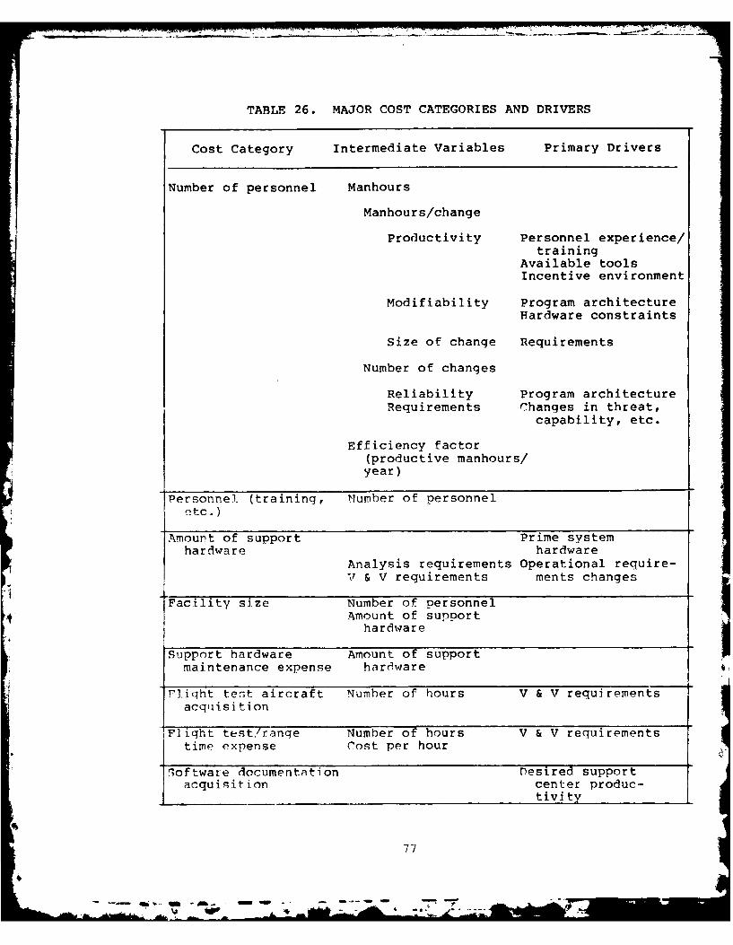
TABLE 26. MAJOR COST CATEGORIES AND DRIVERS
Cost Category Intermediate Variables Primary Drivers
Number of personnel Manhours
Manhours/change
Productivity Personnel experience/training
Available toolsIncentive environment
Modifiability Program architecture
Hardware constraints
Size of change Requirements
Number of changes
Reliability Program architectureRequirements Changes in threat,
capability, etc.
Efficiency factor(productive manhours/year)
Personnel (training, Number of personneletc.)
Amount of support Prime systemhardware hardware
Analysis requirements Operational require-V & V requirements ments changes
Facility size Number of personnelAmount of support
hardwareSupport hardware Amount of support
maintenance expense hardware
Fliqht test aircraft Number of hours V & V requirementsacquisition
F]ight test,/ranqe Number of hours V & V requirementstime expense Cost per hour
loftware documentation Desired supportacquisition center produc-
tivity
77
& - • -- .. . . . " -A -
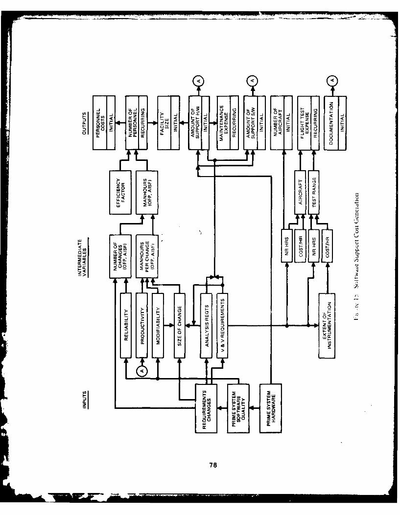
rd LU -JZ F . - 1 Zwj 0 - U 1-
0 oz w Z~ Z w -CL c4 -c x z
CL ILLU LU LU L D: U.
0
z' Q:0 z
L LL < LLL < ujw i
LuC.
tcz
uj cn o
UL U,2 co xx z
c I I < _ _ _ _ _ _ _ _ _ _ _ _ _ _ _ _
LU < (r78

personnel can also be affected by administrative requiremeats,training requirements, etc. Note that number of personnel isdriven both by operational software modifications and by supportsoftware (AISF) modifications.
The intermediate variables affecting the number of personnelare the efficiency factor (productive manhours per year perperson) and total manhours required (for both OFP and AISFsupport). Those manhours, in turn, are the product of the numberof changes and the manhours per change. Data are fairly readilyavailable on all those parameters.
However, rather than just extrapolating past levels ofsoftware change rates, it is desirable to understand the relativeproportion of reliability-induced and requirements-inducedchanges, what really drives the requirements-induced changes,and how well they can be predicted.
Similarly, manhours per change is conditioned by supportcenter productivity, software modifiability, and magnitude ofspecific changes. Productivity is a function of a number offactors such as available tools (software, hardware anddocumentation), personnel experience and training, and theincentive environment. Modifiability relates to the wholecomplex of factors regarding program structure (architecture,size, complexity, language, understandability, etc.) and itshost hardware (especially spare memory, and timingrequirements). The factors affecting size of a change also needto be understood.
Support Hardware/Software and Facilities
A major cost element which is universally left out ofsoftware cost models is the cost of acquiring the supporthardware and software required to make and check out changesto the operational software. This cost can exceed the cost ofsupporting the required personnel over ten years or more. Alsoin this category is the cost of the facilities required to housethe personnel and equipment. Once the hardware, software andfacilities are acquired, some expense is realized in operationand maintenance. These costs also need to be accounted for.Reasonable data on these costs can probably be fairly readilyobtained from the ALCs.
The analysis and verification/validation requirements,which affect individual changes, also need to be understood inthe aggregate in order to predict the requirements for supporthardware and software, and for flight test. Those requirementsestablish, in a sense, a minimum level of necessary resources.It may be (and probably is) desirable to increase those levelsin order to raise the productivity of the support center. Theinteresting question is, what is the optimum level of thoseresources?
79

nocumentation
Program documentation is another key resource which canaffect the cost of supporting operational software. Documenta-tion includes program listings, system specifications,flowcharts, coding and algorithm rationale, and any otherpaperwork which makes the task of implementing changes simpler.This documentation needs to be acquire.d from the softwaredevelopers, and then changed to reflect the current configurationof the operational software as that is changed. A related costis whether Technical Order pages need to be changed as a resultof changing software. Data on documentation costs (especiallythe cost of acquiring program documentation) may be difticultto obtain.
Aircraft Flight Test
The final cost element to be considered is flight test.Typically a dedicated, specially-instrumented operationalaircraft is used to check out both software and hardwarechanges. The cost of acquiring and instrumenting this aircraftmay or may not be considered in performing software support costanalysis. However, the cost of flying time to check out softwarechanges should certainly be included. Related to this is thecost of range time - those expenses related to utilizing aninstrumented test range.
The key intermediate variables affecting flight test expense(and initial aircraft acquisition) are hours of aircraft time,hours of test range time, and cost per hour for each. Data onthese parameters are fairly easily obtained.
As in the case of support hardware, the V & V requirementsare the primary driver conditioning how much flight test isrequired.
CONCLUSIONS
Analysis of the kinds of historical data available revealedthe following:
* There is generally reasonably good manhour data available,although some of it may require manual search of projectfiles.
* Reasonable estimates of personnel training requirementsare available.
* Acquisition costs of support hardware are generallyavailable. Acqqisition costs of support software may bedifficult to ascertain; in many cases much of that softwar4is developed by on-site personnel as part of setting upthe AISF and developing a cadre of trained personnel.
80

ADAO 476 HUGHES AIRCRAFT CO CANOBA PARK CALIF F/S 14/1PREDICTIVE SOFTWARE COST MODEL STUDY. VOLUME I. FINAL TECIBICAL-ETC(U)
6JUN 0 R B WAINA. 6 L FOREMAN, A P BANGS F3361579-C-1734UNCLASSIFIED AFAL-TR-BO-1056-VOL-I NL
I --7mEEl-h-ihmmhEImm4
-p
* The maintenance costs of the support hardware are readilyavailable when that maintenance is done on contract. Ifit is done by organic personnel it is probably buried inthe personnel cost.
* The cost of acquiring documentation on the operationalsoftware is often buried in the cost of acquiring thesoftware. Documentation cost may therefore be difficultto ascertain, especially since it is also often difficultto segregate the software cost from the cost of acquiringthe operational hardware.
* Standard factors on cost of flying aircraft are readilyavailable. The cost per flight hour should be similarfor instrumented test aircraft.
* Cost of facilities was not pursued. Standard cost factorsare probably readily available.
Preliminary analysis of the data revealed that there appearsto be some kind of regular relationship between number of changesimplemented and manhours expended. For the A-7D and F/FB-lllaircraft this was on the order of 1000 hours per change, witha range of 700-1600 hours. If the number of changes can beforecast with any degree of confidence, and if the change mix(i.e., proportion of small, medium and large changes) does notalter drastically, there is a good probability of being ableto predict manhour requirements.
Aircraft flying time in support testing software changesdid not reveal a regular pattern.
Software package "quality" did not vary significantly byaircraft, when computed using the crude index of averagedattribute quality ratings.
Experienced software engineers at the ALCs identified anumber of factors they consider important in projecting supportcosts. These factors need to be considered in the Phase II modeldevelopment, along with in-depth study of the factors affectingmanhour expenditures, factors affecting aircraft flight testrequirements, and the impact of software package quality.
81
VII. FEASIBILITY OF ESTIMATING SOFTWARE SUPPORT COSTS
INTRODUCT ION
Three elements are necessary in order to be able tosuccessfully estimate avionics embedded software support costs:
1) An understanding of the process by which those costsare generated,
2) The availability of historical data to establish thenumerical parameters and relationships describing thecost generation process,
3) The establishment of an estimating approach whichrelates the following: a) the purpose and desired useof the model, b) the input data available at the timethe model is to be used, and c) estimating algorithmswhich reflect the cost generation process and theavailable data.
The avionics embedded software support cost generationprocess is now reasonably well understood qualitatively. Thisunlerstanding is documented in Section VI.
The availability of various historical data has beenstudied. Quantitative data regarding manhours, salaries,software changes, support hardware costs, etc are reasonablyaccessible either through ongoing data recording systems at thevarious ALCs or by manual search of software project files andinquiry of cognizant cost controlling organizations. Determiningan appropriate estimating approach is the subject of thissection.
PURPOSE/USE OF DESIRED MODEL
The ultimate objective of the PSCM program is to developa software support cost estimating model for use in theconceptual phase to accomplish the following (ranked in orderof priority):
1) Evaluate software design alternatives (e.g., higher-order versus machine language)
2) Evaluate software support concept alternatives (e.g.,in-house versus contractor)
3) Make total software support cost projections for DSARCand preliminary budget planning purposes.
83 -
IFfiSC=Z PtAM BLAaK-?lQ IIJ6

There is no requirement for interfacing this model withany other models.
COST ESTIMATING APPROACHES
Twenty-one software prediction models were described orreferenced in the technical literature reviewed. Table 2 onpage 18 presents an overview of the cost estimating approachutilized in each of those models. Ten of the models are limitedto software development cost; the other eleven models considersoftware operating and support costs as the primary output oras part of the software life cycle cost.
Cost estimating approaches can be classified into three
basic categories:
* Analogy (sideways)
* Element estimate (bottom up)
* Cost estimating relationship (top down)
These three estimating approaches represent the candidateapproaches for use in the PSCM to be developed.
Analogy
The method of analogy is the most primitive estimatingtechnique. It involves comparing the project under considerationwith other similar projects. Scope and complexity factors areused to adjust the baseline costs to develop the estimates.Estimates can be made either by an individual or a group. Agroup goes through the same process as an individual estimator.They compare the upcoming project to similar past projects interms of size, complexity, schedule, etc., and develop individualestimates. These individual estimates are then combined intoa composite. The simplest and most straightforward way is tocompute the mean of the individual estimates. A somewhat moresophisticated approach is to require each individual to developpessimistic, most likely, and optimistic estimates for theproject. These are then combined in the standard PERT equationof
E o + 2m where E = final estimate4
o = optimistic estimate
m = most likely estimate
p = pessimistic estimate
84
Element Estimate
The element estimate approach is the next level up ofsophistication in estimating. The project is analyzed into itscomponent tasks, and each of those tasks is individuallyestimated. The estimates are then added together to obtain thetop-level estimate of resources. Schedule can be estimated bydevelopment of a PERT network which defines the critical path.Considerable technical/management analysis and judgement isrequired in the selection of input parameters for models usingthe bottom-up cost estimating method.
Cost Estimating Relationship (CER)
The CER approach is the most sophisticated estimatingtechnique. It relies on statistical analyses of historical costand resource data to develop estimating relationships based onkey independent variables such as program size and type, memoryfill, schedule constraints, etc. These independent variablesare then estimated for the upcoming project, input to theestimating equations, and the resource requirements computed.Most current software cost models are of this type. Few havebeen well validated.
Hybrid
Many models are a composite of two or all three of themethods described above. For example, the basic structure ofa model might be element estimate down to a certain level ofdetail. The inputs at that level could then be developed eitherby estimating relationship or analogy. This approach is usedin Optimum Repair Level Analysis, where transportation costsare one of the elements. Those costs are computed by inputtingthe weight of the item and the distance to be shipped (fromintermediate to depot maintenance). Those factors are thenmultiplied by a shipping cost per pound-mile, which was derivedby analysis of historical data.
RANKING COST ESTIMATING APPROACHES
Ranking of the three cost estimating approaches (sideways,bottom-up, top-down) by means of an objective methodology isbasic to the development of a recommendation for the costestimating approach to utilize in the PSCM. The rankingmethodology employed has to bring into account variousrequirements and attributes associated with each approach, suchas historical data requirements, expected accuracy, etc.
A methodology that provides the capability to quantifyattributes of the three alternatives and lead to their objectiveranking is the Simple Multi-Attribute Ranking Technique (SMART)described in Logistics Spectrum (Winter 1978 - Summer 1979 issues).SMART, as utilized for ranking of the cost estimating approaches,consists of seven steps:
85
1) Identify the alternate entities to be evaluated (thethree cost estimation approaches in this case)
2) Identify the relevant dimensions of value (evaluationcriteria)
3) Rank the relevant dimensions/criteria in order ofimportance and assign numerical weightingvalues/percentages.
4) Develop a natural scale (low-high, difficult-easy, etc.)for each dimension/criterion and assess the performancethe alternatives in terms of those scales.
5) Develop a utility curve for each dimension/criterionusing the natural scale for the X-axis and a 0-100utility scale for the Y-axis.
6) Obtain utility scores on each criteria from the Y-axisof the utility curves as a function of the predeterminedlocation of the alternative on the X-axis.
7) Calculate overall scores for each alternative by summingthe products of the utility values (step 7) for eachdimension and the weighting percentage (step 3)
A four-member panel of experienced Hughes analysts providedthe ranking for the three estimating approaches using the SMARTapproach. Each panel member provided the following:
* Identification, ranking and weighting for evaluationcriteria, given AFWAL/AA's recommendations as a startingpoint
* Utility curve recommendations for each dimension
* Assessment of performance for each alternative in eachdimension
Objectivity is provided with the SMART approach by combiningthe subjective assessments of knowledgeable persons regardingperformance in terms of each dimension. These assessments aresummed together to provide scores for the alternatives whichare objective in that they represent no single panel member'sjudgements. The results of the panel's analysis are providedin subsequent paragraphs as rationale for the PSCM costestimation approach recommendation.
Evaluation Criteria
Evaluation criteria considered for ise in the ranking ofthe PSCM cost estimating approaches are identified in Table 27.The criteria and the associated weights in Table 27 areAFWAL/AA's recommendations regarding model evaluation.
86

TABLE 27. PSCM EVALUATION CRITERIA SUGGESTED BY AFWAL/AA
Criterion Weight f AFWAL/AA Rationale
Ease of DevelopmentData Require Low AFWAL/AA will pay to do it rightAnalysis Required but encourages savings whereverProgramming Required possible
Verifiability High SOW requirement
Expandability Low Model mainly designed for avionicssoftware maintained by AFLC
UnderstandabilityAlgorithm Acceptability Low-Med This is really a fallout ofverifiability
Ability to Handle Un- Medium Model must be designed forcertafnity parameters usually availabl-
during conceptual phase
Tnclusion of Relevant High See "ability to handle un-Factors cer tainty"
Range of Applicability High Eventually should cover allAF avionics software
Achievement of PurposeDesign Evaluation High Want to find out effects of de-
velopment activities (examples:HOL, structured design, V&V, etc.)on operation/support costs
Maintenance Policy Med-High May be used to evaluate possibleEvaluation changes in policy; also, policy
affects costs
Buuget Planning/Accu-acy Very High Model must be able :c give a:accurate an estimate ofoperation/support costs aspossible
Model Interface Very Low AFWAL/AA can get developmentcosts (if necessary) from PRICE-SEase of Use
Input Data Required High It's very important that inputdata required is data easilyobtainable, and not over-whelming in volume, yet suf-ficient tor accurate estimates
Computation Cost Low Model will be on ASD computerand free to AFWAL/AA
Output Understand- High Obvious reasonsability
Usability High Model must be interactiveand easy for anyone in-cluding non-programmers touse (like PRICE-S)
87

TABLE 28. WEIGHTING OF EVALUATION CRITERIA
WEIGHTINGCRITERION RANK VALUE*
Data required for development Very High 80 (.176)
Design evaluation capability Very High 80 (.176)
Input data required for use High 40 (.088)
Verifiability High 40 (.088)
Relevant factors inclusion High 40 (.088)
Range of applicability High 40 (.088)
Cost projection accuracy High 40 (.088)
Support policy evaluation Medium-High 30 (.066)
Ability to handle uncertainty Medium 20 (.044)
Algorithm understandability Medium-Low 15 (.033)
Analysis required Low 10 (.022)
Programming required Low 10 (.022)
Expandability Low 10 (.022)
455 (1.00)
*Lowest ranked criterion assigned value of 10. Each higher rankedcriterion is then assigned a value indicating its importancerelative to the least important criterion. The numbers inparentheses are the normalized weights used in calculating weightedaverage scores for each approach.
88

Evaluation criteria/dimensions, ranking, and relativeweighting values used with SMART for ranking purposes arepresented in Table 28. Criteria utilization and weightingshown in Table 28 follow AFWAL/AA recommendations, with threeexceptions. "Data required" has been assigned a "very high"weight versus the "low" weight recommended by AFWAL/AA. Secondly,the ranking of budget planning accuracy and design evaluationcapability were r-eversed, in accordance with later communicationswith AFWAL/AA. Also, four criteria identified in Table 27 are notutilized for ranking purposes and do not appear in Table 28.
"Data required for development" was assessed to be a "veryhigh" ranked criterion because historical data is crucial tothe development of either a sideways or top-down PSCM. Non-availability of a large amount of appropriate historical datacould severely limit or preclude the development of theseapproaches. Appropriateness is a mixture of heterogeneity, inthat data apply to many different types of software, andhomogeneity, in that it summarizes costs across the softwarerange in a consistent manner. The amount of quantitative dataavailable is less critical for development of a bottom-up model.
The "very high" ranking of "design evaluation capability,"with "budget planning accuracy" ranked only "high," is consistentwith AFAL's stated purposes for the PSCM. Design evaluationcapability has been identified as the top priority purpose, withbudget planning accuracy a secondary priority.
Four criteria suggested by AFWAL/AA, including model interface,computation cost, output understandability, and useability werenot used for approach ranking. These attributes are primarilyfunctions of computer hardware and program sophistication andare essentially independent of the basic cost estimating approachimplemented in the PSCM. They will be used as considerationsin detailed model development.
Performance Assesment
The performance of each cost estimating approach wasassessed in terms of a natural scale or continuum for each ofthe thirteen criteria/dimensions of interest. The performancejudgements provided by the evaluation panel are presentedin Table 29. Each performance judgement represents the average ofthe judgments provided by the panel members.
Utility Value Assessments
Each performance assessment tabulated in Table 29 wasconverted to a utility value. Four basic utility curves werechosen for scoring purposes (linear and curvilinear with positiveand negative slopes). Figure 16 illustrates these curvetypes. The "linear-positive" curve represents a linearrelationship with the particular parameter: a low value yields
89

U) a
0 4JC£2Io ,-4 0) C .2 -,4 "0 C:•,q -4 C 0 --I E0 4) 04j o 42 0) .,4 : C 4; -4(aC'1 -4 Vo m -1 41 U) 0) -4 4-'
.4.) 4.4 d) 4.1 m go X -4 42 C0 m00 (a .H 444 4J 4 1 , -w 0 144 X .- 4-'
n 0 .' 4 "..4 rz 0 0 -4 , 44 w 0,i -1I10 4 - -- C I -,4 --" I -OQ. 4r .:-. V. a) -,, 0 ,- --
E-4 14 a) a) a) 421 E00a) C "0 0---4 *- a
0 > 0 0 0 C02 02 0 02 -4 .-4 0
72~~ 0 ) 0
E41 0 42 41 0
ul ( t -4 ) - W 0 - 4J
3: 0 W 44 a) n E -H m, t I "'0 w C: 4-4 4.1 :: :3 E -4 > rH-4 ri
71 rO. .- 4 Q) -4 '4 a) -4 -H M $4 (0 -4(A -4 Q V 0 1 a 4- () ) E<C 0 a) x - >- x ) 4 ,
t:c 01a C C (v
00 0
o, 0) .a,- )o ,a)
:0 .-4 .-> > >
C , Ia O : - "- 1 -40"
E4 - - -04 In "I-4) C C
fLV Q r_ £ a) (Du IC -1 :D~ 01 4-; 4-2 a)4 r= I0 U) 0) 1 *'4 x x >0 o0 0 ~ 4.) -4 >1 m' >, W
421 H4 - -1 ) > C 0 1 I
,o0C ca
-V• 4l
12~. CH0 ~ a 2--
04 I0 a) 0 ~ -
r_ ;110
-4 04 1-4 cti fu--f4
413 n0):>2 ((2 4J 44 >
w o 0 .1 0
*a u u 14.41 2-43 0) M2 w2 U- ) 4 -404 0 04 cn 4 -- 4 w- a)
44 -4 u, H 3 21- 0 a w $4 >4J 0 -4 r_ tr 0 .a a) - 4w
it >0 4a1 -1 4 w CL 00 a 0 4H 40) 4.4 ('J u , r. w r - 4
-44 a) q rq to 0 1 a) 1 V00 1
41 .* r4 4 4 C) 0 u, 0 141a > -4 0 1 C ) 4 -4 -
14 0 0 0J In 01 4 -4 H n a)m2 0 c 0 0 4Ja -4 0-1 to 41 -4 w m, C - . 0
(a2 -4 0 m4. 0) ' C 0 14 a H0 1 En w-4 c H1 4 - -C 7 ( 0 04
~~.3 ~ a 4 -- ) go 0' 0 ~ 0 H 0>2 I . , ' ' 0 0 0
0 0 0 0 0 21 C . H Cgo
0 2 -''-'
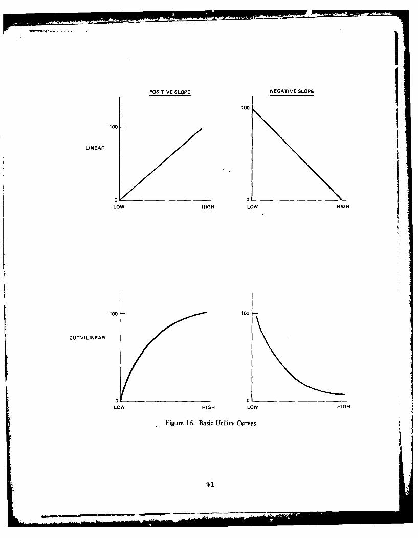
I
POSITIVE SLOPE NEGATIVE SLOPE
0 __ 0
LOW HIGH LOW HIGH
100 100
CURVILINEAR
o 0
LOW HIGH LOW HIGH
Figure 16. Basic Utility Curves
91
low utility, medium value yields medium utility, high valueyields high utility. The "linear-negative" curve is the reverse.
The curvilinear relationship reflects the law of diminishingreturns. Past a certain point, increased magnitude doesn't yielda proportionate increase in utility; below that point, utilityrapidly drops off. The "curvilinear-negative" is the reverse.
The actual curves, parameter assessments and utilities ofthe thirteen criteria are illustrated in Figure 17. "Datarequired for development," for example, was scored using a"linear-negative" curve. Alternatives requiring more data todevelop received lower utility values than those requiring lessdata. Since the top-down approach (coded as "T") requires themost data (see assessments in Table 28), it received the lowestutility value.
On the other hand, the top-down approach requires less inputdata to use than either the bottom-up or sideways approach.Since the curve used for that criterion was the "curvilinear-negative," the top-down approach receives the highest utilityvalue on that dimension.
Weighted Average Scores of Approaches
The weighted average utility scores for the three costestimating approaches are computed as shown below. Table 30contains the details of the computations.
Scorej W.U.j wherei ij
i = evaluation criterionj = alternate approachW. = weight of ith criterion
1 (see Table 28)Uij= utility value of jth approach
on ith criterion (see Table29, Figure 17, and Table 30)
The final results are as follows:
Cost Estimating Approach Average Score
Bottom-up 72.88Sideways 55.C2Top-down 50.82
The top-down and sideways approaches appear as the least
attractive for use in the PSCM, based on their significantlylower scores in the evaluation. As indicated by the relativecloseness of their scores, however, the top-down and sidewaysapproaches could possibly be utilized with equal effectivenessin developing a PSCM.
92
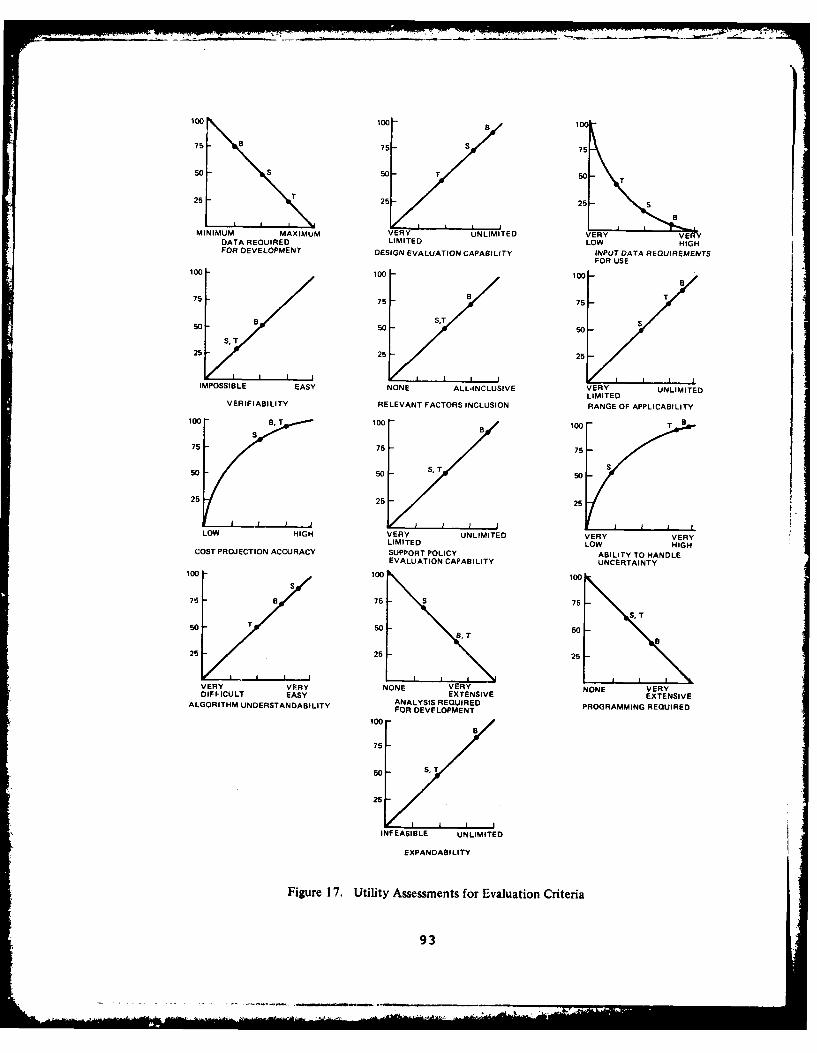
100 100- a 100
7b 75 S 75
50 -S 50 50 T
25 T 25 25 S
B
MINIMUM MAXIMUM UNLIMITED VERY VERYDATA REQUIRED LIMITED LOW HIGHFOR DEVELOPMENT DESIGN EVALUATION CAPABILITY INPUT DATA REQUIREMENTS
FOR USE100 100 100"75 -75 75/-75
SB
S0 - B0 ST S5OV5 50
25 25 25I I i I I I I
IMPOSSIBLE EASY NONE ALL-INCLUSIVE VERY UNLIMITEDLIMITED
VERIFIABILITY RELEVANT FACTORS INCLUSION RANGE OF APPLICABILITY
10 ,T10B 100 T B
75 75 75
50 50 S.T 50
25 25 25
LOW HIGH VERY UNLIMITED VERY VERYLIMITED LOW HIGH
COST PROJECTION ACCURACY SUPPORT POLICY ABILITY TO HANDLEEVALUATION CAPABILITY UNCERTAINTY
100 -100 100S
75 - a 75 - S 75 -
S, T50- T so50, 50
25 25 25
VERY VERY NONE VERY NONE VERYDIFFICULT EASY EXTENSIVE EXTENSIVEALGORITHM UNDERSTANDABILITY ANALYSIS REQUIRED PROGRAMMING REQUIRED
FOR DEVELOPMENT
100-B
76
50 S,T
25
INFEASIBLE UNLIMITED
EXPANDASILITY
Figure 17. Utility Assessments for Evaluation Criteria
93

C,0 0 0 40 N' 0 0D -T M CI fn 00 t
in 0 nI
0 Go'4 u C (4 -e V- 0' NA mA %D co V .
0 3t 0
.,jn 04 C 0 0n 0 0 0 Ln 0 C ) (n n 0~ '0n oc ('4 ('4 n In 0 N. Ln %D0 Go ko %o H 0
0,
E- 0).
0 0
V- 0 oCL D a L 0 0 o ' I 4o oC In on cn on
01-4
(L 4)
M- 0,j .1 rA 0. 0o L c 0 0 0 0D 0W mA 0 04 00 V - 1-4 C, aA a 0~ 0 0' 4D- 0 0 0Q
C.C
4J
4) 41W.q > 4 lz0 c~ 41 00
V 4)4 *-4 >
0 V *' 0 4 H VH 11 14 Uj $4 W- .
V 0 U) m' 0 4 ) V .44 4 w 0) 14 C 0 U
4V 0 .- c~ W :0 gto > 4J-l 4 -,4 4) 0 0 1.
1.4 .C .0 40 1.4 A Vi 4) V -
4J- W -4 - 4 o -4 V1 -.1.4C00 . 4 ) -4 to to. ca &., 0..00 ., 0, 4 4J WH 11 m -4 14 >
IV W 4) U 04 a 14 -. D 41 A ' 4
$V-I 0 '4 10 01 0 4 0 1j C. Ho tot, V 4 . 4) 4 0 04 L4
1. H -A 4) tri 0. r -4 1 0 v4)1 0 ( ., Ha C4 V0 .,1 t4" 0
(D H) 0) 1M I *
94

The bottom-up approach scored considerably higher than thesideways and top-down approaches. Taken individually, the bottom-up approach scored highest for eight of uhe thirteen dimensions,with significantly higher scores achieved for five dimensions:
* Data required for model development
* Design evaluation capability
* Verifiability
* Relevant factors inclusion
* Maintenance policy evaluation
The bottom-up approach scored significantly lower than the side-ways or top-down approaches on only one dimension; input datarequired for utilization. A normal bottom-up model requiressignificantly more input data than the other two approaches.This disadvantage can be overcome through good model design.
The scoring results reflect the general opinion of theevaluation panel that, due to the limited availability ofappropriate historical data on which to build a model, selectionof the bottom-up approach will result in the fewest design,development, and verification constraints for the PSCM. Thesideways and top-down approaches are considered to require muchmore data for development of the estimating relationships andalgorithms than are currently available.
CONCLUSIONS
The bottom-up approach using subtask resource/cost estimatessummed to produce the total support cost estimate representsthe most practical single cost estimating approach on which tobase the PSCM. The bottom-up approach has the advantage ofmaking good use of the limited quantitative and qualitative datacurrently obtainable, with the potential for extensive refinementas more and better data become available.
A bottom-up model could be structured basically as describedin Figure 15 on page 78 with the various initial and recurringsupport cost estimates computed from a minimal set ofinput data describing the proposed software design. Otherinput data values could be supplied as default values from thedata base supporting the model. Those default values could bea function of system type, application, etc.
The bottom-up approach can best model the avionics embeddedsoftware support cost generation process. Insufficient dataare available to adequately support a top-down approach whichcould be well-validated and accepted by the model usercommunity.
95

VIII. DEFINITION OF P TASE II ROADMAP
GENERAL
Development of a model that will effectively predictsoftware support costs requires implementation of a logical,well-defined, yet flexible modelling approach. The approachmust build upon a combination of what is... and what shouldbe... in the world of software support. In other words, theapproach must be responsive to and reflect existing softwareprocesses and achieved software performance in the real world,yet be sensitive to the positive and negative lessons learnedand the advanced concepts which will influence the futuresoftware support scenario.
To this end, as a result of efforts during Phase I of thePSCM study program, a modelling approach has been selectedwhich blends classical model development with refinementsspecifically applicable to avionics systems. The refinementsare the result of the Phase I literature search and datacollection and analysis tasks.
The selected approach is embodied in the cost modeldevelopment methodology overview presented in Figure 18. Theportrayed methodology illustrates, in simplistic form, fivefundamental tasks required in Phase II to develop and deliverthe predictive software cost model. The tasks, i.e.,
* collect data,* analyze data,* develop data base,* design PSC model, and* test PSC model,
are the subjects of subsequent major paragraphs of this reportsection, and are individually developed and discussed therein.
The methodology, basically, defines two related parallelefforts, one for design of the predictive software cost modelitself, and the other for development of the comprehensivehistorical data base upon which the model design will be based.Preliminary data organization and analyses will provide anassessment of total data base requirements as well as "workingfiles" for parametric relationship determination and algorithmdevelopment. From there, development efforts for the operationaldata base and the operational PSC model will run parallel pathsuntil the loop is again closed during the model test task. Therethe model will be tested to demonstrate that it properly reflectsits derivation from intelligence contained in the data base aswell as its software cost prediction capability.
97
PF~JJD AGS BLWM 32LMMU

S COLLECT ANALYZE DESIGN _~PSC
~MODEL
[ DEVELOP TEST
DATA PSC MODELBASE
Figure 18. Model Development Methodology.
An expansion of the methodology overview is presented inthe model development roadmap of Figure 19. This roadmapillustrates a more detailed task flow, showing relativesequences, interrelationships, and the iterative nature of thesubtasks.
The intent of the model development approach, as portrayedin the roadmap, is to:
" conduct an organized data collection effort which willbring together all currently and feasibly availablepertinent information concerning the software supportworld, including conceptual as well as process andperformance data,
* glean from conceptual studies how software should besupported in the ideal or typical situation,
understand the software support and cost estimatingprocesses that are applied in the real world inaccordance with, or in spite of, regulations andprocedures for their application,
* perform analyses of end results of the software supportprocesses, i.e., the historical cost element performancedata,
* benefit from hard lessons learned, both good and bad,from past software support experience,
consolidate this knowledge and information in acomprehensive qualitative and quantitative data basewhich can readily be updated and accessed for modeldevelopment and refinement,
98

ANALYZE DATA
[PRELIMINARY DATA ANALYSIS ]DA -NY
CAEORZ (SESDT DETERMINEDATE QUALITY/ QUANTITATIVE
DATALES PARAMETRICS
FORMULATE DETERMINEDATA BASE QUALITATIVECONCEPT PARAMETRCSI I
PELIMINARY DATA ORGANIZATIONI CREATE
PRELIMINARY 'DATA"WORKING FILES"
DEVELOPDATA BASE
I I DEVELOPORGANIZEEVALUATE "PROCESSED DATA"DATANI-0 QUANTITY FILES
OF DATAI I
EVALUATE DATA
TYPES 0 STORAGE
OF DATA REQUIREMENTS
L JII DETERMINE
DATA
ACCESSREQUIREMENTS
\0

DESIGN PSC MODEL
----- ----- ----- - ~ FTVELOP MODELIALGORITHMS
DTRIEDETERWvINE[ COSRTPA ETRINE SIGNIFICANCE C OSRITMPRAMTICHP OF PARAMETRIC AGRTM
RELATINSHIPSRELATIONSHIPS
* STATISTICALL* QUALITATIVEI
COMPAREIRELATIONSHIPS I > ~TEST/REFINETO CURRENT IALGORITHMSESTIM ATINGI
_____________________________________* PRACTICES/L* TECHNIQUES
EST'REQU
DATA
___________________________CREATE
DATA BASE OPERATIONAL*CODE DATA DATA BASE*ENTER DATA
EVALUATEDATA STORAGE/ _________
ACCESSBALTERNATIVES
REIN

SDESIGN MODEL STRUCTURE [PLEMENT MODEL
CREAE MODELSELECT ALGORITM LOIALGORITHMS ALOITM
SELECT DATAI
DTRIEACCESS METHODSDETERMINEI
ALGORITHMIMPORTANCE/ CINTZERRELATIONSHIP COSRCTRFN
i DETAI LED PSC MOO-DATA FLOWS
I0 DETERMINE INPUT/ DETERMINE
INTERMEDIATE/OUTPUT FORMAT6REQUIREMENTS REQUIREMENTS
ESTABLISH INTERFACE LREQUIREMENTS: MODEL/DATA BASE/CYBER 175
TEST PSC MODEL
AB
V ERIFY MODEL
DEVELOP CONDUCT "INTERNAL"VERIFICATION TESTINGPLAN e CONSISTENCY
* ACCURACY* ALGORITHM
PERFORMANCEFORMATS
L-----
/1
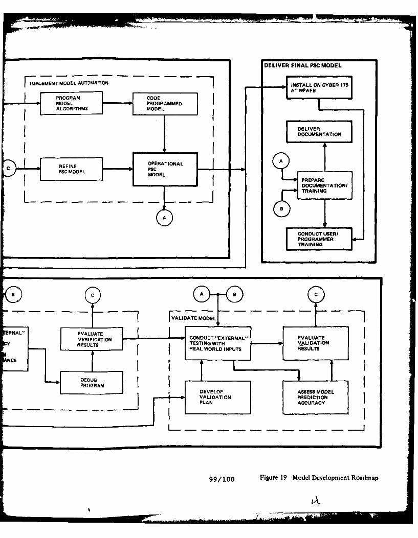
-EIE IA S OE
IPLEMENT MODEL AUT)MATION 10INSTALL ON CYSER 1761PROGRAM E CODE A PF
MODEL PROGRAMMED
ALGORITHMS MODEL [DELIVERDOCUMENTATION
c REFINE OPERATIONALAPSC MODEL CI
MODELPREPARE
EDOCUMENTATION/L ITRAINING
A B
CNUTUSER/PROGRAMMER
TRINN
VNL[ EALUATO CONDUCT -EXTERNAL" EVALUATE
V ERIFICTIO TESTING WITH VALIDATION
RESUTS IRE AL WORLD INPUTS RESULTS
ACE jDEBUG
PROGRAMDEVELOP ASSESS MODELVALIDATION PREDICTIONPLAN ACCURACY
99/100 Figure 19. Model Development Roadmap

* build a support cost prediction model, upon intelligencefrom the composite of information, which can effectivelytrade off and assess expected software support costsearly enough during program software development phasesto influence the software design, and
* verify that the model performs as intended withacceptable levels of consistency and accuracy.
COLLECT DATA
The data collection task is the solid foundation whichestablishes the degree of effectiveness achievable in developingthe predictive software cost model. Sophisticated andtechnically correct analysis and design efforts usinginadequate data will provide a rigorous and technicallyconsistent model. A model so constructed, however, will produceonly misleading results at best, because the basis for the modelconstruct is insufficient.
Collecting all data that exists in the software supportworld is not possile... or even necessary. But that which iscollected must be (1) comprehensive and complete, (2)representative of the software support universe, (3) possesssufficient quantity and quality to be meaningful, and (4) bepertinent to the task at hand. Satisfaction of these attributeswill establish the basis necessary not only for completing apredictive software cost model design, but for achieving a modeldesign that will produce effective and meaningful results.Further, the data collection task in Phase II should be orientedprimarily toward collecting the data required to develop a deeperunderstanding of the key factors identified in Section VI(especially Figure 15).
The objective of this task in Phase II must be to accumulatethe best data feasibly available so that the analysis and modeldesign efforts are optimized.
Data Types
The data to be collected should include qualitative as wellas quantitative information, categorized under the followingdata types:
ConceptualRegulatory
* Procedural* Process* Performance* Special
101

The quantitative data will include primarily historicalperformance data supplemented by special stu,Aes. Thequalitative data will focus both on 1) understanding in greaterdetail the processes of software support and cost estimatingin the Air Force, and 2) supplementing the available historicalperformance data with expert opinion in order to fillquantitative data voids.
Conceptual data is that information which, for this case,reflects what ideal support of software should be like. Theadvanced concepts set the targets to shoot for in the real worldapplications. Consideration of this type of information isnecessary due to its influence and impact in shaping the futuresoftware support situation. How, and to what degree, shouldconceptual data influence the PSC model design?
Regulatory data consist of official rules of direction,i.e., the various AF regulations that govern software support.What are they? Are they adequate? Are they effective? Whatinfluence should they have on the PSC model design?
Procedural data relate to the established step by steporder of acting to accomplish the regulations. What are theofficial procedures? Are they AF-wide or local? How good arethey? Do they accomplish the intent of the regulations? Shouldthey influence the PSC model design, and to what degree?
Process data relate to the actions or operations leadingto desired results. For this case, these data reflect how theprocesses of software support really work in the real worldbecause of, or in spite of, the regulations and procedures.How, and to what degree, should this type of informationinfluence the PSC model design?
Performance data describe the end results of the actionsand processes. What software support tasks were performed andwhat were their sizes? What were the task types? When werethey performed? What manhours were expended? What otherresources were used? What were the costs? etc. These datarepresent the recorded end results which should providequantitative parametrics for determining cause/effectrelationships and for relating to expenditures as the basis forcost estimating relationships.
Special data relate to additional information not includedin the above data types. This should include such things asopinions of experienced practitioners to provide qualitativeassessments of non-measureable software performance and otherattributes.
102

I REGULATIONS
CONCEPTS - - - - - - - . .. .- -PERFORMANCE
DATA PERFORMANCE
Figure 20. Data Type Relationships
The data from all the above categories, when collected,must provide a basis to resolve, or at least systematicallyaddress, the factors necessary to design the PSC model. Figure20 illustrates the relationship of the data types.
Data Required
A primary purpose of Phase I efforts was to identify andsize the data collection requirements for Phase II. Theresulting Phase II data collection requirements are summarizedin the following paragraphs.
The Phase II data collection task expands upon efforts begunin Phase I. There, the extent and nature of avionics softwarewithin the Air Force was determined, and specific relevant samplesoftware packages were identified for the PSCM study program(see Section III).
During Phase I, visits were made to various ALCs toidentify the specific program software data sources, and to gaininsight into general software maintenance practices and datarecording activities within AFLC (see Section V). Preliminarysample data were collected on selected software packages, andspecific sources were identified for additional pertinent OFP,EW and ATE data collection in Phase II. Detailed informationfrom the Phase I visits is contained in Volume II of thisreport.
Several conceptual studies/projects were identified duringPhase I (Table 31) which relate to the software world. ThePhase II task is to investigate them (and any others identifiedduring Phase II) to determine if and how they may influence thePSCM study and the resultant PSC model design. Their scope maybe much broader than that of the PSCM program, but theirpotential impact must be considered.
103

TABLE 31. DATA REQUIRED - CONCEPTUAL
Data Type Source Comments
Digital Avionics AFWAL/AA On-golng softwareInformation System development/analysis
projects and studies.Rand Study Rand Broader in scope, but
may influence/impactRADC Data Bank RADC PSC model effort
Associated studies Various
Table 32 identifies primary regulatory information andstandards representative of the policies and requirements imposedupon the management, use and support of avionics software. Theregulatory data, collected during Phase I, is not necessarilylimited to software and computer related resources, but providesdirection that encompasses software aspects. The list is notexhaustive, but is meant to include primary top-level regulatorydata and to provide a representative cross-section.
Procedural data that implement the regulations andstandards are identified in Table 33. Again, the list isrepresentative and not exhaustive. The plans, procedures andoperating instructions are those generated and used by theorganizations that operate and support the avionics softwareand associated computer resources. Copies of these documentswere collected during Phase I.
Regarding process data, it will be important to increaseunderstanding of the real world processes that lead toestablishing software support requirements and providing resultantresources. In this regard, Phase II emphasis should be placedon gaining insight into several key AF processes, i.e.,
* the user and ALC software change requirement establishmentand change selection process,
* the AFLC/ASD support resource planning process, and
* the AFWAL/AA cost analysis process.
How does the software user evaluate and establish the needsfor changes to the software? How are the requirements transmittedto the supporting ALC? From all stated requirements, how doesthe user/ALC select those changes to be implemented? Are theselections constrained by budgets or other ceilings imposed onthe resources and services allocated for software support? If
104

4TT
TABLE 32. DATA REQUIRED - REGULATORY
DoD Directive 5000.29 Management of Computer Resources inMajor Defense Systems
- establishes DoD policy for the management and control ofcomputer resources during the development, acquisition,deployment and support of major defense systems.
DoD Directive 5000.31 Interim List of DoD Approved HighOrder Programming Languages (HOL)
- specifies the High Order Programming Languages that areapproved for the development of software for new majorprograms.
MIL-STD-480 Configuration Control - EngineeringChanges, Deviations and Waivers
- sets forth requirements for maintaining configurationcontrol of configuration items; requirements apply tocomputer software that is designated as a configurationitem.
MIL-STD-483 (USAF) Configuration Management Practicesfor Systems, Munitions, and ComputerPrograms
- establishes uniform configuration management practicesthat can be tailored to all USAF systems and configurationitems, including those procurred by USAF for otheragencies.
MIL-STD-490 Specification Practices
- establishes format and content requirements for programpeculiar items, processes and materials; includesrequirements for computer program development specifica-tions and computer program product specifications.
AFR 800-14 Vol I Management of Computer Resources inSystems
- establishes overall policy for the acquisition and supportof computer resources; assigns management responsibilitiesto HQ USAF, AFSC, AFLC, ATC, Air University and usingactivities.
AFR 800-14 Vol II Acquisition and Support Proceduresfor Computer Resources in Systems
- contains procedures for implementing the policies includedin Volume I.
105

TABLE 32. DATA REQUIRED - REGULATORY (Continued)
MIL-STD-1521A (USAF) Technical Reviews and Audits forSystems, Equipments and ComputerPrograms
DOD Standard 7935.1-S Automated Data Systems DocumentationStandards
- provides guidelines for the development and revision ofthe documentation for computer.. .programs.
AFLCR 66-27 Automated Support of Automatic TestEquipment Software
- establishes policy, assiqns responsibility, and providesprocedures pertaining to... requirements for automatic dataprocessing resources when required for the organicpreparation, maintenance and management of ATE software.
AFLCR 66-37 Management of Automated Test Systems
- establishes policies for automatic test system managementand defines responsibilities; applicable to AFLC activitiesassociated with management, use, and support of ATE hard-ware and software; used in conjunction with AFLCR 6b-27to provide policies and procedures for support of automatictest system software.
s-, how are the constraints set? Inherent in understanding thechange selection process is understanding how individual softwarechange criticalities, complexities and costs --re established.
How does the AFLC/ASD support resource lanning processoperate? Traditionally, software support resource allocationsare determined early in the software development phase. How isthis currently accomplished? These allocations are then usedto select (constrain?) the individual software changes to beimplemented as part of software support. How do the ALCsinfluence the allocations of software support resources?
What does AFWAL/AA currently use as the basis for theirprogram cost analyses, especially as they relate to softwaresupport? How does the cost analysis process work?
Do these planning and resource establishing processesoperate in a coordinated manner, or ara they basicallyindependent of one another? How formal are they? Do they differamong programs? Do they follow regulations and procedures?
106
4 .

TABLE 33. DATA REQUIRED - PROCEDURAL
Document Source Title
F-15 CRISP SPO F-15 Avionics Software ComputerResources Integrated Support Plan
F-16 CRISP SPO F-16 Multinational Computer(F-16-I001/I/2) Resources Integrated Support Plan
Planning Guide SA-ALC Automatic Test Equipment Acquisi-
tion Planning Guide
CM Plan OO-ALC OFP Configuration Management Plan
MMOI 800-2 SA-ALC Preparation and Use of AFLC Form
75, Computer Program ConfigurationSub Board Item Record
MMOI 800-14 WR-ALC Acquisition, Management, and Supportof Computer Resources in Systems(Software and Associated Equipment)
MMROI 800-01 WR-ALC Software Change Processing/Configuration Management for EWSystems
MMROI 800-03 WR-ALC System Verification Test Proceduresusing Simulation and Analysis TestSystems
MMECOI 65-2 WR-ALC Configuration Management forAvionics Integration SupportFacilities
MMECOI 800-14 WR-ALC Software Change ProcessingProcedures for Operational FlightPrograms
O/S CMP SM-ALC Operational/Support Configuration(F/FB-IlI) Management Procedures for F/FB-lll
Operational Software
O/S CMP OO-ALC F-16 Multinational(F-16) Operational/Support Configuration
Management Procedures
107

_ _ _...... ---....... -- ... - - q i -
TABLE 33. DATA REQUIRED - PROCEDURAL (Continued)
Document Source Title
O/S CMP SA-ALC Operational/Support ronfiguration(ATE) Management Procedures for ATE
Software
Work Units WP-ALC Computer Resources (MMEC) WorkCenter-Time Standard Descriptions
Testing Guide WR-ALC Software Testing Guideline(Preliminary)
Regarding the AF processes, these are the types of questionsthat need to be answered. The properties related to softwaresupport must be identified and, if possible, quantified forconsideration in the PSC model development. Understanding theseprocesses will require extensive interfacing with the AP managersand analysts directly involved with their conduct.
Available performance data are identified in Table 34, andrequired performance relationship data are identified in Table35. Since avionics software support is a fairly new AFLCresponsibility, software support process and performance dataare not currently well documented, but are developing out ofnecessity. As discussed in Section V, the A-7 and F/FB-11I familyof software packages are the only OFP software systems which cancurrently provide actual support resource requirement and costdata within AFLC. The F-15 and F-16 software packages will beexcellent representative data sources in the future. WR-ALChas begun to work on F-15 OFP changes, and should have some dataavailable in the 1981 time frame. 00-ALC is currently manneO toorganically support three F-16 OFPs, but is only performing V&Vof contractor changes at this time. Again, they should have somedata available in 1981. However, the quantity of hard performancedata available for estimating relationship analysis anddevelopment during Phase II may be somewhat limited.
In any event, that performance data which was collectedduring Phase I must be updated and supplemented to proviez ascomplete a package as possible on all targeted systems. Thesedata will comprise the primary bases for establishing estimatingrelationships for model development.
108

TABLE 34. REQUIRED DATA -PERFORMANCE
System
Data Type A-7D F/FB-lll F-15 F-16 EW ATE
Number of X X X X X XChanges
Manhours Aggregate X? V&V only X XPersonnel Salary X X x X x Xand overhead
Facility Size x x X X??Facility Cost????? ?Support Hardware x X X x X?Cost
Support Software ??????Cost(Acquisition)
Documentation???Cost(Acquisition)
Flight Test:
Aircraft Cost X x X X X n/a(Acquisition)
Flight Hours x x ? xX n/a(FR)
Cost/FH X x X X X n/aRange Hours ????? n/a(RH)
Cost/RH ?7 n/a
Data Source(s) OC-ALC SM-ALC WR-ALC 00-ALC WR-ALC SA-ALCMMECZA MMECP MMEC MMEC MMRR Various
MMET WR-ALCACDCS MMECT
Legend: X = available?= possibly available
n/a = not applicable
109

TABLE 35. DATA REOUIRED - PERFORMANCE RELATIONSHIPS
Change volume/rateSoftware reliability
Factors affecting avionics software reliabilityRequirements changes
Factors affecting changes
Manhours per changeProductivity
Factors affecting productivity, e.g.,Support hardwareSupport softwareDocumentationPersonnel experience/trainingIncentives
ModifiabilityProgram structure
SizeComplexityArchitectureLanguageetc.
Hardware characteristicsMemory fillTiming requirements
Size of changeApplication/function affectedPerformance requirementsAnalysis requirementsV & V requirements
Amount of support hardwarePrime system hardwareAnalysis requirementsV & V requirements
Amount of support softwareSupport hardwareAnalysis requirementsV & V requirementsAutomation of support process
Hours of Flight test time/range timeV & V requirements
Cost/hr of range test timeExtent of instrumentation
V & V requirements
Efficiency factor (productive manhour/year)Holiday/sick leaveAdministration requirementsTraining requirementsetc.
110

Table 36 identifies types of special data that should becollected in Phase II, if possible. Phase I visits indicatedthat performing organizations sometimes conduct "pocket" studiesand analyses concerning specific software related problems thattrouble their operation. They are often accomplished in additionto their normal, routine data recording activities that reflectperformance data. Data sought from these sources should besolicited and collected. Also, qualitative information frompractitioners should be solicited in areas where no hard dataare available.
TABLE 36. SPECIAL DATA
Manhours per type of software change
Relationship of changes to underlying requirements
Programmer productivity
Capacity vs. workload in the software support center
Manhours related to software complexity
Relationship of changes to test requirements
Relationship of changes to program maturity
Manhours related to skill/training levels
Qualitative information
Having completed collection of the required data from alldata categories identified above and in the Model DevelopmentRoadmap (Figure 19), the Phase II analysis and PSC model designefforts can begin.
ANALYZE DATA
As stressed earlier in this section, the collection of datais considered foundational to the PSC model design effort. Whilethe data analysis task provides the parametric relationshipson which to design the PSC model, the parameters, theirrelationships and their significance are wholly dependent uponthe quantity and quality of intelliqence contained in thecollected data.
Iii

The data analysis task, therefore, must ferret out thatintelligence, make an assessment of its completeness and quality,and, given that it is adequate, determine the meaningfulrelationships of the parameters and their significance for usein constructing the PSC model. If, for any reason, theintelligence is determined to be inadequate for any aspect ofmodel development, the data analysis task must identify the areaof inadequacy early enough to enable, in coordination withAFWAL/AA, timely collection of additional requisite data. Thecurrently identified data collection task should be fullyadequate, however, and the following discussions are based onthat assumption.
Refer to the Model Development Roadmap (Figure 19). The
primary objectives of the data analysis task should be to:
* uncover the unbiased parametric relationships evidencedin the collected data,
* determine their suitability for use in the PSC modeldevelopment, both quantitatively and qualitatively,
* use them to substantiate and/or refine the factors andrelationships postulated on the basis of Phase I findings(refer to Figure 15 in Section VI), and
* provide them as candidates for development of modelalgorithms.
In order to accomplish these objectives, the roadmapillustrates that an orderly examination and analysis of thecollected data is required. The first step of this process isto organize and categorize the data to perform a preliminaryevaluation of the data attributes of comprehensiveness,completeness, representativeness, quantity, quality andusefulnesss. The next step is to create preliminary data"working files" which become the fodder to supply the demandof the detailed data analysis and algorithm developmentprocesses, and the basis for development of the comprehensivehistorical data base. The "working files" are envisioned toconsist of both computer based quantitative performance datafor easy uutomated analytical access, and non-computer basedinformation for qualitative considerations.
The final step is to use the "working file" data to performappropriate statistical and qualitative analyses to identifythe most prominent and most significant parameters and theirrecurring interrelationships for subsequent use in modelalgorithm development. An interesting branch of this effortwill be to compare the unbiased parameter relationships soderived with practices and techniques currently in use, and withother preconceived concepts.
112

Parameter/Parametric Relationship Determination
Figure 15 on page 78 in Section VI presents a view of thesoftware support cost generation process based on results ofPhase I efforts. The Phase II data analysis task should bedirected toward supporting, refining and/or modifying the factorsand variables and their relationships as illustrated therein.In the figure, the relationships between specified intermediatevariables and outputs are fairly well understood, but theinfluence of the key input variables is not well understood.The analysis task must be oriented toward developing a deeperunderstanding of all key factors and their relationships. Theanalysis task must also "look ahead" in an attempt to discernhow the software support process may evolve over the next severalyears in order to assure that other critical factors, perhapsnot yet evident, are not left unconsidered.
The main thrust of the data analysis task should centerabout the quantitative data obtained primarily from theperformance data category (Tables 34 and 35), and anyadditional quantitative data available from the special datacategory (Table 36). These data should provide the hard coreof intelligence from which. parametric relationships can bederived using multivariate analysis techniques.
Secondary, but still very important, emphasis should beplaced on the qualitative information emanating from theconceptual, regulatory, procedural, process and special datacategories. These are the data which provide flavor and finetuning for the parametric relationships and their significance,and for subsequent model algorithm development and mode]structure design. Where possible, the qualitative data shouldbe content-analyzed, as part of the data analysis process, totransform the inherently qualitative nature of the informationinto data that are amenable to numerical manipulations. Thiswill not always be possible.
The overall goal of the data analysis must be to sortthrough the "working files" to identify the key factors and theirinterrelationships in an unbiased manner. Thesefactors/interrelationships, then, provide the basis necessaryto formulate the PSC model. From a statistical standpoint, theanalysis needs can be satisfied using multivariate analysistechniques, of which the following generic areas should beconsidered:
* factor analysis,
• canonical, partial and multiple correlation analysis,and
* linear discriminant analysis.
113

Selection of the data analysis technique(s) in Phase IIshould depend upon the preliminary assessment of attributes ofthe collected data, especially the quantity and quality. Thecorrelational techniques, which are typically used when the dataset contains a set of predictor variables and a set of outcomevariables, should comprise the primary analysis tools.
DEVELOP DATA BASE
The operational data base must contain parametric dataappropriate for all expected applications of the operationalPSC model. The set or sets of parametric data to be used witheach model application should be keyed by the inputcharacteristics of the type of software whose support costs arebeing predicted, and should be automatically accessed by themodel for computational use.
Development of the data base should be an evolutionaryprocess starting with the raw quantitative and qualitative datacollected during the data collection task, and culminating withan operational data base for use with the PSC model. The database development process should be an effort parallel (butintegrally related) to the data analysis, algorithm development,and model structure design subtasks.
The data base development is envisioned as comprising threebasic phases: creating preliminary data "working files,"developing "processed data" files, and developing the operationaldata base. This concept is illustrated in Figure 21.
COLLECTEDI1DATA SET PSC I
DATA "PRCGSE DATA" OPEATIBASE
II
DATA ALGORITHM MODELANALYSIS DEVELOPMENT STRUIGN S .
DESIGN
Figure 21. Data Base Development Concept
114
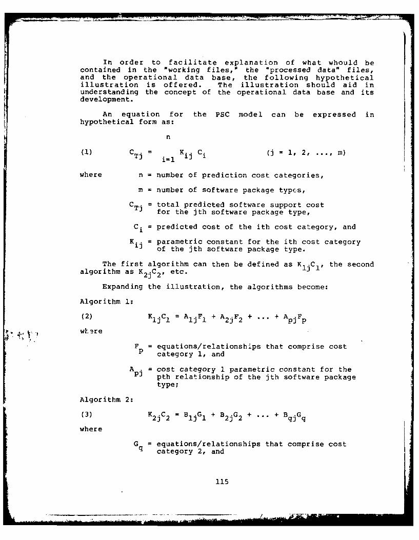
In order to facilitate explanation of what whould becontained in the "working files," the "processed data" files,and the operational data base, the following hypotheticalillustration is offered. The illustration should aid inunderstanding the concept of the operational data base and itsdevelopment.
An equation for the PSC model can be expressed inhypothetical form as:
n
(1) CTj i=l K1 C (j = 1, 2, ... , m)
where n = number of prediction cost categories,
m = number of software package types,
CTj = total predicted software support costfor the jth software package type,
Ci = predicted cost of the ith cost category, and
Kij = parametric constant for the ith cost categoryof the jth software package type.
The first algorithm can then be defined as KljCI, the secondalgorithm as K2jC2, etc.
Expanding the illustration, the algorithms become:
Algorithm 1:
(2) K1 jC1 = AIjF 1 + A2 jF2 + ... + ApjFp
'*, v, whsre
F = equations/relationships that comprise costP category 1, and
A . = cost category 1 parametric constant for theAj pth relationship of the jth software package
type;
Algorithm 2:
(3) K 2j C2 = BjG1 + B2 jG2 + ... + BqjGq
where
G = equations/relationships that comprise costq category 2, and
115

B = cost category 2 parametric constant for theqth relationship of the jth software packagetype;
and similarly for n algorithms representing all cost categoriesto be predicted.
Further expanding the illustration, the functions comprisingalgorithm 1 become, for example:
(4) F 1 = af(x) + a2 f(y) + a 3 f(xy) +
(5) F 2 = b 1 f(x,y) + b 2f(y,z) + b 3 f(z) +
(6) F3 = clf(x'Y'z) + c 2 f(xz) + c 3 f(yz) +
Fp =
where f's = functions of elemental input variable(s), and
a's, b's & c's = parametric constants for thefunctions (f).
The same type of expansion can be made for algorithms 2 throughn.
With this hypothetical illustration as a basis, let usdefine the concept of the data base development process.
Preliminary Data "Working Files"
These files should contain the categorized and organizedraw data elements from the data collection task, bothquantitative and qualitative. These files are the elementalvalues of x, y and z illustrated in equations (4), (5) and (6),and the intelligence that enables determining theirrelationships.
The "working files" re envisioned as the data elements fromwhich the (F) relationships and the values of the a's, b's andc's are derive in the detailed data an-alysis subtask. Referto the roadmap of Figure 19. Some of the values (a's, b's orc's) may be standards, such as SN/flight hour; others couldbe derived along with the (f) relationships from, for example,multiple correlation analysis of various data lements.
"Processed Data" Files
These files should initially contain the sets of valuesfor a's, b's and c's provided from results of the detailed dataanalysis subtask. From these values and from additional
116

intelligence in the "working files," the relationships C, andthe values of A's, B's, ... , and K's (equations M, (2) and(3)) are derived as part of the detailed data analysis andalgorithm development subtasks. These values should then beadded to the "processed data" files.
The values and/or forms of the A's, B's, ... , and K'srepresent the relative importance and the interrelationship ofthe functions that make up the algorithms and of the algorithmsthat make up the cost categories. Some of the values may bederived by knowledgable, systematic interpretation andapplication of qualitative data, but all should have traceablebases.
Operational Data Base
Simply, the operational data base should contain all thedeveloped parameter sets from the "processed data" files,properly structured and coded for automatic access and use bythe PSC model.
Data Base Concept Summary
The raw data "working files" will be the collected dataelements from which parametric relationships (F's, G's, etc.)and parametric constants (a's, b's, c's, etc.) are derived duringthe detailed data analysis subtask.
The "processed data" files should contain the parametricconstants (a's, b's, c's, etc.) from which the cost categoryrelationships (C.) and the values of their modifiers (A's, B's,
and K's) ar4 derived during the detailed data analysis,algorithm development, and model structure design subtasks (referto the roadmap of Figure 19).
The operational data base will contain the formalizedstructure of the parametric data sets developed within theprocessed data files, keyed for automatic access and use bythe PSC model.
DESIGN PSC MODEL
The model design effort should be the foc,,' vint of thePSCM development program. This effort must formulate the resultsof the data analysis task, based on the historical data recordedin the PSCM data hase, into a computer based PlCM. As shownin Figure 19, model desiqn should encompass three major designsubtasks: algorithm development, model structure design, andmodel automation implementation.
117

Algorithm Development
Algorithm development starts with the set of parametricrelationships derived during the data analysis efforts, shapesthem into candidate algorithm forms, and culminates with theselection of the set of algorithms to be used in structuringthe software support cost prediction model. This set ofalgorithms, properly structured, forms the software support costgeneration system.
The developed algorithms should reflect and encompass thefactors and relationships indicated in Figure 15 in SectionVI, dynamically reinforcing/modifying them as the analysissuggests. The illustrated system is a network of complexrelationships between three postulated types of data, namely,inputs, intermediate values, and outputs. Inputs refer to thedata required by the software designer/engineer early in theprogram life cycle, characterized as data reflecting prime systemhardware, prime system software and requirements changes.Intermediate variables specify such things as the degree ofsoftware maintainability and support center productivity, andquantify software and hardware support requirements. Outputsrefer to the major cost categories of software support cost.
Algorithms describing the network of data relationshipsmust be constructed from the basic set of parametric relationscompiled during the data analysis effort. However, sincequantitative information may be limited in some areas,supplementing subjective data reflecting the opinions andsuggestions expressed by the software professionals should beused when required. AFLC software professionals can be aninvaluable souce of the information needed to quantify anAmeasure qualitative software characteristics.
The algorithms generated during the Phase II study willprobably have the form:
INTERMEDIATE VARIABLF = f (INPUT),or OUTPUT = f (INPUT, INTERMEDIATE VARIABLE).
Algorithm development, then, requires a certain degree ofparameter definition standardization and the establishment ofparameter quantification methods.
Each newly constructed algorithm must undergo a test andrefinement process. Only those algorithms should be consideredthat are sensitive to the change in direction and magnitude ofthe independent parameter. The final algorithm form should bethe one yielding the best mathematical correlation with minimumerror. A concerted effort must be made to assure modelcompleteness while eliminating costing redundancy to prc-idethe set of final algorithms for PSCM implementation. Standard
118

rates and default values needed to compute intermediatevariables, cost drivers and cost predictions must be part ofthe operational data base.
The above approach to algorithm development should resultin a model that uses data readily available during the earlysoftware life cycle to predict software support costs. Inaddition, by computing the intermediate variables, the modelwould allow the software designer to evaluate the proposedsoftware design in terms of software maintainability.
Model Structure Design
Structuring the model design requires determining therelative importance of the selected algorithms and theirinterrelationships, and combining the algorithms into a completedynamic mathematical representation of the PSC model. Further,the subtask requires matching the mathematical nature of themodel to the target computer characteristics.
The resulting model design should reflect and conform to
user-oriented needs which include:
" Self-containment in the sense that minimal userparticipation is required to operate the model,
" Traceability of all cost estimates,
" Acceptable levels of accuracy,
" Adaptability for a wide range of avionics programs in thesense that changing technology does not necessitatereprogramming, and
" Modifiability to permit rapid and effective updatingof algorithms and data input/output.
The set of algorithms resulting from the algorithmdevelopment subtask is necessarily the key driver of the modelstructure design process. Data requirements analyses ofindividual algorithms, and of the set of algorithms as a unit,must identify all parameters needed to compute the softwaresupport cost estimates. This list of parameters must includestandard costs and rates and well as parameters which vary fromsystem to system.
Model output reports also impact the model parameter list.These reports must present the computational results in an easilyunderstood format. Parameters must be defined in order toprepare an adequate set of cost reports. These reports shouldinclude labeled cost summaries, cost profiles, and optionally,the intermediate variables and the user's input data. Thefollowing list of reports illustrates typical basic information
119
I __

a user needs to interpret model cost estimates and performsoftware design tradeoff analyses:
Input Reports should include a list of the user suppliedraw data and the computer interpreted input data setdefault values (if any). These reports should present thecomplement of parameter values used by the model such as:
* User's raw input data* Model default values* Total input data set used to compute cost estimate* Ground rules and assumptions
Output Reports should present the results of the modelcomputations. The reports should include model computationsin varying degrees of detail, such as:
* Cost summary; total support cost* Cost estimate for each major algorithm* Cost profile; total and major algorithms* Detailed cost estimates* Intermediate computation results
The combination of input and output reports must provide therequired traceability for model calibration and verification.
The parameters needed for computation and report generationshould be analyzed and used to generate a PSCM Dictionary. Thedictionary could contain parameter definitions andcharacteristics (for example, $/hour as the units characteristicof a parameter representing labor rate.) The dictionary mustensure compatilility of parameters used in more than onealgorithm.
A suggested concept of data flow for the PSCM design is
presented in Figure 22. Major data interfaces are highlightedand include those between the data sources (user and PSCM rataBase) and the computer program; br'ween the various programmodules (data access and interpretation, cost computations, andreport generation); and between the model and the user. Dataflow diagrams serve to highlight data requirements andcommonality of data between the model components. Detailed dataflow diagrams zhould be generated to aid designing the optimalmodel structure.
A CYBER 175 computer at Wright-Patterson Air Force Baseis the target computer for PSCM use. Since model structure isinfluenced by the programming languages and data managementsystems supported by the development and target computers, PSCMdevelopment should be accomplished on a target computer type.Developing the PSCM on a CYBER 175 supporting the sameprogramming languages and data management systems should ensurecompatibility ar- minimize the effort required to transport themodel from the development conputer to the target computer.
120

[ PSOMODEL -
USER INPUT DATA ACCESS COMPLETE
AND DATA SETINTERPRETATION
COMPUTAT IONI ANDFORMATTING
ON-GOINGDATACOLLECTION HISTORICAL OUTPUT
REPORTS
Figure 22. Basic Data Flow
Structure of the algorithms, data requirements andinterfaces, programming language, and data access methods shouldbe the basic elements of the model design.
Model Automation Implementation
The implementation subtask requires programming and codinoof the mathematical representation of the PSC model. This isthe final transition from a "paper" model to a computer-residentmodel.
Detailed program flowcharts must be developed from thestructured model design, and coded using the requisiteprogramming language. The program should then undergo iterativedebugging to assure program internal correctness and consistencywith respect to the "paper" model.
Corrections and refinements to the model should then bemade in accordance with results of verification and validationtesting. The process will constitute iterative model testingand re-design until an operational PSC model demonstratingdesired results is achieved.
1
121

TEST PSC MODEL
The model testing process must play the primary role inestablishing PSCM credibility. Model testing should be perfomedin two phases, model verification and model validation.Verification measures the internal consistency of the model,the extent to which it produces expected results based upon knowninputs and pre-calculated outputs, and whether it correctlyprovides the desired output formats. Validation assesses theprediction accuracy of the model in the "real world" using dataother than that from which the model was derived, if possible.The verification and validation (V & V) testing should beiterative in nature, providing feedback for refining the designof the operational PSC model and corresponding operational database. This testing and feedback feature is illustrated in theroadmap of Figure 19.
Model Verification
A PSC model verification plan must be generated whichdescribes the verification testing methodology, providesverification test procedures, details criteria for use inevaluating verification test results, and provides for feedbackinto the PSC model design.
Inputs to the model for verification testing should be theinput set of characteristics which describe one of the specificsoftware packages collected for the study. The PSC model wouldthen automatically interface with the operational data base toselect and use those parameter values appropriate for the in-testsoftware package type, and compute the predicted support costs.Results should then be compared with known pre-computed values,and with actual support cost experience for the specific softwarepackage. These comparisons should then be evaluated to determinewhat refinements, if any, need to be made to the model designand to the operational data base. The test should be repeateduntil the evaluation criteria are satisfied.
The verification test should be applied to each softwarepackage type identified and contained in the operational database.
Model Validation
For model validation, a validation plan must be developed.The plan must be similar to the verification plan, but shouldprovide for inputs from sources other than those used toconstruct the PSC model and operational data base, i.e.,"external" inputs. However, this may not be readily Achievablesince additional "external" data may not be available. Mostof !:he appropriate relevant data may have been collected andused for determining parameter values and designing the model.
122

However, one or more additional software packages not inthe collected sample should be identified, if possible, forvalidation testing purposes. The package(s) should to berepresentative of the package types included in this study.
Having accomplished this, validation testing will beconducted in a manner similar to verification testing, but withthe input set of characteristics describing the "external"software package. The model would again select and use theappropriate set of parameter values from the operational database, and compute the predicted support costs. Again, modelresults should be compared with actual experience for the"external" software package (to the extent it is available),and refinements should be made to the model as appropriate.
If additional "external" software packages are not availablefor validation testing, alternate validation testing techniquesshould be considered.
One alternate approach might be to exercise the model usingextreme values in the set of input characteristics to determinemodel behavior under such conditions. This technique couldprovide insight into the reasonableness of the model, and aqualitative assessment of confidence to be placed in itscomputations.
A second alternative might be to develop hypothetical,representative software package characteristics, in cooperationwith AFAL, and compute all intermediate and output values forjoint evaluation. These values could then be evaluated for"reasonableness" by experienced software engineers within AFLC.While this approach would be highly qualitative in nature, itwould provide a measure of whether the model could and shouldbe used for trade study purposes, and whether it provides resultswhich appear to be "correct."
Hopefully, additional "external" data will be available,and alternate verification approaches will not be required.
The overall objectives of the V & V testing should be toprovide fine tuning for the model design through iterativefeedback, and to demonstrate:
* ease of model use, i.e., operation with minimal inputdata sets,
* proper model interface with the operational data base,
123

* computational accuracy, and
* software support cost prediction capability.
DELIVER FINAL PSC MODEL
The final task in the development of the PSCM is thedelivery of the model to AFWAL/AA at WPAFB. This involves threesteps: installation on the AF CYBER 175 computer, productionof final documentation, and training of specified users.
Installation
The model must be installed on the CYBER 175 computer atWPAFB and throughly checked out to assure its properfunctioning. This checkout should include a limited rerun ofselected validation tests to verify that the model produces theproper results.
Documentation
All documentation necessary for understanding andmaintenance of the model must be developed and delivered to thecustomer. This documentation should include:
" Programmer's Manual - Description of model theory of
operation, rationale for algorithms, model structure,flowcharts, code listings, data base description, dataitem dictionary, and details of CYBER 17a implementation.
* User's Manual - Description of model theory of operation,data item definitions, description of model input processand running procedure, and limitations of model.
* Test Report - Description of V&V test plans, and resultsof tests.
Training
In addition to a general briefing to the AF project engineerand other interested persons, specific training should beconducted as follows:
* Programmer Training - A one-day training session for
the individual(s) designated as the responsible prog-rammer(s) for the Predictive Software Cost Model.
* User Training - Two half-day sessions for thoseindividuals designated as users of the PSCM.
124

ESTIMATE OF RESOURCE REQUIREMENTS FOR PHASE II
Estimates of personhours and other resources required forconducting the Phase II tasks identified in the PSC modeldevelopment roadmap are presented below. The tasks to beperformed are:
• collect data* analyze data* develop data base* design PSC model* test PSC model• deliver PSC model
A brief description of each task is presented along with the
estimate of resources required.
Collect Data
The data collection task requires a significantly largeexpenditure of effort since it is foundational to the performanceof the rest of the Phase II tasks. It will be necessary to visiteach ALC, WPAFB and RADC to obtain additional availablequantitative data (sometimes by manual file search), and toconduct in-depth interviews with software professionals to obtainprocess and other qualitative data.
At each ALC: as a minimum, two two-person trips will berequired. For each trip, at least one week will be requiredto collect additional identified quantitative and qualitativedata, plus one week after returning home in order to compileand summarize the collected data. Total of 40 personweeks.
At RADC: one two-person trip should be made to obtain theirdata which will be useful in helping to understand goneralsoftware relationships. In particular, their data on softwarereliability should be examined. Again, one week at RADC plusone week after returning home is estimated for the two persons.Total of 4 personweeks.
At WPAFB: three two-person trips will be required. Twotwo-person trips of one week duration will be for programcoordination; one two-person trip will be to study the AFWAL/AAcost estimating process (one week at WPAFB plus one week afterreturning home). Total of 8 personweeks.
125

The total estimated labor requirements for the datacollection task are:
Number ofPerson Trips Destination Personhours
4 O0-ALC 3204 SA-ALC 3204 OC-ALC 3204 SM-ALC 3204 WR-ALC 3202 RADC 1606 WPAFB 320
28 2080 Total.
Commensurate travel expense will be required.
Analyze Data
The data analysis task begins with the preliminaryorganization and evaluation of the total collection of data inall its forms to create data "working files", and proceeds toperform detailed statistical and qualitative analyses todetermine the functional forms of the various candidateparametric relationships for software support cost estimating.
During Phase I, personhours required for data analysis wereslightly less than those required for data collection, but nodetailed statistical analysis was performed. It seems reasonableduring Phase II, therefore, to require slightly more than thequantity of personhours estimated for data collection, i.e.,2080 hours, plus 10%, or 2288 hours. In addition, computer timewill be required to perform the analyses, estimated to be 6 CPUhours (based on Hushes use of Amdahl 470; this can vary widelydepending on the computing facility used).
Develop Data Base
This task involves establishing the data base structurerequired to support the PSC model, creating the historical database (including coding and entering data), and associateddebugging efforts. Labor requirements are estimated to be:
Personhours
Data base structure 160Create data base 80Debug 40
280 Total
Required computer time is estimated to be 0.4 CPU hour (againbased on use of Amdahl 470).
126
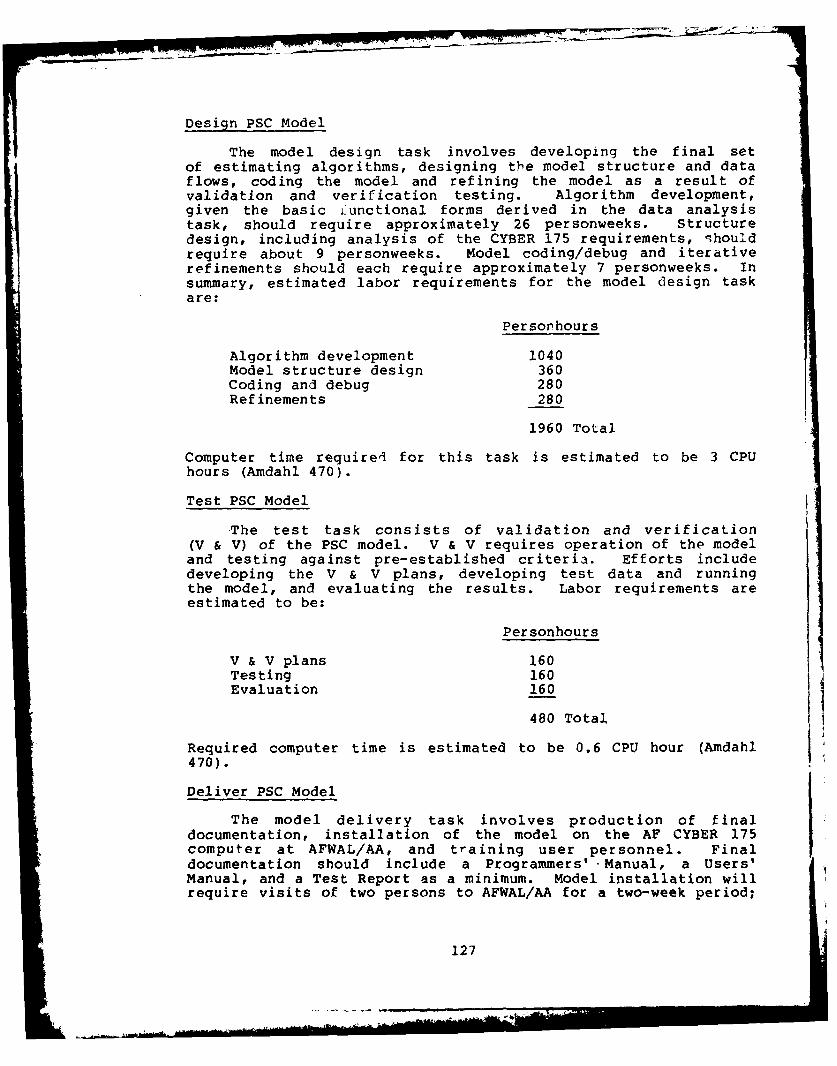
Design PSC Model
The model design task involves developing the final setof estimating algorithms, designing the model structure and dataflows, coding the model and refining the model as a result ofvalidation and verification testing. Algorithm development,given the basic Lunctional forms derived in the data analysistask, should require approximately 26 personweeks. Structuredesign, including analysis of the CYBER 175 requirements, qhouldrequire about 9 personweeks. Model coding/debug and iterativerefinements should each require approximately 7 personweeks. Insummary, estimated labor requirements for the model design taskare:
Per son hours
Algorithm development 1040Model structure design 360Coding and debug 280Refinements 280
1960 Total
Computer time required for this task is estimated to be 3 CPUhours (Amdahl 470).
Test PSC Model
The test task consists of validation and verification(V & V) of the PSC model. V & V requires operation of the modeland testing against pre-established criteria. Efforts includedeveloping the V & V plans, developing test data and runningthe model, and evaluating the results. Labor requirements areestimated to be:
Personhours
V & V plans 160Testing 160Evaluation 160
480 Total
Required computer time is estimated to be 0.6 CPU hour (Amdahl470).
Deliver PSC Model
The model delivery task involves production of finaldocumentation, installation of the model on the AF CYBER 175computer at AFWAL/AA, and training user personnel. Finaldocumentation should include a Programmers' Manual, a Users'Manual, and a Test Report as a minimum. Model installation willrequire visits of two persons to AFWAL/AA for a two-week period;
127

access to the AF CYBER 175 computer on an expeditious basis willbe required during that time period to effect the modelinstallation. Training will require two personweeks fordevelopment of training materials, and one week at AFAL forconduct of the training.
The total estimated labor requirements for the modeldelivery task are:
Number ofPerson Trips Destination Personhours
Documentation* Programmer's Manual - 700* User's Manual 360* Test Deport - 200
Model installation 2 WPAFB 160Training 1 WPAFR 120
Total 1540
Commensurate travel expense will be required. Computer time(CYBER 175) during model installation must be provided by theAir Force.
Resource Requirements Summary
The preliminary estimate of resource requirements forperforming Phase II efforts is summarized in Table 37. Totalengineering labor (8628 personhours) constitutes slightly morethan 4.5 person years of effort; associated clerical support isestimated at an additional 10% of engineering effort. ODCrequirements for travel must be commensurate with identifiedperson-trips for data collection and model delivery tasks. ODCrequirements for computer time reflect CPU hours using Hughes'Amdahl 470 computing facilities; use of other computer facilitieswould require an equivalent amount of computer resourcerequirements.
PHASE II RISKS
As with all worthwhile endeavors, conducting the Phase IIPSC model development effort is not without risk. Certain risksare real entities, but if they are recognized for what they are,and if the endeavor is undertaken with their foreknowledge, theeffort can be conducted so as to minimize the risks by addressingthem directly rather than pretending they do not exist.
For Phase II, the primary risks center about three areas,in decreasing order of importance, i.e.,
* data upon which the study is based,* the approach to the model design, and* model usage.
128
-hmidas * Atff.
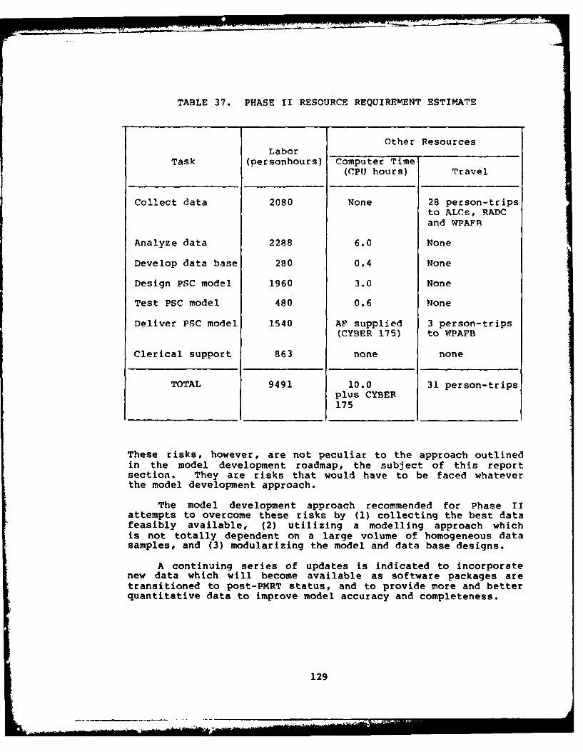
TABLE 37. PHASE II RESOURCE REQUIREMENT ESTIMATE
Other ResourcesLabor
Task (personhours) Computer Time(CPU hours) Travel
Collect data 2080 None 28 person-tripsto ALCs, RADCand WPAFR
Analyze data 2288 6.0 None
Develop data base 280 0.4 None
Design PSC model 1960 3.0 None
Test PSC model 480 0.6 None
Deliver PSC model 1540 AF supplied 3 person-trips(CYBER 175) to WPAFB
Clerical support 863 none none
TOTAL 9491 10.0 31 person-tripsplus CYBER175
These risks, however, are not peculiar to the approach outlinedin the model development roadmap, the subject of this reportsection. They are risks that would have to be faced whateverthe model development approach.
The model development approach recommended for Phase IIattempts to overcome these risks by (1) collecting the best datafeasibly available, (2) utilizing a modelling approach whichis not totally dependent on a large volume of homogeneous datasamples, and (3) modularizing the model and data base designs.
A continuing series of updates is indicated to incorporatenew data which will become available as software packages aretransitioned to post-PMRT status, and to provide more and betterquantitative data to improve model accuracy and completeness.
129

Data Risks
The data risks relate to the availability of requisite data,and whether the available data satisfies the attributes ofcomprehensiveness, completeness and representativeness, ispertinent, and is adequate in quantity and quality.
1) The data, while accurate, may not contain the requiredintelligence. The quantitative data may not be ofsufficient quantity and quality to determine meaningfulresults by unbiased analyses.
* Proper analysis techniques may not provide therelationships that are expected.
* Rigorous and correct statistical analysis techniquesmay show poor or insignificant correlations amongindependent and dependent variables.
* Root cause/effect relationships may not be thereexcept through qualitative (opinions, feelings,
etc.) means. (The effort then becomes a modelrepresentation of the modeller's biases andpre-conceived views.)
2) The data, while complete, may not be accurate. Forexample:
* Wrong manhours may have been recorded against thesoftware support tasks and subtasks.
* Significant labor may have been cross-recorded amongtasks, or cross-recorded with tasks unrelated tosoftware support.
* There may have been cross-recording or mis-recordingof other costs related to software support.
* How much of the data represents actuals versus how
much represents allocations?
3) The data may be too heavily qualitative. While somejudicious use of qualitative data is recognized to berequired, paucity of quantitative data may necessitatetoo great a dependence on the opinions (and otherbiases) of practitioners and the modeller to fill thequantitative data voids.
Approach Risks
The model design approach risks relate to constraintsimposed on model usage. The approach, while satisfying theminimum input/ease of use requirements, is also constrained bythem.
130

Software concepts/designs which are candidates for earlyprogram cost predicting must be reducible to a description interms of characteristics compatible with the PSC model inputrequirements, i.e., the minimum, easy input. If a candidatesoftware package type is significantly different from those uponwhich the model is based, it may not be readily represented bymodel-compatible input characteristics, and exercise by the modelmay be limited or impossible.
The ability to update the model based on new performancedata is a constraint imposed by the model design approach. Themodel will have been based on the precise set of data from thedata collection task. New performance data can be handled inone of several ways: add the new data to the existing data andredesign the model; design a new model based on the new data;or provide modularity in the model and data base designs toaccommodate modular add-ons/modifications. The PSC model designapproach outlined in this section provides for the latter methodof handling new performance data.
Model Usage Risks
Characteristics of software used as model inputs in earlyprogram cost studies may be changed significantly duringsubsequent phases of the program. The characteristics must bedefinable, specifiable as requirements, and enforceable for newsoftware programs. If input characteristics provided for costanalysis in early program trade studies are not controlled, andare changed when software design and development is implemented,predicted software support costs (from the PSC model) wouldalways be much different from resulting actual software supportrequirements and their costs. This would make the PSC modelappear to be "wrong" when, in reality, the conditions (inputcharacteristics) were changed. The model flexibility andsensitivity should handle some change, but not drastic changesin basic software package characteristics.
Model usage risks also relate to interpretation andapplication of results of studies which utilize the PSC model.No model is the perfect predictor in absolute terms. However,when conditions are held constant for comparing one softwarealternative with one or more other alternatives, relative valuesof the predictions can be excellent comparative evaluationtools. In other words, don't hang your hat on the absolutepredicted cost values, but put a great deal of stock in relativedifferences, when the predicting model is sound.
131

The PSC model that will have been designed in Phase IT willbe based on experience over the preceeding 4-5 years, temperedby current conceptual prognostications. The model will then,be applied to subsequent software programs. If the advances'in software technology during the period the model is intendedfor use are as rapid as they have been in the recent past, willthe model be current enough to be effective? What about thenew software technology advancements - unknown now, but boundto occur? Here, again, the modular model design approach comesinto play.
132
IX. CONCLUSIONS
Two primary conclusions are drawn from results of PhaseI of the PSCM study:
1) A new model directed at avionics software support cost
prediction is needed.
2) Development of such a model is feasible.
Other concLusions from the study are secondary in nature,expanding upon and supporting these two.
A new predictive software cost model should be developedto satisfy the Air Force requirement to be able to predictsoftware costs (especially software support costs) in planningthe development of advanced avionics systems.
* Existing software cost models do not adequately addressthe aspects of software support costs.
- Most models concentrate on estimating costs ofsoftware development and give little, if any,attention to costs of software support. As acorollary, the sophistication of treatment forsoftware development aspects far exceeds that givento software support aspects.
- Models do not generally reflect AFLC supportprocesses, and they do not account for a large portionof the support resources required.
* Good modelling technology exists which can be readilyapplied to software support estimating.
- Techniques used in the (primarily) softwaredevelopment cost prediction models may be applicablein addressing software support cost aspects.
* A lack of definitive historical data on softwareoperation and support and their associated costs hashampered support cost estimating and assessment of itscontribution to software life cycle costs.
* There is insufficient understanding of the factors thatdrive and otherwise affect software support costs.
- Most models consider manpower as the key driver to
the virtual exclusion of other important factors.
* Bases upon which most models are built are extremelylimited.
133
- Software program size, or the number of instructions,forms the basis for most software cost models. Other/additional pertinent software program characteristicsshould be identified, and additional estimatingrelationships developed for the software support costapplication.
* Distinct software packages being supported by AFLC arenumerous, and increasing at an ever increasing rate.
- Over 50,000 separate embedded computer system programsare currently c3timated to be in the Air Forceinventory, increasing at a rate of 6400 packages peryear.
It is feasible to develop a new predictive software costmodel which adequately addresses software support costestimations. While the amount of available quantitative datais marginal, its adequacy can be improved by making use ofvarious special studies and survey5 of key software engineersand managers; modelling technology is adequate; only the approachneed be established.
* Data from six sample software packages and from other
identified data sources indicate there is probablyadequate quantity and quality of data upon which to basethe desired model design.
- Some quantitative data on changes and manhours isreadily obtainable on the A-7D and F/FS-I1 aircraftOFPs. Data on the F-15 and F-16 will become availablein the future. Data on other packages and on EWsoftware may be obtainable by a manual search ofproject files. Other cost data and relationship data,such as the impact of V&V requirements on aircraftflight test requirements, will have to be obtainedby special studies and interviews of experiencedpractitioners in the field.
- Additional data will have to be collected to updatethat which has already been collected, and to fillinformation voids.
* Methods of collecting software support performance datadiffer among ALCs, with differing emphases that reflectprogram tailoring and size as well as accountingpractices.
- Software support within the ALCs is generally task
oriented.
* The new model should be developed, to the extentpossible, based on quantitative historical softwaresupport performance data, supplemented by qualitativeinformation from software practitioners.
134

* Six primary resource categories should be included in the
model design.
- personnel
- support equipment
- support software
- facilities
- data and documentation
- flight test
* Five primary support cost drivers determined in the Phase
I study should be included in the model design.
- change requirements, both frequency and size
- prime system software, including program size,architecture, and hardware constraints
- prime system hardware
- software support personnel, including experience,training and productivity
- test requirements for software changes
* The best modelling methodology of the alternativesevaluated is a modified bottom-up (element estimate)approach.
- The recommended approach best utilizes available data;it also provides ease-of-use by minimizing user inputrequirements.
- The modular feature of the approach provides updatingcapability for new data, and enables modifications(modular add-ons) to accommodate new requirements.
* The primary risk of the recommended methodology centersabout the availability of requisite historical data.The quality and quantity of available data may be lessthan expected.
135
X. OBSERVATIONS AND RECOMMENDATTONS
OBSERVATIONS
In conducting the field surveys during this study, severalobservations were made which are only partially or not directlyrelated to the purposes of this study. They are as follows:
1. An Air Force-wide software support data system analogousto the AFM 66-1 hardware maintenance data collection system hasnot yet been established, nor are there apparently any immediateplans to do so. Furthermore, it is difficult (if not impossible)to identify the effort related to software development in varioussystem acquisitions. This lack of consistent, uniform historicaldata imposes a severe handicap on the Air Force's ability tounderstand, compare and predict software support needs,capabilities and performance.
2. Operational flight programs for training simulatorshave to be written after the aircraft OFPs are completed. Thisnot only imposes an additional programming burden on the AirForce, but also exacts the undesirable side effect that trainingsimulators normally lag the operational aircraft by about oneblock change cycle.
3. Several persons expressed the desirability of MMEC (andother software organization) representatives from the variousALC's meeting together periodically to exchange information onvarious problems, proposed solutions, and possible approachesto technological and managerial improvements in the support ofavionics embedded software.
RFCOMMENDATIONS
The following recommendations are offer-d for Air Forceconsideration:
1. The Air Force Avionics Laboratory should pursueimplementation of the plan detailed herein for development ofa model to predict the support costs of avionics embeddedsoftware.
2. The Air Force Logistics Command should move to developand implement a system to collect data on the support of avionicsembedded software. As a related effort, the Air Force SystemsCommand should refine the Work Breakdown Structure to clearlydelineate, specify and control the software-related efforts onall new acquisitions.
137
i ECExDN pA, BLAwNOr nID

3. The Air Force should investigate the technicalfeasibility and economic desirability of designing aircrafttraining simulators so that they can utilize the same operationalflight programs as the operational aircraft.
4. The Air Force Logistics Command should sponsor periodicmeetings of representatives from all Air Force organizationsinvolved in designing cr supporting avionics embedded software,in order to facilitate understanding of common problems andenhance communication of possible solutions and technologicalimprovements.
I
138
PSCM BIBLIOGRAPHY
I. Regulations and Procedures
1. MM Operating Instruction 800-14, "AcquisitionManagement," Warner Robins ALC, Robins AFB, Georgia,15 November 1978
2. MMEC Operating Instruction 800-14, "Software ChangeProcessing Procedures for Operational Flight Programs,"2 June 1978
3. "F-ill Configuration Management Documentation Guidefor MMECP Software," Sacramento ALC, Sacramento, Ca.,14 December 1978
4. "F-ill Operational/Support Configuration ManagementProcedure for F/FB-lll Operational Software,"Sacramento ALC, Sacramento, Ca., 1978
5. Air Force Regulation 800-14, Vol I, "Management ofComputer Resources in Systems," 10 May 1974.
6. Air Force Regulation 800-14, Vol. II, "Acquisitionand Support Procedures for Computer Resources inSystems," 26 September 1975.
7. Department of Defense Directive 4100.35, "Developmentof Integrated Logistic Support for Systems/Equipments,"October 1, 1970.
8. Department of Defense Guide 4100.35-G, "IntegratedLogistic Support Planning Guide for DoD Systems andEquipments," October 15, 1968.
9. MIL-STD-483, "Military Standard ConfigurationManagement Practices for Systems, Equipment, Munitionsand Computer Programs," 31 December 1970.
10. MIL-STD-490, "Military Standard Specification
Practices," 30 October 1968.
11. Department of Defense Standard 7935.1-S, "Automated
Data System Documentation Standards," 13 September1977.
12. MMR Operating Instruction 800-01, "Software ChangeProcessing/Configuration Management for EW Systems,"(Draft) , 12 December 1979
13. MMEC Operating Instruction 65-2, "ConfigurationManagement for Avionics Integration SupportFacilities," (Draft)
139

14. MMR Operating Instruction 800-03, "System VerificationTest Procedures Using Simulation and Analysis TestSystems," (Draft), 12 December 1979
15. MMR Operating Instruction, "Software TestingGuidelines," (Draft), 12 December 1979
16. MIL-STD-1521A, "Technical Reviews and Audits forSystems, Equipment, and Computer Programs," DoD,1 June 1976
17. AFR 173-10, Volume I, "USAF Cost and Planning Factors,"6 February 1975, revised 2 May 1977
[I. AFWAL/AA and ALC Data and Reports
18. "Embedded Computer System Integrated Support Plan,"Vols. I,II & III Oklahoma City ALC, TinKer AFB,Oklahoma, January 1979
19. "Definition of An Approach to Establishment of an F-15Avionics Software Support Capability," AvionicsEngineering Directorate, Aeronautical Systems DivisionReport ASD-TR-74-30, Wright-Patterson AFB, Ohio, July1974
20. "Avionics Operational Flight Program Integrated SupportPlan," Warner Robins ALC, Robins AFB, Georcia, No.31073-6041-TU-00, January 1978
21. "Embedded Computer Resources," Engineering Livision,Directoratc of Material Management, Warner Robins AFB,Georgia, April 1978
22. "F-16 FCC OFP Independent Assessment. Final Report,"Simulation Technoloay Report STI-78-545, 14 July 1978
23. "F-16 Independent Assessment Fire Control ComputerOperational Flight Program Validation Plan andProcedures," Simulation Technology Report STI-78-545,September 30, 1978
24. Vendt, B. A., "Software Support For the F-16 AvionicComputers," Air Force Institute of Technology, ReportAD-A020-361, Wright Patterson AFB, Ohio, December 1975
25. "Air Force Computer Resources Inventory," ASD ComputeiCenter - CPIN Accession Listing (Sample Printout)
26. Heinger, K. L. and Parnas, D. L., "SoftwareRequirements for the A-7E Aircraft," Naval ResearchLaboratory NRL Memorandum Report 3876, November 1978
140
27. "Shopping List" ... a listing of hardware and softwarerequired for operational (maintenance) support of theA-7D Computer Laboratory, dated April 9, 1979
28. "Data Reduction Subroutine Analysis"... tabular summaryof A-7 OFP and support software routines identifyinglines of code, calls, branches, and variables andrelative time (for a programmer or systems engineer)to learn
29. "TM7503-291 on Revised Project Plan for Joint NRL-NWCAvionics Software Structuring Demonstration (W/A-7DOFP Maintenance History Milestones Chart)," 15 November1978
30. "A-7 OFP/Pave Penney Program Assembly Revision History,Program Change Flows, and Program Listings, Air Force2 Pave Penney Baseline AF2P-2," January 6, 1979
31. A-7 Change Control Methods Outline and Sample SourceChange Listing
32. A-7 Software Guideline, May 21, 1979. (Softwaredocumentation and coding techniques requirements)
33. "Operational Support Flight Manual," USAF Series, A-7D,No. T.O. lA-7D-lS-103, 7 May 1973
34. "A-7E TC-2/2A Software Tools Referen'ce Manual," NWCTechnical Memorandum 3595, NWC, China Lake, Ca.,September 1978
35. "A-7D OFP TC-2/2A Handbook Assembler," NWC TechnicalMemorandum 3597, NWC, China Lake, Ca., September 1978
36. "A-7D OFP TC-2/2A Assembly," NWC Technical Memoran'um3596, NWC, China Lake, CA., September 1978
37. F-15 Avionics Software Computer Resources IntegratedSupport Plan (CRISP), March 1978
38. WR-ALC Computer Resources (MMEC), Work Center Commentsand Time Standard Description (with MMEC Work FlowDiagrams)
39. WR-ALC F-15 Avionics Integrated Support FacilityPeynomic Simulator System Specification
40. Smithhisler, W. L., "F-15 SAR Radar Life Cycle CostAnalysis Report," Hughes Aircraft, IDC (orig.28-57-00), 2 November 1978
141

41. "F-ill Charter for the MMECP Steering Committee(listing printout)," Sacramento ALC, Sacramento, Ca.,1978
42. F-Ill OFP Change Summary (listings), 9-74 through 19-79
43. "Computer Update for F-Ill Aircraft," SM-ALC/MME,Briefing Charts, 18 November 1978 (Note: includes OFPchange analysis data, cost estimates, program sizingtrade-offs, including F-IIIA/E NAV-BOMB analysis basedon AFAL-TR-79-1043 cited in references 111.2, and IV.5)
44. "DOT File Listing (computer/MIS printout)," F-ll OFP
and Support Software Programs, Sacramento ALC,Sacramento, Ca., 1979
45. F-16 OFP Summary Project Analysis, F-16 BlockIMMA-D76-003, Period August 28, 1979 (change historylisting printout)
III Technical Reports and Papers
46. Cost Reporting Elements and Activity Cost Tradeoffsfor Defense System Software, General ResearchCorporation Report FSD-TR-77-262, May 1977
47. F-Ill A/E Digital BOMB-NAY System Software Analysis,Battelle-Columbus Laboratories Report (AFAL-TR-79-1043,January 1979
48. Herd, J. H., et. al., Software Cost Estimation Study,Doty Associates Report AD/A-042 264, June 1977
49. Software Cost Estimating Methodology, AFAL-TR-77-66,August 1977
50. "Quantitative Software Models," Software EngineeringResearch Review, SRR-I, Data and Analysis Center forSoftware, Rome Air Development Center, Griffiss AFB,N.Y., March 1979
51. Summary of Technical Progress, Investigation ofSoftware Models, RADC Report TR-79-188, Rome AirDevelopment Center, July 1979
52. Embedded Computer Resources, Engineering Division,Directorate of Materiel Management, Warner Robins ALC,Robins AFB, Georgia, April 1978
53. Devenny, Capt. T. J., An Exploratory Study of SoftwareCost Estimating at the Electronic Systems Division,Air Force Institute of Technology, Wright-PattersonAFB, Ohio, September 1976 (Masters Thesis)
142
54. "Quantitative Software Models,"Software EngineeringResearch Review,SRR-l, Data & Analysis Center forSoftware, March 1979
55. Bourdon, Captain G. A. and Captain J. A. Duquette,A Computerized Model for Estimating Software LifeCycle Costs (Model Concept), Comptroller, ElectronicsSystems Division, Hanscom Air Force Base,ESO-TR-77-253, Vol I, April 1978
56. Herd, J. H., et. al., Software Cost Estimation Study,Vol I, Doty Associates Inc., TR No. 151, Rockville,Md., AD/A-042264, June 1977
57. Highland, R. W., "Exploratory Study of Software SupportCosts," IDC Ref 281742/111, Hughes Aircraft Company,24 July 1979
58. James, Lt. T. G. Jr., Software Cost EstimatingMethodology,Air Force Avionics Laboratory,Wright-Patterson AFB, Ohio, AFAL-TR-77-66, August 1977
59. Junk, W. S., and J. A. McCall, Softwart CostEstimation and Evaluation Handbook, General Electric,29 August 1978
60. Clapp, J. A., A Review of Software Cost EstimationMethods, The MITRE Corporation, ESD-TR76-2 7 1, August976
61. Freiman, F. R., "PRICE Software Miodel - 6verview,"RCA PRICE Systems, Cherry Hill, N. J., November 1977
62. Stone, A. J., "1976 -.R&D Year-Fn Re-sort on SoftwareLife Cycle Cost Analysis," Hughes Aircraft Comp.any,i971
63. Schane, R. N., "Potential Effects of Standardizationon Avionics Software Life-Cycle Cost," 1979 NAECONProceedings, Logicon Report 7R-79-101, 29 June i979,pp. 558-567
64. Babiak, Captain N. J. and L. D. Parriott, Jr.,"Management of Embedded Computer Support kacilities,"Proceedings of (AIAA) Computers in AerospaceConference, Los Angeles, Ca., November 1977, pp286-296
65. Bridgman, M. S., F. Hitt, and T. R. Cork,"Assessment of Software Development and MaintenanceCosts Due to Retrofit .. Embedded AvionicsComputer," Proceedings of 2nd Computers in AerospaceConference, October 1-979, pp 17-22
143

66. Ferens, D. V., and R. L. Harris, "Avionics ComputerSoftware Operation and Support Cost Estimation,"Proceedings of the IEEE 1979 NAECON, Dayton, Ohio,15-17 May 1979
67. Norden, P. V., "Project Life Cycle Modeling," SoftwarePhenomenology - Working Papers of the Software LieCycle Management Workshop, Airle House, August 1977
68. Putnam, L. H., "A General Empirical Solution tothe Macro Software Sizing and Estimating Problem,"IEEE Transactions on Software Engineering, Vol SE-4,July 1978
69. Stone, Harold S., "Life Cycle Cost Analysis ofInstruction-Set Architecture Standardization forMilitary Computer Systems," Computer, April 1979,pp 35-47
70. Walston, C. E., and C. P. Felix, "A Method ofProgramming Measurement and Estimation," IBM SystemsJournal, Volume Sixteen, Number one, 1977, pp 54-75
71. Merrill, D. H., "Software Costing Models," IDC Ref.7555.31/24, Hughes Aircraft Company, 7 September 1979
72. Metrics of Software Quality, McDonnell DouglasAstronautics Company Report MDC-G7517, July 1978
73. Norden, P. V., "Useful Tools for Project Management,"Management of Production, M. K. Starr (Ed.), PenguinBooks, 1970
74. Modular Life Cycle Cost Model for Advanced AircraftSystems Phase II, Vol I, Cost Methodology Developmentand Application, AFFDL-TR-78-40, Grumman AerospaceCorporation, Bethpage, New York, April 1978
75. Irvine, A. and M. Mckenzie, Evaluation of the DSNSoftware Methodology, DSN Progress Report 42-48,September and October 1978
76. Dalkey, N. C., "The Delphi Method: An ExperimentalStudy of Group Opinion," the Rand Corporation,RM-5888-PR; Santa Monica, California, 1969.
77. DeRoze, B. C., Defense System Software ManagementPlan, Report AD/A-022 558, National TechnicalInf-ormation Service, Springfield, Virginia, 1976.
78. DeRoze, B. C. and Nyman, T. H., "The Software LifeCycle," SIGNAL, Nov/Dec. 1977
144

79. DoD Weapon Systems Software Management Study, TheJohns Hopkins University Applied Physics Laboratory,Maryland, 1975.
80. Findings and Recommendations of the Joint LogisticsCommanders Software Reliability Work Group (SRWGReport) (2 volumes) , Air Force Systems Command,Andrews Air Force Base, District of Columbia, 1975
81. McCall, J. L., et. al., Factors in Software Quality,RADC-TR-77-369, Rome Air Development Center, GriffissAir Force Base, New York, 1977
82. Myers, G. J., Software Reliability Principles andPractices, New York: John Wiley and Sons, 1976
83. Ortega, L. H., "Documentation Standards Final Report,"Vol VII, Structured Programming Series, ReportRADC-TR-74-300, Rome Air Development Center, GriffissAir Force Base, New York, 1974
84. Smith, R. L., "Estimating Software Project ResourceRequirements," Vol. XI, Structured ProgrammingSeries, Report RADC-TR-74-300, Rome Air DevelopmentCenter, Griffiss Air Force Base, NeW York, 1975
85. Patterson, A. F., and E. M. Long, "The F-Ill OFPDynamic Simulation System," Proceedings of the IEEE1976 NAECON, Dayton, Ohio, 18-20 May 1976.
86. Freedman, R. J., "Organic Support of the A-7E AirbornComputer System," Proceedings of the AeronauticalSystems Software Workshop, National TechnicalInformation Service Report AD/A-004-547, July 1974,pp. 261-286
87. Teichgraeben, R. D., and D. M. DeMoss, "Real TimeSimulation as a Tool for F-16 Operational FlightProgram Development and Testing," Proceedings of theAIAA 2nd Digital Avionics Systems Conference,November, 1977
88. Anderson, P. G., "Redundancy Techniques for SoftwareQuality," 1978 Proceedings Annual Reliability andMaintainability Symposium, Los Angeles, Ca., 17-19January 1978
89. Belady, L. A., "Software Complexity," SoftwarePhenomenology - Working Papers of the Software LifeCycle Management Workshop, Airle House, August 1977
145

90. Belady, L. A., "Measures and Empirical Studies,"Working Papers of the Second Software Life CycleManagement Workshop, IEEE, Atlanta, Georgia, August21-22, 1978
91. Boehm, B. W., "Quantitative Evaluation of SoftwareQuality," Software Phenomenology-Working Papers of theSoftware Life Cycle Management Workshop, Airle House,August 1977
92. Boehm, B. W., "Software and Its Impact: A QuantitativeAssessment," Datamation, May 1973, pp 48-59
93. Brooks, F. P. Jr., "The Mythical Man-Month,"DATAMATON, December 1974, pp 45-52
94. Curtis, B., et. al., "Some Distinctions Between thePsychological and Computational Complexity ofSoftware," Working Papers of the Second Software LifeCycle Management Workshop, IEEE, August 1978
95. Cave, W. C., and A. B. Salisbury, "Controlling theSoftware Life Cycle - The Project Management Task,"IEEE Transactions on Software Engineering, VolumeSE-4, Number 4, July 1978
96. Ferrell, J., "Logical Planning for Automatic TestEquipment Software Requirements," Computers inAerospace Conference, Los Angeles, Ca., November 1977pp 260-267
97. Gardiner, P. C., "Multi-Attribute Utility Measure forLogistics Decision Making," Parts I and II, SPECTRUM,Winter 1978 and Summer 1979
98. Goodenough, J. B., and S. L. Gerhart, "Toward a Theoryof Test Data Selection," IEEE Transaction on SoftwareEngineering, Vol SE-I, No 2, June 1975
99. Griffith, V. G., "Can HOL Use In Avionics Pay forItself?," Aeronautical Systems Software Workshop,July 1974
100. Henry, R. C., "Notes on Software Reliability andQuality," Software Phenomenology - Working Papers ofthe Software Life Cycle Management Workshop, AirleHome, August 1977
101. "Control Data Cyber 170 Series," 70C-263-12A Computer,Datapro Research Corporation, Delran, N. J., June 1977,revised May 1978
102. "JPL Improves Software Development Process," COMPUTERIEEE, February 1978, pp 22-25
146

103. Kline, M. B., "Software and Hardware R & M: WhatAre the Differences?," 1980 Proceedings AnnualReliability and Maintainability Symposium, pp 179-185
104. Manley, J. H., "Software Life Cycle Management:Dynamics Theory", Working Papers of the SecondSoftware Life Cycle Management Workshop, Atlanta,Georgia, August 21-22, 1978
105. McCabe, T. J., "Software Complexity Measurement,"Working Papers of the Second Software Life CycleManagement Workship, IEEE, August 1978
106. Miller, C. R., "Software Maintenance and Life CycleManagement," Software Phenomenology - Working Papersof the Software Life Cycle Management Workship, AirleHouse, 21-23 August 1977
107. Myers, W. (Contributing Editor), "The Need for SoftwareEngineering," Computer, IEEE, February 1978
108. Peercy, D. E., "A Software Maintainability EvolutionMethodology," AIAA 2nd Computers in AerospaceConference, October 197J, pp 315-325
109. Rubey, R. J., J. A. Dana, and P. W. Biche,"Quantitative Aspects of Software Validation," IEEETransactions on Software Engineering, Vol SE-I, No2, June 1975
110. De Roze, B. C., "The Software Life Cycle - A Managementand Technology Challenge in the Department of Defense,"IEEE, Transactions on Software Engineering, Vol SE-4,No 4, July 1978, pp 309-317
111. Snyders, J., "Slashing Software Maintenance Costs,"Computer Decisions, July 1979, Pp 44-50
112. Tansworth, R. C., "The Workbreakdown Structure inSoftware Project Management," Working Papers of theSecond Software Life Cycle Management Workshop, IEEE,August 1978
113. Walters, G. F., and J. A. McCall, "The Development ofMetrics for Software R & M," Proceedings of the 1978Annual Reliability and Maintainability Symposium,Los Angeles, California, 17-19 January 1978
114. Wolverton, R. W., "Software Life Cycle Management -Dynamics Practice," Working Papers of the SecondSoftware Life Cycle Management Workshop, IEEE,Atlanta, Georgia, August 21-22, 1978
147
115. Boehm, B. W., "The High Cost of Software," Proceedingsof a Symposium on the High Cost of Software, Monterey,California, 1973 (published by Stanford ResearchInstitute, Menlo Park, California)
116. Boehm, B. W., et. al., Characteristics of SoftwareQuality, TRW Software Series TRW-SS-73-09, December1973
117. Drezner, S. M., et. al., "The Computer ResourcesManagement Study," The Rand Corporation R-1855/1-PR.,Santa Monica, California, 1976
118. Dunn, R. H. and Ullman, R. S., "A Workable SoftwareQuality/Reliability Plan," Proceedings of the 1978Annual Reliability and Maintainability Symposium,Los Angeles, Ca., 17-19 January 1978
119. Howley, P. P., "Software Quality Assurance for ReliableSoftware," Proceedings of the 1978 Annual Reliabilityand Maintainability Symposium, Los Angeles, Ca., 17-19J-anuary 1978
120. "Implications of Using Modular Programmins," GuideNr. 1, John Hoskyns and Company, Ltd., Hoskyns SystemsResearch, Inc., 600 Third Avenue, New York, New York,1973
121. Lindhorst, W. M., "Scheduled Maintenance ofApplications Software," Datamation, May 1973
122. McCarthy, R., "Applying the Technique of ConfigurationManagement to Software," Defense Management Journal,October 1975
123. Mooney, J. W., "Organized Program Maintenance,"Maintenance," Datamation, February 1975
124. Munson, J. B., "Designing for Software Maintainability- A Major Concern for Life Cycle Costing," 1978Conference on Design to Cost/Life Cycle Cost, Stateof the Art Seminars, Los Angeles, California
125. Proceedings of a Symposium on the High CosL ofSoftware, Monterey, California, 1973 (published byStanford Research Institute, Menlo Park, California)
126. Shooman, M. L. and Bolskey, M. I., "Software Errors:Types, Distribution, Test and Correction Times,"International Conference on Reliable Software, 1975
148

1/7. Sukert, A. N., "An Investigation of SoftwareReliability Models," Proceedings of the 1977 AnnualReliability and Maintainability Symposium, TheInstitute of Electrical and Electronic Engineers, Inc
128. Swanson, E. B., "The Dimensions of Maintenance,"Proceedings of the Second International Conference
on Software Engineering, San Francisco, 1976
129. Trainor, W. L., "Software - From Satan to Saviour,"
USAF Avionics Laboratory, Wright-Patterson Air Force
Base, Ohio; paper presented at National AerospaceElectronics Conference, 1973
130. Uolverton, R. W., "The Cost of Developing Large-ScaleSoftware," IEEE Transactions on Computers, Vol C-23,
Nr. 6, June 1974
131. Wulf, W. A., "Programming Methodology," Proceedings
of a Symposium on the High Cost of Software, Monterey,California 1973
132. Parnas, D. L., "Designing Software for Ease ofExtension and Contraction," IEEE Transactions onSoftware Engineering, Vol. SE-5, No. 2, March 1979
133. Mills, Capt. B. S., "Simplified Procedures forPerforming Life Cycle Cost Analyses," Proceedings of
the IEEE 1979 NAECON, Dayton, Ohio, 15-17 May 1979
134. Patterson, A. E., "Operational Flight Programs: Change
and Control," Conference Proceedings on Managing ofWeapon Systems Software, USAF University, MaxwellAFB, ALA, May 1976.
135. Patterson, A.E., and Capt. R. G. Algire, "An Approachto Modern Avionics Integration Support," Procedingsof the IEEE 1976 NAECON, Dayton, Ohio, 18-20 May 1976.
149
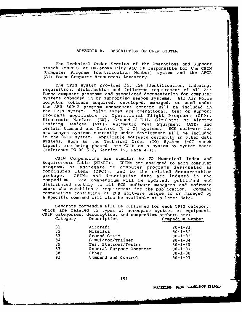
APPENDIX A. DESCRIPTION OF CPIN SYSTEM
The Technical Order Section of the Operations and SupportBranch (MMEDU) at Oklahoma City ALC is responsible for the CPIN(Computer Program Identification Number) system and the AFCR(Air Force Computer Resources) inventory.
The CPIN system provides for the identification, indexing,requisition, distribution and follow-on requirement of all AirForce computer programs and associated documentation for computersystems embedded in or supporting weapon systems. All Air Forcecomputer software acquired, developed, managed, or used underthe AFR 800-2 program management concept will be included inthe CPIN system. Major types are operational, test or supportprograms applicable to Operational Flight Programs (OFP),Electronic Warfare (EW), Ground C-E-M, Simulator or AircrewTraining Devices (ATD), Automatic Test Equipment (ATE) andcertain Command and Control (C & C) systems. ECS software fornew weapon systems currently under development will be includedin the CPIN system. Applicable software currently in other datasystems, such as the Technical Order (TO) System (-CT checktapes), are being phased into CPIN on a system by system basis(reference TO 00-5-2, Section IV, Para 4-1).
CPIN Compendiums are similar to TO Numerical Index andRequirements Table (NI&RT). CPINs are assigned to each computerprogram, or aggregate of computer programs designated asconfigured items (CPCI), anC to the related documentationpackage. CPINs and descriptive data are indexed in thecompedium. The compendium will be updated, published anddistribited monthly to all ECS software managers and softwareusers who establish a requirement for the publication. Commandcompendiums consisting of ECS software unique to or managed bya specific command will also be available at a later date.
Separate compendia will be published for each CPIN category,which are related to types of aerospace systems or equipment.CPIN categories, description, and compendium numbers are:
Category Description Compedium Number
81 Aircraft 80-1-8182 Missiles 80-1-8283 Ground C-h-M 80-1-8384 Simulator/Trainer 80-1-8485 Test Stations/Tester 80-1-8587 General Purpose Computer 80-1-8788 Other 80-1-8891 Command and Control 80-1-91
151
9WCED1NO PAal &iAhK-OT FILMO
CPIN 80-1-81
USAF
COMPUTER PROGRAM IDENTIFICATION NUMBER SYSTEM
COMPENDIUM
OF
AIRCRAFT
EMBEDDED COMPUTER SYSTEM SOFTWARE
FIRST EDITION
PUBLISHED UNDER AUTHORITY OF THE SECRETARY OF THE AIR FORCE
1 JUNE 1979
152
4

CPIN 80-1-81
FABLE OF CONTENTS
Page
INTRODUCTION ................................................................................ i
PREFACE.......... ........................................................................ ii
TABLE OF CONTENTS..............................................................................jjjI
PART I - ACTIVE COMPUTER PROGRAM IDENTIFICATION NUMBERS (CPIN) ...........................
A OPERATIONAL FLIGHT PROGRAMS ............................................... 1
B ELECTRONIC WARF ,IE ........................................................ 14
C COMMUNICATIONS ............................................................ 32
D DATA PROCESSING OR DISPLAY ................................................ 34
E ENGINES ................................................................... 40
F FLIGHT CONTROLS ........................................................... 46
G GUIDANCE .................................................................. 47
H NAVIGATION ................................................................ 49
J WEAPONS DELIVERY......................................... ... 50
K FIRE CONTROL ............................... . . .. 52
L MISSILE LAUNCH........................... 54...............................
M METEOROLOGY ............................................................... 56
N ENVIRONMENTAL AND EGRESS .................................................. 58
P PHOTOGRAPHY ............................................................... 60
Q ELECTRONIC AND ELECTRICAL ................................................. 62
R ARMAMENT AND MUNITIONS .................................................... 64
S FUEL ...................................................................... 66
T MULTIPLE MAJOR FUNCTIONS ....................................... .......... 68
U HYDRAULIC, PNEUMATIC, PNEUDRAULIC, AND VACUUM ............................. 70
V GENEPAL PURPOSE OR SUPPORTIVE ............................................. 72
Z OTHER ..................................................................... 74
153

CPIN 80-1-81
PART I - ACTIVE
COMPUTER PROGRAM IDENTIFICATION NUMBERS (CPIN)
CATEGORY 81 - AIRCRAFT
A OPERATIONAL FLIGHT
ARNI01 - AN/ARN-I01 - NAVIGATION SET, LORAN
Off 81A-ARN101-FOO1-OOA REV 11; 12 FEB 79 (U) ABD 00
OFP for NC of F-4E DMAS ARN-101, Provides navigation usingINS/LORAN inputs, calculates various weapons delivery modes, 1punched mylar tape, NO. PROG/CPC 1, LANGUAGE Assembly, OPERATORMANUAL TO Not prepared, SUP COM IBM 360/65, SUP PROG Assembler,Linkage Editor, Simulator, Translator, Nag Tape UtilityAPPL SYS: F-4E.APPL SUBSYS: AN/ARN-l01.
*m 81A-ARNO1-FOO1-OOD REV 11, 12 FEB 79 (U) ABD 00
DOCUMENTATION PACKAGE CONTAINS: Computer Program DevelopmentSpec for F-4E NC CB1001-O, Computer Program Product Spec forF-4E NC DD1001-, Programmers Notebook, Version DescriptionDocument, Configuration Index, Change Status Report, CorputerProgram Manual SE, Cat I Test Plan/Procedures SE, Cat I TestReport SE, Test Requirements Document, Spec Change Notice
81A-ARN1O1-F002-OOA REV 3, 2 FEB 79 (U) D 00
OFP for NC or RF-4C DMAS ARN-I01, Provides navigation usingINS/LORAN inputs, performs reconnaissance functions, 1 punchedmylar tape, NO. PROG/CPC 1, LANGUAGE kssembly, OPERATOR MANUALTO Not prepared, SUP COMP IBM 360/65, SUP PROG Assembler,Linkage Editor, Simulator, Translator, Mag Tape UtilityAPPL SYS: RF-4C.APPL SUBSYS: AN/ARN-01.
81A-ARN1O1-FO02-OOD REV 3, 2 FEB 79 (U) D 00
DOCUMENTATION PACKAGE CONTAINS: Computer Program DevelopmentSpec for RF-4C NC CB1001-O0, Computer Program Product Spec forRF-4C NC CC1001-00, Programmers Notebook, Version DescriptionDocument, Configuration Index, Change Status Report, ComputerProgram Manual SE, Cat I Test Plans/Procedures SE, Cat I TestReport SE, Test Requirements Document, Spec Change Notice
ASN91 - AN/ASN-91(V) - COMPUTER SET, TACTICAL
' 81A-ASN91-UOO1-OOA (U) B OCControl, EQUIP/UUT ID 216-01940-1, 6870000-11, 6870200-8, TCS,Memory diagnostics test, signal diagnostics, I/O diagnosticsrepair verification test, I punched tape, NO. PROG/CPC 1,LANGUAGE TC-2 Assembler, CTL COMP/TEST STA AN/ASM-403(V)l IBM,OPERATOR MANUAL TO 5N5-13-13-8-1, OFFLINEAPPL SYS: A-7D.APPL SUBSYS: AN/ASN-91(V).
B ELECTRONIC WARFARE
A(MX6770A) - MX-6770A/A - INTERFERENCE BLANKER
aa 81B-A(MX6770A)-UOO1-OOA REV 6, 4 FEB 79 (U) D WR
Checkout Interference Blanker, EQUIP/UUT ID 1E4000G3Interference Blanker, Test interference blanker P/N 1E4000G3 onGPATS, 1 mylar tape, NO. PROG/CPC 1, LANGUAGE Hexadecimal, CTLCOMP/TEST STA GSM204-V6 GPATS, UUT INTERFACE TEST ADAPTER7234476, OPERATOR MANUAL TO 51P7-2-2-8-3, OFFLINEAPPL SYS: F-1lIA, F-111E.APPL SUBSYS: MX-670OA/A.
2
154

CPIN 80-1-81
CATEGORY 81 -AIRCRAFT
PART II - CANCELLED SOFTWARE
81J-ASB9A( ASB16)-UOOI-OOA 81M-PNN16-U009-OOA81J-ASB9A(ASB16)-UOO1-OOD 81M-PNN16-U009-OOD81K-ASG19-UOO1-OOA 81Q-VBC(APN16)-T003-OOA8 1K-ASG19-UOO1-OOD 81Q-VBC(APN16)-T003-OOD81K-MA 1/ASQ25FDT-TOOI-OOA8 1L-GSM2&4-UO26-OOA
PART III - RESCINDED SOFTWARE
81J-ASB-4A(ASB9A)-UOOI-OOA81 J-ASB-I4A( ASB9A)-UO01-OOD81K-ASG24-UOO0l-OOA81 K-ASG24-UO04-OOA
PART IV -REIDENTIFIED CPINS
ORIGINAL CPIN NEW CPIN
81J-ASB4A(ASB9A)-S022-OOA 81M-ASB'4A(AS89A)-S002-OOA
81J-ASB'4A(ASB9A)-S022-OOD 81M-ASB4A(ASB9A)-SO02-OOD
3
155

CPIN/AFCRI DATA AND CONTROL RECORD - PART I
1. TO OC-ALC/'MMEDU 2. CON1TROLLING ALC"MMEC .3 F-6 REQUESTING AGENCY
TINKER AFB, OK 73145 ___CONTACT NAME'ADDRESS- -- CONTACT NAME & ADDRESS
(-THROUH CHANNELS___-- __-
4SECURITY' CLASSIFICATION -- __________
L:PcI - _ TITLE
5 DAIL PREPARED PHONE- -- PHONE_____________ __
MMEC CONTROL NO., AGENCY CONTROL NO.
t5iI10' TYP E AC TI ON LCI RCLE ONE', Z-OTHER (EXPLAIN IN REMARKS) 7. 040 TYPE SOFTWARE
A -NEW CL PC I F --NEW CPCI VER K-NEW CIPCI REV 0-ALID DATA DF -OPERATIONALI
R--NEW DOC G-NEW DOC VIR E-NEW DOC REV T-DELETE DATA '7 S SUPPORT
0-NEW CPCI/DOC H--NEW CPCI. DOC VER M -NEW CPCI'DOC REV V-REPLACE DATA T1-TEST
E --CANCEL J -RESCIND P-REINSTATE W-INOUIRY (AFCR I)7 U -UUT
8CURRENT NUMBERS REV 9. NEW NUMBERS ASSIGNEDRE
c PC I-- -- DOC --
U) 'LI I TO USER MANUAL
It. DOC 0' 0 PIN NUMBER -- -' REV. 2 1- -
.l10 IOET - r T O FUNCTION
3~~~~2 24 4S2 27 280At'213 1-tj~T~ 1 13 030SOFTWARE
GROUP
--------- MANAGER CODES SYMBOLS
0R o COMMANDCOOL xJ P1RIME I- -- V-.-
AI SMV, ACMMEC COD ROUTING ALO 1 M PE REEE
S '0 17 3R 19 40141 '42143'44'45'4R 47 AR149 'ST S1 52 53 54:55,561571 5R159 6c 61 R 263 64 5 66 15768 0
,V 7 72 3 4 5 6 7 'R /
j 4, N !I A H r
S 5555 IF. ISS .0 NO CPCS6 DATE CPCI COST LEVEE RESEPVED
P T0 i1 - -- A.~ .>-----
IJ C~ lC. PROGRAM_,T lILF E-
P 046
IS. CODE, RQUIPMENTIUT IDENTIFICATION
IR7-
II COOL'C' -RGRA- DESCRIP TON
FOT
P, 0
211. COO TJ 5 1 P L[It MEP*- - - - - -ROG L ANCU AGE
I' 6sto37 38 14 .4 At 4254 1 44 A- 46 47 44 49 SOS '52 ' S5-5 b 97 50! 59'6 1 :L 62 63 64'S 6667 8 69 707 72 7 4, -4 5 - 46 4
21. COL CON RSDu CO-A L. RE I LSr STA noN IDENTIC-ICATION
IS I r'
22. C 1* .. ~ --
kF "t, 1 r C L A - U P 0 I U S E S M N U A -
A FLC 505 PI818189 EDITION IS OBSOLETE 156

23. COi. ON-OFF23 CODE , LINE UPPORr rMPUTER DENT FICATI;ON
3 : 1- 7 - , w ,1 48'40' 5 A-51,51- i 5-4-- -'31---5! 6 9 .- - 701 71 21 "731 74 75 767 77 17- 79 -
320 dlI: , I T--4 _ - - - -
T7__
24. CODE SUPPORT PROGRAMS REQUIREDP 1 :6 I Ii / L ! + ___ _ _ _ _ _ _ .. 2 _ _ . .+
2 CD SPECIAL NOTES
26. ALL APPLICABLE SYSTEMS
-I-- -I-- L--- - -_____-- __ _ I
27. cooE ALL APPLICABLE SUBSYSTEMS
p~ 2-
1P 2 9' '
28. CODE DESCRIPION OF MEDIA UNITS'3.3!3 94041243 44 45 63474S 49 05 215 451 6 5 66 61' ; 7 Ed 69 70'7 1 72 7 3 ;74 75 76 177 70 79 30
P 3 12 1 I .*d- I I , ,ttV
29. 00ooE DOC UM ENTATION PACKAGE
R 0- 51 T ; ; I I
u lIl d f I /li -,+i l I _
3D. COONTETL COMPUTER
OPERA TING SYSTEM OALTr ESIGNATION DPINSTI. AOPE PLN
__ _ __ _ _ __ _ _ __ _ _ __ _ _ _.__ __ _ _ __ U .E____ _ _
ill~l, M I 3 11 IlNATIONAL STOCK NUMBER iNSNI MEMORY SIZE
31. CONTINUED DATA YES- NO OF PAGES
32. OC-ALC/MMEDU ACTION
Z NUMBERING ACTION
COMPLETED I RETURNED FOR
OC-ALC/MMEDU CONTACT A AE
157

CPIN/AFCRI DATA AND CONTR~OL RECORD - PART It
-AEPRIME ALCMMEC MMWI ('It NO NUMBER 0f PROGRAMS Al F S>O0N N iIMIfH
-OF - - 1 0
A - .IlRM!T ONE FORM FOR E ACH CPCi COMPUTER PRCK;RAM
COMPUTER PROIURAM
TI TIE
ACRONYM LOCAL I.0. N UM BER E NTRY -DA TE
1'3 ;0~ 1 40: .10J
STATUS VERSION REVISION VALIDATION GATE
I' 70 :O 1 8,0 : 190.
CONTRACTOR
NAME
21 3 1
NUMBER CONTRACT NUMBER
ABSTRACT
3 0
---- --. 1-4 -- i-- - 4
AFLC OwnE 506 P*tvious rIomo iso ........ 158

CPIN DATA (CONTINUED)
R
Is 30. 38 39 0 4 4
4 4 5 14 47140 43 01 51 5233 4 515 7 13al8 5990041?1 021630404 67 0ll 69 70 7 2 3 1701777 176079 0
:!
I-7--i _ ,, ,
35 3- 50! 5 52 s 54 55 56 5 5 9- -6 at Itl7a 3"4 Is 17 '- '
2--
159
II

I
APPENDIX B. TYPICAL POSITION DESCRIPTION OF AISFPERSONNEL DEVELOPING AND INTEGRATINGSOFTWARE CHANGES
Below is the official position description for a GS-12Electronic Engineer (Computer Systems). This descriptionoutlines the basic requirements of the work to be done, whetherperformed by Civil Service or contractor personnel.
I. INTRODUCTION
Incumbent of this position serves as an Avionics SystemEngineer responsible for accomplishing software and systemsengineering projects/tasks for avionics embedded computersystems, their resident Operational Flight Program (OFPs) andtheir support systems for assigned prime aircraft systems.
II. DUTIES AND RESPONSIBILITIES
1. Develops, coordinates and carries through to completionblocks of work of large scope containing many phases of whichtwo or more phases each contain several complex features. Plansand conducts research, development, or other work for whichprecedent data, criteria, methods or techniques are significantlyinadequate, are controversial, or contain critical gaps.Develops or originates completely new features, in additon toimproving, extending, or validating currently known precedents,data methods or techniques. In accomplishing the above,incumbent is responsible for the development of modificationsand changes to complex aircraft digital avionics systems, theirOperational Flight Program (OFPs), and laboratory support systems(e.g., Avionics Integration Support Facility (AISF) software.In addition, incumbent is responsible for the investigation,analys4 s, evaluation and reporting on avionics systemperformance, problems and new requirements.
2. Develops and carries through to completion complexchanges to the OFPs. Uses the AISF to analyze and evaluate OFPrequirements in order to develop optimum implementation.Investigates potential solutions to system problems/changerequirements considering tradeoff analyses involvingimplementation costs, algorithm developments, timingrequirements, memory size, hardware/software integrationrequirements, support equipment, personnel capabilities andlimitations, data package development and overall magnitude ofthe effort; and translates these change requirements intoengineering specifications and tasks. Designs the changemechanization and integration; develops the programming code;and debugs, tests and documents the results. At all timesassures aircraft system integrity and compatibility; and meetsresource allocations, performance criteria, cost and schedule.
161
- 1P-40

3. Establishes formal test requirements for OFPs; developsand implements test plans; conducts detailed tests using thefull capabilities of the AISF and instrumented flight testaircraft; and analyzes, evaluates and reports test results.
4. Serves as project engineer for the design anddevelopment of changes and modifications to the AISFhardware/software resources and o a n r se
Provides system engineering support and assures compatibilitywith the aircraft avionics, digital computer complexes and OFPs.Establishes change requirements directly with the AISF andavionics support systems users. Prepares change specifications,and plans and schedules the complete development andimplementation.
5. Conducts studies and evaluations of systems inacquisition and determines support requirements. Performsstudies, prepares Computer Resources Integrated Support Plans(CRISPs) and participates as a member of Computer ResourcesWorking Groups (CRWGs).
6. Prepares contractual engineering proposals andassociated specifications and work orders.
7. Monitors and maintains close liaison between contractorand Air Force activities associated with the engineering supportof digital avionics, embedded computer systems and OFPs forprime aircraft systems.
8. Reviews, evaluates and advises on thc effccJv'3rsotechnical adequacy and suitability of work and proposals otothers related to digital avionics and OFP support. Evaluatesmore complex vendor proposed modifications for requirements,feasibility, completeness, accuracy, cost, and operational andlogistics impact.
9. Consults, coordinates and attends conferences with otherservice activities and higher headquarters on matters nortaininqto avionics OFP development and support. Makes recommendationsto higher authority for changes to policies and practices, nasedon knowledge, experience, engineering studies, obseivations,and reports received from service activities, and defends ALCfindings and recommendations. Travels to contractor or othergovernment facilities to review engineering data and renderopinions and decisions which are normally unreviewed; maintainsliaison with other government activitps and contractors in orderto exchange engineering data and to maintain a cutrenz knowledgeof the state-of-the-art.
162
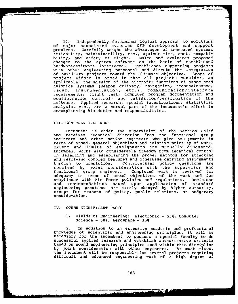
10. Independently determines logical approach to solutionsof major associated avionics OFP development and supportproblems. Carefully weighs the advantages of increased systemsreliability, maintainability, etc., against time, cost, compati-bility, and safety of flight. Makes and evaluates proposedchanges to the system software on the basis of establishedhardware/software interfaces. Establishes supporting projectswith other engineering personnel and directs the integrationof auxiliary projects toward the ultimate objective. Scope of
project effort is broad in that all projects consider, asapplicable: the mission of the aircraft; functions of associatedavionics systems (weapon delivery, navigation, reconnaissance,radar, instrumentation, etc.); communication/interfacerequirements; flight test; computer program documentation andconfiguration control; and validation/verification of thesoftware. Applied research, special investigations, statisticalanalysis, etc., are a normal part of the incumbent's effort inaccomplishing his duties and responsibilities.
III. CONTROLS OVER WORK
Incumbent is under the supervision of the Section Chiefand receives technical direction from the functional groupengineers and other senior engineers who give assignments interms of broad, general objectives and relative priority of work.Extent and limits of assignments are mutually discussed.Incumbent works with considerable freedom from technical controlin selecting and establishing the proper methods for attackingand resolving complex features and otherwise carrying assignmentsthrough to completion. Controversial policy questions areresolved by joint consideration with the supervisor andfunctional group engineer. Completed work is reviewed foradequacy in terms of broad objectives of the work and forcompliance with Air Force policies and regulations. Decisionsand recommendations based upon application of standardengineering practices are rarely changed by higher authority,except for reasons of policy, public relations, or budgetaryconsideration.
IV. OTHER SIGNIFICANT FACTS
1. Fields of Engineering: Electronic - 55%, ComputerScience - 30%, Aerospace - 15%
2. In addition to an extensive academic and professionalknowledge of scientific and engineering principles, it will benecessary for the incumbent to possess a special faculty to dosuccessful applied research and establish authoritative criteriabased on sound engineering principles used within this disciplineby joint consideration with other engineers. At most times,the incumbent will be responsible. for several projects requiringdifficult and advanced engineering work of a high degree of
163

originality, therefore incumbent must have a thorough anddetailed knowledge of: avionics digital systems, (e.g., inertialnavigation systems, fire control radars, stores managementsystems; digital controls and displays, etc.); aircraft embeddedcomputer systems; real-time operational flight software;laboratory support systems to include real-time simulationsystems, host computer systems and avionics system hot mock-ups;software configuration management; software documentation; OFPtesting, evaluation, verification and validation; and aircraftperformance and operation, specifically in the areas ofnavigation and weapon delivery. Must be experienced andknowledgeable in real-time programming, mathematical modeling,computer architecture and programming languages.
3. Incumbent must possess a high degree of professionaljudgment, skill, initiative, planning and leadership ability.Also must possess ability to maintain effective personal workrelationships at all levels and to justify and sell his ownprofessional viewpoints in conferences, engineering reviews andwith fairly large groups wherein conflicting points of view arerepresented. Requires an intimate knowledge of functions,organizational structure, jurisdictional responsibilites, etc.,of USAF and elements thereof.
4. The incumbent of this position must be capable andwilling to perform TDY travel in accordance with the Joint TravelRegulation.
5. Supports and takes affirmative actions in furtheranceof Equal Employment Opportunity in all aspects of personnElactions, with special emphasis on Upward Mobility and otherspecial programs.
6. Position requires a security clearance of Secret.
7. Performs other related duties as required.
8. Subject to call during off-duty hours.
9. All personnel will share in the responsibility for isound industrial safety program. Incumbent is required to complywith all applicable safety directives. Unsafe conditions areto be promptly reported to the immediate supervisor.
164

LIST OF ACRONYMS
AFB Air Force Base
AFCRI Air Force Computer Resources Inventory
AFIT Air Force Institute cf Technology, Wright-Patterson AFB, Ohio
AFLC Air Force Logistics Command
AFWAL/AA The Avionics Laboratory of the Air Force Wright Aeronautical Laboratories
ATSF Avionics Integration Support Facility
ALC Xir Logistics Center
ATD Aircrew Training Device
ATE Automatic Test Equipment
C3 Communications, Command & Control
CDR Critical Design Review
CE Communication Electronics
Ci Configured Item
CPCI Computer Program Configuration Item
CPCP Computer Program Change Proposal
CPCSB Computer Program Configuration Sub-Board
(CIN Computer Program Identification Number
CRISP Computer Resources Integrated Support Plan
r/.mm Director of Material Management
DSARC Defense Systems Acquisition Review Council
ECCM Electronic Counter Counter Measures
ECP Engineering Change Proposal
ECS Embedded Computer System
165

LIST OF ACRONYMS
EPROM Erasable Programmable Read Only Memory
EW Electronic Warfare
H/W Hardware
ILSP Integrated Logistic Support Plan
IR&D Independent Research and Development
ITE Integration Test Equipment
MIPR Military Interdepartmental Purchase Request
MMEC Computer Resource Branch within the Engineering Divisionof the Material Management Division at the ALCs
MSRD Master Software Requirements Document
OC-ALC Oklahoma City ALC, Tinker AFB, Oklahoma
OC-ALC/MATT The Software Support Center at Oklahoma City ALC
OC-ALC/MMECZA The portion of OC-ALC/MMEC located at China Lake NavalWeapons Center, California
OC-ALC/MMEDU Technical Order Section of the Operations and SuppoftBranch at Oklahoma City ALC
O0-ALC Ogden ALC, Hill AFB, Utah
OO-ALC/ACDCS Ogden ALC Comptroller organization providing programmingsupport for support software
OO--ALC/MMECA Branch responsible for OFP change design and developmentat Ogden ALC.
OO-ALC/MMETA Branch providing validation and verification of OFPchanges at Ogden ALC.
OT&E Operational Test and Evaluation
PDR Preliminary Design Review
PERT Program Evaluation and Review Technique
PMPT Program Management Responsibility Transfer
166
I
LIST OF ACRONYMS
PSCM Predictive Software Cost Model
RADC Rome Air Development Center, Griffiss AFB, New York
RAM Random Access Memory
RAND The Rand Corporation, Santa Monica, California
RFP Request for Proposal
RIW Reliability Improvement Warranty
ROM Read Only Memory
SA-ALC San Antonio ALC, Kelly AFB, Texas
SA-ALC/MATT Software Support Center at San Antonio ALC
SA-ALC/MMEC Computer Resources Branch at San Antonio ALC
SA-ALC/MMIM Logistics Management Branch at San Antonio ALC
SA-ALC/MMIR Engineering and Reliability Branch at San Antonio ALC
SM-ALC Sacramento ALC, McClellan AFB, California
SM-ALC/MMECF Ground Communications, Electronics, and MeteorologicalSystems Support Branch at Sacramento
SM-ALC/MMECM Software Management Branch at Sacrairento ALC
SM-ALC/MMECP F/FB-Ill Support Branch at Sacramento ALC
SM-ALC/MMECS Administration Branch at Sacramento ALC
SMART Simple Multi-Attribute Ranking Technique
SPDD System Program Description Document
S/W Soft.4are
TCTO Time Compliance Technical Order
TEWS Tactical Electronic Warfare System
TO Technical Order
167

LIST OF ACRONYMS
UUT Unit Under Test
V&V Validation and Verification
VDD Version Description Document
WPAFB Wright-Patterson Air Force Base
WR-ALC Warner-Robins ALC, Robins AFB, Georgia
WR-ALC/MMEC Computer Resources Branch of Warner-Robins ALC
WR-ALC/MMECA ATE Acquisition Organization at Warner-Robins ALC
WR-ALC/MMECD Weapon System Integration Organization at Warner-Robins ALC
WR-ALC/MMR Electronic Warfare Management Branch at Warner-Robins ALC
WR-ALC/MMRR Engineering and Reliability Branch for EW Systems atWarner-Robins ALC
168U.S.Government Printing Office: 1980 - 657-084/764