Embed Size (px)
Citation preview
IPSNN-2014-08701II I I I I I I
Safety-Related i.5
rhe use of the information contained in this document byanyone for any purpose other than that for which it is intended it,tot authorized. In the event the information is used withoulauthorization from TOSHIBA CORPORATION, TOSHIBACORPORATION makes no representation or warranty andassumes no liability as to the completeness, accuracy, ot.tsefulness of the information contained in this document.
TOSHIBA CORPORATIONNUJCLEAR ENERGY SYSTEMS & SERVICES DIV.
Toshiba Project Document No. [ Rev. No.FA32-3709-1 000 I 7
Project A-Based I&C Sn -rrsjjoc
Contract No. -
Ax I ro-ya, I !nf'ormaton,
Action
AA X I Approved No Fortiser Action
cApproved with CoommeotRtevjsod and Resobmsit
DisanpprovedRovisod and Resubsmit
Accepted for information Only[] Rooommenodation Included
IDocument Filing No. IRev. No.1RS-5159214 6
skoroup . ... .. ...lJ....• ==.,=,
NRW-FPGA-Based I&C System Qualific•
Software Verification &Validation
,•Appcroyed by _I Reviewed byI
.•~~A1A by. 21.~ dtot not r•lase sobIer of hiis
•d 1ig't•p to furnish all goods and sorvices ins
,..tdo'rt•dodformance with oil of the teems of thePorchaoe Order.
=
TOSHIBA CORPORATIONNED
Title: Nuclear Instrumentation & Control Systems DepartmentVerification and Validation Plan
for FPGA-based Safety-Related Systems
Customer Name None
Project Name NRW-FPGA-Based I&C System
_____________Qualification Project
Item Name None
Item Number A32Job Number 9P0,4482
Applicable Plant None
TOSHIBA NICSD verified this Document;
?tjfmthnAl *W~ ~r' *-*
Verification Report No. : F:A3• - OqoV•-foIP'•Verification Results Aecou +dI4Verified by "V fd• ....Grouip Name •izcSt Tf_' •;q/ r*4n.iDate .[. 9.0I
7 AprC, , •• SeeoDECN-FA32-3709-1000-07 1T//q I.'&i#~Rev.No Issue Date Description . Approved by Reviewed by ' lrepared by
TOSHIBA CORPORATION 14Nuclear Instrumentation & Control Systems Department
1/47
FA32-3709-1000 Rev. 7
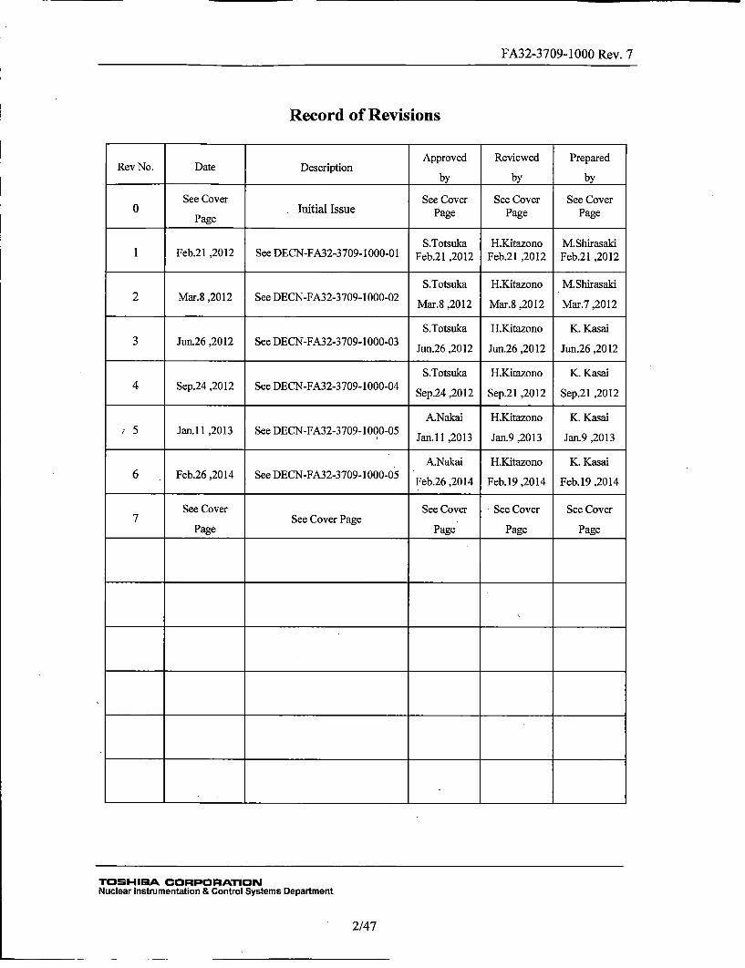
Record of Revisions
Approved Reviewed PreparedRev No. Date Description
______ ________________ by by by
See Cover See Cover See Cover See Cover_____ aeInitial Issue Page Page Page
S.Totsuka H.Kitazono M.Shirasaki
1 Feb.21 ,2012 See DECN-FA32-3709-1000-01 Feb.21 ,2012 Feb.21 ,2012 Feb.21 ,2012
S.Totsuka H.Kitazono M.Shirasaki2 Mar.8 ,2012 See DECN-FA32-3709-1000-02
Mar.8,2012 Mar.8,2012 Mar.7,2012
S.Totsuka H.Kitazono K. Kasai3 Jun.26 ,2012 See DECN-FA32-3709-1000-03 Jn2 21 u.6,02 Jn2 21
S.Totsuka H.Kitazono K. Kasai4 Sep.24 ,2012 See DECN-FA32-3709-1000-04 Sp2 21 e.1,02 Sp2 21
A.Nakai H.Kitazono K. Kasai:5 Jan.11 ,2013 See DECN-FA32-3709-1000-05 Jn1 21 a. 21 a. 21
A.Nakai H.Kitazono K. Kasai6 Feb.26 ,2014 See DECN-FA32-3709-1000-05 Fb2 21 e.9,04 Fb1 21
See Cover See Cover See Cover See Cover7See Cover Page
Page Page Page Page
I -t t *
I *t *
I -t I I I
I I
TOSHIBA CORPORATIONNuclear Instrumentation & Control Systems Department
2/47
FA32-3709-1000 Rev. 7
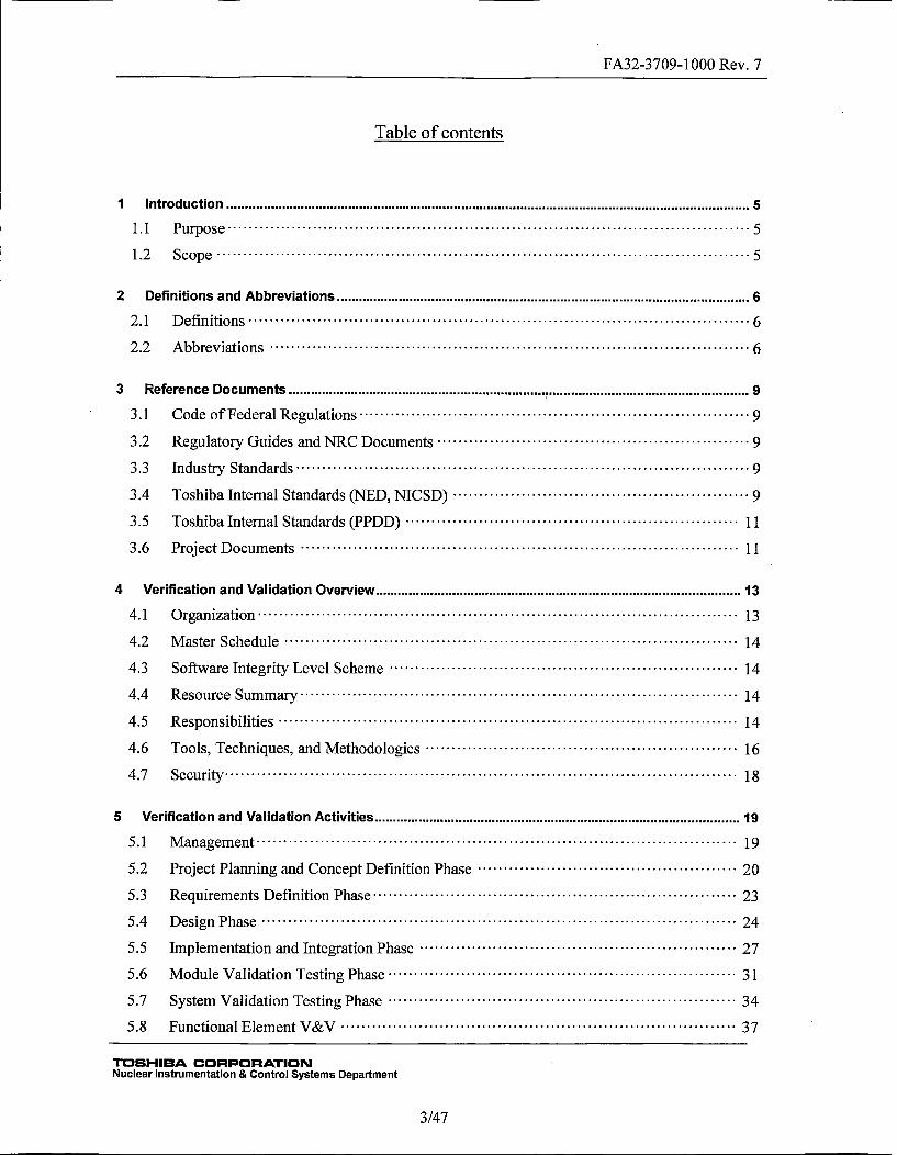
Table of contents
Introduction .................................................................................................... 5
1.1 Purpose............................................................................... 5
1.2 Scope.................................................................................5
2 Definitions and Abbreviations ............................................................................... 6
2.1 Definitions ........................................................................... 6
2.2 Abbreviations ........................................................................ 6
3 Reference Documents ........................................................................................ 9
3.1 Code of Federal Regulations ........................................................... 9
3.2 Regulatory Guides and NRC Documents ............................................... 9
3.3 Industry Standards.....................................................................9
3.4 Toshiba Internal Standards (NED, NIC SD) ............................................. 9
3.5 Toshiba Internal Standards (PPDD)................................................... 11
3.6 Project Documents .................................................................. 11
4 Verification and Validation Overview...................................................................... 13
4.1 Organization ........................................................................ 13
4.2 Master Schedule..................................................................... 14
4.3 Software Integrity Level Scheme..................................................... 14
4.4 Resource Summary .................................................................. 1]4
4.5 Responsibilities ..................................................................... 14
4.6 Tools, Techniques, and Methodologies ............................................... 16
4.7 Security ............................................................................. 18
5 Verification and Validation Activities...................................................................... 19
5.1 Management ........................................................................ 19
5.2 Project Planning and Concept Definition Phase........................................20
5.3 Requirements Definition Phase ....................................................... 23
5.4 Design Phase........................................................................ 24
5.5 Implementation and Integration Phase.................................................27
5.6 Module Validation Testing Phase ..................................................... 31
5.7 System Validation Testing Phase..................................................... 34
5.8 Functional Element V&V............................................................ 37
TOSHIBA CORPORATIONNuclear Instrumentation & Control Systems Department
3/47
FA32-3709-1000 Rev. 7
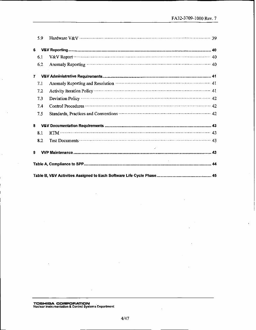
5.9 Hardware V&V ..................................................................... 39
6 V&V Reporting................................................................................................... 40
6.1 V&V Report ........................................................................ 40
6.2 Anomaly Reporting..................................................................40
7 V&V Administrative Requirements......................................................................... 41
7.1! Anomaly Reporting and Resolution...................................................41
7.2 Activity Iteration Policy..............................................................41
7.3 Deviation Policy..................................................................... 42
7.4 Control Procedures...................................................................42
7.5 Standards, Practices and Conventions ..................................... ........... 42
8 V&V Documentation Requirements ....................................................................... 43
8.1 RTM................................................................................43
8.2 Test Documents ..................................................................... 43
9 WP Maintenance ............................................................................................ 43
Table A, Compliance to SPP ..................................................................................... 44
Table B, V&V Activities Assigned to Each Software Life Cycle Phase..................................... 45
TOSHIBA CORPORATIONNuclear Instrumentation & Control Systems Department
4/47
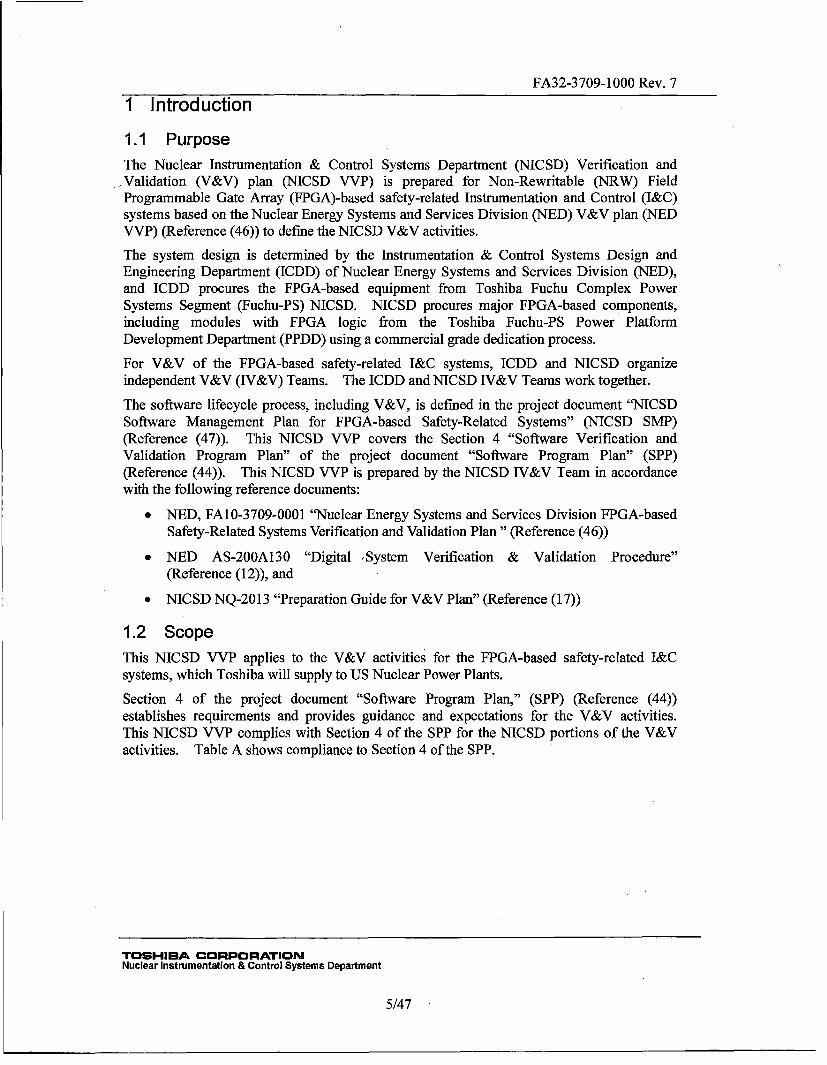
FA32-3709-1000 Rev. 71 Introduction
1.1 PurposeThe Nuclear Instrumentation & Control Systems Department (NIC SD) Verification and
.Validation (V&V) plan (NICSD VVP) is prepared for Non-Rewritable (NRW) FieldProgrammable Gate Array (FPGA)-based safety-related Instrumentation and Control (I&C)systems based on the Nuclear Energy Systems and Services Division (NED) V&V plan (NEDVVP) (Reference (46)) to define the NICSD V&V activities.
The system design is determined by the Instrumentation & Control Systems Design andEngineering Department (ICDD) of Nuclear Energy Systems and Services Division (NED),and ICDD procures the FPGA-based equipment from Toshiba Fuchu Complex PowerSystems Segment (Fuchu-PS) NICSD. NICSD procures major FPGA-based components,including modules with FPGA logic from the Toshiba Fuchu-PS Power PlatformDevelopment Department (iPPDD) using a commercial grade dedication process.
For V&V of the FPGA-based safety-related I&C systems, ICDD and NICSD organizeindependent V&V (IV&V) Teams. The ICDD and NICSD IV&V Teams work together.
The software lifecycle process, including V&V, is defined in the project document "N-ICSDSoftware Management Plan for FPGA-based Safety-Related Systems" (NICSD SMvlP)(Reference (47)). This NICSD VVP covers the Section 4 "Software Verification andValidation Program Plan" of the project document "Software Program Plan" (SPP)(Reference (44)). This NICSD VVP is prepared by the NICSD IV&V Team in accordancewith the following reference documents:
* NED, FA10-3709-0001 "Nuclear Energy Systems and Services Division FPGA-basedSafety-Related Systems Verification and Validation Plan" (Reference (46))
* NED AS-200A1 30 "Digital ,System Verification & Validation Procedure"(Reference (12)), and
* NICSD NQ-20 13 "Preparation Guide for V&V Plan" (Reference (17))
1.2 ScopeThis NICSD VVP applies to the V&V activities for the FPGA-based safety-related I&Csystems, which Toshiba will supply to US Nuclear Power Plants.
Section 4 of the project document "Software Program Plan," (SPP) (Reference (44))establishes requirements and provides guidance and expectations for the V&V activities.This NICSD VVP complies with Section 4 of the SPP for the NICSD portions of the V&Vactivities. Table A shows compliance to Section 4 of the SPP.
TOSHIBA CORPORATIONNuclear Instrumentation & Control Systems Department
5/47
FA32-3709-1000 Rev. 7
2 Definitions and Abbreviations2.1 DefinitionsFunctional Element (FE): A Functional Element is a component of digital logic that iscompletely verified and validated through full pattern testing, i.e. tests that are performed forall possible input combinations. An FE is written in Very High Speed Integrated CircuitHardware Description Language (VHDL). All VHDL source codes for theNRW-FPGA-based System solely consist of FEs and interconnect between FEs.
Module: A part of a unit. Each module consists of one or more printed circuit boards, onwhich the FPGAs and other circuitry are mounted, and a front panel.
Netlist: Description of logics created by the logic synthesis tool. A design engineerdescribes FPGA logic in the form of VHDL source codes and FEs. The logic synthesis toolconverts the VHDL source code into forms of digital circuits and outputs the resulting circuitin the form of a netlist. The layout tool transforms the netlist into physical placement ofinterconnects on the FPGA, which are represented as an FPGA fuse-map.
Unit: A major component Of FPGA-based equipment. A unit is a chassis that has front slotsand back slots to mount modules. Each unit consists of several modules. There is avertical middle plane between the front and back slots in each unit. This plane consists oftwo circuit boards. These circuit boards provide backplanes for the front and rear modules.Modules plug into the backplanes using connectors. Once a module is plugged into theappropriate connector, it exchanges data with other modules in the unit, connects to otherunits and any external field equipment, and is powered.•
Validation: Validation is used to ensure that the final product satisfies the user requirements.Validation shall be performed on the final product, although validation may be necessary orperformed prior to the final code being produced. See Section 4.2 of the SPP•(Reference (44)).
Verification: Verification consists of reviews performed on the results of each developmentphase to ensure the phase was completed appropriately and correctly. See Section 4.2 of theSPP (Reference (44)).
2.2 AbbreviationsBRR Baseline Review Report
CAR Corrective Action Request
CDR Critical Digital Review
CFR Code of Federal Regulation
CM Configuration Management
CG Commercial Grade
COTS Commercial-Off-The-Shelf
DVR Design Verification Report
ECWD Elementary Control Wiring Diagram
EDIF Electronic Design Interchange Format
EDS Equipment Design Specification
TOSH-IBA CORPORATIONNuclear Instrumentation & Control Systems Department
6/47
FA32-3709-1000 Rev. 7ES Engineering Schedule
FE Functional Element
FPGA Field Programmable Gate Array (a programmable logic device)
Fuchu-PS Toshiba Fuchu Complex Power Systems Segment
I&C Instrumentation and ControlIBD Interlock Block Diagram
ICDD Instrumentation & Control Systems Design and Engineering Department
IDE Integrated Development Environment
TED Instrumentation Electrical Diagram
IEEE Institute of Electrical and Electronics Engineers
IR Independent Reviewer
IV&V Independent Verification and Validation
MCL Master Configuration List
NED Nuclear Energy Systems and Services Division
NICSD Nuclear Instrumentation & Control Systems Department
NISD Nuclear Instrumentation Systems Development & Designing Group
NICS-QA Quality Assurance Group for Nuclear Instrumentation & Control Systems
NNR Nonconformance Notice Report
NQ Nuclear Quality (standards for NICSD)
PC Personal Computer
PCDL Project Control Document List
PDS Previously Developed Software
PM Project Manager
PPDD Power Platform Development Department
PRM Process Review Meeting
PRS Problem Reporting Sheet
PSNE Toshiba Corporation, Power Systems & Services Company, Nuclear Energy
QA Quality Assurance
QAD Quality Assurance Department
QC Quality Control
RG Regulatory Guide
RTIS Reactor Trip and Isolation System
RTM Requirements Traceability Matrix
SSAR Software Safety Analysis Report
SCAR Fuchu Site Corrective Action Request
TOSHIBA CORPORATIONNuclear Instrumentation & Control Systems Department
7/47
FA32-3709-1000 Rev. 7
SCMP Software Quality Configuration Management PlanSCSI Small Computer System Interface
SD Software Development
SDD Software Design Description
SDL Software Development Lead
SDOE Secure Development and Operational Environment
SIL Softwvare Integrity Level
SM Senior Manager
SMP Software Management Plan
SQA Software Quality Assurance
SQAP Software Quality Assurance Management Plan
SRS Software Requirements Specification
SPP Software Program Plan
SVTP Software Validation Test Plan
SVTR Software Validation Test Report
V&V Verification and Validation
VHDL Very High Speed Integrated Circuit Hardware Definition Language (Ahardware description language that defines the FPGA circuit)
VNNR Vendor Nonconformance Notice Report
VVP Verification and Validation Plan
VVR Verification and Validation Report
Table 3-1 of the NICSD SMIP is provided for a better understanding of terminologicaldifference between the SPP and NICSD SMP. This NMCSD VVP also uses Table 3-1 of theNICSD SMP.
TOSHIBA CORPORATIONNuclear Instrumentation & Control Systems Department
8/47
FA32-3709-1000 Rev. 73 Reference Documents
3.1 Code of Federal RegulationsThis NICSD VVP does not refer to the Code of Federal Regulations (CFR) directly. TheToshiba internal standards in Section 3.4 are based on the CFR.
3.2 Regulatory Guides and NRC Documents(1) Regulatory Guide 1.168
"Verification, Validation, Reviews, and Audits for Digital Computer Software Used inSafety Systems of Nuclear Power Plants." Rev. 1, 2004
(2) Regulatory Guide 1.152"Criteria for Use of Computers in Safety Systems of Nuclear Power Plants," Rev.3, July2011
Other regulatory guides may be referred to indirectly through the Toshiba internal standardsin Section 3.4.
3.3 Industry Standards(3) IEEE Std. 10 12-1998
"IEEE Standard for Software Verification and Validation"
(4) IEEE Std. 1028-1997"IEEE Standard for Software Reviews"
3.4 Toshiba Internal Standards (NED, NICSD)(5) Toshiba Nuclear Energy Systems and Services Division AS-i100A004
"Document Control Procedure"
(6) Toshiba Nuclear Energy Systems and Service Division AS-100A0 12"Preparation Procedure for Engineering Communication Sheet"
(7) Toshiba Nuclear Energy Systems and Service Division AS-200A002"Design Verification Procedure"
(8) Toshiba Nuclear Energy Systems and Services Division AS-200A0 10"Control Procedure of vendor generated documents"
(9) Toshiba Nuclear Energy Systems and Service Division AS-200A0 17"Design Planning Procedure"
(1 0) Toshiba Nuclear Energy Systems and Service Division AS-200A128"Digital System Life Cycle Procedure"
(1 1)Toshiba Nuclear Energy Systems and Service Division AS-200A129"Digital System Development Procedure"
(12) Toshiba Nuclear Energy Systems and Service Division AS-200A130"Digital System Verification & Validation Procedure"
(13) Toshiba Nuclear Energy Systems 'and Service Division AS-200A1 31"Digital System Configuration Management Procedure"
(14) Toshiba Nuclear Energy Systems and Service Division AS-300A008"NIonconformance Control and Corrective Action Procedure"
TOSHIBA CORPORATION
Nuclear Instrumentation & Control Systems Department
9/47(
FA32-3709-1000 Rev. 7
(15) Toshiba Nuclear Energy Systems and Services Division AS-300A009"Corrective Action Request Application Procedure"
(16) Toshiba Nuclear Instrumentation & Control Systems Department NQ-201 1"Procedure for FPGA Test"
(17) Toshiba Nuclear Instrumentation & Control Systems Department NQ-20 13"Preparation Guide for V&V Plan"
(18) Toshiba Nuclear Instrumentation & Control Systems Department NQ-2014"Preparation Guide for V&V Report"
(19) Toshiba Nuclear Instrumentation & Control Systems Department NQ-20 15"Preparation Procedure for RTM & RTM Report"
(20) Toshiba Nuclear Instrumentation & Control Systems Department NQ-20 19"Preparation Procedure for Test Specification"
(21) Toshiba Nuclear Instrumentation & Control Systems Department NQ-2 024"Procedure for Document Control"
(22) Toshiba Nuclear Instrumentation & Control Systems Department NQ-203 0"Procedural Standard for FPGA Products Development"
(23) Toshiba Nuclear Instrumentation & Control Systems Department NQ-203 1"Procedural Standard for FPGA Device Development"
(24) Toshiba Nuclear Instrumentation & Control Systems Department NQ-2032"Procedural Standard for Functional Element Development"
(25) Toshiba Nuclear Instrumentation & Control Systems Department NQ-203 3"Procedural Standard for FPGA Configuration Management"
(26) Toshiba Nuclear Instrumentation & Control Systems Department NQ-2003"Procedure for Control of Software Tools"
(27) Toshiba Nuclear Instrumentation & Control Systems Department NQ-203 6"Procedure for Design Control"
(28) Toshiba Nuclear Instrumentation & Control Systems Department NQ-2037"Cyber Security Procedures of Safety Related Digital System"
(29) Toshiba Nuclear Instrumentation & Control Systems Department NQ-3 005"Procedure for Evaluation of Suppliers"
(30) Toshiba Nuclear Instrumentation & Control Systems Department NQ-3 006"Procedure for Control of Nonconforming Procurement Items and Services"~
(3 1)Toshiba Nuclear Instrumentation & Control1 Systems Department NQ-3015"Test Control Procedure"
(32) Toshiba Nuclear Instrumentation & Control Systems Department NQ-3 016"Software Test"
(33) Toshiba Nuclear Instrumentation & Control Systems Department NQ-3 019"Procedure for Control of Nonconformance and Corrective Action"
(34) Toshiba Nuclear Instrumentation & Control Systems Department NQ-3 020"Control Procedure of QA Records"
TOUHIBA CORPORATIONNuclear Instrumentation & Control Systems Department
10/47
FA32-3709-1000 Rev. 7(35) Toshiba Nuclear Instrumentation & Control Systems Department NQ-400 1
"Commercial Grade Dedication"
3.5 Toshiba Internal Standards (PPDD)(36) Toshiba Power Platform Development Department E-670 19
"PPDD Procedure for Operation for Problem Reporting Sheet"
(3 7) Toshiba Power Platform Development Department E-6801 6"PPDD Procedural Standard for FPGA Products Development"
(38) Toshiba Power Platform Development Department E-680 17"PPDD Procedural Standard for FPGA Device Development"
(39) Toshiba Power Platform Development Department E-6801 8"PPDD Procedural Standard for Functional Element Development"
(40) Toshiba Power Platform Development Department E-680 19"PPDD Procedural Standard for FPGA Configuration Management"
(41) Toshiba Power Platform Development Department E-68020"PPDD Procedural Standard for Control of Software Tools for FPGA-based Systems"
(42) Toshiba Power Platform Development Department E-68027"Standard for Preparation of the Test Specification"
Notice: Upon application of above NED, NICSD and other Toshiba internal standards, thelatest version shall be used.
3.6 Project Documents(43)NRW-FPGA-Based I&C System Qualification Project, FA10-0301-0001
"Project Specific Document Control Procedure," Rev. 0
(44)NRW-FPGA-Based I&C System Qualification Project, FA 10-0501-0024"Software Program Plan," Rev. 1
(45)NRW-FPGA-Based I&C System Qualification Project, FA32-3 702-0005"Nuclear Energy Systems and Services Division FPGA-based Safety-Related SystemsSoftware Management Plan," Rev. 2
(46)NRW-FPGA-Based I&C System Qualification Project, FA32-3 709-0001"Nuclear Energy Systems and Services Division FPGA-based Safety-Related SystemsVerification and Validation Plan," Rev. 3
(47)NRW-FPGA-Based I&C System Qualification Project, FA32-3 702-1000"Nuclear Instrument & Control Systems Department Software Management Plan forFPGA-based Safety-Related Systems," Rev. 2
TOSHIBA CORPORATIONNuclear Instrumentation & Control Systems Department
11/47
FA32-3709-1000 Rev. 7(48)NRW-FPGA-Based I&C System Qualification Project, FA32-3701-1 001
"Nuclear Instrument & Control Systems Department Software Quality Assurance Planfor FPGA-Based Safety-Related Systems," Rev. 1
(49) NRW-FPGA-B ased I&C System Qualification Project, FA32-3708- 1000"Nuclear Instrument & Control Systems Department Software ConfigurationManagement Plan for FPGA-Based Safety-Related Systems," Rev. 1
TOSHIEA CORPORATIONNuclear Instrumentation & Control Systems Department
12/47
TOSHIBA CORPORATIONNuclear Instrumentation & Control Systems Department
FA32-3709-1000 Rev. 7
4 Verification and Validation Overview
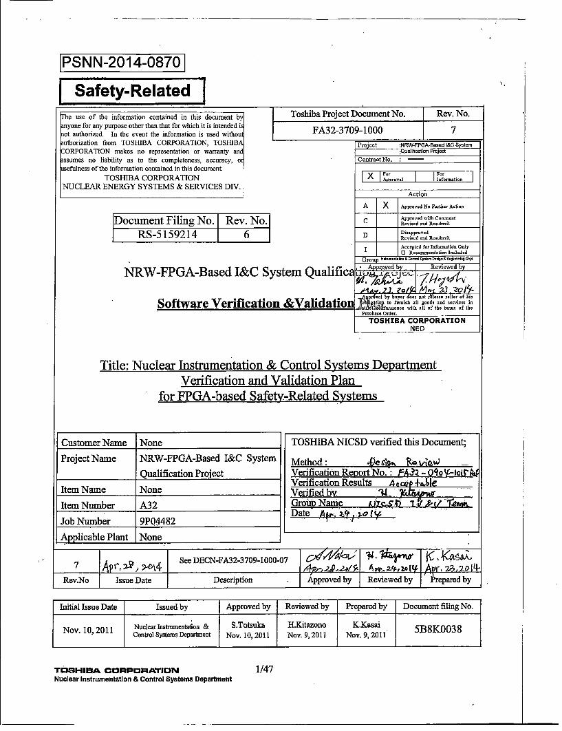
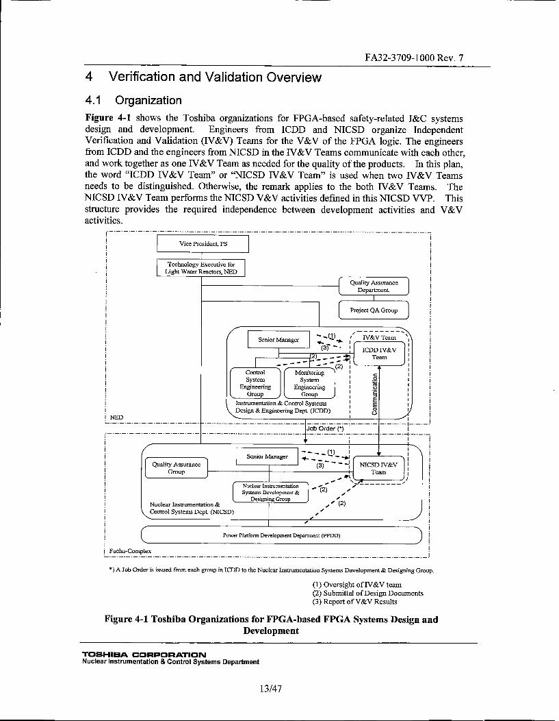
4.1 OrganizationFigure 4-1 shows the Toshiba organizations for FPGA-based safety-related I&C systemsdesign and development. Engineers from ICDD and NICSD organize IndependentVerification and Validation (IV&V) Teams for the V&V of the FPGA logic. The engineersfrom ICDD and the engineers from NICSD in the IV&V Teams communicate with each other,and work together as one IV&V Team as needed for the quality of the products. In this plan,the word "ICDD TV&V Team" or "NICSD IV&V Team" is used when two IV&V Teamsneeds to be distinguished. Otherwise, the remark applies to the both JV&V Teams. TheNICSD JV&V Team performs the NJCSD V&V activities defined in this NMCSD VVP. Thisstructure provides the required independence between development activities and V&Vactivities.
Vice President, PS
Technology Executive forLight Water Reactors, NED
SQuality Assurance I
Department.i
Senir )••(•). lI IV&V Team x I
Gop geroup I
Dein ngnein ep.(ID) ICD IVVL NED ._____ T~m , ,
SenorMaagr -I IQuaityAsurace(3)- NISDIV& I
DesigningL Group -NuclearmetatnstrumentatSytemon &Coto ysesDp.(NSDesg) nierngDp.(CD
(1b2Z *) Ovrsgh of.....tea.......... (2).Submittal..of.Design Documents.-
...... (.).Report.of.V&V.Results
FIgr4-TohbOraiainfoFGA aed G Sytm Deign an
NcerInNstrementattrnmenControl Systems De..a.tment
13/47
FA32-3709-1000 Rev. 7For the FPGA-based safety-related I&C systems, the Nuclear Instrumentation SystemsDevelopment & Designing Group (NISD) in NICSD is responsible for the design anddevelopment. The NICSD Software Development Team (NICSD SD Team) comprised ofNICSD Software Development Lead (NICSD SDL) and NISD design engineers areresponsible for software development (i.e. FPGA logic development).
4.2 Master Schedule
The NICSD IV&V activities and milestones are developed and controlled as described in theNICSD SMIP (Reference (47))
4.3 Software Integrity Level Scheme
The software integrity level (SIL) scheme shall be determined based on Table A-i of NEDAS-200A129 (Reference (11)), which is substantially equivalent to Appendix B of IEEEStd. 1012 (Reference (3)).
For safety-related FPGA logic, the SIL shall be 4 in accordance with RG 1.168(Reference (1)). All documents pertaining to safety-related FPGA design are labeled as "USSafety-Related" on the cover sheet, and are considered SIL 4 software documents. Allsoftware embedded in the FPGA-based Safety-Related I&C systems shall be developed,verified, and validated as SIL 4, safety-related software.
4.4 Resource SummaryThe Senior Manager (SM) of NICSD as the NICSD Project Manager (NICSD PM) shallprovide appropriate resources for the V&V activities defined in this MICSD VVP. Forhuman resources, the following conditions shall be met.
All NICSD IV&V Team members shall:
* Be independent of the design activities in management, budget, and resource.
* Be technically qualified for the work performed.
The NICSD IV&V Team members shall be qualified as described in the Section 15.4 of theNICSD SMIP (Reference (47)). The Section 15.4 of the NICSD SMP requires that theNICSD IV&V Lead shall determine necessary training related to the following skills, asapplicable to the job functions being performed, and require the responsible manager toschedule project specific training as "Project Specific Indoctrination/Training Course."
* Code inspection
* Software tool to be used for V&V
The NICSD IV&V Team members shall be aware of and comply with the requirement forindependence from the development organization.
This NICSD VVP includes some special procedural requirements to PPDD. NICSD shallput these requirements in the procurement specification to the PPDD.
4.5 Responsibilities
The SM of NICSD as the NICSD PM shall assign the NICSD IV&V Lead, who leads theV&V activities encompassing the NICSD engineering/design work in accordance with theNMCSD SMIP (Reference (47)). The NICSD IV&V Lead assigns the other IV&V Team
TOSH-IBA CORPORATIONNuclear Instrumentation & Control Systems Department
14/47
FA32-3709-1000 Rev. 7members of NICSD who were trained as described in Section 4.4 of this VVP.
The NICSD IV&V Lead is equivalent to the Software V&V Lead described in the SPP(Reference (44)). In addition to the responsibilities defined in the NICSD SMP, the NICSDIV&V Lead has responsibilities listed in Section 4.2.4 of the SPP (Reference (44)), includingreview of Secure Development and Operational Environment (SDOE) implementation. SDOEis defined in the SPP and in Regulatory Guide 1.152 (Reference (2)).
The following positions, created as necessary during the project, are administratively assignedto the Software V&V Lead, as necessary. If these positions are not assigned, the SoftwareV&V Lead shall be responsible for the activities listed below:
Software Test Lead -The Software Test Lead shall be responsible for defining the softwareand systems test plans, procedures, and cases. Each Softwcare Test Lead shall beresponsible for the overseeing the performance of testing and test engineers, working withthe NICSD Software Development Lead (SDL) to resolve test anomalies, and settingboundaries and requirements for retest activities.
Baseline Review - The NICSD IV&V Team ensures that activities are properly performedand documented at each phase in the software life cycle. The NICSD IV&V Team isresponsible for verifying all work products are completed, placed under configurationcontrol, and records updated to reflect completion of a life cycle phase, reporting to theNICSD Quality Assurance Group. Work products to be subject to baseline review shall bedefined in the Software Configuration Management Plan. The NICSD IV&V Team shallprepare a Baseline Review report at the result of baseline review. Section 4.6.3 explainsBaseline Review.
NED AS-200A130 (Reference (12)) defines the responsibilities in the V&V activities of bothICDD and NICSD. NQ-2030 (Reference (22)) defines the responsibilities in the NICSDV&V activities of the NICSD engineering and design work.
The Preparer(s) of the NICSD VVP and V&V reports (VVR) shall:
* Be part of the NICSD IV&V Team.
* Not have contributed to the design.
* Be technically qualified for the work performed, and knowledgeable in thetechnologies and methods used in the design.
The NICSD IV&V Team performs independent reviews of the NICSD and PPDD designdocuments.
The NICSD IV&V Team may also oversee the work of NICSD and PPDD, to verify that theyare working in compliance with applicable internal standards, and to evaluate that their workis technically acceptable for safety-related use.
The NICSD Soft-ware Quality Assurance (SQA) Team (NICSD SQA Team) will conductoversight of the NICSD IV&V Team activities.
TOSHIBA CORPORATIONNuclear Instrumentation & Control Systems Department
15/47
FA32-3709-1000 Rev. 74.6 Tools, Techniques, and Methodologies
The NICSD IV&V Team will use several commercial software tools for the V&V activities ofthe FPGA-based safety-related I&C systems. The NICSD SMIP (Reference (47)) describessoftware tools used for engineering.
4.6.1 Verification and Validation
The NICSD 1V&V Team shall review the Requirements Traceability Matrix (RTM) and theSoftware Safety Analysis Reports (SSAR), Equipment Design Specification (EDS), SystemTest Procedures, System User's Manuals, Elementary Control Wiring Diagrams (ECWD),Unit Detail Design Specifications, Unit User's Manuals, Module Design Specifications,Module Test Procedures, FPGA Design Specifications, and FPGA Test Procedures. Thisreview may be performed on either the printed or the electronic documents. ToshibaNUPDM will be used for distribution and archives of the documents. And a set of standardbusiness software tool will be used for the review.
Document review is a method of V&V, and shall be performed in accordance with NEDAS-200A002 (Reference (7)), AS-200A130 (Reference (12)), and NQ-2036 (Reference (27)).IEEE Std. 1012 (Reference (3)), and IEEE Std. 1028 (Reference (4)) provide guidance for thereviews.
AS-200A002 requires to prepare a Design Verification Report (DVR) including a commentbox. Section 4.2 of AS-200A002 describes that when the verifier (the verifier inAS-200A002 is called Independent Reviewer (IR) in this VVP) discovers problems, theverifier shall return the DVR with the comments. If the IR discovers so many problems, or aso complex problem that cannot be described in the limited space of the comment box, the IRmay use separate comment sheets.
Document review performed as technical review to confir-m that:
a) The document conforms to its upstream requirements
b) The document adheres to regulations, standards, guidelines, plans, and proceduresapplicable to the project
c) Changes to the document are properly implemented and affect only those system areasidentified by the change specification
For planning documents, implementation process documents, and design outputs includingSSAR and VVR, document review shall be performed for completeness, consistency,correctness, and verifiability as applicable. Appendix A of the SPP "Terms and Definition"provides definitions for these words.
4.6.2 Requirements Traceability Activities
Requirements Traceability Matrices (RTMs) shall be generated by the NICSD SD Team andPPDD design engineers and reviewed by the IV&V Team to ensure the software hascompletely, accurately, correctly, and consistently addressed the requirements. The RTMshall provide traceability, verification, and validation of requirements.
TOSHIBfA CORPORATIONNuclear Instrumentation & Control Systems Department
16/47
FA32-3709-l000 Rev. 74.6.3 Baseline Reviews
The NJCSD IV&V Team shall perform Baseline Reviews at the conclusion of each phase inthe software life cycle to ensure that the required activities during that phase were completed.The Baseline Review shall confirm that planned products including design documents, testdocuments, VHDL source codes, netlists, fusemaps, test reports, RTMs, SSARs, and V&VReports were prepared, that appropriate reviews were performed for these products, and thatthese products were documented and maintained under configuration management (CM).
The NICSD lV&V Team shall confirm the following:
* The NICSD design activities are performed, and the design outputs are prepared asplanned in the NICSD SMPW.
* NICSD V&V activities are performed as planned in this NICSD VVP.
* The NICSD design outputs are documented and controlled in accordance withINQ-2036 (Reference (27)).
All software life cycle activities for a given phase shall be completed prior to initiating abaseline review. Each anomaly or nonconformance found in baseline reviews shall beresolved through the software life cycle processes. Each of the baseline reviews shallconfirm disposition of design, documentation, review, and any other nonconformanceidentified during the phase, or shall track any unresolved nonconformance through toresolution if the nonconformance cannot be resolved in that phase.
The NICSD IV&V Team shall document the result of a baseline review in a Baseline ReviewReport (BRR), and report it to the NICSD SQA Team for review and approve it as QA record.In accordance with Section 4.2.6.6 of the SPP (Reference (44)), the BRR shall:
* Describe the review scope,
* Identify the reviewers,
* Identify the persons contacted during the review,
* Document the outputs and versions reviewed,
* Contain a summary of the review results, and
* Describe recommendations and findings.
4.6.4 FPGA development Tool
The NICSD IV&V Team will use the following FPGA development tools for V&Vactivities..
1. Designer tool
2. Synplify® tool
3. Netlist Viewer tool
4. ModelSim® tool
These tools are commercial software tools, that PPDD uses for development of FPGA basedmodules. Section 8.1.2 of the NICSD SMLP (Reference (47)) describes the tools as well asmethods used to accept use of the tools for FPGA-based safety systems for nuclear powerplants.
TOSHIBA CORqPORATIONNuclear Instrumentation & Control Systems Department
17/47
FA32-3709-1000 Rev. 7In addition to the above tools, NICSD uses office productivity tools, database software, oreditor tools. These software tools are SIL 1 software, and do not need special controlprocedure.
4.6.5 Test Equipment
NICSD shall control the software tools as described in the NJCSD SMP.
The NICSD IV&V Team will review and approve the PPDD work products associated withFPGA review and test.
The NICSD IV&V Team shall document the result of a software tool in a V&V Report.
NICSD expect that PPDD uses the following test equipment for the module testing at the
factory:
* Signal-generating equipment - Signal-generating equipment is used to generate testsignal to modules.
* Signal-recording equipment - Signal-recording equipment is used to record responsesignals from the module.
* Test Personal Computer (PC) - One or more PCs are used to control thesignal-generating equipment and the signal-recording equipment. The Test PCrecords the generated and response signals.
NICSD will use test equipment for the verification and validation activities for the units andthe system. The test equipment is similar to that of PPDD. The NICSD IV&V Team willevaluate adequacy of these tools.
Test equipment software is not embedded in any FPGA-based safety-related systems.
4.6.6 Metrics
The NICSD TV&V Team should monitor and track the following metrics through the lifecyclephases described in Section 5 to evaluate the product quality.
* Number of changes applied for the design documents
* Number of open items carried to the next phase
* Number of open items closed in the current phase
* Number of Site Corrective Action Requests (SCARs)
* Number of Site Nonconformance Notice Reports (SNNRs)
* Number of problems found during V&V testing
4.7 Security
NICSD takes appropriate measures to ensure Secure Development and OperationalEnvironment (SDOE) as addressed in the SPP. The requirements for the NICSD SDOE are•mapped and described in the NQ-2037 (Reference (28)). The NICSD IV&V Team shallverify that the cyber security requirements described in NQ-2037 are correctly reflected inthe software life cycles.
TO:SHIBA CORPORATIONNuclear Instrumentation & Control Systems Department
18/47
FA32-3709-1000 Rev. 7
5 Verification and Validation ActivitiesTable B of this NICSD VVP describes V&V activities assigned to each Software Life CyclePhases.
The following sub-sections describe the V&V activities for the NICSD scope.
5.1 Management
5.1.1 Management of V&V
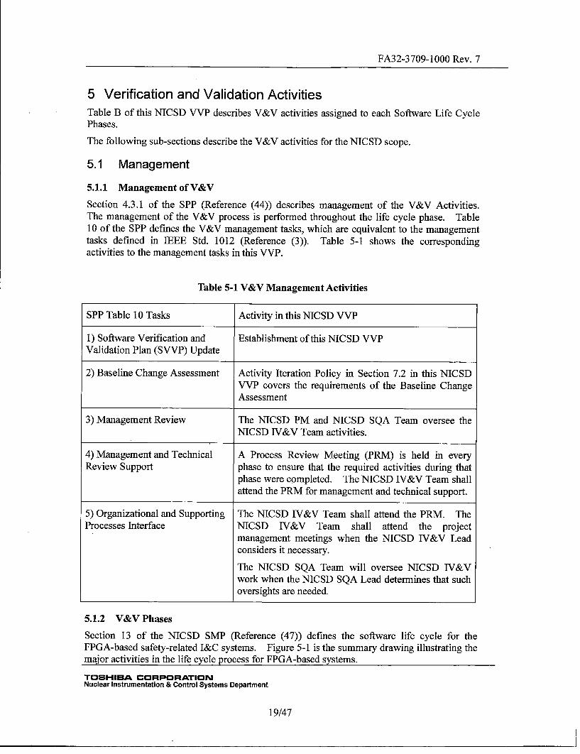
Section 4.3.1 of the SPP (Reference (44)) describes management of the V&V Activities.The management of the V&V process is performed throughout the life cycle phase. Table10 of the SPP defines the V&V management tasks, which are equivalent to the managementtasks defined in TEEE Std. 1012 (Reference (3)). Table 5-1 shows the correspondingactivities to the management tasks in this VVP.
Table 5-1 V&V Management Activities
SPP Table 10 Tasks Activity in this NICSD VVP
1) Software Verification and Establishment of this NICSD VVPValidation Plan (SVVP) Update
2) Baseline Change Assessment Activity Iteration Policy in Section 7.2 in this NICSDVVP covers the requirements of the Baseline ChangeAssessment
3) Management Review The NICSD PM and NICSD SQA Team oversee theNICSD IV&V Team activities.
4) Management and Technical A Process Review Meeting (PRM) is held in everyReview Support phase to ensure that the required activities during that
phase were completed. The NICSD IV&V Team shallattend the PRM for management and technical support.
5) Organizational and Supporting The NICSD IV&V Team shall attend the PRM. TheProcesses Interface NICSD IV&V Team shall attend the project
management meetings when the NICSD IV&V Leadconsiders it necessary.
The NICSD SQA Team will oversee NICSD TV&Vwork when the NICSD SQA Lead determines that suchoversights are needed.
5.1.2 V&V Phases
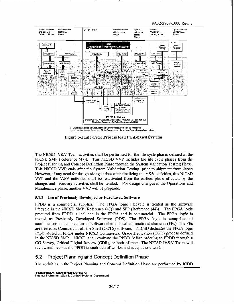
Section 13 of the NICSD SMiP (Reference (47)) defimes the software life cycle for theFPGA-based safety-related I&C systems. Figure 5-1 is the summary drawing illustrating themajor activities in the life cycle process for FPGA-based systems.
TOSHIBA CORPORATIONNuclear Instrumentation & Control Systems Department
19/47
FA32-3709-1000 Rev. 7Project Planningand ConceptDefinition Phase
RequirenmentsDefinitionPhase
Design PhaseImplementation& IntegrationPhone
ModuleValidationTestingPhase
SystemValidationTesting Phase
Operations endMaintenancePhase
nycom oel;n NED iII~ I I purism, caugo100, Appendix B I ~ Pro ~i or ~AZt~iti nesrasan cuangesas
- - * Tasting Regaled
IV5V easiest iV&V Reaec IV&V Recess iV&V Rosiest IV&V Resiecs IV&V Renless
IV&V Recess iV5V Recess - IV&V Rosiest IV&V RosIest oseunceanuea as
eanuirod
cq snieni Fl'caagn 00
onececanon castled NICSD VatidatianTeat ValidaSanOcCen ,. Plan Os is
'5t< ~ oP~ dicaSan . Appendix B QA Program Act~vitie~I ~' l~'
I sesree-~ rant IV&V Rosiest IV&V Recess
Procurement Integrate,neonraing
- ardor 5 - . . as a - trepectarrmOan ~
F t 4I I Module cadgn ldodre Test
Modade MCcL (saiwas re
Sein FPoA Tat Prad~sr,On.M FPGATesS Reparts,
Modusn Test Praanidsr
PPDD ActivitiesS(Per PPDD lDeorocedres, with Special Procurement Requirements
I Mandating Processes Sufficient tar Appendin BQA )
(1) Unit Detailed Design Spec. includes Software Requirements Specification.(2), (3) Module Design Spec. and FPGA Design Spec. include Software Design Description.
Figure 5-1 Life Cycle Process for FPGA-based Systems
The NICSD JV&V Team activities shall be performed for the life cycle phases defined in theNICSD SNIP (Reference (47)). This NICSD VVP includes the life cycle phases from theProject Planning and Concept Definition Phase through the System Validation Testing Phase.This NTCSD VVP ends after the System Validation Testing, prior to shipment from JapanHowever, if any need for design change arises after finalizing the V&V activities, this NICSDVVP and the V&V activities shall be reactivated from the earliest phase affected by thechange, and necessary activities shall be iterated. For design changes in the Operations andMaintenance phase, another VVP will be prepared.
5.1.3 Use of Previously Developed or Purchased Software
PPDD is a commercial supplier. The FPGA logic lifecycle is treated as the softwarelifecycle in the NICSD SNIP (Reference (47)) and SPP (Reference (44)). The FPGA logicprocured from PPDD is included in the FPGA and is commercial. The FPGA logic istreated as Previously Developed Software (PDS). The FPGA logic is comprised ofcombinations and connections of software elements called functional elements (-FEs). The FEsare treated as Commercial-off-the Shelf (COTS) software. NICSD dedicates the FPGA logicimplemented in FPGA under NICSD Commercial Grade Dedication (CGD) process definedin the NICSD SNIP. NICSD shall evaluate the PPDD before ordering to PPDD through aCG Survey, Critical Digital Review (CDR), or both of them. The NICSD IV&V Team willreview and oversee the PPDD in each step of works, and accept those works.
5.2 Project Planning and Concept Definition Phase
The activities in the Project Planning and Concept Definition Phase are performed by ICDD
TOSHIBA CORPORATIONNuclear Instrumentation & Control Systems Department
20/47
FA32-3709-l000 Rev. 7and NICSD. The activities of NICSD in the Project Planning and Concept Definition Phaseare described in this section.
During this phase, NICSD generates the Equipment Design Specification (EDS) including thedesign basis and applicable regulations and industry practices in the design, and starts themaster configuration list (MCL). The MCL started in this phase is updated throughout thesoftware life cycle.
Table A of the NICSD SMP (Reference (47)) lists the outline of the output documents of theNICSD V&V activities.
5.2.1 Preparation of NICSD VVPThe NICSD TV&V Team shall prepare this NICSD VVP in accordance with NQ-20 13(Reference (17)), coordinating the plan with the ICDD VVP. The NICSD IV&V Lead shallreview this NICSD VVP.For the procedures to be used for the document review, see Section 4.6.1 in this NICSD VVP.
The NICSD IV&V Team delivers the NICSD VVP to the ICDD TV&V Team for review.
5.2.2 Preparation of Software Test Plan
The NICSD IV&V Team shall prepare a Software Test Plans as described in Section 9 of theSPP (Reference (44)). The NICSD IV&V Team uses the EDS as the base to prepare theSoftware Test Plan. The scope of tests covered by the Softwvare Test Plan is as follows.
* FPGA Testing* Module Validation Testing* System Validation Testing
The Software Test Plan defines the scope, approach, resources, and schedule of the testingactivities, and shall require generation of the following documents:
* Software Validation Test Plan (SVTP)* Test Specification (including Test Design, Test Case)* Test Procedure* Test Report
5.2.3 Document Reviews
The NICSD IV&V Team shall perform independent reviews of the documents, which arelisted in Table A of the NICSD SMIP marked "DVR" in the "Other Outputs" column. Forthe procedures to be used for the document review, see Section 4.6.1 in this NICSD VVP.
The NMCSD IV&V Team reviews the documents for the V&V activities in this phase referringto the methods and procedures described in Table 11 of the SPP. The Table B is providedfor a better understanding of terminological difference between the SPP and NICSD VVIP.
5.2.4 Project Planning and Concept Definition Phase RTM efforts
(1) Preparation of the RTM
The NICSD SD Team shall update the Project Planning and Concept Definition Phase RTMdelivered by JCDD to maintain the traceability between the ICDD requirements and the EDSin accordance with NQ-20 15 (Reference (19))
The NICSD SD Team traces the upper level requirements in the NED documents to the EDS,
TOSH-IBA CORPORATIONNuclear Instrumentation & Control Systems Department
21/47
FA32-3709-1000 Rev. 7and traces the EDS requirements back to the upper level requirements.
The RTM efforts ensure the following:
* The requirements are traced "forwards" from the upstream documents to thedownstream documents.
* The downstream requirements are traced back to the upstream documents.
See Section 8.1 for preparation of RTM.
(2) Compilation of the Project Planning and Concept Definition Phase RTM report
The NICSD SD Team summarizes open items revealed by the RTM efforts. The NICSD SDTeam must resolve these items to the satisfaction of the RTM preparer(s).
The NICSD IV&V Team shall review the RTM for work performed by NICSD.
The NICSD IV&V Team shall describe the result of RTM review in the V&V Report for thisphase.
5.2.5 Security Review
The NICSD IV&V Team shall review that the cyber security requirements described inNQ-2037 (Reference (28)) and the SPP are correctly reflected in the software life cycles.
The NICSD IV&V Team shall perform independent review (IR) of the EDS and SSARs, andensure that appropriate cyber security requirements complying with NQ-203 7 and the SPP areincluded in the EDSs and SSARs. In addition, the MICSD IV&V Team shall confirm that anappropriate secure development enVironment is established. The result of Security Reviewshall be described in the V&V Report.
5.2.6 Project Planning and Concept Definition Phase V&V Reporting
The NICSD IV&V Team shall prepare the Project Planning and Concept Definition PhaseV&V Report summarizing the V&V activities performed for this Project Planning andConcept Definition Phase. This report will be extended at the end of each phase to add theresults of each phase report. At the end of the lifecycle, the final report will thus contain theresults from all lifecycle phases.
The NICSD V&V Report shall include:
(1) References to the reviewed documents(2) References to the Design Verification Reports (DVR)(3) Reference to the Project Planning and Concept Definition Phase RTM (NICSD
portion)(4) Open items revealed in the RTM efforts(5) Result of the Security Review*(6) Result of the SSAR review(7) Metrics described in Section 4.6.6(8) Any findings, recommendations, or suggestions to reduce any risks identified in the
V&V activities
The NICSD IV&V Team delivers the NICSD V&V Report to the ICDD JV&V Team forreview.
TOSHIBA CORPORATIONNuclear Instrumentation & Control Systems Department
22/47
FA32-3709-1000 Rev. 75.2.7 Baseline Review
To complete the Project Planning and Concept Definition Phase, the NICSD IV&V Teamshall perform baseline reviews at the phase end as described in Section 4.6.3. The NICSDIV&V Team shall issue a Baseline Review Report (BRR) documenting the results of theBaseline Review and report to the NICSD SQA Team for review and approval as QA record.
5.3 Requirements Definition Phase
The development activities in the Requirements Definition Phase are performed by NIC SD.In the Requirements Definition Phase, the NICSD SD Team develops a Unit Detailed DesignSpecification. This specification addresses software and hardware requirementsaccomplished by unait design, and provides necessary functional requirements for moduledesign.
Table A of the NICSD SNIP (Reference (47)) lists the outline of the output documents of theMICSD V&V activities.
5.3.1 Document Reviews
The NICSD IV&V Team shall perform independent reviews of the documents, which arelisted in Table A of the NICSD SMIP (Reference (47)), and marked "DVR" in the "OtherOutputs" column. For the procedures to be used for the document review, see Section 4.6.1in this NICSD VVP.
The NICSD 1V&V Team reviews the documents for the V&V activities in this phase referringto the methods and procedures described in Table 12 of the SPP (Reference (44). The TableB is provided for a better understanding of terminological difference between the SPP andNICSD VVP.
5.3.2 Requirements Definition Phase RTM efforts
(1) Preparation of Requirements Definition Phase RTM
The NICSD SD Team performs the Requirements Definition Phase RTM efforts.
The RTM efforts ensure the following:
* The requirements are traced "forwards" from the Project Planning and ConceptDefinition Phase to this phase design documents.
* The requirements are traced back from this phase to the Project Planning and ConceptDefinition Phase. That is, all requirements listed in this phase are covered by theProject Planning and Concept Definition Phase requirements, and no newrequirements have been created in this phase.
In this Requirements Definition Phase, some requirements from the Project Planning andConcept Definition Phase are allocated to hardware. These hardware requirements are alsotraced. In addition, the RTM efforts must address interface requirements among units, andamong modules.
(2) Compilation of the Requirements Definition Phase RTM report
The NICSD IV&V Team shall review the RTM.
The NIC SD TV&V Team shall describe the result of RTM review in the V&V Report for this
TOSHIIEA CORPORATIONNuclear Instrumentation & Control Systems Department
23/47
FA32-3 709-1000 Rev. 7phase.
5.3.3 Security Review
The NICSD IV&V Team shall review that the cyber security requirements described inNQ-2037 (Reference (28)) and the SPP (Reference (44) are correctly reflected in the softwarelife cycles.
The NICSD IV&V Team shall perform independent review (TR) of the Unit Detailed DesignSpecifications and SSARs, and confirm that appropriate cyber security requirementscomplying with NQ-203 7 and the SPP are included in the Unit Detailed Design Specifications.The result of Security Review shall be described in the V&V report.
5.3.4 Requirements Definition Phase V&V Reporting
The NICSD JV&V Team shall prepare the Requirements Definition Phase V&V Reportsummarizing the V&V activities performed for this Requirements Definition Phase.
The NICSD V&V Report shall include:
(1) Reference to the reviewed documents
(2) Reference to the Design Verification Reports (DVR)
(3) Reference to the Requirements Definition Phase RTM
(4) Open items revealed in the RTM efforts
(5) Results of the Security Review
(6) Results of the SSAR review
(7) Metrics described in Section 4.6.6
(8) Any findings, recommendations, or suggestions to reduce any risks identified in theV&V activities
The NICSD LV&V Team delivers the NICSD V&V Report to the ICDD IV&V Team forreview.
5.3.5 Baseline Review
To complete the Requirements Definition Phase, the NICSD IV&V Team shall perform
baseline reviews at the phase end as described in Section 4.6.3. The NICSD IV&V Teamshall issue a BRR documenting the results of the Baseline Review and report to the NICSDSQA Team for review and approval as QA record.
5.4 Design PhaseNICSD procures the FPGA-based modules from PPDD. In the design phase, PPDDproduces the Module Design Specifications and the FPGA Design Specifications, whichdefine the FPGA logic design, in accordance with PPDD procedure E-68017 (Reference (38)).A special characteristic of the Toshiba FPGA-based I&C systems is that FPGA logic consistsof the verified and well proven functional elements (FEs) and interconnects between FEs. AllFE are generated by PPDD. The V&V activities for FEs are described separately in Section5.8
Table A of the NICSD SMP (Reference (47)) lists the outline of the output documents of
TOSHIBA CORPORATIONNuclear Instrumentation & Control Systems Department
24/47
FA32-3709-1000 Rev. 7these V&V activities.
5.4.1 Preparation of SVTP
The NICSD JV&V Team shall initiate preparation of a Software Validation Test Plan (SVTP)in accordance with this NICSD VVP and in Section 9 of the SPP (Reference (44)). TheSVTP shall outline the methodology of how various tests will be used to validate that theintegrated software meets the requirements stated in the EDS and the Unit Detailed DesignSpecification.
The SVTP can include a plan for Platform Factory Test (PFT), if necessary.
This activity shall be initiated in this phase to ensure completion prior to the SystemValidation Testing Phase.
5.4.2 Document Reviews
During this phase, the NICSD TV&V Team is involved in reviewing each PPDD workproduct. The NICSD IV&V Team ensures the quality and completeness of each workproduct and its readiness for CGD.
The NICSD IV&V Team shall perform independent reviews of the documents, which arelisted in Table A of the NICSD SMLP (Reference (47)), and marked "DVR" in the "OtherOutputs" column. For the procedures to be used for the document review, see Section 4.6.1in this NICSD VVP.
The NICSD IV&V Team reviews the documents for the V&V activities in this phase referringto the methods and procedures described in Table 13 of the SPP. The Table B is providedfor a better understanding of terminological difference between the SPP and NJCSD VVP.
The NICSD TV&V Team shall review design and test documents submitted by PPDD. PPDDuse PPDD standard E-680 17 (Reference (38)) that has equivalent requirements for FPGAdesign, coding and testing specified in NICSD Standard NQ-203 1 (Reference (23)).
The NICSD IV&V Team shall confirm that the FPGA logic is designed adhering to thedesign rules given in the NICSD Standard NQ-203 1, Appendix A, as well as confirming thatguidance provided by the FPGA vendor, Microsemi Corporation, in Application Notes for thechosen FPGA integrated circuit is appropriately incorporated in the design. In particular, theFPGA logic consists of the verified and well proven FEs, and the interface to each FE isconsistent with the FE specification. The NICSD TV&V Team shall review and approve theresults of the PPDD review.
The NICSD TV&V Team shall check that the FE documents are appropriately maintained asdescribed in Section 5.8.
The NICSD IV&V Team shall confirm that the requirements in PPDD Standard E-68017 areequivalent to the requirements in NICSD Standard NQ-203 1 through the CG Survey report orCDR report, or other means.
5.4.3 Design Phase RTM efforts
(1) Preparation of Design Phase RTM
The PPDD design engineers prepare the RTM to maintain the traceability from the unit designto the module design and to the FPGA. The RTM efforts ensure the following:
* The requirements are traced "forwards" from the Requirements Definition Phase to
TOSH-IEA CORPORATIONNuclear Instrumentation & Control Systems Department
2 5/47
FA32-3709-1000 Rev. 7
this phase design documents. That is, all requirements in the unit design areallocated to modules mounted in the unit, and requirements in each module design areallocated to FPGAs included in the module.
* The requirements are traced back from this phase to the Requirements DefinitionPhase. That is, all requirements listed in this phase are covered by the RequirementsDefinition Phase, and no new requirements have been created in this phase.Note: An FPGA design may include maintenance or test purpose circuits. Inclusionof these kinds of circuits must be described in the Module Design Specification asexceptions. The NICSD IV&V Team shall confirm that these circuits do not causeany adverse effects to the module functions.
(2) Compilation of the Design Phase RTM report
The NICSD IV&V Team shall review the RTM prepared by PPDD.
The NICSD SD Team shall update the RTM of the Requirements Definition Phase based onthe RTM prepared by PPDD.
The NICSD IV&V Team shall describe the result of RTM review in the V&V Report for thisphase.
5.4.4 Security Review
The NICSD JV&V Team shall verify that the cyber security requirements described inNQ-2037 (Reference (28)) and the SPP (Reference (44)) are correctly reflected in thesoftware life cycles.
The NICSD IV&V Team shall perform independent review (liR) of the Module DesignSpecifications, FPGA Design Specifications and S SARs, and confirm that appropriate cybersecurity requirements complying with NQ-2037 and the SPP are included in the ModuleDesign Specifications and FPGA Design Specifications. In addition, the NICSD IIV&VTeam shall confirm that an appropriate secure development environment is established inPPDD. The result of the Security Review shall be described in the V&V Report.
5.4.5 Design Phase V&V Reporting
The NICSD IV&V Team shall prepare the Design Phase V&V Report summarizing the V&Vactivities pefformed for this Design Phase.
The NICSD V&V Report shall include:
(1) Reference to the reviewed documents
(2) Reference to the Design Verification Reports (DVR)
(3) Reference to the results of the FE document and the soft-ware tool control checks, seeSection 5.8
(4) Reference to the Design Phase RTM
(5) Open items revealed in the RTM efforts
(6) Results of the Security Review
(7) Results of the SSAR review
(8) Metrics described in Section 4.6.6
(9) Any findings, recommendations, or suggestions to reduce any risks identified in the
TOSH-IIA 'CORPORATIONNuclear Instrumentation & Control Systems Department
26/47
FA32-3709-1000 Rev. 7V&V activities
The NICSD TV&V Team delivers the NICSD V&V Report to the ICDD IV&V Team forreview.
5.4.6 Baseline Review
To complete the Design Phase, the NICSD IV&V Team shall perform baseline reviews at thephase end as described in Section 4.6.3. The NICSD IV&V Team shall issue a BRRdocumenting the results of the Baseline Review and report to the NICSD SQA Team forreview and approval as QA record.
5.5 Implementation and Integration Phase
In the Implementation and Integration Phase, the FPGAs are developed by PPDD in thefollowing three steps:
Step 1 VHDL Source Coding:
The PPDD design engineers generate VHDL source code that implements the functionalrequirements written in the FPGA Design Specification in accordance with PPDDprocedure E-680 17 (Reference (38)). In generating the VHDL source code, the PPDDdesign engineers use editor tools. Since subsequent activities adequately verify andvalidate the VHDL source code, no V&V activities are necessary for the editor tools.
Step 2: FPGA Implementation
The PPDD design engineers convert the VHDL source code into netlists using theSynplify® tool, a logic synthesizer. Netlists of FEs used in the design are taken from thePPDD FE library, and integrated into a single netlist by the Designer tool supplied byMicrosemi.
To detect errors in the netlists, which may be undetected by the software tools, and errors inthe source code, the NICSD IV&V Team confirms logic diagrams from the netlist, andinspects the logic diagrams comparing with the VHDL source code. The logic diagramsare drawn by the Netlist Viewer tool, which is supplied by Microsemi, but is independentof the Synplify® tool.
After the inspection, the PPDD design engineers convert the netlists into a placed, routednetlist, called fuse map, and embeds the fuse map into a test purpose FPGA.
To minimize risks associated with timing, the PPDD design engineers perform timinganalysis and simulation during their design process. This two-part process includes statictiming analysis and dynamic timing simulation. Static timing analysis evaluates the setupand hold times on each path within the FPGA design. The Designer software toolevaluates the propagation delay to each element in the code in order to determine eachtiming path in the code. The result from this static analysis can be interpreted by theModelSim® tool. The PPDD design engineers then use ModelSim® tool to validate thedesign with dynamic simulation, using accurate propagation delays.
Step 3: FPGA Testing
PPDD performs testing on the FPGAs as defined below. The NICSD IV&V Teamreviews the FPGA Test Procedure prepared by PPDD.
TOSHIBA CORPORATIONNuclear Instrumentation & Control Systems Department
2 7/47
FA32-3709-1000 Rev. 7
This testing includes:a) Simulation of the fuse map generated in Step 2, and
b) FPGA Testing using the test purpose FPGA produced in Step 2.
The PPDD design engineers perform FPGA Testing using the ModelSim® tool, and thePinPort device. The ModelSim® tool is not only used in simulation, but also in FPGATesting using an FPGA chip that embeds target FPGA logic for testing. The ModelSim®tool generates inputs to the FPGAs according to the test vectors that are prepared prior tothe FPGA Testing.
The PPDD engineers use ModelSim® tool to simulate the internal operation of the logic.The ModelSim® tool provide the PPDD engineer with the capability to watch individualsignals within the FPGA and validate that timed FPGA logic works as the engineer intends.These tests verify that the FPGA timing constraints are satisfied, and that additional PPDDtiming rules are satisfied. The NICSD IV&V Team shall review FPGA Test Reportsdescribing the result of the FPGA Testing.
After the test is satisfactorily performed using both the simulation software tool and animplementation in an FPGA, the FPGA logic is considered qualified, and registered. Thusthe baseline for the registered FPGA logic is established.
The qualified FPGA logic must be implemented in an FPGA integrated circuit prior tobeing soldered to a module printed circuit board.
All testing results are brought into the NJCSD Appendix B program and placed underconfiguration management at the successful conclusion of testing and acceptance of thattesting by NICSD.
Table A of the NICSD SMIP (Reference (47)) lists the outline of the outputs of these V&Vactivities.
The NICSD JV&V Team should observe PPDD activities to verify that PPDD work inaccordance with their procedures and NICSD's expectations. These observations could becoordinated with NICSD SQA Team. Results of the observation shall be documented in theV&V Report. If the NICSD IV&V Team finds any nonconformance in PPDD's activities,the NICSD IV&V Team shall issue a SCAR documenting the rejection of the PPDD workproduct.
5.5.1 VHDL Source Code Reviews
The NICSD IV&V Team shall review the source code to verify correctness, consistency,completeness, accuracy, and traceability to the design specifications in accordance withNQ-2031 (Reference (23)) and Sections 13.4.3 and 14.5.1 of the NICSD SMIP (Reference(47)). The results of these reviews must be documented using a Source Code Review Sheet.These verifications must include (at a minimum) review of the FPGA source code written inVHDL (or equivalent configuration information) to ensure that the source code matches whatwas specified in the FPGA Design Specification (Soft-ware Design Description). Thereviewer may use software development tools such as a VHDL Simulator in addition totraditional techniques described in IEEE Std 1028 (Reference (4)).
5.5.2 Logic Synthesis and Layout
The PPDD design engineers convert the VH-DL source code into a netlist using the Synplify®tool, and convert the netlist into a fuse map using a place and layout tool integrated in the
TOSHIBA CORPORATIONNuclear Instrumentation & Control Systems Department
28/47
FA32-3709-1000 Rev. 7Designer tool. The PPDD design engineers check the message files from the software toolsto confirm that logic synthesis and layout are performed without errors, or problematicwarnings. The NICSD IV&V Team verifies the result of the message checks and documentsit in the V&V Report.
5.5.3 Signal Timing
The NICSD IV&V Team confirms that the PPDD design engineers meet the FPGA designrules. The NICSD IV&V Team shall verify the timing analysis performed to show that thetiming margin described in NQ-203 1 (Reference (23)) exists within this FPGA. The NICSDIV&V Team shall evaluate the result of the FPGA internal timing analysis, and document it inthe V&V Report.
5.5.4 Netlist Inspection
The NICSD IV&V Team inspects the netlists by comparing the original VHDL files with thelogic diagrams generated from the netlists by the Netlist Viewer tool, to verify the correctnessof the conversion. In the comparison, the FE interfaces shall be checked, because the VHDLsource code implements logic using FEs.
The results of the netlist check shall be documented in the V&V Report.
5.5.5 Document Reviews
The NICSD IV&V Team shall perform independent reviews of the documents, which arelisted in Table A of the NICSD SMP (Reference (47)), and marked "DVR" in the "OtherOutputs" column. For the procedures to be used for the document review, see Section 4.6.1in this NICSD VVP.
The NICSD IV&V Team reviews the documents for the V&V activities in this phase referringto the methods and procedures described in Table 14 of the SPP. The Table B is providedfor a better understanding of terminological difference between the SPP and the NICSD VVP.
It should be noted that the NICSD 1V&V team must confirm that the test cases for FPGATesting achieve 100% toggle coverage (see NICSD Standard NQ-201 l(Reference (16)) for adefinition of toggle coverage) of the active FE connections, and the test cases are sufficient toensure that the FPGA performs its intended functions.
5.5.6 FPGA Testing
PPDD prepares the FPGA Test Procedures in accordance with E-680 16 (Reference (37)),including test cases, before the execution of the testing. The NICSD IV&V Team shallreview the FPGA Test Procedures in accordance with NQ-2030 (Reference (22)).
FPGA Testing shall be performed in accordance with the FPGA Test Procedure approved byNICSD. The results of the FPGA Testing shall be documented in FPGA Test Reports. TheNICSD 1V&V Team shall evaluate the FPGA Test Reports.
Any test failures, any product or configuration nonconformances, or any errors in the testprocedure itself shall be resolved as described in Section 7.1.
5.5.7 Software Tool Control Review
The NICSD IV&V Team shall review the PPDD control of the software tools used in theirdesign and V&V activities as described in Section 8.1.2 of the NICSD SMIP. The NICSDJV&V Team shall review PPDD's records for software tool control to ensure:
TOSHIBA CORPORATIONNuclear Instrumentation & Control Systems Department
29/47
FA32-3709-1000 Rev. 7* PPDD uses correct versions of software tools for FPGA manufacturing.
* PPDD is controlling the software tools in accordance with procedures that NICSD has
reviewed and approved.
5.5.8 Implementation and Integration Phase RTM efforts
(1) Preparation of Implementation and Integration Phase RTM
The PPDD design engineers perform the Implementation and Integration Phase RTM efforts.The RTM efforts ensure that the FPGA Test Procedures cover all logic requirements forFPGAs defined in the FPGA Design Specifications. Note that traceability between FPGAdesign to VHDL source code is verified in VHDL source code review, and is not included inthe RTM efforts.
(2) Compilation of the Implementation and Integration Phase RTM Report
The NICSD IV&V Team shall review the RTM from PPDD.
The NICSD IV&V Team shall describe the result of RTM review in the V&V Report for this
phase.
5.5.9 Security Review
The NICSD 1V&V Team shall review that the cyber security requirements described inNQ-2037 (Reference (28)) and the SPP (Reference (44)) are correctly reflected in thesoftware life cycles.
The NICSD IV&V Team shall perform an independent review (1k) of the FPGA TestProcedures, FPGA Test Reports. The NICSD TV&V Team shall also review that appropriatecyber security requirements complying with NQ-2037 and the SPP are included in the FPGATest Procedures.In addition, the NICSD TV&V Team shall confirm that appropriate security measures aretaken in VHDL code generation, code conversion from source code to fuse map, and datastorage.The result of the Security Review shall be described in the V&V Report.
5.5.10 Implementation and Integration Phase V&V Reporting
The NLCSD IV&V Team shall prepare the Implementation and Integration Phase V&VReport summarizing the V&V activities performed for this Implementation and IntegrationPhase. The combination of the Source Code Review Sheet and FPGA Test Report satisfiesthe requirements for Software Implementation Review Report described in Section 3.12.3.5 ofthe SPP (Reference (44)).
The NICSD V&V Report shall include:
(1) Reference to the reviewed documents
(2) Reference to the Design Verification Reports (DVR)
(3) Reference to the Source Code Review Sheet
(4) Reference to the software tools message file checks
(5) Reference to the netlist inspections
(6) Reference to the FPGA Test Reports
TOSHIBA COIRPO:RATIONNuclear Instrumentation & Control Systems Department
3 0/47
FA32-3709-1000 Rev. 7(7) Reference to the FPGA Control Sheets
(8) Reference to Purchase Specification to PPDD
(9) Reference to the Implementation and Integration Phase RTM
(10) Results of Software Tool Control Review
(11) Open items revealed in the RTM efforts
(12) Results of the Security Review
(13) Results of the SSAR review
(14) Metrics described in Section 4.6.6
(15) Any findings, recommendations, or suggestions to reduce any risks identified in theV&V activities
The NICSD V&V Report includes the Software Build Procedure and Report (SBPR) asdefined in the SPP. The following documents are treated as SBPR.
* FPGA Control SheetFPGA Control Sheet shall document the names of the VHDL source code files.
The NICSD IV&V Team delivers the NICSD V&V Report to the ICDD IV&V Team forreview.
5.5.11 Baseline Review
To complete the Implementation and Integration Phase, the NICSD IV&V Team shallperform baseline review at the phase end as described in Section 4.6.3. The NICSD IV&VTeam shall issue a BRR documenting the results of the Baseline Review and report to NICSDSQA Team for review and approval as QA record.
5.6 Module Validation Testing Phase
Once the module using verified FPGAs has been assembled, PPDD performs modulefunctional testing in accordance with written test procedures. In the Module ValidationTesting Phase, PPDD demonstrates that the modules perform all intended functions within thepredetermined design, and that the modules do not perform unintended or undesirablefunctions. PPDD develops Module Test Procedures based on E-6801 6 (Reference (37)).These test procedures, including test plan, test cases, and acceptance criteria, are written by anengineer other than the engineer who designed the module to be tested.
The PPDD personnel perform module validation testing and generate a Module Test Reportwhich includes a test log and a listing of any testing anomalies. PPDD will resolve testanomalies, by changing the test procedure or changing FPGA logic. If FPGA logic ischanged, the V&V activities in Section 5.5 for the FPGA logic shall be iterated. Thesechanges shall be recorded. The test is repeated in its entirety until the test passessuccessfully. After successful results are obtained, the test report shall be reviewed withchange records (if any), approved, and placed under CM.
Table A of the NICSD SMLP (Reference (47)) lists the outline of the outputs of these V&Vactivities.In addition to the activities described in the following subsections, the NICSD IV&V Team
TOSHI-BA CORPORATIONNuclear Instrumentation & Control Systems Department
31/47
FA32-3709-l000 Rev. 7should oversee PPDD activities to verif~y that PPDD work in accordance with their proceduresand NIC SD's expectations. Results of observation shall be documented in the V&V Report.If the NICSD IV&V Team finds any nonconformance in a PPDD's activity, the NICSDIV&V Team shall issue a SCAR in accordance with NQ-3019 (Reference (33)).
5.6.1 Document Reviews
The NICSD 1V&V Team shall perform independent reviews of the documents, which arelisted in Table A of the NMCSD SMP (Reference (47)), and marked "DVR" in the "OtherOutputs" column. For the procedures to be used for the document review, see Section 4.6.1in this NICSD VVP.
The NICSD IV&V Team reviews the documents for the V&V activities in this phase referringto the methods and procedures described in Table 15 of the SPP (Reference (44)). The TableB is provided for a better understanding of tenninological difference between the SPP andNICSD VVP.
5.6.2 Module Validation Testing
PPDD prepares Module Test Procedures in accordance with E-680 16 (Reference (37)). PPDDpersonnel perform the module validation testing in accordance with the Module TestProcedures. PPDD prepares the Module Test Procedures before the execution of the testing.The NICSD IV&V Team shall review the Module Test Procedures in accordance withNQ-2030 (Reference (22)). If NICSD considers necessary, NICSD shall require additionaltesting to PPDD, in order to check that the module has satisfied the software requirements.
Any test failures, any product or configuration nonconformances, or any errors in the testprocedure itself shall be resolved as described in Section 7.1.
5.6.3 Test Equipment Software Review
The NICSD IV&V Team shall review the PPDD control of the test equipment software, usedin the Module Validation Testing. The NICSD IV&V Team shall review PPDD's recordsfor test equipment software control to ensure:
* Test equipment software used for the project tests is prepared in accordance withprocedures that the NICSD IV&V Team has reviewed and approved.
* PPDD is controlling the software tools in accordance with PPDD procedure E-68020(Reference (41)).
5.6.4 Module Validation Testing Phase RTM efforts
(1) Preparation of Module Validation Testing Phase RTM
The PPDD design engineers perform the Module Validation Testing Phase RTM efforts.The RTM efforts ensure the module test procedures cover all logic requirements for themodules defined in the Module Design Specifications.
(2) Compilation of the Module Validation Testing Phase RTM Report
The NICSD IV&V Team shall review the RTM from PPDD.
The NICSD IV&V Team shall describe the result of RTM review in V&V Report for thisphase.
TOSHI*A CORPORATIONNuclear Instrumentation & Control Systems Department
32/47
FA32-3709-1000 Rev. 75.6.5 Security Review
The NICSD IV&V Team shall review that the cyber security requirements described inNQ-2037 (Reference (28)) and the SPP (Reference (44)) are correctly reflected in thesoftware life cycles.
The, NICSD IV&V Team shall perform independent review (IR) of the Module TestProcedures and shall review that appropriate cyber security requirements complying withNQ-2037 and the SPP are included in the Module Test Procedures and the SSARs.
In addition, the NICSD IV&V Team shall confirm that appropriate security measures aretaken in the following activities:
* Delivery of the fuse map
* Embedment of logic into FPGAs
* Storage of logic embedded FPGAs
* Module assembly
* Transportation and storage of modules
The result of Security Review shall be described in the V&V Report.
5.6.6 Module Validation Testing Phase V&V Reporting
The NICSD IV&V Team shall prepare the Module Validation Testing Phase V&V Reportsummarizing the V&V activities performed for this Module Validation Testing Phase.
The NICSD V&V Report shall include:
(1) Reference to the reviewed documents
(2) Reference to the Design Verification Reports (DVR)
(3) Reference to the Module Test Reports
(4) Reference to the Module Validation Testing Phase RTM
(5) Results of Test Equipment Software Review
(6) Open items revealed in the RTM efforts
(7) Results of the Security Review
(8) Results of the SSAR review
(9) Metrics described in Section 4.6.6
(10) Any findings, recommendations, or suggestions to reduce any risks identified in theV&V activities
The NICSD JV&V Team delivers the NICSD V&V Report to the ICDD IV&V Team forreview.
5.6.7 Baseline Review
To complete the Module Validation Testing Phase, the NICSD IV&V Team shall performbaseline reviews at the phase end as described in Section 4.6.3. The NICSD LV&V Teamshall issue a BRR documenting the results of the Baseline Review and report to NICSD SQATeam for review and approval as QA record.
TOSHIBA CORPORATIONNuclear Instrumentation & Control Systems Department
3 3/47
FA32-3709-1000 Rev. 7
5.7 System Validation Testing PhaseFor the unit integration, a NJCSD receiving inspector receives the modules to be installed inthe units. After accepting the modules in the previous phase, NICSD assembles the moduleinto the units. Then, NICSD assembles the system from the units. The NICSD testpersonnel shall perform the System Validation Testing in accordance with the SVTP. Thistest must demonstrate that the system performs all intended functions within thepredetermined design, and that the system does not perform unintended or undesirablefunctions that were identified in the test scope.
The NICSD test personnel generate a test record, which includes a test log. Testinganomalies, if any, will be recorded in a NNR in accordance with NQ-30 19 (Reference (33)).NICSD will resolve test anomalies, which may require changing the test procedure orchanging FPGA logic. If FPGA logic is changed, the V&V activities in Section 5.5 and 5.6for the FPGA logic shall be iterated. The test is repeated in its entirety until the test passessuccessfully. After successful results are obtained, the NICSD IV&V Team shall review thetest record with change records (if any). Then the test record will be approved, and placedunder the SCMP (Reference (49)).
Table A of the NICSD SMP (Reference (47)) lists the outline of the outputs of these V&Vactivities.
The NICSD IV&V Team evaluates the results of the System Validation Testing to confirmthat requirements identified in the EDS and Unit Detailed Design Specifications aresatisfactorily covered, and issue a Software Validation Test Report (SVTR).
The NICSD IV&V Team may also observe NICSD activities to verifyi that NICSD work inaccordance with applicable NICSD procedures. Results of observation shall be documentedin the V&V Report.
5.7.1 Document Reviews
•The NICSD IV&V Team shall perform independent reviews of the documents, which arelisted in Table A of the NICSD SMIP (Reference (47)), and marked "DVR" in the "OtherOutputs" column. For the procedures to be used for the document review, see Section 4.6.1in this NICSD VVP.
The NICSD TV&V Team reviews the documents for the V&V activities in this phase referringto the methods and procedures described in Table 15 and Table 16 of the SPP (Reference(44)). The Table B is provided for a better understanding of terminological differencebetween the SPP and NICSD VVP.
5.7.2 Unit Validation Testing
The NICSD test personnel shall perform the unit validation testing as a part of SystemValidation Testing in accordance with SVTP.
Any test failures, any product or configuration nonconformance, or any errors in the testprocedure itself shall be resolved as described in Section 7.1.
The NICSD IV&V Team shall describe the result of Unit Validation Testing in the V&V
TOSHIEA CORPORATIONNuclear Instrumentation & Control Systems Department
34/47
FA32-3709-1000 Rev. 7Report for this phase.
5.7.3 System Validation Testing
The NICSD test personnel shall perform the System Validation Testing in accordance withSVTP.
Any test failures, any product or configuration nonconformance, or any errors in the testprocedure itself shall be resolved as described in Section 7.1.
Successful completion of testing and document reviews will complete the requirements forcommercial grade dedication. The NICSD LV&V Team shall review the completedcommercial grade dedication package to confirm that all required activities are complete andthat the evaluations are complete and correct. Completion of the NICSD TV&V Teamreview of the commercial grade dedication shall be the last technical activity to be completed.
The NICSD IV&V Team shall describe the result of System Validation Testing in V&VReport for this phase.
The NLCSD JV&V Team shall prepare a Software Validation Test Report (SVTR). TheSoftware Validation Test Report (SVTR) includes the result of Unit Validation Testing andSystem Validation Testing.
5.7.4 Test Equipment Software Review
The NICSD IV&V Team shall review the NICSD control of the test equipment software, usedin the Unit and System Validation Testing. The NICSD LV&V Team shall review NICSD'srecords for test equipment software control to ensure that the test equipment software used forthe tests is controlled in accordance with NQ-2003 (Reference (26)).
5.7.5 System Validation Testing Phase RTM efforts
(1) Preparation of System Validation Testing Phase RTM
NICSD design engineers perform the System Validation Testing Phase RTM efforts. TheRTM efforts ensure the units and system validation test procedures cover all functionalrequirements defined in the Unit Detailed Design Specifications and the EDS.
(2) Compilation of the System Validation Testing Phase RTM Report
The NICSD IV&V Team shall review the RTM.
The NICSD IV&V Team shall describe the result of RTM review in the V&V Report.
5.7.6 Security Review
The NICSD TV&V Team shall review that the cyber security requirements described inNQ-2037 (Reference (28)) and the SPP (Reference (44)) are correctly reflected in thesoftware life cycles.
The NICSD IV&V Team shall perform independent review (1k) of the test procedures, andSSARs. The NICSD IV&V Team shall also review that appropriate cyber securityrequirements complying with NQ-2037 and the SPP are included in the test procedures
*In addition, the NICSD IV&V Team shall confirm that appropriate security measures aretaken in storage of the units and the systems. -The result of Security Review shall be described in the V&V Report.
TCOSHIBA CORPORATIONNuclear Instrumentation & Control Systems Department
35/47
FA32-3709-1000 Rev. 75.7.7 System Validation Testing Phase V&V Reporting
The NICSD TV&V Team shall prepare the System Validation Testing Phase V&V Reportsummarizing the V&V activities performed for this System Validation Testing Phase.
The NICSD V&V Report shall include:
(1) Reference to the reviewed documents, including hardware verification, see Section 5.9
(2) Reference to the Design Verification Reports. (DVR)
(3) Reference to the units and system validation test report
(4) Reference to the System Validation Testing Phase RTM
(5) Results of the Test Equipment Software Review
(6) Results of the Security Review
(7) Completion of SSAR, which shall confirm that:* All system safety requirements have been satisfied by the life cycle phases.* No additional hazards have been introduced by the work done during the life
cycle activity.
(8) Metrics described in Section 4.6.6
(9) Evaluation of the test results
(10) Conclusion of the V&V activities
The NICSD JV&V Team delivers the NICSD V&V Report to the ICDD IV&V Team forreview.
5.7.8 Baseline Review
To complete the software development, the NICSD IV&V Team shall perform baselinereviews at the phase end as described in Section 4.6.3. ICDD and NICSD shall confirm thecompletion the V&V activities from the Project Planning and Concept Definition Phasethrough the System Validation Testing Phase to complete the software development. Allopen items shall be closed. The NICSD IV&V Team shall issue a BRR documenting theresults of the Baseline Review and report to NICSD SQA Team for review and approval asQA record.
TOSHIBA CORPORATIONNuclear Instrumentation & Control Systems Department
3 6/47
FA32-3709-1000 Rev. 7
5.8 Functional Element V&VFPGA logic is designed using FEs from the PPDD FE library. The control of these FEs isreviewed in the Design Phase by the NICSD IV&V Team. The IV&V Team shall reviewthe following at a minimum:
* Documentation for the FEs including FE test reports -- each FE shall be developed,verified, and validated in accordance with PPDD procedure E-6801 8 as describedbelow.
* Control of FE library and software tools -- FE library and software tools shall becontrolled under an appropriate configuration management.
The following subsection provides details of the review.
These FE V&V activities can be omitted for the FE for which PPDD has already performedthe same V&V activities, and NICSD or JCDD has performed the same review for anothersafety-related work.
To prepare an FE used in the FPGA-based system, PPDD shall follow the PPDD procedureE-68018 (Reference (39)) for design and testing, and shall get review and approval fromNICSD, including the IV&V Team.
The outline of the procedure prescribed in E-6801 8 is as follows:
(1) FE Requirements Specification
The FE Requirements Specification is established to address at a minimum:
* FE functional requirements,
* Input/Output Signals, and
* Interface/Interaction with other FE.
The FE Requirements Specification must be verified by other engineers who do notcontribute the FE Requirements Specification.
(2) FE Design
The PPDD design engineers establish the FE Specification and the other PPDD designengineers establish the FE Test Procedure. The FE Specification states how all of therequirements specified in the FE Requirements Specification for this FE will beimplemented, and should contain sufficient criteria to support functional testing of theFE.
The FE Test Procedure describes the process from producing the VHDL source codethrough the execution of FE testing using test FPGA chips.
The FE Specification and FE Test Procedure must be verified by other engineers who donot contribute to the FE Specification or FE Test Procedure.
An RTM is prepared to trace the design features in the FE Specification to therequirements shown in the FE Requirements Specification. The RTM must also beverified.
(3) FE Coding
The PPDD design engineers generate VHDL source code of FEs in accordance with thedesign rules shown in E-68017 (Reference (38)) Appendix A. The VHDL source code
TOSHIBA CORPORATIONNuclear Instrumentation & Control Systems Department
37/47
FA32-3709-1000 Rev. 7is converted into an FE EDJIF File by the Synplify® tool. At this point, the PPDDdesign engineers perform functional testing of the FE to verify' that the FE meets therequirements defined in the FE Specification using the ModelSim® tool.
The FE source code must be reviewed by independent engineers in PPDD who do notcontribute to the FE coding.
(4) FE Testing
The PPDD design engineers map FE to FPGA, program FPGA, and perform an FEvalidation using hardware stimulation of the programmed FPGA.
The PPDD design engineers perform FE testing in accordance with an FE TestProcedure prepared prior to the testing and record the results in an FE Test Report.Another PPDD design engineer evaluates the FE Test Report and record the results ofthe evaluation.
(5) Final FE Acceptance/Release
The PPDD design engineers propose the registration of the FE in the FE library to thePPDD configuration manager. The PPDD configuration manager confirms that the FERequirement Specification, FE Specification, FE Test Procedure, and FE Test Reportswith a satisfactory result are established, and determines whether the FE is acceptable.When the FE is acceptable, the PPDD configuration manager releases the FE for use, byapproving the registration of the FE in the FE library.
The duplicated complete package of electronic files for FEs library that is incorporatedinto FPGA design is also stored in NICSD controlled storage locker.
(6) Maintenance Phase
FE logic modifications are approved, documented, verified and validated, andcontrolled. Section 7.1.2 explains PPDD activities for problem reporting
The verification process for the FE permits a more traceable process than for complete FPGAlogic verification. Because of the simplicity of the FE, a shorter simulation is possible, withmore thorough verification at this level.
5.8.1 Document Check
The NICSD IV&V Team shall check the following documents to ensure that PPDD procedureE-680 18 is appropriately applied for FEs placed in the FE library:
* FE Requirements Specification
* FE Specification
* RTM between the FE Specification and the FE Requirements Specification
* FE Test Procedure
* RTM between the FE Specification and the FE Test Procedure
* FE Test Report
The NICSD IV&V Team shall check the documents for the following items:
* FE Specifications, FE Test Procedure and FE Test Reports should be established and
checked against FE Requirements Specifications. FE Requirements Specifications
TOSHIBA CORPORATIONNuclear Instrumentation & Control Systems Department
38/47
FA32-3709-1000 Rev. 7should be established and checked against NQ-2032 (Reference (24)).
* The RTMs between documents have been appropriately prepared and reviewed.
* Full pattern tests have been performed for each FE
* The test results are acceptable
The results of the check shall be documented and included in the V&V Report at the DesignPhase. See Section 5.4.5.
5.8.2 Check of FE Library Control and Software Tool Control
The NICSD IV&V Team shall check the following items at a minimum, to confirm thatPPDD adequately controls the FE library:
* PPDD controls the FE library in accordance with PPDD procedure E-680 19(Reference (40)).
• PPDD controls the software tools in accordance with PPDD procedure E-68020(Reference (41)). See Section 5.5.7 of this NICSD VVP.
The NICSD IV&V Team shall document the results of the check in the V&V Report at theDesign Phase. See Section 5.4.5 of this NICSD VVP.
5.9 Hardware V&V
The NICSD IV&V Team or verifier in NICSD shall perform an independent review of theunit and module hardware design in accordance with NQ-2030 (Reference (22)). TheNICSD IV&V Team or verifier in NICSD shall perform an independent review (1R) ofECWD. The results of the review shall be documented and reported as a part of the V&VReport.
TOSHIBIA 'CORPORATIONNuclear Instrumentation & Control Systems Department
3 9/47
FA32-3 709-1000 Rev. 7
6 V&V Reporting
6.1 V&V ReportThe NTCSD IV&V Team prepares the NICSD VVR, which documents the NICSD activitiesfrom the Project Planning and Concept Definition Phase through the System ValidationTesting Phase. The NICSD VVR is first prepared at the Project Planning and ConceptDefinition Phase, and is updated at the end of each life cycle phase. Subsections in Section 5describes the contents to be included in this NICSD VVR.
The NICSD IV&V Lead shall approve above NICSD VVR.
6.2 Anomaly ReportingSite Corrective Action Request (SCAR) and Site Nonconformance Notice Report (SNNR) areused for anomaly reporting. Section 6.2.1 and 6.2.2 explains SNNR and SCAR.
6.2.1 Site Nonconformance Notice Report
If an anomaly is found in the FPGA-based equipment to be shipped, the Quality AssuranceGroup for Nuclear Instrumentation & Control Systems (NICS-QA) determines whether theanomaly is disposed as nonconformance or not, and issues a SNNR in accordance withNQ-3019 (Reference (33)) only if the anomaly is a nonconformance. NQ-3019 alsodescribes subsequent corrective actions against the nonconformance.
Anomalies may be found during validation testing, or in a design used at equipment
fabrication.
6.2.2 Site Corrective Action Request
For an anomaly found during the design verification, reviews of SSARs, RTM, EDS, SystemTest Procedures, System User's Manuals, Elementary Control Wiring Diagrams (ECWD),Unit Detail Design Specifications and Unit User's Manuals, the NICSD IV&V team has aresponsibility for issuance of SCAR in accordance with AS-300A009 (Reference (15)). Foran anomaly found during reviews of Module Design Specifications, Module Test Procedures,FPGA Design Specifications, and FPGA Test Procedures, the NICSD TV&V Team has aresponsibility for issuance of SCAR in accordance with AS-300A009 (Reference (15)).Note that if the anomaly has already been implemented in the product, the NMCSD IV&VTeam shall report the anomaly to NICS-QA to determine whether a SNNR is to be issued ornot.
TOSHIBA CORPORATIONNuclear Instrumentation & Control Systems Department
40/47
FA32-3709-1000 Rev. 7
7 V&V Administrative Requirements7.1 Anomaly Reporting and Resolution
7.1.1 Problems Found in NICSD Activities
If a problem found in NTCSD activities including V&V, the problem shall be reported usingSNNR and SCAR as described in Section 6.3.
NICSD test personnel perform the unit and system validation testing. The test personnelshall document any test failures, any product or configuratio~n nonconformance, or any errorsin the test procedure as a nonconformance. The nonconformance may be resolved bymodifying design documentation, logic, test plans and procedures as necessary. The NICSDTV&V team shall review the revised materials that incorporate the changes. NICSDdocuments the amount of retest required for these changes, and performs retests as needed toresolve all SNNRs and SCARs The NJCSD IV&V team shall confirm that all SNNRs andSCARs are adequately resolved by the end of the System Validation Testing Phase.
7.1.2 Problems Found in PPDD Activities
The PPDD engineers who perform FPGA or module testing shall document any test failures,any product or configuration nonconformance, or any errors in the test procedure usingProblem Reporting Sheets (PRSs) as described in E-68016 (Reference (37)). The PRS maybe resolved by modifying design documentation, logic, or test plans and procedures asnecessary. The NICSD IV&V Team shall review the revised materials that incorporate thechanges. PPDD documents the amount of retest required for these changes, and performsretests as needed to resolve all PRSs. Retests will go back to PPDD design team.
If PPDD finds any problem in the configuration items during FPGA Testing and ModuleValidation Testing, problems shall be reported using a Vendor Nonconformance Report(VNNR) in accordance with NQ-3006 (Reference (30)). A format of VNNR as problemreporting is transmitted to PPDD as an attachment of procurement document to PPDD. Also,if PPDD detects nonconformance after shipment of the modules by PPDD to NICSD (e.g.,when the nonconformance discovered in other PPDD projects is affected to this FPGAproducts.), PPDD issues a VNNR. NICSD controls the VNNR in accordance withNQ-3006.
The NICSD IV&V Team shall confirm that all PRSs are adequately resolved.
7.1.3 Problems Found in Other Vendors' Activities
If any problem is found in NICSD vendor's activities, the problem is considered a vendornonconformance, and a VNNR is issued in accordance with NQ-3 006.
7.1.4 Design Change Activities
Change control shall be implemented in accordance with the NICSD SCMIP (Reference (49))
When changes are needed in documents, Document Change Request (DCR) sheet can be usedfor notification in accordance with NQ-2024 (Reference (21)).
7.2 Activity Iteration PolicyIf a design is changed, or a result of test or analysis is changed, the V&V activities that areaffected by the change shall be iterated as follows:
TOSHISA CORPORATIONNuclear Instrumentation & Control Systems Department
41/47
FA32-3709-1000 Rev. 7* The NICSD 1V&V Team shall perform an independent review, or evaluation of the
affected documents.
* The NICSD SD Team shall update the RTM and the SSAR to reflect the designchange.
• The PPDD engineers shall update the RTM to reflect the design change.
* The NICSD JV&V Team shall perform an independent review of the updated part ofthe RTM and SSAR.
* The NICSD IV&V Team shall update the VVR for the updated document.
* The NICSD JV&V Team shall prepare a V&V Report for the updated document.
For RTM, a change of the RTM in one phase may affect another phase, and the effect can bepropagated through the RTM. The NICSD SD Team shall follow the propagation. TheNICSD IV&V Team shall review the changes in the RTM.
7.3 Deviation Policy
If any deviations from this NICSD VVP are required, this NICSD VVP shall be updated usingthe same review and approval process by which this NTCSD VVP was originally created.
The information required for deviations shall identifyi activities to be deviated, and shallinclude rationales and effects on software quality.
7.4 Control ProceduresThe documents that resulted from the V&V activities shall be controlled in accordance withthe NICSD SCMP (Reference (49))
7.5 Standards, Practices and Conventions
Toshiba Internal Standards in Section 3.4, and project documents in Section 3.6 shall beapplied to the V&V activities. The SPP (Reference (44)) has been used for guidance.IEEE standards in Section 3.3 are used as guidance.
Toshiba Internal Standards in Section 3.5 shall be applied to the PPDD's activities.
TOSHI-BA CORPORATIONNuclear Instrumentation & Control Systems Department
42/47
FA32-3709-1000 Rev. 78 V&V Documentation Requirements
8.1 RTM
The RTM traces the base requirements through the life cycle phases, ensuring forward andbackward traceability. The NICSD SD Team shall use NQ-201 5 (Reference (19)) to preparethe RTM. Also, the PPDD design engineer shall use NQ-2015 required with the procurementspecification by the NICSD SD Team to prepare the RTM.
8.2 Test Documents(1) NJCSD Test Documents
The NICSD IV&V Team prepares the test documents for unit validation testing and SystemValidation Testing, which contain test cases and acceptance criteria, in accordance with theSoftware Test Plan.
The following procedures are used when creating test documents.
* NQ-2019 (Reference (20))
* NQ-3016 (Reference (32))
* NQ-3015 (Reference (31))
(2) PPDD Test Documents
The PPDD design engineers prepare the FPGA Test Procedures ,and the Module TestProcedures in accordance with E-68027 (Reference (42)). The PPDD design engineersgenerate the FPGA Test Reports in accordance with E-6801 7 (Reference (38)). The PPDDtest personnel generate the Module Test Reports in accordance with E-6801 6 (Reference(37)).
9 WVP MaintenanceThe NICSD IV&V Team shall be responsible for the maintaining of this NICSD VVP. TheNICSD VVP shall be maintained in accordance with Section 16 of the NICSD SMIP(Reference (47)). The updated NICSD VVP shall be prepared, verified and approved in thesame manner that the NICSD VVP was first established as a document in accordance withNICSD NQ-2024, "Procedure for Document Control" (Reference (21)). Also the issuedNICSD VVP shall be retained as a QA record in accordance with NICSD NQ-3020, "ControlProcedure of QA Records" (Reference (34)).
TOSHIBA CORPORATIONNuclear Instrumentation & Control Systems Department
43/47
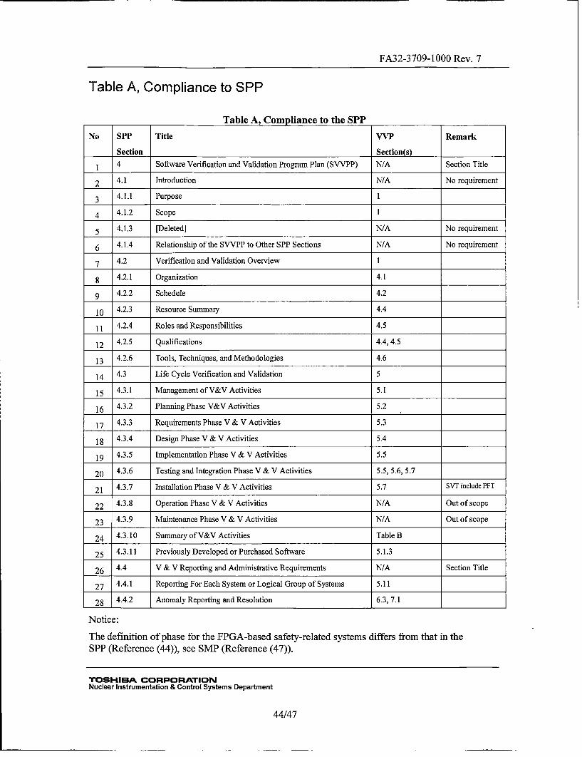
FA32-3709-1000 Rev. 7
Table A, Compliance to SPP
Table A, Compliance to the SPPNo SPP Title VVP Remark
Section Section(s)
1 4 Software Verification and Validation Program Plan (SVVPP) N/A Section Title
2 4.1 Introduction N/A No requirement
3 4.1.1 Purpose1
4 4.1.2 Scope1
5 4.3 [eee]N/A No requirement
6 4.1.4 Relationship of the SVVPP to Other SPP Sections N/A No requirement
7 4.2 Verification and Validation Overview1
8 4.2.1 Organization 4.1
9 4.2.2 Schedule 4.2
10 4.2.3 Resource Summary 4.4
11 4.2.4 Roles and Responsibilities 4.5
12 4.2.5 Qualifications 4.4, 4.5
13 4.2.6 Tools, Techniques, and Methodologies 4.6
14 4.3 Life Cycle Verification and Validation 5
15 4.3.1 Management of V&V Activities 5.1I
16 4.3.2 Planning Phase V&V Activities 5.2
17 4.3.3 Requirements Phase V & V Activities 5.3
18 4.. Design PhaseV & VActivities 5.4
19 4.3.5 Implementation Phase V & V Activities 5.5
20 4.3.6 Testing and Integration Phase V & V Activities 5.5, 5.6, 5.7
21 4.3.7 Installation Phase V & V Activities 5.7 SVT include PFT
22 4.3.8 Operation Phase V & V Activities N/A Out of scope
23 4.3.9 Maintenance Phase V & V Activities N/A Out of scope
24 4.3.10 Summary of V&V Activities Table B
25 4.3.11 Previously Developed or Purchased Software 5.1.3
26 4.4 V & V Reporting and Administrative Requirements N/A Section Title
27 4.4.1 Reporting For Each System or Logical Group of Systems 5.11
28 4.4.2 Anomaly Reporting and Resolution 6.3, 7.1
Notice:
The definition of phase for the FPGA-based safety-related systems differs from that in the
SPP (Reference (44)), see SMP (Reference (47)).
TOSHIBA CORPORATIONNuclear Instrumentation & Control Systems Department
44/47
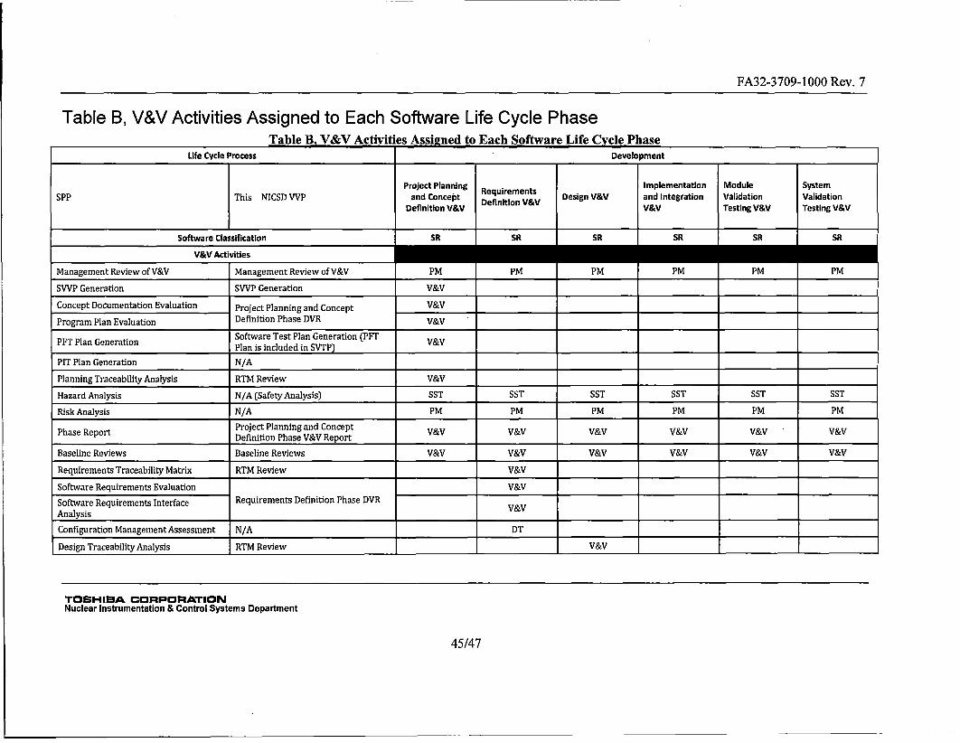
FA32-3709-1000 Rev. 7
Table B, V&V Activities Assigned to Each Software Life Cycle PhaseTable g. V&V Activities Assig~ned to Each Software Life Cycle Phase
Life Cycle Process Development________
Project Planning Implementation Module SystemDP hsNCDVV n ocp equirmnitso Design V&V and Integration Validation Validation
DeiiinVVDefinition V&V V&V Testing V&V Testing V&V
Software Classification SR SR SR SR SR SR
Management Review of V&V Management Review of V&V PM PM PM PM PM PMSVVP Generation SVVP Generation V&V
Concept Documentation Evaluation Project Planning and Concept V&VProgram Plan Evaluation Definition Phase DVR V&VPPT Plan Generation Software Test Plan Generation (PFT V&V
______________________________ Plan is included in SVTP)________ __ ______ ________ ________________
PIT Plan Generation N/A________ ________ ________ ________ _____ ___ ________
Planning Traceability Analysis RTM Review V&V________________
Hazard Analysis N/A (Safety Analysis) SST SST SST SST SST SSTRisk Analysis N/A PM PM PM PM PM PM
Phs eotProject Planning and ConceptV&V&VVV&VVVVPhs eotDefinition Phase V&V Report _______ ______________ ______________
Baseline Reviews Baseline Reviews V&V V&V V&V V&V V&V V&VRequirements Traceability Matrix RTM Review V&V_____________________
Software Requirements Evaluation V&V _______
Software Requirements Interface Requirements Definition Phase DVRAnalysis ____________________ __&______ _________V________ _________________
Configuration Management Assessment N/A ________ DT ______________________________
Design Traceability Analysis RTM Review V&V
TOSHIBA CORPORATIONNuclear Instrumentation & Control Systems Department
45/47
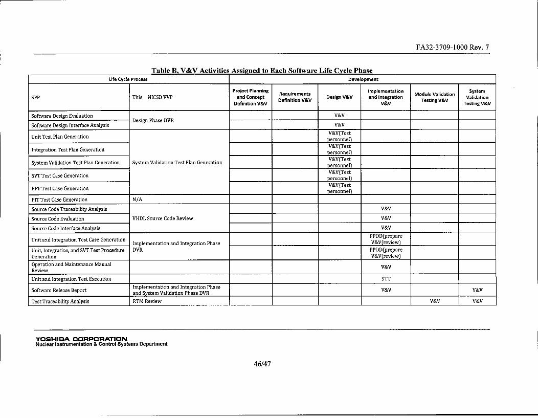
FA32-3709-1000 Rev. 7
K UflAt, flSg V t V attly RtIt,, flOORj~iAtO tt, flat,.. Lfl~RL VV flit, fliRt, t, V tAt, A flaOt,
Life Cycle Process Development
Project Planning Reqiements Implementation Module Validation System
SPP This NICSDVVP and Concept Definition V&V Design V&V and Integration TsigVV ValidationDefinition V&V eV&VTstn VV Testing V&V
Software Design Evaluation V&VDesign Phase DVR
Software Design Interface Analysis V&V
Unit Test Plan Generation Vp(erstne
Integration Test Plan Generation Vpersonel______________ ______________Tersone) _________________
System Validation Test Plan Generation System Validation Test Plan Generation Vpersonel
SVT Test Case Generation Vperstnel
PFT Test Case Generation V&(erstne
PIT Test Case Generation N/A _______ _______ _______________
Source Code Traceability Analysis V&V
Source Code Evaluation VHDL Source Code Review V&V
Source Code Interface Analysis V&V
UnitandIntgraionTestCas GeeraionPPDD(prepareUianInertoTetasGeeaon Implementation and Integration Phase _______________________ V&Vrreview)
Unit, Integration, and SYT Test Procedure DVR PPDD(prepareGeneration ______ ____________ V&V(review)Operation and Maintenance Manual V&VReview
Unit and Integration Test Execution STT
Softwar Releas ReportImplementation and Integration PhaseVVV&Software____Re __ease __Report___and System Validation Phase DVR V&V_______________________ V&V______________________
Test Traceability Analysis RTM Review V&V V&V
TOSHIBA CORPORATIONNuclear Instrumentation & Control Systems Department
46/4 7
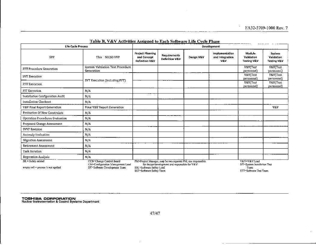
FA32-3709-1000 Rev. 7
Table B, V&V Activities Assigned to Each Software Life Cycle PhaseLife Cycle Process Development
Project Planning RImplementation Module SystemSPP This NICSD VVP enduonrptmefnitio s& Design V&V and Integration Validation Validation
adCnetDefinition V&V V&V Testing V&V Testing V&V
PFT Procedure Generation System Validation Test Procedure V&V(Test V&V(TestGeneration _________________ personnel) personnel)
SVT Execution V&V(Test V&V(TestSVT Execution (including PFT) personnel) personnel)
PF xcuinV&V(Test V&V(TestPFT__________Exec____ution______ ____________ personnel) personnel)
PIT Execution N/A
Installation Configuration Audit N/A _______ _______________
Installation Checkout N/A ________________________
V&V Final Report Generation Final V&V Report Generation V&V
Evaluation Of New Constraints N/A ________________
Operation Procedures Evaluation N/A
Proposed Change Assessment N/A
SVVP Revision N/A_________ _______
Anomaly Evaluation N/A_________
Migration Assessment N/A
Retirement Assessment N/A
Task Iteration N/A_________________________________ _______
Regression Analysis N/A
SR = Safety related CCB=Change Control Board PM=Project Manager, nmay be two separate PM, one responsible V&V=V&V LeadCM=Configuration Management Lead for design/development and responsible for V&V SIT=System Installation Test
empty cell = process is not applied DT=Software Development Team SSL=Softwsre Safety Lead TeamSST=Software Safety Team STT=Software Test Teamn
TOSHIBA CORPORATIONNuclear Instrumentation & Control Systems Department
47/4 7