Embed Size (px)
Citation preview

Gaining a Better Understanding of
FAA and Military Airport Pavement
Specifications
May 19th, 2015
Gary L. Mitchell P.E.
Vice President – Airports and Pavement Technology
American Concrete Pavement Association
Our Objective
Advance quality construction.
Educate:Contractor
Engineer
Inspector – Construction Manager
Awareness.
Minimize costly mistakes
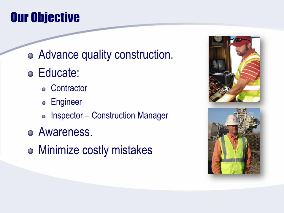
Not your typical highway pavement
Non channelized traffic
Heavy load
Heat
Mission based
No detours
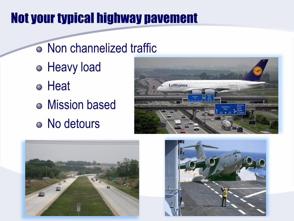
What Issues are Facing Airfields?
Inconsistent construction and inspection
Procurement/contracting limitations
High costs of:
Shutdowns
Aircraft
Increasing sensitivity to:
Operational readiness
Safety
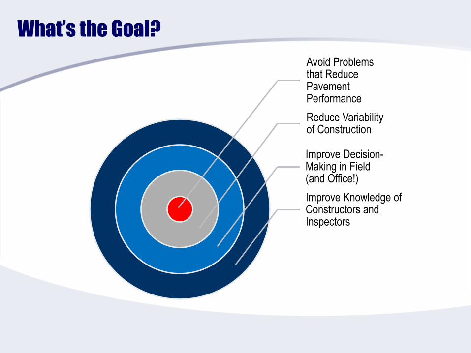
What’s the Goal?
Avoid Problems that Reduce Pavement Performance
Reduce Variability of Construction
Improve Decision-Making in Field(and Office!)
Improve Knowledge of Constructors and Inspectors
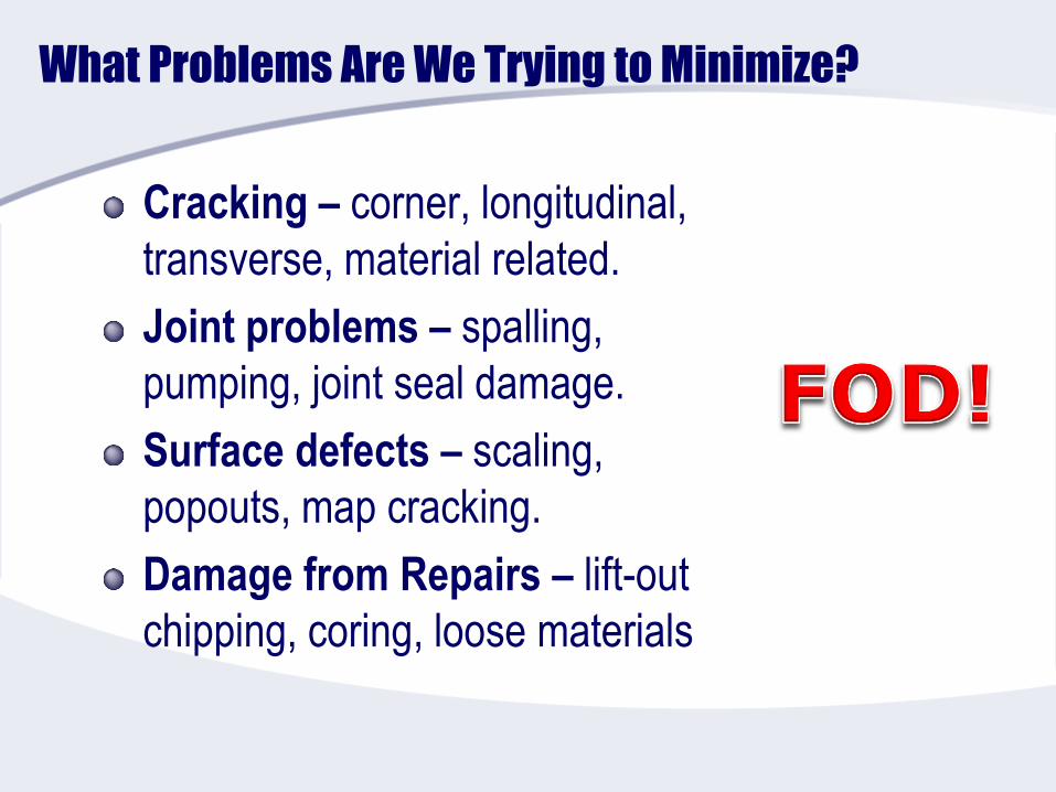
What Problems Are We Trying to Minimize?
Cracking – corner, longitudinal,
transverse, material related.
Joint problems – spalling,
pumping, joint seal damage.
Surface defects – scaling,
popouts, map cracking.
Damage from Repairs – lift-out
chipping, coring, loose materials
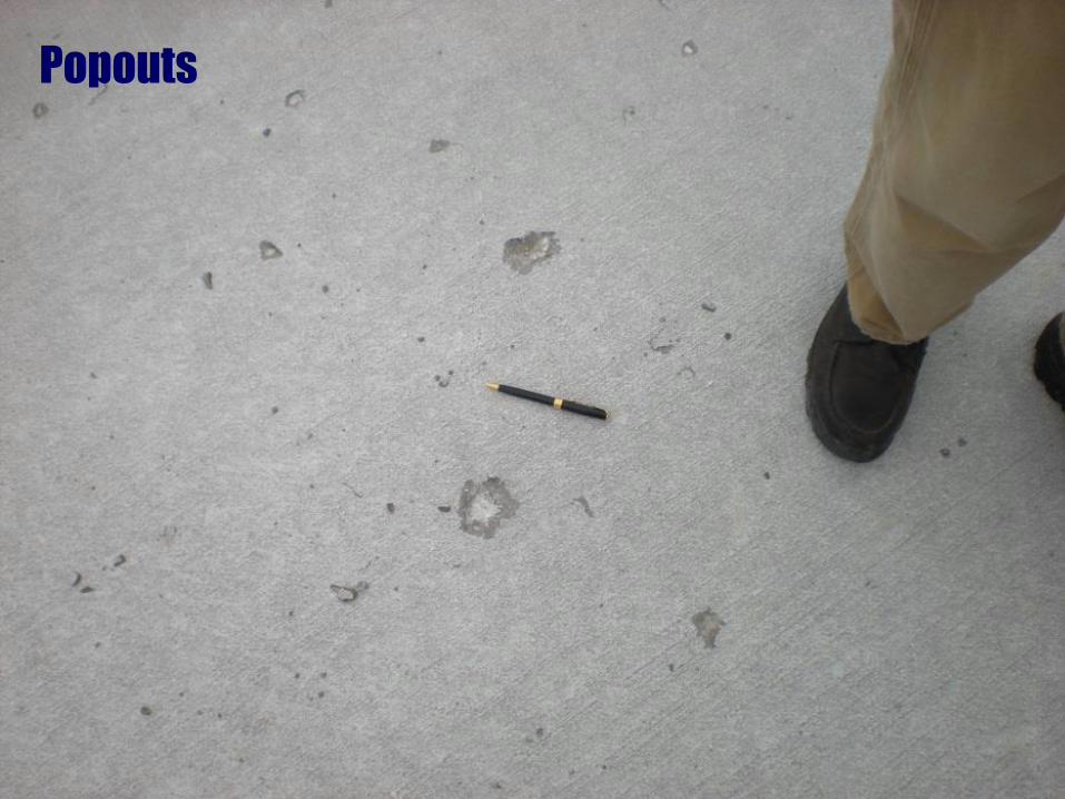
Popouts
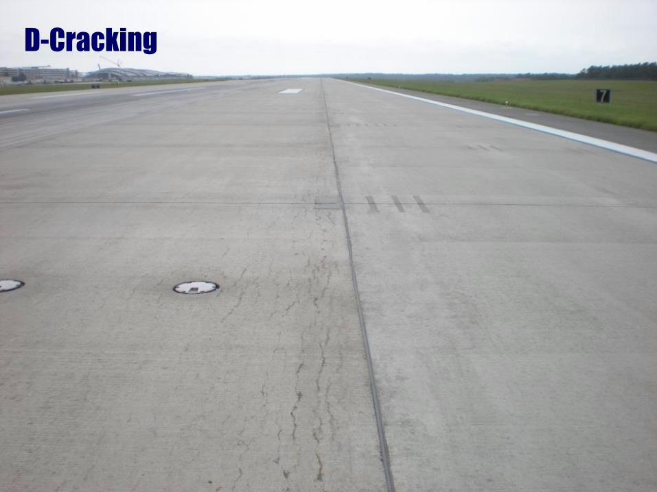
D-Cracking
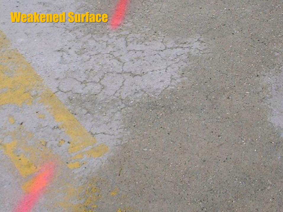
Weakened Surface
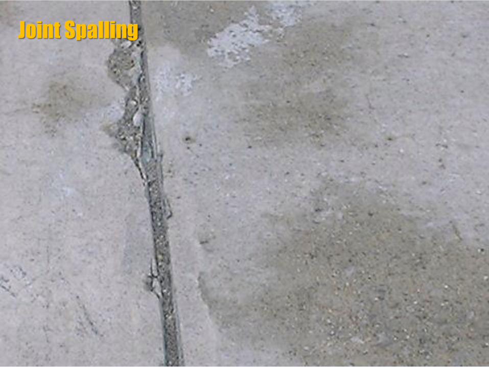
Joint Spalling
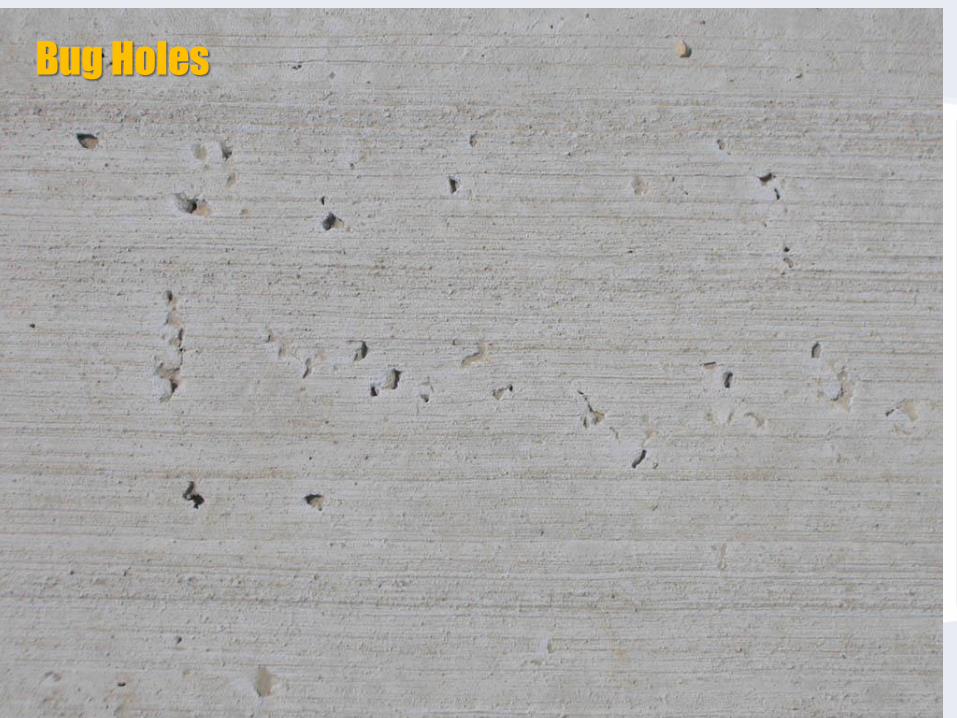
Bug Holes

What Minimizes the Risk of Distress?
Sound Design Principles
Thickness Design
Foundation Support
Joint Layout
Concrete Mixture Design

What Minimizes the Risk of Distress?
Sound Construction
Principles
Stockpiling & Mixing
Placing & Consolidating
Finishing & Curing
Jointing & Sealing
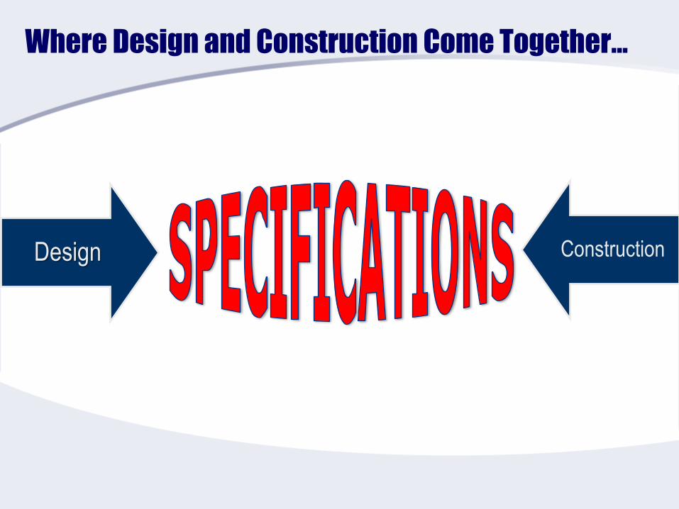
Where Design and Construction Come Together…
Design Construction
The Conundrum – Quality Cannot be Specified!
Specifications don’t always say what they mean
Current specifications rely on tests that are only
surrogates for quality
Strength
Thickness
Air content
Smoothness
The construction team needs to understand the
balances among these sometimes competing factors

Conformance to the Specifications
Despite the challenge… assessing quality in
construction equates to how well construction
conforms to specification requirements.
So it is vital that requirements are:
Reasonable (target the average bidder)
Meaningful (not arbitrary)
Measurable (by testing)
Well defined (account for test variability)
Hold true (do not conflict w/ other requirements)

Concrete Pavement for Heavy Duty Airfields
High quality, durable concrete – no FODSame thing right?
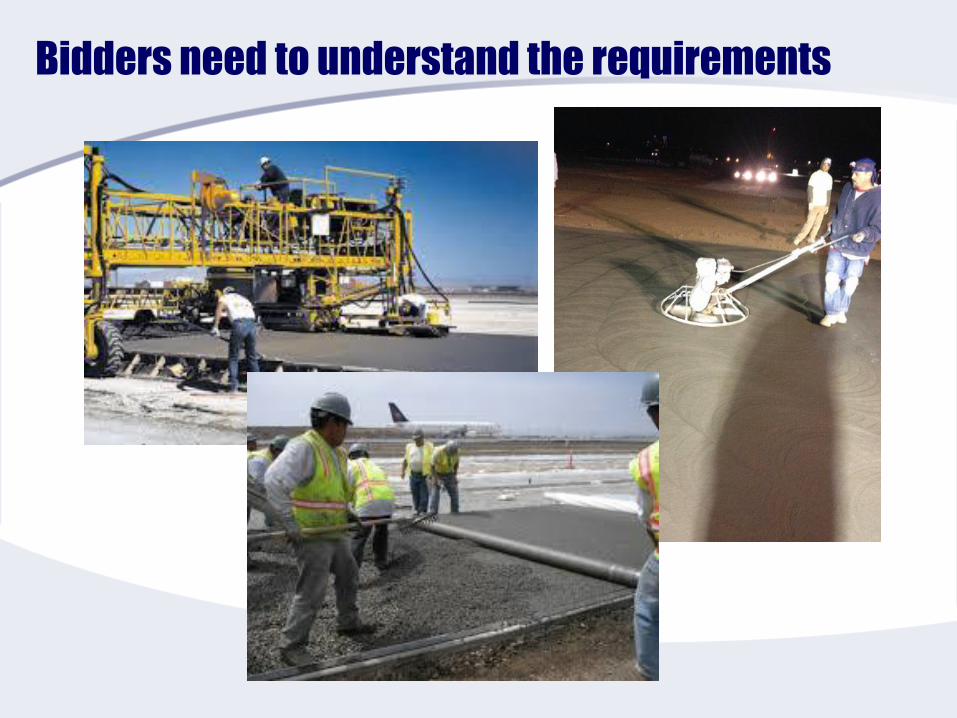
Bidders need to understand the requirements
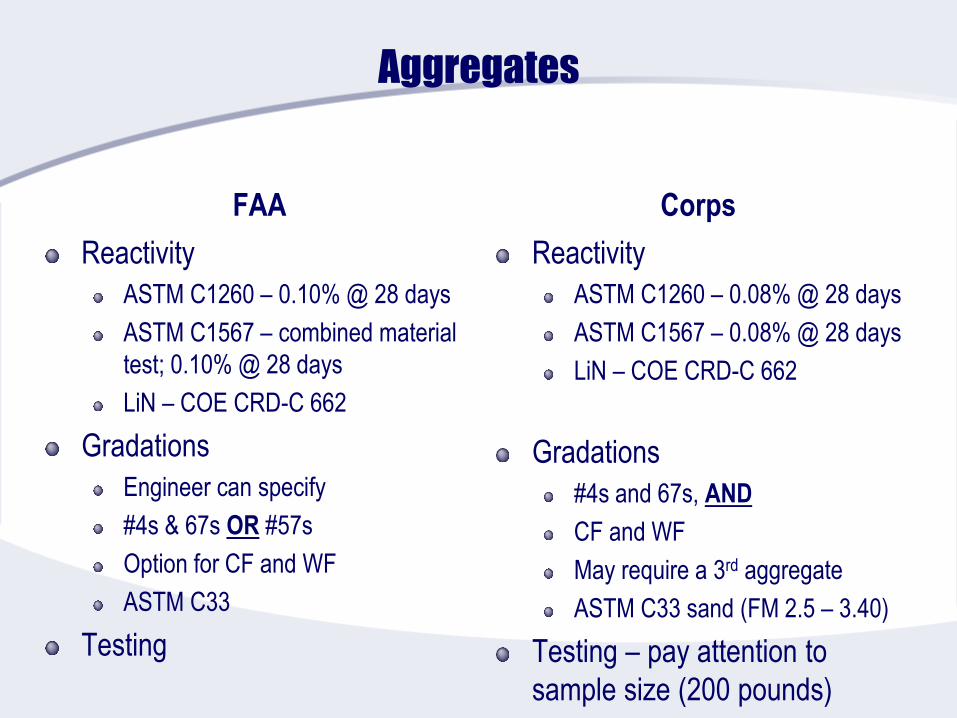
Aggregates
FAA
Reactivity
ASTM C1260 – 0.10% @ 28 days
ASTM C1567 – combined material
test; 0.10% @ 28 days
LiN – COE CRD-C 662
Gradations
Engineer can specify
#4s & 67s OR #57s
Option for CF and WF
ASTM C33
Testing
Corps
Reactivity
ASTM C1260 – 0.08% @ 28 days
ASTM C1567 – 0.08% @ 28 days
LiN – COE CRD-C 662
Gradations
#4s and 67s, AND
CF and WF
May require a 3rd aggregate
ASTM C33 sand (FM 2.5 – 3.40)
Testing – pay attention to
sample size (200 pounds)
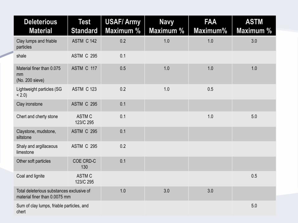
Deleterious
Material
Test
Standard
USAF/ Army
Maximum %
Navy
Maximum %
FAA
Maximum%
ASTM
Maximum %
Clay lumps and friable
particles
ASTM C 142 0.2 1.0 1.0 3.0
shale ASTM C 295 0.1
Material finer than 0.075
mm
(No. 200 sieve)
ASTM C 117 0.5 1.0 1.0 1.0
Lightweight particles (SG
< 2.0)
ASTM C 123 0.2 1.0 0.5
Clay ironstone ASTM C 295 0.1
Chert and cherty stone ASTM C
123/C 295
0.1 1.0 5.0
Claystone, mudstone,
siltstone
ASTM C 295 0.1
Shaly and argillaceous
limestone
ASTM C 295 0.2
Other soft particles COE CRD-C
130
0.1
Coal and lignite ASTM C
123/C 295
0.5
Total deleterious substances exclusive of
material finer than 0.0075 mm
1.0 3.0 3.0
Sum of clay lumps, friable particles, and
chert
5.0
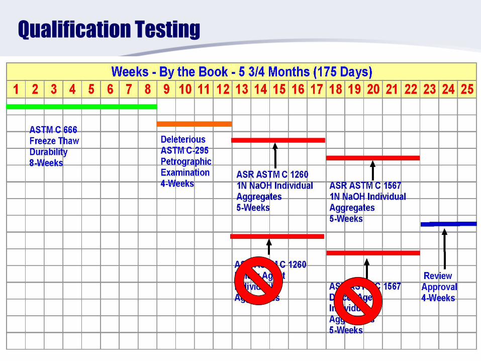
Qualification Testing
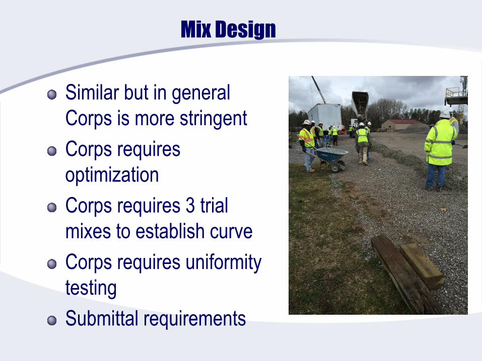
Mix Design
Similar but in general
Corps is more stringent
Corps requires
optimization
Corps requires 3 trial
mixes to establish curve
Corps requires uniformity
testing
Submittal requirements

Concrete Mixture Submittals
FAA
The submitted mix design shall be stamped or sealed by the responsible professional Engineer of the
laboratory and shall include the following items as a minimum:
a. Coarse, fine, and combined aggregate gradations and plots including fineness modulus of the fine
aggregate.
b. Reactivity Test Results.
c. Coarse aggregate quality test results, including deleterious materials.
d. Fine aggregate quality test results, including deleterious materials.
e. Mill certificates for cement and supplemental cementitious materials.
f. Certified test results for all admixtures, including Lithium Nitrate if applicable.
g. Specified flexural strength, slump, and air content.
h. Recommended proportions/volumes for proposed mixture and trial water-cementitious materials
ratio, including actual slump and air content.
i. Flexural and compressive strength summaries and plots, including all individual beam and cylinder
breaks.
j. Correlation ratios for acceptance testing and Contractor Quality Control testing, when applicable.
k. Historical record of test results documenting production standard deviation, when applicable.
Corps
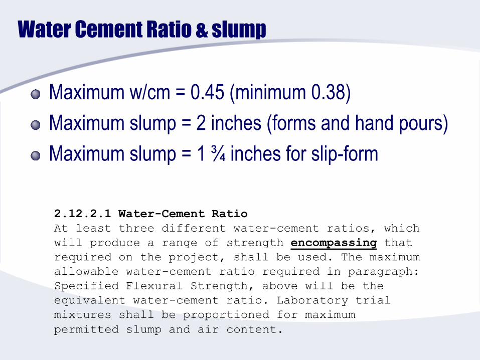
Water Cement Ratio & slump
Maximum w/cm = 0.45 (minimum 0.38)
Maximum slump = 2 inches (forms and hand pours)
Maximum slump = 1 ¾ inches for slip-form
2.12.2.1 Water-Cement Ratio
At least three different water-cement ratios, which
will produce a range of strength encompassing that
required on the project, shall be used. The maximum
allowable water-cement ratio required in paragraph:
Specified Flexural Strength, above will be the
equivalent water-cement ratio. Laboratory trial
mixtures shall be proportioned for maximum
permitted slump and air content.

Equipment
* * * * * * * * * * * * * * * * * * * * * * * * * * * * * * * * * * * * * * * * * * * * * * * * * * * * * * * * * * * * *
The Engineer may specify the use of a central plant mixer if deemed necessary for a
particular project.
* * * * * * * * * * * * * * * * * * * * * * * * * * * * * * * * * * * * * * * * * * * * * * * * * * * * * * * * * * * * *
c. Finishing Equipment. The standard method of constructing concrete pavements on FAA projects shall be with an approved slip-form
paving equipment designed to spread, consolidate, screed, and float-finish the freshly placed concrete in one complete pass of the
machine so a dense and homogeneous pavement is achieved with a minimum of hand finishing. The paver-finisher shall be a heavy duty,
self-propelled machine designed specifically for paving and finishing high quality concrete pavements. It shall weigh at least 2200 lbs. per
foot of paving lane width and powered by an engine having at least 6.0 horsepower per foot of lane width.
On projects requiring less than 500 square yards of cement concrete pavement or requiring individual placement areas of less than 500
square yards, or irregular areas at locations inaccessible to slip-form paving equipment, cement concrete pavement may be placed with
approved placement and finishing equipment utilizing stationary side forms. Hand screeding and float finishing may only be utilized on
small irregular areas as allowed by the Engineer.
d. Vibrators. Vibrator shall be the internal type. Operating frequency for internal vibrators shall be between 8,000 and 12,000 vibrations
per minute. Average amplitude for internal vibrators shall be 0.025-0.05 inches (0.06-0.13 cm).
The number, spacing, and frequency shall be as necessary to provide a dense and homogeneous pavement and meet the
recommendations of ACI 309, Guide for Consolidation of Concrete. Adequate power to operate all vibrators shall be available on the
paver. The vibrators shall be automatically controlled so that they shall be stopped as forward motion ceases. The contractor shall
provide an electronic or mechanical means to monitor vibrator status. The checks on vibrator status shall occur a minimum of two times
per day or when requested by the Engineer.
Hand held vibrators may be used in irregular areas only, but shall meet the recommendations of ACI 309, Guide for Consolidation of
Concrete.
Paragraph 501-4.1 Equipment32 13 11: 2.10.5 Paver-Finisher

P-501: 4-11 Finishing
b. Machine finishing with fixed forms. The machine shall be
designed to straddle the forms and shall be operated to screed and
consolidate the concrete. Machines that cause displacement of the
forms shall be replaced. The machine shall make only one pass over
each area of pavement. If the equipment and procedures do not
produce a surface of uniform texture, true to grade, in one pass, the
operation shall be immediately stopped and the equipment, mixture,
and procedures adjusted as necessary.
c. Other types of finishing equipment. Clary screeds, other
rotating tube floats, or bridge deck finishers are not allowed on
mainline paving, but may be allowed on irregular or odd-shaped
slabs, and near buildings or trench drains, subject to the Engineer’s
approval.
Bridge deck finishers shall have a minimum operating weight of
7500 pounds (3400 kg) and shall have a transversely operating
carriage containing a knock-down auger and a minimum of two
immersion vibrators. Vibrating screeds or pans shall be used only for
isolated slabs where hand finishing is permitted as specified, and only
where specifically approved.
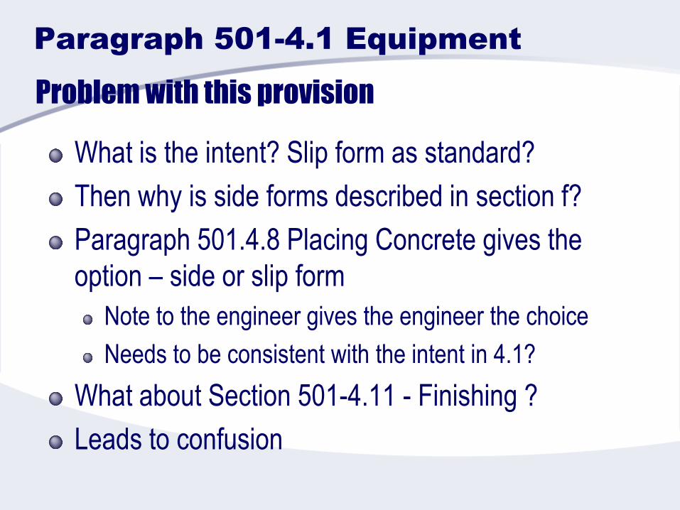
Problem with this provision
What is the intent? Slip form as standard?
Then why is side forms described in section f?
Paragraph 501.4.8 Placing Concrete gives the
option – side or slip form
Note to the engineer gives the engineer the choice
Needs to be consistent with the intent in 4.1?
What about Section 501-4.11 - Finishing ?
Leads to confusion
Paragraph 501-4.1 Equipment
Test Section
P-501 does not require a test section
32 13 11 Section 1.5.6 – Test Section
400 feet pilot lane
400 feet fill in lane
Must meet all specification requirements to leave in
place
Must use equipment and procedure subsequently
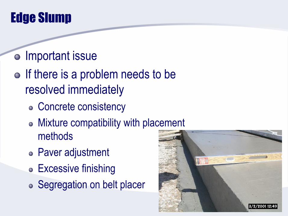
Edge Slump
Important issue
If there is a problem needs to be
resolved immediately
Concrete consistency
Mixture compatibility with placement
methods
Paver adjustment
Excessive finishing
Segregation on belt placer

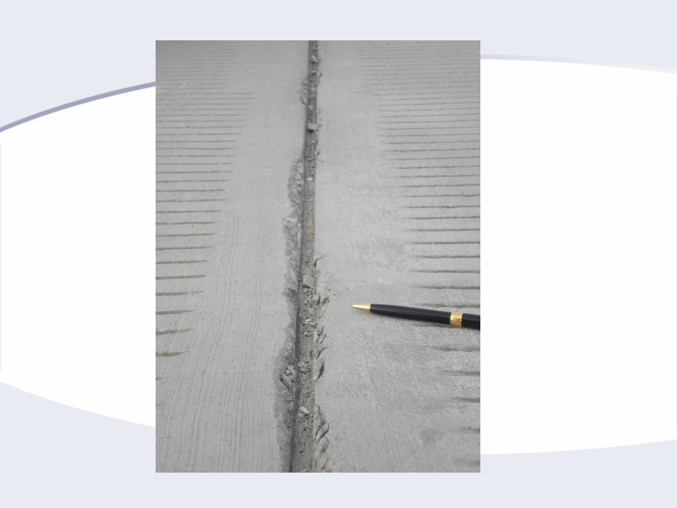
Edge Slump
Big deal for airports
Ponding water in the joints—joint deterioration
Often leads to spalling because of working the
edges
Indication something is wrong with the mixture
< 15% of free edge with ¼ inch; none > 3/8 inch
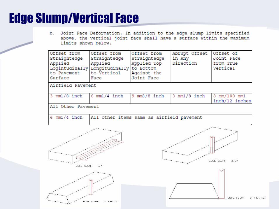
Edge Slump/Vertical Face
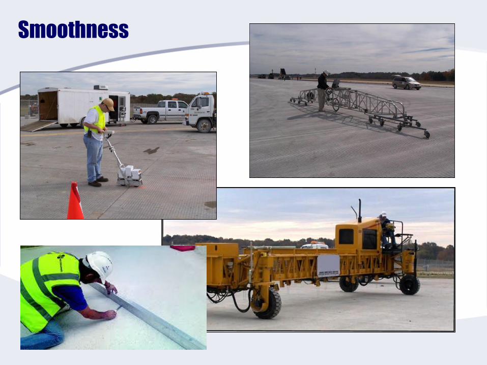
Smoothness
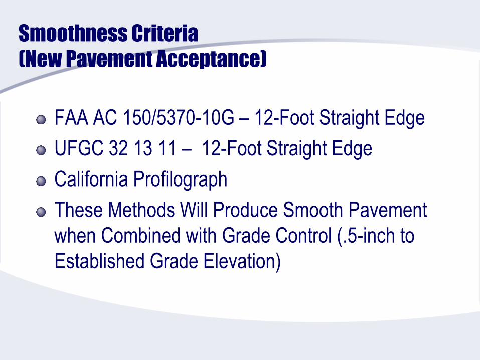
Smoothness Criteria
(New Pavement Acceptance)
FAA AC 150/5370-10G – 12-Foot Straight Edge
UFGC 32 13 11 – 12-Foot Straight Edge
California Profilograph
These Methods Will Produce Smooth Pavement
when Combined with Grade Control (.5-inch to
Established Grade Elevation)
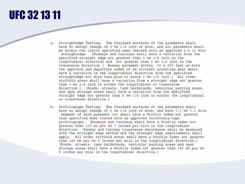
UFC 32 13 11
FAA P-501
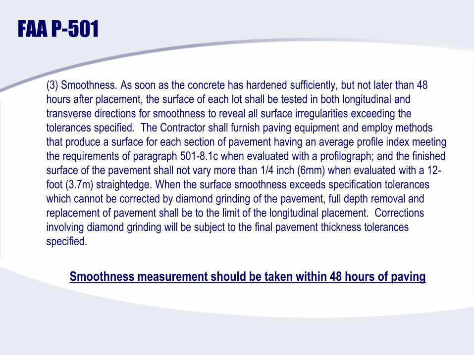
(3) Smoothness. As soon as the concrete has hardened sufficiently, but not later than 48
hours after placement, the surface of each lot shall be tested in both longitudinal and
transverse directions for smoothness to reveal all surface irregularities exceeding the
tolerances specified. The Contractor shall furnish paving equipment and employ methods
that produce a surface for each section of pavement having an average profile index meeting
the requirements of paragraph 501-8.1c when evaluated with a profilograph; and the finished
surface of the pavement shall not vary more than 1/4 inch (6mm) when evaluated with a 12-
foot (3.7m) straightedge. When the surface smoothness exceeds specification tolerances
which cannot be corrected by diamond grinding of the pavement, full depth removal and
replacement of pavement shall be to the limit of the longitudinal placement. Corrections
involving diamond grinding will be subject to the final pavement thickness tolerances
specified.
Smoothness measurement should be taken within 48 hours of paving
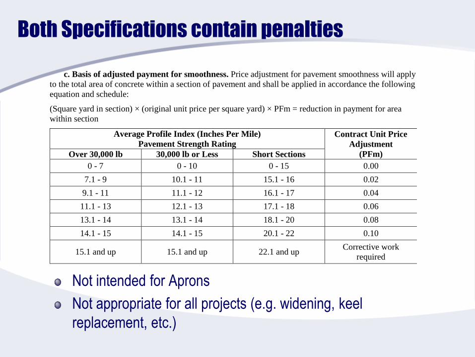
Both Specifications contain penalties
Not intended for Aprons
Not appropriate for all projects (e.g. widening, keel
replacement, etc.)
c. Basis of adjusted payment for smoothness. Price adjustment for pavement smoothness will apply
to the total area of concrete within a section of pavement and shall be applied in accordance the following
equation and schedule:
(Square yard in section) × (original unit price per square yard) × PFm = reduction in payment for area
within section
Average Profile Index (Inches Per Mile)
Pavement Strength Rating
Contract Unit Price
Adjustment
(PFm) Over 30,000 lb 30,000 lb or Less Short Sections
0 - 7 0 - 10 0 - 15 0.00
7.1 - 9 10.1 - 11 15.1 - 16 0.02
9.1 - 11 11.1 - 12 16.1 - 17 0.04
11.1 - 13 12.1 - 13 17.1 - 18 0.06
13.1 - 14 13.1 - 14 18.1 - 20 0.08
14.1 - 15 14.1 - 15 20.1 - 22 0.10
15.1 and up 15.1 and up 22.1 and up Corrective work
required
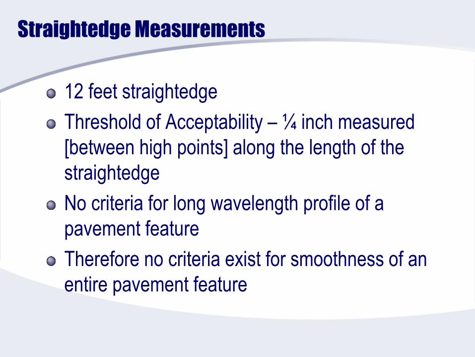
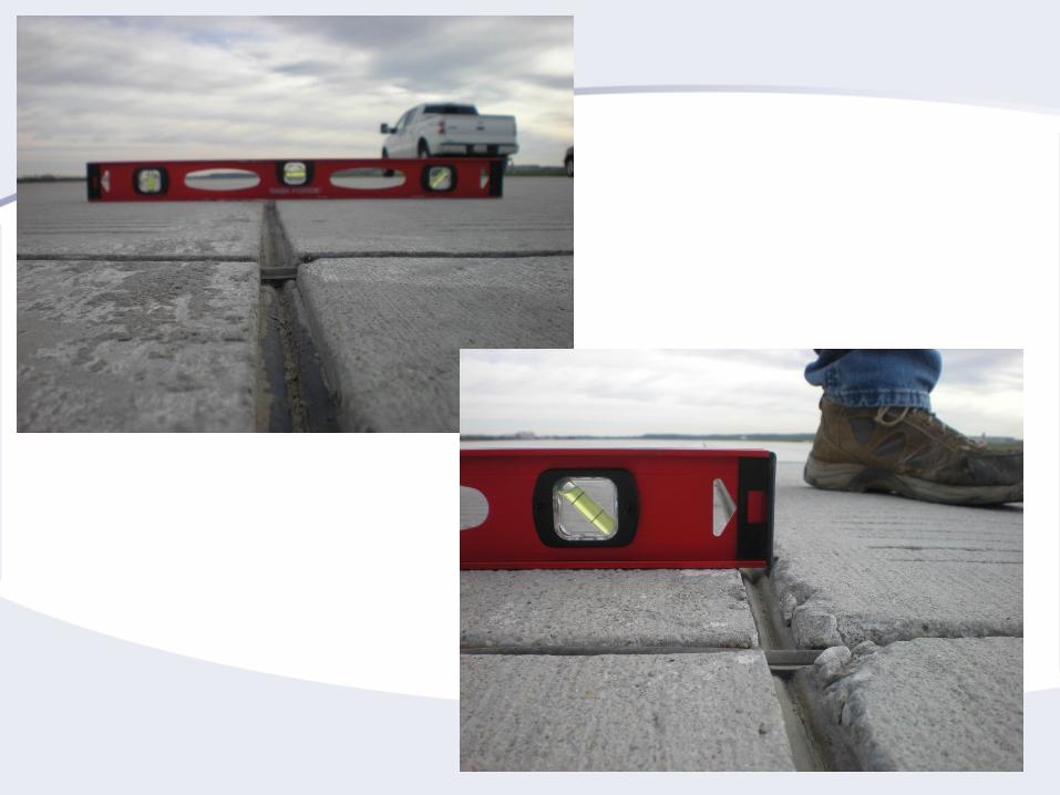
Straightedge Measurements
12 feet straightedge
Threshold of Acceptability – ¼ inch measured
[between high points] along the length of the
straightedge
No criteria for long wavelength profile of a
pavement feature
Therefore no criteria exist for smoothness of an
entire pavement feature
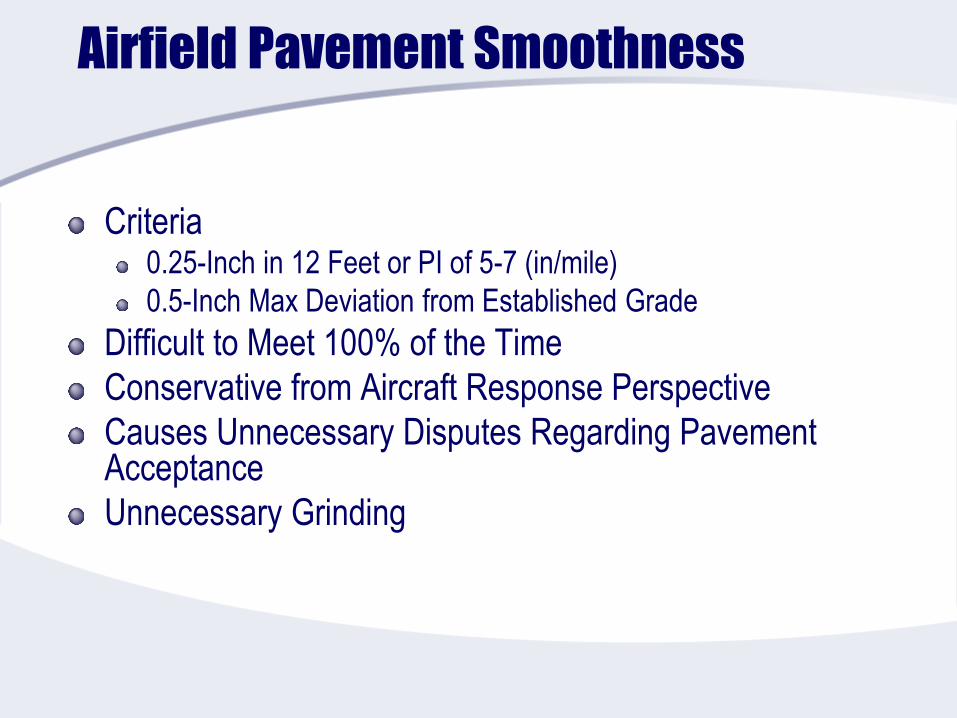
Airfield Pavement Smoothness
Criteria0.25-Inch in 12 Feet or PI of 5-7 (in/mile)
0.5-Inch Max Deviation from Established Grade
Difficult to Meet 100% of the Time
Conservative from Aircraft Response Perspective
Causes Unnecessary Disputes Regarding Pavement Acceptance
Unnecessary Grinding
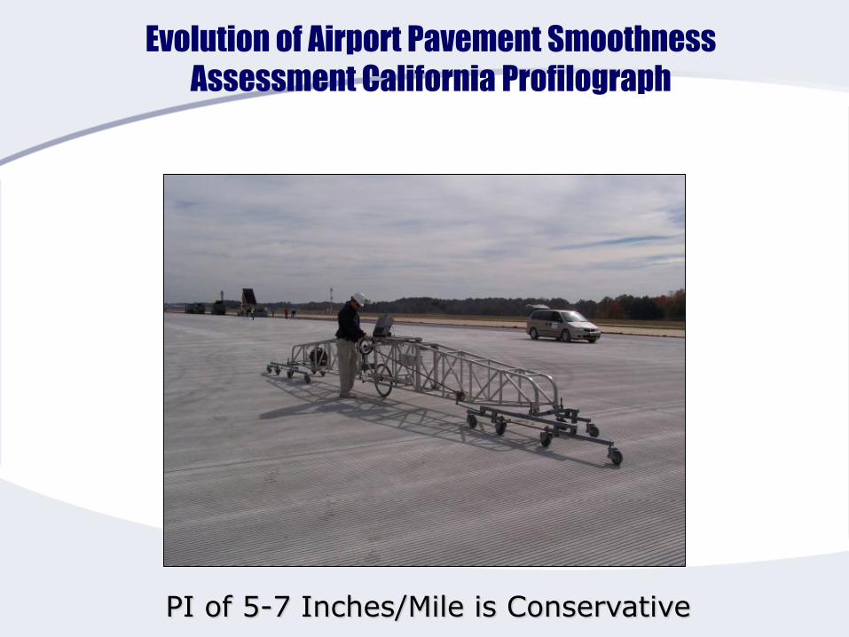
Evolution of Airport Pavement Smoothness
Assessment California Profilograph
PI of 5-7 Inches/Mile is Conservative
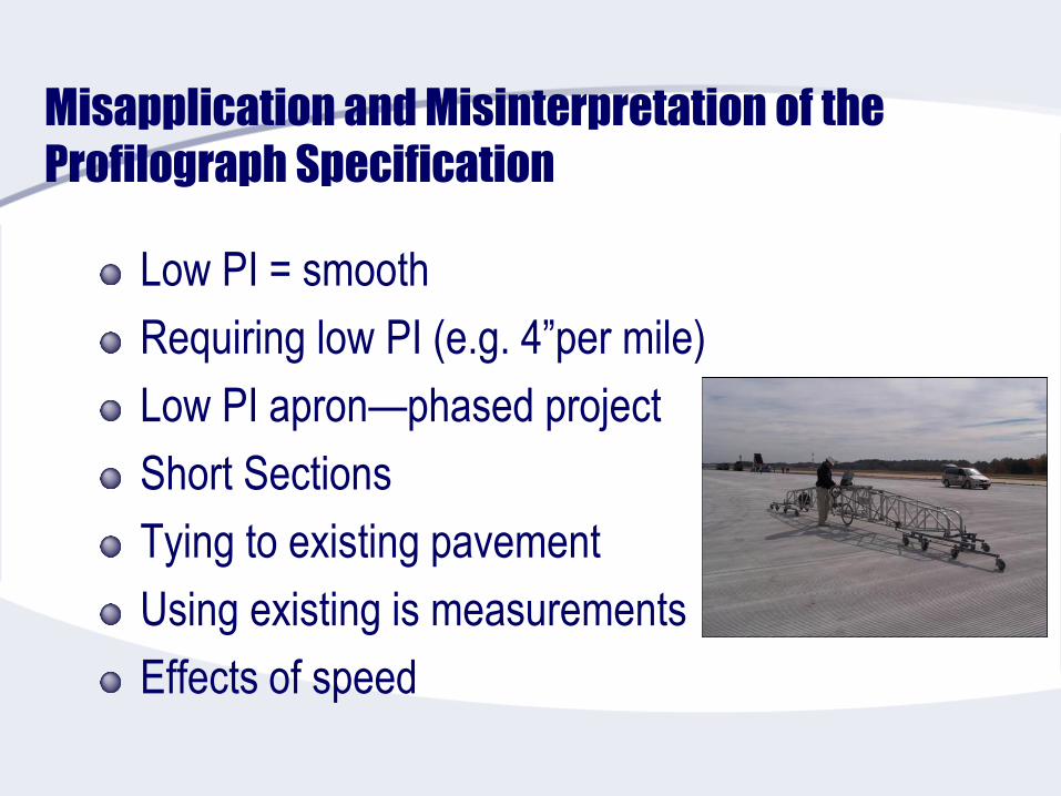
Misapplication and Misinterpretation of the
Profilograph Specification
Low PI = smooth
Requiring low PI (e.g. 4”per mile)
Low PI apron—phased project
Short Sections
Tying to existing pavement
Using existing is measurements
Effects of speed

What About Grade Control?
(4) Grade. An evaluation of the surface grade shall be made by the Engineer for compliance to the
tolerances contained below. The finish grade will be determined by running levels at intervals of 50 feet (15
m) or less longitudinally and all breaks in grade transversely (not to exceed 50 feet (15 m)) to determine the
elevation of the completed pavement. The Contractor shall pay the costs of surveying the level runs, and this
work shall be performed by a licensed surveyor. The documentation, stamped and signed by a licensed
surveyor, shall be provided by the Contractor to the Engineer.
(a) Lateral deviation. Lateral deviation from established alignment of the pavement edge shall
not exceed ±0.10 feet (3 mm) in any lane.
(b) Vertical deviation. Vertical deviation from established grade shall not exceed ±0.04 feet
(12 mm) at any point.
Primary Purpose of Smoothness Testing?
Smoothness testing indicated in the above paragraphs except
paragraph (iii) shall be performed within 48 hours of placement of
material. Smoothness texting indicated in paragraph (iii) shall be
performed within 48 hours final paving completion. The primary
purpose of smoothness testing is to identify areas that may be
prone to ponding of water which could lead to hydroplaning of
aircraft. If the contractor’s machines and/or methods are producing
significant areas that need corrective actions then production should
be stopped until corrective measures can be implemented. If
corrective measures are not implemented and when directed by the
Engineer, production shall be stopped until corrective measures can
be implemented.
Protect the Aircraft
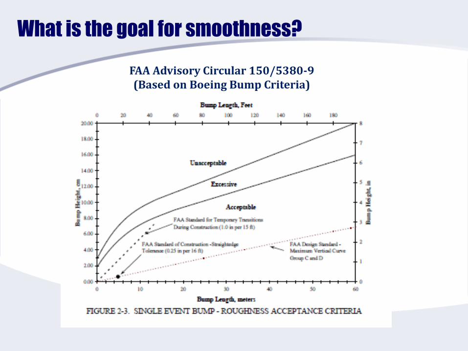
What is the goal for smoothness?
FAA Advisory Circular 150/5380-9(Based on Boeing Bump Criteria)
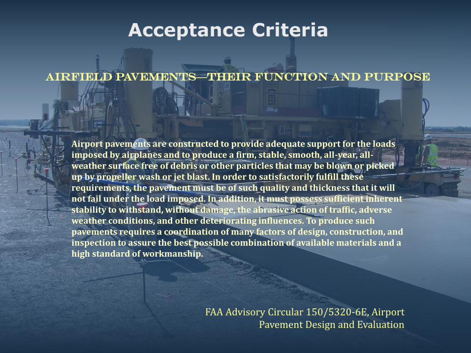
Airfield pavements—Their Function and purpose
Airport pavements are constructed to provide adequate support for the loads imposed by airplanes and to produce a firm, stable, smooth, all-year, all-weather surface free of debris or other particles that may be blown or picked up by propeller wash or jet blast. In order to satisfactorily fulfill these requirements, the pavement must be of such quality and thickness that it will not fail under the load imposed. In addition, it must possess sufficient inherent stability to withstand, without damage, the abrasive action of traffic, adverse weather conditions, and other deteriorating influences. To produce such pavements requires a coordination of many factors of design, construction, and inspection to assure the best possible combination of available materials and a high standard of workmanship.
FAA Advisory Circular 150/5320-6E, Airport Pavement Design and Evaluation
Acceptance Criteria
So…
What is the Designer’s or (Engineer of Record)
Role
Creates Detailed and Executable plans and specifications (to meet owners needs)
Reviews Shop Drawings and Submittals
Ensures Compliance with Specs
Manages Liability
Makes a little profit

And…
What is the Contractor’s Role
Good Craftsmanship
Needs Concrete that Satisfies Owner
Engineer (Technical)
Owner (Appearance????)
Crew (Place and Finish)
Profitable

Generally, Everyone intends to do quality work
Material Acceptance, testing and Quality Control
Suppose the contractor meets QC requirements
Suppose all materials meet testing requirements
Imperfect materials
Imperfect process
Imperfect people
Should we always expect perfect?
Things can still go wrong!
Do we always – remove and replace?
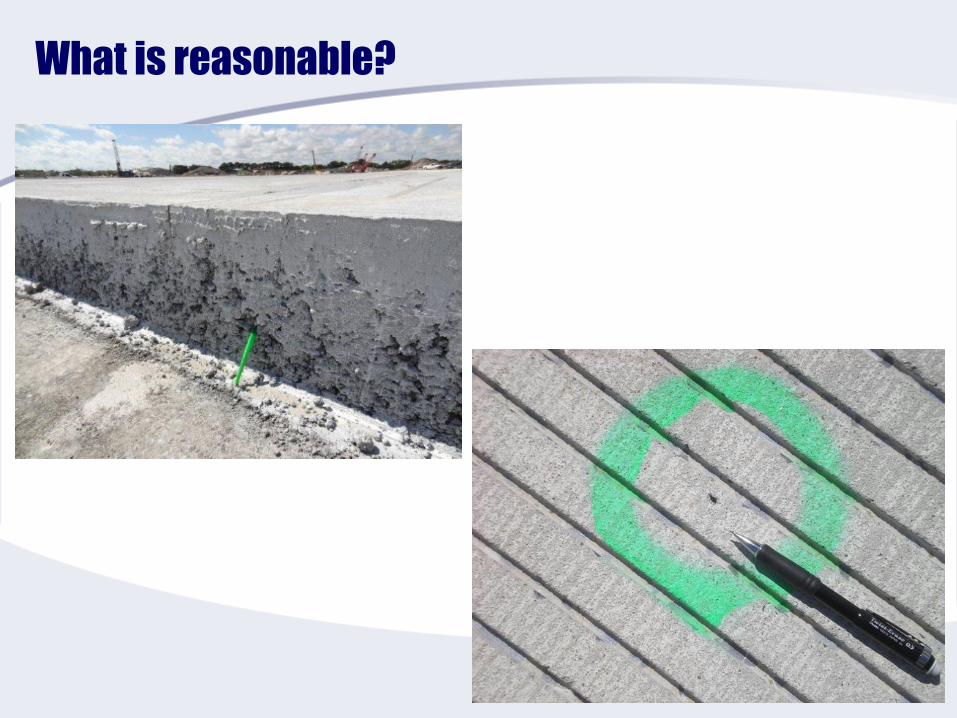
What is reasonable?

Let’s look at the Specifications
Pay ItemsStrength
Thickness
Suspension of WorkSlump
Air
Dowel Bar AlignmentHorizontal
Vertical
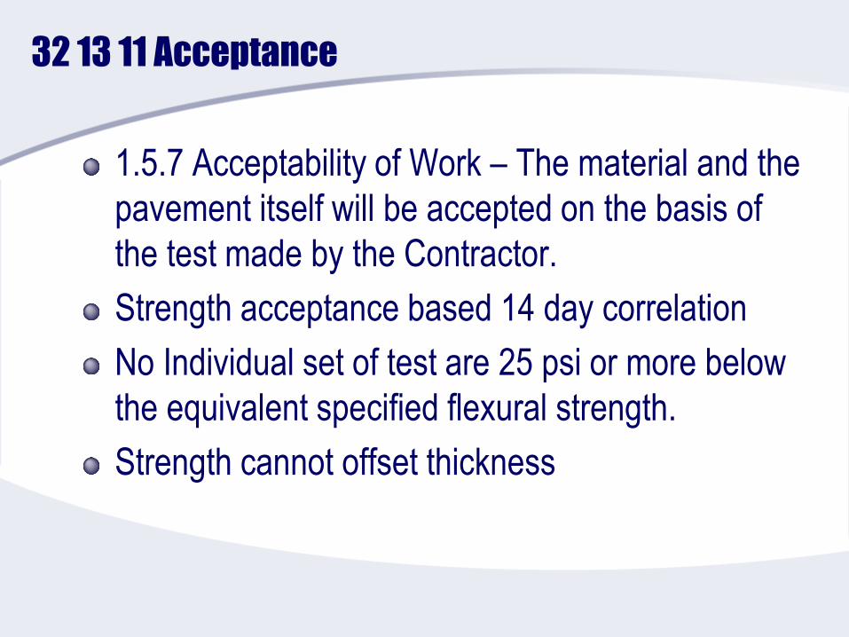
32 13 11 Acceptance
1.5.7 Acceptability of Work – The material and the
pavement itself will be accepted on the basis of
the test made by the Contractor.
Strength acceptance based 14 day correlation
No Individual set of test are 25 psi or more below
the equivalent specified flexural strength.
Strength cannot offset thickness
FAA P-501-5.2 Acceptance criteria.
Flexural strength
Thickness
Smoothness
Grade
Edge slump
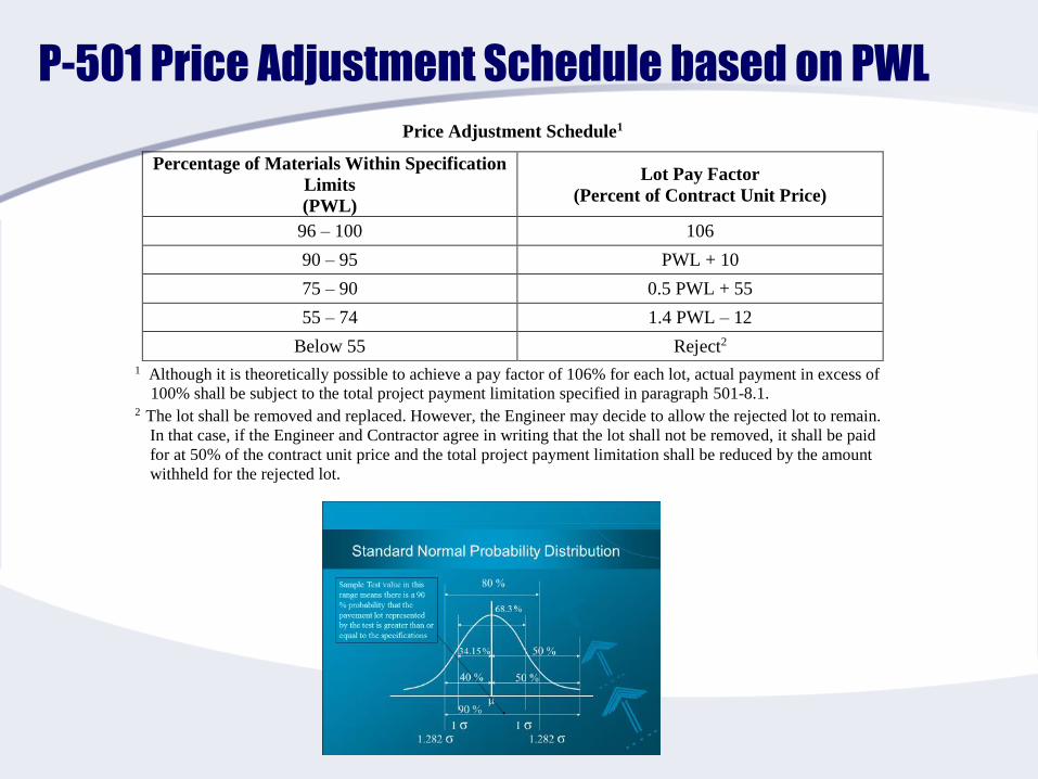
P-501 Price Adjustment Schedule based on PWL
Price Adjustment Schedule1
Percentage of Materials Within Specification
Limits
(PWL)
Lot Pay Factor
(Percent of Contract Unit Price)
96 – 100 106
90 – 95 PWL + 10
75 – 90 0.5 PWL + 55
55 – 74 1.4 PWL – 12
Below 55 Reject2
1 Although it is theoretically possible to achieve a pay factor of 106% for each lot, actual payment in excess of
100% shall be subject to the total project payment limitation specified in paragraph 501-8.1. 2 The lot shall be removed and replaced. However, the Engineer may decide to allow the rejected lot to remain.
In that case, if the Engineer and Contractor agree in writing that the lot shall not be removed, it shall be paid
for at 50% of the contract unit price and the total project payment limitation shall be reduced by the amount
withheld for the rejected lot.
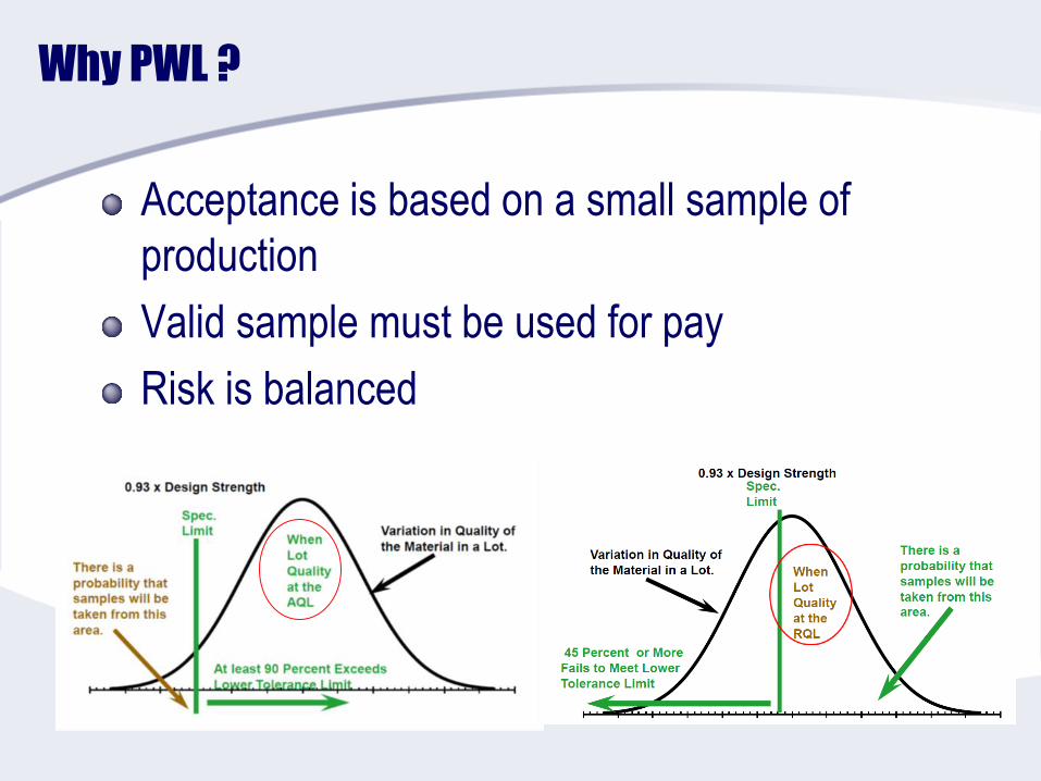
Why PWL ?
Acceptance is based on a small sample of
production
Valid sample must be used for pay
Risk is balanced

FAA General Provision
Section 50-02 – Conformity with plans and
specifications
Opens the door for “engineer’s opinion” on contract
enforcement
Consult with FAA on “reasonably close conformity”
Doesn’t mean waive the contractor’s responsibility to
meet the requirements of the contract, plans, & specs
“reasonably close conformity” is not explicitly defined
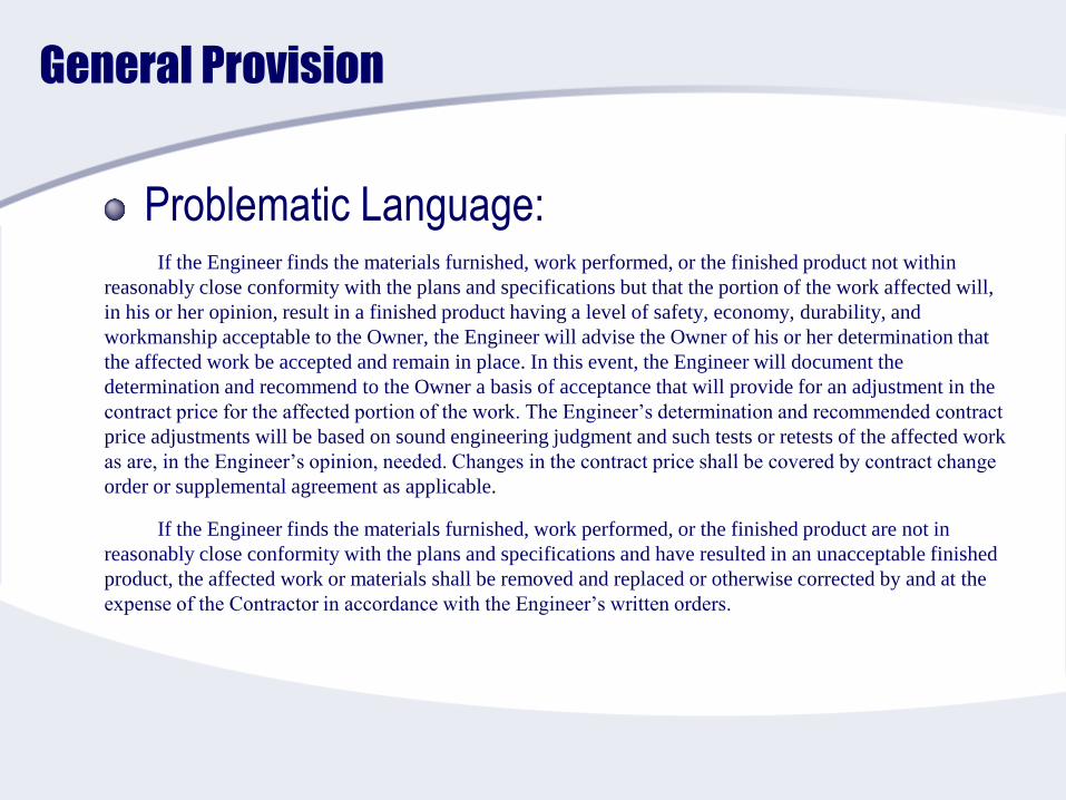
General Provision
Problematic Language:If the Engineer finds the materials furnished, work performed, or the finished product not within
reasonably close conformity with the plans and specifications but that the portion of the work affected will,
in his or her opinion, result in a finished product having a level of safety, economy, durability, and
workmanship acceptable to the Owner, the Engineer will advise the Owner of his or her determination that
the affected work be accepted and remain in place. In this event, the Engineer will document the
determination and recommend to the Owner a basis of acceptance that will provide for an adjustment in the
contract price for the affected portion of the work. The Engineer’s determination and recommended contract
price adjustments will be based on sound engineering judgment and such tests or retests of the affected work
as are, in the Engineer’s opinion, needed. Changes in the contract price shall be covered by contract change
order or supplemental agreement as applicable.
If the Engineer finds the materials furnished, work performed, or the finished product are not in
reasonably close conformity with the plans and specifications and have resulted in an unacceptable finished
product, the affected work or materials shall be removed and replaced or otherwise corrected by and at the
expense of the Contractor in accordance with the Engineer’s written orders.
Pavement Repair during construction(32 13 11)
If I cracks it comes out – in general
Cracks < 2” may be repaired
Up to 15% spalled edge can be repaired
Repairs are prescriptive
3.9 REPAIR, REMOVAL AND REPLACEMENT OF NEWLY CONSTRUCTED SLABS
3.9.1 General Criteria
New pavement slabs that are broken, have spalled edges, or contain cracks
shall be removed and replaced or repaired, as specified at no cost to the
Government. Removal of partial slabs is not permitted. Not more than 15.0
percent of each slab's longitudinal joint edge shall be spalled. Prior to
fill-in lane placement, pilot lane slabs with spalls exceeding this
quantity, regardless of spall size, shall be sawn full depth to remove the
spalled face. All other slabs shall be removed, as directed. The
Contracting Officer will determine whether cracks extend full depth of the
pavement and may require cores to be drilled on the crack to determine
depth of cracking. Such cores shall be at least 150 mm 6 inch diameter,
and shall be drilled and backfilled with an approved non-shrink concrete.
Perform drilling of cores and refilling holes at no expense to the
Government.
Pavement Repair during construction(32 13 11)
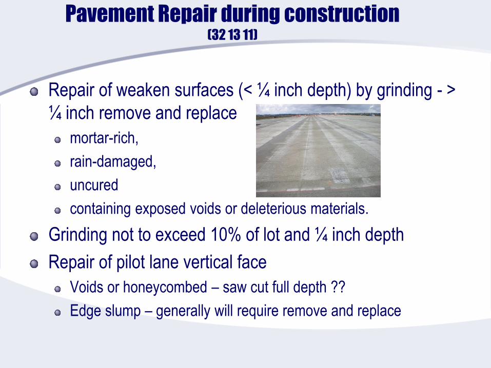
Repair of weaken surfaces (< ¼ inch depth) by grinding - >
¼ inch remove and replace
mortar-rich,
rain-damaged,
uncured
containing exposed voids or deleterious materials.
Grinding not to exceed 10% of lot and ¼ inch depth
Repair of pilot lane vertical face
Voids or honeycombed – saw cut full depth ??
Edge slump – generally will require remove and replace
Pavement repair during construction(FAA P-501)
Crack all way through thickness of slab –
generally remove and replace
Shrinkage cracks < 4 inch – epoxy repair
Debate for changing this…
Crack adjacent to joints within 6 inches –
depends…
Spall repair – prescriptive
25% maximum of joint
Engineer has the discretion of remove and Replace
Pavement repair during construction(FAA P-501)
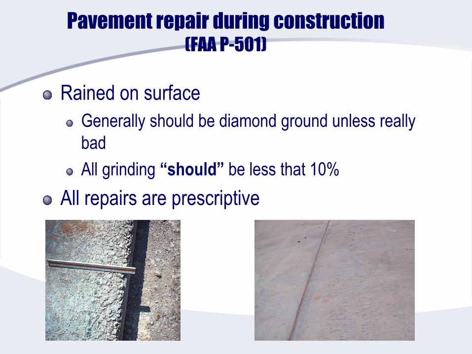
Rained on surface
Generally should be diamond ground unless really
bad
All grinding “should” be less that 10%
All repairs are prescriptive
In summary
Airfield pavement construction is difficult
Requirements are strict!
Mistakes are difficult to resolve
Many opportunities for conflicts or open interpretation
Invest time and READ the specifications
Use Pre-bid meeting to clarify and define
Understand the intent – try to avoid surprises
Communicate & Coordinate & Inform