Embed Size (px)
Citation preview
RULES FORCLASSIFICATION OF
SHIPS / HIGH SPEED, LIGHT CRAFT ANDNAVAL SURFACE CRAFT
NEWBUILDING
MATERIALS AND WELDING
PART 2 CHAPTER 3
FABRICATION AND TESTING OF SHIP STRUCTURESJULY 2010This chapter has been amended since the main revision (July 2010), most recently in January 2011. See “Changes” on page 2.
CONTENTS PAGE
Sec. 1 General Requirements.......................................................................................................... 6Sec. 2 Requirements for Builders of Ship Structures ..................................................................... 9Sec. 3 Qualification of Welders.................................................................................................... 10Sec. 4 Welding Consumables ....................................................................................................... 11Sec. 5 Welding Procedures ........................................................................................................... 15Sec. 6 Fabrication and Tolerances ................................................................................................ 38Sec. 7 Non Destructive Testing of Welds..................................................................................... 42Sec. 8 Structural and Tightness Testing ....................................................................................... 46
DET NORSKE VERITASVeritasveien 1, NO-1322 Høvik, Norway Tel.: +47 67 57 99 00 Fax: +47 67 57 99 11

CHANGES IN THE RULES
GeneralThe present edition of the rules includes amendments and additions approved by the Executive Committee as of June 2010and supersedes the January 2005 edition of the same chapter.The rule changes come into force as described below.This chapter is valid until superseded by a revised chapter.
Amendments January 2011• Sec.1 General Requirements— ISO reference in Sec.1 B has been updated.
Main Changes coming into force 1 January 2011• Sec.5 Welding Procedures— Updating on qualification of welding procedures in order to be in accordance with IACS UR W28.
• Sec.8 Structural and Tightness Testing— References to SOLAS in Table B1 are replaced with text from IACS “Draft Guidelines for Procedures of Testing
Tanks and Tight Boundaries”.
Corrections and ClarificationsIn addition to the above stated rule requirements, a number of corrections and clarifications have been made in the existingrule text.
The electronic pdf version of this document found through http://www.dnv.com is the officially binding version© Det Norske Veritas
Any comments may be sent by e-mail to [email protected] subscription orders or information about subscription terms, please use [email protected] Typesetting (Adobe Frame Maker) by Det Norske Veritas
If any person suffers loss or damage which is proved to have been caused by any negligent act or omission of Det Norske Veritas, then Det Norske Veritas shall pay compensation tosuch person for his proved direct loss or damage. However, the compensation shall not exceed an amount equal to ten times the fee charged for the service in question, provided thatthe maximum compensation shall never exceed USD 2 million.In this provision "Det Norske Veritas" shall mean the Foundation Det Norske Veritas as well as all its subsidiaries, directors, officers, employees, agents and any other acting on behalfof Det Norske Veritas.

Amended January 2011, see page 2 Rules for Ships / High Speed, Light Craft and Naval Surface Craft, July 2010 Pt.2 Ch.3 Contents – Page 3
CONTENTS
Sec. 1 General Requirements ....................................................................................................................... 6
A. General ........................................................................................................................................................................... 6A 100 Application............................................................................................................................................................ 6A 200 Basic requirements................................................................................................................................................ 6A 300 Builders and subcontractors .................................................................................................................................. 6
B. Definitions ...................................................................................................................................................................... 7B 100 Terms .................................................................................................................................................................... 7
C. Documentation Requirements ..................................................................................................................................... 8C 100 Plans and particulars ............................................................................................................................................. 8C 200 Ship construction file ............................................................................................................................................ 8
Sec. 2 Requirements for Builders of Ship Structures ................................................................................ 9
A. General ........................................................................................................................................................................... 9A 100 Application............................................................................................................................................................ 9A 200 Basic requirements................................................................................................................................................ 9
B. Survey Arrangement..................................................................................................................................................... 9B 100 Quality management system................................................................................................................................. 9
C. Workmanship and Supervision ................................................................................................................................... 9C 100 General.................................................................................................................................................................. 9
Sec. 3 Qualification of Welders .................................................................................................................. 10
A. General ......................................................................................................................................................................... 10A 100 Application.......................................................................................................................................................... 10A 200 Requirements ...................................................................................................................................................... 10
B. Qualification testing and certification....................................................................................................................... 10B 100 General................................................................................................................................................................ 10B 200 Certification ....................................................................................................................................................... 10
Sec. 4 Welding Consumables...................................................................................................................... 11
A. General ......................................................................................................................................................................... 11A 100 Application.......................................................................................................................................................... 11A 200 Basic groups and grades...................................................................................................................................... 11
Sec. 5 Welding Procedures ......................................................................................................................... 15
A. General ......................................................................................................................................................................... 15A 100 Application.......................................................................................................................................................... 15A 200 Wide gap welding ............................................................................................................................................... 15A 300 Welding processes .............................................................................................................................................. 15
B. Welding Procedure Specification .............................................................................................................................. 15B 100 General................................................................................................................................................................ 15B 200 Approved welding procedure specification ........................................................................................................ 16
C. Welding Procedure Test Assembly and sampling of Test Pieces............................................................................ 16C 100 Butt welds in plates............................................................................................................................................. 16C 200 Butt welds in pipes.............................................................................................................................................. 19C 300 Full penetration T-, Y-, and K- joints ................................................................................................................. 19C 400 Branch connection .............................................................................................................................................. 20C 500 Fillet welds.......................................................................................................................................................... 21
D. Non Destructive Testing of Test Assemblies............................................................................................................. 22D 100 Butt welds and full penetration T-joints ............................................................................................................. 22D 200 Fillet welds and partial penetration welds .......................................................................................................... 22
E. Destructive Testing ..................................................................................................................................................... 23E 100 Transverse tensile test ........................................................................................................................................ 23E 200 Bend test ............................................................................................................................................................. 23E 300 Macrosection and hardness testing ..................................................................................................................... 23E 400 Impact testing...................................................................................................................................................... 23E 500 Welds between different material grades............................................................................................................ 24E 600 Retesting ............................................................................................................................................................. 24
DET NORSKE VERITAS

Rules for Ships / High Speed, Light Craft and Naval Surface Craft, July 2010 Amended January 2011, see page 2Pt.2 Ch.3 Contents – Page 4
F. Validity of Approved Welding Procedures............................................................................................................... 25F 100 General................................................................................................................................................................ 25F 200 Range of qualification......................................................................................................................................... 25
G. Additional Requirements WPQT for Liquefied Gas Systems ............................................................................... 28G 100 Welds in plates and pipes.................................................................................................................................... 28G 200 Test requirements................................................................................................................................................ 29G 300 Weld production test requirements ..................................................................................................................... 29
H. Additional Requirements WPQT for Ferritic-Austenitic Stainless Steel (Duplex) .............................................. 29H 100 Test requirements................................................................................................................................................ 29H 200 Validity of a qualified welding procedure .......................................................................................................... 30
I. Additional Requirements WPQT for Austenitic Stainless Steel ............................................................................ 30I 100 Welds in plates and pipes.................................................................................................................................... 30I 200 Test requirements................................................................................................................................................ 30
J. Welding procedures for aluminium ......................................................................................................................... 30J 100 General................................................................................................................................................................ 30J 200 Butt welds in plates............................................................................................................................................. 31J 300 Butt welds in pipes.............................................................................................................................................. 32J 400 Branch connections............................................................................................................................................. 32J 500 Fillet welds.......................................................................................................................................................... 32J 600 Non destructive testing of test assemblies .......................................................................................................... 32J 700 Destructive testing ............................................................................................................................................. 33J 800 Range of qualification......................................................................................................................................... 33J 900 Retesting ............................................................................................................................................................. 35
K. Testing .......................................................................................................................................................................... 36K 100 General................................................................................................................................................................ 36K 200 Tensile testing at ambient temperature ............................................................................................................... 36K 300 Bend testing ........................................................................................................................................................ 36
Sec. 6 Fabrication and Tolerances............................................................................................................. 38
A. General ......................................................................................................................................................................... 38A 100 Application.......................................................................................................................................................... 38
B. Material Identification................................................................................................................................................ 38B 100 General................................................................................................................................................................ 38
C. Approval of Shop Primers.......................................................................................................................................... 38C 100 General................................................................................................................................................................ 38
D. Welding Environment................................................................................................................................................. 38D 100 General................................................................................................................................................................ 38
E. Cutting, Forming, Assembly and Welding ............................................................................................................... 38E 100 Cutting ................................................................................................................................................................ 38E 200 Forming............................................................................................................................................................... 39E 300 Assembly and Welding ...................................................................................................................................... 39
F. Repairs ......................................................................................................................................................................... 40F 100 General................................................................................................................................................................ 40F 200 Repair welding .................................................................................................................................................... 40F 300 Flame straightening ............................................................................................................................................ 40
G. Inspection and Tolerances.......................................................................................................................................... 41G 100 General................................................................................................................................................................ 41G 200 Alignment and straightness................................................................................................................................. 41G 300 Weld production test requirements ..................................................................................................................... 41
Sec. 7 Non Destructive Testing of Welds................................................................................................... 42
A. General ......................................................................................................................................................................... 42A 100 Application.......................................................................................................................................................... 42A 200 Basic requirements.............................................................................................................................................. 42
B. NDT Procedures .......................................................................................................................................................... 42B 100 General................................................................................................................................................................ 42B 200 Visual testing ...................................................................................................................................................... 43B 300 Magnetic particle testing..................................................................................................................................... 43B 400 Radiographic testing ........................................................................................................................................... 43B 500 Ultrasonic testing ................................................................................................................................................ 43B 600 Penetrant testing.................................................................................................................................................. 43
DET NORSKE VERITAS

Amended January 2011, see page 2 Rules for Ships / High Speed, Light Craft and Naval Surface Craft, July 2010 Pt.2 Ch.3 Contents – Page 5
C. Personnel Qualifications............................................................................................................................................. 43C 100 General................................................................................................................................................................ 43
D. Extent of NDT.............................................................................................................................................................. 43D 100 General................................................................................................................................................................ 43
E. Acceptance Criteria for NDT..................................................................................................................................... 44E 100 General................................................................................................................................................................ 44E 200 Non-conforming weldments .............................................................................................................................. 45
Sec. 8 Structural and Tightness Testing.................................................................................................... 46
A. General ......................................................................................................................................................................... 46A 100 Application.......................................................................................................................................................... 46
B. Testing .......................................................................................................................................................................... 46B 100 Definitions .......................................................................................................................................................... 46B 200 General requirements .......................................................................................................................................... 46B 300 Specific requirements for extent and type of testing .......................................................................................... 47
DET NORSKE VERITAS

Rules for Ships / High Speed, Light Craft and Naval Surface Craft, July 2010 Amended January 2011, see page 2Pt.2 Ch.3 Sec.1 – Page 6
SECTION 1 GENERAL REQUIREMENTS
A. GeneralA 100 Application101 This section provides general requirements for fabrication of welded structures involving parts and unitsdescribed in Pt.3. 102 Basic requirements are given in Pt.1 Ch.1 Sec.1 B300 (ship rules).103 Additional fabrication requirements for ship hull structures relating to special service and type are givenin Pt.5. 104 Fabrication and welding of piping and boilers/pressure vessels are dealt with in Pt.4 Ch.6 Sec.7 (shiprules) and Pt.4 Ch.7 Sec.8, respectively. Welding procedure qualification requirements for copper alloycastings are given in Pt.2 Ch.2 Sec.10 C900.
A 200 Basic requirements201 Welding of important structures like:
— hull, superstructure taking part in the overall strength— hull equipment, stern frames, rudders, rudder stocks and rudder horn.
shall be carried out by certified welders, with approved welding procedures and welding consumables, and atbuilders and subcontractors complying with A300202 Welders and welding procedures approved for the type of connection and parent material in question asgiven in Sec.3 and Sec.5, respectively, shall be used. 203 Welding consumables shall be type approved. Sec.4 specifies basic groups and grades, application of thevarious grades and grouping of shielding gases.
A 300 Builders and subcontractors301 Builders and subcontractors will have to prove and document their abilities for the welding operations inquestion.302 It is assumed that the builders and subcontractors make use of the necessary equipment for carrying outinspection of the welding operations in a satisfactory manner.303 Important welding operations shall be carried out under daily supervision of an inspector, who has theexperience and qualifications which enable him to judge this type of work. The work of each welder shall beregularly examined.304 Builders and subcontractors shall keep a card index or register of all certified welders. The register shallgive information on training of the welders and date and results of qualification tests. Information about thebase metal, type of welding consumable, joint design and welding positions shall be stated in the event of re-qualification tests. The surveyor shall be allowed to examine the register at any time.
DET NORSKE VERITAS

Amended January 2011, see page 2 Rules for Ships / High Speed, Light Craft and Naval Surface Craft, July 2010 Pt.2 Ch.3 Sec.1 – Page 7
B. DefinitionsB 100 Terms101 The following terms are used in connection with fabrication of ship structures:
Builder Yard involved in fabrication planning, building, assembly and testing of ship structures for purpose of classification.
Subcontractor Independent unit performing work under supervision by the builder. The subcontractor may be required to be approved by the Society.
Quality Management System
Quality Management System worked out in accordance with a reputable quality standard, such as ISO 9001 or equivalent. The Quality Management System may be required to be certified by an accredited certification body, see Pt.1 Ch.1 Sec.4 B500 (ship rules).
New Building Survey Arrangement (NSA)
Agreement between the builder and the Society defining responsibility and authority of personnel and items to be controlled with acceptance criteria, quality control functions. The activities through this agreement are complementary to the Society’s own inspection scheme.
Welding procedure specification (WPS)
See Pt.0 Ch.3 Documentation type M060.
Preliminary welding procedure specification (pWPS):
A tentative issue of Documentation type M060, which is assumed adequate by the builder as basis for approval by the Society.
Welding procedure qualification record (WPQR)
See Pt.0 Ch.3 Documentation type M061.
WPQT Welding procedure qualification test: A test carried out in order to demonstrate that the weld carried out according to the pWPS meets the specified requirements.
WPT Weld production test: A test carried out to demonstrate that actual production welding meets the specified requirements.
NDT Non-destructive testing: Visual inspection, radiographic testing, ultrasonic testing, magnetic particle testing, penetrant testing and other non-destructive methods for revealing defects and irregularities.
Manual welding Welding where the electrode holder, welding hand gun, torch or blowpipe are manipulated by hand.
Partly mechanised welding
Manual welding where the wire feed is mechanized.
Fully mechanised welding Welding where all main operations (excluding the handling of the work piece) are mechanized.
Fully automatic processes Welding where all operations are mechanized.
DET NORSKE VERITAS

Rules for Ships / High Speed, Light Craft and Naval Surface Craft, July 2010 Amended January 2011, see page 2Pt.2 Ch.3 Sec.1 – Page 8
C. Documentation RequirementsC 100 Plans and particulars101 Documentation shall be submitted as required by Table C1.
C 200 Ship construction file201 For vessels, except for those defined in SOLAS I/3, the following documentation shall be prepared bybuilder and available on board prior to delivery:
— Z041 - Ship construction file.
Detailed description is given in Pt.0 Ch.3.
Table C1 Documentation requirementsObject Documentation type Additional description For approval (AP) or
For information (FI)Ship hull H130 – Fabrication specification For builders unknown to
the Society, on request. FI
H131 – Non-destructive testing (NDT) plan APH132 – Tank testing plan FIH133 – Erection and inspection plan FIM060 – Welding procedures APM061 – Welding procedure qualification record AP
DET NORSKE VERITAS

Amended January 2011, see page 2 Rules for Ships / High Speed, Light Craft and Naval Surface Craft, July 2010 Pt.2 Ch.3 Sec.2 – Page 9
SECTION 2 REQUIREMENTS FOR BUILDERS OF SHIP STRUCTURES
A. GeneralA 100 Application101 This section specifies general requirements to builders of ship structures, hereafter called “builders”,involved in building activities of structures intended for classification by the Society.
A 200 Basic requirements201 Prior to commencement, builders unknown to the Society shall demonstrate their capability to carry outfabrication in line with the overall requirements of this section. All builders shall comply with the criteria givenin IACS UR Z23 “Hull survey for New Construction” and provide the documentation there stated.
B. Survey ArrangementB 100 Quality management system101 Builders of hull structures shall possess a documented and implemented quality management system orif otherwise, the Society will consider extended survey scheme. The extent of the quality management systemshall be dependent on the size and type of the organisation, complexity and interaction of the processes andcompetence of personnel. 102 This section shall also apply to subcontractors of builders, when performing fabrication work definedunder the Society’s classification scope for the project. Subcontractors shall also comply with the IACS URZ23.
C. Workmanship and SupervisionC 100 General101 Builders shall ensure that works are skilfully and competently executed in accordance with fabricationprocedures and work instructions, inspection and test plans. All builders shall comply with relevant criteriagiven in IACS UR Z23.102 Builders shall ensure that all works are effectively and systematically controlled at all stages.
Guidance note:Quality requirements for welding may be based on ISO 3834-series.
---e-n-d---of---G-u-i-d-a-n-c-e---n-o-t-e---
103 Builders shall be in control of work performed at the location of subcontractors and/or of subcontractorsperforming work at the builder.
DET NORSKE VERITAS

Rules for Ships / High Speed, Light Craft and Naval Surface Craft, July 2010 Amended January 2011, see page 2Pt.2 Ch.3 Sec.3 – Page 10
SECTION 3 QUALIFICATION OF WELDERS
A. GeneralA 100 Application101 These requirements shall apply to the Society’s acceptance of welders for fusion welding of steel andnon-ferrous metals.
A 200 Requirements201 Welding operators using fully mechanized or fully automatic processes shall be required to have recordsof proficiency, which provide evidence that the operators are receiving adequate regularly training in setting,programming and operating the equipment.
B. Qualification testing and certificationB 100 General101 Welders shall be qualified to a standard recognised by the Society, e.g. EN 287, ISO 9606, ASMESection IX, ANSI/AWS D1.1.102 Recognition of other standards is subject to acceptance by the Society.
B 200 Certification 201 Welding and testing of weld assemblies shall be performed in the presence of the Society’srepresentative. Upon successful completion, and on client’s request, the Society will certify that the welder haspassed the approval testing.202 Where certification is performed by an other recognized classification society or independentorganisations e.g. accredited or nationally approved certification bodies, recognition of such certification willbe evaluated on a case by case basis. The Society reserves the right, however, to require verification of welders’qualifications when deemed necessary. Such verification may include testing prior to production, extra NDTand/or welding production tests.
DET NORSKE VERITAS

Amended January 2011, see page 2 Rules for Ships / High Speed, Light Craft and Naval Surface Craft, July 2010 Pt.2 Ch.3 Sec.4 – Page 11
SECTION 4 WELDING CONSUMABLES
A. GeneralA 100 Application101 This section specifies basic groups and grades for type approved welding consumables, application ofthe various grades and grouping of the shielding gases.
A 200 Basic groups and grades201 Welding consumables are divided into groups, depending on the strength of the filler metal and furtherdivided into grades depending on the impact test temperature and the chemical composition of the filler metal.The grades of welding consumables are specified in Table A1.
202 Welding consumables which have satisfied the requirements for a higher toughness grade, are alsoconsidered as complying with the requirements for a lower toughness grade of the same group.203 The following tables (Table A2 - Table A7) show which welding consumables that can be applied forvarious steel grades.When two different steel grades shall be joined, the welding consumable shall have a yield strength not belowthat of the lower strength steel. When welding high strength steels of grade E, it is recommended that the applied welding consumable havebeen tested at -40°C (grade 4 or IV).204 Where applicable, the composition of the shielding gas shall be reported. The approval of a wire /gascombination with any particular gas can be applied to or transferred to any combination of the same wire andany gas in the same numbered group as defined in Table A8.
Table A1 Correlation of welding consumables to hull structural steels (see notes)Normal strength steels High strength steels Extra high strength
steelsAustenitic stainless
steels
Grade of welding consumables
1235
IIIIIIV
2 Y3 Y4 Y5 Y
2/3/4/5 Y40
I YII YIII YIV YV Y
II/III/IV/V Y40
3/4/5 Y42III/IV/V Y42
3/4/5 Y46III/IV/V Y46
3/4/5 Y50III/IV/V Y50
3/4/5 Y55III/IV/V Y55
3/4/5 Y62III/IV/V Y62
3/4/5 Y69III/IV/V/ Y69
308 /308Mo/ 308L309 /309L/ 309Nb/309 Mo/309Mo L
310/310 Nb/310Mo312
316/ 316 L317/317 L
318330347349
Notes:
— Grades 1,2, 3, 4 and 5 mean covered electrodes; grades I, II, III, IV and V mean other consumables.— Increasing number means increasing impact toughness test requirements (test temperature grade 1/I:20ºC, grade V:-
60ºC.— Y means high strength steels.— Y followed by a number means extra high strength steels of corresponding strength (×10).
DET NORSKE VERITAS

Rules for Ships / High Speed, Light Craft and Naval Surface Craft, July 2010 Amended January 2011, see page 2Pt.2 Ch.3 Sec.4 – Page 12
Table A2 Correlation of welding consumables to hull structural steelsHull
structural steel grade
Grade of welding consumables1 (DP) 2 2 Y 1) 2 Y40 1) 3 3 Y 1) 3 Y40 1) 4 Y 1) 4 Y40 1) 5 Y 1)
NV ANV BNV DNV E
X XXX
XXX
XXXX
XXXX
XXXX
XXXX
NV A27SNV D27SNV E27S
XX
XX
XXX
XXX
XXX
XXX
XXX
NV A32/36NV D32/36NV E32/36NV F32/36
XX
XX
XXX
XXX
XXXX
XXXX
XXXX
NV A40NV D40NV E40NV F40
XX
XXX
XXXX
1) To have Hydrogen mark H15, H10 or H5.
Table A3 Correlation of welding consumables to hull structural steelsHull
structural steel grade
Grade of welding consumables1 I Y II II Y II Y40 III III Y III Y40 IV Y IV Y40 V Y
NV ANV BNV DNV E
X X XXX
XXX
XXXX
XXXX
XXXX
XXXX
NV A27SNV D27SNV E27S
X XX
XX
XXX
XXX
XXX
XXX
XXX
NV A32/36NV D32/36NV E32/36NV F32/36
X XX
XX
XXX
XXX
XXXX
XXXX
XXXX
NV A40NV D40NV E40NV F40
XX
XXX
XXXX
Table A4 Correlation of welding consumables to boilers and pressure vessel steels and steels for low temp. service
For welding of steel grade
Grade of welding consumables1(DP) 2 2Y 1) 2Y 40
1)3 3Y 1) 3Y40 1) 4Y 1) 4Y40 1) 5 5Y 1)
NV 360-ONNV 360-1FNNV 360-2FNNV 410-ONNV 410-1FNNV 460-ONNV 460-1FN
X XX
XX
XXXX
XXXX
XXX
XXXXXXX
XXX
XXXXXXX
XXX
XXX
XXXXXX
NV 490-ONNV 490-1FNNV 510-1FN
XX
XXX
XX
XXX
XX
XXX
XXX
NV 2-2NV 2-3NV 2-4 (L)NV 4-2NV 4-3NV 4-4 (L)
X X
X
X
X
XX
XX
XX
XX
XXX
XXX XXX
1) To have Hydrogen mark H15, H10 or H5.
DET NORSKE VERITAS

Amended January 2011, see page 2 Rules for Ships / High Speed, Light Craft and Naval Surface Craft, July 2010 Pt.2 Ch.3 Sec.4 – Page 13
Table A5 Correlation of welding consumables to boilers and pressure vessel steels and steels for low temp. serviceFor welding of steel grade
Grade of welding consumables1 I Y II II Y II Y40 III III Y III Y40 IV Y IV Y40 V Y
NV 360.ONNV 360-1FNNV 360-2FNNV 410-ONNV 410-1FNNV 460-ONNV 460-1FN
X X
X
X
XX
XX
XXXX
XXXX
XXX
XXXXXXX
XXX
XXXXXXX
XXX
XXXXXX
NV 490-ONNV 490-1FNNV 510-1FN
X XX
XXX
XX
XXX
XX
XXX
XXX
NV 2-2NV 2-3NV 2-4 (L)NV 4-2NV 4-3NV 4-4 (L)
X X
X
X
X
XX
XX
XX
XX
XXX XXX
DET NORSKE VERITAS

Rules for Ships / High Speed, Light Craft and Naval Surface Craft, July 2010 Amended January 2011, see page 2Pt.2 Ch.3 Sec.4 – Page 14
Table A6 Correlation of welding consumables to hull structural steelsFor welding of
steel gradeGrade of welding consumable
Y42H10 1) Y46H10 1) Y50H10 1) Y55H5 Y62H5 Y69H5NV D420NV E420NV F420
3/III, 4/IV, 5/V4/IV, 5/V
5/V
3/III, 4/IV, 5/V4/IV, 5/V
5/V
3/III, 4/IV, 5/V4/IV, 5/V
5/VNV D460NV E460NV F460
3/III, 4/IV, 5/V4/IV, 5/V
5/V
3/III, 4/IV, 5/V4/IV, 5/V
5/VNV D500NV E500NV F500
3/III, 4/IV, 5/V4/IV, 5/V
5/V
3/III, 4/IV, 5/V4/IV, 5/V
5/VNV D550NV E550NV F550
3/III, 4/IV, 5/V4/IV, 5/V
5/V
3/III, 4/IV, 5/V4/IV, 5/V
5/VNV D620NV E620NV F620
3/III, 4/IV, 5/V4/IV, 5/V
5/V
3/III, 4/IV, 5/V4/IV, 5/V
5/VNV D690NV E690NV F690
3/III, 4/IV, 5/V4/IV, 5/V
5/V1) May have hydrogen mark H5
Table A7 Selection of suitable consumables for combinations of aluminium alloys
Base metal alloyNV-5052, NV-5754NV-5154, NV-5454
NV-5086
NV-5083NV-5383NV-5059
NV-6060, NV-6061NV-6063, NV-6005A
NV-6082NV-5052, NV-5754NV-5154, NV-5454
NV-50865356, 5556, 5183 5356, 5556, 5183 5356, 5556, 5183
NV-5083, NV-5383NV-5059 5356, 5556, 5183 5183 1) 5356, 5556, 5183
NV-6060, NV6061NV-6063, NV-6005A
NV-60825356, 5556, 5183 5356, 5556, 5183 5356, 5556, 5183
Note: All consumables are covered by the AWS specification. The prefix “ER” is committed.
1) Other consumables may be use if allowable stresses are reduced.
Table A8 Grouping of shielding gases, 1)
Group Gas composition (Vol.%)CO2 O2 H2 He Ar
I 1I 2I 3
100> 0-95
100
RestM 11M 12M 13M 14
> 0 - 5> 0 - 5
> 0 - 5> 0 - 3> 0 - 3
> 0 - 5 Rest 2)Rest 2)Rest 2)Rest 2)
M 21M 22M 23
> 5 - 25
> 5 - 25> 3 - 10> 0 - 8
Rest 2)Rest 2)Rest 2)
M 31M 32M 33
> 25 - 50
> 5 - 50> 10 - 15> 8 - 15
Rest 2)Rest 2)Rest 2)
C 1C 2
100Rest > 0 - 30
1) The compositions of shielding gasses in group I are in accordance with EN 439, while group M and C gasses are in accordance with IACS W17:1993.
2) Argon may be partly substituted by Helium up to 95% of the Argon content.
DET NORSKE VERITAS

Amended January 2011, see page 2 Rules for Ships / High Speed, Light Craft and Naval Surface Craft, July 2010 Pt.2 Ch.3 Sec.5 – Page 15
SECTION 5 WELDING PROCEDURES
A. GeneralA 100 Application101 This section specifies requirements for welding procedure specifications and welding procedurequalification tests for C-Mn and low alloy steels, aluminium, austenitic stainless steel and feritic-austenic(duplex) stainless steels. C-Mn and low alloy steels are in this context referred to as “steels”.
A 200 Wide gap welding201 Wide gap welding / buttering of the weld groove should when the gap is above 10 mm, be qualified, bya separate WPQT. In the WPQT the largest gap in production shall be used. This applies when the essentialvariables for the buttering process are different than the essential variables for the process used for subsequentcompletion of the joint and/or the thickness of the buttering exceed 8 mm each side of the bevel.The buttered area shall be 100% tested with MT (ferromagnetic materials) or PT (non-magnetic materials)before the filling of the groove starts. No surface linear indications are accepted. For typical butt- and fillet weldplate edge preparation repairs, guidance is given to IACS REC. No.47 Shipbuilding and Repair QualityStandard, Part A.
A 300 Welding processes301 Welding may be performed with the following processes unless otherwise specified:
— manual metal arc welding (metal arc welding with covered electrode)— self-shielded tubular-cored arc welding— submerged arc welding (SAW) — submerged arc welding with strip electrode— metal inert gas welding, (MIG) welding— metal active gas welding, (MAG) welding— tubular-cored metal arc welding with active gas shield— tubular-cored metal arc welding with inert gas shield— gas tungsten arc welding (GTAW)— plasma arc welding.
302 Other processes shall be specially approved.
B. Welding Procedure SpecificationB 100 General101 A welding procedure specification shall as a minimum contain the following information as relevant forthe welding operation:
— material: standard, grade and modification— nominal thickness or diameter range (dimensions) — welding process— joint or groove design with tolerances— welding position(s) and direction of progression— welding consumables: trade name, electrode or wire diameter, shielding gas, flux and recognised
classification— welding sequence: number and order of passes or layers— electrical parameters: voltage range, current range, polarity— travel speed- and heat input ranges— preheat and interpass temperatures— post weld heat treatment parameters— details on cleaning processes employed and restrictions if any.
102 A welding procedure specification (WPS) shall be prepared by the builder or subcontractor whichintends to perform the welding procedure qualification test (WPQT). This document is also referred to as apreliminary welding procedure specification (pWPS). The pWPS can be modified and amended duringprocedure tests as deemed necessary, however, it is to define all relevant variables as mentioned in the WPS.103 The builder or subcontractor shall submit to the Society a pWPS for review prior to the tests. In case that
DET NORSKE VERITAS

Rules for Ships / High Speed, Light Craft and Naval Surface Craft, July 2010 Amended January 2011, see page 2Pt.2 Ch.3 Sec.5 – Page 16
the test pieces welded according to the pWPS show unacceptable results, the pWPS shall be adjusted by thebuilder or subcontractor. The new pWPS shall be prepared and the test pieces welded in accordance with thenew pWPS.
104 The WPS shall be used as a basis for the production welds, and upon satisfactory completion of the testsbased upon the pWPS, the Society may approve it as a WPS. In case that a WPS is approved by the Society theapproval range shall be in compliance with F.
B 200 Approved welding procedure specification
201 Welding procedure specifications shall be approved by the Society prior to welding.
202 A welding procedure specification may be approved based on one of the following alternatives:
a) Review of a welding procedure qualification test record (WPQR) corresponding to the welding procedurespecification in question. The welding procedure test on which the WPQR is based shall be witnessed bythe Society or by a party recognised by the Society.
b) Review and verification of documentation showing successful application of the welding procedurespecification over a prolonged period of time.
c) The welding procedure specification is compiled on basis of other approved welding procedures.
203 For the following type of services the approval of welding procedure specifications shall be based onalternative 202 a):
— butt welds used in cargo tanks, process pressure vessels and/or piping systems for liquefied gases— all welds in aluminium — butt welds and essential fillet welds used in cargo tanks, hull structure and process pressure vessels.— piping systems in ferritic-austenitic stainless steels— butt welds in plate thickness above 50 mm— butt welds of material grade E and F single-side buttwelds with and without backing in the vertical down
positions, welded connections between castings/forgings and rolled material, such as e.g. stern frames,rudder, rudder horns and struts. welding of highly stressed butt welds and cruciform joints located at largehatch openings
— when welding consumables are not type approved.
204 When a welding procedure qualification test (WPQT) is required, the tests must be performed in theenvironment applicable to the actual production and meet the specified minimum requirements.
205 Preparation and welding of test pieces shall be carried out in accordance with the pWPS and under thegeneral condition of production welding which it represents.
C. Welding Procedure Test Assembly and sampling of Test Pieces
C 100 Butt welds in plates
101 The test assembly consists of two plates welded together. For normal and high strength steel grades (refPt.2Ch.2Sec.1A200) impact tested in the longitudinal direction, the butt weld of the test assembly isperpendicular to the rolling direction of the two plates. For extra high strength steel grades impact tested in thetransverse direction, the butt weld of the assembly is parallel to the rolling direction of the two plates. As faras possible the plates shall have a size which can simulate the heat transfer during the production welding. Formanual or semiautomatic welding, a test assembly according to Fig.1 shall be carried out with:
lmin = 300 mmLmin= 350 mm
For automatic welding, the dimensions shall be:
lmin = 400 mmLmin= 1 000 mm
Edge preparation and fit-up shall be as detailed in the pWPS. The plates shall be joined and held by tack weldsto provide the correct gap for the edge preparation used. 50 mm of each end of the test piece shall be discarded.
DET NORSKE VERITAS

Amended January 2011, see page 2 Rules for Ships / High Speed, Light Craft and Naval Surface Craft, July 2010 Pt.2 Ch.3 Sec.5 – Page 17
Fig. 1Test assembly for butt welds in plates
102 The following mechanical tests are required from each assembly (see Fig.2):
— 2 tensile test (flat specimen transverse to the weld)— two root and two face bend specimens shall be tested. For thickness 12 mm and over, four side bend
specimens may alternatively be tested — when the welding consumable is not approved, 1 extra tensile test (round specimen from the weld metal)
(project specific requirement)— 12 Charpy V-notch tests with the notch location as given in 107— 1 macrosection test (metallographic examination + hardness measurements).
103 Specimens for transverse tensile testing shall be in accordance with K200, type B.
Plate rolling direction
(Steel platesKVL-tested)
DET NORSKE VERITAS

Rules for Ships / High Speed, Light Craft and Naval Surface Craft, July 2010 Amended January 2011, see page 2Pt.2 Ch.3 Sec.5 – Page 18
Fig. 2Sampling of test specimens in plates
104 When required the round tensile specimen shall be machined to the dimensions shown in K200, type A,care being taken that the longitudinal axis coincides with the intersection between the midplane of the weld,and the midplane of the plates. If the section area of the weld metal is too small to allow sampling of the roundspecimen, an all-weld-metal tensile test shall be carried out.
105 Transverse side bend, root bend and face bend specimens shall be machined to the dimensions shown inK300. For a mixed or heterogeneous butt joint, longitudinal bend test specimens may replace transverse bendtest specimens.
106 The macrosection shall include about 10 mm of unaffected base material and shall be prepared andetched on one side to clearly reveal the fusion line and the HAZ
107 The Charpy V-notch specimens shall be machined in accordance with the requirements given in Ch.1Sec.2 (ISO148). The specimens shall be sampled 2 mm below the surface of the parent material and transverseto the weld.12 Charpy V-notch specimens shall be localized in the welded joint as follows:
— 3 specimens with the notch along the weld metal centreline(WM)— 3 specimens with the notch in the fusion line (FL)— 3 specimens with the notch in the HAZ, 2 mm from the fusion line (FL+2)— 3 specimens with the notch in the HAZ, 5 mm from the fusion line (FL+5).
108 HAZ impact test specimens are normally not required for grade NVA steels, aluminium and austeniticstainless steels with service temperature above -105 degrees Celsius. For material thicknesses below 6 mmimpact testing is not required unless specifically required by the Society. The V-notch shall be perpendicularto the plate surface. For plate thicknesses >50 mm, two additional sets of specimens shall be taken from theroot area: one with the notch in the centre of the weld and one with the notch in the fusion line. Where multiple welding processes are qualified in a single test piece, impact test specimens shall be taken fromthe weld metal and HAZ that include each process. This does not apply to the process and consumables usedto make the first weld run or root deposit.For dissimilar metal joints and/or joints between cast or forged and rolled materials, impact tests shall becarried out on test specimens with notch in fusion line, 2 mm from fusion line and 5 mm from fusion line ineach parent material.
50 mm
Macro / hardness testFlat tensile test
Face bend test
Root bend test
Round tensile test
}or 2side bendtests
CharpyV - notchtests
Weld metal
Fusion line
HAZ + 2 mm
HAZ + 5 mm
50 mm
t
Discard
Discard
Flat tensile test
Face bend test
Root bend testside bendtests
or 2}
DET NORSKE VERITAS

Amended January 2011, see page 2 Rules for Ships / High Speed, Light Craft and Naval Surface Craft, July 2010 Pt.2 Ch.3 Sec.5 – Page 19
C 200 Butt welds in pipes201 The test assembly shall be in accordance with Fig.3.
a = minimum value 150 mmD = outside diameter.Fig. 3Test assembly for butt welds in pipes
202 The following mechanical tests are required from each assembly (see Fig.4):
— 2 tensile test (flat specimen transverse to the weld)— 1 root and 1 face bend tests when t ≤ 20 mm and 2 side bend tests when t > 20 mm— 12 Charpy V-notch tests with the notch location as given in 107— 1 macrosection test (metallographic examination + hardness measurements).
Fig. 4Sampling of test specimens in pipes
C 300 Full penetration T-, Y-, and K- joints301 WPQT's for full penetration groove welds between plates at right angles or inclined, i.e. T- or Y- and K-configurations, shall cover a weld length of minimum 350 mm (see Fig.5).
Edge preparation and fit-up as detailed in the pWPS
D
aa
WELD METAL
FUSION LINEHAZ + 2 mm
HAZ + 5 mm
BEND TESTSTENSILE TEST
HARDNESS/MACRO TEST
CHARPYV-NOTCH
TESTS
TENSILE TEST
DET NORSKE VERITAS

Rules for Ships / High Speed, Light Craft and Naval Surface Craft, July 2010 Amended January 2011, see page 2Pt.2 Ch.3 Sec.5 – Page 20
a = 3 t; minimum value 150 mmb = 6 t; minimum value 350 mm
Fig. 5Test assembly for full penetration T-joints
302 The following mechanical tests are required from each assembly (see Fig.6):
— 12 Charpy V-notch tests with the notch location as given in 107— 1 macrosection test (metallographic examination + hardness measurements).
Fig. 6Sampling of test specimens in full penetration T-joints
C 400 Branch connection401 The following mechanical tests are required from each assembly (see Fig.7):
— 12 Charpy V-notch tests sampled at 9 o'clock in the branch pipe and with the notch location as given in 107— two macrosection tests (metallographic examination + hardness measurements) at 12 and 6 o'clock.
Edge preparation and fit-up as detailed in the pWPS
bba
WELD METAL
FUSION LINE
HAZ + 2 mm
HAZ + 5 mmHARDNESS MACRO TEST
CHARPYV-NOTCHTESTS
DET NORSKE VERITAS

Amended January 2011, see page 2 Rules for Ships / High Speed, Light Craft and Naval Surface Craft, July 2010 Pt.2 Ch.3 Sec.5 – Page 21
a = minimum value 150 mm D1= outside diameter of the main pipe t1 = wall thickness of the main pipe D2= outside diameter of the branch pipe t2 = wall thickness of the branch pipe.Fig. 7Test assembly for branch connections
C 500 Fillet welds501 For plate fillet welds, the two plates are assembled and positioned edgewise so as to constitute a tee-assembly with no clearance. As far as possible the plates shall be of a sufficient size to ensure a reasonable heatdistribution. For plate fillet welds the test assembly shall be as defined in Fig.8.
Fig. 8Test assembly for plate fillet welds
D2
D1
Edge preparation and fit-up as detailed in the pWPS t2
a
a
a
α
12
96
t1
150
a
L
150
DET NORSKE VERITAS

Rules for Ships / High Speed, Light Craft and Naval Surface Craft, July 2010 Amended January 2011, see page 2Pt.2 Ch.3 Sec.5 – Page 22
Fig. 9Test assembly for pipe fillet welds
For manual and semi-automatic welding the length of the test piece shall be:
Lmin= 350 mm.
For automatic welding the length shall be:
Lmin= 1 000 mm.
Weld and fit-up shall be as detailed in the pWPS. The test assembly shall be welded on one side only. However,for automatic two side fillet welding (tandem technique), welding from two sides is acceptable. For manual andsemi-automatic welding, the stop/restart position is normally to be included in the test length and shall beclearly marked for subsequent examination. The ends of the specimen are exempted from examination over alength of 50 mm.502 The following tests shall be performed:
— two macrosection tests (metallographic examination, hardness measurements). One of the macrosectionsshall be taken at the marked position of the stop/restart (for more details see 106). For hardness testing, seeE302.
— one fracture test. Shall be performed by folding the upright plate onto the through plate. Evaluation is toconcentrate on cracks, porosity and pores, inclusions, lack of fusion and incomplete penetration.Imperfections that are detected shall be assessed in accordance with ISO 5817 level B.
When the shop primer is not approved refer to Section 6C, extra testing according to Type ApprovalProgramme 1-602.2 is required. 503 The tests to be performed on pipe fillet welds shall be in accordance with an international recognisedstandard. Test assembly is shown in Fig. 9.
D. Non Destructive Testing of Test Assemblies
D 100 Butt welds and full penetration T-joints101 The extent of the testing shall be as follows:
— 100% visual inspection— 100% radiographic or ultrasonic testing— 100% surface crack detection (MT for ferromagnetic materials or PT for non-ferromagnetic materials).
The soundness of the weld shall comply, unless otherwise specified, with ISO 5817 level B for ferrousmaterials or ISO 10042 level B for aluminium.
D 200 Fillet welds and partial penetration welds201 The extent of the testing shall be as follows:
DET NORSKE VERITAS

Amended January 2011, see page 2 Rules for Ships / High Speed, Light Craft and Naval Surface Craft, July 2010 Pt.2 Ch.3 Sec.5 – Page 23
— 100% visual inspection— 100% surface crack detection (MT for ferromagnetic materials or PT for non-ferromagnetic materials).
The soundness of the weld shall comply, unless otherwise specified, with ISO 5817 level B for ferrousmaterials or ISO 10042 level B for aluminium. If the stop/restart spot is included in the test length, specialattention shall be paid to this position with respect to profile, proper fusion and absence of crater defects.
E. Destructive TestingE 100 Transverse tensile test 101 The tensile strength shall not be below the specified minimum tensile strength for the steel grade inquestion.
E 200 Bend test201 The test specimens shall be bent on a mandrel with diameter 4xt, where t is the thickness of the specimen,except for extra high strength steels grades 550, 620, and 690 where the diameter shall be 5xt. The bendingangle shall be at least 180°. After bending, the test specimens shall not reveal any open defects in any directiongreater than 3 mm. Defects appearing at the corners of a test specimen during testing shall be investigated caseby case.
E 300 Macrosection and hardness testing301 Cracks and lack of fusion are not accepted. The welded joints shall have a regular profile with smoothtransitions to the base materials and without significant or excessive reinforcement. 302 The hardness testing shall be in accordance with ISO 6507/1 or equivalent, and is only required forgrades NV27S and higher. Normally, the Vickers method (HV10) is used. Indentations shall be made alongtraverses in the weld, HAZ and the parent metal approximately 1 mm below the surface. For each traverse aminimum of 3 indentations shall be made in the weld, HAZ (both sides) and parent metal (both sides). For HAZthe first indentation shall be placed as close to the fusion line as possible. For double sided welds, for fillet andT-butt welds, one additional row of indentations shall be made through the root area.303 For material grades up to and including NV 420 a maximum hardness limit of 350 HV10 shall be met.For NV 460, NV 500, NV 550, NV 620 and NV 690 grades the maximum hardness limit shall be 420 HV10.For single run fillet welds a maximum hardness limit of 380 HV10 shall be met.
E 400 Impact testing401 Hull constructionThe test temperature and absorbed energy shall be in accordance with the following requirements:
Guidance note:The average value for absorbed energy in (WM), (FL) and HAZ shall not be less than 27 J at 20°C for NVA and NVB.
---e-n-d---of---G-u-i-d-a-n-c-e---n-o-t-e---
The average value for absorbed energy in (WM), (FL) and HAZ shall not be less than:
— for manual and semi-automatic welding in all welding positions except vertical: 47 J— for automatic welding and fully mechanised welding: 34 J (NV 40 grades 39 J)— for manual and semi-automatic welding in vertical position: 34 J (NV 40 grades 39 J).
For extra high strength structural steels and weldable C- and C-Mn hull steel castings and forgings, the CharpyV-notch test temperature and the average value for absorbed energy in weld metal, fusion line and HAZ shallbe the same as required for the base material.402 For pressure vessels and production/drilling plants related equipment, structures and systems the CharpyV-notch test temperature and the average value for absorbed energy in weld metal, fusion line and HAZ shallbe the same as required for the base material.403 The average impact requirements shall be satisfied for each notch location, but one single value of threevalues from specimens from the same notch location may be below the average requirements, but not below
Impact test temperatures: For grades:+20°C A, A27S, A32, A36 and A40
0°C B, D, D27S, D32, D36 and D40-20°C E, E27S, E32, E36 and E40-40°C F32, F36 and F40
DET NORSKE VERITAS

Rules for Ships / High Speed, Light Craft and Naval Surface Craft, July 2010 Amended January 2011, see page 2Pt.2 Ch.3 Sec.5 – Page 24
70% of minimum average. 404 In the case of reduced Charpy V-notch test specimens (10 × 7.5 mm and 10 × 5 mm), the impact energyvalues to be obtained shall satisfy Table E1:
405 Where the results from a set of three impact test specimens do not comply with the requirements, anadditional set of three impact test specimens may be taken. The results obtained shall be combined with theoriginal results to form a new average which, for acceptance, shall be not less than the required value.Additionally, for these combined results not more than two individual values shall be less than the requiredaverage value, and of these, not more than one shall be less than 70% of the average value.
E 500 Welds between different material grades501 When a butt weld is made between two plates of different grades, the test temperature and achievedimpact energy shall comply with the minimum specified requirements for the lower steel grade (see E401 andE402). In the same way, the tensile strength to be obtained on the welded assembly shall be in agreement withthe requirements relating to the plate steel having the lower strength. As an example the test temperature,impact energy and tensile strength for the butt welded joints given in Fig.10 are those required for the plate ofgrade D in the left assembly and for the plate of grade E in the right assembly.
Fig. 10Butt welded plate joints of different grades
E 600 Retesting601 If the WPQT fails to comply with any of the requirements for NDT one extra WPQT shall be welded andsubjected to the same testing. If this additional test does not meet the relevant requirements, the actual pWPSshall be considered as not qualified and a re-specification of the pWPS shall be made prior to a newqualification test.If the result of any destructive test fails to meet the requirements, two further tests may be made from the samewelded joint if there is sufficient material available. If not, a new assembly shall be welded using the sameWPS. If either of these additional test specimens does not comply with the relevant requirements, the WPS shallbe regarded as not capable of complying with the requirements without modification.
Table E1 Impact energy requirement for subsize specimens Dimensions of Charpy V-notch test specimen Impact
energy 10 × 10 mm KV10 × 7.5 mm 5/6 KV10 × 5 mm 2/3 KV
grade Egrade D
grade E grade EH
DET NORSKE VERITAS

Amended January 2011, see page 2 Rules for Ships / High Speed, Light Craft and Naval Surface Craft, July 2010 Pt.2 Ch.3 Sec.5 – Page 25
F. Validity of Approved Welding Procedures
F 100 General
101 The validity of an approved WPS shall be restricted to the builder or subcontractor performing thequalification or receiving the approval. It is a prerequisite that the workshops/yards belonging to the builderand/or subcontractor are under the same technical management and working in accordance with the same QA– program and – procedures.
102 Qualification of a welding procedure remains valid provided the parameters are kept within the qualifiedranges during production welding. The qualified ranges are given in F 200. When one or more variationsoutside the qualification ranges occur, the welding procedure qualification shall be considered invalid, and thewelding procedure is therefore to be re-specified and re-qualified.
Guidance note:Note that a qualified procedure is always based on a welding procedure test (WPQT) and that approval of a WPS based ona welding procedure test is only required for the type of services listed in B203.
---e-n-d---of---G-u-i-d-a-n-c-e---n-o-t-e---
F 200 Range of qualification
201 A qualified welding procedure shall be used within the ranges of the parameters below.Base materialThe following changes shall lead to a new qualification:
a) In general, significant change of material properties which will obviously affect the weldability andmechanical properties.- A change from wrought (rolled, forged) steel to cast steel or vice versa will require a new welding
procedure qualification. - Approval of quenched and tempered steels does not qualify thermo-mechanically rolled steels (TM
steels) and vice versa.- Approval of quenched and tempered hull steel forgings does not qualify other delivery conditions and
vice versa.- Approval of quenched and tempered hull steel castings does not qualify other delivery conditions and
vice versa.b) More specifically, structural steels are grouped in three categories:
i) Normal strength steel, grades A, B, D and E or equivalent structural steels with tensile strength 400–520 N/mm2.
ii) High strength steel, grades A27S, D27S, E27S, A32, D32, E32, F32, A36, D36, E36, F36, A40, D40,E40, F40 or equivalent structural steels with minimum specified yield strength 265–390 N/mm2.
iii) Extra high strength steels, grades A-F 420, A-F 460, A-F 500, A-F 550, A-F 620, A-F 690 or equivalentstructural steels with minimum specified yield strength 420-690 N/mm2.
The qualification on steel grades of higher toughness requirements will qualify the grades of lower toughnessbut not vice versa.ThicknessThickness, t, is defined as follows:
a) For a butt weld:The base metal thickness, which for welds between dissimilar thicknesses is that of the thinner material.
b) For a fillet weld:The base metal thickness, which for welds between dissimilar thicknesses is that of the thicker material.
c) For a set-on branch connection:The thickness of the branch pipe.
d) For a set-in or set-through branch connection:The thickness of the main pipe.
e) For a T-joint in plate:The thickness of the prepared plate.
The requirements to qualified thickness range for butt welds shall be as given in Table F1. This table is alsoapplicable to full penetration T, Y, K-joints.
DET NORSKE VERITAS

Rules for Ships / High Speed, Light Craft and Naval Surface Craft, July 2010 Amended January 2011, see page 2Pt.2 Ch.3 Sec.5 – Page 26
In addition to the requirements of Table F1, the range of approval of throat thickness “a” for fillet welds shallbe as follows:
— Single run: “0.75 × a” to “1.5 × a”— multi-run: as for butt welds with multi-run (i.e. a = t).
Diameter of pipes and branch connectionsThe qualification of a welding procedure test on diameter D shall include qualification for diameters in thefollowing ranges as given in Table F3.
Angle of branch connectionsA WPQT carried out on a branch connection with angle α shall qualify all branch connection angles in therange of α to 90°.Welding consumablesThe following changes shall lead to a new qualification:
— any change in consumable classification— change of consumable brand when impact testing for WPQT is required at temperatures below -20°C— any significant change of mixture/composition (e.g. change from argon/mixed gas to CO2 gas, see Sec.4
Table A8), flow rate, filling time and filling volume for shielding and purging gases.
Welding positionsThe following changes shall lead to a new qualification.Change from one principal welding position (see Figs. 11, 12, 13) to another, unless complying with Table F4.
Table F1 Qualified thickness range Thickness
t (mm) of test piece
Qualification range 1)
Single run or single run
from both sides Multi-run and all fillet welds
3 < t ≤ 12 0.7 t to 1.1 t 3 to 2 t
12 < t ≤ 100 0.7 t to 1.1 t 0.5 t to 2 t (max. 150)
t > 100 Not applicable 0.5 to 2 t1) The qualification range for vertical downward position is 0.7 t to t
Table F2 Qualified range for pipe and branch connection diameters Diameter of the test piece
D (mm) 1) 2) Qualification range
D ≤ 25 0.5 D to 2 DD > 25 ≥ 0.5 D and plates
1) D is the outside diameter of the pipe or outside diameter of the branch pipe.2) Qualification given for plates also covers pipes when the outside diameter is greater than 500 mm.
DET NORSKE VERITAS

Amended January 2011, see page 2 Rules for Ships / High Speed, Light Craft and Naval Surface Craft, July 2010 Pt.2 Ch.3 Sec.5 – Page 27
Fig. 11Plate test positions
Fig. 12Pipe test positions
Type of jointThe following changes shall lead to a new qualification:
— change from fillet weld to butt weld— change from two sided welding to one side, but not vice versa— deletion of back gouging— deletion of backing— change from T-,Y- or K-joint to butt weld but not vice versa— change from butt joint in plates to butt joints in pipes with outside diameter less than 500 mm.— any change of groove dimensions specified in the WPS.
Welding conditionThe following changes shall lead to a new qualification:
— any change of welding process— change from spray arc to short arc or pulsed arc or vice versa— change in heat input beyond ±25%— any decrease in preheat temperature— higher interpass temperature than that used in the qualification test— change of heat treatment used in the qualification test. Holding time may be adjusted as a function of
1G (PA) FLAT
3G (PF-UPWARDSPG-DOWNWARDS)
VERTICAL
2G (PC) HORIZONTAL -VERTICAL 4G PE) OVERHEAD
DET NORSKE VERITAS

Rules for Ships / High Speed, Light Craft and Naval Surface Craft, July 2010 Amended January 2011, see page 2Pt.2 Ch.3 Sec.5 – Page 28
thickness — change from weaving to stringer bead technique or vice versa— change from multi-pass welding to one-pass welding— change in welding current from A.C. to D.C. or vice versa, or change in polarity. If recommended by the
consumable manufacturer particular exemption may be given for SMAW in change from A.C. to D.C.
Fig. 13Positions of test plate for fillet welds
G. Additional Requirements WPQT for Liquefied Gas Systems
G 100 Welds in plates and pipes101 Test assembly shall be as described in C101 or C201.102 From each test assembly for plates the following additional test specimens shall be taken:
— one set of Charpy V test specimens (each set consists of 3 specimens) with the notch 1 mm from the fusionline.
For austenitic stainless steels, only one set of Charpy V test specimens with the notch in the centre of the weldsare required for design temperature below -105°C.
Table F4 Qualified principal positions for butt welds and fillet welds, steel Test weld
Joint configuration 1)2)
Principal positions Qualified positions 3)
Butt welds Fillet weldsplates or pipes Plates Pipes
Butt welds in plates
2G + 3G1G2G3G4G
All1G
1G, 2G, 4G3G
1G, 4G
All1F
1F, 2F, 4F3F
1F, 4F
Butt welds in pipes2G + 5G = 6G
1G2G5G
All1G
1G, 2G, 4GAll
All1G
1G, 2G1G, 5G
All1F
1F, 2F, 4FAll
Fillet welds
2F + 3F1F2F3F4F5F
All1F
1F, 2F, 4F3F
1F, 2F, 4FAll
1) Pipes with D > 500 mm are considered equivalent to plates (apply only to the main pipe in branch connections. 2) Branch connections shall be qualified separately. 3) The vertical downwards position shall be qualified separately.
THROAT OF WELDVERTICAL
AXIS OF WELDHORIZONTAL
AXIS OF WELDHORIZONTAL
Note: One plate must be horizontalHORIZONTAL POSITION 2F (PB)
FLAT POSITION 1F (PA)
AXIS OF WELD VERTICAL
AXIS OF WELDHORIZONTAL
Note: One plate must be horizontalOVERHEAD POSITION 4F (PD)
VERTICAL POSITION 3F(PF-UPWARDSPG-DOWNWARDS)
DET NORSKE VERITAS

Amended January 2011, see page 2 Rules for Ships / High Speed, Light Craft and Naval Surface Craft, July 2010 Pt.2 Ch.3 Sec.5 – Page 29
G 200 Test requirements201 The butt weld tensile test shall comply with the following requirements:Generally, the tensile strength shall not be less than the specified minimum tensile strength for the parentmaterial. In cases where the Society has approved the use of welding consumables which give lower tensilestrength in the weld metal than that required for the parent material, the approved value for the weldingconsumable in question applies. The position of fracture shall be reported.202 Charpy V testing shall be conducted at the temperature prescribed for the base material (ref. Pt.5 Ch.5Sec.2 of the Rules for Classification of Ships). When specimens of 10 × 10 mm cross-section are used, theaverage value from 3 tests shall not be less than 27 J for weld metal. One single test may give a value belowthe required average but not lower than 19 J.For fusion line and heat affected zone the requirement for minimum average value is the same as for the basematerial.
G 300 Weld production test requirements301 In general the tests requirements shall comply with G100. 302 Impact testing is for carbon-manganese steels, austenitic chromium-nickel steels and nickel steels to beconducted at the temperature prescribed for the base material. For austenitic chromium-nickel steels, testing isonly required for design temperature below -105°C. For welding of plates the following apply when pieces of10 × 10 mm cross section are used:
1) If the impact test pieces from plate materials are taken with their longitudinal axes transverse to the maindirection of rolling, the average value from 3 tests shall not be less than 27 J for weld metal, fusion line,heat affected zone and parent material. One single test may give a value below the required average, butnot lower than 19 J.
2) If the impact test pieces from plate materials are taken with their longitudinal axes parallel with the maindirection of rolling the average value from 3 tests is for the fusion line and the heat affected zone not to beless than 41 J, and for the weld metal not to less than 27 J. One single test may give a value below therequired average but not lower than 29 J and 19 J respectively. For testing of thin materials where it isimpossible to use a standard test piece 10 × 10 mm, the larger of the following pieces shall be used:
— 10 × 7.5 mm, 10 × 5 mm.
The impact values are then reduced to respectively 5/6 and 2/3 of the required values of the standard test pieces.303 If the impact test (3 specimens) fails to meet the requirements, 3 additional impact test specimens maybe prepared and tested provided that only one of the below mentioned three cases occurred in the first test:
1) The average value was below the requirement, one value being below the average requirement but notbelow the minimum requirement for a single value.
2) The average value met the requirement. Two values were below the average requirement but not below therequirement for a single value.
3) The average met the requirement. Two values were above or equal to the average requirement and onevalue was below the requirement for a single value. The initial 3 impact values and the additional 3 valuesshall form a new average of six values. If this new average complies with the requirement and no more thantwo individual results of all six specimens are lower than the required average and no more than one resultis lower than the required value for a single specimen, the test may be accepted.
304 If the impact values do not comply with the requirements in 302 and 303, the results may be submitted forconsideration. The production weld test may be accepted subject to acceptable results from additional testprescribed by the Society.
H. Additional Requirements WPQT for Ferritic-Austenitic Stainless Steel (Duplex)
H 100 Test requirements101 Impact testing shall be as described in C107 using an impact test temperature of -20°C. The averagevalue for absorbed energy shall not be less than 27 J.102 Type 25Cr duplex shall be corrosion tested according to ASTM G48 Method A. The test specimen shallbe in the as welded state after normal weld cleaning operation. The test specimens shall be exposed to thesolution at a constant temperature of 40°C for 24 hours. The test specimens shall have a dimension of full wallthickness by 25 mm along the weld and 50 mm across the weld. The test shall expose the external and internalsurface and a cross section surface including the weld zone in full wall thickness. Cut edges shall be prepared
DET NORSKE VERITAS

Rules for Ships / High Speed, Light Craft and Naval Surface Craft, July 2010 Amended January 2011, see page 2Pt.2 Ch.3 Sec.5 – Page 30
according to ASTM G48. The whole specimen shall be pickled before being weighed and tested. Pickling maybe performed for 5 min. at 60ºC in a solution of 20% HNO3 + 5% HF.The following test requirements shall be fulfilled:
— there shall be no pitting at 20X magnification— general weight loss shall be less than 4,0 g/m2.
Guidance note:Welds between Ferritic-Austenitic steels and other grades of stainless, C/Mn steels or for welds in “non corrosive”area may not need to be corrosion tested.
---e-n-d---of---G-u-i-d-a-n-c-e---n-o-t-e---
103 Duplex stainless steel types shall be micro- structurally examined and the test samples shall comprise theweld metal, heat affected zone and base metal. The microstructure shall be suitably etched and examined at400X magnification and shall be free from grain boundary carbides and precipitates. The ferrite content in theweld metal root and un-reheated weld cap shall be determined in accordance with ASTM E 562 and be in therange of 30-70%.
H 200 Validity of a qualified welding procedure201 Reference is made to F200 and any change in the following additional essential variables which shalllead to a new qualification:
— variation in the heat input greater than ±15%.
I. Additional Requirements WPQT for Austenitic Stainless Steel I 100 Welds in plates and pipes101 Test assembly shall be as described in C101 or C201.102 Impact testing is not required for design temperatures above -105°C.
I 200 Test requirements201 If impact testing is required, the testing shall be conducted at -196°C meeting an average impact energylevel of 27 J.
J. Welding procedures for aluminium J 100 General101 Basic requirements are given in A General and B Welding procedures.102 Welding consumables shall be one of those recommended in Table J1.
DET NORSKE VERITAS
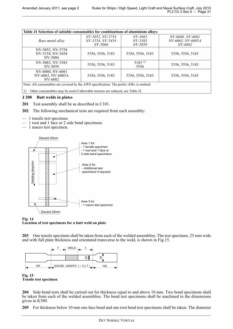
Amended January 2011, see page 2 Rules for Ships / High Speed, Light Craft and Naval Surface Craft, July 2010 Pt.2 Ch.3 Sec.5 – Page 31
J 200 Butt welds in plates201 Test assembly shall be as described in C101.202 The following mechanical tests are required from each assembly:
— 1 tensile test specimen— 1 root and 1 face or 2 side bend specimens— 1 macro test specimen.
Fig. 14Location of test specimens for a butt weld on plate
203 One tensile specimen shall be taken from each of the welded assemblies. The test specimen, 25 mm wideand with full plate thickness and orientated transverse to the weld, is shown in Fig.15.
Fig. 15Tensile test specimen
204 Side-bend tests shall be carried out for thickness equal to and above 10 mm. Two bend specimens shallbe taken from each of the welded assemblies. The bend test specimens shall be machined to the dimensionsgiven in K300.205 For thickness below 10 mm one face bend and one root bend test specimens shall be taken. The diameter
Table J1 Selection of suitable consumables for combinations of aluminium alloys
Base metal alloy NV-5052, NV-5754NV-5154, NV-5454
NV-5086
NV-5083NV-5383 NV-5059
NV-6060, NV-6061NV-6063, NV-6005A
NV-6082 NV-5052, NV-5754NV-5154, NV-5454
NV-50865356, 5556, 5183 5356, 5556, 5183 5356, 5556, 5183
NV-5083, NV-5383NV-5059 5356, 5556, 5183 5183 1)
5556 5356, 5556, 5183
NV-6060, NV-6061NV-6063, NV-6005A
NV-60825356, 5556, 5183 5356, 5556, 5183 5356, 5556, 5183
Note: All consumables are covered by the AWS specification. The prefix «ER» is omitted.
1) Other consumables may be used if allowable stresses are reduced, see Table J2.
Area 1 for:- 1 tensile specimen- 1 root and 1 face or2 side bend specimens
Area 2 for:- Additional testspecimens if required
Area 3 for:- 1 macro test specimen
Discard 25mm
Discard 25mm
Wel
ding
dire
ctio
n
T WELD T
25 35
100 GAUGE LENGTH ( ~ 3 x T ) 100
DET NORSKE VERITAS

Rules for Ships / High Speed, Light Craft and Naval Surface Craft, July 2010 Amended January 2011, see page 2Pt.2 Ch.3 Sec.5 – Page 32
of the bending mandrel shall be as given in J702. 206 One macrosection shall be prepared from the test assembly to reveal the weldment macro structure. Themacrosection shall be visually inspected using a magnification of 5 to 10X.
J 300 Butt welds in pipes301 Test assembly shall be as described in C201.302 The following mechanical tests are required from each assembly:
— 1 tensile test specimen— 1 root and 1 face or 2 side bend specimens— 1 macro test specimen.
Fig. 16Location of test specimens for a butt weld in pipe
303 One tensile specimen shall be taken from each of the welded assemblies. The test specimen, 25 mm wideand with full plate thickness and orientated transverse to the weld, is shown in Fig.15.304 Side-bend tests shall be carried out for thickness equal to and above 10 mm. Two bend specimens shallbe taken from each of the welded assemblies. The bend test specimens shall be machined to the dimensionsgiven in K300.305 For thickness below 10 mm one face bend and one root bend test specimens shall be taken. The diameterof the bending mandrel shall be as given in J702. 306 One macrosection shall be prepared from the test assembly to reveal the weldment macro structure. Themacrosection shall be visually inspected using a magnification of 5 to 10X.
J 400 Branch connections401 The following mechanical tests are required from each assembly (see Fig.7):
— two macrosection tests at 12 and 6 o'clock.
J 500 Fillet welds501 Test assembly shall be as described in C501.502 The following tests shall be performed:
— two macrosection tests. One of the macrosections shall be taken at the marked position of the stop/restart.The macrosection shall include about 10 mm of unaffected base material and shall be prepared and etchedon one side to clearly reveal the fusion line and the HAZ.
J 600 Non destructive testing of test assemblies601 Non destructive testing shall be according to D100 for butt welds and D200 for fillet welds and partialpenetration welds.
Area 2 for:- 1 tensile specimen- 1 root and 1 face or2 side bend specimens
Area 1 for:- Additional testspecimens if required
Top for fixed pipe
DET NORSKE VERITAS

Amended January 2011, see page 2 Rules for Ships / High Speed, Light Craft and Naval Surface Craft, July 2010 Pt.2 Ch.3 Sec.5 – Page 33
J 700 Destructive testing 701 The tensile strength of the test specimens shall not be less than specified for the parent alloy in Table J2.
702 The bend test specimens shall be bent on a mandrel with maximum diameter as given in the formulabelow. The bending angle shall be at least 180°. After bending, the test specimens shall not reveal any opendefects in any direction greater than 3 mm. Smaller cracks developing from the edges of the specimens shallnot normally be considered as significant, unless there is definite evidence that they result from inclusions orother defects.«Wrap around» bending as shown in K300 is the preferred bending method.
where
d = maximum former diameterts = thickness of the bend test specimen (this includes side bends)A = minimum tensile elongation required by the material specification (for combination between different
alloys, the lowest individual value shall be used).703 The macrosections shall show a regular weld profile with smooth transitions to the base materials andwithout significant or excessive reinforcement. Cracks and lack of fusion are not acceptable.704 When a butt weld is made between two plates of different alloys the tensile strength to be obtained onthe welded assembly shall be in agreement with the requirements relating to the alloy having the lower strength.705 If the WPQT fails to comply with any of the requirements for NDT one extra WPQT shall be welded andsubjected to the same testing. If this additional test does not meet the relevant requirements, the actual WPSshall be considered as not qualified and a re-specification of the WPS shall be made prior to a new qualificationtest.
J 800 Range of qualification801 The validity of approved welding procedure shall be as given in F100.802 A qualified welding procedure shall be used within the ranges of the parameters below.Base materialThe following changes shall lead to a new qualification:
Table J2 Mechanical properties in the welded condition
Alloy Temper Filler Tensile strength
Rm minimum(N/mm2)
NV-5052 0, H111,H32, H34 5356 170
NV-5754 0, H111, H24 5356-5183 190
NV-5154A 0, H111H32, H34 5356-5183 215
NV-5454 0, H111, H32, H34, 5356-5183 215
NV-5086 0, H111, H112H116, H321, H34 5356-5183 240
NV-50830, H111, H112 t < 6 mm0, H111, H112 t > 6mm
H116, H321H116, H321
51835356-5183
53565183
270270270270
NV-5383 0, H111,H116, H321 5183 290
NV-5059 0, H111,H116, H321 5183 330
NV-6060 T4, T5, T6 5356-5183 95
NV-6061 T4T5 or T6 5356-5183 165
165
NV-6063 T4, T5T6 5356-5183 100
100NV-6005A T4, T5 or T6 5356-5183 165
NV-6082 T4T5 or T6 5356-5183 170
170
d100ts
A------------- ts–=
DET NORSKE VERITAS

Rules for Ships / High Speed, Light Craft and Naval Surface Craft, July 2010 Amended January 2011, see page 2Pt.2 Ch.3 Sec.5 – Page 34
a) In general, significant change of material properties which will obviously affect the weldability andmechanical properties.
b) More specifically, aluminium alloys are grouped in the following categories:
i) NV-5052, NV-5754A, NV-5154, NV-5454ii) NV-5086, NV-5083, NV-5383, NV-5059iii) NV-6060, NV-6061, NV6063, NV-6005A, NV-6082.
The qualification on aluminium alloys in category iii) will qualify for the alloys in category ii) and category i)but not vice versa. The qualification on aluminium alloys in category ii) will qualify for the alloys in categoryi) but not vice versa. ThicknessThickness, t, is defined as follows:
a) For a butt weld: The base metal thickness, which for welds between dissimilar thicknesses is that of thethinner material.
b) For a fillet weld: The base metal thickness, which for welds between dissimilar thicknesses is that of thethicker material. However, for each thickness range qualified, as in Table B2 there is an associated rangeof qualified throat thickness as given below.
c) For a set-on branch connection: The thickness of the branch pipe.d) For a set-in or set-through branch connection: The thickness of the main pipe.e) For a T-butt joint in plate: The thickness of the prepared plate.
The requirements to qualified thickness range for butt welds shall be as given in Table J3.
In addition to the requirements of Table J3, the range of qualification of the throat thickness “a” of fillet weldsis given in Table J4.
Where a fillet weld is qualified by means of a butt weld test, the throat thickness range qualified shall be basedon the thickness of the deposited weld metal.Diameter of pipes and branch connectionsThe qualification of a welding procedure test on diameter D shall include qualification for diameters in thefollowing ranges as given in Table J5.
Angle of branch connectionsA WPQT carried out on a branch connection with angle α shall qualify all branch connection angles in therange of α to 90°.
Table J3 Qualified thickness range Thickness
t (mm) of test piece
Qualification range
t < 3 0.5 t to 2 t3 ≤ t ≤ 20 3 to 2 t
t > 20 ≥ 0.8 t
Table J4 Range of qualification for the throat thickness for plates and pipes
Throat thickness of the test piece a Range of qualification
a < 10 0.75 a to 1.5 a a ≥ 10 ≥ 7.5
Table J5 Qualified range for pipe and branch connection diametersDiameter of the test
piece D (mm) 1)
Qualification range
D ≤ 25 0.5 D to 2 DD > 25 ≥ 0.5 D and plates
1) D is the outside diameter of the pipe or outside diameter of the branch pipe.
DET NORSKE VERITAS

Amended January 2011, see page 2 Rules for Ships / High Speed, Light Craft and Naval Surface Craft, July 2010 Pt.2 Ch.3 Sec.5 – Page 35
Welding consumablesThe following changes shall lead to a new qualification:
— any change in consumable classification— any significant change of shielding gas mixture.
Welding positionsThe following changes shall lead to a new qualification:
— change from one principal welding position (see figures in F200) to another, unless complying withTable J6.
Type of jointThe following changes shall lead to a new qualification:
— change from fillet weld to butt weld— change from two sided welding to one side, but not vice versa— deletion of back gouging— deletion of backing— change from butt joint in plates to butt joints in pipes with outside diameter less than 500mm.— any change of groove dimensions specified in the WPS.
Welding conditionThe following changes shall lead to a new qualification:
— any change of welding process— change from spray arc to short arc or pulsed arc or vice versa— change in heat input beyond ±25% — any decrease in preheat temperature— higher interpass temperature than that used in the qualification test— change of heat treatment used in the qualification test. Holding time may be adjusted as a function of
thickness — change from weaving to stringer bead technique or vice versa— change from multi-pass welding to one-pass welding— change in welding current from A.C. to D.C. or vice versa, or change in polarity. If recommended by the
consumable manufacturer particular exemption may be given for SMAW in change from A.C. to D.C.
J 900 Retesting901 If the WPQT fails to comply with any of the requirements for NDT one extra WPQT shall be welded andsubjected to the same testing. If this additional test does not meet the relevant requirements, the actual WPSshall be considered as not qualified and a re-specification of the WPS shall be made prior to a new qualificationtest. If the result of any destructive test fails to meet the requirements, two further tests may be made from the samewelded joint if there is sufficient material available. If not, a new assembly shall be welded using the same
Table J6 Qualified principal positions for butt welds and fillet welds, aluminium
Test weldJoint
configuration 1)2)Principal positions
Qualified positions 3)
Butt welds Fillet weldsplates or pipes
Plates Pipes
Butt welds in plates1G2G3G4G
1G1G, 2G, 3G1G, 2G, 3G
All
1G 1F1F, 2F, 3F1F, 2F, 3F
All
Butt welds in pipes1G2G5G
1G1G, 2G, 3G
All
1G2G
1G, 5G
1F1F, 2F, 4F
All
Fillet welds
1F2F3F4F5F
1F1F, 2F, 3F1F, 2F, 3F
AllAll
1) Pipes with D > 500 mm are considered equivalent to plates (apply only to the main pipe in branch connections).2) Branch connections shall be qualified separately. 3) The vertical downwards position shall be qualified separately.
DET NORSKE VERITAS

Rules for Ships / High Speed, Light Craft and Naval Surface Craft, July 2010 Amended January 2011, see page 2Pt.2 Ch.3 Sec.5 – Page 36
WPS. If either of these additional test specimens does not comply with the relevant requirements, the WPS shallbe regarded as not capable of complying with the requirements without modification.
K. TestingK 100 General101 Testing of welds shall be carried out as specified in 200 to 300. Reference is also made to relevantparagraphs in Ch.1 Sec.2.
K 200 Tensile testing at ambient temperature201 For tensile testing of all-weld-metal and butt welds two different types of test specimens may be used,round test specimens or flat test specimens (see Fig.17) as described below.
a) Deposited metal tensile test Normally, round test specimens with the following dimensions shall be used:
d = 10 mmLo = 50 mmLc = 60 mmR ≥ 5 mm
b) Butt weld tensile test Flat test specimens with the weld machined flush with the surface of the plate, shall be used. Thedimensions shall be as follows:
a = thickness of plate, tb = 25 mmL0 = Lc = 3t or 2t + width of weld, whichever is the greatestR = 25 mm.
Fig. 17Tensile test specimen.
K 300 Bend testing301 Flat bend test specimens, as given in Fig.18 shall be used. Edges on tension side to be rounded to a radiusof 1 to 2mm.
DET NORSKE VERITAS

Amended January 2011, see page 2 Rules for Ships / High Speed, Light Craft and Naval Surface Craft, July 2010 Pt.2 Ch.3 Sec.5 – Page 37
Fig. 18Bend test specimen.
Fig. 19Wrap around bend test.
302 When the wrap around bend test, exemplified in Fig.19 is used, e.g. for the side bend test of a weld, thelength of the test specimen has to be greater than the length 11a shown in Fig.18.303 For butt weld bend test specimens, the weld shall be machined flush with the surface of the plate.304 For transverse face-bend and root-bend test specimens for butt weld test the dimensions shall be asfollows:
a = as rolled thickness t of the plateb = 30 mm.If the as rolled thickness t is greater than 25 mm, it may be reduced to 25 mm by machining on the compressionside of the test specimen.305 For transverse side-bend test specimens for butt weld test the dimensions shall be as follows:
a = 10 mmb = as rolled thickness t of the plate.If t ≥ 40 mm, the side-bend test specimen may be subdivided, each part being at least 20 mm wide.306 When a longitudinal face-bend or root-bend weld test is required, a test specimen according to anappropriate standard will be accepted.
DET NORSKE VERITAS

Rules for Ships / High Speed, Light Craft and Naval Surface Craft, July 2010 Amended January 2011, see page 2Pt.2 Ch.3 Sec.6 – Page 38
SECTION 6 FABRICATION AND TOLERANCES
A. GeneralA 100 Application101 This section specifies general requirements for steel fabrication processes, including essential variables,which shall be maintained and controlled by the builders.
B. Material IdentificationB 100 General101 A material identification system which ensures correct installation and documentation of the materialgrades shall be established.
C. Approval of Shop PrimersC 100 General101 Shop primer applied over areas, which will subsequently be welded, shall be of approved type as havingno detrimental effect on the finished weld.
Guidance note:Type approved shop primers are listed under “Non-Metallic Materials (K)” in the DNV register of approved productsand manufacturers, available on the DNV Internet site.
---e-n-d---of---G-u-i-d-a-n-c-e---n-o-t-e---
102 Approved shop primers or thin coatings of linseed oil may be applied to welds subject to tightness testin agreement with the manufacturer’s recommendation. In general the applied film thickness on welds shall notexceed 50 microns.
D. Welding EnvironmentD 100 General101 Welding work shall not be carried out in environmental conditions that may have a detrimental effectsuch as wind, damp and cold.102 Welding processes sensitive to draughts shall be adequately protected.103 The grooves shall by dry at all time of welding.104 Preheating temperature, whenever required, shall in any case be within the limit of essential variables,see E306. 105 The welding interpass temperature shall not drop below the minimum required preheating temperature.
E. Cutting, Forming, Assembly and WeldingE 100 Cutting101 Cut edges are to be accurate and uniform in order to provide a shape compatible with the weld jointdesign.102 Deviation of cut edges shall generally be within the standard specified by IACS REC No.47 Shipbuildingand Repair Quality Standard Part A.103 Attention shall be paid to avoid excessive local hardening and carbon contaminations by thermal cutting. 104 The effect of work hardening and risk of cracked edges shall be considered if shearing is used for cuttingof material.105 Correction by welding as compensation for improper cutting shall be in accordance with procedures for
DET NORSKE VERITAS

Amended January 2011, see page 2 Rules for Ships / High Speed, Light Craft and Naval Surface Craft, July 2010 Pt.2 Ch.3 Sec.6 – Page 39
repairs.
E 200 Forming201 Forming and straightening of materials shall be performed according to procedures which outline thesuccession of the controlled steps.202 The degree of cold forming for steels in structural members shall be carried out within the deformationrange recommended by the manufacturer. Should however such documentation not be available, thedeformation rate for carbon manganese steels shall be less than 10%, respectively 20% for austenitic andferritic-austenitic steels. If the deformation exceeds 10%, respectively 20% either heat treatment or strainageing test shall be carried out in accordance with an agreed procedure as stipulated in Pt.3 Ch.1 Sec.3 C1100(Rules for Classification of Ships).
Guidance note:The plastic deformation e may be calculated by the following simplified formulae:Single-curvature deformationCold rolling or pressing of plates to cylindrical forms:e = (t/2Rc+t) × 100%Cold bending of straight pipes to bends:e = (D/2Rc) × 100%Double curvature deformationForming of plates to spheres:e = (t(1 + ν)/2Rc) × 100%
t = material thicknessD = outside diameter of pipe of vesselRc = forming radiusν = Poisson’s ratio (0.5 for plastic condition).
---e-n-d---of---G-u-i-d-a-n-c-e---n-o-t-e---
203 Forming of steels at high temperatures shall be effectuated with due regard to adverse effects of thematerial’s properties. Forming of steels above 650ºC shall be subject to agreement with the Society.
E 300 Assembly and Welding 301 Members to be welded shall be brought into correct alignment and held in position by clamps, tack welds,or other suitable devices, until welding has been completed or progressed to a stage where in control of theprocess. Such arrangement shall be suitably arranged to minimise distortion and built-in stresses.302 Fit-up shall be checked for dimensional accuracy before welding. Special attention shall be drawn toassure correct fit-up of areas, of which direct visual inspection is impossible. 303 Surfaces to be welded shall be free from mill scale, slag, rust, paint or other contaminating substances.304 Grooves shall be within the groove profile particulars given by the welding procedure specification(WPS). Grooves shall be slag free.305 All welding, including tack welding, seal welding, welding of lifting lugs and repair welding, shall beperformed within the limits of essential variables of the welding procedure specification (WPS).
DET NORSKE VERITAS

Rules for Ships / High Speed, Light Craft and Naval Surface Craft, July 2010 Amended January 2011, see page 2Pt.2 Ch.3 Sec.6 – Page 40
306 Preheating, when required, shall be applied in accordance with agreed procedures. Special attention shallbe paid to temperature control during the welding process such that the preheat temperature is kept uniformlyin affected part of the welded object.
Guidance note:Normal strength steels may require preheating depending on the combined plate thicknesses and the degree of jointrestraint.Preheating is normally required for welding of high and extra high strength steels depending on chemicalcomposition, rolling process, joint restraint and combined plate thickness. Post heating may additionally be requiredfor extra high strength steels.
---e-n-d---of---G-u-i-d-a-n-c-e---n-o-t-e---
307 The welding sequence shall be such that the amount of shrinkage, distortions and residual stresses areminimised.
308 Welds shall be terminated in a manner such that all welds are sound and without end craters. Run-offplates shall be used, where practicable, and be removed upon completion and cooling of the weld. Cut weldsshall be made smooth and flush with the edges of the abutting parts.
309 Tack welding shall be carried out in accordance with approved welding procedure specifications (WPS),specifying the applied minimum welding length.
310 Tack welds used for assembly shall be removed before welding leaving the effected area free fromdefects.
311 Tack welds, if retained as part of the welding process, shall be free from defects and provide adequateconditions for pass welding.
312 Storage and handling of welding consumables shall be in accordance with the manufacturer’srecommendations, and in accordance with procedures giving details regarding conditions in storage rooms,temperature in storage ovens and quivers, length of exposure and conditions, as applicable.
313 Consumables which have been contaminated by moisture, rust, oil, grease, dirt or other deleteriousmatters, shall be discarded unless properly reconditioned.
314 Recycling of fluxes for submerged arc welding (SAW) shall be performed in a manner that ensures amixture of new and used flux with continually homogenous properties.
F. Repairs
F 100 General
101 Guidance to general welding repair work is given in IACS REC No.47 Shipbuilding and Repair QualityStandard Part A.
102 Defects in welds may be repaired by grinding, machining and/or welding. In order to verify completeremoval of defects, effected areas shall be examined with suitable NDT methods.
F 200 Repair welding
201 Repairs by welding shall be carried out in accordance with approved welding procedure specifications(WPS). Mechanical properties shall satisfy the minimum specified properties of the material in question.
202 Defects shall be completely removed before necessary repairs are carried out. Repairs with arc-airgouging shall be followed by grinding.
203 Repair welding in the same area may be carried out twice. Further repairs shall be subject to agreementwith the Society.
204 All weld repairs shall at least be re-inspected with the same NDT methods as originally applied.
F 300 Flame straightening
301 Members distorted by welding may be straightened by mechanical means or by a limited amount oflocalised heat. Flame straightening shall be done in accordance with an agreed procedure.
302 Corrective measures relating to flame straightening shall be carried out with due regard to possibledegradation of the material properties. Reference is made to IACS REC No.47 Shipbuilding and Repair QualityStandard Part A Table 6.5 regarding max. temperature on the surface.
DET NORSKE VERITAS

Amended January 2011, see page 2 Rules for Ships / High Speed, Light Craft and Naval Surface Craft, July 2010 Pt.2 Ch.3 Sec.6 – Page 41
G. Inspection and TolerancesG 100 General101 Inspection shall be carried out in accordance with inspection and test plans to confirm that work is carriedout in accordance with established project procedures and plans such that all project requirements are compliedwith to the satisfaction of the Society. Reference is given to IACS UR Z23 regarding survey of hull structure.102 Due consideration shall be given to the access and the time required for adequate inspection duringfabrication.103 High non-conformance rates in execution of the work or in the product itself shall call for specialconsiderations in agreement with the Society. Such special considerations may include, but not be limited to,increased inspection, re-qualification of personnel or other agreed remedial actions.
G 200 Alignment and straightness201 Allowable acceptable alignment shall be established depending on the criticality of the design. Specialrequirements relating to special type and service are given in Pt.5.202 In general fabrication tolerances shall be in compliance with IACS REC No.47 Shipbuilding and RepairQuality Standard, Part A.
G 300 Weld production test requirements301 The Society may require weld production tests to be carried out. The extent and type of testing shall beagreed with the Society.302 When production weld tests are required the test assembly and test requirements shall comply with therelevant requirements of Sec.5.303 If the achieved test results do not comply with the requirements of Sec.5, the results may be submitted forconsideration. The production weld test may be accepted subject to acceptable results from additional testprescribed by the Society.
DET NORSKE VERITAS

Rules for Ships / High Speed, Light Craft and Naval Surface Craft, July 2010 Amended January 2011, see page 2Pt.2 Ch.3 Sec.7 – Page 42
SECTION 7 NON DESTRUCTIVE TESTING OF WELDS
A. GeneralA 100 Application101 This section provides requirements for quality control of ship hull welds during newbuilding. The sectioncontains requirements for the application of non-destructive testing (NDT) - methods, extent of testing andrequired quality level for satisfactory workmanship.102 Additional requirements to extent of testing and acceptance criteria are given in Pt.5 for the relevant shiptypes.
A 200 Basic requirements201 The rules are based on the following conditions mentioned below.Weld joint typesThe following main weld joints are covered (see figures in Sec.5):
— butt joints — T-joints (with and without full penetration)— fillet welds.
Types of imperfections The main types of imperfections in fusion welding are given in EN ISO 6520-1 “Welding and Allied Processes– Classification of Geometric Imperfections in Metallic materials, Part 1: Fusion Welding”. Testing methods
— For detection of surface imperfections the following methods applies: Visual testing (VT), Magneticparticle testing (MT) and Penetrant testing (PT).
— For detection of sub-surface imperfections the following methods applies: Ultrasonic testing (UT) andRadiographic testing (RT).
The choice of test methods to be applied in each case depends on the component- or weld shape, the materialand the defects to be detected. 202 For NV 420 grades and higher, final inspection and NDT shall not be carried out before 48 hours aftercompletion unless heat treatment has been carried out.
B. NDT ProceduresB 100 General101 NDT shall be performed in accordance with agreed written procedures that, as a minimum are inaccordance with DNV Classification Notes No.7 and give detailed information on the following aspects:
— applicable code or standard— materials, dimensions and temperature of tested material— periodically verification of equipment requirements— joint configuration and dimensions— technique (sketches/ figures to be referenced in the NDT report)— equipment and consumables— sensitivity, and light conditions for MT and PT— calibration techniques and calibration references— testing parameters and variables— assessment of imperfections and the surfaces from which the examination has been performed— reporting and documentation of results. The reporting system shall ensure that there is no doubt what is
examined, where it is examined and give a clear and exact description of reportable defect location.— reference to applicable welding procedure(s)— personnel qualification— acceptance criteria.
102 Unless otherwise agreed, the surface to be tested shall be presented clean and smooth, i.e. free from dirt,scale, rust, welding spatter, etc. which may influence the results of the testing.
DET NORSKE VERITAS

Amended January 2011, see page 2 Rules for Ships / High Speed, Light Craft and Naval Surface Craft, July 2010 Pt.2 Ch.3 Sec.7 – Page 43
B 200 Visual testing201 If necessary mechanical aids (gauges and rulers) should be used to assess and size the discontinuities.Unless otherwise agreed, visual testing shall be completed before other NDT methods are applied.
B 300 Magnetic particle testing301 Where possible, both sides of the welds shall be tested. Magnetic particle testing shall be applied forwelds in furrow-magnetic materials if not otherwise agreed.
B 400 Radiographic testing401 For radiographic inspection, X-ray source shall be used whenever possible. Gamma-ray sources may beused as outlined in Classification Note No.7. Radiographic testing may be replaced by ultrasonic testing andvice versa, when methodologically justifiable and in agreement with the Society. 402 Processing and storage shall be such that the radiographs maintain their quality throughout the agreedstorage time. The radiographs shall be free from imperfections due to development processing. 403 Suspect planar indications discovered by radiographic testing that is left un-repaired shall be typedetermined, located and sized by ultrasonic testing.
B 500 Ultrasonic testing501 Ultrasonic test procedures shall contain sketches for each type of joint and dimensional range of jointswhich clearly show scanning pattern and probes to be used. Ultrasonic examination shall not be carried out on welds with thickness < 10 mm if not qualified and accepteddown to 8 mm.Ultrasonic testing of welds shall include testing of the area adjacent to the weld for laminations and scanningfor transverse defects in the weld and base material.
B 600 Penetrant testing601 Where possible, both sides of the welds shall be tested. Penetrant testing shall only be applied for weldsin non-furrow magnetic materials if not otherwise agreed.
C. Personnel QualificationsC 100 General101 All testing shall be carried out by qualified and certified personnel. The NDT operators shall be certifiedaccording to a recognized certification scheme accepted by the Society, e.g. EN 473, ISO 9712. The certificateshall clearly state the qualifications as to which testing method and within which category the operator iscertified to.
D. Extent of NDTD 100 General101 The extent of testing will depend on the type of ship and the location of the joints. 102 The basic requirements for all ship types are that all welds are subject to 100% visual testing. In addition,welds shall be subjected to testing with other test methods as given in the table below. The extent may beextended further depending on quality of welds and repair rate (ref. E201).103 The locations and areas to be examined shall be incorporated into the NDT plan.
DET NORSKE VERITAS

Rules for Ships / High Speed, Light Craft and Naval Surface Craft, July 2010 Amended January 2011, see page 2Pt.2 Ch.3 Sec.7 – Page 44
104 The different areas in Table D1 are defined as follow:Critical areasAreas in way of critical load transfer points and large stress concentrations where a failure will endanger thesafety of the ship, such as:
— stress concentrations in rudders or intersection between rudder structure and hull— for twin hull vessels stress concentrations in way of connections between hull and wet deck— deck beams in open hatch container ships— strength deck plating at outboard corners of cargo hatch openings in container carriers and other ships with
similar hatch opening configuration— other areas where the likelihood of occurrence of detrimental defects is considered to be extra high.
Guidance note:Areas to be considered for classification under this item are:- welds produced by welding methods which the yard has little or no user experience- welds produced by high heat input (>5 kJ/mm) welding methods- welds in large thickness (>50mm).
---e-n-d---of---G-u-i-d-a-n-c-e---n-o-t-e---
Deck and bottom plating within 0.4L amidship
— Sheer strake at strength deck. — Stringer plate in strength deck. — Deck strake at longitudinal bulkhead. — Strength deck plating at corners of cargo hatch openings in bulk carriers, ore carriers, combination carriers
and other ships with similar hatch opening configuration. — Bilge strake.— Longitudinal hatch coamings of length greater than 0.15 L.— End brackets and deck house transition of longitudinal cargo hatch coamings.— All watertight bulkheads independent of location.
Guidance note:For ships with no clearly defined strength deck e.g. cruise ships, the above extents shall be applied to the deckscontributing most to the hull strength
---e-n-d---of---G-u-i-d-a-n-c-e---n-o-t-e---
GeneralAreas not mentioned above.105 NDT shall cover start and stop points of automatically welded seams.
E. Acceptance Criteria for NDTE 100 General101 All welds shall show evidence of good workmanship. For visual inspection IACS REC No.47“Shipbuilding and Repair Quality Standard Part A” may be applied. Acceptance criteria for NDT shallnormally comply with ISO 5817 quality level C, intermediate. For critical areas more stringent requirementssuch as ISO 5817 level B, may be applied. Level B and level C of ISO 5817 are equal to, respectively,
Table D1 Minimum extent (in%) of NDT for structural welds
Area Type of connection Testing methodMT/PT1) RT/UT2)
GeneralButt- and T-Joints, full penetration
T-joints, partly penetrationFillet welds
2%2%
-
2%--
Deck/bottom plating within 0.4 L amidship
Butt- and T-Joints, full penetrationT-joints, partly penetration
Fillet welds
5%5%
-
5%--
Critical areasButt- and T-Joints, full penetration
T-joints, partly penetrationFillet welds
20%20%20%
20%--
1) Magnetic particle testing shall be applied for furrow-magnetic materials.2) Radiographic testing shall not be applied for T-joints.
DET NORSKE VERITAS

Amended January 2011, see page 2 Rules for Ships / High Speed, Light Craft and Naval Surface Craft, July 2010 Pt.2 Ch.3 Sec.7 – Page 45
acceptance level 2 and 3 of EN 1712/ISO 11666 “Non-destructive examination of welds. Ultrasonicexamination of welded joints - acceptance levels” (ref. correlation given in EN 1712/ISO 11666 and EN 12062/ISO 17635).Regarding ultrasonic testing EN 1712/ISO 11666 level 2 or level 3 applies with the following amendment: Allimperfections from which the reflected echo amplitude exceeds the evaluation level shall be characterised, andall that are characterised as planar e.g. cracks, lack of fusion, incomplete penetration shall be rejected. Welds tested and accepted by the builder may be verified if deemed necessary by the Society.
E 200 Non-conforming weldments 201 If a non-conforming discontinuity is detected the lengths welded immediately before and after the sectioncontaining the discontinuity shall be examined by the same method. If systematically repeated discontinuitiesare revealed, the extent of testing shall be increased for welds manufactured under same conditions and wheresimilar defects may be expected.202 If non-conforming discontinuities are found to occur regularly, the welding procedures shall bereassessed before continuation of the welding, and necessary actions shall be taken to bring the production tothe required quality level.203 Detected non-conforming discontinuities shall be repaired unless they are found acceptable by theSociety. Removal of weld discontinuities and repair shall be performed in accordance with a procedureapproved by the Society.204 After repair welding has been performed, the complete weld, (i.e. the repaired area plus at least 100 mmon each side) shall be subjected to at least to the same NDT method(s) as specified for the original weld.
DET NORSKE VERITAS

Rules for Ships / High Speed, Light Craft and Naval Surface Craft, July 2010 Amended January 2011, see page 2Pt.2 Ch.3 Sec.8 – Page 46
SECTION 8 STRUCTURAL AND TIGHTNESS TESTING
A. General
A 100 Application
101 This section specifies general requirements to structural and tightness testing of tanks and holds.
102 For Tanker for Liquefied Gas additional requirements are given in Pt.5 Ch.5 (Rules for Classification ofShips).
B. Testing
B 100 Definitions
101 The following terms are used in B:Structural testing is a hydrostatic test, carried out in order to demonstrate the tightness of the tanks and thestructural adequacy of the design. Where hydrostatic testing is not practically feasible, hydropneumatic testingmay be carried out instead under provision that the test is simulating, as far as practicable, the actual loadingof the tank. Apart from compulsory structural tests to Tanker for Chemicals ESP, structural tests do not needto be repeated for subsequent vessels in a series of identical newbuildings, unless considered necessary by theSociety.Leak testing is an air or other medium test, carried out in order to demonstrate the tightness of the structure. Hydropneumatic testing is a combination of hydrostatic and air testing, carried out in order to demonstrate thetightness of the tanks and the structural adequacy of the design.Hose testing is a water test carried out to demonstrate tightness of structural items. Shop primer is a thin coating applied after surface preparation and prior to fabrication as a protection againstcorrosion during fabrication.Protective coating is a final coating protecting the structure from corrosion.Watertight means capable of preventing the passage of water through the structure under a head of water forwhich the surrounding structure is designed. Weathertight means that in any sea conditions water will not penetrate into the ship.
B 200 General requirements
201 Structural testing may be carried out after a protective coating has been applied, provided a leak test iscarried out before application of the protective coating. All pipe connections to tanks shall be fitted beforestructural testing. When structural testing at the building berth is undesirable or impossible, structural testing afloat may beaccepted. The structural testing shall be carried out by filling each tank separately to the test head. Examinationof bottom and lower side structures shall be made in empty tanks at the maximum practical attainable draught.
202 Leak testing shall be carried out prior to the protective coating being applied to the welds. Shop primermay be applied to welds. An efficient indicating liquid shall be applied, when air is used as the test medium. The air pressure shall bekept at a maximum pressure of 20 kN/m2 for 1 hr. and shall be reduced to 15 kN/m2 before inspection. Inaddition to an effective means of reading the air pressure, a safety valve, or a reliable equivalent alternative,shall be connected to the compartment being tested. Test pressure shall be verified by means of one master pressure gauge. The Society may accept alternativemeans which are considered to be equivalently reliable.
Guidance note:Silicate based shop primer may be applied to welds before leak testing. The layer of the primer should be maximum50 microns. Other primers of uncertain chemical composition shall be maximum 30 microns.
---e-n-d---of---G-u-i-d-a-n-c-e---n-o-t-e---
203 For hose testing, the hose pressure shall be at least 200 kN/m2 and applied at a maximum distance of 1.5m. The nozzle inside diameter shall be at least 12.0 mm.
DET NORSKE VERITAS

Amended January 2011, see page 2 Rules for Ships / High Speed, Light Craft and Naval Surface Craft, July 2010 Pt.2 Ch.3 Sec.8 – Page 47
B 300 Specific requirements for extent and type of testing301 The requirements in 302 and 303 give conditions for testing for:
— gravity tanks included independent tanks of 5 m3 or more in capacity— watertight or weathertight structures.
302 Leak testing shall be carried out on all weld connections of tank boundaries, pipe penetrations anderection joints on tank boundaries, except for automatic weld joints and FCAW semi automatic full penetrationbutt welds of erection joints.Selected locations of automatic erection welds and pre-erection manual or automatic welds may be required tobe similarly tested taking account of the quality control procedures operating in the shipyard.303 Extent of testing is given in Table B1.
Table B1 Extent of testing Item to be tested Type of testing Structural test pressure Extent of structural testingAll ship types
Tanks containing liquid and the structures forming boundaries of tanks containing liquid
Structural testing
The greater of the following:
— head of water up to top of overflow — 2.4 m head of water above highest
point of tank. For FRP tanks: 1.0 m above highest point of tank
— pressure valve opening pressure
Tank boundary tested from at least one side 1), 2)
Test of aft peak tank to be carried out after the stern tube has been fitted
Fore peak not used as tank Leak testingAfter peak not used as tank Leak testingChain locker (if aft of collision bulkhead) Structural testing Head of water up to top
Double plate rudders Leak testingWatertight doors below freeboard or bulkhead deck and watertight hatch covers
Leak testing Each door and hatch cover 7)
Weathertight doors, hatch covers, and closing appliances
Hose testing
Watertight bulkheads and decks Leak testing 3), 5), 6)
Ballast ducts Structural testing Ballast pump maximum pressureTrunks, tunnels and ventilators Hose testing 6)
Cofferdams Structural testing
The greater of the following:
— head of water up to top of overflow — 2.4 m head of water above highest
point of tank
4)
Independent tanks Structural testing
The greater of the following:
— head of water up to top of overflow — 0.9 m head of water above highest
point of tank — pressure valve opening pressure
Dry bulk cargo carrier
Ballast holds Structural testing
The greater of the following:
— head of water up to top of overflow — 0.9 m head of water above highest
point of tank
1), 2)In the structural testing, a minor amount of water leakage from hatch cover sealing may be allowed
DET NORSKE VERITAS

Rules for Ships / High Speed, Light Craft and Naval Surface Craft, July 2010 Amended January 2011, see page 2Pt.2 Ch.3 Sec.8 – Page 48
Combination carriers (OBOs)
Watertight hatch covers of cargo tanks Structural testing
The greater of the following:
— head of water up to top of overflow — 2.4 m head of water above hatch
coaming — pressure valve opening pressure
At least every second hatch cover, provided that leak testing is carried out for all hatch covers
Chemical carriers
Integral and independent cargo tanks Structural testing
1) Integral and independent tanks with a design pressure of less than 0.7 bar, the greater of the following:
— 2.4 m head of water above the highest point of the tank
— pressure valve opening pressure.
2) Independent tanks with a design pressure exceeding 0.7 bar shall be tested to 1.5 times the pressure valve opening pressure
Tank boundary tested from at least one side 1), 2)
1) Except for cargo space boundaries of Tanker for Chemical ESP, leak or hydropneumatic testing may replace structural testing, provided that at least one tank of each type is structurally tested.
2) Structural testing need not be repeated for subsequent vessels in a series of identical newbuildings, unless surveyors deem the repetition necessary. This relaxation does not apply to cargo space boundaries for vessels with the class notation Tanker for Chemical ESP.
3) When a hose test cannot be performed without possible damage to outfitting (machinery, cables, switchboards, insulation, etc.) already installed, it may be replaced, at the Society's discretion, by a careful visual inspection of all the crossings and welded joints; where necessary, dye penetrant test, leak test or an ultrasonic leak test may be required.
4) Leak or hydropneumatic testing may be accepted under the conditions specified under 301 when, at the Society's discretion, the latter is considered significant in relation to the construction techniques and the welding procedures adopted.
5) Testing main compartments (not tanks for liquids) by filling them with water is not compulsory. When such testing is not carried out, a hose test is compulsory. This test shall be carried out in the most advanced stage of the fitting out of the ship. In any case, a thorough inspection of the watertight bulkheads shall be carried out.
6) After completion, a hose or flooding test shall be applied to watertight decks and a hose test to watertight trunks, tunnels and ventilators.(SOLAS Ch. II-1/16-1.4)
7) Where water tightness of watertight door has not confirmed by prototype test, testing by filling watertight spaces with water is to be carried out. See SOLAS regulation II-1/16.2 and MSC/Circ.1176.
Table B1 Extent of testing (Continued)Item to be tested Type of testing Structural test pressure Extent of structural testing
DET NORSKE VERITAS