Embed Size (px)
Citation preview
1
Fachgesprach – 12
HVAC Pumps
For Project Managers
WTF Philosophy:
If you don’t remember a certain formula,
it 's OK - you can always G o o g l eT h eS h i t .
But bad engineering CONCEPTS can hurt you.
WTF Institute Mission:
Teach correct engineering CONCEPTS to our PEs and PMs.
5/19/2016
2
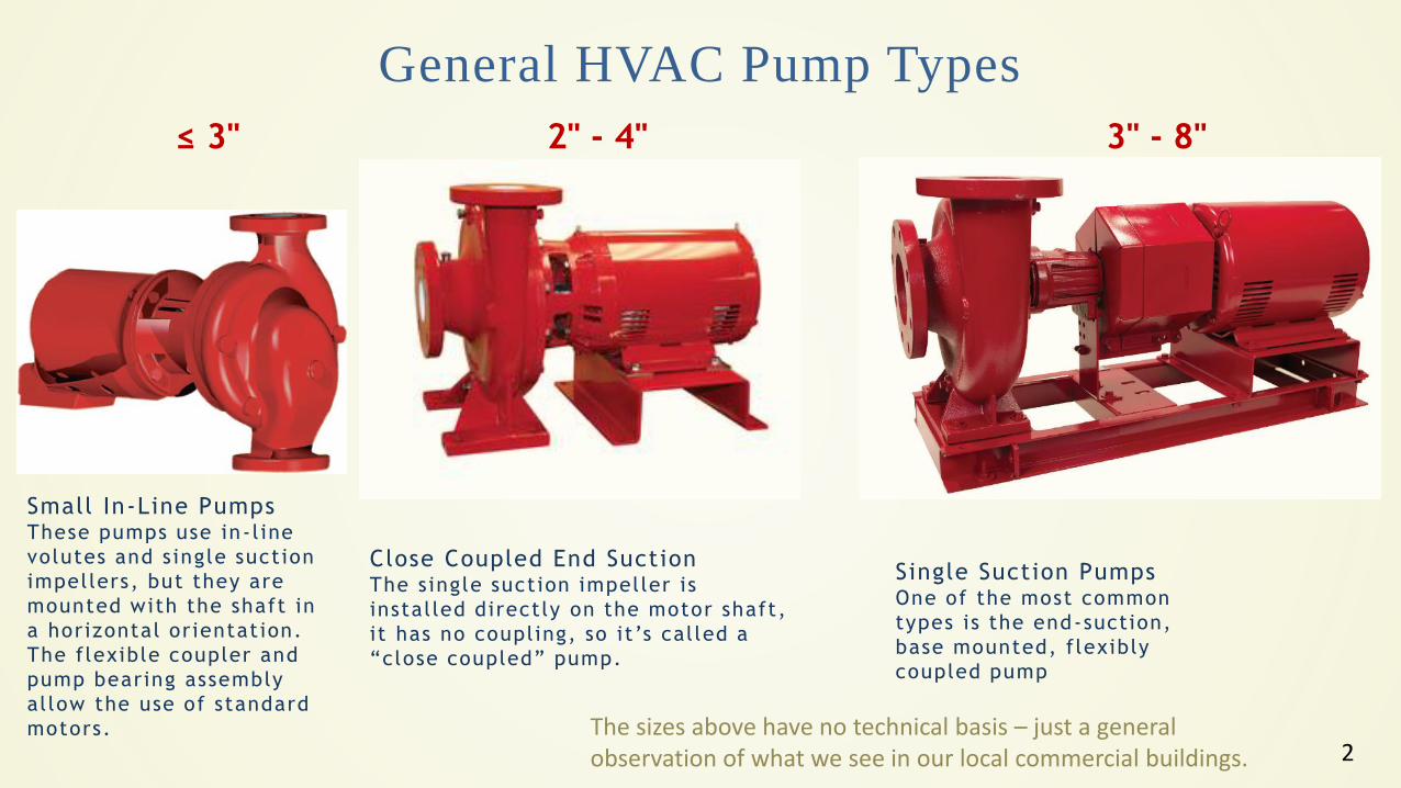
General HVAC Pump Types
≤ 3" 2" - 4" 3" - 8"
Close Coupled End SuctionThe single suction impeller is
instal led directly on the motor shaft,
it has no coupling, so it’s cal led a
“close coupled” pump.
Single Suction PumpsOne of the most common
types is the end-suction,
base mounted, flexibly
coupled pump
Small In-Line PumpsThese pumps use in-l ine
volutes and single suction
impellers, but they are
mounted with the shaft in
a horizontal orientation.
The flexible coupler and
pump bearing assembly
al low the use of standard
motors. The sizes above have no technical basis – just a general observation of what we see in our local commercial buildings.
3
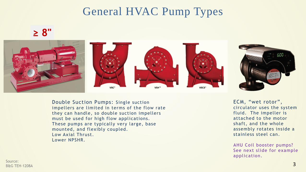
General HVAC Pump Types
≥ 8"
ECM, “wet rotor”,circulator uses the system
fluid. The impeller is
attached to the motor
shaft, and the whole
assembly rotates inside a
stainless steel can.
AHU Coil booster pumps?
See next sl ide for example
appl ication.
Double Suction Pumps: Single suction
impellers are l imited in terms of the flow rate
they can handle, so double suction impellers
must be used for high flow appl ications.
These pumps are typically very large, base
mounted, and flexibly coupled.
Low Axial Thrust.
Lower NPSHR.
Source:
B&G TEH-1208A
4
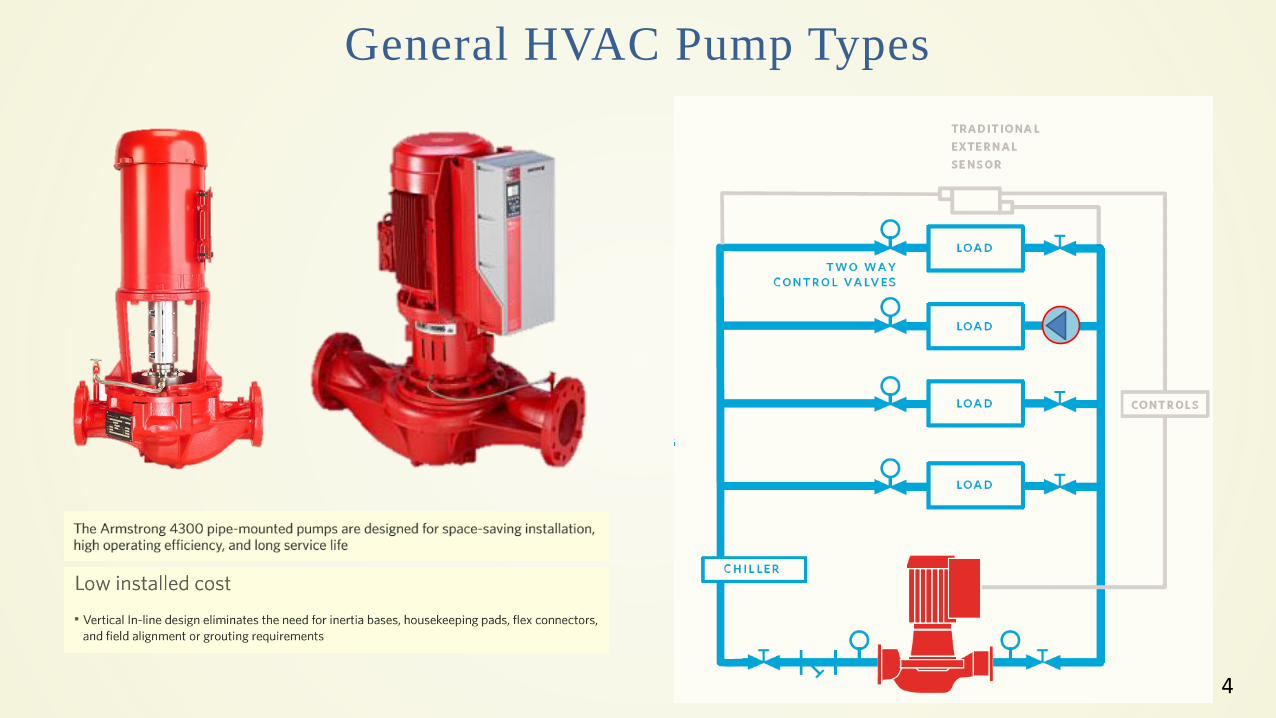
General HVAC Pump Types
5
Pump References
HVAC Pump Handbook, By James Rishel
Highly recommended for HVAC Design Engineers and Project Managers
Pump Handbook, By Igor Karassik
The Bible of the pump community. ( I don’t have i t . )
JMP Co. Videos on Hydronics
CHRIS EDMONDSON
President James M. Pleasants Company, Inc.
Greensboro, NC
Good sol id pract ical stuff.
6
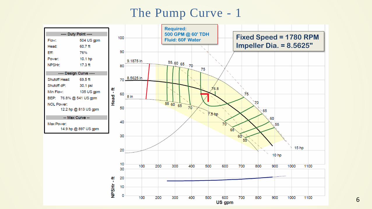
The Pump Curve - 1
Fixed Speed = 1780 RPM
Impeller Dia. = 8.5625"
Required:
500 GPM @ 60' TDH
Fluid: 60F Water
7
Note on the Pumped Fluid
For this presentation the pumped
fluid is water @ 60°F
For glycol, and very high
temperature water, corrections
to the formulas are necessary
8
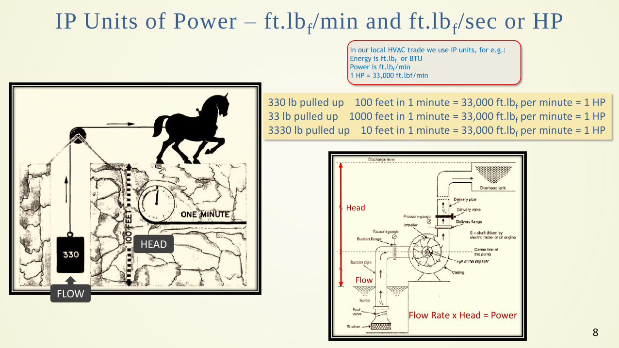
IP Units of Power – ft.lbf/min and ft.lbf/sec or HP
330 lb pulled up 100 feet in 1 minute = 33,000 ft.lbf per minute = 1 HP33 lb pulled up 1000 feet in 1 minute = 33,000 ft.lbf per minute = 1 HP3330 lb pulled up 10 feet in 1 minute = 33,000 ft.lbf per minute = 1 HP
FLOW
HEAD
Flow Rate x Head = Power
Flow
Head
In our local HVAC trade we use IP units, for e.g.:
Energy is ft.lbf or BTU
Power is ft.lbf/min
1 HP = 33,000 ft.lbf/min
9
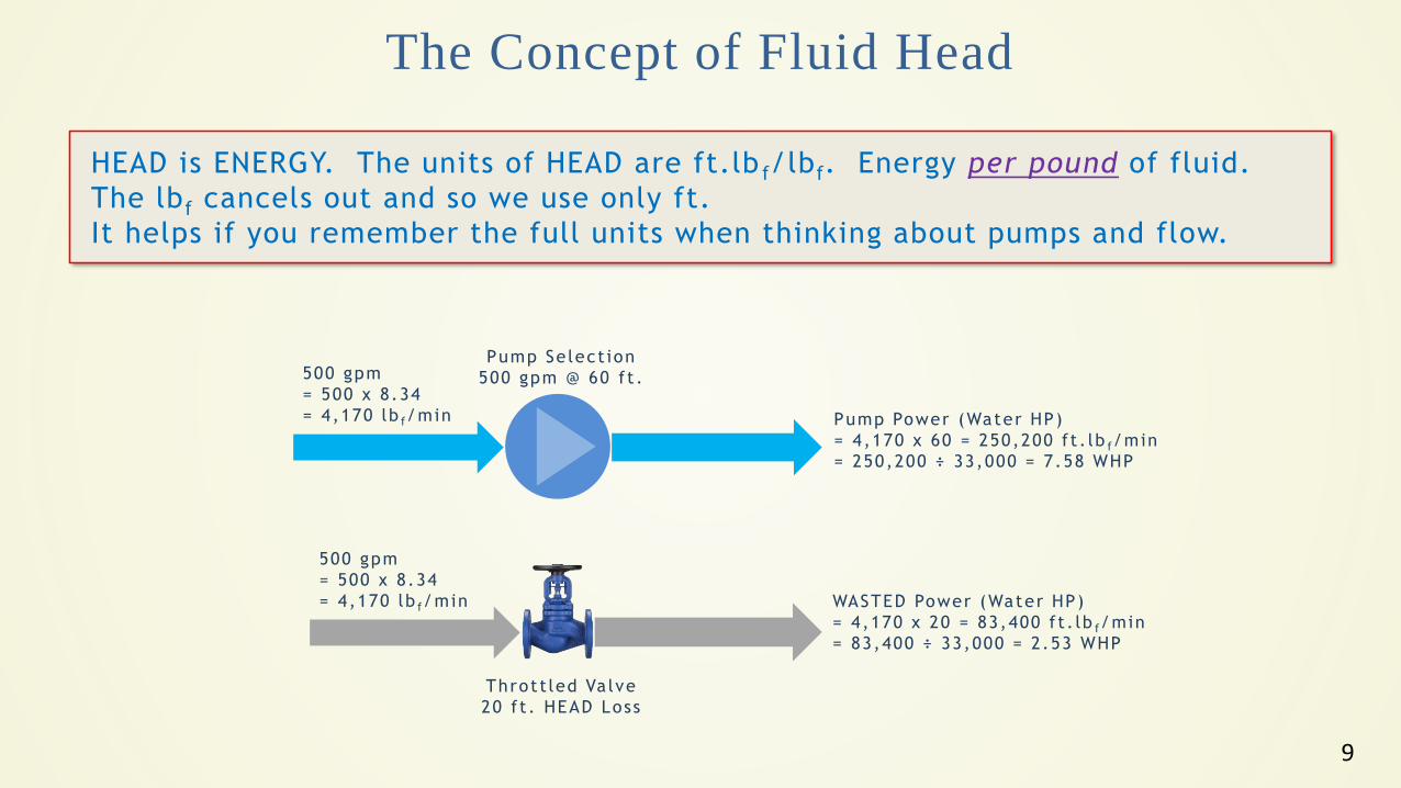
The Concept of Fluid Head
HEAD is ENERGY. The units of HEAD are ft.lb f/lbf. Energy per pound of fluid.
The lbf cancels out and so we use only ft.
It helps if you remember the full units when thinking about pumps and flow.
500 gpm
= 500 x 8.34
= 4,170 lb f/min
Pump Se lect ion
500 gpm @ 60 f t .
Pump Power (Water HP)
= 4,170 x 60 = 250,200 f t . lb f/min
= 250,200 ÷ 33,000 = 7.58 WHP
500 gpm
= 500 x 8.34
= 4,170 lb f/min
Thrott led Va lve
20 f t . HEAD Loss
WASTED Power (Water HP)
= 4,170 x 20 = 83,400 f t . lb f/min
= 83,400 ÷ 33,000 = 2.53 WHP
10
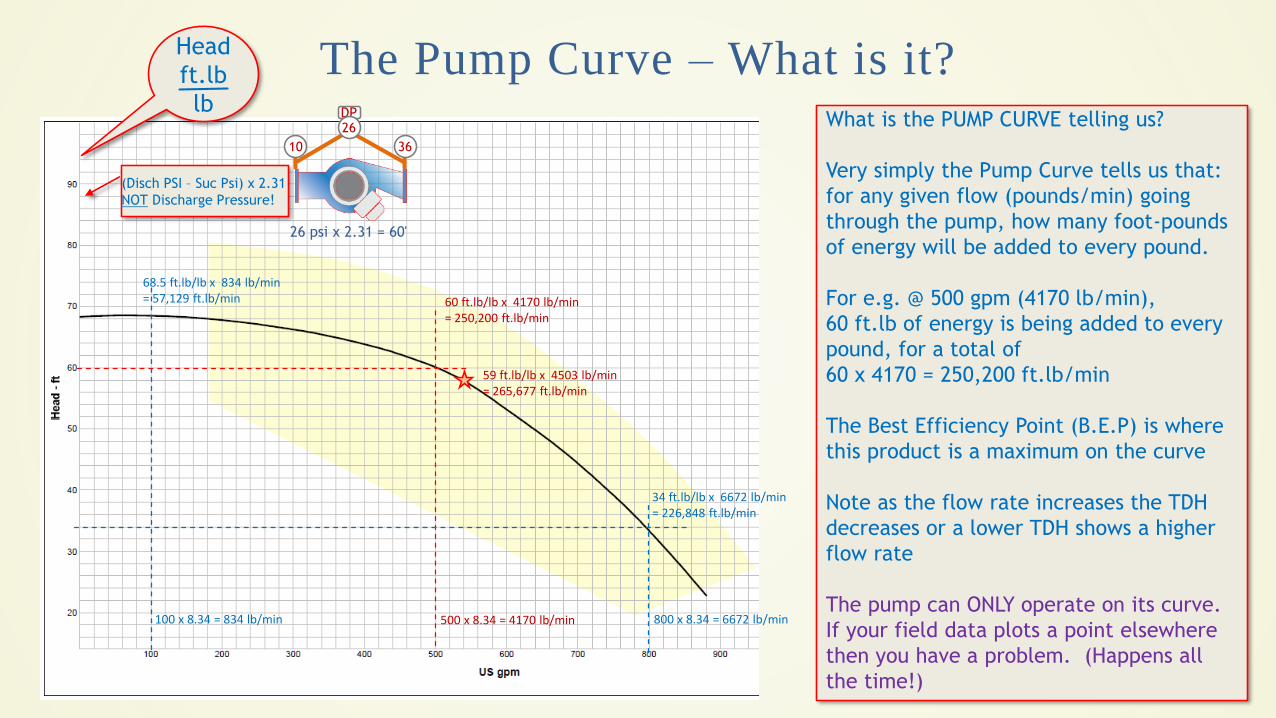
The Pump Curve – What is it?
100 x 8.34 = 834 lb/min 500 x 8.34 = 4170 lb/min 800 x 8.34 = 6672 lb/min
60 ft.lb/lb x 4170 lb/min= 250,200 ft.lb/min
68.5 ft.lb/lb x 834 lb/min= 57,129 ft.lb/min
34 ft.lb/lb x 6672 lb/min= 226,848 ft.lb/min
What is the PUMP CURVE telling us?
Very simply the Pump Curve tells us that:
for any given flow (pounds/min) going
through the pump, how many foot-pounds
of energy will be added to every pound.
For e.g. @ 500 gpm (4170 lb/min),
60 ft.lb of energy is being added to every
pound, for a total of
60 x 4170 = 250,200 ft.lb/min
The Best Efficiency Point (B.E.P) is where
this product is a maximum on the curve
Note as the flow rate increases the TDH
decreases or a lower TDH shows a higher
flow rate
The pump can ONLY operate on its curve.
If your field data plots a point elsewhere
then you have a problem. (Happens all
the time!)
Head
ft.lb
lb
(Disch PSI – Suc Psi) x 2.31
NOT Discharge Pressure!
10 36
DP26
26 psi x 2.31 = 60'
59 ft.lb/lb x 4503 lb/min= 265,677 ft.lb/min
11
Shut-Off DP
for Control
Valves
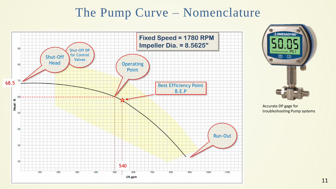
The Pump Curve – Nomenclature
Fixed Speed = 1780 RPM
Impeller Dia. = 8.5625"
Shut-Off
Head
Run-Out
Operating
Point
Best Efficiency Point
B.E.P
540
68.5
Accurate DP gage for troubleshooting Pump systems
12
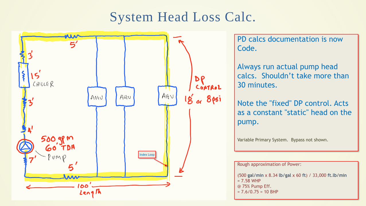
System Head Loss Calc.
PD calcs documentation is now
Code.
Always run actual pump head
calcs. Shouldn’t take more than
30 minutes.
Note the "fixed" DP control. Acts
as a constant "static" head on the
pump.
Variable Primary System. Bypass not shown.
Rough approximation of Power:
(500 gal/min x 8.34 lb/gal x 60 ft) / 33,000 ft.lb/min
= 7.58 WHP
@ 75% Pump Eff.
= 7.6/0.75 = 10 BHP
Index Loop
13
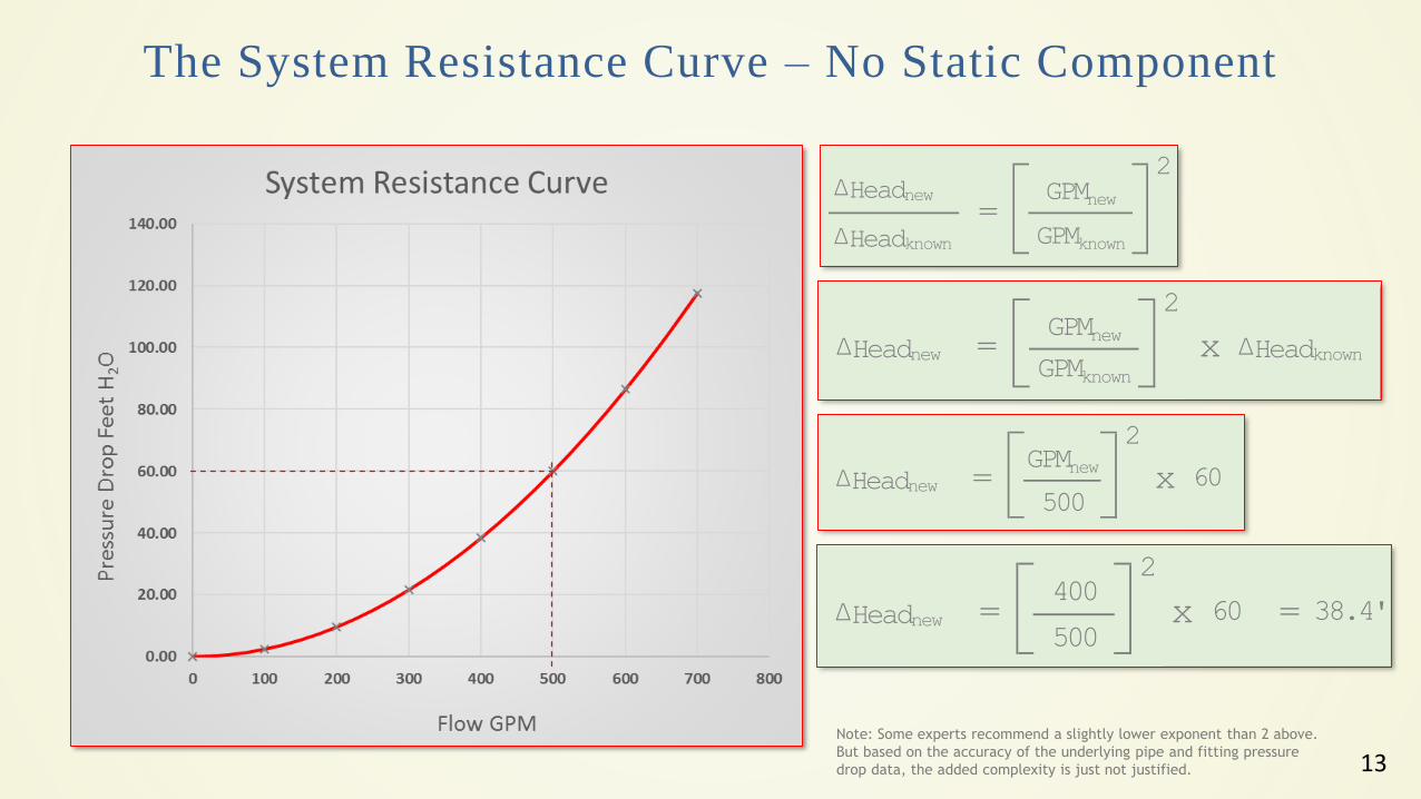
The System Resistance Curve – No Static Component
ΔHeadnew
ΔHeadknown =
GPMnew
GPMknown
2
x ΔHeadknown ΔHeadnew
2GPMnew
=GPMknown
x 60ΔHeadnew
2GPMnew
=500
Note: Some experts recommend a slightly lower exponent than 2 above.
But based on the accuracy of the underlying pipe and fitting pressure
drop data, the added complexity is just not justified.
38.4'x 60 =ΔHeadnew
2400
=500
14
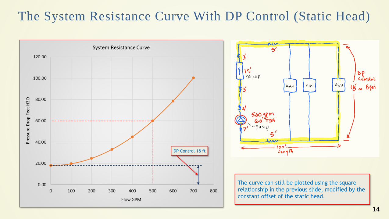
The System Resistance Curve With DP Control (Static Head)
DP Control 18 ft
The curve can still be plotted using the square
relationship in the previous slide, modified by the
constant offset of the static head.
15
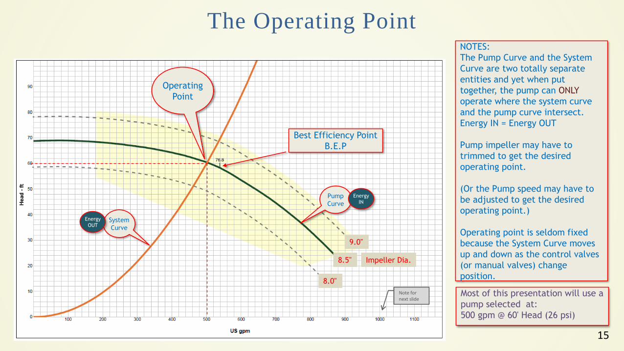
The Operating Point
Operating
Point
Best Efficiency Point
B.E.P
System
Curve
Pump
Curve
9.0"
8.0"
8.5" Impeller Dia.
NOTES:
The Pump Curve and the System
Curve are two totally separate
entities and yet when put
together, the pump can ONLY
operate where the system curve
and the pump curve intersect.
Energy IN = Energy OUT
Pump impeller may have to
trimmed to get the desired
operating point.
(Or the Pump speed may have to
be adjusted to get the desired
operating point.)
Operating point is seldom fixed
because the System Curve moves
up and down as the control valves
(or manual valves) change
position.
Most of this presentation will use a
pump selected at:
500 gpm @ 60' Head (26 psi)
Energy
OUT
Energy
IN
Note for next slide
16
0.0 0.0
DP
0.0Suction Discharge
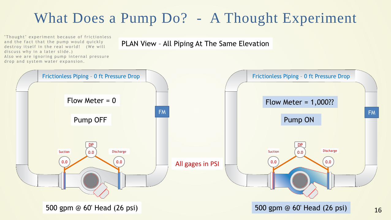
What Does a Pump Do? - A Thought Experiment
PLAN View – All Piping At The Same Elevation
Pump OFF Pump ON
500 gpm @ 60' Head (26 psi) 500 gpm @ 60' Head (26 psi)
Frictionless Piping – 0 ft Pressure Drop Frictionless Piping – 0 ft Pressure Drop
" Though t " expe r iment because o f f r i c t i o n le s s
a nd t he f a c t t ha t t he pump wou ld qu i c k l y
de s t ro y i t s e l f i n t he rea l wo r ld ! (We w i l l
d i s cu s s why i n a l a t e r s l i de . )
A l s o we a re i g no r i ng pump i n te rna l p re s s u re
d rop and s y s t em wa te r expans i on .
0.0 0.0
DP
0.0Suction Discharge
Flow Meter = 0 Flow Meter = 1,000??
All gages in PSI
FM FM
17
43 43
DP
0.0Suction Discharge
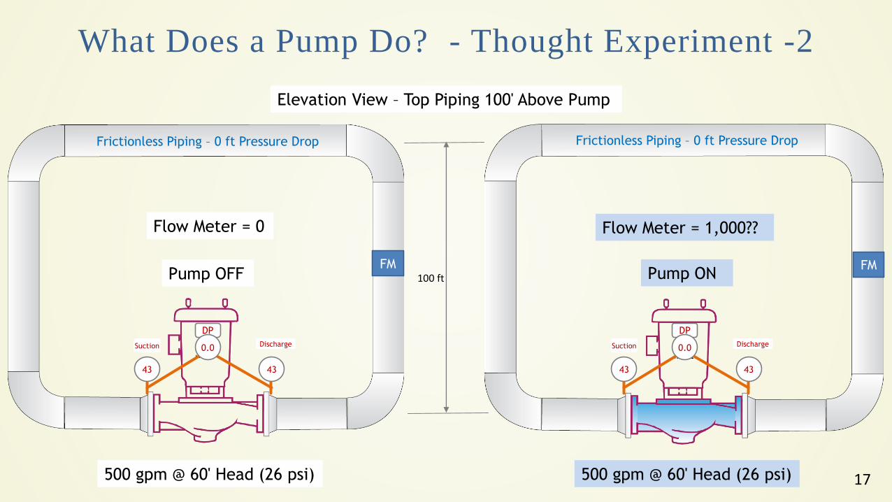
What Does a Pump Do? - Thought Experiment -2
Elevation View – Top Piping 100' Above Pump
Pump OFF Pump ON
500 gpm @ 60' Head (26 psi) 500 gpm @ 60' Head (26 psi)
43 43
DP
0.0Suction Discharge
Flow Meter = 0 Flow Meter = 1,000??
Frictionless Piping – 0 ft Pressure Drop
100 ft
Frictionless Piping – 0 ft Pressure Drop
FM FM
18
43 69
DP
26Suction Discharge
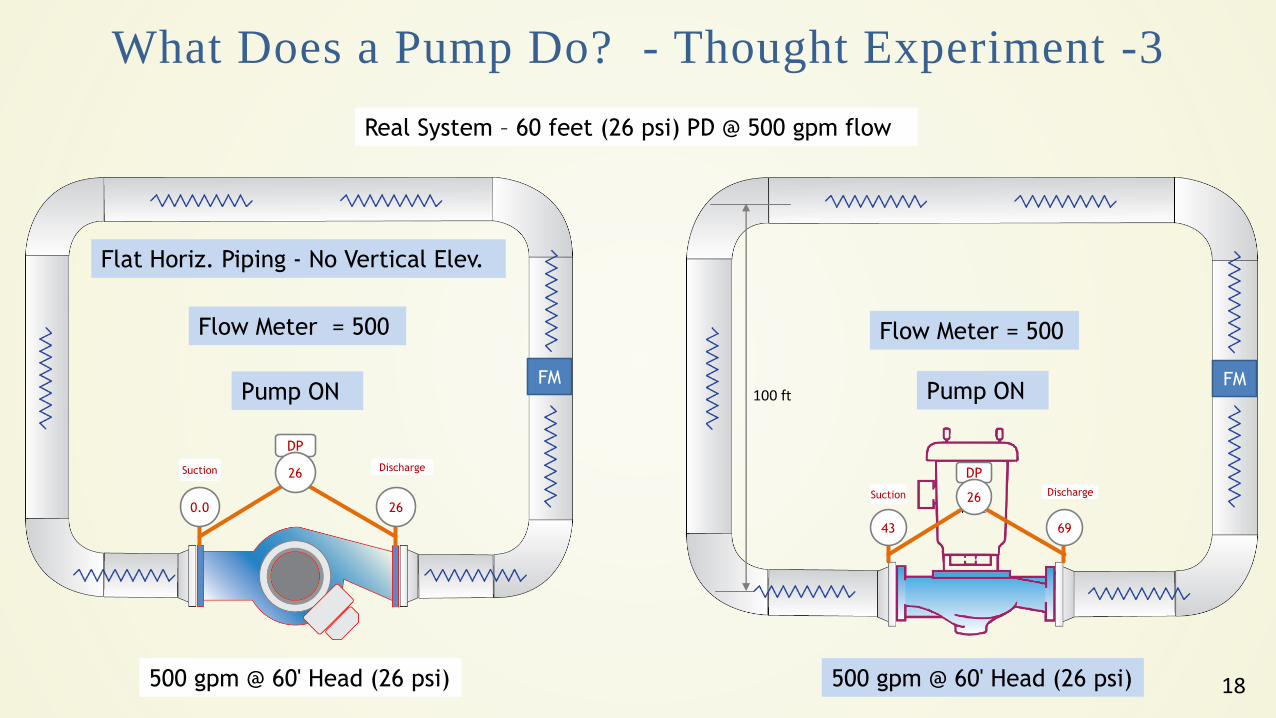
What Does a Pump Do? - Thought Experiment -3
Pump ON
500 gpm @ 60' Head (26 psi) 500 gpm @ 60' Head (26 psi)
Flow Meter = 500 Flow Meter = 500
100 ft
0.0 26
DP
26Suction Discharge
Real System – 60 feet (26 psi) PD @ 500 gpm flow
Pump ONFM FM
Flat Horiz. Piping - No Vertical Elev.
19
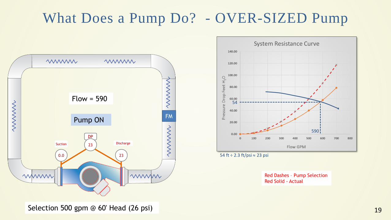
What Does a Pump Do? - OVER-SIZED Pump
Pump ON
Selection 500 gpm @ 60' Head (26 psi)
Flow = 590
0.0 23
DP
23Suction Discharge
54
590
54 ft ÷ 2.3 ft/psi 23 psi
FM
Red Dashes – Pump Selection
Red Solid - Actual
20
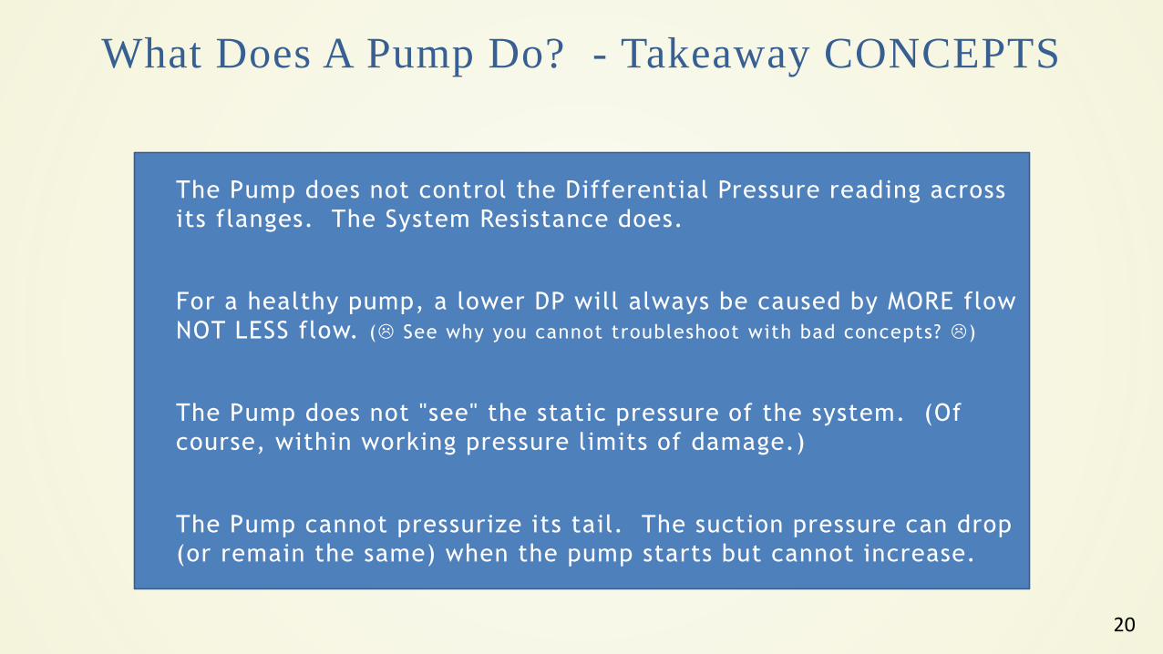
The Pump does not control the Differential Pressure reading across
its flanges. The System Resistance does.
For a healthy pump, a lower DP will always be caused by MORE flow
NOT LESS flow. ( See why you cannot troubleshoot with bad concepts? )
The Pump does not "see" the static pressure of the system. (Of
course, within working pressure limits of damage.)
The Pump cannot pressurize its tail. The suction pressure can drop
(or remain the same) when the pump starts but cannot increase.
What Does A Pump Do? - Takeaway CONCEPTS
21
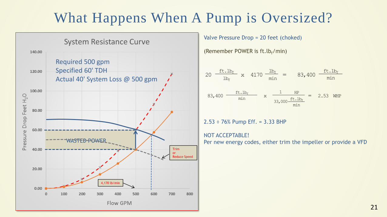
What Happens When A Pump is Oversized?
Required 500 gpm Specified 60' TDHActual 40' System Loss @ 500 gpm
Valve Pressure Drop = 20 feet (choked)
(Remember POWER is ft.lbf/min)
lbf
min
ft.lbf
lbf4170 =
ft.lbf
min83,400 20 x
183,400
ft.lbf
minx 2.53 WHP
ft.lbf
min33,000
HP=
4,170 lb/min
2.53 ÷ 76% Pump Eff. = 3.33 BHP
NOT ACCEPTABLE!
Per new energy codes, either trim the impeller or provide a VFDWASTED POWER
Trim
or
Reduce Speed
22
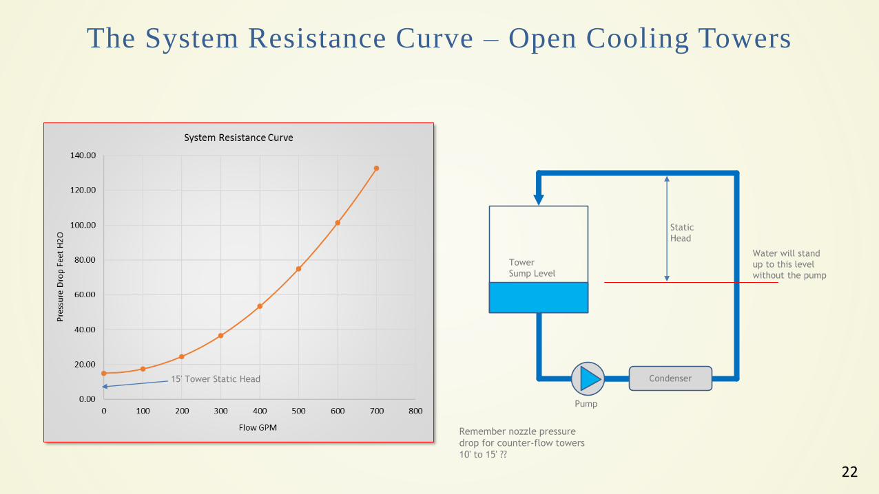
The System Resistance Curve – Open Cooling Towers
Water will stand
up to this level
without the pump
Static
Head
Tower
Sump Level
Pump
Condenser15' Tower Static Head
Remember nozzle pressure
drop for counter-flow towers
10' to 15' ??
23
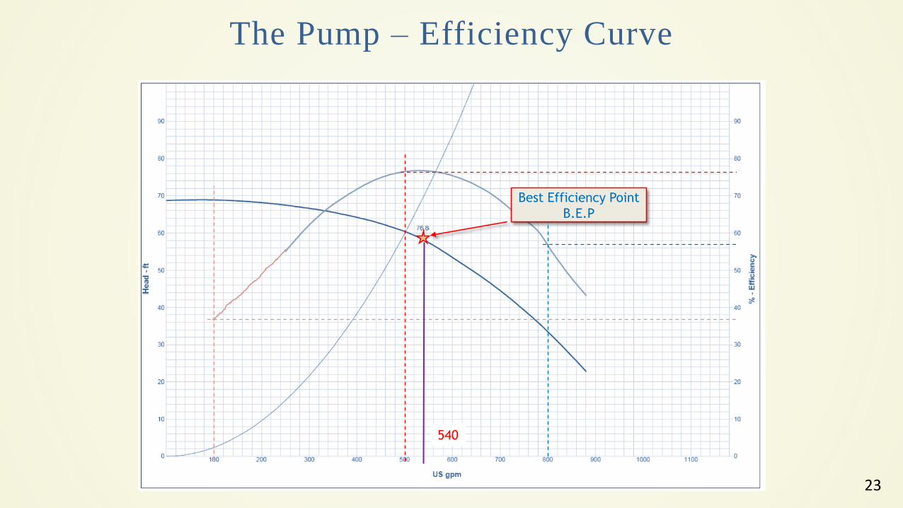
The Pump – Efficiency Curve
540
Best Efficiency Point
B.E.P
24
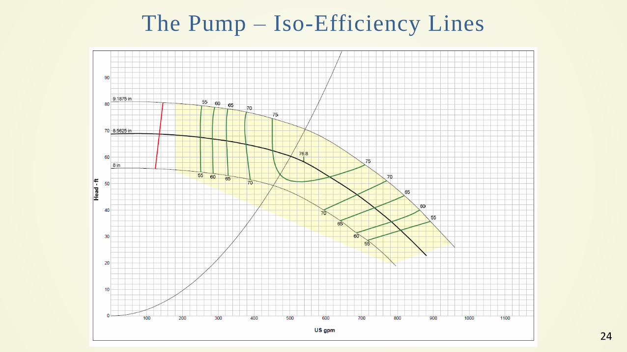
The Pump – Iso-Efficiency Lines
25
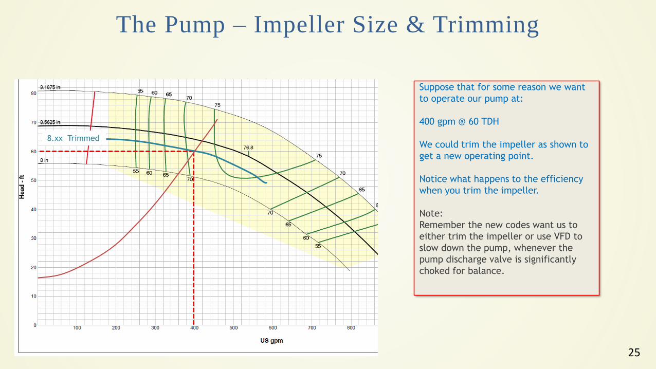
The Pump – Impeller Size & Trimming
8.xx Trimmed
Suppose that for some reason we want
to operate our pump at:
400 gpm @ 60 TDH
We could trim the impeller as shown to
get a new operating point.
Notice what happens to the efficiency
when you trim the impeller.
Note:
Remember the new codes want us to
either trim the impeller or use VFD to
slow down the pump, whenever the
pump discharge valve is significantly
choked for balance.
26
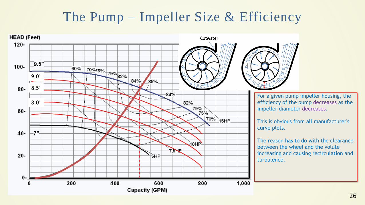
The Pump – Impeller Size & Efficiency
9.0"
8.5"
8.0"
For a given pump impeller housing, the
efficiency of the pump decreases as the
impeller diameter decreases.
This is obvious from all manufacturer's
curve plots.
The reason has to do with the clearance
between the wheel and the volute
increasing and causing recirculation and
turbulence.
27
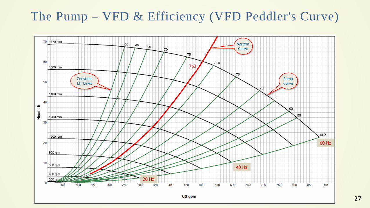
The Pump – VFD & Efficiency (VFD Peddler's Curve)
System
Curve
Constant
Eff Lines
Pump
Curve
20 Hz
60 Hz
40 Hz
76%
28
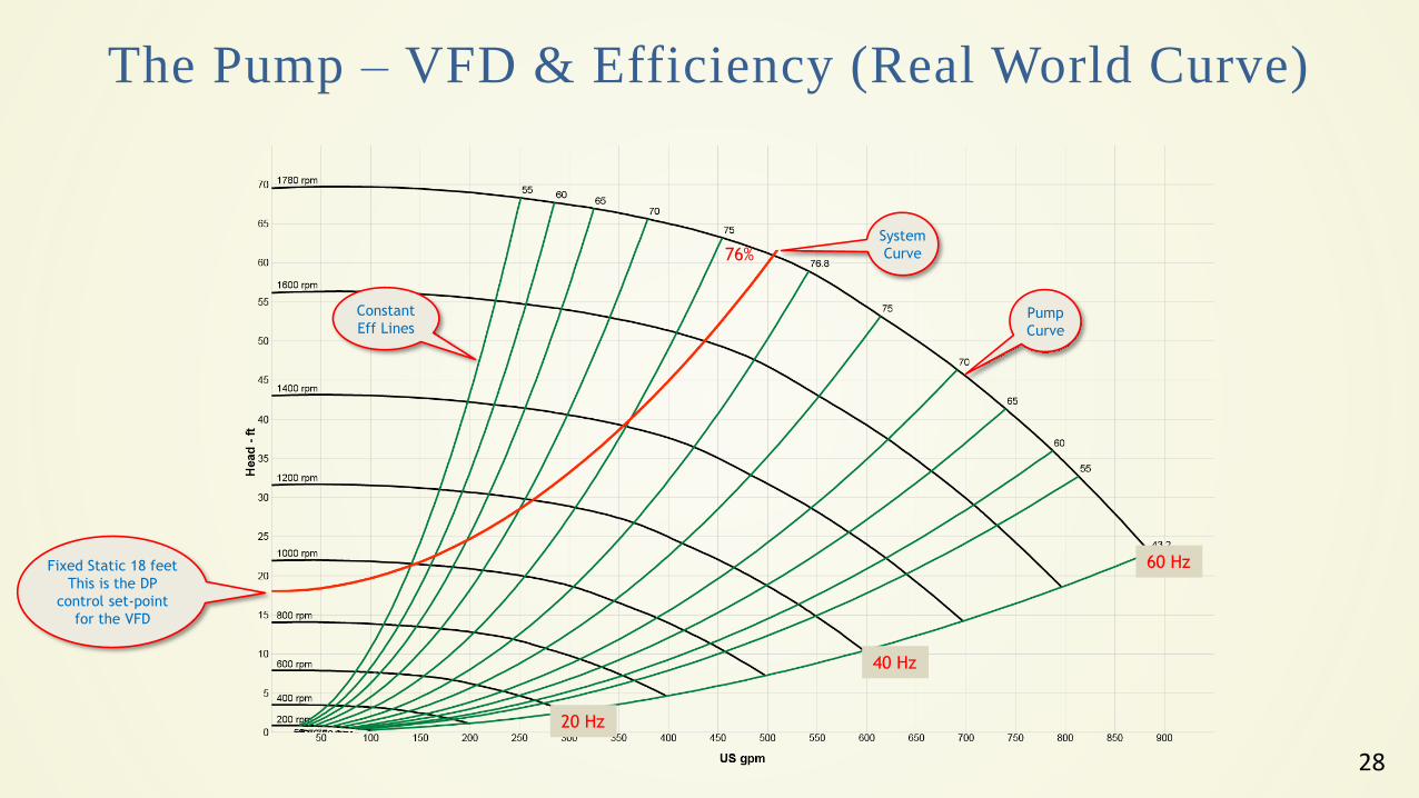
The Pump – VFD & Efficiency (Real World Curve)
System
Curve
Constant
Eff LinesPump
Curve
20 Hz
60 Hz
40 Hz
76%
Fixed Static 18 feet
This is the DP
control set-point
for the VFD
29
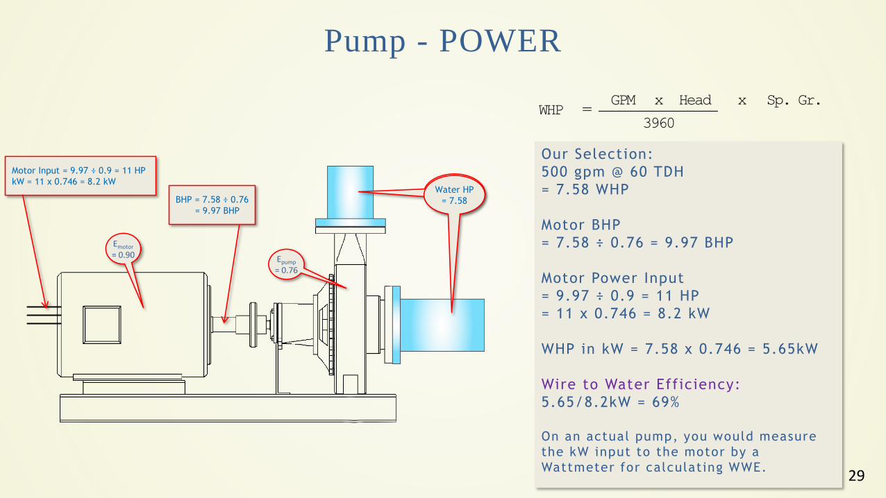
Pump - POWER
Our Selection:
500 gpm @ 60 TDH
= 7.58 WHP
Motor BHP
= 7.58 ÷ 0.76 = 9.97 BHP
Motor Power Input
= 9.97 ÷ 0.9 = 11 HP
= 11 x 0.746 = 8.2 kW
WHP in kW = 7.58 x 0.746 = 5.65kW
Wire to Water Efficiency:
5.65/8.2kW = 69%
On an actual pump, you would measure
the kW input to the motor by a
Wattmeter for calculating WWE.
GPM x Head x Sp. Gr.WHP =
3960
Water HP
= 7.58BHP = 7.58 ÷ 0.76
= 9.97 BHP
Epump
= 0.76
Emotor
= 0.90
Motor Input = 9.97 ÷ 0.9 = 11 HP
kW = 11 x 0.746 = 8.2 kW
30
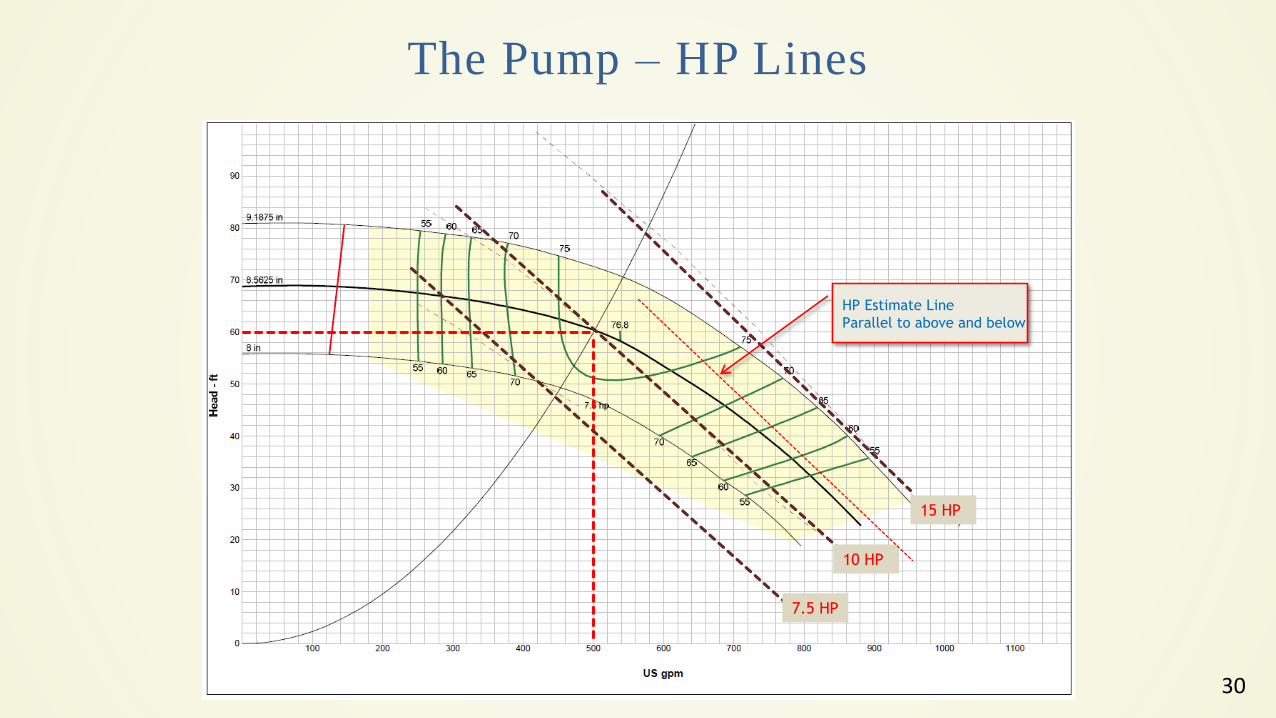
The Pump – HP Lines
15 HP
10 HP
7.5 HP
HP Estimate Line
Parallel to above and below
31
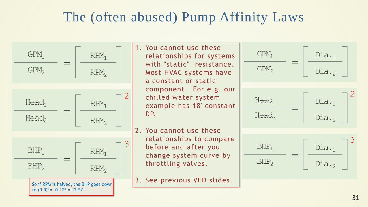
The (often abused) Pump Affinity Laws
GPM1
GPM2
Head1
Head2
BHP1
BHP2
RPM2
RPM2
3
=RPM1
=RPM1
RPM2
2
=RPM1
GPM1
GPM2
Head1
Head2
BHP1
BHP2
3
=Dia.1
Dia.2
=Dia.1
Dia.2
2
=Dia.1
Dia.2
So if RPM is halved, the BHP goes down
to (0.5)3 = 0.125 = 12.5%
1. You cannot use these
relationships for systems
with "static" resistance.
Most HVAC systems have
a constant or static
component. For e.g. our
chilled water system
example has 18' constant
DP.
2. You cannot use these
relationships to compare
before and after you
change system curve by
throttling valves.
3. See previous VFD slides.
32
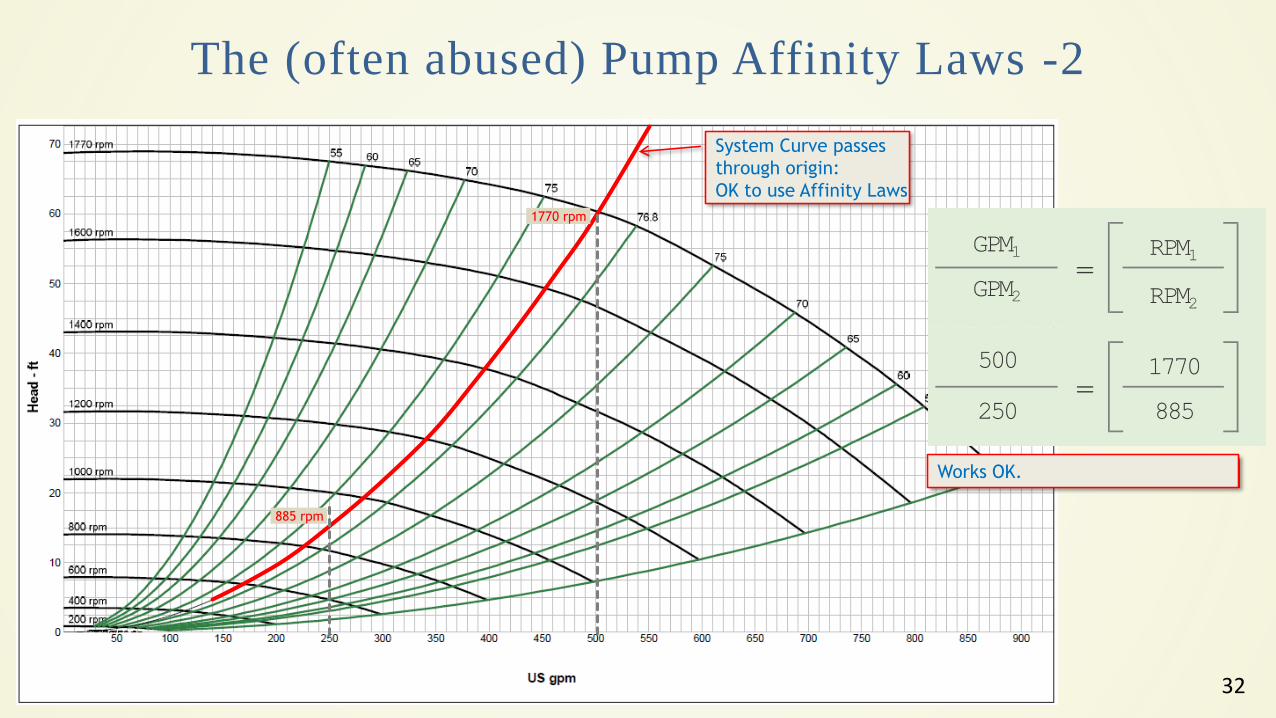
System Curve passes
through origin:
OK to use Affinity Laws
885 rpm
The (often abused) Pump Affinity Laws -2
1770 rpm
GPM1
GPM2=
RPM1
RPM2
500
250=
1770
885
Works OK.
33
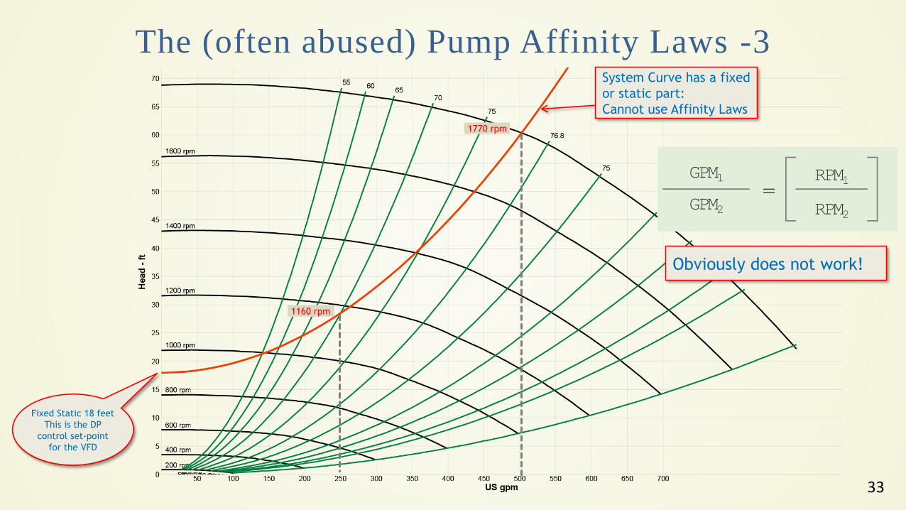
Fixed Static 18 feet
This is the DP
control set-point
for the VFD
The (often abused) Pump Affinity Laws -3System Curve has a fixed
or static part:
Cannot use Affinity Laws
GPM1
GPM2=
RPM1
RPM2
1160 rpm
1770 rpm
Obviously does not work!
34
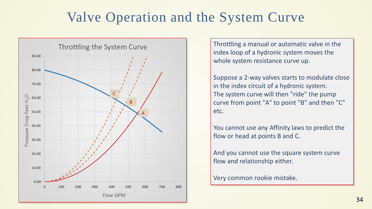
Valve Operation and the System Curve
Throttling a manual or automatic valve in the index loop of a hydronic system moves the whole system resistance curve up.
Suppose a 2-way valves starts to modulate close in the index circuit of a hydronic system.The system curve will then "ride" the pump curve from point "A" to point "B" and then "C" etc.
You cannot use any Affinity laws to predict the flow or head at points B and C.
And you cannot use the square system curve flow and relationship either.
Very common rookie mistake.
A
B
C
35
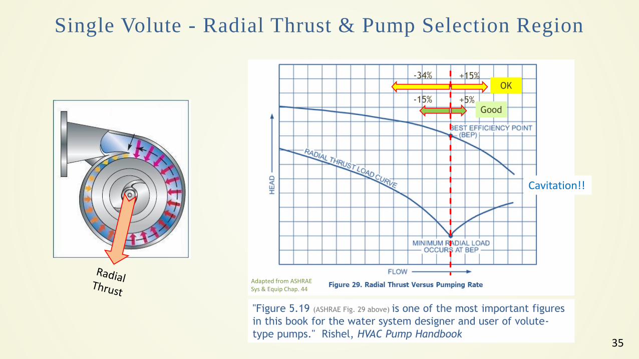
Single Volute - Radial Thrust & Pump Selection Region
"Figure 5.19 (ASHRAE Fig. 29 above) is one of the most important figures
in this book for the water system designer and user of volute-
type pumps." Rishel, HVAC Pump Handbook
+5%-15%
Adapted from ASHRAE Sys & Equip Chap. 44
Cavitation!!
+15%-34%OK
Good
36
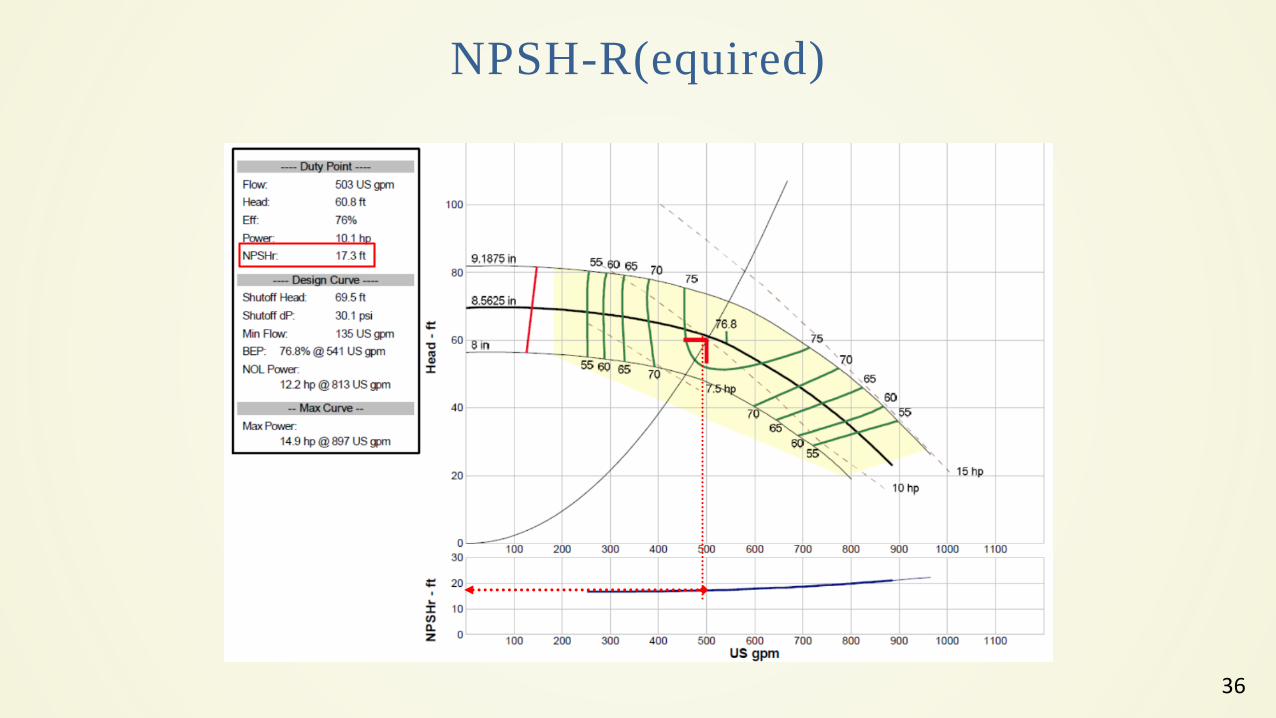
NPSH-R(equired)
37
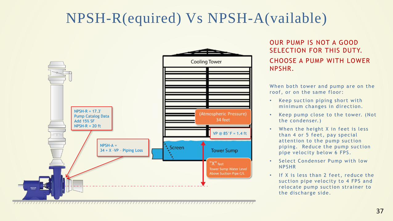
NPSH-R(equired) Vs NPSH-A(vailable)
NPSH-R = 17.3'
Pump Catalog Data
Add 15% SF
NPSH-R = 20 ft
NPSH-A =
34 + X –VP – Piping Loss
VP @ 85°F = 1.4 ft
OUR PUMP IS NOT A GOOD
SELECTION FOR THIS DUTY.
CHOOSE A PUMP WITH LOWER
NPSHR.
When both tower and pump are on the
roof, or on the same f loor:
• Keep suct ion p iping short wi th
min imum changes in d i rect ion.
• Keep pump c lose to the tower. (Not
the condenser.)
• When the he ight X in feet i s less
than 4 or 5 feet , pay spec ia l
at tent ion to the pump suct ion
p iping. Reduce the pump suct ion
p ipe ve loc i ty be low 6 FPS.
• Se lect Condenser Pump with low
NPSHR
• I f X i s less than 2 feet, reduce the
suct ion p ipe ve loc ity to 4 FPS and
re locate pump suct ion st ra iner to
the d i scharge s ide.
38
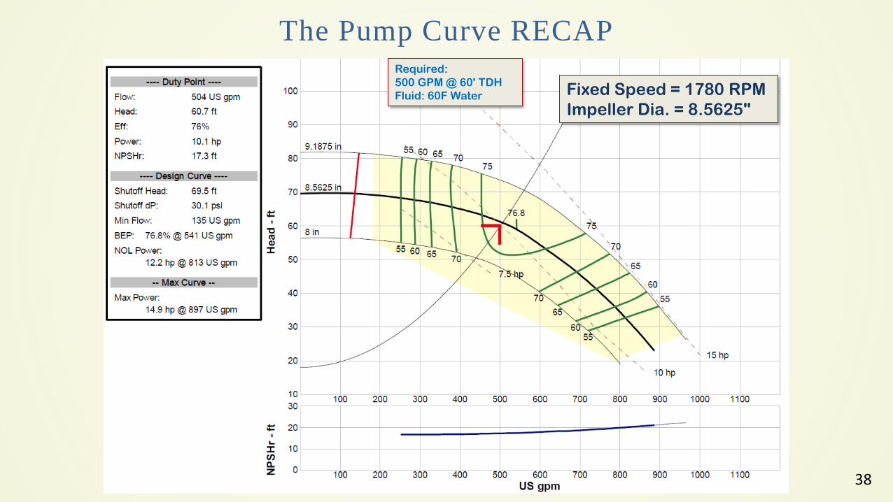
The Pump Curve RECAP
Fixed Speed = 1780 RPM
Impeller Dia. = 8.5625"
Required:
500 GPM @ 60' TDH
Fluid: 60F Water