Embed Size (px)
Citation preview

FACILITIES, EQUIPMENT, AND OTHER RESOURCES IN UNIVERSITY OF SOUTH
CAROLINA
1 LABORATORY FOR ADAPTIVE MATERIALS AND SMART STRUCTURES (LAMSS)
The Department of Mechanical Engineering at the University of South Carolina (USC) has allocated 600
sq. ft. of floor space (a 3-room suite) and important resources for the development of a Laboratory for
Adaptive Materials and Smart Structures (LAMSS). Complete information about this laboratory is
available at the LAMSS website http://www.me.sc.edu/research/lamss/. This laboratory has been
equipped with over $100,000 worth of state of the art specialized equipment for performing active
materials and smart structures research. LAMSS laboratory resources consist of:
1. A complement of standard laboratory equipment including signal generators, amplifiers, digital
oscilloscopes, multimeters, LVDT and optical displacement transducers, etc.
2. Laboratory PC’s equipped with GPIB and DAQ cards and LabView and MATLAB software
3. HP 4194A Impedance Analyzer
4. Cypher Instruments C-60 impedance module, suitable for portable field operations
5. Piezoelectric wafer active sensors (PWAS) of various sizes. Adhesives, connectors, and
environmental protection materials for structural installation
6. Piezoelectric and magnetostrictive actuators of various sizes, and high voltage amplifiers
7. Ultrasonic inspection equipment consisting of a GE Parametrics pulser/receiver and several
ultrasonic transducers in the range 0.5–50 MHz
2 SPECIMENS AND TEST APPARATUS
During the previous research and projects, lots of specimens and test apparatus were designed and used to
assist research and verify theoretical deductions. Some of the critical specimens are:
1. PWAS Lamb-wave propagation experiments: Figure 1 shows a typical setup for performing wave
propagation studies with PWAS-generated Lamb waves. A 1.6 mm thick, 2024-aluminum alloy
plate (914mm x 504mm x 1.6 mm) was instrumented with an array of eleven 7-mm x 7-mm
PWAS. The PWAS were connected with thin insulated wires to a 16-channels signal bus that
ended into two 8-pin connectors. An HP33120A arbitrary signal generator was used to generate a
300 kHz tone-burst excitation with a 10 Hz repetition rate. Both constant-amplitude and
smoothed tone-burst signals were used. The signal was sent a transmitter PWAS and received at
the other 10 receiver PWAS. A Tektronix TDS210 two-channel digital oscilloscope,
synchronized with the signal generator, was used to collect the response signals from the PWAS.
The two oscilloscope channels were digitally switched among the remaining 10 active sensors
using a digitally controlled switching unit. A data acquisition program using LabView software
controlled the switching unit and recorded the data from the digital oscilloscope. A Motorola
MC68HC11 microcontroller was tested as an embedded stand-alone unit.
2. High voltage PWAS Lamb-wave propagation experiments: Figure 2 shows a typical setup for
performing high voltage wave propagation studies with PWAS generated Lamb waves. A Krohn-
Hite wideband Amplifier (Model 7602) can output up to 282Vrms, 34Watt, DC to 1MHz
frequency was used to amplify the excitation signal. This setup is used with thick specimen, or
high attenuation composites specimens.
3. The setup for measuring the electromechanical impedance with the HP4194A Impedance
Analyzer is shown in Figure 3. An aging aircraft panel instrumented with an array of piezoelectric
wafer active sensors (PWAS) is shown connected to the impedance analyzer.
4. Figure 4 shows the experimental setup for the embedded ultrasonic structural radar using PWAS
phased arrays. PWAS array elements were excited in a round robin fashion and the reflections
from structural features were collected by the phased array. Once the interrogation is finished, all

the sensor data from the array are compiled with data processing software developed in LAMSS,
and a reconstructed image of the reflected signal unveils structural anomalies. The software was
named embedded ultrasonic structural radar (EUSR). The EUSR software integrated guided wave
propagation theory, phased array algorithm, data management scheme and visual data
presentation tools, is a convenient yet powerful software for phased array studies conducted in
LAMSS.
5. Figure 5 shows a specimen used to validate the bonded repairs using SHM technology in
collaboration with other specialized companies (e.g., Acellent Technologies, Inc.). The AFRL-
Boeing sponsored project titled “Structural Health Monitoring for Bonded Repairs” took place in
the 2003-2004 timeframe. F-16 wing junction specimens were subjected to low-cycle accelerated
fatigue in AFRL structural tests facilities in order to observe and monitor the behavior of the
bonded composite repair. PWAS phased array and E/M impedance were used during these tests.
Figure 5a shows seven PWAS installed on the wing junction bonded repair specimen. The E/M
impedance spectra measured during the fatigue cycling at various cycle counts are shown Figure
5b. It is apparent that the E/M spectrum showed dramatic changes (frequency shifts and
significant increase of resonance peaks) prior to the final disbonding of the composite patch
repair. In fact, the PWAS indications were observed earlier than other indications taken with a
conventional ultrasonic bond tester. Another set of PWAS used on this specimen consisted of
phased arrays, which were processed with the embedded ultrasonic structural radar (EUSR)
algorithm.
6. Figure 6 shows AFRL—Triad Semiconductors project with the title “Development of a Multi-
Sensor Structural Health Monitoring System Using Embedded Piezoelectric Sensors” took place
in the 2003-2005 timeframe and consisted of collaboration between two universities (University
of South Carolina and North Carolina A&T State University) and a company (Triad
Semiconductors, Inc.) under AFRL NDE branch sponsorship. The project objective was to
develop an SHM system that would combine the active sensing technology developed by USC
with the acoustic emission passive sensing technology developed by NC A&T into a working
system to be tested at AFRL. The project started with initial sensor developments done
independently at each university using coupon specimens and culminated with a common test
done on a real aircraft structure specimen at UDRI testing facility in Dayton, OH (Figure 6a). In
the project, each university developed the sensors and the specific methodology, whereas Triad
Semiconductors developed the electronic hardware that would integrate the two sensing methods.
7. Figure 7 shows a specimen used during the development of shear lag solution for the stress/strain
transfer between a structurally attached PWAS and the support structure. Earlier studies of this
subject 8 assumed axial and flexural vibrations with linear strain distribution across the thickness;
this assumption is fine for low values of the frequency-thickness product fd , but would not be
appropriate for ultrasonic guided waves (e.g., Lamb waves) because the latter have complicated
multi-mode strain distributions across the thickness. To overcome this limitation, Giurgiutiu and
Santoni-Bottai [2] derived a generic shear lag solution that is not limited to the low frequency-
thickness values. This generic solution takes into account the exact thickness distribution of
displacements and stresses corresponding to the Lamb wave modes existing at a particular
ultrasonic frequency-thickness product value. This study [2] showed that essential parameters
such as the axial-flexural repartition number, , and the shear lag parameter, as well as the
tuning curves depend on the frequency-thickness product.
8. Figure 8 shows a test used to detect damage due to cyclic loading. Composite coupons were
instrumented with PWAS and conventional foil strain gauges. The strain gauge data was used as a
reference to record the loading history. Baseline data was collected on pristine specimens. The
specimens were into extension loading group and compression loading group to evaluate the
sensitivity of PWAS to different fatigue damage types. With pitch-catch, pulse echo, and E/M
impedance methods, data were collected.
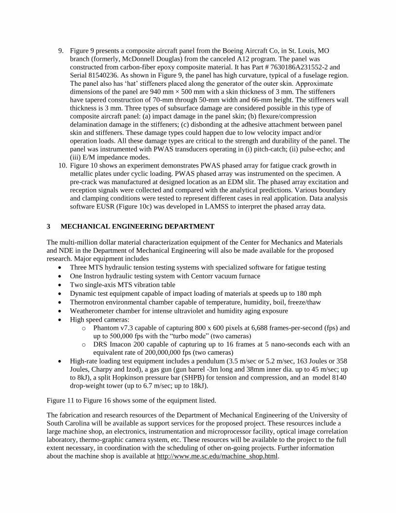
9. Figure 9 presents a composite aircraft panel from the Boeing Aircraft Co, in St. Louis, MO
branch (formerly, McDonnell Douglas) from the canceled A12 program. The panel was
constructed from carbon-fiber epoxy composite material. It has Part # 7630186A231552-2 and
Serial 81540236. As shown in Figure 9, the panel has high curvature, typical of a fuselage region.
The panel also has ‘hat’ stiffeners placed along the generator of the outer skin. Approximate
dimensions of the panel are 940 mm × 500 mm with a skin thickness of 3 mm. The stiffeners
have tapered construction of 70-mm through 50-mm width and 66-mm height. The stiffeners wall
thickness is 3 mm. Three types of subsurface damage are considered possible in this type of
composite aircraft panel: (a) impact damage in the panel skin; (b) flexure/compression
delamination damage in the stiffeners; (c) disbonding at the adhesive attachment between panel
skin and stiffeners. These damage types could happen due to low velocity impact and/or
operation loads. All these damage types are critical to the strength and durability of the panel. The
panel was instrumented with PWAS transducers operating in (i) pitch-catch; (ii) pulse-echo; and
(iii) E/M impedance modes.
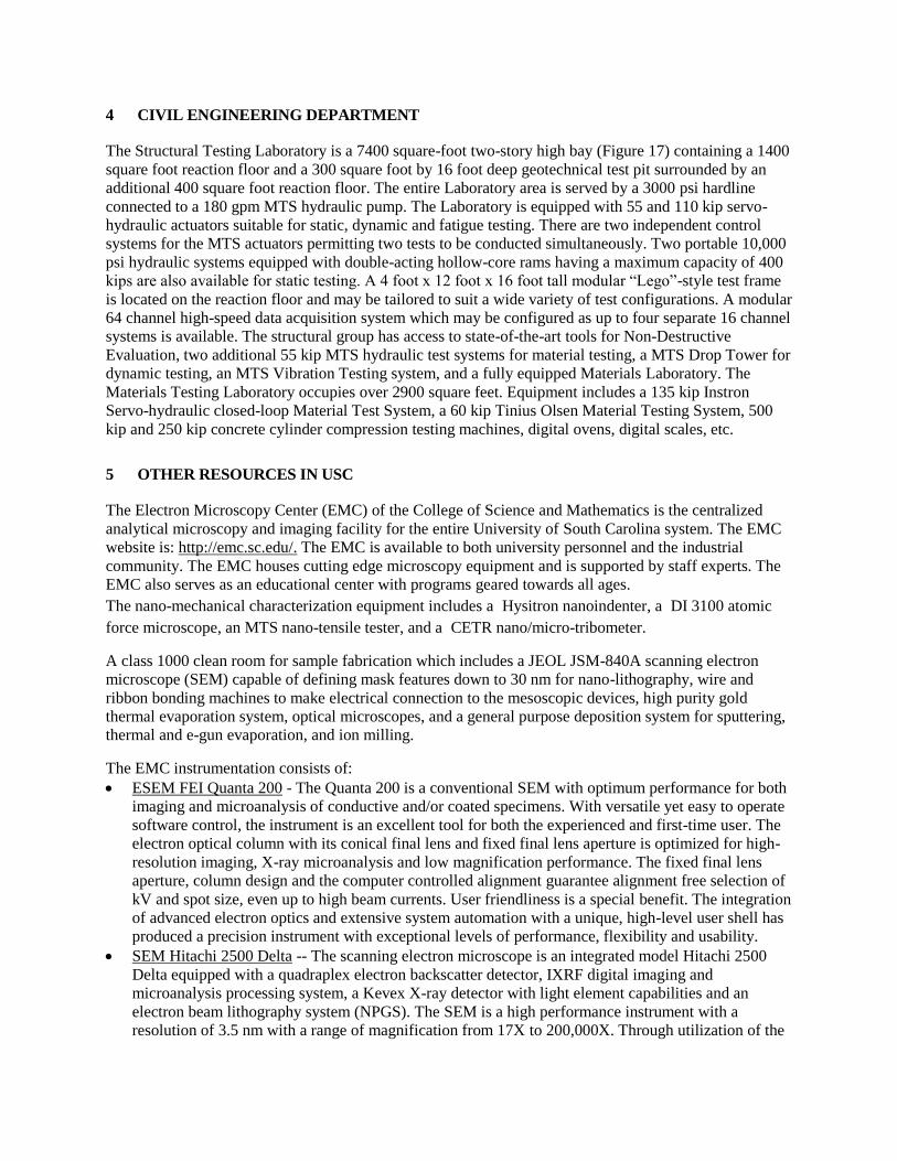
10. Figure 10 shows an experiment demonstrates PWAS phased array for fatigue crack growth in
metallic plates under cyclic loading. PWAS phased array was instrumented on the specimen. A
pre-crack was manufactured at designed location as an EDM slit. The phased array excitation and
reception signals were collected and compared with the analytical predictions. Various boundary
and clamping conditions were tested to represent different cases in real application. Data analysis
software EUSR (Figure 10c) was developed in LAMSS to interpret the phased array data.
3 MECHANICAL ENGINEERING DEPARTMENT
The multi-million dollar material characterization equipment of the Center for Mechanics and Materials
and NDE in the Department of Mechanical Engineering will also be made available for the proposed
research. Major equipment includes
Three MTS hydraulic tension testing systems with specialized software for fatigue testing
One Instron hydraulic testing system with Centorr vacuum furnace
Two single-axis MTS vibration table
Dynamic test equipment capable of impact loading of materials at speeds up to 180 mph
Thermotron environmental chamber capable of temperature, humidity, boil, freeze/thaw
Weatherometer chamber for intense ultraviolet and humidity aging exposure
High speed cameras:
o Phantom v7.3 capable of capturing 800 x 600 pixels at 6,688 frames-per-second (fps) and
up to 500,000 fps with the “turbo mode” (two cameras)
o DRS Imacon 200 capable of capturing up to 16 frames at 5 nano-seconds each with an
equivalent rate of 200,000,000 fps (two cameras)
High-rate loading test equipment includes a pendulum (3.5 m/sec or 5.2 m/sec, 163 Joules or 358
Joules, Charpy and Izod), a gas gun (gun barrel -3m long and 38mm inner dia. up to 45 m/sec; up
to 8kJ), a split Hopkinson pressure bar (SHPB) for tension and compression, and an model 8140
drop-weight tower (up to 6.7 m/sec; up to 18kJ).
Figure 11 to Figure 16 shows some of the equipment listed.
The fabrication and research resources of the Department of Mechanical Engineering of the University of
South Carolina will be available as support services for the proposed project. These resources include a
large machine shop, an electronics, instrumentation and microprocessor facility, optical image correlation
laboratory, thermo-graphic camera system, etc. These resources will be available to the project to the full
extent necessary, in coordination with the scheduling of other on-going projects. Further information
about the machine shop is available at http://www.me.sc.edu/machine_shop.html.
4 CIVIL ENGINEERING DEPARTMENT
The Structural Testing Laboratory is a 7400 square-foot two-story high bay (Figure 17) containing a 1400
square foot reaction floor and a 300 square foot by 16 foot deep geotechnical test pit surrounded by an
additional 400 square foot reaction floor. The entire Laboratory area is served by a 3000 psi hardline
connected to a 180 gpm MTS hydraulic pump. The Laboratory is equipped with 55 and 110 kip servo-
hydraulic actuators suitable for static, dynamic and fatigue testing. There are two independent control
systems for the MTS actuators permitting two tests to be conducted simultaneously. Two portable 10,000
psi hydraulic systems equipped with double-acting hollow-core rams having a maximum capacity of 400
kips are also available for static testing. A 4 foot x 12 foot x 16 foot tall modular “Lego”-style test frame
is located on the reaction floor and may be tailored to suit a wide variety of test configurations. A modular
64 channel high-speed data acquisition system which may be configured as up to four separate 16 channel
systems is available. The structural group has access to state-of-the-art tools for Non-Destructive
Evaluation, two additional 55 kip MTS hydraulic test systems for material testing, a MTS Drop Tower for
dynamic testing, an MTS Vibration Testing system, and a fully equipped Materials Laboratory. The
Materials Testing Laboratory occupies over 2900 square feet. Equipment includes a 135 kip Instron
Servo-hydraulic closed-loop Material Test System, a 60 kip Tinius Olsen Material Testing System, 500
kip and 250 kip concrete cylinder compression testing machines, digital ovens, digital scales, etc.
5 OTHER RESOURCES IN USC
The Electron Microscopy Center (EMC) of the College of Science and Mathematics is the centralized
analytical microscopy and imaging facility for the entire University of South Carolina system. The EMC
website is: http://emc.sc.edu/. The EMC is available to both university personnel and the industrial
community. The EMC houses cutting edge microscopy equipment and is supported by staff experts. The
EMC also serves as an educational center with programs geared towards all ages.
The nano-mechanical characterization equipment includes a Hysitron nanoindenter, a DI 3100 atomic
force microscope, an MTS nano-tensile tester, and a CETR nano/micro-tribometer.
A class 1000 clean room for sample fabrication which includes a JEOL JSM-840A scanning electron
microscope (SEM) capable of defining mask features down to 30 nm for nano-lithography, wire and
ribbon bonding machines to make electrical connection to the mesoscopic devices, high purity gold
thermal evaporation system, optical microscopes, and a general purpose deposition system for sputtering,
thermal and e-gun evaporation, and ion milling.
The EMC instrumentation consists of:
ESEM FEI Quanta 200 - The Quanta 200 is a conventional SEM with optimum performance for both
imaging and microanalysis of conductive and/or coated specimens. With versatile yet easy to operate
software control, the instrument is an excellent tool for both the experienced and first-time user. The
electron optical column with its conical final lens and fixed final lens aperture is optimized for high-
resolution imaging, X-ray microanalysis and low magnification performance. The fixed final lens
aperture, column design and the computer controlled alignment guarantee alignment free selection of
kV and spot size, even up to high beam currents. User friendliness is a special benefit. The integration
of advanced electron optics and extensive system automation with a unique, high-level user shell has
produced a precision instrument with exceptional levels of performance, flexibility and usability.
SEM Hitachi 2500 Delta -- The scanning electron microscope is an integrated model Hitachi 2500
Delta equipped with a quadraplex electron backscatter detector, IXRF digital imaging and
microanalysis processing system, a Kevex X-ray detector with light element capabilities and an
electron beam lithography system (NPGS). The SEM is a high performance instrument with a
resolution of 3.5 nm with a range of magnification from 17X to 200,000X. Through utilization of the

Digital acquisition software provided by IXRF, images can be taken, processed, and printed on to our
photographic quality dye sublimation printer. TEM Hitachi H-8000 - The Hitachi H-8000 is a
transmission electron microscope capable of accelerating voltages from 75-200kv. It can provide a
magnification from three thousand to one million with resolution of 0.14 nm. The Hitachi is primarily
used for materials research and is an analytical microscope that is equipped with a side entry
goniometer, STEM, X-ray microanalysis that is integrated with an IXRF system, and digital AMT
CCD Camera. TEM Jeol 100 CX II - The Jeol 100 CX II is a transmission electron microscope
capable of accelerating voltages from 20-100kv. It can provide magnification from 100x to 600000x
and a resolution of 0.2nm. The instrument is user friendly and rarely needs alignment. The Jeol is
primarily used in analysis of biological specimens. The Jeol is equipped with a side entry goniometer
and in the future a CCD camera and digital interface will be incorporated into the hardware of the
microscope.
EMPA Cameca SX50 - The electron microprobe analysis facility is a non-destructive method ideal
for materials characterization, such as quantitative chemical analysis, X-ray mapping, and imaging.
This technique is used to obtain chemical data and images that show the distribution and variation of
a material's constituents. The technique combines high sensitivity (~0.01 wt % detection limit), high
speed (seconds to minutes per analysis), high precision and accuracy (1-2 % errors), and high spatial
resolution (0.001mm analysis area). Integrated optical microscope imaging allows visual selection of
specific sample features to measure. Solid materials such as alloys, semiconductors, ceramics,
borosilicate glasses, rocks, or minerals can be analyzed for major, minor, and trace elements.
Confocal Microscope Bio-Rad MRC 1024 - The multi-photon laser scanning confocal microscope
system is probably the most important development in fluorescence microscopy since the introduction
of confocal imaging in the mid-1980’s. It provides researchers with unique possibilities when
imaging deep into live tissues and carrying out experiments over extended periods of time. Bio-Rad
pioneered the commercial application of multi-photon techniques. The first commercial multi-photon
system was delivered in 1996.
6 COMPUTER
Computer facilities with standard software programs are widely available at various locations in all the
departments participating in this proposal. Each participating department has a large number of PC’s
equipped with state of the art software for research applications placed in the laboratories, graduate
student offices, and faculty offices. In addition, we have dedicated computer labs with banks of PC’s that
are on upgraded periodically under a lease contract with the PC manufacturer. A computer
communication local area network (LAN) with wireless capabilities is installed in all the buildings.
Faculty and students have instant access to the network from class rooms, laboratories, and offices. This
allows them to fully utilize the modern computer facilities available throughout the universities. For
intensive computation, online accesses to the extensive computational facilities of several National Labs
exist.
7 OFFICE
The key investigators are provided with faculty offices, while the graduate students are provided with
office space in dedicated room suits and in the labs. These resources include secretarial and photocopying
support, courier services, etc. Also available are extensive library facilities.
8 REFERENCES
[1] Crawley, E. F.; De Luis, J. (1987) “Use of Piezoelectric Actuators as Elements of Intelligent

Structures”, AIAA Journal, Vol. 25, No. 10, pp. 1373-1385, 1987
[2] Giurgiutiu, V.; Bottai-Santoni, G. (2009) “An Extension of the Shear Lag Solution for Structurally
Attached Ultrasonic Active Sensors”, AIAA Journal, vol. 47, issue 8, pp. 1980-1983, Technical
Notes, August 2009
9 MAJOR EQUIPMENT PICTURES
Figure 1 Experimental setup for PWAS Lamb-wave propagation experiments in LAMSS: (a)
photograph of the overall setup (b) detail of the microcontroller switching unit
Figure 2 Experimental setup for high voltage PWAS Lamb-wave propagation experiments in LAMSS
HP33120A Signal generator
1.6 mm thick aluminum plate with 11 PWAS
Digitally controlled signal switch
NI data acquisition
TDS210 Digital oscilloscope
TDS210 Digital oscilloscope
Switching unit
8-channel signal input/output
Signal/Source connector
Digital display
MC68HC11 Microcontroller
(a) (b)
HP 33120A
Signal generator
Krohn-Hite wideband
Amplifier Tektronix digital
phosphor oscilloscope
Data acquisition
Aluminum plate
specimen

Figure 3 Typical experimental setup using the HP4194A Impedance Analyzer to measure the electromechanical (E/M) impedance in LAMSS
Figure 4 Experimental setup for the embedded ultrasonic structural radar using PWAS phased arrays: (a) experimental setup (b) reconstructed array data image
Figure 5 Testing of F-16 wing junction bonded composite patch repair in AFRL lab: (a) seven PWAS
9-element PWAS array
Data acquisition
PC
TDS-210 digital
oscilloscope
Aluminum plate
specimen
HP-33120A signal
generator
(a) (b)
12.5-mm EDM crack
Piezoelectric active sensors
#1 #2 #3 #4 Rivet head
Aging Aircraft Panel
HP4194A Impedance Analyzer
PWAS 03 with 2nd Baseline
50
100
150
200
250
300
200 300 400 500 600 700 800 900 1000
Frequency (kHz)
Imp
ed
an
ce
2nd Baseline
500 cyc
1000 cyc
1500 cyc
2000 cyc
2500 cyc
3000 cyc
4000 cyc
4695 cyc
Baseline
5000 cycles

transducers installed on composite patch; (b) E/M impedance spectrum on PWAS 03 shows increasing resonance peak and frequency shift as disbond progresses with LC fatigue cycling
(a) (b)
Figure 6 Multi-sensor structural health monitoring testing of actual aircraft component at UDRI lab: (a) Al Wicks (Triad Inc.), Victor Giurgiutiu (U of SC), Lt. Freemantle (AFRL), Mannur Sundaresan (NC A&T); (b) detail of sensors installation
Figure 7 Bond-layer interaction between PWAS and structure: (a) micrograph; (b) modeling
PWAS, 0.2-mm thick
Substrate structure, 1-mm thick
Bond layer
(a)
PWAS
-a +a
x
(x)eitta
t
tb
(b)

Figure 8 Cyclic loading test on composite coupon specimens
Figure 9: Integrated composite panel from the canceled A-12 program was used for predictive simulation of impact-damage detection

Figure 10 PWAS phased array instrumented on fatigue specimen was used to monitor fatigue crack growth. (a) schematic of fatigue specimen; (b) specimen under cyclic loading, clay was used to damp reflection from clamps; (c) phased array data analysis software EUSR showing crack detected
Figure 11 MTS tensile test machines (a) MTS 810 capable of static and cyclic loadings up to 500kN (b) Instron 8501 capable of up to 10 Hz cyclic loading for fatigue testing (c) MTS equipped with ATS3710 oven can perform tensile test at temperature between -300F and 800F
(a) (b) (c)
(a) (b) (c)

Figure 12 MTS vibration test machine and drive up to 200Hz in University of South Carolina
Figure 13 shock test systems (a) MTS drop tower 8ft drop tower (up to 600 lbs specimen) (b) Instron 8140 drop-weight tower (up to 6.7 m/sec; up to 18kJ).
(a) (b)

Figure 14 Environmental testing equipments in University of South Carolina (a) Thermotron SE-300; (b) Atlas Weather-ometer; and (c) Humboldt EC3400 rapid freeze-thaw cabinet
Figure 15 Blue M 6680 Ultra-temp industrial oven in University of South Carolina
(a) (b) (c)

Figure 16 High-speed cameras in the Department of Mechanical Engineering at University of South Carolina: (a) Phantom v7.3; (b) DRS Imacon 200
Figure 17 Civil engineering department Structural Testing Laboratory has a 7400 square-foot two-story high bay containing various testing equipment
(a) (b)

Figure 18 Class-1000 clean room in USC nanocenter: (a) Scanning electron microscope (b) Fume hoods (c) From left to right, heated ribbon bonder, wire bonder, and high purity gold thermal evaporator.
(a) (b)
(c)

Figure 19 USC Electron Microscopy Center (EMC) instrumentation (a) FEI Quanta 200 ESEM (b)
Cameca SX50 EMPA (c) Hitachi H-8000 TEM (d)JEOL JEM 2100F
(a) (b)
(c) (d)