Embed Size (px)
Citation preview

PQE203 - A
© 2007 by PowerCET Corporation, All rights reserved1
Facility and Equipment Grounding - 2005Course: PQE203
Presented by:
PowerCET Corporation3350 Scott Blvd. Bldg. 55 Unit 1Santa Clara, CA 95054408/988-1346 | Fax 408/988-4869E-mail: [email protected]: http://www.powercet.com
Grounding
Earthing–Establishing a bond to earth at the facility service entrance for the electrical distribution system
Grounding (U.S. Convention)–Establishing fault clearing paths within a facility for the electrical distribution system and for equipment within the facility.
Referencing–Establishing a chassis contact to an external point to limit voltage rise.
MagicGrounding Grounding
ScienceVs

PQE203 - A
© 2007 by PowerCET Corporation, All rights reserved2
Origins For Grounding Concepts
Electrical code–Single point grounding–Fault path to electrical service
Telecommunications grounding–Traditional DC grounding practices–Ground start & signaling
RF grounding–Antenna grounding
Isolated grounding–U.S. practice
"Earthing" Systems
Three or four letter designationFirst letter is supply earthing–T indicates one or more points directly earthed–I indicates the supply is not earthed or is earthed through a fault limiting impedance
Second letter indicates installation earthing–T indicates that conductive metalwork is directly connected to earth
–N indicates that conductive metalwork is directly connected to the earthed neutral.
US convention is TN -- not TT or IT

PQE203 - A
© 2007 by PowerCET Corporation, All rights reserved3
Earthing Systems 2
Third and fourth letter describes earthed conductor arrangement–S indicates separate neutral and earthed conductors–C indicates combined neutral and earth conductor
TN-S: consumers earth terminal connected to the supply protective conductorTN-C: consumers neutral and protective functions (ground) in a single conductorTN-C-S: consumers supply neutral and protective functions (ground) are combined and earthed at several points (US Convention)
IT Earthing SystemUtility not earthed or earthed via impedanceFacility earthed independently of utility

PQE203 - A
© 2007 by PowerCET Corporation, All rights reserved4
TT Earthing SystemUtility directly earthed Facility earthed independently of utility
TN Earthing SystemUtility directly earthed (and frequently in US)Facility grounding bonded to earthed utility

PQE203 - A
© 2007 by PowerCET Corporation, All rights reserved5
Grounding ConceptsThe effects of impedance & frequencyFaraday cage & Kirchoff's Voltage and Current LawsNational Electrical Code–76 different references in the 2002 code–Extensive changes to Articles 250 and 800–Many exemptions for grounding of cord and plug connected equipment in NEC 250.114 [2002 - 2005]
Essential Grounding References

PQE203 - A
© 2007 by PowerCET Corporation, All rights reserved6
Earthing/Grounding Means
Grounding Electrode System
The Roles of Grounding
General requirements–NEC 250.4 [2002 & 2005]–Establish voltage reference–Limit touch potential–Clear electrical faults–Carry lightning currents
Performance issues–Provide equipment reference–Provide RF/ESD discharge path

PQE203 - A
© 2007 by PowerCET Corporation, All rights reserved7
National Electrical Code Article 250–Electrical service entrance bonding
NEC 250-5 [1996] & NEC 250-20 [1999 - 2005]Incoming utility neutral or internal facility neutral
–Grounding electrode system - NEC 250.50Structural steel where effectively grounded"All grounding electrodes as described in 250.51(A)(1) through (A)(6) that are present at each building or structure served shall be bonded together to form the grounding electrode system."Ufer grounds (concrete encased electrode)Building footings if designed as Ufer groundsWater pipesGround ringPlate electrodesDriven grounding rods
Grounding Electrode System (GES)
GroundRod
WaterPipe
StructuralSteel
WaterPipe
StructuralSteel
–Underground water pipe cannot be the sole grounding meansNEC 250-(a)(2) [1999] & NEC 250.53(D)(2) [2002-2005]Must be supplemented by a made electrodeBond within 5' of point of entry
Bonds to Water Pipes

PQE203 - A
© 2007 by PowerCET Corporation, All rights reserved8
Grounding Electrode System 2
GES - NEC 250-50 [2005]–Water Pipe - NEC 250.52(A)(1)–Driven Ground - NEC 250.52(A)(5)–Structural Steel - NEC 250.52(A)(2)
Grounding electrode conductor must be continuous
–NEC 250.64(C) [2002 & 2005]
Not allowed–Metal underground gas pipes–Aluminum electrodes–NEC 250.52(B) [2002 & 2005]
Grounding Electrode System 3
Metering–Must not impede grounding path–NEC 250-50(a)(1)[1999]–NEC 250.53(D)(1) [2002 & 2005]
Underground gas pipes –Not part of GES–NEC 250-51(a) [1999]–NEC 250.52(B)(1) [2002 & 2005]
Gas pipes inside facility–Bonding after shutoff valve–NEC 250-104(b)[1999 - 2005]

PQE203 - A
© 2007 by PowerCET Corporation, All rights reserved9
Grounding QualityNEC
25 Ohms or supplementNEC 250-84 [1996]NEC 250-56 [1999 - 2005]
Health CareIEEE Std. 602-1996 (White)Section (10.4.5.2)No more than 10 ohms5 Ohms or less preferred
Industrial PlantsANSI/IEEE Std. 141-1986 (RED)Section 7.5.21 ohm or less for substations5 ohms or less for industrial plants
Sphere of influenceRadius equals length of buried rod
Grounding Sphere of Influence
Common Grounding ElectrodeNEC 250.58 [2002 - 2005]
Parallel ground rods considered a single grounding electrodeMultiple services serving the same facility must use the same grounding electrode(s).
Radius < lengthCombined resistance
Rod lengthNo less than 8 feet (2.5m)NEC 250.52(A)(5) [2002 - 2005]

PQE203 - A
© 2007 by PowerCET Corporation, All rights reserved10
Grounding Sphere of Influence (2)
6 foot minimum separation –NEC-250-52 [1999] & NEC 250.56 [2002 - 2005]
Local codes may specify ground rod separationIEEE Std. 142-1991 (Green Book)–Grounding of Industrial and Commercial Power Systems–Table 13 --provides resistance calculation methods
Grounding Connections
NEC 250.8 [2005]–"Grounding conductor and bonding jumpers shall be connected by exothermic welding, listed pressure connectors, listed clamps, or other listed means. Connection devices or fittings that depend solely upon solder shall not be used. Sheet metal screws shall not be used to connect grounding conductors or connections devices to enclosures."

PQE203 - A
© 2007 by PowerCET Corporation, All rights reserved11
Protecting Against CorrosionProtection of clamps and fittings–NEC 250-110 [1999] & NEC 250.10 [2002 - 2005]
Clean surfaces –NEC 250.12 [2002 - 2005]–Remove paint, varnish etc.
Protection from corrosion–NEC 250-62 [1999]–NEC 250.62 [2002 - 2005]
Kopr-Shield Compound–Slurry of copper–Anti-corrosive
Ground Rod Attachment
Recognized attachment methods
NEC 250.8 [2002]ExothermicClampListed pressure connectorsSheet metal screws or the sole use of solder not allowed

PQE203 - A
© 2007 by PowerCET Corporation, All rights reserved12
Grounding Conductor Bonding
Bond grounding conductor to both ends
NEC 264(e) [1999]NEC 250.64(E) [2002 - 2005]Connections must be clean and permanentNo sheet metal screws
Ground Rod Protection
Exposed/Corroded Enclosed/protected

PQE203 - A
© 2007 by PowerCET Corporation, All rights reserved13
Grounding Measurements - 3 Pt.
3 Pt. Measurement Complications
Earth Ground Resistance Testing for Low Voltage Power SystemsKenneth M. MichaelsIEEE Transactions - Industry Applications Jan/Feb 1995

PQE203 - A
© 2007 by PowerCET Corporation, All rights reserved14
2 Pt. Clamp-on Measurements Designed for use with power polesCommon neutral/ground connections provides essentially an "infinite" ground connectionMeasurement reflect attachment point versus all utility ground connections
Clamp-On Complications
Earth Ground Resistance Testing for Low Voltage Power SystemsKenneth M. MichaelsIEEE Transactions - Industry Applications Jan/Feb 1995
Four separate measurement pointsResults vary from 2.8 Ohms to >1990 ohmsVariable results caused by loop inductance/resonance

PQE203 - A
© 2007 by PowerCET Corporation, All rights reserved15
Four Point Resistivity MeasurementUndisturbed native soil necessaryCurrent injected between C1 and C2 with voltage measured from P1 to P2.
IEEE Std. 142-1991–Grounding of Industrial and Commercial Power Systems
Soil Type vs Resistivity
Soil Type Average ResistivityOhms per CM
5/8" x 10' Driven Rod Ohms Resistance
Well graded gravel, gravel-sand 60,000 -- 100,000 180 -- 300
Loose gravel, gravel-sand 100,000 -- 250,000 300 -- 750
Clayey gravel, sand-clay 20,000 -- 40,000 60 -- 120
Silty sands, sand-silts mixtures 10,000 -- 50,000 30 -- 150
Clayey sands, sand-clay mixtures 5,000 -- 20,000 15 -- 60
Silty or clayey fine sands w/plasticity 3,000 -- 8,000 9 -- 24
Fine sandy or silty soils, elastic silts 8,000 -- 30,000 24 -- 90
Gravelly clays, sandy clays, silty clays, lean clays
2,500 -- 6,000(moisture related)
17 -- 18(moisture related)
Inorganic clays, high plasticity 1,000 -- 5500(moisture related)
3 -- 16(moisture related)

PQE203 - A
© 2007 by PowerCET Corporation, All rights reserved16
IEEE Std. 142-1991
Soil Resistivity Vs Water Content 1
Moisture Content(by weight)
Resistivity Ohms/cm
Sandy Loam2 185,000
4 60,000
6 38,000
8 28,000
10 22,000
12 17,000
14 14,000
16 12,000
18 10,000
20 9,000
22 8,000
24 7,000
Effects of Moisture Content 8 Foot Rod Sandy Loam

PQE203 - A
© 2007 by PowerCET Corporation, All rights reserved17
Soil Resistivity vs Temperature
IEEE Std. 142-1991 (Green Book)
Temperature (centigrade)
Temperature(Fahrenheit)
ResistivityOhms/cm
-5 23 70,000
0 32 30,000
0 32 10,000
10 50 8,000
20 68 7,000
30 86 6,000
40 104 5,000
50 122 4,000
Effects of Temperature

PQE203 - A
© 2007 by PowerCET Corporation, All rights reserved18
Soil Resistivity vs Salt ContentSoil type -- sandy loam - moisture content 15% by weight --temperature - 17°CSalts (copper sulfate, sodium carbonate etc.) must be EPA or local ordinance approved for useAEMC -- Understanding Ground Resistance Testing
Added Salt% by weight of moisture
ResistivityOhms/centimeter
0 10700
0.1 1,800
1.0 450
5 190
10 130
20 100
Facility Grounding & Stuctural Continuity

PQE203 - A
© 2007 by PowerCET Corporation, All rights reserved19
Ground Ring
Ground ring –NEC 250-81 [1996]–NEC 250-50(d) [1999]–NEC 250.52(A)(4) [2002 - 2005]
Buried at least 2.5' (762mm)At least 20' longNo smaller than No. 2 gauge
Augmented ring–Driven rods–Surface radials–Bond to structural steel
At cornersAt regular intervals
Enhanced Conductivity Concrete
PQE203 - A
© 2007 by PowerCET Corporation, All rights reserved20
Concrete Encased Electrode
Concrete encased electrode–Ufer ground–At least 20 feet (6.1m) of zinc galvanized conductor or steel reinforcing bar not less than 1/2
inch or 20 feet of bare No. 4 copper conductor–Encased in at least 2 inches (50.8mm) of concrete–Reinforcing bar may be bonded together by the usual steel tie wires–NEC 250-81-1996 & NEC 250-50(d) [1999] & NEC 250.52(A)(3) [2002-2005]
Required use - NEC 250.50 [2005]Reinforcing bar currents
–Exterior bars carry more current–Surge current per foot (psihq.com)
Rebar Diameter In Inches Surge Amperes Per Foot–.375 3400–.500 4500–.625 5500–.750 6400–1.000 8150
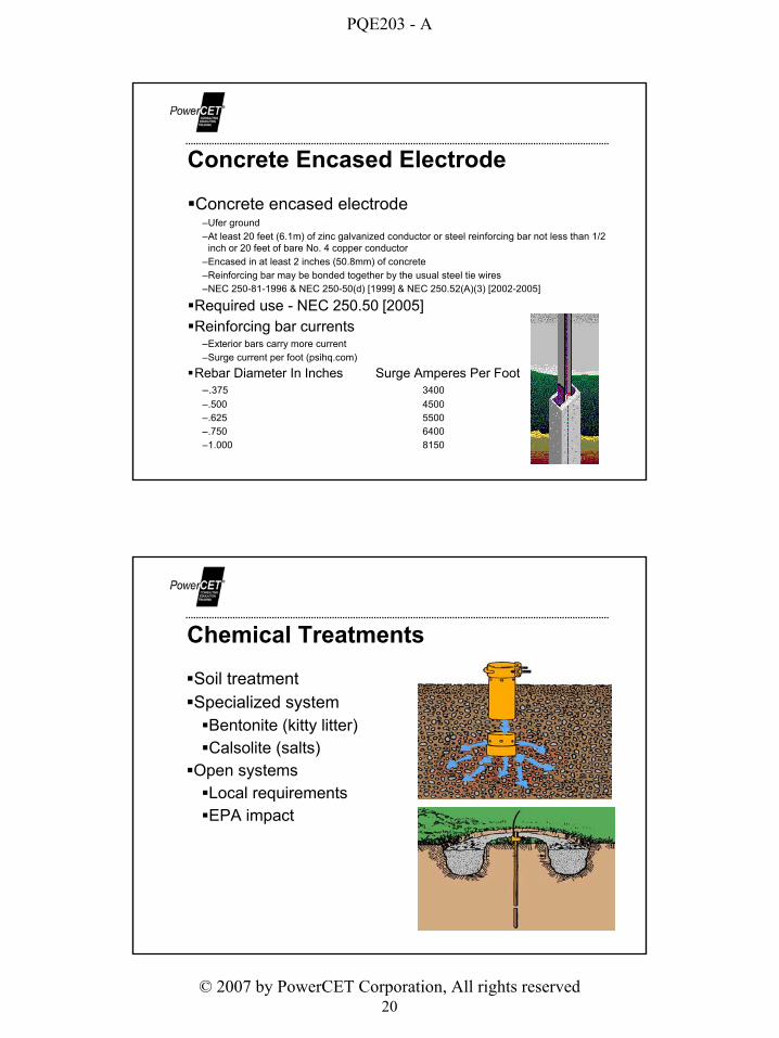
Chemical Treatments
Soil treatmentSpecialized system
Bentonite (kitty litter)Calsolite (salts)
Open systemsLocal requirementsEPA impact

PQE203 - A
© 2007 by PowerCET Corporation, All rights reserved21
Types of Grounding Electrodes
Driven ground rodsCopper clad steel
Plate electrodeTwo square feet minimum - 1/4 inch thick steel (6.35mm) - 21/2' depth
Ring groundGrounding conductor buried around building perimeter
Chemical groundsTraditional rod or ring with chemical treatmentSpecialized ground rod with integral chemical treatment
Ufer groundMetallic conductor embedded in structural concrete
ElectrolysisElectrochemical series Galvanic Battery
Aluminum (-1.67V)
Magnesium (-2.34V)
Iron (-0.44V)
Tin (-0.14)
Copper (+0.34V)
Stainless Steel
Gold (+1.42V)

PQE203 - A
© 2007 by PowerCET Corporation, All rights reserved22
Facility Grounding & Lightning
Lightning treatment –Bond ground terminals to GES
NEC 250-106 [1999 - 2005]–Air terminal conductors and ground terminals are not to be used in lieu of intended GES
NEC 250.60 [2005]–250.106 FPN 2
6' (1.83m) clear air spacing to conductive metalwork or 3' (0.92m spacing through wood, concrete or brick)
–NFPA 780-2004 (4.21.2) provides calculation for clearance from down conductors due to high voltage & ionization
Low impedance paths to earth
–Current density and path resistance determine voltage rise
–Low dc resistance does not guarantee effective current handling
–Surface radials may be most effective with sandy soil but well watered topsoil
–Lightning grounding systems bonded to electrical service and to facility structural steel
Effective Earth Terminals

PQE203 - A
© 2007 by PowerCET Corporation, All rights reserved23
Lightning Transient Characteristics
Return-stroke current–Unidirectional impulse (30 kA, 10 x 100 µs)–Continuing currents (100 A, 10 mS)
Non-connecting upward leaders–Bipolar impulse (100 A, 10 x 100 µs)
Induced currents–Unipolar & bipolar (10 A, 2 x 50 µs)
Self Inductance Vs Voltage Rise–30kA return stroke with 10 meter conductor length–Conductor inductance; 1uH per meter–Voltage rise; -V = Ldi/dt = 10E-06(30E03/10E-06) = 30,000V–Single conductor discharge path does not work!!!
Concrete FloorsConstruction practices often leave the steel reinforcing bars without grounding/bondingNEC 250.52(A)(3) [2005] Concrete-encased Electrode
"An electrode encased by at least 50mm(2in) of concrete, located within and near the bottom of a concrete foundation or footing that is in direct contact with the earth...reinforcing bars shall be permitted to be bonded together by the usual steel tie wires or other effective means."

PQE203 - A
© 2007 by PowerCET Corporation, All rights reserved24
Reinforced Concrete Construction
Steel Beam Construction

PQE203 - A
© 2007 by PowerCET Corporation, All rights reserved25
Metal Cladding & Framework
NEC 250.104(C) [2005]–Bonding of piping systems and exposed structural steel
–Exposed metal building framework that is not intentional or inherently grounded and likely to be energized must be grounded per NEC 250.64.
Multiple Building Power/GroundingNEC 250.32 [2002 - 2005] Common ac serviceIf no common grounding conductor extends between the buildings with multiple circuits then each building must have an established grounding electrode system with a separate neutral-to-ground bond in each building.If a common grounded and grounding conductor extends between the buildings, and multiple circuits exist then a grounding terminal will be required in the connected buildings and no individual neutral-to-ground bonds will be permitted in each additional building.If a single circuit extends to a second building and both grounded and grounding conductors extend to the second building then no ground terminal will be required and a neutral-to-ground bond cannot be established at the second building.
Vref1 Vref2