Embed Size (px)
DESCRIPTION
uuu
Citation preview
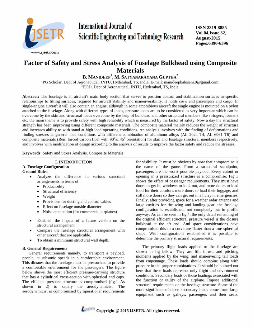
www.ijsetr.com
ISSN 2319-8885
Vol.04,Issue.32,
August-2015,
Pages:6390-6396
Copyright @ 2015 IJSETR. All rights reserved.
Factor of Safety and Stress Analysis of Fuselage Bulkhead using Composite
Materials B. MANIDEEP
1, M. SATYANARAYANA GUPTHA
2
1PG Scholar, Dept of Aeronautical, JNTU, Hyderabad, TS, India, E-mail: [email protected].
2HOD, Dept of Aeronautical, JNTU, Hyderabad, TS, India.
Abstract: The fuselage is an aircraft's main body section that serves to position control and stabilization surfaces in specific
relationships to lifting surfaces, required for aircraft stability and maneuverability. It holds crew and passengers and cargo. In
single-engine aircraft it will also contain an engine, although in some amphibious aircraft the single engine is mounted on a pylon
attached to the fuselage. Along with different types of loads, pressure loads are to be considered as very important which can be
overcome by the skin and structural loads overcome by the help of bulkhead and other structural members like stringers, formers
etc. the main theme is to provide safety with high reliability which is measured by the factor of safety. Now a day the structural
strength has been improving using different composite materials. The composite material mainly reduces the weight of structure
and increases ability to with stand at high load operating conditions. An analysis involves with the finding of deformations and
finding stresses at general load conditions with different combination of aluminum alloys (AL 2024 T4, AL 6061 T6) and
composite materials (Rein forced carbon fiber with 900& 45
0 orientation) for skin and fuselage structural members respectively,
and involves with modification of design according to the analysis of results to improve the factor safety and reduce the stresses.
Keywords: Safety and Stress Analysis, Composite Materials.
I. INTRODUCTION
A. Fuselage Configuration
Ground Rules:
Analyze the difference in various structural
arrangements in terms of:
Producibility
Structural efficiency
Weight
Provisions for ducting and control cables
Effect on fuselage outside diameter
Noise attenuation (for commercial airplanes)
Establish the impact of a future version on the
structural arrangement.
Compare the fuselage structural arrangement with
other aircraft that are applicable.
To obtain a minimum structural wall depth.
B. General Requirements General requirements namely, to transport a payload,
people, at subsonic speeds in a comfortable environment.
This dictates that the fuselage must be pressurized to provide
a comfortable environment for the passengers. The figure
below shows the most efficient pressure-carrying structure
that has a cylindrical cross-section with spherical end caps.
The efficient pressure structure is compromised (fig.1 As
shown in 2) to satisfy the aerodynamicist. The
aerodynamicist is compromised by operational requirements
for visibility. It must be obvious by now that compromise is
the name of the game. From a structural standpoint,
passengers are the worst possible payload. Every cutout or
opening in a pressurized structure is a compromise. Fig 3
shows the effect of passenger requirements. They must have
doors to get in, windows to look out, and more doors to load
food for their comfort, more doors to load their luggage, and
still more doors so they can get out in a hurry in emergencies.
Finally, after providing space for a weather radar antenna and
large cavities for the wing and landing gear, the fuselage
configuration is established, not completely but in profile
anyway. As can be seen in fig.4, the only detail remaining of
the original efficient structural pressure vessel is the closure
bulkhead at the aft end. And space considerations have
compromised this to a curvature flatter than a true spherical
shape. With configurations established it is possible to
determine the primary structural requirements.
The primary flight loads applied to the fuselage are
shown in fig below. They are lift, thrust, and pitching
moments applied by the wing, and maneuvering tail loads
from empennage. These loads should combine along with
pressure in the proper combinations. It should be pointed out
here that these loads represent only flight and environment
conditions. Secondary loads or those loadings associated with
the function or utility of the airplane. Impose additional
structural requirements on the fuselage structure. Some of the
more significant of those secondary loads come from large
equipment such as galleys, passengers and their seats,

B. MANIDEEP, M. SATYANARAYANA GUPTHA
International Journal of Scientific Engineering and Technology Research
Volume.04, IssueNo.32, August-2015, Pages: 6390--6396
baggage, and cargo, which must be restrained not only for
normal flight conditions, but in most cases for extreme
loadings imposed under crash conditions. The final
consideration in configuration design is the cross section for
passenger transport which is predominantly influenced by
passengers. Fig shows double lobe cross section to
Fig.1 .Typical double lobe cross-section.
Satisfy passengers on the upper lobe and use enough
room for cargo volume at the lower lobe. This cross section
is a common one for narrow body transport of 5 to 7 abreast
seats; more than 8 abreast usually go to a single circular cross
section.
B. Fuselage Detail Design Skin and Stringers: The largest single item of the fuselage
structure is the skin and its stiffeners. It is also the most
critical structure since it carries all loads due to shear,
fuselage bending, and torsion and cabin pressure. This
primary loads are carried by the fuselage skin and stiffeners
with frames spaced at regular intervals to prevent buckling
and maintain cross-section.
NOTE: that there has been very little change in the basic
structural concept, since the earliest metal stressed skin
airplanes, These skin or stiffeners combinations have proved
over the years to be light weight, strong structure that is
relatively easy to produce and maintain.
The most efficient structure is the one with the least
number of joints or splices, therefore skin panels are as large
as possible, limited only by available mill sizes. Stringers,
being rolled from strip stocks are limited in length by
manufacturing techniques. Single lap splices are typically
used for the longitudinal skin joints. This is the lightest
design and does not impose a severe aerodynamic penalty on
a subsonic airplane. The transverse splices, those normal to
the air stream, are flush-butt splices because a lap step here
would have an appreciable effect on boundary layer
turbulence and drag. Stringers splice locations are established
by another set of rules, since the skin and stringers are
working together; they should both be spliced at the same
location. This maintains the relative stiffness of the stringer
or skin combination, which is desirable from a fatigue stand
point.
Fig.2. Fuselage transverse splice of skin and stringer.
The fuselage cross section in the ideal shape is of a true
cylinder such as the L-1011,DC-10 and A300 transports, and
the cabin pressure loads are carried by hoop tension in the
skin with no tendency to change shape or induced frame
bending. The two most common fail-safe design concepts are
breaking the component down into several small overlapping
pieces where, if one fails, its loads can be carried by adjacent
parts, or utilizing a restrainers or fail-safe strap that will
contain a failure with incontrollable limits. The latter method
is applied in the skin of transport design where the critical
design loading is pressure.
Fig.3.Fail-safe strap located between skin and frame.
The above fig shows a typical skin, stringer, fail safe
strap, and frame attachment. The tear strap, which is riveted,
spot wielded or bonded to the skin, is sized such that a skin
crack mill stop when it reaches the strap and the strap can

Factor of Safety and Stress Analysis of Fuselage Bulkhead using Composite Materials
International Journal of Scientific Engineering and Technology Research
Volume.04, IssueNo.32, August-2015, Pages: 6390-6396
carry the load that the skin has given up. Tear straps are
located between each frame station Fig.4. It has been proved
by the test that a 20 to 40 inch crack can be sustained without
a catastrophic failure. In the areas where the skin thickness is
determined by bending loads, the stress level from hoop
tension is low enough that fatigue is not critical. The
discussion of skin, stringer, and fail-safe pressure design has
been somewhat short compared to its importance. Most
thought, study, and testing has gone into this phase of the
structure than any other because poor design details in this
area are uniform giving. Utilization of the airplane power
over shorter route segments means that fatigue is a primary
design consideration. The lower operating pressure
differential means the minimum gage skins could be used in
the hoop tension areas if a satisfactory design for fail safe
crack length control could be developed.
Fig.4.Waffle doubler design instead of fail-safe straps.
Fig.5.Effect of sidewall frame depth.
Shown are fuselage skins with doublers which are bonded
to the skin to extend fatigue life. Minimum thickness (0.036
inch) skins have a waffle pattern doubler bonded on them, a
plane product is the elimination of the stringer joggle where
the stringers have to step over individual fail-safe straps (or
tear straps) as shown in Fig.5. Examination of the various
typical fuselage configurations of commercial airplanes
reveal that they are basically similar combinations of the
skin-stringer-ring(frame) structures, with the interior trim line
(one inch greater than the frame depth)providing an overall
cabin wall thickness. Ring or frame spacing is in the order of
20 inches and stringers spacing varies between 6 to 10
inches. Commonly, the passenger transport fuselage sidewall
(window and door area) design replaces stringers with
heavier thickness skins so that a quieter cabin can be
obtained and the skin fatigue stress can be reduced because
of cabin pressurization cycles. In the sidewall region, frame
depth can be kept to a minimum (provided that adequate
working space is not a problem) because no significant
concentrated loads are involved. Above and below the side
wall region, ample space is available to profile for increased
frame depth as required. Another advantage is to reduce
fuselage diameter to save structural weight and less fuselage
frontal area to reduce aerodynamic drag with the same
internal width across.
Frames and Floor Beam: Fuselage frames perform many
diverse functions such as:
Support shell compression/ shear
Distribute concentrated loads
Fail-safe (crack stoppers).
They hold the fuselage cross section to control shape and
limit the column length of longerons of stringers as shown in
Fig.6. Frames also act as circumferential tear strips to ensure
fail-safe design
Fig.6. Typical floor beam arrangement.
In addition they distribute the external and internal loads
onto shell, redistribute shear across structural discontinuities,
and transfer loads at major joints. Heavy cabin frames and
bulkheads represent extremes in the matter of radial
constraint on the expansion of cabin shell. Owing to their
film sine conventional cabin frames, whose main function is
the preservation of the circular shape against elastic
instability under the compressive longitudinal loads, have
little constraint on the radial expansion of the shell.

B. MANIDEEP, M. SATYANARAYANA GUPTHA
International Journal of Scientific Engineering and Technology Research
Volume.04, IssueNo.32, August-2015, Pages: 6390--6396
C. Fuselage Loads Loads affecting fuselage design can result from flight
maneuvers, landings or ground handling conditions as shown
in Fig.7. Fuselage loads are primarily a problem of
determining the distribution of weight, tail loads, and nose
landing gear loads. Weight distribution is important because
a large part of fuselage loads stems from the inertia of mass
items acted upon by accelerations, both translational and
rotational. Tail loads, which are generally quite large,
contribute heavily to bending the aft portion of the fuselage.
Dissymmetry of tail loads causes significant aft-body
torsions. In the same sense that tail loads affect the aft-body,
loads acting on the nose landing gear will contribute
significantly to net loads on the forward portion of the
fuselage, the fore body. As implied above, the various
portions of the fuselage can be most critically loaded by
completely different flight or handling conditions. For
expedience of analysis the airplane is divided into three
sections and each of these is analyzed separately. Of course,
eventually the structure must be considered for effect of loads
carrying through from one section to the other. For
discussion here, the fuselage will be divided into sections in
the same manner as is generally applied in analysis. For a
typical airframe, the fuselage is divided into three sections.
Fig.7.Fuselage divided into three sections.
Fore body: that portion of the fuselage forward of
the forward main frame.
Aft body: that portion of the fuselage aft of the aft
main frame; including the empennage.
Center body: that portion of the fuselage between
main frames.
Distribution of Weight: The fuselage weight distribution
consists of the fixed weight of the structure and equipment,
and the removable load. The removable load in military types
is relatively small and concentrated. Passenger and cargo
airplanes, however, are required to carry loads of varying
quantity and location in the fuselage. Because of the various
possible arrangements of the cabin for different customers,
the removable load (cargo and passengers) is considered to
include such items as seats, galleys, lavatories, etc. An
arbitrary floor loading is then used for transport airplane
design. This arbitrary loading is selected to envelope all
possible variations of cabin loading. The floor loading for
this equipment plus passengers runs approximately 45 lb. per
sq. ft. Baggage weight is satisfactorily approximated by a
maximum of 20 lb. per cubic ft. of cargo space. The arbitrary
loading used is then distributed in the fuselage to obtain the
gross weights and center of gravity locations on the c.g.
envelope.
Fore Body Loads: The fore body loads incurred during
symmetrical flight are obviously in a vertical direction only;
there are no side loads. This vertical direction is normal to
the airplane reference axis, or in the "z" direction. These
vertical loads are determined simply by multiplying the
weight loads by the load factor. Vertical air loads are
generally neglected in fore body loads calculations except for
wide body fuselage or their effect on local structure.
Neglecting them is generally conservative because they are in
the direction to relieve inertia loads. Also, they are usually
small relative to net loads. Another reason contributing to
their omission is the fact that accurate distributions are
difficult to determine because of irregularities in the fuselage
profile. Good distributions would have to be determined by
wind tunnel pressure measurements. The cost involved is
usually not warranted. Assumed, linearized distributions are
sometimes used, but it should be borne in mind that the
probable inaccuracy, coupled with the relative magnitude of
the air load, results in a load component of questionable
reliability. Side loads (in the y direction) are caused by side
and yawing accelerations and air loads incurred during
unsymmetrical maneuvers. Here the air loads make up a large
part of the net loads and therefore cannot be neglected. As
reasonable a distribution as possible is estimated based on
best available data. Critical fore body loadings may also be
experienced from application of nose landing gear loads.
Design loadings might arise from landing or application of
main wheel brakes during taxiing, particularly unsymmetrical
brake application.
Aft Body Loads: Aft body vertical flight loads are a critical
combination of inertia loads and horizontal tail balancing
loads. The horizontal tail loads are determined for the various
conditions on the V-n diagram and center of gravity
locations. Since the distribution of weight in the fuselage as
well as the tail loads are a function of c.g. location, the
problem is one of determining the critical combinations.
Lateral loadings result from application of air loads acting on
the vertical tail in combination with side inertia loads. Air
loads on the fuselage aft body is generally neglected both in
the vertical and side directions. In this case the air loads are
not necessarily relieving; therefore it is not conservative to
neglect them. However, they are generally quite small, and
their distribution in the unpredictable flow behind the wing is
impossible to determine.
External Pressures: External pressures on the fuselage,
other than in wing vicinity, are usually significant only
around protuberances as shown in Fig.8. In the area of the
wing, the pressures on the wing are carried onto the fuselage.
The pressure on the fuselage will be of the order of
magnitude of the pressure on the wing.

Factor of Safety and Stress Analysis of Fuselage Bulkhead using Composite Materials
International Journal of Scientific Engineering and Technology Research
Volume.04, IssueNo.32, August-2015, Pages: 6390-6396
Fig.8.pressure distribution on fuselage.
Internal Pressures (Cabin Pressure): The fuselage internal
pressure depends on the cruise altitude and the comfort
desired for the occupants. Pressure differential may be
readily determined from the altitude charts as shown if the
actual altitude and the desired cabin pressure are known.
Fuselage pressurization is an important structural loading. It
induces hoop and longitudinal stresses in the fuselage which
must be combined with flight and ground loading conditions.
The important consideration for establishing the fuselage
design pressures is the cabin pressure differential or present
in altitude and the fuselage is designed to maintain.
Example: Assume an airplane
Provide an 8000 ft. altitude cabin pressure
The max Flight altitude at 43,000 ft.
The pressures used with flight and ground conditions on
the airplane are:
TABLE I: Pressure Conditions On Flight And Ground
In addition, a pressure of 1.33*8.85=11.75psi is considered
to act alone.
II. INITIAL SZING
A. Stringer Thickness Initial Sizing By Denis Howe’s
Method The method to estimate the initial size of stringer section
in Denis Howe’s book is:
The pitch of stringers is between 1.5 and 5 times the
stringer height, it is suggested that in the initial design
phase, this value can be assumed 3.5.
The width of stringer flanges can be estimated 40% of
the stringer height.
The thickness of stringer can be as same as the skin.
The width of flange is normally 16 times than its thickness
as shown in Fig.9.
Fig. 9.1initial sizing of Zed shape stringer.
B. Calculations of Skin Thickness Using Denis Howe’s
Methods Initial sizing of skin thickness using the condition of
pressurized skin:
(1)
Where
P2 –P1
P2 is the internal pressure of 0.1bar
P1 is the external pressure to be calculated
R - is the radius of the skin = 3.95m ( from table )
=allowable stress of standard value =100MN/m2
External pressure at 10,000 altitude is 0.2 bar (from
appendix) or 2.6550 104N/m2.
tp = 1.5 mm (approximately)
TABLE II: General Characteristics
TABLE III: Material Properties

B. MANIDEEP, M. SATYANARAYANA GUPTHA
International Journal of Scientific Engineering and Technology Research
Volume.04, IssueNo.32, August-2015, Pages: 6390--6396
Fig.10.fuselage structural assembly section view.
Fig.11. Fuselage Structural Assembly.
III. RESULTS & DISCUSSION
A. Results Before Modification
TABLE IV: Results of Static Analysis
TABLE V: Results of Modal Analysis
B. Results After Modification
Table VI: Results of Static Analysis
Table VII: Results of Modal Analysis
Fig.12.stress before modification.
The above table IV and V showing results for before and
after modification of design. By observing the data and stress
distribution it can be understood that the stress on the skin are
less, that means it has more strength than required, so we can
decrease the skin thickness to some extent and we can reduce
the structural weight as shown in Figs.10 to 12. Second one is
the bulkhead structure has shown more deformations than
skin so in order to increase the strength we have to increase
the thickness of the bulkhead structure. As a result of
modification the final results were tabulated in table V & VI
which are more satisfactory than the results before
modification. The analysis of results for different material
combination is shown in table VII.
Factor of Safety and Stress Analysis of Fuselage Bulkhead using Composite Materials
International Journal of Scientific Engineering and Technology Research
Volume.04, IssueNo.32, August-2015, Pages: 6390-6396
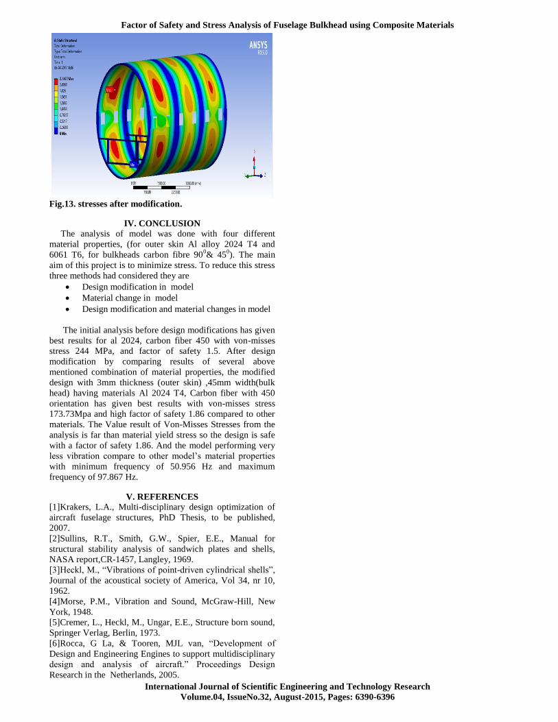
Fig.13. stresses after modification.
IV. CONCLUSION
The analysis of model was done with four different
material properties, (for outer skin Al alloy 2024 T4 and
6061 T6, for bulkheads carbon fibre 900& 45
0). The main
aim of this project is to minimize stress. To reduce this stress
three methods had considered they are
Design modification in model
Material change in model
Design modification and material changes in model
The initial analysis before design modifications has given
best results for al 2024, carbon fiber 450 with von-misses
stress 244 MPa, and factor of safety 1.5. After design
modification by comparing results of several above
mentioned combination of material properties, the modified
design with 3mm thickness (outer skin) ,45mm width(bulk
head) having materials Al 2024 T4, Carbon fiber with 450
orientation has given best results with von-misses stress
173.73Mpa and high factor of safety 1.86 compared to other
materials. The Value result of Von-Misses Stresses from the
analysis is far than material yield stress so the design is safe
with a factor of safety 1.86. And the model performing very
less vibration compare to other model’s material properties
with minimum frequency of 50.956 Hz and maximum
frequency of 97.867 Hz.
V. REFERENCES
[1]Krakers, L.A., Multi-disciplinary design optimization of
aircraft fuselage structures, PhD Thesis, to be published,
2007.
[2]Sullins, R.T., Smith, G.W., Spier, E.E., Manual for
structural stability analysis of sandwich plates and shells,
NASA report,CR-1457, Langley, 1969.
[3]Heckl, M., “Vibrations of point-driven cylindrical shells”,
Journal of the acoustical society of America, Vol 34, nr 10,
1962.
[4]Morse, P.M., Vibration and Sound, McGraw-Hill, New
York, 1948.
[5]Cremer, L., Heckl, M., Ungar, E.E., Structure born sound,
Springer Verlag, Berlin, 1973.
[6]Rocca, G La, & Tooren, MJL van, “Development of
Design and Engineering Engines to support multidisciplinary
design and analysis of aircraft.” Proceedings Design
Research in the Netherlands, 2005.