Embed Size (px)
Citation preview
QUEST RESEARCH JOURNAL, VOL. 18, NO. 1, PP. 1–10, JAN–JUN, 2020 1
Factors Affecting Operational Accuracy of Orifice Metering for Incompress-ible Fluids
Sikandar Almani1,2, Masroor Abro1, Kashif Hussain Mangi2,4, Imran Nazir Unar1,*, Abdul Basit Qazi3,Naveed Ali Koondhar1, Abdul Samee Memon1
1Department of Chemical Engineering, MUET, Jamshoro, Pakistan2GEPEA Laboratory, Universite de Nantes, 44602 Saint-Nazaire Cedex, France3Beijing University of Chemical Technology, Beijing, China4Department of Chemical Engineering, Quaid-e-Awam University of Engineering and Technology, Nawabshah, Pakistan*Corresponding author: [email protected]
Abstract
Flow measurement is the determination of the quantity of a fluid, either a liquid, or gas that passes through a pipe,duct, or open channel. In the physical world, engineers are frequently required to monitor or control the flow ofvarious fluids. Orifice metering is one of the prime and easy ways of measuring the flowrates. It has the versatileapplication of fluid measurement in various industries such as oil and gas sector, polymer, and beverages, etc. Thestudy presented in this paper is conducted to investigate mainly the variation in the measurement of flow discharge byaltering the geometrical specifications of the orifice plate. With this purpose, the fabrication of required orifice platesis accomplished in the mechanical workshop. Experimental work is done on Armfield Flow Meter Demonstration Unit.Using the application of Bernoulli’s equation, the calculations of the theoretical volumetric flowrate and coefficientof discharge are carried out. This attempt suggests that the proper design of the orifice plate is very important toachieve the highest possible level of flow metering accuracy. The findings also suggest its periodic maintenance toprevent abnormalities such as contamination, corrosion, etc. as these can cause a huge error in the measurementof volumetric discharge. The highest discharge coefficient (0.88) was of a plate having orifice diameter 2.3 cm andangle 450◦. Based on all the experimental findings, the uncontaminated orifice plate with beta ratio (0.54) andbevel angle of 45◦was recommended which resulted in the highest discharge coefficient leading to the maximumaccuracy. The proposed configuration can help industries at achieving the accurate flow metering which in turn canovercome the economic losses associated with flows.
Keywords—Orifice plate, flow metering, discharge coefficient, beta ratio, bevel angle
F
1 Introduction
Orifice flow measuring device is one of the mostprominent among all differential pressure mea-
suring devices. The orifice meter is widely used for flowmeasuring due to the wide range of applications, lowmaintenance, easy installation, and low capital cost [1].The performance of orifice differential pressure meterdepends on many parameters including properties ofthe fluid, location of orifice meter, and amount ofdischarge and contraction ratio. Various researchershave investigated extensively to optimize the effectof a different geometrical parameter such as orificediameter, bevel angle, shape, and direction of theorifice [2][3].Research has been carried out on the optimization
ISSN: 2523-0379 (Online), ISSN: 1605-8607 (Print)
and the effectiveness of orifice metering via experi-ments and numerical simulations with computationalfluid dynamics (CFD). Numerical simulations wereperformed using a circular orifice plate to investigatethe characteristics of the flow field. The effect ofturbulence at varying orifice beta ratio (ratio betweenorifice diameter to the pipi diameter) and Reynoldsnumber were studied. As per their findings, the staticwall pressure profile and center-line velocity of fluidwere slightly better as compared to other scheme usedin their simulation studies [4][5].Jianhua et. al. [6] performed a study on the effectiveparameters including the effect of head loss, the effectof contraction ratio, and the ratio of orifice platediameter and discharge pipe diameter. In additon,they also investigated the dimensionless length of the

QUEST RESEARCH JOURNAL, VOL. 18, NO. 1, PP. 1–10, JAN–JUN, 2020 2
recirculation region and the effect of Reynolds numberon the energy dissipation ratio. Numerical simulationsand physical model experiments were performed toget the relationship among the aforementioned men-tioned parameters. The head loss coefficient is primar-ily dominated by the contraction ratio and the ratioof the plate thickness by the effect of the length ofrecirculation. Later on, Shah et. al. [2] used OpenFOAM-1.6 solver in order to numerically investigatethe orifice flow pattern such as pressure recovery andvelocity profiles. The maximum pressure drop throughan orifice and flowrate of Re was between 4489 and9012.Orifice device is also used in literature for many flowtypes and nature of fluids such as Newtonian and non-Newtonian fluids [7-9]. Studies concerning the effect oforifice plates on pressure loss and discharge coefficienthave also been carried out. An experimental studywas carried out with non-Newtonian and Newtonianfluids under laminar flow conditions and turbulent flowregimes. In the laminar flow regime, the discharge coef-ficient increased with an increase in Reynolds number.Whereas, the discharge coefficient remained constantwhen turbulent flow conditions were used [10].Wang et. al. [11] studied the effect of orifice con-traction ratio with respect to the plate thickness toflood discharge tunnel diameter using different valuesof Re theoretically. The relationship was obtainedthrough the application of physical model experimentsin which lower wall pressure was mainly dominated bya contraction ratio of the orifice plate. Different en-gineering operations which involve piping systems useflow passage restriction. During the flow control, manytypes of control valves and orifices are used in orderto control pressure and flowrates. Particularly at anindustrial scale, accurate determination of flow charac-teristics, especially that of orifices, are very important.The control measures in the food processing industry,determination of high viscous liquids determine thequality of the product [12]. In pre-mixed combustion,single orifices are applied to increase the uniformityof flow distribution and in exchange of heat and masstransfer operations [13].Furthermore, the application of restricting orifices re-sults in severe erosion in the presence of solid particles,hydraulic loss inflow, cavitation in fluid flows, chokingin case of gas flows, vibration and noise. Orifice me-tering systems are carefully designed and applied incirculation pumps in order to avoid pump starvationand prevent cavitation in pumps. The geometry ofrestricting orifice may have one or multiple holes.The multi-hole type of restricting orifices are used toachieve a high discharge coefficient at lower pressure
drop [11].In some industrial applications, single orifice is notsufficient to get required pressure drop without facingany problem such as in gas flows choking of flow occurs,liquid flashes out when the single orifice is used, andhigh flow velocities result in severe erosion withinthe pipe. Multistage restricting orifice (MRO) is com-monly used in such cases in order to achieve the desiredpressure drop. The optimization of the geometry ofmultiple restricting orifice and effective configurationin the pipelines in cooling systems of power gener-ation units and some other process control systemsis mandatory [11]. As single stage restricting orificemay have single or multi-stage holes, similarly multi-stage restricting orifice may have single or multi-holeconfiguration or combination of both. Different holeconfigurations in restricting orifice are arranged. Itmay have an arrangement of concentric holes or eccen-tric holes which are configured diametrically oppositeto each other in the pipe. The flow field characteristicsin downstream of a single restricting orifice mainly reston the upstream situations as well as the diameterratio, fluid properties, velocity of the fluid, and onthe shape of orifice. Because of the alteration, inflowpassage geometry across the orifice plate and the flowof fluid experience sudden changes in flow turbulence[14]. whereas, in case if multi-stage restricting office,the flow through the orifice further becomes complexand aggravated when multi-stage orifices are arrangedclose to each other.In such combinations of geometries, the aggressivenature of fluid results in failures in oil, gas, andenergy transportation systems. The wide variety ofdegradation mechanisms is observed in such situationssuch as erosion-corrosion, cavitation erosion [15], flowaccelerated corrosion (FAC), and thermal fatigue [16].Sometimes, the complex configuration and improperhandling of flow lead to severe safety and reliabilityissues that cause huge economic loss and fatalities. Ex-perimental as well as numerical investigation are doneby many researchers on the characteristics of orificeflow by taking into account different parameters suchas inlet velocity of the fluid, size of the orifice plate,thickness of orifice plate, and size of the pipe fromwhich fluid flows. Ting et. al. [17] investigated differentoperating conditions on accurate measurement of flowthrough orifice. He did a bundle of experiments onreversed plates, bent plates, and surface roughness.According to his results, the flow from reversed plateswas low as compared to the actual flow from the orificeplates by 12% to 17%.All these studies reveal the significance of differentoperating and geometric factors on the orifice flow

QUEST RESEARCH JOURNAL, VOL. 18, NO. 1, PP. 1–10, JAN–JUN, 2020 3
Fig. 1: Flow meter demonstration unit
metering accuracy. The study presented in this paperis aimed at investigating the different characteristicfactors of the orifice plate and their significance interms of metering accuracy. To achieve this, orificeplates with different design considerations were fab-ricated and employed in experiments.
2 Material & MethodsThis part includes the experimental setup utilized forthe experiments, measurement of actual flowrate withdigital, analog and traditional flowmeters in order tohave a reference value of volumetric flowrate, fabri-cation of different orifice plates depending on theirgeometrical configuration and finally the experimentalprocedure for the determination of discharge coeffi-cient (Cd).
2.1 Experimental SetupThe experimental setup is mentioned as follows.
2.1.1 ApparatusThe Armfield C9 flow meter demonstration unit [18](Figure 1) available in the department of chemical en-gineering MUET, Jamshoro is a complete set of equip-ment designed to demonstrate the important featuresof six types of flow meters for measuring water flowin ducts or open channels, service modules with accu-mulator and pump. Turbine reference flow meter waspermanently installed for the different combination offlow experiments as per the research demand. The self-priming centrifugal pump pumps the water from thetank into the service module and distributes it intothe flow meter test pipe. The pressure drop in eachflow meter can be measured using a 0.5 meter pressuregauge or a 1 meter mercury gauge. A manometerconnection valve mounted to the orifice ensures thequick release of all the pressure gauge piping. The
installation allows air to enter the hydraulic flow todemonstrate the impact on meter accuracy. The dis-charge of the test section is controllable and entersthe passage of the GRP service module through thediffuser, where the notch ”Vee” and the rectangularnotch can be installed. The water discharged fromthe tested flow meter is collected in a volumetrictank where the flow can be determined absolutely.The tank is graduated to support high or low flowand is equipped with a static flow deflector to reduceturbulence. Telescopes and scales connected to the tapat the bottom of the volumetric tank allow immediatevisualization of the water level. The water is returnedto the collecting tank via the drain valve. The basesystem contains a reference flowmeter selected for itsreliability and accuracy.
2.1.2 Measurement of Actual FlowrateThe actual flow metering was performed through theinferential multi-stream flow meter and swinging flapmeter. Inferential multi-stream flow meter determinesthe flowrate through the drops of static pressure to thelimit of the pipe or rotation of the wheel or rotor in-stead of measuring the actual mass flow. To crosscheckthe accuracy of the above-mentioned flow meters,the conventionally used bucket-and-stopwatch methodwas also used. It gave the measurement with a lowstandard deviation of ±6% which could be attributedto human error. The flow metering mechanism throughinferential multi-stream flow meter and swinging flapmeter is as follows.
a) Inferential Multi-Stream Flow MeterA flow meter in which the flow is determined bymeasurement of a phenomenon associated withthe flow, such as a drop in static pressure at arestriction in a pipe, or the rotation of an impelleror rotor, rather than measurement of the actualmass flow.
b) Swinging Flap MeterThe flap-type meter includes a spring or swingingpattern of flow. It restores the internal flaps intheir original position. Sometimes, if the springis too tight, the incoming fluid will be limitedand if it is not fully open, the suction fluid speedincreases.
c) Bucket-and-Stopwatch MethodA bucket and a stopwatch is an analogy for theoperation of a positive displacement meter. Thestopwatch is started when the flow starts andstopped when the bucket reaches its limit. Thevolume divided by the time gives the flowrate. Forcontinuous measurements, a system that contin-uously fills and empties the bucket is needed to

QUEST RESEARCH JOURNAL, VOL. 18, NO. 1, PP. 1–10, JAN–JUN, 2020 4
Fig. 2: Various flow meters used
Fig. 3: Selection of meter for actual flow meter
distribute the flow without letting it out of thepipeline.
The measurement of actual flow was started by insert-ing a swinging flap meter. The valve opening of thepump was adjusted, so that it gives a reading of 100lit/m. This flow meter was inserted and dismantledmany times for the sake of accuracy. For the verifi-cation purpose, the other meters were also used. Inaddition, the traditional bucket-and-stopwatch tech-nique was also adopted and the final result of eachwas observed. The results are shown in the followingfigures. Lastly, the result of a swinging flap meter wastaken into consideration for processing work.
2.2 Fabrication of Orifice PlatesThe Armfield apparatus was provided with the provi-sion of replacing the orifice plates having same dimen-sions. This made it easy to determine the flowratesusing plates of different specifications. In continua-tion of it, we needed to fabricate the orifice plateshaving concentric, perforated, segmental and eccentricshapes. The required orifice plates were fabricated inmechanical engineering workshop at Mehran Univer-sity where a mild steel bar was cut into several pieces.
These pieces were shaped into the desired plate usinglathe machine. The material used for fabrication wasreadily to corrode when exposed to atmosphere, there-fore, it became necessary to take preventive measureslike galvanizing, chroming and oil painting. However,galvanizing was preferred to others for the mainte-nance of its design parameters such as bevel angle andorifice diameter. Different fabricated orifice along withtheir configuration are shown in Table 1.
2.3 ProcedureThe design of the experiments and the overall proce-dure is described in the following points.
• The tank was filled with portable water for con-tinuous circulation.
• The priming was performed by regulating the flowof water through the flow meter.
• The flowrate was maintained at 100 lit/min byadjusting the control valve (Figure 4).
• The flow meter was separated from the flow meterassembly.
• The orifice meter was inserted at the object point.• The head loss (h1-h2) was developed in a differ-
ential mercury manometer.• This head loss was utilized in the theoretical
discharge (Qth) formula.
Qth = A0[1 − (A0
A1)]−1/2[2g(h1 − h2)]1/2 (1)
• Several readings at different flowrates were taken.These values were fed to the observation table tofind the flowrates and coefficient of discharge.
• The conversion of head loss mmHg was convertedin mH2O with a correction factor 0.0126.
• The coefficient of discharge (Cd) was calculatedby the following expression.
Cd = Qact/Qth (2)
The aim of this study was to investigate thevariation in flowrates measured after the perfor-mance of experimental works using orifice platesof different specifications. This was achieved afterseveral experiments were carried out. The resultsof the different factors that affects the operationalaccuracy of orifice metering are given in Table 2.The effect of various factors affecting the accuracyof orifice metering is discussed below.
2.4 Effect of Orifice Diameter or Beta Ratio onMeasurement of FlowrateA large number of research papers were publishedabout the effect of orifice diameter on flowrate. Abd

QUEST RESEARCH JOURNAL, VOL. 18, NO. 1, PP. 1–10, JAN–JUN, 2020 5
S.No. Plate design Orifice Dia (cm) Pipe Dia(cm) Bevel Angle (Degree) Orifice’s actual view
1 Concentric 2.6 4.2 45◦
2 Concentric 2.3 4.2 45◦
3 Concentric 3.0 4.2 45◦
4 Concentric 2.6 4.2 30◦
5 Concentric 2.6 4.2 60◦
6 Concentric 2.6 4.2 0◦
7 Perforated 1.0 4.2 45◦
8 Segmental 4.2 4.2 0◦
9 Damaged 2.6 4.2 45◦
10 Eccentric 1.0 4.2 45◦
11 Concentric 2.3 4.2 45◦
12 Concentric 2.3 4.2 45◦
TABLE 1: Fabricated orifice plates along with their specification
Fig. 4: Actual flowrate
et. al. [19] investigated the performance of different
orifice diameters corresponding to different beta ratioand Reynolds number. This study shows that thedischarge coefficient (Cd) increases by increasing βwhen Re ≤ 9 × 10³ (laminar with respect to pipeflow). Whereas, this discharge coefficient decreaseswith increasing in β when Re ≤ 9 × 10³ (turbulentflow). Therefore, geometric parameters are required tobe properly designed in order to achieve the desiredobjective. It has also been found that the orifice dis-charge coefficient reduces with increasing in Reynoldsnumber for all values of the beta ratio, especially atthe turbulent flow regime.In the present study, three orifice plates each havingthe same bevel angle of 45◦, but a different orificediameter of 2.3, 2.6 and 3.0 cm having beta ratio 0.548,0.62, and 0.714 respectively were used separately and

QUEST RESEARCH JOURNAL, VOL. 18, NO. 1, PP. 1–10, JAN–JUN, 2020 6
Sr.No: PlateName
PlateDesign
DifferentialPressure
Actual (Q)lit/min
Theoretical (Qth)lit/min Cd
1
Actual plate
Bevel angle (45◦)
β ratio (0.62)
Concentric 54 100 129.7722 0.7706
Sr.No. Factor PlateDesign
DifferentialPressure
Actual (Q)lit/min
Theoretical (Qth)lit/min Cd
2β ratio 0.548 Concentric 68 100 112.6198 0.8879
3 0.714 Concentric 32 100 145.4668 0.68744
Bevel Angle30◦ Concentric 70 100 147.7522 0.6768
5 60◦ Concentric 74 100 151.6582 0.65946 0◦ Concentric 68 100 145.6263 0.68677
GeometricalChange
Perforated 166 100 127.7363 0.78298 Segmental 25 100 122.9897 0.81319 Damaged 43 100 141.3996 0.7072
10 Eccentric Out of the rangeof manometer —— —— ——
11 Inverted (Bevelfacing to upstream) Concentric 49 100 123.6186 0.8089
12 Contaminated Concentric 99 100 135.809 0.7363
TABLE 2: Results of each case
the theoretical discharge was measured. The resultsshow that increasing the beta ratio increases the the-oretical discharge which, at the same time, decreasesthe discharge coefficient (Cd). In the present study, therange of Re is between 5.69 × 10⁴ to 7.35 × 10⁴, whichis surely a turbulent flow.Results agrees the remarks in literature and the trendsbetween discharge coefficient, beta ratio and Reynoldsnumber. These results of beta ratio vs. the theoreticaldischarge and beta ratio vs. the discharge coefficientare shown in Figure 5a and 5b, respectively. The devi-ation in theoretical discharge from actual discharge bychanging orifice diameter suggests that a plate havingorifice diameter 2.3 cm (β = 0.548) is more accuratethan the other two.
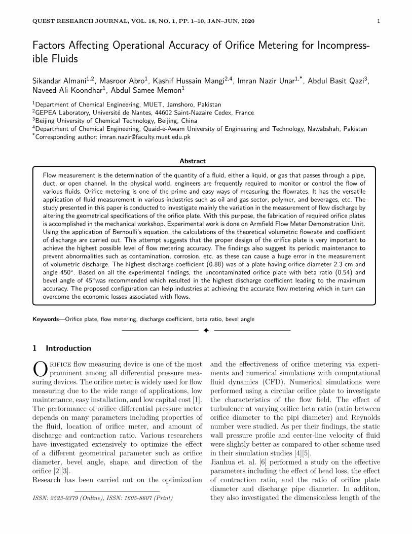
2.5 Effect of Orifice Bevel Angle on Measure-ment of FlowrateCollacott et. al. [20] tested different bevel angles be-tween 60◦-120◦. This study concluded that there isno significant effect of the bevel angle on flow mea-surement. Experimental investigations have confirmedthat the radius of the sharp edge of orifice plates hasa marked effect upon the discharge coefficient. On theother hand, local damage to the sharp edge needs tobe particularly severe before a significant change in thedischarge coefficient is detected [21].We investigated the effect of orifice bevel angle to getan insight into the suitable selection of its value forpractical applications. Therefore, four orifices plateswith the same orifice diameter (2.6 cm provided with
(a) beta ratio vs. theoretical discharge
(b) beta ratio vs. discharge coefficient
Fig. 5: Effect of orifice diameter or beta ratio on flowmeasurements
QUEST RESEARCH JOURNAL, VOL. 18, NO. 1, PP. 1–10, JAN–JUN, 2020 7
(a) Bevel angle vs. theoretical discharge
(b) Bevel angle vs. discharge coefficient
Fig. 6: Effect of bevel angle on flow measurements
the Armfield facility) but with different bevel angle of0◦, 30◦, 45◦and 60◦were used to investigate the effectof bevel angle on flow measurements. The results de-picted in Figure 6(a,b) show that an orifice plate witha bevel angle of 45◦resulted in the highest accuracyto approach actual discharge, however, in the rangeof other bevel angle values, an insignificant differencein discharge was obtained. Figure 6a shows that thenearer value to actual discharge is obtained by using aplate with a bevel angle of 450. It is also evident fromFigure 6b that the orifice with 450 has the highestCd among others. These results are similar to thosereported in the relevant literature.
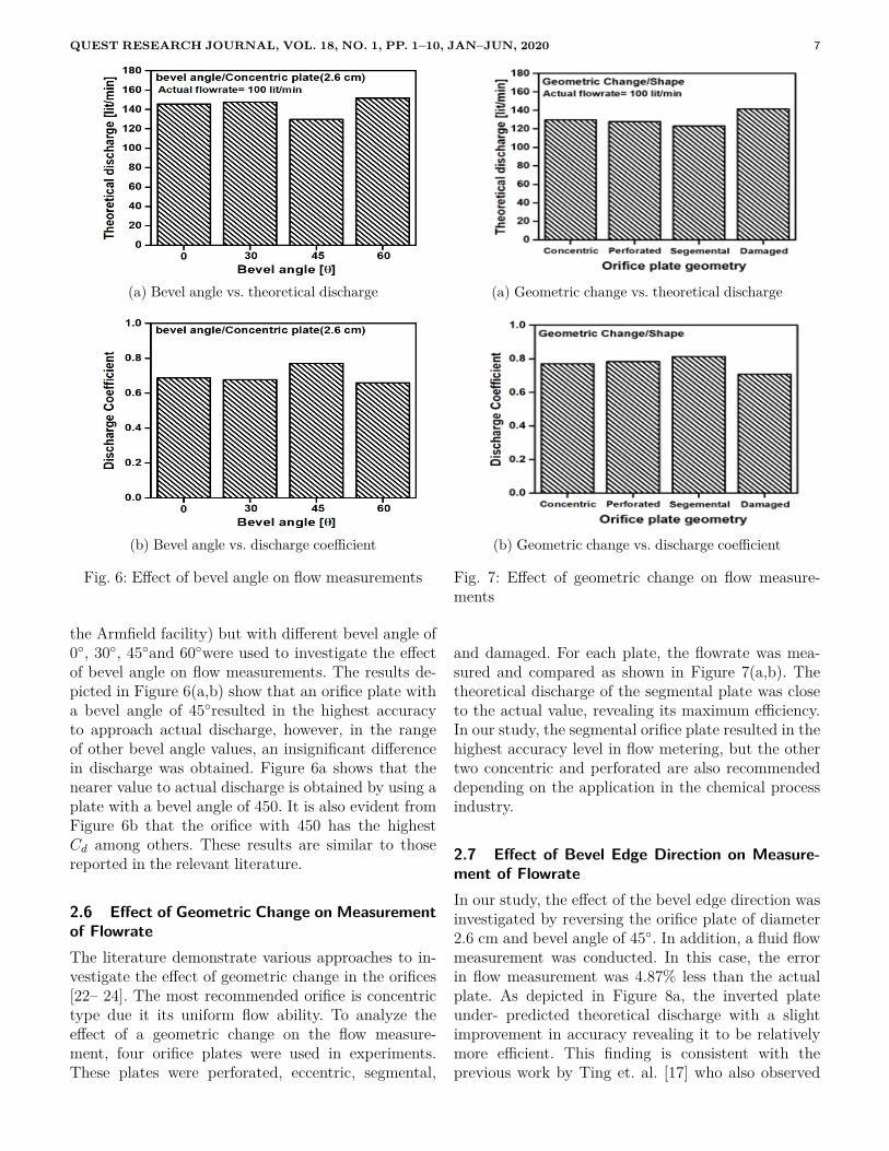
2.6 Effect of Geometric Change on Measurementof FlowrateThe literature demonstrate various approaches to in-vestigate the effect of geometric change in the orifices[22– 24]. The most recommended orifice is concentrictype due it its uniform flow ability. To analyze theeffect of a geometric change on the flow measure-ment, four orifice plates were used in experiments.These plates were perforated, eccentric, segmental,
(a) Geometric change vs. theoretical discharge
(b) Geometric change vs. discharge coefficient
Fig. 7: Effect of geometric change on flow measure-ments
and damaged. For each plate, the flowrate was mea-sured and compared as shown in Figure 7(a,b). Thetheoretical discharge of the segmental plate was closeto the actual value, revealing its maximum efficiency.In our study, the segmental orifice plate resulted in thehighest accuracy level in flow metering, but the othertwo concentric and perforated are also recommendeddepending on the application in the chemical processindustry.
2.7 Effect of Bevel Edge Direction on Measure-ment of FlowrateIn our study, the effect of the bevel edge direction wasinvestigated by reversing the orifice plate of diameter2.6 cm and bevel angle of 45◦. In addition, a fluid flowmeasurement was conducted. In this case, the errorin flow measurement was 4.87% less than the actualplate. As depicted in Figure 8a, the inverted plateunder- predicted theoretical discharge with a slightimprovement in accuracy revealing it to be relativelymore efficient. This finding is consistent with theprevious work by Ting et. al. [17] who also observed

QUEST RESEARCH JOURNAL, VOL. 18, NO. 1, PP. 1–10, JAN–JUN, 2020 8
(a) Bevel edge direction vs. theoretical discharge
(b) Bevel edge direction vs. discharge coefficient
Fig. 8: Effect of change in bevel edge direction
the reduction in flow metering error by the magnitudeof 14 to 17% when reversed orifice plate was used.Figure 8b shows the change in discharge coefficientwith respect to the change in bevel edge direction.
2.8 Effect of Contamination on Measurement ofFlowrateContamination is the deposition of grease, oil, anddirt in an orifice plate which produces hindrance inflow and can increase the bevel angle. Due to this, thevariation in orifice flow measurement occurs. A platewith an orifice diameter of 2.3 cm was contaminatedby gluing a thick and non-uniform layer of lubricanton the downstream face of the orifice plate. As shownin Figure 9(a,b), accumulation of contamination onthe orifice plate leads to an increased flow meteringerror. The results demonstrate that the maintenanceof orifice plates via cleaning them with ethanol or anyother alcoholic solution is highly recommended, be-cause the contamination by oil, grease or other stickingmaterials can decrease the discharge coefficient thatwill have certain influence on the economic factors inthe industry.
(a) Effect of contamination on theoretical dis-charge
(b) Effect of contamination on discharge coeffi-cient
Fig. 9: Effect of contamination on flow measurements
Fig. 10: Discharge coefficient of various plates
2.9 Discharge Coefficient of Various PlatesDischarge Coefficient (Cd) is the ratio of actual totheoretical discharge, calculated by using Equation 2.Figure 10 depicts the value of (Cd) for all plates. Thehighest discharge coefficient (0.88) was of a plate hav-

QUEST RESEARCH JOURNAL, VOL. 18, NO. 1, PP. 1–10, JAN–JUN, 2020 9
ing an orifice diameter of 2.3 cm and angle 45◦. Basedon all the experimental findings, the uncontaminatedorifice plate with beta ratio 0.54 and bevel angle of45◦was recommended which resulted in the highestdischarge coefficient leading to maximum accuracy.The proposed configuration can help industries atachieving the accurate flow metering which, in turn,can overcome the economic losses associated withflows.
3 ConclusionThere is a variety of applications of orifice metering inthe measurement of compressible and incompressiblefluids in various industrial sectors. The importance oforifice metering cannot be ignored at all and for aparticular orifice meter, a particular design criterionmust be followed. While fabricating an orifice plate,all the standards involved in its design must be underconsideration. A properly designed orifice plate givesthe best level of accuracy. A minor deviation fromthe proper design may yield a substantial variationin flow measurement. Already, many researchers havecontributed to observe the effects of various factorson the accuracy of the orifice meter. In continuationof that, our research work also gives similar results.Changing various specifications of the orifice plateslightly changes the result. The obtained results sug-gest that the design criteria of the orifice should begiven importance and minor change in the specifica-tion should not be ignored.Oil and gas industries such as SNGPL and SSGCin Pakistan are suppliers of natural gas. They mayface a huge economic loss in case of an error in flowmeasurement by orifice meter. The proper mainte-nance and cleaning of orifice meter assembly must bedone in order to avoid contamination effect in orificemetering. We, in our experimental work, have shownthat there is a huge deviation in fluid measurement ifthe orifice plate is contaminated. As the intensity ofcontamination increases, the deviation also follows thesame pattern. If all aspects are fulfilled such as designcriteria, maintenance, and cleaning, the orifice meterwill give efficient and satisfactory results.In future, CFD simulations will be carried out for thiswork in order to analyze the flow fields and vortexmechanisms in flow, especially near the orifice plate.
AcknowledgementThis work is from the bachelor’s thesis of SikandarAlmani, Abdul Basit Qazi, and Naveed Ali Koondhar.The authors would like to thank Mr. Fayyaz, lathemachine operator at MUET Jamsoro, for fabricating
the orifice plates very precisely/accurately accordingto the factors under this study.
References[1] F. Shan, Z. Liu, W. Liu, and Y. Tsuji, “Effects of the orifice
to pipe diameter ratio on orifice flows,” Chem. Eng. Sci.,vol. 152, pp. 497–506, 2016.
[2] M. S. Shah, J. B. Joshi, A. S. Kalsi, C. S. R. Prasad, and D.S. Shukla, “Analysis of flow through an orifice meter: CFDsimulation,” Chem. Eng. Sci., vol. 71, pp. 300–309, 2012.
[3] W. Ai and J. Wang, “ScienceDirect Minimum wall pressurecoefficient of orifice plate energy dissipater,” Water Sci.Eng., vol. 8, no. 1, pp. 85–88, 2015.
[4] S. Eiamsa-ard, A. Ridluan, P. Somravysin, P. Promvonge,and N. Chok, “Numerical investigation of turbulent flowthrough a circular orifice,” KMITL Sci. J, vol. 8, no. 1, 2008.
[5] R. K. Singh, S. N. Singh, and V. Seshadri, “Performanceevaluation of orifice plate assemblies under non-standardconditions using CFD,” Indian J. Eng. Mater. Sci., vol. 17,pp. 397–406, 2010.
[6] U. Fratino & A. Pagano, “Head loss coefficient of orificeplate energy dissipator,” J. Hydraul. Res., vol. 49, no. 2011,pp. 830–831, 2011.
[7] G. Rasool, T. Zhang, A. Shafiq, H. Durur, “Influence OfChemical Reaction on Marangoni Convective Flow of Nano-liquid in the Presence of Lorentz Forces and Thermal Radia-tion: A Numerical Investigation,” J. Adv. Nanotechnol., vol.1, no. 1, pp. 32–49, 2019.
[8] K. A. Abro, I. A. Abro, S. M. Almani, and I. Khan, “On thethermal analysis of magnetohydrodynamic Jeffery fluid viamodern non-integer order derivative,” J. King Saud Univ. -Sci., vol. 31, no. 4, pp. 973–979, 2019.
[9] M. Khahledi, R. Haldenwang, R. Chhabra, and V. Fester,“Non-Newtonian fluid flow from the bottom of the tankusing orifices of different shapes,” Chem. Eng. Res. Des.,vol. 157, pp. 34–45, 2020.
[10] S. B. Nicholas. AkhazeMusa and Bobai, “Determinationof Orifice Coefficients for Flow-Through Circular and Rect-angular Orifices,” J. Sci. Technol. Educ., vol. 6, no. 1, pp.188–197, 2018.
[11] H. Wang, X. Shujuan, S. Qingyi, Z. Caimin, L. Hao, and C.Eryun, “Experiment study on pressure drop of a multistageletdown orifice tube,” Nucl. Eng. Des., vol. 265, pp. 633–638,2013.
[12] M. Vi, T. Gronych, M. Je, L. Peksa, J. Wild, and F. Stan,“Experimental study of gas flow through a multi-openingorifice,” Vacuum, vol. 86, pp. 1759–1763, 2012.
[13] M. K. Roul, “Flow Through Thin and Thick Orifices inHorizontal Pipes,” J. Fluids Eng. Trans. ASME, vol. 134,no. September 2012, pp. 1–14, 2014.
[14] H. P. Rani, T. Divya, R. R. Sahaya, V. Kain, and D. K.Barua, “Numerical investigation of energy and Reynoldsstress distribution for a turbulent flow in an orifice,” Eng.Fail. Anal., vol. 34, pp. 451– 463, 2013.
[15] K. M. Hwang, “Cause Analysis for the Wall Thinning andLeakage of a Small Bore Piping Downstream of an Orifice,”Corros. Sci. Technol., vol. 12, no. 5, pp. 227–232, 2013.
[16] J. Xiong, X. Cheng, and Y. Yang, “International Journalof Heat and Mass Transfer Numerical investigation on masstransfer enhancement downstream of an orifice,” Int. J.Heat Mass Transf., vol. 68, pp. 366–374, 2014.
[17] V. C Ting, “Effects of Nonstandard Operating Conditionson the Accuracy of Orifice Meters,” SPE, Chevron Pet.Technol. Co, no. February, 1993.

QUEST RESEARCH JOURNAL, VOL. 18, NO. 1, PP. 1–10, JAN–JUN, 2020 10
[18] H. Rotary et al., “Armfield C9 – Flow Meter Demonstra-tion Unit,” pp. 20–24.
[19] H. M. Abd, O. R. Alomar, and I. A. Mohamed, “Effects ofvarying orifice diameter and Reynolds number on dischargecoefficient and wall pressure,” Flow Meas. Instrum., vol. 65,no. January, pp. 219–226, 2019.
[20] R. A. Collacott, “Discharge Coefficients of ChamferedOrifices and Nozzles,” Aircr. Eng. Aerosp. Technol., vol. 20,no. 4, pp. 112–113, 1948.
[21] J. M. Hobbs and J. S. Humphreys, “The effect of orificeplate geometry upon discharge coefficient,” Flow Meas.Instrum., vol. 1, no. 3, pp. 133–140, 1990.
[22] F. A. Flachskampf, A. E. Weyman, J. L. Guerrero, andJ. D. Thomas, “Influence of orifice geometry and flow rateon effective valve area: An in vitro study,” J. Am. Coll.Cardiol., vol. 15, no. 5, pp. 1173–1180, 1990.
[23] H. Yu, P. Zhu, J. Suo, and L. Zheng, “Investigation of Dis-charge Coefficients for Single Element Lean Direct InjectionModules,” Energies, vol. 11, no. 6, 2018.
[24] M. M. A. Alam, T. Setoguchi, S. Matsuo, and H. D. Kim,“Nozzle geometry variations on the discharge coefficient,”Propuls. Power Res., vol. 5, no. 1, pp. 22–33, 2016.