Embed Size (px)
Citation preview
V1.021809
BAKER FACTORY 6 KICKER INSTALLATION INSTRUCTIONS
Factory 6‐Speed Kicker kit
678-HR-K Shown
V1.021809
PAGE 2| OVERVIEW
BAKER FACTORY 6 KICKER INSTALLATION INSTRUCTIONS
FEATURES
• 6061 T-6 Aluminum Billet Bearing Door in Show Polish, Raw Finish, Black Finish • 6061 T-6 Aluminum Billet Side Cover in Show Polish • Modern Clutch Actuation Available in Ball and Ramp Cable Type or Hydraulic • Hardened 8620 Kicker Gears • 4140 Pinion Gear Quill With Smooth Micro Finish For Superior Function • Hardened 8620 Ratchet Hub Encapsulates Mainshaft To Prevent Breaking • Straight Stainless steel kick arm with 5/8” 4140 spindle and bronze kicker pedal
PART NUMBERS/DESCRIPTIONS
• 678-MR-K; F6K w/ silver door & polished cover, cable type
• 678-HR-K; F6K w/ silver door & polished cover, hydraulic type
• 678-MB-K; F6K w/ black door & polished cover, cable type
• 678-HB-K; F6K w/ black door & polished cover, hydraulic type
• 678-MP-K F6K w/ polished door & cover, cable type
• 678-HP-K; F6K w/ polished door & cover, hydraulic type
APPLICATION
• 2007-2009 Softails™, FLT/FLH™ • 2006 Dyna™ Models • Factory Cruise Drive 6 Speeds
NOTES
• BAKER™ Factor 6 Kicker will not clear stock exhaust systems due to the extended length of the transmission door and kicker. Aftermarket systems with
• The kicker arm will not clear the stock right side passenger floor board on FLT/FLH™ models. Installation of foot pegs or smaller footboards are required.
• Twin Cam models require installation of a cam-based ignition. See BAKER 2008-2009 Supplement for ignition alternatives or consult a BAKER sales tech.
• Fuel injected models require retrofit to carburetor retrofit
V1.021809
PAGE 3| TABLE OF CONTENTS
BAKER FACTORY 6 KICKER INSTALLATION INSTRUCTIONS
TABLE OF CONTENTS:
2) Overview, Part Numbers and Application 3) Table Of Contents
4) F6K exploded view & parts list, Cable type 5) F6K exploded view & parts list, Cable type, continued 6) F6K exploded view & parts list, Hydraulic type
7) F6K exploded view & parts list, Hydraulic type, continued
8) Getting Started, Tools and Resources
9) Gearset Removal / Bearing Door Disassembly
10) Bearing Door Disassembly Continued
11) Bearing Door Assembly
12) Bearing Door Assembly Continued 13) Gearset Installation/Side Cover Installation
14) Kick-arm Installation/Final Assembly
15) Terms and Warranty Conditions
16) Disclaimer and Customer Support
V1.021809
PAGE 4| EXPLODED VIEW: MECHANICAL CABLE TYPE
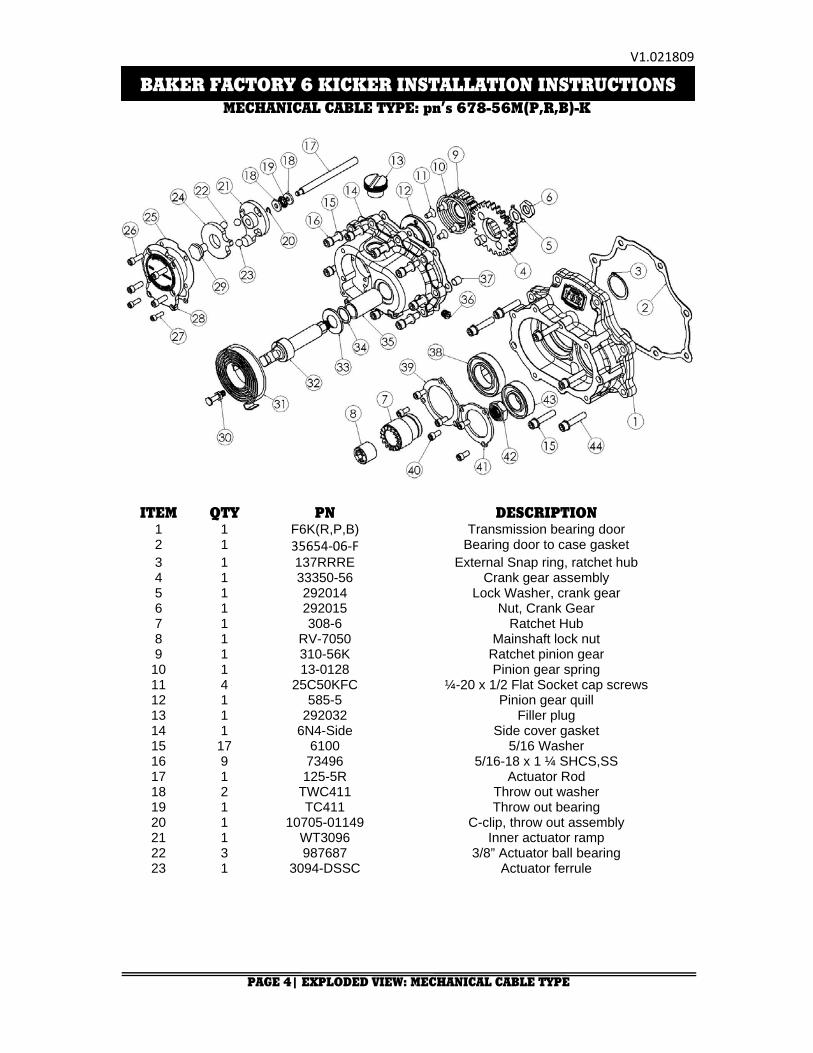
MECHANICAL CABLE TYPE: pn’s 678-56M(P,R,B)-K
BAKER FACTORY 6 KICKER INSTALLATION INSTRUCTIONS
ITEM QTY PN DESCRIPTION 1 1 F6K(R,P,B) Transmission bearing door 2 1 35654‐06‐F Bearing door to case gasket 3 1 137RRRE External Snap ring, ratchet hub 4 1 33350-56 Crank gear assembly 5 1 292014 Lock Washer, crank gear 6 1 292015 Nut, Crank Gear 7 1 308-6 Ratchet Hub 8 1 RV-7050 Mainshaft lock nut 9 1 310-56K Ratchet pinion gear
10 1 13-0128 Pinion gear spring 11 4 25C50KFC ¼-20 x 1/2 Flat Socket cap screws 12 1 585-5 Pinion gear quill 13 1 292032 Filler plug 14 1 6N4-Side Side cover gasket 15 17 6100 5/16 Washer 16 9 73496 5/16-18 x 1 ¼ SHCS,SS 17 1 125-5R Actuator Rod 18 2 TWC411 Throw out washer 19 1 TC411 Throw out bearing 20 1 10705-01149 C-clip, throw out assembly 21 1 WT3096 Inner actuator ramp 22 3 987687 3/8” Actuator ball bearing 23 1 3094-DSSC Actuator ferrule

V1.021809
PAGE 5| EXPLODED VIEW: MECHANICAL CABLE TYPE
BAKER FACTORY 6 KICKER INSTALLATION INSTRUCTIONS
MECHANICAL CABLE TYPE: pn’s 678-M(P,R,B)-K
ITEM QTY PN DESCRIPTION 24 1 WT3196 Outer Actuator Ramp 25 1 587-56M Ball ramp cover gasket 26 4 25C50KLHS ¼-20 x ½ Low head cap screw 27 2 10C50KLHS #10-24 x ½ Low head cap screw 28 1 584-56M Ball ramp cover plate 29 1 588-56M Actuator assembly bolt 30 1 292013 Kicker return spring bolt 31 1 291222 Spring, kick arm return 32 1 292003 Shaft, kicker 33 1 292016 Washer, kick shaft 34 1 9452K29 O-ring, kicker shaft 35 1 6391K269 Bushing, kicker shaft 36 1 51740-001 3/8-24 Drain plug 37 2 16583-00 10mm dowels 38 1 6007 Mainshaft bearing 39 1 407-RV07 Retainer Plate, Mainshaft 40 6 24050 ¼-20 x 5/8 BHCS 41 1 406-RV07 Retainer Plate, Countershaft 42 1 37141 Nut, countershaft retainer 43 1 6304 Countershaft bearing 44 8 31C150KCSS/P 5/16-18 x 1 ½ SHCS,SS
V1.021809
PAGE 6| EXPLODED VIEW: HYDRAULIC TYPE
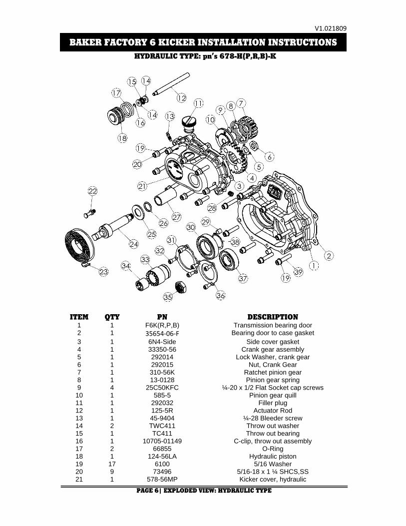
HYDRAULIC TYPE: pn’s 678-H(P,R,B)-K
BAKER FACTORY 6 KICKER INSTALLATION INSTRUCTIONS
ITEM QTY PN DESCRIPTION 1 1 F6K(R,P,B) Transmission bearing door 2 1 35654‐06‐F Bearing door to case gasket 3 1 6N4-Side Side cover gasket 4 1 33350-56 Crank gear assembly 5 1 292014 Lock Washer, crank gear 6 1 292015 Nut, Crank Gear 7 1 310-56K Ratchet pinion gear 8 1 13-0128 Pinion gear spring 9 4 25C50KFC ¼-20 x 1/2 Flat Socket cap screws
10 1 585-5 Pinion gear quill 11 1 292032 Filler plug 12 1 125-5R Actuator Rod 13 1 45-9404 ¼-28 Bleeder screw 14 2 TWC411 Throw out washer 15 1 TC411 Throw out bearing 16 1 10705-01149 C-clip, throw out assembly 17 2 66855 O-Ring 18 1 124-56LA Hydraulic piston 19 17 6100 5/16 Washer 20 9 73496 5/16-18 x 1 ¼ SHCS,SS 21 1 578-56MP Kicker cover, hydraulic
V1.021809
PAGE 7| EXPLODED VIEW: HYDRAULIC TYPE
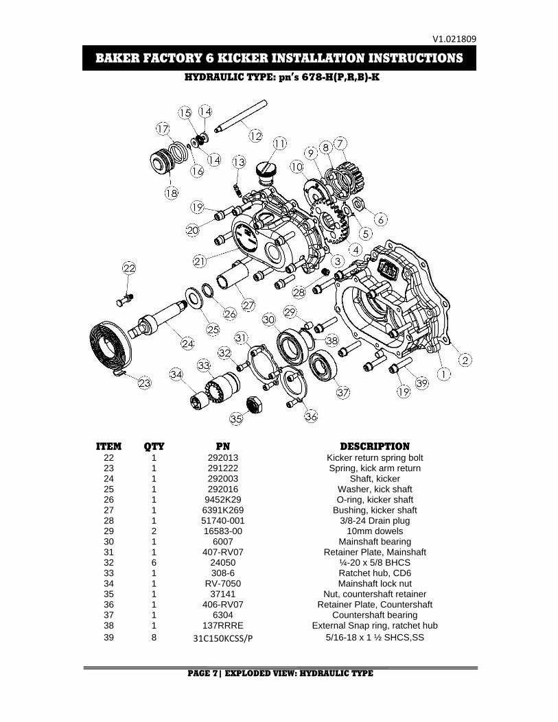
HYDRAULIC TYPE: pn’s 678-H(P,R,B)-K
BAKER FACTORY 6 KICKER INSTALLATION INSTRUCTIONS
ITEM QTY PN DESCRIPTION 22 1 292013 Kicker return spring bolt 23 1 291222 Spring, kick arm return 24 1 292003 Shaft, kicker 25 1 292016 Washer, kick shaft 26 1 9452K29 O-ring, kicker shaft 27 1 6391K269 Bushing, kicker shaft 28 1 51740-001 3/8-24 Drain plug 29 2 16583-00 10mm dowels 30 1 6007 Mainshaft bearing 31 1 407-RV07 Retainer Plate, Mainshaft 32 6 24050 ¼-20 x 5/8 BHCS 33 1 308-6 Ratchet hub, CD6 34 1 RV-7050 Mainshaft lock nut 35 1 37141 Nut, countershaft retainer 36 1 406-RV07 Retainer Plate, Countershaft 37 1 6304 Countershaft bearing 38 1 137RRRE External Snap ring, ratchet hub 39 8 31C150KCSS/P 5/16-18 x 1 ½ SHCS,SS

V1.021809
PAGE 8| GETTING STARTED
BAKER FACTORY 6 KICKER INSTALLATION INSTRUCTIONS
GETTING STARTED
The BAKER™ Factory 6 Kicker kit is designed to be easily installed by any competent mechanic or dealership technician. Having your H-D™ factory service manual is required in this installation as it is referred to in many sections of the instructions. While this kit is made to be as easy as possible to install there is no substitution for experience. To install the F5K kit, disassembly of the transmission down to the gearset is required. We recommend reading through these instructions, to the end, before proceeding with installation process.
TOOLS, RESOURCES, REQUIRED PARTS
• Factory Service Manual For Your Motorcycle • Factory Parts Manual For Your Motorcycle • Common Hand Tools Are All That Is Needed For This Installation • BAKER™ TOOLB-56 • Hydraulic Press • In-lbs Torque Wrench • Brake Bleeder Pump (for hydraulic type) FOR HYDRAULIC VERSION ONLY
• Hydraulic Fluid, BAKER™ Recommends: H-D™ Dot 5 Brake Fluid, pn 99902-77
• AN -3 Brake Line • 10mm Banjo Fitting for both ends of brake line • 3/8”-24 Banjo Bolt for the side cover end of the brake line • Banjo Fitting Washers • 11/16” Diameter Bore Hydraulic Clutch Lever Assembly

V1.021809
PAGE 9| DISASSEMBLY /TEAR DOWN
BAKER FACTORY 6 KICKER INSTALLATION INSTRUCTIONS
DISASSEMBLY/TEAR DOWN
Whereas it may seem we are skimming over many of the steps, your factory service manual will lay out in detail the proper methods for removal and reassembly of the components listed out in the steps within these instructions. Softails, Dynas and FLT/FLHs are all different configurations and require a different order and method to accomplish the various steps.
WITH ANY DRIVETRAIN RELATED PROJECT, THE FIRST STEPS THAT YOU WANT TO TAKE
ARE TO REMOVE THE SEAT AND DISCONNECT THE BATTERY FOR YOUR SAFETY.
Start with draining your transmission and primary lubricants. Refer to your Factory Service Manual for your drain plug locations.
Now remove the saddle bags, (if applicable), floorboards/foot controls and the exhaust system. Remove your starter. Remove your entire primary unit including outer primary, primary chain, clutch and inner primary. Use ToolB-56, Inner Race Service Tool, to pull the race off of the mainshaft. This needs to be done to remove gearset.
Loosen and remove the transmission side cover at this time. Remove the clutch cable from the side cover. The side cover and ball and ramp assembly will not be re-used in the BAKER™ Factory 6 Kicker.
REMOVE THE TRANSMISSION DIPSTICK AT THIS TIME; YOU CAN NOT REMOVE THE GEARSET
WITH IT INSTALLED
Remove the transmission top cover. Use your top cover gasket per the Factory Service Manual to act as a pad to rest the shifter pawl on while removing your gearset.
Using a 1‐1/16” 6 pt socket, you need to loosen the nylock jam nuts on both the countershaft and mainshaft before you remove the gearset from the case. A good trick is to stand with you right foot on the rear brake pedal while trying to loosen the jam nuts with a breaker bar.
Now you can unbolt the trap door from the case. Lightly tap on the end of the mainshaft on the primary side with a rubber mallet to loosen the entire gearset and trap door from the case and the 6th main needle bearings. You do not need to loosen the drive sprocket or remove the 6th main bottle gear to install this kit.
DO NOT HIT THE END OF THE MAINSHAFT WILL A BALL PEEN HAMMER, OR ANY
OTHER METAL HEADED HAMMER. HITTING THE MAINSHAFT WITH A GREAT AMOUNT
FORCE IN ANY MANNER, WITH ANY HAMMER, WILL DAMAGE THE THREADS. YOU
MUST REUSE YOUR STOCK MAINSHAFT AND WANT TO TAKE GREAT CARE NOT TO
DAMAGE IT IN ANYWAY. IF YOU FEEL THAT YOU DO NEED TO USE A GREAT DEAL OF
FORCE TO REMOVE THE GEARSET, STOP AND LOOK OVER ALL OF YOUR PREVIOUS
STEPS AS YOU MAY HAVE FORGOTTEN TO REMOVE A BOLT, THE MAINSHAFT BEARING

V1.021809
PAGE 9| DISASSEMBLY /TEAR DOWN
RACE, MOVED THE SHIFTER PAWL OR SOME OTHER SOLID OBJECT IS IMPEDING THE
PATH OF THE GEARSET BEFORE YOU PROCEED.
V1.021809
PAGE 10| DISASSEMBLY /TEAR DOWN CONTINUED
BAKER FACTORY 6 KICKER INSTALLATION INSTRUCTIONS
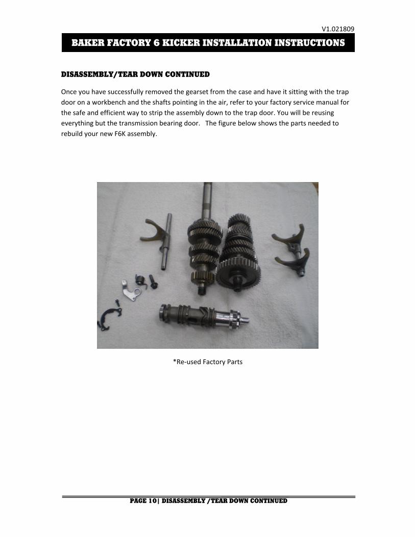
DISASSEMBLY/TEAR DOWN CONTINUED
Once you have successfully removed the gearset from the case and have it sitting with the trap door on a workbench and the shafts pointing in the air, refer to your factory service manual for the safe and efficient way to strip the assembly down to the trap door. You will be reusing everything but the transmission bearing door. The figure below shows the parts needed to rebuild your new F6K assembly.
*Re‐used Factory Parts

V1.021809
PAGE 11| BEARING DOOR ASSEMBLY
BAKER FACTORY 6 KICKER INSTALLATION INSTRUCTIONS
BEARING DOOR ASSEMBLY
1.) Remove the Factory 6 Kicker bearing door (pn F6K(P,R,B)) from the package. Clean your mainshaft and counter shaft threads with lacquer thinner and dry completely before pressing. Now take your countershaft assembly and support it vertically in the press with the threaded end facing up. Insure that the split securing segments are still in place. Now take your Factory 6 Kicker (pn F6K(P,R,B)) bearing door assembly and press the countershaft into the bearing (pn 6304). Use the bearing’s inner race as the press point. Make sure your countershaft is perfectly vertical before pressing it in, damage to threads could incur if not vertical. Remove assembly from press. Apply thread ‘Red’ thread lock to the countershaft retainer nut (pn 37141) and torque to 45-55 ft/lbs.
*Countershaft Assembly Pressed In 2.) Take the mainshaft assembly with the clutch end facing down. Make sure the split
securing segments are still in place and place the mainshaft in the press supported vertically. Now take the bearing door assembly and place it on to the mainshaft over the ratchet hub (pn 308-6). Once the mainshaft is parallel with the countershaft and the gears mesh, start pressing using the ratchet hub (pn 308-6) as the press point. Slowly press the mainshaft into the bearing door making sure all the gears spin freely. Once the mainshaft is seated, clean the threads with lacquer thinner and blow dry completely. Apply ‘Red’ thread lock to the mainhaft retainer nut (pn RV-7050) and torque to 45-55 ft/lbs. Your bearing door assembly is complete.
*Mainshaft and Countershaft Assembly Pressed In

V1.021809
PAGE 12| BEARING DOOR ASSEMBLY
BAKER FACTORY 6 KICKER INSTALLATION INSTRUCTIONS
BEARING DOOR ASSEMBLY CONTINUED
3.) You need to refer to your Factory Service Manual to finish the door assembly. Install the shift drum, shift forks, shift fork rods and detent pawl to the Factory Service Manual.
4.) Your gearset is now complete. Now is a good time to give your gearset a once over to make sure all the gears spin freely and are seated properly.
*Completed F6K bearing Door Assembly
V1.021809
PAGE 13| GEARSET INSTALLATION/KICKER COVER INSTALLATION
BAKER FACTORY 6 KICKER INSTALLATION INSTRUCTIONS
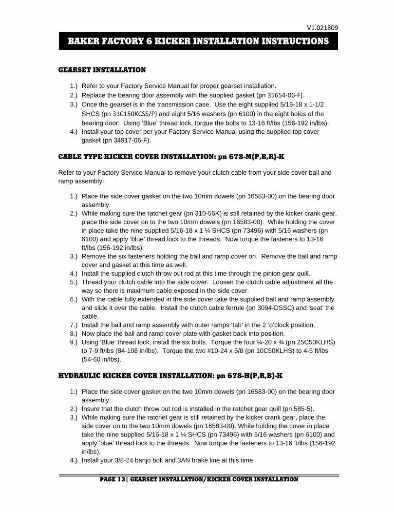
GEARSET INSTALLATION
1.) Refer to your Factory Service Manual for proper gearset installation. 2.) Replace the bearing door assembly with the supplied gasket (pn 35654‐06‐F). 3.) Once the gearset is in the transmission case. Use the eight supplied 5/16-18 x 1-1/2
SHCS (pn 31C150KCSS/P) and eight 5/16 washers (pn 6100) in the eight holes of the bearing door. Using ‘Blue’ thread lock, torque the bolts to 13-16 ft/lbs (156-192 in/lbs).
4.) Install your top cover per your Factory Service Manual using the supplied top cover gasket (pn 34917-06-F).
CABLE TYPE KICKER COVER INSTALLATION: pn 678-M(P,B,R)-K
Refer to your Factory Service Manual to remove your clutch cable from your side cover ball and ramp assembly.
1.) Place the side cover gasket on the two 10mm dowels (pn 16583-00) on the bearing door assembly.
2.) While making sure the ratchet gear (pn 310-56K) is still retained by the kicker crank gear, place the side cover on to the two 10mm dowels (pn 16583-00). While holding the cover in place take the nine supplied 5/16-18 x 1 ¼ SHCS (pn 73496) with 5/16 washers (pn 6100) and apply ‘blue’ thread lock to the threads. Now torque the fasteners to 13-16 ft/lbs (156-192 in/lbs).
3.) Remove the six fasteners holding the ball and ramp cover on. Remove the ball and ramp cover and gasket at this time as well.
4.) Install the supplied clutch throw out rod at this time through the pinion gear quill. 5.) Thread your clutch cable into the side cover. Loosen the clutch cable adjustment all the
way so there is maximum cable exposed in the side cover. 6.) With the cable fully extended in the side cover take the supplied ball and ramp assembly
and slide it over the cable. Install the clutch cable ferrule (pn 3094-DSSC) and ‘seat’ the cable.
7.) Install the ball and ramp assembly with outer ramps ‘tab’ in the 2 ‘o’clock position. 8.) Now place the ball and ramp cover plate with gasket back into position. 9.) Using ‘Blue’ thread lock, install the six bolts. Torque the four ¼-20 x ¾ (pn 25C50KLHS)
to 7-9 ft/lbs (84-108 in/lbs). Torque the two #10-24 x 5/8 (pn 10C50KLHS) to 4-5 ft/lbs (54-60 in/lbs).
HYDRAULIC KICKER COVER INSTALLATION: pn 678-H(P,R,B)-K
1.) Place the side cover gasket on the two 10mm dowels (pn 16583-00) on the bearing door assembly.
2.) Insure that the clutch throw out rod is installed in the ratchet gear quill (pn 585-5). 3.) While making sure the ratchet gear is still retained by the kicker crank gear, place the
side cover on to the two 10mm dowels (pn 16583-00). While holding the cover in place take the nine supplied 5/16-18 x 1 ¼ SHCS (pn 73496) with 5/16 washers (pn 6100) and apply ‘blue’ thread lock to the threads. Now torque the fasteners to 13-16 ft/lbs (156-192 in/lbs).
4.) Install your 3/8-24 banjo bolt and 3AN brake line at this time.

V1.021809
PAGE 14| GEARSET INSTALLATION/KICKER COVER INSTALLATION
BAKER FACTORY 6 KICKER INSTALLATION INSTRUCTIONS
KICK ARM INSTALLATION
1.) Install the kick arm on to the kicker crank gear shaft. 2.) Tighten the pinch bolt on the kicker crank gear shaft so that there is no sloppy movement
in the kicker arm assembly. 3.) Either with your hand or leg, ‘kick’ the kick arm and run it through its motion to make sure
everything is working properly.
FINAL ASSEMBLY
1.) Install your primary and adjust your clutch per your Factory Service Manual at this time. 2.) With the bike vertical fill your transmission with the supplied 32oz. bottle of Spectro™
75W140. 3.) Follow your Factory Service Manual to finish assembly on your motorcycle. 4.) Your BAKER™ Factory 6 Kicker installation is complete.
V1.021809
BAKER FACTORY 6 KICKER INSTALLATION INSTRUCTIONS
TERMS:
SPECIALORDERS
A minimum $500 deposit is required with all special orders. Special orders include unique case finishes, unique side door requests (i.e.; wrinkle black door or no logo).
ALL OTHER ORDERS
Orders can be pre-paid using VISA, MasterCard or American Express.
Prices shown are F.O.B. Haslett; MI. BAKER™ provides free UPS ground shipping on all retail orders for complete transmissions or transmission kit. UPS air shipment is available upon request. Customer is responsible for air shipment premiums.
LIMITED WARRANTY
BAKER™ Inc. transmission assemblies, transmission kits, and wide tire kits are guaranteed to the original purchaser to be free of manufacturing defects in materials and workmanship for a period of 2 years from the date of purchase.
If the product is found by BAKER™ to be defective, such products will, at the option of BAKER™, be replaced or repaired at cost to BAKER™.
In the event warranty service is required, the original purchaser must call or write BAKER™ immediately with the problem.If it is deemed necessary for BAKER™ to make an evaluation to determine whether the transmission assembly or transmission kit is defective, the entire transmission assembly, whether originally purchased as an assembly or kit, must be properly packaged and returned prepaid to BAKER™ with a copy of the original invoice of purchase.If after an evaluation has been made by BAKER™ and a defect in materials and/or workmanship is found, BAKER™ will, at BAKER™ option, repair or replace the defective part of the assembly.Warranty card must be returned within 45 days of purchase to be valid.
ADDITIONALWARRANTY PROVISIONS This limited warranty does not cover labor or other costs or expenses incidental to the repair and or replacement of BAKER™ products. This warranty does not apply if one or more of the following situations is judged by BAKER™ to be relevant: improper installation, accident, modification (including but not limited to use of unauthorized parts), racing, high performance application, mishandling, misapplication, neglect (including but not limited to improper maintenance), or improper repair.
BAKER™ shall not be liable for any consequential or incidental damages arising out of or in connection with a BAKER™ transmission assembly, transmission kit, swingarm, fender, component or part. Consequential damages shall include without limitation, loss of use, income or profit, or losses sustained as the result of injury (including death) to any person or loss of or damage to property.
BAKER™ transmissions, transmission kits, and Wide Tire Kits are designed exclusively for use in Harley-Davidson® motorcycles. BAKER™ shall have no warranty or liability obligation if a BAKER™ part is used in any other application.
If it is determined that a BAKER™ transmission assembly has been disassembled during the warranty period for any reason, this limited warranty will no longer apply.
PAGE 15| TERMS AND CONDITIONS
V1.021809
BAKER FACTORY 6 KICKER INSTALLATION INSTRUCTIONS
DISCLAIMER
The words Harley™ and H-D™ are registered trademarks and are for reference only. Use of H-D™ model designations and part numbers are for reference only. BAKER™ Drivetrain has no association with, and makes no claim against, these words, trademarks, or companies.
It is the sole responsibility of the user to determine the suitability of this product for his or her use, and the user shall assume all legal, personal injury risk and liability and all other as well as all other obligations, duties and risks associated therewith.
CUSTOMER SUPPORT
For any installation or service questions, please contact our BAKER technical department toll free: 1-877-640-2004.
Baker Drivetrain 9804 E. Saginaw Haslett, MI. 48840
On the web:
www.bakerdrivetrain.com
PAGE 16| DISCLAIIMER