Embed Size (px)
Citation preview

8/17/2019 FactoryTalk® View Machine Edition User's Guide
http://slidepdf.com/reader/full/factorytalk-view-machine-edition-users-guide 1/587
Performance and Visibility
FactoryTalk® View Machine Edition User's GuideUser's Guide

8/17/2019 FactoryTalk® View Machine Edition User's Guide
http://slidepdf.com/reader/full/factorytalk-view-machine-edition-users-guide 2/587
8/17/2019 FactoryTalk® View Machine Edition User's Guide
http://slidepdf.com/reader/full/factorytalk-view-machine-edition-users-guide 3/587
Rockwell Automation Publication - VIEWME-UM004L-EN-E – March 2016 3
Table of contents
About the documentation................................................................................... 29
Find the information you need .......................................................................... 29
Try the User's Guide and Help first ........................................................... 29
Find information on the Internet ............................................................... 30
Contact Rockwell Automation Technical Support ................................ 30
Legal Notices ......................................................................................................... 31
Chapter 1
Review operating system requirements ............................................................. 35
The parts of FactoryTalk View Machine Edition ........................................... 36
Additional software ....................................................................................... 36
The FactoryTalk View Machine Edition tools................................................ 36
FactoryTalk View Studio tools ................................................................... 36
Diagnostics Viewer ........................................................................................ 38
FactoryTalk tools ........................................................................................... 38
FactoryTalk Activation Manager ............................................................... 38
Chapter 2
Start and exit FactoryTalk View Studio ........................................................... 39
Start FactoryTalk View Studio ................................................................... 39
Exit FactoryTalk View Studio ..................................................................... 39
Open sample applications ................................................................................... 40
To open the InstantFizz_ME sample application ................................... 40
Problems opening applications ................................................................... 40
To set up write access for any Windows Security Group ....................... 41
Explore the FactoryTalk View Studio main window ..................................... 41
The menu bar ................................................................................................. 42
The toolbar ..................................................................................................... 42
The Explorer window ................................................................................... 42
The workspace ............................................................................................... 42
The Diagnostics List ..................................................................................... 43
The status bar ................................................................................................. 44
Workbook tabs ............. ........... .......... ........... ........... .......... ........... .......... ....... 44
Show and hide items in the main window ................................................ 45
Use the Explorer window .................................................................................... 45
View the Explorer window ................ ........... .......... ........... .......... ........... ..... 46
Move and resize the Explorer window ....................................................... 47
Work with editors .............. .......... ........... .......... ........... .......... ........... .......... ......... 47
Locate editors ................................................................................................. 47
Preface
Get Started
Explore FactoryTalk View
Studio
8/17/2019 FactoryTalk® View Machine Edition User's Guide
http://slidepdf.com/reader/full/factorytalk-view-machine-edition-users-guide 4/587
Table of contents
4 Rockwell Automation Publication - VIEWME-UM004L-EN-E – March 2016
View an editor's components .......... .......... ........... .......... ........... .......... ......... 48
Open editors ................................................................................................... 48
Close editors ................................................................................................... 49
Enter information in spreadsheets ..................................................................... 49 To enter information in a cell in a spreadsheet ........................................ 50
To move to the next cell in the row ............................................................ 50
To move to the first cell in the next row ................................................... 50
To delete a cell’s contents ............................................................................. 50
To delete rows ................................................................................................ 51
Print ........................................................................................................................ 51
To print an editor’s contents ....................................................................... 51
Select a printer ................................................................................................ 51
Print at runtime ............................................................................................. 52
Chapter 3
Understand the process ....................................................................................... 53
Collect data ............................................................................................................ 54
Design an HMI tag database ............................................................................... 54
Collect information ...................................................................................... 54
Organize tags .................................................................................................. 54
Plan graphic displays ............................................................................................ 55
Develop a hierarchy of displays ................................................................... 55
Create a template to ensure consistency .................................................... 56
Design displays ............................................................................................... 56
Plan languages........................................................................................................ 57
Plan alarms ............................................................................................................. 58
Provide information for the operator ............................................................... 58
Local and information messages ................................................................. 58
Diagnostics messages ..................................................................................... 59
Plan trends ............................................................................................................. 59
Plan recipes ............................................................................................................ 59
Design a secure system ......................................................................................... 60
Chapter 4
What is an application? ............. ........... .......... ........... ........... .......... ........... .......... 61
Application versus project ............................................................................ 61
HMI project file ............................................................................................. 62
Runtime application file ............................................................................... 62
Component files ............................................................................................ 62
External folders .............................................................................................. 62
Plan applications
Work with applications
8/17/2019 FactoryTalk® View Machine Edition User's Guide
http://slidepdf.com/reader/full/factorytalk-view-machine-edition-users-guide 5/587
Table of contents
Rockwell Automation Publication - VIEWME-UM004L-EN-E – March 2016 5
Default log file locations for MobileView, PanelView Plus 7, PanelViewPlus 6, PanelView Plus, PanelView Plus Compact, or PanelView PlusCE applications .............................................................................................. 63
Name files ....................................................................................................... 64 Create, import, open, and close applications ................................................... 64
Create an application .................................................................................... 64
Import an application ................................................................................... 66
Open an application ...................................................................................... 69
Open multiple applications ......................................................................... 71
Open and edit applications from earlier versions of RSView orFactoryTalk View ME .................................................................................. 72
Close an application ...................................................................................... 72
Rename, copy, delete, back up, and restore applications ............................... 73
To start the Application Manager tool, do one of the following .......... 73
About project settings .......................................................................................... 73
Project window size and runtime screen resolution ................................ 73
PanelView Plus 7 Standard applications and Compact Machine Editionapplications ..................................................................................................... 77
Title bar ........................................................................................................... 77
Specify project settings ......................................................................................... 79
View application properties .......... .......... ........... ........... .......... ........... .......... ....... 79
To view application properties .................................................................... 79
View HMI server properties ........... .......... ........... .......... ........... .......... ........... ..... 80
To view HMI server properties ................................................................... 80
Chapter 5
About data servers ................................................................................................ 81
About OPC communications ............................................................................ 81
Create data servers ................................................................................................ 82
Set up RSLinx Enterprise data servers ....................................................... 82
Set up an OPC data server ........................................................................... 83
Update data server caches ............................................................................ 84
Set up communications ....................................................................................... 84
Chapter 6
Types of tags .......................................................................................................... 87
Data server tags .............................................................................................. 87
HMI tags ......................................................................................................... 88
The data source .............................................................................................. 88
Basic steps for using tags ............................................................................... 88
Set up communications
Work with tags
8/17/2019 FactoryTalk® View Machine Edition User's Guide
http://slidepdf.com/reader/full/factorytalk-view-machine-edition-users-guide 6/587
Table of contents
6 Rockwell Automation Publication - VIEWME-UM004L-EN-E – March 2016
Use tag names that don’t exist ..................................................................... 89
When to use data server tags ........... .......... ........... .......... ........... .......... ........... ..... 89
Eliminate duplication ................................................................................... 89
Use complex data ........................................................................................... 89 Steps for using data server tags ........................................................................... 89
When to use HMI tags .................. .......... ........... ........... .......... ........... .......... ....... 90
Scale, offset, or provide a range for data ..................................................... 90
Store values in FactoryTalk View memory ............................................... 91
Steps for using HMI tags ..................................................................................... 91
Browse for tags ...................................................................................................... 91
To open the Tag Browser ............................................................................. 91
Use the Tag Browser ............................................................................................ 92
Show server names ......................................................................................... 93
Browse for off-line tags ........................................................................................ 93
Use tags and expressions in your application ................................................... 94
Assign tags ....................................................................................................... 95
Assign tags to graphic objects ...................................................................... 95
Use expressions to manipulate tag values .................................................. 96
Substitute tag names used in graphic objects ............................................ 97
Log tag values ......................................................................................................... 97
Use macros to assign values to tags .................................................................... 98
Chapter 7
HMI tag types........................................................................................................ 99
Analog tags that use floating-point values ............................................... 100
How values are rounded ............................................................................. 100
Use the Tags editor ............................................................................................. 101
Update the contents of the Tags editor ................................................... 101
Search for HMI tags .................................................................................... 102
Data sources ......................................................................................................... 104
Device ............................................................................................................ 104
Memory ......................................................................................................... 104
Address syntax for device tags ........................................................................... 104
Example: Logix5000 addressing ................................................................ 105
Organize HMI tags ............................................................................................. 106
Name tags ...................................................................................................... 106
Use folders to group tags ............................................................................ 107
View tag statistics .......... ........... .......... ........... ........... .......... ........... .......... ........... . 107
To view tag statistics ................................................................................... 107
Other methods for creating HMI tags ............................................................ 107
Create tags as needed in other FactoryTalk View editors .................... 108
Use HMI tags
8/17/2019 FactoryTalk® View Machine Edition User's Guide
http://slidepdf.com/reader/full/factorytalk-view-machine-edition-users-guide 7/587
Table of contents
Rockwell Automation Publication - VIEWME-UM004L-EN-E – March 2016 7
Create tags as needed in the Data Log Models editor ........................... 108
Import tags from a PLC database .................................................................... 109
To open the Import PLC Tags dialog box, do one of the following .. 109
Use the Tag Import and Export Wizard ........................................................ 110 To start the wizard, do one of the following ........................................... 110
Chapter 8
About global connections ................................................................................. 111
Set up global connections .................................................................................. 112
Update the date and time .................................................................................. 112
Update the date and time at the data source from the terminal ......... 113
Update the date and time at the terminal from the data source ......... 113
Change displays ................................................................................................... 114
Control display changes remotely............................................................. 114
Remote display changes and security ....................................................... 114
Set up remote display changes ................................................................... 114
Print displays ....................................................................................................... 115
Close On Top displays ....................................................................................... 115
Apply parameters to changed displays ............................................................ 116
Run macros .......................................................................................................... 116
Set up backlight intensity remotely ................................................................. 116
Monitor runtime RAM usage .......................................................................... 117
Chapter 9
About alarms ....................................................................................................... 119
Multiple language alarm messages ............................................................ 120
Other multiple language alarm features................................................... 120
Steps for setting up alarms................................................................................. 120
Prepare to set up alarms ..................................................................................... 121
Tags and expressions ................................................................................... 121
Identify alarm conditions ........................................................................... 121
Import and export alarm setup files ......................................................... 122
How alarms work ................................................................................................ 122
Alarm triggers and trigger values ............................................................... 122
Filter alarm triggers in multiple languages .............................................. 122
Alarm notification methods ...................................................................... 123
Show alarm information ............................................................................ 124
Interact with alarms .................................................................................... 125
The alarm log file ......................................................................................... 128
Alarm trigger data types ..................................................................................... 129
Set up global connections
Set up alarms
8/17/2019 FactoryTalk® View Machine Edition User's Guide
http://slidepdf.com/reader/full/factorytalk-view-machine-edition-users-guide 8/587
Table of contents
8 Rockwell Automation Publication - VIEWME-UM004L-EN-E – March 2016
The Value trigger type ................................................................................ 129
The Bit trigger type ..................................................................................... 130
The Least Significant Bit (LSBit) trigger type ........................................ 131
Tips for using array tags ..................................................................................... 133 Equivalent data types .................................................................................. 133
RSLinx Enterprise tag syntax ..................................................................... 134
KEPServer Enterprise tag syntax .............................................................. 134
Create alarm messages in multiple languages ................................................. 135
Optional alarm connections ............................................................................. 135
Connections that work with a specific alarm trigger.................................... 135
How the Handshake connection works .................................................. 136
How the Ack connection works ............................................................... 136
How the Remote Ack connection works ................................................ 137
How the Remote Ack Handshake connection works .......................... 138
Ensure alarm messages are read by the data source before sending newmessages ................................................................................................................ 139
Methods of alarm message handshaking ................................................. 139
Hold the message for a specific period of time ....................................... 139
Hold the message until the data source acknowledges that it has readthe message .................................................................................................... 140
How messages are queued .......................................................................... 140
How the Message connection works ........................................................ 141
How the Message Notification connection works ................................ 141
How the Message Handshake connection works .................................. 141
Connections that apply to all alarms ............................................................... 141
How the Silence connection works .......................................................... 142
How the Remote Silence connection works .......... ........... .......... ........... . 142
How the Remote Ack All connection works.......................................... 143
How the Status Reset connection works ................................................. 143
How the Remote Status Reset connection works.................................. 143
How the Close Display connection works .......... .......... ........... .......... ..... 143
How the Remote Close Display connection works .............................. 144
The [ALARM] display ...................................................................................... 144
The alarm banner graphic object .............................................................. 144
Buttons on the [ALARM] display ............................................................ 145
The [ALARM BANNER] display .................................................................. 145
The alarm banner graphic object .............................................................. 145
Buttons on the [ALARM BANNER] display ........... .......... ........... ........ 145
The [ALARM MULTI-LINE] display .......................................................... 145
The alarm list graphic object ..................................................................... 146
Buttons on the [ALARM MULTI-LINE] display .......... ........... .......... 146
The [STATUS] display ..................................................................................... 146
The alarm status list graphic object .......................................................... 147
8/17/2019 FactoryTalk® View Machine Edition User's Guide
http://slidepdf.com/reader/full/factorytalk-view-machine-edition-users-guide 9/587
Table of contents
Rockwell Automation Publication - VIEWME-UM004L-EN-E – March 2016 9
Buttons on the [STATUS] display .......................................................... 147
The [HISTORY] display .................................................................................. 147
The alarm list graphic object ..................................................................... 148
Buttons on the [HISTORY] display ....................................................... 148 Use displays from the library in your application ......................................... 148
Create your own alarm display ......................................................................... 149
Open and close the alarm display ..................................................................... 149
Open the display .......................................................................................... 149
Close the display .......................................................................................... 149
How the alarm list graphic object works ........................................................ 150
What is shown .......... ........... .......... ........... .......... ........... .......... ........... .......... 150
How the list scrolls ...................................................................................... 151
How the alarm banner graphic object works ................................................. 152
What is shown .......... ........... .......... ........... .......... ........... .......... ........... .......... 152
How the alarm status list graphic object works ............................................. 152
What is shown .......... ........... .......... ........... .......... ........... .......... ........... .......... 153
What happens when the display is opened ................... ........... .......... ..... 153
Use buttons with the alarm history and alarm objects ................................. 154
Alarm buttons .............................................................................................. 154
Link alarm buttons to objects .................................................................... 155
Key buttons ................................................................................................... 155
Use alarm buttons to acknowledge, silence, clear, and delete alarms........ . 156
Acknowledge the selected alarm ............................................................... 156
Acknowledge all alarms .............................................................................. 156
Silence alarms ............................................................................................... 157
Clear and delete messages ........................................................................... 157
Use alarm buttons to sort alarms and reset alarm status .............................. 158
Sort alarms .................................................................................................... 158
Reset alarm status ........................................................................................ 158
Retain alarm status ...................................................................................... 158
Change the alarm status shown in the alarm status list ........................ 159
Chapter 10
About FactoryTalk Diagnostics ....................................................................... 161
Browse diagnostics messages ...................................................................... 161
How to set up FactoryTalk Diagnostics .................................................. 162
Destinations.................................................................................................. 162
Message routing ........................................................................................... 163
Categories ..................................................................................................... 164
Message severities ......................................................................................... 164
Audiences ...................................................................................................... 165
Set up FactoryTalk
Diagnostics
8/17/2019 FactoryTalk® View Machine Edition User's Guide
http://slidepdf.com/reader/full/factorytalk-view-machine-edition-users-guide 10/587
Table of contents
10 Rockwell Automation Publication - VIEWME-UM004L-EN-E – March 2016
Show diagnostics messages during application development ......... ........... . 165
To show the Diagnostics List .................................................................... 165
If you don’t want to show diagnostics messages ..................................... 166
View FactoryTalk Diagnostics log files .......... ........... .......... ........... .......... ....... 166 To open the FactoryTalk Diagnostics Viewer, do one of the following
......................................................................................................................... 166 Use the Diagnostics Setup tool ........................................................................ 166
To open the FactoryTalk Diagnostics Setup tool, do one of thefollowing ........................................................................................................ 167
Log to an ODBC database ......................................................................... 167
Route messages ............................................................................................. 168
Receive messages from a MobileView, PanelView Plus 7, PanelViewPlus 6, PanelView Plus, PanelView Plus Compact, or PanelView Plus
CE terminal .................................................................................................. 168
Show and print diagnostics messages at runtime .......................................... 169
Use the Diagnostics List Setup editor ...................................................... 169
Set up how messages are shown and printed at runtime....................... 170
The [DIAGNOSTICS] display ....................................................................... 171
The diagnostics list graphic object ............................................................ 171
Buttons on the [DIAGNOSTICS] display ............................................ 171
Create your own diagnostics display ............................................................... 171
Open and close the diagnostics display ........................................................... 172
Open the display .......................................................................................... 172
Close the display .......................................................................................... 172
How the diagnostics list graphic object works .............................................. 172
What is shown .......... ........... .......... ........... .......... ........... .......... ........... .......... 172
Use buttons with the diagnostics list ....................................................... 172
Chapter 11
Use security with your application .................................................................. 175
If you do not create additional FactoryTalk View user accounts ........ 176
If you use FactoryTalk View user accounts ............................................. 176
Steps for setting up security .............................................................................. 177
Create FactoryTalk Security users ............................................................ 177
Create FactoryTalk Security user groups ................................................ 178
Work with the Runtime Security editor ............. .......... ........... .......... ........... . 179
How user accounts and security codes work .......... ........... .......... ........... ........ 179
The DEFAULT user .................................................................................. 180
Set up users for 4.00 and later applications ............................................. 180
To remove a FactoryTalk Security user or group from FactoryTalk View ............... .......... ........... .......... ........... ........... .......... ........... .......... ........... . 182
Set up security
8/17/2019 FactoryTalk® View Machine Edition User's Guide
http://slidepdf.com/reader/full/factorytalk-view-machine-edition-users-guide 11/587
Table of contents
Rockwell Automation Publication - VIEWME-UM004L-EN-E – March 2016 11
To migrate RSView 3.20 and earlier users to FactoryTalk View ........ 182
Set up users for 3.20 and earlier applications .......................................... 183
Change RSView 3.20 and earlier user passwords ................................... 183
Add 3.20 and earlier users or groups from a Windows domain .......... 183 Remove 3.20 and earlier users or groups ................................................. 185
Assign security to graphic displays ................................................................... 185
To assign security to a graphic display ..................................................... 185
Provide a way for users to log in and log out .................................................. 186
Log in ............................................................................................................. 186
Log out ........................................................................................................... 186
Log out automatically ................................................................................. 187
Application examples ......................................................................................... 191
Example: Assign security codes to prevent access to graphic displays 191
Example: Use security codes to control the visibility of the shutdownbutton ............................................................................................................ 192
Example: Assign visibility animation to the Goto display button ...... 192
Example: Assign visibility animation to the shutdown button ........... 193
Example: Assign visibility animation to the shutdown button ........... 193
Example: Prevent unauthorized users from stopping the application194
Set up FactoryTalk Security for your application ......................................... 195
Specify activities to track for audit purposes........................................... 196
Specify policies for passwords, accounts, and FactoryTalk sign-on .... 196
Uncommon security permissions ............................................................. 196
Set up security access to the FactoryTalk Directory ......... ........... .......... 197
Set up security access to the application .................................................. 197
Set up security access to System policies, groups, and users ................. 197
Set up security access to networks and devices ....................................... 198
Chapter 12
About language switching ................................................................................. 199
The default language ................................................................................... 200
Steps for setting up language switching .......................................................... 201
Set up Windows for language switching ......................................................... 202
Install Windows languages......................................................................... 202
Set up Windows fonts ................................................................................ 202
Windows locale settings ........... .......... ........... .......... ........... .......... ........... ... 203
Add languages to the application ..................................................................... 203
To add languages to an application .......................................................... 203
Remove languages ........................................................................................ 204
Export application text strings for translation............................................... 204
Export text in Unicode format .................................................................. 204
Set up language switching
8/17/2019 FactoryTalk® View Machine Edition User's Guide
http://slidepdf.com/reader/full/factorytalk-view-machine-edition-users-guide 12/587
Table of contents
12 Rockwell Automation Publication - VIEWME-UM004L-EN-E – March 2016
Export text to a Microsoft Excel spreadsheet ......................................... 205
Excel spreadsheet file name format........................................................... 206
Exported language string file locations .................................................... 206
Problems exporting ..................................................................................... 207 Translate application text in Excel spreadsheet files .................................... 207
Translate application text in Unicode files .................................................... 207
File name and format .................................................................................. 207
Open the text file in Microsoft Excel ....................................................... 208
Save the text file in Microsoft Excel ......................................................... 208
Differences in file format for files saved in Excel ................................... 209
Save the Unicode text file in Notepad ..................................................... 209
File schema .................................................................................................... 209
Work with pairs of double quotes ......... ........... ........... .......... ........... ........ 210
Work with backslashes and new line characters ............ .......... ........... ... 211
Import text ........................................................................................................... 211
To import text into your application from a text file ........... .......... ....... 211
Problems importing............................................................................................ 212
Cancel importing ......................................................................................... 212
Switch application languages at design time .................................................. 212
To switch application languages at design time ..................................... 213
Set up multiple language support for graphic libraries ........... .......... ........... . 213
To turn on support for multiple languages in a graphic library ... ....... 214
Use graphic libraries that support multiple languages .......................... 214
Chapter 13
About display navigation ................................................................................... 215
Develop a hierarchy of displays ........................................................................ 216
Test display navigation ...................................................................................... 217
Use graphic objects to navigate ........................................................................ 217
Switch languages .......................................................................................... 217
Display type .................................................................................................. 218
Goto display buttons ................................................................................... 218
Goto configure mode buttons ................................................................... 218
Return to display buttons ........................................................................... 219
Close display buttons .................................................................................. 220
Display list selectors .................................................................................... 220
Shutdown buttons ....................................................................................... 221
Control display changes remotely .................................................................... 222
Set up display navigation
8/17/2019 FactoryTalk® View Machine Edition User's Guide
http://slidepdf.com/reader/full/factorytalk-view-machine-edition-users-guide 13/587
Table of contents
Rockwell Automation Publication - VIEWME-UM004L-EN-E – March 2016 13
Chapter 14
Specify startup settings ...................................................................................... 223
Test your application ......................................................................................... 223 To test your application in FactoryTalk View Studio .......................... 224
Create runtime application files ....................................................................... 224
Create .mer files for previous versions ..................................................... 224
Convert .mer files to development applications .................................... 225
Convert runtime application files to development applications ......... ....... 227
To convert a runtime application to a development application ........ 228
Chapter 15
Steps for running an application on a personal computer .......... .......... ....... 229
Install printers and software on the runtime computer .......... ........... ... 230
Transfer the application ............................................................................. 231
Set up options in FactoryTalk View ME Station ........... .......... ........... ... 231
Move applications to the runtime computer ................................................. 232
Start FactoryTalk View Machine Edition Station on the developmentcomputer .............................................................................................................. 232
Load and run applications ................................................................................. 232
To load and run the application ............................................................... 233
Shut down applications ..................................................................................... 234
To shut down an application, use one of these methods .......... ........... . 234
What happens when the application shuts down .......... .......... ........... ... 234
Change application settings .............................................................................. 234
Edit device shortcuts ................................................................................... 234
Look up contact information for technical support ......... ........... .......... ....... 236
To look up technical support contact information .......... ........... .......... 236
Set up FactoryTalk Diagnostics on the runtime computer .......... .......... ..... 236
To set up FactoryTalk Diagnostics on the runtime computer ........... . 236
Set up serial ports for use with KEPServer Enterprise ................................. 236
To specify the COM port to use for serial communications ............... 237
Set up RSLinx Enterprise communication drivers ....................................... 237
To set up the RSLinx Enterprise communication driver to use atruntime .......................................................................................................... 237
Specify the printers to use at runtime ............................................................. 238
To specify the printers to use at runtime ................................................. 238
Specify startup options for FactoryTalk View ME Station .......... .......... ..... 239
To start FactoryTalk View ME Station and run an application when Windows starts .......... .......... ........... .......... ........... ........... .......... ........... ........ 240
To start FactoryTalk View ME Station without running an application when Windows starts....... .......... ........... ........... .......... ........... .......... ........... . 241
Create runtime applications
Run applications on apersonal computer
8/17/2019 FactoryTalk® View Machine Edition User's Guide
http://slidepdf.com/reader/full/factorytalk-view-machine-edition-users-guide 14/587
Table of contents
14 Rockwell Automation Publication - VIEWME-UM004L-EN-E – March 2016
Use Windows operating systems with ME Station ............................... 242
Delete log files on the runtime computer ....................................................... 243
Run a newer version of the application ................................................... 243
Delete log files manually ............................................................................. 243 Turn off the FactoryTalk Directory Server warning .......... ........... .......... ..... 243
To turn off the overwrite warning ............................................................ 244
Specify time, date, and number formats ......................................................... 244
Use the DeskLock tool ...................................................................................... 244
To open the DeskLock tool ....................................................................... 245
Chapter 16
Steps for transferring applications to a MobileView, PanelView Plus 7,
PanelView Plus 6, PanelView Plus, PanelView Plus Compact, or PanelViewPlus CE terminal ................................................................................................. 247
Install printers and software on a MobileView, PanelView Plus 7,PanelView Plus 6, PanelView Plus, PanelView Plus Compact, orPanelView Plus CE terminal ..................................................................... 248
Transfer applications .................................................................................. 249
Start FactoryTalk View Machine Edition on a MobileView, PanelView Plus7, PanelView Plus 6, PanelView Plus, PanelView Plus Compact, orPanelView Plus CE terminal............................................................................. 250
Start FactoryTalk View Machine Edition Station on a PanelView Plus
7, PanelView Plus 6, PanelView Plus, or PanelView Plus CE terminal......................................................................................................................... 250 Start FactoryTalk View Machine Edition Station on a MobileViewterminal ......................................................................................................... 250
Specify the driver to use for the transfer on a terminal ................. .......... ..... 251
To specify and set up a serial driver for the transfer .............................. 251
Set up a driver for the transfer on the development computer ........... ........ 252
Start ME Transfer Utility on the development computer .......................... 252
Download applications and Windows True Type fonts ............................. 252
About the download ................................................................................... 253
Serial downloads .......................................................................................... 253
Upload applications from the MobileView, PanelView Plus 7, PanelViewPlus 6, PanelView Plus, PanelView Plus Compact, or PanelView Plus CEterminal ................................................................................................................ 253
About the upload ......................................................................................... 253
Serial uploads ................................................................................................ 253
Compare applications ........................................................................................ 254
Transfer applications to a
MobileView, PanelView Plus7, PanelView Plus 6,
PanelView Plus, PanelView
Plus Compact, or PanelView
Plus CE terminal
8/17/2019 FactoryTalk® View Machine Edition User's Guide
http://slidepdf.com/reader/full/factorytalk-view-machine-edition-users-guide 15/587
Table of contents
Rockwell Automation Publication - VIEWME-UM004L-EN-E – March 2016 15
Chapter 17
Log in to the application ................................................................................... 255
Domain authentication ..................................................................................... 255 Configure FactoryTalk View ME 8.0 and later terminals for Domain
authentication .............................................................................................. 256
Configure FactoryTalk View ME prior to 8.0 terminals for Domainauthentication .............................................................................................. 260
Access network resources from a terminal ..................................................... 261
To provide access to network resources when using a PanelView Plus 7,PanelView Plus 6, PanelView Plus, PanelView Plus Compact, orPanelView Plus CE terminal ..................................................................... 261
Log in to the application ................................................................................... 261
4.00 and later applications ......................................................................... 262
3.20 and earlier applications ...................................................................... 262
What happens when a user logs in ......... ........... ........... .......... ........... ........ 263
Problems with logging in ............................................................................ 264
Change passwords............................................................................................... 264
To change your current password............................................................. 265
To change any user password .................................................................... 266
Log out .................................................................................................................. 267
To log out ...................................................................................................... 268
Add a user or group ............................................................................................ 268
To add a FactoryTalk Security user .......................................................... 268
To add a Windows-linked user or group ................................................. 270
Delete a user or group ........................................................................................ 270
To delete a user or group ............................................................................ 271
Modify a user or group membership ............................................................... 272
To Modify group membership .................................................................. 272
Unlock a user ....................................................................................................... 273
To unlock a user ........................................................................................... 274
Disable a user ....................................................................................................... 274
To disable a user ........................................................................................... 275
Enable a user ........................................................................................................ 275
To enable a user ........................................................................................... 275
Change User Properties ..................................................................................... 276
To modify a user’s properties .................................................................... 276
Enter numeric values .......................................................................................... 276
Activate the cursor point ............................................................................ 277
Ramp numeric values .................................................................................. 277
Use the numeric pop-up keypad ............................................................... 278
Use the numeric pop-up scratchpad ........................................................ 278
Use buttons and keys with the numeric pop-up windows ................ ... 279
Use your application
8/17/2019 FactoryTalk® View Machine Edition User's Guide
http://slidepdf.com/reader/full/factorytalk-view-machine-edition-users-guide 16/587
Table of contents
16 Rockwell Automation Publication - VIEWME-UM004L-EN-E – March 2016
How values are ramped ............................................................................... 279
How values are calculated .......................................................................... 280
Problems with the numeric pop-up windows......................................... 280
Enter string values............................................................................................... 281 Use the string pop-up keyboard ................................................................ 282
Use the string pop-up character input ..................................................... 282
Use the string pop-up scratchpad ............................................................. 284
Use buttons and keys with the string pop-up windows .......... ........... ... 284
What is written to the Value connection .......... .......... ........... .......... ....... 285
Problems with the string pop-up windows ............................................. 285
Change tag values ................................................................................................ 286
Use electronic signature ..................................................................................... 288
Accept an action in the comment only mode ......................................... 288
Accept an action in the single signatory mode ....................................... 289
Approve an action in the counter signatory mode ................................ 290
Audit message examples ............................................................................. 292
View tag data.......... .......... ........... .......... ........... .......... ........... .......... ........... .......... 293
Show the date and time .............................................................................. 294
View alarms and messages ............. .......... ........... ........... .......... ........... .......... ..... 294
View information about runtime communication errors ............. ........... ... 295
Change languages ................................................................................................ 295
To change languages .................................................................................... 295
Chapter 18
Editors that have components .......................................................................... 297
To view a list of components for an editor ............................................. 298
Work with components ............ ........... .......... ........... ........... .......... ........... ........ 298
Create components ..................................................................................... 298
Open components ....................................................................................... 298
Save components ......................................................................................... 298
Close components ....................................................................................... 299
Add components into an application ...................................................... 299
Delete components ..................................................................................... 301
Remove components ................................................................................... 301
Rename components ................................................................................... 302
Duplicate components................................................................................ 302
Print components ........................................................................................ 302
Work with components
8/17/2019 FactoryTalk® View Machine Edition User's Guide
http://slidepdf.com/reader/full/factorytalk-view-machine-edition-users-guide 17/587
Table of contents
Rockwell Automation Publication - VIEWME-UM004L-EN-E – March 2016 17
Chapter 19
About graphic displays and graphic objects ................................................... 303
Before you begin .................................................................................................. 304 Use the Graphics editor ..................................................................................... 304
Create and open graphic displays .............................................................. 305
Import and export graphic displays .......................................................... 306
Tools and tips for working in the Graphics editor ....................................... 306
Use context menus ...................................................................................... 307
Use the toolbars ........................................................................................... 308
Show displays in grayscale .......................................................................... 309
Use the grid ................................................................................................... 309
Zoom in and out .......................................................................................... 310
Correct mistakes .......................................................................................... 311
Test your displays as you work .................................................................. 311
Set up graphic displays ....................................................................................... 312
Specify display settings ................................................................................ 313
About display types ..................................................................................... 313
Resize displays .............................................................................................. 314
Create a background for your display ............................................................. 315
To convert objects to wallpaper ................................................................ 315
To unlock the wallpaper ............................................................................. 316
Use graphic libraries ........................................................................................... 316
Work with Symbol Factory ............. ........... ........... .......... ........... .......... ........... . 316
To open Symbol Factory ............................................................................ 317
To select a graphic: ...................................................................................... 317
Manipulate the graphic: ............................................................................. 317
Create graphic libraries ............................................................................... 318
Use libraries as displays in your application ............................................ 319
Use libraries to store displays with multiple languages ......................... 319
Location of library components ................................................................ 321
Import images into your application ............................................................... 322
Bitmap images that come with FactoryTalk View Studio .......... .......... 322
Import bitmap, PNG, and JPEG images ................................................. 323
Use the Image Browser to import images ................................................ 325
Use Symbol Factory .................................................................................... 326
Tips for using images ................................................................................... 327
Use local messages ............................................................................................... 328
Local messages versus information messages .......................................... 328
Steps for setting up local messages ............................................................ 328
Use the Local Messages editor ................................................................... 329
Prepare to set up local messages ................................................................ 329
How local messages work ........................................................................... 329
Use graphic displays
8/17/2019 FactoryTalk® View Machine Edition User's Guide
http://slidepdf.com/reader/full/factorytalk-view-machine-edition-users-guide 18/587
Table of contents
18 Rockwell Automation Publication - VIEWME-UM004L-EN-E – March 2016
Local messages and trigger values .............................................................. 331
Create local messages in multiple languages ........................................... 331
How the local message display graphic object works............................. 331
Print displays ....................................................................................................... 332 Print displays at runtime ............................................................................ 332
Chapter 20
Graphic objects.................................................................................................... 335
About connections ...................................................................................... 336
Use graphic objects ............................................................................................. 336
Illustrate your displays ................................................................................ 336
Control the application .............................................................................. 337
Start and control processes......................................................................... 338
Show processes and values graphically ..................................................... 339
Work with lists, trends, alarm banners, and numeric input objects ... 340
Enter and show numeric and string values .............................................. 342
Show alarms and messages ......................................................................... 342
Select tools for creating graphic objects .......................................................... 343
To select a tool ............................................................................................. 344
To deselect a tool, do one of the following ............................................. 344
Before you begin creating objects ..................................................................... 344
To use the grid .............................................................................................. 344
Create graphic objects ........................................................................................ 344
To create a graphic object........................................................................... 344
Create drawing objects....................................................................................... 345
Create text ..................................................................................................... 345
Create images ............................................................................................... 347
Create panels ................................................................................................ 349
Create arcs and wedges ............................................................................... 350
Create ellipses and circles ........................................................................... 351
Create freehand shapes ............................................................................... 351
Create lines ................................................................................................... 352
Create polygons and polylines ................................................................... 352
Create rectangles and squares .................................................................... 353
Create rounded rectangles and squares .......... ........... .......... ........... .......... 354
Use .wmf and .dxf files ................................................................................ 355
Use ActiveX objects .................................................................................... 355
Tools and tips for working with objects ......................................................... 357
Select and deselect objects .......................................................................... 357
Use the Object Explorer ............................................................................. 358
Show or hide an object on the graphic display ....................................... 359
Use graphic objects
8/17/2019 FactoryTalk® View Machine Edition User's Guide
http://slidepdf.com/reader/full/factorytalk-view-machine-edition-users-guide 19/587
Table of contents
Rockwell Automation Publication - VIEWME-UM004L-EN-E – March 2016 19
Highlight objects in the Object Explorer ................................................ 360
Use the Properties dialog box .................................................................... 361
Use the Property Panel ............................................................................... 363
Set up properties .......................................................................................... 364 Assign tags and expressions to an object’s connections ........................ 364
Color objects using the color toolbars ..................................................... 365
Name objects ................................................................................................ 367
Test how objects look in different states ................................................. 368
Assign tags and expressions to graphic objects .............................................. 369
Assign tags ..................................................................................................... 369
Use expressions to manipulate tag values ................................................ 370
Replace tags using tag substitution ........................................................... 371
Replace tags using Find and Replace ........................................................ 372
Use tag placeholders .................................................................................... 373
Perform basic operations on objects ................................................................ 374
Move objects ................................................................................................. 374
Copy objects ................................................................................................. 376
Duplicate objects ......................................................................................... 378
Resize objects ................................................................................................ 379
Reshape drawing objects ............................................................................. 380
Delete objects ............................................................................................... 381
Work with groups of objects ............. ........... .......... ........... .......... ........... .......... 382
Group and ungroup objects ....................................................................... 382
Edit groups of objects .................................................................................. 383
Edit objects within a group ........................................................................ 383
Arrange objects .................................................................................................... 384
Layer objects ................................................................................................. 385
Align objects ................................................................................................. 386
Space objects ................................................................................................. 387
Flip drawing objects .................................................................................... 388
Rotate drawing objects ............................................................................... 389
Lock objects into position .......................................................................... 390
Chapter 21
Set up a graphic object ....................................................................................... 391
Graphic object properties ........................................................................... 391
Set up how a graphic object is used at runtime .............................................. 403
Position objects for touch screens ............................................................. 404
Assign function keys to buttons ................................................................ 405
Use the keyboard to navigate to and select objects ................................ 407
Link buttons to objects ............................................................................... 408
Set up graphic objects
8/17/2019 FactoryTalk® View Machine Edition User's Guide
http://slidepdf.com/reader/full/factorytalk-view-machine-edition-users-guide 20/587
Table of contents
20 Rockwell Automation Publication - VIEWME-UM004L-EN-E – March 2016
Repeat a button’s action by holding down the button ......................... 410
Ensure values are read by the data source before sending new values . 411
Time, date, and number formats for graphic objects .......... ........... .......... ..... 415
Chapter 22
Types of animation ............................................................................................. 417
Which objects can have which types of animation? ......... ........... .......... 418
Use the Animation dialog box .......................................................................... 418
To open the Animation dialog box, do one of the following ...... ........ 418
About the Animation dialog box .............................................................. 420
Use Object Smart Path to visually set animation................................... 420
Test animation .................................................................................................... 420
To switch between test and edit modes ................................................... 420
Use tag names and tag placeholders ................................................................. 421
To create a tag placeholder ......................................................................... 421
Use expressions.................................................................................................... 421
Set minimum and maximum values ................................................................ 422
Define a range of motion ................................................................................... 422
Animation that does not use a range of motion ..................................... 422
Use Object Smart Path ............................................................................... 423
Set up the different types of animation ........................................................... 424
Set up visibility animation ......................................................................... 424
Set up color animation ................................................................................ 425
Set up fill animation .................................................................................... 428
Set up horizontal position animation ...................................................... 429
Set up vertical position animation ............................................................ 429
Set up width animation .............................................................................. 429
Set up height animation ............................................................................. 430
Set up rotation animation .......................................................................... 430
Set up horizontal slider animation ........................................................... 430
Set up vertical slider animation ................................................................. 431
Apply animation to groups ............................................................................... 431
Check the animation on objects ...................................................................... 432
To view the animation on an object using the Animation menu ....... 432
To view the animation on an object using the Animation dialog box432
Copy or duplicate objects with animation ..................................................... 433
Copy animation without copying objects ...................................................... 433
To copy and paste animation .................................................................... 433
Set up animation for global objects ................................................................. 434
To set up animation for a reference object .............................................. 434
Animate graphic objects
8/17/2019 FactoryTalk® View Machine Edition User's Guide
http://slidepdf.com/reader/full/factorytalk-view-machine-edition-users-guide 21/587
Table of contents
Rockwell Automation Publication - VIEWME-UM004L-EN-E – March 2016 21
Chapter 23
About expressions ............................................................................................... 435
Expressions that result in floating-point values .......... ........... .......... ....... 435 Expression components .............................................................................. 436
Use the Expression editor .................................................................................. 436
Use the Expression editor versus typing expressions directly ............. . 436
Where you can use expressions .......... ........... .......... ........... .......... ........... .......... 437
Format expressions ............................................................................................. 438
Use tag names and tag placeholders ................................................................. 438
Use tag placeholders instead of tag names ............................................... 439
Constants ............................................................................................................. 440
Arithmetic operators .......................................................................................... 440
String operands ............................................................................................ 440
Relational operators ........................................................................................... 441
How string operands are evaluated .......................................................... 441
Logical operators ................................................................................................. 441
Bitwise operators ................................................................................................. 442
Use the left shift operator .......................................................................... 443
Evaluation order of operators ........................................................................... 444
Mathematical functions ..................................................................................... 445
Security functions ............................................................................................... 446
Language function .............................................................................................. 447
Language switching alarm, information, and local messages inFactoryTalk View ME Station 4.00 ......................................................... 447
If-then-else ........................................................................................................... 448
Nested if-then-else ....................................................................................... 449
Use write expressions ......................................................................................... 450
To set up the Maintained push button .................................................... 451
To set up the Numeric Input Enable button .......................................... 451
Chapter 24
About embedded variables ................................................................................ 453
Where you can create embedded variables .......... .......... ........... .......... ........... . 454
Create embedded variables ................................................................................ 454
To create an embedded variable in a graphic object’s caption .......... ... 454
To create an embedded variable in an On Top display’s title bar ....... 455
To create an embedded variable in a message ......................................... 455
Embedded variable syntax ................................................................................. 455
Numeric embedded variable syntax.......................................................... 455
String embedded variable syntax ............................................................... 456
Time and date embedded variable syntax ................................................ 458
Use expressions
Use embedded variables
8/17/2019 FactoryTalk® View Machine Edition User's Guide
http://slidepdf.com/reader/full/factorytalk-view-machine-edition-users-guide 22/587
Table of contents
22 Rockwell Automation Publication - VIEWME-UM004L-EN-E – March 2016
How embedded variables are updated at runtime ........................................ 458
How embedded variables are shown at runtime ........................................... 459
Numeric embedded variables .................................................................... 459
String embedded variables.......................................................................... 460 Time and date embedded variables .......................................................... 460
Chapter 25
Use tag placeholders ........................................................................................... 461
Steps for using tag placeholders ................................................................. 463
Create parameter files ................................................................................. 464
Use the Parameters editor .......................................................................... 465
Use global objects ................................................................................................ 469
Steps for setting up global objects ............................................................. 470
Create global object displays and base objects ........................................ 470
Create reference objects .............................................................................. 471
Set up reference objects’ link properties .................................................. 473
Delete the base object ................................................................................. 474
Use global object parameters ............................................................................ 474
Difference between global object parameters and regular parameters475
Use global object parameters with group objects ................................... 475
Steps for using global object parameters .................................................. 476
Use controller instruction faceplates............................................................... 477
To add controller instruction faceplates to an application ........... ....... 478
Chapter 26
Steps for setting up data logging ....................................................................... 479
Data log files ........................................................................................................ 479
File names...................................................................................................... 480
Data Log Models ................................................................................................. 480
Create Data Log Models ............................................................................ 480
Data storage locations ................................................................................. 481
Data logging methods ................................................................................. 481
Tags in the data log model ......................................................................... 482
Change the data log model used at runtime................................................... 483
To run a different data log model ............................................................. 483
Show data logs using the trend graphic object ............................................... 483
Problems with data logging ............................................................................... 484
Use parameters and global
objects
Set up data logging
8/17/2019 FactoryTalk® View Machine Edition User's Guide
http://slidepdf.com/reader/full/factorytalk-view-machine-edition-users-guide 23/587
Table of contents
Rockwell Automation Publication - VIEWME-UM004L-EN-E – March 2016 23
Chapter 27
About information messages ............................................................................ 485
Information messages versus local messages ........................................... 485 Steps for setting up information messages ..................................................... 485
Use the Information Messages editor ............................................................. 486
Set up how information messages are shown ................................................. 486
Prepare to set up information messages .......................................................... 487
Identify the tags and values to monitor ................................................... 487
How information messages work .................................................................... 487
Information messages and trigger values ................................................. 488
Create information messages in multiple languages ..................................... 489
Language switching information messages in FactoryTalk View ME
Station 4.00 ................................................................................................... 489
The [INFORMATION] display..................................................................... 489
The information message display graphic object ................................... 490
Buttons on the [INFORMATION] display .......................................... 490
Use the information acknowledge button .............................................. 490
Create your own information message display .............................................. 490
Open and close the information message display .......................................... 491
Open the display .......................................................................................... 491
Close the display .......................................................................................... 491
How the information message display graphic object works .......... ........... . 491
What is shown .......... ........... .......... ........... .......... ........... .......... ........... .......... 491
Change the message file used at runtime ........................................................ 492
Chapter 28
About trends ........................................................................................................ 493
Current versus historical data.................................................................... 494
Time, date, and number formats .............................................................. 494
Steps for creating a trend ................................................................................... 495
Create trend objects ........................................................................................... 495
To create a trend object .............................................................................. 495
Set up trends ........................................................................................................ 496
The parts of a trend ............................................................................................ 497
Trend border ................................................................................................ 497
Trend window .............................................................................................. 497
Chart .............................................................................................................. 497
Y-axis .............................................................................................................. 498
Vertical axis labels ......... ........... .......... ........... ........... .......... ........... .......... ..... 498
X-axis ............... .......... ........... .......... ........... .......... ........... .......... ........... .......... 498
Horizontal axis labels .................................................................................. 498
Use information messages
Set up trends
8/17/2019 FactoryTalk® View Machine Edition User's Guide
http://slidepdf.com/reader/full/factorytalk-view-machine-edition-users-guide 24/587
Table of contents
24 Rockwell Automation Publication - VIEWME-UM004L-EN-E – March 2016
Pens ................................................................................................................ 498
Pen icons ....................................................................................................... 499
Pen markers .................................................................................................. 499
Chart types ........................................................................................................... 499 Standard versus XY Plots ........................................................................... 499
Isolated graphing ......................................................................................... 500
Plot a value across the full width of the chart ......................................... 500
Choose trend colors, fonts, lines, and markers .............................................. 501
The trend border color ............................................................................... 501
The trend window color ............................................................................. 501
Test the trend ...................................................................................................... 502
To switch between test and edit modes ................................................... 502
Use the Trends graphic library ......................................................................... 502
To use the Trends graphic library ............................................................. 503
Use buttons to control the trend at runtime ................................................. 503
Print trend data ................................................................................................... 504
Improve clarity of the trend printout ...................................................... 504
Runtime errors for the trend ............................................................................ 504
Chapter 29
About recipes ....................................................................................................... 505
Steps for creating a recipe system ..................................................................... 506
How the recipe system works ........................................................................... 506
RecipePlus selector ...................................................................................... 506
RecipePlus table ........................................................................................... 506
RecipePlus button ....................................................................................... 507
Number format ............................................................................................ 508
Numeric limits ............................................................................................. 508
Specify the runtime file location ...................................................................... 508
Store files outside the HMI project .......................................................... 509
Store recipe files with the HMI project ................................................... 509
Set up recipe files ................................................................................................. 510
Compare recipes ................................................................................................. 510
To compare recipes ..................................................................................... 511
Time and date formats ................................................................................ 512
Print recipes ......................................................................................................... 512
Create RecipePlus objects ................................................................................. 512
To create a recipe object ............................................................................. 512
Test RecipePlus objects ..................................................................................... 513
To switch between test and edit modes ................................................... 513
Use the RecipePlus_Components graphic library ........................................ 513
Set up RecipePlus
8/17/2019 FactoryTalk® View Machine Edition User's Guide
http://slidepdf.com/reader/full/factorytalk-view-machine-edition-users-guide 25/587
Table of contents
Rockwell Automation Publication - VIEWME-UM004L-EN-E – March 2016 25
To use the RecipePlus_Components graphic library ........... .......... ....... 514
Use buttons with recipe objects ....................................................................... 514
Example: Edit and downloading recipe values at runtime ................... 514
View data values that are saved at runtime .......... .......... ........... .......... ........... . 515 To view data values in modified recipe files ............................................ 515
Chapter 30
Use macros to assign values to tags .................................................................. 517
Examples: Use macros to set tag values .................................................... 517
Use the Macros editor ........................................................................................ 518
When to use macros ........... .......... ........... .......... ........... .......... ........... .......... ....... 518
Run macros when tags or expressions change value .......... ........... .......... ....... 518
Example: Use macros to reset tag values .................................................. 519
Where to assign macros ................... .......... ........... .......... ........... .......... ........... ... 519
Appendix A
Terminology ........................................................................................................ 521
Steps for converting PanelBuilder 1400e applications ........... .......... ........... . 522
Convert PanelBuilder 1400e application files ............................................... 522
Steps to take in PanelBuilder 1400e before you convert the application......................................................................................................................... 523
To convert a PanelBuilder 1400e application when you openFactoryTalk View Studio ........................................................................... 523
To convert a PanelBuilder 1400e application when FactoryTalk ViewStudio is already open ................................................................................. 524
Equivalent graphic objects ................................................................................ 525
Unsupported graphic objects ............................................................................ 527
Unsupported settings and controls ................................................................. 527
Controls for transferring runtime application files ................. ........... ... 527
Settings and controls for alarms ................................................................ 527
Invalid characters in screen names ............................................................ 528
Screen security settings ............................................................................... 528
Block tags ...................................................................................................... 528
Convert non-RIO communications ............................................................... 528
Unsupported tag data types ....................................................................... 529
Unsupported initial values ......................................................................... 529
Convert RIO communications ........................................................................ 529
To convert an RIO application from PanelBuilder 1400e toFactoryTalk View ........................................................................................ 530
Unsupported PanelBuilder 1400e RIO tags .................................................. 531
Use macros
Convert PanelBuilder 1400e
applications
8/17/2019 FactoryTalk® View Machine Edition User's Guide
http://slidepdf.com/reader/full/factorytalk-view-machine-edition-users-guide 26/587
Table of contents
26 Rockwell Automation Publication - VIEWME-UM004L-EN-E – March 2016
Unsupported graphic object features .............................................................. 531
Convert expressions ........................................................................................... 532
To turn on an expression ........................................................................... 533
Equivalent expression syntax ..................................................................... 533 Unsupported expression syntax ................................................................ 534
Order of precedence .................................................................................... 534
Appendix B
Terminology ........................................................................................................ 537
Steps for converting PanelBuilder applications ............................................. 538
Convert PanelBuilder application files ........................................................... 538
Steps to take in PanelBuilder before you convert the application ...... 538
To convert a PanelBuilder application when you open FactoryTalk View Studio .............. ........... .......... ........... .......... ........... .......... ........... .......... 539
To convert a PanelBuilder application when FactoryTalk View Studiois already open .............................................................................................. 540
Equivalent graphic objects ................................................................................ 541
Unsupported graphic objects ............................................................................ 542
Unsupported settings and controls ................................................................. 542
Settings and controls for alarms ................................................................ 542
Invalid characters in screen names and tag names ................................. 542
Time and date .............................................................................................. 543
External fonts ............................................................................................... 543
Screen security settings ............................................................................... 543
Power-up options ........................................................................................ 543
Convert non-RIO communications ............................................................... 543
Tags for unsupported communication protocols .................................. 544
Bit array tags ................................................................................................. 544
Convert RIO communications ........................................................................ 544
To convert an RIO application from PanelBuilder to FactoryTalk View544Unsupported PanelBuilder RIO tags .............................................................. 545
Unsupported graphic object features .............................................................. 546
Appendix C
Alarms ................................................................................................................... 549
Graphics ............................................................................................................... 549
Time ...................................................................................................................... 549
User ....................................................................................................................... 550
Convert PanelBuilder and
PanelBuilder32 applications
System tags
8/17/2019 FactoryTalk® View Machine Edition User's Guide
http://slidepdf.com/reader/full/factorytalk-view-machine-edition-users-guide 27/587
Table of contents
Rockwell Automation Publication - VIEWME-UM004L-EN-E – March 2016 27
Appendix D
FactoryTalk Diagnostics log table ................................................................... 551
Appendix E
About XML ......................................................................................................... 553
Create alarm XML files by exporting .............................................................. 553
To export alarm information to an XML file .......... .......... ........... .......... 554
Edit XML files ..................................................................................................... 554
Save XML files in Notepad ........................................................................ 554
Test XML files ............................................................................................. 554
Import XML files ............................................................................................... 555
Error log file .................................................................................................. 555
To import alarm information from an XML file................................... 555
Alarm setup XML file structure ....................................................................... 555
Appendix F
Mapping languages to RFC1766 names ......................................................... 557
Appendix G
Which versions are supported ......... ........... ........... .......... ........... .......... ........... . 561 To check which version of FactoryTalk View ME Station you are using:561
Create runtime application files for previous versions ........... .......... ........... . 562
Features that are not supported in version 8.10 or earlier ........................... 562
Features that are not supported in version 7.00 or earlier ........................... 562
Features that are not supported in version 6.10 or earlier ........................... 563
Feature that is not supported in version 5.10 or earlier ............................... 563
Features that are not supported in version 5.00 or earlier ........................... 563
Appendix H
About XML ......................................................................................................... 565
Create graphics XML files by exporting ......................................................... 565
To export graphic display information to an XML file .......... ........... ... 565
Edit XML files ..................................................................................................... 566
Save XML files in Notepad ........................................................................ 566
Test XML files ............................................................................................. 566
Import XML files ............................................................................................... 567
Error log file .................................................................................................. 567
ODBC database schema
Import and export alarm XML
files
RFC1766 names
Features supported indifferent versions of
FactoryTalk View
Import and export graphics
XML files

8/17/2019 FactoryTalk® View Machine Edition User's Guide
http://slidepdf.com/reader/full/factorytalk-view-machine-edition-users-guide 28/587
Table of contents
28 Rockwell Automation Publication - VIEWME-UM004L-EN-E – March 2016
Import graphics XML files ........................................................................ 567
Graphics XML file structure ............................................................................ 568
Index
8/17/2019 FactoryTalk® View Machine Edition User's Guide
http://slidepdf.com/reader/full/factorytalk-view-machine-edition-users-guide 29/587
Rockwell Automation Publication - VIEWME-UM004L-EN-E – March 2016 29
Preface
The FactoryTalk View Machine Edition documentation set includes:
•
Release Notes: Information to read before you begin installing or working
with the software.
The Release Notes are available on the FactoryTalk View installation DVD,
as well as from the Help menu in FactoryTalk View Studio.
• FactoryTalk View Machine Edition Installation Guide: A guide to installing
and activating the various components of FactoryTalk View MachineEdition.
The Installation Guide is available on the FactoryTalk View installation
DVD, as well as from the Help menu in FactoryTalk View Studio.
• FactoryTalk View Machine Edition User’s Guide: Comprehensive
information about FactoryTalk View Machine Edition, procedures forcreating and running an automation application, and reference information.
The User’s Guide is also available on the FactoryTalk View installation
DVD, as well as from the Help menu in FactoryTalk View Studio.
• Help: Online procedures and reference information.
Help is available from the Help menu in FactoryTalk View Studio.
You have many options for finding information about how to use FactoryTalk View, or how to solve problems with FactoryTalk View.
Try the User's Guide and Help first
The User’s Guide and Help provide comprehensive information about typical usesof FactoryTalk View. Chances are, your question is answered in thedocumentation.
To find the answer, use the table of contents and the index in the User’s Guide
and Help.
You can also perform a full-text search on both the Help and the User’s Guide.For information about using Help, see Getting the information you need in the FactoryTalk View Machine Edition Installation Guide.
For information about performing searches on the User’s Guide, see AdobeReader Help.
About the documentation
Find the information youneed

8/17/2019 FactoryTalk® View Machine Edition User's Guide
http://slidepdf.com/reader/full/factorytalk-view-machine-edition-users-guide 30/587
Preface
30 Rockwell Automation Publication - VIEWME-UM004L-EN-E – March 2016
Find information on the Internet
If you cannot find the answer to your question or problem in the User’s Guide or
Help, you can find information on the Internet.
You can connect to the Rockwell Automation web site from within FactoryTalk View Studio. To do so, you must have a web browser installed on your computer,and you must have an active Internet connection.
To connect to web sites from FactoryTalk View Studio
• From the Help menu, select Rockwell Automation on the Web, and thenselect the name of the web page you want to view.
The Rockwell Automation Knowledgebase
The Knowledgebase web page leads to a comprehensive, searchable database ofsupport information for all Rockwell Automation products.
Contact Rockwell Automation Technical Support
If you cannot find the answer to your question in the documentation or on theInternet, contact Rockwell Automation Technical Support, using any of thesemethods:
•
Telephone: 1-440-646-3434
• Online: http://www.rockwellautomation.com/support/
Support staff are available Monday to Friday from 8:00 a.m. through 5:00 p.m.local time (North America only), except on statutory holidays.
When you call Rockwell Automation Technical Support
When you call, it is recommended that you be at your computer and ready to provide the following information:
• The product’s serial number and product key, which are printed on theActivation Certificate enclosed with the product software DVD
• The FactoryTalk View product version number
• FactoryTalk Services Platform version number
• The Connectivity product(s) (RSLinx Enterprise or RSLinx Classic) version number(s)
• The type of hardware you are using
8/17/2019 FactoryTalk® View Machine Edition User's Guide
http://slidepdf.com/reader/full/factorytalk-view-machine-edition-users-guide 31/587
Preface
Rockwell Automation Publication - VIEWME-UM004L-EN-E – March 2016 31
• The names of other Rockwell Automation products installed on thecomputer
• The exact wording of any messages shown on the computer
•
A description of what happened and what you were doing when the problem occurred
• A description of how you tried to solve the problem
To view the list of installed add-ons and updates
1.
In FactoryTalk View Studio, select Help > About FactoryTalk ViewStudio.
2. To view the list of installed add-ons, click Add-Ons.
Copyright notice
© 2016 Rockwell Automation, Inc. All rights reserved. Printed in USA.
This document and any accompanying Rockwell Software products arecopyrighted by Rockwell Automation, Inc. Any reproduction and/or distribution without prior written consent from Rockwell Automation, Inc. is strictly prohibited. Please refer to the license agreement for details.
End User License Agreement (EULA)
You can view the Rockwell Automation End-User License Agreement ("EULA")by opening the License.rtf file located in your product's install folder on your harddrive.
Trademark Notices
Allen-Bradley, ControlLogix, Data Highway Plus, DH+, Data Highway II,FactoryTalk, Logix5000, MobileView, PanelBuilder, PanelView, PLC-2, PLC-3,PLC-5, Rockwell, Rockwell Automation, Rockwell Software, RSLinx, RSLogix,
RSNetWorx, RSView, SLC, Studio 5000, VersaView, and XM are trademarks ofRockwell Automation, Inc.
Any Rockwell Automation software or hardware not mentioned here is also atrademark, registered or otherwise, of Rockwell Automation, Inc.
Other Trademarks
ActiveX, Microsoft, Microsoft Access, SQL Server, Visual Basic, Visual C++, Visual SourceSafe, Windows, Windows ME, Windows NT, Windows 2000,
Legal Notices
8/17/2019 FactoryTalk® View Machine Edition User's Guide
http://slidepdf.com/reader/full/factorytalk-view-machine-edition-users-guide 32/587
Preface
32 Rockwell Automation Publication - VIEWME-UM004L-EN-E – March 2016
Windows Server, Windows 8.1, Windows 8, Windows 7, and Windows XP areeither registered trademarks or trademarks of Microsoft Corporation in theUnited States and other countries.
Adobe, Acrobat, and Reader are either registered trademarks or trademarks ofAdobe Systems Incorporated in the United States and other countries.
Oracle is a registered trademark of Oracle Corporation.
ControlNet is a registered trademark of ControlNet International.
DeviceNet is a trademark of the Open DeviceNet Vendor Association, Inc.(ODVA).
Ethernet is a registered trademark of Digital Equipment Corporation, Intel, and
Xerox Corporation.
OLE for Process Control (OPC) is a registered trademark of the OPCFoundation.
All other trademarks are the property of their respective holders and are herebyacknowledged.
Warranty
This product is warranted in accordance with the product license. The product’s performance may be affected by system configuration, the application being
performed, operator control, maintenance, and other related factors. RockwellAutomation is not responsible for these intervening factors. The instructions inthis document do not cover all the details or variations in the equipment, procedure, or process described, nor do they provide directions for meeting every possible contingency during installation, operation, or maintenance. This product’s implementation may vary among users.
This document is current as of the time of release of the product; however, theaccompanying software may have changed since the release. Rockwell Automation,Inc. reserves the right to change any information contained in this document orthe software at any time without prior notice. It is your responsibility to obtain the
most current information available from Rockwell when installing or using this product.
Environmental compliance
Rockwell Automation maintains current product environmental information onits website athttp://www.rockwellautomation.com/rockwellautomation/about-us/sustainability-ethics/product-environmental-compliance.page

8/17/2019 FactoryTalk® View Machine Edition User's Guide
http://slidepdf.com/reader/full/factorytalk-view-machine-edition-users-guide 33/587
Preface
Rockwell Automation Publication - VIEWME-UM004L-EN-E – March 2016 33
Contact Rockwell Automation
Customer Support Telephone — 1.440.646.3434
Online Support — http://www.rockwellautomation.com/support/

8/17/2019 FactoryTalk® View Machine Edition User's Guide
http://slidepdf.com/reader/full/factorytalk-view-machine-edition-users-guide 34/587
Preface
34 Rockwell Automation Publication - VIEWME-UM004L-EN-E – March 2016
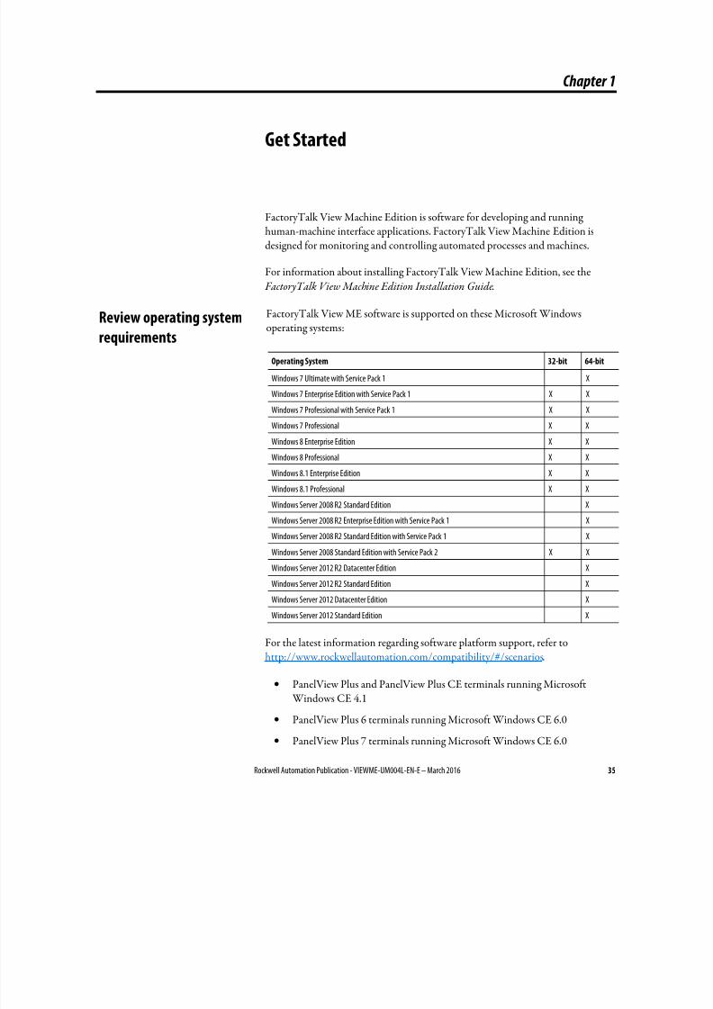
8/17/2019 FactoryTalk® View Machine Edition User's Guide
http://slidepdf.com/reader/full/factorytalk-view-machine-edition-users-guide 35/587
Rockwell Automation Publication - VIEWME-UM004L-EN-E – March 2016 35
Chapter 1
Get Started
FactoryTalk View Machine Edition is software for developing and runninghuman-machine interface applications. FactoryTalk View Machine Edition isdesigned for monitoring and controlling automated processes and machines.
For information about installing FactoryTalk View Machine Edition, see the FactoryTalk View Machine Edition Installation Guide.
FactoryTalk View ME software is supported on these Microsoft Windowsoperating systems:
Operating System 32-bit 64-bit
Windows 7 Ultimate with Service Pack 1 X
Windows 7 Enterprise Edition with Service Pack 1 X X
Windows 7 Professional with Service Pack 1 X X
Windows 7 Professional X X
Windows 8 Enterprise Edition X X
Windows 8 Professional X X
Windows 8.1 Enterprise Edition X X
Windows 8.1 Professional X X
Windows Server 2008 R2 Standard Edition X
Windows Server 2008 R2 Enterprise Edition with Service Pack 1 X
Windows Server 2008 R2 Standard Edition with Service Pack 1 X
Windows Server 2008 Standard Edition with Service Pack 2 X X
Windows Server 2012 R2 Datacenter Edition X
Windows Server 2012 R2 Standard Edition X
Windows Server 2012 Datacenter Edition X
Windows Server 2012 Standard Edition X
For the latest information regarding software platform support, refer tohttp://www.rockwellautomation.com/compatibility/#/scenarios.
• PanelView Plus and PanelView Plus CE terminals running Microsoft Windows CE 4.1
• PanelView Plus 6 terminals running Microsoft Windows CE 6.0
• PanelView Plus 7 terminals running Microsoft Windows CE 6.0
Review operating systemrequirements
8/17/2019 FactoryTalk® View Machine Edition User's Guide
http://slidepdf.com/reader/full/factorytalk-view-machine-edition-users-guide 36/587
Chapter 1 Get Started
36 Rockwell Automation Publication - VIEWME-UM004L-EN-E – March 2016
Tip: FactoryTalk View Studio is tested and supported on operating systems installedfrom original Microsoft media only. For operating systems installed by thecomputer vendor, please see Knowledgebase article 26842.
FactoryTalk View Machine Edition gives you all the tools you need to createeffective machine-level monitoring and control applications.
FactoryTalk View Machine Edition includes the following products:
• FactoryTalk View Studio is configuration software for developingmachine-level applications. This software runs on operating systems such asMicrosoft Windows 7, Windows 8, Windows 8.1, Windows Server 2008,and Windows Server 2012 operating systems.
• FactoryTalk View ME Station is a stand-alone runtime environment formachine-level applications. Use FactoryTalk View ME Station to run the
applications you develop in FactoryTalk View Studio.
• RSLinx Enterprise is a communication server built around FactoryTalktechnology to assist in developing and running your FactoryTalk View MEapplications.
You can run machine-level applications on the MobileView, PanelView Plus 7,PanelView Plus 6, PanelView Plus, and PanelView Plus CE terminals, as well as on personal computers.
Additional softwareThe FactoryTalk View installation DVD also includes two additional software products:
• RSLinx Classic is software that provides communications to a wide rangeof communication drivers. RSLinx Classic is an OPC-compliant data server.RSLinx Classic is available for personal computers only.
• Adobe Reader 11.0.08 is software for reading the online FactoryTalk View
Machine Edition User’s Guide. If desired, you can also use the software to
print the User’s Guide.
FactoryTalk View Studio tools
These tools are installed with FactoryTalk View Studio:
• Application Documenter is a software that provides detailed informationabout FactoryTalk applications.
The parts of FactoryTalk
View Machine Edition
The FactoryTalk View
Machine Edition tools
8/17/2019 FactoryTalk® View Machine Edition User's Guide
http://slidepdf.com/reader/full/factorytalk-view-machine-edition-users-guide 37/587
Get Started Chapter 1
Rockwell Automation Publication - VIEWME-UM004L-EN-E – March 2016 37
• Application Manager is a software for renaming, copying, deleting, backingup, and restoring applications.
• DeskLock is a software that prevents Microsoft Windows 7, Windows 8,
Windows 8.1, Windows Server 2008, and Windows Server 2012 operatingsystems users from exiting the FactoryTalk View application at run time.You can use this tool to set up a customized desktop and to prevent accessto Windows functions. You cannot use DeskLock if you are running yourapplication on a PanelView Plus 7, PanelView Plus 6, PanelView Plus,PanelView Plus Compact, or PanelView Plus CE terminal.
• FactoryTalk View File Viewer is a software for viewing the following typesof log files:
• SE datalog files
• ME datalog files
• ME alarm log files
• dBase files
• ME RecipePlus files
The log information can be shown in the form of list views or trend plots.
You can save the files as CSV or dBase files so that it is easier to do more
analysis.
• FTVIEWUSER Account Reset is a software for resetting theFTVIEWUSER account back to its default.
• Legacy Tag Database Conversion is a software for converting your legacytag database to a new format to work with Microsoft SQL database.
• ME Firmware Upgrade Wizard is a software for installing new firmwarereleases on PanelView Plus 7, PanelView Plus 6, PanelView Plus, PanelViewPlus Compact, and PanelView Plus CE terminals.
• ME Transfer Utility is a software for transferring a runtime application file(.mer) between the development computer and a MobileView, PanelViewPlus 7, PanelView Plus 6, PanelView Plus, PanelView Plus Compact, orPanelView Plus CE terminal, transferring Windows True Type font files
(.ttf and .ttc) to a PanelView Plus 7, PanelView Plus 6, PanelView Plus,PanelView Plus Compact, or PanelView Plus CE terminal, and comparing aruntime application on a MobileView, PanelView Plus 7, PanelView Plus 6,PanelView Plus, PanelView Plus Compact, or PanelView Plus CE terminal with a runtime application on a desktop computer.
• Tag Import and Export Wizard is a software for importing or exportingthe FactoryTalk View tag database.
• Rockwell Automation CSV Data Log Tamper Detection Utility is asoftware used to detect the integrity of a CSV data log file that contains
8/17/2019 FactoryTalk® View Machine Edition User's Guide
http://slidepdf.com/reader/full/factorytalk-view-machine-edition-users-guide 38/587
Chapter 1 Get Started
38 Rockwell Automation Publication - VIEWME-UM004L-EN-E – March 2016
tamper detection strings, generate a detection report, and save the report toa text file.
To start FactoryTalk View Studio tools
• From Windows Start menu, select Programs > Rockwell Software >
FactoryTalk View > Tools, and then select the tool.
You can also select tool from the Tools menu in FactoryTalk View Studio.
Diagnostics Viewer
Diagnostics Viewer allows you to view FactoryTalk Diagnostics messages using theFactoryTalk Diagnostics Viewer.
To start Diagnostics Viewer
• From Windows Start menu, select Programs > Rockwell Software >
FactoryTalk Tools > Diagnostics Viewer.
You can also select the tool from the Tools menu in FactoryTalk View
Studio.
FactoryTalk tools
FactoryTalk tools are installed when you install FactoryTalk Services Platform.
To start FactoryTalk tools
• From Windows Start menu, select Programs > Rockwell Software >
FactoryTalk Tools, and then select the tool.
FactoryTalk Activation Manager
FactoryTalk Activation Manager is automatically installed when you installFactoryTalk View.
To start FactoryTalk Activation Manager
• From Windows Start menu, select Programs > Rockwell Software >
FactoryTalk Activation > FactoryTalk Activation Manager .
8/17/2019 FactoryTalk® View Machine Edition User's Guide
http://slidepdf.com/reader/full/factorytalk-view-machine-edition-users-guide 39/587
Rockwell Automation Publication - VIEWME-UM004L-EN-E – March 2016 39
Chapter 2
Explore FactoryTalk View Studio
This chapter describes:
• Start and exit FactoryTalk View Studio
• Open sample applications
• Explore the FactoryTalk View Studio main window
•
Use the Explorer window• Work with editors
• Enter information in spreadsheets
• Print information in editors
For information about working with editors’ components, see Work withcomponents on page 298.
FactoryTalk View Studio is configuration software for developing machine-levelapplications. This software runs on Microsoft Windows 7, Windows 8, Windows
8.1, Windows Server 2008, and Windows Server 2012 operating systems.
Start FactoryTalk View Studio
To start FactoryTalk View Studio, from Windows Start menu, select Programs >
FactoryTalk View Studio.
FactoryTalk View comes with several sample applications. We suggest you openthe InstantFizz_ME sample application now to use while you try out theinstructions in the remainder of this chapter. See Open sample applications on
page 40.
Exit FactoryTalk View Studio
To exit FactoryTalk View Studio, from the File menu, select Exit.
If there are any unsaved changes in open editors, FactoryTalk View Studio asks you whether to save the changes before exiting the program.
Start and exit FactoryTalk
View Studio
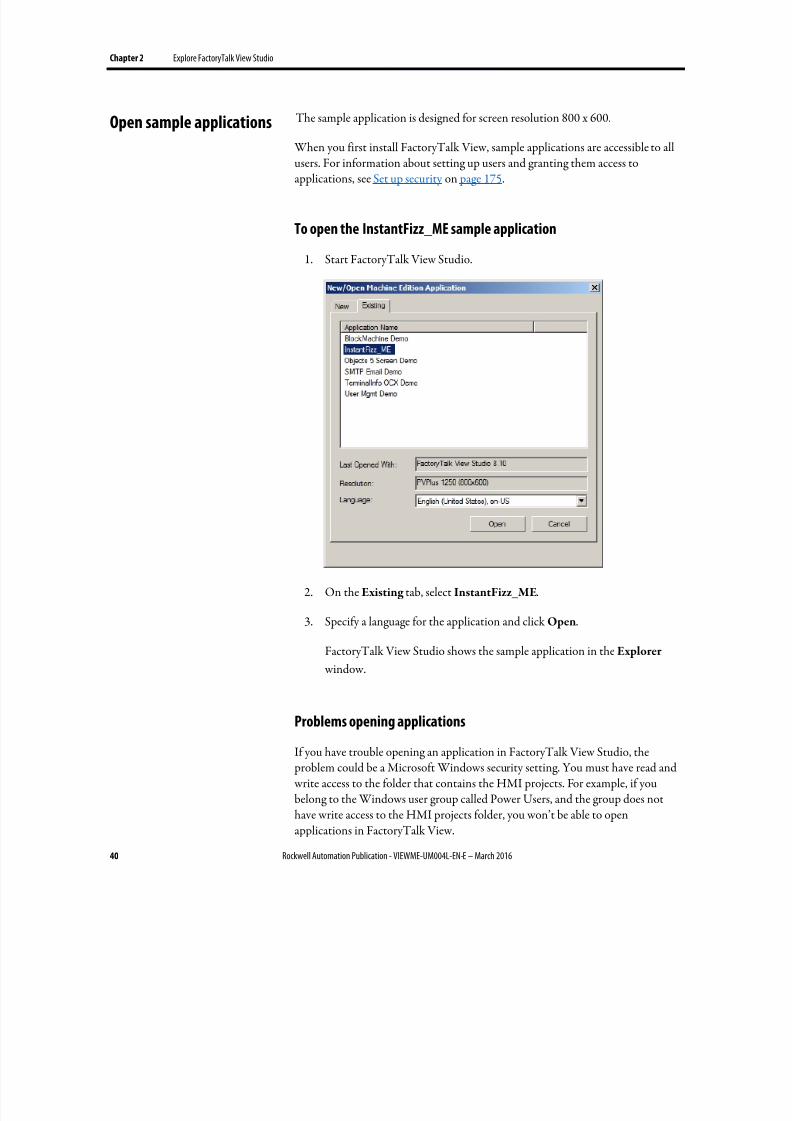
8/17/2019 FactoryTalk® View Machine Edition User's Guide
http://slidepdf.com/reader/full/factorytalk-view-machine-edition-users-guide 40/587
Chapter 2 Explore FactoryTalk View Studio
40 Rockwell Automation Publication - VIEWME-UM004L-EN-E – March 2016
The sample application is designed for screen resolution 800 x 600.
When you first install FactoryTalk View, sample applications are accessible to allusers. For information about setting up users and granting them access to
applications, see Set up security on page 175.
To open the InstantFizz_ME sample application
1. Start FactoryTalk View Studio.
2. On the Existing tab, select InstantFizz_ME.
3. Specify a language for the application and click Open.
FactoryTalk View Studio shows the sample application in the Explorer
window.
Problems opening applications
If you have trouble opening an application in FactoryTalk View Studio, the problem could be a Microsoft Windows security setting. You must have read and write access to the folder that contains the HMI projects. For example, if youbelong to the Windows user group called Power Users, and the group does nothave write access to the HMI projects folder, you won’t be able to openapplications in FactoryTalk View.
Open sample applications
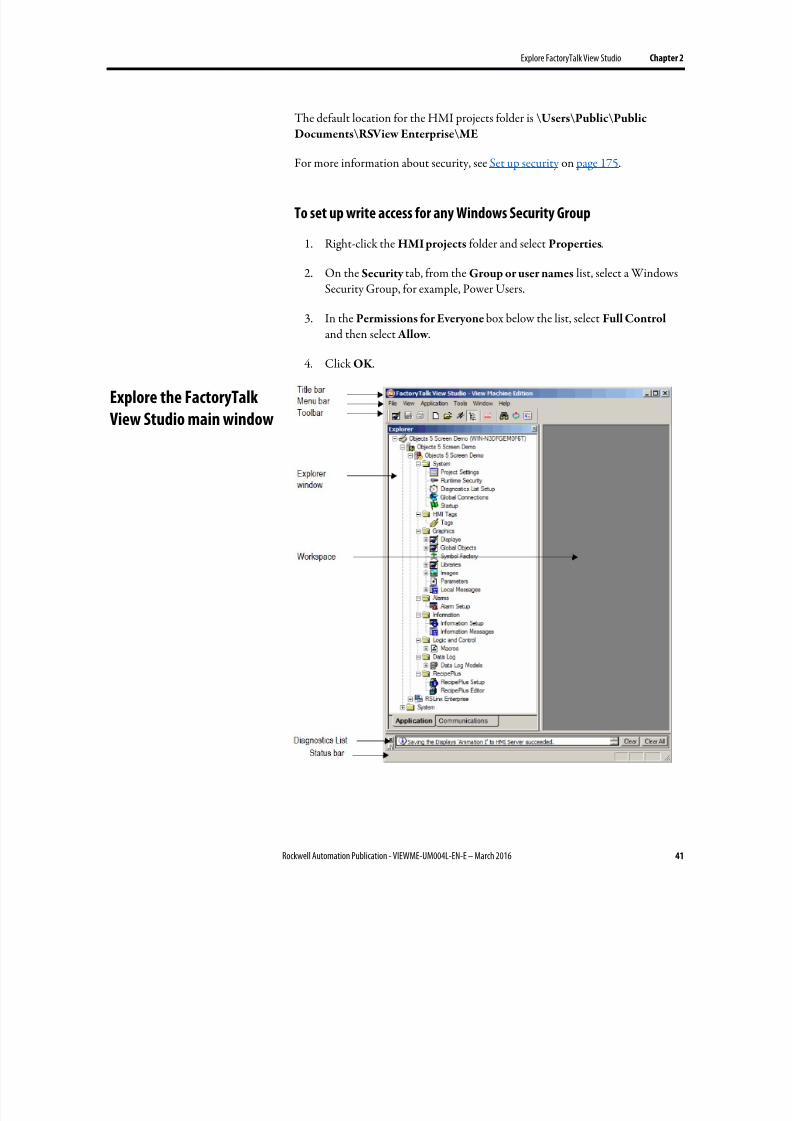
8/17/2019 FactoryTalk® View Machine Edition User's Guide
http://slidepdf.com/reader/full/factorytalk-view-machine-edition-users-guide 41/587
Explore FactoryTalk View Studio Chapter 2
Rockwell Automation Publication - VIEWME-UM004L-EN-E – March 2016 41
The default location for the HMI projects folder is \Users\Public\Public
Documents\RSView Enterprise\ME
For more information about security, see Set up security on page 175.
To set up write access for any Windows Security Group
1. Right-click the HMI projects folder and select Properties.
2.
On the Security tab, from the Group or user names list, select a WindowsSecurity Group, for example, Power Users.
3. In the Permissions for Everyone box below the list, select Full Control and then select Allow .
4. Click OK .
Explore the FactoryTalk
View Studio main window
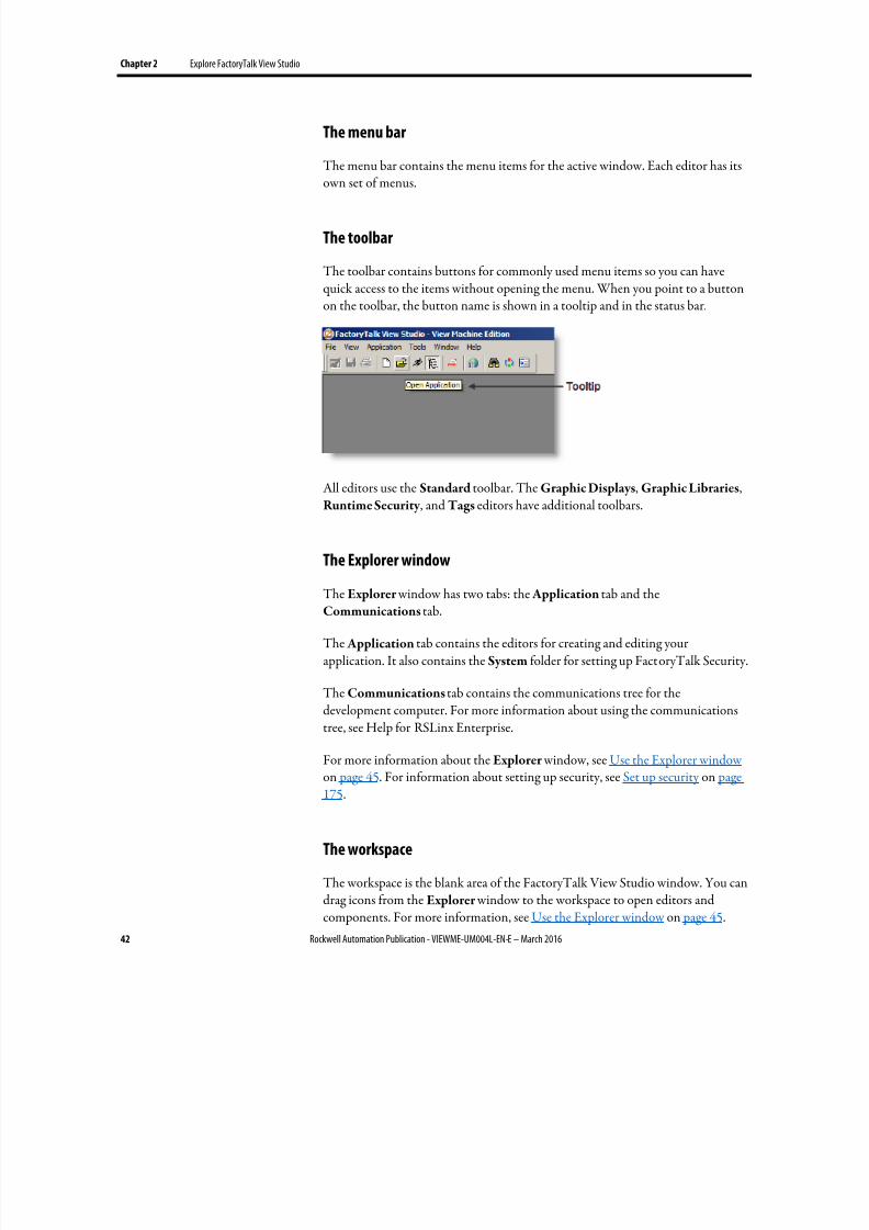
8/17/2019 FactoryTalk® View Machine Edition User's Guide
http://slidepdf.com/reader/full/factorytalk-view-machine-edition-users-guide 42/587
Chapter 2 Explore FactoryTalk View Studio
42 Rockwell Automation Publication - VIEWME-UM004L-EN-E – March 2016
The menu bar
The menu bar contains the menu items for the active window. Each editor has its
own set of menus.
The toolbar
The toolbar contains buttons for commonly used menu items so you can havequick access to the items without opening the menu. When you point to a buttonon the toolbar, the button name is shown in a tooltip and in the status bar.
All editors use the Standard toolbar. The Graphic Displays, Graphic Libraries,Runtime Security , and Tags editors have additional toolbars.
The Explorer window
The Explorer window has two tabs: the Application tab and theCommunications tab.
The Application tab contains the editors for creating and editing yourapplication. It also contains the System folder for setting up FactoryTalk Security.
The Communications tab contains the communications tree for thedevelopment computer. For more information about using the communicationstree, see Help for RSLinx Enterprise.
For more information about the Explorer window, see Use the Explorer window on page 45. For information about setting up security, see Set up security on page175.
The workspace
The workspace is the blank area of the FactoryTalk View Studio window. You candrag icons from the Explorer window to the workspace to open editors andcomponents. For more information, see Use the Explorer window on page 45.
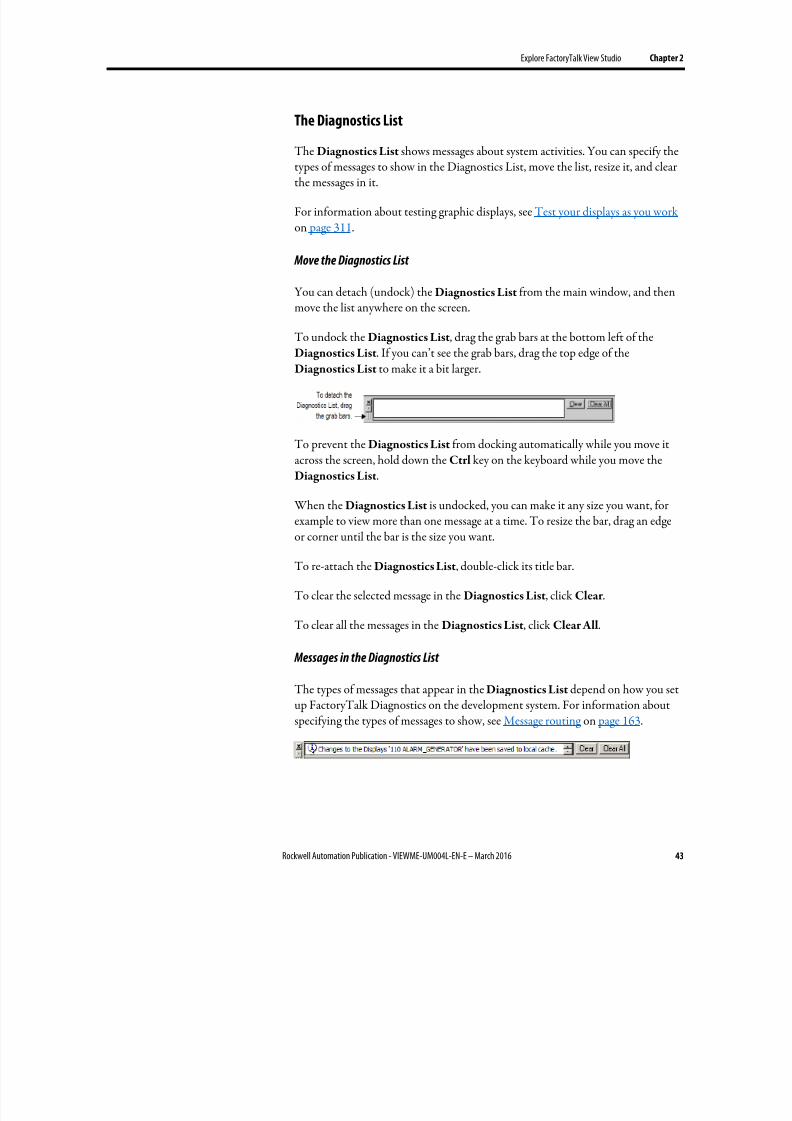
8/17/2019 FactoryTalk® View Machine Edition User's Guide
http://slidepdf.com/reader/full/factorytalk-view-machine-edition-users-guide 43/587
Explore FactoryTalk View Studio Chapter 2
Rockwell Automation Publication - VIEWME-UM004L-EN-E – March 2016 43
The Diagnostics List
The Diagnostics List shows messages about system activities. You can specify the
types of messages to show in the Diagnostics List, move the list, resize it, and clearthe messages in it.
For information about testing graphic displays, see Test your displays as you work on page 311.
Move the Diagnostics List
You can detach (undock) the Diagnostics List from the main window, and thenmove the list anywhere on the screen.
To undock the Diagnostics List, drag the grab bars at the bottom left of theDiagnostics List. If you can’t see the grab bars, drag the top edge of theDiagnostics List to make it a bit larger.
To prevent the Diagnostics List from docking automatically while you move itacross the screen, hold down the Ctrl key on the keyboard while you move theDiagnostics List.
When the Diagnostics List is undocked, you can make it any size you want, for
example to view more than one message at a time. To resize the bar, drag an edgeor corner until the bar is the size you want.
To re-attach the Diagnostics List, double-click its title bar.
To clear the selected message in the Diagnostics List, click Clear .
To clear all the messages in the Diagnostics List, click Clear All.
Messages in the Diagnostics List
The types of messages that appear in the Diagnostics List depend on how you setup FactoryTalk Diagnostics on the development system. For information aboutspecifying the types of messages to show, see Message routing on page 163.
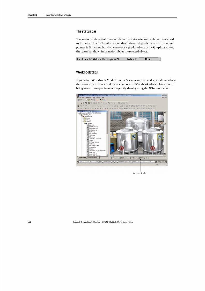
8/17/2019 FactoryTalk® View Machine Edition User's Guide
http://slidepdf.com/reader/full/factorytalk-view-machine-edition-users-guide 44/587
Chapter 2 Explore FactoryTalk View Studio
44 Rockwell Automation Publication - VIEWME-UM004L-EN-E – March 2016
The status bar
The status bar shows information about the active window or about the selected
tool or menu item. The information that is shown depends on where the mouse pointer is. For example, when you select a graphic object in the Graphics editor,the status bar shows information about the selected object.
Workbook tabs
If you select Workbook Mode from the View menu, the workspace shows tabs atthe bottom for each open editor or component. Workbook Mode allows you tobring forward an open item more quickly than by using the Window menu.
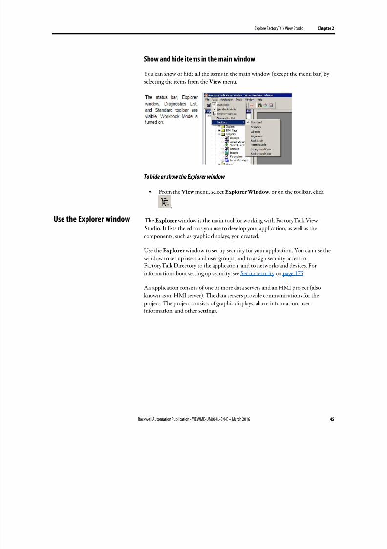
8/17/2019 FactoryTalk® View Machine Edition User's Guide
http://slidepdf.com/reader/full/factorytalk-view-machine-edition-users-guide 45/587
Explore FactoryTalk View Studio Chapter 2
Rockwell Automation Publication - VIEWME-UM004L-EN-E – March 2016 45
Show and hide items in the main window
You can show or hide all the items in the main window (except the menu bar) by
selecting the items from the View menu.
To hide or show the Explorer window
• From the View menu, select Explorer Window , or on the toolbar, click
.
The Explorer window is the main tool for working with FactoryTalk ViewStudio. It lists the editors you use to develop your application, as well as thecomponents, such as graphic displays, you created.
Use the Explorer window to set up security for your application. You can use the
window to set up users and user groups, and to assign security access toFactoryTalk Directory to the application, and to networks and devices. Forinformation about setting up security, see Set up security on page 175.
An application consists of one or more data servers and an HMI project (alsoknown as an HMI server). The data servers provide communications for the project. The project consists of graphic displays, alarm information, userinformation, and other settings.
Use the Explorer window
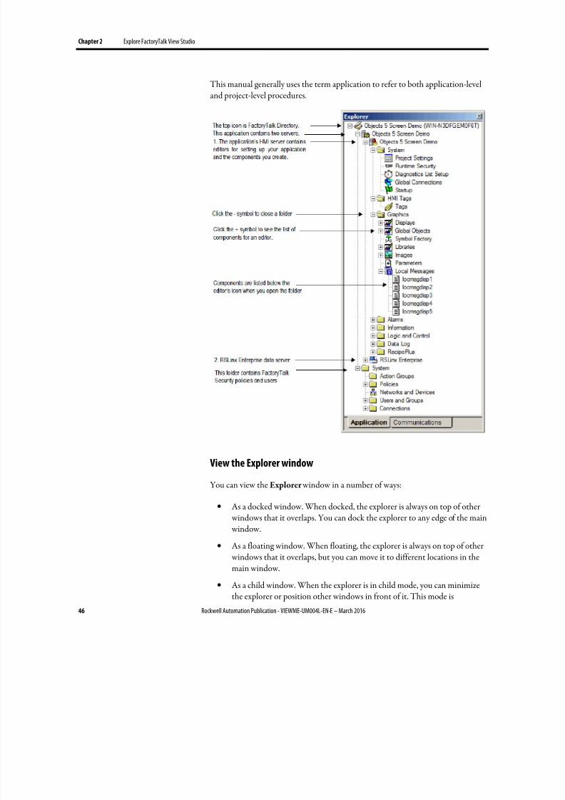
8/17/2019 FactoryTalk® View Machine Edition User's Guide
http://slidepdf.com/reader/full/factorytalk-view-machine-edition-users-guide 46/587
Chapter 2 Explore FactoryTalk View Studio
46 Rockwell Automation Publication - VIEWME-UM004L-EN-E – March 2016
This manual generally uses the term application to refer to both application-leveland project-level procedures.
View the Explorer window
You can view the Explorer window in a number of ways:
• As a docked window. When docked, the explorer is always on top of other windows that it overlaps. You can dock the explorer to any edge of the main window.
• As a floating window. When floating, the explorer is always on top of other windows that it overlaps, but you can move it to different locations in themain window.
• As a child window. When the explorer is in child mode, you can minimizethe explorer or position other windows in front of it. This mode is
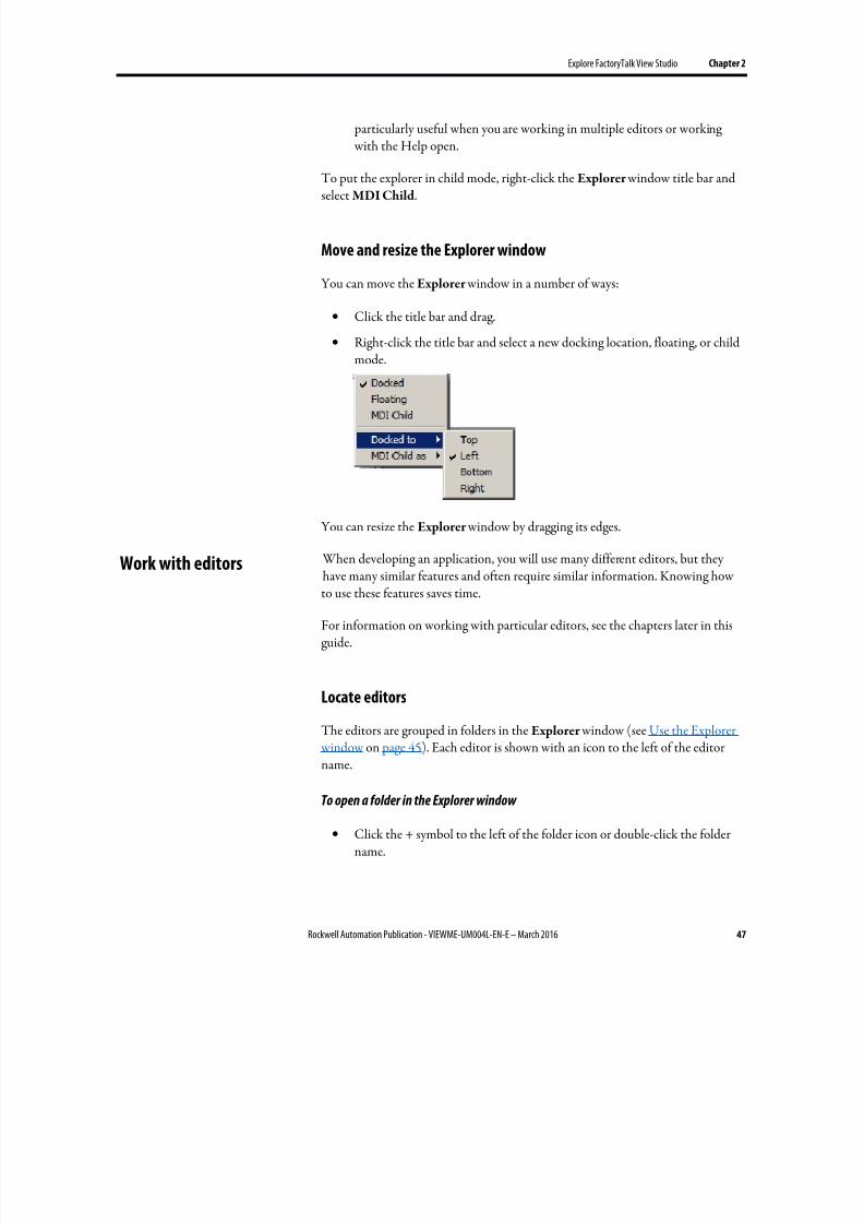
8/17/2019 FactoryTalk® View Machine Edition User's Guide
http://slidepdf.com/reader/full/factorytalk-view-machine-edition-users-guide 47/587
Explore FactoryTalk View Studio Chapter 2
Rockwell Automation Publication - VIEWME-UM004L-EN-E – March 2016 47
particularly useful when you are working in multiple editors or working with the Help open.
To put the explorer in child mode, right-click the Explorer window title bar and
select MDI Child.
Move and resize the Explorer window
You can move the Explorer window in a number of ways:
• Click the title bar and drag.
• Right-click the title bar and select a new docking location, floating, or childmode.
You can resize the Explorer window by dragging its edges.
When developing an application, you will use many different editors, but theyhave many similar features and often require similar information. Knowing howto use these features saves time.
For information on working with particular editors, see the chapters later in thisguide.
Locate editors
The editors are grouped in folders in the Explorer window (see Use the Explorer window on page 45). Each editor is shown with an icon to the left of the editor
name.
To open a folder in the Explorer window
• Click the + symbol to the left of the folder icon or double-click the foldername.
Work with editors
8/17/2019 FactoryTalk® View Machine Edition User's Guide
http://slidepdf.com/reader/full/factorytalk-view-machine-edition-users-guide 48/587
Chapter 2 Explore FactoryTalk View Studio
48 Rockwell Automation Publication - VIEWME-UM004L-EN-E – March 2016
View an editor's components
With some editors you enter information in a single window or a tabbed dialog
box. Other editors allow you to create multiple components, such as graphicdisplays or message files. Each component is stored in a separate file, with its ownname.
You can create components in these editors:
• Graphics (components include graphic displays, global object displays, andgraphic libraries, each in their own folder)
• Alarms
• Parameters
•
Local Messages • Information Messages
• Data Log Models
• Macros
• RecipePlus
The Explorer window lists the components you create under the icon for theeditor you used to create the component.
Use the Images editor to copy bitmap images into your application (but not tocreate new images). Each image you copy is listed as a component under the editor.
To view a list of components for an editor
• Click the + symbol to the left of the editor icon, or double-click the editorname.
For information about working with components, see Work with components on page 298.
Open editors
Use the editors in FactoryTalk View Studio to create or modify applicationcomponents. Editors are represented by icons in the Explorer window or by itemsin menus.
To open an editor
Use one of these methods:
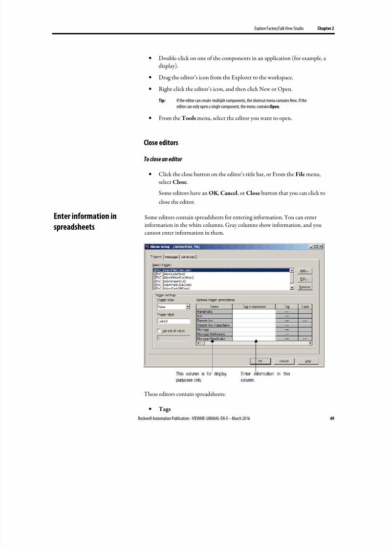
8/17/2019 FactoryTalk® View Machine Edition User's Guide
http://slidepdf.com/reader/full/factorytalk-view-machine-edition-users-guide 49/587
Explore FactoryTalk View Studio Chapter 2
Rockwell Automation Publication - VIEWME-UM004L-EN-E – March 2016 49
• Double-click on one of the components in an application (for example, adisplay).
• Drag the editor’s icon from the Explorer to the workspace.
•
Right-click the editor’s icon, and then click New or Open.
Tip: If the editor can create multiple components, the shortcut menu contains New. If theeditor can only open a single component, the menu contains Open.
• From the Tools menu, select the editor you want to open.
Close editors
To close an editor
•
Click the close button on the editor’s title bar, or From the File menu,select Close.
Some editors have an OK , Cancel, or Close button that you can click to
close the editor.
Some editors contain spreadsheets for entering information. You can enterinformation in the white columns. Gray columns show information, and youcannot enter information in them.
These editors contain spreadsheets:
• Tags
Enter information in
spreadsheets
8/17/2019 FactoryTalk® View Machine Edition User's Guide
http://slidepdf.com/reader/full/factorytalk-view-machine-edition-users-guide 50/587
Chapter 2 Explore FactoryTalk View Studio
50 Rockwell Automation Publication - VIEWME-UM004L-EN-E – March 2016
• Runtime Security (formerly User Accounts)
• Global Connections
• Local Messages
• Alarm Setup
• Information Setup
• Information Messages
• Macros
• RecipePlus Editor
In the Graphics editor, many of the Properties dialog boxes for setting up graphicobjects contain spreadsheets for assigning tags or expressions to the objects.
To enter information in a cell in a spreadsheet
• Click the cell, and then type the information. If the cell already containstext, the new information is added after the current text.
In the Property Panel, double-click the cell and then type the information.
If the cell already contains text, double-clicking highlights the text and
typing replaces the highlighted text.
To move to the next cell in the row
• Press Tab or Enter .
The method to use depends on which editor you are working in.
To move to the first cell in the next row
• Press Enter or Down Arrow .
The method to use depends on which editor you are working in.
To delete a cell’s contents
• Click the cell, and then press Delete or Backspace. Pressing Backspaceremoves the characters one by one.
The method to use depends on which editor you are working in.
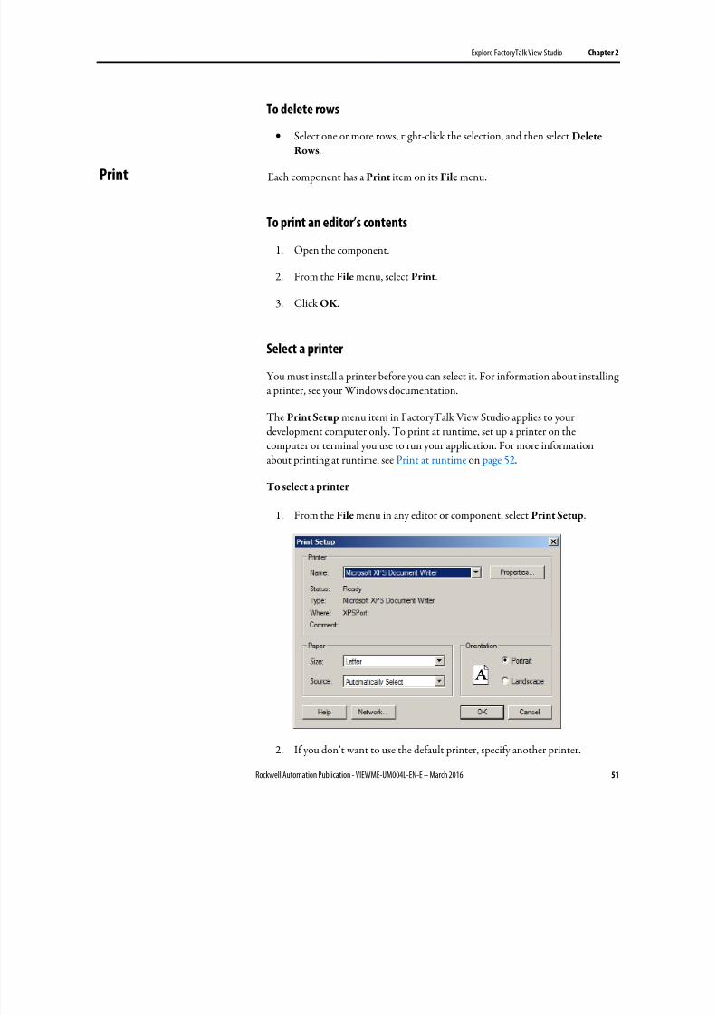
8/17/2019 FactoryTalk® View Machine Edition User's Guide
http://slidepdf.com/reader/full/factorytalk-view-machine-edition-users-guide 51/587
Explore FactoryTalk View Studio Chapter 2
Rockwell Automation Publication - VIEWME-UM004L-EN-E – March 2016 51
To delete rows
• Select one or more rows, right-click the selection, and then select Delete
Rows.
Each component has a Print item on its File menu.
To print an editor’s contents
1. Open the component.
2. From the File menu, select Print.
3. Click OK .
Select a printer
You must install a printer before you can select it. For information about installinga printer, see your Windows documentation.
The Print Setup menu item in FactoryTalk View Studio applies to yourdevelopment computer only. To print at runtime, set up a printer on thecomputer or terminal you use to run your application. For more informationabout printing at runtime, see Print at runtime on page 52.
To select a printer
1. From the File menu in any editor or component, select Print Setup.
2. If you don’t want to use the default printer, specify another printer.
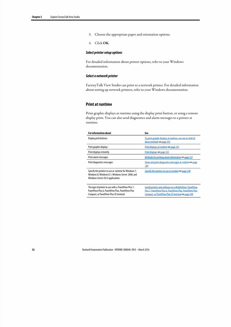
8/17/2019 FactoryTalk® View Machine Edition User's Guide
http://slidepdf.com/reader/full/factorytalk-view-machine-edition-users-guide 52/587
Chapter 2 Explore FactoryTalk View Studio
52 Rockwell Automation Publication - VIEWME-UM004L-EN-E – March 2016
3. Choose the appropriate paper and orientation options.
4. Click OK .
Select printer setup options
For detailed information about printer options, refer to your Windowsdocumentation.
Select a network printer
FactoryTalk View Studio can print to a network printer. For detailed informationabout setting up network printers, refer to your Windows documentation.
Print at runtime
Print graphic displays at runtime using the display print button, or using a remotedisplay print. You can also send diagnostics and alarm messages to a printer atruntime.
For information about See
Display print buttons To print graphic displays at runtime, use one or both ofthese methods on page 333
Print graphic displays Print displays at runtime on page 332
Print displays remotely Print displays on page 332 Print alarm messages Methods for printing alarm information on page 127
Print diagnostics messages Show and print diagnostics messages at runtime on page169
Specify the printers to use at runtime for Windows 7,Windows 8, Windows 8.1, Windows Server 2008, andWindows Server 2012 applications
Specify the printers to use at runtime on page 238
The type of printer to use with a PanelView Plus 7,PanelView Plus 6, PanelView Plus, PanelView PlusCompact, or PanelView Plus CE terminal
Install printers and software on a MobileView, PanelViewPlus 7, PanelView Plus 6, PanelView Plus, PanelView PlusCompact, or PanelView Plus CE terminal on page 248
8/17/2019 FactoryTalk® View Machine Edition User's Guide
http://slidepdf.com/reader/full/factorytalk-view-machine-edition-users-guide 53/587
Rockwell Automation Publication - VIEWME-UM004L-EN-E – March 2016 53
Chapter 3
Plan applications
A well-designed application requires planning. To help you plan, this chapterdescribes:
• Understand the machines and processes you’re automating
• Collect data
• Design an HMI tag database
• Plan graphic displays and navigating between them
• Plan languages
• Plan alarms
• Provide information for the operator
• Plan trends
• Plan recipes
• Design a secure system
FactoryTalk View comes with several sample applications that can give youguidance when planning your application. For instructions on opening the sampleapplications, see Open sample applications on page 40.
Gather information from a variety of sources so you have a complete and detailedunderstanding of the machines and processes you’re automating.
To gather information:
• Talk to machine operators and other experts who are going to use thesystem. Find out what information they need to optimize machine
operations and processes.
• Talk to management and management information systems staff to find out what information they need to support planning decisions.
• Break up each section of the process into its constituent parts.
• Determine what type of communications you’ll be using — which networktypes, data servers, and devices.
• Determine which process variables you need to have access to and identifytheir locations in the programmable controllers.
Understand the process
8/17/2019 FactoryTalk® View Machine Edition User's Guide
http://slidepdf.com/reader/full/factorytalk-view-machine-edition-users-guide 54/587
Chapter 3 Plan applications
54 Rockwell Automation Publication - VIEWME-UM004L-EN-E – March 2016
When planning data collection, design your system so only essential data iscollected. Limiting data collection is important because collection activitiesrequire substantial processing power and generate a lot of traffic on the network.
Keep data collection requirements in mind when designing the layout of the programmable controller data tables and the HMI tag database. Ideally, tagaddresses reference contiguous blocks of programmable controller data tables toreduce highway traffic and optimize system response. If you’re going to use datafrom an OPC server, read the server documentation to find out how to optimizetraffic.
Take the time to plan your HMI tag database. A good design helps reduce thetime required for maintenance and can improve programmablecontroller-to-FactoryTalk View response time.
For information about creating HMI tags, see Use HMI tags on page 99.
Tip: If you are going to use direct referencing for all your tags, you don’t need to create HMItags in FactoryTalk View.
Data Server tags usually update faster than HMI tags. To obtain the best systemperformance for your application, use Data Server tags where possible.
For information about creating Data Servers to data server tags, see Work withtags on page 87.
Collect information
Before you begin creating the tag database, collect:
• Flowcharts of your processes (or process and instrument diagrams).
• A list of programmable controller data table or register addresses yourapplication will have access to.
• Machinery systems documentation.
• Alarm requirements (for more information, see Plan alarms on page 58).
Organize tags
Before creating tags:
• Develop naming conventions for tags, choosing names that are familiar andlogical to everyone. This makes troubleshooting easier.
• Group related tags.
Collect data
Design an HMI tag database
8/17/2019 FactoryTalk® View Machine Edition User's Guide
http://slidepdf.com/reader/full/factorytalk-view-machine-edition-users-guide 55/587
Plan applications Chapter 3
Rockwell Automation Publication - VIEWME-UM004L-EN-E – March 2016 55
Group tags in the way that makes the most sense for your application. For
example, group all similar devices or group related areas of the plant floor.
When creating tags, place related tags into folders. For greater organization,
nest folders.
When planning displays, determine the best way for users to navigate through your displays and develop a template to establish a common look and feel for yourdisplays.
Also consider factors about the runtime terminal that affect how the application isshown and used, such as:
• Screen size
•
The maximum number of displays supported at runtime• If the applications runs on a personal computer, the maximum number of
displays is based on the type of activation used
• If the application runs on a MobileView, PanelView Plus 7, PanelView Plus6, PanelView Plus, PanelView Plus Compact, or PanelView Plus CEterminal, the maximum number of displays is based on the amount ofmemory used by the application. Applications running on the terminal cancontain as many displays as can fit in the memory of the terminal.
• PanelView Plus 7 Standard applications and Compact Machine Editionapplications have a limit of 25 displays.
•
Whether the operator will be using a keyboard, touch screen, mouse, orcombination of navigation and data entry methods.
For information about creating graphic displays, see Use graphic displays on page303.
Develop a hierarchy of displays
A hierarchy of displays is a series of graphic displays that provide progressivelymore detail as users move through them. Design your display hierarchy to meet theneeds of the various users, including managers, supervisors, and operators.
Well-organized graphic displays present information clearly and consistently andguide users through the system. Before designing individual graphic displays, planan overall display hierarchy and plan how users will navigate through thehierarchy.
For information about navigation methods and developing a hierarchy of displays,see Set up global connections on page 111.
Plan graphic displays
8/17/2019 FactoryTalk® View Machine Edition User's Guide
http://slidepdf.com/reader/full/factorytalk-view-machine-edition-users-guide 56/587
Chapter 3 Plan applications
56 Rockwell Automation Publication - VIEWME-UM004L-EN-E – March 2016
Create a template to ensure consistency
It is possible to keep a consistent appearance among all the displays in an
application by presenting the same pieces of information in the same place on eachgraphic display. To ensure uniformity, develop a display with common elementsthat acts as a template. Each time you develop a new display, start with a duplicateof the template.
For example, the template could contain:
• Your company logo
• A title
• The date and time
•
Navigational buttons
Use global object displays to create template objects. You can copy the objects into your graphic displays, and update all the objects at once by updating the originalobject in the global object display. For information about creating global objectdisplays, see Create global object displays and base objects on page 470.
Design displays
When designing displays, applying good visual design principles helps users and
increases their efficiency.
Remember these important design principles:
Consistency
• Be consistent with your use of symbols and color.
• Be consistent with button labels and button placement.
When you design several displays, place the same kinds of buttons on the
same positions. For example, if you have a Start button in a certain position
in one display, don’t put a Stop button in the same position in the nextdisplay.
Clarity
• Use symbols that are easily recognizable. For example, use the conventionalISA symbols for tanks and valves.
• Don’t overload the screen with information.
8/17/2019 FactoryTalk® View Machine Edition User's Guide
http://slidepdf.com/reader/full/factorytalk-view-machine-edition-users-guide 57/587
Plan applications Chapter 3
Rockwell Automation Publication - VIEWME-UM004L-EN-E – March 2016 57
• Use standard, clear terminology, and avoid abbreviations or acronyms thatthe user might not understand.
• Use colors with recognizable meanings. For example, in North America the
colors red and green usually mean stop and start. Keep color meaningsconsistent by assigning red only to Stop buttons, and green only to Startbuttons.
Some people are color blind to red and green so don’t rely on color alone to
establish meaning.
• Use high contrast color combinations, such as yellow on blue.
Display types
• On Top display type is used to position the display in front of any other
display that is already open at runtime.
• Replace display type is used to have the display close any open displays onthe screen at runtime. Replace displays do not close displays of the type OnTop that have the Cannot Be Replaced option selected. Only one Replacedisplay can be open at a time.
Usability
• If you’re designing for a touch screen, don’t place important buttons wherethey’ll be blocked by an On Top display. The user can’t press a coveredbutton. Also, ensure the button is large enough for users to touch easily.
• Ensure there is always a clear way to move between displays.
• Keep the intended user in mind and design displays so they are easy tounderstand and use. Ask the users to test the displays.
Before setting up languages, plan:
• Which languages you need to use
• Which Windows fonts support these languages
• For applications running on a personal computer or a MobileView
terminal, which Windows fonts support these languages
• For applications running on a PanelView Plus 7, PanelView Plus 6,PanelView Plus, PanelView Plus Compact, or PanelView Plus CEterminal, which languages the fonts resident on the terminal support
• How different languages will affect design elements in your graphic displays,such as object size and message length
Plan languages
8/17/2019 FactoryTalk® View Machine Edition User's Guide
http://slidepdf.com/reader/full/factorytalk-view-machine-edition-users-guide 58/587
Chapter 3 Plan applications
58 Rockwell Automation Publication - VIEWME-UM004L-EN-E – March 2016
• Whether operators need to switch languages at runtime, and if so, under what conditions. This will help you determine where to locate Language
Switch buttons in your application
•
How to show operators which button to press to switch to their languages.For example, by using a text label in French or a French flag, to alert aFrench operator
For information about setting up language switching, see Set up languageswitching on page 199.
Before setting up alarms, plan:
• What conditions will trigger alarms
• How operators will be notified of alarms
• What information you want alarm messages to contain
• How operators will respond to alarms
• The maximum number of alarm messages supported at runtime
For information about setting up alarms, see Set up alarms on page 119.
In addition to notifying the operator of alarm conditions, you can provideinformation and instructions about plant processes, and inform the operatorabout system activities.
Before setting up information notification, plan:
• What system activity the operator needs to be informed about
• What conditions will trigger information messages
• What information you want the messages to contain
Local and information messages
Use local messages to give the operator information in a specific graphic display
while the display is open. Use information messages to give the operatorinformation no matter which display is open.
For information about setting up local messages, see Use local messages on page328. For information about setting up information messages, see Use informationmessages on page 485.
Plan alarms
Provide information for the
operator
8/17/2019 FactoryTalk® View Machine Edition User's Guide
http://slidepdf.com/reader/full/factorytalk-view-machine-edition-users-guide 59/587
Plan applications Chapter 3
Rockwell Automation Publication - VIEWME-UM004L-EN-E – March 2016 59
Diagnostics messages
Set up diagnostics messages to notify the operator of system activity such as tag
reads and writes, running macros, communication problems, or problems openingdisplays.
For information about setting up diagnostics messages, see Set up FactoryTalkDiagnostics on page 161.
When planning trends, consider how they will be used. For example, will thetrend be used to:
• Analyze process trends?
• Monitor production efficiency?
•
Archive process variables to ensure compliance with governmentregulations?
Based on such considerations, you can determine:
• Which tags need to be plotted on the same trend.
• Which tags need to be logged by using a data log model.
For information about setting up data logging, see Set up data logging on page 479.
For information about creating trend graphic objects, see Set up trends on page
493.
When planning recipes, consider how they will be used. For example, will recipesbe used to:
• Compare tag values to pre-set data values?
• Upload tag values to existing or new data sets?
• Download values from data sets to tags?
• Archive tag values to ensure compliance with government regulations?
Based on such considerations, you can determine:
• Which tag sets and data sets to pair together in a recipe file.
• Which RecipePlus button actions to use with the RecipePlus selector andRecipePlus table.
For information about using recipes and creating RecipePlus graphic objects, seeSet up ReciplePlus on page 505.
Plan trends
Plan recipes

8/17/2019 FactoryTalk® View Machine Edition User's Guide
http://slidepdf.com/reader/full/factorytalk-view-machine-edition-users-guide 60/587
Chapter 3 Plan applications
60 Rockwell Automation Publication - VIEWME-UM004L-EN-E – March 2016
When deciding on your security requirements, consider whether to:
• Restrict access to every graphic display to prevent accidental changes.
•
Restrict access to certain graphic displays.
• Have everyone log on.
• Use passwords, and if so, whether to have a minimum length, and whetherto require that the passwords are changed periodically.
• Allow only authorized users to shut down the application.
• Use the DeskLock tool on Windows platforms to prevent users fromswitching to another application at runtime (for applications that will runon personal computers). You can use this tool to set up a customizeddesktop and to prevent access to Windows functions.
Based on these considerations, you can set up security for individual users orgroups of users. For example, you might want to set up groups of users such as amanager group and an operator group.
For more information about setting up security, see Set up security on page 175.
Design a secure system
8/17/2019 FactoryTalk® View Machine Edition User's Guide
http://slidepdf.com/reader/full/factorytalk-view-machine-edition-users-guide 61/587
Rockwell Automation Publication - VIEWME-UM004L-EN-E – March 2016 61
Chapter 4
Work with applications
This chapter describes:
• Application files
• Create, import, open, and close applications
• Rename, copy, delete, back up, and restore applications
•
Specify project settings• View application properties
• View HMI server properties
An application is the software application you create in FactoryTalk View Studioto monitor and control your plant processes. An application consists of one ormore data servers and an HMI project (also known as an HMI server). The dataservers provide communications for the project. The project or HMI serverconsists of graphic displays, alarm information, user information, and othersettings.
For information about viewing the application properties, see View application properties on page 79. For information about viewing the HMI server properties,see View HMI server properties on page 80.
Application versus project
This manual generally uses the term application to refer to both application-leveland project-level procedures. There is an exception on using the Project Settings editor. See About project settings on page 73. In that section, the term project isused.
When you create an application, FactoryTalk View creates folders and files in various locations on the development computer. Some of the folders are emptyuntil you start setting up your application. When you finish developing theapplication, FactoryTalk View uses the information in the various folders and filesto create the runtime application.
What is an application?
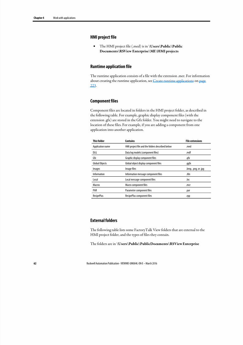
8/17/2019 FactoryTalk® View Machine Edition User's Guide
http://slidepdf.com/reader/full/factorytalk-view-machine-edition-users-guide 62/587
Chapter 4 Work with applications
62 Rockwell Automation Publication - VIEWME-UM004L-EN-E – March 2016
HMI project file
• The HMI project file (.med) is in \Users\Public\Public
Documents\RSView Enterprise\ME\HMI projects
Runtime application file
The runtime application consists of a file with the extension .mer. For informationabout creating the runtime application, see Create runtime applications on page223.
Component files
Component files are located in folders in the HMI project folder, as described inthe following table. For example, graphic display component files (with theextension .gfx) are stored in the Gfx folder. You might need to navigate to thelocation of these files. For example, if you are adding a component from oneapplication into another application.
This folder Contains File extensions
Application name HMI project file and the folders described below .med
DLG Data log models (component files) .mdf
Gfx Graphic display component files .gfx
Global Objects Global object display component files .ggfx
Images Image files .bmp, .png, or .jpg
Information Information message component files .ifm
Local Local message component files .loc
Macros Macro component files .mcr
PAR Parameter component files .par
RecipePlus RecipePlus component files .rpp
External folders
The following table lists some FactoryTalk View folders that are external to theHMI project folder, and the types of files they contain.
The folders are in \Users\Public\PublicDocuments\RSView Enterprise
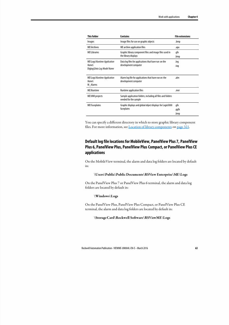
8/17/2019 FactoryTalk® View Machine Edition User's Guide
http://slidepdf.com/reader/full/factorytalk-view-machine-edition-users-guide 63/587
Work with applications Chapter 4
Rockwell Automation Publication - VIEWME-UM004L-EN-E – March 2016 63
This folder Contains File extensions
Images Image files for use on graphic objects .bmp
ME\Archives ME archive application files .apa
ME\Libraries Graphic library component files and image files used inthe library displays
.gfx
.bmp
ME\Logs\Runtime Application
Name\Dlglog\Data Log Model Name
Data log files for applications that have run on thedevelopment computer
.log
.tag
ME\Logs\Runtime Application
Name\M_Alarms
Alarm log file for applications that have run on thedevelopment computer
.alm
ME\Runtime Runtime application files .mer
ME\HMI projects Sample application folders, including all files and folders
needed for the sampleME\Faceplates Graphic displays and global object displays for Logix5000
faceplates.gfx
.ggfx
.bmp
You can specify a different directory in which to store graphic library componentfiles. For more information, see Location of library components on page 321.
Default log file locations for MobileView, PanelView Plus 7, PanelView
Plus 6, PanelView Plus, PanelView Plus Compact, or PanelView Plus CE
applications
On the MobileView terminal, the alarm and data log folders are located by defaultin:
\Users\Public\Public Documents\RSView Enterprise\ME\Logs
On the PanelView Plus 7 or PanelView Plus 6 terminal, the alarm and data logfolders are located by default in:
\Windows\Logs
On the PanelView Plus, PanelView Plus Compact, or PanelView Plus CEterminal, the alarm and data log folders are located by default in:
\Storage Card\Rockwell Software\RSViewME\Logs
8/17/2019 FactoryTalk® View Machine Edition User's Guide
http://slidepdf.com/reader/full/factorytalk-view-machine-edition-users-guide 64/587
Chapter 4 Work with applications
64 Rockwell Automation Publication - VIEWME-UM004L-EN-E – March 2016
Data log file locations
You can also store data log files in a different location on the runtime computer,on a networked computer, or on a PC card. For more information, see Set up datalogging on page 479.
Name files
File names, including the path, can be up to 200 characters long (file names cancontain spaces). For example, the following path and file name contains 119characters:
C:\Documents and Settings\All Users\Documents\RSView
Enterprise\ME\HMI projects\Malthouse Clgx640x480\Gfx\Steeping.gfx
Create an application
You can create a FactoryTalk View Machine Edition application when you startFactoryTalk View Studio or when FactoryTalk View Studio is open.
To create an application
1.
If FactoryTalk View Studio is not started, start FactoryTalk View Studio.
Create, import, open, and
close applications
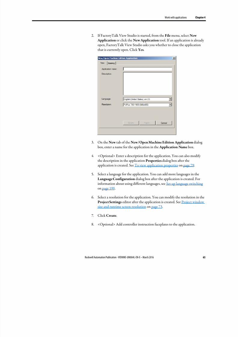
8/17/2019 FactoryTalk® View Machine Edition User's Guide
http://slidepdf.com/reader/full/factorytalk-view-machine-edition-users-guide 65/587
Work with applications Chapter 4
Rockwell Automation Publication - VIEWME-UM004L-EN-E – March 2016 65
2. If FactoryTalk View Studio is started, from the File menu, select New
Application or click the New Application tool. If an application is alreadyopen, FactoryTalk View Studio asks you whether to close the applicationthat is currently open. Click Yes.
3. On the New tab of the New/Open Machine Edition Application dialogbox, enter a name for the application in the Application Name box.
4.
<Optional> Enter a description for the application. You can also modifythe description in the application Properties dialog box after theapplication is created. See To view application properties on page 79.
5.
Select a language for the application. You can add more languages in theLanguage Configuration dialog box after the application is created. Forinformation about using different languages, see Set up language switching on page 199.
6. Select a resolution for the application. You can modify the resolution in theProject Settings editor after the application is created. See Project windowsize and runtime screen resolution on page 73.
7. Click Create.
8. <Optional> Add controller instruction faceplates to the application.
8/17/2019 FactoryTalk® View Machine Edition User's Guide
http://slidepdf.com/reader/full/factorytalk-view-machine-edition-users-guide 66/587
Chapter 4 Work with applications
66 Rockwell Automation Publication - VIEWME-UM004L-EN-E – March 2016
Tip: Adding faceplate displays to an application affects the license count. Each addedfaceplate display (.gfx) counts as one display for acti vation purposes. Thecorresponding global object display (.ggfx) does not add to the total license count.
FactoryTalk View Studio creates the application’s folders and files and then showsthe new application in the Explorer window. The system automatically creates adisplay called MAIN and sets the initial graphic to Main.
The application files are stored in:
\Users\Public\Public Documents\RSView Enterprise\ME\HMI projects\<ApplicationName>
The application file is given the extension .med.
Import an application
You can import the following application files to FactoryTalk View Studio andconvert them to current version FactoryTalk View Machine Edition applicationfiles using Machine Edition Import Wizard:
• PanelBuilder application (.pba or .pva)
• PanelBuilder32 application (.pba or .pva)
•
PanelBuilder 1400e application (.pvc)
• RSView Machine Edition application (.med)
• FactoryTalk View Machine Edition application (.med)
When importing an application:
• If the application contains any direct driver nodes, the Import Wizard willcreate a RSLinx topic for each direct driver node it finds. All topics are thenconverted to device shortcuts to run with RSLinx Enterprise. You musthave RSLinx Classic and RSLinx Enterprise installed to complete the
conversion.• If the application includes alarm block tags, the conversion process creates
direct references for each of the block tags imported. The direct reference isbased on the original block tag name and address, with the modifier "L"appended. The "L" modifier is followed by the number of elements to beread. The number is arrived at by dividing the number of bits that is definedfor the block tag by the number of bits in each address element (assumed tobe a 16-bit word). For example, if the original block tag had 47 bits defined,using the address N7:0, it would be converted to a direct reference asN7:0,L3.
8/17/2019 FactoryTalk® View Machine Edition User's Guide
http://slidepdf.com/reader/full/factorytalk-view-machine-edition-users-guide 67/587
Work with applications Chapter 4
Rockwell Automation Publication - VIEWME-UM004L-EN-E – March 2016 67
• If the application files are created with an earlier version FactoryTalk View,FactoryTalk View will create a copy of the application for the current version and will not alter the earlier version.
•
PanelView Plus 7 Standard application will be converted to PanelView Plus7 Performance or custom size application, and the application limits will beremoved. If you want a PanelView Plus 7 Standard application, specify the project window size in the Project Settings dialog box after the applicationis imported.
• Compact Machine Edition application will be converted to regularnon-compact application, and the application limits will be removed. If you want a Compact Machine Edition application, specify the project windowsize in the Project Settings dialog box after the application is imported.
• The Import Wizard converts PanelBuilder objects to the most similar
Machine Edition objects. When conversion is not possible, an error messageis shown.
• A PanelBuilder application will be converted to a Machine Editionapplication that does not contain a border or a title bar.
You can use the current version application files to create previous versionruntime files in FactoryTalk View Studio. For more information, see Open andedit applications from earlier versions of RSView or FactoryTalk View ME on page 72.
You cannot import applications that were created with later versions of
FactoryTalk View Studio than the one you are presently running. For example, if you are running Version 7.0, you cannot import an application that is created with Version 8.0.
To validate direct driver nodes in RSLinx
1. Create the appropriate RSLinx Classic drivers if not already created (forexample, AB_ETH-1).
2. For more information about creating RSLinx Classic drivers, see the RSLinxClassic Help.
3. If it is an Ethernet driver (AB_ETH-1), add the IP address of each directdriver node to the Ethernet driver setup.
4. Start RSWho and select each device associated with each direct driver node(for example, 131.200.13.128).
5. If these steps are not followed in this order, the topics generated by theimport code will be invalid and will need to be fixed using the Topic Editorin RSLinx.

8/17/2019 FactoryTalk® View Machine Edition User's Guide
http://slidepdf.com/reader/full/factorytalk-view-machine-edition-users-guide 68/587
Chapter 4 Work with applications
68 Rockwell Automation Publication - VIEWME-UM004L-EN-E – March 2016
To import an application
1. If FactoryTalk View Studio is not started, start FactoryTalk View Studio.
2.
If FactoryTalk View Studio is started, from the File menu, select New
Application or click the New Application tool. If an application is alreadyopen, FactoryTalk View Studio asks you whether to close the applicationthat is currently open. Click Yes.
3. On the New tab of the New/Open Machine Edition Application dialogbox, enter a name for the application in the Application Name box.
4. <Optional> Enter a description for the application. You can also modifythe description in the application Properties dialog box after theapplication is imported. See To view application properties on page 79.
Tip: If the imported application contains an application file comment, the commentwill overwrite your description when the application is imported.
5. Select a language for the application. You can add more languages in theLanguage Configuration dialog box after the application is imported. Forinformation about using multiple languages, see Set up language switching on page 199.
6. Click Import to start the Machine Edition Import Wizard.
7. In the Machine Edition Import Wizard - Import Type dialog box, selectthe type of file that you want to import and click Next.
8. In the Machine Edition Import Wizard - Import File dialog box, enterthe name of the file you want to import or click the browse button to selectthe file.
9. If you are importing a FactoryTalk View Machine Edition application(.med), click Finish.
10. If you are not importing a FactoryTalk View Machine Edition application(.med), click Next. In the Machine Edition Import Wizard - Import
Options dialog box, specify graphic display conversion and touch propertyand click Finish.
The Machine Edition Import Wizard converts the imported application to aMachine Edition application and shows it in the Explorer window. The systemautomatically creates a display called MAIN and sets the initial graphic to Main.
The converted files are stored in:
8/17/2019 FactoryTalk® View Machine Edition User's Guide
http://slidepdf.com/reader/full/factorytalk-view-machine-edition-users-guide 69/587
Work with applications Chapter 4
Rockwell Automation Publication - VIEWME-UM004L-EN-E – March 2016 69
\Users\Public\Public Documents\RSView Enterprise\ME\HMI
projects\<ApplicationName>
The application file is given the extension .med.
For more information about importing PanelBuilder 1400e applications, seeConvert PanelBuilder 1400e applications on page 521.
For more information about importing PanelBuilder and PanelBuilder32applications, see Convert PanelBuilder and PanelBuilder32 applications on page537.
Open an application
You can open an application when you start FactoryTalk View Studio or whenFactoryTalk View Studio is open.
Older RSView Machine Edition application files are converted to the current version of FactoryTalk View when you open them. However, you can still use thecurrent version of FactoryTalk View Studio to create older version runtime files.For information about the features supported in different versions of FactoryTalk View, see Features supported in different versions of FactoryTalk View on page561.
For information about opening a sample application, see Open sample
applications on page 40.
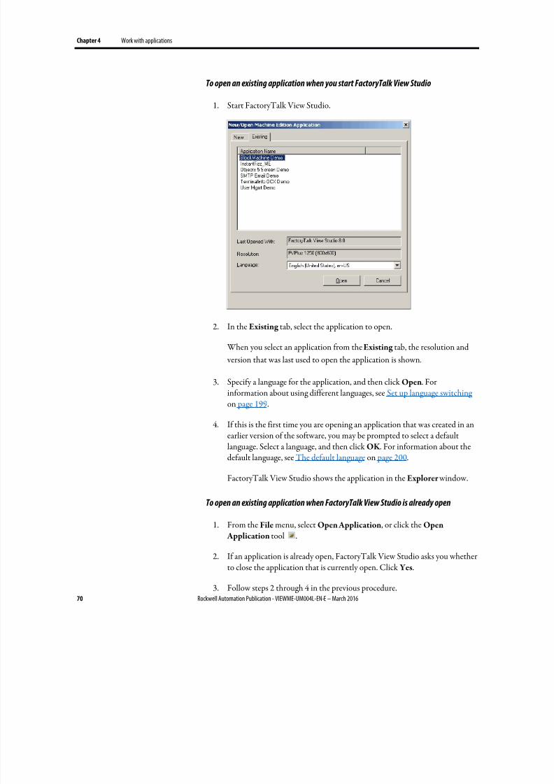
8/17/2019 FactoryTalk® View Machine Edition User's Guide
http://slidepdf.com/reader/full/factorytalk-view-machine-edition-users-guide 70/587
Chapter 4 Work with applications
70 Rockwell Automation Publication - VIEWME-UM004L-EN-E – March 2016
To open an existing application when you start FactoryTalk View Studio
1. Start FactoryTalk View Studio.
2. In the Existing tab, select the application to open.
When you select an application from the Existing tab, the resolution and
version that was last used to open the application is shown.
3.
Specify a language for the application, and then click Open. Forinformation about using different languages, see Set up language switching on page 199.
4. If this is the first time you are opening an application that was created in anearlier version of the software, you may be prompted to select a defaultlanguage. Select a language, and then click OK . For information about thedefault language, see The default language on page 200.
FactoryTalk View Studio shows the application in the Explorer window.
To open an existing application when FactoryTalk View Studio is already open
1.
From the File menu, select Open Application, or click the Open Application tool .
2. If an application is already open, FactoryTalk View Studio asks you whetherto close the application that is currently open. Click Yes.
3. Follow steps 2 through 4 in the previous procedure.
8/17/2019 FactoryTalk® View Machine Edition User's Guide
http://slidepdf.com/reader/full/factorytalk-view-machine-edition-users-guide 71/587
Work with applications Chapter 4
Rockwell Automation Publication - VIEWME-UM004L-EN-E – March 2016 71
To open an application you used recently
1. From the File menu, select Recent Applications, and then click the nameof the application to open.
2. If an application is already open, FactoryTalk View Studio asks you whetherto close the application that is currently open. Click Yes.
The application opens. For applications with multiple languages, the
language you used most recently opens. For information about using
different languages, see Set up language switching on page 199.
Problems opening applications
If you have trouble opening an application in FactoryTalk View Studio, the problem could be a Microsoft Windows security setting. You must have read and write access to the folder that contains the HMI projects. For example, if youbelong to the Windows user group called Power Users, and the group does nothave write access to the HMI projects folder, you won’t be able to openapplications in FactoryTalk View.
The default location for the HMI projects folder is \Users\Public\Public
Documents\RSView Enterprise\ME
For more information about security, see Set up security on page 175.
To set up write access for any Windows Security Group
1. Right-click the HMI projects folder, and then select Properties.
2. In the Security tab of the Properties dialog box, select a Windows SecurityGroup (for example, Power Users) from the list of groups and user names.
3. In the Permissions box below the list, select Full Control, and then select Allow .
Open multiple applications
To open two applications at the same time, for example to copy images andgraphic objects between applications, start two instances of FactoryTalk ViewStudio.
To view a graphic display in different languages at the same time, open theapplication multiple times and select a different language each time you open it.
8/17/2019 FactoryTalk® View Machine Edition User's Guide
http://slidepdf.com/reader/full/factorytalk-view-machine-edition-users-guide 72/587
Chapter 4 Work with applications
72 Rockwell Automation Publication - VIEWME-UM004L-EN-E – March 2016
Open and edit applications from earlier versions of RSView or
FactoryTalk View ME
You can open and edit applications from RSView 3.10, 3.20, and FactoryTalk View 4.0, 5.0, 6.0, 6.10, 7.0, 8.0, and 8.10. When you are finished editing, you cancreate runtime application files for ME Station version 5.0, 5.10, 6.0, 6.10, 7.0, 8.0,8.10, and 8.20. This allows you to continue running your applications on existingterminals, without upgrading all your software.
The application is converted to the current version of FactoryTalk View when youimport it, but when you create the runtime application file you can save it back tothe earlier version.
If the application uses a feature that is not supported by the runtime version, you will not be able to create the runtime application file. When you create theruntime application file, it uses the application’s current language. You can createas many different runtime application files, in as many different languages, as you want.
For information about importing applications, see Import applications on page 66.
For information about the features supported in different versions of FactoryTalk View and RSView, see Features supported in different versions of FactoryTalk View on page 561.
For information about using multiple languages, see Set up language switching on
page 199.
For information about using global objects, see Use graphic displays on page303.Panel
Close an application
To close an application
• From the File menu, select Close Application.
If there are any unsaved changes in open editors, FactoryTalk View Studio
asks you whether to save the changes before closing the application.
To close an application and exit FactoryTalk View Studio at the same time
• Click the Close button at the right end of the FactoryTalk View Studio
title bar .
8/17/2019 FactoryTalk® View Machine Edition User's Guide
http://slidepdf.com/reader/full/factorytalk-view-machine-edition-users-guide 73/587
Work with applications Chapter 4
Rockwell Automation Publication - VIEWME-UM004L-EN-E – March 2016 73
If there are any unsaved changes in open editors, FactoryTalk View Studio
asks you whether to save the changes before closing.
Use the Application Manager tool to:
• Rename applications
• Copy applications
• Delete applications
• Create a compressed backup copy of an application, with the file extension.apa
• Restore an application from the backup file, with the file extension .apa
• Restore a legacy project backup file (with the file extension .mea) from an
earlier release of FactoryTalk View Studio, and convert it to the current version
• Restore a runtime application file, with the file extension .mer, to adevelopment application, with the file extension .med. For moreinformation, see Convert runtime application files to developmentapplications on page 227.
To start the Application Manager tool, do one of the following
• In FactoryTalk View Studio, from the Tools menu, select Application
Manager .
• From Windows Start menu, select Programs > Rockwell Software >
FactoryTalk View > Tools > Application Manager .
For details about using the tool, see the Application Manager Help.
Project settings determine the general appearance of your runtime application,such as the size and position of the project window and whether a title bar appearsin the project window. You can also change the setting for running CompactMachine Edition applications, and enable automatic logout of the current user.
Since project settings affect how your graphic displays look, specify the settingsbefore creating graphic displays.
Project window size and runtime screen resolution
This section describes the difference between project window size and runtimescreen resolution, and describes how these two settings can affect the behavior of your application at runtime.
Rename, copy, delete, backup, and restore applications
About project settings
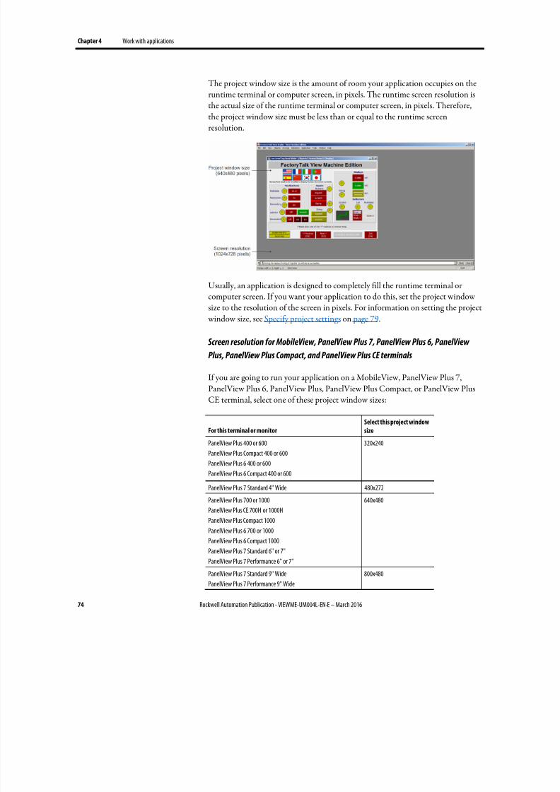
8/17/2019 FactoryTalk® View Machine Edition User's Guide
http://slidepdf.com/reader/full/factorytalk-view-machine-edition-users-guide 74/587
Chapter 4 Work with applications
74 Rockwell Automation Publication - VIEWME-UM004L-EN-E – March 2016
The project window size is the amount of room your application occupies on theruntime terminal or computer screen, in pixels. The runtime screen resolution isthe actual size of the runtime terminal or computer screen, in pixels. Therefore,the project window size must be less than or equal to the runtime screenresolution.
Usually, an application is designed to completely fill the runtime terminal orcomputer screen. If you want your application to do this, set the project windowsize to the resolution of the screen in pixels. For information on setting the project window size, see Specify project settings on page 79.
Screen resolution for MobileView, PanelView Plus 7, PanelView Plus 6, PanelView
Plus, PanelView Plus Compact, and PanelView Plus CE terminals
If you are going to run your application on a MobileView, PanelView Plus 7,PanelView Plus 6, PanelView Plus, PanelView Plus Compact, or PanelView PlusCE terminal, select one of these project window sizes:
For this terminal or monitor
Select this project window
size
PanelView Plus 400 or 600
PanelView Plus Compact 400 or 600
PanelView Plus 6 400 or 600
PanelView Plus 6 Compact 400 or 600
320x240
PanelView Plus 7 Standard 4" Wide 480x272PanelView Plus 700 or 1000
PanelView Plus CE 700H or 1000H
PanelView Plus Compact 1000
PanelView Plus 6 700 or 1000
PanelView Plus 6 Compact 1000
PanelView Plus 7 Standard 6" or 7"
PanelView Plus 7 Performance 6" or 7"
640x480
PanelView Plus 7 Standard 9" Wide
PanelView Plus 7 Performance 9" Wide
800x480
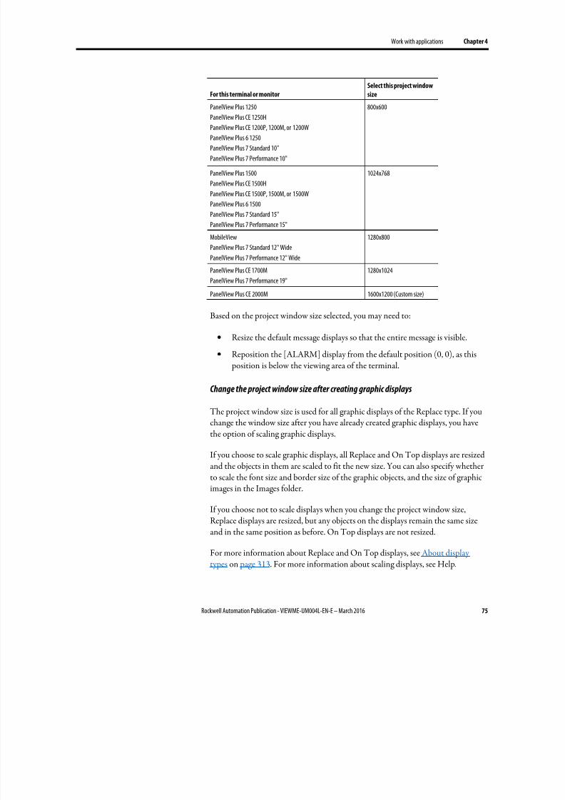
8/17/2019 FactoryTalk® View Machine Edition User's Guide
http://slidepdf.com/reader/full/factorytalk-view-machine-edition-users-guide 75/587
Work with applications Chapter 4
Rockwell Automation Publication - VIEWME-UM004L-EN-E – March 2016 75
For this terminal or monitor
Select this project window
size
PanelView Plus 1250
PanelView Plus CE 1250H
PanelView Plus CE 1200P, 1200M, or 1200W
PanelView Plus 6 1250
PanelView Plus 7 Standard 10"
PanelView Plus 7 Performance 10"
800x600
PanelView Plus 1500
PanelView Plus CE 1500H
PanelView Plus CE 1500P, 1500M, or 1500W
PanelView Plus 6 1500
PanelView Plus 7 Standard 15"
PanelView Plus 7 Performance 15"
1024x768
MobileView
PanelView Plus 7 Standard 12" WidePanelView Plus 7 Performance 12" Wide
1280x800
PanelView Plus CE 1700M
PanelView Plus 7 Performance 19"
1280x1024
PanelView Plus CE 2000M 1600x1200 (Custom size)
Based on the project window size selected, you may need to:
• Resize the default message displays so that the entire message is visible.
• Reposition the [ALARM] display from the default position (0, 0), as this position is below the viewing area of the terminal.
Change the project window size after creating graphic displays
The project window size is used for all graphic displays of the Replace type. If youchange the window size after you have already created graphic displays, you havethe option of scaling graphic displays.
If you choose to scale graphic displays, all Replace and On Top displays are resizedand the objects in them are scaled to fit the new size. You can also specify whetherto scale the font size and border size of the graphic objects, and the size of graphicimages in the Images folder.
If you choose not to scale displays when you change the project window size,Replace displays are resized, but any objects on the displays remain the same sizeand in the same position as before. On Top displays are not resized.
For more information about Replace and On Top displays, see About displaytypes on page 313. For more information about scaling displays, see Help.
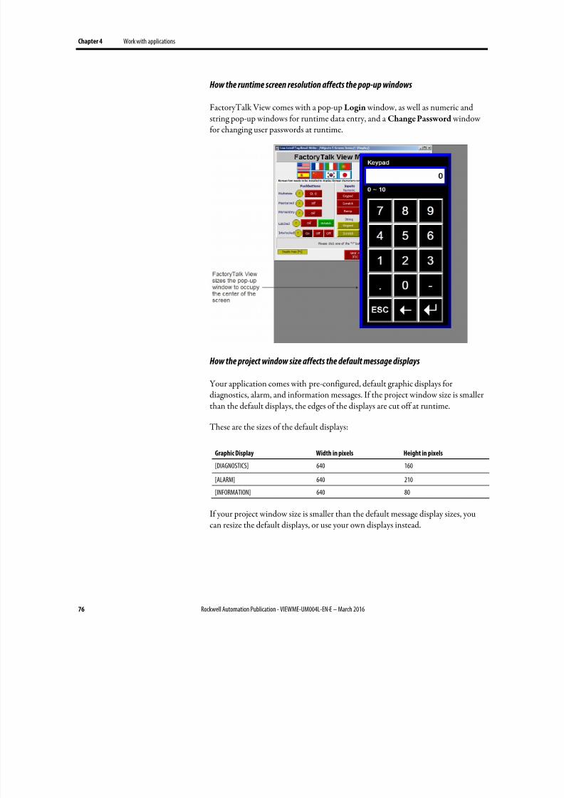
8/17/2019 FactoryTalk® View Machine Edition User's Guide
http://slidepdf.com/reader/full/factorytalk-view-machine-edition-users-guide 76/587
Chapter 4 Work with applications
76 Rockwell Automation Publication - VIEWME-UM004L-EN-E – March 2016
How the runtime screen resolution affects the pop-up windows
FactoryTalk View comes with a pop-up Login window, as well as numeric and
string pop-up windows for runtime data entry, and aChange Password
windowfor changing user passwords at runtime.
How the project window size affects the default message displays
Your application comes with pre-configured, default graphic displays fordiagnostics, alarm, and information messages. If the project window size is smallerthan the default displays, the edges of the displays are cut off at runtime.
These are the sizes of the default displays:
Graphic Display Width in pixels Height in pixels
[DIAGNOSTICS] 640 160
[ALARM] 640 210
[INFORMATION] 640 80
If your project window size is smaller than the default message display sizes, youcan resize the default displays, or use your own displays instead.
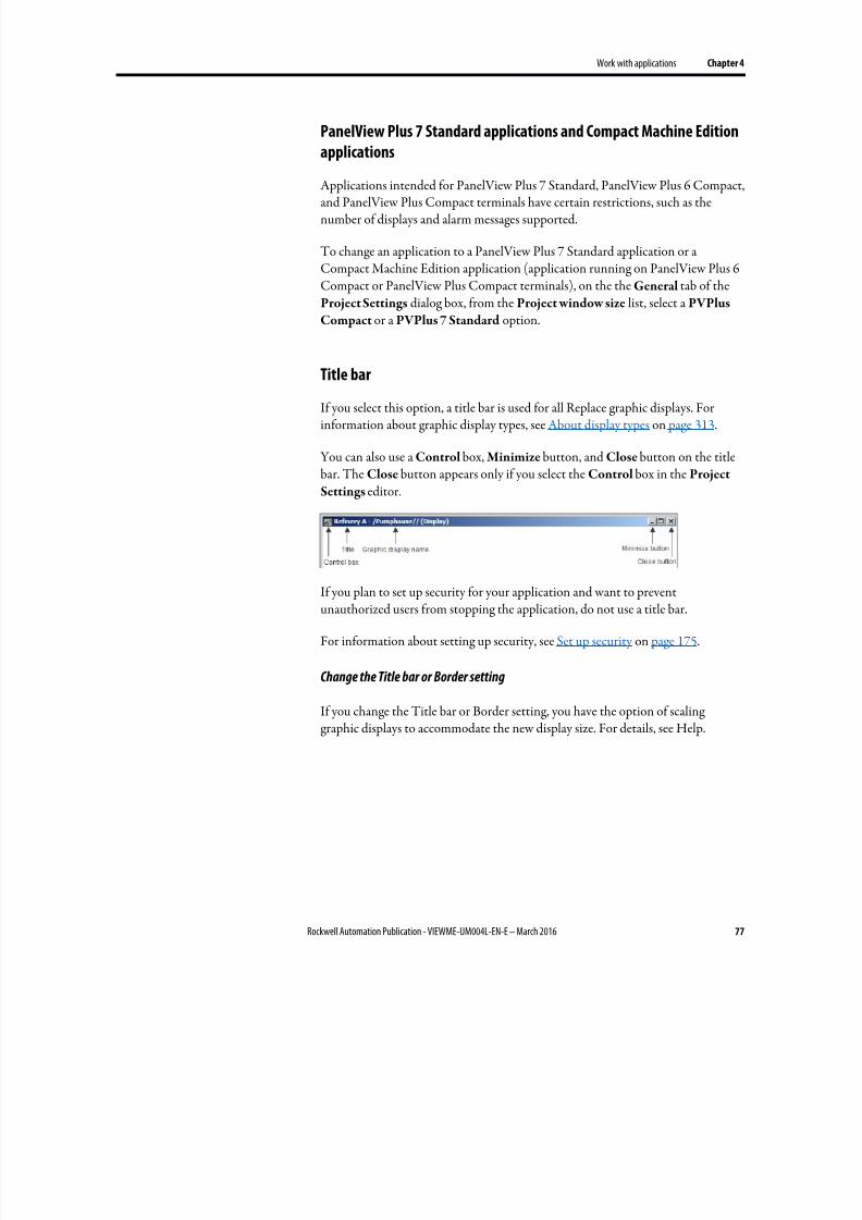
8/17/2019 FactoryTalk® View Machine Edition User's Guide
http://slidepdf.com/reader/full/factorytalk-view-machine-edition-users-guide 77/587
Work with applications Chapter 4
Rockwell Automation Publication - VIEWME-UM004L-EN-E – March 2016 77
PanelView Plus 7 Standard applications and Compact Machine Edition
applications
Applications intended for PanelView Plus 7 Standard, PanelView Plus 6 Compact,and PanelView Plus Compact terminals have certain restrictions, such as thenumber of displays and alarm messages supported.
To change an application to a PanelView Plus 7 Standard application or aCompact Machine Edition application (application running on PanelView Plus 6Compact or PanelView Plus Compact terminals), on the the General tab of theProject Settings dialog box, from the Project window size list, select a PVPlus
Compact or a PVPlus 7 Standard option.
Title bar
If you select this option, a title bar is used for all Replace graphic displays. Forinformation about graphic display types, see About display types on page 313.
You can also use a Control box, Minimize button, and Close button on the titlebar. The Close button appears only if you select the Control box in the Project
Settings editor.
If you plan to set up security for your application and want to preventunauthorized users from stopping the application, do not use a title bar.
For information about setting up security, see Set up security on page 175.
Change the Title bar or Border setting
If you change the Title bar or Border setting, you have the option of scalinggraphic displays to accommodate the new display size. For details, see Help.
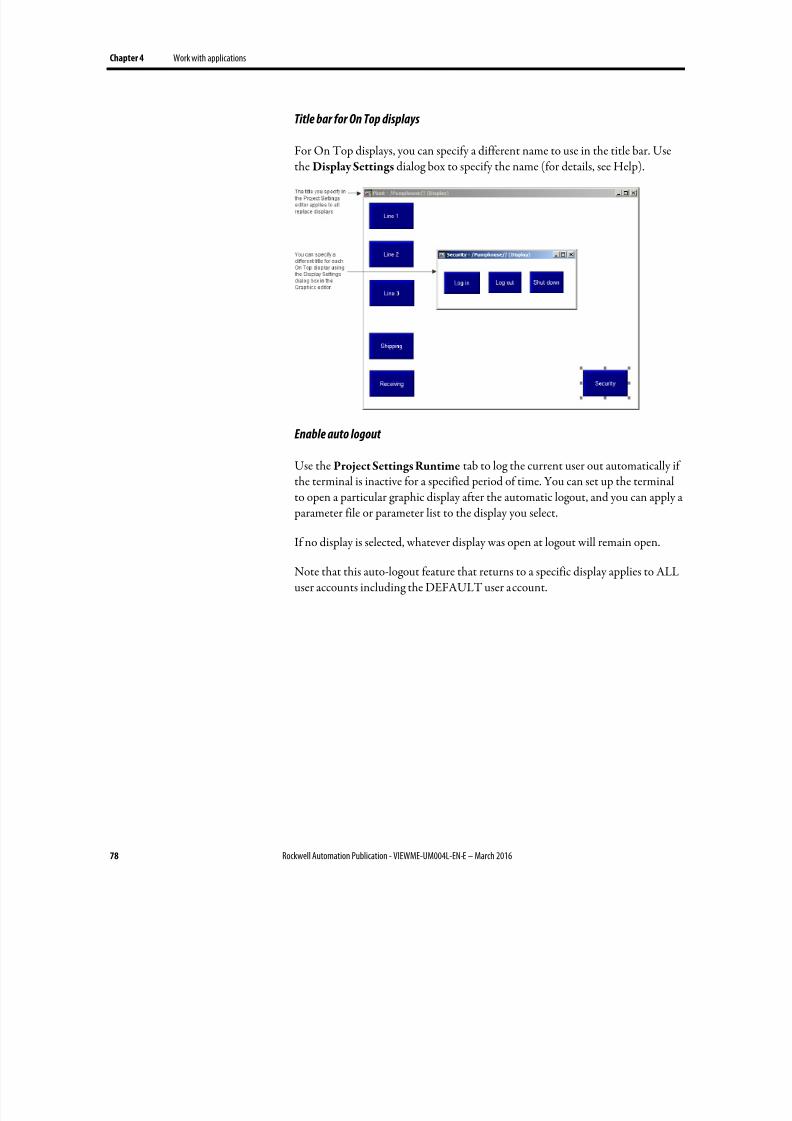
8/17/2019 FactoryTalk® View Machine Edition User's Guide
http://slidepdf.com/reader/full/factorytalk-view-machine-edition-users-guide 78/587
Chapter 4 Work with applications
78 Rockwell Automation Publication - VIEWME-UM004L-EN-E – March 2016
Title bar for On Top displays
For On Top displays, you can specify a different name to use in the title bar. Usethe Display Settings dialog box to specify the name (for details, see Help).
Enable auto logout
Use the Project Settings Runtime tab to log the current user out automatically ifthe terminal is inactive for a specified period of time. You can set up the terminalto open a particular graphic display after the automatic logout, and you can apply a parameter file or parameter list to the display you select.
If no display is selected, whatever display was open at logout will remain open.
Note that this auto-logout feature that returns to a specific display applies to ALLuser accounts including the DEFAULT user account.
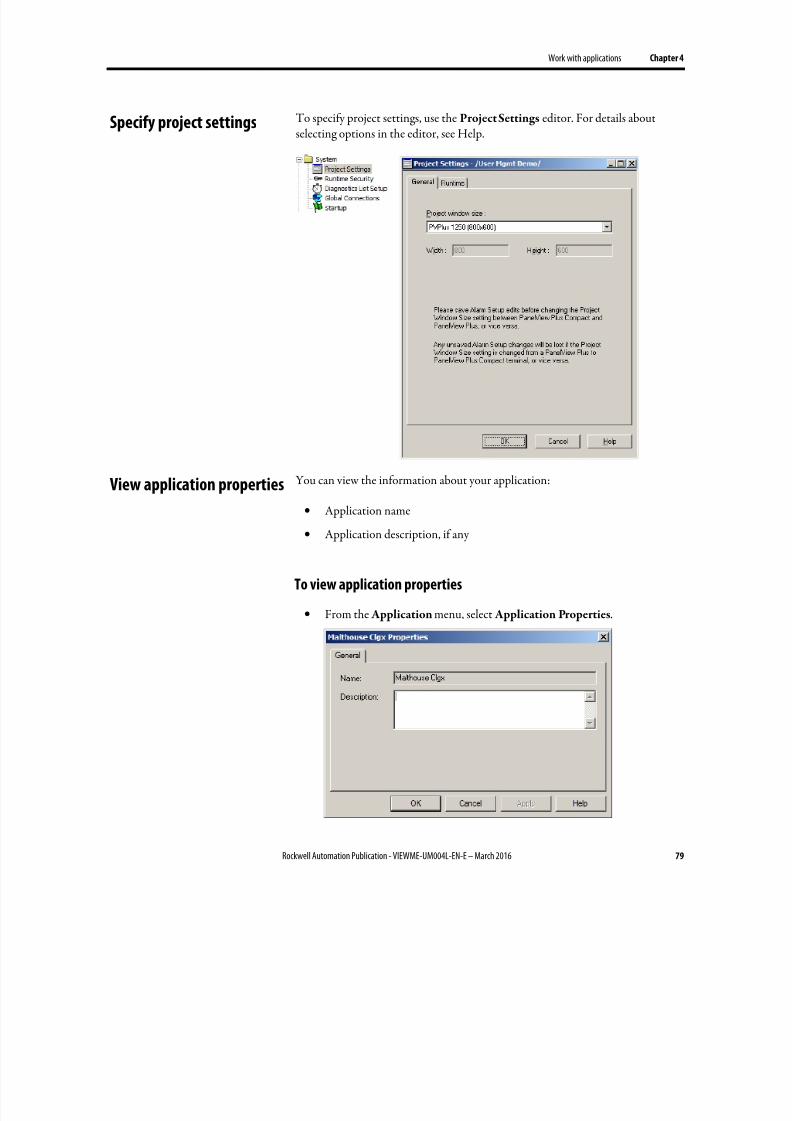
8/17/2019 FactoryTalk® View Machine Edition User's Guide
http://slidepdf.com/reader/full/factorytalk-view-machine-edition-users-guide 79/587
Work with applications Chapter 4
Rockwell Automation Publication - VIEWME-UM004L-EN-E – March 2016 79
To specify project settings, use the Project Settings editor. For details aboutselecting options in the editor, see Help.
You can view the information about your application:
• Application name
• Application description, if any
To view application properties
• From the Application menu, select Application Properties.
Specify project settings
View application properties
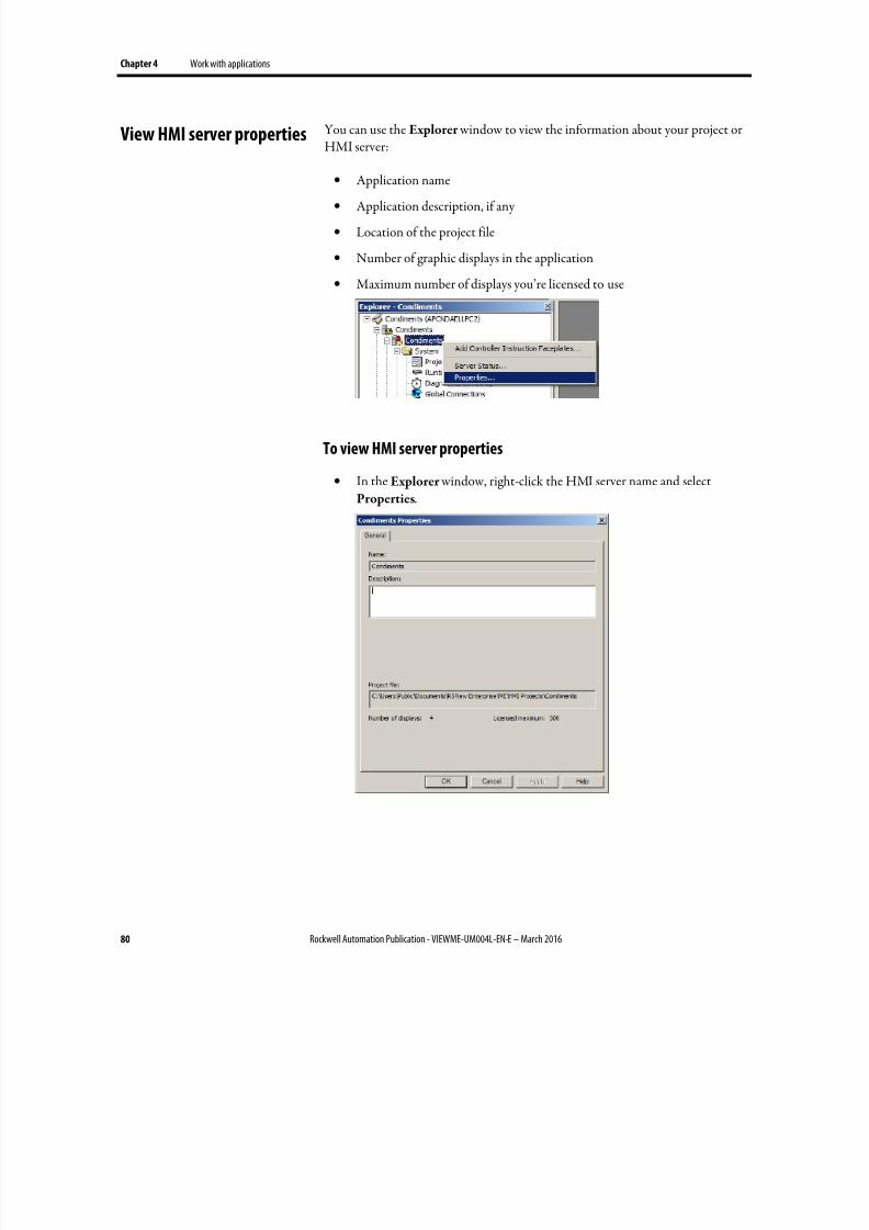
8/17/2019 FactoryTalk® View Machine Edition User's Guide
http://slidepdf.com/reader/full/factorytalk-view-machine-edition-users-guide 80/587
Chapter 4 Work with applications
80 Rockwell Automation Publication - VIEWME-UM004L-EN-E – March 2016
You can use the Explorer window to view the information about your project orHMI server:
• Application name
• Application description, if any
• Location of the project file
• Number of graphic displays in the application
• Maximum number of displays you’re licensed to use
To view HMI server properties
• In the Explorer window, right-click the HMI server name and selectProperties.
View HMI server properties
8/17/2019 FactoryTalk® View Machine Edition User's Guide
http://slidepdf.com/reader/full/factorytalk-view-machine-edition-users-guide 81/587
Rockwell Automation Publication - VIEWME-UM004L-EN-E – March 2016 81
Chapter 5
Set up communications
This chapter describes:
• Data servers
• OLE for Process Control (OPC) communications
• Creating data servers and setting up communications
Data servers provide access to devices on the network, making it possible tobrowse, read, and write values from FactoryTalk View applications.
FactoryTalk View ME supports the following types of data servers:
• Rockwell Automation Device Servers RSLinx Enterprise is the recommended data server for all RockwellAutomation devices and networks. RSLinx Enterprise does not requireactivation or licensing and can be installed as often as needed in anyapplication.
• OPC Data Servers are any data server that supports the OPC-DataAccess
Standard v2.05a.The OPC Foundation is a non-profit organization that provides standardsand technology that enables software from different vendors to worktogether. The following OPC Data Access v2.05a servers are available withFactoryTalk View ME.
• KepServer Enterprise is used to communicate with non-RockwellAutomation devices like Siemens or Modicon controllers.KepServer Enterprise does not require activation or licensing forFactoryTalk View ME.
• RSLinx Classic can only be used with FactoryTalk View ME Station
and should only be considered in the following situations:
• CIP to non-CIP routing is required to reach the device.
• Unsolicited messages are used to send data from controllers.
• Alias topics (multiple paths to the same device) are required.
FactoryTalk View ME supports OPC communication on the PanelView Plusfamily of terminals for use with only KEPServer Enterprise. FactoryTalk View ME
About data servers
About OPC communications
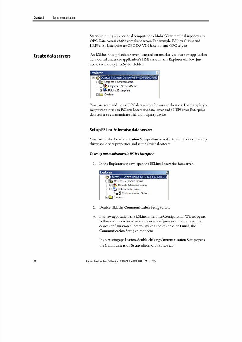
8/17/2019 FactoryTalk® View Machine Edition User's Guide
http://slidepdf.com/reader/full/factorytalk-view-machine-edition-users-guide 82/587
Chapter 5 Set up communications
82 Rockwell Automation Publication - VIEWME-UM004L-EN-E – March 2016
Station running on a personal computer or a MobileView terminal supports anyOPC Data Access v2.05a compliant server. For example, RSLinx Classic andKEPServer Enterprise are OPC DA V2.05a compliant OPC servers.
An RSLinx Enterprise data server is created automatically with a new application.It is located under the application’s HMI server in the Explorer window, justabove the FactoryTalk System folder.
You can create additional OPC data servers for your application. For example, youmight want to use an RSLinx Enterprise data server and a KEPServer Enterprisedata server to communicate with a third party device.
Set up RSLinx Enterprise data servers
You can use the Communication Setup editor to add drivers, add devices, set updriver and device properties, and set up device shortcuts.
To set up communications in RSLinx Enterprise
1. In the Explorer window, open the RSLinx Enterprise data server.
2. Double-click the Communication Setup editor.
3. In a new application, the RSLinx Enterprise Configuration Wizard opens.Follow the instructions to create a new configuration or use an existingdevice configuration. Once you make a choice and click Finish, theCommunication Setup editor opens.
In an existing application, double-clickingCommunication Setup opens
the Communication Setup editor, with its two tabs.
Create data servers
8/17/2019 FactoryTalk® View Machine Edition User's Guide
http://slidepdf.com/reader/full/factorytalk-view-machine-edition-users-guide 83/587
Set up communications Chapter 5
Rockwell Automation Publication - VIEWME-UM004L-EN-E – March 2016 83
• The Design (Local) tab is for establishing the location of thetags/addresses for editing. The tags/addresses can be online with acontroller or other data server, or an offline controller file. This willenable the Tag Browser to find the tags/addresses.
• The Runtime (Target) tab is for identifying the connection from theruntime computer or terminal to the controller or other data server. Ifthe paths are the same, use the Copy button to copy the Designconfiguration to the Runtime tab.
For more information, see Help for RSLinx Enterprise.
Set up an OPC data server
If you need to connect third party devices, use a KEPServer Enterprise data server.
If you have one of the situations described above and you are using a personalcomputer or a MobileView terminal in your application, use RSLinx Classic dataserver.
If you need to view or use tag names when you are not connected to a device, youcan set up a cache that will read in tag names from the device and enable them tobe used when the device is offline.
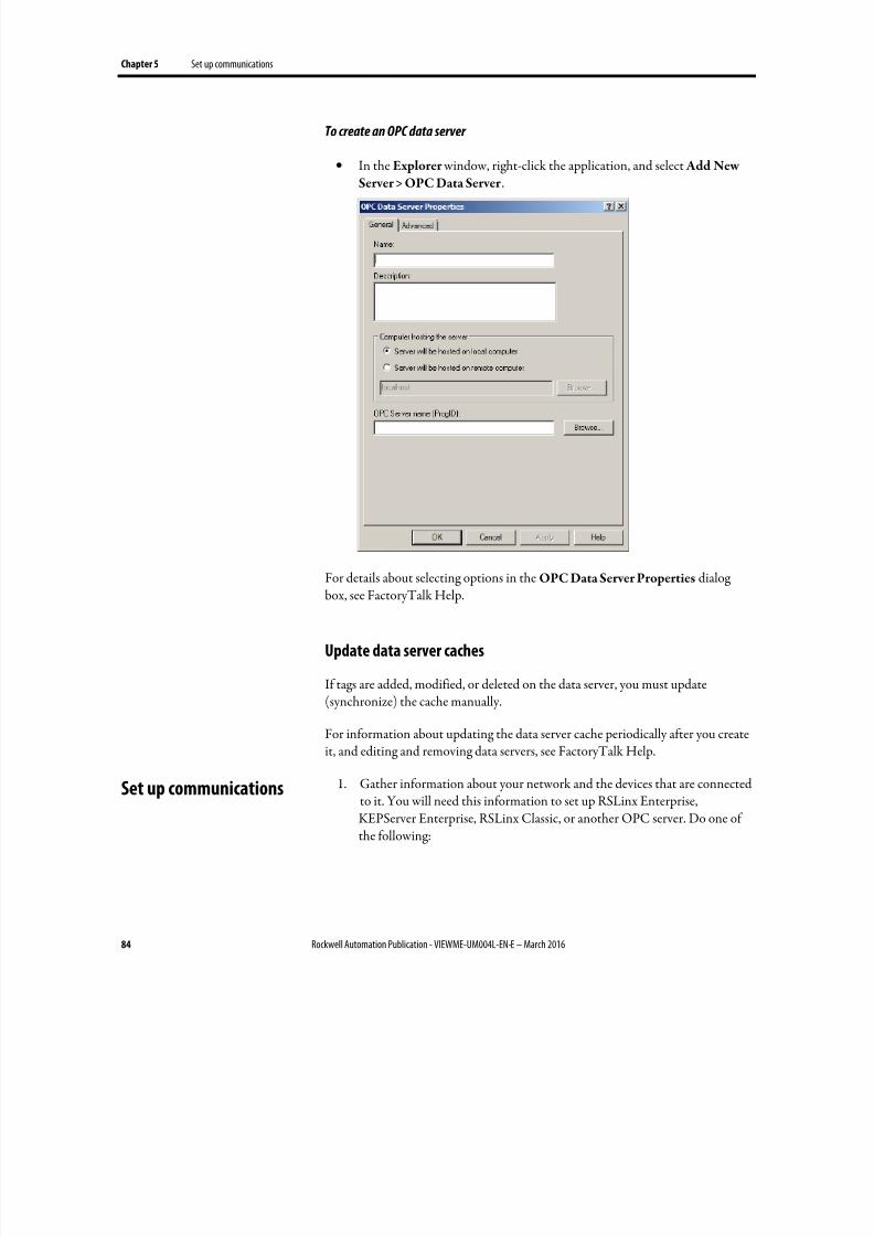
8/17/2019 FactoryTalk® View Machine Edition User's Guide
http://slidepdf.com/reader/full/factorytalk-view-machine-edition-users-guide 84/587
Chapter 5 Set up communications
84 Rockwell Automation Publication - VIEWME-UM004L-EN-E – March 2016
To create an OPC data server
• In the Explorer window, right-click the application, and select Add New
Server > OPC Data Server .
For details about selecting options in the OPC Data Server Properties dialogbox, see FactoryTalk Help.
Update data server caches
If tags are added, modified, or deleted on the data server, you must update(synchronize) the cache manually.
For information about updating the data server cache periodically after you createit, and editing and removing data servers, see FactoryTalk Help.
1. Gather information about your network and the devices that are connectedto it. You will need this information to set up RSLinx Enterprise,KEPServer Enterprise, RSLinx Classic, or another OPC server. Do one ofthe following:
Set up communications
8/17/2019 FactoryTalk® View Machine Edition User's Guide
http://slidepdf.com/reader/full/factorytalk-view-machine-edition-users-guide 85/587
Set up communications Chapter 5
Rockwell Automation Publication - VIEWME-UM004L-EN-E – March 2016 85
• If you want to use KEPServer Enterprise as the OPC server that enablescommunications on your network, set up KEPServer Enterprise on thedevelopment computer. For details, see KEPServer Enterprise Help.
•
If you want to use RSLinx Classic as the OPC server that enablescommunications on your network, set up RSLinx Classic on thedevelopment computer. RSLinx Classic is included on the FactoryTalk View installation DVD. For details, see Getting Results with RSLinx, orsee Help for RSLinx.
RSLinx Classic is available for FactoryTalk View ME Station on
personal computers only.
• If you want to use an OPC server other than RSLinx Classic forcommunications on your network, set up the OPC server on thedevelopment computer. For details, see the documentation supplied
with your OPC server.
2. In FactoryTalk View Studio, create a data server that points to the OPCserver you have installed.
If you are using RSLinx Enterprise for communications, you don’t need to
create a data server because it is created automatically when you create your
FactoryTalk Machine Edition application.
Tip: KEPServer Enterprise is the only OPC Server supported on PanelView Plus 7, PanelView Plus6, PanelView Plus, PanelView Plus Compact, and PanelView Plus CE terminals.
3. If you want to use HMI tags in your application, open the Tags editor, andthen create device tags that point to addresses in devices. For details aboutcreating HMI tags, see Use HMI tags on page 99.
If you do not want to use HMI tags, but instead want to reference addresses
in devices directly, skip this step.
Best practice is to use direct reference tags.
4. In objects in graphic displays, or anywhere else you want access to values in
tags, type the tag name using the syntax for your OPC server, or use the TagBrowser to select tags. For details about using tags, see Work with tags on page 87.
5. Create the runtime application file. For details, see Create runtimeapplications on page 223.
All the necessary tag information is compiled with the runtime application
file.

8/17/2019 FactoryTalk® View Machine Edition User's Guide
http://slidepdf.com/reader/full/factorytalk-view-machine-edition-users-guide 86/587
Chapter 5 Set up communications
86 Rockwell Automation Publication - VIEWME-UM004L-EN-E – March 2016
6. If you are using an OPC server other than RSLinx Enterprise or RSLinxClassic, install the OPC server software on the runtime computer.
For applications that will run on a personal computer, the OPC server can
be on a different (remote) computer than the runtime computer, but the
remote computer must be on the same network as the runtime computer.
8/17/2019 FactoryTalk® View Machine Edition User's Guide
http://slidepdf.com/reader/full/factorytalk-view-machine-edition-users-guide 87/587
Rockwell Automation Publication - VIEWME-UM004L-EN-E – March 2016 87
Chapter 6
Work with tags
This chapter describes:
• Types of tags
• When to use data server tags
• Steps for using data server tags
•
When to use HMI tags• Steps for using HMI tags
• Browse for tags and offline tags
• Use the Tag Browser
• Use tags and expressions in your application
• Log tag values
• Use macros to assign values to tags
For information about creating HMI tags, see Use HMI tags on page 99.
A tag is a logical name for a variable in a device or in local memory (RAM). Forexample, a tag can represent a process variable in a programmable controller.
Data server tags
FactoryTalk View conforms to the OPC DA (Data Access) 2.05a specification forinformation exchange among automation or control applications, field systems ordevices, and business or office applications.
In FactoryTalk View, data servers such as RSLinx Enterprise, RSLinx Classic, andKEPServer Enterprise provide access to OPC-DA-compliant tags. In theFactoryTalk View documentation, the tags you use through a data server are calleddata server tags. For more information about data servers, see Set upcommunications on page 81.
Data server tags include tags found in Logix5000 processors and tags from otherOPC-compliant devices. You use data server tags by providing a direct reference tothe tag’s location, wherever you want your application to use the data.
Types of tags
8/17/2019 FactoryTalk® View Machine Edition User's Guide
http://slidepdf.com/reader/full/factorytalk-view-machine-edition-users-guide 88/587
Chapter 6 Work with tags
88 Rockwell Automation Publication - VIEWME-UM004L-EN-E – March 2016
HMI tags
In addition to direct referencing tags from data servers, FactoryTalk View allows
you to create tags with additional properties such as minimum and maximum values, scale, and offset. These tags can reference values at an external data source,or store values in the runtime computer’s memory. Tags you create in FactoryTalk View are called HMI tags.
The data source
The FactoryTalk View documentation uses the term data source as a generic termthat includes all possible sources of tag data, for both data server tags and HMItags. The data source can be memory or a device such as a programmable controller
or an OPC server. FactoryTalk View writes values to and reads values from thedata source. The data source is set up to exchange information (in the form ofnumeric or string values) between the FactoryTalk View value table and themachine that your application is controlling.
Basic steps for using tags
To use tags, follow these basic steps:
1. If the tag does not exist, create the tag.
•
To use a data server tag, you can use an existing tag in the processor (forexample, a programmable controller), or you can create a new one inthe processor or OPC server. For example, in a Logix5000 processor, you could create the tag using your RSLogix 5000 or Logix Designer programming software.
• To use an HMI tag, you must first create it in the Tags editor. Fordetails, see Use HMI tags on page 99.
2. Browse for or type the name of the tag anywhere you want to connect anobject to data at runtime.
For example, to make a push button change a tag value when it is pressed,
connect the push button to a tag by typing the tag name on the
Connections tab of the push button’s Properties dialog box.
If you don’t know the names of tags, you can browse for them. You can browse while online and connected to a device, or you can browse for tags from an offlinefile, for example a Logix5000 program file. To browse for tags, use the Tag
Browser . For details, see Browse for tags on page 91.
8/17/2019 FactoryTalk® View Machine Edition User's Guide
http://slidepdf.com/reader/full/factorytalk-view-machine-edition-users-guide 89/587
Work with tags Chapter 6
Rockwell Automation Publication - VIEWME-UM004L-EN-E – March 2016 89
Use tag names that don’t exist
You can type the name of a tag that does not exist. If you do this, ensure that you
spell every instance of the tag name consistently, and that when you create the tag, you spell it the same way you did when you referred to it.
For some of the things you want to do in your application, you might not need tocreate HMI tags. Use direct references to tags located in devices instead, forexample, tags located in an OPC server’s database.
Eliminate duplication
Using data server tags allows you to add, modify or delete tags in a device withouthaving to duplicate the changes in the FactoryTalk View HMI tag database.
Use complex data
Some devices, for example, Logix5000 processors, support complex data types,such as arrays and structures. Your controller might have structures that containhundreds of member elements.
Referencing tag values directly eliminates the need for creating an HMI tag foreach member.
Direct reference tags usually update faster than HMI tags. To obtain the bestsystem performance for your application, use direct reference tags where possible.
To use data server tags, complete three basic steps:
1. Create the tag in the OPC server or processor, or use an existing tag in the processor.
The server must understand the syntax of the device it is connected to. You
need only create a tag if you want to browse the server.
Examples of OPC servers include RSLinx Classic and KEPServer
Enterprise. For information about creating tags in OPC servers that have
their own tag database, see the documentation provided with the server.
For information about creating tags in a Logix5000 processor, see the
documentation for your device programming software.
2. Create a data server in FactoryTalk View, if your application does notalready have one. Every new FactoryTalk View Machine applicationincludes a RSLinx Enterprise data server automatically.
When to use data server
tags
Steps for using data server
tags
8/17/2019 FactoryTalk® View Machine Edition User's Guide
http://slidepdf.com/reader/full/factorytalk-view-machine-edition-users-guide 90/587
Chapter 6 Work with tags
90 Rockwell Automation Publication - VIEWME-UM004L-EN-E – March 2016
For more information, see Set up communications on page 81.
3. In graphic displays, data log models, or anywhere else you want to use a tag’s value, create a direct reference to the tag. At runtime, the tag’s value is passed to the graphic display or data log model.
Use HMI tags to manipulate tag data and to store tag values in the runtimecomputer’s memory.
Scale, offset, or provide a range for data
Use HMI tags if the data server you are using does not provide for:
• Scale or offset a value.
• Set minimum or maximum limits on a value (that is, providing a range of values).
Scale and offset
The scale and offset modify the raw data that comes from and goes to the
programmable controller before the data is saved in the computer’s memory(called the value table). The scale and offset also modify the value specified in
FactoryTalk View before it is written to the programmable controller.
The scale is a multiplication factor — the value from the programmable controlleris multiplied by the scale.
The offset is a fixed value — after the value from the programmable controller ismultiplied by the scale, the offset amount is added.
Minimum and maximum
HMI tags allow you to set a minimum value and a maximum value that can be written to the programmable controller or server.
These values do not affect what is read from the programmable controller orserver.
For example, if you specify a minimum of 0 and a maximum of 100, FactoryTalk View would be able to read a value of 200 from a programmable controller andstore it in the value table, but would not be able to write this value to the programmable controller.
For more information about minimum and maximum, and scale and offset, seeHelp.
When to use HMI tags
8/17/2019 FactoryTalk® View Machine Edition User's Guide
http://slidepdf.com/reader/full/factorytalk-view-machine-edition-users-guide 91/587
Work with tags Chapter 6
Rockwell Automation Publication - VIEWME-UM004L-EN-E – March 2016 91
Store values in FactoryTalk View memory
A memory tag can be used to store values without the need for an attached or
accessible device.
For example, you might need to store a value in memory:
• To store the result of a calculation.
• Temporarily, for example, a counter or index.
• To maintain information about the system’s current state, for example which graphic display was last opened.
For information about creating HMI memory tags, see Use HMI tags on page 99.
To use HMI tags, complete two basic steps:
1. In the Tags editor in FactoryTalk View, create a tag. HMI tags can be usedas an internal storage location. Optionally you can map the tag name to anOPC tag or device address.
2. For more information, see Use HMI tags on page 99.
3. In graphic displays, alarm triggers, or anywhere else you want to use a tag’s value, assign the tag. At runtime, the tag’s value is passed to the graphicdisplay or alarm system.
You don’t have to remember the path and name of a tag to use it in yourapplication. Whenever you need to use a tag, you can open the Tag Browser andselect the tag to use.
To open the Tag Browser
• In most editors, click the Browse button in the Tags column.
• In the Expression editor, position the cursor where you want to insert a tagname, and then click Tags.
•
In the Parameters editor, double-click where you want to insert a tag name.
Steps for using HMI tags
Browse for tags
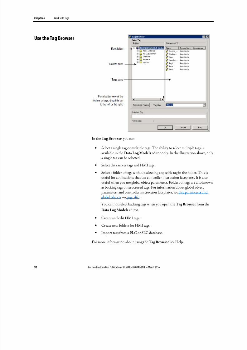
8/17/2019 FactoryTalk® View Machine Edition User's Guide
http://slidepdf.com/reader/full/factorytalk-view-machine-edition-users-guide 92/587
Chapter 6 Work with tags
92 Rockwell Automation Publication - VIEWME-UM004L-EN-E – March 2016
In the Tag Browser , you can:
• Select a single tag or multiple tags. The ability to select multiple tags isavailable in the Data Log Models editor only. In the illustration above, onlya single tag can be selected.
•
Select data server tags and HMI tags.
• Select a folder of tags without selecting a specific tag in the folder. This isuseful for applications that use controller instruction faceplates. It is alsouseful when you use global object parameters. Folders of tags are also knownas backing tags or structured tags. For information about global object parameters and controller instruction faceplates, see Use parameters andglobal objects on page 461.
You cannot select backing tags when you open the Tag Browser from the
Data Log Models editor.
•
Create and edit HMI tags.
• Create new folders for HMI tags.
• Import tags from a PLC or SLC database.
For more information about using the Tag Browser , see Help.
Use the Tag Browser
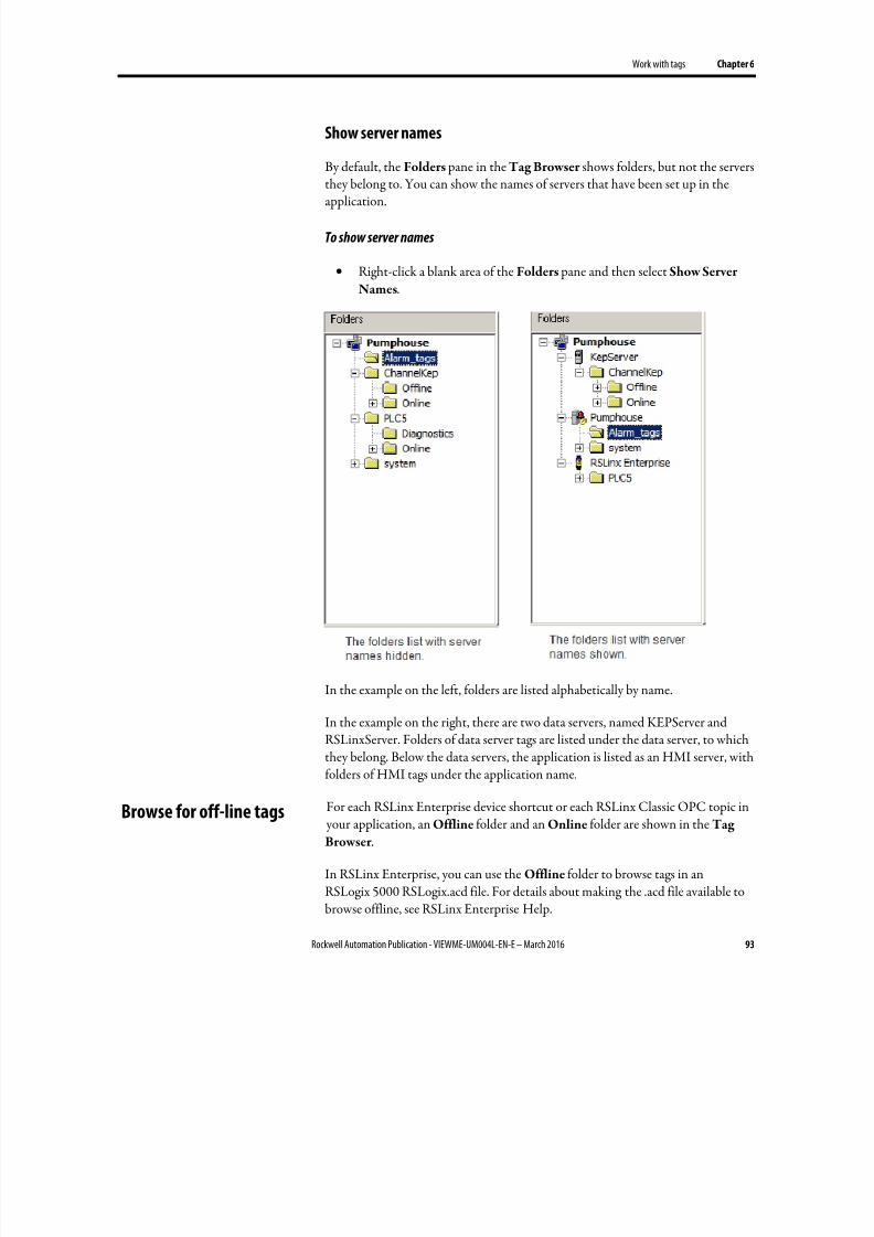
8/17/2019 FactoryTalk® View Machine Edition User's Guide
http://slidepdf.com/reader/full/factorytalk-view-machine-edition-users-guide 93/587
Work with tags Chapter 6
Rockwell Automation Publication - VIEWME-UM004L-EN-E – March 2016 93
Show server names
By default, the Folders pane in the Tag Browser shows folders, but not the servers
they belong to. You can show the names of servers that have been set up in theapplication.
To show server names
• Right-click a blank area of the Folders pane and then select Show Server
Names.
In the example on the left, folders are listed alphabetically by name.
In the example on the right, there are two data servers, named KEPServer andRSLinxServer. Folders of data server tags are listed under the data server, to whichthey belong. Below the data servers, the application is listed as an HMI server, withfolders of HMI tags under the application name.
For each RSLinx Enterprise device shortcut or each RSLinx Classic OPC topic in your application, an Offline folder and an Online folder are shown in the Tag
Browser .
In RSLinx Enterprise, you can use the Offline folder to browse tags in anRSLogix 5000 RSLogix.acd file. For details about making the .acd file available tobrowse offline, see RSLinx Enterprise Help.
Browse for off-line tags
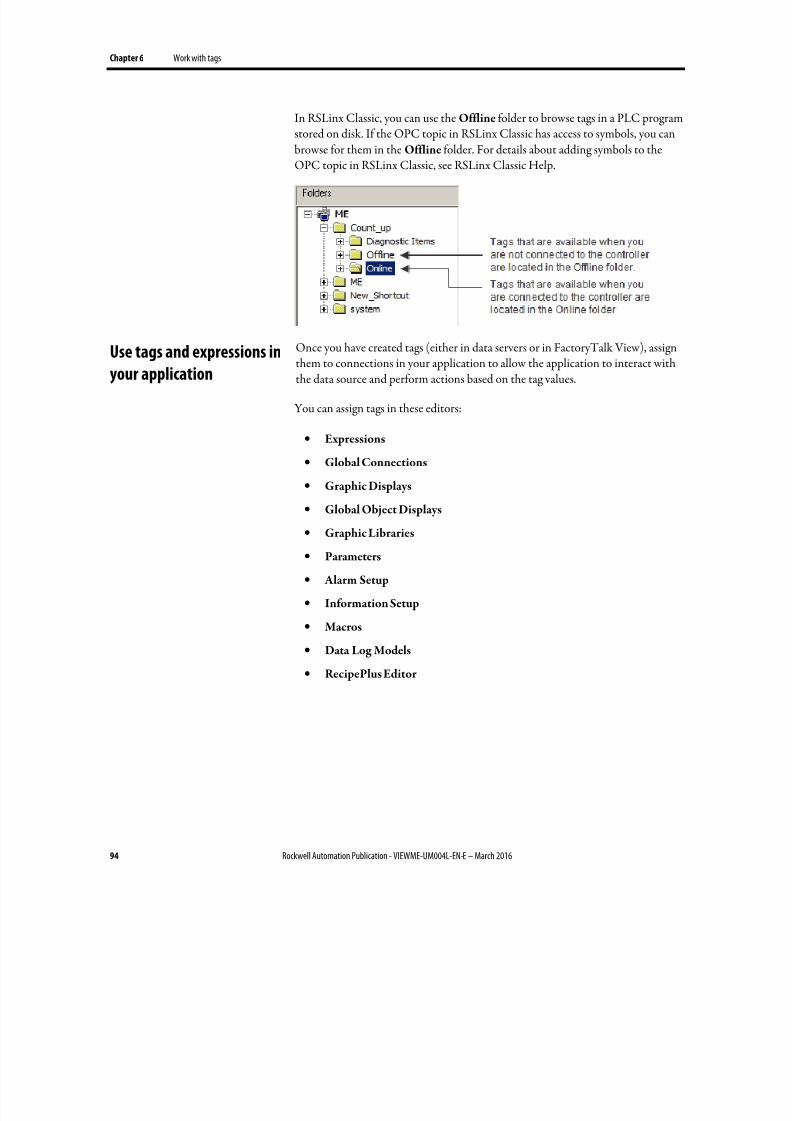
8/17/2019 FactoryTalk® View Machine Edition User's Guide
http://slidepdf.com/reader/full/factorytalk-view-machine-edition-users-guide 94/587
Chapter 6 Work with tags
94 Rockwell Automation Publication - VIEWME-UM004L-EN-E – March 2016
In RSLinx Classic, you can use the Offline folder to browse tags in a PLC programstored on disk. If the OPC topic in RSLinx Classic has access to symbols, you canbrowse for them in the Offline folder. For details about adding symbols to theOPC topic in RSLinx Classic, see RSLinx Classic Help.
Once you have created tags (either in data servers or in FactoryTalk View), assignthem to connections in your application to allow the application to interact withthe data source and perform actions based on the tag values.
You can assign tags in these editors:
• Expressions
• Global Connections
• Graphic Displays
• Global Object Displays
• Graphic Libraries
• Parameters
• Alarm Setup
• Information Setup
• Macros
• Data Log Models
• RecipePlus Editor
Use tags and expressions inyour application
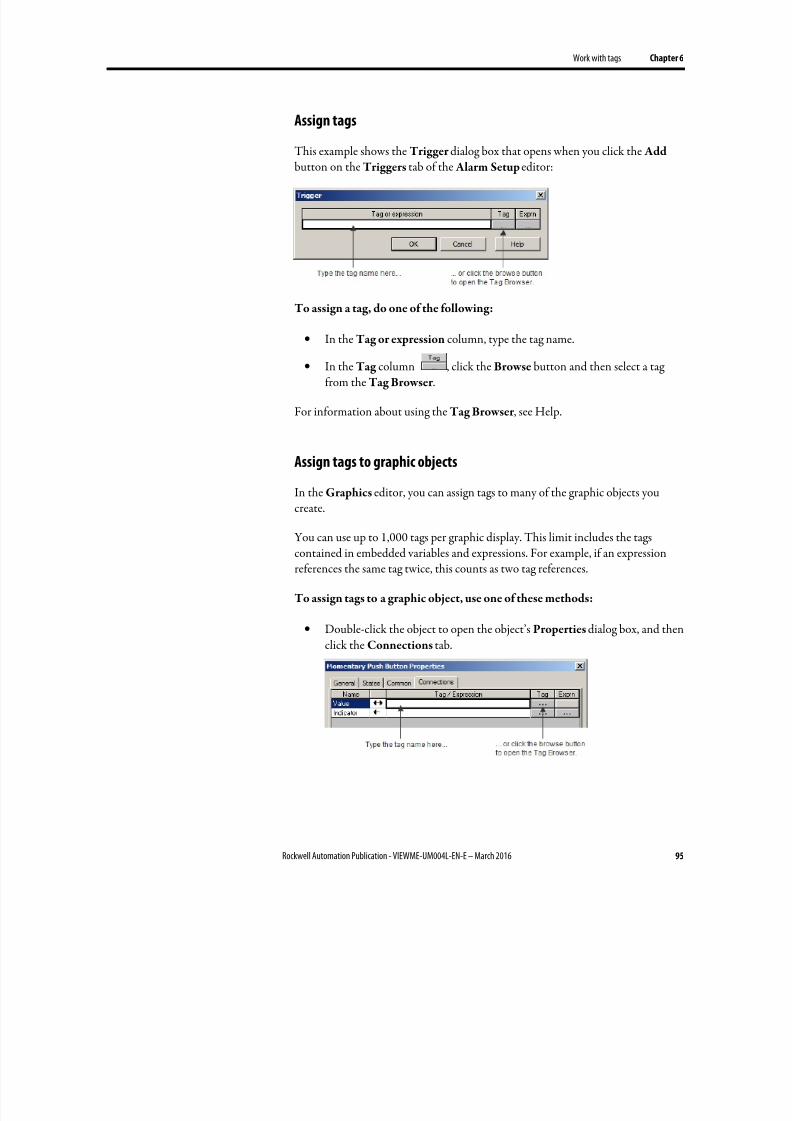
8/17/2019 FactoryTalk® View Machine Edition User's Guide
http://slidepdf.com/reader/full/factorytalk-view-machine-edition-users-guide 95/587
Work with tags Chapter 6
Rockwell Automation Publication - VIEWME-UM004L-EN-E – March 2016 95
Assign tags
This example shows the Trigger dialog box that opens when you click the Add
button on the Triggers tab of the Alarm Setup editor:
To assign a tag, do one of the following:
• In the Tag or expression column, type the tag name.
• In the Tag column , click the Browse button and then select a tagfrom the Tag Browser .
For information about using the Tag Browser , see Help.
Assign tags to graphic objects
In the Graphics editor, you can assign tags to many of the graphic objects youcreate.
You can use up to 1,000 tags per graphic display. This limit includes the tagscontained in embedded variables and expressions. For example, if an expressionreferences the same tag twice, this counts as two tag references.
To assign tags to a graphic object, use one of these methods:
• Double-click the object to open the object’s Properties dialog box, and thenclick the Connections tab.
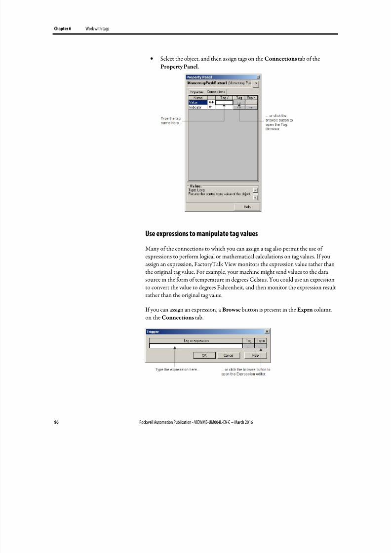
8/17/2019 FactoryTalk® View Machine Edition User's Guide
http://slidepdf.com/reader/full/factorytalk-view-machine-edition-users-guide 96/587
Chapter 6 Work with tags
96 Rockwell Automation Publication - VIEWME-UM004L-EN-E – March 2016
• Select the object, and then assign tags on the Connections tab of theProperty Panel.
Use expressions to manipulate tag values
Many of the connections to which you can assign a tag also permit the use of
expressions to perform logical or mathematical calculations on tag values. If youassign an expression, FactoryTalk View monitors the expression value rather thanthe original tag value. For example, your machine might send values to the datasource in the form of temperature in degrees Celsius. You could use an expressionto convert the value to degrees Fahrenheit, and then monitor the expression resultrather than the original tag value.
If you can assign an expression, a Browse button is present in the Exprn columnon the Connections tab.
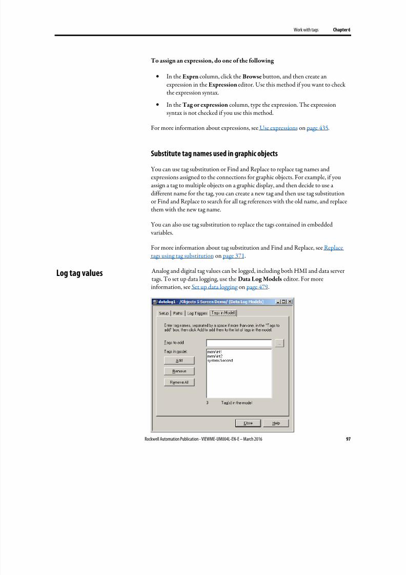
8/17/2019 FactoryTalk® View Machine Edition User's Guide
http://slidepdf.com/reader/full/factorytalk-view-machine-edition-users-guide 97/587
Work with tags Chapter 6
Rockwell Automation Publication - VIEWME-UM004L-EN-E – March 2016 97
To assign an expression, do one of the following
• In the Exprn column, click the Browse button, and then create anexpression in the Expression editor. Use this method if you want to checkthe expression syntax.
• In the Tag or expression column, type the expression. The expressionsyntax is not checked if you use this method.
For more information about expressions, see Use expressions on page 435.
Substitute tag names used in graphic objects
You can use tag substitution or Find and Replace to replace tag names and
expressions assigned to the connections for graphic objects. For example, if youassign a tag to multiple objects on a graphic display, and then decide to use adifferent name for the tag, you can create a new tag and then use tag substitutionor Find and Replace to search for all tag references with the old name, and replacethem with the new tag name.
You can also use tag substitution to replace the tags contained in embedded variables.
For more information about tag substitution and Find and Replace, see Replacetags using tag substitution on page 371.
Analog and digital tag values can be logged, including both HMI and data servertags. To set up data logging, use the Data Log Models editor. For moreinformation, see Set up data logging on page 479.
Log tag values
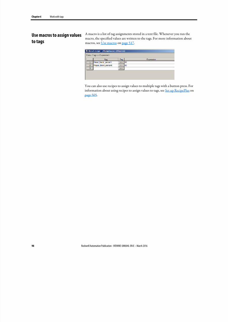
8/17/2019 FactoryTalk® View Machine Edition User's Guide
http://slidepdf.com/reader/full/factorytalk-view-machine-edition-users-guide 98/587
Chapter 6 Work with tags
98 Rockwell Automation Publication - VIEWME-UM004L-EN-E – March 2016
A macro is a list of tag assignments stored in a text file. Whenever you run themacro, the specified values are written to the tags. For more information aboutmacros, see Use macros on page 517.
You can also use recipes to assign values to multiple tags with a button press. Forinformation about using recipes to assign values to tags, see Set up RecipePlus on page 505.
Use macros to assign values
to tags
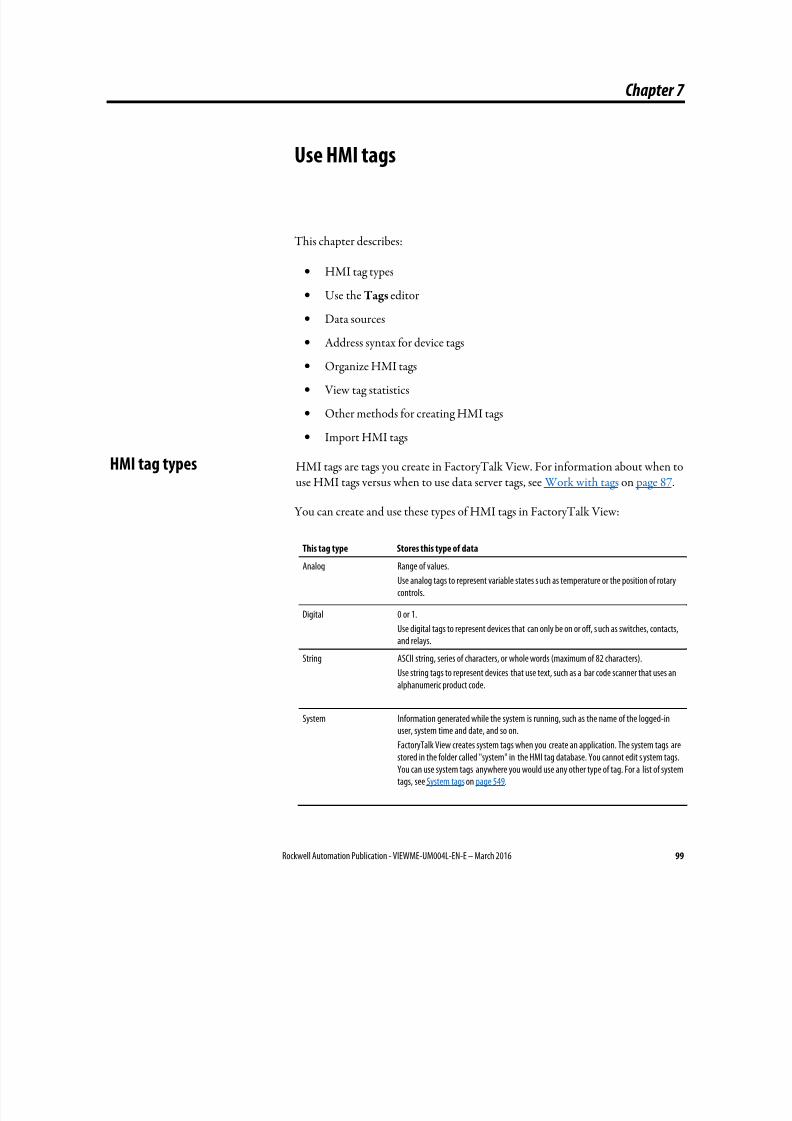
8/17/2019 FactoryTalk® View Machine Edition User's Guide
http://slidepdf.com/reader/full/factorytalk-view-machine-edition-users-guide 99/587
Rockwell Automation Publication - VIEWME-UM004L-EN-E – March 2016 99
Chapter 7
Use HMI tags
This chapter describes:
• HMI tag types
• Use the Tags editor
• Data sources
•
Address syntax for device tags• Organize HMI tags
• View tag statistics
• Other methods for creating HMI tags
• Import HMI tags
HMI tags are tags you create in FactoryTalk View. For information about when touse HMI tags versus when to use data server tags, see Work with tags on page 87.
You can create and use these types of HMI tags in FactoryTalk View:
This tag type Stores this type of data
Analog Range of values.
Use analog tags to represent variable states s uch as temperature or the position of rotarycontrols.
Digital 0 or 1.
Use digital tags to represent devices that can only be on or off, s uch as switches, contacts,and relays.
String ASCII string, series of characters, or whole words (maximum of 82 characters).
Use string tags to represent devices that use text, such as a bar code scanner that uses analphanumeric product code.
System Information generated while the system is running, such as the name of the logged-inuser, system time and date, and so on.
FactoryTalk View creates system tags when you create an application. The system tags arestored in the folder called "system" in the HMI tag database. You cannot edit s ystem tags.You can use system tags anywhere you would use any other type of tag. For a list of systemtags, see System tags on page 549.
HMI tag types
8/17/2019 FactoryTalk® View Machine Edition User's Guide
http://slidepdf.com/reader/full/factorytalk-view-machine-edition-users-guide 100/587
Chapter 7 Use HMI tags
100 Rockwell Automation Publication - VIEWME-UM004L-EN-E – March 2016
Analog tags that use floating-point values
You can assign analog tags to most of the connections in FactoryTalk View,
including both HMI and data server tags. If the analog tag uses a floating-pointdata type but an integer value is required, the floating-point value is rounded.
For information about the data types available for analog tags, see Help.
How values are rounded
When a floating-point value must be rounded to an integer, this is how the value isrounded:
• If the number after the decimal is 4 or less, the value is rounded down. Forexample, 8.495 is rounded to 8.
• If the number after the decimal is 6 or more, the value is rounded up. Forexample, 8.6 is rounded to 9.
• If the number after the decimal is 5, the value is rounded using a "banker’salgorithm," to average out the rounding over time:
• If the number before the decimal is 0, the value is rounded down. Forexample, 10.5 is rounded to 10.
• If the number before the decimal is an odd number, the value isrounded up. For example, 11.5 is rounded to 12.
• If the number before the decimal is an even number, the value isrounded down. For example, 12.5 is rounded to 12.
• Floating point values are rounded to a maximum of six digits.Therefore, using a floating-point data type and adding to it a value thatexceeds the six significant digits will result in a rounding error. Forexample, adding any number to 999,999 will result in a rounding error.
This rounding method is also used for Numeric Input Enable buttons that use theimplicit decimal position, if an integer tag is assigned to the button’s Value
connection. For more information about the Numeric Input Enable button, see
Help.
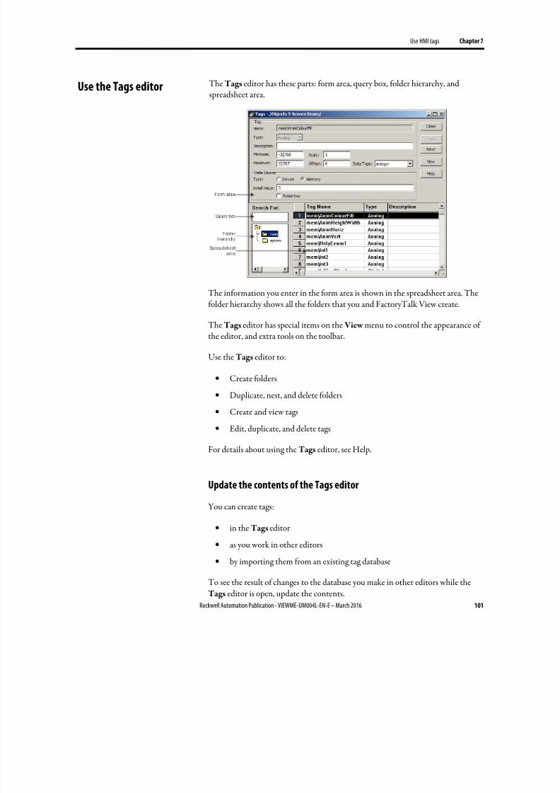
8/17/2019 FactoryTalk® View Machine Edition User's Guide
http://slidepdf.com/reader/full/factorytalk-view-machine-edition-users-guide 101/587
Use HMI tags Chapter 7
Rockwell Automation Publication - VIEWME-UM004L-EN-E – March 2016 101
The Tags editor has these parts: form area, query box, folder hierarchy, andspreadsheet area.
The information you enter in the form area is shown in the spreadsheet area. Thefolder hierarchy shows all the folders that you and FactoryTalk View create.
The Tags editor has special items on the View menu to control the appearance ofthe editor, and extra tools on the toolbar.
Use the Tags editor to:
• Create folders
• Duplicate, nest, and delete folders
• Create and view tags
• Edit, duplicate, and delete tags
For details about using the Tags editor, see Help.
Update the contents of the Tags editor
You can create tags:
• in the Tags editor
• as you work in other editors
• by importing them from an existing tag database
To see the result of changes to the database you make in other editors while theTags editor is open, update the contents.
Use the Tags editor
8/17/2019 FactoryTalk® View Machine Edition User's Guide
http://slidepdf.com/reader/full/factorytalk-view-machine-edition-users-guide 102/587
Chapter 7 Use HMI tags
102 Rockwell Automation Publication - VIEWME-UM004L-EN-E – March 2016
To update the contents of the editor
• From the View menu, select Refresh, or click the Refresh tool.
When you select Refresh, the undo buffer is cleared and recent changescan’t be automatically reversed.
Refresh is not available if you haven’t accepted the current tag.
For information about creating tags in other editors, see Other methods forcreating HMI tags on page 107.
Search for HMI tags
Use the Tags editor’s query box to select the tags you want to show in thespreadsheet. This allows you to edit tags in different folders without browsing thefolder hierarchy. You can:
• Select a single tag by typing the tag name.
• Select multiple tags by typing wildcard characters.
These are the wildcard characters:
This character Does this
? Matches any single character.
* Matches any number of characters, including the backslash (\) character.
Use this wildcard character by itself to show all the tags in the HMI tag database.
For example, to search for all the tags that contain the string "pump" in their name,type *pump* in the Search For box. When you press Enter , a list of tagscontaining the string "pump" appears in the spreadsheet.
When you do searches, remember that the backslash in a folder name counts as acharacter in the tag name.
You can also use Find to search for every occurrence of a specific tag or text stringthroughout different components within FactoryTalk View ME applications.Find also locates all the text strings within each component that refer to the tag.
To find a tag or text string
1. From the Tools menu, select Find, or on the toolbar, click .
2. Type the text string in Find what, or identify the tag to search for:
8/17/2019 FactoryTalk® View Machine Edition User's Guide
http://slidepdf.com/reader/full/factorytalk-view-machine-edition-users-guide 103/587
Use HMI tags Chapter 7
Rockwell Automation Publication - VIEWME-UM004L-EN-E – March 2016 103
• Click the browse button ( ) next to Find what.
• From the Tag Browser , navigate to the correct folder in the left pane,select the tag in the right pane, and click OK to save the selection and
close the browser.
3. If needed, identify the type of product components to search in Find
within (all components are selected by default):
• Click the browse button next to Find within.
• From the Find within dialog box, select the product component typesto be searched and click OK to save the selection and close the dialogbox.
4. Identify the word search limitations in Find Options.
5. Select the Direction in which to search:
• Select Up to search for the tag or text string in all components beforethe open one.
• Select Down to search for the tag or text string in all components afterthe open one.
6. Click Find Next. The location of the found tag or text string is shown inFound item. Click Find Next again to find each item in the search order.You can click the found item to open it in the appropriate editor.
7. If needed, click Find All to view a spreadsheet of all items that match yoursearch criteria. Double click the found item in the spreadsheet to open it.
To find all references to a tag or a text string
1. From the Tools Menu, select Cross Reference, or on the toolbar, click
.
2. Type the text string in Find what, or identify the tag to search for:
• Click the browse button ( ) next to Find what.
• From the Tag Browser , navigate to the correct folder in the left pane,select the tag in the right pane, and click OK to save the selection andclose the browser.
3. If needed, identify the type of product components to search in Find within(all components are selected by default):
8/17/2019 FactoryTalk® View Machine Edition User's Guide
http://slidepdf.com/reader/full/factorytalk-view-machine-edition-users-guide 104/587
Chapter 7 Use HMI tags
104 Rockwell Automation Publication - VIEWME-UM004L-EN-E – March 2016
• Click the browse button next to Find within.
• From the Find within dialog box, select the product component typesto be searched and click OK to save the selection and close the dialog
box.
4. Click Search to show all the found items in a spreadsheet form.
5.
You can double click any of the found items to open it with the appropriateeditor.
When creating an HMI tag, you must specify a data source. The data sourcedetermines whether the tag receives its values externally or internally. For moreinformation about data sources, see The data source on page 88.
Device
A tag with device as its data source receives its data from a source external toFactoryTalk View. The data can come from a programmable controller or otherdevice via RSLinx Enterprise, or from another OPC server. You can use up to5,000 device tags.
For analog tags with Device as the data source, the data type determines the formatused when reading and writing tag data to the data server.
Do not create HMI Tags that are pointing to a System Tag. When a projectcontains an HMI tag pointing to a System Tag, users may fail in creating an MERor have runtime performance issues.
Memory
A tag with memory as its data source receives its data from (and stores values in)the FactoryTalk View internal value table. Tags with memory as the data source donot count toward the total tag limit.
For analog tags with Memory as the data source, select the data type that matches
the format of the data you will store in the tag. Choosing Default is the same aschoosing Floating Point.
For device tags, you must provide the address and path to the OPC server that isconnected to the data source. For example, the OPC server could be connected toa device such as a programmable controller.
The syntax for OPC tag addresses is:
[AccessPath]Address
Data sources
Address syntax for device
tags
8/17/2019 FactoryTalk® View Machine Edition User's Guide
http://slidepdf.com/reader/full/factorytalk-view-machine-edition-users-guide 105/587
Use HMI tags Chapter 7
Rockwell Automation Publication - VIEWME-UM004L-EN-E – March 2016 105
or
::[AccessPath]Address
where :: indicates that the address resides in a data server in the application. Thetwo colons are necessary when the address contains a colon, for example, N7:0.
The square brackets are part of the syntax. They do not indicate optional parameters.
The access path is one of the following:
• For communications with an RSLinx Enterprise data server, the access pathis the name of the device shortcut in RSLinx Enterprise.
• For communications with an RSLinx Classic OPC server, the access path is
the name of an OPC topic in RSLinx Classic.
• For communications with other OPC servers, the access path might beoptional. For information about the syntax for the access path, see yourOPC server documentation.
Example: Logix5000 addressing
We recommend that you use the Tag Browser or Find and Replace to select OPCitems. When you use the Tag Browser the correct syntax and data types are
selected automatically.
However, if you want to define tags before setting up communications, you cantype the address manually, as shown in this example. If you type the addressmanually, be sure to select the data type for the tag that matches the data type usedby the Logix5000 processor. If you use the Default data type, values are treated asfloating-point values.
This example shows you how to specify the OPC topic, item name, and bit level ofan item that uses the integer data type in a Logix5000 processor.
OPC topic and item addressing
Logix5000 uses this addressing syntax:
[ Device shortcut ]item name for RSLinx Enterprise.
[OPC topic name]item name for RSLinx Classic.
In this example, the RSLinx Enterprise device shortcut name for the Logix5000
processor is CLGX . To connect to an OPC item called Motor , type this address:
8/17/2019 FactoryTalk® View Machine Edition User's Guide
http://slidepdf.com/reader/full/factorytalk-view-machine-edition-users-guide 106/587
Chapter 7 Use HMI tags
106 Rockwell Automation Publication - VIEWME-UM004L-EN-E – March 2016
[CLGX]Motor
Bit level addressing
You can gain access to the bit level of an item that uses the integer data type byappending .# to the end of the tag address, where # is the number of the bit you want access to.
For example, to gain access to the first bit of the integer item Motor , type this
address:
[CLGX]Motor.0
Organized tags makes finding and using tags faster and simpler. To organize yourtags, try these tips:
•
Establish naming conventions.
Naming conventions enable you to use wildcard characters most effectively
when searching for and showing tags during development.
• Use folders to group related tags.
Name tags
A tag name can be up to 255 characters long including folder name. If you create a
folder, the folder name becomes part of the tag name. The backslash (\) after afolder name counts as a character.
A tag name can contain these characters:
• A to Z
• 0 to 9
• underscore (_) and dash (-)
A tag name cannot contain spaces.
A tag name can be mixed case. A tag name preserves upper and lower cases forreadability but is not case sensitive. For example, the tag name MixerValve1 is the
same as mixervalve1.
When a tag name starts with a number or contains a dash, enclose the name incurly brackets { } when you use it in an expression, for example, {N33-0}. For moreinformation about using tags in expressions, see Use expressions on page 435.
Organize HMI tags
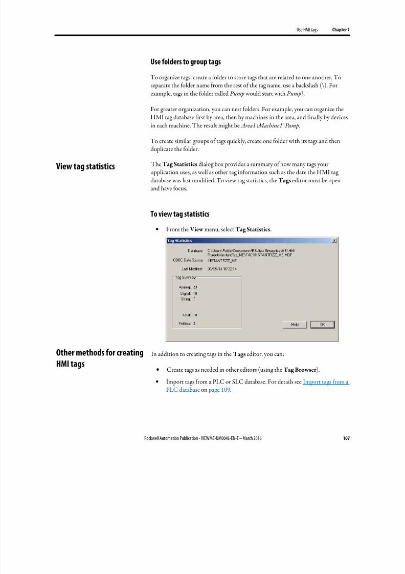
8/17/2019 FactoryTalk® View Machine Edition User's Guide
http://slidepdf.com/reader/full/factorytalk-view-machine-edition-users-guide 107/587
Use HMI tags Chapter 7
Rockwell Automation Publication - VIEWME-UM004L-EN-E – March 2016 107
Use folders to group tags
To organize tags, create a folder to store tags that are related to one another. To
separate the folder name from the rest of the tag name, use a backslash (\). Forexample, tags in the folder called Pump would start with Pump\.
For greater organization, you can nest folders. For example, you can organize theHMI tag database first by area, then by machines in the area, and finally by devicesin each machine. The result might be Area1\Machine1\Pump.
To create similar groups of tags quickly, create one folder with its tags and thenduplicate the folder.
The Tag Statistics dialog box provides a summary of how many tags yourapplication uses, as well as other tag information such as the date the HMI tag
database was last modified. To view tag statistics, the Tags editor must be openand have focus.
To view tag statistics
• From the View menu, select Tag Statistics.
In addition to creating tags in the Tags editor, you can:
• Create tags as needed in other editors (using the Tag Browser ).
• Import tags from a PLC or SLC database. For details see Import tags from aPLC database on page 109.
View tag statistics
Other methods for creatingHMI tags
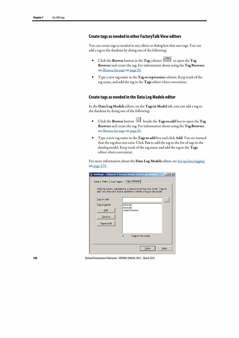
8/17/2019 FactoryTalk® View Machine Edition User's Guide
http://slidepdf.com/reader/full/factorytalk-view-machine-edition-users-guide 108/587
Chapter 7 Use HMI tags
108 Rockwell Automation Publication - VIEWME-UM004L-EN-E – March 2016
Create tags as needed in other FactoryTalk View editors
You can create tags as needed in any editor or dialog box that uses tags. You can
add a tag to the database by doing one of the following:
• Click the Browse button in the Tag column to open the Tag
Browser and create the tag. For information about using the Tag Browser ,see Browse for tags on page 91.
• Type a new tag name in the Tag or expression column. Keep track of thetag name, and add the tag in the Tags editor when convenient.
Create tags as needed in the Data Log Models editor
In the Data Log Models editor, on the Tags in Model tab, you can add a tag tothe database by doing one of the following:
• Click the Browse button beside the Tags to add box to open the Tag
Browser and create the tag. For information about using the Tag Browser ,see Browse for tags on page 91.
• Type a new tag name in the Tags to add box and click Add. You are warnedthat the tag does not exist. Click Yes to add the tag to the list of tags in thedatalog model. Keep track of the tag name and add the tag in the Tags editor when convenient.
For more information about the Data Log Models editor, see Set up data logging on page 479.

8/17/2019 FactoryTalk® View Machine Edition User's Guide
http://slidepdf.com/reader/full/factorytalk-view-machine-edition-users-guide 109/587
Use HMI tags Chapter 7
Rockwell Automation Publication - VIEWME-UM004L-EN-E – March 2016 109
Use the Import PLC Tags dialog box to selectively import tags from a PLC orother database into your application’s HMI tag database. Tags imported in this way are copied into the database. They are not shared with the source database.This means changes to tags in your application do not affect the database from
which they have been imported, and vice versa.
You can import tags from any of these databases:
• RSLogix 500 internal database, with file extension .rss
• RSLogix 5 internal database, with file extension .rsp
• RSLogix 5 or RSLogix 500, saved as an external database, with file extension.ctd (before importing, explicitly export to the .ctd format to be sure ofincluding the latest changes)
For PLC and SLC addresses, the Import PLC Tags dialog box shows onlyaddresses that are used in the symbol or address list of the PLC programmingsoftware.
To open the Import PLC Tags dialog box, do one of the following
• In the Tag Browser , right-click the right pane and select Import PLC
Tags. For information about using the Tag Browser , see Browse for tags on page 91.
•
In the Tags editor, from the Edit menu select Other Databases, or clickthe DB Browser tool .
Import tags from a PLC
database

8/17/2019 FactoryTalk® View Machine Edition User's Guide
http://slidepdf.com/reader/full/factorytalk-view-machine-edition-users-guide 110/587
Chapter 7 Use HMI tags
110 Rockwell Automation Publication - VIEWME-UM004L-EN-E – March 2016
For more information about using the Import PLC Tags dialog box, see Help.
You can also import PLC or SLC databases into FactoryTalk View using the TagImport and Export Wizard.
You can use the wizard to:
• Export your application’s tags to a .csv file.
• Import tags from another FactoryTalk View application’s tag .csv file.
• Merge tags from another FactoryTalk View application (that is, importthem directly from the application, without first creating a tag .csv file).
• Import tags from RSLogix 5 or RSLogix 500, saved as an external database, with file extension .ctd (before importing, explicitly export to the .ctd
format to be sure of including the latest changes).
To start the wizard, do one of the following
• In FactoryTalk View Studio, from the Tools menu, select Tag Import and
Export Wizard.
• From Windows Start menu, select Programs > Rockwell Software>
FactoryTalk View> Tools> Tag Import and Export Wizard.
For details about using the wizard, see the Tag Import and Export Wizard Help.
Use the Tag Import and
Export Wizard

8/17/2019 FactoryTalk® View Machine Edition User's Guide
http://slidepdf.com/reader/full/factorytalk-view-machine-edition-users-guide 111/587
Rockwell Automation Publication - VIEWME-UM004L-EN-E – March 2016 111
Chapter 8
Set up global connections
This chapter describes:
• What global connections are
• Update the date and time
• Change displays
•
Control display changes remotely• Use parameter files or parameter lists with display changes
• Close On Top displays
• Print displays
• Run macros
• Set up the backlight intensity remotely
• Monitor runtime RAM usage
Global connections are connections that apply to your entire runtime application.Global connections allow the data source to control or interact with yourapplication at runtime.
You can use global connections to:
• Update the date and time at the data source using the runtime terminal’sdate and time.
• Update the date and time on the runtime terminal using the data sourcedate and time.
• Notify the data source of the current display number.
• Notify the data source when a display is printed.
• Change the display on the runtime terminal remotely (from the datasource).
• Close On Top displays
• Apply parameter files or parameter lists to the tag placeholders in thechanged displays.
• Print the current display from the data source.
About global connections
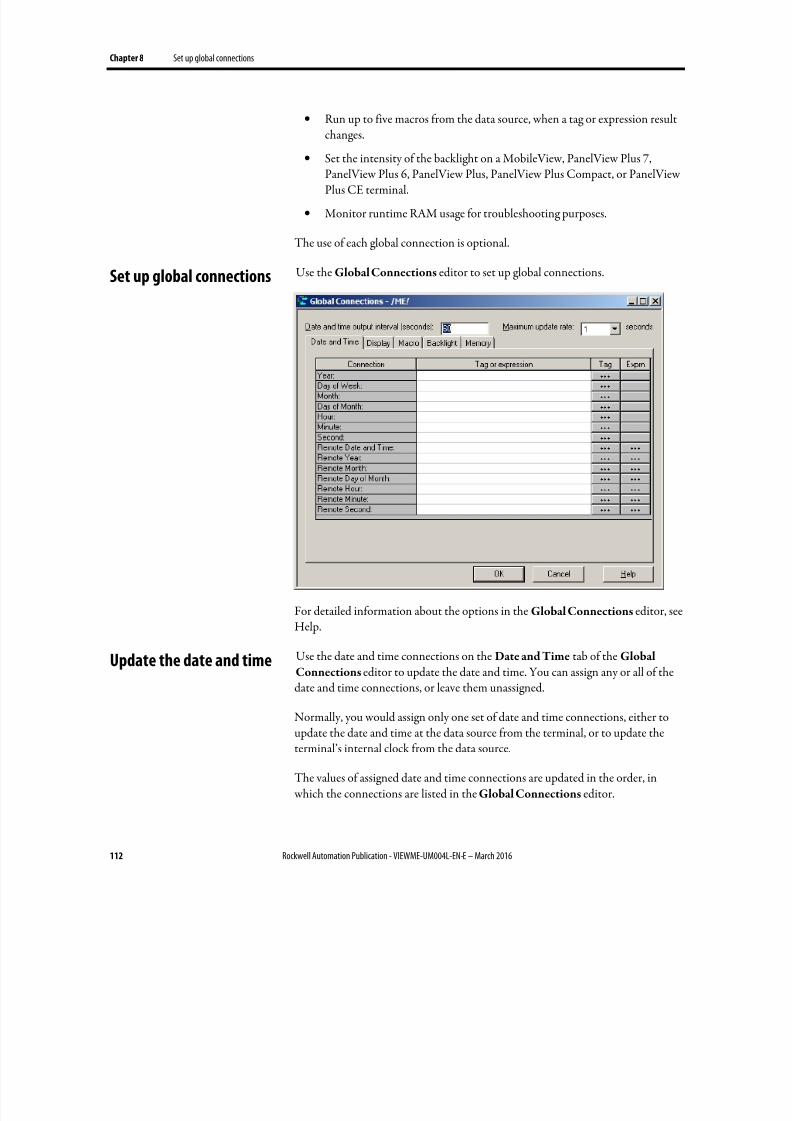
8/17/2019 FactoryTalk® View Machine Edition User's Guide
http://slidepdf.com/reader/full/factorytalk-view-machine-edition-users-guide 112/587
Chapter 8 Set up global connections
112 Rockwell Automation Publication - VIEWME-UM004L-EN-E – March 2016
• Run up to five macros from the data source, when a tag or expression resultchanges.
• Set the intensity of the backlight on a MobileView, PanelView Plus 7,
PanelView Plus 6, PanelView Plus, PanelView Plus Compact, or PanelViewPlus CE terminal.
• Monitor runtime RAM usage for troubleshooting purposes.
The use of each global connection is optional.
Use the Global Connections editor to set up global connections.
For detailed information about the options in the Global Connections editor, seeHelp.
Use the date and time connections on the Date and Time tab of the Global
Connections editor to update the date and time. You can assign any or all of thedate and time connections, or leave them unassigned.
Normally, you would assign only one set of date and time connections, either toupdate the date and time at the data source from the terminal, or to update theterminal’s internal clock from the data source.
The values of assigned date and time connections are updated in the order, in which the connections are listed in the Global Connections editor.
Set up global connections
Update the date and time

8/17/2019 FactoryTalk® View Machine Edition User's Guide
http://slidepdf.com/reader/full/factorytalk-view-machine-edition-users-guide 113/587
Set up global connections Chapter 8
Rockwell Automation Publication - VIEWME-UM004L-EN-E – March 2016 113
Update the date and time at the data source from the terminal
To update the date or time at the data source from the terminal’s internal clock,
assign a tag to one or more of these connections:
This connection Contains this range of values
Year 00-99
Day of Week 1-7, with 1 being Sunday
Month 1-12
Day of Month 1-31
Hour 0-23
Minute 0-59
Second 0-59
Specify how frequently to update the values of the assigned connections at the datasource (from the terminal’s internal clock) by typing a time in the Date and timeoutput interval box.
Update the date and time at the terminal from the data source
This option is especially useful if you have several terminals connected to the samedata source. Instead of the operator resetting the date and time manually on eachterminal, the data source can reset all internal clocks at once.
To update the date or time in the terminal’s internal clock from the data source,assign a tag or an expression to the Remote Date and Time connection. Also assigna tag or an expression to one or more of these connections:
This connection Contains this range of values
Remote Year 00-99 or 0000-9999
Remote Month 1-12
Remote Day of Month 1-31
Remote Hour 0-23
Remote Minute 0-59
Remote Second 0-59
When the Remote Date and Time connection value changes to a new non-zero value, the terminal resets its internal time and date to the time and date read fromthe individual remote date and time connections.
The date and time are updated at the rate specified in the Maximum update rate box, but changes are not made until the Remote Date and Time connectionchanges to a new non-zero value.
8/17/2019 FactoryTalk® View Machine Edition User's Guide
http://slidepdf.com/reader/full/factorytalk-view-machine-edition-users-guide 114/587
Chapter 8 Set up global connections
114 Rockwell Automation Publication - VIEWME-UM004L-EN-E – March 2016
Use these global connections on the Display tab of the Global Connections editor to monitor and control display changes:
• Replace Display Number — notifies the data source of the number of theReplace display that’s currently open.
• Remote Display Number — allows the data source to change the display on the runtime computer.
Control display changes remotely
To control display changes remotely, you can set up the data source to opengraphic displays using global connections.
For example, the Remote Display Number connection is a global connection that you can use to control display changes from the data source.
For more information, see About global connections on page 111.
Remote display changes and security
If you set up the data source to open graphic displays remotely, remote displaychanges occur whether the logged-in user has security access to a given display.
Set up remote display changes
This section outlines the steps for setting up remote display changes. For moredetailed information about the Global Connections editor, see Help.
To set up remote display changes
1. In the Graphics editor, in the Display Settings dialog box, every new display is assigned the number 1 by default. Therefore, to use remote display changes, you must assign a unique display number to each Replace and On
Top display that you want to change remotely.
For more information about graphic displays, see Use graphic displays on
page 303.
2. In the Global Connections editor, assign a tag or an expression to theRemote Display Number connection.
Change displays
8/17/2019 FactoryTalk® View Machine Edition User's Guide
http://slidepdf.com/reader/full/factorytalk-view-machine-edition-users-guide 115/587
Set up global connections Chapter 8
Rockwell Automation Publication - VIEWME-UM004L-EN-E – March 2016 115
3. If you assign a tag to the Remote Display Number connection, set up thedata source to send a display’s number to the connection when you want thedisplay to open.
4.
If you assign an expression to the Remote Display Number connection,FactoryTalk View monitors the values of the tags used in the expression,and uses the expression result to determine which display to open.
5. If you assign a tag to the Close An On Top Display or Close all On Top
Displays connection, or both, set up the data source to send a display’snumber to the connection when you want one or more displays to close.
6. If you assign an expression to the Close An On Top Display or Close all
On Top Displays connection, FactoryTalk View monitors the values of thetags used in the expression, and uses the expression result to determine
which display to close.
Use these global connections on the Display tab of the Global Connections editor to monitor and control display printing:
• Display Print Active — notifies the data source that a display print is in progress.
• Remote Display Print — allows the data source to trigger a display print.
The operator can also print the current display by pressing the display printbutton. For information about setting up this button, see Help.
When the data source or the operator prints a display, everything on the screen is printed, including the current display, pop-up windows, and any visiblebackground applications.
If you plan to print graphic displays remotely, turn off the screen saver. If thescreen saver is on when a remote display print is triggered, only the screen saverimage is printed.
For information abut turning off the screen saver on personal computers, see your Windows documentation.
For information about turning off the screen saver on a MobileView, PanelViewPlus 7, PanelView Plus 6, PanelView Plus, PanelView Plus Compact, or PanelView
Plus CE terminal, see the terminal's User Manual .
Use these global connections to close displays remotely:
• Close an On Top display — notifies the data source of the number of theOn Top display to be closed.
Print displays
Close On Top displays
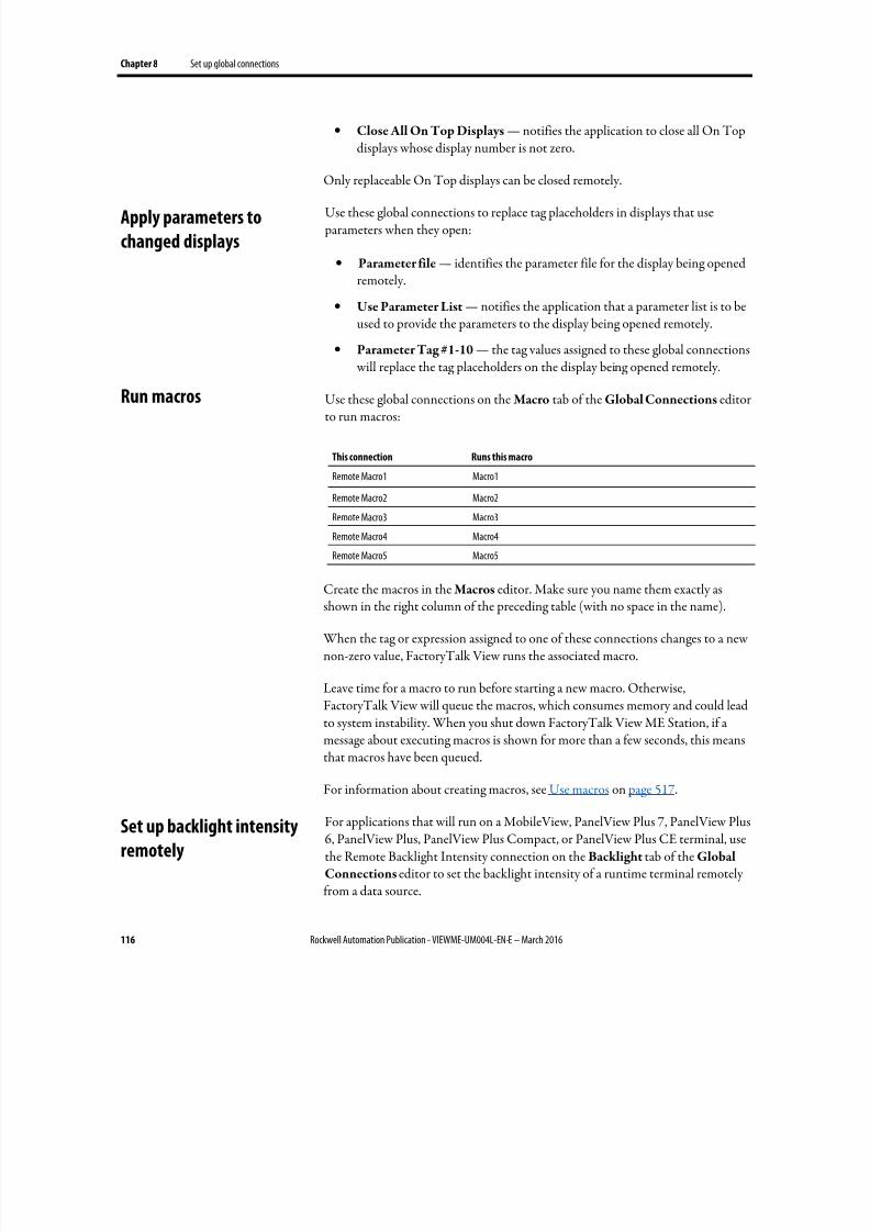
8/17/2019 FactoryTalk® View Machine Edition User's Guide
http://slidepdf.com/reader/full/factorytalk-view-machine-edition-users-guide 116/587
Chapter 8 Set up global connections
116 Rockwell Automation Publication - VIEWME-UM004L-EN-E – March 2016
• Close All On Top Displays — notifies the application to close all On Topdisplays whose display number is not zero.
Only replaceable On Top displays can be closed remotely.
Use these global connections to replace tag placeholders in displays that use parameters when they open:
• Parameter file — identifies the parameter file for the display being openedremotely.
• Use Parameter List — notifies the application that a parameter list is to beused to provide the parameters to the display being opened remotely.
• Parameter Tag #1-10 — the tag values assigned to these global connections will replace the tag placeholders on the display being opened remotely.
Use these global connections on the Macro tab of the Global Connections editorto run macros:
This connection Runs this macro
Remote Macro1 Macro1
Remote Macro2 Macro2
Remote Macro3 Macro3
Remote Macro4 Macro4
Remote Macro5 Macro5
Create the macros in the Macros editor. Make sure you name them exactly asshown in the right column of the preceding table (with no space in the name).
When the tag or expression assigned to one of these connections changes to a newnon-zero value, FactoryTalk View runs the associated macro.
Leave time for a macro to run before starting a new macro. Otherwise,FactoryTalk View will queue the macros, which consumes memory and could leadto system instability. When you shut down FactoryTalk View ME Station, if amessage about executing macros is shown for more than a few seconds, this means
that macros have been queued.
For information about creating macros, see Use macros on page 517.
For applications that will run on a MobileView, PanelView Plus 7, PanelView Plus6, PanelView Plus, PanelView Plus Compact, or PanelView Plus CE terminal, usethe Remote Backlight Intensity connection on the Backlight tab of the GlobalConnections editor to set the backlight intensity of a runtime terminal remotelyfrom a data source.
Apply parameters to
changed displays
Run macros
Set up backlight intensity
remotely
8/17/2019 FactoryTalk® View Machine Edition User's Guide
http://slidepdf.com/reader/full/factorytalk-view-machine-edition-users-guide 117/587
Set up global connections Chapter 8
Rockwell Automation Publication - VIEWME-UM004L-EN-E – March 2016 117
To update the backlight intensity of the runtime terminal from the data source,assign a tag or an expression to this read-only connection.
This connection Contains this range of valuesRemote Backlight Intensity 0-100
At runtime, the application reads the value at the data source and sets thebacklight to the percentage of its maximum intensity corresponding to the value.For instance, if the value of the connection is 25, the backlight will be set to 25 percent of its maximum intensity. This value will override the terminal’s ownbacklight intensity setting.
If the value of the connection is greater than 100, the backlight will be set to itsmaximum intensity. If the value is less than 0, the backlight is set to its minimum
intensity. That is, it will be turned off.
Sometimes it is helpful to monitor runtime RAM usage for troubleshooting purposes. If your application seems to be running slowly, consuming too muchmemory, or interfering with the operation of other applications on the same personal computer or terminal, it is useful to monitor the exact amount ofmemory the applications are consuming.
Tip: • To reduce runtime RAM usage, reduce the number of displays or tags in yourapplication, and restart the application regularly (for example, once a week).Adding more RAM to the terminal will not help. For m ore information, seeAnswer ID 39481 in Rockwell Automation Knowledgebase.
•
The PanelView Plus, PanelView Plus Compact, and PanelView Plus CEterminals’ operating systems have a 32 MB RAM process limit. On theseterminals, FactoryTalk View ME Station has a tag connection threshold of 26MB. Screen change performance will slow down significantly as the systemadds and removes tag connections from the c ache.
Use these global connections on the Memory tab of the Global Connections editor to monitor runtime RAM usage:
This connection Provides this information, in kilobytes (Kb)
ME Runtime RAM Usage The amount of memory being used by your application (and by theMERuntime.exe process)
Total RAM Usage The total amount of memory being used by all applications (and processes ) onthe personal computer or terminal
Available RAM The remaining amount of memory available
Remote RAM Usage Assign a tag or expression to this connection. When it has a non-zero value, datais sent to the other three connections, if assigned.
You can monitor the values of the MERuntime RAM Usage, Total RAM Usage,and Available RAM connections using data logging or using graphic objects suchas numeric displays. The connections are updated every ten seconds as long as theRemote RAM Usage connection has a non-zero value. Set up the data source to
Monitor runtime RAM usage

8/17/2019 FactoryTalk® View Machine Edition User's Guide
http://slidepdf.com/reader/full/factorytalk-view-machine-edition-users-guide 118/587
Chapter 8 Set up global connections
118 Rockwell Automation Publication - VIEWME-UM004L-EN-E – March 2016
set this connection to a non-zero value when you want memory monitoring tooccur, or assign the same tag or expression to a graphic object such as aMaintained push button that the operator can use to turn memory monitoring onand off.
These connections are available when you run FactoryTalk View ME Station on a personal computer and on the MobileView, PanelView Plus 7, PanelView Plus 6,PanelView Plus, PanelView Plus Compact, and PanelView Plus CE terminals.
For PanelView Plus 7, PanelView Plus 6, PanelView Plus, PanelView PlusCompact, and PanelView Plus CE terminals, you can also turn on the display ofRAM usage statistics at runtime. To do this, in the Configuration Mode window,select Runtime RAM Usage, and then make your selections in the Runtime
RAM Usage window. For more information, see the terminals' User Manual .
8/17/2019 FactoryTalk® View Machine Edition User's Guide
http://slidepdf.com/reader/full/factorytalk-view-machine-edition-users-guide 119/587
Rockwell Automation Publication - VIEWME-UM004L-EN-E – March 2016 119
Chapter 9
Set up alarms
This chapter describes:
• Steps for setting up alarms
• Prepare to set up alarms
• How alarms work
•
Alarm trigger data types• Tips for using array tags
• Optional alarm connections.
• Create alarm messages in multiple languages
• The [ALARM], [ALARM BANNER], [ALARM MULTI-LINE],[STATUS], and [HISTORY] displays
• Use displays from the library in your application
• Create your own alarm display
•
Open and close the alarm display
• How the alarm list, alarm banner, and alarm status list graphic objects work
• Use buttons to acknowledge, silence, clear, and delete alarms
• Use buttons to sort alarms and reset alarm status
An alarm occurs when something goes wrong or is about to go wrong. Alarms cansignal that a device or process has ceased operating within acceptable, predefinedlimits, and can indicate breakdown, wear, or process malfunctions. Alarms are alsoused to indicate the approach of a dangerous condition.
Alarms are an important part of most plant control applications because anoperator must know the instant something goes wrong. It is often equallyimportant to have a record of the alarm and whether the alarm was acknowledged.
PanelView Plus 7 Standard applications and Compact Machine Editionapplications (applications running on PanelView Plus 6 Compact or PanelViewPlus Compact terminals) have a limit of 200 alarm messages.
About alarms
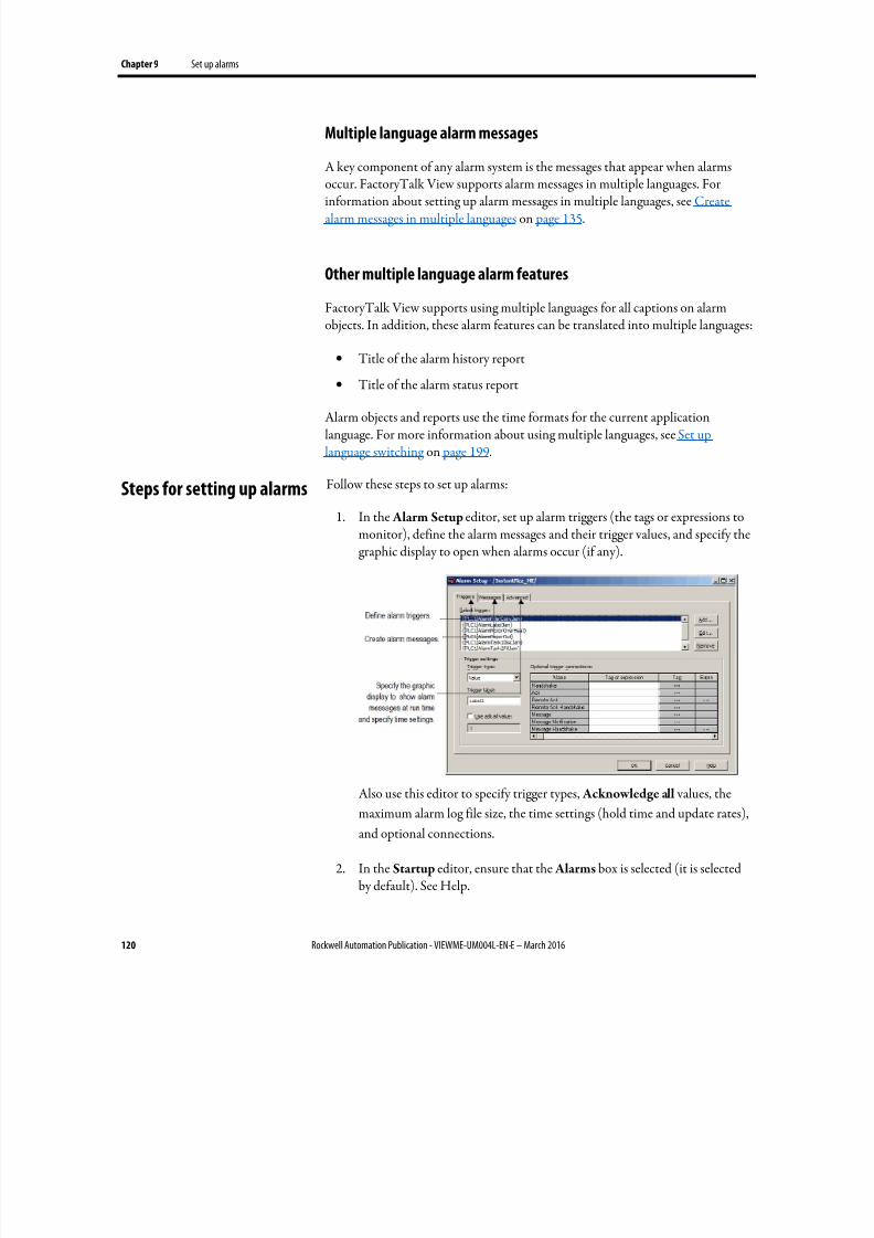
8/17/2019 FactoryTalk® View Machine Edition User's Guide
http://slidepdf.com/reader/full/factorytalk-view-machine-edition-users-guide 120/587
Chapter 9 Set up alarms
120 Rockwell Automation Publication - VIEWME-UM004L-EN-E – March 2016
Multiple language alarm messages
A key component of any alarm system is the messages that appear when alarms
occur. FactoryTalk View supports alarm messages in multiple languages. Forinformation about setting up alarm messages in multiple languages, see Createalarm messages in multiple languages on page 135.
Other multiple language alarm features
FactoryTalk View supports using multiple languages for all captions on alarmobjects. In addition, these alarm features can be translated into multiple languages:
• Title of the alarm history report
•
Title of the alarm status report
Alarm objects and reports use the time formats for the current applicationlanguage. For more information about using multiple languages, see Set uplanguage switching on page 199.
Follow these steps to set up alarms:
1.
In the Alarm Setup editor, set up alarm triggers (the tags or expressions tomonitor), define the alarm messages and their trigger values, and specify thegraphic display to open when alarms occur (if any).
Also use this editor to specify trigger types, Acknowledge all values, the
maximum alarm log file size, the time settings (hold time and update rates),
and optional connections.
2. In the Startup editor, ensure that the Alarms box is selected (it is selectedby default). See Help.
Steps for setting up alarms
8/17/2019 FactoryTalk® View Machine Edition User's Guide
http://slidepdf.com/reader/full/factorytalk-view-machine-edition-users-guide 121/587
Set up alarms Chapter 9
Rockwell Automation Publication - VIEWME-UM004L-EN-E – March 2016 121
3. If desired, in the Graphics editor, modify the default [ALARM] display, orcreate your own graphic display to use for alarms. For example, if you won’tbe using audible alarm signals, edit the default display to remove the silencealarms button.
For information about graphic displays, see Use graphic displays on page
303.
4. Test alarms on the runtime system.
As your application is running, information is continually sent to the data sourceabout the state of the various processes. For example, your application might bemonitoring whether a valve is open or closed, or the temperature in a boiler. Values representing the status of these processes are sent to the data source. Formore information about data sources, see The data source on page 88.
The first step in setting up alarms is determining which processes to monitor foralarm conditions.
Tags and expressions
Before setting up alarms, you must set up data server or HMI tags correspondingto the addresses at the data source that will store the values you want to monitorfor alarm conditions. You can monitor analog and digital tags for alarmconditions, including both HMI and data server tags. You cannot monitor string
tags.
For information about setting up data server tags, see your OPC data serverdocumentation. For information about creating HMI tags, see Use HMI tags on page 99.
You can also use expressions to perform logical or mathematical calculations ontag values, and then monitor the expression value rather than the original tag value. For example, you could use an expression to monitor whether a tag value hasincreased or decreased beyond a threshold value: If Tag1 > 90 then 1 else 2.
For information about creating expressions, see Use expressions on page 435.
Identify alarm conditions
Once you have identified the processes you want to monitor for alarms, and thetags or expressions that will store the values representing the status of the processes, you must determine the acceptable range of values for each tag orexpression. Then you can set up alarms to notify the operator when a value isoutside the normal operating range.
Prepare to set up alarms
8/17/2019 FactoryTalk® View Machine Edition User's Guide
http://slidepdf.com/reader/full/factorytalk-view-machine-edition-users-guide 122/587
Chapter 9 Set up alarms
122 Rockwell Automation Publication - VIEWME-UM004L-EN-E – March 2016
Import and export alarm setup files
The Alarm Import Export Wizard in FactoryTalk View Studio allows you to
export alarm information to an XML file, and to import an alarm setup XML file.
For example, you can export an application’s alarm setup information, import thesetup to another FactoryTalk View application, and then modify it in the newapplication to suit your requirements. Or, you can modify the file beforeimporting it to the new application.
You can use the Alarm Import Export Wizard to import alarm setup informationthat has been created using an external programming tool or editor, or you canimport a FactoryTalk View XML file.
For more information about importing and exporting alarm setup files, see Import
and export alarm XML files on page 553.
This section provides an overview of the key components of your application’salarm system, and describes how the different parts work together.
Alarm triggers and trigger values
You specify the tags and expressions (also known as connections) to monitor foralarm conditions by creating an alarm trigger for each connection.
Each alarm trigger can generate one or more alarm messages, associated withdifferent trigger connection values. For each alarm trigger, you specify the trigger values that will generate alarm messages, and create the messages to show for thetrigger values.
The trigger value can be a non-zero integer value or a bit position, depending on which trigger data type you assign. For more information about trigger data types,see Alarm trigger data type on page 129.
An alarm’s Trigger and Remote Ack settings should not be configured to use thesame tag. Doing so may cause unpredictable alarm acknowledgement behaviors.
Filter alarm triggers in multiple languages
FactoryTalk View 5.00 and later supports alarm triggers in multiple languages. When you create an alarm trigger, its name is in the current application language.You can export alarm triggers for translation and then import them back to theapplication. For details, see Set up language switching on page 199.
How alarms work
8/17/2019 FactoryTalk® View Machine Edition User's Guide
http://slidepdf.com/reader/full/factorytalk-view-machine-edition-users-guide 123/587
Set up alarms Chapter 9
Rockwell Automation Publication - VIEWME-UM004L-EN-E – March 2016 123
Various graphic objects allow you to specify the alarm triggers, to which theobject’s action applies, using the name of the alarm trigger. This is called filteringalarms. When you translate trigger names into other languages, the defaultlanguage is used to show the trigger name in the object’s selection list. Thesegraphic objects allow you to specify alarm triggers using a selection list called theTrigger Label Selector:
• Alarm list
• Alarm status list
• Alarm banner
• Clear alarm history button
• Acknowledge all alarms button
•
Print alarm history button• Print alarm status button
If the trigger label name has not been set up in the default language, the TriggerLabel Selector shows a question mark (?) instead of the trigger label name. Tocorrect the display, you must import the trigger labels for the default language.
You can also manually type in the trigger label names to use to filter alarms. If youmanually type in the trigger names, specify the names in the default language.
If you change the default language, you must re-specify the trigger labels for each of
the graphic objects listed above, using the trigger label names in the new defaultlanguage. For more information about the default language, see The defaultlanguage on page 200.
Alarm notification methods
You can use any combination of these methods to notify the operator that analarm condition has occurred:
• Open an alarm graphic display containing an appropriate alarm message.
•
Set off an audible signal (if the application is running on a personalcomputer).
• Send a message to a printer.
• Send a message to the data source.
If you set up alarm messages in multiple languages, make sure that the data sourcecan either receive the message in Unicode format or convert it into ASCIIcharacters for all the languages you will be using.
8/17/2019 FactoryTalk® View Machine Edition User's Guide
http://slidepdf.com/reader/full/factorytalk-view-machine-edition-users-guide 124/587
Chapter 9 Set up alarms
124 Rockwell Automation Publication - VIEWME-UM004L-EN-E – March 2016
To use these methods, select the Display , Audio, Print, and Message to Tag options when you create your messages.
If you need to keep a permanent record of alarms, be sure to select the Print
option. You can also print the contents of the alarm log file periodically, asdescribed on Methods for printing alarm information on page 127.
Show alarm information
FactoryTalk View comes with these alarm displays:
• [ALARM], in the Displays folder, contains an alarm banner graphic objectthat is set up to show the newest active alarm in the alarm log file.
•
[ALARM BANNER], a display in the Libraries folder, contains an alarmbanner graphic object that is set up to show the newest active alarm in thealarm log file.
• [ALARM MULTI-LINE], a display in the Libraries folder, contains analarm list graphic object that is set up to show all the alarms in the alarm logfile: active, inactive, acknowledged, and unacknowledged.
• [STATUS], a display in the Libraries folder, contains an alarm status listgraphic object that is set up to show active alarms. It contains a Goto displaybutton for opening the [HISTORY] display. This display is available in twosizes.
•
[HISTORY], a display in the Libraries folder, contains an alarm listgraphic object and a Goto display button for opening the [STATUS]display. The alarm list is set up to show all the alarms in the alarm log file:active, inactive, acknowledged, and unacknowledged. This display isavailable in two sizes.
By default, the [ALARM] graphic display opens automatically at runtime when analarm is generated.
You can accept the default, edit the [ALARM] display, use one of the other alarmdisplays, or create your own display. If you select not to automatically open a
graphic display for alarm notification, an alternative is to provide the operator with a way to open an alarm display when desired.
For more information, see:
• The [ALARM] display on page 144
• The [ALARM BANNER] display on page 145
• The [ALARM MULTI-LINE] display on page 145
• The [STATUS] display on page 146
8/17/2019 FactoryTalk® View Machine Edition User's Guide
http://slidepdf.com/reader/full/factorytalk-view-machine-edition-users-guide 125/587
Set up alarms Chapter 9
Rockwell Automation Publication - VIEWME-UM004L-EN-E – March 2016 125
• The [HISTORY] display on page 147
• Create your own alarm display on page 149
• The alarm list graphic object on page 150
• The alarm banner graphic object on page 152
• The alarm status list graphic object on page 152
Interact with alarms
Depending on which alarm objects you set up, the operator can:
• Acknowledge one or all alarms, or the alarms for a specific alarm trigger
•
Clear and delete alarms
• Silence alarms (if the application is running on a personal computer)
• Sort alarms
• Reset the status of all alarms
• Print alarms
For information about the alarm button graphic objects the operator can use to work with alarms, see Use buttons with the alarm history and alarm objects on page 154.
Use the data source to interact with alarms
You can also set up remote acknowledgement, silencing, and resetting of alarms, toallow the data source to perform these functions. And you can set up the datasource to determine which types of alarms to show (active, inactive, acknowledged,and unacknowledged), and to close the alarm display. These topics are discussedlater in the chapter.
Methods for acknowledging alarms
A single alarm is acknowledged when:
• The operator selects an alarm in the alarm list and presses the acknowledgealarm button, an enter button object, or the Enter key on an externalkeyboard or keypad.
• The alarm banner has focus and the operator presses the acknowledge alarmbutton.
A single alarm for a particular trigger is acknowledged when:
8/17/2019 FactoryTalk® View Machine Edition User's Guide
http://slidepdf.com/reader/full/factorytalk-view-machine-edition-users-guide 126/587
Chapter 9 Set up alarms
126 Rockwell Automation Publication - VIEWME-UM004L-EN-E – March 2016
• The trigger’s Remote Ack connection value changes to the alarm’s trigger value (or bit position, for bit triggers).
All alarms for a particular trigger are acknowledged when:
• The trigger’s Remote Ack connection value changes to the Acknowledge
all value. The Acknowledge all value is specified in the Use ack all value box in the Alarm Setup editor.
• The operator presses an acknowledge all alarms button that is set up toacknowledge the alarms for a specific alarm trigger.
All alarms in the alarm log file are acknowledged when:
• The operator presses an acknowledge all alarms button that is set up to
acknowledge all alarms.• The Remote Ack All connection value changes to a new non-zero value.
For more information about acknowledging alarms, see Use alarm buttons toacknowledge, silence, clear, and delete alarms on page 156.
Tip: The operator can send button presses to objects that do not have focus. For informationabout linking buttons to objects, see Link buttons to objects on page 408.
Methods for clearing and deleting alarms
Alarms are deleted from the alarm log file and cleared from all alarm lists andalarm banners when the operator presses the clear alarm history button. You canset up the button to clear alarms for all alarms, or for a specific alarm trigger.
The alarm in the alarm banner is cleared when the operator presses the clear alarmbanner button. It is not deleted from the alarm log file.
For more information about clearing and deleting alarms, see Create and deletemessages on page 157.
Methods for silencing alarms
The audio alarm indicator is available for applications running on personalcomputers and MobileView terminals only.
All alarms are silenced when:
• The operator presses the silence alarms button.
• An alarm whose Audio property is turned on is acknowledged.
8/17/2019 FactoryTalk® View Machine Edition User's Guide
http://slidepdf.com/reader/full/factorytalk-view-machine-edition-users-guide 127/587
Set up alarms Chapter 9
Rockwell Automation Publication - VIEWME-UM004L-EN-E – March 2016 127
• The Remote Silence connection value changes to a new non-zero value.
• The operator presses the clear alarm history button.
Method for sorting alarms
When the operator presses the sort alarms button, the sort order toggles from timeto trigger value or from trigger value to time. The sort order applies to all alarms inall alarm lists and in the alarm log file.
Methods for resetting alarms
Resetting alarms affects how alarms are shown in the alarm status list. Whenalarms are reset:
•
The accumulated time an alarm has been in alarm is reset to 0. If the alarmis still active, the time begins accumulating again.
• The number of times the alarm has been triggered is reset to 0. If the alarmis still active, the number changes to 1.
• The date and time are sent to the system tag AlarmResetDateAndTimeString .
The alarms for a specific alarm trigger are reset when:
• The operator presses a clear alarm history button that has been set up to
clear and reset alarms for a specific alarm trigger.
All alarms are reset when:
• The operator presses a reset alarm status button.
• The operator presses a clear alarm history button, if the button has been setup to clear and reset all alarms.
• The Remote Status Reset connection value changes to a new non-zero value.
For more information about resetting alarms, see Reset alarm status on page 158.
Methods for printing alarm information
In addition to automatically printing each alarm message as it occurs, you can keepa printed record of alarms:
• Use the Print Alarm History button. When the operator presses the button,a report of the contents of the alarm log file is printed. The report caninclude the time alarms occurred and were acknowledged.
8/17/2019 FactoryTalk® View Machine Edition User's Guide
http://slidepdf.com/reader/full/factorytalk-view-machine-edition-users-guide 128/587
Chapter 9 Set up alarms
128 Rockwell Automation Publication - VIEWME-UM004L-EN-E – March 2016
You can set up this button to print the alarm history for a selected alarm
trigger, or for all alarms.
If you set up alarm messages in multiple languages, messages and trigger
labels are printed in the language that they were originally logged in.
(Messages are logged in the application language that is current at the time
the message is triggered.) All alarm times and acknowledge times are printed
in the current application language.
• Use the Print Alarm Status button. When the operator presses the button, areport of the status of alarms is printed. The report can include activealarms, past alarms, or all alarms that have been set up in the Alarm Setup editor. The report can include how many times each alarm was triggered,and the accumulated time in alarm.
You can set up this button to print the alarm status for a selected alarmtrigger, or for all alarms.
If you set up alarm messages in multiple languages, all messages, trigger
labels, and times are printed in the current application language.
For information about specifying which printer to use at runtime for applicationsthat will run on a personal computer or a MobileView terminal, see Specify the printers to use at runtime on page 238.
For information about the type of printer to use with a PanelView Plus 7,PanelView Plus 6, PanelView Plus, PanelView Plus Compact, or PanelView PlusCE terminal, see Install printers on a PanelView Plus 7 or PanelView Plus 6terminal on page 248 and Install printers on a PanelView Plus terminal on page248.
The alarm log file
As soon as the application starts running, FactoryTalk View begins monitoringtrigger connections for alarm conditions. When an alarm occurs, FactoryTalk View adds the associated message to the alarm log file. When the file is full, the
oldest messages are deleted to make room for new messages. Specify the maximumnumber of messages to store in the Alarm Setup editor.
For each message, the log file records the time the alarm was triggered and the timethe alarm was acknowledged (if it was acknowledged).
The log file is saved every 30 seconds, if there are new alarms. The log file is alsosaved when the application is shut down.
The alarm log file is also referred to as the alarm history. For example, the operator presses the clear alarm history button to remove all alarms from the log file.

8/17/2019 FactoryTalk® View Machine Edition User's Guide
http://slidepdf.com/reader/full/factorytalk-view-machine-edition-users-guide 129/587
Set up alarms Chapter 9
Rockwell Automation Publication - VIEWME-UM004L-EN-E – March 2016 129
The alarm log file is retained when you restart an application after a shutdown or power loss. You can delete the log file from the runtime computer at applicationstartup.
For information about deleting the log file, see Delete log files on the runtimecomputer on page 243.
If you download a newer version of an application to the runtime computer, thealarm log file for the older version is deleted automatically.
When you create alarm triggers, you must specify the type of data the trigger’s tagor expression uses. The type of data affects how alarms are triggered.
The Value trigger type
To trigger alarms based on integer or floating-point values, use the Value triggertype. When the value of the trigger connection equals the trigger value of amessage, an alarm is generated.
If you use an analog tag (either an HMI tag or a data server tag) or an expression, you can use any non-zero integer or floating-point value to trigger an alarm.Floating-point values are rounded to the nearest integer. For information abouthow values are rounded, see How values are rounded on page 100.
Trigger values cannot be 0. Digital tags have two possible values, 0 and 1.
Therefore, if you use a digital tag (either an HMI tag or a data server tag) you canonly use the value 1 to trigger a message. If you want to use a digital tag to triggertwo different messages, create an expression that adds 1 to the digital tag’s value.That way, you can use the trigger values 1 and 2.
Example: Integer trigger values
This example shows how to set up alarms using integer trigger values to monitorthe level of acid in a 100-gallon tank. Alarms are generated when the tank is 75 percent full and 90 percent full.
1. Create an alarm trigger for the tag Acid_tank_level. This tag points to anaddress in a programmable controller that is linked to a sensor in the tank.The tag’s minimum value is 0 and its maximum value is 100.
Use this expression for the alarm trigger:
if ((Acid_tank_level > 74) AND (Acid_tank_level < 90))
then 1
else if (Acid_tank_level > 89)
then 2
Alarm trigger data types
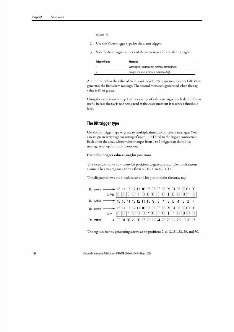
8/17/2019 FactoryTalk® View Machine Edition User's Guide
http://slidepdf.com/reader/full/factorytalk-view-machine-edition-users-guide 130/587
Chapter 9 Set up alarms
130 Rockwell Automation Publication - VIEWME-UM004L-EN-E – March 2016
else 0
2. Use the Value trigger type for the alarm trigger.
3.
Specify these trigger values and alarm messages for the alarm trigger:
Trigger Value Message
1 Warning! The acid tank has exceeded safe fill levels.
2 Danger! The level in the acid tank is too high.
At runtime, when the value of Acid_tank_level is 75 or greater, FactoryTalk Viewgenerates the first alarm message. The second message is generated when the tag value is 90 or greater.
Using the expression in step 1 allows a range of values to trigger each alarm. This is
useful in case the tag is not being read at the exact moment it reaches a thresholdlevel.
The Bit trigger type
Use the Bit trigger type to generate multiple simultaneous alarm messages. Youcan assign an array tag (consisting of up to 1,024 bits) to the trigger connection.Each bit in the array whose value changes from 0 to 1 triggers an alarm (if amessage is set up for the bit position).
Example: Trigger values using bit positions
This example shows how to use bit positions to generate multiple simultaneousalarms. The array tag uses 32 bits, from N7:0/00 to N7:1/15.
This diagram shows the bit addresses and bit positions for the array tag:
The tag is currently generating alarms at bit positions 2, 6, 12, 21, 22, 26, and 30.
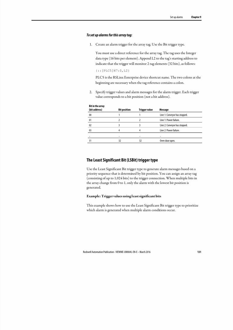
8/17/2019 FactoryTalk® View Machine Edition User's Guide
http://slidepdf.com/reader/full/factorytalk-view-machine-edition-users-guide 131/587
Set up alarms Chapter 9
Rockwell Automation Publication - VIEWME-UM004L-EN-E – March 2016 131
To set up alarms for this array tag:
1. Create an alarm trigger for the array tag. Use the Bit trigger type.
You must use a direct reference for the array tag. The tag uses the Integer
data type (16 bits per element). Append L2 to the tag’s starting address to
indicate that the trigger will monitor 2 tag elements (32 bits), as follows:
{::[PLC5]N7:0,L2}
PLC5 is the RSLinx Enterprise device shortcut name. The two colons at the
beginning are necessary when the tag reference contains a colon.
2. Specify trigger values and alarm messages for the alarm trigger. Each trigger value corresponds to a bit position (not a bit address).
Bit in the array
(bit address) Bit position Trigger value Message
00 1 1 Line 1: Conveyor has stopped.
01 2 2 Line 1: Power failure.
02 3 3 Line 2: Conveyor has stopped.
03 4 4 Line 2: Power failure.
.. .. .. ..
31 32 32 Oven door open.
The Least Significant Bit (LSBit) trigger type
Use the Least Significant Bit trigger type to generate alarm messages based on a priority sequence that is determined by bit position. You can assign an array tag(consisting of up to 1,024 bits) to the trigger connection. When multiple bits inthe array change from 0 to 1, only the alarm with the lowest bit position isgenerated.
Example: Trigger values using least significant bits
This example shows how to use the Least Significant Bit trigger type to prioritize which alarm is generated when multiple alarm conditions occur.
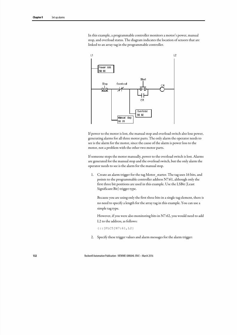
8/17/2019 FactoryTalk® View Machine Edition User's Guide
http://slidepdf.com/reader/full/factorytalk-view-machine-edition-users-guide 132/587
Chapter 9 Set up alarms
132 Rockwell Automation Publication - VIEWME-UM004L-EN-E – March 2016
In this example, a programmable controller monitors a motor’s power, manualstop, and overload status. The diagram indicates the location of sensors that arelinked to an array tag in the programmable controller.
If power to the motor is lost, the manual stop and overload switch also lose power,generating alarms for all three motor parts. The only alarm the operator needs tosee is the alarm for the motor, since the cause of the alarm is power loss to themotor, not a problem with the other two motor parts.
If someone stops the motor manually, power to the overload switch is lost. Alarmsare generated for the manual stop and the overload switch, but the only alarm theoperator needs to see is the alarm for the manual stop.
1. Create an alarm trigger for the tag Motor_starter. The tag uses 16 bits, and points to the programmable controller address N7:61, although only thefirst three bit positions are used in this example. Use the LSBit (LeastSignificant Bit) trigger type.
Because you are using only the first three bits in a single tag element, there is
no need to specify a length for the array tag in this example. You can use a
simple tag type.
However, if you were also monitoring bits in N7:62, you would need to add
L2 to the address, as follows:
{::[PLC5]N7:61,L2}
2. Specify these trigger values and alarm messages for the alarm trigger:
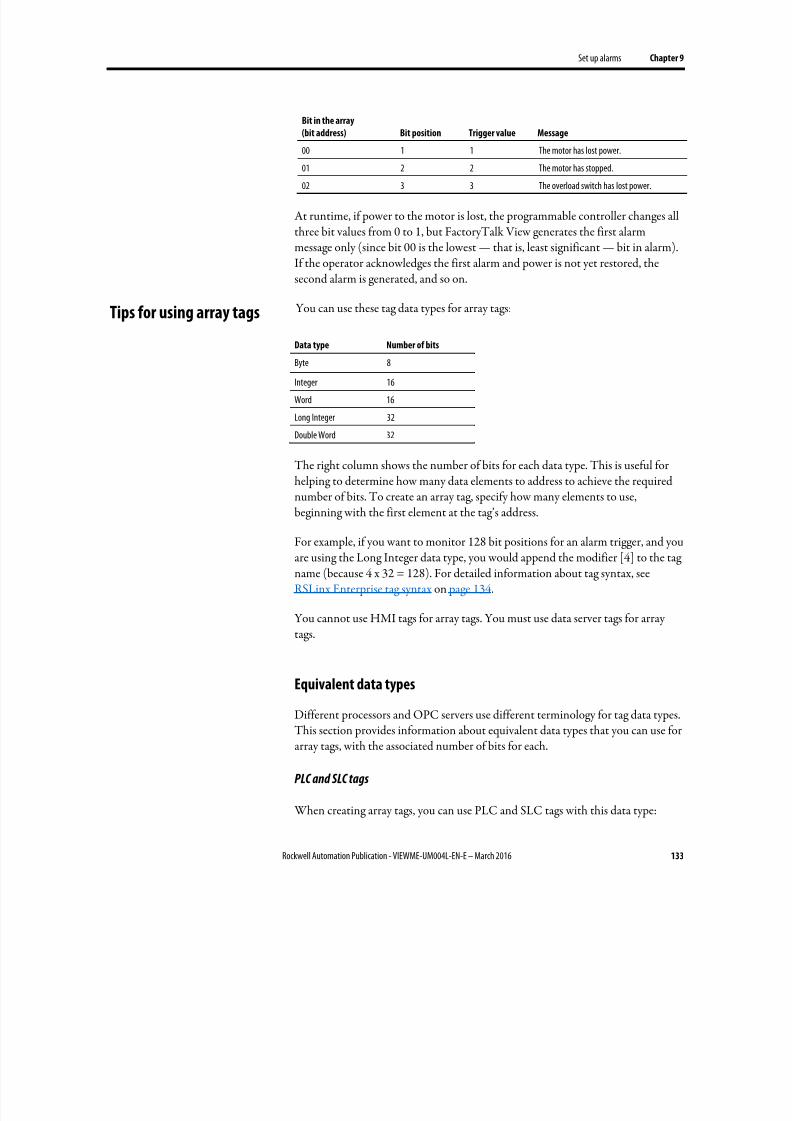
8/17/2019 FactoryTalk® View Machine Edition User's Guide
http://slidepdf.com/reader/full/factorytalk-view-machine-edition-users-guide 133/587
Set up alarms Chapter 9
Rockwell Automation Publication - VIEWME-UM004L-EN-E – March 2016 133
Bit in the array
(bit address) Bit position Trigger value Message
00 1 1 The motor has lost power.
01 2 2 The motor has stopped.02 3 3 The overload switch has lost power.
At runtime, if power to the motor is lost, the programmable controller changes allthree bit values from 0 to 1, but FactoryTalk View generates the first alarmmessage only (since bit 00 is the lowest — that is, least significant — bit in alarm).If the operator acknowledges the first alarm and power is not yet restored, thesecond alarm is generated, and so on.
You can use these tag data types for array tags:
Data type Number of bitsByte 8
Integer 16
Word 16
Long Integer 32
Double Word 32
The right column shows the number of bits for each data type. This is useful forhelping to determine how many data elements to address to achieve the requirednumber of bits. To create an array tag, specify how many elements to use,beginning with the first element at the tag’s address.
For example, if you want to monitor 128 bit positions for an alarm trigger, and youare using the Long Integer data type, you would append the modifier [4] to the tagname (because 4 x 32 = 128). For detailed information about tag syntax, seeRSLinx Enterprise tag syntax on page 134.
You cannot use HMI tags for array tags. You must use data server tags for arraytags.
Equivalent data types
Different processors and OPC servers use different terminology for tag data types.This section provides information about equivalent data types that you can use forarray tags, with the associated number of bits for each.
PLC and SLC tags
When creating array tags, you can use PLC and SLC tags with this data type:
Tips for using array tags
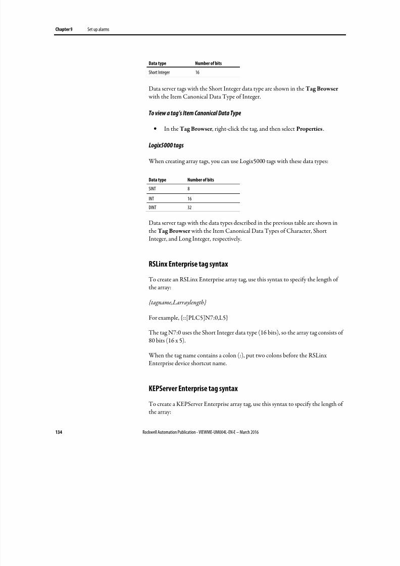
8/17/2019 FactoryTalk® View Machine Edition User's Guide
http://slidepdf.com/reader/full/factorytalk-view-machine-edition-users-guide 134/587
Chapter 9 Set up alarms
134 Rockwell Automation Publication - VIEWME-UM004L-EN-E – March 2016
Data type Number of bits
Short Integer 16
Data server tags with the Short Integer data type are shown in the Tag Browser with the Item Canonical Data Type of Integer.
To view a tag’s Item Canonical Data Type
• In the Tag Browser , right-click the tag, and then select Properties.
Logix5000 tags
When creating array tags, you can use Logix5000 tags with these data types:
Data type Number of bits
SINT 8
INT 16
DINT 32
Data server tags with the data types described in the previous table are shown inthe Tag Browser with the Item Canonical Data Types of Character, ShortInteger, and Long Integer, respectively.
RSLinx Enterprise tag syntax
To create an RSLinx Enterprise array tag, use this syntax to specify the length ofthe array:
{tagname,Larraylength}
For example, {::[PLC5]N7:0,L5}
The tag N7:0 uses the Short Integer data type (16 bits), so the array tag consists of80 bits (16 x 5).
When the tag name contains a colon (:), put two colons before the RSLinxEnterprise device shortcut name.
KEPServer Enterprise tag syntax
To create a KEPServer Enterprise array tag, use this syntax to specify the length ofthe array:
8/17/2019 FactoryTalk® View Machine Edition User's Guide
http://slidepdf.com/reader/full/factorytalk-view-machine-edition-users-guide 135/587
Set up alarms Chapter 9
Rockwell Automation Publication - VIEWME-UM004L-EN-E – March 2016 135
tagname [ arraylength]
For example, Chan1.Dev1.Tag1 [3]
The tag Tag1 uses the Long Integer data type (32 bits), so the array tag consists of96 bits (32 x 3).
Alternatively, you can define the tag length in KEPServer Enterprise when youcreate the tag, and then just select the tag name in FactoryTalk View Studio. Formore information, see KEPServer Enterprise Help.
FactoryTalk View 5.00 and later supports alarm messages in multiple languages. When you create alarm messages, they are in the current application language.You can export the alarm messages for translation and then import them backinto the application. For details, see Set up language switching on page 199.
When an operator acknowledges an alarm, the acknowledge time is recorded inthe alarm log file and the alarm is silenced. This might be all you require of youralarm system.
However, you can use the optional alarm connections in the Alarm Setup editorto set up more sophisticated interactions with the data source when alarms aretriggered, acknowledged, silenced, and reset. For example, you can set up the datasource to acknowledge, silence, and reset alarms. You can also use optional alarmconnections to close the alarm display or to allow the data source to close thealarm display.
There are two sets of optional alarm connections:
• Connections that work with a specific alarm trigger. You can assign adifferent set of connections to each alarm trigger.
• Connections that apply to all alarms
You can also assign connections to alarm lists, to allow the data source todetermine which types of alarms to show in the lists. For more information, seeHow the alarm list graphic object works on page 150.
You can assign a different set of these connections to each alarm trigger, or to onlyone or some alarm triggers:
• Handshake — Assign a tag to this connection to notify the data source when the trigger’s value changes.
• Ack — Assign a tag to this connection to notify the data source when theoperator acknowledges an alarm (or all alarms).
• Remote Ack — Assign a tag or an expression to this connection to allowthe data source to acknowledge alarms.
Create alarm messages in
multiple languages
Optional alarm connections
Connections that work witha specific alarm trigger
8/17/2019 FactoryTalk® View Machine Edition User's Guide
http://slidepdf.com/reader/full/factorytalk-view-machine-edition-users-guide 136/587
Chapter 9 Set up alarms
136 Rockwell Automation Publication - VIEWME-UM004L-EN-E – March 2016
• Remote Ack Handshake — Assign a tag to this connection to notify thedata source when a remote acknowledgement occurs.
• Message — Assign a tag to this connection to send alarm messages to the
connection. Make sure the tag supports the type of data sent in the alarmmessage. For example, if the message is a string of text, assign a string tag tothe Message connection.
• Message Notification — Assign a tag to this connection to notifyFactoryTalk View that an alarm message has been sent to the connectionand FactoryTalk View must wait before sending a new message.
• Message Handshake — Assign a tag to this connection if you want thedata source to notify FactoryTalk View when it has read the message.
Assign tags or expressions to these connections when you create your alarm
triggers. For more detailed information about how these connections work, see thenext sections.
How the Handshake connection works
The Handshake connection is useful for triggers that use the Value data type.Program the data source to queue alarm notifications when multiple alarms aregenerated for the same trigger. Use the Handshake connection to notify the datasource that FactoryTalk View has detected the alarm notification. Then the datasource can send the next alarm to FactoryTalk View.
When the application starts, the Handshake connection has a value of 1. Whenthe trigger connection’s value changes, the Handshake connection’s value togglesfrom 1 to 0. The next time the trigger value changes, the Handshake connection’s value toggles from 0 to 1.
A change in the trigger connection’s value does not necessarily indicate an alarm.The value might still be within acceptable limits.
How the Ack connection works
When the application starts, this connection has a value of 0.
How the value changes
• When the operator acknowledges an alarm by pressing the acknowledgealarm button, FactoryTalk View sends the alarm’s trigger value (or bit position, for bit triggers) to this connection, and holds the value as long asthe operator presses the button, or for the duration of the hold time, whichever is longer. Then the connection’s value is reset to 0.
8/17/2019 FactoryTalk® View Machine Edition User's Guide
http://slidepdf.com/reader/full/factorytalk-view-machine-edition-users-guide 137/587
Set up alarms Chapter 9
Rockwell Automation Publication - VIEWME-UM004L-EN-E – March 2016 137
• When the operator acknowledges all alarms, or the alarms for this triggeronly, by pressing the acknowledge all alarms button, FactoryTalk Viewsends the trigger’s Acknowledge all value to this connection, and holds the value as long as the operator presses the button, or for the duration of thehold time, whichever is longer. Then the connection’s value is reset to 0.
• When the Remote Ack connection changes to a new non-zero value thatmatches the trigger value of an unacknowledged alarm, FactoryTalk Viewsends the trigger’s value (or bit position, for bit triggers) to this connection,and holds the value for the duration of the hold time. Then theconnection’s value is reset to 0.
To avoid confusion about whether a specific trigger’s alarm individual alarm hasbeen acknowledged or all alarms for the trigger have been acknowledged, makesure the Acknowledge all value is not the same as one of the trigger values.
How the Remote Ack connection works
The Remote Ack connection allows for the remote acknowledgement of alarms.The data source writes the alarm’s trigger value (or bit position, for bit triggers) tothis connection, and the unacknowledged alarm with this trigger value isacknowledged.
If you assign this connection and specify an Acknowledge all value for the trigger, when the data source sends the Acknowledge all value to this connection, all
unacknowledged alarms for the trigger are acknowledged.
Make sure that the Acknowledge all value is not the same as one of the trigger values.
Set up the data source to send the correct value to the Remote Ack connection when you want a remote acknowledgement to take place.
Remote acknowledgement does not take place if the hold time is in effect for the Ack connection.
Tip: An alarm’s Trigger and Remote Ack settings should not be configured to use the same
tag. Doing so may cause unpredictable alarm acknowledgement behaviors.
Example: Use the Remote Ack connection
This example shows how to use the Remote Ack connection to acknowledge analarm.
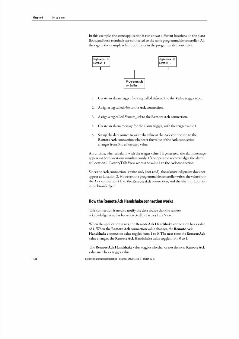
8/17/2019 FactoryTalk® View Machine Edition User's Guide
http://slidepdf.com/reader/full/factorytalk-view-machine-edition-users-guide 138/587
Chapter 9 Set up alarms
138 Rockwell Automation Publication - VIEWME-UM004L-EN-E – March 2016
In this example, the same application is run at two different locations on the plantfloor, and both terminals are connected to the same programmable controller. Allthe tags in the example refer to addresses in the programmable controller.
1. Create an alarm trigger for a tag called Alarm. Use the Value trigger type.
2.
Assign a tag called Ack to the Ack connection.
3. Assign a tag called Remote_ack to the Remote Ack connection.
4. Create an alarm message for the alarm trigger, with the trigger value 1.
5. Set up the data source to write the value at the Ack connection to theRemote Ack connection whenever the value of the Ack connectionchanges from 0 to a non-zero value.
At runtime, when an alarm with the trigger value 1 is generated, the alarm message
appears at both locations simultaneously. If the operator acknowledges the alarmat Location 1, FactoryTalk View writes the value 1 to the Ack connection.
Since the Ack connection is write-only (not read), the acknowledgement does notappear at Location 2. However, the programmable controller writes the value fromthe Ack connection (1) to the Remote Ack connection, and the alarm at Location2 is acknowledged.
How the Remote Ack Handshake connection works
This connection is used to notify the data source that the remoteacknowledgement has been detected by FactoryTalk View.
When the application starts, the Remote Ack Handshake connection has a valueof 1. When the Remote Ack connection value changes, the Remote Ack
Handshake connection value toggles from 1 to 0. The next time the Remote Ack value changes, the Remote Ack Handshake value toggles from 0 to 1.
The Remote Ack Handshake value toggles whether or not the new Remote Ack value matches a trigger value.
8/17/2019 FactoryTalk® View Machine Edition User's Guide
http://slidepdf.com/reader/full/factorytalk-view-machine-edition-users-guide 139/587
Set up alarms Chapter 9
Rockwell Automation Publication - VIEWME-UM004L-EN-E – March 2016 139
This section explains how the Message, Message Notification, and Message
Handshake connections work.
To ensure an alarm message is read by the data source before FactoryTalk View
sends a new message, use message handshaking. While message handshaking is ineffect for an alarm message, FactoryTalk View cannot send a new message to thealarm trigger’s Message connection.
Methods of alarm message handshaking
Alarm handshaking works by setting the alarm trigger’s Message Notification connection to 1. As long as the Message Notification connection is set to 1, newmessages cannot be sent to the Messages connection. How the Message
Notification connection is reset to 0 depends on how you set up alarm messagehandshaking.
There are two ways you can use alarm message handshaking:
• To hold the message at the data source for a specific period of time.
• To hold the message at the data source until the data source notifiesFactoryTalk View that the message has been read.
Choose the method that best suits your application needs and communicationsystem.
Hold the message for a specific period of time
To set up an alarm trigger’s alarm message handshaking so that the message at theMessage connection is held for a specific period of time, assign a tag to theMessage Notification connection and specify a hold time on the Advanced tab ofthe Alarm Setup editor.
How handshaking works
This method of alarm message handshaking works as follows:
1. When an alarm occurs, the alarm message is sent to the Messageconnection.
2. The Message Notification connection is set to 1.
As long as the Message Notification connection is set to 1, FactoryTalk
View cannot send new messages to the data source.
Ensure alarm messages are
read by the data source
before sending newmessages
8/17/2019 FactoryTalk® View Machine Edition User's Guide
http://slidepdf.com/reader/full/factorytalk-view-machine-edition-users-guide 140/587
Chapter 9 Set up alarms
140 Rockwell Automation Publication - VIEWME-UM004L-EN-E – March 2016
3. The hold time timer begins timing.
4. When the hold time has expired, the Message Notification connection isreset to 0 and FactoryTalk View can send a new message to the Message
connection.
Hold the message until the data source acknowledges that it has read
the message
To set up an alarm trigger’s alarm message handshaking so that the message at theMessage connection is held until the data source notifies FactoryTalk View that ithas read the message, use two connections: the Message Notification connectionand the Message Handshake connection.
Set up the data source to send a new non-zero value to the Message Handshake connection when it has read the message at the Message connection.
How handshaking works
If you use the Message Handshake connection, handshaking works like this:
1. When an alarm occurs, the alarm message is sent to the Message
connection.
2. The Message Notification connection is set to 1.
As long as the Message Notification connection is set to 1, FactoryTalk
View cannot send new messages to the data source.
3. When the data source has read the message, it sends a new non-zero value tothe Message Handshake connection.
4. The Message Notification connection is reset to 0 and FactoryTalk Viewcan send a new message to the Message connection.
How messages are queued
FactoryTalk View can queue up to 128 messages while it waits for the MessageNotification connection to be reset to 0. Queued messages are sent to the datasource on a first in, first out basis.
If the alarm message queue fills before the Message Notification connection isreset to 0, an error message is sent to FactoryTalk Diagnostics.
8/17/2019 FactoryTalk® View Machine Edition User's Guide
http://slidepdf.com/reader/full/factorytalk-view-machine-edition-users-guide 141/587
Set up alarms Chapter 9
Rockwell Automation Publication - VIEWME-UM004L-EN-E – March 2016 141
How the Message connection works
This connection is used to send the message associated with a trigger value to the
data source.
The message is sent only if the alarm message’s Message to Tag option is selected.
If you are going to generate text alarm messages in multiple languages, make surethe tag assigned to this connection can accommodate the string length of themessages in each language. For information about using multiple languages, see Setup language switching on page 199.
How the Message Notification connection works
This connection is used to notify FactoryTalk View that an alarm message hasbeen sent to the data source and FactoryTalk View must wait to send anothermessage.
When the application starts, the Message Notification connection is set to 0. When a message is written to the Message connection, the Message Notification connection value changes to 1. When the hold time expires, or the MessageHandshake connection changes to a new non-zero value, the Message
Notification connection value changes from 1 to 0.
Messages for an alarm trigger are queued if the Message Notification connection
is set to 1.
How the Message Handshake connection works
Use the Message Handshake connection to reset the Message Notification connection when the data source has read the alarm message.
Set up the data source to send a new non-zero value to the Message Handshake connection when it has read the message at the Message connection.
These connections apply to all alarms:
• Silence — Assign a tag to this connection to notify the data source that allalarms have been silenced (for applications that will run on a personalcomputer only).
• Remote Silence — Assign a tag or an expression to this connection to allowthe data source to silence all alarms (for applications that will run on a personal computer only).
Connections that apply toall alarms
8/17/2019 FactoryTalk® View Machine Edition User's Guide
http://slidepdf.com/reader/full/factorytalk-view-machine-edition-users-guide 142/587
Chapter 9 Set up alarms
142 Rockwell Automation Publication - VIEWME-UM004L-EN-E – March 2016
• Remote Ack All — Assign a tag to this connection to allow the data sourceto acknowledge all alarms at once.
• Status Reset — Assign a tag to this connection to notify the data source
that the alarm status has been reset.
• Remote Status Reset — Assign a tag or expression to this connection toallow the data source to reset the alarm status.
• Close Display — Assign a tag to this connection to notify the data sourcethat the alarm display has closed.
• Remote Close Display — Assign a tag or expression to this connection toallow the data source to close the alarm display.
Assign tags or expressions to these connections in the Advanced tab of the Alarm
Setup editor. For more detailed information about how these connections work,see the next sections.
How the Silence connection works
When the application starts, this connection has a value of 0. When alarms aresilenced, this connection is set to 1 for the hold time and the internal beeper isturned off. At the end of the hold time, the connection is reset to 0.
If the silence event is triggered by a button press, this connection is set to 1 for thehold time or for the duration of the button press, whichever is longer. At the end
of this time, the connection is reset to 0.
If subsequent alarms (that have been set up to sound the internal beeper) aregenerated, the alarms sound the beeper regardless of the Silence connection valueor hold time status.
While the hold time is in effect, new alarms cannot be silenced.
How the Remote Silence connection works
When this connection changes to a new non-zero value, all alarms are silenced.Alarms can be silenced using other methods regardless of this connection’s value.
Set up the data source to send a new non-zero value to the Remote Silence connection each time you want a remote silencing of alarms to take place.
8/17/2019 FactoryTalk® View Machine Edition User's Guide
http://slidepdf.com/reader/full/factorytalk-view-machine-edition-users-guide 143/587
Set up alarms Chapter 9
Rockwell Automation Publication - VIEWME-UM004L-EN-E – March 2016 143
How the Remote Ack All connection works
When this connection changes to a new non-zero value, all unacknowledged
alarms are acknowledged.
Set up the data source to send a new non-zero value to the Remote Ack Allconnection each time you want a remote acknowledgement of all alarms to take place.
How the Status Reset connection works
When the application starts, this connection has a value of 0. If a reset alarm statusor clear alarm history button is pressed, this connection is set to 1 for the holdtime or for the duration of the button press, whichever is longer. At the end of thistime, the connection is reset to 0.
The Status Reset connection is also set to 1 if the Remote Status Reset connection changes to a new non-zero value, and remains set for the hold time.
While the hold time is in effect, the alarm status cannot be reset again. The statusof alarms keeps updating during the hold time.
How the Remote Status Reset connection works
When this connection changes to a new non-zero value, the status of all alarms isreset, as described in Methods for resetting alarms on page 127. Alarms can bereset using other methods regardless of this connection’s value.
Set up the data source to send a new non-zero value to the Remote Status Resetconnection each time you want a remote resetting of alarm status to take place.
How the Close Display connection works
When the application starts, this connection has a value of 0. If the alarm display
(assigned in the Alarm Setup editor) closes, this connection is set to 1 for the holdtime. At the end of the hold time, the connection is reset to 0.
If subsequent alarms are generated, the alarm display opens again regardless of theClose Display connection value or hold time status.
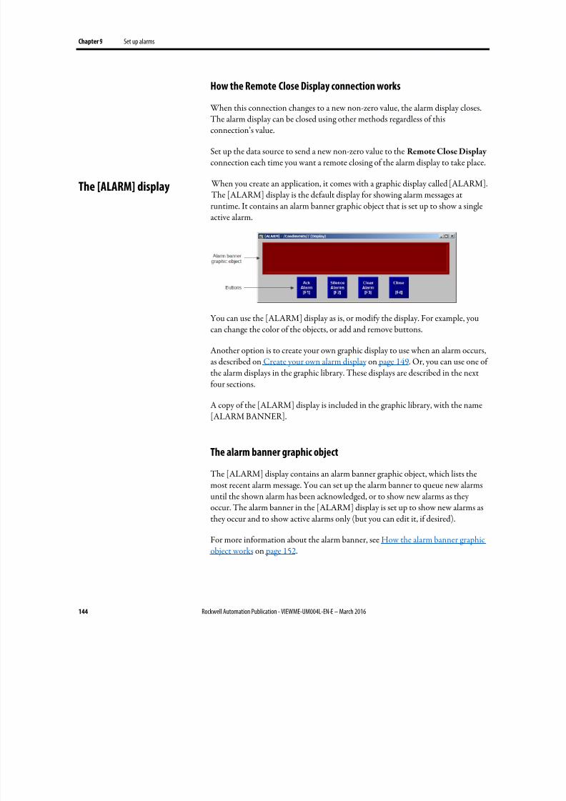
8/17/2019 FactoryTalk® View Machine Edition User's Guide
http://slidepdf.com/reader/full/factorytalk-view-machine-edition-users-guide 144/587
Chapter 9 Set up alarms
144 Rockwell Automation Publication - VIEWME-UM004L-EN-E – March 2016
How the Remote Close Display connection works
When this connection changes to a new non-zero value, the alarm display closes.
The alarm display can be closed using other methods regardless of thisconnection’s value.
Set up the data source to send a new non-zero value to the Remote Close Display connection each time you want a remote closing of the alarm display to take place.
When you create an application, it comes with a graphic display called [ALARM].The [ALARM] display is the default display for showing alarm messages atruntime. It contains an alarm banner graphic object that is set up to show a singleactive alarm.
You can use the [ALARM] display as is, or modify the display. For example, youcan change the color of the objects, or add and remove buttons.
Another option is to create your own graphic display to use when an alarm occurs,as described on Create your own alarm display on page 149. Or, you can use one of
the alarm displays in the graphic library. These displays are described in the nextfour sections.
A copy of the [ALARM] display is included in the graphic library, with the name[ALARM BANNER].
The alarm banner graphic object
The [ALARM] display contains an alarm banner graphic object, which lists themost recent alarm message. You can set up the alarm banner to queue new alarms
until the shown alarm has been acknowledged, or to show new alarms as theyoccur. The alarm banner in the [ALARM] display is set up to show new alarms asthey occur and to show active alarms only (but you can edit it, if desired).
For more information about the alarm banner, see How the alarm banner graphicobject works on page 152.
The [ALARM] display
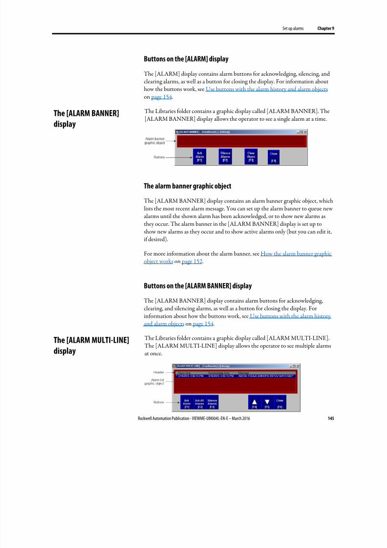
8/17/2019 FactoryTalk® View Machine Edition User's Guide
http://slidepdf.com/reader/full/factorytalk-view-machine-edition-users-guide 145/587
Set up alarms Chapter 9
Rockwell Automation Publication - VIEWME-UM004L-EN-E – March 2016 145
Buttons on the [ALARM] display
The [ALARM] display contains alarm buttons for acknowledging, silencing, and
clearing alarms, as well as a button for closing the display. For information abouthow the buttons work, see Use buttons with the alarm history and alarm objects on page 154.
The Libraries folder contains a graphic display called [ALARM BANNER]. The[ALARM BANNER] display allows the operator to see a single alarm at a time.
The alarm banner graphic object
The [ALARM BANNER] display contains an alarm banner graphic object, whichlists the most recent alarm message. You can set up the alarm banner to queue newalarms until the shown alarm has been acknowledged, or to show new alarms asthey occur. The alarm banner in the [ALARM BANNER] display is set up toshow new alarms as they occur and to show active alarms only (but you can edit it,if desired).
For more information about the alarm banner, see How the alarm banner graphicobject works on page 152.
Buttons on the [ALARM BANNER] display
The [ALARM BANNER] display contains alarm buttons for acknowledging,clearing, and silencing alarms, as well as a button for closing the display. Forinformation about how the buttons work, see Use buttons with the alarm historyand alarm objects on page 154.
The Libraries folder contains a graphic display called [ALARM MULTI-LINE].The [ALARM MULTI-LINE] display allows the operator to see multiple alarmsat once.
The [ALARM BANNER]
display
The [ALARM MULTI-LINE]display
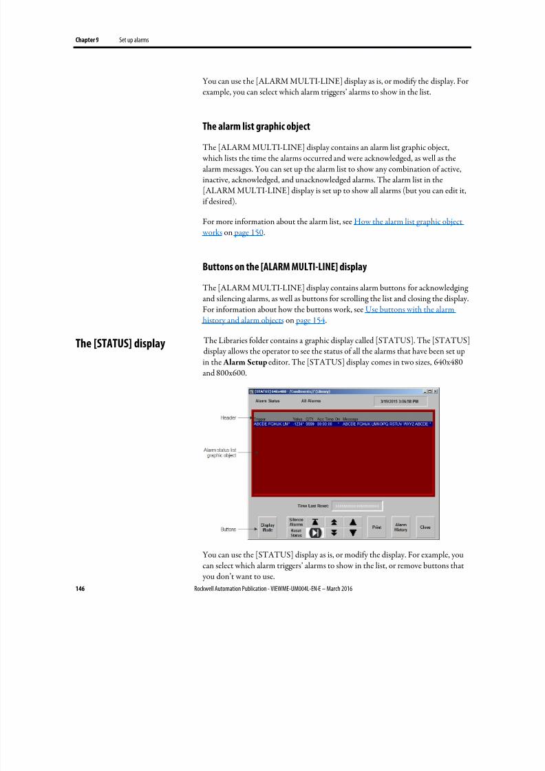
8/17/2019 FactoryTalk® View Machine Edition User's Guide
http://slidepdf.com/reader/full/factorytalk-view-machine-edition-users-guide 146/587
Chapter 9 Set up alarms
146 Rockwell Automation Publication - VIEWME-UM004L-EN-E – March 2016
You can use the [ALARM MULTI-LINE] display as is, or modify the display. Forexample, you can select which alarm triggers’ alarms to show in the list.
The alarm list graphic object
The [ALARM MULTI-LINE] display contains an alarm list graphic object, which lists the time the alarms occurred and were acknowledged, as well as thealarm messages. You can set up the alarm list to show any combination of active,inactive, acknowledged, and unacknowledged alarms. The alarm list in the[ALARM MULTI-LINE] display is set up to show all alarms (but you can edit it,if desired).
For more information about the alarm list, see How the alarm list graphic object works on page 150.
Buttons on the [ALARM MULTI-LINE] display
The [ALARM MULTI-LINE] display contains alarm buttons for acknowledgingand silencing alarms, as well as buttons for scrolling the list and closing the display.For information about how the buttons work, see Use buttons with the alarmhistory and alarm objects on page 154.
The Libraries folder contains a graphic display called [STATUS]. The [STATUS]display allows the operator to see the status of all the alarms that have been set up
in the Alarm Setup editor. The [STATUS] display comes in two sizes, 640x480and 800x600.
You can use the [STATUS] display as is, or modify the display. For example, youcan select which alarm triggers’ alarms to show in the list, or remove buttons that you don’t want to use.
The [STATUS] display
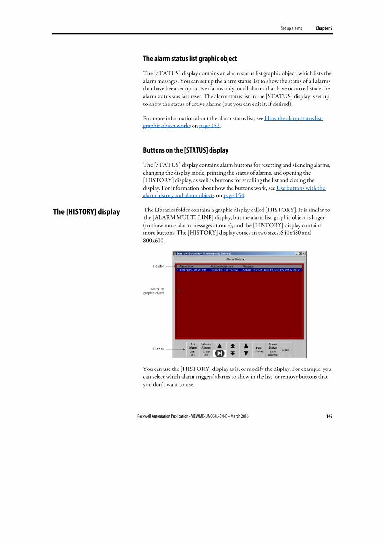
8/17/2019 FactoryTalk® View Machine Edition User's Guide
http://slidepdf.com/reader/full/factorytalk-view-machine-edition-users-guide 147/587
Set up alarms Chapter 9
Rockwell Automation Publication - VIEWME-UM004L-EN-E – March 2016 147
The alarm status list graphic object
The [STATUS] display contains an alarm status list graphic object, which lists the
alarm messages. You can set up the alarm status list to show the status of all alarmsthat have been set up, active alarms only, or all alarms that have occurred since thealarm status was last reset. The alarm status list in the [STATUS] display is set upto show the status of active alarms (but you can edit it, if desired).
For more information about the alarm status list, see How the alarm status listgraphic object works on page 152.
Buttons on the [STATUS] display
The [STATUS] display contains alarm buttons for resetting and silencing alarms,changing the display mode, printing the status of alarms, and opening the[HISTORY] display, as well as buttons for scrolling the list and closing thedisplay. For information about how the buttons work, see Use buttons with thealarm history and alarm objects on page 154.
The Libraries folder contains a graphic display called [HISTORY]. It is similar tothe [ALARM MULTI-LINE] display, but the alarm list graphic object is larger(to show more alarm messages at once), and the [HISTORY] display containsmore buttons. The [HISTORY] display comes in two sizes, 640x480 and800x600.
You can use the [HISTORY] display as is, or modify the display. For example, youcan select which alarm triggers’ alarms to show in the list, or remove buttons that you don’t want to use.
The [HISTORY] display
8/17/2019 FactoryTalk® View Machine Edition User's Guide
http://slidepdf.com/reader/full/factorytalk-view-machine-edition-users-guide 148/587
Chapter 9 Set up alarms
148 Rockwell Automation Publication - VIEWME-UM004L-EN-E – March 2016
The alarm list graphic object
The [HISTORY] display contains an alarm list graphic object, which lists the time
the alarms occurred and were acknowledged, as well as the alarm messages.
You can set up the alarm list to show any combination of active, inactive,acknowledged, and unacknowledged alarms. The alarm list in the [HISTORY]display is set up to show all alarms (but you can edit it, if desired).
For more information about the alarm list, see How the alarm list graphic object works on page 150.
Buttons on the [HISTORY] display
The [HISTORY] display contains alarm buttons for acknowledging, silencing,and clearing alarms, sorting the list of alarms, printing the alarm history list, andopening the [STATUS] display, as well as buttons for scrolling the list and closingthe display. For information about how the buttons work, see Use buttons withthe alarm history and alarm objects on page 154.
The previous four sections described the [ALARM BANNER], [ALARMMULTI-LINE], [STATUS], and [HISTORY] displays that are included in theLibraries folder. You can copy objects from the displays to your own display, or you can copy the entire displays into your application.
For information about copying objects from a library into your graphic display, seeCopy objects on page 376.
The graphic libraries are available on the development computer, but do notappear at runtime. To use a display in the library as a graphic display at runtime, you must add the library display into your application’s folder of graphic displays.For details, see Use libraries as displays in your application on page 319.
Example: Use the [ALARM] and [STATUS] displays together
To use the [ALARM] display to alert the operator about alarms as they occur, and
the [STATUS] display to show how many times and for how long alarms havebeen active:
1. In the Alarm Setup editor, in the Advanced tab, select the [ALARM]display as the display to open when alarms are triggered, if it is not alreadyselected. (It is selected by default.)
2. Add the [STATUS] display from the library.
Use displays from the
library in your application
8/17/2019 FactoryTalk® View Machine Edition User's Guide
http://slidepdf.com/reader/full/factorytalk-view-machine-edition-users-guide 149/587
Set up alarms Chapter 9
Rockwell Automation Publication - VIEWME-UM004L-EN-E – March 2016 149
3. Edit the [ALARM] display by adding a Goto display button that opens the[STATUS] display when pressed.
You can create your own graphic display for displaying and responding to alarms.
For example, you could create a display with a static text object that notifies theoperator that an alarm has occurred, and a Goto display button that the operatorcan press to open a display that lists the actual alarm message.
If you create your own graphic display, use an On Top display and select theCannot Be Replaced option.
For information about the graphic objects you can use to show alarm information,see the information starting on How the alarm list graphic object works on page150. For information about creating graphic displays and graphic objects, see Usegraphic displays on page 303 and Use graphic objects on page 335.
Open the display
The alarm display you specify on the Advanced tab of the Alarm Setup editor(the default [ALARM] display, a display you copy from the library, or your owndisplay) is automatically opened whenever a trigger connection’s value matches atrigger value (if you selected the Display option for the trigger value).
You can also create a Goto display button that the operator can press to open thealarm display. For information about setting up a Goto display button and
specifying the display to open, see Help.
Close the display
The operator can close the display by pressing a Close Display button.
The display closes automatically under these circumstances:
• When the operator presses an acknowledge all alarms button and causes thenewest alarm in the alarm history to be acknowledged.
•
When the operator presses a clear alarm history button and causes thenewest alarm in the alarm history to be deleted.
• When the Remote Close Display connection changes to a new non-zero value.
• When the Remote Ack All connection changes to a new non-zero value.
• When the newest alarm is acknowledged.
Create your own alarmdisplay
Open and close the alarm
display
8/17/2019 FactoryTalk® View Machine Edition User's Guide
http://slidepdf.com/reader/full/factorytalk-view-machine-edition-users-guide 150/587
Chapter 9 Set up alarms
150 Rockwell Automation Publication - VIEWME-UM004L-EN-E – March 2016
If you don’t want the display to close when the newest alarm is acknowledged, youcan turn off this option in FactoryTalk View ME Station.
To change how the display closes
1. In FactoryTalk View ME Station, click Terminal Settings.
2. Double-click Alarms.
3. Specify how you want the display to close.
The alarm list graphic object shows the time an alarm was triggered, and the timeit was acknowledged (if you set up the object to show acknowledged alarms).
At runtime, when a trigger connection at the data source matches a message’s
trigger value, an alarm appears in the alarm list. The alarm list can be in the[ALARM MULTI-LINE] or [HISTORY] display, in an alarm display you havecreated, or can be placed on any display in your application.
You can use multiple alarm lists, in the same display or in different displays. Eachalarm list displays information from the same alarm log file, although you can setup different lists to display different information.
For information about setting up alarm lists, see Help.
What is shown
• If you set up the list to show the alarms for specific alarm triggers, onlyalarms for those triggers are shown.
• If the list is set up to show unacknowledged alarms only, the alarms shownin the list are unacknowledged and the acknowledge time column, if any, isalways blank.
• If the list is set up to show both acknowledged and unacknowledged alarms,acknowledged alarms can show a symbol (which you can specify) at the leftend of the row, and the acknowledge time appears in the acknowledge time
column, if shown.• If the list is set up to show both active and inactive alarms, active alarms can
show a symbol (which you can specify) at the left end of the row. If both theacknowledge symbol and active symbol are shown, the active symbolcolumn is to the right of the acknowledge symbol column.
• If the message is too long to fit in the object, the last shown character isreplaced with an asterisk. Similarly, if a column heading is too long to fit inthe column, the last shown character is replaced with an asterisk. You canspecify how many lines to allow for each alarm message, from 1 to 10.
How the alarm list graphic
object works
8/17/2019 FactoryTalk® View Machine Edition User's Guide
http://slidepdf.com/reader/full/factorytalk-view-machine-edition-users-guide 151/587
Set up alarms Chapter 9
Rockwell Automation Publication - VIEWME-UM004L-EN-E – March 2016 151
• The number of alarm messages that fits on the display depends on theheight of the alarm list, the list’s font size, how many lines you have specifiedfor each alarm message, and whether the column headings are shown.
•
If alarms are currently being sorted by time, alarms are listed with thenewest alarms on top.
• If alarms are currently being sorted by trigger value, alarms from the firsttrigger in the Alarm Setup editor are listed first, with alarms fromsubsequent triggers listed after. Alarms in the list from the same trigger aregrouped together and then sorted by trigger value, from lowest to highest.
• If there are multiple instances of the same alarm, these alarms are sorted bytime with the newest on top.
• If you assign a tag or expression to any of the ActiveAcknowledged,ActiveUnacknowledged, InactiveAcknowledged, orInactiveUnacknowledged connections, when a connection’s value is anon-zero value, the related type of alarm is shown in the alarm list. Theconnection value overrides the setting for the list in the Alarm List
Properties dialog box.
• If you set up alarm messages in multiple languages, messages are shown inthe language that they were originally logged in. All alarm andacknowledgement times are shown in the current application language.
How the list scrolls
• When a display containing an alarm list is opened, the highlight bar orcursor is at the top of the list: on the most recent alarm if sorted by time; oron the first alarm for the first trigger, if sorted by trigger value.
• If alarms are sorted by time, and the top alarm is selected, as new alarmsoccur, the old alarms scroll down, but the highlight bar or cursor remains atthe top.
• If alarms are sorted by time, when the operator selects an alarm other thanthe top one in the list (by using the move down button), and new alarmsoccur, they are added above the visible area if the list is full. The currently
selected alarm continues to be selected and maintains its position in theshown portion of the list.
• If alarms are sorted by trigger value, as new alarms occur the currentlyselected alarm continues to be selected and maintains its position in the list.
• If the sort order changes, the selected alarm continues to be selected, but itmight be displayed in a different position in the list.

8/17/2019 FactoryTalk® View Machine Edition User's Guide
http://slidepdf.com/reader/full/factorytalk-view-machine-edition-users-guide 152/587
Chapter 9 Set up alarms
152 Rockwell Automation Publication - VIEWME-UM004L-EN-E – March 2016
The alarm banner graphic object shows a single, unacknowledged alarm.
At runtime, when a trigger connection at the data source matches a message’strigger value, an alarm appears in the alarm banner. The alarm banner can be in
the [ALARM] display or [ALARM BANNER] display, in an alarm display youhave created, or can be placed on any display in your application.
You can use multiple alarm banners, in the same display or in different displays.You can set up different banners so that one displays the most recent alarm, andthe other queues alarms until the displayed alarm is acknowledged.
For information about setting up alarm banners, see Help.
What is shown
• If you set up the banner to show the alarms for specific alarm triggers, onlyalarms for those triggers are displayed.
• You can set up the banner to queue new alarms until the operator clears thecurrent alarm, or to always display the most recent alarm.
• When a display containing an alarm banner is first opened, the alarmbanner is blank, unless the display is the alarm display specified in the
Alarm Setup editor and it was opened in response to an alarm.
• When the shown alarm is acknowledged, it is removed from the alarmbanner. If there are no newer alarms, the banner is blank.
• If the operator presses a clear alarm banner button, the banner is blank.
• If the operator presses a clear alarm history button or if all alarms areacknowledged, the banner is blank.
• If the banner is set up to show both active and inactive alarms, when analarm is active, an asterisk (*) appears beside the message.
• If you set up alarm messages in multiple languages, messages and triggerlabels are shown in the language that they were originally logged in. Allalarm times are shown in the current application language.
The alarm status list graphic object shows the status of alarms, including whetheran alarm has been triggered, how many times an alarm has been triggered, and forhow long.
The alarm status list can be on the [STATUS] display, on an alarm display youhave created, or can be placed on any display in your application.
You can use multiple alarm status lists, on the same display or on differentdisplays. You can set up different lists to show different information.
How the alarm banner
graphic object works
How the alarm status listgraphic object works

8/17/2019 FactoryTalk® View Machine Edition User's Guide
http://slidepdf.com/reader/full/factorytalk-view-machine-edition-users-guide 153/587
Set up alarms Chapter 9
Rockwell Automation Publication - VIEWME-UM004L-EN-E – March 2016 153
For information about setting up alarm status lists, see Help.
What is shown• If you set up the list to show the alarms for specific alarm triggers, only
alarms for those triggers are shown.
• If an alarm is active, an asterisk (*) appears in the alarm state column, ifshown.
• If the message is too long to fit in the object, the last character that would fitis replaced with an asterisk. Similarly, if a column heading is too long to fitin the column, the last character that would fit is replaced with an asterisk.You can specify how many lines to allow for each alarm message, from 1 to10.
• The number of alarm messages that fits on the display depends on theheight of the alarm status list, the list’s font size, how many lines you havespecified for each alarm message, and whether the column headings areshown.
• For value-triggered alarms, the accumulated time column shows how longthe alarm has been set to the trigger value.
• For bit-triggered alarms, the accumulated time column shows how long thebit has been set to 1.
• For LSBit-triggered alarms, the accumulated time column shows how longthe corresponding alarm’s least significant bit has been set to 1.
• If you set up alarm messages in multiple languages, all messages and triggerlabels are shown in the current application language, regardless of whatlanguage they were originally logged in.
What happens when the display is opened
• The first time a display containing the alarm status list is opened, the first page of alarms is shown.
•
If the list is set up to show active alarms only, and alarms that were visible when the display was closed are no longer active, the alarms are removedfrom the list.
• If alarms have been reset since the display was last opened, the first page ofalarms is shown.
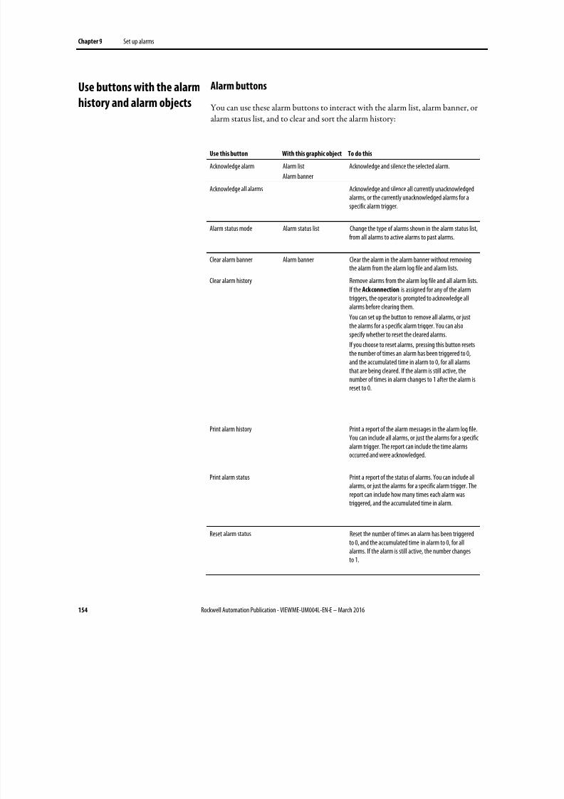
8/17/2019 FactoryTalk® View Machine Edition User's Guide
http://slidepdf.com/reader/full/factorytalk-view-machine-edition-users-guide 154/587
Chapter 9 Set up alarms
154 Rockwell Automation Publication - VIEWME-UM004L-EN-E – March 2016
Alarm buttons
You can use these alarm buttons to interact with the alarm list, alarm banner, or
alarm status list, and to clear and sort the alarm history:
Use this button With this graphic object To do this
Acknowledge alarm Alarm list
Alarm banner
Acknowledge and silence the selected alarm.
Acknowledge all alarms Acknowledge and silence all currently unacknowledgedalarms, or the currently unacknowledged alarms for aspecific alarm trigger.
Alarm status mode Alarm status list Change the type of alarms shown in the alarm status list,from all alarms to active alarms to past alarms.
Clear alarm banner Alarm banner Clear the alarm in the alarm banner without removingthe alarm from the alarm log file and alarm lists.
Clear alarm history Remove alarms from the alarm log file and all alarm lists.If the Ack connection is assigned for any of the alarmtriggers, the operator is prompted to acknowledge allalarms before clearing them.
You can set up the button to remove all alarms, or justthe alarms for a s pecific alarm trigger. You can alsospecify whether to reset the cleared alarms.
If you choose to reset alarms, pressing this button resetsthe number of times an alarm has been triggered to 0,and the accumulated time in alarm to 0, for all alarms
that are being cleared. If the alarm is still active, thenumber of times in alarm changes to 1 after the alarm isreset to 0.
Print alarm history Print a report of the alarm messages in the alarm log file.You can include all alarms, or just the alarms for a specificalarm trigger. The report can include the time alarmsoccurred and were acknowledged.
Print alarm status Print a report of the status of alarms. You can include allalarms, or just the alarms for a specific alarm trigger. The
report can include how many times each alarm wastriggered, and the accumulated time in alarm.
Reset alarm status Reset the number of times an alarm has been triggeredto 0, and the accumulated time in alarm to 0, for allalarms. If the alarm is still active, the number changesto 1.
Use buttons with the alarm
history and alarm objects
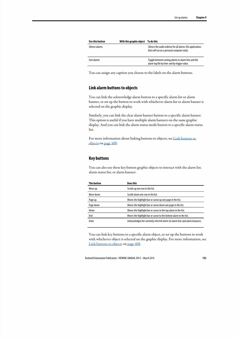
8/17/2019 FactoryTalk® View Machine Edition User's Guide
http://slidepdf.com/reader/full/factorytalk-view-machine-edition-users-guide 155/587
Set up alarms Chapter 9
Rockwell Automation Publication - VIEWME-UM004L-EN-E – March 2016 155
Use this button With this graphic object To do this
Silence alarms Silence the audio indictor for all alarms (for applicationsthat will run on a personal computer only).
Sort alarms Toggle between sorting alarms in alarm lists and thealarm log file by time and by trigger value.
You can assign any caption you choose to the labels on the alarm buttons.
Link alarm buttons to objects
You can link the acknowledge alarm button to a specific alarm list or alarmbanner, or set up the button to work with whichever alarm list or alarm banner is
selected on the graphic display.
Similarly, you can link the clear alarm banner button to a specific alarm banner.This option is useful if you have multiple alarm banners on the same graphicdisplay. And you can link the alarm status mode button to a specific alarm statuslist.
For more information about linking buttons to objects, see Link buttons toobjects on page 408.
Key buttons
You can also use these key button graphic objects to interact with the alarm list,alarm status list, or alarm banner:
This button Does this
Move up Scrolls up one row in the list.
Move down Scrolls down one row in the list.
Page up Moves the highlight bar or cursor up one page in the list.
Page down Moves the highlight bar or cursor down one page in the list.
Home Moves the highlight bar or cursor to the top alarm in the list.
End Moves the highlight bar or cursor to the bottom alarm in the list.
Enter Acknowledges the currently selected alarm (in alarm lists and alarm banners).
You can link key buttons to a specific alarm object, or set up the buttons to work with whichever object is selected on the graphic display. For more information, seeLink buttons to objects on page 408.
8/17/2019 FactoryTalk® View Machine Edition User's Guide
http://slidepdf.com/reader/full/factorytalk-view-machine-edition-users-guide 156/587
Chapter 9 Set up alarms
156 Rockwell Automation Publication - VIEWME-UM004L-EN-E – March 2016
For information about creating graphic objects, see Use graphic objects on page335. For information about setting up key buttons, see Help.
Acknowledging messages does not remove them from the alarm log file. You can
still show acknowledged alarms in an alarm list that is set up to showacknowledged alarms.
Acknowledge the selected alarm
When the operator presses the acknowledge alarm button, an enter button, or theEnter key on an external keyboard or keypad:
• The selected alarm in the alarm list is acknowledged and the audio indicatorfor the alarm, if any, is silenced.
• The shown alarm in the alarm banner is acknowledged and the audioindicator for the alarm, if any, is silenced.
This is what happens when the alarm is acknowledged:
• If assigned, the alarm trigger’s Ack connection is set to the alarm trigger value at the data source. The value is held as long as the operator presses thebutton, or for the hold time, whichever is longer.
If the hold time is still in effect and the operator acknowledges a new
instance of the same alarm, the new acknowledgement is ignored.
• If the alarm list is set up to show unacknowledged alarms only, the alarm isremoved from the list. The highlight bar or cursor moves up to the nextunacknowledged alarm, unless it is already on the top unacknowledgedalarm.
• If the highlight bar or cursor is on an acknowledged alarm when theoperator presses the acknowledge alarm button, the button press is ignored.
• The alarm is removed from the alarm banner.
Acknowledge all alarms
When the operator presses an acknowledge all alarms button, all unacknowledgedalarms in the system (or, optionally, for a specific alarm trigger), are acknowledged.
This is what happens when the alarms are acknowledged:
• For each alarm trigger, to which an Acknowledge all value is assigned, thespecified Acknowledge all value is sent to the trigger’s Ack connection.
Use alarm buttons toacknowledge, silence, clear,
and delete alarms
8/17/2019 FactoryTalk® View Machine Edition User's Guide
http://slidepdf.com/reader/full/factorytalk-view-machine-edition-users-guide 157/587
Set up alarms Chapter 9
Rockwell Automation Publication - VIEWME-UM004L-EN-E – March 2016 157
The value is held as long as the operator presses the button, or for the holdtime, whichever is longer. Then the connection’s value is reset to 0.
If the Acknowledge all value is not assigned for a trigger, no value is sent to
the trigger’s Ack connection.
If the hold time for any alarm is still in effect and the operator presses
acknowledge all alarms, the button press is ignored.
• If the alarm list is set up to display unacknowledged alarms only, allacknowledged alarms are removed from the list.
• The alarm banner is cleared.
Silence alarms
When the operator presses the silence alarms button, any audible signal triggeredby an alarm is silenced and the Silence connection is set to 1 for the hold time orfor the duration of the button press, whichever is longer. Then the connection’s value is reset to 0.
If the hold time for any alarm is still in effect and the operator presses silencealarms, the button press is ignored.
The audio alarm indicator is available for applications running on personalcomputers only.
Clear and delete messages
From the alarm history
When the operator presses the clear alarm history button, all alarms in the system(or, optionally, for a specific alarm trigger) are deleted from the alarm log file andfrom all alarm lists. For information about the alarm log file, see The alarm log file on page 128.
If the Ack connection is assigned for any of the alarm triggers being cleared, theoperator is prompted to acknowledge the unacknowledged messages beforedeleting them. If the operator chooses to acknowledge the alarms, the
Acknowledge all value (if any) is sent to the Ack connection before deleting themessages. If the Ack connection is not assigned, or if the operator chooses not toacknowledge alarms, all messages are deleted immediately.
8/17/2019 FactoryTalk® View Machine Edition User's Guide
http://slidepdf.com/reader/full/factorytalk-view-machine-edition-users-guide 158/587

8/17/2019 FactoryTalk® View Machine Edition User's Guide
http://slidepdf.com/reader/full/factorytalk-view-machine-edition-users-guide 159/587
Set up alarms Chapter 9
Rockwell Automation Publication - VIEWME-UM004L-EN-E – March 2016 159
Change the alarm status shown in the alarm status list
When the operator presses the alarm status mode button, the type of alarms
shown in the alarm status list changes as follows:
• If the current type shown is all alarms, the list changes to show active alarmsonly.
• If the current type shown is active alarms, the list changes to show pastalarms only.
• If the current type shown is past alarms, the list changes to show all alarms.
The change affects the linked or selected alarm status list only, not all alarm statuslists.

8/17/2019 FactoryTalk® View Machine Edition User's Guide
http://slidepdf.com/reader/full/factorytalk-view-machine-edition-users-guide 160/587
Chapter 9 Set up alarms
160 Rockwell Automation Publication - VIEWME-UM004L-EN-E – March 2016
8/17/2019 FactoryTalk® View Machine Edition User's Guide
http://slidepdf.com/reader/full/factorytalk-view-machine-edition-users-guide 161/587
Rockwell Automation Publication - VIEWME-UM004L-EN-E – March 2016 161
Chapter 10
Set up FactoryTalk Diagnostics
This chapter describes:
• FactoryTalk Diagnostics
• Show diagnostics messages during application development
• View FactoryTalk Diagnostics log files
•
Use the Diagnostics Setup tool• Show and print diagnostics messages at runtime
• The [DIAGNOSTICS] display
• Create your own diagnostics display
• Open and close the diagnostics display
• How the diagnostics list graphic object works
FactoryTalk Diagnostics records information about various types of systemactivity, including:
• Macro usage
• Operator comments
• System messages and errors
• Errors from the communication network
• Tag read and write activity
Browse diagnostics messages
You can view diagnostics messages about system activity during applicationdevelopment and at runtime. For example, while you develop your application, usediagnostics messages to track what the system is doing and to ensure you have setthings up the way you intend. At runtime, use diagnostics messages to show theoperator messages about system activity. You can also save information in a log filefor future processing or analysis.
About FactoryTalk
Diagnostics
8/17/2019 FactoryTalk® View Machine Edition User's Guide
http://slidepdf.com/reader/full/factorytalk-view-machine-edition-users-guide 162/587
Chapter 10 Set up FactoryTalk Diagnostics
162 Rockwell Automation Publication - VIEWME-UM004L-EN-E – March 2016
How to set up FactoryTalk Diagnostics
You must set up FactoryTalk Diagnostics on both the development computer and
the runtime computer. The settings for FactoryTalk Diagnostics apply to allRockwell Automation products installed on the computer.
Set up FactoryTalk Diagnostics involves:
• Set up destinations, where logged information is received for storage ordisplay.
• Set up which destinations receive which categories of messages. This iscalled message routing.
• Set up how messages are shown and printed at runtime.
This chapter describes how to set up FactoryTalk Diagnostics on personalcomputers. For information about setting up FactoryTalk Diagnostics on theMobileView, PanelView Plus 7, PanelView Plus 6, PanelView Plus, PanelViewPlus Compact, and PanelView Plus CE terminals, see Help.
Destinations
FactoryTalk Diagnostics allows you to send diagnostics messages to multipledestinations.
During application development
During application development, you can send diagnostics messages to:
• The Diagnostics List at the bottom of the FactoryTalk View Studio window.
• A local log, which is viewable using the FactoryTalk Diagnostics Viewertool.
• An ODBC database.
At runtime
At runtime, you can send diagnostics messages to:
• Diagnostics list graphic objects on the default [DIAGNOSTICS] display oron a display you create.
• A printer
• A local log (available on personal computers only), which is viewable usingthe FactoryTalk Diagnostics Viewer.
8/17/2019 FactoryTalk® View Machine Edition User's Guide
http://slidepdf.com/reader/full/factorytalk-view-machine-edition-users-guide 163/587
Set up FactoryTalk Diagnostics Chapter 10
Rockwell Automation Publication - VIEWME-UM004L-EN-E – March 2016 163
• A remote log (MobileView, PanelView Plus 7, PanelView Plus 6, PanelViewPlus, PanelView Plus Compact, or PanelView Plus CE terminal only).
• An ODBC database.
The FactoryTalk Diagnostics Viewer is available on personal computers only.However, if you send diagnostics messages from a MobileView, PanelView Plus 7,PanelView Plus 6, PanelView Plus, PanelView Plus Compact, or PanelView PlusCE terminal to a personal computer, you can view the messages in the FactoryTalkDiagnostics Viewer.
Tip: The destinations available on your computer might vary, depending on which RockwellAutomation products you have installed.
Message routing
You can decide which destinations receive which kinds of messages. This allows you to make the right information available to the right person, in the right place.
For example:
• You can send messages that contain information about what the system isdoing to the local log file. You can also send warnings about things thatmight go wrong if left unattended to the local log file.
This allows a control systems engineer to analyze system activity and
performance, and make corrections during scheduled maintenance times.
• You can send errors that require immediate action to the diagnostics listobject on the [DIAGNOSTICS] display, as well as the log file.
• You can set up the [DIAGNOSTICS] display to open automatically whensystem activity occurs, to allow the operator to respond to problems thatmight stop production if they are not solved immediately.
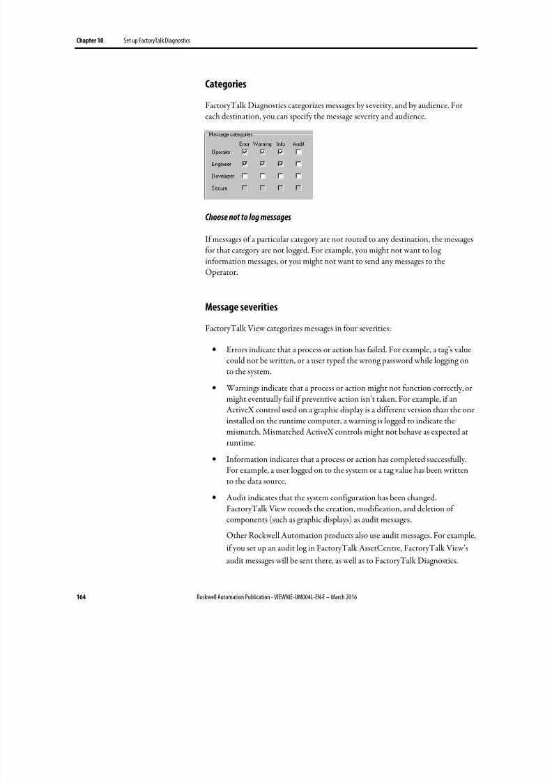
8/17/2019 FactoryTalk® View Machine Edition User's Guide
http://slidepdf.com/reader/full/factorytalk-view-machine-edition-users-guide 164/587
Chapter 10 Set up FactoryTalk Diagnostics
164 Rockwell Automation Publication - VIEWME-UM004L-EN-E – March 2016
Categories
FactoryTalk Diagnostics categorizes messages by severity, and by audience. For
each destination, you can specify the message severity and audience.
Choose not to log messages
If messages of a particular category are not routed to any destination, the messagesfor that category are not logged. For example, you might not want to loginformation messages, or you might not want to send any messages to theOperator.
Message severities
FactoryTalk View categorizes messages in four severities:
• Errors indicate that a process or action has failed. For example, a tag’s value
could not be written, or a user typed the wrong password while logging onto the system.
• Warnings indicate that a process or action might not function correctly, ormight eventually fail if preventive action isn’t taken. For example, if anActiveX control used on a graphic display is a different version than the oneinstalled on the runtime computer, a warning is logged to indicate themismatch. Mismatched ActiveX controls might not behave as expected atruntime.
• Information indicates that a process or action has completed successfully.For example, a user logged on to the system or a tag value has been written
to the data source.• Audit indicates that the system configuration has been changed.
FactoryTalk View records the creation, modification, and deletion ofcomponents (such as graphic displays) as audit messages.
Other Rockwell Automation products also use audit messages. For example,
if you set up an audit log in FactoryTalk AssetCentre, FactoryTalk View’s
audit messages will be sent there, as well as to FactoryTalk Diagnostics.
8/17/2019 FactoryTalk® View Machine Edition User's Guide
http://slidepdf.com/reader/full/factorytalk-view-machine-edition-users-guide 165/587
Set up FactoryTalk Diagnostics Chapter 10
Rockwell Automation Publication - VIEWME-UM004L-EN-E – March 2016 165
In the FactoryTalk Diagnostics Viewer, the message severity is shown in theSeverity column, indicated by the ! symbol.
The content of the messages is provided by the system. You do not need to do
anything to set up message content.
Audiences
FactoryTalk Diagnostics allows messages to be categorized differently for the various people for whom the messages are relevant. You can sort the messages inthe FactoryTalk Diagnostics Viewer, so that those relevant to a particular personare grouped together.
Who receives which messages?
You can specify which types of messages are sent to the Operator, Engineer, andDeveloper audiences.
FactoryTalk View automatically sends audit messages to the Engineer and Secureaudiences. Audit messages allow auditing tools, such as those required for USGovernment 21CFR Part 11 compliance, to track system activity.
During application development, diagnostics messages are shown as you create,modify, and delete components, and when you test your graphic displays. Themessages are shown in the Diagnostics List at the bottom of the FactoryTalk
View Studio window. You can also view the messages in the FactoryTalkDiagnostics Viewer, as described in the next section.
By default, all warning and error messages are shown in the Diagnostics List. Tochange what is shown in the Diagnostics List, use the Diagnostics Setup tool, asdescribed on Use the Diagnostics Setup tool on page 166.
For information about testing graphic displays, see Test your displays as you work on page 311.
To show the Diagnostics List
• From the View menu, select Diagnostics List. A check mark beside themenu item indicates the Diagnostics List is shown.
For information about moving, resizing, and clearing messages in the Diagnostics
List, see The Diagnostics List on page 43.
Show diagnostics messages
during application
development
8/17/2019 FactoryTalk® View Machine Edition User's Guide
http://slidepdf.com/reader/full/factorytalk-view-machine-edition-users-guide 166/587
Chapter 10 Set up FactoryTalk Diagnostics
166 Rockwell Automation Publication - VIEWME-UM004L-EN-E – March 2016
If you don’t want to show diagnostics messages
From the View menu, select Diagnostics List. The option is turned off when no
check mark appears.
Use the FactoryTalk Diagnostics Viewer tool to view the contents of FactoryTalkDiagnostics local log files. You can open the FactoryTalk Diagnostics Viewer from within FactoryTalk View Studio or from Windows Start menu.
The FactoryTalk Diagnostics Viewer is available on personal computers.
You can also set up personal computers to accept messages from a MobileView,PanelView Plus 7, PanelView Plus 6, PanelView Plus, PanelView Plus Compact, orPanelView Plus CE terminal, and then show the messages in the FactoryTalkDiagnostics Viewer or in the Diagnostics List. For information about sending
messages from a MobileView, PanelView Plus 7, PanelView Plus 6, PanelViewPlus, PanelView Plus Compact, or PanelView Plus CE terminal to personalcomputers, see Receive messages from a MobileView, PanelView Plus 7, PanelViewPlus 6, PanelView Plus, PanelView Plus Compact, or PanelView Plus CE terminal on page 168.
To open the FactoryTalk Diagnostics Viewer, do one of the following
• In FactoryTalk View Studio, from the Tools menu, select Diagnostics
Viewer .
• From Windows Start menu, select Programs > Rockwell Software >
FactoryTalk Tools > Diagnostics Viewer .
For information about setting up FactoryTalk Diagnostics to send messages to thelocal log, see Help for the Diagnostics Setup tool. For additional informationabout setting up and using the FactoryTalk Diagnostics Viewer, see theFactoryTalk Diagnostics Viewer Help.
Use the Diagnostics Setup tool to set up:
• Destinations and message routing on the development computer, including
logging to the local log or to an ODBC database.
• Destinations and message routing on personal computers, includingruntime logging to the local log or to an ODBC database.
• The Windows CE runtime destination to receive logged messages from.
You can also use the Diagnostics Setup tool to clear the local log file.
View FactoryTalk
Diagnostics log files
Use the Diagnostics Setup
tool
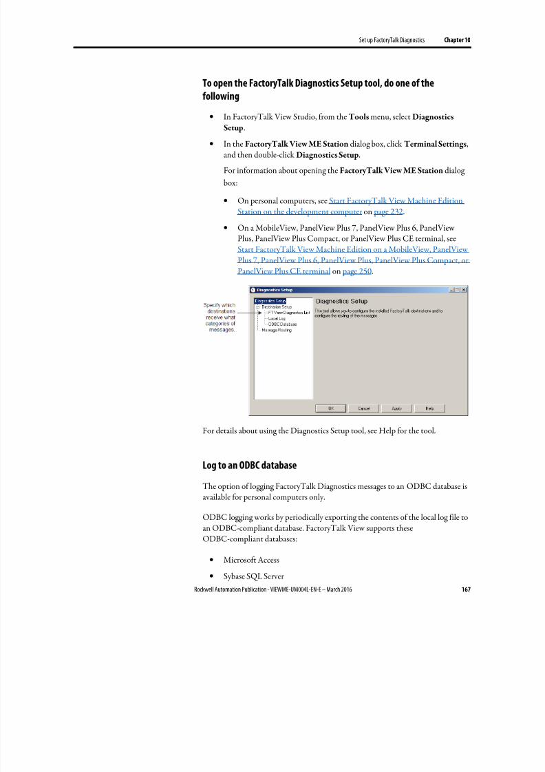
8/17/2019 FactoryTalk® View Machine Edition User's Guide
http://slidepdf.com/reader/full/factorytalk-view-machine-edition-users-guide 167/587
Set up FactoryTalk Diagnostics Chapter 10
Rockwell Automation Publication - VIEWME-UM004L-EN-E – March 2016 167
To open the FactoryTalk Diagnostics Setup tool, do one of the
following
•
In FactoryTalk View Studio, from the Tools menu, select DiagnosticsSetup.
• In the FactoryTalk View ME Station dialog box, click Terminal Settings,and then double-click Diagnostics Setup.
For information about opening the FactoryTalk View ME Station dialog
box:
• On personal computers, see Start FactoryTalk View Machine EditionStation on the development computer on page 232.
• On a MobileView, PanelView Plus 7, PanelView Plus 6, PanelView
Plus, PanelView Plus Compact, or PanelView Plus CE terminal, seeStart FactoryTalk View Machine Edition on a MobileView, PanelViewPlus 7, PanelView Plus 6, PanelView Plus, PanelView Plus Compact, orPanelView Plus CE terminal on page 250.
For details about using the Diagnostics Setup tool, see Help for the tool.
Log to an ODBC database
The option of logging FactoryTalk Diagnostics messages to an ODBC database isavailable for personal computers only.
ODBC logging works by periodically exporting the contents of the local log file toan ODBC-compliant database. FactoryTalk View supports theseODBC-compliant databases:
• Microsoft Access
• Sybase SQL Server
8/17/2019 FactoryTalk® View Machine Edition User's Guide
http://slidepdf.com/reader/full/factorytalk-view-machine-edition-users-guide 168/587
Chapter 10 Set up FactoryTalk Diagnostics
168 Rockwell Automation Publication - VIEWME-UM004L-EN-E – March 2016
• Oracle
• Microsoft SQL Server
If you have set up FactoryTalk Diagnostics to overwrite events in the local log file,make sure messages are logged to the ODBC-compliant database before the oldestevents are deleted.
For information about the contents of the FactoryTalk Diagnostics ODBC tables,see ODBC database schema on page 551.
Set up message buffering
FactoryTalk Diagnostics messages are stored in the computer’s local log file, andare exported to the ODBC-compliant database at the interval you specify.
You can also specify that messages remain in the local log file for a period of timeafter they have been exported to the ODBC-compliant database. This is useful inthe event of a network failure, or any other reason that causes the database to beunavailable. In this case, the messages remain in the local log file until the buffertime expires. If the ODBC-compliant database becomes available during thattime, the buffered messages are then exported to the database.
Route messages
For each destination you set up, you can specify how messages are routed.
To route messages
You need specify:
• The types of messages to log
• The audiences to send the messages to
• Whether to accept messages from Windows CE devices
For information about who receives which types of messages, see Who receives which messages? on page 165.
Receive messages from a MobileView, PanelView Plus 7, PanelView
Plus 6, PanelView Plus, PanelView Plus Compact, or PanelView Plus CE
terminal
You can set up FactoryTalk Diagnostics to receive messages that are generated onthe MobileView, PanelView Plus 7, PanelView Plus 6, PanelView Plus, PanelView
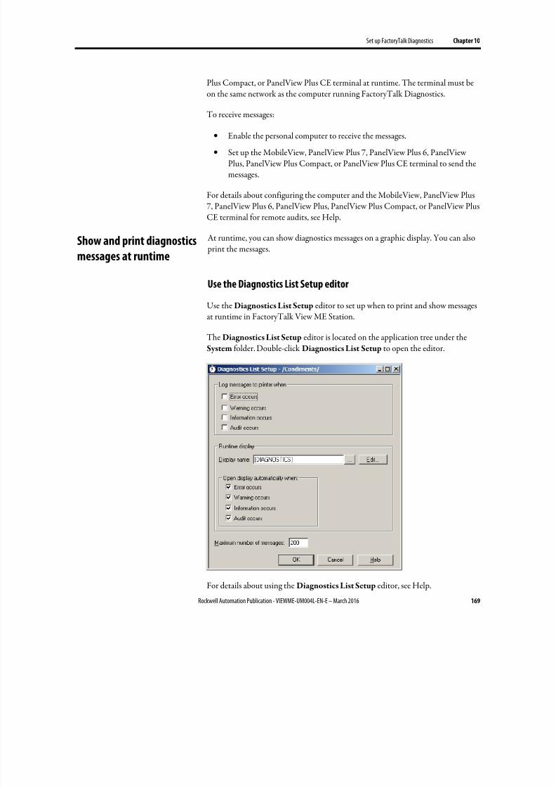
8/17/2019 FactoryTalk® View Machine Edition User's Guide
http://slidepdf.com/reader/full/factorytalk-view-machine-edition-users-guide 169/587
Set up FactoryTalk Diagnostics Chapter 10
Rockwell Automation Publication - VIEWME-UM004L-EN-E – March 2016 169
Plus Compact, or PanelView Plus CE terminal at runtime. The terminal must beon the same network as the computer running FactoryTalk Diagnostics.
To receive messages:
• Enable the personal computer to receive the messages.
• Set up the MobileView, PanelView Plus 7, PanelView Plus 6, PanelViewPlus, PanelView Plus Compact, or PanelView Plus CE terminal to send themessages.
For details about configuring the computer and the MobileView, PanelView Plus7, PanelView Plus 6, PanelView Plus, PanelView Plus Compact, or PanelView PlusCE terminal for remote audits, see Help.
At runtime, you can show diagnostics messages on a graphic display. You can also print the messages.
Use the Diagnostics List Setup editor
Use the Diagnostics List Setup editor to set up when to print and show messagesat runtime in FactoryTalk View ME Station.
The Diagnostics List Setup editor is located on the application tree under theSystem folder. Double-click Diagnostics List Setup to open the editor.
For details about using the Diagnostics List Setup editor, see Help.
Show and print diagnosticsmessages at runtime
8/17/2019 FactoryTalk® View Machine Edition User's Guide
http://slidepdf.com/reader/full/factorytalk-view-machine-edition-users-guide 170/587
Chapter 10 Set up FactoryTalk Diagnostics
170 Rockwell Automation Publication - VIEWME-UM004L-EN-E – March 2016
Printed messages list the date and time, the category of system activity, and themessage text. By default, messages are not printed at runtime.
By default, your application is set up to show diagnostics messages automatically at
runtime. If you want to use the default settings, you don’t need to do anythingfurther to set up diagnostics messages for print and display in FactoryTalk ViewME Station.
The messages that are printed and shown depend on how you set up FactoryTalkDiagnostics on the runtime computer:
• For applications running on personal computers, use the Diagnostics Setuptool to set up diagnostics message logging. For information about using theDiagnostics Setup tool, see Help.
•
For information about setting up FactoryTalk Diagnostics on theMobileView, PanelView Plus 7, PanelView Plus 6, PanelView Plus,PanelView Plus Compact, or PanelView Plus CE terminal, see Help.
For applications running on personal computers, you can also view the runtimemessages in the FactoryTalk Diagnostics Viewer as described on View FactoryTalkDiagnostics log files on page 166.
If you don’t want to show diagnostics messages in FactoryTalk View ME Station
In FactoryTalk View Studio, in the Diagnostics List Setup editor, clear theDisplay name box, or clear the four Open display automatically when boxes.
Set up how messages are shown and printed at runtime
Follow these steps to set up how diagnostics messages are shown at runtime:
1. In FactoryTalk View Studio, in the Diagnostics List Setup editor, specify which messages to print, the graphic display to use, when to open thegraphic display, and the maximum number of messages to store.
2. If desired, modify the default [DIAGNOSTICS] display, or create your
own graphic display to use for diagnostics messages. For example, if youdon’t want the operator to clear all messages at once, edit the default displayto remove the clear all button.
For information about graphic displays, see Use graphic displays on page
303.
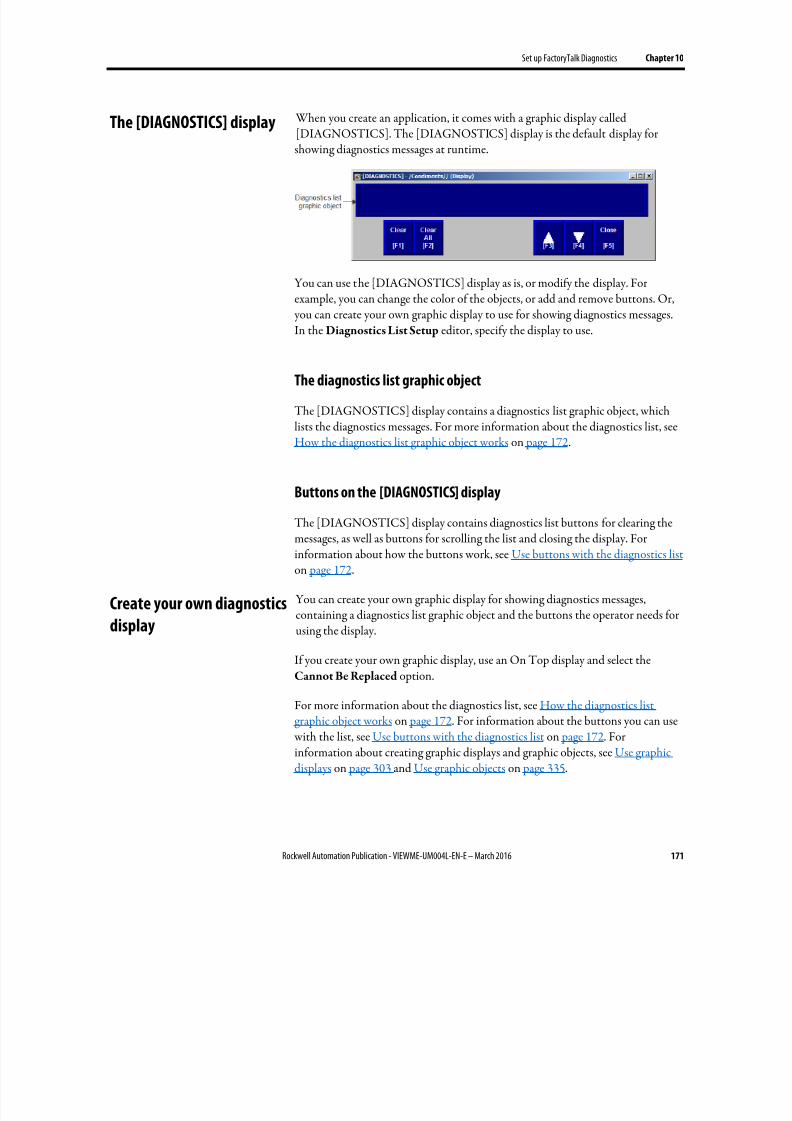
8/17/2019 FactoryTalk® View Machine Edition User's Guide
http://slidepdf.com/reader/full/factorytalk-view-machine-edition-users-guide 171/587
Set up FactoryTalk Diagnostics Chapter 10
Rockwell Automation Publication - VIEWME-UM004L-EN-E – March 2016 171
When you create an application, it comes with a graphic display called[DIAGNOSTICS]. The [DIAGNOSTICS] display is the default display forshowing diagnostics messages at runtime.
You can use the [DIAGNOSTICS] display as is, or modify the display. Forexample, you can change the color of the objects, or add and remove buttons. Or, you can create your own graphic display to use for showing diagnostics messages.In the Diagnostics List Setup editor, specify the display to use.
The diagnostics list graphic object
The [DIAGNOSTICS] display contains a diagnostics list graphic object, whichlists the diagnostics messages. For more information about the diagnostics list, seeHow the diagnostics list graphic object works on page 172.
Buttons on the [DIAGNOSTICS] display
The [DIAGNOSTICS] display contains diagnostics list buttons for clearing themessages, as well as buttons for scrolling the list and closing the display. Forinformation about how the buttons work, see Use buttons with the diagnostics list on page 172.
You can create your own graphic display for showing diagnostics messages,containing a diagnostics list graphic object and the buttons the operator needs forusing the display.
If you create your own graphic display, use an On Top display and select theCannot Be Replaced option.
For more information about the diagnostics list, see How the diagnostics listgraphic object works on page 172. For information about the buttons you can use with the list, see Use buttons with the diagnostics list on page 172. Forinformation about creating graphic displays and graphic objects, see Use graphicdisplays on page 303 and Use graphic objects on page 335.
The [DIAGNOSTICS] display
Create your own diagnostics
display
8/17/2019 FactoryTalk® View Machine Edition User's Guide
http://slidepdf.com/reader/full/factorytalk-view-machine-edition-users-guide 172/587
Chapter 10 Set up FactoryTalk Diagnostics
172 Rockwell Automation Publication - VIEWME-UM004L-EN-E – March 2016
Open the display
The diagnostics display you specify in the Diagnostics List Setup editor (either
the default [DIAGNOSTICS] display or a display you create) is automaticallyopened whenever a diagnostics message of the specified severity occurs.
The display remains open until the operator closes the display.
If you decide not to open the diagnostics display automatically, you can create aGoto display button that the operator can press to open the diagnostics display.For information about setting up a Goto display button and specifying the displayto open, see Help.
Close the display
The operator can close the display by pressing a close display button.
At runtime, when a severity of system activity occurs that you set up to log, amessage about the activity is added to the diagnostics list. The diagnostics list canbe in the [DIAGNOSTICS] display, in a diagnostics display you have created, orcan be placed on any display in your application.
You can use multiple diagnostics lists, in the same display or in different displays.Each diagnostics list shows the same information.
For information about setting up diagnostics lists, see Help.
What is shown
• If the message is too long to fit in the list, the last shown character isreplaced with an asterisk (*).
• The number of diagnostics messages that is visible at one time depends onthe height of the diagnostics list and the list’s font size.
• Messages are listed with the newest diagnostics message on top.
Use buttons with the diagnostics list
Diagnostics buttons
You can use these diagnostics buttons to interact with the diagnostics list:
Open and close the
diagnostics display
How the diagnostics list
graphic object works
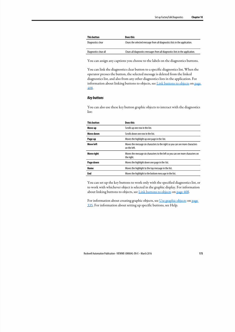
8/17/2019 FactoryTalk® View Machine Edition User's Guide
http://slidepdf.com/reader/full/factorytalk-view-machine-edition-users-guide 173/587
Set up FactoryTalk Diagnostics Chapter 10
Rockwell Automation Publication - VIEWME-UM004L-EN-E – March 2016 173
This button Does this
Diagnostics clear Clears the selected message from all diagnostics lists in the application.
Diagnostics clear all Clears all diagnostics messages from all diagnostics lists in the application.
You can assign any captions you choose to the labels on the diagnostics buttons.
You can link the diagnostics clear button to a specific diagnostics list. When theoperator presses the button, the selected message is deleted from the linkeddiagnostics list, and also from any other diagnostics lists in the application. Forinformation about linking buttons to objects, see Link buttons to objects on page408.
Key buttons
You can also use these key button graphic objects to interact with the diagnosticslist:
This button Does this
Move up Scrolls up one row in the list.
Move down Scrolls down one row in the list.
Page up Moves the highlight up one page in the list.
Move left Moves the message six characters to the right so you can see more characterson the left.
Move right Moves the message six characters to the left so you can see more characters onthe right.
Page down Moves the highlight down one page in the list.
Home Moves the highlight to the top message in the list.
End Moves the highlight to the bottom mess age in the list.
You can set up the key buttons to work only with the specified diagnostics list, orto work with whichever object is selected in the graphic display. For informationabout linking buttons to objects, see Link buttons to objects on page 408.
For information about creating graphic objects, see Use graphic objects on page
335. For information about setting up specific buttons, see Help.

8/17/2019 FactoryTalk® View Machine Edition User's Guide
http://slidepdf.com/reader/full/factorytalk-view-machine-edition-users-guide 174/587
Chapter 10 Set up FactoryTalk Diagnostics
174 Rockwell Automation Publication - VIEWME-UM004L-EN-E – March 2016
8/17/2019 FactoryTalk® View Machine Edition User's Guide
http://slidepdf.com/reader/full/factorytalk-view-machine-edition-users-guide 175/587
Rockwell Automation Publication - VIEWME-UM004L-EN-E – March 2016 175
Chapter 11
Set up security
This chapter describes:
• Use FactoryTalk Security to add users and groups accounts
• Use the Runtime Security editor
• Configure displays to control runtime operator access
•
Provide a way for users to log in and log out• Set up FactoryTalk Security in FactoryTalk View Studio
• Configure user accounts policies
• Examples of how to configure applications to use FactoryTalk View securityfeatures
FactoryTalk View and FactoryTalk Security work together to provide secureaccess to applications during development and at runtime. FactoryTalk Security isinstalled as part of the FactoryTalk Services Platform, and uses FactoryTalkDirectory to manage user accounts and policies.
Starting with FactoryTalk View ME 8.00.00, FactoryTalk security applies to theopen application only. Users and groups are saved with the project and are notshared with other projects.
You can use a combination of FactoryTalk Security and FactoryTalk View securityfeatures at runtime to:
• Prevent unauthorized users from running the application.
• Prevent users from opening graphic displays.
•
Prevent unauthorized users from stopping the application.• Prevent users from seeing and using certain parts of a graphic display.
• Prevent users from switching to other applications. This feature uses theDeskLock tool, and is available for personal computers only. You can usethis tool to set up a customized desktop and to prevent access to Windowsfunctions. For more information about the DeskLock tool, see Runapplications on a personal computer on page 229. The DeskLock tool doesnot use FactoryTalk Security.
Use security with your
application
8/17/2019 FactoryTalk® View Machine Edition User's Guide
http://slidepdf.com/reader/full/factorytalk-view-machine-edition-users-guide 176/587
Chapter 11 Set up security
176 Rockwell Automation Publication - VIEWME-UM004L-EN-E – March 2016
To limit the users who have access to the application or parts of the application, you must set up user accounts and passwords.
If you set up the data source to open graphic displays remotely (using global
connections), remote display changes occur whether or not the logged-in user hassecurity access to a given display.
For details about controlling display changes remotely, see Control display changesremotely on page 114.
Tip: The Authenticated User group is not supported on Windows CE. On Windows CE terminals,Windows-linked users must be added to FactoryTalk Directory before they can be loggedin.
If you do not create additional FactoryTalk View user accounts
FactoryTalk View creates a user named DEFAULT, and this user is automaticallylogged in when you start applications at runtime. You do not need to set up anyother users, and users do not need to log in to use the applications you create.
If you use FactoryTalk View user accounts
If you want to use FactoryTalk View user accounts, for example, to run login andlogout macros, follow these steps.
1. Add users or user groups to FactoryTalk Security.
2. Add the FactoryTalk Security users or user groups to the FactoryTalk View
Runtime Security editor. For details, see To add FactoryTalk Security usersand groups to FactoryTalk View and assign security codes to them on page180.
3. In the FactoryTalk View Runtime Security editor, if desired, assign loginand logout macros and security codes to users or user groups. For details, see
Help for the editor.
4. In the Graphics editor, assign security codes to graphic displays that willhave limited access. An alternative is to use object animation to control visibility based on the logged in user’s FactoryTalk View Runtime
Security security codes.
5.
Provide users with a method for logging in and out.
These steps are described in detail in this chapter.
8/17/2019 FactoryTalk® View Machine Edition User's Guide
http://slidepdf.com/reader/full/factorytalk-view-machine-edition-users-guide 177/587
Set up security Chapter 11
Rockwell Automation Publication - VIEWME-UM004L-EN-E – March 2016 177
Follow these steps to set up security using FactoryTalk Security and FactoryTalk View security features:
1.
In the Explorer window, in the System folder underneath the HMI server,
add FactoryTalk Security user groups and users, and set up their passwords.
You can also add users and groups in the Runtime Security editor, on the
ME Runtime 4.00 and later tab, as described in To add FactoryTalk
Security users and groups to FactoryTalk View and assign security codes to
them on page 180.
2. In the Runtime Security editor, add FactoryTalk Security users or usergroups to FactoryTalk View, and assign login and logout macros andsecurity codes to them.
3.
In the Graphics editor, assign security codes to graphic displays that willhave limited access.
4.
Provide users with a method for logging in and out.
5.
If desired, prevent unauthorized users from stopping the application.
6.
Set up policies for passwords and user accounts.
These steps are described in details in the following sections.
You can also assign security to action groups, connections, and databases. Thesetopics are not discussed in this chapter. For information about these topics, see theFactoryTalk Security Help.
Create FactoryTalk Security users
You can set up users in FactoryTalk Security before you add them to theFactoryTalk View Runtime Security editor.
FactoryTalk Security allows you to reference user accounts that have already been
set up in Windows. These are called Windows-linked users. The link symbol inthe Explorer window indicates that a user is a Windows-linked user.
To set up users
1.
In the System folder, right-click Users and select New User or New
Windows-Linked User.
2.
Specify the user name, password, and password options. For details, seeHelp.
Steps for setting up security
8/17/2019 FactoryTalk® View Machine Edition User's Guide
http://slidepdf.com/reader/full/factorytalk-view-machine-edition-users-guide 178/587
Chapter 11 Set up security
178 Rockwell Automation Publication - VIEWME-UM004L-EN-E – March 2016
3. To add users to a group, right-click the group and select Properties. Fordetails, see Help.
To change user passwords
1. In the Users folder, right-click the user name and select Properties.
2. Click Reset Password. For details, see Help.
Users can change their password at runtime using the Password button. For moreinformation, see Change passwords on page 264.
Users can also change their properties at runtime using the Change User
Properties button. For more information, see Change User Properties on page276.
Create FactoryTalk Security user groups
The use of user groups is optional but recommended. Groups allow you to set upsecurity access once for the entire group, rather than individually for members ofthe group. You can still set up separate permissions for individual members of thegroup.
Tip: Setting up groups saves time. You can add all the users of an application to a single groupin FactoryTalk Security, then add the group to the FactoryTalk View Runtime
Securityeditor in one step, which is much quicker than adding the users one by one.
FactoryTalk Security allows you to use groups that have already been set up in Windows. These are called Windows-linked groups. The link symbol in theExplorer window indicates that a group is a Windows-linked group.
FactoryTalk Security comes with an Administrators group already set up. Thelocal computers Windows Administrators group is automatically added to thisFactoryTalk Security group. To start with, members of this group have fullsecurity access to FactoryTalk Security , and therefore have full access to yourapplications.
To ensure that you are never locked out of FactoryTalk Directory we recommendthat you assign more than one user to the Administrators group. If one user islocked out, you can use the other one to log in.
To set up user groups
1. In the System folder, right-click User Groups and select New User Group or New Windows-Linked User Group.

8/17/2019 FactoryTalk® View Machine Edition User's Guide
http://slidepdf.com/reader/full/factorytalk-view-machine-edition-users-guide 179/587
Set up security Chapter 11
Rockwell Automation Publication - VIEWME-UM004L-EN-E – March 2016 179
2. Add user groups. You can add members to the groups now or later. Fordetails, see Help.
3. To add members to the group later, right-click the group and selectProperties. For details, see Help.
To add user accounts to the group
1. In the System/Users and Groups/User Groups folder, double-click a usergroup.
2.
In the Properties dialog box, click Add.
3. In the Select User or Group dialog box, select the user accounts you wan tobe members of the group and click OK .
Use the Runtime Security editor to:
• Add FactoryTalk Security users and assign security codes and login andlogout macros, for each user or group of users that will have access to theapplication at runtime.
• Migrate users from RSView version 3.20 and earlier to FactoryTalk View version 4.00 or later.
• Assign user passwords (version 3.20 and earlier applications only).
• Add Windows users or groups (version 3.20 and earlier applications only).
The method for adding users and assigning security codes to them depends on whether you are setting up users for FactoryTalk View 4.00 applications or forRSView 3.20 and earlier applications. There is a separate tab for 4.00 and laterapplications and for 3.20 and earlier applications.
The Runtime Security editor has special items on the View menu to control theappearance of the editor. It also has items on the Setup menu, and extra tools onthe toolbar.
When you assign a security code to a graphic display, only the users and groups
who are assigned that security code have access to the display. There are 16security codes, A through P.
The asterisk symbol (*) is used in displays and represents any code. Users musthave at least one code assigned to open displays that use the * code.
You can assign combinations of security codes to users and groups, to allow eachuser or group access to a different set of displays or graphic objects.
Work with the Runtime
Security editor
How user accounts and
security codes work
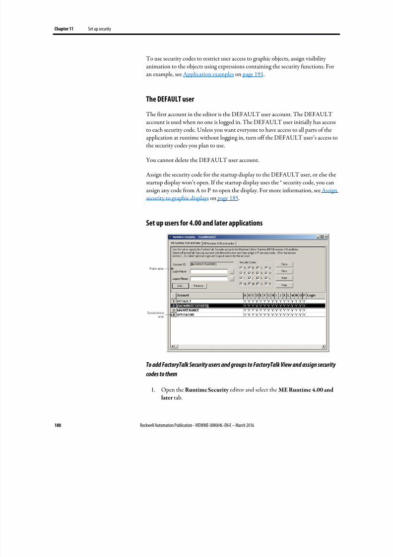
8/17/2019 FactoryTalk® View Machine Edition User's Guide
http://slidepdf.com/reader/full/factorytalk-view-machine-edition-users-guide 180/587
Chapter 11 Set up security
180 Rockwell Automation Publication - VIEWME-UM004L-EN-E – March 2016
To use security codes to restrict user access to graphic objects, assign visibilityanimation to the objects using expressions containing the security functions. Foran example, see Application examples on page 191.
The DEFAULT user
The first account in the editor is the DEFAULT user account. The DEFAULTaccount is used when no one is logged in. The DEFAULT user initially has accessto each security code. Unless you want everyone to have access to all parts of theapplication at runtime without logging in, turn off the DEFAULT user’s access tothe security codes you plan to use.
You cannot delete the DEFAULT user account.
Assign the security code for the startup display to the DEFAULT user, or else thestartup display won’t open. If the startup display uses the * security code, you canassign any code from A to P to open the display. For more information, see Assignsecurity to graphic displays on page 185.
Set up users for 4.00 and later applications
To add FactoryTalk Security users and groups to FactoryTalk View and assign security
codes to them
1. Open the Runtime Security editor and select the ME Runtime 4.00 and
later tab.
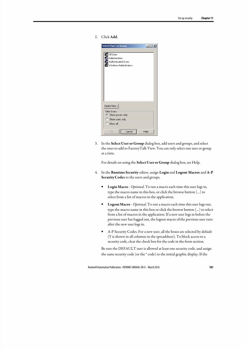
8/17/2019 FactoryTalk® View Machine Edition User's Guide
http://slidepdf.com/reader/full/factorytalk-view-machine-edition-users-guide 181/587
Set up security Chapter 11
Rockwell Automation Publication - VIEWME-UM004L-EN-E – March 2016 181
2. Click Add.
3. In the Select User or Group dialog box, add users and groups, and selectthe ones to add to FactoryTalk View. You can only select one user or groupat a time.
For details on using the Select User or Group dialog box, see Help.
4. In the Runtime Security editor, assign Login and Logout Macros and A-PSecurity Codes to the users and groups.
• Login Macro - Optional . To run a macro each time this user logs in,
type the macro name in this box, or click the browse button (…) toselect from a list of macros in the application.
• Logout Macro - Optional . To run a macro each time this user logs out,
type the macro name in this box or click the browse button (…) to selectfrom a list of macros in the application. If a new user logs in before the previous user has logged out, the logout macro of the previous user runsafter the new user logs in.
• A-P Security Codes. For a new user, all the boxes are selected by default(Y is shown in all columns in the spreadsheet). To block access to asecurity code, clear the check box for the code in the form section.
Be sure the DEFAULT user is allowed at least one security code, and assign
the same security code (or the * code) to the initial graphic display. If the
8/17/2019 FactoryTalk® View Machine Edition User's Guide
http://slidepdf.com/reader/full/factorytalk-view-machine-edition-users-guide 182/587
Chapter 11 Set up security
182 Rockwell Automation Publication - VIEWME-UM004L-EN-E – March 2016
DEFAULT user has no security codes allowed, when the application is run,
no display will open.
To remove a FactoryTalk Security user or group from FactoryTalk View
1. Open the Runtime Security editor and select the ME Runtime 4.00 and
later tab.
2. In the Account column, select a user or group, and click Remove.
3. Click Yes.
To migrate RSView 3.20 and earlier users to FactoryTalk View
1. With the Runtime Security editor open and the ME Runtime 4.00 and
later tab selected, from the Setup menu, select Migrate ME Runtime 3.20and earlier accounts.
Users from the ME Runtime 3.20 and earlier tab are added to the
FactoryTalk Security Users folder and to the ME Runtime 4.00 and later
tab.
Tip: Users are not migrated if they already exist in the ME Runtime 4.00 and later account list.
2. If desired, edit the users’ security codes and login and logout macros.
3. If desired, edit the users' passwords.
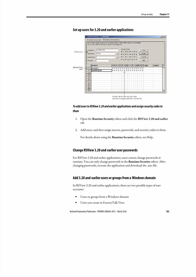
8/17/2019 FactoryTalk® View Machine Edition User's Guide
http://slidepdf.com/reader/full/factorytalk-view-machine-edition-users-guide 183/587
Set up security Chapter 11
Rockwell Automation Publication - VIEWME-UM004L-EN-E – March 2016 183
Set up users for 3.20 and earlier applications
To add users to RSView 3.20 and earlier applications and assign security codes to
them
1. Open the Runtime Security editor and click the RSView 3.20 and earliertab.
2.
Add users, and then assign macros, passwords, and security codes to them.
For details about using the Runtime Security editor, see Help.
Change RSView 3.20 and earlier user passwords
For RSView 3.20 and earlier applications, users cannot change passwords atruntime. You can only change passwords in the Runtime Security editor. Afterchanging passwords, recreate the application and download the .mer file.
Add 3.20 and earlier users or groups from a Windows domain
In RSView 3.20 and earlier applications, there are two possible types of useraccounts:
• Users or groups from a Windows domain
• Users you create in FactoryTalk View.
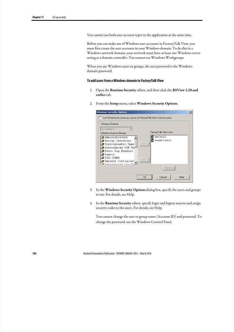
8/17/2019 FactoryTalk® View Machine Edition User's Guide
http://slidepdf.com/reader/full/factorytalk-view-machine-edition-users-guide 184/587
Chapter 11 Set up security
184 Rockwell Automation Publication - VIEWME-UM004L-EN-E – March 2016
You cannot use both user account types in the application at the same time.
Before you can make use of Windows user accounts in FactoryTalk View, youmust first create the user accounts in your Windows domain. To do this in a
Windows network domain, your network must have at least one Windows serveracting as a domain controller. You cannot use Windows Workgroups.
When you use Windows users or groups, the user password is the Windowsdomain password.
To add users from a Windows domain to FactoryTalk View
1. Open the Runtime Security editor, and then click the RSView 3.20 and
earlier tab.
2.
From the Setup menu, select Windows Security Options.
3. In the Windows Security Options dialog box, specify the users and groupsto use. For details, see Help.
4. In the Runtime Security editor, specify login and logout macros and assignsecurity codes to the users. For details, see Help.
You cannot change the user or group name (Account ID) and password. To
change the password, use the Windows Control Panel.
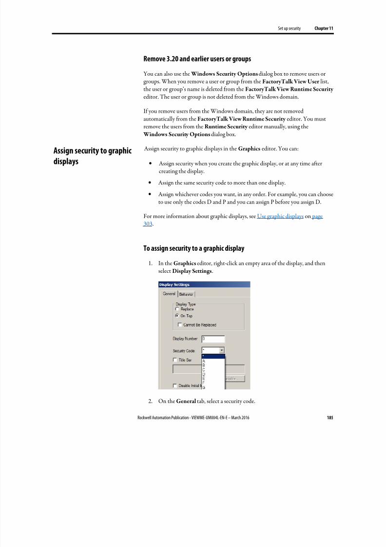
8/17/2019 FactoryTalk® View Machine Edition User's Guide
http://slidepdf.com/reader/full/factorytalk-view-machine-edition-users-guide 185/587
Set up security Chapter 11
Rockwell Automation Publication - VIEWME-UM004L-EN-E – March 2016 185
Remove 3.20 and earlier users or groups
You can also use the Windows Security Options dialog box to remove users or
groups. When you remove a user or group from the FactoryTalk View User list,the user or group’s name is deleted from the FactoryTalk View Runtime Security editor. The user or group is not deleted from the Windows domain.
If you remove users from the Windows domain, they are not removedautomatically from the FactoryTalk View Runtime Security editor. You mustremove the users from the Runtime Security editor manually, using the
Windows Security Options dialog box.
Assign security to graphic displays in the Graphics editor. You can:
• Assign security when you create the graphic display, or at any time after
creating the display.
• Assign the same security code to more than one display.
• Assign whichever codes you want, in any order. For example, you can chooseto use only the codes D and P and you can assign P before you assign D.
For more information about graphic displays, see Use graphic displays on page303.
To assign security to a graphic display
1. In the Graphics editor, right-click an empty area of the display, and thenselect Display Settings.
2. On the General tab, select a security code.
Assign security to graphic
displays

8/17/2019 FactoryTalk® View Machine Edition User's Guide
http://slidepdf.com/reader/full/factorytalk-view-machine-edition-users-guide 186/587
Chapter 11 Set up security
186 Rockwell Automation Publication - VIEWME-UM004L-EN-E – March 2016
3. To give every security code access to the display, select the asterisk (*). The *is selected by default.
Use Login and Logout buttons to provide a way for users to log in and log out.
Make sure you place these buttons in graphic displays that all users have access to.
Log in
When the application starts, the DEFAULT user is logged in. If a macro isassigned to the DEFAULT user, the macro runs.
For example, you could create a macro to set the remote display number to open anew login display after the DEFAULT user logs in. For information aboutcontrolling display changes remotely, see Control display changes remotely on
page 114. Remote display changes are not checked for security.
To provide a way for users to log in
1. Specify the startup display in the Startup editor, in the Initial graphic box.The startup display is the graphic display that opens when your applicationstarts running.
2. The startup display must have the * code or a security code that is assignedto the DEFAULT user, or it will not open.
For information about the Startup editor, see Create runtime applications on page 223.
3. Create a Login button in the startup display.
For information about creating graphic objects, see Use graphic objects on
page 335. For information about setting up Login buttons, see Help.
For more information about logging in, see Use your application on page 255.
Log out
When the current user logs out, if a logout macro is assigned to the user, the macroruns. If the user belongs to a group, and a logout macro is set up for the group, thelogout macro runs.
After the current user is logged out, the DEFAULT user is logged in. If a loginmacro is assigned to the DEFAULT user, the macro runs.
Provide a way for users tolog in and log out
8/17/2019 FactoryTalk® View Machine Edition User's Guide
http://slidepdf.com/reader/full/factorytalk-view-machine-edition-users-guide 187/587
Set up security Chapter 11
Rockwell Automation Publication - VIEWME-UM004L-EN-E – March 2016 187
You can also set up the application to automatically log out the current user after aspecified period of inactivity. For more information, see Log out automatically on page 187.
To provide a way for users to log out
• Create a Logout button on a graphic display that all logged-in users haveaccess to.
Log out automatically
You can set up your runtime terminal to log out the current user automaticallyafter the terminal has been inactive for a specified period of time.
At runtime, when the inactivity period expires:
• The current user is logged out
• Any logout macros assigned to the current user, or user group in RuntimeSecurity execute
• The DEFAULT user is logged in
• The login macro assigned to the DEFAULT user executes
• The specified graphic display opens
•
The display Startup and Shutdown macros execute
The automatic logout is independent of FactoryTalk Security settings or Windows security settings. The logout occurs regardless of what you set up inFactoryTalk Security, or Windows.
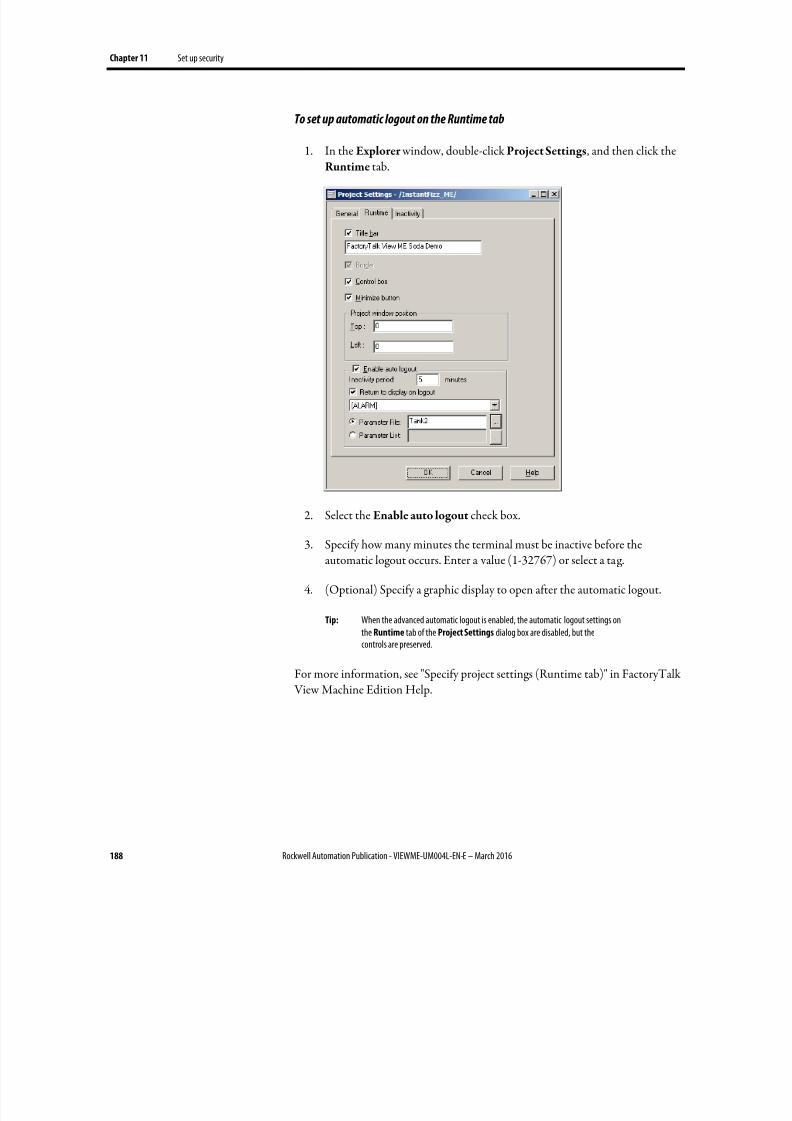
8/17/2019 FactoryTalk® View Machine Edition User's Guide
http://slidepdf.com/reader/full/factorytalk-view-machine-edition-users-guide 188/587
Chapter 11 Set up security
188 Rockwell Automation Publication - VIEWME-UM004L-EN-E – March 2016
To set up automatic logout on the Runtime tab
1. In the Explorer window, double-click Project Settings, and then click theRuntime
tab.
2.
Select the Enable auto logout check box.
3. Specify how many minutes the terminal must be inactive before theautomatic logout occurs. Enter a value (1-32767) or select a tag.
4. (Optional) Specify a graphic display to open after the automatic logout.
Tip: When the advanced automatic logout is enabled, the automatic logout settings onthe Runtime tab of the Project Settings dialog box are disabled, but thecontrols are preserved.
For more information, see "Specify project settings (Runtime tab)" in FactoryTalk
View Machine Edition Help.
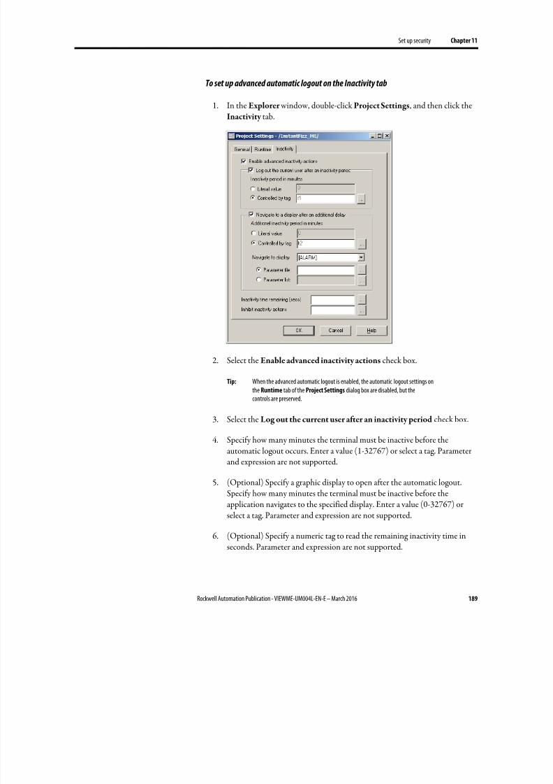
8/17/2019 FactoryTalk® View Machine Edition User's Guide
http://slidepdf.com/reader/full/factorytalk-view-machine-edition-users-guide 189/587
Set up security Chapter 11
Rockwell Automation Publication - VIEWME-UM004L-EN-E – March 2016 189
To set up advanced automatic logout on the Inactivity tab
1. In the Explorer window, double-click Project Settings, and then click theInactivity
tab.
2.
Select the Enable advanced inactivity actions check box.
Tip: When the advanced automatic logout is enabled, the automatic logout settings onthe Runtime tab of the Project Settings dialog box are disabled, but thecontrols are preserved.
3. Select the Log out the current user after an inactivity period check box.
4. Specify how many minutes the terminal must be inactive before theautomatic logout occurs. Enter a value (1-32767) or select a tag. Parameterand expression are not supported.
5.
(Optional) Specify a graphic display to open after the automatic logout.Specify how many minutes the terminal must be inactive before theapplication navigates to the specified display. Enter a value (0-32767) orselect a tag. Parameter and expression are not supported.
6. (Optional) Specify a numeric tag to read the remaining inactivity time inseconds. Parameter and expression are not supported.
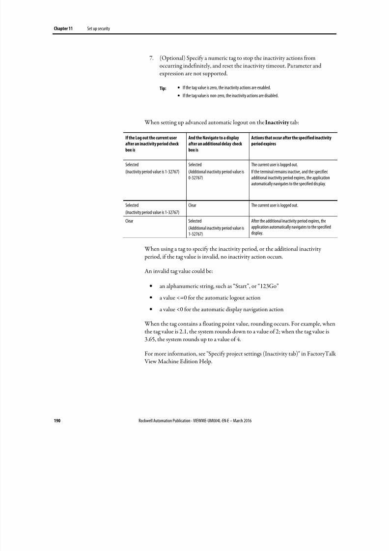
8/17/2019 FactoryTalk® View Machine Edition User's Guide
http://slidepdf.com/reader/full/factorytalk-view-machine-edition-users-guide 190/587
Chapter 11 Set up security
190 Rockwell Automation Publication - VIEWME-UM004L-EN-E – March 2016
7. (Optional) Specify a numeric tag to stop the inactivity actions fromoccurring indefinitely, and reset the inactivity timeout. Parameter andexpression are not supported.
Tip: •
If the tag value is zero, the inactivity actions are enabled.
• If the tag value is non-zero, the inactivity actions are disabled.
When setting up advanced automatic logout on the Inactivity tab:
If the Log out the current user
after an inactivity period check
box is
And the Navigate to a display
after an additional delay check
box is
Actions that occur after the specified inactivity
period expires
Selected
(Inactivity period value is 1-32767)
Selected
(Additional inactivity period value is0-32767)
The current user is logged out.
If the terminal remains inactive, and the specifiedadditional inactivity period expires, the applicationautomatically navigates to the specified dis play.
Selected
(Inactivity period value is 1-32767)
Clear The current user is logged out.
Clear Selected
(Additional inactivity period value is1-32767)
After the additional inactivity period expires, theapplication automatically navigates to the specifieddisplay.
When using a tag to specify the inactivity period, or the additional inactivity
period, if the tag value is invalid, no inactivity action occurs.
An invalid tag value could be:
• an alphanumeric string, such as “Start”, or “123Go”
• a value <=0 for the automatic logout action
• a value <0 for the automatic display navigation action
When the tag contains a floating point value, rounding occurs. For example, whenthe tag value is 2.1, the system rounds down to a value of 2; when the tag value is
3.65, the system rounds up to a value of 4.
For more information, see "Specify project settings (Inactivity tab)" in FactoryTalk View Machine Edition Help.
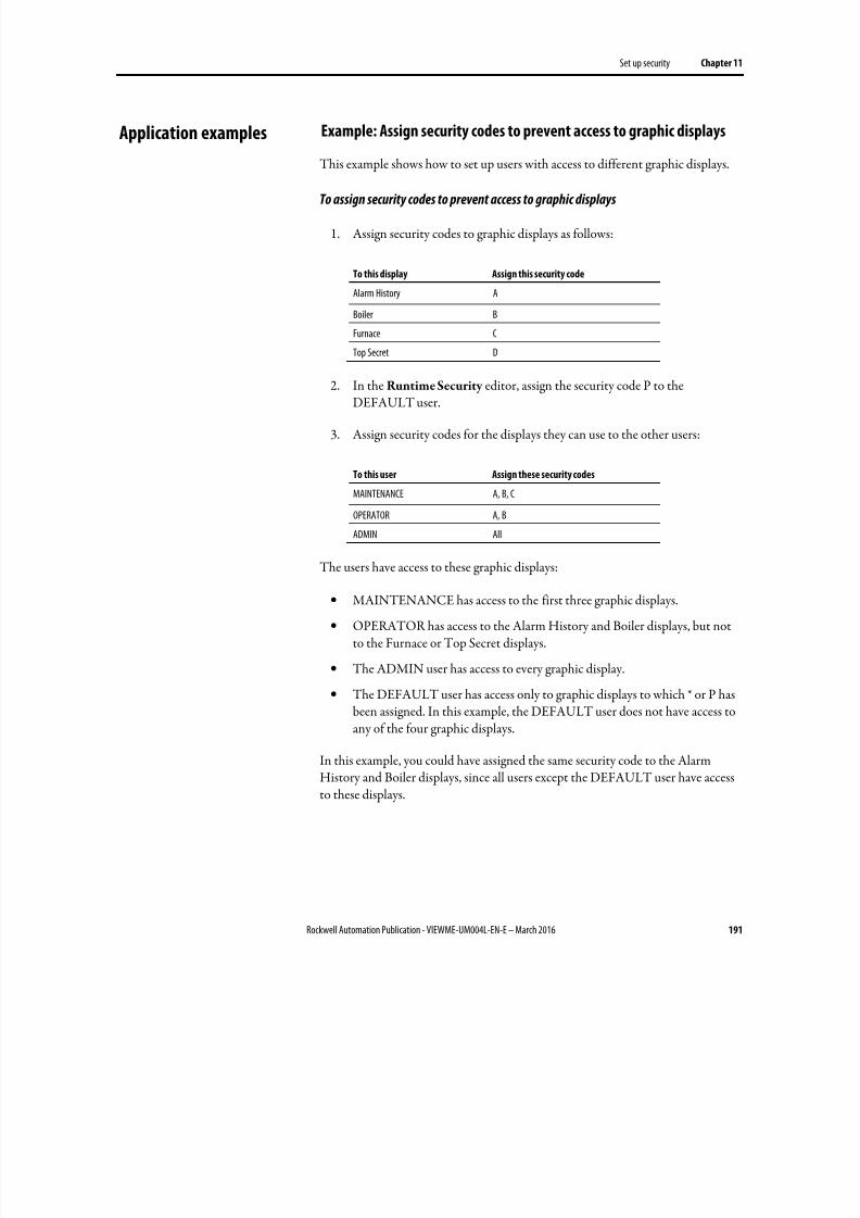
8/17/2019 FactoryTalk® View Machine Edition User's Guide
http://slidepdf.com/reader/full/factorytalk-view-machine-edition-users-guide 191/587
Set up security Chapter 11
Rockwell Automation Publication - VIEWME-UM004L-EN-E – March 2016 191
Example: Assign security codes to prevent access to graphic displays
This example shows how to set up users with access to different graphic displays.
To assign security codes to prevent access to graphic displays
1.
Assign security codes to graphic displays as follows:
To this display Assign this security code
Alarm History A
Boiler B
Furnace C
Top Secret D
2.
In the Runtime Security editor, assign the security code P to theDEFAULT user.
3. Assign security codes for the displays they can use to the other users:
To this user Assign these security codes
MAINTENANCE A, B, C
OPERATOR A, B
ADMIN All
The users have access to these graphic displays:
• MAINTENANCE has access to the first three graphic displays.
• OPERATOR has access to the Alarm History and Boiler displays, but notto the Furnace or Top Secret displays.
• The ADMIN user has access to every graphic display.
• The DEFAULT user has access only to graphic displays to which * or P hasbeen assigned. In this example, the DEFAULT user does not have access toany of the four graphic displays.
In this example, you could have assigned the same security code to the AlarmHistory and Boiler displays, since all users except the DEFAULT user have accessto these displays.
Application examples
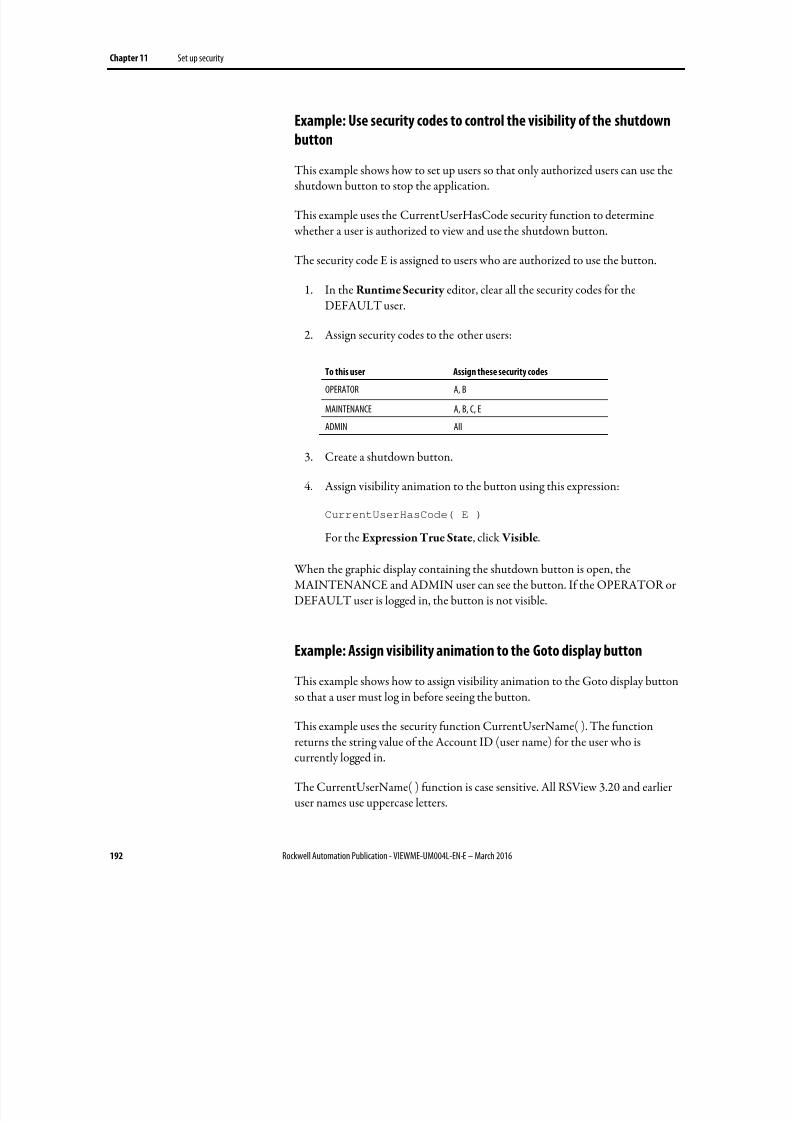
8/17/2019 FactoryTalk® View Machine Edition User's Guide
http://slidepdf.com/reader/full/factorytalk-view-machine-edition-users-guide 192/587
Chapter 11 Set up security
192 Rockwell Automation Publication - VIEWME-UM004L-EN-E – March 2016
Example: Use security codes to control the visibility of the shutdown
button
This example shows how to set up users so that only authorized users can use theshutdown button to stop the application.
This example uses the CurrentUserHasCode security function to determine whether a user is authorized to view and use the shutdown button.
The security code E is assigned to users who are authorized to use the button.
1. In the Runtime Security editor, clear all the security codes for theDEFAULT user.
2. Assign security codes to the other users:
To this user Assign these security codes
OPERATOR A, B
MAINTENANCE A, B, C, E
ADMIN All
3. Create a shutdown button.
4. Assign visibility animation to the button using this expression:
CurrentUserHasCode( E )
For the Expression True State, click Visible.
When the graphic display containing the shutdown button is open, theMAINTENANCE and ADMIN user can see the button. If the OPERATOR orDEFAULT user is logged in, the button is not visible.
Example: Assign visibility animation to the Goto display button
This example shows how to assign visibility animation to the Goto display button
so that a user must log in before seeing the button.
This example uses the security function CurrentUserName( ). The functionreturns the string value of the Account ID (user name) for the user who iscurrently logged in.
The CurrentUserName( ) function is case sensitive. All RSView 3.20 and earlieruser names use uppercase letters.
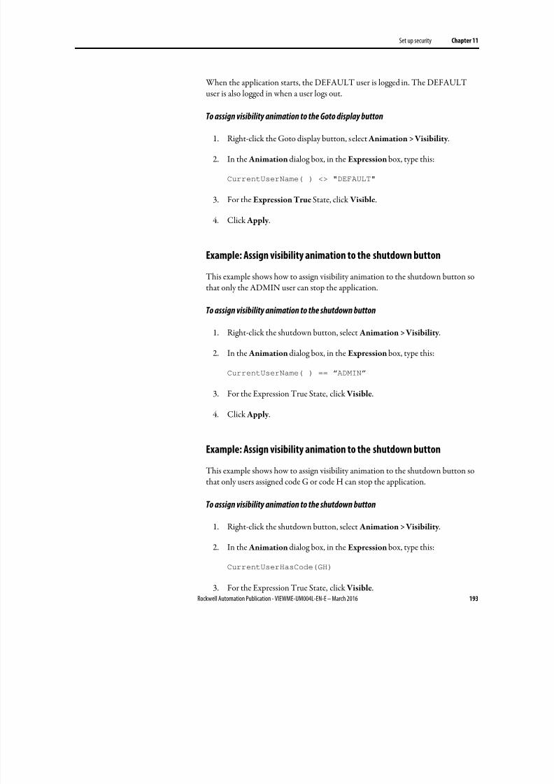
8/17/2019 FactoryTalk® View Machine Edition User's Guide
http://slidepdf.com/reader/full/factorytalk-view-machine-edition-users-guide 193/587
Set up security Chapter 11
Rockwell Automation Publication - VIEWME-UM004L-EN-E – March 2016 193
When the application starts, the DEFAULT user is logged in. The DEFAULTuser is also logged in when a user logs out.
To assign visibility animation to the Goto display button
1. Right-click the Goto display button, select Animation > Visibility .
2. In the Animation dialog box, in the Expression box, type this:
CurrentUserName( ) <> "DEFAULT"
3. For the Expression True State, click Visible.
4. Click Apply .
Example: Assign visibility animation to the shutdown button
This example shows how to assign visibility animation to the shutdown button sothat only the ADMIN user can stop the application.
To assign visibility animation to the shutdown button
1. Right-click the shutdown button, select Animation > Visibility .
2. In the Animation dialog box, in the Expression box, type this:
CurrentUserName( ) == “ADMIN”
3. For the Expression True State, click Visible.
4. Click Apply .
Example: Assign visibility animation to the shutdown button
This example shows how to assign visibility animation to the shutdown button so
that only users assigned code G or code H can stop the application.
To assign visibility animation to the shutdown button
1. Right-click the shutdown button, select Animation > Visibility .
2. In the Animation dialog box, in the Expression box, type this:
CurrentUserHasCode(GH)
3. For the Expression True State, click Visible.
8/17/2019 FactoryTalk® View Machine Edition User's Guide
http://slidepdf.com/reader/full/factorytalk-view-machine-edition-users-guide 194/587
Chapter 11 Set up security
194 Rockwell Automation Publication - VIEWME-UM004L-EN-E – March 2016
4. Click Apply .
Example: Prevent unauthorized users from stopping the application
To prevent unauthorized users from stopping the application
• Do not use a title bar on the application window, because the title barcontains a Close button. To turn off the title bar for the application window, in the Project Settings editor, in the Runtime tab, clear the Title
bar check box.
For more information about using the Project Settings editor, see Work
with applications on page 61.
•
Assign visibility animation to the shutdown button, so that the button isonly visible when a user who is authorized to stop the application is loggedin. For an example, see Example: Use security codes to control the visibilityof the shutdown button on page 192.
Or, set up security for the graphic display, in which the shutdown button is
located, so only users who are authorized to stop the application can open
the display.
Additional step for personal computers
•
Use the DeskLock tool to prevent users from having access to the Windowsdesktop. This will prevent access to operating system functions such asrestarting Windows or shutting down tasks. For more information, see Usethe DeskLock tool on page 244.
Additional step for PanelView Plus CE applications
• Hide the Windows Taskbar to make it inaccessible.
To hide the Windows Taskbar
1.
From Windows Start menu, select Settings > Taskbar .
2. Clear the Always on top check box.
3. Select Auto hide.
4. When you are finished, click OK .
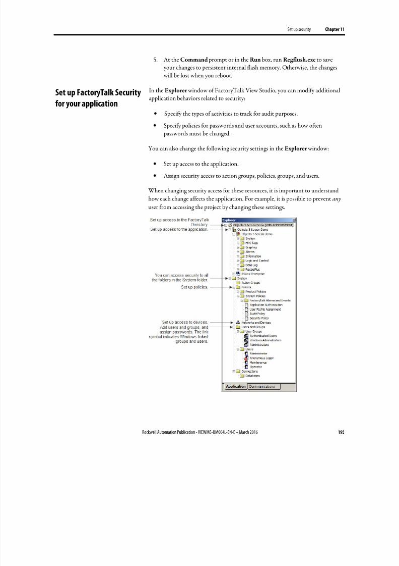
8/17/2019 FactoryTalk® View Machine Edition User's Guide
http://slidepdf.com/reader/full/factorytalk-view-machine-edition-users-guide 195/587
Set up security Chapter 11
Rockwell Automation Publication - VIEWME-UM004L-EN-E – March 2016 195
5. At the Command prompt or in the Run box, run Regflush.exe to save your changes to persistent internal flash memory. Otherwise, the changes will be lost when you reboot.
In the Explorer window of FactoryTalk View Studio, you can modify additionalapplication behaviors related to security:
• Specify the types of activities to track for audit purposes.
• Specify policies for passwords and user accounts, such as how often passwords must be changed.
You can also change the following security settings in the Explorer window:
• Set up access to the application.
•
Assign security access to action groups, policies, groups, and users.
When changing security access for these resources, it is important to understand
how each change affects the application. For example, it is possible to prevent any
user from accessing the project by changing these settings.
Set up FactoryTalk Security
for your application
8/17/2019 FactoryTalk® View Machine Edition User's Guide
http://slidepdf.com/reader/full/factorytalk-view-machine-edition-users-guide 196/587
Chapter 11 Set up security
196 Rockwell Automation Publication - VIEWME-UM004L-EN-E – March 2016
Specify activities to track for audit purposes
You can keep an audit trail of activities such as changing the setup of the
FactoryTalk Directory and whether security access is denied or granted to users.
To specify which activities to track for audit purposes
1. In the System Policies folder, double-click Audit Policy .
2. Set up audit policies. For details, see Help.
Specify policies for passwords, accounts, and FactoryTalk sign-on
You can use the FactoryTalk Directory Security Policy to specify how to manage passwords and user accounts, including how long passwords must be, how oftenthey must be changed (if ever), and whether to keep a record of deleted useraccounts.
Tip: Remember that any changes that you make to system security policies will be included aspart of the runtime application. It is therefore very strongly recommended that you do notalter the default settings in the Security Policy Properties dialog box unless absolutelynecessary, and unless you are aware of the full implications of the changes. A lways test theruntime application to make sure the results are what you intended.
Single sign-on
You can also use the Security Policy to turn off FactoryTalk single sign-on. If youturn this feature off, users must log into FactoryTalk each time FactoryTalk ViewStudio is restarted.
To specify how to manage passwords, user accounts, and FactoryTalk sign-on
1. In the System Policies folder, double-click Security Policy .
2. Set up options for accounts, passwords, and single sign-on. For details, seeHelp.
Uncommon security permissions
Although users can adjust the following security permissions, it is very uncommon.Care must be taken when changing these security permissions from the defaultsettings.
8/17/2019 FactoryTalk® View Machine Edition User's Guide
http://slidepdf.com/reader/full/factorytalk-view-machine-edition-users-guide 197/587
Set up security Chapter 11
Rockwell Automation Publication - VIEWME-UM004L-EN-E – March 2016 197
Set up security access to the FactoryTalk Directory
By default, applications and the System folder inherit the security permissions
assigned to the FactoryTalk Directory. This means that you only need to assign permissions to user groups or users once. If desired, you can override the permissions that you set up at this level by assigning different permissions toapplications and to the items in the System folder.
You can assign permissions for actions related to FactoryTalk View applicationsand tags here or at the application level. If you assign them here, they are inheritedby all applications.
To set security permissions for the FactoryTalk Directory
1. At the top of the tree in the Explorer window, right-click Local and selectSecurity .
2. Specify which users and groups have access to FactoryTalk Directory, andassign permissions to users and groups for the actions listed in the dialogbox. For details, see Help.
Set up security access to the application
Assign FactoryTalk Security at the application level to specify which users orgroups can open the application and add, edit, and delete components. You canalso specify which users or groups can write to tags and set up, view, and respondto alarms.
To set security permissions for the application
1. Right-click the application name, and then select Security .
2. Specify which users and groups have access to the application, and assign permissions to users and groups for the actions listed in the dialog box. Fordetails, see Help.
Set up security access to System policies, groups, and users
You can assign security access to the System folder and to all the folders in theSystem folder, including policies, groups, and users. You do this by specifying which groups and users have access to the folder, and what actions they can perform.

8/17/2019 FactoryTalk® View Machine Edition User's Guide
http://slidepdf.com/reader/full/factorytalk-view-machine-edition-users-guide 198/587
Chapter 11 Set up security
198 Rockwell Automation Publication - VIEWME-UM004L-EN-E – March 2016
To set up security access to policies, groups, and users
1. Right-click the System folder, or a folder in the System folder, and thenselect Security .
2. Specify which groups and users have access to the folder, and what actionsthey can perform. For details, see Help.
Set up security access to networks and devices
You can assign security access to networks and devices in general, to thedevelopment computer, and to specific devices. Set up security for networks anddevices if you are using RSLinx Classic devices.
To set up security access to networks and devices
1. In the System folder, right-click Networks and Devices, the developmentcomputer workstation, or a specific device, and then select Security .
2. Specify which groups and users have access to the item, and what actionsthey can perform. For details, see Help.
8/17/2019 FactoryTalk® View Machine Edition User's Guide
http://slidepdf.com/reader/full/factorytalk-view-machine-edition-users-guide 199/587
Rockwell Automation Publication - VIEWME-UM004L-EN-E – March 2016 199
Chapter 12
Set up language switching
This chapter describes:
• What language switching is
• Summary of steps for setting up language switching
• Set up Windows to support language switching
•
Add languages to the application• Export application text strings for translation
• Translate application text
• Import translated text files
• Switch application languages at design time
• Set up multiple language support for graphic libraries
The FactoryTalk View language switching feature provides the ability to set upmultiple languages for an application and switch languages dynamically at
runtime. You specify an initial language for the runtime application when youcreate it, and select the languages that will be available at runtime. You can use upto 40 languages per development application, and 20 languages per runtimeapplication.
When the application runs, operators can change the language using aLanguage
Switch button. Set up a different Language Switch button for each language.
With language switching you can:
• Develop an application in one language, export the user-defined text strings
for the application, and then import translated strings for up to 40languages into the same application.
• Export an application’s text strings in multiple languages into a singleMicrosoft Excel spreadsheet.
• Import text strings in multiple languages from a Microsoft Excelspreadsheet into your application in a single operation.
• Use the same application in different countries, allowing operators in eachlocation to view the application in their own language.
About language switching

8/17/2019 FactoryTalk® View Machine Edition User's Guide
http://slidepdf.com/reader/full/factorytalk-view-machine-edition-users-guide 200/587
Chapter 12 Set up language switching
200 Rockwell Automation Publication - VIEWME-UM004L-EN-E – March 2016
• Allow operators in multilingual countries to use the language of theirchoice.
• Import application components developed in different countries into a
single application that supports multiple languages.
The default language
For applications that use multiple languages, you can specify one of the languagesas the default language. Any undefined text strings in the other languages can beshown in the default language.
The default language is also used for RSView Machine Edition 4.00 applications. When you open or import the application into FactoryTalk View 5.00 or later, the
application’s alarm, information, and local messages are associated with thelanguage that you select to be the default language. For example, if you open anRSView Machine Edition 4.00 application that contains local messages, and youselect French for the default language, the local messages will be treated as if theyare French when you export the application’s strings for translation. That is, they will appear in the French language column. You can add other languages for thesemessages, as described in this chapter.
When you create a new application, the language you specify for the application isthe default language. You can change the default language at any time. The defaultlanguage can be any of the languages in the application.
You can show undefined strings in the default language during applicationdevelopment. If you do not select this option, undefined strings are shown as aquestion mark "?" character. If you select this option, but do not include thedefault language with the runtime application, undefined strings are shown as aquestion mark "?" character at runtime.
Alarm trigger labels are shown in the Trigger Label Selector list using the defaultlanguage. If you change the default language, you must re-specify the trigger labelsfor every graphic object that filters alarms. To do this, specify the trigger labelnames in the new default language. For more information about filtering alarms when your application uses multiple languages, see Filter alarm triggers in multiplelanguages on page 122.
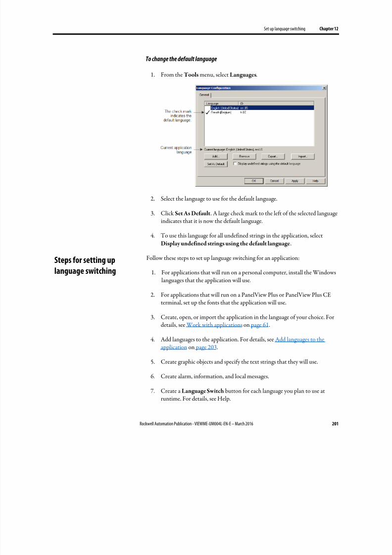
8/17/2019 FactoryTalk® View Machine Edition User's Guide
http://slidepdf.com/reader/full/factorytalk-view-machine-edition-users-guide 201/587
Set up language switching Chapter 12
Rockwell Automation Publication - VIEWME-UM004L-EN-E – March 2016 201
To change the default language
1. From the Tools menu, select Languages.
2. Select the language to use for the default language.
3. Click Set As Default. A large check mark to the left of the selected languageindicates that it is now the default language.
4. To use this language for all undefined strings in the application, selectDisplay undefined strings using the default language.
Follow these steps to set up language switching for an application:
1. For applications that will run on a personal computer, install the Windowslanguages that the application will use.
2. For applications that will run on a PanelView Plus or PanelView Plus CEterminal, set up the fonts that the application will use.
3. Create, open, or import the application in the language of your choice. Fordetails, see Work with applications on page 61.
4.
Add languages to the application. For details, see Add languages to theapplication on page 203.
5. Create graphic objects and specify the text strings that they will use.
6. Create alarm, information, and local messages.
7. Create a Language Switch button for each language you plan to use atruntime. For details, see Help.
Steps for setting uplanguage switching
8/17/2019 FactoryTalk® View Machine Edition User's Guide
http://slidepdf.com/reader/full/factorytalk-view-machine-edition-users-guide 202/587
Chapter 12 Set up language switching
202 Rockwell Automation Publication - VIEWME-UM004L-EN-E – March 2016
8. Export the application text strings for translation. For details, see Exportapplication text strings for translation on page 204.
9. Translate the text strings. For details, see Translate application text in
Unicode files on page 207.
10. Import translated text strings for each of the translation languages. Fordetails, see Import text on page 211.
11. Open the application and switch languages to check the layout of thetranslated text. For details, see Switch application languages at design time on page 212.
12. Create the runtime application, specifying the startup language and thelanguages that the operator can switch to. For details, see Create runtime
applications on page 223.
Install Windows languages
We recommend that you install all the languages that your application will use, onboth the development and runtime computers. Installing languages turns on the Windows font support features, which allow applications to show characters fordifferent languages using a single application font.
For details about installing languages, see Windows Help.
PanelView Plus 7, PanelView Plus 6, PanelView Plus, PanelView Plus Compact,and PanelView Plus CE terminals are shipped with languages already installed.
Set up Windows fonts
For applications that will run on a PanelView Plus 7, PanelView Plus 6, PanelViewPlus, PanelView Plus Compact, or PanelView Plus CE terminal, install the fontsthat the application will use. For applications that will run on a personalcomputer, the fonts you want are generally installed when you install the languages
for the application. Be aware that using MS Arial Unicode as the default font provides better performance for language switching.
For details about choosing fonts that work well with language switching, seeChoose fonts for language switching on page 345.
Make sure that the development and runtime computers are set up to use the fonts you want for the title bar and inactive title bar. Specify the font in the WindowsControl Panel, in the Display Properties dialog box.
Set up Windows for
language switching
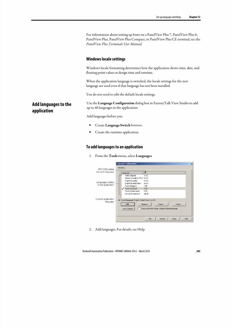
8/17/2019 FactoryTalk® View Machine Edition User's Guide
http://slidepdf.com/reader/full/factorytalk-view-machine-edition-users-guide 203/587
Set up language switching Chapter 12
Rockwell Automation Publication - VIEWME-UM004L-EN-E – March 2016 203
For information about setting up fonts on a PanelView Plus 7, PanelView Plus 6,PanelView Plus, PanelView Plus Compact, or PanelView Plus CE terminal, see the PanelView Plus Terminals User Manual .
Windows locale settings
Windows locale formatting determines how the application shows time, date, andfloating point values at design time and runtime.
When the application language is switched, the locale settings for the newlanguage are used even if that language has not been installed.
You do not need to edit the default locale settings.
Use the Language Configuration dialog box in FactoryTalk View Studio to addup to 40 languages to the application.
Add languages before you:
• Create Language Switch buttons.
• Create the runtime application.
To add languages to an application
1. From the Tools menu, select Languages.
2. Add languages. For details, see Help.
Add languages to the
application
8/17/2019 FactoryTalk® View Machine Edition User's Guide
http://slidepdf.com/reader/full/factorytalk-view-machine-edition-users-guide 204/587
Chapter 12 Set up language switching
204 Rockwell Automation Publication - VIEWME-UM004L-EN-E – March 2016
Remove languages
You can also use the Language Configuration dialog box to remove languages.
When you remove a language, all the strings for the language are deleted the nexttime you save the application. Save a component deletes strings for the removedlanguage from the component.
There are two options for exporting text strings:
• One language at a time, saving the text in a tab-delimited text file inUnicode format. The file can be translated and then imported back into theapplication.
• All languages at once, exporting into a single Microsoft Excel spreadsheet.The strings in the spreadsheet can be translated and then imported back
into the application.
These text strings allow language switching and are exported for translation:
• Display titles for On Top displays (defined in the Display Settings dialogbox)
• Text graphic objects
• Captions that you define for graphic objects, including objects in globalobject displays
• Alarm, local, and information messages
•
Alarm trigger labels
• Embedded time, date, and numeric variables
Undefined strings are exported as undefined strings, regardless of whether youselect the option in the Language Configuration dialog box to show undefinedstrings using the default language. That option is used only for showing stringsduring application development and at runtime. It does not substitute the defaultlanguage’s strings for undefined strings in the exported file or spreadsheet.
Export text in Unicode format
When you export text in Unicode format, these text strings are also exported:
• Text descriptions and error messages for the Change Password window.These strings are exported if you use a password button in your application.
You can translate these strings, but you cannot change their language dynamicallyat runtime the way you can for graphic object strings.
Export application text
strings for translation
8/17/2019 FactoryTalk® View Machine Edition User's Guide
http://slidepdf.com/reader/full/factorytalk-view-machine-edition-users-guide 205/587
Set up language switching Chapter 12
Rockwell Automation Publication - VIEWME-UM004L-EN-E – March 2016 205
For the Change Password window, the runtime application will use the stringsthat are in the application when the runtime application is created. For example, ifthe current application language is French, and you have imported French textstrings for the Change Password window, then the French strings will be compiledin the runtime application. If the operator opens the window, the strings will beshown in French. If the operator changes to another language, the strings will stillbe shown in French.
Unicode file name format
The format for the exported Unicode text file name is< ApplicationName>< HMIServerName>< RFC1766 >.txt, where:
• < ApplicationName> is the name of the application.
•
< HMIServerName> is the name of the HMI server containing the textstrings you exported. This is always the same name as the application name.
• < RFC1766 > is the RFC1766 name associated with the language selected
for the export operation.
For details about the schema of exported Unicode text files, see File schema on page 209.
For a list of Windows languages and the corresponding RFC1766 names, seeMapping languages to RFC1766 names on page 557.
Export text to a Microsoft Excel spreadsheet
FactoryTalk View supports Microsoft Excel versions 2000, 2002, 2003, 2007,2010, and 2013. The exported file is in Microsoft Excel 5.0/95 Workbook format, with the extension .xls.
The maximum number of characters viewable in an Excel cell depends on the version of Excel and the font size. If the maximum is exceeded, the cell will beblank.
Optimizing duplicate strings
When you export text to an Excel spreadsheet, you have the option of optimizingduplicate strings. FactoryTalk View analyzes the text and indicates repeatedinstances of the same string using a reference number. This way the translator onlyneeds to translate the text once. When you import the translated strings from thespreadsheet into the application, FactoryTalk View copies the translated stringinto all the graphic objects that used the string originally.
8/17/2019 FactoryTalk® View Machine Edition User's Guide
http://slidepdf.com/reader/full/factorytalk-view-machine-edition-users-guide 206/587
Chapter 12 Set up language switching
206 Rockwell Automation Publication - VIEWME-UM004L-EN-E – March 2016
Excel spreadsheet file name format
The format for the exported spreadsheet file name is
< ApplicationName>_< ExportVersion>.xls, where:
• < ApplicationName> is the name of the application.
• < ExportVersion> is an incremental number assigned to each successful
export operation.
For details about the schema of exported spreadsheet files, see Translateapplication text in Excel spreadsheet files on page 207.
For a list of Windows languages and the corresponding RFC1766 names, seeMapping languages to RFC1766 names on page 557.
Exported language string file locations
Exported language files are saved in the default folder \Users\Public\Public
Documents\RSView Enterprise\Strings.
You can also specify another location.
To export application text
1.
From the Tools menu, select Languages.
2. In the Language Configuration dialog box, select the application languagefor which to export text strings.
If you are going to export strings for all languages defined for the
application, it does not matter which language is selected in the Language
Configuration dialog box.
3. Click Export.
4.
Follow the instructions in the String Import Export Wizard.
For details about options in the String Import Export wizard, click Help.
If you export to a Unicode text file multiple times to the same location, previouslyexported versions are overwritten.

8/17/2019 FactoryTalk® View Machine Edition User's Guide
http://slidepdf.com/reader/full/factorytalk-view-machine-edition-users-guide 207/587
Set up language switching Chapter 12
Rockwell Automation Publication - VIEWME-UM004L-EN-E – March 2016 207
Problems exporting
You do not have to check every text file created during an export to verify that text
strings were exported correctly. If errors occur, or if you cancel the export while itis in progress, a message appears in the Diagnostics List and in the FactoryTalkDiagnostics log file.
In addition, errors are shown when they occur in a log file called ExportErrors.txt
in \Users\Public\Public Documents\RSView Enterprise\Strings
Existing error log files are overwritten for each subsequent export operation thatgenerates errors.
This section contains information about the format and schema of the exportedMicrosoft Excel spreadsheet file.
The spreadsheet contains a header row followed by a row for each text string inthe application. There is a column for each language defined in the application.The default language is first, followed by the remaining languages in alphabeticalorder by RFC1766 name. All cells use the text format.
Do not delete the header row in the spreadsheet. FactoryTalk View requires thisinformation when you import the translated text into your application. Similarly,do not change the cell formats.
If you select the option to optimize duplicate strings, there is a reference column
to the left of each language column. Do not change the information in thereference columns.
This section contains information about the format and schema of the exportedUnicode text file. It also contains information about using Microsoft Excel or Windows Notepad to edit the file.
Because FactoryTalk View requires that parts of the text file remain the way they were exported, give the information in this section to the translator, to ensure thatthe file can be imported after it has been modified.
File name and format
You will likely want to rename the file before translating it, to avoid confusing it with the original file. You can use any file name ending with the file extension .txt.
To import text into a FactoryTalk View application, you must save the file astab-delimited text, in Unicode text format.
Translate application text
in Excel spreadsheet files
Translate application text
in Unicode files

8/17/2019 FactoryTalk® View Machine Edition User's Guide
http://slidepdf.com/reader/full/factorytalk-view-machine-edition-users-guide 208/587
Chapter 12 Set up language switching
208 Rockwell Automation Publication - VIEWME-UM004L-EN-E – March 2016
Open the text file in Microsoft Excel
When you open the text file in Microsoft Excel, the Text Import Wizard appears.
To specify the file format (Step 1 of the wizard)
1. Click Delimited.
2. In the Start import at row box, type or select 1.
3. In the File origin list, click Windows (ANSI).
4. Click Next.
To specify the field delimiter (Step 2 of the wizard)
1. Select the Tab check box. If any other check boxes are selected, clear them.
2. Make sure the Treat consecutive delimiters as one check box is cleared.
3. Click Next.
To specify the column data format (Step 3 of the wizard)
1. If it is not selected already, under Column data format, click General.
2.
Click Finish.
Save the text file in Microsoft Excel
To save the file
1. From the File menu, select Save.
2. Excel warns that the file may contain features that are not compatible withUnicode text.
3. When prompted to keep the workbook in Unicode format that leaves outincompatible features, click Yes.
4. Close the file.
5. When prompted to save changes, click Yes.
6. When prompted again to keep the workbook in Unicode format that leavesout incompatible features, click Yes.
8/17/2019 FactoryTalk® View Machine Edition User's Guide
http://slidepdf.com/reader/full/factorytalk-view-machine-edition-users-guide 209/587
Set up language switching Chapter 12
Rockwell Automation Publication - VIEWME-UM004L-EN-E – March 2016 209
Differences in file format for files saved in Excel
If you use Notepad to open a Unicode text file that was saved in Excel, you will
notice some differences from a file edited and saved in Notepad.
You do not have to change the format of the file before you import it intoFactoryTalk View.
The differences are:
• Double quotes surrounding the string definitions are removed for moststrings.
• String definitions containing embedded double quotes or other charactersthat Excel treats as special characters, such as commas, are enclosed within
double quotes.• Any embedded double quotes are converted to a pair of double quotes.
Save the Unicode text file in Notepad
When saving the file, save it using the Unicode encoding option in theSave Asdialog box.
File schema
Comments
The text file uses the # symbol as a comment delimiter if it is the first character ona line.
Header
The first seven lines of the text file contain header information that must not betranslated or modified.
Body
The body of the text file starts on line eight, and includes the following columns:
Column Component type Component name String reference "String definition"
Example Graphic Display Pump station 1 "Stop motor"
The file is sorted alphabetically by component name, and then numerically bystring reference number.
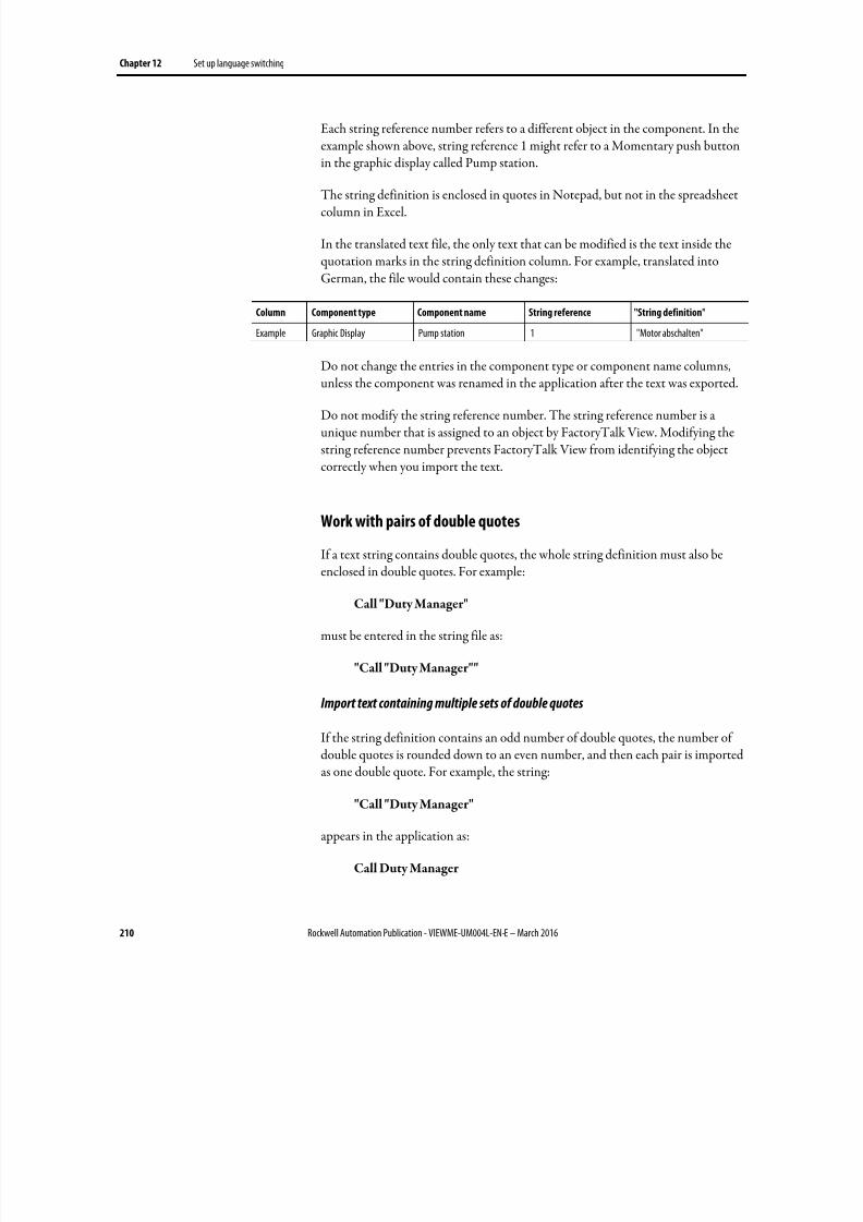
8/17/2019 FactoryTalk® View Machine Edition User's Guide
http://slidepdf.com/reader/full/factorytalk-view-machine-edition-users-guide 210/587
Chapter 12 Set up language switching
210 Rockwell Automation Publication - VIEWME-UM004L-EN-E – March 2016
Each string reference number refers to a different object in the component. In theexample shown above, string reference 1 might refer to a Momentary push buttonin the graphic display called Pump station.
The string definition is enclosed in quotes in Notepad, but not in the spreadsheetcolumn in Excel.
In the translated text file, the only text that can be modified is the text inside thequotation marks in the string definition column. For example, translated intoGerman, the file would contain these changes:
Column Component type Component name String reference "String definition"
Example Graphic Display Pump station 1 "Motor abschalten"
Do not change the entries in the component type or component name columns,
unless the component was renamed in the application after the text was exported.
Do not modify the string reference number. The string reference number is aunique number that is assigned to an object by FactoryTalk View. Modifying thestring reference number prevents FactoryTalk View from identifying the objectcorrectly when you import the text.
Work with pairs of double quotes
If a text string contains double quotes, the whole string definition must also be
enclosed in double quotes. For example:
Call "Duty Manager"
must be entered in the string file as:
"Call "Duty Manager""
Import text containing multiple sets of double quotes
If the string definition contains an odd number of double quotes, the number of
double quotes is rounded down to an even number, and then each pair is importedas one double quote. For example, the string:
"Call "Duty Manager"
appears in the application as:
Call Duty Manager
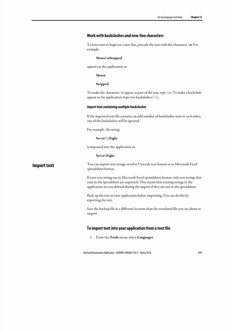
8/17/2019 FactoryTalk® View Machine Edition User's Guide
http://slidepdf.com/reader/full/factorytalk-view-machine-edition-users-guide 211/587
Set up language switching Chapter 12
Rockwell Automation Publication - VIEWME-UM004L-EN-E – March 2016 211
Work with backslashes and new line characters
To force text to begin on a new line, precede the text with the characters \n. For
example:
Motor\nStopped
appears in the application as:
Motor
Stopped
To make the characters \n appear as part of the text, type \\n. To make a backslashappear in the application, type two backslashes ( \\).
Import text containing multiple backslashes
If the imported text file contains an odd number of backslashes next to each other,one of the backslashes will be ignored.
For example, the string:
Seven\\\Eight
is imported into the application as:
Seven\Eight
You can import text strings saved in Unicode text format or in Microsoft Excelspreadsheet format.
If your text strings are in Microsoft Excel spreadsheet format, only text strings thatexist in the spreadsheet are imported. This means that existing strings in theapplication are not deleted during the import if they are not in the spreadsheet.
Back up the text in your application before importing. You can do this byexporting the text.
Save the backup file in a different location than the translated file you are about toimport.
To import text into your application from a text file
1. From the Tools menu, select Languages.
Import text
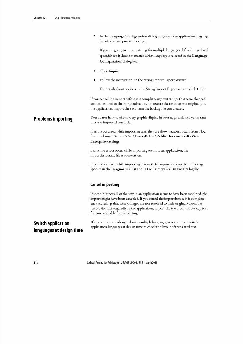
8/17/2019 FactoryTalk® View Machine Edition User's Guide
http://slidepdf.com/reader/full/factorytalk-view-machine-edition-users-guide 212/587
Chapter 12 Set up language switching
212 Rockwell Automation Publication - VIEWME-UM004L-EN-E – March 2016
2. In the Language Configuration dialog box, select the application languagefor which to import text strings.
If you are going to import strings for multiple languages defined in an Excel
spreadsheet, it does not matter which language is selected in the Language
Configuration dialog box.
3. Click Import.
4. Follow the instructions in the String Import Export Wizard.
For details about options in the String Import Export wizard, click Help.
If you cancel the import before it is complete, any text strings that were changedare not restored to their original values. To restore the text that was originally inthe application, import the text from the backup file you created.
You do not have to check every graphic display in your application to verify thattext was imported correctly.
If errors occurred while importing text, they are shown automatically from a logfile called ImportErrors.txt in \Users\Public\Public Documents\RSView
Enterprise\Strings
Each time errors occur while importing text into an application, theImportErrors.txt file is overwritten.
If errors occurred while importing text or if the import was canceled, a messageappears in the Diagnostics List and in the FactoryTalk Diagnostics log file.
Cancel importing
If some, but not all, of the text in an application seems to have been modified, theimport might have been canceled. If you cancel the import before it is complete,any text strings that were changed are not restored to their original values. Torestore the text originally in the application, import the text from the backup text
file you created before importing.
If an application is designed with multiple languages, you may need switchapplication languages at design time to check the layout of translated text.
Problems importing
Switch application
languages at design time
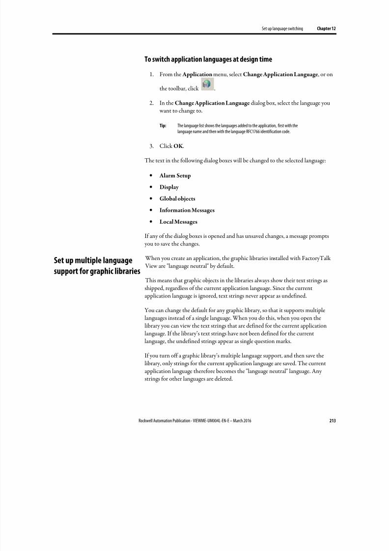
8/17/2019 FactoryTalk® View Machine Edition User's Guide
http://slidepdf.com/reader/full/factorytalk-view-machine-edition-users-guide 213/587
Set up language switching Chapter 12
Rockwell Automation Publication - VIEWME-UM004L-EN-E – March 2016 213
To switch application languages at design time
1. From the Application menu, select Change Application Language, or on
the toolbar, click .
2. In the Change Application Language dialog box, select the language you want to change to.
Tip: The language list shows the languages added to the application, first with thelanguage name and then with the language RFC1766 identification code.
3. Click OK .
The text in the following dialog boxes will be changed to the selected language:
• Alarm Setup
• Display
• Global objects
• Information Messages
• Local Messages
If any of the dialog boxes is opened and has unsaved changes, a message prompts you to save the changes.
When you create an application, the graphic libraries installed with FactoryTalk View are "language neutral" by default.
This means that graphic objects in the libraries always show their text strings asshipped, regardless of the current application language. Since the currentapplication language is ignored, text strings never appear as undefined.
You can change the default for any graphic library, so that it supports multiplelanguages instead of a single language. When you do this, when you open thelibrary you can view the text strings that are defined for the current applicationlanguage. If the library’s text strings have not been defined for the current
language, the undefined strings appear as single question marks.
If you turn off a graphic library’s multiple language support, and then save thelibrary, only strings for the current application language are saved. The currentapplication language therefore becomes the "language neutral" language. Anystrings for other languages are deleted.
Set up multiple language
support for graphic libraries
8/17/2019 FactoryTalk® View Machine Edition User's Guide
http://slidepdf.com/reader/full/factorytalk-view-machine-edition-users-guide 214/587
Chapter 12 Set up language switching
214 Rockwell Automation Publication - VIEWME-UM004L-EN-E – March 2016
To turn on support for multiple languages in a graphic library
1. Right-click an empty area in the graphic library display, and then select
Display Settings.
2. In the General tab, select Support Multiple Languages.
After you turn on support for multiple languages, when you save the graphiclibrary, all strings that support language switching are saved in the currentapplication language. For information about saving libraries in multiple languages,see Use libraries to store displays with multiple languages on page 319.
Use graphic libraries that support multiple languages
To use the graphics libraries in an application, you can add a graphic library intothe Displays folder or copy objects from a graphic library into a graphic display. Ifthe graphic library supports multiple languages:
• When you add the graphic library into the Displays folder, all strings,including strings for languages that are not supported by the application, areincluded with the display.
• If you copy an object from the graphic library into a graphic display, onlystrings for languages supported by the application are copied.
For more information about using graphic libraries, see Use graphic displays on page 303.
8/17/2019 FactoryTalk® View Machine Edition User's Guide
http://slidepdf.com/reader/full/factorytalk-view-machine-edition-users-guide 215/587
Rockwell Automation Publication - VIEWME-UM004L-EN-E – March 2016 215
Chapter 13
Set up display navigation
This chapter describes:
• What display navigation is
• Develop a hierarchy of displays
• Test display navigation
•
Use graphic objects to navigate• Control display changes remotely
This chapter describes methods for navigating between graphic displays. Forinformation about navigating between objects on a graphic display, see Use thekeyboard to navigate to and select objects on page 407.
The term display navigation refers to the way the operator moves between thegraphic displays that make up an application.
Use these methods to set up display navigation for your application:
• Develop a hierarchy of graphic displays, to chart how users will navigate theapplication.
• Determine which users will have access to which parts of the application.
• Create graphic objects that the operator can use to navigate the application.
• Use the Remote Display Number connection to automatically controldisplay changes. The use of this connection is optional. Assign it in theGlobal Connections editor.
• In the Startup editor, specify the graphic display to open when the
application starts.• Set up security so that only authorized users have access to the application
or parts of the application.
For information about setting up security, see Set up security on page 175.
About display navigation
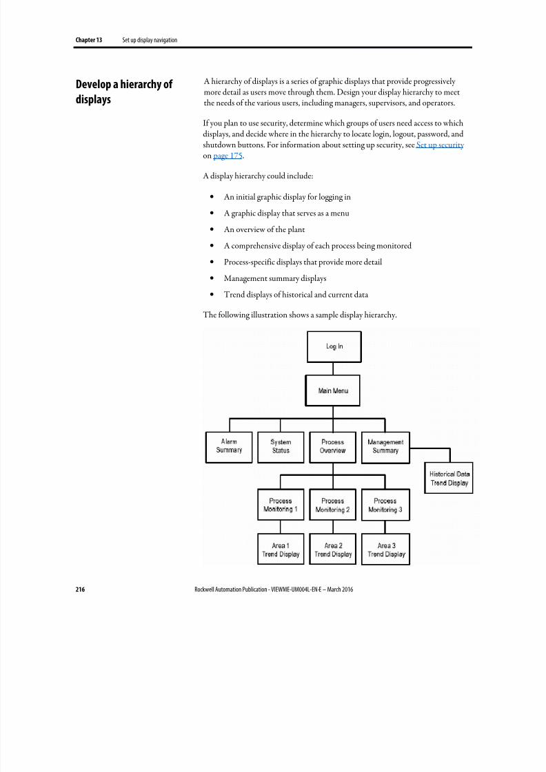
8/17/2019 FactoryTalk® View Machine Edition User's Guide
http://slidepdf.com/reader/full/factorytalk-view-machine-edition-users-guide 216/587
Chapter 13 Set up display navigation
216 Rockwell Automation Publication - VIEWME-UM004L-EN-E – March 2016
A hierarchy of displays is a series of graphic displays that provide progressivelymore detail as users move through them. Design your display hierarchy to meetthe needs of the various users, including managers, supervisors, and operators.
If you plan to use security, determine which groups of users need access to whichdisplays, and decide where in the hierarchy to locate login, logout, password, andshutdown buttons. For information about setting up security, see Set up security on page 175.
A display hierarchy could include:
• An initial graphic display for logging in
• A graphic display that serves as a menu
• An overview of the plant
• A comprehensive display of each process being monitored
• Process-specific displays that provide more detail
• Management summary displays
• Trend displays of historical and current data
The following illustration shows a sample display hierarchy.
Develop a hierarchy of
displays
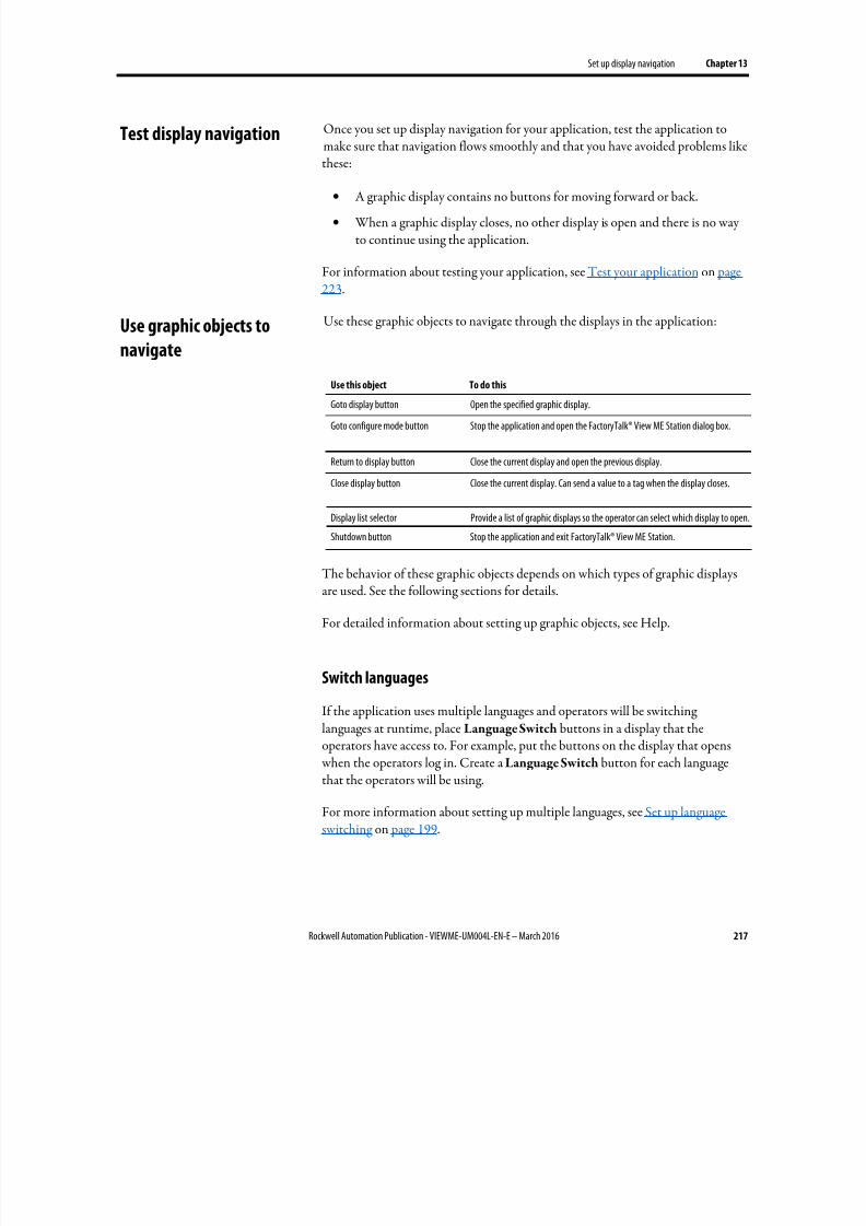
8/17/2019 FactoryTalk® View Machine Edition User's Guide
http://slidepdf.com/reader/full/factorytalk-view-machine-edition-users-guide 217/587
Set up display navigation Chapter 13
Rockwell Automation Publication - VIEWME-UM004L-EN-E – March 2016 217
Once you set up display navigation for your application, test the application tomake sure that navigation flows smoothly and that you have avoided problems likethese:
•
A graphic display contains no buttons for moving forward or back.
• When a graphic display closes, no other display is open and there is no wayto continue using the application.
For information about testing your application, see Test your application on page223.
Use these graphic objects to navigate through the displays in the application:
Use this object To do this
Goto display button Open the specified graphic display.
Goto configure mode button Stop the application and open the FactoryTalk® View ME Station dialog box.
Return to display button Close the current display and open the previous display.
Close display button Close the current display. Can send a value to a tag when the display closes.
Display list selector Provide a list of graphic displays so the operator can select which display to open.
Shutdown button Stop the application and exit FactoryTalk® View ME Station.
The behavior of these graphic objects depends on which types of graphic displaysare used. See the following sections for details.
For detailed information about setting up graphic objects, see Help.
Switch languages
If the application uses multiple languages and operators will be switchinglanguages at runtime, place Language Switch buttons in a display that theoperators have access to. For example, put the buttons on the display that opens
when the operators log in. Create a Language Switch button for each languagethat the operators will be using.
For more information about setting up multiple languages, see Set up languageswitching on page 199.
Test display navigation
Use graphic objects to
navigate
8/17/2019 FactoryTalk® View Machine Edition User's Guide
http://slidepdf.com/reader/full/factorytalk-view-machine-edition-users-guide 218/587
Chapter 13 Set up display navigation
218 Rockwell Automation Publication - VIEWME-UM004L-EN-E – March 2016
Display type
The display type you use gives you additional control over how the operator
navigates between displays. For example, use the On Top type to keep a graphicdisplay on top at all times, even when another display has focus. Or use theReplace type if you want a display to replace all other open displays when it opens.
For more information about display types, see About display types on page 313.
Goto display buttons
When you set up a Goto display button, specify the graphic display to open whenthe operator presses the button at runtime.
The specified display does not open if the operator does not have security accessfor the display.
You can also assign a parameter file or parameter list that assigns tags to tag placeholders on the display when the display opens. For more information about parameter files and lists, see Use parameters and global objects on page 461.
For information about setting up Goto display buttons, see Help.
How display types affect the button’s behavior
The Goto display button’s behavior at runtime also depends on which types ofgraphic displays are already open and which type of display it is opening:
• If the graphic display assigned to the button is a Replace display, it closes anyopen On Top or Replace displays. It does not close any On Top displaysthat use the Cannot Be Replaced option.
• If the display assigned to the button is already open, but does not have focus, pressing the button gives the display focus.
The operator cannot use the Goto display button to open Replace displays ifdisplay change is currently controlled remotely (using global connections). But theoperator can still open On Top displays.
Goto configure mode buttons
When the operator presses a goto configure mode button at runtime, the currentapplication stops running and the FactoryTalk View ME Station dialog boxopens.
8/17/2019 FactoryTalk® View Machine Edition User's Guide
http://slidepdf.com/reader/full/factorytalk-view-machine-edition-users-guide 219/587
Set up display navigation Chapter 13
Rockwell Automation Publication - VIEWME-UM004L-EN-E – March 2016 219
While in configure mode, the operator can use FactoryTalk View ME Station tochange applications, application settings, and terminal settings. The operator canalso delete log files. For more information about the FactoryTalk View ME
Station dialog box, see Run applications on a personal computer on page 229.
Return to display buttons
When the operator presses a return to display button at runtime, the graphicdisplay that the button is on closes and the display that was previously openreopens.
The current display does not close if:
• The display change is currently controlled remotely (using global
connections).
• There were no previously opened Replace displays.
• The operator does not have security access for the previous display. This canonly occur if a new user logs in using a login button in the current display.
The return to display button only goes back to the most recent display. It does notgo back through a series of displays.
For information about setting up return to display buttons, see Help.
How display types affect the button’s behavior
Both the current display and the previous display must be Replace displays. Whenthe operator presses the return to display button:
• If the graphic display that is closing is a Replace display, the display closesand the previously opened Replace display opens. Any On Top displays that were previously open with the Replace display are not reopened.
• If the graphic display that is closing is an On Top display, the display closesbut no display is reopened.
We therefore recommend that you use return to display buttons in Replacedisplays only.
Example: Navigating through displays
This example uses the display hierarchy illustrated in Develop a hierarchy ofdisplays on page 216, and shows what happens as the operator navigates throughthe hierarchy. The graphic displays are all Replace displays.
8/17/2019 FactoryTalk® View Machine Edition User's Guide
http://slidepdf.com/reader/full/factorytalk-view-machine-edition-users-guide 220/587
Chapter 13 Set up display navigation
220 Rockwell Automation Publication - VIEWME-UM004L-EN-E – March 2016
1. In the Main Menu display, the operator uses a display list selector to openthe Process Overview display.
2. In the Process Overview display, the operator presses a Goto display button
to open the Process Monitoring 1 display.
3. After viewing the state of the process, the operator presses a return todisplay button to close the current display and reopen the Process Overviewdisplay.
4. In the Process Overview display, the operator presses a return to displaybutton. Which display opens? The Process Monitoring 1 display (becausethis was the previously opened display).
To return to the Main Menu display from the Process Overview display, the
operator would have to press a Goto display button that is set up to openthe Main Menu display.
Close display buttons
When the operator presses a close display button at runtime, the graphic displaythat the button is on closes. You can set up the button to write out a value whenthe display closes.
If the graphic display that is closing is a Replace display, and the display change is
controlled remotely, the display does not close. If the display does not close, theclose value, if any, is not written out.
If the display change is controlled by the operator and the graphic display that isclosing is a Replace display, if there are no On Top displays open, an empty window is shown. The operator will not be able to use the application again(unless a remote display change occurs or an alarm, activity, or informationmessage display opens).
We therefore recommend that you use close display buttons in On Top displaysonly.
For information about setting up close display buttons, see Help.
Display list selectors
Use the display list selector to show a list of graphic displays that the operator canchoose from. The operator can scroll through the list and select the graphic displayto open.
8/17/2019 FactoryTalk® View Machine Edition User's Guide
http://slidepdf.com/reader/full/factorytalk-view-machine-edition-users-guide 221/587
Set up display navigation Chapter 13
Rockwell Automation Publication - VIEWME-UM004L-EN-E – March 2016 221
The specified display does not open if the operator does not have security accessfor the display.
You can also assign a parameter file or parameter list that assigns tags to tag
placeholders on the display when the display opens. For more information about parameter files and lists, see Use parameters and global objects on page 461.
For information about setting up display list selectors, see Help.
How display types affect the selector’s behavior
The display list selector’s behavior at runtime also depends on which types ofgraphic displays are already open and which type of display it is opening:
• If the selected graphic display is a Replace display, it closes any open On
Top and Replace displays. It does not close On Top displays that use theCannot Be Replaced option.
• If the selected display is an On Top display, it opens on top of the currentdisplay. The current display does not close.
The operator cannot use the display list selector to open Replace displays if displaychange is currently controlled remotely. But the operator can still open On Topdisplays (with or without the Cannot Be Replaced option).
Select the display to open
The operator can scroll through the list and select displays using the key buttongraphic objects, or, if the list has the input focus, by using the arrow keys and Enterkey on a keypad or external keyboard.
You can link key buttons to a specific display list selector, or set up the buttons to work with whichever object is selected in the graphic display.
For information about input focus, see What input focus looks like on page 407.For information about linking buttons to the display list selector, see Link buttonsto objects on page 408.
Shutdown buttons
When the operator presses the shutdown button at runtime, the application stopsand FactoryTalk View ME Station closes.
To prevent an unauthorized user from stopping the application, assign visibilityanimation to the shutdown button. For details, see Application examples on page191. Or, place the button in a display that only authorized users have access to.

8/17/2019 FactoryTalk® View Machine Edition User's Guide
http://slidepdf.com/reader/full/factorytalk-view-machine-edition-users-guide 222/587
Chapter 13 Set up display navigation
222 Rockwell Automation Publication - VIEWME-UM004L-EN-E – March 2016
For information about setting up shutdown buttons, see Help.
To control display changes remotely, you can set up the data source to opengraphic displays using global connections.
For example, the Remote Display Number connection is a global connectionthat you can use to control display changes from the data source.
For more information, see About global connections on page 111.
Control display changes
remotely
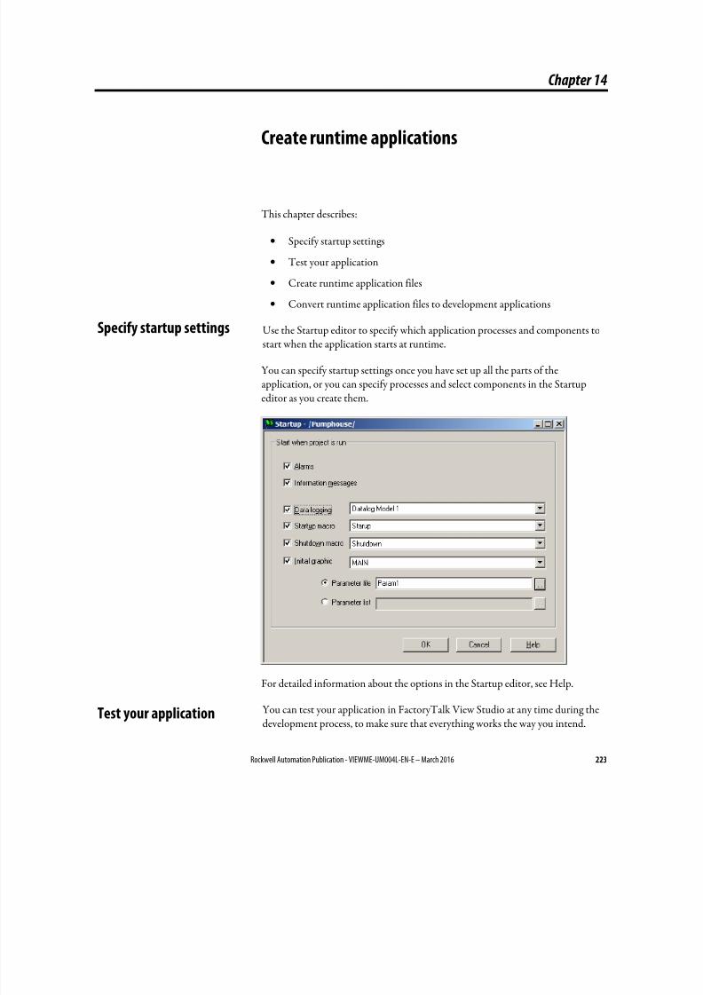
8/17/2019 FactoryTalk® View Machine Edition User's Guide
http://slidepdf.com/reader/full/factorytalk-view-machine-edition-users-guide 223/587
Rockwell Automation Publication - VIEWME-UM004L-EN-E – March 2016 223
Chapter 14
Create runtime applications
This chapter describes:
• Specify startup settings
• Test your application
• Create runtime application files
•
Convert runtime application files to development applications
Use the Startup editor to specify which application processes and components tostart when the application starts at runtime.
You can specify startup settings once you have set up all the parts of theapplication, or you can specify processes and select components in the Startupeditor as you create them.
For detailed information about the options in the Startup editor, see Help.
You can test your application in FactoryTalk View Studio at any time during thedevelopment process, to make sure that everything works the way you intend.
Specify startup settings
Test your application
8/17/2019 FactoryTalk® View Machine Edition User's Guide
http://slidepdf.com/reader/full/factorytalk-view-machine-edition-users-guide 224/587
Chapter 14 Create runtime applications
224 Rockwell Automation Publication - VIEWME-UM004L-EN-E – March 2016
If the development computer is connected to the data source, you can test allfunctions of the application, including security settings, language switching,communications, and alarm monitoring.
A FactoryTalk View ME Station emulator opens on the development computerand runs the application. This runtime version of the application is a temporary version for testing use only. You cannot run it on another computer.
There is a two-hour time limit for test running the application in FactoryTalk View Studio.
The procedure in this section shows you how to test your entire application. Forinformation about testing a single graphic display, see Test your displays as you work on page 311.
To test your application in FactoryTalk View Studio
1. On the Application menu, click Test Application, or click the Test
Application tool .
2. If your application uses multiple languages, specify the languages to includeand the initial runtime language, and then press Finish. For details, seeHelp.
3. Test your application.
4. To stop your application, press a shutdown button, or type the character ‘x.’
Make sure you provide the operator with a method for shutting down the
application at runtime. For more information about methods for shutting
down applications, see Shut down applications on page 234.
Once you have tested your application to make sure everything works the way youintend, create the runtime application file and transfer the file to the runtimecomputer.
Before you can run your application, you must create a runtime version. When you create the runtime version, FactoryTalk View Studio compiles all of thenecessary application information into a single file with the extension .mer.
Create .mer files for previous versions
You can specify the version of FactoryTalk View ME Station for which to createthe .mer file. For example, if the application will run on a terminal that usesFactoryTalk View ME Station 5.10, you can specify that version for the .mer file.
Create runtime applicationfiles

8/17/2019 FactoryTalk® View Machine Edition User's Guide
http://slidepdf.com/reader/full/factorytalk-view-machine-edition-users-guide 225/587
Rockwell Automation Publication - VIEWME-UM004L-EN-E – March 2016 225
Tip: Version 6.0 or earlier .mer files created on a 64-bit operating system cannot be convertedto design-time projects (.med).
If the application contains features that are not supported by the version youselect, FactoryTalk View shows a validation report that lists the unsupportedfeatures. The runtime application file is not created. You must remove or turn off
the unsupported features before you can create the runtime application file.
For information about the features supported in different versions of FactoryTalk View, and how to remove or replace them, see Features supported in different versions of FactoryTalk View on page 561.
Note: PanelView Plus 7 or PanelView Plus 6 terminals cannot process a Gradient Fill that uses aDiagonal Up or Diagonal Down direction, nor can the PanelView Plus 7 or PanelView Plus 6terminal apply a Gradient Fill to a rotated object. While running an MER on a PanelViewPlus 7 or PanelView Plus 6 terminal, the gradient attributes will be anim ated using thegradient fill starting color as the object’s solid color background.
When running the MER on a computer, the system can process all gradient fills and thiswarning does not apply.
Convert .mer files to development applications
For FactoryTalk View version 5.00 and later .mer files, you can convert theruntime .mer file back to a development application (.med file). This option isuseful if:
• You lose or don’t have access to the original .med file and you need to makea change to the application.
•
You make changes to the .mer file at runtime, such as adding passwords,updating RSLinx Enterprise device shortcuts, or saving recipes, and youneed to make a change to the application but don’t want to lose thisruntime information.
Starting with FactoryTalk View 8.0, all security information modified at
runtime is saved in the .mer files. These changes will be restored after
converting FactoryTalk View 8.0 .mer files to .med files.
• You need to extract information that was generated at runtime, such asupdated RecipePlus files.
Version 6.0 or earlier .mer files created on a 64-bit operating system cannot beconverted to design-time projects (MED files). This is due to an incompatibility ofthe previous FactoryTalk View database engine with 64-bit operating systems.Thus, when you create a version 6.0 or earlier .MER file on a workstation running64-bit operating system, the only option available in FactoryTalk View Studio isNever allow conversion. When creating a version 6.0 or earlier .MER on a workstation running a 64-bit operating system, this is the default option (and onlychoice) for the Conversion to development application setting .
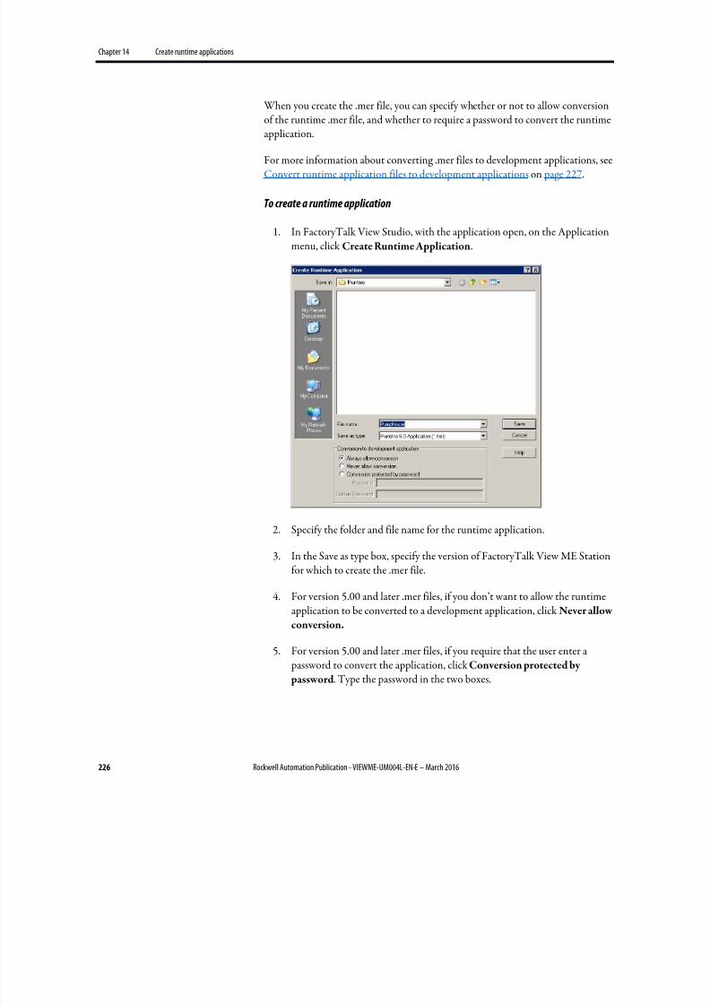
8/17/2019 FactoryTalk® View Machine Edition User's Guide
http://slidepdf.com/reader/full/factorytalk-view-machine-edition-users-guide 226/587
Chapter 14 Create runtime applications
226 Rockwell Automation Publication - VIEWME-UM004L-EN-E – March 2016
When you create the .mer file, you can specify whether or not to allow conversionof the runtime .mer file, and whether to require a password to convert the runtimeapplication.
For more information about converting .mer files to development applications, seeConvert runtime application files to development applications on page 227.
To create a runtime application
1. In FactoryTalk View Studio, with the application open, on the Applicationmenu, click Create Runtime Application.
2. Specify the folder and file name for the runtime application.
3. In the Save as type box, specify the version of FactoryTalk View ME Stationfor which to create the .mer file.
4. For version 5.00 and later .mer files, if you don’t want to allow the runtimeapplication to be converted to a development application, click Never allow
conversion.
5. For version 5.00 and later .mer files, if you require that the user enter a password to convert the application, click Conversion protected by
password. Type the password in the two boxes.
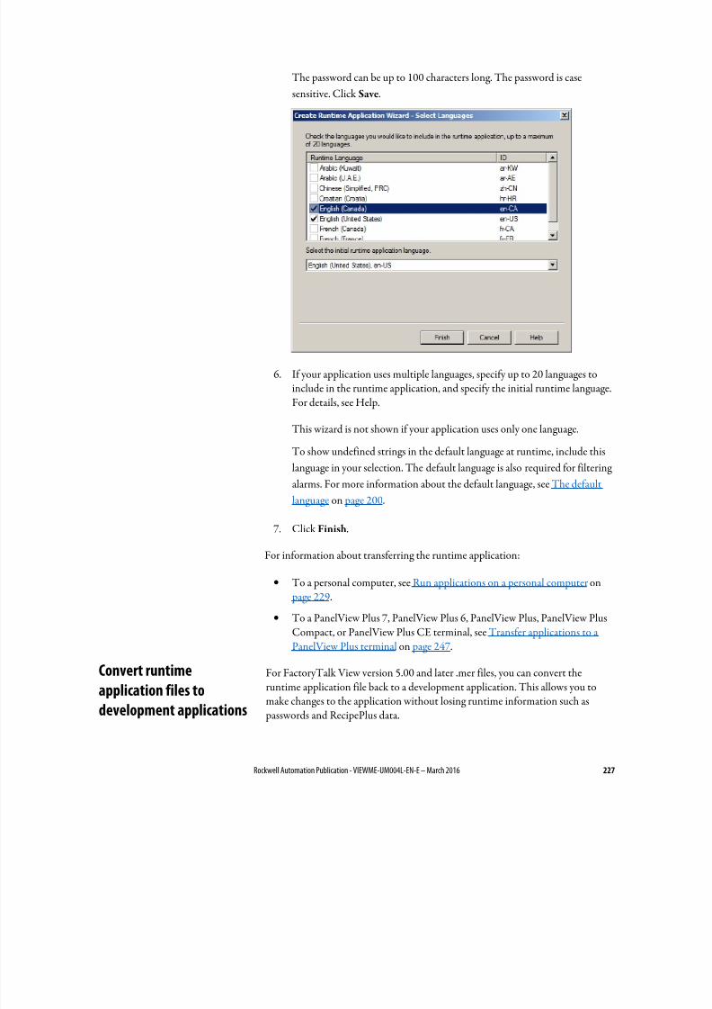
8/17/2019 FactoryTalk® View Machine Edition User's Guide
http://slidepdf.com/reader/full/factorytalk-view-machine-edition-users-guide 227/587
Rockwell Automation Publication - VIEWME-UM004L-EN-E – March 2016 227
The password can be up to 100 characters long. The password is case
sensitive. Click Save.
6. If your application uses multiple languages, specify up to 20 languages toinclude in the runtime application, and specify the initial runtime language.For details, see Help.
This wizard is not shown if your application uses only one language.
To show undefined strings in the default language at runtime, include this
language in your selection. The default language is also required for filteringalarms. For more information about the default language, see The default
language on page 200.
7. Click Finish.
For information about transferring the runtime application:
• To a personal computer, see Run applications on a personal computer on page 229.
• To a PanelView Plus 7, PanelView Plus 6, PanelView Plus, PanelView PlusCompact, or PanelView Plus CE terminal, see Transfer applications to aPanelView Plus terminal on page 247.
For FactoryTalk View version 5.00 and later .mer files, you can convert theruntime application file back to a development application. This allows you tomake changes to the application without losing runtime information such as passwords and RecipePlus data.
Convert runtime
application files to
development applications
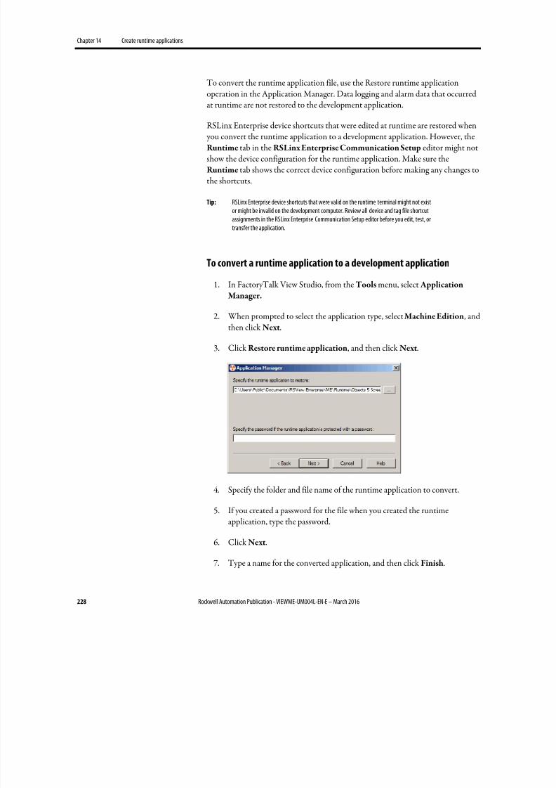
8/17/2019 FactoryTalk® View Machine Edition User's Guide
http://slidepdf.com/reader/full/factorytalk-view-machine-edition-users-guide 228/587
Chapter 14 Create runtime applications
228 Rockwell Automation Publication - VIEWME-UM004L-EN-E – March 2016
To convert the runtime application file, use the Restore runtime applicationoperation in the Application Manager. Data logging and alarm data that occurredat runtime are not restored to the development application.
RSLinx Enterprise device shortcuts that were edited at runtime are restored when you convert the runtime application to a development application. However, theRuntime tab in the RSLinx Enterprise Communication Setup editor might notshow the device configuration for the runtime application. Make sure theRuntime tab shows the correct device configuration before making any changes tothe shortcuts.
Tip: RSLinx Enterprise device shortcuts that were valid on the runtime terminal might not existor might be invalid on the development computer. Review all device and tag file shortcutassignments in the RSLinx Enterprise Communication Setup editor before you edit, test, ortransfer the application.
To convert a runtime application to a development application
1. In FactoryTalk View Studio, from the Tools menu, select Application
Manager.
2. When prompted to select the application type, select Machine Edition, andthen click Next.
3. Click Restore runtime application, and then click Next.
4.
Specify the folder and file name of the runtime application to convert.
5. If you created a password for the file when you created the runtimeapplication, type the password.
6. Click Next.
7. Type a name for the converted application, and then click Finish.
8/17/2019 FactoryTalk® View Machine Edition User's Guide
http://slidepdf.com/reader/full/factorytalk-view-machine-edition-users-guide 229/587
Rockwell Automation Publication - VIEWME-UM004L-EN-E – March 2016 229
Chapter 15
Run applications on a personal computer
This chapter describes:
• Install printers and software on the runtime computer
• Move applications to the runtime computer
• Start FactoryTalk View ME Station
•
Load and run applications• Shut down applications
• Edit device short cuts
• Look up contact information for technical support
• Set up FactoryTalk Diagnostics at runtime
• Set up serial ports for KEPServer Enterprise
• Set up RSLinx Enterprise communication drivers
• Specify the printers to use at runtime
• Specify startup options for FactoryTalk View ME Station
• Delete log files on the runtime computer
• Specify the time, date, and number formats to use at runtime
• Use the DeskLock tool
Follow these steps to:
• Install the necessary hardware and software on the run-time computer.
• Transfer your application to the run-time computer.
• Set up options in FactoryTalk View ME Station.
For information about installing FactoryTalk View ME Station, see FactoryTalk
View Machine Edition Installation Guide.
Steps for running an
application on a personal
computer
8/17/2019 FactoryTalk® View Machine Edition User's Guide
http://slidepdf.com/reader/full/factorytalk-view-machine-edition-users-guide 230/587
Chapter 15 Run applications on a personal computer
230 Rockwell Automation Publication - VIEWME-UM004L-EN-E – March 2016
Install printers and software on the runtime computer
1. If you will be printing displays, alarms, or diagnostics messages, set up printer connections on the runtime computer.
For more information, see Specify the printers to use at runtime on page
238.
2. If you are using RSLinx Enterprise, set up communications as described inSet up communications on page 81.
3. If you are using RSLinx Classic as the OPC server on the runtime computer,install RSLinx Classic on the runtime computer.
4.
If you are using RSLinx Classic on a remote computer, install RSLinx
Classic on the remote computer.
5. If you are using an OPC server other than RSLinx Enterprise or RSLinxClassic, install the OPC server software on the runtime computer or onanother computer on the network.
For installation information, see the documentation supplied by your OPC
server vendor. For information about OPC, see Set up communications on
page 81.
6.
If your application uses third-party ActiveX objects, install and register the
Windows 7, Windows 8, Windows 8.1, Windows Server 2008, and Windows Server 2012 version of the objects on the runtime computer.
For information about ActiveX objects, see Use ActiveX objects on page
355.
7. Install on the runtime computer all languages used by the runtimeapplication.
8. If the runtime computer uses different time, date, or number formats thanthe development computer, specify the time, date, and number formats to
use at runtime.
For more information, see Specify time, date, and number formats on page
244.
9. If desired, use the DeskLock tool to prevent users from switching to anothersoftware application or using the Windows desktop at runtime.
For more information, see Use the DeskLock tool on page 244.

8/17/2019 FactoryTalk® View Machine Edition User's Guide
http://slidepdf.com/reader/full/factorytalk-view-machine-edition-users-guide 231/587
Rockwell Automation Publication - VIEWME-UM004L-EN-E – March 2016 231
Transfer the application
Move the application to the runtime personal computer.
For more information, see Move applications to the runtime computer on page232.
Set up options in FactoryTalk View ME Station
1. On the runtime computer, start FactoryTalk View ME Station.
For more information, see Start FactoryTalk View Machine Edition Station
on the development computer on page 232.
2. Load the application.
For more information, see Load and run applications on page 232.
3. Edit device shortcuts, if necessary.
For more information, see Edit device shortcuts on page 234.
4. Set up FactoryTalk Diagnostics on the runtime computer (if you have notalready done so).
For more information, see Use the Diagnostics Setup tool on page 166.
5.
If you will be using KEPServer Enterprise, specify serial port IDs.
For more information, see Set up serial ports for use with KEPServer
Enterprise on page 236.
6. If you will be using RSLinx Enterprise, set up communication drivers (if youhave not already done so).
For more information, see Set up RSLinx Enterprise communication drivers
on page 237.
7.
Specify the printers to use.
For more information, see Specify the printers to use at runtime on page
238.
8. Specify startup options for FactoryTalk View ME Station.
For more information, see Specify startup options for FactoryTalk View
ME Station on page 239.
8/17/2019 FactoryTalk® View Machine Edition User's Guide
http://slidepdf.com/reader/full/factorytalk-view-machine-edition-users-guide 232/587
Chapter 15 Run applications on a personal computer
232 Rockwell Automation Publication - VIEWME-UM004L-EN-E – March 2016
Once you have completed these steps, you’re ready to run the application. Forinformation about running your application, see Use your application on page255.
The runtime application file has the extension .mer. You can use any standard filetransfer method to copy your runtime application from the developmentcomputer to the runtime computer.
You can:
• Copy the application file from the development computer to removablemedia such as USB thumb drive or USB hard drive, and then from theremovable media to the runtime computer.
• If the development and runtime computers are on the same network, use Windows Explorer or My Computer to move the file.
For information about creating the runtime application file, see Create runtimeapplications on page 223.
To start FactoryTalk View Machine Edition Station on the development
computer, do one of the following:
• From Windows Start menu, select Programs > Rockwell Software >
FactoryTalk View > FactoryTalk View ME Station.
• On the desktop, double-click the shortcut icon FTView ME Station.
•
In the Windows Explorer, right-click MERuntime.exe and select Run as
administrator . Default location for this file is \Program Files\Rockwell
Software\RSView Enterprise\MERuntime.exe
• From Windows Start menu, select Run. In the Open box, type the path tothe MERuntime.exe file.
If you are running an application on the development computer, we recommendthat you exit FactoryTalk View Studio before starting FactoryTalk View MEStation.
For information about specifying startup options for FactoryTalk View MachineEdition Station, see Specify startup options for FactoryTalk View ME Station on page 239.
You can run any runtime application that is on the runtime computer. Runtimeapplications have the extension .mer.
Move applications to the
runtime computer
Start FactoryTalk View
Machine Edition Station on
the development computer
Load and run applications
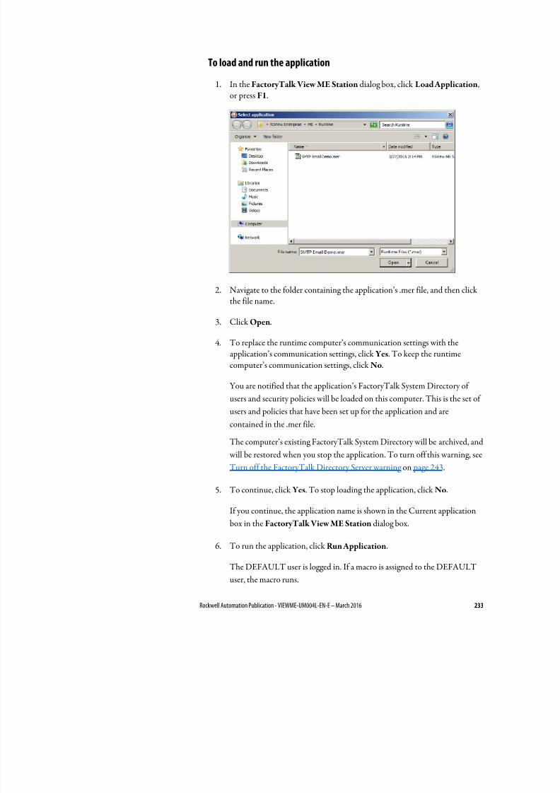
8/17/2019 FactoryTalk® View Machine Edition User's Guide
http://slidepdf.com/reader/full/factorytalk-view-machine-edition-users-guide 233/587
Rockwell Automation Publication - VIEWME-UM004L-EN-E – March 2016 233
To load and run the application
1. In the FactoryTalk View ME Station dialog box, click Load Application,or press F1.
2. Navigate to the folder containing the application’s .mer file, and then clickthe file name.
3.
Click Open.
4. To replace the runtime computer’s communication settings with theapplication’s communication settings, click Yes. To keep the runtime
computer’s communication settings, click No.
You are notified that the application’s FactoryTalk System Directory of
users and security policies will be loaded on this computer. This is the set of
users and policies that have been set up for the application and are
contained in the .mer file.
The computer’s existing FactoryTalk System Directory will be archived, and
will be restored when you stop the application. To turn off this warning, see
Turn off the FactoryTalk Directory Server warning on page 243.
5.
To continue, click Yes. To stop loading the application, click No.
If you continue, the application name is shown in the Current application
box in the FactoryTalk View ME Station dialog box.
6.
To run the application, click Run Application.
The DEFAULT user is logged in. If a macro is assigned to the DEFAULT
user, the macro runs.
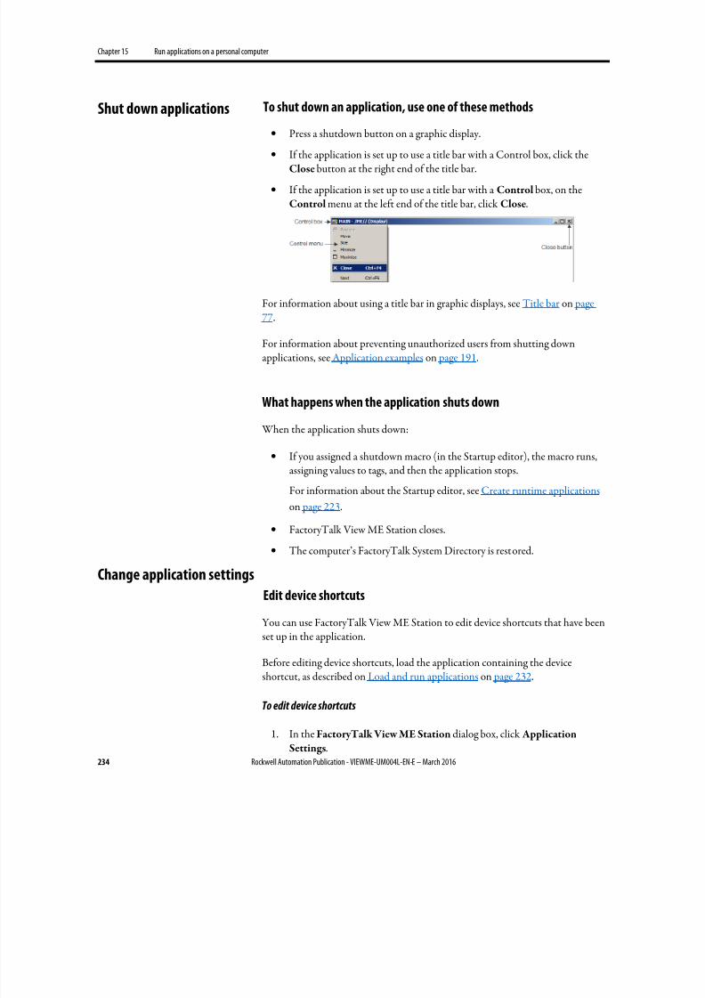
8/17/2019 FactoryTalk® View Machine Edition User's Guide
http://slidepdf.com/reader/full/factorytalk-view-machine-edition-users-guide 234/587
Chapter 15 Run applications on a personal computer
234 Rockwell Automation Publication - VIEWME-UM004L-EN-E – March 2016
To shut down an application, use one of these methods
• Press a shutdown button on a graphic display.
•
If the application is set up to use a title bar with a Control box, click theClose button at the right end of the title bar.
• If the application is set up to use a title bar with a Control box, on theControl menu at the left end of the title bar, click Close.
For information about using a title bar in graphic displays, see Title bar on page77.
For information about preventing unauthorized users from shutting downapplications, see Application examples on page 191.
What happens when the application shuts down
When the application shuts down:
• If you assigned a shutdown macro (in the Startup editor), the macro runs,assigning values to tags, and then the application stops.
For information about the Startup editor, see Create runtime applications
on page 223.
• FactoryTalk View ME Station closes.
• The computer’s FactoryTalk System Directory is restored.
Edit device shortcuts
You can use FactoryTalk View ME Station to edit device shortcuts that have beenset up in the application.
Before editing device shortcuts, load the application containing the deviceshortcut, as described on Load and run applications on page 232.
To edit device shortcuts
1. In the FactoryTalk View ME Station dialog box, click Application
Settings.
Shut down applications
Change application settings
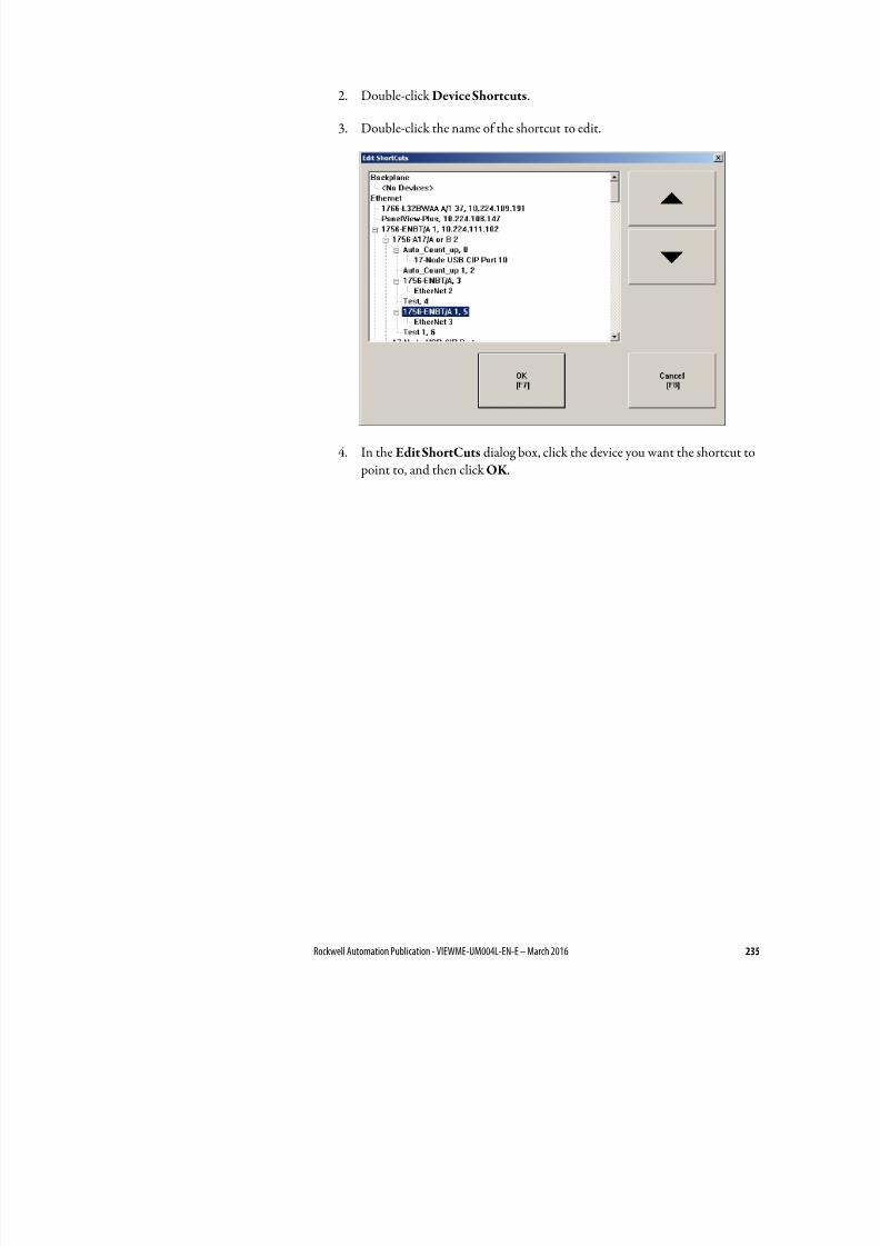
8/17/2019 FactoryTalk® View Machine Edition User's Guide
http://slidepdf.com/reader/full/factorytalk-view-machine-edition-users-guide 235/587
Rockwell Automation Publication - VIEWME-UM004L-EN-E – March 2016 235
2. Double-click Device Shortcuts.
3. Double-click the name of the shortcut to edit.
4. In the Edit ShortCuts dialog box, click the device you want the shortcut to point to, and then click OK .
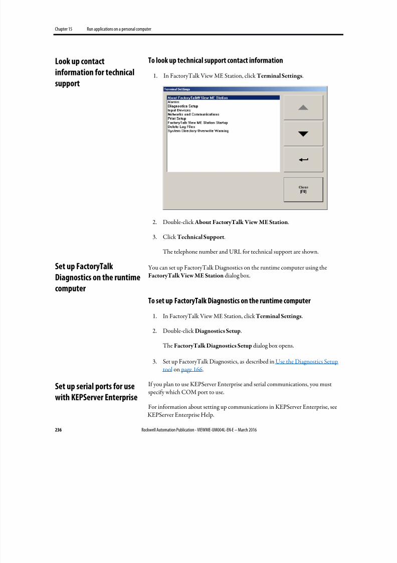
8/17/2019 FactoryTalk® View Machine Edition User's Guide
http://slidepdf.com/reader/full/factorytalk-view-machine-edition-users-guide 236/587
Chapter 15 Run applications on a personal computer
236 Rockwell Automation Publication - VIEWME-UM004L-EN-E – March 2016
To look up technical support contact information
1. In FactoryTalk View ME Station, click Terminal Settings.
2. Double-click About FactoryTalk View ME Station.
3. Click Technical Support.
The telephone number and URL for technical support are shown.
You can set up FactoryTalk Diagnostics on the runtime computer using theFactoryTalk View ME Station dialog box.
To set up FactoryTalk Diagnostics on the runtime computer
1. In FactoryTalk View ME Station, click Terminal Settings.
2. Double-click Diagnostics Setup.
The FactoryTalk Diagnostics Setup dialog box opens.
3. Set up FactoryTalk Diagnostics, as described in Use the Diagnostics Setuptool on page 166.
If you plan to use KEPServer Enterprise and serial communications, you mustspecify which COM port to use.
For information about setting up communications in KEPServer Enterprise, seeKEPServer Enterprise Help.
Look up contact
information for technical
support
Set up FactoryTalk
Diagnostics on the runtime
computer
Set up serial ports for use
with KEPServer Enterprise
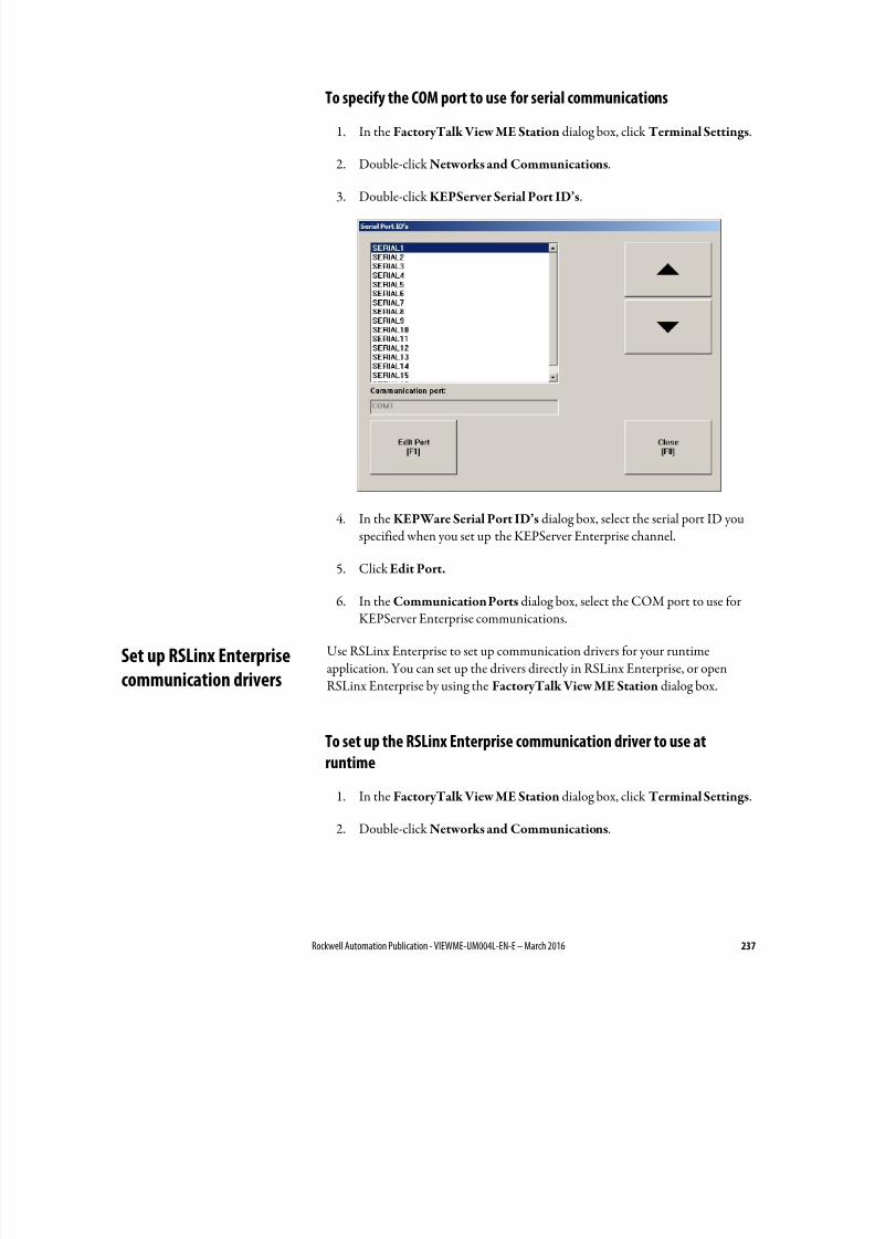
8/17/2019 FactoryTalk® View Machine Edition User's Guide
http://slidepdf.com/reader/full/factorytalk-view-machine-edition-users-guide 237/587
Rockwell Automation Publication - VIEWME-UM004L-EN-E – March 2016 237
To specify the COM port to use for serial communications
1. In the FactoryTalk View ME Station dialog box, click Terminal Settings.
2. Double-click Networks and Communications.
3.
Double-click KEPServer Serial Port ID’s.
4. In the KEPWare Serial Port ID’s dialog box, select the serial port ID youspecified when you set up the KEPServer Enterprise channel.
5. Click Edit Port.
6. In the Communication Ports dialog box, select the COM port to use forKEPServer Enterprise communications.
Use RSLinx Enterprise to set up communication drivers for your runtimeapplication. You can set up the drivers directly in RSLinx Enterprise, or openRSLinx Enterprise by using the FactoryTalk View ME Station dialog box.
To set up the RSLinx Enterprise communication driver to use at
runtime1. In the FactoryTalk View ME Station dialog box, click Terminal Settings.
2. Double-click Networks and Communications.
Set up RSLinx Enterprise
communication drivers
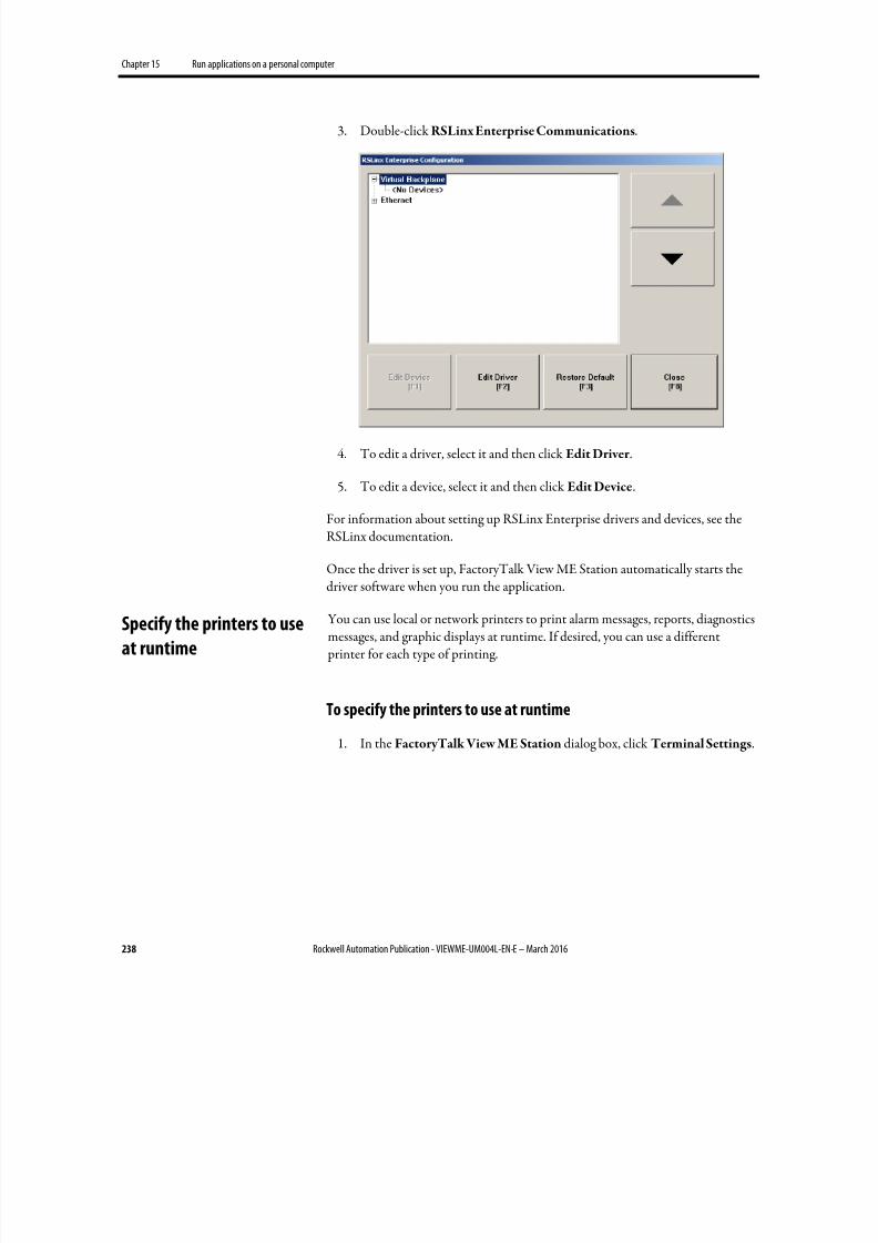
8/17/2019 FactoryTalk® View Machine Edition User's Guide
http://slidepdf.com/reader/full/factorytalk-view-machine-edition-users-guide 238/587
Chapter 15 Run applications on a personal computer
238 Rockwell Automation Publication - VIEWME-UM004L-EN-E – March 2016
3. Double-click RSLinx Enterprise Communications.
4. To edit a driver, select it and then click Edit Driver .
5. To edit a device, select it and then click Edit Device.
For information about setting up RSLinx Enterprise drivers and devices, see theRSLinx documentation.
Once the driver is set up, FactoryTalk View ME Station automatically starts thedriver software when you run the application.
You can use local or network printers to print alarm messages, reports, diagnosticsmessages, and graphic displays at runtime. If desired, you can use a different printer for each type of printing.
To specify the printers to use at runtime
1. In the FactoryTalk View ME Station dialog box, click Terminal Settings.
Specify the printers to use
at runtime
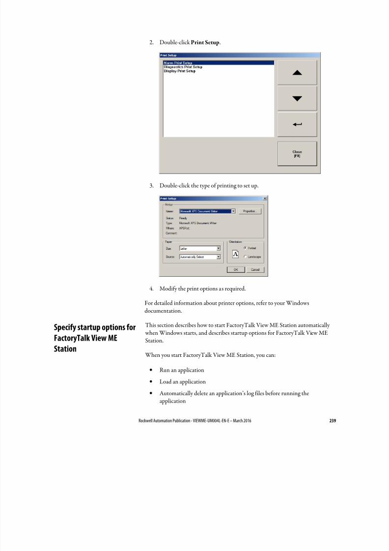
8/17/2019 FactoryTalk® View Machine Edition User's Guide
http://slidepdf.com/reader/full/factorytalk-view-machine-edition-users-guide 239/587
Rockwell Automation Publication - VIEWME-UM004L-EN-E – March 2016 239
2. Double-click Print Setup.
3. Double-click the type of printing to set up.
4. Modify the print options as required.
For detailed information about printer options, refer to your Windowsdocumentation.
This section describes how to start FactoryTalk View ME Station automatically when Windows starts, and describes startup options for FactoryTalk View ME
Station.
When you start FactoryTalk View ME Station, you can:
• Run an application
• Load an application
• Automatically delete an application’s log files before running theapplication
Specify startup options for
FactoryTalk View MEStation
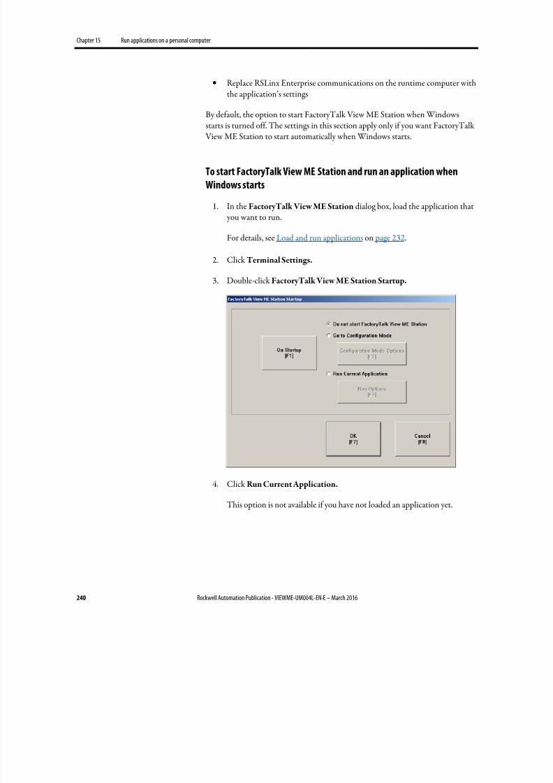
8/17/2019 FactoryTalk® View Machine Edition User's Guide
http://slidepdf.com/reader/full/factorytalk-view-machine-edition-users-guide 240/587
Chapter 15 Run applications on a personal computer
240 Rockwell Automation Publication - VIEWME-UM004L-EN-E – March 2016
• Replace RSLinx Enterprise communications on the runtime computer withthe application’s settings
By default, the option to start FactoryTalk View ME Station when Windowsstarts is turned off. The settings in this section apply only if you want FactoryTalk View ME Station to start automatically when Windows starts.
To start FactoryTalk View ME Station and run an application when
Windows starts
1. In the FactoryTalk View ME Station dialog box, load the application that you want to run.
For details, see Load and run applications on page 232.
2. Click Terminal Settings.
3. Double-click FactoryTalk View ME Station Startup.
4.
Click Run Current Application.
This option is not available if you have not loaded an application yet.
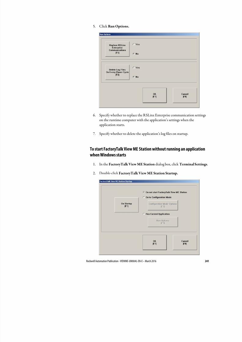
8/17/2019 FactoryTalk® View Machine Edition User's Guide
http://slidepdf.com/reader/full/factorytalk-view-machine-edition-users-guide 241/587
Rockwell Automation Publication - VIEWME-UM004L-EN-E – March 2016 241
5. Click Run Options.
6. Specify whether to replace the RSLinx Enterprise communication settingson the runtime computer with the application’s settings when theapplication starts.
7. Specify whether to delete the application’s log files on startup.
To start FactoryTalk View ME Station without running an application
when Windows starts
1. In the FactoryTalk View ME Station dialog box, click Terminal Settings.
2. Double-click FactoryTalk View ME Station Startup.
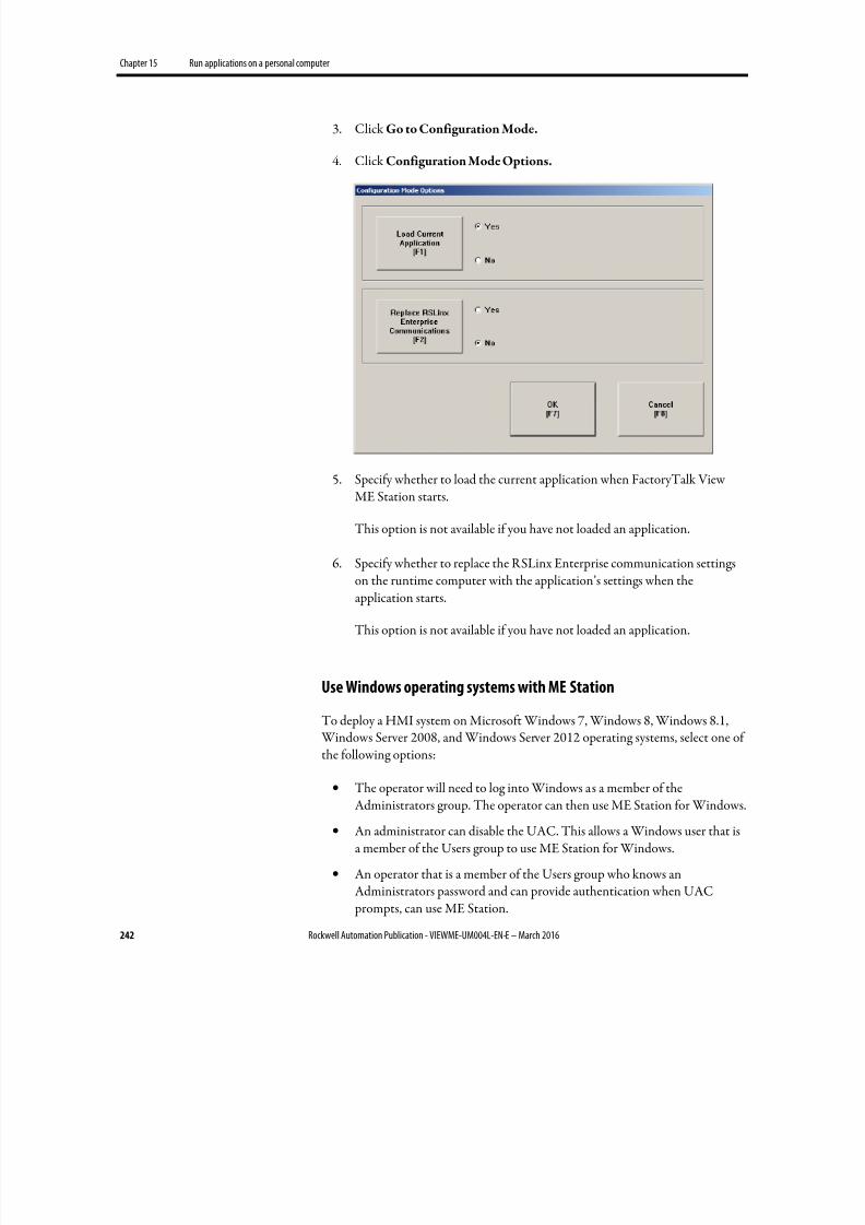
8/17/2019 FactoryTalk® View Machine Edition User's Guide
http://slidepdf.com/reader/full/factorytalk-view-machine-edition-users-guide 242/587
Chapter 15 Run applications on a personal computer
242 Rockwell Automation Publication - VIEWME-UM004L-EN-E – March 2016
3. Click Go to Configuration Mode.
4. Click Configuration Mode Options.
5. Specify whether to load the current application when FactoryTalk ViewME Station starts.
This option is not available if you have not loaded an application.
6.
Specify whether to replace the RSLinx Enterprise communication settingson the runtime computer with the application’s settings when theapplication starts.
This option is not available if you have not loaded an application.
Use Windows operating systems with ME Station
To deploy a HMI system on Microsoft Windows 7, Windows 8, Windows 8.1, Windows Server 2008, and Windows Server 2012 operating systems, select one of
the following options:
• The operator will need to log into Windows as a member of theAdministrators group. The operator can then use ME Station for Windows.
• An administrator can disable the UAC. This allows a Windows user that isa member of the Users group to use ME Station for Windows.
• An operator that is a member of the Users group who knows anAdministrators password and can provide authentication when UAC prompts, can use ME Station.
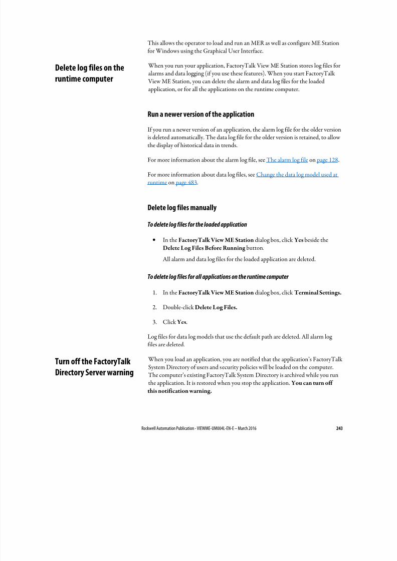
8/17/2019 FactoryTalk® View Machine Edition User's Guide
http://slidepdf.com/reader/full/factorytalk-view-machine-edition-users-guide 243/587
Rockwell Automation Publication - VIEWME-UM004L-EN-E – March 2016 243
This allows the operator to load and run an MER as well as configure ME Stationfor Windows using the Graphical User Interface.
When you run your application, FactoryTalk View ME Station stores log files foralarms and data logging (if you use these features). When you start FactoryTalk View ME Station, you can delete the alarm and data log files for the loaded
application, or for all the applications on the runtime computer.
Run a newer version of the application
If you run a newer version of an application, the alarm log file for the older versionis deleted automatically. The data log file for the older version is retained, to allowthe display of historical data in trends.
For more information about the alarm log file, see The alarm log file on page 128.
For more information about data log files, see Change the data log model used atruntime on page 483.
Delete log files manually
To delete log files for the loaded application
• In the FactoryTalk View ME Station dialog box, click Yes beside theDelete Log Files Before Running button.
All alarm and data log files for the loaded application are deleted.
To delete log files for all applications on the runtime computer
1. In the FactoryTalk View ME Station dialog box, click Terminal Settings.
2. Double-click Delete Log Files.
3. Click Yes.
Log files for data log models that use the default path are deleted. All alarm logfiles are deleted.
When you load an application, you are notified that the application’s FactoryTalkSystem Directory of users and security policies will be loaded on the computer.The computer’s existing FactoryTalk System Directory is archived while you runthe application. It is restored when you stop the application. You can turn off
this notification warning.
Delete log files on the
runtime computer
Turn off the FactoryTalk
Directory Server warning
8/17/2019 FactoryTalk® View Machine Edition User's Guide
http://slidepdf.com/reader/full/factorytalk-view-machine-edition-users-guide 244/587
Chapter 15 Run applications on a personal computer
244 Rockwell Automation Publication - VIEWME-UM004L-EN-E – March 2016
To turn off the overwrite warning
1. In the FactoryTalk View ME Station dialog box, click Terminal Settings.
2.
Double-click System Directory Overwrite Warning.
3. Click No.
Time, date, and number formats are used by these graphic objects:
• Numeric display
• Gauge
• Time and date display
• Trend
• Alarm banner
• Alarm list
The time and date formats are also used when printing the alarm history report(using the Print Alarm History button). The numeric and time and dateembedded variables also use number, time, and date formats.
All objects use the time, date, and number formats of the current applicationlanguage. For example, if the application language uses a comma for the decimalsymbol, numeric variables use a comma for the decimal symbol.
For information about using multiple languages, see Set up language switching on page 199.
Use the DeskLock tool to prevent users from switching to another softwareapplication or having access to the desktop at runtime.
This tool can have far-reaching effects on your operating system. The DeskLocktool can replace the standard Windows 7, Windows 8, Windows 8.1, WindowsServer 2008, or Windows Server 2012 operating system non-configured desktop with a customized desktop. The customized desktop is intended to prevent
operators from having access to other applications and operating system functionssuch as restarting Windows or shutting down tasks. You can also use the tool toset up an automatic Windows logon and to specify options such as which softwareapplications are allowed or not allowed to run on the computer.
Before using the tool, read the DeskLock Help completely.
Specify time, date, and
number formats
Use the DeskLock tool

8/17/2019 FactoryTalk® View Machine Edition User's Guide
http://slidepdf.com/reader/full/factorytalk-view-machine-edition-users-guide 245/587
Rockwell Automation Publication - VIEWME-UM004L-EN-E – March 2016 245
To open the DeskLock tool
• From Windows Start menu, select Programs > Rockwell Software >FactoryTalk View > Tools > DeskLock.
For details about using the tool, see the tool’s Help.

8/17/2019 FactoryTalk® View Machine Edition User's Guide
http://slidepdf.com/reader/full/factorytalk-view-machine-edition-users-guide 246/587
Chapter 15 Run applications on a personal computer
246 Rockwell Automation Publication - VIEWME-UM004L-EN-E – March 2016
8/17/2019 FactoryTalk® View Machine Edition User's Guide
http://slidepdf.com/reader/full/factorytalk-view-machine-edition-users-guide 247/587
Rockwell Automation Publication - VIEWME-UM004L-EN-E – March 2016 247
Chapter 16
Transfer applications to a MobileView,
PanelView Plus 7, PanelView Plus 6, PanelView
Plus, PanelView Plus Compact, or PanelView Plus
CE terminal
This chapter describes:
• Start FactoryTalk View ME Station
• Set up communication drivers to transfer applications to a MobileView,PanelView Plus 7, PanelView Plus 6, PanelView Plus, PanelView PlusCompact, or PanelView Plus CE terminal
• Transfer applications and Windows True Type font files to a terminal
• Upload applications from a terminal to the development computer
• Compare applications on the development computer with applications onthe terminal
For information about using your application at run time, see Use yourapplication on page 255
For information about using FactoryTalk View ME Station on the terminal,including setting up communications, printers, and input devices, see theterminal's User Manual .
Follow these steps to:
• Install printers and software on a MobileView, PanelView Plus 7,
PanelView Plus 6, PanelView Plus, PanelView Plus Compact, or PanelViewPlus CE terminal.
• Transfer an application to a MobileView, PanelView Plus 7, PanelView Plus6, PanelView Plus, PanelView Plus Compact, or PanelView Plus CEterminal.
For information about installing FactoryTalk View Machine Edition Station, seethe FactoryTalk View Machine Edition Installation Guide.
Steps for transferring
applications to a
MobileView, PanelViewPlus 7, PanelView Plus 6,
PanelView Plus, PanelView
Plus Compact, or PanelView
Plus CE terminal
8/17/2019 FactoryTalk® View Machine Edition User's Guide
http://slidepdf.com/reader/full/factorytalk-view-machine-edition-users-guide 248/587
Chapter 16 Transfer applications to a MobileView, PanelView Plus 7, PanelView Plus 6, PanelView Plus, PanelView Plus Compact, or PanelView Plus CE terminal
248 Rockwell Automation Publication - VIEWME-UM004L-EN-E – March 2016
Install printers and software on a MobileView, PanelView Plus 7,
PanelView Plus 6, PanelView Plus, PanelView Plus Compact, or
PanelView Plus CE terminal
1. If you will be printing displays, alarms, reports, or diagnostics messages,connect a printer to the USB or Network port.
2. If you are using KEPServer Enterprise, enable the driver you need on theterminal. For more information, see KEPServer Enterprise documentation.
For information about OPC data servers, see Set up communications on
page 81.
3. If your application uses third-party ActiveX objects, install and register the
Windows CE version of the objects on the terminal.
For information about ActiveX objects, see Use ActiveX objects on page
355.
Install printers on a PanelView Plus 7 or PanelView Plus 6 terminal
PanelView Plus 7 and PanelView Plus 6 terminals incorporate the JETCETPRINT solution for Microsoft Windows CE devices, supporting select Canon,Epson, Hewlett-Packard, and Brother printers. Plug-and-play installation issupported for these printers as well as manual installation if a suitable JETCET
print driver is available.
Print support is centrally managed and independent of the application. You canadd and configure a new printer from the desktop control panel. Printerconfigurations include the printer name, printer driver, port, and port-specific parameters. New configurations are retained through a power cycle.
PanelView Plus 7 and PanelView Plus 6 terminals support a wide range of printers.For a list of supported printers, see Answer ID 111636 in Rockwell AutomationKnowledgebase.
Install printers on a PanelView Plus terminal
PanelView Plus terminals support printing using the Microsoft Windows CEPCL3 printer driver, which is already installed on the terminal. Printing issupported for most laser and ink-jet printers. If you have problems printing, checkthat your printer is compatible with the PCL3 printer driver.
8/17/2019 FactoryTalk® View Machine Edition User's Guide
http://slidepdf.com/reader/full/factorytalk-view-machine-edition-users-guide 249/587
Transfer applications to a MobileView, PanelView Plus 7, PanelView Plus 6, PanelView Plus, PanelView Plus Compact, or PanelView Plus CE terminal Chapter 16
Rockwell Automation Publication - VIEWME-UM004L-EN-E – March 2016 249
Install printers on a MobileView terminal
The steps of installing printers on a MobileView terminal are similar with thesteps on a computer. For more information, see Specify the printers to use atruntime on page 238.
Transfer applications
1. On the MobileView, PanelView Plus 7, PanelView Plus 6, PanelView Plus,PanelView Plus Compact, or PanelView Plus CE terminal, startFactoryTalk View ME Station.
For more information, see Start FactoryTalk View Machine Edition on a
MobileView, PanelView Plus 7, PanelView Plus 6, PanelView Plus,PanelView Plus Compact, or PanelView Plus CE terminal on page 250.
2.
In FactoryTalk View ME Station, if you are transferring via a serialconnection, specify and set up the serial driver. If you are using Ethernet forthe transfer, you can skip this step.
For more information, see Specify the driver to use for the transfer on page
251.
3. On the development computer, if you are transferring via a serial
connection, set up the RSLinx Enterprise driver to use for the transfer. If you are using Ethernet for the transfer, you can skip this step.
For more information, see Specify the driver to use for the transfer on page
251.
4. Move the application to the MobileView, PanelView Plus 7, PanelView Plus6, PanelView Plus, PanelView Plus Compact, or PanelView Plus CEterminal terminal using ME Transfer Utility.
For more information, see Download applications and Windows True Type
fonts on page 252.
You can also transfer applications to the terminal using a flash card. Forinformation about this method, see the terminal's User Manual .
8/17/2019 FactoryTalk® View Machine Edition User's Guide
http://slidepdf.com/reader/full/factorytalk-view-machine-edition-users-guide 250/587
Chapter 16 Transfer applications to a MobileView, PanelView Plus 7, PanelView Plus 6, PanelView Plus, PanelView Plus Compact, or PanelView Plus CE terminal
250 Rockwell Automation Publication - VIEWME-UM004L-EN-E – March 2016
On a MobileView, PanelView Plus 7, PanelView Plus 6, PanelView Plus,PanelView Plus Compact, or PanelView Plus CE terminal, if FactoryTalk ViewMachine Edition Station does not start automatically when the terminal starts, you can start FactoryTalk View Machine Edition Station manually.
For information about specifying startup options for FactoryTalk View MachineEdition Station, see Specify startup options for FactoryTalk View ME Station on page 239.
Start FactoryTalk View Machine Edition Station on a PanelView Plus 7,
PanelView Plus 6, PanelView Plus, or PanelView Plus CE terminal
To start FactoryTalk View Machine Edition Station on a PanelView Plus 7,
PanelView Plus 6, PanelView Plus, or PanelView Plus CE terminal, do one ofthe following:
• On the desktop, double-click the shortcut icon FTView ME Station.
• In the Windows Explorer, double-click MERuntime.exe. Default locationfor this file is:
(PanelView Plus 7 and PanelView Plus 6) \Windows
(PanelView Plus and PanelView Plus CE) \Storage Card\Rockwell
Software\RSViewME
•
If Windows Start menu is available, from the Start menu, select Run. In theOpen box, type the path to the MERuntime.exe file.
• If Windows Start menu is available, from the Start menu, select Programs
> Rockwell Software > FactoryTalk View ME Station.
Start FactoryTalk View Machine Edition Station on a MobileView
terminal
To start FactoryTalk View Machine Edition Station on a MobileView
terminal, do one of the following:
• On the desktop, press the FTView ME Station icon
• In File Explorer , right-click MERuntime.exe and select Run as
administrator . The default location for the file is C:\Program Files
(x86)\Rockwell Software\RSView Enterprise\MERuntime.exe
Start FactoryTalk View
Machine Edition on a
MobileView, PanelViewPlus 7, PanelView Plus 6,
PanelView Plus, PanelView
Plus Compact, or PanelView
Plus CE terminal
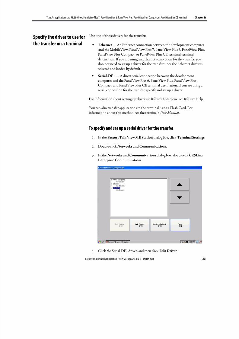
8/17/2019 FactoryTalk® View Machine Edition User's Guide
http://slidepdf.com/reader/full/factorytalk-view-machine-edition-users-guide 251/587
Transfer applications to a MobileView, PanelView Plus 7, PanelView Plus 6, PanelView Plus, PanelView Plus Compact, or PanelView Plus CE terminal Chapter 16
Rockwell Automation Publication - VIEWME-UM004L-EN-E – March 2016 251
Use one of these drivers for the transfer:
• Ethernet — An Ethernet connection between the development computerand the MobileView, PanelView Plus 7, PanelView Plus 6, PanelView Plus,PanelView Plus Compact, or PanelView Plus CE terminal terminaldestination. If you are using an Ethernet connection for the transfer, youdon not need to set up a driver for the transfer since the Ethernet driver isselected and loaded by default.
• Serial-DF1 — A direct serial connection between the developmentcomputer and the PanelView Plus 6, PanelView Plus, PanelView PlusCompact, and PanelView Plus CE terminal destination. If you are using aserial connection for the transfer, specify and set up a driver.
For information about setting up drivers in RSLinx Enterprise, see RSLinx Help.
You can also transfer applications to the terminal using a Flash Card. Forinformation about this method, see the terminal's User Manual .
To specify and set up a serial driver for the transfer
1. In the FactoryTalk View ME Station dialog box, click Terminal Settings.
2. Double-click Networks and Communications.
3. In the Networks and Communications dialog box, double-click RSLinx
Enterprise Communications.
4. Click the Serial-DF1 driver, and then click Edit Driver .
Specify the driver to use for
the transfer on a terminal

8/17/2019 FactoryTalk® View Machine Edition User's Guide
http://slidepdf.com/reader/full/factorytalk-view-machine-edition-users-guide 252/587
Chapter 16 Transfer applications to a MobileView, PanelView Plus 7, PanelView Plus 6, PanelView Plus, PanelView Plus Compact, or PanelView Plus CE terminal
252 Rockwell Automation Publication - VIEWME-UM004L-EN-E – March 2016
5. Select Use Auto-Configuration, and then click Edit.
6. In the dialog box that opens, select Yes, and then click OK .
Auto configuration works with most devices, including Logix5000 andPLC-5. If auto configuration is not successful for your device, return to
these steps, select No, and continue to step 7.
7. Set up the driver, and then click OK . If you are using auto configuration,skip this step.
On the development computer, set up the RSLinx Enterprise driver that you willuse to download your application to the MobileView, PanelView Plus 7,PanelView Plus 6, PanelView Plus, PanelView Plus Compact, or PanelView PlusCE terminal.
Use one of these drivers for the transfer:
• Serial-DF1 — Use for a serial transfer.
• Ethernet — Use with an Ethernet connection.
For information about setting up drivers in RSLinx Enterprise, see RSLinx Help.
On the development computer, do one of the following:
• From Windows Start menu, select All Programs > Rockwell Software >
FactoryTalk View > Tools > ME Transfer Utility
• In FactoryTalk View Studio, from the Tools menu, select Transfer Utility
• In FactoryTalk View Studio, on the Toolbar, click the Transfer Utility icon
For details about using the utility, see Help for ME Transfer Utility.
Use ME Transfer Utility to:
• Download a runtime application file (.mer) or True Type font file (.ttf or
.ttc) from the development computer (source) to a PanelView Plus 7,PanelView Plus 6, PanelView Plus, PanelView Plus Compact, or PanelViewPlus CE terminal (destination). A .ttf file contains a single font. A .ttc filecontains a collection of fonts.
• Download a runtime application file (.mer) from the developmentcomputer (source) to a MobileView terminal (destination).
For information about creating the runtime application file, see Create runtimeapplications on page 223.
Set up a driver for the
transfer on the
development computer
Start ME Transfer Utility on
the development computer
Download applications and
Windows True Type fonts
8/17/2019 FactoryTalk® View Machine Edition User's Guide
http://slidepdf.com/reader/full/factorytalk-view-machine-edition-users-guide 253/587
Transfer applications to a MobileView, PanelView Plus 7, PanelView Plus 6, PanelView Plus, PanelView Plus Compact, or PanelView Plus CE terminal Chapter 16
Rockwell Automation Publication - VIEWME-UM004L-EN-E – March 2016 253
About the download
You can download:
•
Multiple applications (one at a time) to the same terminal
• Applications while another application is running on the terminal
• A new copy of the application, which is running on the terminal, and usethe new application next time when you run the application on the terminal
If the download process fails or is cancelled, the application file will be deletedfrom the destination directories. Make a copy of the application file before youbegin and make sure there is enough storage space on the destination computer.
Serial downloads
To perform a serial download to a PanelView Plus 6, PanelView Plus, PanelViewPlus Compact, or PanelView Plus CE terminal, make sure the terminal isconnected to the development computer using the Allen-Bradley serial cable2711-NC13.
Use ME Transfer Utility to upload a runtime application file (.mer) from theMobileView, PanelView Plus 7, PanelView Plus 6, PanelView Plus, PanelViewPlus Compact, or PanelView Plus CE terminal to the development computer.
Any password changes that were made while the application was running are savedin the .mer file and will be uploaded.
If the upload process fails or is canceled, the application file will be deleted fromthe destination directory. Make sure there is enough storage space on thedestination computer.
About the upload
You can upload while an application is running on the runtime computer. You
can upload an existing copy of the application currently running on the runtimecomputer.
Serial uploads
To perform a serial upload from a PanelView Plus 6, PanelView Plus, PanelViewPlus Compact, or PanelView Plus CE terminal, make sure the terminal isconnected to the development computer using the Allen-Bradley serial cable2711-NC13.
Upload applications from
the MobileView, PanelView
Plus 7, PanelView Plus 6,
PanelView Plus, PanelView
Plus Compact, or PanelView
Plus CE terminal

8/17/2019 FactoryTalk® View Machine Edition User's Guide
http://slidepdf.com/reader/full/factorytalk-view-machine-edition-users-guide 254/587
Chapter 16 Transfer applications to a MobileView, PanelView Plus 7, PanelView Plus 6, PanelView Plus, PanelView Plus Compact, or PanelView Plus CE terminal
254 Rockwell Automation Publication - VIEWME-UM004L-EN-E – March 2016
You can also use the ME Transfer Utility tool to compare an application on thedevelopment computer with an application on the terminal. The comparison toolcan tell you whether the files are identical or different. The comparison tooldetects differences using a binary checksum. It is not possible to list individualdifferences between the files.
Compare applications
8/17/2019 FactoryTalk® View Machine Edition User's Guide
http://slidepdf.com/reader/full/factorytalk-view-machine-edition-users-guide 255/587
Rockwell Automation Publication - VIEWME-UM004L-EN-E – March 2016 255
Chapter 17
Use your application
This chapter describes:
• Log in and log out
• Change passwords
• Add a user or group and delete a user or group
•
Modify group membership• Unlock users
• Enable and disable users
• Change user properties
• Enter numeric and string values
• Change tag values
• Use electronic signature
• View tag data
• View alarms and messages
• View information about runtime communication errors
• Change languages
For information about navigating between displays, see Set up display navigation on page 215.
For information about navigating between and using the graphic objects in adisplay, see Set up how objects are used at runtime on page 403.
An application’s security configuration may contain native FactoryTalk Securityusers or Windows-linked users. Windows-linked user’s credentials are containedon either the local PC or in a domain. To support user authentication in a Windows domain, additional PanelView Plus terminal configuration is required.
FactoryTalk View ME 8.0 and later supports PanelView Plus 7, and PanelViewPlus 6 domain authentication against Windows Server 2012, Windows Server2008, and Windows Server 2003 domains in the following mechanism:
• LDAP (Lightweight Directory Access Protocol)
Log in to the application
Domain authentication
8/17/2019 FactoryTalk® View Machine Edition User's Guide
http://slidepdf.com/reader/full/factorytalk-view-machine-edition-users-guide 256/587
Chapter 17 Use your application
256 Rockwell Automation Publication - VIEWME-UM004L-EN-E – March 2016
• LDAP over SSL (Secure Sockets Layer)
For details, see Configure FactoryTalk View ME 8.0 and later terminals forDomain authentication on page 256.
FactoryTalk View ME releases prior to 8.0 support domain authentication against Windows Server 2000, and Windows Server 2003 domains. For details, seeConfigure FactoryTalk View ME prior to 8.0 terminals for Domainauthentication on page 260.
Configure FactoryTalk View ME 8.0 and later terminals for Domain
authentication
To configure LDAP settings on a FactoryTalk View ME 8.0 or later terminal
1. In the FactoryTalk View ME Station dialog box, click Terminal Settings.
2. Double-click Networks and Communications.
3. Double-click LDAP Configuration.
4. On FactoryTalk View ME 8.1 or later terminals, select one of the following Authentication Mode options:
• Use Windows and LDAP only authentication to use Windows
authentication mode to log in first. If Windows authentication fails,LDAP without SSL authentication mode will be used to log in.
• Use LDAP only authentication to use LDAP without SSLauthentication mode.
• Use LDAP over SSL authentication to use LDAP over SSLauthentication mode.
5. On FactoryTalk View ME 8.0 terminals, select one of the following Use
SSL options:
•
Yes to use LDAP over SSL authentication mode.
• No use LDAP without SSL authentication mode.
6. Do one of the following:
8/17/2019 FactoryTalk® View Machine Edition User's Guide
http://slidepdf.com/reader/full/factorytalk-view-machine-edition-users-guide 257/587
Use your application Chapter 17
Rockwell Automation Publication - VIEWME-UM004L-EN-E – March 2016 257
• In the Server FQDN box, enter FQDN (fully qualified domain name),for example, FTV1TT45.domain08r2.domain03.com.
Tip: FQDN is a DNS name that uniquely identifies the computer on the network. By default, it is
a concatenation of the host name, the primary DNS suffix, and a period.You can find the FQDN from the Network Identification tab of the the properties pagefor My Computer on the Domain server.
If SSL is enabled, you need to have the root certificate on your local terminal. For moreinformation about obtaining root certificate, see To obtain a root certificate on page 258.
• In the DNS-Style Domain Name box, enter the domain name, forexample, domain08r2.domain03.com.
The Port field is automatically filled.
7. On FactoryTalk View ME 8.1 or later terminals, select one of the followingGroup Membership options:
• Use user attribute (faster) - Security subsystem will only evaluatedomain group membership against the domain group(s) to which theuser explicitly belongs. Nested domain group membership will not beevaluated. This provides much faster domain authentication than theUse nested groups option. When using this option, it is critical thatthe domain group(s) to which the target user community belongsis(are) added to FactoryTalk Security explicitly, or added to a native
FactoryTalk group.• Use nested groups (slower) - Security subsystem will evaluate domain
group membership by querying the domain. The domain query returnsa list of all the groups to which the user belongs. User memberof
attribute will not be evaluated. This provides slower but more completeevaluation of a user’s domain group membership. When using thisoption, it is recommended that the domain group(s) to which the targetuser community belongs is(are) added to FactoryTalk Securityexplicitly, or added to a native FactoryTalk group.
For example, User A is a member of domain group Line1, and User A
memberof attribute explicitly lists Line1. User B is a member of domaingroup Shift3, and User B memberof attribute explicitly lists Shift3.
Shift3 is a subgroup of Line1. The HMI designer adds the domain
group Line1 to FactoryTalk Security, and adds and configures the
group in ME Runtime Security (A through P codes). On the PanelView
Plus 7, or PanelView Plus 6 terminal:
• When the HMI designer selects Use user attribute (faster), at
runtime, User A can successfully authenticate; but User B cannot
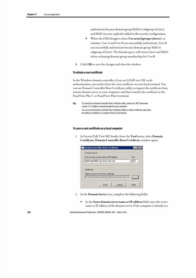
8/17/2019 FactoryTalk® View Machine Edition User's Guide
http://slidepdf.com/reader/full/factorytalk-view-machine-edition-users-guide 258/587
Chapter 17 Use your application
258 Rockwell Automation Publication - VIEWME-UM004L-EN-E – March 2016
authenticate because domain group Shift3 is subgroup of Line1,
and Shift3 was not explicitly added to the security configuration.
• When the HMI designer selects Use nested groups (slower), at
runtime, User A and User B can successfully authenticate. User Bcan successfully authenticate because domain group Shift3 is
subgroup of Line1. The domain query will return Line1 and Shift3
when evaluating domain group membership for User B.
8. Click OK to save the changes and close the window.
To obtain a root certificate
In the Windows domain controller, if you use LDAP over SSL to doauthentication, you need to have the root certificate on your local terminal. Youcan use Domain Controller Root Certificate utility to import the certificate fromremote domain server to your computer, and then transfer the certificate to thePanelView Plus 7, or PanelView Plus 6 terminal.
Tip: To correctly run Domain Controller Root Certificate utility, make sure .NET Frameworkversion 3.5 or higher is already installed on your computer.
You can use the Domain Controller Root Certificate utility to obtain certificates only whenthe utility is installed on a computer that is in the domain.
To save a root certificate on a local computer
1. In FactoryTalk View ME Studio, from the Tool menu, select DomainCertificate. Domain Controller Root Certificate window opens.
2. In the Domain Server area, complete the following fields:
• In the Enter domain server name or IP address field, enter the servername or IP address of the domain server. If the computer is already in a
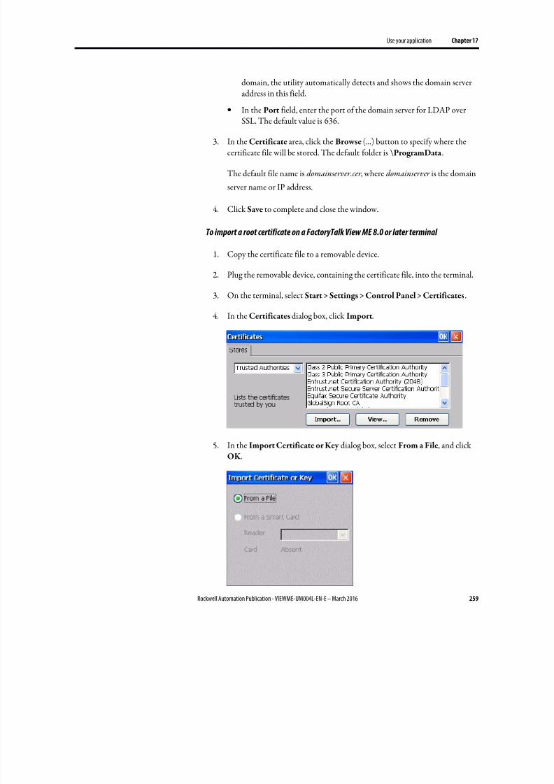
8/17/2019 FactoryTalk® View Machine Edition User's Guide
http://slidepdf.com/reader/full/factorytalk-view-machine-edition-users-guide 259/587
Use your application Chapter 17
Rockwell Automation Publication - VIEWME-UM004L-EN-E – March 2016 259
domain, the utility automatically detects and shows the domain serveraddress in this field.
• In the Port field, enter the port of the domain server for LDAP over
SSL. The default value is 636.
3. In the Certificate area, click the Browse (...) button to specify where thecertificate file will be stored. The default folder is \ProgramData.
The default file name is domainserver.cer , where domainserver is the domain
server name or IP address.
4. Click Save to complete and close the window.
To import a root certificate on a FactoryTalk View ME 8.0 or later terminal
1. Copy the certificate file to a removable device.
2. Plug the removable device, containing the certificate file, into the terminal.
3. On the terminal, select Start > Settings > Control Panel > Certificates.
4. In the Certificates dialog box, click Import.
5. In the Import Certificate or Key dialog box, select From a File, and clickOK .
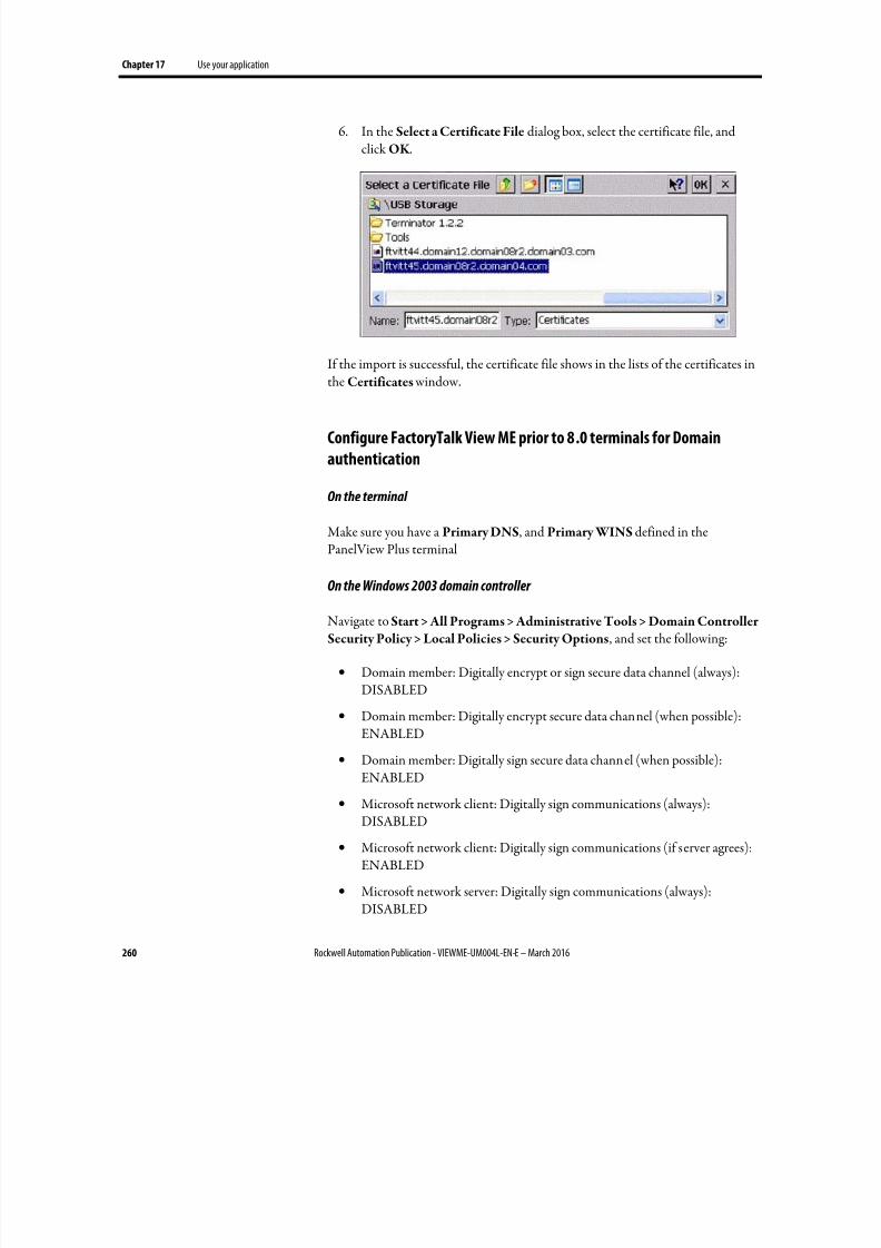
8/17/2019 FactoryTalk® View Machine Edition User's Guide
http://slidepdf.com/reader/full/factorytalk-view-machine-edition-users-guide 260/587
Chapter 17 Use your application
260 Rockwell Automation Publication - VIEWME-UM004L-EN-E – March 2016
6. In the Select a Certificate File dialog box, select the certificate file, andclick OK .
If the import is successful, the certificate file shows in the lists of the certificates in
the Certificates window.
Configure FactoryTalk View ME prior to 8.0 terminals for Domain
authentication
On the terminal
Make sure you have a Primary DNS, and Primary WINS defined in thePanelView Plus terminal
On the Windows 2003 domain controller
Navigate to Start > All Programs > Administrative Tools > Domain ControllerSecurity Policy > Local Policies > Security Options, and set the following:
• Domain member: Digitally encrypt or sign secure data channel (always):DISABLED
• Domain member: Digitally encrypt secure data channel (when possible):ENABLED
• Domain member: Digitally sign secure data channel (when possible):
ENABLED
• Microsoft network client: Digitally sign communications (always):DISABLED
• Microsoft network client: Digitally sign communications (if server agrees):ENABLED
• Microsoft network server: Digitally sign communications (always):DISABLED
8/17/2019 FactoryTalk® View Machine Edition User's Guide
http://slidepdf.com/reader/full/factorytalk-view-machine-edition-users-guide 261/587
Use your application Chapter 17
Rockwell Automation Publication - VIEWME-UM004L-EN-E – March 2016 261
• Microsoft network server: Digitally sign communications (if client agrees):ENABLED
• Network security: LAN Manager Authentication Level: Send LM &
NTLM - use NTLM v2 session security if negotiated
• Network security: LDAP client signing requirements: Negotiate Signing
To access network resources (printers, network shares), it is necessary to provideauthentication credentials for the PanelView Plus 7, PanelView Plus 6, PanelViewPlus, PanelView Plus Compact, or PanelView Plus CE terminal. These credentialsare independent of the currently logged in user in the HMI application.
To provide access to network resources when using a PanelView Plus 7,
PanelView Plus 6, PanelView Plus, PanelView Plus Compact, orPanelView Plus CE terminal
1. In the FactoryTalk View ME Station dialog box, click Terminal Settings.
2. Double-click Networks and Communications.
3. Double-click Network Connections.
4. Double-click Network Identification.
5. Type a user name, password, and domain name, and then click OK .
Users log in using the Login button. The Login button opens a dialog box thatallows the user to enter credentials.
To log in, both the Runtime Security and FactoryTalk Security configurationmust contain the individual user account, or a group of which the user account is amember.
For information about setting up user accounts and passwords, see Set up security on page 175.
Tip: When adding users and groups to FactoryTalk security, it is im portant to remember that auser cannot log in to the running application unless the user or group is configured inRuntime Security.
Access network resources
from a terminal
Log in to the application
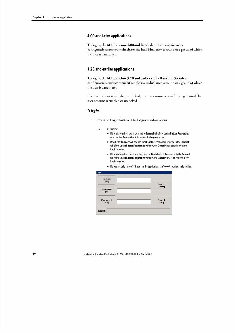
8/17/2019 FactoryTalk® View Machine Edition User's Guide
http://slidepdf.com/reader/full/factorytalk-view-machine-edition-users-guide 262/587
Chapter 17 Use your application
262 Rockwell Automation Publication - VIEWME-UM004L-EN-E – March 2016
4.00 and later applications
To log in, the ME Runtime 4.00 and later tab in Runtime Security
configuration must contain either the individual user account, or a group of whichthe user is a member.
3.20 and earlier applications
To log in, the ME Runtime 3.20 and earlier tab in Runtime Security configuration must contain either the individual user account, or a group of whichthe user is a member.
If a user account is disabled, or locked, the user cannot successfully log in until theuser account is enabled or unlocked
To log in
1. Press the Login button. The Login window opens.
Tip: At runtime:
• If the Visible check box is clear in the General tab of the Login Button Properties window, the Domain box is hidden in the Login window.
• If both the Visible check box and the Disable check box are selected in the General tab of the Login Button Properties window, the Domain box is read-only in theLogin window.
•
If the Visible check box is selected, and the Disable check box is clear in the General tab of the Login Button Properties window, the Domain box can be edited in theLogin window.
• If there are only FactoryTalk users in the application, the Domain box is usually hidden.
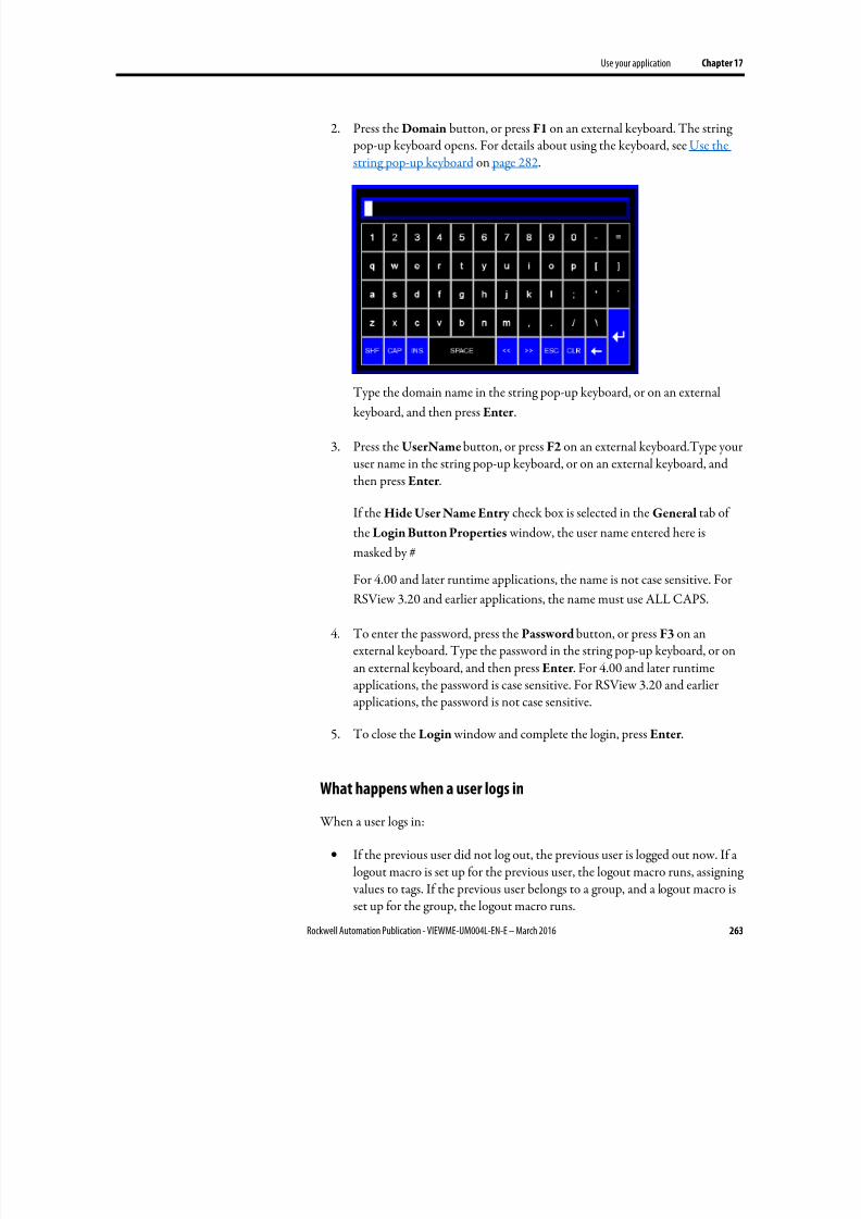
8/17/2019 FactoryTalk® View Machine Edition User's Guide
http://slidepdf.com/reader/full/factorytalk-view-machine-edition-users-guide 263/587
Use your application Chapter 17
Rockwell Automation Publication - VIEWME-UM004L-EN-E – March 2016 263
2. Press the Domain button, or press F1 on an external keyboard. The string pop-up keyboard opens. For details about using the keyboard, see Use thestring pop-up keyboard on page 282.
Type the domain name in the string pop-up keyboard, or on an external
keyboard, and then press Enter .
3. Press the UserName button, or press F2 on an external keyboard.Type youruser name in the string pop-up keyboard, or on an external keyboard, andthen press Enter .
If the Hide User Name Entry check box is selected in the General tab of
the Login Button Properties window, the user name entered here is
masked by #
For 4.00 and later runtime applications, the name is not case sensitive. For
RSView 3.20 and earlier applications, the name must use ALL CAPS.
4. To enter the password, press the Password button, or press F3 on anexternal keyboard. Type the password in the string pop-up keyboard, or onan external keyboard, and then press Enter . For 4.00 and later runtimeapplications, the password is case sensitive. For RSView 3.20 and earlierapplications, the password is not case sensitive.
5. To close the Login window and complete the login, press Enter .
What happens when a user logs in
When a user logs in:
• If the previous user did not log out, the previous user is logged out now. If alogout macro is set up for the previous user, the logout macro runs, assigning values to tags. If the previous user belongs to a group, and a logout macro isset up for the group, the logout macro runs.
8/17/2019 FactoryTalk® View Machine Edition User's Guide
http://slidepdf.com/reader/full/factorytalk-view-machine-edition-users-guide 264/587
Chapter 17 Use your application
264 Rockwell Automation Publication - VIEWME-UM004L-EN-E – March 2016
• The new user is logged in.
• If a login macro is set up for the new user, the macro runs, assigning valuesto tags. If the new user belongs to a group, and a login macro is set up for the
group, the login macro runs.
Problems with logging in
Login is unsuccessful under these circumstances:
• If the graphic display changes remotely before the user has finished loggingin, the login is cancelled.
• If the entered user name does not match a user account configured inRuntime Security
• If the entered user name is not a member of a group configured in Runtime
Security .
• If the entered user password does not match the user account passwordconfigured in Runtime Security .
• If the user account is disabled or locked
• If a PanelView Plus 7, PanelView Plus 6, PanelView Plus, PanelView PlusCompact, or PanelView Plus CE terminal's time is not synchronized withthe domain controller, domain users cannot log in on the terminal. Toenable the users to log in, synchronize the terminal’s time with the domaincontroller.
You can use the Password button to change password at runtime. Any passwordchanges made at runtime are saved in the .mer file.
The Password button supports two modes of runtime operations:
• Allows the user to modify their own password
• Allows the user to modify any user password
Tip: When designing the application in FactoryTalk View Studio, you must consider which users
and groups can access this button, and how to control that access.
The Password button operational mode is configured in FactoryTalk View Studio,and cannot be changed at runtime.
Change passwords
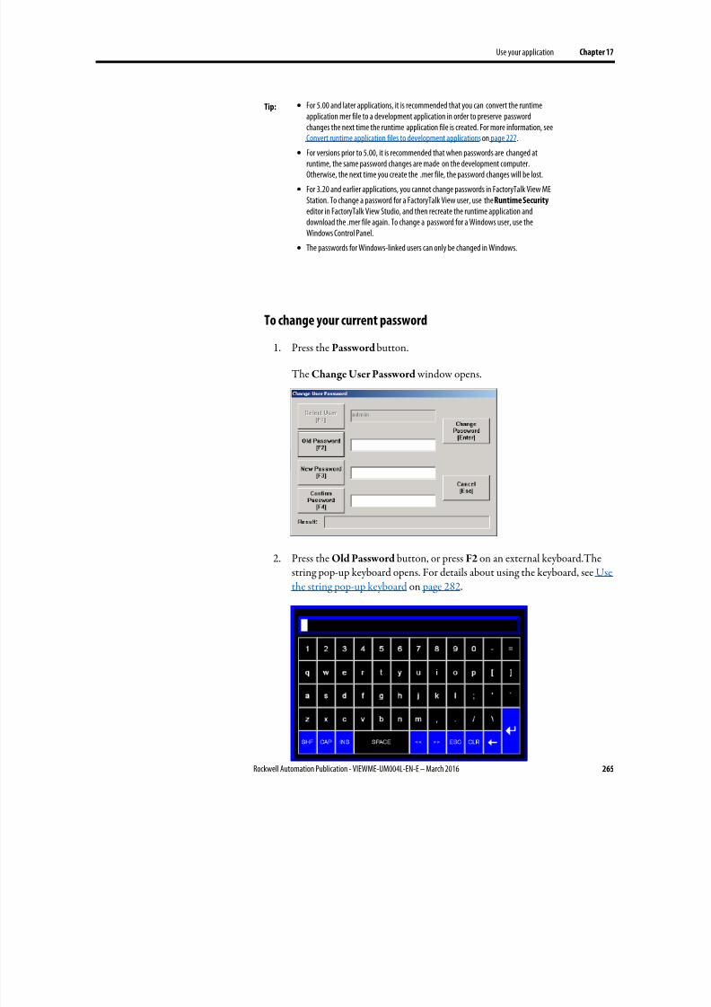
8/17/2019 FactoryTalk® View Machine Edition User's Guide
http://slidepdf.com/reader/full/factorytalk-view-machine-edition-users-guide 265/587
Use your application Chapter 17
Rockwell Automation Publication - VIEWME-UM004L-EN-E – March 2016 265
Tip: • For 5.00 and later applications, it is recommended that you can convert the runtimeapplication mer file to a development application in order to preserve passwordchanges the next time the runtime application file is created. For more information, seeConvert runtime application files to development applications on page 227.
•
For versions prior to 5.00, it is recommended that when passwords are changed atruntime, the same password changes are made on the development computer.Otherwise, the next time you create the .mer file, the password changes will be lost.
• For 3.20 and earlier applications, you cannot change passwords in FactoryTalk View MEStation. To change a password for a FactoryTalk View user, use the Runtime Security editor in FactoryTalk View Studio, and then recreate the runtime application anddownload the .mer file again. To change a password for a Windows user, use theWindows Control Panel.
• The passwords for Windows-linked users can only be changed in Windows.
To change your current password
1. Press the Password button.
The Change User Password window opens.
2. Press the Old Password button, or press F2 on an external keyboard.Thestring pop-up keyboard opens. For details about using the keyboard, see Usethe string pop-up keyboard on page 282.
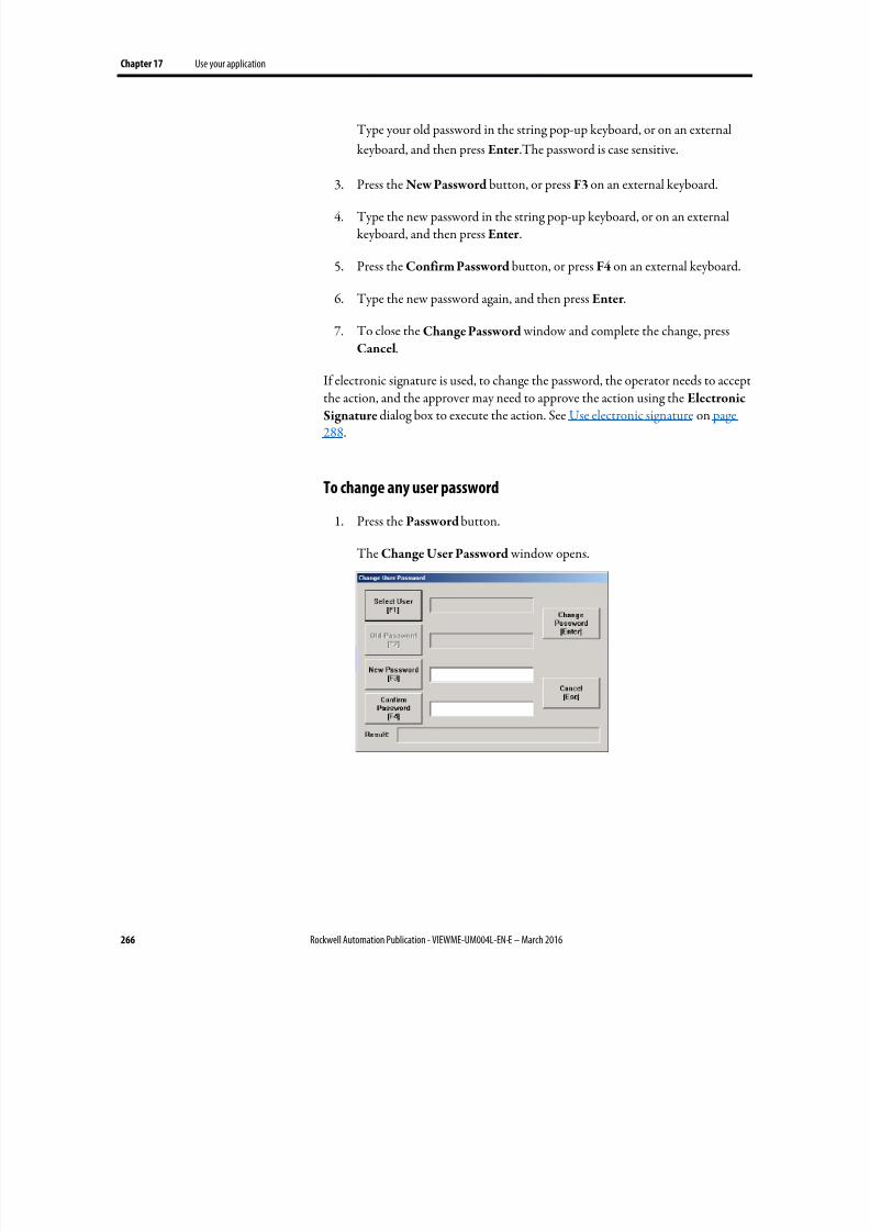
8/17/2019 FactoryTalk® View Machine Edition User's Guide
http://slidepdf.com/reader/full/factorytalk-view-machine-edition-users-guide 266/587
Chapter 17 Use your application
266 Rockwell Automation Publication - VIEWME-UM004L-EN-E – March 2016
Type your old password in the string pop-up keyboard, or on an external
keyboard, and then press Enter .The password is case sensitive.
3.
Press the New Password button, or press F3 on an external keyboard.
4. Type the new password in the string pop-up keyboard, or on an externalkeyboard, and then press Enter .
5. Press the Confirm Password button, or press F4 on an external keyboard.
6. Type the new password again, and then press Enter .
7.
To close the Change Password window and complete the change, pressCancel.
If electronic signature is used, to change the password, the operator needs to acceptthe action, and the approver may need to approve the action using the Electronic
Signature dialog box to execute the action. See Use electronic signature on page288.
To change any user password
1. Press the Password button.
The Change User Password window opens.
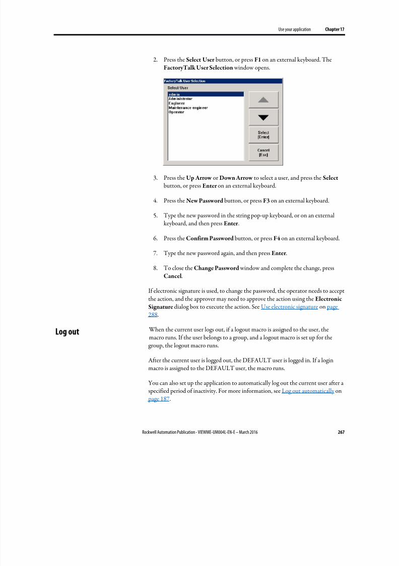
8/17/2019 FactoryTalk® View Machine Edition User's Guide
http://slidepdf.com/reader/full/factorytalk-view-machine-edition-users-guide 267/587
Use your application Chapter 17
Rockwell Automation Publication - VIEWME-UM004L-EN-E – March 2016 267
2. Press the Select User button, or press F1 on an external keyboard. TheFactoryTalk User Selection window opens.
3.
Press the Up Arrow or Down Arrow to select a user, and press the Select button, or press Enter on an external keyboard.
4. Press the New Password button, or press F3 on an external keyboard.
5. Type the new password in the string pop-up keyboard, or on an externalkeyboard, and then press Enter .
6. Press the Confirm Password button, or press F4 on an external keyboard.
7. Type the new password again, and then press Enter .
8. To close the Change Password window and complete the change, pressCancel.
If electronic signature is used, to change the password, the operator needs to acceptthe action, and the approver may need to approve the action using the Electronic
Signature dialog box to execute the action. See Use electronic signature on page288.
When the current user logs out, if a logout macro is assigned to the user, themacro runs. If the user belongs to a group, and a logout macro is set up for thegroup, the logout macro runs.
After the current user is logged out, the DEFAULT user is logged in. If a loginmacro is assigned to the DEFAULT user, the macro runs.
You can also set up the application to automatically log out the current user after aspecified period of inactivity. For more information, see Log out automatically on page 187.
Log out
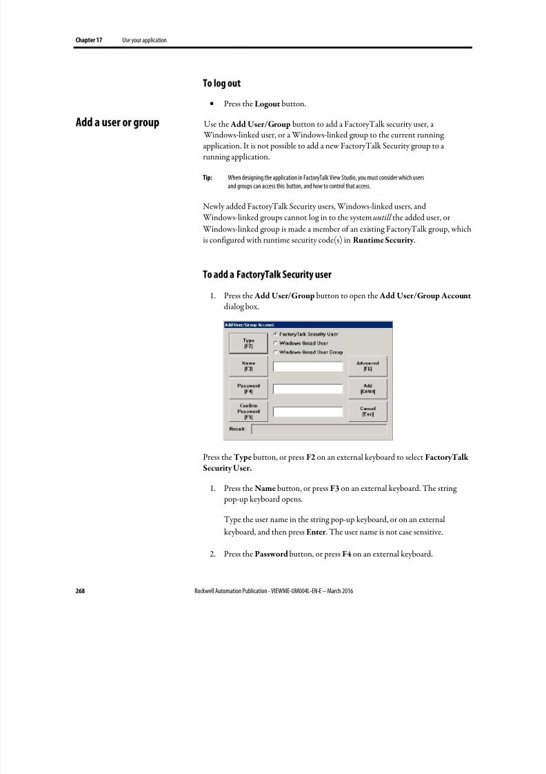
8/17/2019 FactoryTalk® View Machine Edition User's Guide
http://slidepdf.com/reader/full/factorytalk-view-machine-edition-users-guide 268/587
Chapter 17 Use your application
268 Rockwell Automation Publication - VIEWME-UM004L-EN-E – March 2016
To log out
• Press the Logout button.
Use the Add User/Group button to add a FactoryTalk security user, a Windows-linked user, or a Windows-linked group to the current runningapplication. It is not possible to add a new FactoryTalk Security group to arunning application.
Tip: When designing the application in FactoryTalk View Studio, you must consider which usersand groups can access this button, and how to control that access.
Newly added FactoryTalk Security users, Windows-linked users, and Windows-linked groups cannot log in to the system untill the added user, or
Windows-linked group is made a member of an existing FactoryTalk group, which
is configured with runtime security code(s) in Runtime Security .
To add a FactoryTalk Security user
1. Press the Add User/Group button to open the Add User/Group Account dialog box.
Press the Type button, or press F2 on an external keyboard to select FactoryTalk
Security User.
1. Press the Name button, or press F3 on an external keyboard. The string pop-up keyboard opens.
Type the user name in the string pop-up keyboard, or on an external
keyboard, and then press Enter . The user name is not case sensitive.
2. Press the Password button, or press F4 on an external keyboard.
Add a user or group
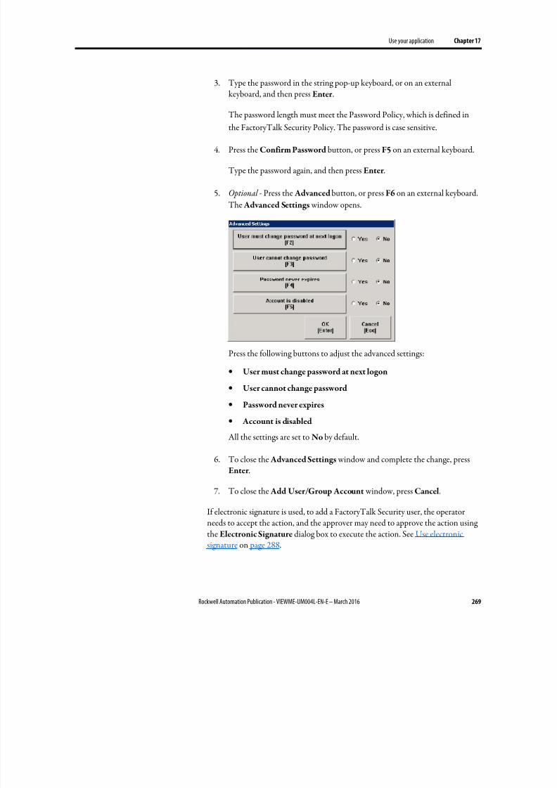
8/17/2019 FactoryTalk® View Machine Edition User's Guide
http://slidepdf.com/reader/full/factorytalk-view-machine-edition-users-guide 269/587
Use your application Chapter 17
Rockwell Automation Publication - VIEWME-UM004L-EN-E – March 2016 269
3. Type the password in the string pop-up keyboard, or on an externalkeyboard, and then press Enter .
The password length must meet the Password Policy, which is defined in
the FactoryTalk Security Policy. The password is case sensitive.
4. Press the Confirm Password button, or press F5 on an external keyboard.
Type the password again, and then press Enter .
5. Optional - Press the Advanced button, or press F6 on an external keyboard.
The Advanced Settings window opens.
Press the following buttons to adjust the advanced settings:
•
User must change password at next logon
• User cannot change password
• Password never expires
• Account is disabled
All the settings are set to No by default.
6. To close the Advanced Settings window and complete the change, pressEnter .
7.
To close the Add User/Group Account window, press Cancel.
If electronic signature is used, to add a FactoryTalk Security user, the operatorneeds to accept the action, and the approver may need to approve the action usingthe Electronic Signature dialog box to execute the action. See Use electronicsignature on page 288.
8/17/2019 FactoryTalk® View Machine Edition User's Guide
http://slidepdf.com/reader/full/factorytalk-view-machine-edition-users-guide 270/587
Chapter 17 Use your application
270 Rockwell Automation Publication - VIEWME-UM004L-EN-E – March 2016
To add a Windows-linked user or group
1. Press the Add User/Group button to open the Add User/Group Account
dialog box.
2. Press the Type button, or press F2 on an external keyboard to select Windows-linked User , or Windows-linked User Group.
When adding a Windows-linked user, or a Windows-linked user group, the
system will verify whether the user or group exists in the Windows domain,
Windows User Accounts. If the user or group does not exist in the
Windows domain, Windows User Accounts, it cannot be added.
3. Press the Name button, or press F3 on an external keyboard. The string
pop-up keyboard opens.
Type the user name in the string pop-up keyboard, or on an external
keyboard, and then press Enter to save. The user name is not case sensitive.
Tip: On the PanelView Plus 7 and PanelView Plus 6 terminals, there is a five-mi nute thresholdwhen adding a Windows-linked user, or a Windows-linked user group.
When you add a Windows-linked user, or a Windows-linked user group for the first time, awindow prompts you to enter an authorized user name and password.
Within five minutes after a Windows-linked user, or a Windows-linked user group issuccessfully added, you can add another Windows-linked user, or Windows-linked usergroup without entering an authorized user name and password.
Beyond five minutes after a Windows-linked user, or a Windows-linked user group is
successfully added, a window will prompt you to enter an authorized user name andpassword again before you can add another Windows-linked user, or Windows-linked usergroup.
4. To close the Add User/Group Account window, press Cancel.
If electronic signature is used, to add a Windows-linked user or group, theoperator needs to accept the action, and the approver may need to approve theaction using the Electronic Signature dialog box to execute the action. See Useelectronic signature on page 288.
The administrator can use the Delete User/Group button to delete a FactoryTalk
security user, a Windows-linked user, or a Windows-linked group from thecurrent running application. It is not possible to delete a FactoryTalk Securitygroup from the running application.
Tip: When designing the application in FactoryTalk View Studio, you must consider which usersand groups can access this button, and how to control that access.
If a Windows-linked user group or a Windows-linked user is deleted, the group oruser will be removed from the current running application, but will not beremoved from Windows.
Delete a user or group
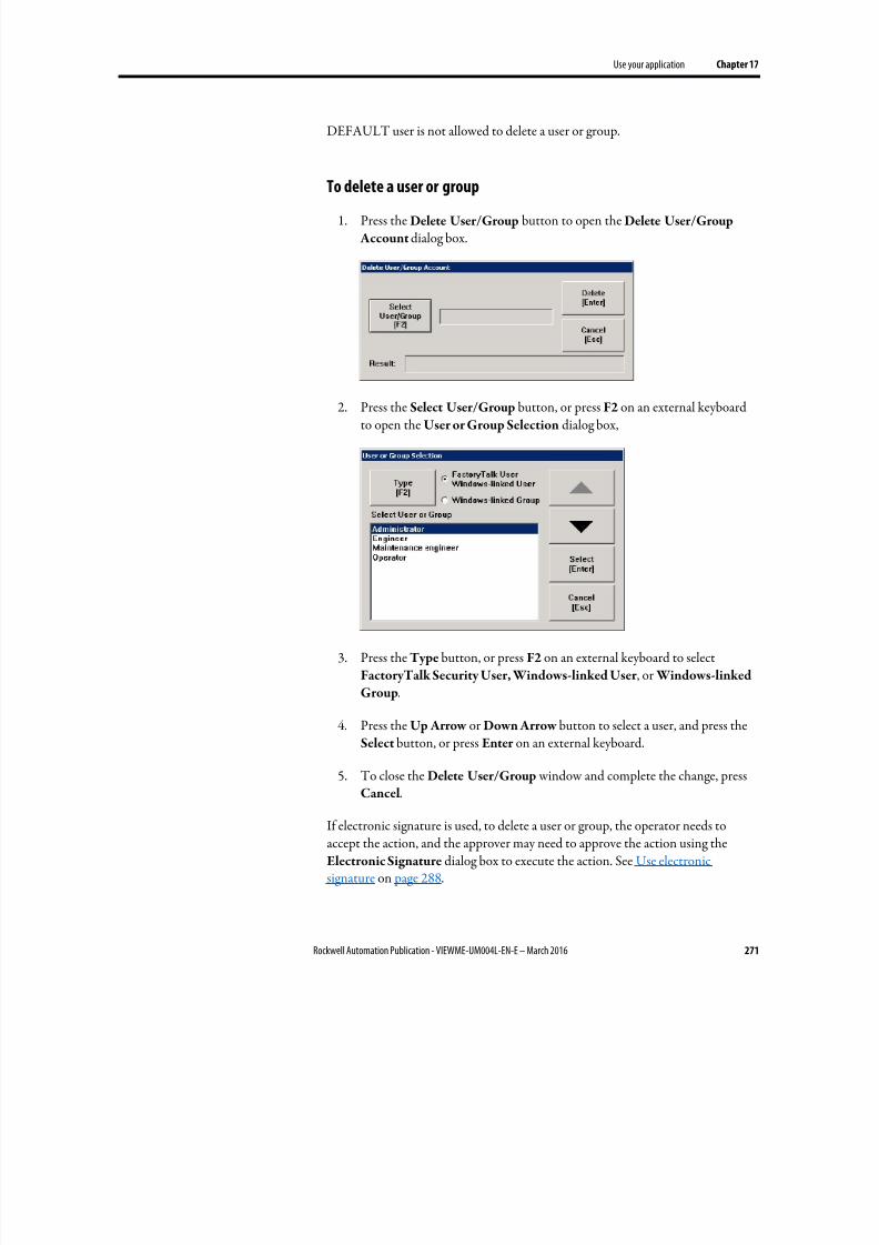
8/17/2019 FactoryTalk® View Machine Edition User's Guide
http://slidepdf.com/reader/full/factorytalk-view-machine-edition-users-guide 271/587
Use your application Chapter 17
Rockwell Automation Publication - VIEWME-UM004L-EN-E – March 2016 271
DEFAULT user is not allowed to delete a user or group.
To delete a user or group1.
Press the Delete User/Group button to open the Delete User/Group Account dialog box.
2. Press the Select User/Group button, or press F2 on an external keyboardto open the User or Group Selection dialog box,
3. Press the Type button, or press F2 on an external keyboard to selectFactoryTalk Security User, Windows-linked User , or Windows-linked
Group.
4. Press the Up Arrow or Down Arrow button to select a user, and press theSelect button, or press Enter on an external keyboard.
5.
To close the Delete User/Group window and complete the change, pressCancel.
If electronic signature is used, to delete a user or group, the operator needs toaccept the action, and the approver may need to approve the action using theElectronic Signature dialog box to execute the action. See Use electronicsignature on page 288.
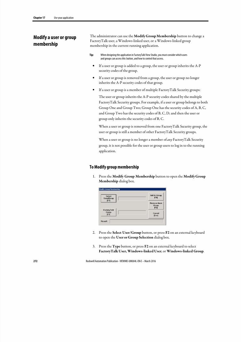
8/17/2019 FactoryTalk® View Machine Edition User's Guide
http://slidepdf.com/reader/full/factorytalk-view-machine-edition-users-guide 272/587
Chapter 17 Use your application
272 Rockwell Automation Publication - VIEWME-UM004L-EN-E – March 2016
The administrator can use the Modify Group Membership button to change aFactoryTalk user, a Windows-linked user, or a Windows-linked groupmembership in the current running application.
Tip: When designing the application in FactoryTalk View Studio, you must consider which usersand groups can access this button, and how to control that access.
• If a user or group is added to a group, the user or group inherits the A-Psecurity codes of the group.
• If a user or group is removed from a group, the user or group no longerinherits the A-P security codes of that group.
• If a user or group is a member of multiple FactoryTalk Security groups:
The user or group inherits the A-P security codes shared by the multiple
FactoryTalk Security groups. For example, if a user or group belongs to both
Group One and Group Two; Group One has the security codes of A, B, C,
and Group Two has the security codes of B, C, D; and then the user or
group only inherits the security codes of B, C.
When a user or group is removed from one FactoryTalk Security group, the
user or group is still a member of other FactoryTalk Security groups.
When a user or group is no longer a member of any FactoryTalk Security
group, it is not possible for the user or group users to log in to the running
application.
To Modify group membership
1. Press the Modify Group Membership button to open the Modify GroupMembership dialog box.
2. Press the Select User/Group button, or press F2 on an external keyboardto open the User or Group Selection dialog box.
3. Press the Type button, or press F2 on an external keyboard to selectFactoryTalk User, Windows-linked User , or Windows-linked Group.
Modify a user or group
membership
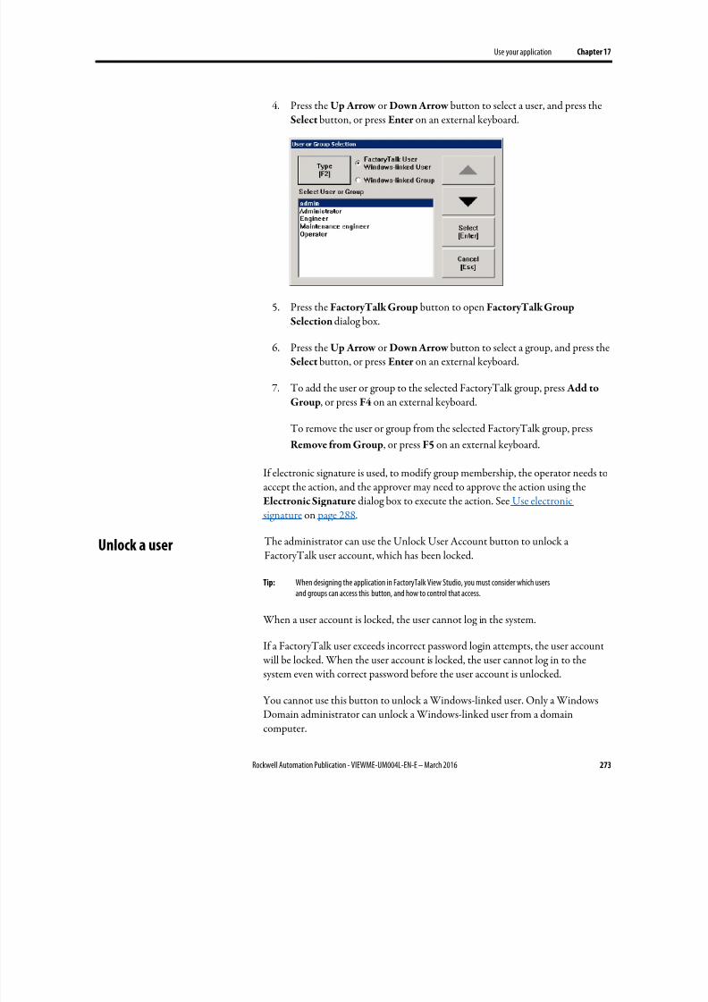
8/17/2019 FactoryTalk® View Machine Edition User's Guide
http://slidepdf.com/reader/full/factorytalk-view-machine-edition-users-guide 273/587
Use your application Chapter 17
Rockwell Automation Publication - VIEWME-UM004L-EN-E – March 2016 273
4. Press the Up Arrow or Down Arrow button to select a user, and press theSelect button, or press Enter on an external keyboard.
5.
Press the FactoryTalk Group button to open FactoryTalk GroupSelection dialog box.
6. Press the Up Arrow or Down Arrow button to select a group, and press theSelect button, or press Enter on an external keyboard.
7. To add the user or group to the selected FactoryTalk group, press Add to
Group, or press F4 on an external keyboard.
To remove the user or group from the selected FactoryTalk group, press
Remove from Group, or press F5 on an external keyboard.
If electronic signature is used, to modify group membership, the operator needs toaccept the action, and the approver may need to approve the action using theElectronic Signature dialog box to execute the action. See Use electronicsignature on page 288.
The administrator can use the Unlock User Account button to unlock aFactoryTalk user account, which has been locked.
Tip: When designing the application in FactoryTalk View Studio, you must consider which usersand groups can access this button, and how to control that access.
When a user account is locked, the user cannot log in the system.
If a FactoryTalk user exceeds incorrect password login attempts, the user account will be locked. When the user account is locked, the user cannot log in to thesystem even with correct password before the user account is unlocked.
You cannot use this button to unlock a Windows-linked user. Only a WindowsDomain administrator can unlock a Windows-linked user from a domaincomputer.
Unlock a user
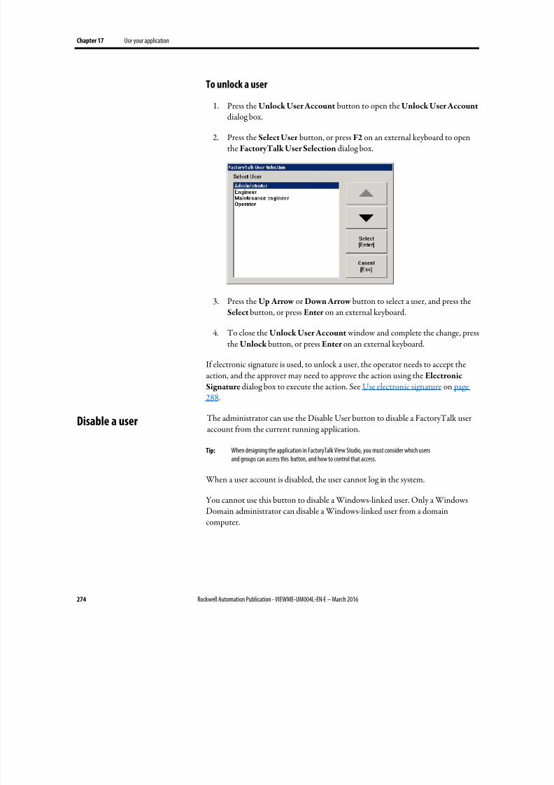
8/17/2019 FactoryTalk® View Machine Edition User's Guide
http://slidepdf.com/reader/full/factorytalk-view-machine-edition-users-guide 274/587
Chapter 17 Use your application
274 Rockwell Automation Publication - VIEWME-UM004L-EN-E – March 2016
To unlock a user
1. Press the Unlock User Account button to open the Unlock User Account
dialog box.
2. Press the Select User button, or press F2 on an external keyboard to openthe FactoryTalk User Selection dialog box.
3. Press the Up Arrow or Down Arrow button to select a user, and press theSelect button, or press Enter on an external keyboard.
4. To close the Unlock User Account window and complete the change, pressthe Unlock button, or press Enter on an external keyboard.
If electronic signature is used, to unlock a user, the operator needs to accept theaction, and the approver may need to approve the action using the Electronic
Signature dialog box to execute the action. See Use electronic signature on page288.
The administrator can use the Disable User button to disable a FactoryTalk useraccount from the current running application.
Tip: When designing the application in FactoryTalk View Studio, you must consider which usersand groups can access this button, and how to control that access.
When a user account is disabled, the user cannot log in the system.
You cannot use this button to disable a Windows-linked user. Only a WindowsDomain administrator can disable a Windows-linked user from a domaincomputer.
Disable a user
8/17/2019 FactoryTalk® View Machine Edition User's Guide
http://slidepdf.com/reader/full/factorytalk-view-machine-edition-users-guide 275/587
Use your application Chapter 17
Rockwell Automation Publication - VIEWME-UM004L-EN-E – March 2016 275
To disable a user
1. Press the Disable User button to open the Disable User Account dialog
box.
2. Press the Select User button, or press F2 on an external keyboard to openthe FactoryTalk User Selection dialog box.
3. Press the Up Arrow or Down Arrow button to select a user, and press theSelect button, or press Enter on an external keyboard.
4. To close the Disable User Account window and complete the change, press the Disable button, or press Enter on an external keyboard.
If electronic signature is used, to disable a user, the operator needs to accept the
action, and the approver may need to approve the action using the ElectronicSignature dialog box to execute the action. See Use electronic signature on page288.
The administrator can use the Enable User button to enable a disabledFactoryTalk user account from the current running application.
Tip: When designing the application in FactoryTalk View Studio, you must consider which usersand groups can access this button, and how to control that access.
When a disabled user is enabled, the user can log in the system again.
You cannot use this button to enable a Windows-linked user. Only a WindowsDomain administrator can enable a Windows-linked user from a domaincomputer.
To enable a user
1. Press the Enable User button to open the Enable User Account dialogbox.
2. Press the Select User button, or press F2 on an external keyboard to open
the FactoryTalk User Selection dialog box.
3. Press the Up Arrow or Down Arrow button to select a user, and press theSelect button, or press Enter on an external keyboard.
4. To close the Enable User Account window and complete the change, pressthe Enable button, or press Enter on an external keyboard.
If electronic signature is used, to enable a user, the operator needs to accept theaction, and the approver may need to approve the action using the Electronic
Enable a user
8/17/2019 FactoryTalk® View Machine Edition User's Guide
http://slidepdf.com/reader/full/factorytalk-view-machine-edition-users-guide 276/587
Chapter 17 Use your application
276 Rockwell Automation Publication - VIEWME-UM004L-EN-E – March 2016
Signature dialog box to execute the action. See Use electronic signature on page288.
The administrator can use the Change User Properties button to modify a
FactoryTalk user’s properties in the current running application.
Tip: When designing the application in FactoryTalk View Studio, you must consider which usersand groups can access this button, and how to control that access.
To modify a user’s properties
1. Press the Change User Properties button to open the Change UserProperties dialog box.
2.
Press the Select User button, or press F2 on an external keyboard to openthe FactoryTalk User Selection dialog box.
3. Press the Up Arrow or Down Arrow button to select a user, and press theSelect button, or press Enter on an external keyboard.
The FactoryTalk User Selection dialog box only shows the users already
configured in FactoryTalk Directory and packed in the application.
4. Press the following buttons to adjust the advanced settings:
• User must change password at next logon
• User cannot change password
• Password never expires
• Account is disabled
5.
Press Change to save the changes.
If electronic signature is used, to modify a user's properties, the operator needs toaccept the action, and the approver may need to approve the action using the
Electronic Signature dialog box to execute the action. See Use electronicsignature on page 288.
The operator can enter or ramp numeric values at runtime using the NumericInput Enable button or the numeric input cursor point.
When the operator presses the button or activates the cursor point, the numeric pop-up keypad or scratchpad opens. If you set up the button or cursor point toramp, pressing the object gives it focus, but does not open a pop-up window.
Change User Properties
Enter numeric values
8/17/2019 FactoryTalk® View Machine Edition User's Guide
http://slidepdf.com/reader/full/factorytalk-view-machine-edition-users-guide 277/587
Use your application Chapter 17
Rockwell Automation Publication - VIEWME-UM004L-EN-E – March 2016 277
To use the numeric pop-up scratchpad, a keyboard must be attached to theruntime computer, or the terminal must be a keypad terminal.
For information about setting up the Numeric Input Enable button and numeric
input cursor point, see Help.
You can also use a Ramp button to ramp numeric values. For details, see Help forthe button.
Activate the cursor point
When the numeric input cursor point has focus, the operator can activate thecursor point by pressing any of these keys on the keyboard or keypad:
•
Numbers from 0 to 9
• The minus sign ( - ) or decimal point ( . )
• The Enter key, or an enter button
• The Backspace key, or a backspace button
When the operator activates the numeric input cursor point, the numeric pop-upkeypad or scratchpad opens.
Ramp numeric valuesIf you set up the Numeric Input Enable button or numeric input cursor point toramp values, the operator presses the object to give it focus. When the object hasfocus, the operator can press a move up or move down button, or the Up Arrow orDown Arrow key on a keyboard or keypad, to ramp the value at the Valueconnection.
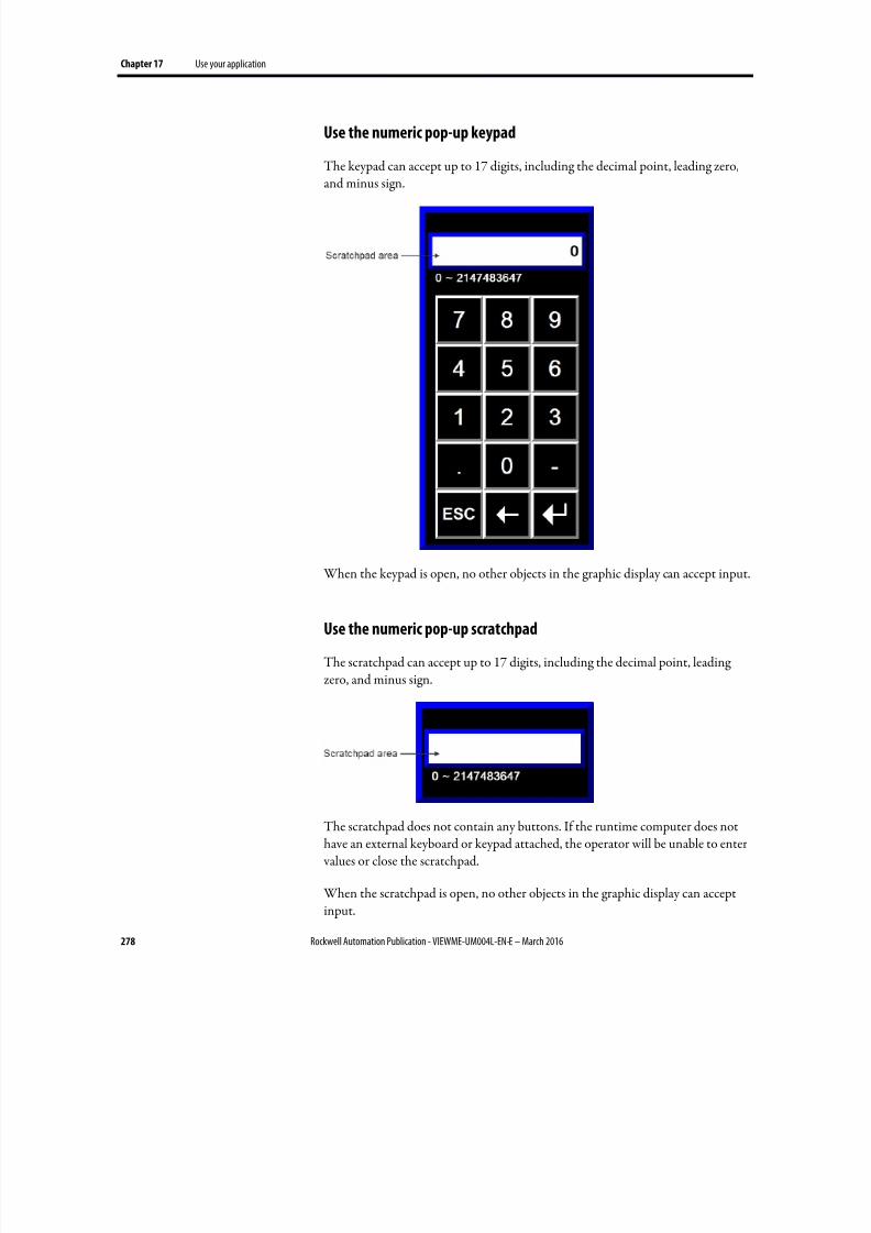
8/17/2019 FactoryTalk® View Machine Edition User's Guide
http://slidepdf.com/reader/full/factorytalk-view-machine-edition-users-guide 278/587
Chapter 17 Use your application
278 Rockwell Automation Publication - VIEWME-UM004L-EN-E – March 2016
Use the numeric pop-up keypad
The keypad can accept up to 17 digits, including the decimal point, leading zero,
and minus sign.
When the keypad is open, no other objects in the graphic display can accept input.
Use the numeric pop-up scratchpad
The scratchpad can accept up to 17 digits, including the decimal point, leadingzero, and minus sign.
The scratchpad does not contain any buttons. If the runtime computer does nothave an external keyboard or keypad attached, the operator will be unable to enter values or close the scratchpad.
When the scratchpad is open, no other objects in the graphic display can acceptinput.
8/17/2019 FactoryTalk® View Machine Edition User's Guide
http://slidepdf.com/reader/full/factorytalk-view-machine-edition-users-guide 279/587
Use your application Chapter 17
Rockwell Automation Publication - VIEWME-UM004L-EN-E – March 2016 279
Use buttons and keys with the numeric pop-up windows
You can use the following buttons and their keyboard or keypad equivalents with
the numeric pop-up keypad. For the pop-up scratchpad, you can use the keys onan external keyboard or keypad only.
Use this button or key To do this
Decimal (.) Type a decimal point.
This button is visible only if the decimal point type for the Numeric Input Enablebutton or numeric input cursor point is Implicit.
Minus (-) Toggle the value between positive and negative.
ESC Close the pop-up window without writing the value to the object’s Value
connection.
Backspace Delete the right-most digit in the scratchpad. If no digits are left, the minus sign,if any, is removed.
Enter Close the pop-up window and write the value to the object’s Value connection.
If the Optional Expression connection is assigned to the button or cursor point,FactoryTalk View calculates the value of the expression and writes the result tothe Value connection. For details, see Use write expressions on page 450.
If Enter key handshaking is set up for the button or cursor point, the object’sEnter connection is set to 1 and the handshaking timer begins timing. Forinformation about using Enter key handshaking, see Methods of Enter keyhandshaking on page 412.
Delete Clear the scratchpad.
There is no Delete button in the pop-up keypad, but you can use the Delete keyon an external keyboard or keypad.
How values are ramped
If the button or cursor point is being used to ramp a value at the Valueconnection:
• When the tag assigned to the Value connection is an integer tag, but theramp value is a floating point value, the ramp value is added to (or
subtracted from) the Value connection value, and then the result isrounded and written to the Value connection.
For information about how values are rounded, see How values are rounded
on page 100.
• If the operator presses and holds down the move up or move down button,or the Up Arrow or Down Arrow key on the keyboard or keypad, thebutton or key goes into auto repeat mode. The ramp value is added to (orsubtracted from) the last value sent to the Value connection.
8/17/2019 FactoryTalk® View Machine Edition User's Guide
http://slidepdf.com/reader/full/factorytalk-view-machine-edition-users-guide 280/587
Chapter 17 Use your application
280 Rockwell Automation Publication - VIEWME-UM004L-EN-E – March 2016
For more information about auto repeat mode, see To set up auto repeat for
a button, use one of these methods on page 411.
• If ramping the button or cursor point would cause the value at the Value
connection to exceed the maximum value, or be less than the minimum value, a message is written to the Diagnostics List and the value at the Value connection is not changed.
How values are calculated
When the pop-up keypad or scratchpad has focus and the operator presses theEnter button, the value that is sent to the Value connection depends on how thebutton or cursor point is set up.
•
The value the operator enters is compared to the minimum and maximumrange for the object. If the value is within the range, the value is written tothe Value connection.
If the Optional Expression connection is assigned, and the original value is
within the range but the expression result is a value outside the range, the
value is still written to the Value connection.
• If the decimal point type is Fixed Position, with a "Digits after decimal" value that is greater than 0, the decimal point is stripped from the valuebefore comparing it to the minimum and maximum range.
For example, if the entered value is 9.25, the stripped value is 925.
If the stripped value is within the range, the stripped value is sent to the
Value connection (or substituted for the ? in the Optional Expression).
• If the decimal point type is Implicit, and the tag assigned to the Value
connection uses an integer data type, floating-point values are rounded.
If the Optional Expression connection is assigned, the floating-point value
is substituted for the ? in the expression, and the expression result is
rounded.
For information about how values are rounded, see How values are rounded on page 100.
Problems with the numeric pop-up windows
Problems with the numeric pop-up keypad and scratchpad occur under thesecircumstances:

8/17/2019 FactoryTalk® View Machine Edition User's Guide
http://slidepdf.com/reader/full/factorytalk-view-machine-edition-users-guide 281/587
Use your application Chapter 17
Rockwell Automation Publication - VIEWME-UM004L-EN-E – March 2016 281
• If the graphic display changes remotely before the user has pressed the Enterbutton, the pop-up window closes without writing out a value.
• If the screen resolution is smaller than 124 pixels wide by 240 pixels high,
the pop-up keypad cannot open.
• If the screen resolution is smaller than 124 pixels wide by 68 pixels high, the pop-up scratchpad cannot open.
• If the value is too large for the data type of the tag assigned to the Value
connection, the pop-up window remains open and the value is not writtento the connection. The scratchpad area changes to red to alert the operatorof the error.
• If the value is outside the minimum and maximum range specified for theobject, the pop-up window remains open and the value is not written to theconnection. The scratchpad area changes to red to alert the operator of theerror.
• If Enter key handshaking is still in effect, the pop-up window closes butthe value is not written to the connection.
The operator can enter string values at runtime using the String Input Enable button.
When the operator presses the button, the string pop-up keyboard or scratchpadopens, depending on how you set up the button. To use the scratchpad, a keyboardmust be attached to the runtime computer.
For information about setting up the String Input Enable button, see Help.
Enter string values
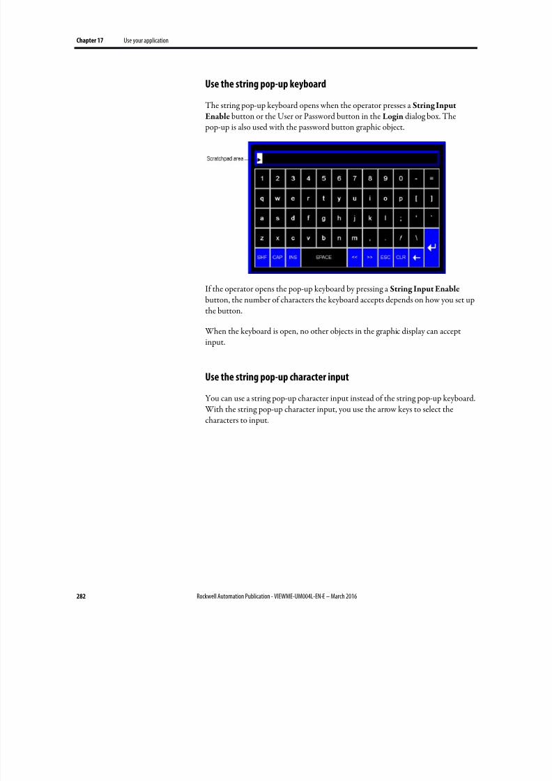
8/17/2019 FactoryTalk® View Machine Edition User's Guide
http://slidepdf.com/reader/full/factorytalk-view-machine-edition-users-guide 282/587
Chapter 17 Use your application
282 Rockwell Automation Publication - VIEWME-UM004L-EN-E – March 2016
Use the string pop-up keyboard
The string pop-up keyboard opens when the operator presses a String Input
Enable button or the User or Password button in the Login dialog box. The pop-up is also used with the password button graphic object.
If the operator opens the pop-up keyboard by pressing a String Input Enable button, the number of characters the keyboard accepts depends on how you set upthe button.
When the keyboard is open, no other objects in the graphic display can acceptinput.
Use the string pop-up character input
You can use a string pop-up character input instead of the string pop-up keyboard. With the string pop-up character input, you use the arrow keys to select thecharacters to input.
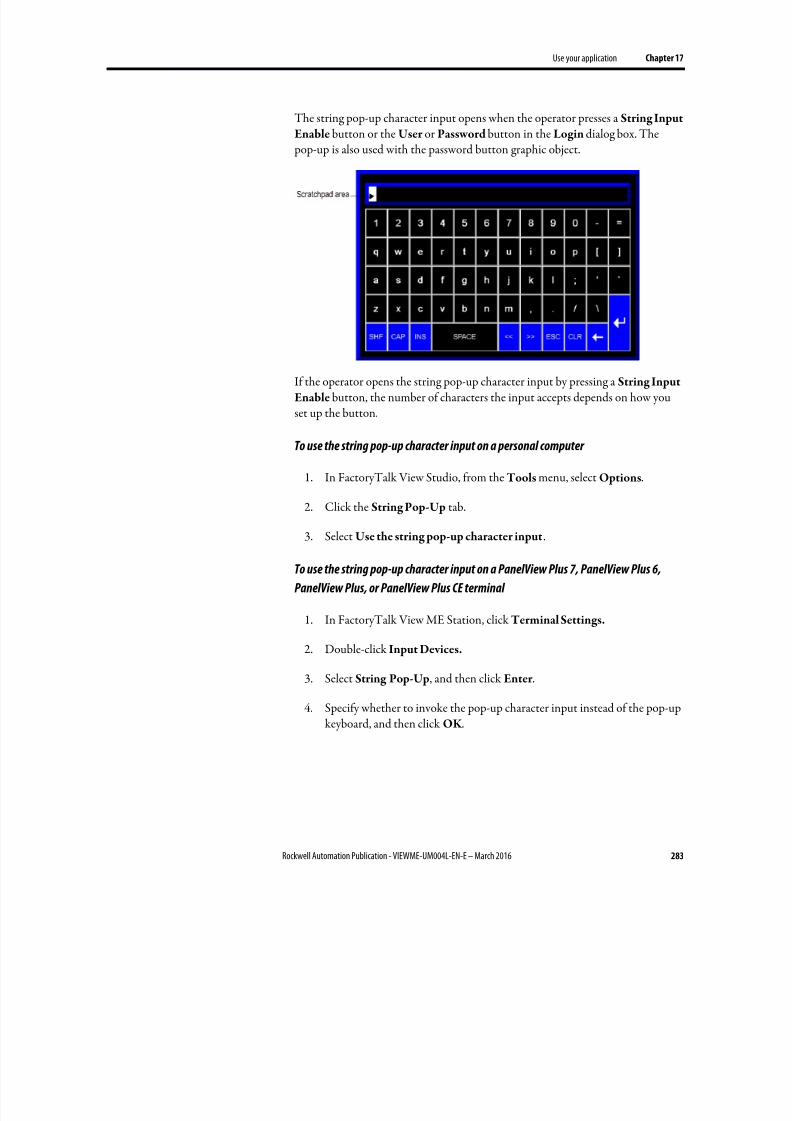
8/17/2019 FactoryTalk® View Machine Edition User's Guide
http://slidepdf.com/reader/full/factorytalk-view-machine-edition-users-guide 283/587
Use your application Chapter 17
Rockwell Automation Publication - VIEWME-UM004L-EN-E – March 2016 283
The string pop-up character input opens when the operator presses a String Input
Enable button or the User or Password button in the Login dialog box. The pop-up is also used with the password button graphic object.
If the operator opens the string pop-up character input by pressing a String Input
Enable button, the number of characters the input accepts depends on how youset up the button.
To use the string pop-up character input on a personal computer
1.
In FactoryTalk View Studio, from the Tools menu, select Options.
2. Click the String Pop-Up tab.
3. Select Use the string pop-up character input.
To use the string pop-up character input on a PanelView Plus 7, PanelView Plus 6,
PanelView Plus, or PanelView Plus CE terminal
1. In FactoryTalk View ME Station, click Terminal Settings.
2. Double-click Input Devices.
3. Select String Pop-Up, and then click Enter .
4.
Specify whether to invoke the pop-up character input instead of the pop-upkeyboard, and then click OK .
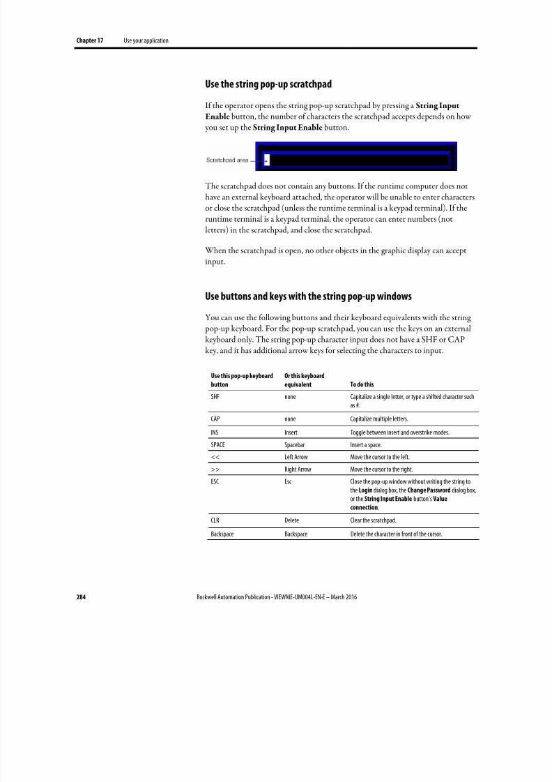
8/17/2019 FactoryTalk® View Machine Edition User's Guide
http://slidepdf.com/reader/full/factorytalk-view-machine-edition-users-guide 284/587
Chapter 17 Use your application
284 Rockwell Automation Publication - VIEWME-UM004L-EN-E – March 2016
Use the string pop-up scratchpad
If the operator opens the string pop-up scratchpad by pressing a String Input
Enable button, the number of characters the scratchpad accepts depends on how you set up the String Input Enable button.
The scratchpad does not contain any buttons. If the runtime computer does nothave an external keyboard attached, the operator will be unable to enter charactersor close the scratchpad (unless the runtime terminal is a keypad terminal). If theruntime terminal is a keypad terminal, the operator can enter numbers (notletters) in the scratchpad, and close the scratchpad.
When the scratchpad is open, no other objects in the graphic display can acceptinput.
Use buttons and keys with the string pop-up windows
You can use the following buttons and their keyboard equivalents with the string pop-up keyboard. For the pop-up scratchpad, you can use the keys on an externalkeyboard only. The string pop-up character input does not have a SHF or CAPkey, and it has additional arrow keys for selecting the characters to input.
Use this pop-up keyboard
button
Or this keyboard
equivalent To do this
SHF none Capitalize a single letter, or type a shifted character suchas #.
CAP none Capitalize multiple letters.
INS Insert Toggle between insert and overstrike modes.
SPACE Spacebar Insert a space.
<< Left Arrow Move the cursor to the left.
>> Right Arrow Move the cursor to the right.
ESC Esc Close the pop-up window without writing the string tothe Login dialog box, the Change Password dialog box,or the String Input Enable button’s Value
connection.
CLR Delete Clear the scratchpad.
Backspace Backspace Delete the character in front of the cursor.
8/17/2019 FactoryTalk® View Machine Edition User's Guide
http://slidepdf.com/reader/full/factorytalk-view-machine-edition-users-guide 285/587
Use your application Chapter 17
Rockwell Automation Publication - VIEWME-UM004L-EN-E – March 2016 285
Use this pop-up keyboard
button
Or this keyboard
equivalent To do this
Enter Enter Close the pop-up window and write the string to theLogin dialog box, the Change Password dialog box, orthe String Input Enable button’s Value connection.
If Enter key handshaking is set up for the String
Input Enable button, the button’s Enter connection isset to 1 and the handshaking timer begins timing. Forinformation about using Enter key handshaking, seeMethods of Enter key handshaking on page 412.
What is written to the Value connection
When the operator presses the Enter button in the pop-up keyboard orscratchpad, the string that is sent to the Value connection depends on how theString Input Enable button is set up.
• If a fill character is set up for the button, and the operator enters fewer thanthe maximum number of input characters, the fill characters are placed afterthe string the operator enters.
• Spaces have a hex value of 20.
• Zeroes have a hex value of 30.
•
FF characters have a hex value of FF.
• Null characters have a hex value of 0. The null character indicates theend of string input. It does not add to the actual string length.
• If the number of input characters is fewer than the number of characters inthe length of the string tag assigned to the Value connection, the remainingspaces are padded with the null character.
When the string is written to the Value connection, the first character is placed inthe high order byte of the first word at the tag address, the second character is placed in the low order byte of the first word, and so on.
Problems with the string pop-up windows
Problems with the string pop-up keyboard and scratchpad occur under thesecircumstances:
• If the graphic display changes remotely before the user has pressed the Enterbutton, the pop-up window closes without writing out a string.
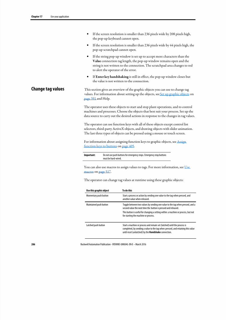
8/17/2019 FactoryTalk® View Machine Edition User's Guide
http://slidepdf.com/reader/full/factorytalk-view-machine-edition-users-guide 286/587
Chapter 17 Use your application
286 Rockwell Automation Publication - VIEWME-UM004L-EN-E – March 2016
• If the screen resolution is smaller than 236 pixels wide by 208 pixels high,the pop-up keyboard cannot open.
• If the screen resolution is smaller than 236 pixels wide by 44 pixels high, the
pop-up scratchpad cannot open.
• If the string pop-up window is set up to accept more characters than the Value connection tag length, the pop-up window remains open and thestring is not written to the connection. The scratchpad area changes to redto alert the operator of the error.
• If Enter key handshaking is still in effect, the pop-up window closes butthe value is not written to the connection.
This section gives an overview of the graphic objects you can use to change tag values. For information about setting up the objects, see Set up graphic objects on
page 391 and Help.
The operator uses these objects to start and stop plant operations, and to controlmachines and processes. Choose the objects that best suit your process. Set up thedata source to carry out the desired actions in response to the changes in tag values.
The operator can use function keys with all of these objects except control listselectors, third-party ActiveX objects, and drawing objects with slider animation.The last three types of objects can be pressed using a mouse or touch screen.
For information about assigning function keys to graphic objects, see Assignfunction keys to buttons on page 405.
Important: Do not use push buttons for emergency stops. Emergency stop buttonsmust be hard-wired.
You can also use macros to assign values to tags. For more information, see Usemacros on page 517.
The operator can change tag values at runtime using these graphic objects:
Use this graphic object To do this
Momentary push button Start a process or action by sending one value to the tag when pressed, and
another value when released.
Maintained push button Toggle between two values by sending one value to the tag when pressed, and asecond value the next time the button is pressed and released.
This button is useful for changing a setting within a machine or process, but notfor starting the machine or process.
Latched push button Start a machine or process and remain set (latched) until the process iscompleted, by sending a value to the tag when pressed, and retaining this valueuntil reset (unlatched) by the Handshake connection.
Change tag values
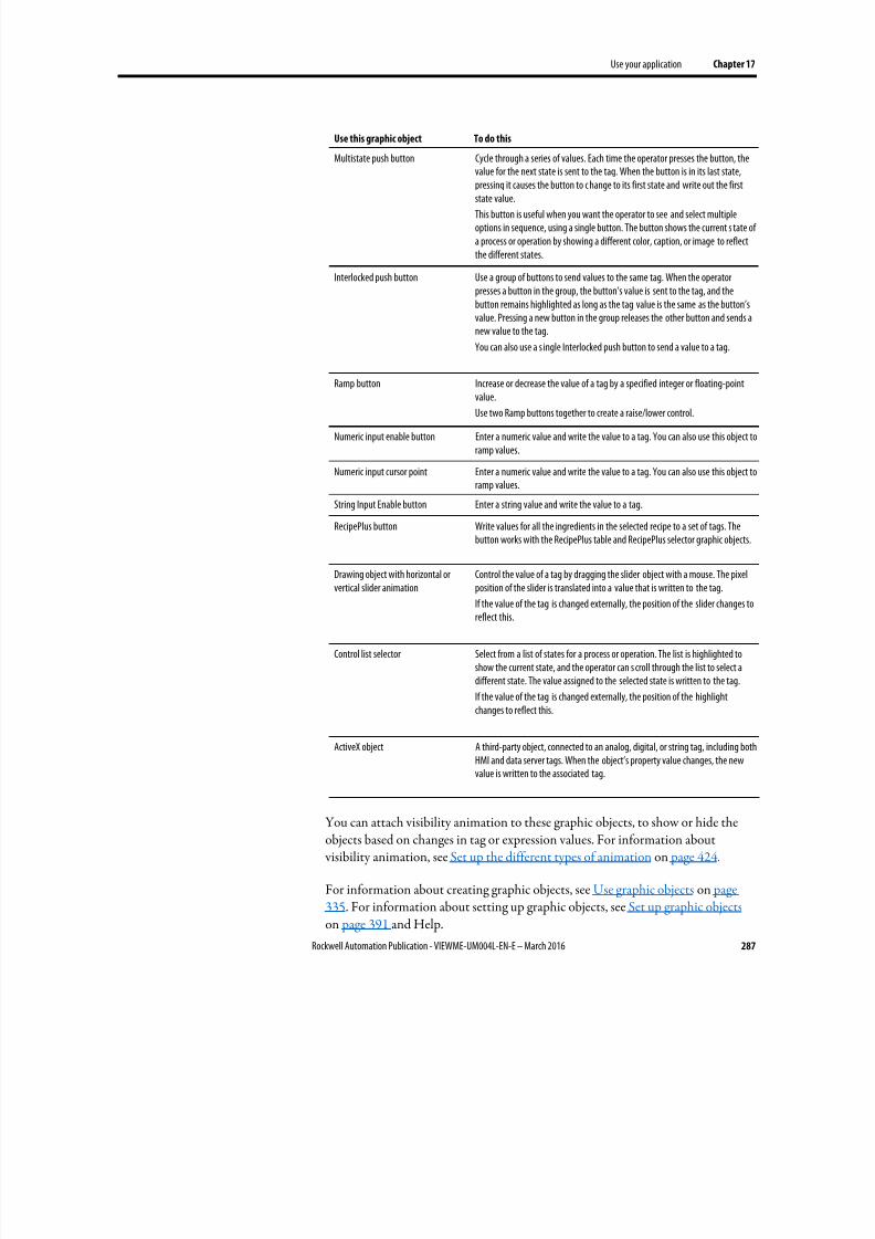
8/17/2019 FactoryTalk® View Machine Edition User's Guide
http://slidepdf.com/reader/full/factorytalk-view-machine-edition-users-guide 287/587
Use your application Chapter 17
Rockwell Automation Publication - VIEWME-UM004L-EN-E – March 2016 287
Use this graphic object To do this
Multistate push button Cycle through a series of values. Each time the operator presses the button, thevalue for the next state is sent to the tag. When the button is in its last state,pressing it causes the button to c hange to its first state and write out the firststate value.
This button is useful when you want the operator to see and select multipleoptions in sequence, using a single button. The button shows the current s tate ofa process or operation by showing a different color, caption, or image to reflectthe different states.
Interlocked push button Use a group of buttons to send values to the same tag. When the operatorpresses a button in the group, the button’s value is sent to the tag, and thebutton remains highlighted as long as the tag value is the same as the button’svalue. Pressing a new button in the group releases the other button and sends anew value to the tag.
You can also use a s ingle Interlocked push button to send a value to a tag.
Ramp button Increase or decrease the value of a tag by a specified integer or floating-pointvalue.
Use two Ramp buttons together to create a raise/lower control.
Numeric input enable button Enter a numeric value and write the value to a tag. You can also use this object toramp values.
Numeric input cursor point Enter a numeric value and write the value to a tag. You can also use this object toramp values.
String Input Enable button Enter a string value and write the value to a tag.
RecipePlus button Write values for all the ingredients in the selected recipe to a set of tags. Thebutton works with the RecipePlus table and RecipePlus selector graphic objects.
Drawing object with horizontal orvertical slider animation
Control the value of a tag by dragging the slider object with a mouse. The pixelposition of the slider is translated into a value that is written to the tag.
If the value of the tag is changed externally, the position of the slider changes toreflect this.
Control list selector Select from a list of states for a process or operation. The list is highlighted toshow the current state, and the operator can s croll through the list to select adifferent state. The value assigned to the selected state is written to the tag.
If the value of the tag is changed externally, the position of the highlightchanges to reflect this.
ActiveX object A third-party object, connected to an analog, digital, or string tag, including bothHMI and data server tags. When the object’s property value changes, the newvalue is written to the associated tag.
You can attach visibility animation to these graphic objects, to show or hide theobjects based on changes in tag or expression values. For information about visibility animation, see Set up the different types of animation on page 424.
For information about creating graphic objects, see Use graphic objects on page335. For information about setting up graphic objects, see Set up graphic objects on page 391 and Help.
8/17/2019 FactoryTalk® View Machine Edition User's Guide
http://slidepdf.com/reader/full/factorytalk-view-machine-edition-users-guide 288/587
Chapter 17 Use your application
288 Rockwell Automation Publication - VIEWME-UM004L-EN-E – March 2016
If electronic signature is used, the operator needs to accept the action, and theapprover may need to approve the action using the Electronic Signature windowto execute the action.
Tip: If electronic signature is used, DEFAULT user cannot propose the action.
The Electronic Signature window has three tabs:
• The Operator tab - Operator accepts the action on this tab.
• The Counter Signatory tab - Approver approves the action on this tab.
• The Review Action tab - This tab shows the action that the operator proposed.
Depending on the design time electronic signature configuration, there are threeoperation modes:
• Comment only - Operator accepts the action by entering comment (ifrequired) and pressing Accept on the Operator tab.
• Single signatory - Operator accepts the action by entering password andcomment (if required), and pressing Accept on the Operator tab.
• Counter signatory - Operator accepts the action by entering password andcomment (if required), and pressing Accept on the Operator tab; andapprover approves the action by entering user name, password, andcomment (if required) on the Counter Signatory tab.
For more information, see "Set up electronic signature properties" in FactoryTalk View Machine Edition Help.
Accept an action in the comment only mode
On the E-Signature tab of the object Properties dialog box, if the Require
Electronic Signature check box is selected, and the Require re-authentication check box is clear, the operation mode is comment only.
Use electronic signature
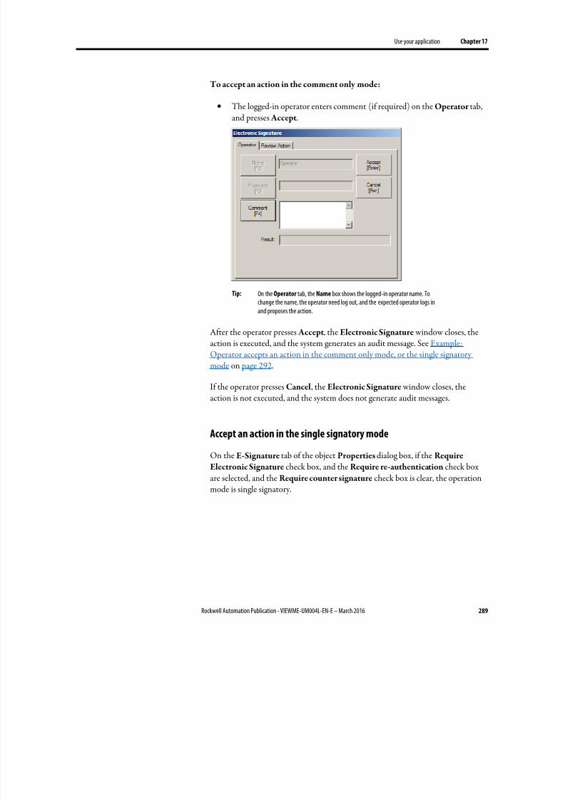
8/17/2019 FactoryTalk® View Machine Edition User's Guide
http://slidepdf.com/reader/full/factorytalk-view-machine-edition-users-guide 289/587
Use your application Chapter 17
Rockwell Automation Publication - VIEWME-UM004L-EN-E – March 2016 289
To accept an action in the comment only mode:
• The logged-in operator enters comment (if required) on the Operator tab,and presses Accept.
Tip: On the Operator tab, the Name box shows the logged-in operator name. Tochange the name, the operator need log out, and the expected operator logs inand proposes the action.
After the operator presses Accept, the Electronic Signature window closes, theaction is executed, and the system generates an audit message. See Example:Operator accepts an action in the comment only mode, or the single signatorymode on page 292.
If the operator presses Cancel, the Electronic Signature window closes, theaction is not executed, and the system does not generate audit messages.
Accept an action in the single signatory mode
On the E-Signature tab of the object Properties dialog box, if the RequireElectronic Signature check box, and the Require re-authentication check boxare selected, and the Require counter signature check box is clear, the operationmode is single signatory.
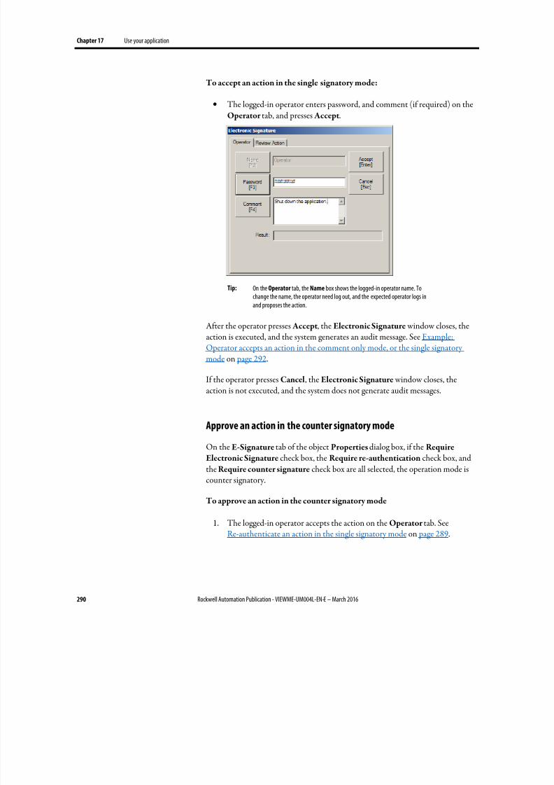
8/17/2019 FactoryTalk® View Machine Edition User's Guide
http://slidepdf.com/reader/full/factorytalk-view-machine-edition-users-guide 290/587
Chapter 17 Use your application
290 Rockwell Automation Publication - VIEWME-UM004L-EN-E – March 2016
To accept an action in the single signatory mode:
• The logged-in operator enters password, and comment (if required) on theOperator tab, and presses Accept.
Tip: On the Operator tab, the Name box shows the logged-in operator name. Tochange the name, the operator need log out, and the expected operator logs inand proposes the action.
After the operator presses Accept, the Electronic Signature window closes, theaction is executed, and the system generates an audit message. See Example:Operator accepts an action in the comment only mode, or the single signatorymode on page 292.
If the operator presses Cancel, the Electronic Signature window closes, theaction is not executed, and the system does not generate audit messages.
Approve an action in the counter signatory mode
On the E-Signature tab of the object Properties dialog box, if the RequireElectronic Signature check box, the Require re-authentication check box, andthe Require counter signature check box are all selected, the operation mode iscounter signatory.
To approve an action in the counter signatory mode
1. The logged-in operator accepts the action on the Operator tab. SeeRe-authenticate an action in the single signatory mode on page 289.
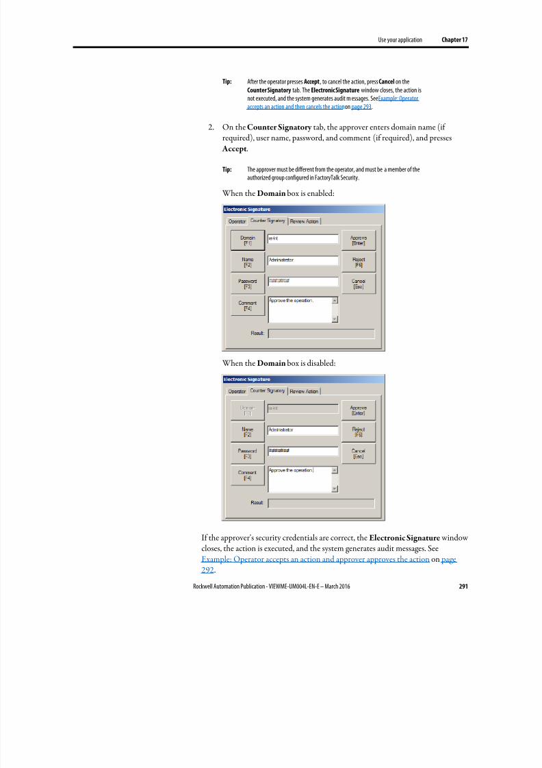
8/17/2019 FactoryTalk® View Machine Edition User's Guide
http://slidepdf.com/reader/full/factorytalk-view-machine-edition-users-guide 291/587
Use your application Chapter 17
Rockwell Automation Publication - VIEWME-UM004L-EN-E – March 2016 291
Tip: After the operator presses Accept, to cancel the action, press Cancel on theCounter Signatory tab. The Electronic Signature window closes, the action isnot executed, and the system generates audit m essages. See Example: Operatoraccepts an action and then cancels the action on page 293.
2. On the Counter Signatory tab, the approver enters domain name (ifrequired), user name, password, and comment (if required), and presses
Accept.
Tip: The approver must be different from the operator, and must be a member of theauthorized group configured in FactoryTalk Security.
When the Domain box is enabled:
When the Domain box is disabled:
If the approver's security credentials are correct, the Electronic Signature windowcloses, the action is executed, and the system generates audit messages. SeeExample: Operator accepts an action and approver approves the action on page292.
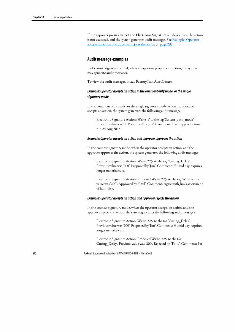
8/17/2019 FactoryTalk® View Machine Edition User's Guide
http://slidepdf.com/reader/full/factorytalk-view-machine-edition-users-guide 292/587
Chapter 17 Use your application
292 Rockwell Automation Publication - VIEWME-UM004L-EN-E – March 2016
If the approver presses Reject, the Electronic Signature window closes, the actionis not executed, and the system generates audit messages. See Example: Operatoraccepts an action and approver rejects the action on page 292.
Audit message examples
If electronic signature is used, when an operator proposes an action, the systemmay generate audit messages.
To view the audit messages, install FactoryTalk AssetCentre.
Example: Operator accepts an action in the comment only mode, or the single
signatory mode
In the comment only mode, or the single signatory mode, when the operatoraccepts an action, the system generates the following audit message:
Electronic Signature Action: Write '1' to the tag 'System_auto_mode'.Previous value was '0'. Performed by 'Jim'. Comment: Starting productionrun 24.Aug.2015.
Example: Operator accepts an action and approver approves the action
In the counter signatory mode, when the operator accepts an action, and the
approver approves the action, the system generates the following audit messages:
Electronic Signature Action: Write '225' to the tag 'Curing_Delay'.Previous value was '200'. Proposed by 'Jim'. Comment: Humid day requireslonger material cure.
Electronic Signature Action: Proposed Write '225' to the tag 'A'. Previous value was '200'. Approved by 'Emil'. Comment: Agree with Jim’s assessmentof humidity.
Example: Operator accepts an action and approver rejects the action
In the counter signatory mode, when the operator accepts an action, and theapprover rejects the action, the system generates the following audit messages:
Electronic Signature Action: Write '225' to the tag 'Curing_Delay'.Previous value was '200'. Proposed by 'Jim'. Comment: Humid day requireslonger material cure.
Electronic Signature Action: Proposed Write '225' to the tagCuring_Delay'. Previous value was '200'. Rejected by 'Tony'. Comment: Per
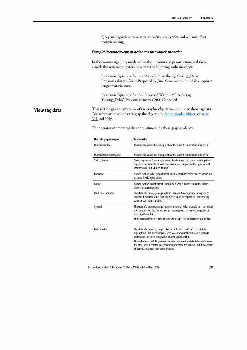
8/17/2019 FactoryTalk® View Machine Edition User's Guide
http://slidepdf.com/reader/full/factorytalk-view-machine-edition-users-guide 293/587
Use your application Chapter 17
Rockwell Automation Publication - VIEWME-UM004L-EN-E – March 2016 293
QA process guidelines, relative humidity is only 55% and will not affectmaterial curing.
Example: Operator accepts an action and then cancels the action
In the counter signatory mode, when the operator accepts an action, and thencancels the action, the system generates the following audit messages:
Electronic Signature Action: Write '225' to the tag 'Curing_Delay'.Previous value was '200'. Proposed by 'Jim'. Comment: Humid day requireslonger material cure.
Electronic Signature Action: Proposed Write '225' to the tag'Curing_Delay'. Previous value was '200'. Cancelled
This section gives an overview of the graphic objects you can use to show tag data.For information about setting up the objects, see Set up graphic objects on page391 and Help.
The operator can view tag data at runtime using these graphic objects:
Use this graphic object To show this
Numeric display Numeric tag values. For example, show the current temperature of an oven.
Numeric input cursor point Numeric tag values. For example, show the current temperature of an oven.
String display String tag values. For example, set up the data source to generate strings that
report on the state of a process or operation, or that provide the operator withinstructions about what to do next.
Bar graph Numeric values in bar graph format. The bar graph increases or decreases in sizeto show the changing value.
Gauge Numeric values in dial format. The gauge’s needle moves around the dial toshow the changing value.
Multistate indicator The state of a process, on a panel that changes its color, image, or caption toindicate the current state. Each state is set up to correspond to a numeric tagvalue or least significant bit.
Symbol The state of a process, using a monochrome image that changes color to indicatethe current state. Each state is set up to correspond to a numeric tag value orleast significant bit.
This object is useful for showing the state of a process or operation at a glance.
List indicator The state of a process, using a list of possible states with the current statehighlighted. Each state is represented by a caption in the list, and is set up tocorrespond to a numeric tag value or least significant bit.
This indicator is useful if you want to view the current state but also want to seethe other possible states. For sequential processes, the list can alert the operatorabout what happens next in the process.
View tag data
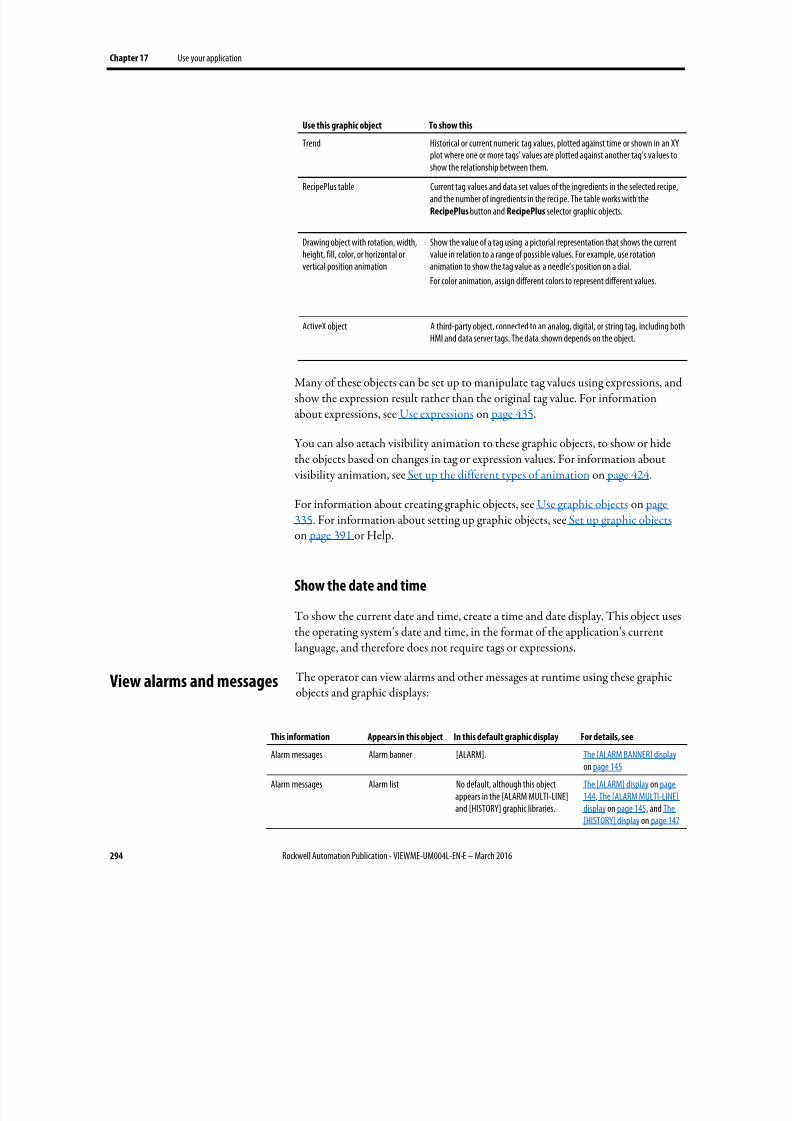
8/17/2019 FactoryTalk® View Machine Edition User's Guide
http://slidepdf.com/reader/full/factorytalk-view-machine-edition-users-guide 294/587
Chapter 17 Use your application
294 Rockwell Automation Publication - VIEWME-UM004L-EN-E – March 2016
Use this graphic object To show this
Trend Historical or current numeric tag values, plotted against time or shown in an XYplot where one or more tags’ values are plotted against another tag’s va lues toshow the relationship between them.
RecipePlus table Current tag values and data set values of the ingredients in the selected recipe,and the number of ingredients in the reci pe. The table works with theRecipePlus button and RecipePlus selector graphic objects.
Drawing object with rotation, width,height, fill, color, or horizontal orvertical position animation
Show the value of a tag using a pictorial representation that shows the currentvalue in relation to a range of possi ble values. For example, use rotationanimation to show the tag value as a needle’s position on a dial.
For color animation, assign different colors to represent different values.
ActiveX object A third-party object, connected to an analog, digital, or string tag, including bothHMI and data server tags. The data shown depends on the object.
Many of these objects can be set up to manipulate tag values using expressions, andshow the expression result rather than the original tag value. For informationabout expressions, see Use expressions on page 435.
You can also attach visibility animation to these graphic objects, to show or hidethe objects based on changes in tag or expression values. For information about visibility animation, see Set up the different types of animation on page 424.
For information about creating graphic objects, see Use graphic objects on page
335. For information about setting up graphic objects, see Set up graphic objects on page 391 or Help.
Show the date and time
To show the current date and time, create a time and date display. This object usesthe operating system’s date and time, in the format of the application’s currentlanguage, and therefore does not require tags or expressions.
The operator can view alarms and other messages at runtime using these graphic
objects and graphic displays:
This information Appears in this object In this default graphic display For details, see
Alarm messages Alarm banner [ALARM]. The [ALARM BANNER] display on page 145
Alarm messages Alarm list No default, although this objectappears in the [ALARM MULTI-LINE]and [HISTORY] graphic libraries.
The [ALARM] display on page144, The [ALARM MULTI-LINE]display on page 145, and The[HISTORY] display on page 147
View alarms and messages
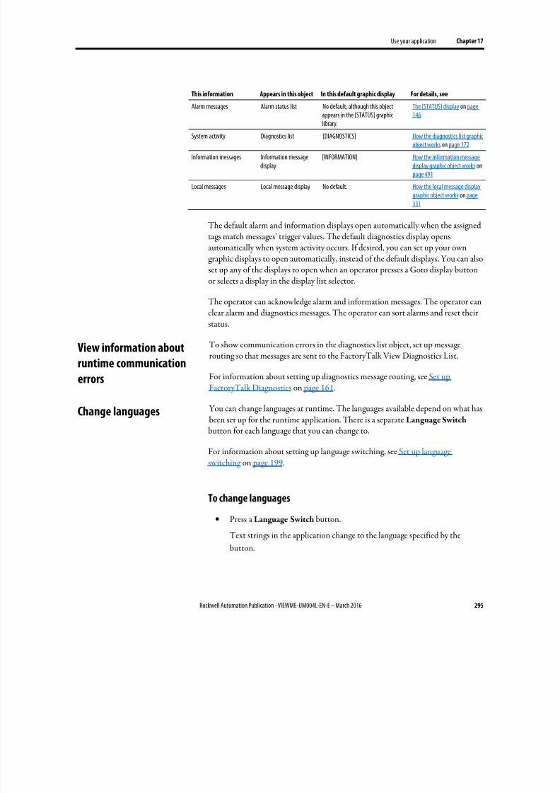
8/17/2019 FactoryTalk® View Machine Edition User's Guide
http://slidepdf.com/reader/full/factorytalk-view-machine-edition-users-guide 295/587
Use your application Chapter 17
Rockwell Automation Publication - VIEWME-UM004L-EN-E – March 2016 295
This information Appears in this object In this default graphic display For details, see
Alarm messages Alarm status list No default, although this objectappears in the [STATUS] graphic
library.
The [STATUS] display on page146
System activity Diagnostics list [DIAGNOSTICS] How the diagnostics list graphicobject works on page 172
Information messages Information messagedisplay
[INFORMATION] How the information messagedisplay graphic object works onpage 491
Local messages Local message display No default. How the local message displaygraphic object works on page331
The default alarm and information displays open automatically when the assignedtags match messages’ trigger values. The default diagnostics display opens
automatically when system activity occurs. If desired, you can set up your owngraphic displays to open automatically, instead of the default displays. You can alsoset up any of the displays to open when an operator presses a Goto display buttonor selects a display in the display list selector.
The operator can acknowledge alarm and information messages. The operator canclear alarm and diagnostics messages. The operator can sort alarms and reset theirstatus.
To show communication errors in the diagnostics list object, set up messagerouting so that messages are sent to the FactoryTalk View Diagnostics List.
For information about setting up diagnostics message routing, see Set upFactoryTalk Diagnostics on page 161.
You can change languages at runtime. The languages available depend on what hasbeen set up for the runtime application. There is a separate Language Switchbutton for each language that you can change to.
For information about setting up language switching, see Set up languageswitching on page 199.
To change languages
• Press a Language Switch button.
Text strings in the application change to the language specified by the
button.
View information about
runtime communicationerrors
Change languages

8/17/2019 FactoryTalk® View Machine Edition User's Guide
http://slidepdf.com/reader/full/factorytalk-view-machine-edition-users-guide 296/587
Chapter 17 Use your application
296 Rockwell Automation Publication - VIEWME-UM004L-EN-E – March 2016
8/17/2019 FactoryTalk® View Machine Edition User's Guide
http://slidepdf.com/reader/full/factorytalk-view-machine-edition-users-guide 297/587
Rockwell Automation Publication - VIEWME-UM004L-EN-E – March 2016 297
Chapter 18
Work with components
This chapter describes:
• Which editors have components
• Work with components
• Print information in components
For information on working with particular editors, see the chapters later in thisguide.
With some editors you enter information in a single window or a tabbed dialogbox. Other editors allow you to create multiple components, such as graphicdisplays or message files. Each component is stored in a separate file, with its ownname.
You can create components in these editors:
• Graphics (components include graphic displays, global object displays, and
graphic libraries, each in their own folder)• Parameters
• Local Messages
• Information Messages
• Data Log Models
• Macros
• RecipePlus
The Explorer window lists the components you create under the icon for theeditor you used to create the component.
You can use the Images editor to copy bitmap images into your application (butnot to create new images). Each image you copy is listed as a component under theeditor.
Editors that have
components
8/17/2019 FactoryTalk® View Machine Edition User's Guide
http://slidepdf.com/reader/full/factorytalk-view-machine-edition-users-guide 298/587
Chapter 18 Work with components
298 Rockwell Automation Publication - VIEWME-UM004L-EN-E – March 2016
To view a list of components for an editor
• Click the + symbol to the left of the editor icon, or double-click the editorname.
This section describes how to perform basic operations that are common to allcomponents.
For information on working with components in particular editors, see thechapters later in this guide.
Create components
To create a new component, do one of the following
• Drag the component icon into the workspace.
• Right-click the editor, and then click New .
• From the File menu, select New , and then click the type of component tocreate.
Open components
To open a component, do one of the following
• Double-click the component.
• Right-click the component and select Open.
• Drag the component from the Explorer window to the workspace.
Save components
The Save tool is available when the active component contains unsavedchanges.
Work with components
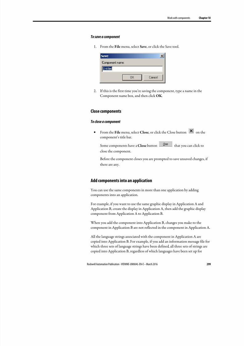
8/17/2019 FactoryTalk® View Machine Edition User's Guide
http://slidepdf.com/reader/full/factorytalk-view-machine-edition-users-guide 299/587
Work with components Chapter 18
Rockwell Automation Publication - VIEWME-UM004L-EN-E – March 2016 299
To save a component
1. From the File menu, select Save, or click the Save tool.
2. If this is the first time you’re saving the component, type a name in theComponent name box, and then click OK .
Close components
To close a component
• From the File menu, select Close, or click the Close button on thecomponent’s title bar.
Some components have a Close button that you can click to
close the component.
Before the component closes you are prompted to save unsaved changes, ifthere are any.
Add components into an application
You can use the same components in more than one application by addingcomponents into an application.
For example, if you want to use the same graphic display in Application A andApplication B, create the display in Application A, then add the graphic display
component from Application A to Application B.
When you add the component into Application B, changes you make to thecomponent in Application B are not reflected in the component in Application A.
All the language strings associated with the component in Application A arecopied into Application B. For example, if you add an information message file for which three sets of language strings have been defined, all three sets of strings arecopied into Application B, regardless of which languages have been set up for
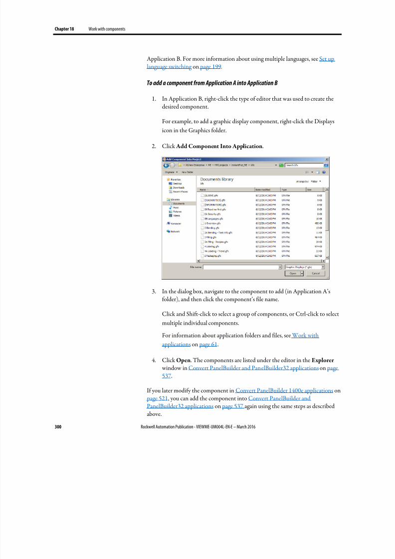
8/17/2019 FactoryTalk® View Machine Edition User's Guide
http://slidepdf.com/reader/full/factorytalk-view-machine-edition-users-guide 300/587
Chapter 18 Work with components
300 Rockwell Automation Publication - VIEWME-UM004L-EN-E – March 2016
Application B. For more information about using multiple languages, see Set uplanguage switching on page 199.
To add a component from Application A into Application B
1. In Application B, right-click the type of editor that was used to create thedesired component.
For example, to add a graphic display component, right-click the Displays
icon in the Graphics folder.
2. Click Add Component Into Application.
3. In the dialog box, navigate to the component to add (in Application A’sfolder), and then click the component’s file name.
Click and Shift-click to select a group of components, or Ctrl-click to select
multiple individual components.
For information about application folders and files, see Work with
applications on page 61.
4. Click Open. The components are listed under the editor in the Explorer window in Convert PanelBuilder and PanelBuilder32 applications on page537.
If you later modify the component in Convert PanelBuilder 1400e applications on page 521, you can add the component into Convert PanelBuilder andPanelBuilder32 applications on page 537 again using the same steps as describedabove.
8/17/2019 FactoryTalk® View Machine Edition User's Guide
http://slidepdf.com/reader/full/factorytalk-view-machine-edition-users-guide 301/587
Work with components Chapter 18
Rockwell Automation Publication - VIEWME-UM004L-EN-E – March 2016 301
Use Add Component Into Application with graphic displays, graphic libraries, and
global object displays
The Add Component Into Application menu command is also useful for:
• adding graphic displays to your application’s Libraries folder
• using libraries as graphic displays in your application
• moving libraries into the Displays folder so you can export their strings fortranslation
• creating global object displays
For information about graphic libraries, see Use graphic libraries on page 316.
For information about global object displays, see Create global object displays andbase objects on page 470.
Delete components
Deleting a component deletes it from the Explorer window and from the harddisk.
To delete a component
•
Right-click the component, and then select Delete.
Remove components
You can remove a component from the Explorer window but leave it on the harddisk, in case you want to use the component in another application.
To remove a component
Right-click the component, and then select Remove.
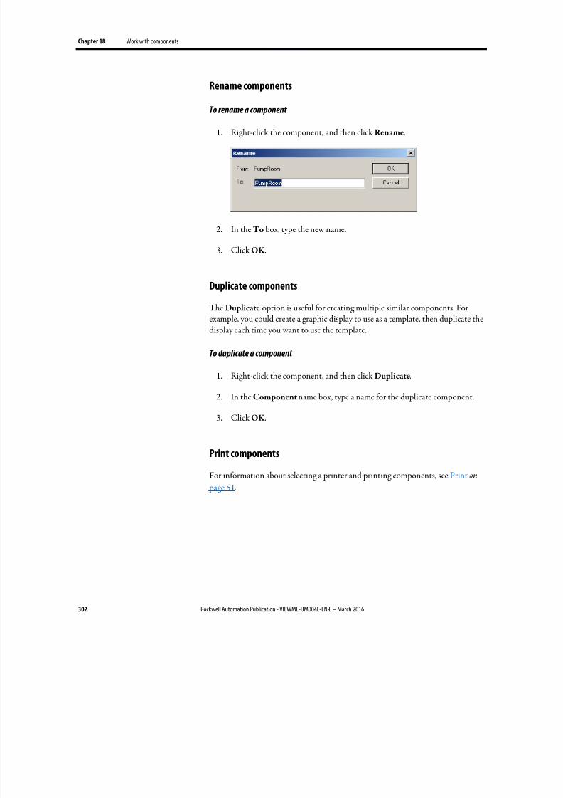
8/17/2019 FactoryTalk® View Machine Edition User's Guide
http://slidepdf.com/reader/full/factorytalk-view-machine-edition-users-guide 302/587
Chapter 18 Work with components
302 Rockwell Automation Publication - VIEWME-UM004L-EN-E – March 2016
Rename components
To rename a component
1. Right-click the component, and then click Rename.
2. In the To box, type the new name.
3.
Click OK .
Duplicate components
The Duplicate option is useful for creating multiple similar components. Forexample, you could create a graphic display to use as a template, then duplicate thedisplay each time you want to use the template.
To duplicate a component
1.
Right-click the component, and then click Duplicate.
2. In the Component name box, type a name for the duplicate component.
3. Click OK .
Print components
For information about selecting a printer and printing components, see Print on
page 51.
8/17/2019 FactoryTalk® View Machine Edition User's Guide
http://slidepdf.com/reader/full/factorytalk-view-machine-edition-users-guide 303/587
Rockwell Automation Publication - VIEWME-UM004L-EN-E – March 2016 303
Chapter 19
Use graphic displays
This chapter describes the Graphics, Images, and Local Messages editors in theGraphics folder and outlines how to:
• Use the Graphics editor
• Set up graphic displays
• Create a background for your displays
• Use graphic libraries
• Import graphic images
• Create local messages in your displays
• Print graphic displays at runtime
Before creating graphic displays, specify project settings. Project settings determineimportant aspects of your graphic display such as size and position. For moreinformation, see About project settings on page 73.
For information about global object displays and the Parameters editor, see Use parameters and global objects on page 461.
A graphic display represents the operator’s view of plant activity. The display canshow system or process data and provide operators with a way to write values to anexternal data source. The data source can be memory or a device such as a programmable controller or an OPC server.
Operators can print the display at runtime to create a visual record of tag values,object states, or current messages.
The elements that make up a graphic display are called graphic objects. You cancreate objects in the Graphics editor, or copy them from a global object display,from a graphic library, or from another application.
For information about creating and copying graphic objects, see Use graphicobjects on page 335.
You can use up to 1,000 tags per graphic display. This limit includes the tagscontained in embedded variables.
About graphic displays and
graphic objects
8/17/2019 FactoryTalk® View Machine Edition User's Guide
http://slidepdf.com/reader/full/factorytalk-view-machine-edition-users-guide 304/587
Chapter 19 Use graphic displays
304 Rockwell Automation Publication - VIEWME-UM004L-EN-E – March 2016
PanelView Plus 7 Standard applications and Compact Machine Editionapplications (applications running on PanelView Plus 6 Compact or PanelViewPlus Compact terminals) have a limited number of displays.
Before you begin, plan your displays. Think about what information the operatorneeds to see, and the best way to provide the information. For example:
• Does the operator need to know the exact speed of a conveyor belt, or just whether the belt is moving, jammed, or stopped?
• Do different users need to have access to different types of information?
• Do you need to limit access to certain types of information?
Also consider the runtime environment and how the operator will use theapplication:
• Does the runtime computer have a touch screen, mouse, keyboard, or somecombination of these?
• How will the operator navigate through the displays of the application?
• Will the application be available in multiple languages?
Review the chapters on planning, security, and navigation before you begincreating displays. Browse through the sample applications for design ideas. Mapout a display hierarchy. Then create a graphic display to use as a template.
The time you spend planning your displays will make your application easy to useand will save you time in the long run.
For information about See
Plan your displays and creating a template Plan applications on page 53
Set up application security to control access to displays Set up security on page 175
Set up display navigation and creating a display hierarchy Set up display navigation on page 215
Set up how objects are used at runtime Set up graphic objects on page 391
The Graphics editor opens when you create or open a graphic display, globalobject display, or graphic library. Each display is stored in the Displays folder. Youcan open and work on multiple graphic displays at the same time.
Before you begin
Use the Graphics editor
8/17/2019 FactoryTalk® View Machine Edition User's Guide
http://slidepdf.com/reader/full/factorytalk-view-machine-edition-users-guide 305/587
Use graphic displays Chapter 19
Rockwell Automation Publication - VIEWME-UM004L-EN-E – March 2016 305
Create and open graphic displays
To create a graphic display
1. In the Graphics folder, do one of the following:
• Right-click Displays and then click New .
• Click the New Display tool .
• Drag and drop the Displays icon into the workspace.
2. From the Edit menu, select Display Settings to open the Display Settings dialog box and specify settings for the display.
For more information, see Set up graphic displays on page 312.
3. Create the objects you want to put on the display.
For information about creating graphic objects, see Use graphic objects on
page 335.
4. From the File menu, select Save, or click the Save tool .
5. In the Component name box, type a name for the display, and then click
OK .
The display is added to the list in the Displays folder.
The display is created as a Replace display by default, but you can change it
to an On Top display in the Display Settings dialog box. For more
information about display types, see About display types on page 313.
To open a graphic display
• In the Graphics folder, open the Displays folder and then double-click the
display name, or right-click the display name and then click Open.You can also drag and drop the display from the Explorer window to an
empty area in the FactoryTalk View Studio workspace.
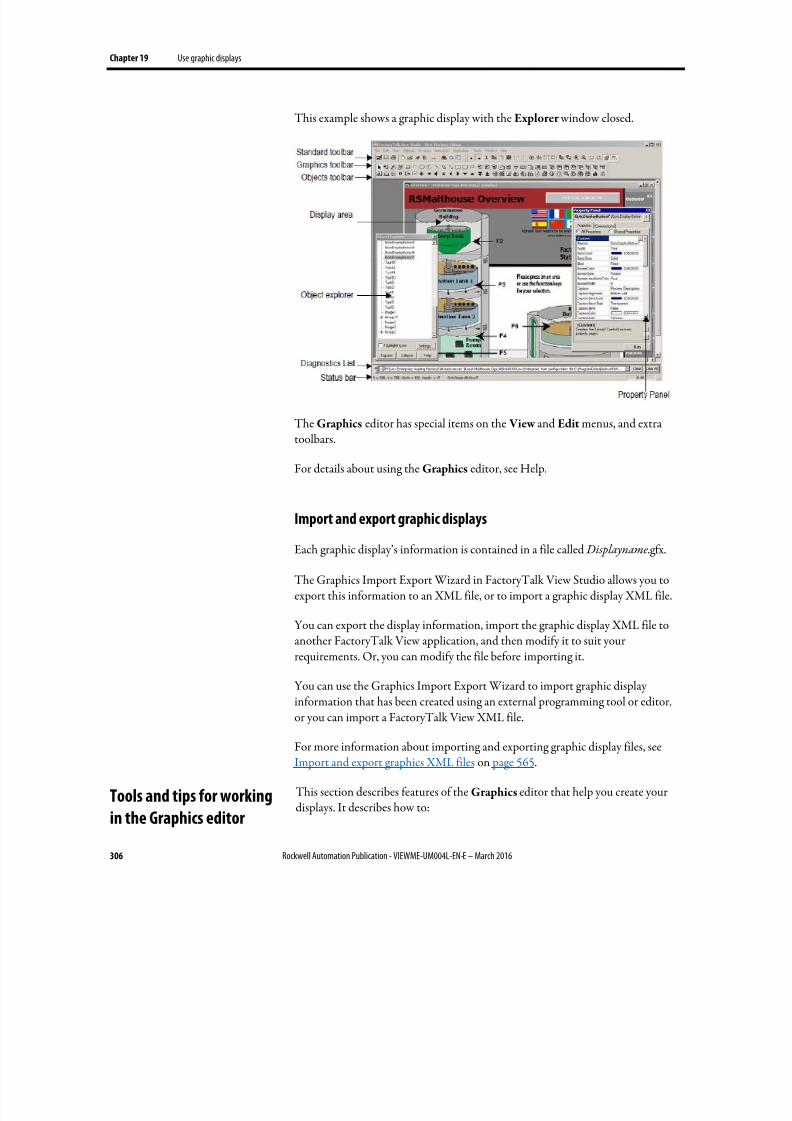
8/17/2019 FactoryTalk® View Machine Edition User's Guide
http://slidepdf.com/reader/full/factorytalk-view-machine-edition-users-guide 306/587
Chapter 19 Use graphic displays
306 Rockwell Automation Publication - VIEWME-UM004L-EN-E – March 2016
This example shows a graphic display with the Explorer window closed.
The Graphics editor has special items on the View and Edit menus, and extratoolbars.
For details about using the Graphics editor, see Help.
Import and export graphic displays
Each graphic display’s information is contained in a file called Displayname.gfx.
The Graphics Import Export Wizard in FactoryTalk View Studio allows you toexport this information to an XML file, or to import a graphic display XML file.
You can export the display information, import the graphic display XML file toanother FactoryTalk View application, and then modify it to suit yourrequirements. Or, you can modify the file before importing it.
You can use the Graphics Import Export Wizard to import graphic displayinformation that has been created using an external programming tool or editor,or you can import a FactoryTalk View XML file.
For more information about importing and exporting graphic display files, seeImport and export graphics XML files on page 565.
This section describes features of the Graphics editor that help you create yourdisplays. It describes how to:
Tools and tips for working
in the Graphics editor
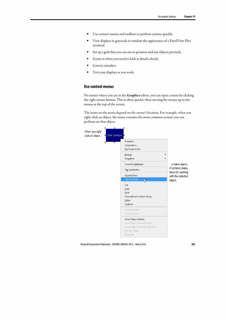
8/17/2019 FactoryTalk® View Machine Edition User's Guide
http://slidepdf.com/reader/full/factorytalk-view-machine-edition-users-guide 307/587
Use graphic displays Chapter 19
Rockwell Automation Publication - VIEWME-UM004L-EN-E – March 2016 307
• Use context menus and toolbars to perform actions quickly.
• View displays in grayscale to emulate the appearance of a PanelView Plusterminal.
•
Set up a grid that you can use to position and size objects precisely.
• Zoom in when you need to look at details closely.
• Correct mistakes.
• Test your displays as you work.
Use context menus
No matter where you are in the Graphics editor, you can open a menu by clicking
the right mouse button. This is often quicker than moving the mouse up to themenus at the top of the screen.
The items on the menu depend on the cursor’s location. For example, when youright-click an object, the menu contains the most common actions you can perform on that object.
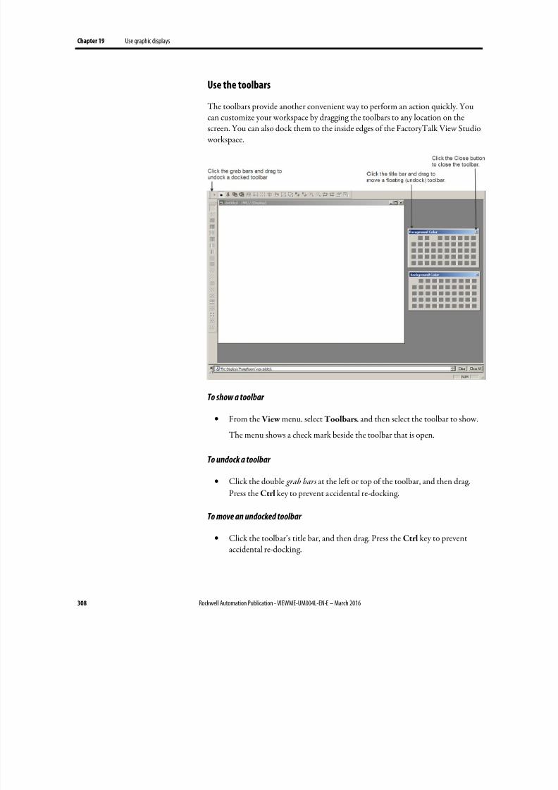
8/17/2019 FactoryTalk® View Machine Edition User's Guide
http://slidepdf.com/reader/full/factorytalk-view-machine-edition-users-guide 308/587
Chapter 19 Use graphic displays
308 Rockwell Automation Publication - VIEWME-UM004L-EN-E – March 2016
Use the toolbars
The toolbars provide another convenient way to perform an action quickly. You
can customize your workspace by dragging the toolbars to any location on thescreen. You can also dock them to the inside edges of the FactoryTalk View Studio workspace.
To show a toolbar
• From the View menu, select Toolbars, and then select the toolbar to show.
The menu shows a check mark beside the toolbar that is open.
To undock a toolbar
• Click the double grab bars at the left or top of the toolbar, and then drag.
Press the Ctrl key to prevent accidental re-docking.
To move an undocked toolbar
• Click the toolbar’s title bar, and then drag. Press the Ctrl key to preventaccidental re-docking.
8/17/2019 FactoryTalk® View Machine Edition User's Guide
http://slidepdf.com/reader/full/factorytalk-view-machine-edition-users-guide 309/587
Use graphic displays Chapter 19
Rockwell Automation Publication - VIEWME-UM004L-EN-E – March 2016 309
To dock a toolbar
• Click the toolbar’s title bar, and then drag to any edge of the workspace.
To close a toolbar
• From the View menu, select Toolbars, and then select the name of thetoolbar to close, or click the toolbar’s Close button.
Show displays in grayscale
You can set displays to appear in grayscale, especially for developing applicationsthat will run on the PanelView Plus grayscale terminals. When Show Displays in
Grayscale is checked (on the View menu), all open displays will change from fullcolor to grayscale. When Show Displays in Grayscale is cleared, all open displays will appear in color.
Show Displays in Grayscale does not work in Test Application mode.
Third party ActiveX objects will not appear in grayscale if Show Displays inGrayscale is checked.
Use the grid
To size and position objects precisely, use the grid. You can change the gridsettings at any time during the drawing process.
The grid can be active or passive. When the grid is active, all the objects you drawor position are pulled to the closest grid point. This makes it easy to align and sizeobjects. When the grid is passive, it is visible but does not affect the position of your objects.
Make the grid passive to position an element between the grid lines. Make the gridactive, and the next object you draw or place is automatically aligned with the grid.Making the grid active does not affect the placement of existing objects.
The grid is visible during application development only. It is not visible atruntime.
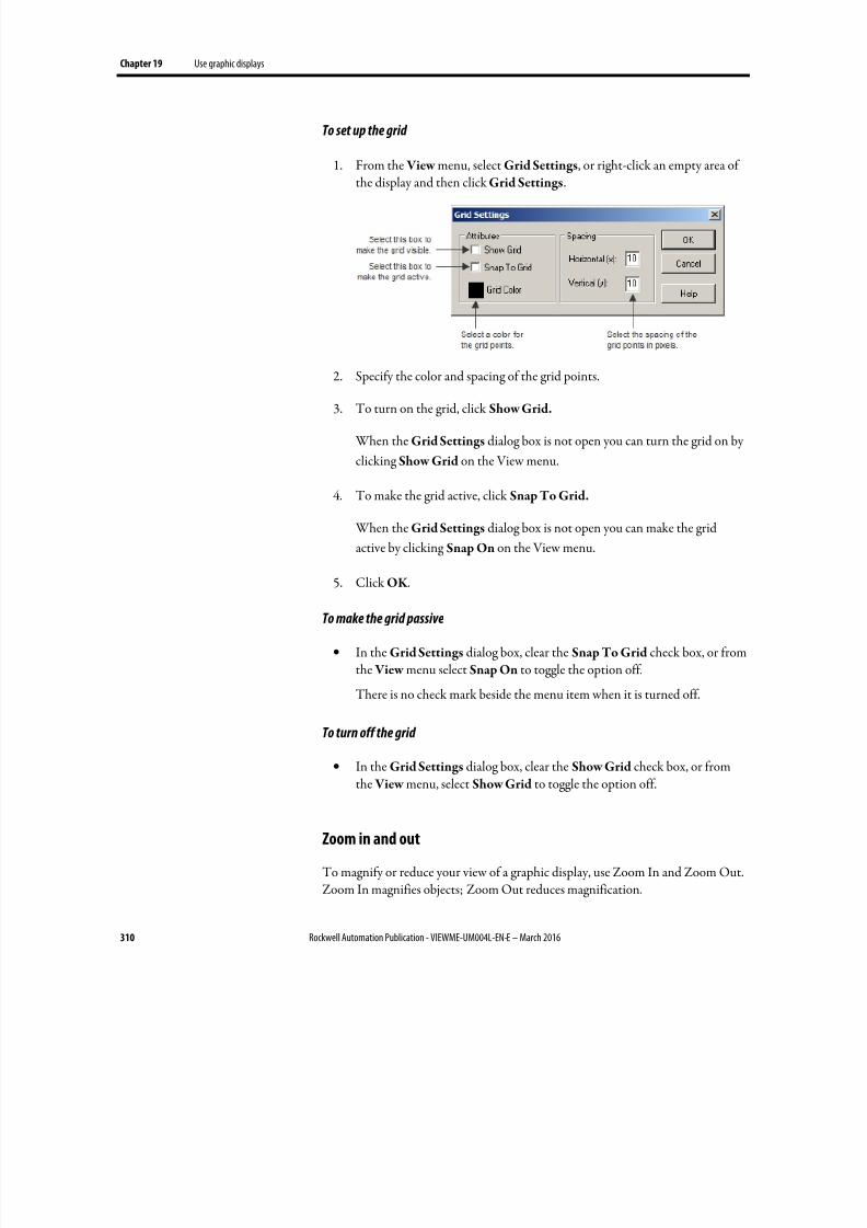
8/17/2019 FactoryTalk® View Machine Edition User's Guide
http://slidepdf.com/reader/full/factorytalk-view-machine-edition-users-guide 310/587
Chapter 19 Use graphic displays
310 Rockwell Automation Publication - VIEWME-UM004L-EN-E – March 2016
To set up the grid
1. From the View menu, select Grid Settings, or right-click an empty area of
the display and then click Grid Settings
.
2.
Specify the color and spacing of the grid points.
3. To turn on the grid, click Show Grid.
When the Grid Settings dialog box is not open you can turn the grid on by
clicking Show Grid on the View menu.
4. To make the grid active, click Snap To Grid.
When the Grid Settings dialog box is not open you can make the grid
active by clicking Snap On on the View menu.
5. Click OK .
To make the grid passive
• In the Grid Settings dialog box, clear the Snap To Grid check box, or fromthe View menu select Snap On to toggle the option off.
There is no check mark beside the menu item when it is turned off.
To turn off the grid
•
In the Grid Settings dialog box, clear the Show Grid check box, or fromthe View menu, select Show Grid to toggle the option off.
Zoom in and out
To magnify or reduce your view of a graphic display, use Zoom In and Zoom Out.Zoom In magnifies objects; Zoom Out reduces magnification.
8/17/2019 FactoryTalk® View Machine Edition User's Guide
http://slidepdf.com/reader/full/factorytalk-view-machine-edition-users-guide 311/587
Use graphic displays Chapter 19
Rockwell Automation Publication - VIEWME-UM004L-EN-E – March 2016 311
To zoom in on objects
1. Select the objects you want to zoom in on.
2. From the View menu, select Zoom In, or click the Zoom In tool .
To zoom out
• From the View menu, select Zoom Out, or click the Zoom Out tool .
Correct mistakes
If you change your mind about something you did, you can undo the action. If you
change your mind again, you can redo the action.
You can undo and redo all the operations you performed since you last saved thedisplay, one operation at a time.
The operations you perform between opening and closing a dialog box are treatedas a single operation. Operations you perform in the Property Panel are treated asseparate operations.
To undo an operation
•
From the Edit menu, click Undo, or click the Undo tool .
To redo an operation
• From the Edit menu, select Redo, or click the Redo tool .
Test your displays as you work
To test the objects in your displays as you work, use the Test Display tool to switchto test mode. When you are finished testing, switch back to edit mode to continue
editing.
8/17/2019 FactoryTalk® View Machine Edition User's Guide
http://slidepdf.com/reader/full/factorytalk-view-machine-edition-users-guide 312/587
Chapter 19 Use graphic displays
312 Rockwell Automation Publication - VIEWME-UM004L-EN-E – March 2016
Tip: Test mode is not the same as running the display. It does not change the appearance orposition of the display as set up in the Display Settings dialog box. Alarm andinformation messages are not shown, although if communications are set up, tag valuesare read and written. Display navigation, data logging, and macros do not work in thismode. If you want to test these features, test the application as descri bed on Test yourapplication on page 223.
If you set up local messages and graphic objects to use multiple languages, themessages and objects are shown in the current application language during testmode.
Use the Diagnostics List when in test mode
The Diagnostics List shows messages about system activities when you test yourgraphic displays. You can specify the types of messages to show in the Diagnostics
List, move the list, resize it, and clear the messages in it.
For information about using the Diagnostics List, see The Diagnostics List on page 43.
For information about specifying the types of messages to show in theDiagnostics List, see Show diagnostics messages during application development on page 165.
To use test mode
• From the View menu, select Test Display , or click the Test Display tool
.
To return to edit mode
• From the View menu, select Edit Display, or click the Edit Display tool
.
To set up a graphic display, specify its type, background color, and runtimebehavior in the Display Settings dialog box. You can specify and edit the displaysettings at any time while you work on your display.
Set up graphic displays
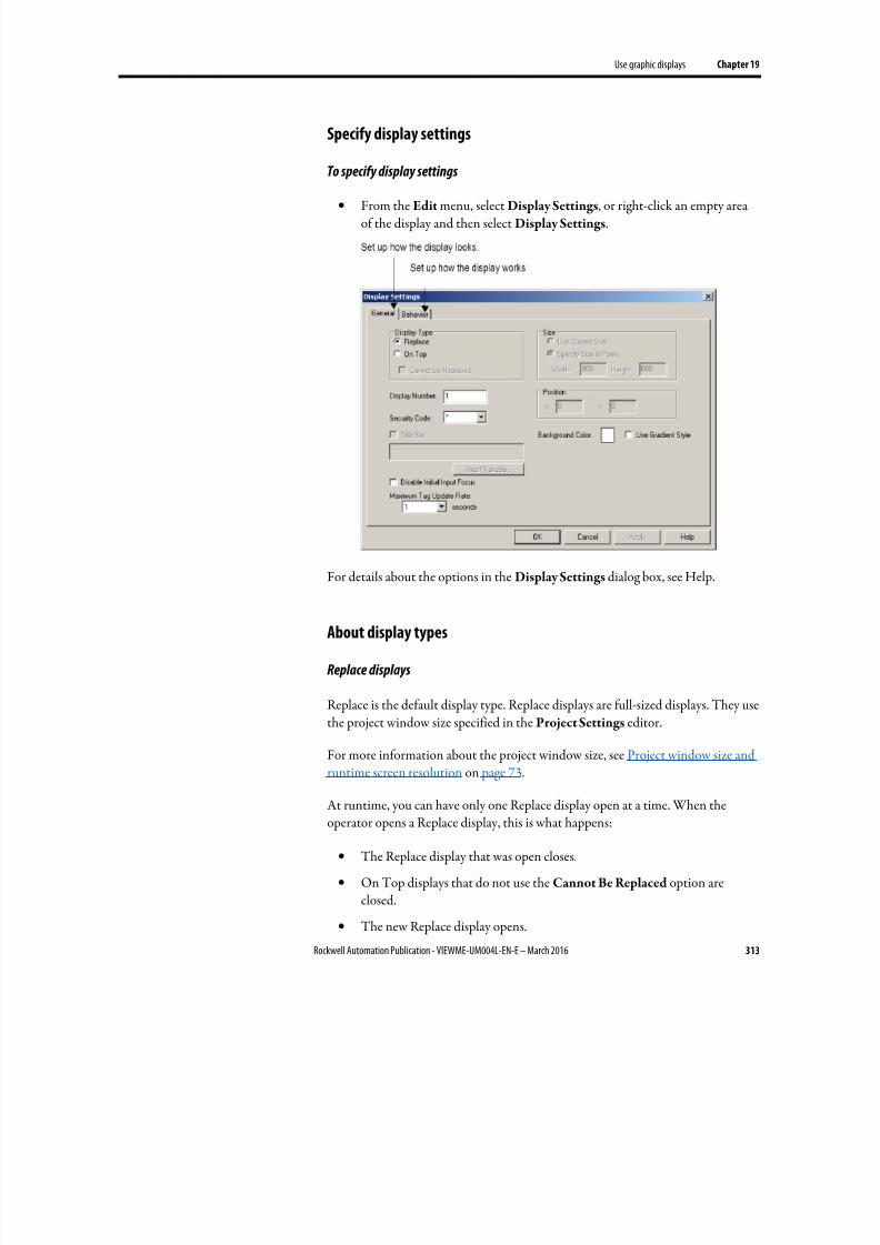
8/17/2019 FactoryTalk® View Machine Edition User's Guide
http://slidepdf.com/reader/full/factorytalk-view-machine-edition-users-guide 313/587
Use graphic displays Chapter 19
Rockwell Automation Publication - VIEWME-UM004L-EN-E – March 2016 313
Specify display settings
To specify display settings
• From the Edit menu, select Display Settings, or right-click an empty areaof the display and then select Display Settings.
For details about the options in the Display Settings dialog box, see Help.
About display types
Replace displays
Replace is the default display type. Replace displays are full-sized displays. They usethe project window size specified in the Project Settings editor.
For more information about the project window size, see Project window size and
runtime screen resolution on page 73.
At runtime, you can have only one Replace display open at a time. When theoperator opens a Replace display, this is what happens:
• The Replace display that was open closes.
• On Top displays that do not use the Cannot Be Replaced option areclosed.
• The new Replace display opens.
8/17/2019 FactoryTalk® View Machine Edition User's Guide
http://slidepdf.com/reader/full/factorytalk-view-machine-edition-users-guide 314/587
Chapter 19 Use graphic displays
314 Rockwell Automation Publication - VIEWME-UM004L-EN-E – March 2016
• On Top displays that use the Cannot Be Replaced option remain open, ontop of the new Replace display.
If the operator attempts to open a Replace display that is already open (forexample, using a Goto display button to which the same display is assigned), thedisplay does not close and FactoryTalk View sends an error message toFactoryTalk Diagnostics.
On Top displays
Use the On Top option to create pop-up displays that open on top of the currentReplace display. Usually, On Top displays are smaller than Replace displays, so theoperator does not lose track of display navigation.
You can open multiple On Top displays. If more than one On Top display is
open, the display that has focus, or had the most recent focus, appears on top.
When an On Top display closes, the display that had the most recent focusappears on top.
Use the Cannot Be Replaced option if you want the On Top display to remainopen when a new Replace display is opened.
On Top displays do not have a Close button in the title bar. Be sure to create aclose button graphic object in On Top displays so the operator can close them.
The operator cannot move an On Top display by dragging its title bar. Theruntime position of the display is fixed (according to the position settings definedfor the display).
You can specify unique titles for On Top displays. You can use embedded variablesin the title, and the title text can switch languages at runtime.
Resize displays
The project window size is used for all Replace displays. If you change the project
window size after you have designed any graphic displays, you have the option ofscaling graphic displays.
If you choose to scale graphic displays, all Replace and On Top displays are resizedand the objects in them are scaled to fit the new size. You can also specify whetherto scale the font size and border size of the graphic objects, and the size of graphicimages in the Images folder.
8/17/2019 FactoryTalk® View Machine Edition User's Guide
http://slidepdf.com/reader/full/factorytalk-view-machine-edition-users-guide 315/587
Use graphic displays Chapter 19
Rockwell Automation Publication - VIEWME-UM004L-EN-E – March 2016 315
If you choose not to scale displays when you change the project window size,Replace displays are resized, but any objects on the displays remain the same sizeand in the same position as before. On Top displays are not resized.
For information about specifying the project window size, see Project window sizeand runtime screen resolution on page 73.
Change the display area while working
You can change the display area of a display while you’re working on it by draggingthe border of the display area. For example, you might want to make the displayarea smaller so you can see parts of two displays in order to drag and drop objectsbetween them.
Changing the display area in this manner does not change the display size for
Replace displays. For On Top displays that are sized with the Use Current Size option, dragging the border does resize the display.
Another way to arrange multiple displays while working on them is to use theoptions on the Windows menu. For example, Tile Horizontal arranges all theopen displays with as much of the top part of each display showing as possible.
You can create a background for your graphic display by converting graphicobjects to wallpaper. When objects are converted to wallpaper, they are lockedinto position and become an unchanging background for the other objects on thedisplay.
Convert objects that do not need to be animated or updated with tag values cansignificantly improve the runtime performance of a graphic display.
Objects that have been converted to wallpaper cannot be selected or edited until you unlock the wallpaper. Also, animations attached to the wallpaper objects arenot in effect. However, animations are restored when you unlock the wallpaper.
Similarly, any tags or expressions assigned to an object become inactive when theobject is converted to wallpaper. Connections are restored if you unlock the wallpaper.
To manage a number of objects easily, group the objects, and then convert thegroup to wallpaper.
To convert objects to wallpaper
1.
Select the objects to convert.
Create a background for
your display
8/17/2019 FactoryTalk® View Machine Edition User's Guide
http://slidepdf.com/reader/full/factorytalk-view-machine-edition-users-guide 316/587
Chapter 19 Use graphic displays
316 Rockwell Automation Publication - VIEWME-UM004L-EN-E – March 2016
2. For information about selecting objects, see Select and deselect objects on page 357.
3. From the Edit menu, select Wallpaper , and then click Convert to
Wallpaper.
4. For a single object, you can right-click it and then select Convert to
Wallpaper .
To unlock the wallpaper
• From the Edit menu, select Wallpaper , and then click Unlock All
Wallpaper .
All objects in the graphic display are converted back to their original state.
There are two graphic libraries that are available, Symbol Factory and GraphicsLibrary
FactoryTalk View Studio Graphics Library comes with a set of libraries, containedin the Libraries folder. As with a public library, the graphics libraries can provide you with source materials and reference information.
Each graphic library consists of a graphic display, with the file extension .gfx. Thelibrary displays contain graphic objects that you might find useful in your ownapplication. Many of the objects are preconfigured with animation. For example,
see the Conveyor parts library.
You can:
• Look at the objects and displays to get ideas for your own application.
• Drag and drop (or copy and paste) objects from the libraries into your owndisplays.
For information about copying objects from a library into your graphic
display, see Copy objects on page 376.
•
Use the objects as they are or change them to suit your needs.• Create your own libraries of objects.
• Create libraries of displays that are translated into multiple languages.
• Use libraries as displays in your application.
The Symbol Factory is a library of over 5,000 graphics for industrial automation,including pumps, pipes, valves, tanks, mixers, motors, ducts, electrical symbols,flow meters, material handling, sensors, PLCs, transmitters, and ISA symbols.
Use graphic libraries
Work with Symbol Factory
8/17/2019 FactoryTalk® View Machine Edition User's Guide
http://slidepdf.com/reader/full/factorytalk-view-machine-edition-users-guide 317/587
Use graphic displays Chapter 19
Rockwell Automation Publication - VIEWME-UM004L-EN-E – March 2016 317
To open Symbol Factory
Symbol Factory opens into a new window when launched, there are four ways to
open Symbol Factory:
• From the Explorer window, double-click Symbol Factory
• From the Objects menu is available, select Symbol Factory
• When the Objects toolbar is available, click
• Clicking the Launch Symbol Factory button in the Image Browser
To select a graphic:
1.
Browse the Categories frame, clicking a category to see the symbols in theright frame.
2. Click the graphic to select it for the Graphic Display.
If the graphic is to be used in this original state, it can be dragged and dropped intothe Graphic Display.
Tip: When View Studio is unlicensed and in Grace Period mode, the Symbol Factory library willbe in demo mode and restricted in the number and type of graphics available for use. Onlya licensed View Studio can enable a fully licensed Symbol Factory library.
Manipulate the graphic:
With the graphic selected, it can be modified using Symbol Factory
1. Select Options on the menu.
2. Select Symbol Options from the drop down menu.
3.
The Symbol Options dialog box allows the graphic to be modified inseveral ways. The orientation can be changed, it can be rotated, the fill colorcan be changed and applied to the graphic in different modes.
4. The Preview frame will show the changes made to the graphic.
5. When finished modifying, the graphic can be dragged and dropped from thePreview frame to the Graphic Display, or copied and pasted into theGraphic Display.
8/17/2019 FactoryTalk® View Machine Edition User's Guide
http://slidepdf.com/reader/full/factorytalk-view-machine-edition-users-guide 318/587
Chapter 19 Use graphic displays
318 Rockwell Automation Publication - VIEWME-UM004L-EN-E – March 2016
Symbol Factory has its own Help file which explains operations within SymbolFactory and its functions.
For more information, click Help in the Symbol Factory
To open a graphic library
1. In the Explorer window, open the Graphics folder, and then open theLibraries folder.
2. Double-click the library name, or right-click it and then select Open.
Create graphic libraries
You can create a graphic library in the Libraries folder, or create a graphic displayin the Displays folder and then add the display to the Libraries folder.
To create a graphic library
1. In the Graphics folder, right-click Libraries and then click New .
2. Create the objects you want to put in the library.
For information about creating graphic objects, see Use graphic objects on
page 335.
3. From the File menu select Save, or click the Save tool .
4. In the Component name box, type a name for the library, and then clickOK .
The library is added to the list in the Libraries folder.
You can also create a graphic display and then use Add Component IntoApplication to add the display to the Libraries folder.
To add a graphic display to the library
1. Create the graphic display.
2. In the Explorer window, in the Graphics folder, right-click the Libraries
icon.
3. Click Add Component Into Application.
8/17/2019 FactoryTalk® View Machine Edition User's Guide
http://slidepdf.com/reader/full/factorytalk-view-machine-edition-users-guide 319/587
Use graphic displays Chapter 19
Rockwell Automation Publication - VIEWME-UM004L-EN-E – March 2016 319
4. In the dialog box, navigate to the Gfx folder and select the .gfx file for thedisplay to use.
The Gfx folder is in \Users\Public\Public Documents\RSView
Enterprise\ME\HMI projects\ Application Name
where Application Name is the name of your application.
5. Click Open. The display is copied into the Libraries folder.
Use libraries as displays in your application
The graphic libraries are available on the development computer, but do notappear at runtime. To use a library as a graphic display at runtime, you must addthe library into your application’s folder of graphic displays.
If the library does not contain strings for languages supported by the currentapplication, the undefined strings are shown with question marks (?).
To use a library as a display in your application
1. In the Explorer window, in the Graphics folder, right-click the Displaysicon.
2. Click Add Component Into Application.
3. In the dialog box, navigate to the Libraries folder and select the .gfx file forthe library to use. The Libraries folder is \Users\Public\Public
Documents\RSView Enterprise\ME
4. Click Open.
The library is copied to the Displays folder.
Use libraries to store displays with multiple languages
The maximum number of languages an application can use is 40 duringdevelopment, and 20 at runtime. Since the libraries are stored outside of the HMI project folder and are available to all applications, they do not have this limit.However, since they are not stored in the HMI project folder, you cannot exportthe strings in library displays for translation. Instead, export a graphic display fortranslation, import the translated strings, then add the display into the library.
When you use a library display in your application, make sure you add to yourapplication the languages that you plan to use from the library.
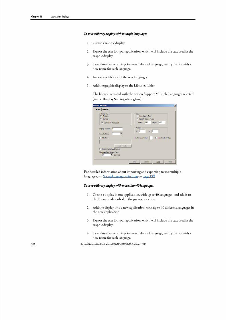
8/17/2019 FactoryTalk® View Machine Edition User's Guide
http://slidepdf.com/reader/full/factorytalk-view-machine-edition-users-guide 320/587
Chapter 19 Use graphic displays
320 Rockwell Automation Publication - VIEWME-UM004L-EN-E – March 2016
To save a library display with multiple languages
1. Create a graphic display.
2.
Export the text for your application, which will include the text used in thegraphic display.
3. Translate the text strings into each desired language, saving the file with anew name for each language.
4. Import the files for all the new languages.
5. Add the graphic display to the Libraries folder.
The library is created with the option Support Multiple Languages selected
(in the Display Settings dialog box).
For detailed information about importing and exporting to use multiplelanguages, see Set up language switching on page 199.
To save a library display with more than 40 languages
1. Create a display in one application, with up to 40 languages, and add it to
the library, as described in the previous section.
2. Add the display into a new application, with up to 40 different languages inthe new application.
3.
Export the text for your application, which will include the text used in thegraphic display.
4. Translate the text strings into each desired language, saving the file with anew name for each language.
8/17/2019 FactoryTalk® View Machine Edition User's Guide
http://slidepdf.com/reader/full/factorytalk-view-machine-edition-users-guide 321/587
Use graphic displays Chapter 19
Rockwell Automation Publication - VIEWME-UM004L-EN-E – March 2016 321
5. Import the files for the new languages.
6. Add the graphic display (with the same name as the display in step 1) to theLibraries folder.
The new languages are added to the library. Make sure the display contains
the same objects as the original display. Otherwise the new display will
overwrite the previous display, and all the original language strings will be
undefined.
What is shown
When you open a library that supports multiple languages, the strings are shownusing the current application language, if available. If the library does not contain
the current language, the strings are shown as single question marks. Similarly, ifthe library contains the language but not all the strings are defined for thelanguage, undefined strings are shown as single question marks.
For more information about using multiple languages with graphic libraries, seeSet up language switching on page 199.
Location of library components
The Libraries folder is in \Users\Public\Public Documents\RSView
Enterprise\ME
You can specify a different directory in which to store library components. If youspecify a different directory, FactoryTalk View saves graphic libraries that you addor create in the new directory. Similarly, when you open a library componentFactoryTalk View looks for the component in the specified directory.
If you specify a different directory but want to use the libraries that come withFactoryTalk View, use My Computer or Windows Explorer to copy the librarycomponent files into the directory you have specified, or else change the path backto the default path when you want to open a FactoryTalk View librarycomponent.
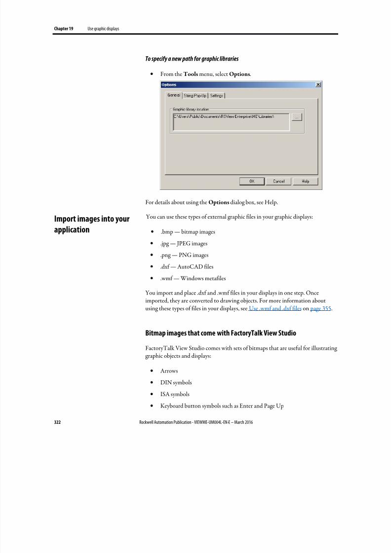
8/17/2019 FactoryTalk® View Machine Edition User's Guide
http://slidepdf.com/reader/full/factorytalk-view-machine-edition-users-guide 322/587
Chapter 19 Use graphic displays
322 Rockwell Automation Publication - VIEWME-UM004L-EN-E – March 2016
To specify a new path for graphic libraries
• From the Tools menu, select Options.
For details about using the Options dialog box, see Help.
You can use these types of external graphic files in your graphic displays:
• .bmp — bitmap images
• .jpg — JPEG images
•
.png — PNG images• .dxf — AutoCAD files
• .wmf — Windows metafiles
You import and place .dxf and .wmf files in your displays in one step. Onceimported, they are converted to drawing objects. For more information aboutusing these types of files in your displays, see Use .wmf and .dxf files on page 355.
Bitmap images that come with FactoryTalk View Studio
FactoryTalk View Studio comes with sets of bitmaps that are useful for illustratinggraphic objects and displays:
• Arrows
• DIN symbols
• ISA symbols
• Keyboard button symbols such as Enter and Page Up
Import images into your
application
8/17/2019 FactoryTalk® View Machine Edition User's Guide
http://slidepdf.com/reader/full/factorytalk-view-machine-edition-users-guide 323/587
Use graphic displays Chapter 19
Rockwell Automation Publication - VIEWME-UM004L-EN-E – March 2016 323
• Parts such as buttons, conveyors, pipes, tanks, and valves
The symbols and most of the arrows are monochrome (that is, use only two colors,one for the line and one for the fill).
You can set up the line and fill colors for the monochrome images that you use for your objects.
For color images, including JPEG images, you can specify whether to use agradient, transparent, or solid background fill. If you select the transparentbackground fill style, the black portions of the image become transparent.
For detailed information about setting up objects, see Help.
Location of bitmap files
The bitmap files that come with FactoryTalk View Studio are stored in\Users\Public\Public Documents\RSView Enterprise\Images
The images are in folders called Arrows, DIN, ISA, ListKey, and Parts.
Import bitmap, PNG, and JPEG images
To use bitmap, PNG, and JPEG images, you can:
•
Import the images first, and then place them in your displays as needed.This method is useful for images that you use to illustrate your displays.
For information about placing images in your display once you have
imported them, see To place a bitmap, PNG, or JPEG image in a display on
page 347.
• Use the Image Browser to import images as needed while setting up yourgraphic objects. This method is useful for images that you use as labels on your graphic objects.
For information about using the Image Browser , see Use the Image
Browser to import images on page 325.
• Copy and paste images from the graphic libraries.
For information about copying and pasting objects, see Copy objects on
page 376.
• Copy and paste images from one application to another.
For information about opening two applications at once, see Open multiple
applications on page 71.
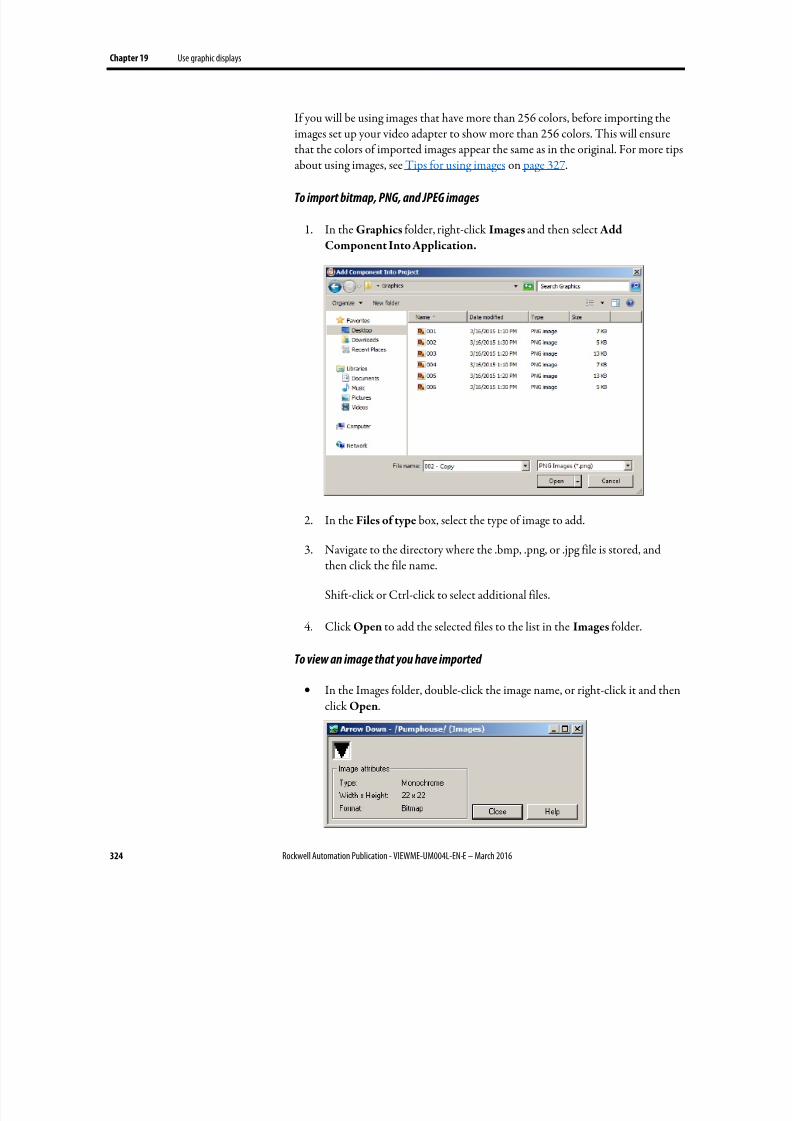
8/17/2019 FactoryTalk® View Machine Edition User's Guide
http://slidepdf.com/reader/full/factorytalk-view-machine-edition-users-guide 324/587
Chapter 19 Use graphic displays
324 Rockwell Automation Publication - VIEWME-UM004L-EN-E – March 2016
If you will be using images that have more than 256 colors, before importing theimages set up your video adapter to show more than 256 colors. This will ensurethat the colors of imported images appear the same as in the original. For more tipsabout using images, see Tips for using images on page 327.
To import bitmap, PNG, and JPEG images
1. In the Graphics folder, right-click Images and then select Add
Component Into Application.
2.
In the Files of type box, select the type of image to add.
3. Navigate to the directory where the .bmp, .png, or .jpg file is stored, andthen click the file name.
Shift-click or Ctrl-click to select additional files.
4. Click Open to add the selected files to the list in the Images folder.
To view an image that you have imported
•
In the Images folder, double-click the image name, or right-click it and thenclick Open.
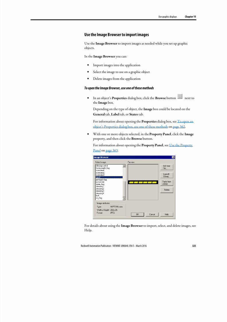
8/17/2019 FactoryTalk® View Machine Edition User's Guide
http://slidepdf.com/reader/full/factorytalk-view-machine-edition-users-guide 325/587
Use graphic displays Chapter 19
Rockwell Automation Publication - VIEWME-UM004L-EN-E – March 2016 325
Use the Image Browser to import images
Use the Image Browser to import images as needed while you set up graphic
objects.
In the Image Browser you can:
• Import images into the application
• Select the image to use on a graphic object
• Delete images from the application
To open the Image Browser, use one of these methods
•
In an object’s Properties dialog box, click the Browse button next tothe Image box.
Depending on the type of object, the Image box could be located on the
General tab, Label tab, or States tab.
For information about opening the Properties dialog box, see To open an
object’s Properties dialog box, use one of these methods on page 362.
• With one or more objects selected, in the Property Panel, click the Image
property, and then click the Browse button.
For information about opening the Property Panel, see Use the Property
Panel on page 363.
For details about using the Image Browser to import, select, and delete images, seeHelp.

8/17/2019 FactoryTalk® View Machine Edition User's Guide
http://slidepdf.com/reader/full/factorytalk-view-machine-edition-users-guide 326/587
Chapter 19 Use graphic displays
326 Rockwell Automation Publication - VIEWME-UM004L-EN-E – March 2016
You can also remove an image by right-clicking it in the Images folder, and thenselect Remove or Delete. For more information, see Remove components on page301.
Use Symbol Factory
Symbol Factory is a third-party graphics library that provides a large number ofquality graphic elements.
Import Symbol Factory objects directly into image container
1. From the Image Browser window, click the Launch Library button. This will open a Symbol Factory window.
2.
Browse through the Categories and locate the graphic to be used. Select thegraphic so it is highlighted. Click the Copy button in Symbol Factory.Symbol Factory will be minimized to the system tray.
3. From the Image Browser , click the Paste from Library button.
4.
A dialog box will open and ask for a unique image name. Type the new
name over the default text SFBitmap1.
5. Click the OK button in the Image name dialog box. The dialog box willclose returning you to the Image Browser . The new image will be shown
and the new image name shown in the image browser explorer.
6. Click the OK button in the Image Browser for the graphic to be placed inthe current workspace.
Note that any Symbol Factory object, including Bitmap, DIB and metafile can be pasted into Image Browser where it will be stored as a bitmap.
Import Symbol Factory objects directly into display
1.
Open Symbol Factory. See To open Symbol Factory on page 317.
2. Browse through the Categories and locate the graphic to be used. Select thegraphic so it is highlighted. To place the object into the display you could doone of the following:
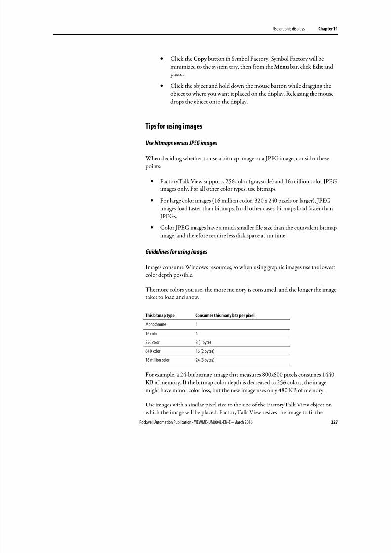
8/17/2019 FactoryTalk® View Machine Edition User's Guide
http://slidepdf.com/reader/full/factorytalk-view-machine-edition-users-guide 327/587
Use graphic displays Chapter 19
Rockwell Automation Publication - VIEWME-UM004L-EN-E – March 2016 327
• Click the Copy button in Symbol Factory. Symbol Factory will beminimized to the system tray, then from the Menu bar, click Edit and paste.
•
Click the object and hold down the mouse button while dragging theobject to where you want it placed on the display. Releasing the mousedrops the object onto the display.
Tips for using images
Use bitmaps versus JPEG images
When deciding whether to use a bitmap image or a JPEG image, consider these points:
• FactoryTalk View supports 256 color (grayscale) and 16 million color JPEGimages only. For all other color types, use bitmaps.
• For large color images (16 million color, 320 x 240 pixels or larger), JPEGimages load faster than bitmaps. In all other cases, bitmaps load faster than JPEGs.
• Color JPEG images have a much smaller file size than the equivalent bitmapimage, and therefore require less disk space at runtime.
Guidelines for using images
Images consume Windows resources, so when using graphic images use the lowestcolor depth possible.
The more colors you use, the more memory is consumed, and the longer the imagetakes to load and show.
This bitmap type Consumes this many bits per pixel
Monochrome 1
16 color 4
256 color 8 (1 byte)64 K color 16 (2 bytes)
16 million color 24 (3 bytes)
For example, a 24-bit bitmap image that measures 800x600 pixels consumes 1440KB of memory. If the bitmap color depth is decreased to 256 colors, the imagemight have minor color loss, but the new image uses only 480 KB of memory.
Use images with a similar pixel size to the size of the FactoryTalk View object on which the image will be placed. FactoryTalk View resizes the image to fit the
8/17/2019 FactoryTalk® View Machine Edition User's Guide
http://slidepdf.com/reader/full/factorytalk-view-machine-edition-users-guide 328/587
Chapter 19 Use graphic displays
328 Rockwell Automation Publication - VIEWME-UM004L-EN-E – March 2016
object, but if you use an image that is much larger than the object, the display willbe slow to open at runtime, due to the time required to resize the image.
Use local messages to give the operator ongoing information about the status of
devices and processes. For example, you might use local messages to describe thestatus of a device whose condition cannot be shown graphically with completeaccuracy.
The messages you create in the Local Messages editor are shown in local messagedisplay objects in graphic displays. You can use multiple local message displayobjects in your application, and link each object to a different file of messages. Or, you can use the same file of messages for multiple local message display objects.
Local messages versus information messages
Use local messages to give the operator information in a specific graphic display while the display is open. To give the operator information no matter whichdisplay is open, use information messages.
For details about information messages, see Use information messages on page485.
Steps for setting up local messages
Follow these steps to set up local messages:
1.
In the Local Messages editor, set up the messages and their trigger values.
2.
In the Graphics editor, create local message display objects in the graphicdisplays in which you want the messages to appear at runtime. For each local
message display, assign a tag or expression to the Value connection andspecify the file of messages to show.
For information about creating graphic objects, see Use graphic objects on
page 335.
Use local messages
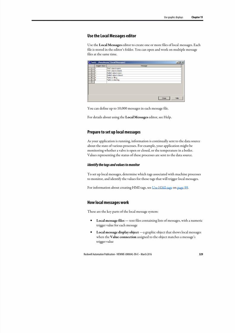
8/17/2019 FactoryTalk® View Machine Edition User's Guide
http://slidepdf.com/reader/full/factorytalk-view-machine-edition-users-guide 329/587
Use graphic displays Chapter 19
Rockwell Automation Publication - VIEWME-UM004L-EN-E – March 2016 329
Use the Local Messages editor
Use the Local Messages editor to create one or more files of local messages. Each
file is stored in the editor’s folder. You can open and work on multiple messagefiles at the same time.
You can define up to 10,000 messages in each message file.
For details about using the Local Messages editor, see Help.
Prepare to set up local messages
As your application is running, information is continually sent to the data sourceabout the state of various processes. For example, your application might bemonitoring whether a valve is open or closed, or the temperature in a boiler.
Values representing the status of these processes are sent to the data source.
Identify the tags and values to monitor
To set up local messages, determine which tags associated with machine processesto monitor, and identify the values for those tags that will trigger local messages.
For information about creating HMI tags, see Use HMI tags on page 99.
How local messages work
These are the key parts of the local message system:
• Local message files — text files containing lists of messages, with a numerictrigger value for each message
• Local message display object —a graphic object that shows local messages when the Value connection assigned to the object matches a message’strigger value
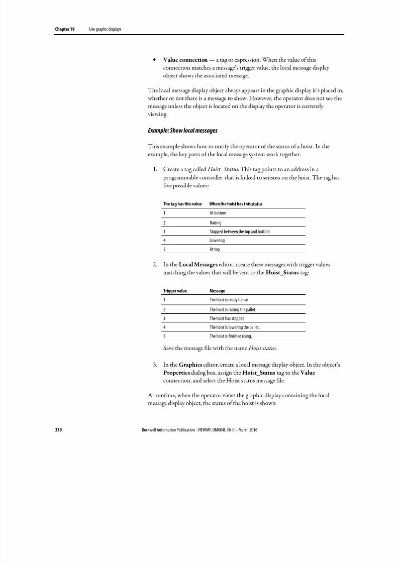
8/17/2019 FactoryTalk® View Machine Edition User's Guide
http://slidepdf.com/reader/full/factorytalk-view-machine-edition-users-guide 330/587
Chapter 19 Use graphic displays
330 Rockwell Automation Publication - VIEWME-UM004L-EN-E – March 2016
• Value connection — a tag or expression. When the value of thisconnection matches a message’s trigger value, the local message displayobject shows the associated message.
The local message display object always appears in the graphic display it’s placed in, whether or not there is a message to show. However, the operator does not see themessage unless the object is located on the display the operator is currently viewing.
Example: Show local messages
This example shows how to notify the operator of the status of a hoist. In theexample, the key parts of the local message system work together.
1. Create a tag called Hoist_Status. This tag points to an address in a
programmable controller that is linked to sensors on the hoist. The tag hasfive possible values:
The tag has this value When the hoist has this status
1 At bottom
2 Raising
3 Stopped between the top and bottom
4 Lowering
5 At top
2.
In the Local Messages editor, create these messages with trigger valuesmatching the values that will be sent to the Hoist_Status tag:
Trigger value Message
1 The hoist is ready to rise
2 The hoist is raising the pallet.
3 The hoist has stopped.
4 The hoist is lowering the pallet.
5 The hoist is finished rising.
Save the message file with the name Hoist status.
3. In the Graphics editor, create a local message display object. In the object’sProperties dialog box, assign the Hoist_Status tag to the Valueconnection, and select the Hoist status message file.
At runtime, when the operator views the graphic display containing the localmessage display object, the status of the hoist is shown.
8/17/2019 FactoryTalk® View Machine Edition User's Guide
http://slidepdf.com/reader/full/factorytalk-view-machine-edition-users-guide 331/587
Use graphic displays Chapter 19
Rockwell Automation Publication - VIEWME-UM004L-EN-E – March 2016 331
Local messages and trigger values
Create messages associated with each tag value that you want to inform the
operator about. Assign each message a trigger value, and set up the data source tosend the trigger value to the Value connection. You can use both HMI and dataserver tags
The trigger value can be any non-zero integer value (positive or negative). Trigger values do not need to be contiguous, but they must be unique for each message.For example, you could use trigger values of 1, 2, and 3, or values of 10, 20, and 30.
If you use an analog tag or an expression, you can use any non-zero integer orfloating point value to trigger an alarm. Floating point values are rounded to thenearest integer. For information about how values are rounded, see How values arerounded on page 100.
Trigger values cannot be 0. Digital tags have two possible values, 0 and 1.Therefore, if you use a digital tag you can only use the value 1 to trigger a message.If you want to use a digital tag to trigger two different messages, create anexpression that adds 1 to the digital tag’s value. That way, you can use the trigger values 1 and 2.
When the Value connection value is 0, the local message display object is cleared.
Create local messages in multiple languages
FactoryTalk View 5.00 supports local messages in multiple languages. When youcreate local messages, they are in the current application language. You can exportthe local messages for translation and then import them back into the application.For details, see Set up language switching on page 199.
Language switching local messages in FactoryTalk View ME Station 4.00
For applications that will run in FactoryTalk View ME Station version 4.00, usethe CurrentLanguage( ) expression function to specify message offsets in the localmessage file. In the file, divide your messages into sections for each language. For
information about the CurrentLanguage( ) function, see Language function on page 447.
How the local message display graphic object works
When you open a graphic display at runtime, FactoryTalk View reads the value ofthe Value connection and updates the local message display object based on the value.
8/17/2019 FactoryTalk® View Machine Edition User's Guide
http://slidepdf.com/reader/full/factorytalk-view-machine-edition-users-guide 332/587
Chapter 19 Use graphic displays
332 Rockwell Automation Publication - VIEWME-UM004L-EN-E – March 2016
What is shown
• If the Value connection is unassigned, the display is filled with questionmarks (?).
• The Value connection is rounded to the nearest integer. If the value doesnot match any of the trigger values in the specified message file, the displayis filled with question marks.
For information about how values are rounded, see How values are rounded
on page 100.
• If the message is too long to fit in the object, the last shown character isreplaced with an asterisk (*).
• When the Value connection’s value is 0, the display is cleared.
•
If you set up local messages in multiple languages, messages are shown in thecurrent application language. When a language switch occurs, the messagethat was already in the local message display remains in the language that itoriginally appeared in. New messages are shown in the new language.
You can print your graphic displays on the development computer. This might beuseful if you want other people to review the displays before implementing theapplication, or if you want to keep a visual record of the displays.
You can also print graphic displays at runtime, to provide a printed record of process values such as trend data.
For information about printing on the development computer, see Print on page51.
Print displays at runtime
When you print a display at runtime, everything on the screen is printed,including the current display, pop-up windows, and any visible backgroundapplications.
For information about specifying which printer to use at runtime for applicationsthat will run on a personal computer or a MobileView terminal, see Specify the printers to use at runtime on page 238.
For information about specifying printer options for applications that will run ona PanelView Plus 7, PanelView Plus 6, PanelView Plus, PanelView Plus Compact,or PanelView Plus CE terminal, see the PanelView Plus Terminals User Manual .
Print displays
8/17/2019 FactoryTalk® View Machine Edition User's Guide
http://slidepdf.com/reader/full/factorytalk-view-machine-edition-users-guide 333/587
Use graphic displays Chapter 19
Rockwell Automation Publication - VIEWME-UM004L-EN-E – March 2016 333
To print graphic displays at runtime
Use one or both of these methods:
•
Create display print buttons on the graphic displays you want to print. Atruntime, the operator presses the buttons to print the displays.
For information about creating graphic objects, see Use graphic objects on
page 335.
• Assign a tag or expression to the Remote Display Print connection (in theGlobal Connections editor). When the value of the tag or expressionchanges from 0 to a non-zero value, the current displays are automatically printed.
Program the data source to trigger the change as often as you want the data
printed.
For more information about setting up remote display printing, see Print
displays on page 332.

8/17/2019 FactoryTalk® View Machine Edition User's Guide
http://slidepdf.com/reader/full/factorytalk-view-machine-edition-users-guide 334/587
Chapter 19 Use graphic displays
334 Rockwell Automation Publication - VIEWME-UM004L-EN-E – March 2016
8/17/2019 FactoryTalk® View Machine Edition User's Guide
http://slidepdf.com/reader/full/factorytalk-view-machine-edition-users-guide 335/587
Rockwell Automation Publication - VIEWME-UM004L-EN-E – March 2016 335
Chapter 20
Use graphic objects
This chapter describes the types of graphic objects and outlines how to:
• Create graphic objects, including drawing and ActiveX objects
• Select and deselect objects and use the Object Explorer
• Use the Properties dialog box and Property Panel to set up objects
•
Color and name objects• Test how objects look in different states
• Assign tags and expressions to objects
• Replace tags using tag substitution
• Use tag placeholders
• Move, copy, duplicate, resize, reshape, and delete objects
• Group and ungroup objects, and edit group objects
• Arrange objects and lock objects into position
For information about setting up graphic objects once you have created them, seeSet up graphic objects on page 391.
For information about setting up global objects, see Use parameters and globalobjects on page 461.
For examples of how to set up objects, see the sample applications that come withRSLinx Classic Studio. The Help also provides examples of how to use objects.
The elements that make up a graphic display are called graphic objects. Use objectsto control your process, machines, and application.
FactoryTalk View comes with a complete range of configurable objects such as push buttons, list selectors, bar graphs, and trends. Some objects interact with thedata source, allowing the operator to change or view tag values. For example, theoperator can push a button to set a tag value to 1, causing a programmablecontroller to start a conveyor belt. Other objects are used to control yourapplication. For example, there are button objects that you can use to changedisplays and scroll through lists.
Graphic objects
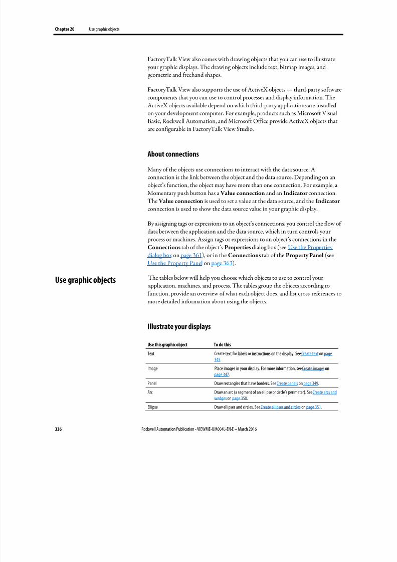
8/17/2019 FactoryTalk® View Machine Edition User's Guide
http://slidepdf.com/reader/full/factorytalk-view-machine-edition-users-guide 336/587
Chapter 20 Use graphic objects
336 Rockwell Automation Publication - VIEWME-UM004L-EN-E – March 2016
FactoryTalk View also comes with drawing objects that you can use to illustrate your graphic displays. The drawing objects include text, bitmap images, andgeometric and freehand shapes.
FactoryTalk View also supports the use of ActiveX objects — third-party softwarecomponents that you can use to control processes and display information. TheActiveX objects available depend on which third-party applications are installedon your development computer. For example, products such as Microsoft VisualBasic, Rockwell Automation, and Microsoft Office provide ActiveX objects thatare configurable in FactoryTalk View Studio.
About connections
Many of the objects use connections to interact with the data source. Aconnection is the link between the object and the data source. Depending on anobject’s function, the object may have more than one connection. For example, aMomentary push button has a Value connection and an Indicator connection.The Value connection is used to set a value at the data source, and the Indicator connection is used to show the data source value in your graphic display.
By assigning tags or expressions to an object’s connections, you control the flow ofdata between the application and the data source, which in turn controls your process or machines. Assign tags or expressions to an object’s connections in theConnections tab of the object’s Properties dialog box (see Use the Propertiesdialog box on page 361), or in the Connections tab of the Property Panel (see
Use the Property Panel on page 363).
The tables below will help you choose which objects to use to control yourapplication, machines, and process. The tables group the objects according tofunction, provide an overview of what each object does, and list cross-references tomore detailed information about using the objects.
Illustrate your displays
Use this graphic object To do this
Text Create text for labels or instructions on the display. See Create text on page345.
Image Place images in your display. For more information, see Create images onpage 347.
Panel Draw rectangles that have borders. See Create panels on page 349.
Arc Draw an arc (a segment of an ellipse or circle’s perimeter). See Create arcs andwedges on page 350.
Ellipse Draw ellipses and circles. See Create ellipses and circles on page 351.
Use graphic objects
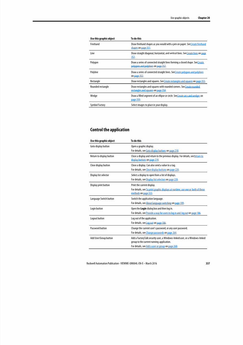
8/17/2019 FactoryTalk® View Machine Edition User's Guide
http://slidepdf.com/reader/full/factorytalk-view-machine-edition-users-guide 337/587
Use graphic objects Chapter 20
Rockwell Automation Publication - VIEWME-UM004L-EN-E – March 2016 337
Use this graphic object To do this
Freehand Draw freehand shapes as you would with a pen on paper. See Create freehandshapes on page 351.
Line Draw straight diagonal, horizontal, and vertical lines. See Create lines on page352.
Polygon Draw a series of connected straight lines forming a closed shape. See Createpolygons and polylines on page 352.
Polyline Draw a series of connected straight lines. See Create polygons and polylines on page 352.
Rectangle Draw rectangles and squares. See Create rectangles and squares on page 353.
Rounded rectangle Draw rectangles and squares with rounded corners. See Create roundedrectangles and squares on page 354.
Wedge Draw a filled segment of an ellipse or circle. See Create arcs and wedges onpage 350.
Symbol Factory Select images to place in your display.
Control the application
Use this graphic object To do this
Goto display button Open a graphic display.
For details, see Goto display buttons on page 218.
Return to display button Close a display and return to the previous display. For details, see Return to
display buttons on page 219.Close display button Close a display. Can also send a value to a tag.
For details, see Close display buttons on page 220.
Display list selector Select a display to open from a list of displays.
For details, see Display list selectors on page 220.
Display print button Print the current display.
For details, see To print graphic displays at runtime, use one or both of thesemethods on page 333.
Language Switch button Switch the application language.
For details, see About language switching on page 199.
Login button Open the Login dialog box and then log in.
For details, see Provide a way for users to log in and log out on page 186.Logout button Log out of the application.
For details, see Log out on page 186.
Password button Change the current user’s password, or any user password.
For details, see Change passwords on page 264.
Add User/Group button Add a FactoryTalk security user, a Windows-linked user, or a Windows-linkedgroup to the current running application.
For details, see Add a user or group on page 268.
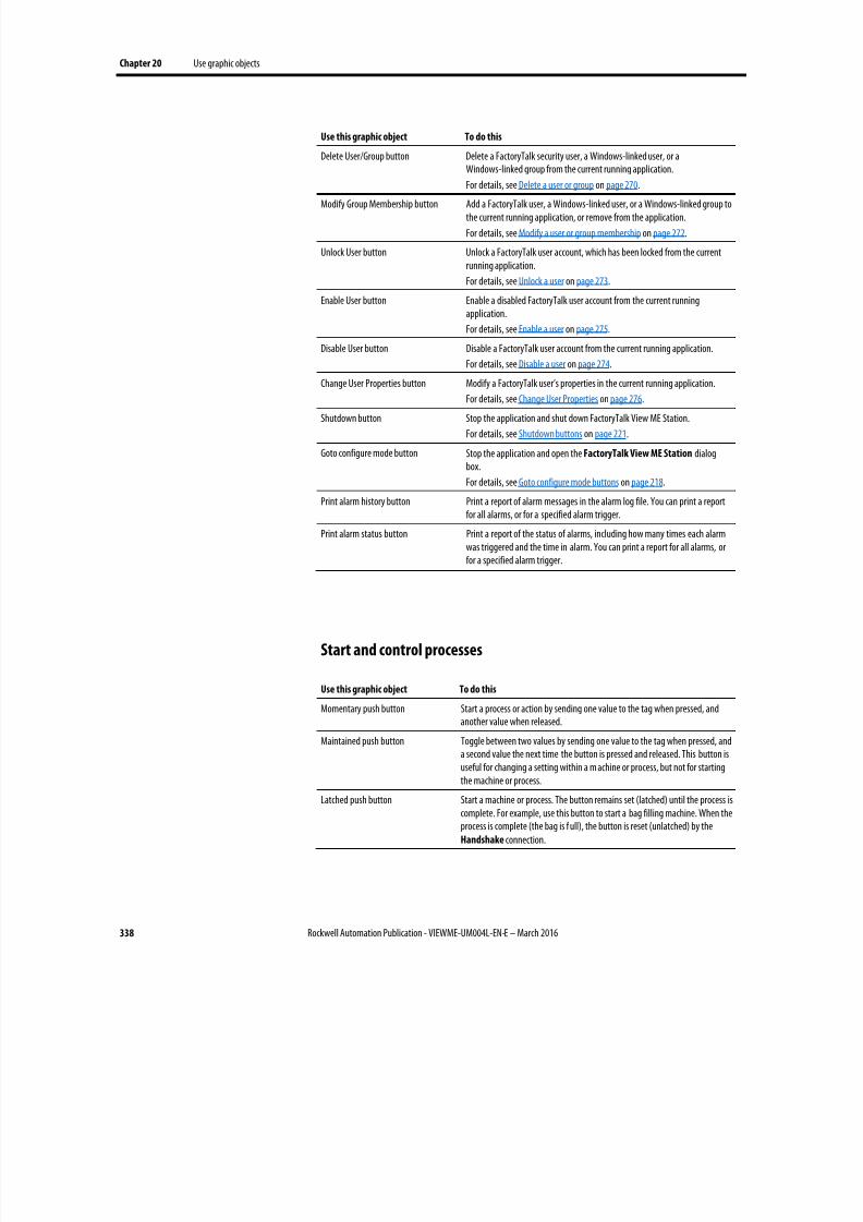
8/17/2019 FactoryTalk® View Machine Edition User's Guide
http://slidepdf.com/reader/full/factorytalk-view-machine-edition-users-guide 338/587
Chapter 20 Use graphic objects
338 Rockwell Automation Publication - VIEWME-UM004L-EN-E – March 2016
Use this graphic object To do this
Delete User/Group button Delete a FactoryTalk security user, a Windows-linked user, or aWindows-linked group from the current running application.
For details, see Delete a user or group on page 270.Modify Group Membership button Add a FactoryTalk user, a Windows-linked user, or a Windows-linked group to
the current running application, or remove from the application.
For details, see Modify a user or group membership on page 272.
Unlock User button Unlock a FactoryTalk user account, which has been locked from the currentrunning application.
For details, see Unlock a user on page 273.
Enable User button Enable a disabled FactoryTalk user account from the current runningapplication.
For details, see Enable a user on page 275.
Disable User button Disable a FactoryTalk user account from the current running application.
For details, see Disable a user on page 274.
Change User Properties button Modify a FactoryTalk user’s properties in the current running application.
For details, see Change User Properties on page 276.
Shutdown button Stop the application and shut down FactoryTalk View ME Station.
For details, see Shutdown buttons on page 221.
Goto configure mode button Stop the application and open the FactoryTalk View ME Station dialogbox.
For details, see Goto configure mode buttons on page 218.
Print alarm history button Print a report of alarm messages in the alarm log file. You can print a reportfor all alarms, or for a specified alarm trigger.
Print alarm status button Print a report of the status of alarms, including how many times each alarmwas triggered and the time in alarm. You can print a report for all alarms, orfor a specified alarm trigger.
Start and control processes
Use this graphic object To do this
Momentary push button Start a process or action by sending one value to the tag when pressed, andanother value when released.
Maintained push button Toggle between two values by sending one value to the tag when pressed, and
a second value the next time the button is pressed and released. This button isuseful for changing a setting within a m achine or process, but not for startingthe machine or process.
Latched push button Start a machine or process. The button remains set (latched) until the process iscomplete. For example, use this button to start a bag filling machine. When theprocess is complete (the bag is f ull), the button is reset (unlatched) by theHandshake connection.
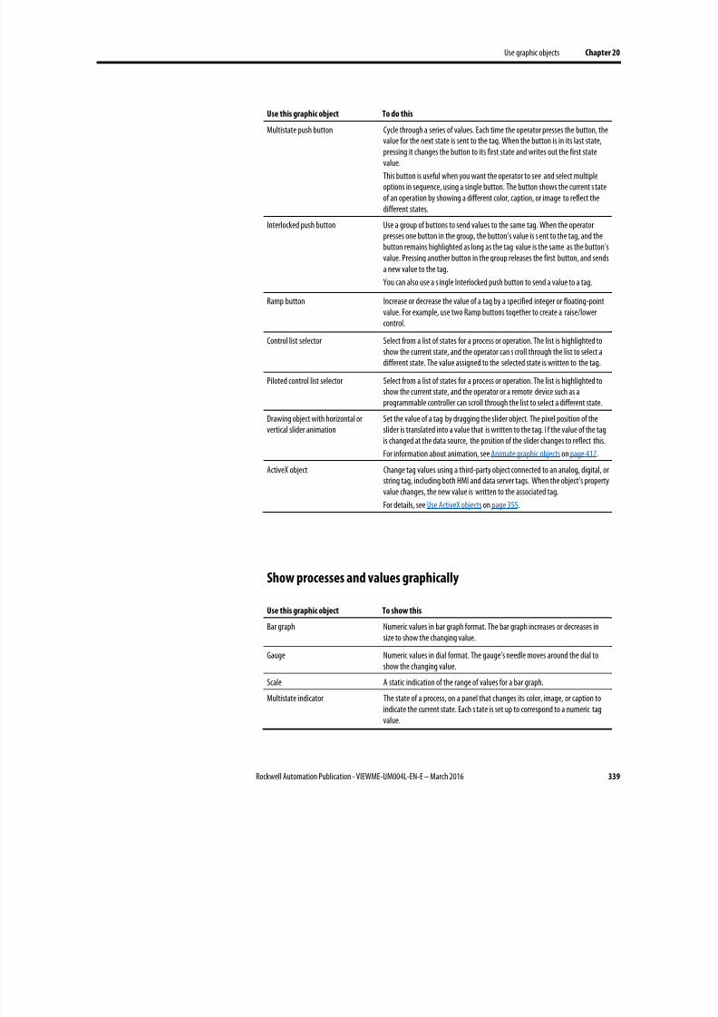
8/17/2019 FactoryTalk® View Machine Edition User's Guide
http://slidepdf.com/reader/full/factorytalk-view-machine-edition-users-guide 339/587
Use graphic objects Chapter 20
Rockwell Automation Publication - VIEWME-UM004L-EN-E – March 2016 339
Use this graphic object To do this
Multistate push button Cycle through a series of values. Each time the operator presses the button, thevalue for the next state is sent to the tag. When the button is in its last state,pressing it changes the button to its first state and writes out the first statevalue.
This button is useful when you want the operator to see and select multipleoptions in sequence, using a single button. The button shows the current s tateof an operation by showing a different color, caption, or image to reflect thedifferent states.
Interlocked push button Use a group of buttons to send values to the same tag. When the operatorpresses one button in the group, the button’s value is s ent to the tag, and thebutton remains highlighted as long as the tag value is the same as the button’svalue. Pressing another button in the group releases the first button, and sendsa new value to the tag.
You can also use a s ingle Interlocked push button to send a value to a tag.
Ramp button Increase or decrease the value of a tag by a specified integer or floating-point
value. For example, use two Ramp buttons together to create a raise/lowercontrol.
Control list selector Select from a list of states for a process or operation. The list is highlighted toshow the current state, and the operator can s croll through the list to select adifferent state. The value assigned to the selected state is written to the tag.
Piloted control list selector Select from a list of states for a process or operation. The list is highlighted toshow the current state, and the operator or a remote device such as aprogrammable controller can scroll through the list to select a different state.
Drawing object with horizontal orvertical slider animation
Set the value of a tag by dragging the slider object. The pixel position of theslider is translated into a value that is written to the tag. I f the value of the tagis changed at the data source, the position of the slider changes to reflect this.
For information about animation, see Animate graphic objects on page 417.
ActiveX object Change tag values using a third-party object connected to an analog, digital, orstring tag, including both HMI and data server tags. When the object’s propertyvalue changes, the new value is written to the associated tag.
For details, see Use ActiveX objects on page 355.
Show processes and values graphically
Use this graphic object To show this
Bar graph Numeric values in bar graph format. The bar graph increases or decreases insize to show the changing value.
Gauge Numeric values in dial format. The gauge’s needle moves around the dial toshow the changing value.
Scale A static indication of the range of values for a bar graph.
Multistate indicator The state of a process, on a panel that changes its color, image, or caption toindicate the current state. Each s tate is set up to correspond to a numeric tagvalue.
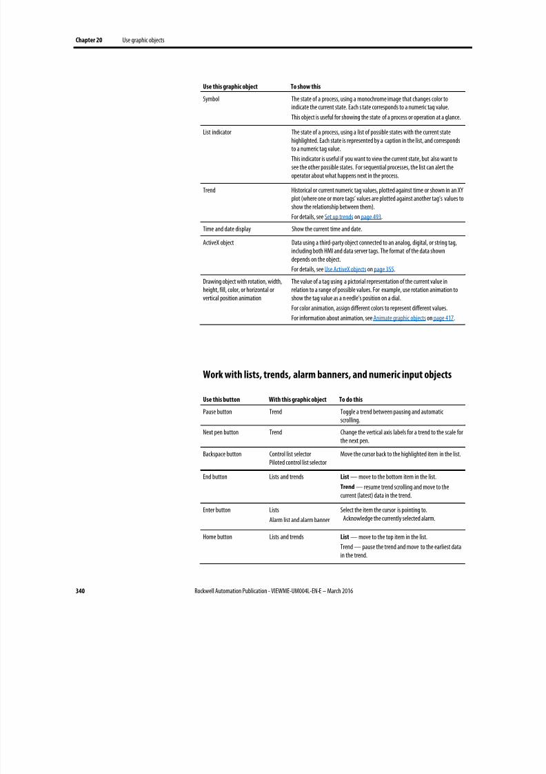
8/17/2019 FactoryTalk® View Machine Edition User's Guide
http://slidepdf.com/reader/full/factorytalk-view-machine-edition-users-guide 340/587
Chapter 20 Use graphic objects
340 Rockwell Automation Publication - VIEWME-UM004L-EN-E – March 2016
Use this graphic object To show this
Symbol The state of a process, using a monochrome image that changes color toindicate the current state. Each s tate corresponds to a numeric tag value.
This object is useful for showing the state of a process or operation at a glance.
List indicator The state of a process, using a list of possible states with the current statehighlighted. Each state is represented by a caption in the list, and correspondsto a numeric tag value.
This indicator is useful if you want to view the current state, but also want tosee the other possible states. For sequential processes, the list can alert theoperator about what happens next in the process.
Trend Historical or current numeric tag values, plotted against time or shown in an XYplot (where one or more tags’ values are plotted against another tag’s values toshow the relationship between them).
For details, see Set up trends on page 493.
Time and date display Show the current time and date.
ActiveX object Data using a third-party object connected to an analog, digital, or string tag,including both HMI and data server tags. The format of the data showndepends on the object.
For details, see Use ActiveX objects on page 355.
Drawing object with rotation, width,height, fill, color, or horizontal orvertical position animation
The value of a tag using a pictorial representation of the current value inrelation to a range of possible values. For example, use rotation animation toshow the tag value as a n eedle’s position on a dial.
For color animation, assign different colors to represent different values.
For information about animation, see Animate graphic objects on page 417.
Work with lists, trends, alarm banners, and numeric input objects
Use this button With this graphic object To do this
Pause button Trend Toggle a trend between pausing and automaticscrolling.
Next pen button Trend Change the vertical axis labels for a trend to the scale forthe next pen.
Backspace button Control list selectorPiloted control list selector
Move the cursor back to the highlighted item in the list.
End button Lists and trendsList
— move to the bottom item in the list.Trend — resume trend scrolling and move to thecurrent (latest) data in the trend.
Enter button Lists
Alarm list and alarm banner
Select the item the cursor is pointing to.Acknowledge the currently selected alarm.
Home button Lists and trends List — move to the top item in the list.
Trend — pause the trend and move to the earliest datain the trend.
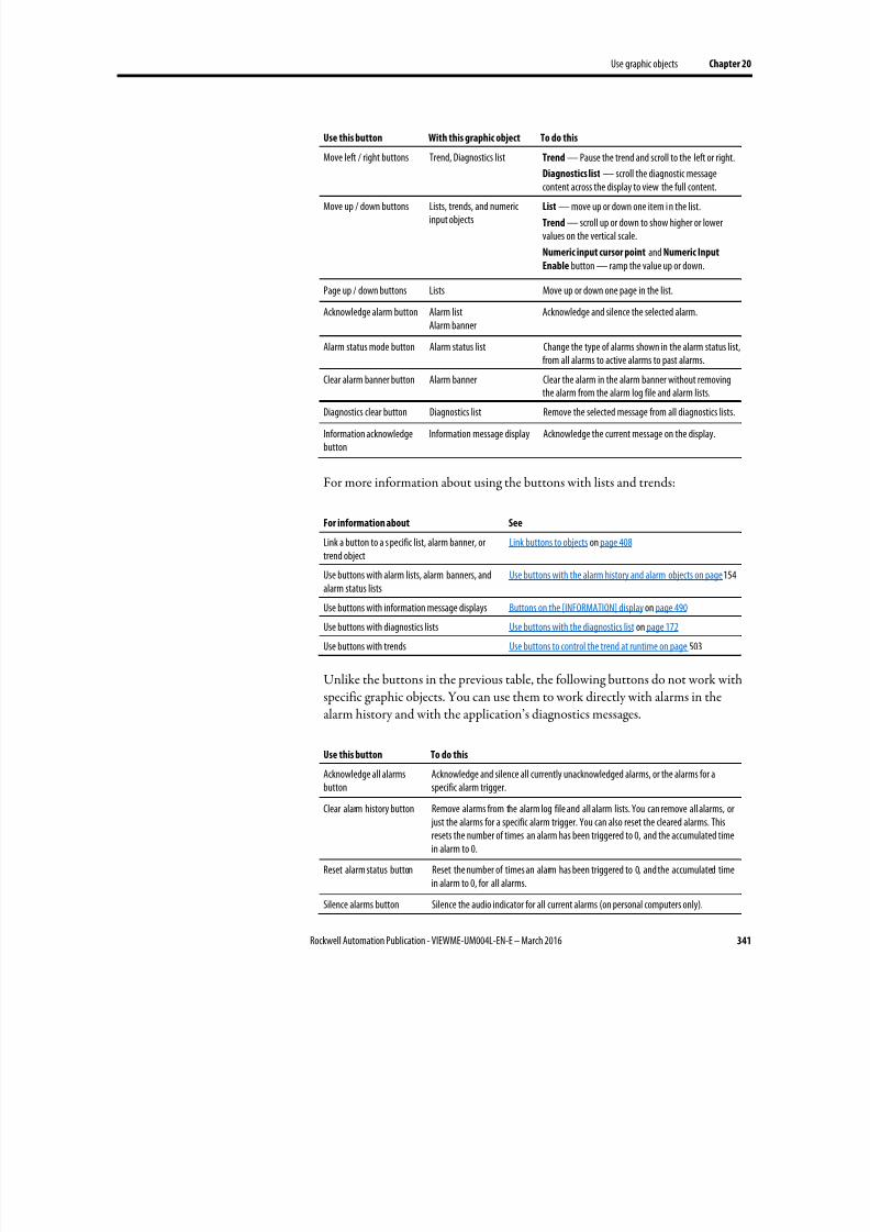
8/17/2019 FactoryTalk® View Machine Edition User's Guide
http://slidepdf.com/reader/full/factorytalk-view-machine-edition-users-guide 341/587
Use graphic objects Chapter 20
Rockwell Automation Publication - VIEWME-UM004L-EN-E – March 2016 341
Use this button With this graphic object To do this
Move left / right buttons Trend, Diagnostics list Trend — Pause the trend and scroll to the left or right.
Diagnostics list — scroll the diagnostic message
content across the display to view the full content.Move up / down buttons Lists, trends, and numeric
input objectsList — move up or down one item i n the list.
Trend — scroll up or down to show higher or lowervalues on the vertical scale.
Numeric input cursor point and Numeric Input
Enable button — ramp the value up or down.
Page up / down buttons Lists Move up or down one page in the list.
Acknowledge alarm button Alarm listAlarm banner
Acknowledge and silence the selected alarm.
Alarm status mode button Alarm status list Change the type of alarms shown in the alarm status list,from all alarms to active alarms to past alarms.
Clear alarm banner button Alarm banner Clear the alarm in the alarm banner without removingthe alarm from the alarm log file and alarm lists.
Diagnostics clear button Diagnostics list Remove the selected message from all diagnostics lists.
Information acknowledgebutton
Information message display Acknowledge the current message on the display.
For more information about using the buttons with lists and trends:
For information about See
Link a button to a s pecific list, alarm banner, ortrend object
Link buttons to objects on page 408
Use buttons with alarm lists, alarm banners, andalarm status lists
Use buttons with the alarm history and alarm objects on page 154
Use buttons with information message displays Buttons on the [INFORMATION] display on page 490
Use buttons with diagnostics lists Use buttons with the diagnostics list on page 172
Use buttons with trends Use buttons to control the trend at runtime on page 503
Unlike the buttons in the previous table, the following buttons do not work withspecific graphic objects. You can use them to work directly with alarms in thealarm history and with the application’s diagnostics messages.
Use this button To do this
Acknowledge all alarmsbutton
Acknowledge and silence all currently unacknowledged alarms, or the alarms for aspecific alarm trigger.
Clear alarm history button Remove alarms from the alarm log file and all alarm lists. You can remove all alarms, or just the alarms for a specific alarm trigger. You can also reset the cleared alarms. Thisresets the number of times an alarm has been triggered to 0, and the accumulated timein alarm to 0.
Reset alarm status button Reset the number of times an alarm has been triggered to 0, and the accumulated timein alarm to 0, for all alarms.
Silence alarms button Silence the audio indicator for all current alarms (on personal computers only).
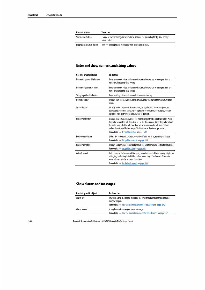
8/17/2019 FactoryTalk® View Machine Edition User's Guide
http://slidepdf.com/reader/full/factorytalk-view-machine-edition-users-guide 342/587
Chapter 20 Use graphic objects
342 Rockwell Automation Publication - VIEWME-UM004L-EN-E – March 2016
Use this button To do this
Sort alarms button Toggle between sorting alarms in alarm lists and the alarm log file by time and bytrigger value.
Diagnostics clear all button Remove all diagnostics messages from all diagnostic lists.
Enter and show numeric and string values
Use this graphic object To do this
Numeric input enable button Enter a numeric value and then write the value to a tag or an expression, orramp a value at the data source.
Numeric input cursor point Enter a numeric value and then write the value to a tag or an expression, or
ramp a value at the data source.
String Input Enable button Enter a string value and then write the value to a tag.
Numeric display Display numeric tag values. For example, show the current temperature of anoven.
String display Display string tag values. For example, set up the data source to generatestrings that report on the state of a process of operation, or that provide theoperator with instructions about what to do next.
RecipePlus button Display data set and tag values for ingredients in the RecipePlus table. Writetag values from the selected data set to the data source. Write tag values fromthe data source to the selected data set or to a new data set. Save data setvalues from the table to a recipe file. Rename or delete recipe units.
For details, see RecipePlus button on page 507.
RecipePlus selector Select the recipe unit to show, download from, write to, rename, or delete.
For details, see RecipePlus selector on page 506.
RecipePlus table Display and compare recipe data set values and tag values. Edit data set values
For details, see RecipePlus table on page 506.
ActiveX object Enter or show data using a third-party object connected to an analog, digital, orstring tag, including both HMI and data server tags. The format of the dataentered or shown depends on the object.
For details, see Use ActiveX objects on page 355.
Show alarms and messages
Use this graphic object To show this
Alarm list Multiple alarm messages, including the time the alarms are triggered andacknowledged.
For details, see How the alarm list graphic object works on page 150.
Alarm banner A single unacknowledged alarm message.
For details, see How the alarm banner graphic object works on page 152.
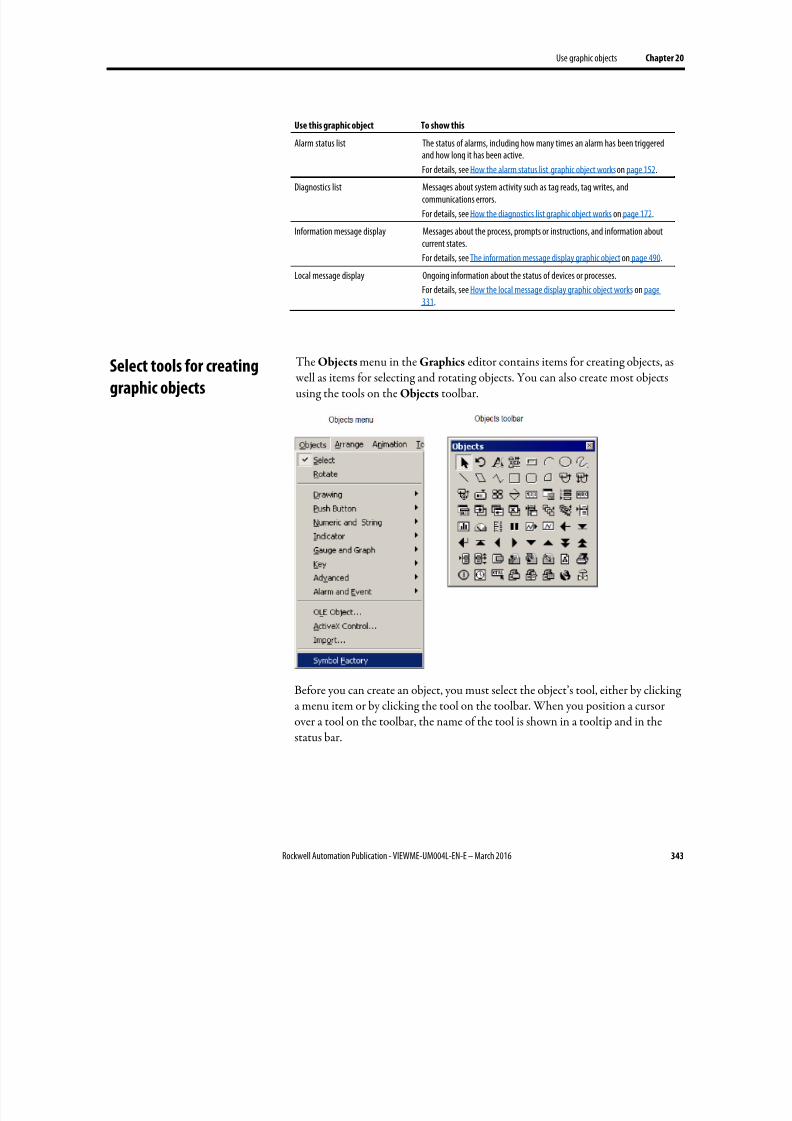
8/17/2019 FactoryTalk® View Machine Edition User's Guide
http://slidepdf.com/reader/full/factorytalk-view-machine-edition-users-guide 343/587
Use graphic objects Chapter 20
Rockwell Automation Publication - VIEWME-UM004L-EN-E – March 2016 343
Use this graphic object To show this
Alarm status list The status of alarms, including how many times an alarm has been triggeredand how long it has been active.
For details, see How the alarm status list graphic object works on page 152.Diagnostics list Messages about system activity such as tag reads, tag writes, and
communications errors.
For details, see How the diagnostics list graphic object works on page 172.
Information message display Messages about the process, prompts or instructions, and information aboutcurrent states.
For details, see The information message display graphic object on page 490.
Local message display Ongoing information about the status of devices or processes.
For details, see How the local message display graphic object works on page331.
The Objects menu in the Graphics editor contains items for creating objects, as well as items for selecting and rotating objects. You can also create most objectsusing the tools on the Objects toolbar.
Before you can create an object, you must select the object’s tool, either by clickinga menu item or by clicking the tool on the toolbar. When you position a cursorover a tool on the toolbar, the name of the tool is shown in a tooltip and in thestatus bar.
Select tools for creating
graphic objects
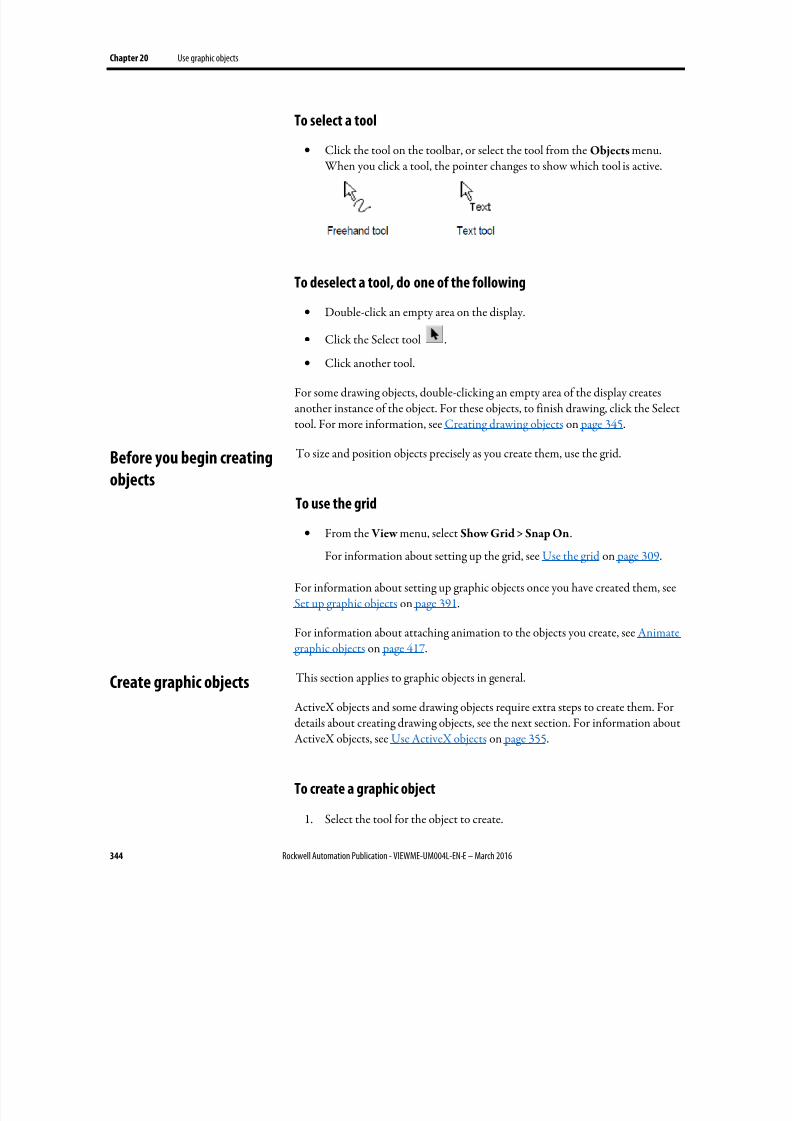
8/17/2019 FactoryTalk® View Machine Edition User's Guide
http://slidepdf.com/reader/full/factorytalk-view-machine-edition-users-guide 344/587
Chapter 20 Use graphic objects
344 Rockwell Automation Publication - VIEWME-UM004L-EN-E – March 2016
To select a tool
• Click the tool on the toolbar, or select the tool from the Objects menu. When you click a tool, the pointer changes to show which tool is active.
To deselect a tool, do one of the following
• Double-click an empty area on the display.
• Click the Select tool .
• Click another tool.
For some drawing objects, double-clicking an empty area of the display createsanother instance of the object. For these objects, to finish drawing, click the Selecttool. For more information, see Creating drawing objects on page 345.
To size and position objects precisely as you create them, use the grid.
To use the grid
• From the View menu, select Show Grid > Snap On.
For information about setting up the grid, see Use the grid on page 309.
For information about setting up graphic objects once you have created them, seeSet up graphic objects on page 391.
For information about attaching animation to the objects you create, see Animategraphic objects on page 417.
This section applies to graphic objects in general.
ActiveX objects and some drawing objects require extra steps to create them. Fordetails about creating drawing objects, see the next section. For information aboutActiveX objects, see Use ActiveX objects on page 355.
To create a graphic object
1. Select the tool for the object to create.
Before you begin creating
objects
Create graphic objects

8/17/2019 FactoryTalk® View Machine Edition User's Guide
http://slidepdf.com/reader/full/factorytalk-view-machine-edition-users-guide 345/587
Use graphic objects Chapter 20
Rockwell Automation Publication - VIEWME-UM004L-EN-E – March 2016 345
2. Click the mouse where you want to position the object, and then drag todraw a rectangle the general size you want the object to be.
3. Double-click the object to open its Properties dialog box.
4. In the dialog box, specify how the object looks, its behavior, andconnections. For more information about the Properties dialog box, seeUse the Properties dialog box on page 361.
You can also use the Property Panel to set up objects. For information
about using the Property Panel, see Use the Property Panel on page 363.
The following instructions for creating drawing objects describe how to create theobjects and then open the objects’ Properties dialog boxes to set up how theobjects look. For information about using the Properties dialog box, see Use the
Properties dialog box on page 361.
You can also use the Property Panel to set up objects. For information aboutusing the Property Panel, see Use the Property Panel on page 363.
Create text
Choose fonts
You can select any font you have installed, but TrueType and OpenType fontsare recommended. These fonts can be resized easily, without losing text quality.
For PanelView Plus and PanelView Plus CE terminals, you must use TrueTypefonts.
If you run an application on a computer that does not have the fonts you used when setting up the application, Windows substitutes with the fonts that mostclosely match the fonts you specified.
Choose fonts for language switching
If you are going to use the application with multiple languages, we recommendusing Microsoft Sans Serif or Tahoma. These fonts allow for font linking tosupport the character sets of other languages. PanelView Plus 7, PanelView Plus 6,PanelView Plus, PanelView Plus Compact, and PanelView Plus CE terminals areshipped with font linking turned on.
For more information about font linking, see Help. For more information aboutsetting up languages for your application, see Set up language switching on page199.
Create drawing objects
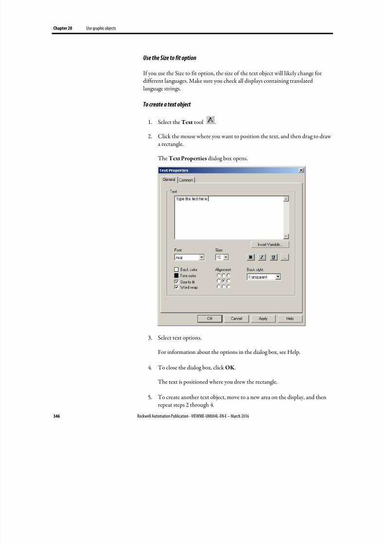
8/17/2019 FactoryTalk® View Machine Edition User's Guide
http://slidepdf.com/reader/full/factorytalk-view-machine-edition-users-guide 346/587
Chapter 20 Use graphic objects
346 Rockwell Automation Publication - VIEWME-UM004L-EN-E – March 2016
Use the Size to fit option
If you use the Size to fit option, the size of the text object will likely change fordifferent languages. Make sure you check all displays containing translatedlanguage strings.
To create a text object
1. Select the Text tool .
2. Click the mouse where you want to position the text, and then drag to drawa rectangle.
The Text Properties dialog box opens.
3.
Select text options.
For information about the options in the dialog box, see Help.
4. To close the dialog box, click OK .
The text is positioned where you drew the rectangle.
5. To create another text object, move to a new area on the display, and thenrepeat steps 2 through 4.
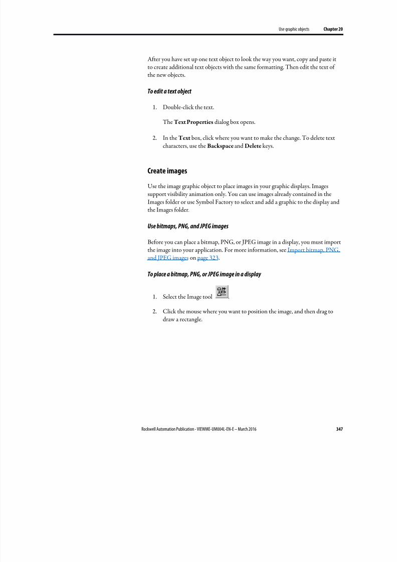
8/17/2019 FactoryTalk® View Machine Edition User's Guide
http://slidepdf.com/reader/full/factorytalk-view-machine-edition-users-guide 347/587
Use graphic objects Chapter 20
Rockwell Automation Publication - VIEWME-UM004L-EN-E – March 2016 347
After you have set up one text object to look the way you want, copy and paste itto create additional text objects with the same formatting. Then edit the text ofthe new objects.
To edit a text object
1. Double-click the text.
The Text Properties dialog box opens.
2. In the Text box, click where you want to make the change. To delete textcharacters, use the Backspace and Delete keys.
Create imagesUse the image graphic object to place images in your graphic displays. Imagessupport visibility animation only. You can use images already contained in theImages folder or use Symbol Factory to select and add a graphic to the display andthe Images folder.
Use bitmaps, PNG, and JPEG images
Before you can place a bitmap, PNG, or JPEG image in a display, you must importthe image into your application. For more information, see Import bitmap, PNG,and JPEG images on page 323.
To place a bitmap, PNG, or JPEG image in a display
1. Select the Image tool .
2. Click the mouse where you want to position the image, and then drag todraw a rectangle.
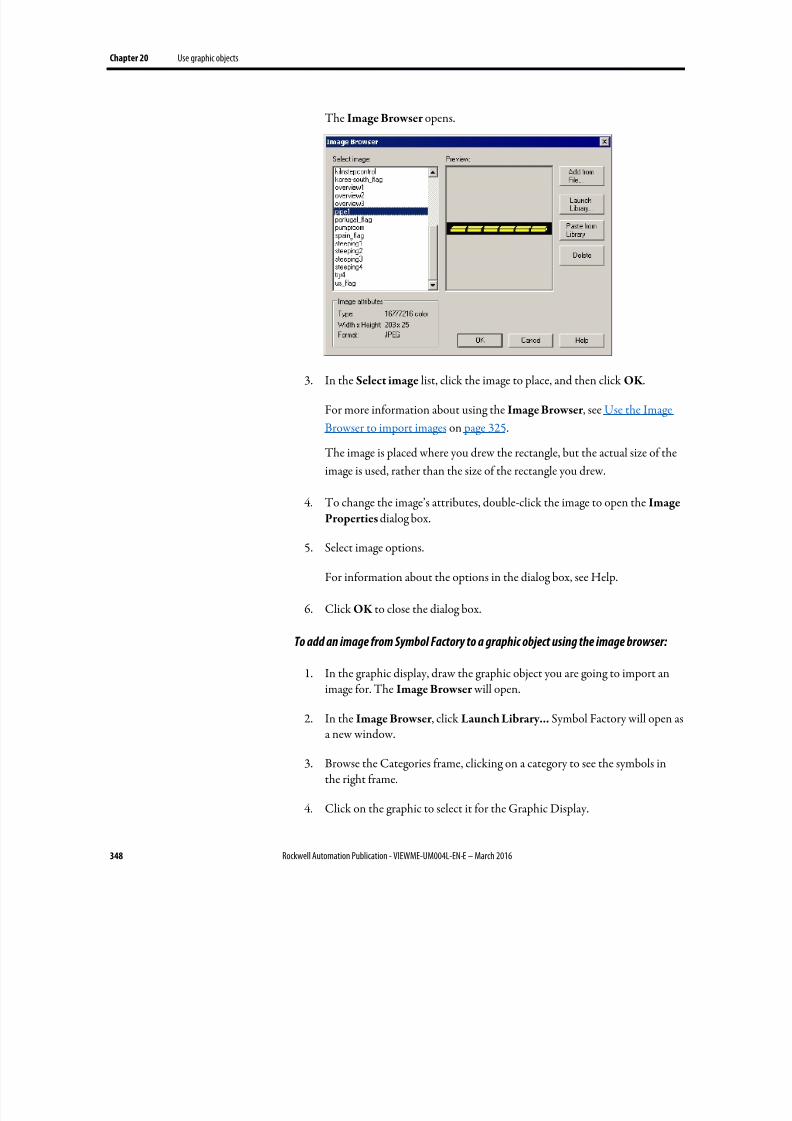
8/17/2019 FactoryTalk® View Machine Edition User's Guide
http://slidepdf.com/reader/full/factorytalk-view-machine-edition-users-guide 348/587
Chapter 20 Use graphic objects
348 Rockwell Automation Publication - VIEWME-UM004L-EN-E – March 2016
The Image Browser opens.
3. In the Select image list, click the image to place, and then click OK .
For more information about using the Image Browser , see Use the Image
Browser to import images on page 325.
The image is placed where you drew the rectangle, but the actual size of the
image is used, rather than the size of the rectangle you drew.
4. To change the image’s attributes, double-click the image to open the Image
Properties dialog box.
5. Select image options.
For information about the options in the dialog box, see Help.
6. Click OK to close the dialog box.
To add an image from Symbol Factory to a graphic object using the image browser:
1. In the graphic display, draw the graphic object you are going to import an
image for. The Image Browser will open.
2. In the Image Browser , click Launch Library... Symbol Factory will open asa new window.
3.
Browse the Categories frame, clicking on a category to see the symbols inthe right frame.
4. Click on the graphic to select it for the Graphic Display.

8/17/2019 FactoryTalk® View Machine Edition User's Guide
http://slidepdf.com/reader/full/factorytalk-view-machine-edition-users-guide 349/587
Use graphic objects Chapter 20
Rockwell Automation Publication - VIEWME-UM004L-EN-E – March 2016 349
5. Click Copy , the Symbol Factory minimizes, returning to the Image
Browser .
6.
Click the Paste from Library button. A dialog box Image Name Entry will
open.
7. Type in an unique name for the image, then click the OK button.
8. The graphic will now be shown in the Preview window. The graphic hasbeen added to the list in the Image Browser . This also adds the image to theImages folder in the Explorer window.
9. Click OK to close the Image Browser . The image will be in the GraphicDisplay.
Symbol Factory objects imported by the Image Browser will by saved in theImages folder as a bitmap.
Create panels
Panels support visibility animation only.
To create a panel
1.
Select the Panel tool .
2.
Click the mouse where you want to position the panel, and then drag todraw a rectangle the general size you want the panel to be.
3. To change how the panel looks, double-click the panel to open the Panel
Properties dialog box.
4. Select panel options.
For information about the options in the dialog box, see Help.
5.
To close the dialog box, click OK .

8/17/2019 FactoryTalk® View Machine Edition User's Guide
http://slidepdf.com/reader/full/factorytalk-view-machine-edition-users-guide 350/587
Chapter 20 Use graphic objects
350 Rockwell Automation Publication - VIEWME-UM004L-EN-E – March 2016
Create arcs and wedges
Arcs and wedges are drawn in two steps: first you create an ellipse or circle, and
then you reshape it into the segment you want.
To create an arc or wedge
1. Select the Arc or Wedge tool .
2. Click the mouse where you want to position the object, and then drag todraw an ellipse or circle.
To base the arc or wedge on a circle rather than an ellipse, hold down Ctrl
while you drag.
When you release the mouse button, a set of handles appears so you can
decrease the angle of the wedge or arc from 360 degrees to the desired angle.
3. Click a handle, and drag the mouse to ‘cut out’ part of the circle.
4. To finish drawing, click the object.
5.
To change how the object looks, click Properties on the context menu, ordouble-click the object to open its Properties dialog box.
6. Select arc or wedge options.
For information about the options in the dialog box, see Help.
7. To close the dialog box, click OK .

8/17/2019 FactoryTalk® View Machine Edition User's Guide
http://slidepdf.com/reader/full/factorytalk-view-machine-edition-users-guide 351/587
Use graphic objects Chapter 20
Rockwell Automation Publication - VIEWME-UM004L-EN-E – March 2016 351
You can also use the Arc and Wedge tools to reshape arcs and wedges. For moreinformation, see Reshape drawing objects on page 380.
Create ellipses and circles
Use the Ellipse tool to draw an ellipse or circle.
To create an ellipse or circle
1. Select the Ellipse tool .
2. Click the mouse where you want to position the object, and then drag todraw an ellipse or circle of the desired size.
To draw a circle, hold down Ctrl while you drag.
3. To change how the object looks, double-click it to open the object’sProperties dialog box.
4. Select circle or ellipse options.
For information about the options in the dialog box, see Help.
5. To close the dialog box, click OK .
Create freehand shapes
Using the Freehand tool is similar to drawing with a pen on paper.
To create a freehand shape
1.
Select the Freehand tool .
2. Click and drag to create the shape you want.
3.
To change how the object looks, double-click it to open the Freehand
Properties dialog box.
4. Select freehand options.
For information about the options in the dialog box, see Help.
5. To close the dialog box, click OK .
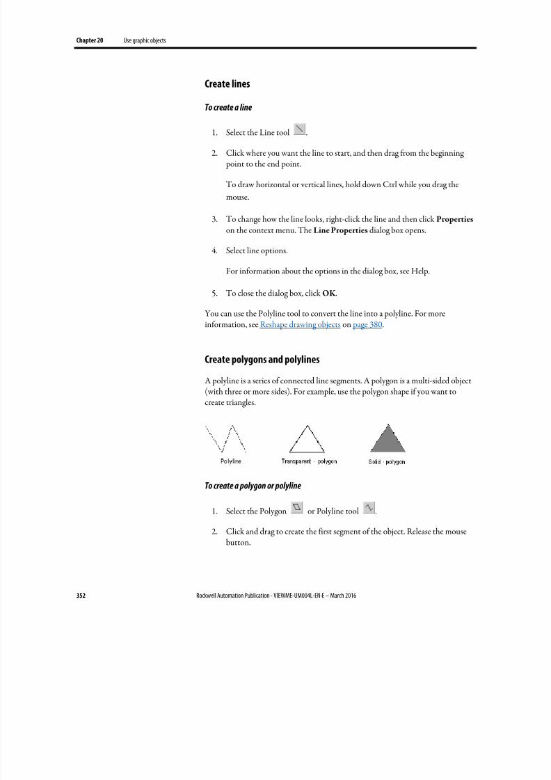
8/17/2019 FactoryTalk® View Machine Edition User's Guide
http://slidepdf.com/reader/full/factorytalk-view-machine-edition-users-guide 352/587
Chapter 20 Use graphic objects
352 Rockwell Automation Publication - VIEWME-UM004L-EN-E – March 2016
Create lines
To create a line
1.
Select the Line tool .
2. Click where you want the line to start, and then drag from the beginning point to the end point.
To draw horizontal or vertical lines, hold down Ctrl while you drag the
mouse.
3. To change how the line looks, right-click the line and then click Properties on the context menu. The Line Properties dialog box opens.
4. Select line options.
For information about the options in the dialog box, see Help.
5. To close the dialog box, click OK .
You can use the Polyline tool to convert the line into a polyline. For moreinformation, see Reshape drawing objects on page 380.
Create polygons and polylinesA polyline is a series of connected line segments. A polygon is a multi-sided object(with three or more sides). For example, use the polygon shape if you want tocreate triangles.
To create a polygon or polyline
1. Select the Polygon or Polyline tool .
2. Click and drag to create the first segment of the object. Release the mousebutton.
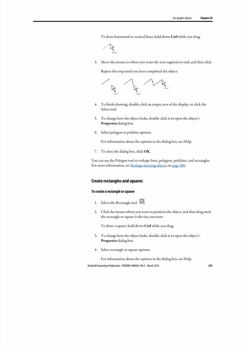
8/17/2019 FactoryTalk® View Machine Edition User's Guide
http://slidepdf.com/reader/full/factorytalk-view-machine-edition-users-guide 353/587
Use graphic objects Chapter 20
Rockwell Automation Publication - VIEWME-UM004L-EN-E – March 2016 353
To draw horizontal or vertical lines, hold down Ctrl while you drag.
3.
Move the mouse to where you want the next segment to end, and then click.
Repeat this step until you have completed the object.
4. To finish drawing, double-click an empty area of the display, or click the
Select tool.
5. To change how the object looks, double-click it to open the object’sProperties dialog box.
6. Select polygon or polyline options.
For information about the options in the dialog box, see Help.
7. To close the dialog box, click OK .
You can use the Polygon tool to reshape lines, polygons, polylines, and rectangles.For more information, see Reshape drawing objects on page 380.
Create rectangles and squares
To create a rectangle or square
1. Select the Rectangle tool .
2. Click the mouse where you want to position the object, and then drag until
the rectangle or square is the size you want.
To draw a square, hold down Ctrl while you drag.
3. To change how the object looks, double-click it to open the object’sProperties dialog box.
4. Select rectangle or square options.
For information about the options in the dialog box, see Help.
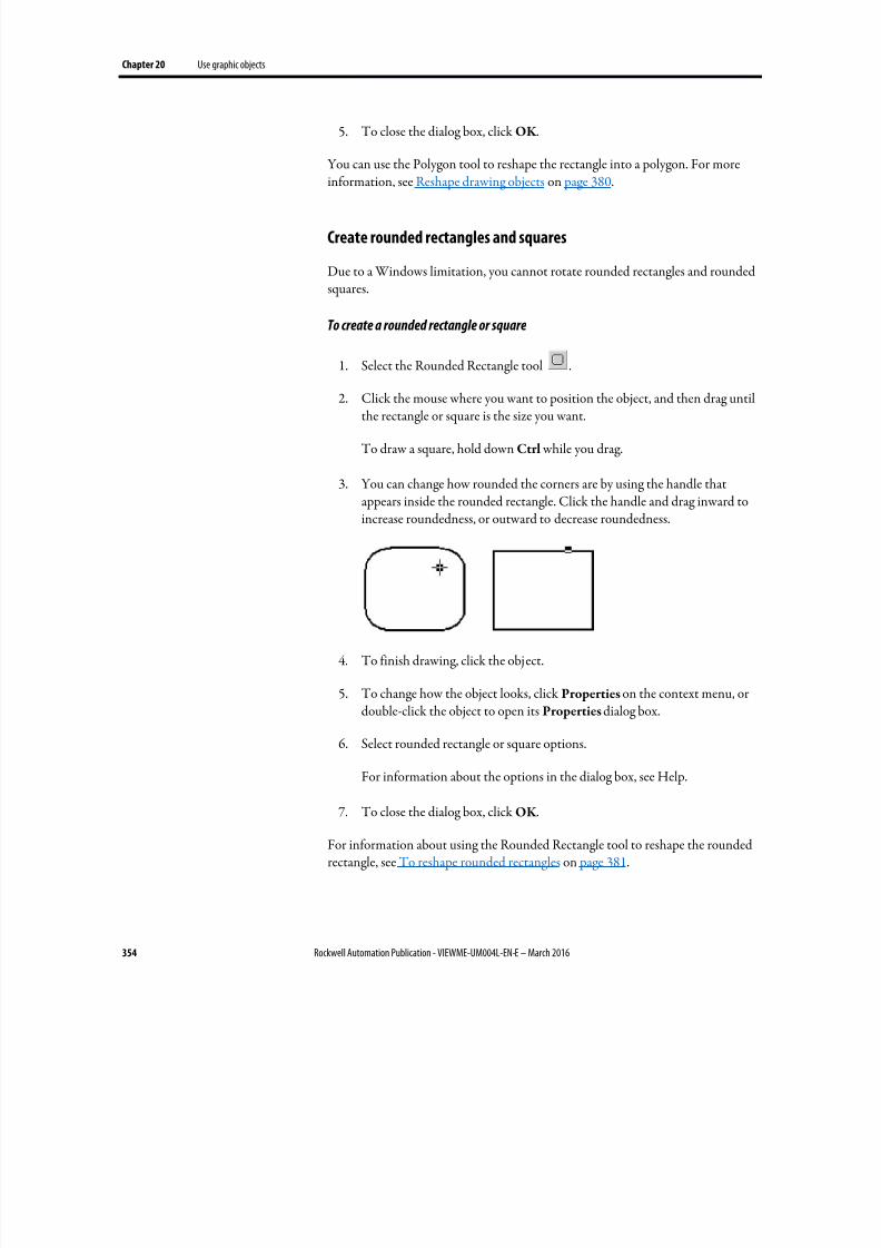
8/17/2019 FactoryTalk® View Machine Edition User's Guide
http://slidepdf.com/reader/full/factorytalk-view-machine-edition-users-guide 354/587
Chapter 20 Use graphic objects
354 Rockwell Automation Publication - VIEWME-UM004L-EN-E – March 2016
5. To close the dialog box, click OK .
You can use the Polygon tool to reshape the rectangle into a polygon. For moreinformation, see Reshape drawing objects on page 380.
Create rounded rectangles and squares
Due to a Windows limitation, you cannot rotate rounded rectangles and roundedsquares.
To create a rounded rectangle or square
1. Select the Rounded Rectangle tool .
2. Click the mouse where you want to position the object, and then drag untilthe rectangle or square is the size you want.
To draw a square, hold down Ctrl while you drag.
3. You can change how rounded the corners are by using the handle thatappears inside the rounded rectangle. Click the handle and drag inward toincrease roundedness, or outward to decrease roundedness.
4. To finish drawing, click the object.
5. To change how the object looks, click Properties on the context menu, ordouble-click the object to open its Properties dialog box.
6. Select rounded rectangle or square options.
For information about the options in the dialog box, see Help.
7. To close the dialog box, click OK .
For information about using the Rounded Rectangle tool to reshape the roundedrectangle, see To reshape rounded rectangles on page 381.
8/17/2019 FactoryTalk® View Machine Edition User's Guide
http://slidepdf.com/reader/full/factorytalk-view-machine-edition-users-guide 355/587
Use graphic objects Chapter 20
Rockwell Automation Publication - VIEWME-UM004L-EN-E – March 2016 355
Use .wmf and .dxf files
Windows metafiles (.wmf) and AutoCAD (.dxf) files are converted to drawing
objects (such as lines, ellipses, and polygons) when you import them. You can editthe drawing objects the same way you edit drawing objects that you create inFactoryTalk View.
Depending on the complexity of the metafile or AutoCAD file, the convertedimage could consist of 500 or more drawing objects. This would lead to longdisplay load times. In this case, it would be better to covert the .wmf or .dxf file to abitmap, and then show the bitmap in an image object.
To place a .wmf or .dxf file in a display
1. From the Objects menu, select Import.
2. Click the mouse where you want to position the file, and then drag to drawa rectangle.
3. In the Files of type box, select the type of file to import.
4. Navigate to the directory where the file is stored, and then click the file toimport.
5. Click Open.
The file is converted to drawing objects and grouped, and then the groupedobject is placed in the graphic display.
Use ActiveX objects
ActiveX objects use tags or expressions to exchange information with the datasource.
The properties and connections available for a particular ActiveX object dependon the third-party vendor’s implementation.
ActiveX objects support visibility animation only.
If your application will run on a PanelView Plus CE terminal, the ActiveX objectmust be available for both the development system (running on Windows 7, Windows 8, Windows 8.1, Windows Server 2008, and Windows Server 2012)and the PanelView Plus CE terminal platform. Make sure you install and registerthe Windows CE version of the ActiveX object on the PanelView Plus CE.
PanelView Plus terminals do not support ActiveX objects.
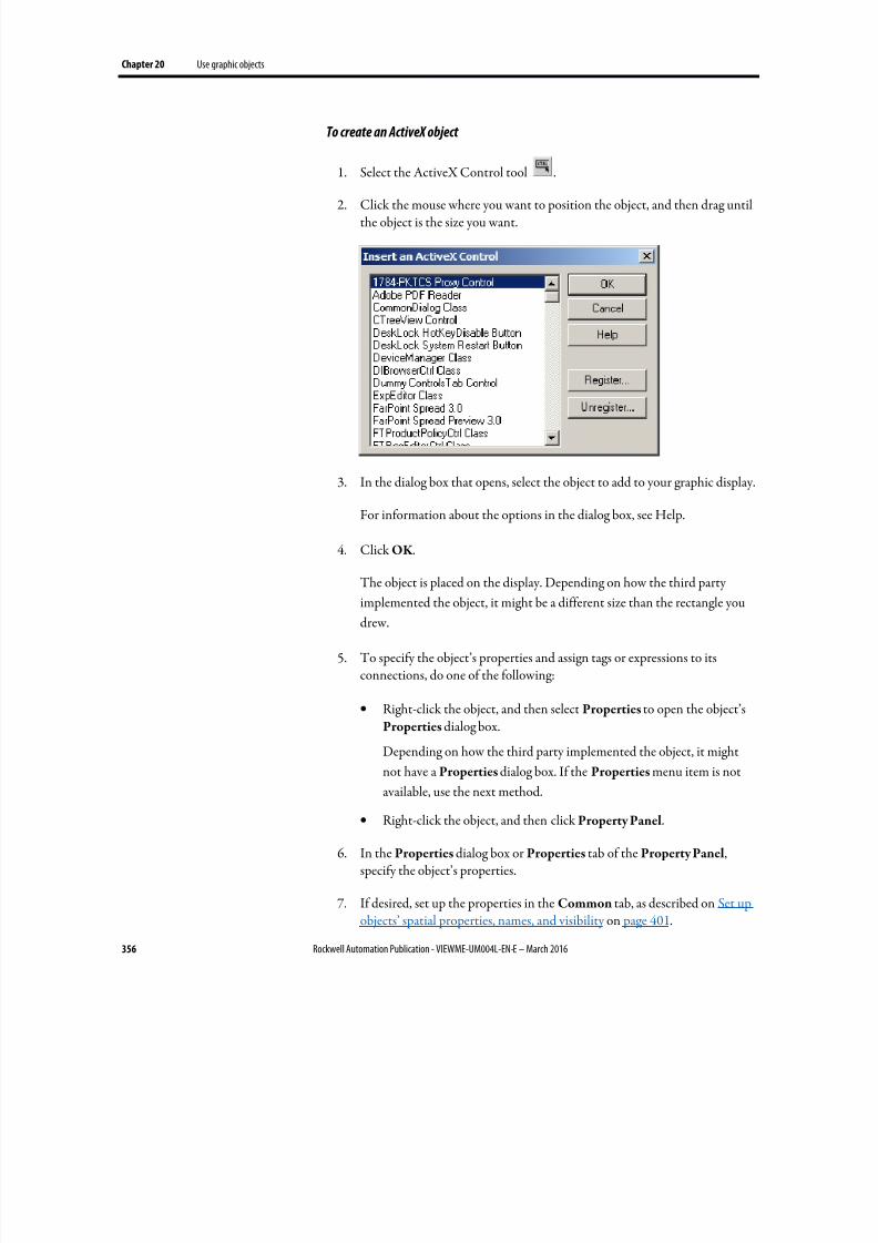
8/17/2019 FactoryTalk® View Machine Edition User's Guide
http://slidepdf.com/reader/full/factorytalk-view-machine-edition-users-guide 356/587
Chapter 20 Use graphic objects
356 Rockwell Automation Publication - VIEWME-UM004L-EN-E – March 2016
To create an ActiveX object
1. Select the ActiveX Control tool .
2. Click the mouse where you want to position the object, and then drag untilthe object is the size you want.
3. In the dialog box that opens, select the object to add to your graphic display.
For information about the options in the dialog box, see Help.
4. Click OK .
The object is placed on the display. Depending on how the third partyimplemented the object, it might be a different size than the rectangle you
drew.
5. To specify the object’s properties and assign tags or expressions to itsconnections, do one of the following:
• Right-click the object, and then select Properties to open the object’sProperties dialog box.
Depending on how the third party implemented the object, it might
not have a Properties dialog box. If the Properties menu item is notavailable, use the next method.
• Right-click the object, and then click Property Panel.
6. In the Properties dialog box or Properties tab of the Property Panel,specify the object’s properties.
7. If desired, set up the properties in the Common tab, as described on Set upobjects’ spatial properties, names, and visibility on page 401.
8/17/2019 FactoryTalk® View Machine Edition User's Guide
http://slidepdf.com/reader/full/factorytalk-view-machine-edition-users-guide 357/587
Use graphic objects Chapter 20
Rockwell Automation Publication - VIEWME-UM004L-EN-E – March 2016 357
8. In the Connections tab, assign tags or expressions to the object’sconnections.
9. To close the Properties dialog box, click OK . To close the Property Panel,
click the Close button.
For information about using the Properties dialog box, see Use the Propertiesdialog box on page 361.
For information about using the Property Panel, see Use the Property Panel on page 363.
This section describes features of the Graphics editor that help you work with theobjects you create. It describes how to:
•
Select and deselect objects.• Use the Object Explorer to view and select objects.
• Use an object’s Properties dialog box to set up the object’s properties andassign tags and expressions to its connections.
• Use the Property Panel to set up individual and group object properties,and to assign tags and expressions to individual objects’ connections.
• Color objects.
• Name objects.
•
Test how objects look in different states.
Select and deselect objects
To work with an object, you must first select it. You can use the Select tool or theObject Explorer to select objects.
For information about using the Object Explorer , see Use the Object Explorer on page 358.
To select the Select tool
• From the Objects menu, select Select, or on the Objects toolbar, click .
The mouse pointer changes to a single arrow.
Tools and tips for working
with objects
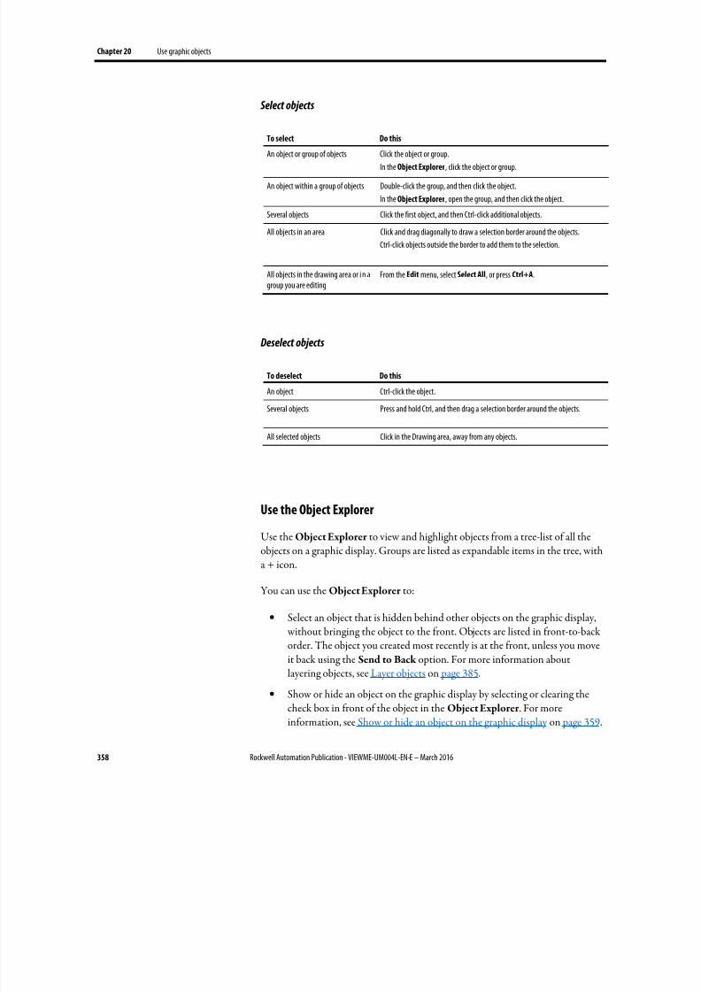
8/17/2019 FactoryTalk® View Machine Edition User's Guide
http://slidepdf.com/reader/full/factorytalk-view-machine-edition-users-guide 358/587
Chapter 20 Use graphic objects
358 Rockwell Automation Publication - VIEWME-UM004L-EN-E – March 2016
Select objects
To select Do this
An object or group of objects Click the object or group.In the Object Explorer, click the object or group.
An object within a group of objects Double-click the group, and then click the object.
In the Object Explorer, open the group, and then click the object.
Several objects Click the first object, and then Ctrl-click additional objects.
All objects in an area Click and drag diagonally to draw a selection border around the objects.
Ctrl-click objects outside the border to add them to the selection.
All objects in the drawing area or i n agroup you are editing
From the Edit menu, select Select All, or press Ctrl+A.
Deselect objects
To deselect Do this
An object Ctrl-click the object.
Several objects Press and hold Ctrl, and then drag a selection border around the objects.
All selected objects Click in the Drawing area, away from any objects.
Use the Object Explorer
Use the Object Explorer to view and highlight objects from a tree-list of all theobjects on a graphic display. Groups are listed as expandable items in the tree, witha + icon.
You can use the Object Explorer to:
•
Select an object that is hidden behind other objects on the graphic display, without bringing the object to the front. Objects are listed in front-to-backorder. The object you created most recently is at the front, unless you moveit back using the Send to Back option. For more information aboutlayering objects, see Layer objects on page 385.
• Show or hide an object on the graphic display by selecting or clearing thecheck box in front of the object in the Object Explorer . For moreinformation, see Show or hide an object on the graphic display on page 359.
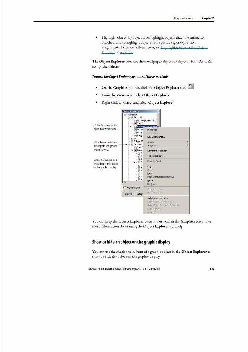
8/17/2019 FactoryTalk® View Machine Edition User's Guide
http://slidepdf.com/reader/full/factorytalk-view-machine-edition-users-guide 359/587
Use graphic objects Chapter 20
Rockwell Automation Publication - VIEWME-UM004L-EN-E – March 2016 359
• Highlight objects by object type, highlight objects that have animationattached, and to highlight objects with specific tag or expressionassignments. For more information, see Highlight objects in the ObjectExplorer on page 360.
The Object Explorer does not show wallpaper objects or objects within ActiveXcomposite objects.
To open the Object Explorer, use one of these methods
• On the Graphics toolbar, click the Object Explorer tool .
• From the View menu, select Object Explorer .
• Right-click an object and select Object Explorer .
You can keep the Object Explorer open as you work in the Graphics editor. Formore information about using the Object Explorer , see Help.
Show or hide an object on the graphic display
You can use the check box in front of a graphic object in the Object Explorer toshow or hide the object on the graphic display.

8/17/2019 FactoryTalk® View Machine Edition User's Guide
http://slidepdf.com/reader/full/factorytalk-view-machine-edition-users-guide 360/587
Chapter 20 Use graphic objects
360 Rockwell Automation Publication - VIEWME-UM004L-EN-E – March 2016
To show or hide an object on the graphic display
• In the Object Explorer , select the check box in front of the object you wantto show, or clear the check box in front of the object you want to hide.
Tip: • By default, all check boxes in the Object Explorer are selected and all objectsare shown on the graphic display.
• If you select or clear the check box in front of a group in the Object Explorer,all objects in the group are shown or hidden on the graphic display. If you selector clear the check box in front of the root node, Display in the Object
Explorer, all the objects on the graphic display are shown or hidden.
• At runtime, the visibility state of a graphic object depends on the expression.The Object Explorer visibility state of a graphic object has no effect on thedefault visibility state of the object at runtime.
Highlight objects in the Object Explorer
You can use the Object Explorer to highlight:
• Specific types of objects
• Objects that have animation attached
• Objects that have a specific tag or expression assigned to them
The objects are highlighted in red in the Object Explorer and in the graphicdisplay. If your graphic display uses a red background, the highlighting is not visible in the graphic display.
To highlight objects in the Object Explorer
1. In the Object Explorer , select the Highlighting on check box, and thenclick Settings.
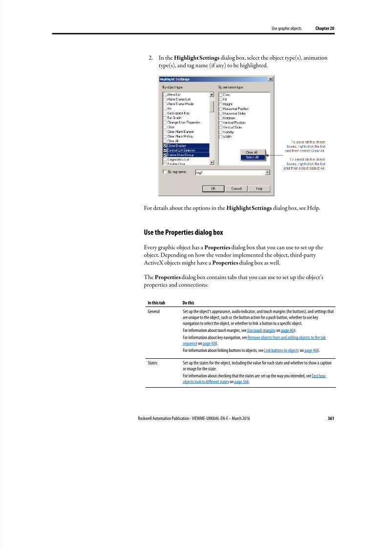
8/17/2019 FactoryTalk® View Machine Edition User's Guide
http://slidepdf.com/reader/full/factorytalk-view-machine-edition-users-guide 361/587
Use graphic objects Chapter 20
Rockwell Automation Publication - VIEWME-UM004L-EN-E – March 2016 361
2. In the Highlight Settings dialog box, select the object type(s), animationtype(s), and tag name (if any) to be highlighted.
For details about the options in the Highlight Settings dialog box, see Help.
Use the Properties dialog box
Every graphic object has a Properties dialog box that you can use to set up the
object. Depending on how the vendor implemented the object, third-partyActiveX objects might have a Properties dialog box as well.
The Properties dialog box contains tabs that you can use to set up the object’s properties and connections:
In this tab Do this
General Set up the object’s appearance, audio indicator, and touch margins (for buttons), and settings thatare unique to the object, such as the button action for a push button, whether to use keynavigation to select the object, or whether to link a button to a specific object.
For information about touch margins, see Use touch margins on page 404.
For information about key navigation, see Remove objects from and adding objects to the tabsequence on page 408.
For information about linking buttons to objects, see Link buttons to objects on page 408.
States Set up the states for the object, including the value for each state and whether to show a captionor image for the state.
For information about checking that the states are set up the way you intended, see Test howobjects look in different states on page 368.
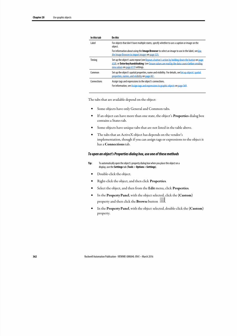
8/17/2019 FactoryTalk® View Machine Edition User's Guide
http://slidepdf.com/reader/full/factorytalk-view-machine-edition-users-guide 362/587
Chapter 20 Use graphic objects
362 Rockwell Automation Publication - VIEWME-UM004L-EN-E – March 2016
In this tab Do this
Label For objects that don’t have multiple states, specify whether to use a caption or image on theobject.
For information about using the Image Browser to select an image to use in the label, see Usethe Image Browser to import images on page 325.
Timing Set up the object’s auto repeat (see Repeat a button’s action by holding down the button on page410), or Enter key handshaking (see Ensure values are read by the data s ource before sendingnew values on page 411) settings.
Common Set up the object’s spatial properties, name and visibility. For details, see Set up objects’ spatialproperties, names, and visibility on page 401.
Connections Assign tags and expressions to the object’s connections.
For information, see Assign tags and expressions to graphic objects on page 369.
The tabs that are available depend on the object:
• Some objects have only General and Common tabs.
• If an object can have more than one state, the object’s Properties dialog boxcontains a States tab.
• Some objects have unique tabs that are not listed in the table above.
• The tabs that an ActiveX object has depends on the vendor’simplementation, though if you can assign tags or expressions to the object ithas a Connections tab.
To open an object’s Properties dialog box, use one of these methods
Tip: To automatically open the object's property dialog box when you place the object on adisplay, use the Settings tab (Tools > Options >Settings).
• Double-click the object.
• Right-click the object, and then click Properties.
• Select the object, and then from the Edit menu, click Properties.
• In the Property Panel, with the object selected, click the (Custom)
property and then click the Browse button .
•
In the Property Panel, with the object selected, double-click the (Custom) property.
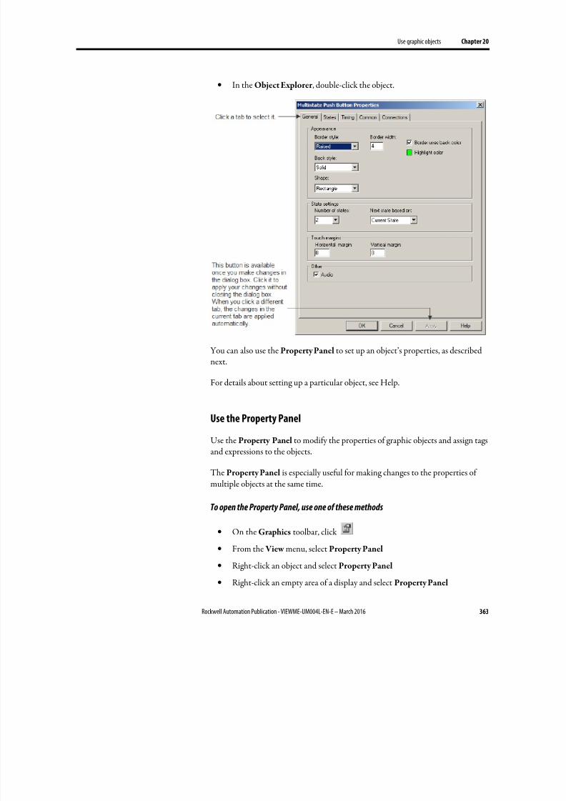
8/17/2019 FactoryTalk® View Machine Edition User's Guide
http://slidepdf.com/reader/full/factorytalk-view-machine-edition-users-guide 363/587
Use graphic objects Chapter 20
Rockwell Automation Publication - VIEWME-UM004L-EN-E – March 2016 363
• In the Object Explorer , double-click the object.
You can also use the Property Panel to set up an object’s properties, as describednext.
For details about setting up a particular object, see Help.
Use the Property Panel
Use the Property Panel to modify the properties of graphic objects and assign tagsand expressions to the objects.
The Property Panel is especially useful for making changes to the properties ofmultiple objects at the same time.
To open the Property Panel, use one of these methods
• On the Graphics toolbar, click
• From the View menu, select Property Panel
• Right-click an object and select Property Panel
• Right-click an empty area of a display and select Property Panel
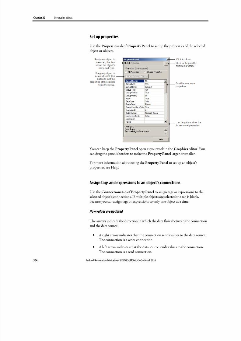
8/17/2019 FactoryTalk® View Machine Edition User's Guide
http://slidepdf.com/reader/full/factorytalk-view-machine-edition-users-guide 364/587
Chapter 20 Use graphic objects
364 Rockwell Automation Publication - VIEWME-UM004L-EN-E – March 2016
Set up properties
Use the Properties tab of Property Panel to set up the properties of the selected
object or objects.
You can keep the Property Panel open as you work in the Graphics editor. Youcan drag the panel’s borders to make the Property Panel larger or smaller.
For more information about using the Property Panel to set up an object’s properties, see Help.
Assign tags and expressions to an object’s connections
Use the Connections tab of Property Panel to assign tags or expressions to theselected object’s connections. If multiple objects are selected the tab is blank,because you can assign tags or expressions to only one object at a time.
How values are updated
The arrows indicate the direction in which the data flows between the connectionand the data source:
• A right arrow indicates that the connection sends values to the data source.The connection is a write connection.
• A left arrow indicates that the data source sends values to the connection.The connection is a read connection.
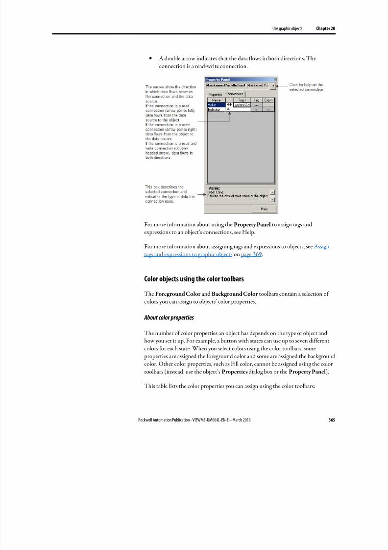
8/17/2019 FactoryTalk® View Machine Edition User's Guide
http://slidepdf.com/reader/full/factorytalk-view-machine-edition-users-guide 365/587
Use graphic objects Chapter 20
Rockwell Automation Publication - VIEWME-UM004L-EN-E – March 2016 365
• A double arrow indicates that the data flows in both directions. Theconnection is a read-write connection.
For more information about using the Property Panel to assign tags andexpressions to an object’s connections, see Help.
For more information about assigning tags and expressions to objects, see Assign
tags and expressions to graphic objects on page 369.
Color objects using the color toolbars
The Foreground Color and Background Color toolbars contain a selection ofcolors you can assign to objects’ color properties.
About color properties
The number of color properties an object has depends on the type of object and
how you set it up. For example, a button with states can use up to seven differentcolors for each state. When you select colors using the color toolbars, some properties are assigned the foreground color and some are assigned the backgroundcolor. Other color properties, such as Fill color, cannot be assigned using the colortoolbars (instead, use the object’s Properties dialog box or the Property Panel).
This table lists the color properties you can assign using the color toolbars:
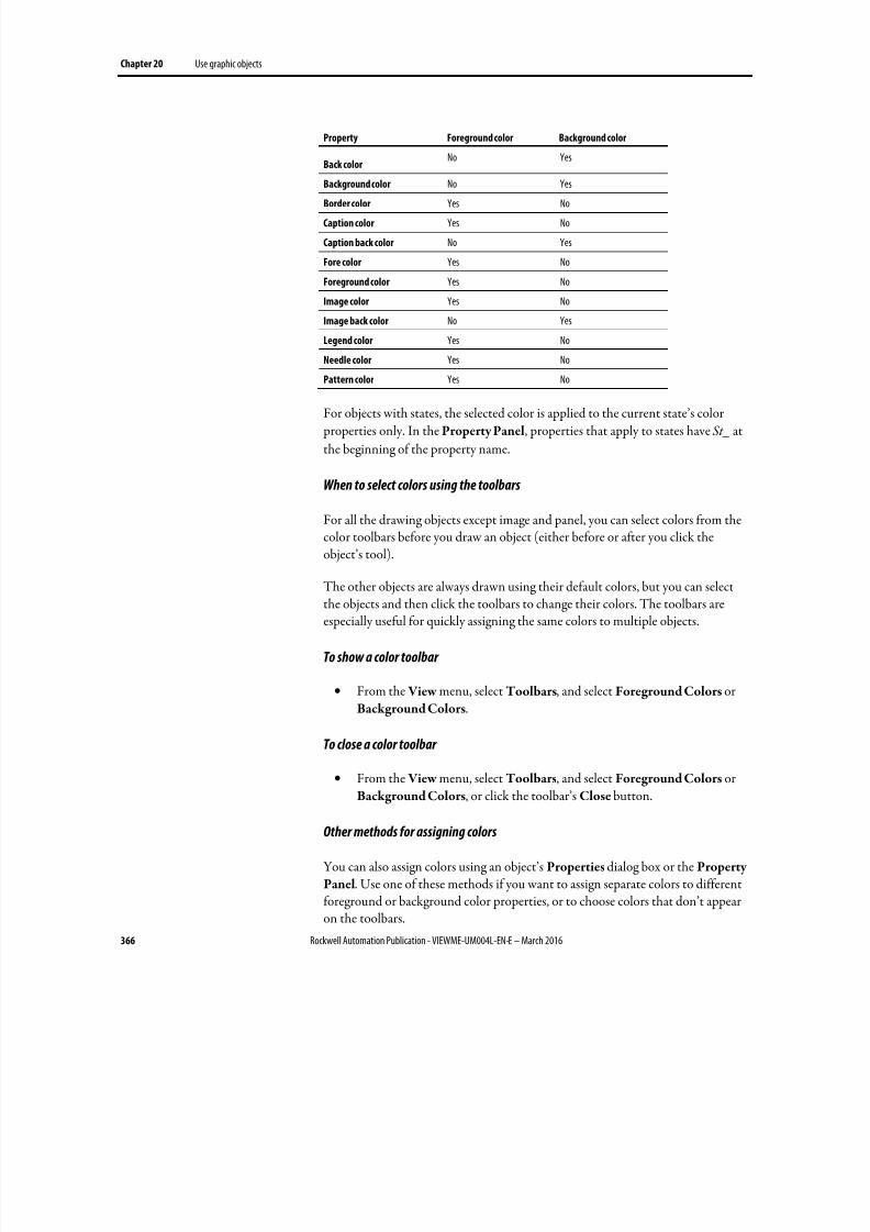
8/17/2019 FactoryTalk® View Machine Edition User's Guide
http://slidepdf.com/reader/full/factorytalk-view-machine-edition-users-guide 366/587
Chapter 20 Use graphic objects
366 Rockwell Automation Publication - VIEWME-UM004L-EN-E – March 2016
Property Foreground color Background color
Back colorNo Yes
Background color No Yes
Border color Yes No
Caption color Yes No
Caption back color No Yes
Fore color Yes No
Foreground color Yes No
Image color Yes No
Image back color No Yes
Legend color Yes No
Needle color Yes No
Pattern color Yes No
For objects with states, the selected color is applied to the current state’s color properties only. In the Property Panel, properties that apply to states have St_ at
the beginning of the property name.
When to select colors using the toolbars
For all the drawing objects except image and panel, you can select colors from thecolor toolbars before you draw an object (either before or after you click theobject’s tool).
The other objects are always drawn using their default colors, but you can selectthe objects and then click the toolbars to change their colors. The toolbars areespecially useful for quickly assigning the same colors to multiple objects.
To show a color toolbar
• From the View menu, select Toolbars, and select Foreground Colors orBackground Colors.
To close a color toolbar
• From the View menu, select Toolbars, and select Foreground Colors orBackground Colors, or click the toolbar’s Close button.
Other methods for assigning colors
You can also assign colors using an object’s Properties dialog box or the Property
Panel. Use one of these methods if you want to assign separate colors to differentforeground or background color properties, or to choose colors that don’t appearon the toolbars.
8/17/2019 FactoryTalk® View Machine Edition User's Guide
http://slidepdf.com/reader/full/factorytalk-view-machine-edition-users-guide 367/587
Use graphic objects Chapter 20
Rockwell Automation Publication - VIEWME-UM004L-EN-E – March 2016 367
For example, if you want to use a dark blue background color for a button, with alight blue background color for its image label, you must assign the colorsseparately. Using the toolbar would assign the same color to both properties.
Also use the Properties dialog box or Property Panel to change the default colorsfor properties that cannot be assigned using the color toolbars.
Name objects
Objects (and groups of objects) are automatically given a name and number when you create them, for example NumericInputEnable4. If desired, you can assign amore meaningful name to the object, for example Conveyor_speed_input. Eachobject in a display must have a unique name.
The object name appears in the status bar, Diagnostics List, Property Panel, andObject Explorer in FactoryTalk View Studio, and in diagnostics log messages atruntime.
To name an object in the Property Panel
1. Select the object.
2. In the Property Panel, click the Properties tab.
3. Double-click the (Name) row, and then type the name.
The name must start with a letter, and cannot contain spaces. You can use
the underscore character (_).
To name an object in its Properties dialog box
1. Double-click the object to open its Properties dialog box.
2.
Click the Common tab.
3. In the Name box, type the name.
The name must start with a letter, and cannot contain spaces. You can use
the underscore character (_).
To name a group object
1. Select the group object.
2. In the Property Panel, click the Properties tab.
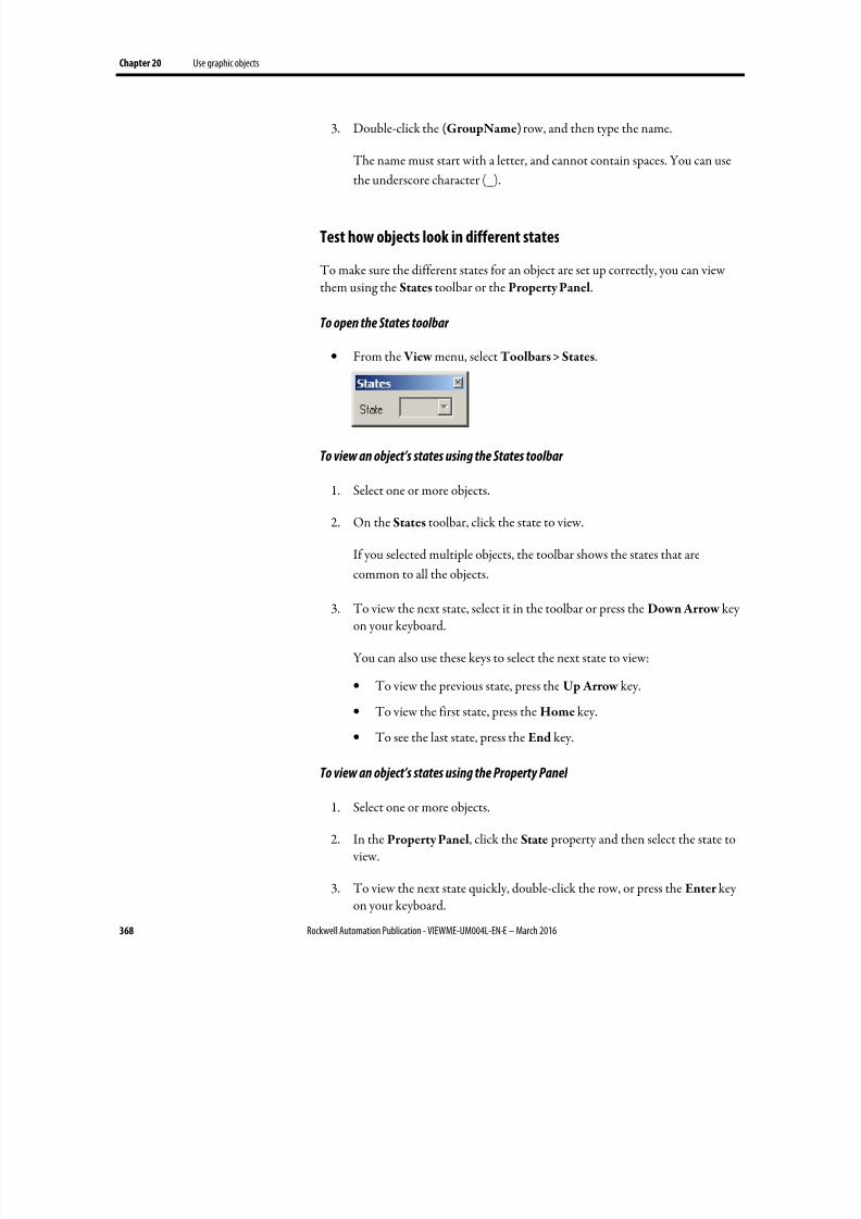
8/17/2019 FactoryTalk® View Machine Edition User's Guide
http://slidepdf.com/reader/full/factorytalk-view-machine-edition-users-guide 368/587
Chapter 20 Use graphic objects
368 Rockwell Automation Publication - VIEWME-UM004L-EN-E – March 2016
3. Double-click the (GroupName) row, and then type the name.
The name must start with a letter, and cannot contain spaces. You can use
the underscore character (_).
Test how objects look in different states
To make sure the different states for an object are set up correctly, you can viewthem using the States toolbar or the Property Panel.
To open the States toolbar
• From the View menu, select Toolbars > States.
To view an object’s states using the States toolbar
1. Select one or more objects.
2. On the States toolbar, click the state to view.
If you selected multiple objects, the toolbar shows the states that are
common to all the objects.
3. To view the next state, select it in the toolbar or press the Down Arrow keyon your keyboard.
You can also use these keys to select the next state to view:
• To view the previous state, press the Up Arrow key.
• To view the first state, press the Home key.
• To see the last state, press the End key.
To view an object’s states using the Property Panel
1. Select one or more objects.
2.
In the Property Panel, click the State property and then select the state to view.
3. To view the next state quickly, double-click the row, or press the Enter keyon your keyboard.
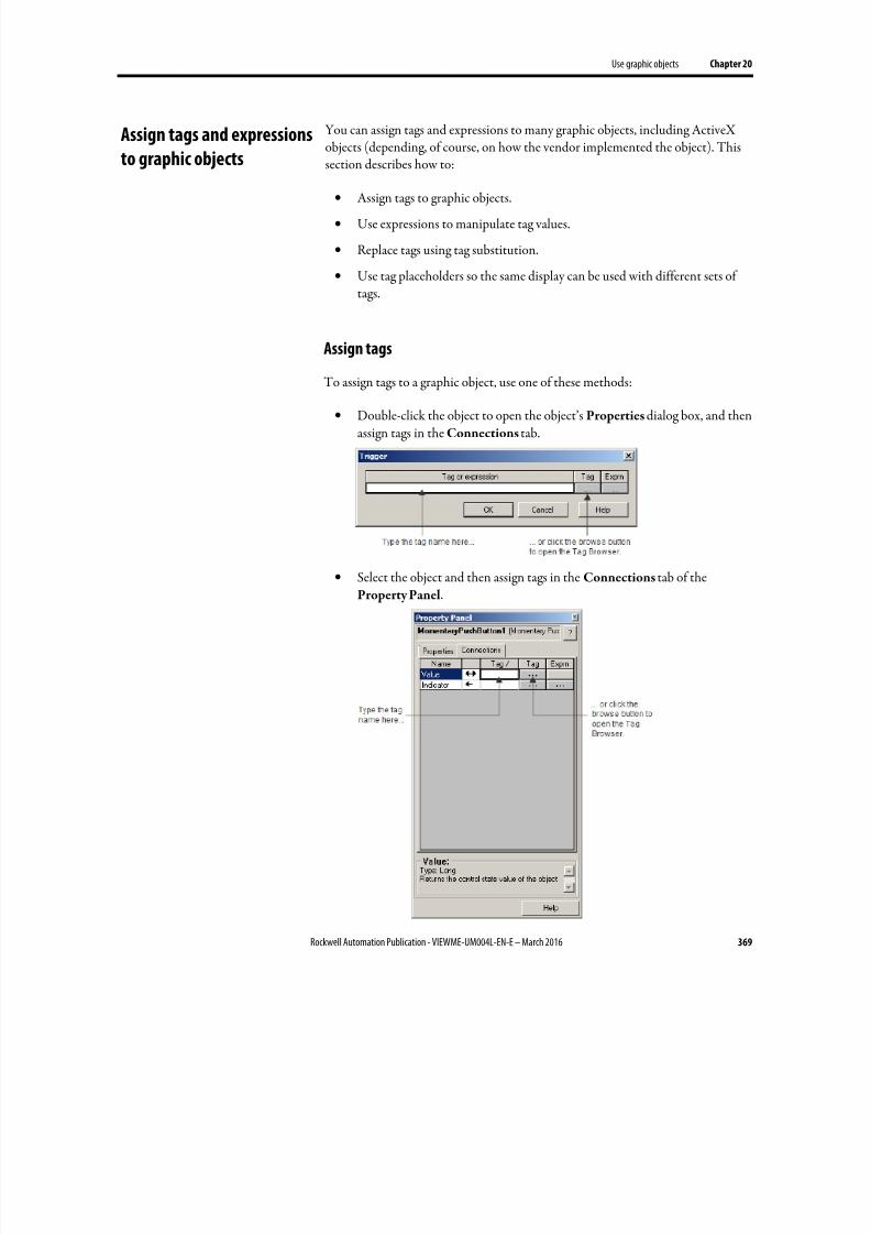
8/17/2019 FactoryTalk® View Machine Edition User's Guide
http://slidepdf.com/reader/full/factorytalk-view-machine-edition-users-guide 369/587
Use graphic objects Chapter 20
Rockwell Automation Publication - VIEWME-UM004L-EN-E – March 2016 369
You can assign tags and expressions to many graphic objects, including ActiveXobjects (depending, of course, on how the vendor implemented the object). Thissection describes how to:
•
Assign tags to graphic objects.
• Use expressions to manipulate tag values.
• Replace tags using tag substitution.
• Use tag placeholders so the same display can be used with different sets oftags.
Assign tags
To assign tags to a graphic object, use one of these methods:
• Double-click the object to open the object’s Properties dialog box, and thenassign tags in the Connections tab.
•
Select the object and then assign tags in the Connections tab of theProperty Panel.
Assign tags and expressions
to graphic objects
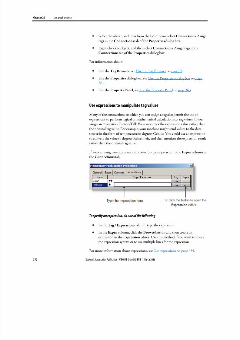
8/17/2019 FactoryTalk® View Machine Edition User's Guide
http://slidepdf.com/reader/full/factorytalk-view-machine-edition-users-guide 370/587
Chapter 20 Use graphic objects
370 Rockwell Automation Publication - VIEWME-UM004L-EN-E – March 2016
• Select the object, and then from the Edit menu, select Connections. Assigntags in the Connections tab of the Properties dialog box.
• Right-click the object, and then select Connections. Assign tags in the
Connections tab of the Properties dialog box.
For information about:
• Use the Tag Browser , see Use the Tag Browser on page 92.
• Use the Properties dialog box, see Use the Properties dialog box on page361.
• Use the Property Panel, see Use the Property Panel on page 363.
Use expressions to manipulate tag values
Many of the connections to which you can assign a tag also permit the use ofexpressions to perform logical or mathematical calculations on tag values. If youassign an expression, FactoryTalk View monitors the expression value rather thanthe original tag value. For example, your machine might send values to the datasource in the form of temperature in degrees Celsius. You could use an expressionto convert the value to degrees Fahrenheit, and then monitor the expression resultrather than the original tag value.
If you can assign an expression, a Browse button is present in the Exprn column in
the Connections tab.
To specify an expression, do one of the following
• In the Tag / Expression column, type the expression.
• In the Exprn column, click the Browse button and then create anexpression in the Expression editor. Use this method if you want to checkthe expression syntax, or to use multiple lines for the expression.
For more information about expressions, see Use expressions on page 435.
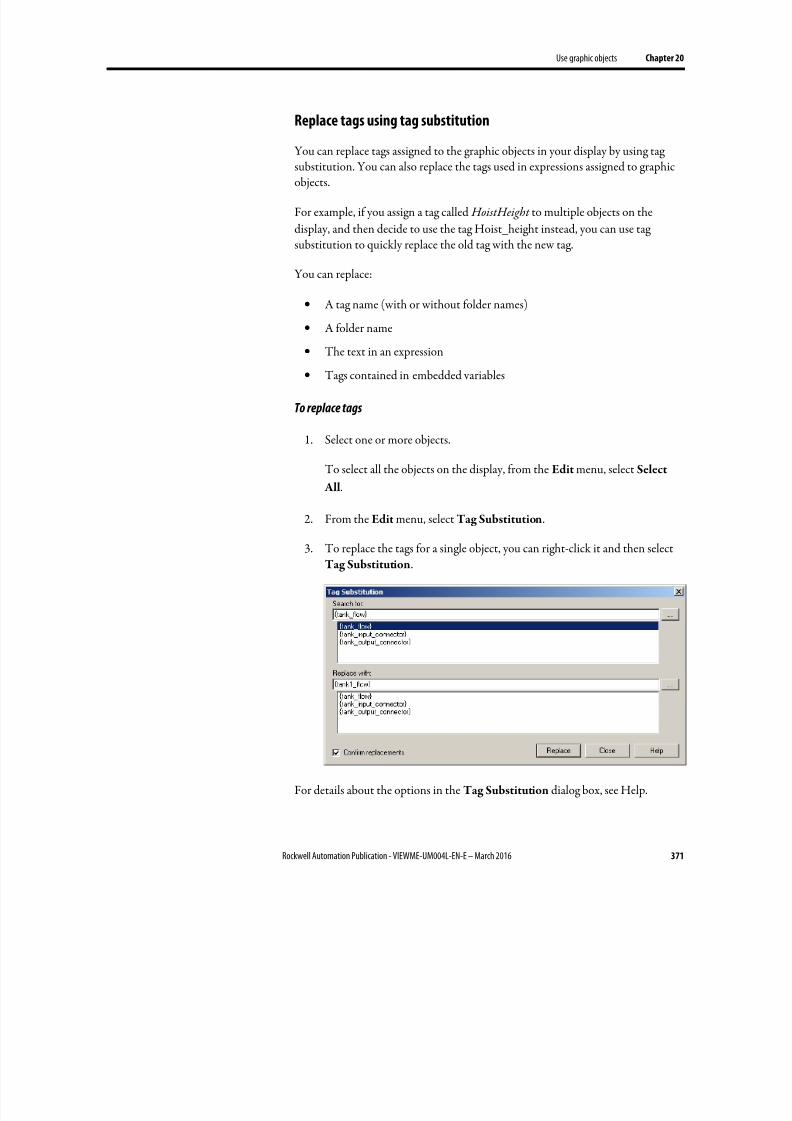
8/17/2019 FactoryTalk® View Machine Edition User's Guide
http://slidepdf.com/reader/full/factorytalk-view-machine-edition-users-guide 371/587
Use graphic objects Chapter 20
Rockwell Automation Publication - VIEWME-UM004L-EN-E – March 2016 371
Replace tags using tag substitution
You can replace tags assigned to the graphic objects in your display by using tag
substitution. You can also replace the tags used in expressions assigned to graphicobjects.
For example, if you assign a tag called HoistHeight to multiple objects on the
display, and then decide to use the tag Hoist_height instead, you can use tagsubstitution to quickly replace the old tag with the new tag.
You can replace:
• A tag name (with or without folder names)
• A folder name
•
The text in an expression
• Tags contained in embedded variables
To replace tags
1. Select one or more objects.
To select all the objects on the display, from the Edit menu, select Select
All.
2.
From the Edit menu, select Tag Substitution.
3.
To replace the tags for a single object, you can right-click it and then selectTag Substitution.
For details about the options in the Tag Substitution dialog box, see Help.

8/17/2019 FactoryTalk® View Machine Edition User's Guide
http://slidepdf.com/reader/full/factorytalk-view-machine-edition-users-guide 372/587
Chapter 20 Use graphic objects
372 Rockwell Automation Publication - VIEWME-UM004L-EN-E – March 2016
A log file is shown after substitution. It provides details on the substitution processand results. If the substitution fails, the reason will be shown. The last line shows where the log file is located in case you want to review it in the future.
Replace tags using Find and Replace
You can replace tags or components that refer to tags using Find and Replace, afunction that has been added with version 7.00.00.
To replace tags
1. Open the Find and Replace dialog box by doing one of the following:
•
On the toolbar, click• From the Tools menu, select Replace
• Press Ctrl+H.
2.
Click the browse button ( ) next to Find what, which launches the TagBrowser .
• Navigate to the correct folder in the left pane, and then select the tag inthe right pane.
• Click OK to save the selection and close the browser.
3. Click the browse button next to Replace with. Select the replacement tagfrom the Tag Browser and click OK to save the selection and close thebrowser.
4.
Click on the browse button next to Find within and clear all the checkboxes except Graphic Objects. Click OK to save the selection and close thedialog box.
5. Identify the word search limitations in Find Options.
6.
Select the Direction, in which to search:
• Select Up to search for the tag or text string in all components beforethe shown one.
• Select Down to search for the tag or text string in all components afterthe shown one.
7. To replace items, select Confirm replacement if needed, then:
8/17/2019 FactoryTalk® View Machine Edition User's Guide
http://slidepdf.com/reader/full/factorytalk-view-machine-edition-users-guide 373/587
Use graphic objects Chapter 20
Rockwell Automation Publication - VIEWME-UM004L-EN-E – March 2016 373
• To select individual items to replace, click Find Next and then clickReplace, when the correct item is shown or
• To replace all tags, Click Replace All to replace all found items.
If needed, click the View Log File button to show a text file of the results of theReplace, Replace All or Undo Replace functions.
To undo replacements, click Undo Replace. Only the last replace or replace allaction can be undone. Undo will not be successful if a component has beenmanually edited after the replace action.
Use tag placeholders
Tag placeholders provide a way to use one graphic display to represent a number ofsimilar operations.
For example, suppose you are creating displays for a plant that cans corn and peas.The machinery used in both processes is identical. Instead of creating two displaysand specifying corn-related tags in one display and pea-related tags in another, youcan create one display and not specify any tag names. Where a tag name isrequired, type a tag placeholder.
You can use tag placeholders wherever you would normally assign a tag to anobject, including in expressions and embedded variables. You can also use tag placeholders in the expressions you create to animate objects.
You can also use tag placeholders with global objects.
You can use tag placeholders in:
• The graphic display that opens when the application is first run.
• Graphic displays that are opened using a Goto display button.
• Graphic displays that are opened using a display list selector.
• The graphic display that opens when the logout button is pressed to log the
logged-on user out.• The graphic display specified in the Project Settings Runtime tab when
auto logout is enabled.
• Graphic displays that are opened using the Remote Display Number globalconnection.
Use parameter files or parameter lists to specify which tags or folders to substitutefor which placeholders. For global objects, you can specify the tags or folders oftags using global object parameters.
8/17/2019 FactoryTalk® View Machine Edition User's Guide
http://slidepdf.com/reader/full/factorytalk-view-machine-edition-users-guide 374/587
Chapter 20 Use graphic objects
374 Rockwell Automation Publication - VIEWME-UM004L-EN-E – March 2016
For more information about using parameter files, parameter lists, and globalobject parameters, see Use parameters and global objects on page 461.
Create tag placeholders
A tag placeholder is the cross-hatch character (#) followed by a number from 1 to500.
The tag placeholder can replace any part of a tag name, including folder names.For example, you could create a parameter file specifying that the tag placeholder#1=Folder1. You could assign the folder and a tag name to a graphic object’sconnection: #1\Tag1.
You can assign tag placeholders in:
•
The Connections tab of an object’s Properties dialog box.
• The Connections tab of the Property Panel.
• The Expression box in the Animation dialog box.
• Anywhere that you can insert an embedded variable. For information aboutembedded variables, see Use embedded variables on page 453.
To create a tag placeholder
• Type the cross-hatch character followed by a number (no space in between).
For example, #1.
Once you have drawn an object, you can select the object and work with it. Youcan:
• Move objects
• Copy objects
• Duplicate objects
• Resize objects
• Reshape drawing objects
• Delete objects
Move objects
You can move objects using the mouse or the keyboard. The keys give you fine positioning, allowing you to move objects in small increments. You can also usethe grid to position objects precisely.
Perform basic operations on
objects
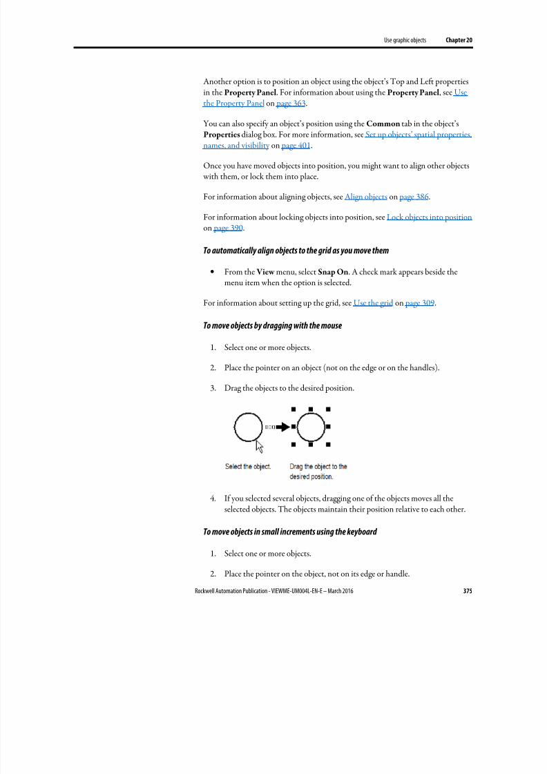
8/17/2019 FactoryTalk® View Machine Edition User's Guide
http://slidepdf.com/reader/full/factorytalk-view-machine-edition-users-guide 375/587
Use graphic objects Chapter 20
Rockwell Automation Publication - VIEWME-UM004L-EN-E – March 2016 375
Another option is to position an object using the object’s Top and Left propertiesin the Property Panel. For information about using the Property Panel, see Usethe Property Panel on page 363.
You can also specify an object’s position using the Common tab in the object’sProperties dialog box. For more information, see Set up objects’ spatial properties,names, and visibility on page 401.
Once you have moved objects into position, you might want to align other objects with them, or lock them into place.
For information about aligning objects, see Align objects on page 386.
For information about locking objects into position, see Lock objects into position on page 390.
To automatically align objects to the grid as you move them
• From the View menu, select Snap On. A check mark appears beside themenu item when the option is selected.
For information about setting up the grid, see Use the grid on page 309.
To move objects by dragging with the mouse
1. Select one or more objects.
2. Place the pointer on an object (not on the edge or on the handles).
3. Drag the objects to the desired position.
4. If you selected several objects, dragging one of the objects moves all theselected objects. The objects maintain their position relative to each other.
To move objects in small increments using the keyboard
1. Select one or more objects.
2. Place the pointer on the object, not on its edge or handle.
8/17/2019 FactoryTalk® View Machine Edition User's Guide
http://slidepdf.com/reader/full/factorytalk-view-machine-edition-users-guide 376/587
8/17/2019 FactoryTalk® View Machine Edition User's Guide
http://slidepdf.com/reader/full/factorytalk-view-machine-edition-users-guide 377/587
Use graphic objects Chapter 20
Rockwell Automation Publication - VIEWME-UM004L-EN-E – March 2016 377
When you press Ctrl, a plus sign is added to the cursor.
3. When the object is where you want it, release the mouse button and thenthe Ctrl key.
A new copy of the object is created.
If you selected several objects, dragging one of the objects copies all the
selected objects. The objects maintain their position relative to each other.
To drag objects between displays
1. Open both displays (or a graphic library and a display).
2. Position or resize the displays so both are visible.
For more information, see Resize displays on page 314.
3. Select one or more objects.
4. Click the selected object and drag it to the new display.
If you selected several objects, dragging one of the objects copies all the
selected objects. The objects maintain their position relative to each other.
Copy and paste objects
You can cut, copy, or paste objects using the menu items on the Edit menu or thebuttons on the toolbar.
Once you cut or copy an object, you can paste it anywhere in the drawing area of:
• The same graphic display.
• A graphic display in the same or a different application.
• A graphic library in the same or a different application.
To cut or copy objects
1. Select one or more objects.
2.
From the Edit menu, select Cut or Copy , or click or on theGraphics toolbar.
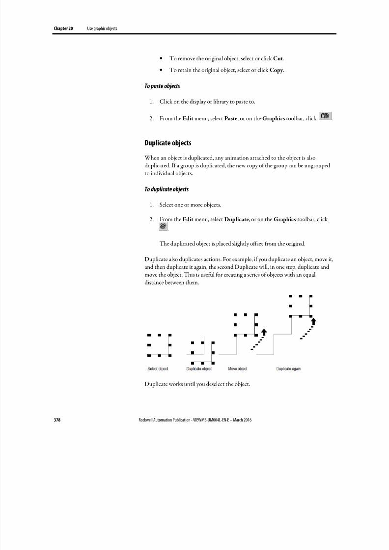
8/17/2019 FactoryTalk® View Machine Edition User's Guide
http://slidepdf.com/reader/full/factorytalk-view-machine-edition-users-guide 378/587
Chapter 20 Use graphic objects
378 Rockwell Automation Publication - VIEWME-UM004L-EN-E – March 2016
• To remove the original object, select or click Cut.
• To retain the original object, select or click Copy .
To paste objects
1.
Click on the display or library to paste to.
2. From the Edit menu, select Paste, or on the Graphics toolbar, click .
Duplicate objects
When an object is duplicated, any animation attached to the object is alsoduplicated. If a group is duplicated, the new copy of the group can be ungrouped
to individual objects.
To duplicate objects
1. Select one or more objects.
2. From the Edit menu, select Duplicate, or on the Graphics toolbar, click
.
The duplicated object is placed slightly offset from the original.
Duplicate also duplicates actions. For example, if you duplicate an object, move it,and then duplicate it again, the second Duplicate will, in one step, duplicate andmove the object. This is useful for creating a series of objects with an equaldistance between them.
Duplicate works until you deselect the object.
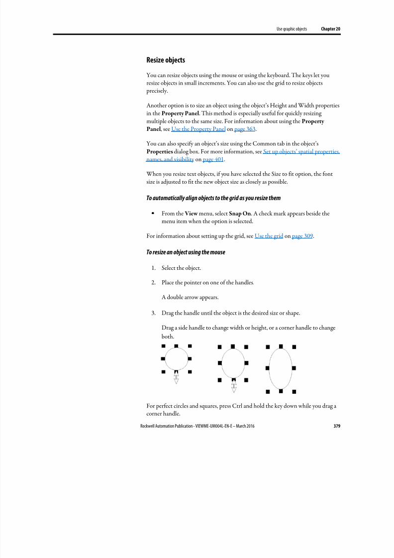
8/17/2019 FactoryTalk® View Machine Edition User's Guide
http://slidepdf.com/reader/full/factorytalk-view-machine-edition-users-guide 379/587
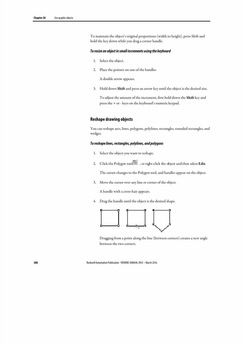
8/17/2019 FactoryTalk® View Machine Edition User's Guide
http://slidepdf.com/reader/full/factorytalk-view-machine-edition-users-guide 380/587
Chapter 20 Use graphic objects
380 Rockwell Automation Publication - VIEWME-UM004L-EN-E – March 2016
To maintain the object’s original proportions (width to height), press Shift andhold the key down while you drag a corner handle.
To resize an object in small increments using the keyboard
1. Select the object.
2. Place the pointer on one of the handles.
A double arrow appears.
3. Hold down Shift and press an arrow key until the object is the desired size.
To adjust the amount of the increment, first hold down the Shift key and
press the + or - keys on the keyboard’s numeric keypad.
Reshape drawing objects
You can reshape arcs, lines, polygons, polylines, rectangles, rounded rectangles, and wedges.
To reshape lines, rectangles, polylines, and polygons
1. Select the object you want to reshape.
2. Click the Polygon tool , or right-click the object and then select Edit.
The cursor changes to the Polygon tool, and handles appear on the object.
3. Move the cursor over any line or corner of the object.
A handle with a cross-hair appears.
4. Drag the handle until the object is the desired shape.
Dragging from a point along the line (between corners) creates a new angle
between the two corners.
8/17/2019 FactoryTalk® View Machine Edition User's Guide
http://slidepdf.com/reader/full/factorytalk-view-machine-edition-users-guide 381/587
Use graphic objects Chapter 20
Rockwell Automation Publication - VIEWME-UM004L-EN-E – March 2016 381
5. To delete an angle, position the pointer at the tip of the angle, and then press Delete.
To reshape arcs and wedges
1. Select the object you want to reshape.
2. Click the Arc tool , or the Wedge tool , or right-click the objectand then select Edit.
The cursor changes to the Arc or Wedge tool, and handles appear on the
object.
3. Place the pointer on one of the handles.
A cross-hair appears.
4. Drag the handle until the object is the desired shape.
To reshape rounded rectangles
1. Select the rounded rectangle.
2. Click the Rounded Rectangle tool , or right-click the object and thenselect Edit.
A handle appears inside the rounded rectangle.
3. Click the handle and drag inward to increase roundedness, or outward todecrease roundedness.
Delete objects
If you accidentally delete an object, use the Undo tool to restore it.
To delete objects
1. Select one or more objects.
2. From the Edit menu, select Delete, or press Delete on the keyboard.
To delete all the objects in the display
• From the Edit menu, select Clear All.
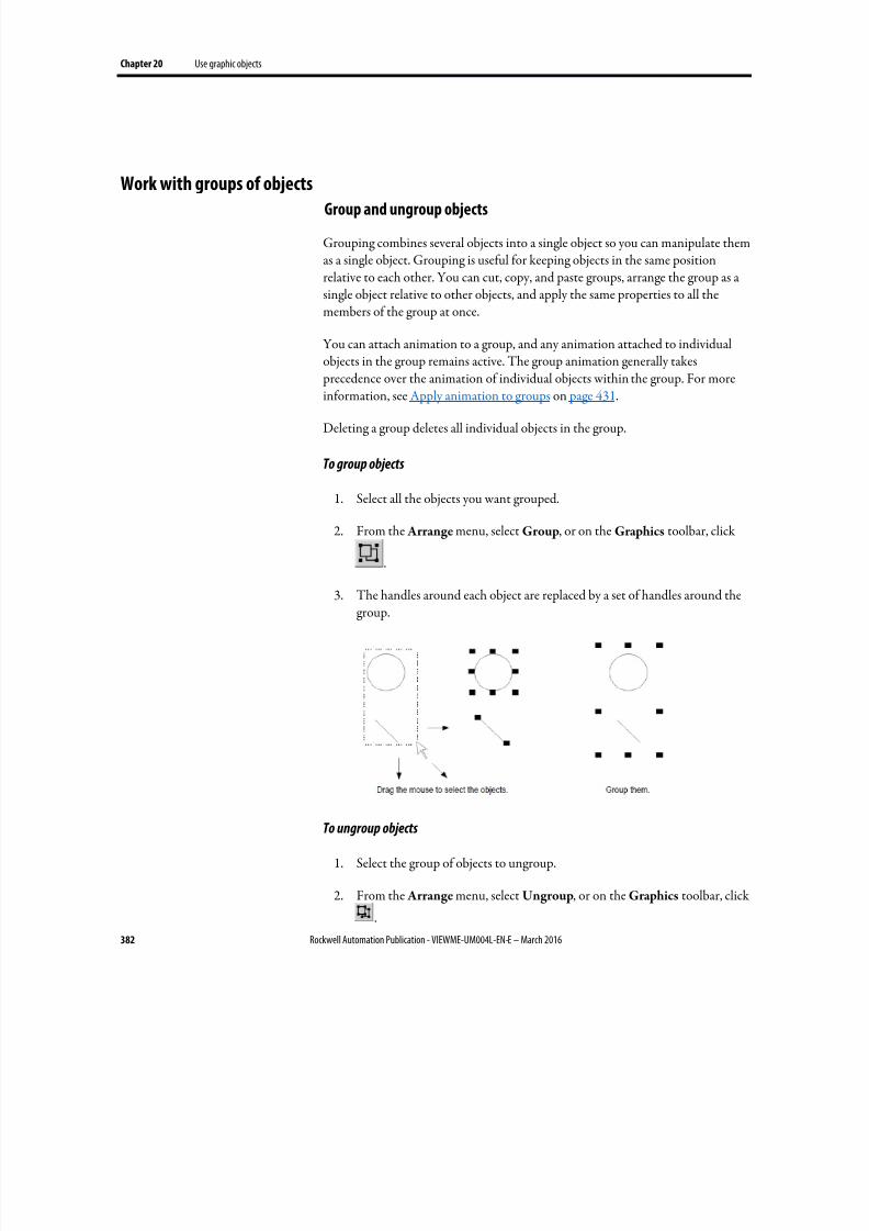
8/17/2019 FactoryTalk® View Machine Edition User's Guide
http://slidepdf.com/reader/full/factorytalk-view-machine-edition-users-guide 382/587
Chapter 20 Use graphic objects
382 Rockwell Automation Publication - VIEWME-UM004L-EN-E – March 2016
Group and ungroup objects
Grouping combines several objects into a single object so you can manipulate themas a single object. Grouping is useful for keeping objects in the same positionrelative to each other. You can cut, copy, and paste groups, arrange the group as asingle object relative to other objects, and apply the same properties to all themembers of the group at once.
You can attach animation to a group, and any animation attached to individualobjects in the group remains active. The group animation generally takes
precedence over the animation of individual objects within the group. For moreinformation, see Apply animation to groups on page 431.
Deleting a group deletes all individual objects in the group.
To group objects
1. Select all the objects you want grouped.
2. From the Arrange menu, select Group, or on the Graphics toolbar, click
.
3. The handles around each object are replaced by a set of handles around thegroup.
To ungroup objects
1. Select the group of objects to ungroup.
2. From the Arrange menu, select Ungroup, or on the Graphics toolbar, click
.
Work with groups of objects
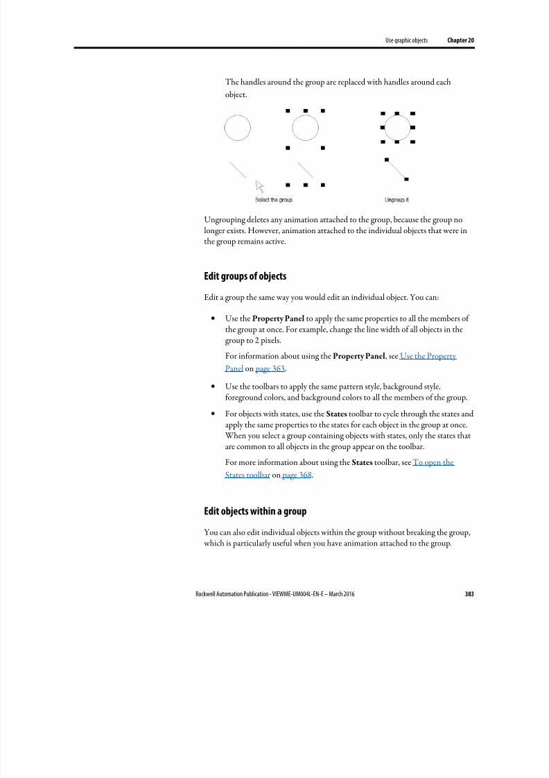
8/17/2019 FactoryTalk® View Machine Edition User's Guide
http://slidepdf.com/reader/full/factorytalk-view-machine-edition-users-guide 383/587
Use graphic objects Chapter 20
Rockwell Automation Publication - VIEWME-UM004L-EN-E – March 2016 383
The handles around the group are replaced with handles around each
object.
Ungrouping deletes any animation attached to the group, because the group nolonger exists. However, animation attached to the individual objects that were in
the group remains active.
Edit groups of objects
Edit a group the same way you would edit an individual object. You can:
• Use the Property Panel to apply the same properties to all the members ofthe group at once. For example, change the line width of all objects in thegroup to 2 pixels.
For information about using the Property Panel, see Use the Property
Panel on page 363.
• Use the toolbars to apply the same pattern style, background style,foreground colors, and background colors to all the members of the group.
• For objects with states, use the States toolbar to cycle through the states andapply the same properties to the states for each object in the group at once. When you select a group containing objects with states, only the states thatare common to all objects in the group appear on the toolbar.
For more information about using the States toolbar, see To open the
States toolbar on page 368.
Edit objects within a group
You can also edit individual objects within the group without breaking the group, which is particularly useful when you have animation attached to the group.

8/17/2019 FactoryTalk® View Machine Edition User's Guide
http://slidepdf.com/reader/full/factorytalk-view-machine-edition-users-guide 384/587
Chapter 20 Use graphic objects
384 Rockwell Automation Publication - VIEWME-UM004L-EN-E – March 2016
To edit objects within a group
1. Double-click the grouped object, or right-click it and then click Edit. Ahatched border appears around the group.
When the hatched border is around the group, you are in group edit mode.
In this mode, you can select individual objects in the group and modify
them.
You can also add new objects to the group.
2.
To select an individual object (or a group) in the group, click it. You canalso use the Object Explorer to select objects within the group.
The status bar and Object Explorer indicate which object or group is
selected.
3. Make your changes to the object.
You can change the selected object’s shape, size, or position, or use the
object’s Properties dialog box or the Property Panel to edit the object’s
properties.
4. If desired, create new objects inside the hatched border.
5. To stop editing, click outside the group.
You can arrange objects (or groups of objects) in a number of ways. You can:
• Layer objects by moving them in front of or behind other objects.
• Align objects with each other and with the grid.
• Space objects horizontally or vertically.
• Flip drawing objects horizontally or vertically.
• Rotate drawing objects.
• Lock objects into position.
Arrange objects
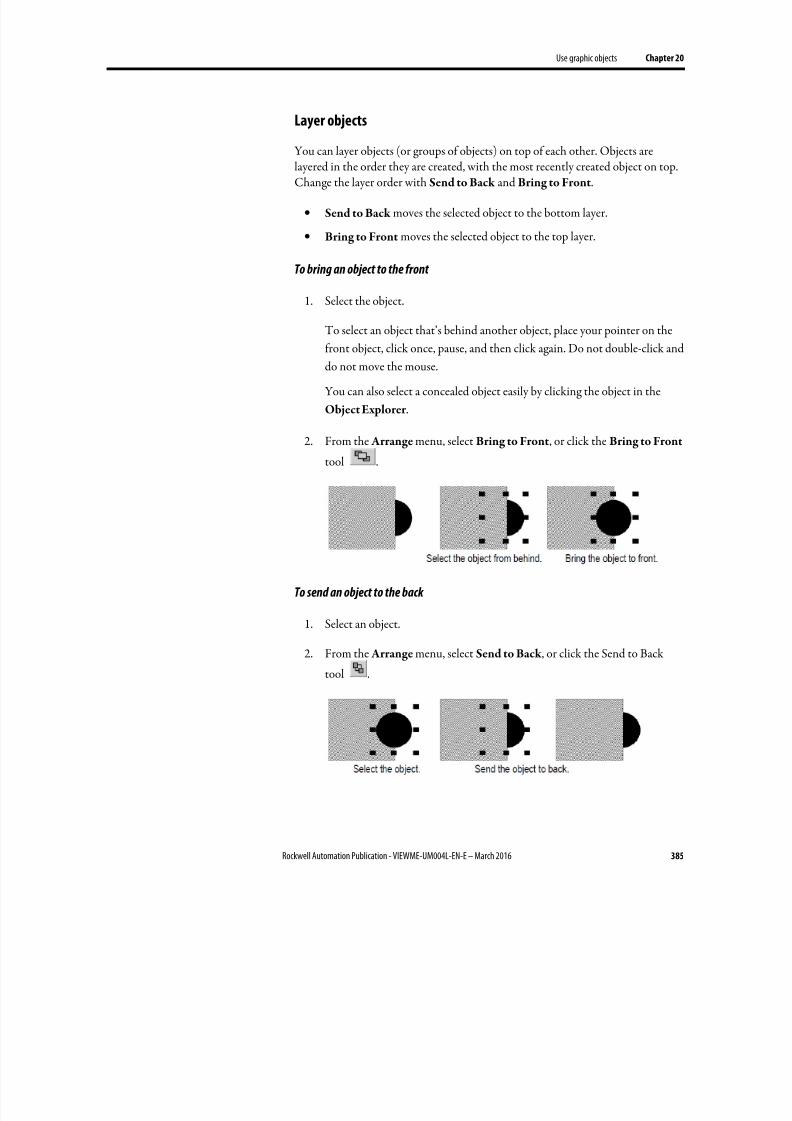
8/17/2019 FactoryTalk® View Machine Edition User's Guide
http://slidepdf.com/reader/full/factorytalk-view-machine-edition-users-guide 385/587
Use graphic objects Chapter 20
Rockwell Automation Publication - VIEWME-UM004L-EN-E – March 2016 385
Layer objects
You can layer objects (or groups of objects) on top of each other. Objects are
layered in the order they are created, with the most recently created object on top.Change the layer order with Send to Back and Bring to Front.
• Send to Back moves the selected object to the bottom layer.
• Bring to Front moves the selected object to the top layer.
To bring an object to the front
1. Select the object.
To select an object that’s behind another object, place your pointer on the
front object, click once, pause, and then click again. Do not double-click anddo not move the mouse.
You can also select a concealed object easily by clicking the object in the
Object Explorer .
2. From the Arrange menu, select Bring to Front, or click the Bring to Front
tool .
To send an object to the back
1.
Select an object.
2. From the Arrange menu, select Send to Back , or click the Send to Back
tool .
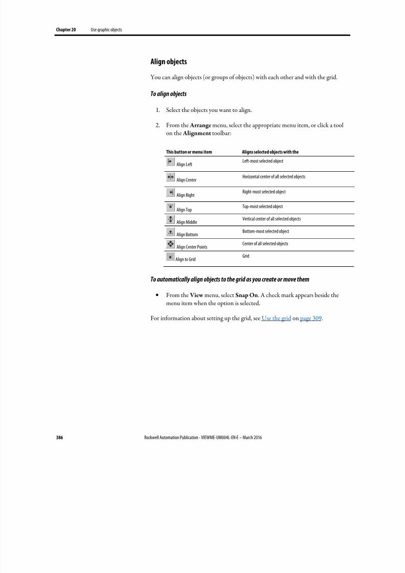
8/17/2019 FactoryTalk® View Machine Edition User's Guide
http://slidepdf.com/reader/full/factorytalk-view-machine-edition-users-guide 386/587
Chapter 20 Use graphic objects
386 Rockwell Automation Publication - VIEWME-UM004L-EN-E – March 2016
Align objects
You can align objects (or groups of objects) with each other and with the grid.
To align objects
1.
Select the objects you want to align.
2. From the Arrange menu, select the appropriate menu item, or click a toolon the Alignment toolbar:
This button or menu item Aligns selected objects with the
Align LeftLeft-most selected object
Align Center Horizontal center of all selected objects
Align RightRight-most selected object
Align TopTop-most selected object
Align MiddleVertical center of all selected objects
Align BottomBottom-most selected object
Align Center PointsCenter of all selected objects
Align to GridGrid
To automatically align objects to the grid as you create or move them
• From the View menu, select Snap On. A check mark appears beside themenu item when the option is selected.
For information about setting up the grid, see Use the grid on page 309.
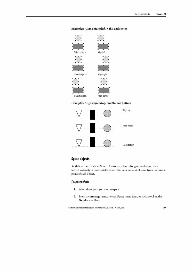
8/17/2019 FactoryTalk® View Machine Edition User's Guide
http://slidepdf.com/reader/full/factorytalk-view-machine-edition-users-guide 387/587
Use graphic objects Chapter 20
Rockwell Automation Publication - VIEWME-UM004L-EN-E – March 2016 387
Examples: Align objects left, right, and center
Examples: Align objects top, middle, and bottom
Space objects
With Space Vertical and Space Horizontal, objects (or groups of objects) are
moved vertically or horizontally to have the same amount of space from the center point of each object.
To space objects
1. Select the objects you want to space.
2. From the Arrange menu, select a Space menu item, or click a tool on theGraphics toolbar:
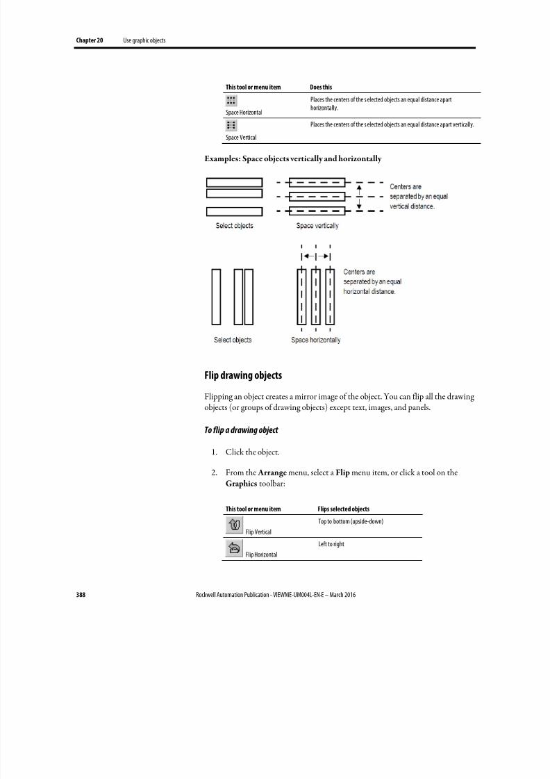
8/17/2019 FactoryTalk® View Machine Edition User's Guide
http://slidepdf.com/reader/full/factorytalk-view-machine-edition-users-guide 388/587
Chapter 20 Use graphic objects
388 Rockwell Automation Publication - VIEWME-UM004L-EN-E – March 2016
This tool or menu item Does this
Space Horizontal
Places the centers of the s elected objects an equal distance aparthorizontally.
Space Vertical
Places the centers of the s elected objects an equal distance apart vertically.
Examples: Space objects vertically and horizontally
Flip drawing objects
Flipping an object creates a mirror image of the object. You can flip all the drawingobjects (or groups of drawing objects) except text, images, and panels.
To flip a drawing object
1. Click the object.
2. From the Arrange menu, select a Flip menu item, or click a tool on the
Graphics toolbar:
This tool or menu item Flips selected objects
Flip Vertical
Top to bottom (upside-down)
Flip Horizontal
Left to right
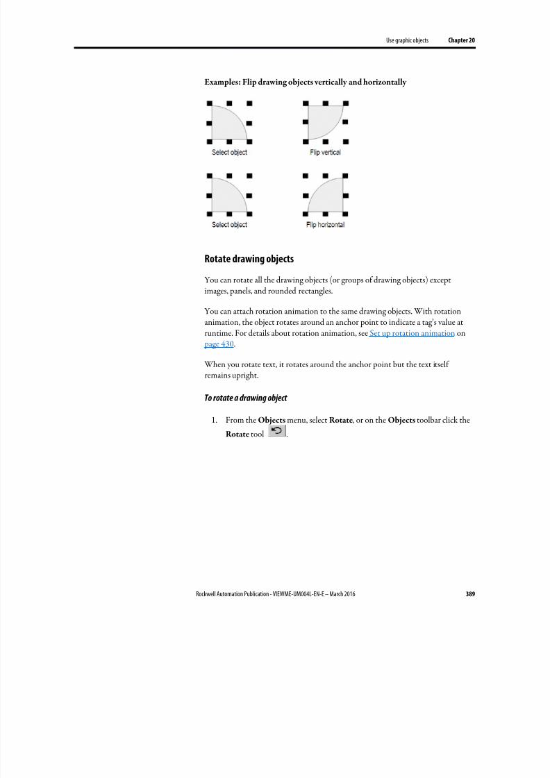
8/17/2019 FactoryTalk® View Machine Edition User's Guide
http://slidepdf.com/reader/full/factorytalk-view-machine-edition-users-guide 389/587
Use graphic objects Chapter 20
Rockwell Automation Publication - VIEWME-UM004L-EN-E – March 2016 389
Examples: Flip drawing objects vertically and horizontally
Rotate drawing objects
You can rotate all the drawing objects (or groups of drawing objects) exceptimages, panels, and rounded rectangles.
You can attach rotation animation to the same drawing objects. With rotationanimation, the object rotates around an anchor point to indicate a tag’s value atruntime. For details about rotation animation, see Set up rotation animation on page 430.
When you rotate text, it rotates around the anchor point but the text itselfremains upright.
To rotate a drawing object
1. From the Objects menu, select Rotate, or on the Objects toolbar click the
Rotate tool .
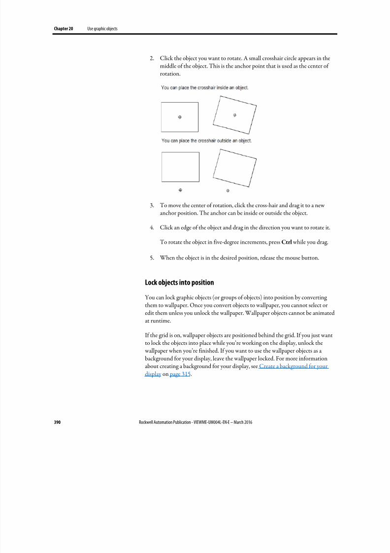
8/17/2019 FactoryTalk® View Machine Edition User's Guide
http://slidepdf.com/reader/full/factorytalk-view-machine-edition-users-guide 390/587
Chapter 20 Use graphic objects
390 Rockwell Automation Publication - VIEWME-UM004L-EN-E – March 2016
2. Click the object you want to rotate. A small crosshair circle appears in themiddle of the object. This is the anchor point that is used as the center ofrotation.
3. To move the center of rotation, click the cross-hair and drag it to a newanchor position. The anchor can be inside or outside the object.
4. Click an edge of the object and drag in the direction you want to rotate it.
To rotate the object in five-degree increments, press Ctrl while you drag.
5.
When the object is in the desired position, release the mouse button.
Lock objects into position
You can lock graphic objects (or groups of objects) into position by convertingthem to wallpaper. Once you convert objects to wallpaper, you cannot select oredit them unless you unlock the wallpaper. Wallpaper objects cannot be animatedat runtime.
If the grid is on, wallpaper objects are positioned behind the grid. If you just want
to lock the objects into place while you’re working on the display, unlock the wallpaper when you’re finished. If you want to use the wallpaper objects as abackground for your display, leave the wallpaper locked. For more informationabout creating a background for your display, see Create a background for yourdisplay on page 315.
8/17/2019 FactoryTalk® View Machine Edition User's Guide
http://slidepdf.com/reader/full/factorytalk-view-machine-edition-users-guide 391/587
Rockwell Automation Publication - VIEWME-UM004L-EN-E – March 2016 391
Chapter 21
Set up graphic objects
This chapter describes how to set up a graphic object, including:
• Set up a graphic object properties
• Set up how a graphic object is used at runtime
• Time, date, and number formats for a graphic object
To set up a graphic object
1. Double-click the graphic object.
2. In the Properties dialog box, specify the options on each tab. See Graphicobject properties on page 391.
3. When you are finished, click OK .
For information on how to set up each graphic object, see FactoryTalk ViewMachine Edition Help.
For information on how to use each graphic object, see Use graphic objects on page 335.
Graphic object properties
A graphic object may have several of the following tabs in the Properties dialogbox:
• General tab
•
Alarm Tab
• Display tab
• E-Signature tab
• States tab
• Label tab
• Print tab
• String tab
Set up a graphic object
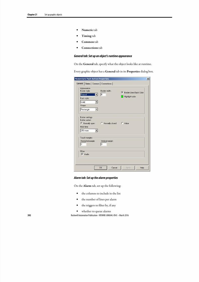
8/17/2019 FactoryTalk® View Machine Edition User's Guide
http://slidepdf.com/reader/full/factorytalk-view-machine-edition-users-guide 392/587
Chapter 21 Set up graphic objects
392 Rockwell Automation Publication - VIEWME-UM004L-EN-E – March 2016
• Numeric tab
• Timing tab
• Common tab
• Connections tab
General tab: Set up an object's runtime appearance
On the General tab, specify what the object looks like at runtime.
Every graphic object has a General tab in its Properties dialog box.
Alarm tab: Set up the alarm properties
On the Alarm tab, set up the following:
• the columns to include in the list
• the number of lines per alarm
• the triggers to filter by, if any
• whether to queue alarms
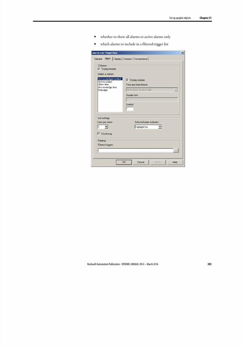
8/17/2019 FactoryTalk® View Machine Edition User's Guide
http://slidepdf.com/reader/full/factorytalk-view-machine-edition-users-guide 393/587
Set up graphic objects Chapter 21
Rockwell Automation Publication - VIEWME-UM004L-EN-E – March 2016 393
• whether to show all alarms or active alarms only
• which alarms to include in a filtered trigger list
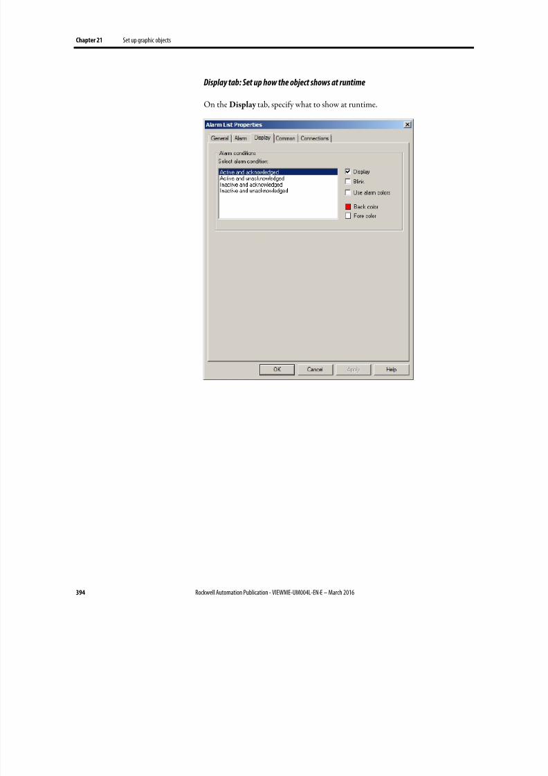
8/17/2019 FactoryTalk® View Machine Edition User's Guide
http://slidepdf.com/reader/full/factorytalk-view-machine-edition-users-guide 394/587
Chapter 21 Set up graphic objects
394 Rockwell Automation Publication - VIEWME-UM004L-EN-E – March 2016
Display tab: Set up how the object shows at runtime
On the Display tab, specify what to show at runtime.
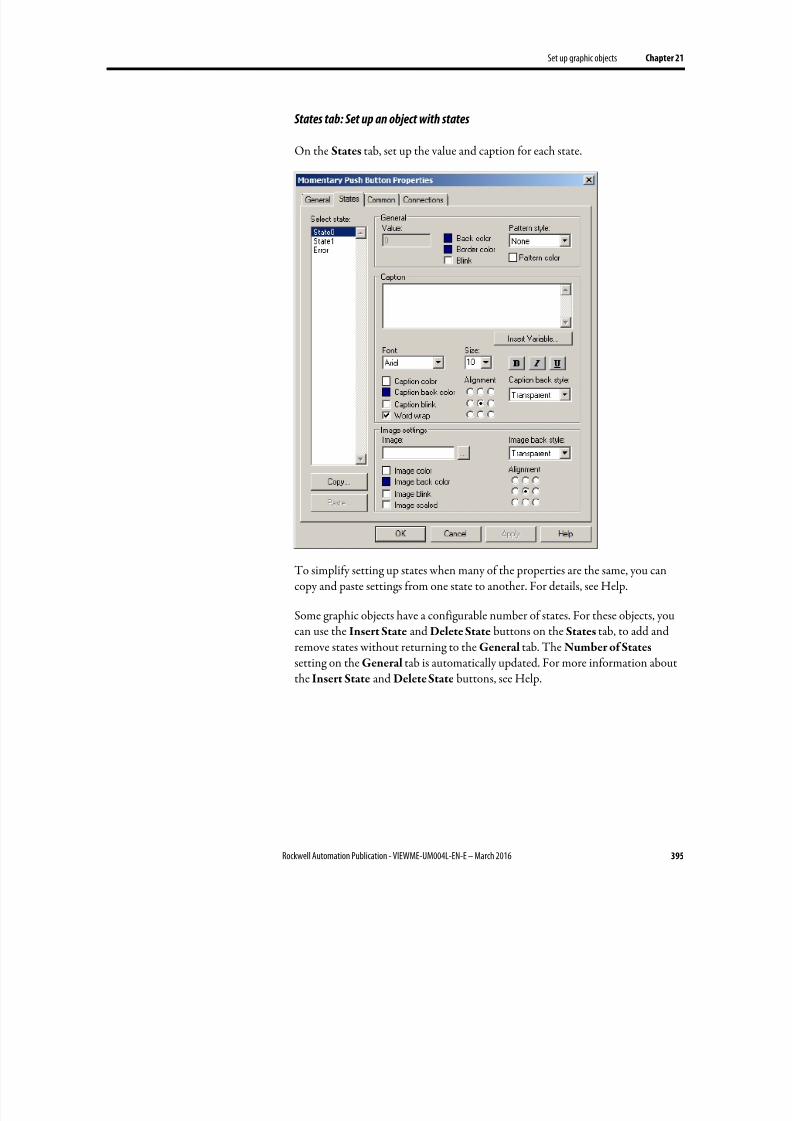
8/17/2019 FactoryTalk® View Machine Edition User's Guide
http://slidepdf.com/reader/full/factorytalk-view-machine-edition-users-guide 395/587
Set up graphic objects Chapter 21
Rockwell Automation Publication - VIEWME-UM004L-EN-E – March 2016 395
States tab: Set up an object with states
On the States tab, set up the value and caption for each state.
To simplify setting up states when many of the properties are the same, you cancopy and paste settings from one state to another. For details, see Help.
Some graphic objects have a configurable number of states. For these objects, youcan use the Insert State and Delete State buttons on the States tab, to add andremove states without returning to the General tab. The Number of States
setting on the General tab is automatically updated. For more information aboutthe Insert State and Delete State buttons, see Help.
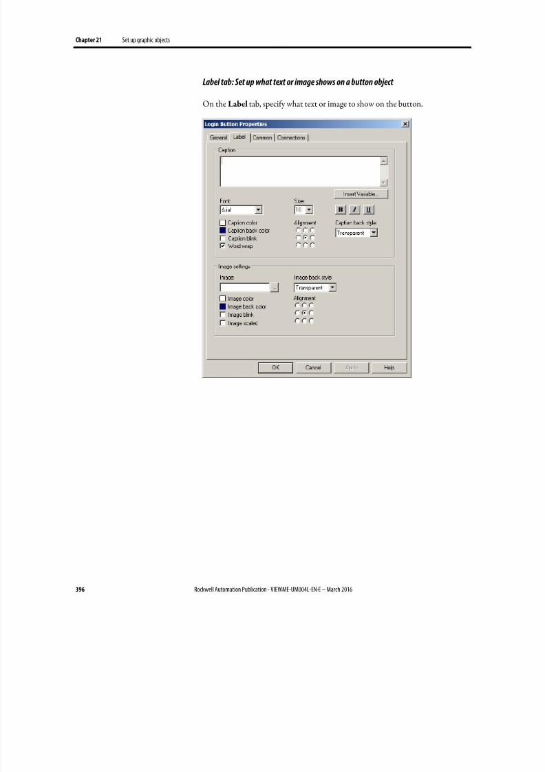
8/17/2019 FactoryTalk® View Machine Edition User's Guide
http://slidepdf.com/reader/full/factorytalk-view-machine-edition-users-guide 396/587
Chapter 21 Set up graphic objects
396 Rockwell Automation Publication - VIEWME-UM004L-EN-E – March 2016
Label tab: Set up what text or image shows on a button object
On the Label tab, specify what text or image to show on the button.
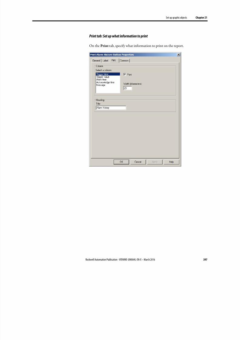
8/17/2019 FactoryTalk® View Machine Edition User's Guide
http://slidepdf.com/reader/full/factorytalk-view-machine-edition-users-guide 397/587
Set up graphic objects Chapter 21
Rockwell Automation Publication - VIEWME-UM004L-EN-E – March 2016 397
Print tab: Set up what information to print
On the Print tab, specify what information to print on the report.
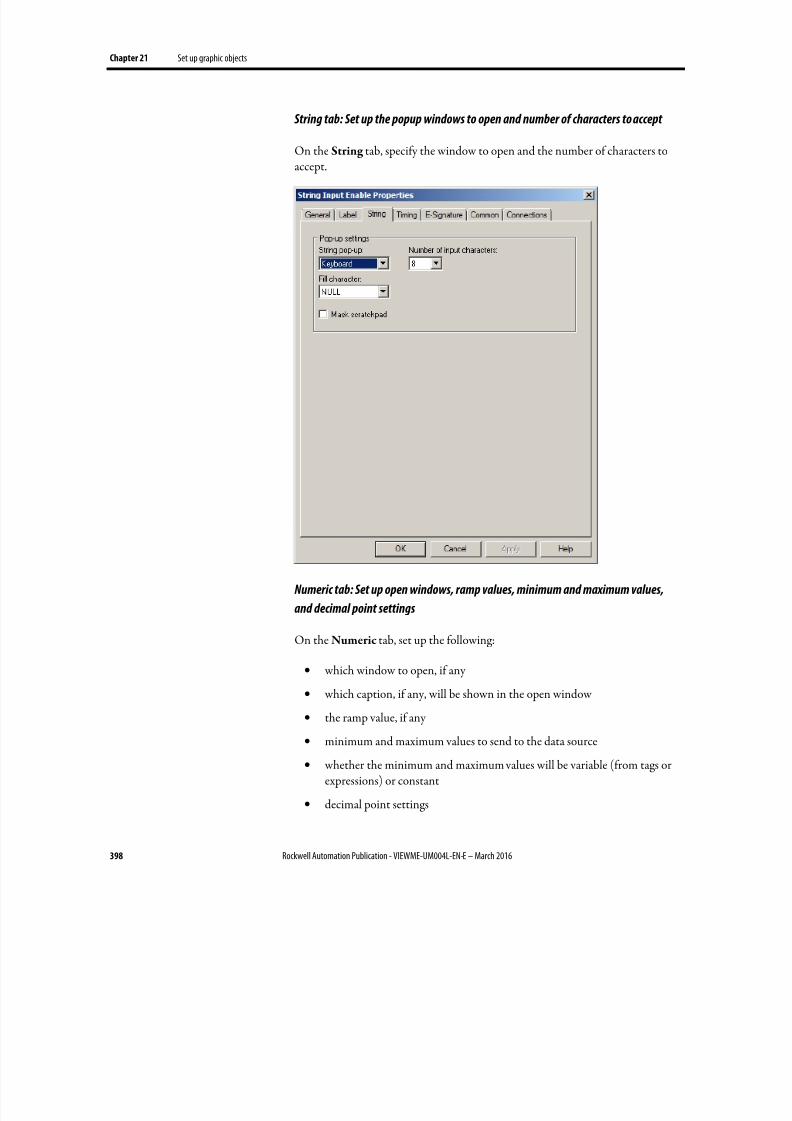
8/17/2019 FactoryTalk® View Machine Edition User's Guide
http://slidepdf.com/reader/full/factorytalk-view-machine-edition-users-guide 398/587
Chapter 21 Set up graphic objects
398 Rockwell Automation Publication - VIEWME-UM004L-EN-E – March 2016
String tab: Set up the popup windows to open and number of characters to accept
On the String tab, specify the window to open and the number of characters toaccept.
Numeric tab: Set up open windows, ramp values, minimum and maximum values,
and decimal point settings
On the Numeric tab, set up the following:
• which window to open, if any
•
which caption, if any, will be shown in the open window
• the ramp value, if any
• minimum and maximum values to send to the data source
• whether the minimum and maximum values will be variable (from tags orexpressions) or constant
• decimal point settings
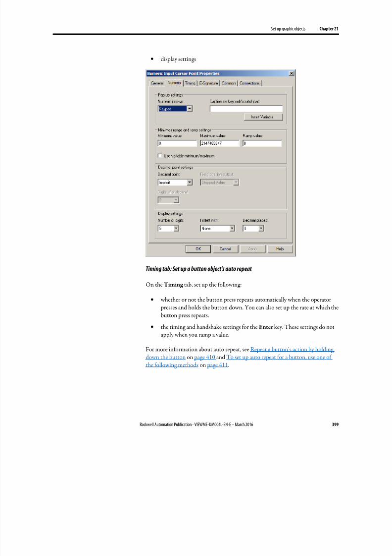
8/17/2019 FactoryTalk® View Machine Edition User's Guide
http://slidepdf.com/reader/full/factorytalk-view-machine-edition-users-guide 399/587
Set up graphic objects Chapter 21
Rockwell Automation Publication - VIEWME-UM004L-EN-E – March 2016 399
• display settings
Timing tab: Set up a button object's auto repeat
On the Timing tab, set up the following:
• whether or not the button press repeats automatically when the operator presses and holds the button down. You can also set up the rate at which thebutton press repeats.
• the timing and handshake settings for the Enter key. These settings do notapply when you ramp a value.
For more information about auto repeat, see Repeat a button’s action by holdingdown the button on page 410 and To set up auto repeat for a button, use one ofthe following methods on page 411.
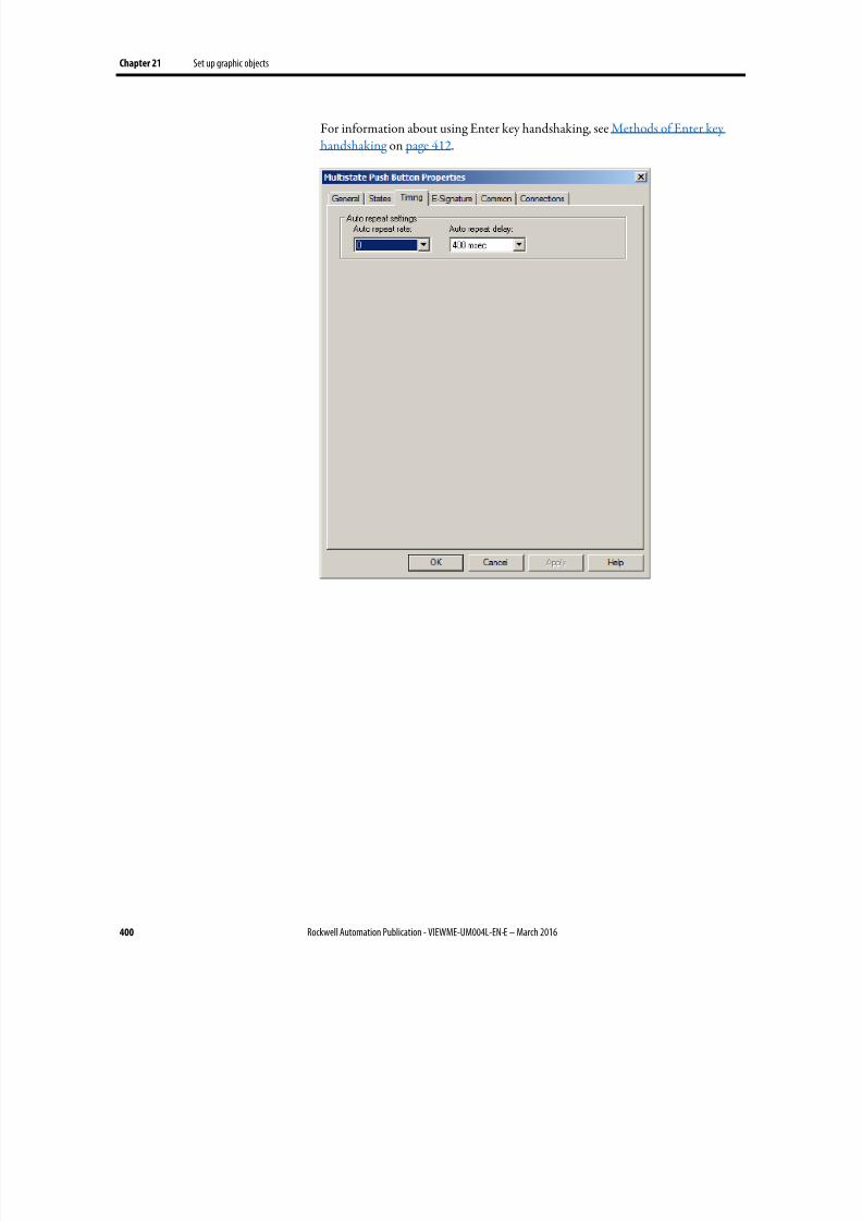
8/17/2019 FactoryTalk® View Machine Edition User's Guide
http://slidepdf.com/reader/full/factorytalk-view-machine-edition-users-guide 400/587
Chapter 21 Set up graphic objects
400 Rockwell Automation Publication - VIEWME-UM004L-EN-E – March 2016
For information about using Enter key handshaking, see Methods of Enter keyhandshaking on page 412.
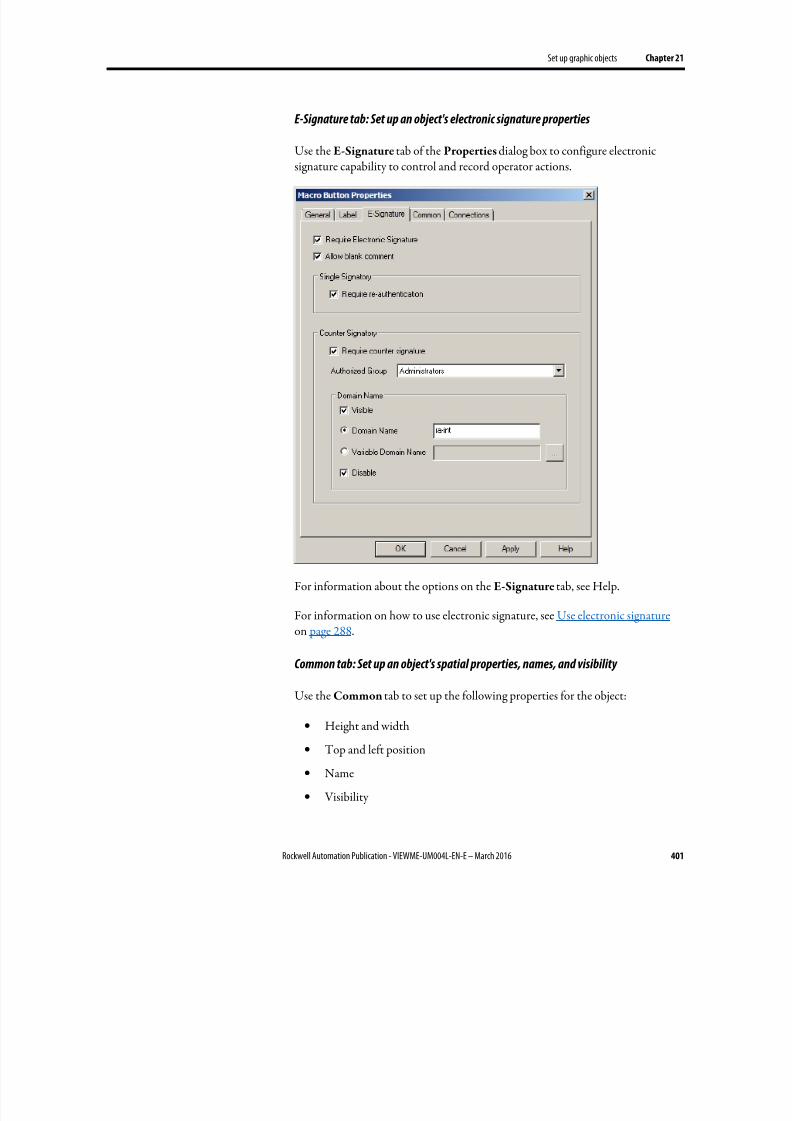
8/17/2019 FactoryTalk® View Machine Edition User's Guide
http://slidepdf.com/reader/full/factorytalk-view-machine-edition-users-guide 401/587
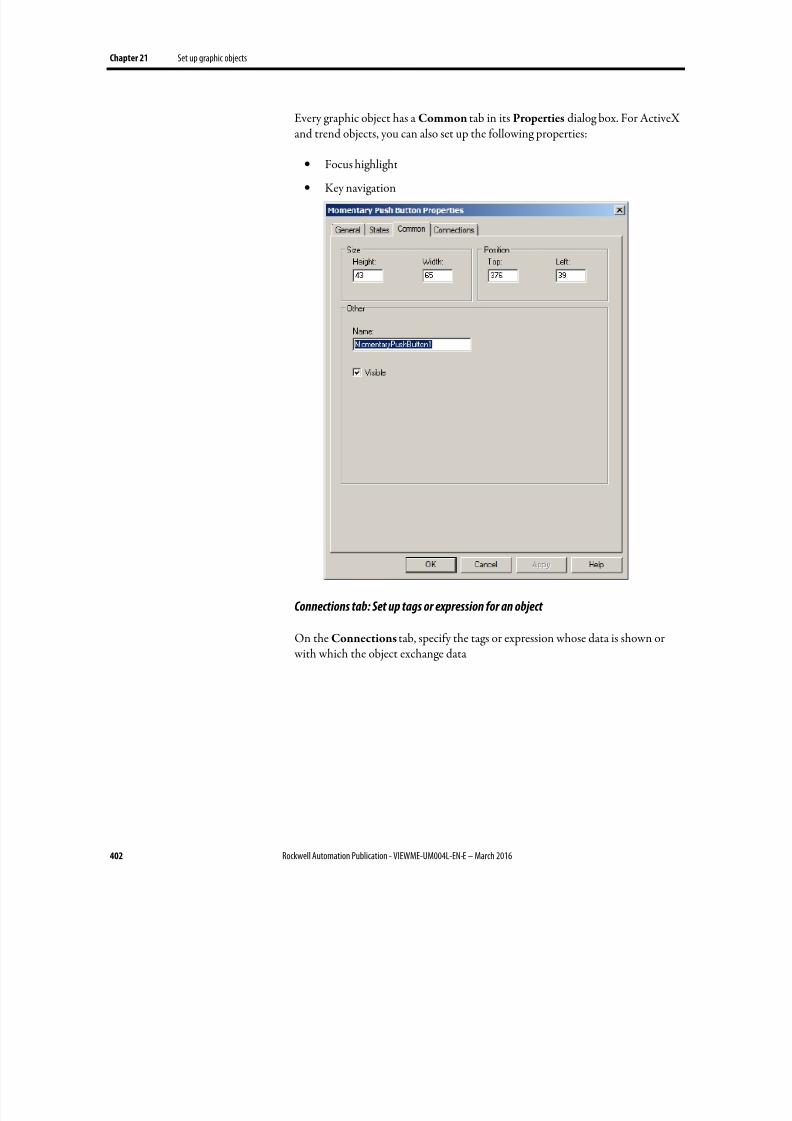
8/17/2019 FactoryTalk® View Machine Edition User's Guide
http://slidepdf.com/reader/full/factorytalk-view-machine-edition-users-guide 402/587
Chapter 21 Set up graphic objects
402 Rockwell Automation Publication - VIEWME-UM004L-EN-E – March 2016
Every graphic object has a Common tab in its Properties dialog box. For ActiveXand trend objects, you can also set up the following properties:
• Focus highlight
• Key navigation
Connections tab: Set up tags or expression for an object
On the Connections tab, specify the tags or expression whose data is shown or with which the object exchange data
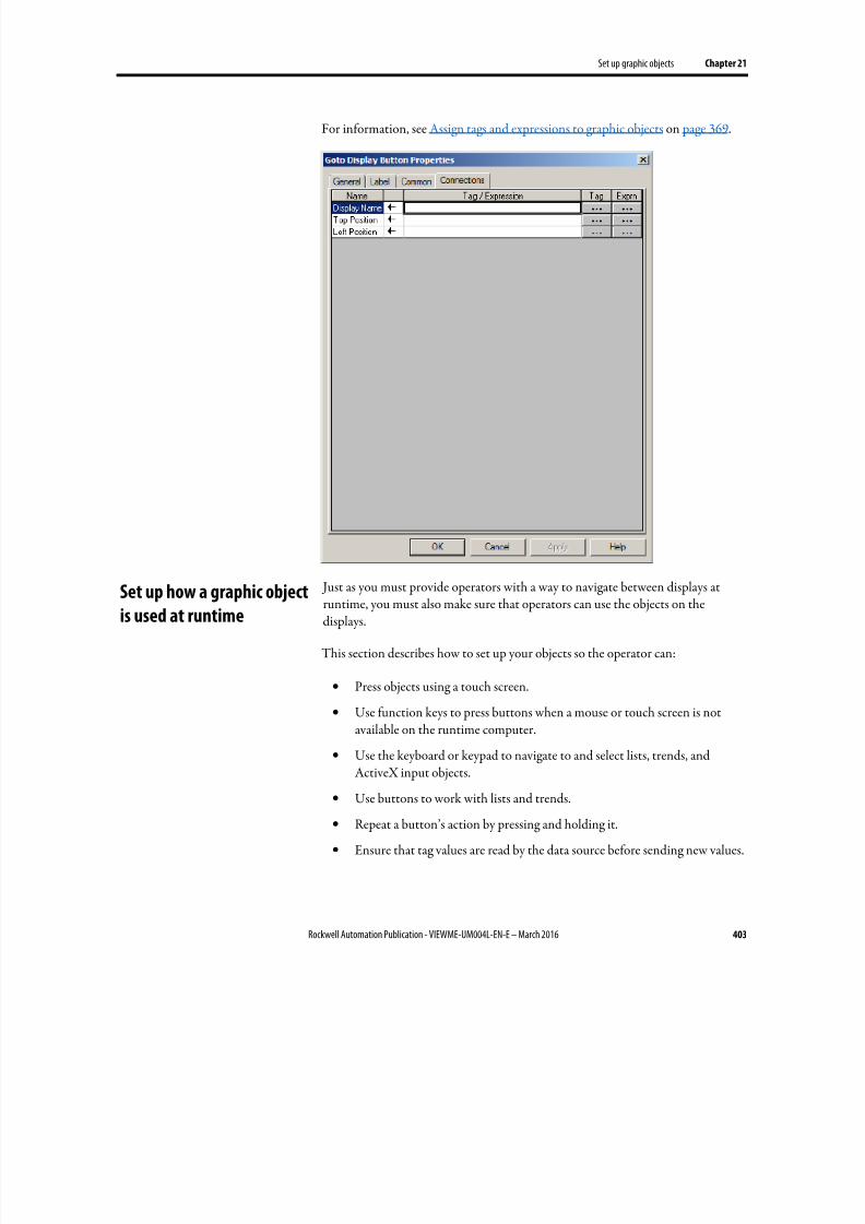
8/17/2019 FactoryTalk® View Machine Edition User's Guide
http://slidepdf.com/reader/full/factorytalk-view-machine-edition-users-guide 403/587
Set up graphic objects Chapter 21
Rockwell Automation Publication - VIEWME-UM004L-EN-E – March 2016 403
For information, see Assign tags and expressions to graphic objects on page 369.
Just as you must provide operators with a way to navigate between displays atruntime, you must also make sure that operators can use the objects on thedisplays.
This section describes how to set up your objects so the operator can:
• Press objects using a touch screen.
• Use function keys to press buttons when a mouse or touch screen is notavailable on the runtime computer.
•
Use the keyboard or keypad to navigate to and select lists, trends, andActiveX input objects.
• Use buttons to work with lists and trends.
• Repeat a button’s action by pressing and holding it.
• Ensure that tag values are read by the data source before sending new values.
Set up how a graphic object
is used at runtime
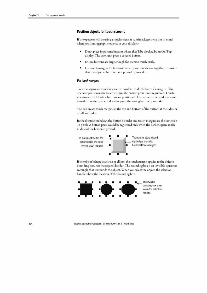
8/17/2019 FactoryTalk® View Machine Edition User's Guide
http://slidepdf.com/reader/full/factorytalk-view-machine-edition-users-guide 404/587
Chapter 21 Set up graphic objects
404 Rockwell Automation Publication - VIEWME-UM004L-EN-E – March 2016
Position objects for touch screens
If the operator will be using a touch screen at runtime, keep these tips in mind
when positioning graphic objects in your displays:
• Don’t place important buttons where they’ll be blocked by an On Topdisplay. The user can’t press a covered button.
• Ensure buttons are large enough for users to touch easily.
• Use touch margins for buttons that are positioned close together, to ensurethat the adjacent button is not pressed by mistake.
Use touch margins
Touch margins are touch-insensitive borders inside the button’s margin. If theoperator presses on the touch margin, the button press is not registered. Touchmargins are useful when buttons are positioned close to each other and you wantto make sure the operator does not press the wrong button by mistake.
You can create touch margins at the top and bottom of the button, at the sides, oron all four sides.
In the illustration below, the button’s border and touch margins are the same size,12 pixels. A button press would be registered only when the darker square in themiddle of the button is pressed.
If the object’s shape is a circle or ellipse, the touch margin applies to the object’sbounding box, not the object’s border. The bounding box is an invisible square orrectangle that surrounds the object. When you select the object, the selectionhandles show the location of the bounding box.
8/17/2019 FactoryTalk® View Machine Edition User's Guide
http://slidepdf.com/reader/full/factorytalk-view-machine-edition-users-guide 405/587
Set up graphic objects Chapter 21
Rockwell Automation Publication - VIEWME-UM004L-EN-E – March 2016 405
To create touch margins, use one of these methods
• On the General tab of the button’s Properties dialog box, type the numberof pixels for the touch margins in the Horizontal margin and Vertical
margin boxes.
• On the Properties tab of the Property Panel, type the number of pixels forthe HorizontalMargin and VerticalMargin properties.
Assign function keys to buttons
You can assign function keys to the buttons in your displays to allow the operatorto press the buttons using the function keys on the runtime terminal (or thefunction keys on a keyboard, if one is available). You can also assign a function key
to the numeric input cursor point.
You can assign up to 34 function keys to each graphic display.
Here are some tips for assigning function keys:
• Where possible, use the same function keys for the same operations in all your graphic displays. For example, if every display contains a Goto displaybutton that returns the operator to a graphic display called Main Menu,assign the same function key to this button in each display.
• Include the name of the function key assigned to a button in a caption on
the button.
For buttons with multiple states, include the function key name in the
caption for each state, or create a text object to use as a label for the button
(so that you don’t have to set up the caption for each state), and then group
the text and button together.
• If your application will run on a PanelView Plus 7, PanelView Plus 6,PanelView Plus, PanelView Plus Compact, or PanelView Plus CE terminal,assign keys that are supported by the runtime terminal. Different sizes ofterminals have different function keys.
Function key equivalents
If your application will run on a personal computer, the keyboard contains thefunction keys F1 to F12 only. The remaining function keys are associated withthese key combinations:
For this function key Use this key combination
F13 Left Shift+F1
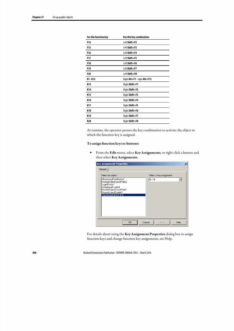
8/17/2019 FactoryTalk® View Machine Edition User's Guide
http://slidepdf.com/reader/full/factorytalk-view-machine-edition-users-guide 406/587
Chapter 21 Set up graphic objects
406 Rockwell Automation Publication - VIEWME-UM004L-EN-E – March 2016
For this function key Use this key combination
F14 Left Shift+F2
F15 Left Shift+F3
F16 Left Shift+F4
F17 Left Shift+F5
F18 Left Shift+F6
F19 Left Shift+F7
F20 Left Shift+F8
K1 - K12 Right Alt+F1 - right Alt+F12
K13 Right Shift+F1
K14 Right Shift+F2
K15 Right Shift+F3
K16 Right Shift+F4
K17 Right Shift+F5
K18 Right Shift+F6
K19 Right Shift+F7
K20 Right Shift+F8
At runtime, the operator presses the key combination to activate the object to which the function key is assigned.
To assign function keys to buttons:
•
From the Edit menu, select Key Assignments, or right-click a button andthen select Key Assignments.
For details about using the Key Assignment Properties dialog box to assignfunction keys and change function key assignments, see Help.

8/17/2019 FactoryTalk® View Machine Edition User's Guide
http://slidepdf.com/reader/full/factorytalk-view-machine-edition-users-guide 407/587
Set up graphic objects Chapter 21
Rockwell Automation Publication - VIEWME-UM004L-EN-E – March 2016 407
Use the keyboard to navigate to and select objects
If a mouse or touch screen is not available on the runtime computer, the operator
can use the keys on a keyboard or keypad to select (give focus to) these objects:
• Lists: control list selector, piloted control list selector, display list selector,diagnostics list, alarm list, and alarm status list
• Alarm banners
• Trends
• Numeric input enable buttons and String Input Enable buttons
• Numeric input cursor points
• RecipePlus table and selector
•
Third-party ActiveX input objects
What input focus looks like
The object with focus is surrounded by a highlight box, unless the DisableHighlight When Object has Focus box is selected (in the Display Settings dialogbox). You can specify the color of the highlight in this dialog box as well.
For ActiveX and trend objects, use the Common tab in the object’s Properties dialog box to specify whether or not to show a highlight box.
If the Disable Highlight When Object has Focus check box is selected in theDisplay Settings dialog box, that setting overrides the setting you specify on theCommon tab.
For more information about setting up options on the Common tab, see Help.
Use the keys on the keyboard or keypad
When a graphic display opens, the keyboard-navigable object that is closest to thetop left corner of the display is selected. The operator can use these keys to moveto and select a different object:
Use this key To do this
Tab Move from the upper left to the lower right.
8/17/2019 FactoryTalk® View Machine Edition User's Guide
http://slidepdf.com/reader/full/factorytalk-view-machine-edition-users-guide 408/587
Chapter 21 Set up graphic objects
408 Rockwell Automation Publication - VIEWME-UM004L-EN-E – March 2016
Use this key To do this
Shift+Tab Move from the lower right to the upper left.
Ctrl+arrow key Move left, right, up, or down.
Remove objects from and adding objects to the tab sequence
By default, you can use the keys to navigate to all lists, alarm banners, numericinput cursor points, trends, and ActiveX input objects in a display. However, youcan turn off key navigation for these objects if desired.
When an object’s key navigation is turned off, the operator can still select theobject using a mouse or touch screen, if available.
By default, key navigation is turned off for the Numeric Input Enable buttons andString Input Enable buttons. You can turn on keyboard navigation if you wantthe operator to use the keyboard to navigate to these objects.
To turn key navigation on or off, use one of these methods:
• On the Properties tab of the Property Panel, set the KeyNavigation
property to False for off, or True for on.
• For list objects, alarm banners, numeric input cursor points, Numeric
Input Enable buttons, and String Input Enable buttons, on the General
tab of the object’s Properties dialog box, clear the Key navigation box foroff, or select the box for on.
• For ActiveX and trend objects, on the Common tab of the object’sProperties dialog box, clear the Key navigation box for off, or select the boxfor on.
Link buttons to objects
Some FactoryTalk View buttons can be linked to specific trend, list, recipe, and
alarm banner objects, or you can set them up to work with whichever object hasfocus on the display.
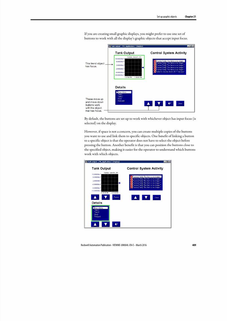
8/17/2019 FactoryTalk® View Machine Edition User's Guide
http://slidepdf.com/reader/full/factorytalk-view-machine-edition-users-guide 409/587
Set up graphic objects Chapter 21
Rockwell Automation Publication - VIEWME-UM004L-EN-E – March 2016 409
If you are creating small graphic displays, you might prefer to use one set ofbuttons to work with all the display’s graphic objects that accept input focus.
By default, the buttons are set up to work with whichever object has input focus (isselected) on the display.
However, if space is not a concern, you can create multiple copies of the buttons you want to use and link them to specific objects. One benefit of linking a buttonto a specific object is that the operator does not have to select the object before pressing the button. Another benefit is that you can position the buttons close to
the specified object, making it easier for the operator to understand which buttons work with which objects.
8/17/2019 FactoryTalk® View Machine Edition User's Guide
http://slidepdf.com/reader/full/factorytalk-view-machine-edition-users-guide 410/587
Chapter 21 Set up graphic objects
410 Rockwell Automation Publication - VIEWME-UM004L-EN-E – March 2016
To link a button to a specific object using the button’s Properties dialog box
1. Double-click the button to open its Properties dialog box.
2.
On the General tab, in the Send press to box, select Linked Object.
3. To select from a list of all the objects on the display that you can link thebutton to, click the Browse button next to the Linked object box.
4. Click the name of the object to link the button to, and then click OK .
5. Click OK to close the button’s Properties dialog box.
To link a button to a specific object using the Property Panel
•
On the Properties tab, specify the SendPressTo and LinkedObject properties.
Once you have linked buttons to an object, you might want to turn off the object’skey navigation, since this option is no longer needed. For details, see Removeobjects from and adding objects to the tab sequence on page 408.
Repeat a button’s action by holding down the button
To repeat a button’s action by pressing and holding it, set up auto repeat for the
button. If you set up auto repeat, when the operator presses and holds down thebutton, repeated button presses are registered until the operator releases thebutton.
A button press occurs when the operator clicks an object with the mouse, presses iton a touch screen, or presses the function key associated with the object. Autorepeat works with all these methods of pressing buttons.
You can use auto repeat with these buttons:
For this button Each button press does this
Multistate push Sends the value for the next state to the data source. External changes to the Valueconnection are not recognized when the button is in auto repeat mode.
Ramp Sends the new ramped value to the data source. External changes to the Value connectionare not recognized when the button is in auto repeat mode.
Move up Moves the highlight up an item in the list, recipe selector, or recipe table, scrolls up in thetrend, or ramps the numeric input cursor point or Numeric Input Enable button value.
Move down Moves the highlight down an item in the list, recipe selector, or recipe table, scrolls downin the trend, or ramps the numeric input cursor point or Numeric Input Enable buttonvalue.
8/17/2019 FactoryTalk® View Machine Edition User's Guide
http://slidepdf.com/reader/full/factorytalk-view-machine-edition-users-guide 411/587
Set up graphic objects Chapter 21
Rockwell Automation Publication - VIEWME-UM004L-EN-E – March 2016 411
For this button Each button press does this
Page up Moves the highlight up a page in the list, recipe selector, or recipe table.
Page down Moves the highlight down a page in the list, recipe selector, or recipe table.
Move left Scrolls the trend to the left.
Move right Scrolls the trend to the right.
For each button that uses auto repeat, you can specify these properties:
• Auto repeat rate — the number of times per second a button press isregistered when the button goes into auto repeat mode. The default rate is0, which means that auto repeat is turned off.
• Auto repeat delay — the length of time the button has to be pressed and
held down before auto repeat starts.
To set up auto repeat for a button, use one of the following methods
• On the Timing tab of the button’s Properties dialog box, specify the Auto
repeat rate and Auto repeat delay properties.
• On the Properties tab of the Property Panel, specify the AutoRepeatRate
and AutoRepeatDelay properties.
Ensure values are read by the data source before sending new values
To ensure a value is read by the data source before the operator sends a new value,use Enter key handshaking . While Enter key handshaking is in effect for anobject, the operator cannot send a new value to the object’s Value connection.
You can use Enter key handshaking with these graphic objects:
• Control list selector
• Piloted control list selector
• Numeric input enable button
• String Input Enable button
• Numeric input cursor point
If Enter key handshaking is in effect for one of these objects, the operator can still provide input to other objects in the graphic display.
If the graphic display is closed while Enter key handshaking is in effect, thehandshaking is canceled.
8/17/2019 FactoryTalk® View Machine Edition User's Guide
http://slidepdf.com/reader/full/factorytalk-view-machine-edition-users-guide 412/587
Chapter 21 Set up graphic objects
412 Rockwell Automation Publication - VIEWME-UM004L-EN-E – March 2016
Methods of Enter key handshaking
Enter key handshaking works by setting the object’s Enter connection to 1. As
long as theEnter
connection is set to 1, new values cannot be sent to the Value
connection. How the Enter connection is reset to 0 depends on how you set upEnter key handshaking .
There are two ways you can use Enter key handshaking :
• To hold the value at the data source for a specific period of time.
• To hold the value at the data source until the data source notifiesFactoryTalk View that the value has been read.
Choose the method that best suits your application needs and communication
system.
Hold the value for a specific period of time
To set up an object’s Enter key handshaking so that the value at the Value
connection is held for a specific period of time, assign a tag to the Enter connection and specify the Enter key hold time. You can also specify an Enter keycontrol delay, if desired.
This method of Enter key handshaking works as follows:
1.
When the operator presses the Enter button, the value is sent to the Valueconnection and the Enter key control delay timer begins timing. (The useof a delay is optional.)
2. If you specify an Enter key control delay, when the time is up, the Enter
connection is set to 1. If you don’t use the delay, the Enter connection is setto 1 as soon as the operator presses Enter .
As long as the Enter connection is set to 1, the operator cannot send new
values to the data source.
3. When the Enter connection is set to 1, the Enter key hold time timer
begins timing.
4. When the Enter key hold time has expired, the Enter connection is reset to0 and the operator can send a new value to the Value connection.
To set up Enter key handshaking to hold the value for a specific period of time
1. On Timing tab of the object’s Properties dialog box, specify the Enter keycontrol dela y (optional) and Enter key hold time properties.
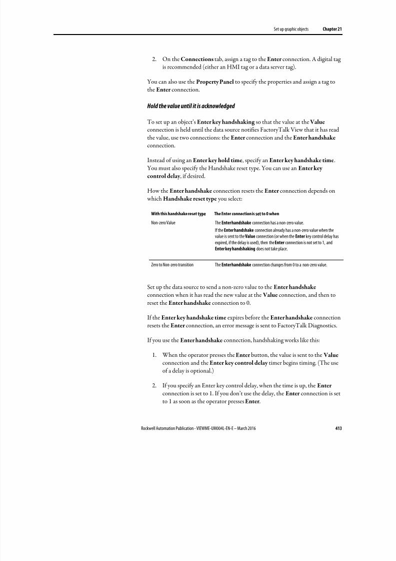
8/17/2019 FactoryTalk® View Machine Edition User's Guide
http://slidepdf.com/reader/full/factorytalk-view-machine-edition-users-guide 413/587
Set up graphic objects Chapter 21
Rockwell Automation Publication - VIEWME-UM004L-EN-E – March 2016 413
2. On the Connections tab, assign a tag to the Enter connection. A digital tagis recommended (either an HMI tag or a data server tag).
You can also use the Property Panel to specify the properties and assign a tag to
the Enter connection.
Hold the value until it is acknowledged
To set up an object’s Enter key handshaking so that the value at the Valueconnection is held until the data source notifies FactoryTalk View that it has readthe value, use two connections: the Enter connection and the Enter handshakeconnection.
Instead of using an Enter key hold time, specify an Enter key handshake time.You must also specify the Handshake reset type. You can use an Enter key
control delay , if desired.
How the Enter handshake connection resets the Enter connection depends on which Handshake reset type you select:
With this handshake reset type The Enter connection is set to 0 when
Non-zero Value The Enter handshake connection has a non-zero value.
If the Enter handshake connection already has a non-zero value when thevalue is sent to the Value connection (or when the Enter key control delay hasexpired, if the delay is used), then the Enter connection is not set to 1, andEnter key handshaking does not take place.
Zero to Non-zero transition The Enter handshake connection changes from 0 to a non-zero value.
Set up the data source to send a non-zero value to the Enter handshake
connection when it has read the new value at the Value connection, and then toreset the Enter handshake connection to 0.
If the Enter key handshake time expires before the Enter handshake connectionresets the Enter connection, an error message is sent to FactoryTalk Diagnostics.
If you use the Enter handshake connection, handshaking works like this:
1. When the operator presses the Enter button, the value is sent to the Valueconnection and the Enter key control delay timer begins timing. (The useof a delay is optional.)
2. If you specify an Enter key control delay, when the time is up, the Enter
connection is set to 1. If you don’t use the delay, the Enter connection is setto 1 as soon as the operator presses Enter .
8/17/2019 FactoryTalk® View Machine Edition User's Guide
http://slidepdf.com/reader/full/factorytalk-view-machine-edition-users-guide 414/587
Chapter 21 Set up graphic objects
414 Rockwell Automation Publication - VIEWME-UM004L-EN-E – March 2016
As long as the Enter connection is set to 1, the operator cannot send new
values to the data source.
If the Handshake reset type is Non-zero Value, the Enter handshake
connection must be 0 when the delay expires in order to set the Enter
connection to 1.
3. When the Enter connection is set to 1, the Enter key handshake time timer begins timing.
4. The Enter connection remains set until the Enter key handshake time expires or until reset by the Enter handshake connection, whicheverhappens first.
5. The Enter connection is reset to 0 and the operator can send a new value to
the Value connection.
To set up Enter key handshaking to hold the value until the data source has
read it
1. In the Timing tab of the object’s Properties dialog box, specify these properties:
• Enter key control delay (optional)
• Enter key handshake time
•
Handshake reset type
2. In the Connections tab, assign these connections:
• Enter — assign a tag. A digital tag is recommended (either an HMI tagor a data server tag).
• Enter handshake — assign a tag or expression.
3. Set up the data source to send a non-zero value to the Enter handshake
connection when it has read the new value at the Value connection, andthen to reset the Enter handshake connection to 0.
You can also use the Property Panel to specify the properties and assign tags tothe connections.

8/17/2019 FactoryTalk® View Machine Edition User's Guide
http://slidepdf.com/reader/full/factorytalk-view-machine-edition-users-guide 415/587
Set up graphic objects Chapter 21
Rockwell Automation Publication - VIEWME-UM004L-EN-E – March 2016 415
Graphic objects use the time, date, and number format of the current applicationlanguage. For example, if the application language uses a comma for the decimalsymbol, floating-point values shown in graphic objects uses a comma for thedecimal symbol.
For information about using multiple languages, see Set up language switching on page 199.
Time, date, and number
formats for graphic objects

8/17/2019 FactoryTalk® View Machine Edition User's Guide
http://slidepdf.com/reader/full/factorytalk-view-machine-edition-users-guide 416/587
Chapter 21 Set up graphic objects
416 Rockwell Automation Publication - VIEWME-UM004L-EN-E – March 2016
8/17/2019 FactoryTalk® View Machine Edition User's Guide
http://slidepdf.com/reader/full/factorytalk-view-machine-edition-users-guide 417/587
Rockwell Automation Publication - VIEWME-UM004L-EN-E – March 2016 417
Chapter 22
Animate graphic objects
This chapter describes:
• The types of animation and which objects support which types ofanimation
• Use the Animation dialog box
• Test animation
• Use tag names, tag placeholders, and expressions when attaching animation
• Set the minimum and maximum values for animation that uses a range ofmotion
• Use Object Smart Path to define an object’s range of motion
• Set up each type of animation
• Apply animation to groups
• Check what kind of animation is attached to an object
•
Copy and paste animation• Set up animation for global objects
Animation associates graphic objects with tags so the appearance or position of anobject changes to reflect changes to the tag’s value. For example, an object’s colorcould change from yellow to orange to red as the tag’s value increases. Or a slidercould move from left to right as a tag’s value increases.
You can use these types of animation:
• Color
•
Fill
• Height
• Horizontal position
• Horizontal slider
• Rotation
• Vertical position
Types of animation
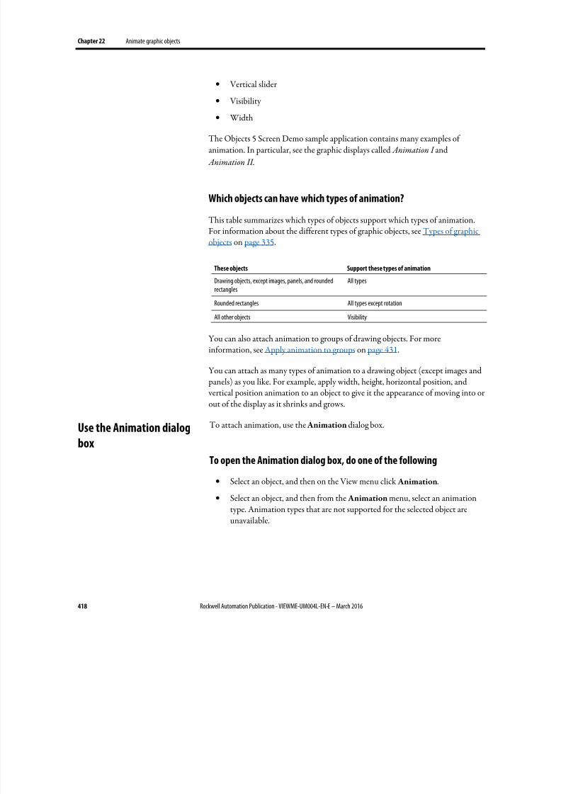
8/17/2019 FactoryTalk® View Machine Edition User's Guide
http://slidepdf.com/reader/full/factorytalk-view-machine-edition-users-guide 418/587
Chapter 22 Animate graphic objects
418 Rockwell Automation Publication - VIEWME-UM004L-EN-E – March 2016
• Vertical slider
• Visibility
• Width
The Objects 5 Screen Demo sample application contains many examples ofanimation. In particular, see the graphic displays called Animation I and
Animation II .
Which objects can have which types of animation?
This table summarizes which types of objects support which types of animation.For information about the different types of graphic objects, see Types of graphic
objects on page 335.
These objects Support these types of animation
Drawing objects, except images, panels, and roundedrectangles
All types
Rounded rectangles All types except rotation
All other objects Visibility
You can also attach animation to groups of drawing objects. For moreinformation, see Apply animation to groups on page 431.
You can attach as many types of animation to a drawing object (except images and panels) as you like. For example, apply width, height, horizontal position, and vertical position animation to an object to give it the appearance of moving into orout of the display as it shrinks and grows.
To attach animation, use the Animation dialog box.
To open the Animation dialog box, do one of the following
• Select an object, and then on the View menu click Animation.
•
Select an object, and then from the Animation menu, select an animationtype. Animation types that are not supported for the selected object areunavailable.
Use the Animation dialog
box
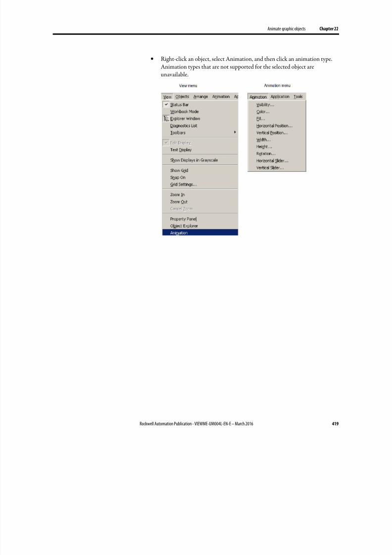
8/17/2019 FactoryTalk® View Machine Edition User's Guide
http://slidepdf.com/reader/full/factorytalk-view-machine-edition-users-guide 419/587
Animate graphic objects Chapter 22
Rockwell Automation Publication - VIEWME-UM004L-EN-E – March 2016 419
• Right-click an object, select Animation, and then click an animation type.Animation types that are not supported for the selected object areunavailable.
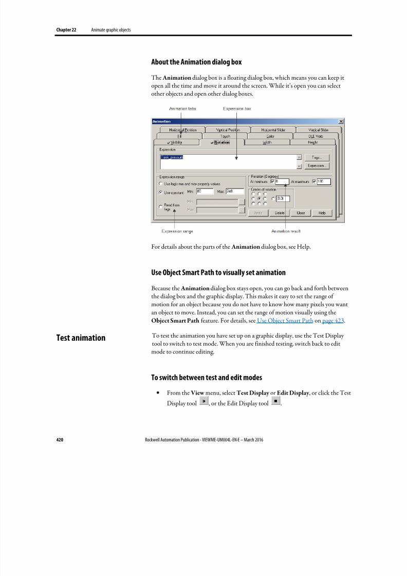
8/17/2019 FactoryTalk® View Machine Edition User's Guide
http://slidepdf.com/reader/full/factorytalk-view-machine-edition-users-guide 420/587
Chapter 22 Animate graphic objects
420 Rockwell Automation Publication - VIEWME-UM004L-EN-E – March 2016
About the Animation dialog box
The Animation dialog box is a floating dialog box, which means you can keep it
open all the time and move it around the screen. While it’s open you can selectother objects and open other dialog boxes.
For details about the parts of the Animation dialog box, see Help.
Use Object Smart Path to visually set animation
Because the Animation dialog box stays open, you can go back and forth betweenthe dialog box and the graphic display. This makes it easy to set the range ofmotion for an object because you do not have to know how many pixels you wantan object to move. Instead, you can set the range of motion visually using theObject Smart Path feature. For details, see Use Object Smart Path on page 423.
To test the animation you have set up on a graphic display, use the Test Displaytool to switch to test mode. When you are finished testing, switch back to editmode to continue editing.
To switch between test and edit modes
• From the View menu, select Test Display or Edit Display , or click the Test
Display tool , or the Edit Display tool .
Test animation
8/17/2019 FactoryTalk® View Machine Edition User's Guide
http://slidepdf.com/reader/full/factorytalk-view-machine-edition-users-guide 421/587
Animate graphic objects Chapter 22
Rockwell Automation Publication - VIEWME-UM004L-EN-E – March 2016 421
Tip: Test mode is not the same as running the display. Test mode does not change theappearance or position of the display as s et up in the Display Settings dialog box. Also,data logging is not turned on in test mode.
When setting up animation for objects, you are linking objects to tags. You canspecify a tag name or use tag placeholder.
You can use HMI tags or data server tags that already exist, or you can use a newtag name.
Tag placeholders allow you to create displays that can be used with different tags.
You can use tag placeholders in:
•
The graphic display that opens when the application is first run.
• Graphic displays that are opened using a Goto display button.
• Graphic displays that are opened using a display list selector.
• The graphic display that opens when the logout button is pressed.
• The graphic display that opens when auto logout is used.
• Graphic displays that are opened using the Remote Display Number globalconnection.
Use parameter files or parameter lists to specify which tags or folders to substitutefor which placeholders. For global objects, you can specify the tags or folders oftags using global object parameters. For more information about using parameterfiles, parameter lists, and global object parameters, see Use parameters and globalobjects on page 461.
The tag placeholder can replace any part of a tag name, including folder names.For example, you could create a parameter file specifying that the tag placeholder#1=Folder1. You could assign the folder and a tag name to a graphic object’sconnection: #1\Tag1.
To create a tag placeholder
• In the Expression box, type the cross-hatch character followed by a number(no space in between). For example, #1.
Many types of animation can be achieved using expressions. You can useexpressions containing tag values, constants, mathematical equations, securityfunctions, and if-then-else logic. A tag name or tag placeholder can be included as part of an expression, or it can stand alone as the entire expression.
Use tag names and tag
placeholders
Use expressions
8/17/2019 FactoryTalk® View Machine Edition User's Guide
http://slidepdf.com/reader/full/factorytalk-view-machine-edition-users-guide 422/587
Chapter 22 Animate graphic objects
422 Rockwell Automation Publication - VIEWME-UM004L-EN-E – March 2016
For more information about expressions, see Use expressions on page 435.
Many types of animation require a minimum and maximum range for the tag orexpression. These values determine the start and end points for a range of motion.
For example, if you specify a minimum of 0 and a maximum of 100, the object willnot react to values outside of this range. So, even if the expression has a value of200, the object does not change from its At maximum position.
When setting up animation, select one of these methods for calculating theminimum and maximum values:
• Use tag’s min and max property values — select this method to use theminimum and maximum values of the first HMI tag in the expression. Ifmore than one HMI tag is used in the expression, the first HMI tag’s
minimum and maximum values are used.For analog HMI tags, the values are taken from the Minimum and
Maximum boxes in the Tags editor. For digital tags, the minimum is 0 and
the maximum is 1.
• Use constant — select this method to use numeric constants. Type theminimum and maximum values in the boxes.
• Read from tags — select this method to read two tags’ values to determinethe minimum and maximum values. Type the tag names in the boxes, or
click the Browse buttons to open the Tag Browser and select the tags.
If you use this method, the tags are read when the graphic display opens.
Their values at that time are used for the minimum and maximum values.
The tags are not read again after this.
To define a range of motion for an object, do one of the following:
• Use the mouse to move the object on the display. This uses the Object
Smart Path feature to visually define the range of motion.
• Type values in the At minimum and At maximum boxes.
Motion can be defined in pixels, percentages, or degrees.
Animation that does not use a range of motion
Visibility and color animation do not use a range of motion, because these types ofanimation represent a change of state, not a range of values.
Set minimum and
maximum values
Define a range of motion
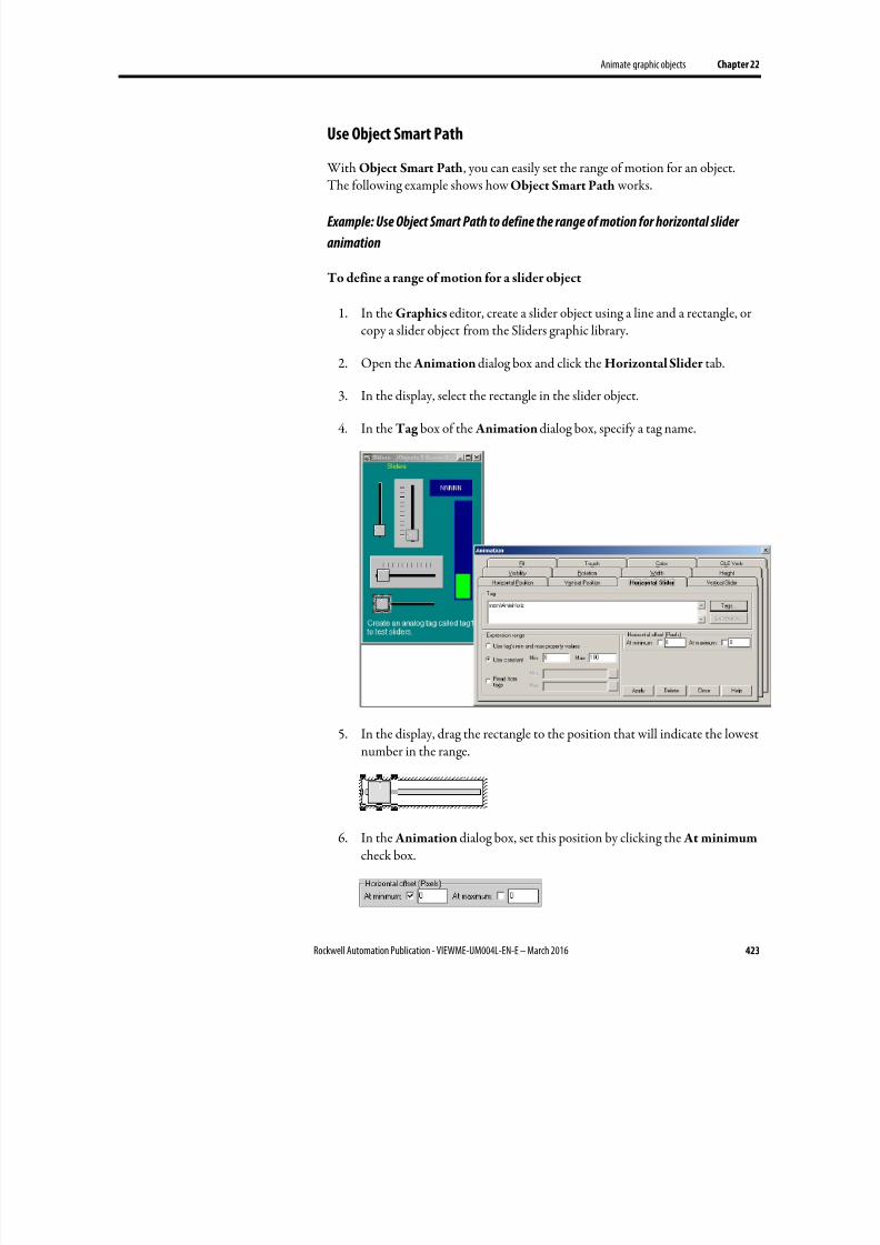
8/17/2019 FactoryTalk® View Machine Edition User's Guide
http://slidepdf.com/reader/full/factorytalk-view-machine-edition-users-guide 423/587
Animate graphic objects Chapter 22
Rockwell Automation Publication - VIEWME-UM004L-EN-E – March 2016 423
Use Object Smart Path
With Object Smart Path, you can easily set the range of motion for an object.
The following example shows how Object Smart Path works.
Example: Use Object Smart Path to define the range of motion for horizontal slider
animation
To define a range of motion for a slider object
1. In the Graphics editor, create a slider object using a line and a rectangle, orcopy a slider object from the Sliders graphic library.
2. Open the Animation dialog box and click the Horizontal Slider tab.
3.
In the display, select the rectangle in the slider object.
4. In the Tag box of the Animation dialog box, specify a tag name.
5. In the display, drag the rectangle to the position that will indicate the lowestnumber in the range.
6. In the Animation dialog box, set this position by clicking the At minimum check box.
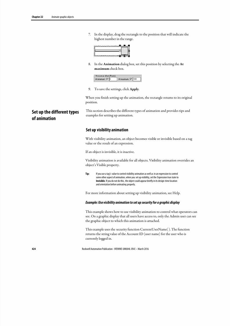
8/17/2019 FactoryTalk® View Machine Edition User's Guide
http://slidepdf.com/reader/full/factorytalk-view-machine-edition-users-guide 424/587
Chapter 22 Animate graphic objects
424 Rockwell Automation Publication - VIEWME-UM004L-EN-E – March 2016
7. In the display, drag the rectangle to the position that will indicate thehighest number in the range.
8. In the Animation dialog box, set this position by selecting the At
maximum check box.
9.
To save the settings, click Apply .
When you finish setting up the animation, the rectangle returns to its original
position.
This section describes the different types of animation and provides tips andexamples for setting up animation.
Set up visibility animation
With visibility animation, an object becomes visible or invisible based on a tag value or the result of an expression.
If an object is invisible, it is inactive.
Visibility animation is available for all objects. Visibility animation overrides anobject’s Visible property.
Tip: If you use a tag’s value to control visibility animation as well as in an expression to controlsome other aspect of animation, when you set up visibility, set the Expression true state toInvisible. If you do not do this, the object could appear briefly in its design-time locationand orientation before animating properly.
For more information about setting up visibility animation, see Help.
Example: Use visibility animation to set up security for a graphic display
This example shows how to use visibility animation to control what operators cansee. On a graphic display that all users have access to, only the Admin user can seethe graphic object to which this animation is attached.
This example uses the security function CurrentUserName( ). The functionreturns the string value of the Account ID (user name) for the user who iscurrently logged in.
Set up the different types
of animation
8/17/2019 FactoryTalk® View Machine Edition User's Guide
http://slidepdf.com/reader/full/factorytalk-view-machine-edition-users-guide 425/587
Animate graphic objects Chapter 22
Rockwell Automation Publication - VIEWME-UM004L-EN-E – March 2016 425
The CurrentUserName( ) function is case sensitive. All user names use uppercaseletters, so make sure that you use uppercase letters in your expression.
To specify which user can view an object in a display
1. Select the object to limit visibility to.
2. Open the Animation dialog box and click the Visibility tab.
3. In the Expression box, type this:
CurrentUserName( ) == "ADMIN"
4. For the Expression true state, select Visible.
5.
Click Apply , and then click Close.
At runtime, the object is visible only if the Admin user is logged in.
Set up color animation
With color animation, an object changes color based on a tag value or the result ofan expression. You can specify up to 16 color changes (A to P) for any object.Colors can be solid or blinking. For each color change, specify the value orthreshold at which the color is to change and specify the colors to change to. Atruntime, when the value reaches or crosses the threshold, the color changes.
Choosing between Solid, Gradient, Original, and Shaded fill styles allows formore animation options for the blinking object.
• Solid - Allows you to change the colors, and they will have a solid look tothem.
• Gradient - Allows you to change the colors, and they will have a gradientlook to them. If you select Gradient as the Fill Style, the Fill color boxchanges to gradient. Click it to bring up the gradient fill dialog box toconfigure the gradient fill.
•
Original - Retains the colors and the shading of the object as it wasimported. Both the line and fill color can be altered from the original usingBlink.
• Shaded - Uses a tight dot pattern to soften or give a shaded appearance.This fill style takes effect only on the group object that is composed ofindividual objects with dark to light colors, such as the Symbol Factoryobjects.
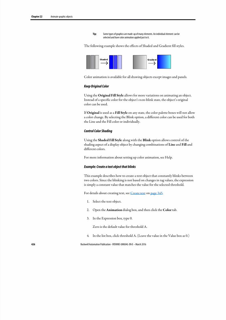
8/17/2019 FactoryTalk® View Machine Edition User's Guide
http://slidepdf.com/reader/full/factorytalk-view-machine-edition-users-guide 426/587
Chapter 22 Animate graphic objects
426 Rockwell Automation Publication - VIEWME-UM004L-EN-E – March 2016
Tip: Some types of graphics are made up of many elements. An individual element can beselected and have color animation applied just to it.
The following example shows the effects of Shaded and Gradient fill styles.
Color animation is available for all drawing objects except images and panels.
Keep Original Color
Using the Original Fill Style allows for more variations on animating an object.
Instead of a specific color for the object’s non-blink state, the object’s originalcolor can be used.
If Original is used as a Fill Style on any state, the color palette boxes will not allowa color change. By selecting the Blink option, a different color can be used for boththe Line and the Fill color or individually.
Control Color Shading
Using the Shaded Fill Style along with the Blink option allows control of theshading aspect of a display object by changing combinations of Line and Fill and
different colors.
For more information about setting up color animation, see Help.
Example: Create a text object that blinks
This example describes how to create a text object that constantly blinks betweentwo colors. Since the blinking is not based on changes in tag values, the expressionis simply a constant value that matches the value for the selected threshold.
For details about creating text, see Create text on page 345.
1.
Select the text object.
2.
Open the Animation dialog box, and then click the Color tab.
3. In the Expression box, type 0.
Zero is the default value for threshold A.
4. In the list box, click threshold A. (Leave the value in the Value box as 0.)
8/17/2019 FactoryTalk® View Machine Edition User's Guide
http://slidepdf.com/reader/full/factorytalk-view-machine-edition-users-guide 427/587
Animate graphic objects Chapter 22
Rockwell Automation Publication - VIEWME-UM004L-EN-E – March 2016 427
5. For the line color, click Blink . (If desired, click Blink for the fill color too.)
6. For each color, click the color box, and then click the color to use.
7.
Click Apply .
Example: Create an object that changes color as the fill level changes
This example describes how to create a rectangle object that changes color as theobject’s fill level increases. This example uses a tag called Hopper1\FlourLevel.The tag has a range of 1 to 100. When the flour level reaches 80, the rectangleblinks between gray and yellow to warn the operator that the hopper is nearly full. When the flour level reaches 95, the rectangle blinks between gray and red.
You could use a bar graph object (without animation) to achieve a similar result.
1. Double-click the rectangle to open the Polygon Properties dialog box.Assign these properties to the rectangle:
• In the Back style box, select Solid.
• For the Fore color and Back color , select gray .
2.
Click OK to close the Polygon Properties dialog box.
3. With the rectangle selected, open the Animation dialog box, and then clickthe Fill tab.
4. Attach fill animation as follows:
• In the Expression box, type Hopper1\FlourLevel (this is the tag that
monitors the fill level).
• For Fill Direction, click Up.
5. Click the Color tab, and then attach color animation as follows:
• In the Expression box, type Hopper1\FlourLevel (the same tag that was
used in the Fill tab).
6.
Set up the color for the normal state
• In the List box, select A. (In the Value box, leave the value as 0.)
• For Fill Style, select Solid.
• For Line and Fill, select the color box, and then select gray (the samegray used for the rectangle).
7.
Set up the color for the first warning
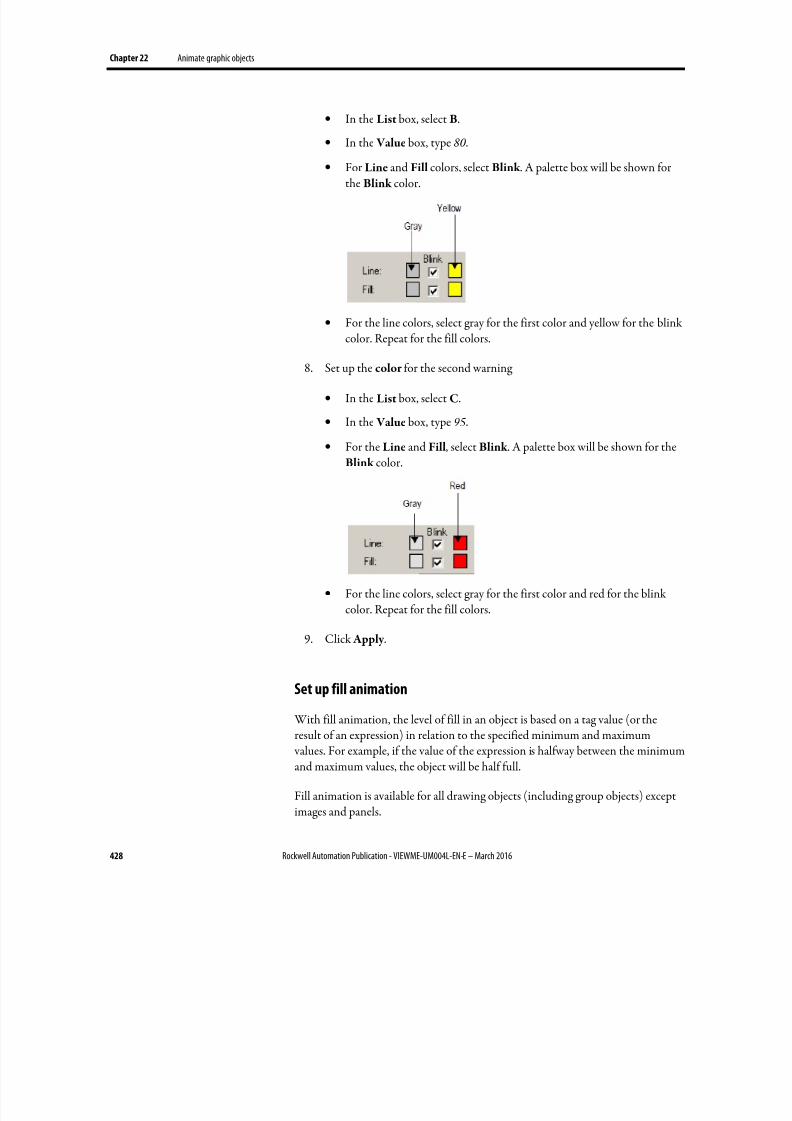
8/17/2019 FactoryTalk® View Machine Edition User's Guide
http://slidepdf.com/reader/full/factorytalk-view-machine-edition-users-guide 428/587
Chapter 22 Animate graphic objects
428 Rockwell Automation Publication - VIEWME-UM004L-EN-E – March 2016
• In the List box, select B.
• In the Value box, type 80 .
•
For Line and Fill colors, select Blink . A palette box will be shown forthe Blink color.
• For the line colors, select gray for the first color and yellow for the blinkcolor. Repeat for the fill colors.
8. Set up the color for the second warning
• In the List box, select C.
• In the Value box, type 95.
• For the Line and Fill, select Blink . A palette box will be shown for theBlink color.
• For the line colors, select gray for the first color and red for the blinkcolor. Repeat for the fill colors.
9. Click Apply .
Set up fill animation With fill animation, the level of fill in an object is based on a tag value (or theresult of an expression) in relation to the specified minimum and maximum values. For example, if the value of the expression is halfway between the minimumand maximum values, the object will be half full.
Fill animation is available for all drawing objects (including group objects) exceptimages and panels.
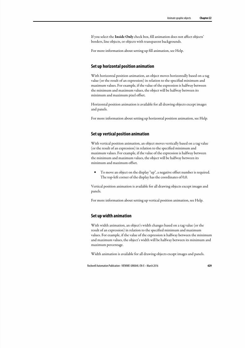
8/17/2019 FactoryTalk® View Machine Edition User's Guide
http://slidepdf.com/reader/full/factorytalk-view-machine-edition-users-guide 429/587
Animate graphic objects Chapter 22
Rockwell Automation Publication - VIEWME-UM004L-EN-E – March 2016 429
If you select the Inside Only check box, fill animation does not affect objects’borders, line objects, or objects with transparent backgrounds.
For more information about setting up fill animation, see Help.
Set up horizontal position animation
With horizontal position animation, an object moves horizontally based on a tag value (or the result of an expression) in relation to the specified minimum andmaximum values. For example, if the value of the expression is halfway betweenthe minimum and maximum values, the object will be halfway between itsminimum and maximum pixel offset.
Horizontal position animation is available for all drawing objects except images
and panels.
For more information about setting up horizontal position animation, see Help.
Set up vertical position animation
With vertical position animation, an object moves vertically based on a tag value(or the result of an expression) in relation to the specified minimum andmaximum values. For example, if the value of the expression is halfway betweenthe minimum and maximum values, the object will be halfway between its
minimum and maximum offset.
• To move an object on the display "up", a negative offset number is required.The top-left corner of the display has the coordinates of 0,0.
Vertical position animation is available for all drawing objects except images and panels.
For more information about setting up vertical position animation, see Help.
Set up width animation
With width animation, an object’s width changes based on a tag value (or theresult of an expression) in relation to the specified minimum and maximum values. For example, if the value of the expression is halfway between the minimumand maximum values, the object’s width will be halfway between its minimum andmaximum percentage.
Width animation is available for all drawing objects except images and panels.
8/17/2019 FactoryTalk® View Machine Edition User's Guide
http://slidepdf.com/reader/full/factorytalk-view-machine-edition-users-guide 430/587
Chapter 22 Animate graphic objects
430 Rockwell Automation Publication - VIEWME-UM004L-EN-E – March 2016
For more information about setting up width animation, see Help.
Set up height animation With height animation, an object’s height changes based on a tag value (or theresult of an expression) in relation to the specified minimum and maximum values. For example, if the value of the expression is halfway between the minimumand maximum values, the object’s height will be halfway between its minimum andmaximum percentage.
Height animation is available for all drawing objects except images and panels.
For more information about setting up height animation, see Help.
Set up rotation animation
With rotation animation, an object rotates around an anchor point based on a tag value (or the result of an expression) in relation to the specified minimum andmaximum values. For example, if the value of the expression is halfway betweenthe minimum and maximum values, the object will rotate half the specifiedamount.
Rotation animation is available for all drawing objects except images, panels, androunded rectangles. If you apply rotation animation to text, the text rotates
around the anchor point but remains in the upright position.
For more information about setting up rotation animation, see Help.
Set up horizontal slider animation
With horizontal slider animation, you can use a drawing object to set the value of atag. To do this, define a path for the object. At runtime, when the operator movesthe object horizontally (using a mouse), the pixel position of the object istranslated into values that are written to the tag. If the tag value is changed
externally, the position of the slider changes as well.
An object can have both vertical and horizontal slider animation.
Horizontal slider animation is available for all drawing objects except images and panels.
For more information about setting up horizontal slider animation, see Help.
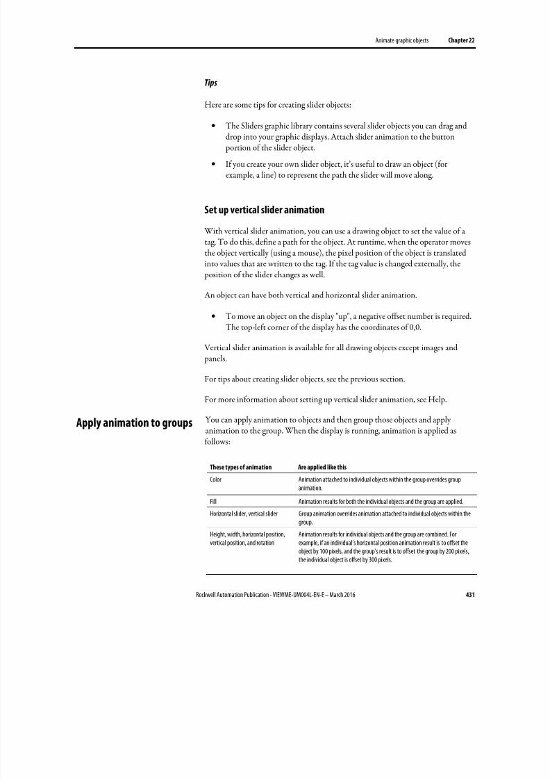
8/17/2019 FactoryTalk® View Machine Edition User's Guide
http://slidepdf.com/reader/full/factorytalk-view-machine-edition-users-guide 431/587
Animate graphic objects Chapter 22
Rockwell Automation Publication - VIEWME-UM004L-EN-E – March 2016 431
Tips
Here are some tips for creating slider objects:
•
The Sliders graphic library contains several slider objects you can drag anddrop into your graphic displays. Attach slider animation to the button portion of the slider object.
• If you create your own slider object, it’s useful to draw an object (forexample, a line) to represent the path the slider will move along.
Set up vertical slider animation
With vertical slider animation, you can use a drawing object to set the value of a
tag. To do this, define a path for the object. At runtime, when the operator movesthe object vertically (using a mouse), the pixel position of the object is translatedinto values that are written to the tag. If the tag value is changed externally, the position of the slider changes as well.
An object can have both vertical and horizontal slider animation.
• To move an object on the display "up", a negative offset number is required.The top-left corner of the display has the coordinates of 0,0.
Vertical slider animation is available for all drawing objects except images and
panels.
For tips about creating slider objects, see the previous section.
For more information about setting up vertical slider animation, see Help.
You can apply animation to objects and then group those objects and applyanimation to the group. When the display is running, animation is applied asfollows:
These types of animation Are applied like this
Color Animation attached to individual objects within the group overrides groupanimation.
Fill Animation results for both the individual objects and the group are applied.
Horizontal slider, vertical slider Group animation overrides animation attached to individual objects within thegroup.
Height, width, horizontal position,vertical position, and rotation
Animation results for individual objects and the group are combined. Forexample, if an individual’s horizontal position animation result is to offset theobject by 100 pixels, and the group’s result is to offset the group by 200 pixels,the individual object is offset by 300 pixels.
Apply animation to groups
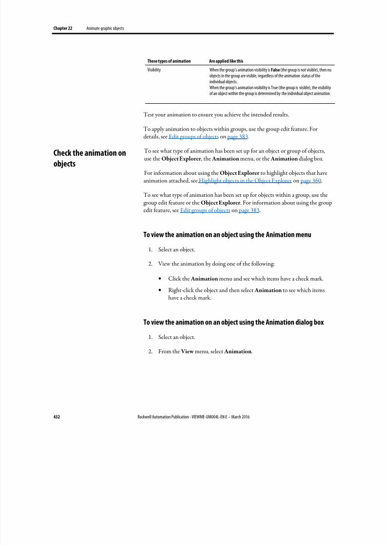
8/17/2019 FactoryTalk® View Machine Edition User's Guide
http://slidepdf.com/reader/full/factorytalk-view-machine-edition-users-guide 432/587
Chapter 22 Animate graphic objects
432 Rockwell Automation Publication - VIEWME-UM004L-EN-E – March 2016
These types of animation Are applied like this
Visibility When the group’s animation visibility is False (the group is not visible), then noobjects in the group are visible, regardless of the animation status of theindividual objects.When the group’s animation visibility is True (the group is visible), the visibilityof an object within the group is determined by the individual object animation.
Test your animation to ensure you achieve the intended results.
To apply animation to objects within groups, use the group edit feature. Fordetails, see Edit groups of objects on page 383.
To see what type of animation has been set up for an object or group of objects,use the Object Explorer , the Animation menu, or the Animation dialog box.
For information about using the Object Explorer to highlight objects that haveanimation attached, see Highlight objects in the Object Explorer on page 360.
To see what type of animation has been set up for objects within a group, use thegroup edit feature or the Object Explorer . For information about using the groupedit feature, see Edit groups of objects on page 383.
To view the animation on an object using the Animation menu
1. Select an object.
2. View the animation by doing one of the following:
• Click the Animation menu and see which items have a check mark.
• Right-click the object and then select Animation to see which itemshave a check mark.
To view the animation on an object using the Animation dialog box
1.
Select an object.
2. From the View menu, select Animation.
Check the animation on
objects
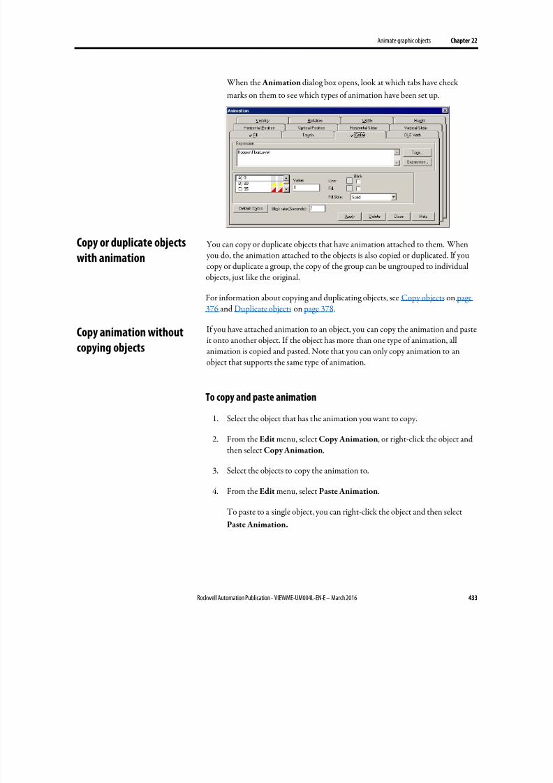
8/17/2019 FactoryTalk® View Machine Edition User's Guide
http://slidepdf.com/reader/full/factorytalk-view-machine-edition-users-guide 433/587
Animate graphic objects Chapter 22
Rockwell Automation Publication - VIEWME-UM004L-EN-E – March 2016 433
When the Animation dialog box opens, look at which tabs have check
marks on them to see which types of animation have been set up.
You can copy or duplicate objects that have animation attached to them. When you do, the animation attached to the objects is also copied or duplicated. If youcopy or duplicate a group, the copy of the group can be ungrouped to individualobjects, just like the original.
For information about copying and duplicating objects, see Copy objects on page376 and Duplicate objects on page 378.
If you have attached animation to an object, you can copy the animation and pasteit onto another object. If the object has more than one type of animation, allanimation is copied and pasted. Note that you can only copy animation to an
object that supports the same type of animation.
To copy and paste animation
1.
Select the object that has the animation you want to copy.
2.
From the Edit menu, select Copy Animation, or right-click the object and
then select Copy Animation.
3.
Select the objects to copy the animation to.
4.
From the Edit menu, select Paste Animation.
To paste to a single object, you can right-click the object and then select
Paste Animation.
Copy or duplicate objectswith animation
Copy animation without
copying objects

8/17/2019 FactoryTalk® View Machine Edition User's Guide
http://slidepdf.com/reader/full/factorytalk-view-machine-edition-users-guide 434/587
Chapter 22 Animate graphic objects
434 Rockwell Automation Publication - VIEWME-UM004L-EN-E – March 2016
FactoryTalk View global objects allow you to link the appearance and behavior ofa graphic object to multiple copies of that object. When the original base object isupdated, the changes are automatically applied to all the copies of the object. Forinformation about creating base objects, see Use global objects on page 469.
The copies of the object are called reference objects, and they have the same properties as the original base object. If desired, you can assign unique animationto the reference object. For information about creating reference objects, seeCreate reference objects on page 471.
The LinkAnimation property determines whether the reference object uses thebase object’s animation.
To set up animation for a reference object
1. Double-click the reference object to open the Property Panel.
2. Select the LinkAnimation property setting to use:
• Do not link — allows you to set up separate animation for thereference object.
• Link with expressions — the reference object uses the animation andtags or expressions assigned to the base object.
• Link without expressions — allows you to use only the types of
animation set up for the base object, but assign different tags orexpressions to the reference object.
3. If you selected Do not link ,or Link without expressions, set up animationfor the object using the methods described in this chapter.
For more information about setting up link properties and working with referenceobjects, see Set up reference objects’ link properties on page 473.
Set up animation for global
objects
8/17/2019 FactoryTalk® View Machine Edition User's Guide
http://slidepdf.com/reader/full/factorytalk-view-machine-edition-users-guide 435/587
Rockwell Automation Publication - VIEWME-UM004L-EN-E – March 2016 435
Chapter 23
Use expressions
This chapter describes:
• The types of expression components
• Use the Expression editor
• Which editors use expressions
•
Format expressions• Use tag names and tag placeholders with expressions
• Use constants
• Use operators
• Use math, security, and language functions
• Use if-then-else logic in expressions
• The evaluation order of operators
• Use write expressions
Sometimes the data you gather from devices is meaningful only when you:
• Compare it to other values.
• Combine it with other values.
• Create a cause-effect relationship with other values.
Expressions allow you to create mathematical or logical combinations of data thatreturn more meaningful values. Depending on the components used in theexpression, the value returned can be in the form of a numeric value, a true/false
value, or a text string.
Expressions that result in floating-point values
If an expression results in a floating-point value but an integer value is required,the floating-point value is rounded.
For information about how values are rounded, see How values are rounded on page 100.
About expressions
8/17/2019 FactoryTalk® View Machine Edition User's Guide
http://slidepdf.com/reader/full/factorytalk-view-machine-edition-users-guide 436/587
Chapter 23 Use expressions
436 Rockwell Automation Publication - VIEWME-UM004L-EN-E – March 2016
Expression components
Expressions can be built from:
•
Tag values
• Tag placeholders
• Constants
• Arithmetic, relational, logical, and bitwise operators
• Mathematical and security functions
• If-then-else logic
Tags, arithmetic operators, bitwise operators, and mathematical functions such as
SQRT (square root) return numeric values.
Relational and logical operators return true/false values. The security functionCurrentUserHasCode( x ) also returns a true/false value.
The security function CurrentUserName( ) returns a string value. The languagefunction CurrentLanguage( ) returns a string value.
Expressions that use if-then-else logic can return numeric values, true/false values,or text strings, depending on how they are structured. These are called conditionalexpressions because the result of the expression depends on whether the Ifstatement is true or false. When the If statement evaluates to true, the result isdefined by the Then statement. When the If statement is false, the result is definedby the Else statement.
The Objects 5 Screen Demo sample application contains many examples ofexpressions. For example, see the alarm trigger expressions in the Alarm Setup editor.
To create an expression, you can:
• Type it directly in the Tag or expression column, for any connection thataccepts expressions, or in the Expression box (for animation).
•
Open the Expression editor, and then create the expression in the editor.
Use the Expression editor versus typing expressions directly
Once you are familiar with expression syntax, you might find it quicker to createshort expressions by typing them directly in the Tag or expression column.
Use the Expression editor
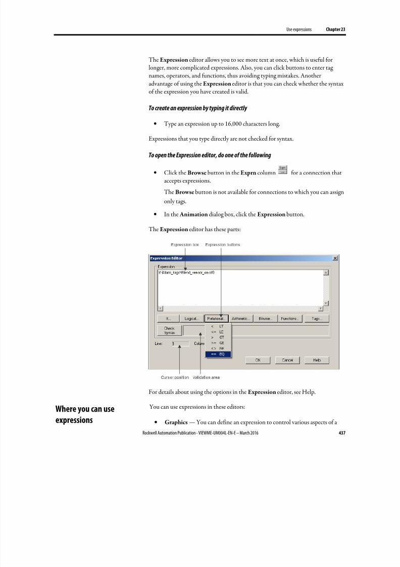
8/17/2019 FactoryTalk® View Machine Edition User's Guide
http://slidepdf.com/reader/full/factorytalk-view-machine-edition-users-guide 437/587
Use expressions Chapter 23
Rockwell Automation Publication - VIEWME-UM004L-EN-E – March 2016 437
The Expression editor allows you to see more text at once, which is useful forlonger, more complicated expressions. Also, you can click buttons to enter tagnames, operators, and functions, thus avoiding typing mistakes. Anotheradvantage of using the Expression editor is that you can check whether the syntaxof the expression you have created is valid.
To create an expression by typing it directly
• Type an expression up to 16,000 characters long.
Expressions that you type directly are not checked for syntax.
To open the Expression editor, do one of the following
•
Click the Browse button in the Exprn column for a connection thataccepts expressions.
The Browse button is not available for connections to which you can assign
only tags.
• In the Animation dialog box, click the Expression button.
The Expression editor has these parts:
For details about using the options in the Expression editor, see Help.
You can use expressions in these editors:
• Graphics — You can define an expression to control various aspects of a
Where you can use
expressions
8/17/2019 FactoryTalk® View Machine Edition User's Guide
http://slidepdf.com/reader/full/factorytalk-view-machine-edition-users-guide 438/587
Chapter 23 Use expressions
438 Rockwell Automation Publication - VIEWME-UM004L-EN-E – March 2016
graphic object’s appearance. For more information about assigningexpressions to graphic objects, see Use expressions to manipulate tag values on page 370.
You can also use expressions to attach animation to graphic objects. Formore information, see Animate graphic objects on page 417.
• Global Connections — You can use expressions to remotely control whento open and print displays, as well as the date and time to show. For moreinformation, see Set up global connections on page 111.
• Alarm Setup — When setting up alarms, you can use expressions for alarmtriggers, and with some of the connections that silence and acknowledgealarms. For more information, see Set up alarms on page 119.
• Information Setup — You can use expressions to determine when to show
information messages. For more information, see Use information messages on page 485.
• Macros — You can use expressions in macros to assign values to tags. Formore information, see Use macros to assign values to tags on page 517.
You can format expressions so they are easier to read. However, do not let tagnames, function names, or function arguments span more than one line.
When formatting expressions, you can use line returns and multiple spaces.
Enclose strings in quotes. The string can contain any character, and can include
spaces.
Example: Format an expression
To format this if-then-else statement, you can align the Else with the appropriateIf, so the logic is easy to understand:
if (tag1 > tag2) then 0else if (tag1 > tag3) then 2else 4
Or you can condense it to the following:
if (tag1 > tag2) then 0 else if (tag1 > tag3) then 2 else 4
A tag name can be included as part of an expression or can stand alone as theentire expression.
To supply a tag name, do one of the following:
• Type a tag name.
Format expressions
Use tag names and tag
placeholders
8/17/2019 FactoryTalk® View Machine Edition User's Guide
http://slidepdf.com/reader/full/factorytalk-view-machine-edition-users-guide 439/587
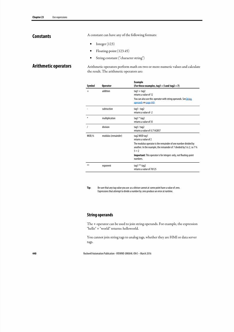
8/17/2019 FactoryTalk® View Machine Edition User's Guide
http://slidepdf.com/reader/full/factorytalk-view-machine-edition-users-guide 440/587
Chapter 23 Use expressions
440 Rockwell Automation Publication - VIEWME-UM004L-EN-E – March 2016
A constant can have any of the following formats:
• Integer (123)
•
Floating-point (123.45)
• String constant ("character string")
Arithmetic operators perform math on two or more numeric values and calculatethe result. The arithmetic operators are:
Symbol Operator
Example
(For these examples, tag1 = 5 and tag2 = 7)
+ addition tag1 + tag2returns a value of 12
You can also use this operator with string operands. See String
operands on page 440.
- subtraction tag1 - tag2returns a value of -2
* multiplication tag1 * tag2returns a value of 35
/ division tag1 / tag2returns a value of 0.7142857
MOD,% modulus (remainder) tag2 MOD tag1returns a value of 2
The modulus operator is the remainder of one number divided byanother. In the example, the remainder of 7 divided by 5 is 2; so 7 %5 = 2
Important: This operator is for integers only, not floating-pointnumbers.
** exponent tag1 ** tag2returns a value of 78125
Tip: Be sure that any tag value you use as a divisor cannot at some point have a value of zero.Expressions that attempt to divide a number by zero produce an error at runtime.
String operands
The + operator can be used to join string operands. For example, the expression"hello" + "world" returns: helloworld.
You cannot join string tags to analog tags, whether they are HMI or data servertags.
Constants
Arithmetic operators
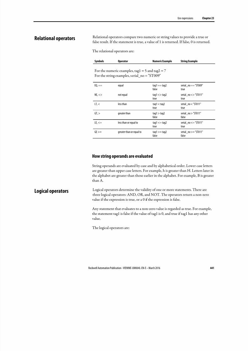
8/17/2019 FactoryTalk® View Machine Edition User's Guide
http://slidepdf.com/reader/full/factorytalk-view-machine-edition-users-guide 441/587
Use expressions Chapter 23
Rockwell Automation Publication - VIEWME-UM004L-EN-E – March 2016 441
Relational operators compare two numeric or string values to provide a true orfalse result. If the statement is true, a value of 1 is returned. If false, 0 is returned.
The relational operators are:
Symbols Operator Numeric Example String Example
For the numeric examples, tag1 = 5 and tag2 = 7For the string examples, serial_no = "ST009"
EQ, == equal tag1 == tag2false
serial_no == "ST009"true
NE, <> not equal tag1 <> tag2true
serial_no <> "ST011"true
LT, < less than tag1 < tag2
true
serial_no < "ST011"
trueGT, > greater than tag1 > tag2
falseserial_no > "ST011"false
LE, <= less than or equal to tag1 <= tag2true
serial_no <= "ST011"true
GE >= greater than or equal to tag1 >= tag2false
serial_no >= "ST011"false
How string operands are evaluated
String operands are evaluated by case and by alphabetical order. Lower case lettersare greater than upper case letters. For example, h is greater than H. Letters later inthe alphabet are greater than those earlier in the alphabet. For example, B is greaterthan A.
Logical operators determine the validity of one or more statements. There arethree logical operators: AND, OR, and NOT. The operators return a non-zero
value if the expression is true, or a 0 if the expression is false.
Any statement that evaluates to a non-zero value is regarded as true. For example,the statement tag1 is false if the value of tag1 is 0, and true if tag1 has any other
value.
The logical operators are:
Relational operators
Logical operators
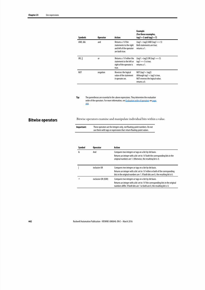
8/17/2019 FactoryTalk® View Machine Edition User's Guide
http://slidepdf.com/reader/full/factorytalk-view-machine-edition-users-guide 442/587
Chapter 23 Use expressions
442 Rockwell Automation Publication - VIEWME-UM004L-EN-E – March 2016
Symbols Operator Action
Example
(For these examples,
tag1 = 5 and tag2 = 7)
AND, && and Returns a 1 if the
statements to the rightand left of the operatorare both true.
(tag1 < tag2) AND (tag1 == 5)
Both statements are true;returns a 1.
OR, || or Returns a 1 if either thestatement to the left orright of the operator istrue.
(tag1 > tag2) OR (tag1 == 5)tag1 == 5 is true;returns a 1.
NOT negation Reverses the logicalvalue of the statementit operates on.
NOT (tag1 < tag2)Although tag1 < tag2 is true,NOT reverses the logical value;returns a 0.
Tip: The parentheses are essential in the above expressions. They determine the evaluationorder of the operators. For more information, see Evaluation order of operators on page444.
Bitwise operators examine and manipulate individual bits within a value.
Important: These operators are for integers only, not floating-point numbers. Do notuse them with tags or expressions that return floating-point values.
Symbol Operator Action
& And Compares two integers or tags on a bit-by-bit basis.
Returns an integer with a bit set to 1 if both the corresponding bits in theoriginal numbers are 1. Otherwise, the resulting bit is 0.
| inclusive OR Compares two integers or tags on a bit-by-bit basis.
Returns an integer with a bit set to 1 if either or both of the correspondingbits in the original numbers are 1. If both bits are 0, the resulting bit is 0.
^ exclusive OR (XOR) Compares two integers or tags on a bit-by-bit basis.Returns an integer with a bit set to 1 if the corresponding bits in the originalnumbers differ. If both bits are 1 or both are 0, the resulting bit is 0.
Bitwise operators
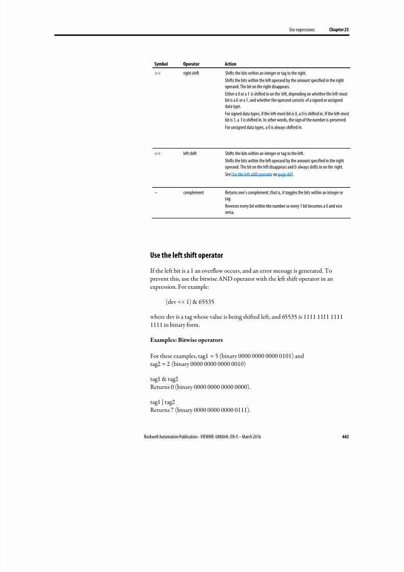
8/17/2019 FactoryTalk® View Machine Edition User's Guide
http://slidepdf.com/reader/full/factorytalk-view-machine-edition-users-guide 443/587
Use expressions Chapter 23
Rockwell Automation Publication - VIEWME-UM004L-EN-E – March 2016 443
Symbol Operator Action
>> right shift Shifts the bits within an integer or tag to the right.
Shifts the bits within the left operand by the amount specified in the right
operand. The bit on the right disappears.Either a 0 or a 1 is shifted in on the left, depending on whether the left-mostbit is a 0 or a 1, and whether the operand consists of a signed or unsigneddata type.
For signed data types, if the left-most bit is 0, a 0 is shifted in. If the left-mostbit is 1, a 1 is shifted in. In other words, the sign of the number is preserved.
For unsigned data types, a 0 is always shifted in.
<< left shift Shifts the bits within an integer or tag to the left.
Shifts the bits within the left operand by the amount specified in the rightoperand. The bit on the left disappears and 0 always shifts in on the right.
See Use the left shift operator on page 443.
~ complement Returns one’s complement; that is, it toggles the bits within an integer ortag.
Reverses every bit within the number so every 1 bit becomes a 0 and viceversa.
Use the left shift operator
If the left bit is a 1 an overflow occurs, and an error message is generated. To prevent this, use the bitwise AND operator with the left shift operator in anexpression. For example:
(dev << 1) & 65535
where dev is a tag whose value is being shifted left, and 65535 is 1111 1111 11111111 in binary form.
Examples: Bitwise operators
For these examples, tag1 = 5 (binary 0000 0000 0000 0101) andtag2 = 2 (binary 0000 0000 0000 0010)
tag1 & tag2Returns 0 (binary 0000 0000 0000 0000).
tag1 | tag2Returns 7 (binary 0000 0000 0000 0111).

8/17/2019 FactoryTalk® View Machine Edition User's Guide
http://slidepdf.com/reader/full/factorytalk-view-machine-edition-users-guide 444/587
Chapter 23 Use expressions
444 Rockwell Automation Publication - VIEWME-UM004L-EN-E – March 2016
tag1 ^ tag2Returns 7 (binary 0000 0000 0000 0111).
tag1 >> 1
Returns 2 (binary 0000 0000 0000 0010).
tag1 << 1Returns 10 (binary 0000 0000 0000 1010).
~ tag1Returns -6 (binary 1111 1111 1111 1010).
Expressions with more than one operator are evaluated in this order:
• Operators in parentheses are evaluated first.
1.
Therefore, to change the order of precedence, use parentheses.
• The operator with the highest precedence is evaluated next.
• When two operators have equal precedence, they are evaluated from left toright.
Operators are evaluated in this order:
Evaluation order Symbols
1 (highest) ( )
2 NOT
~
3 *
/
MOD, %
**
AND, &&
&
>>
<<
4 +
-OR, ||
|
^
5 (lowest) EQ, ==
NE, <>
LT, <
GT, >
LE, <=
GE, >=
Evaluation order of
operators

8/17/2019 FactoryTalk® View Machine Edition User's Guide
http://slidepdf.com/reader/full/factorytalk-view-machine-edition-users-guide 445/587
Use expressions Chapter 23
Rockwell Automation Publication - VIEWME-UM004L-EN-E – March 2016 445
Examples: Evaluation order
For these examples, tag1 = 5, tag2 = 7, and tag3 = 10.
_____________________________
(tag1 > tag2) AND (tag1 < tag3)
is evaluated in this sequence:
1. tag1 > tag2 = 0
2. tag1 < tag3 = 1
3. 0 AND 1 = 0
The expression evaluates to 0 (false).
_____________________________
tag1 > tag2 AND tag3
is evaluated in this sequence:
1.
tag2 AND tag3 = 1
2. tag1 > 1 = 1
The expression evaluates to 1 (true).
_____________________________
NOT tag1 AND tag2 > tag3 ** 2
is evaluated in this sequence:
1. NOT tag1 = 0
2.
0 AND tag2 = 0
3. tag3 ** 2 = 100
4. 0 > 100 = 0
The expression evaluates to 0 (false).
Use math functions to calculate the square root, log (natural or base 10), ortrigonometry ratios (in radians or degrees) of a tag.
Mathematical functions

8/17/2019 FactoryTalk® View Machine Edition User's Guide
http://slidepdf.com/reader/full/factorytalk-view-machine-edition-users-guide 446/587
Chapter 23 Use expressions
446 Rockwell Automation Publication - VIEWME-UM004L-EN-E – March 2016
This function Returns this value
SQRT (expression) The square root of the expression
LOG (expression) The natural log of the expression
LOG10 (expression) The base ten log of the expression
SIN (expression) The sine of the expression in radians
COS (expression) The cosine of the expression in radians
TAN (expression) The tangent of the expression in radians
ARCSIN (expression) The arc sine of the expression in radians
ARCCOS (expression) The arc cosine of the expression in radians
ARCTAN (expression The arc tangent of the expression in radians
SIND (expression) The sine of the expression in degrees
COSD (expression) The cosine of the expression in degrees
TAND (expression) The tangent of the expression in degrees
ARCSIND (expression) The arc sine of the expression in degrees
ARCCOSD (expression) The arc cosine of the expression in degrees
ARCTAND (expression) The arc tangent of the expression in degrees
Use security functions to control access to your application.
These functions allow you to determine a user’s identity or security rights in orderto limit access to the application based on these criteria.
This function Returns this value
CurrentUserName( ) A string containing the name of the current user.
This function is case sensitive. All RSView 3.20 and earlier user names useuppercase letters.
CurrentUserHasCode( Security Code Letters)
True (1) if any of the s pecified security codes have been assigned to the user;false (0) if not.
If checking multiple security codes, do not type a space between the securitycode letters.
For example: CurrentUserHasCode(ABP) returns the value 1 if the user has beenassigned one or more of the specified codes.
CurrentUserHasGroup("Group Name" ) True (1) if the current user is assigned to the specified group configured in
FactoryTalk Directory; false (0) if not.
This function is only supported in 8.0 and later versions of FactoryTalk MEapplications.
The group name must be enclosed with double quotes.
For example, CurrentUserHasGroup("Group A") returns the value 1 if the user hasbeen assigned to Group A.
For more information about setting up security for your application, see Set upsecurity on page 175.
Security functions

8/17/2019 FactoryTalk® View Machine Edition User's Guide
http://slidepdf.com/reader/full/factorytalk-view-machine-edition-users-guide 447/587
Use expressions Chapter 23
Rockwell Automation Publication - VIEWME-UM004L-EN-E – March 2016 447
For an example of using the CurrentUserHasCode( x ) function, see To assign
visibility animation to the shutdown button on page 193.
For examples of using the CurrentUserName( ) function, see To assign visibilityanimation to the Goto display button on page 193.
The language function shows you which language your application is currentlyusing.
You can show the current language in a string display, or use it in expressions togenerate language-specific messages for your users.
This function Returns this value
CurrentLanguage( ) RFC1766 name of the current runtime language.
The RFC1766 name is a standard way of representing a language using the format:languagecode-Country/RegionCode
where languagecode is a lowercase two-letter code and Country/ RegionCode is an
uppercase two-letter code.
For example, U.S. English is en-US.
For more information about setting up languages for your application, see Set uplanguage switching on page 199. For a list of RFC1766 names, see RFC1766names on page 557.
Language switching alarm, information, and local messages in
FactoryTalk View ME Station 4.00
FactoryTalk View 5.00 and later provides direct support for switching messagelanguages at runtime.
For applications that will run in FactoryTalk View ME Station version 4.00, usethe CurrentLanguage( ) expression function to specify message offsets in theinformation message file. In the file, divide your messages into sections for eachlanguage. To do this, set up trigger value offsets for series of messages in the Alarm
Setup editor, information message files, and local message files.
Export the text strings in the Alarm Setup editor and message files for translation.Then paste the translated strings into the editor and original message files, andassign each string the correct trigger value. For information about exporting textfor translation, see Set up language switching on page 199.
Language function
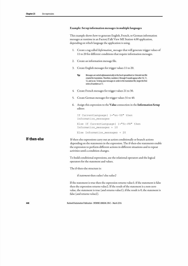
8/17/2019 FactoryTalk® View Machine Edition User's Guide
http://slidepdf.com/reader/full/factorytalk-view-machine-edition-users-guide 448/587
Chapter 23 Use expressions
448 Rockwell Automation Publication - VIEWME-UM004L-EN-E – March 2016
Example: Set up information messages in multiple languages
This example shows how to generate English, French, or German informationmessages at runtime in an FactoryTalk View ME Station 4.00 application,depending on which language the application is using.
1. Create a tag called Information_messages that will generate trigger values of
11 to 20 for different conditions that require information messages.
2. Create an information message file.
3. Create English messages for trigger values 11 to 20.
Tip: Messages are sorted alphanumerically in the Excel spreadsheet or Unicode text filecreated for translation. Therefore, numbers 2 through 9 would appear after 10, 11,12, and so on. To keep your messages in order in the translation file, begin the firstseries of numbers at 11.
4. Create French messages for trigger values 21 to 30.
5. Create German messages for trigger values 31 to 40.
6. Assign this expression to the Value connection in the Information Setup editor:
If CurrentLanguage( )="en-US" then
Information_messages
Else If CurrentLanguage( )="fr-FR" thenInformation_messages + 10
Else Information_messages + 20
If-then-else expressions carry out an action conditionally or branch actionsdepending on the statements in the expression. The if-then-else statements enablethe expression to perform different actions in different situations and to repeatactivities until a condition changes.
To build conditional expressions, use the relational operators and the logicaloperators for the statement and values.
The if-then-else structure is:
if statement then value1 else value2
If the statement is true then the expression returns value1; if the statement is falsethen the expression returns value2. If the result of the statement is a non-zero value, the statement is true (and returns value1); if the result is 0, the statement isfalse (and returns value2).
If-then-else
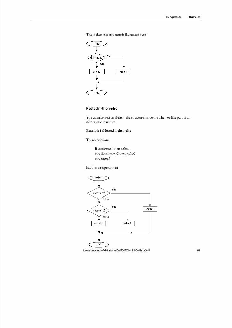
8/17/2019 FactoryTalk® View Machine Edition User's Guide
http://slidepdf.com/reader/full/factorytalk-view-machine-edition-users-guide 449/587
Use expressions Chapter 23
Rockwell Automation Publication - VIEWME-UM004L-EN-E – March 2016 449
The if-then-else structure is illustrated here.
Nested if-then-else
You can also nest an if-then-else structure inside the Then or Else part of anif-then-else structure.
Example 1: Nested if-then-else
This expression:
if statement1 then value1
else if statement2 then value2 else value3
has this interpretation:
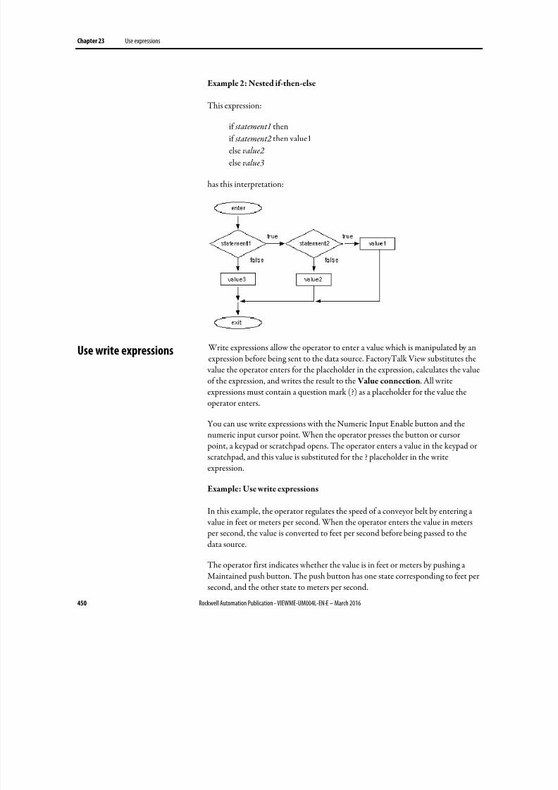
8/17/2019 FactoryTalk® View Machine Edition User's Guide
http://slidepdf.com/reader/full/factorytalk-view-machine-edition-users-guide 450/587
Chapter 23 Use expressions
450 Rockwell Automation Publication - VIEWME-UM004L-EN-E – March 2016
Example 2: Nested if-then-else
This expression:
if statement1 then
if statement2 then value1
else value2
else value3
has this interpretation:
Write expressions allow the operator to enter a value which is manipulated by anexpression before being sent to the data source. FactoryTalk View substitutes the
value the operator enters for the placeholder in the expression, calculates the valueof the expression, and writes the result to the Value connection. All writeexpressions must contain a question mark (?) as a placeholder for the value theoperator enters.
You can use write expressions with the Numeric Input Enable button and thenumeric input cursor point. When the operator presses the button or cursor point, a keypad or scratchpad opens. The operator enters a value in the keypad orscratchpad, and this value is substituted for the ? placeholder in the writeexpression.
Example: Use write expressions
In this example, the operator regulates the speed of a conveyor belt by entering a value in feet or meters per second. When the operator enters the value in meters per second, the value is converted to feet per second before being passed to thedata source.
The operator first indicates whether the value is in feet or meters by pushing aMaintained push button. The push button has one state corresponding to feet persecond, and the other state to meters per second.
Use write expressions
8/17/2019 FactoryTalk® View Machine Edition User's Guide
http://slidepdf.com/reader/full/factorytalk-view-machine-edition-users-guide 451/587
Use expressions Chapter 23
Rockwell Automation Publication - VIEWME-UM004L-EN-E – March 2016 451
Then the operator presses the Numeric Input Enable button and enters the valuefor the conveyor speed in a numeric pop-up keypad. The ? character in the writeexpression is the placeholder for the value the operator enters.
To set up the Maintained push button
1. In the Maintained Push Button Properties dialog box, in the States tab,set up these states:
• State 0 — Value: 0, Caption: Feet/S
• State 1 — Value: 1, Caption: Meters/S
2. In the Connections tab, assign a digital tag called Feet_or_meters to the
Value connection (either an HMI tag or a data server tag).
To set up the Numeric Input Enable button
1. In the Numeric Input Enable Properties dialog box, in the Label tab, typethe caption Enter conveyor speed .
2. In the Connections tab, assign a tag called Conveyor_speed to the Value
connection.
3.
Assign this expression to the Optional Exp connection:
if Feet_or_meters == 0 then
?
else
? * 3.281
FactoryTalk View writes the result of the expression to the Conveyor_speed tag atthe data source.

8/17/2019 FactoryTalk® View Machine Edition User's Guide
http://slidepdf.com/reader/full/factorytalk-view-machine-edition-users-guide 452/587
Chapter 23 Use expressions
452 Rockwell Automation Publication - VIEWME-UM004L-EN-E – March 2016
8/17/2019 FactoryTalk® View Machine Edition User's Guide
http://slidepdf.com/reader/full/factorytalk-view-machine-edition-users-guide 453/587
Rockwell Automation Publication - VIEWME-UM004L-EN-E – March 2016 453
Chapter 24
Use embedded variables
This chapter describes:
• The types of embedded variables
• Where you can create embedded variables
• Create embedded variables
•
Embedded variable syntax• How embedded variables are updated at runtime
• How embedded variables are shown at runtime
Embedded variables allow you to show values that change dynamically at runtime.You can use embedded variables in the text captions on graphic objects, in the titlebar of On Top displays, and in message text. You can use multiple embedded variables in the same caption or message.
For example, you could embed a tag value and the time variable in a local message.At runtime when the local message is shown, it is updated to reflect the tag’scurrent value as the value changes. The time is also updated as the time changes.
You can also use literal strings and constants in embedded variables, or acombination of both variable and literal strings and numbers.
Embedded variables can consist of:
• Numeric (analog or digital) tags, including both HMI and data server tags
• Literal numbers (constants)
• String tags, including both HMI and data server tags
•
Literal strings (static text)
• Tag placeholders. For information about tag placeholders, see Use tag placeholders on page 461.
• The time
• The date
About embedded variables
8/17/2019 FactoryTalk® View Machine Edition User's Guide
http://slidepdf.com/reader/full/factorytalk-view-machine-edition-users-guide 454/587
Chapter 24 Use embedded variables
454 Rockwell Automation Publication - VIEWME-UM004L-EN-E – March 2016
You can create embedded variables in these editors:
• Graphics — Use this editor to insert embedded variables in the captionsfor graphic objects. For graphic objects with multiple states, you can insertdifferent embedded variables in each state’s caption.
You can also use embedded variables in the title bar for On Top displays.
For information about specific graphic objects, see Set up graphic objects on
page 391. For information about On Top displays, see On Top displays on
page 314.
• Local Messages — Use this editor to insert embedded variables in localmessages.
For more information about local messages, see Use local messages on page
328.
• Information Messages — Use this editor to insert embedded variables ininformation messages.
For more information about information messages, see Use information
messages on page 485.
• Alarm Setup — Use this editor to insert embedded variables in alarmmessages.
For more information about alarms, see Set up alarms on page 119.
To create an embedded variable in a graphic object’s caption
1. Open the graphic object’s Properties dialog box.
2. Click the tab containing the Caption box.
The Caption box is on the Label tab or the States tab, depending on the
type of object.
For text objects, use the Text box on the General tab.
3. Click Insert Variable.
4. Click the type of variable to insert.
5. Fill in the options in the dialog box that opens. For details about theoptions, see Help.
Where you can create
embedded variables
Create embedded variables
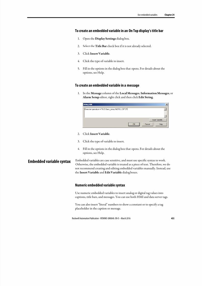
8/17/2019 FactoryTalk® View Machine Edition User's Guide
http://slidepdf.com/reader/full/factorytalk-view-machine-edition-users-guide 455/587
Use embedded variables Chapter 24
Rockwell Automation Publication - VIEWME-UM004L-EN-E – March 2016 455
To create an embedded variable in an On Top display’s title bar
1. Open the Display Settings dialog box.
2.
Select the Title Bar check box if it is not already selected.
3. Click Insert Variable.
4. Click the type of variable to insert.
5. Fill in the options in the dialog box that opens. For details about theoptions, see Help.
To create an embedded variable in a message
1. In the Message column of the Local Messages, Information Messages, or Alarm Setup editor, right click and then click Edit String .
2.
Click Insert Variable.
3. Click the type of variable to insert.
4. Fill in the options in the dialog box that opens. For details about theoptions, see Help.
Embedded variables are case sensitive, and must use specific syntax to work.Otherwise, the embedded variable is treated as a piece of text. Therefore, we donot recommend creating and editing embedded variables manually. Instead, usethe Insert Variable and Edit Variable dialog boxes.
Numeric embedded variable syntax
Use numeric embedded variables to insert analog or digital tag values intocaptions, title bars, and messages. You can use both HMI and data server tags.
You can also insert "literal" numbers to show a constant or to specify a tag placeholder in the caption or message.
Embedded variable syntax

8/17/2019 FactoryTalk® View Machine Edition User's Guide
http://slidepdf.com/reader/full/factorytalk-view-machine-edition-users-guide 456/587
Chapter 24 Use embedded variables
456 Rockwell Automation Publication - VIEWME-UM004L-EN-E – March 2016
Numeric embedded variables use this syntax:
/*LN:# Tag_name Fill_character DP:#*/
where
• L (optional) indicates it is a literal (constant) number. This symbol prevents
a tag read. If you type a tag placeholder for the Tag_name, the value of the
placeholder is substituted from the parameter file or global object parameterdefinition.
• N indicates it’s a numeric embedded variable.
• # indicates the number of digits.
• Tag_name is the tag to show; you can also type a literal number or tag
placeholder here.
• Fill_character is the fill character to use: NOFILL, ZEROFILL, or
SPACEFILL.
• # indicates the number of decimal places.
Examples: Numeric embedded variable syntax
To show the current value of a tag called Oven_temp, with 3 digits, no decimal places, and no fill character, type this:
/*N:3 Oven_temp NOFILL DP:0*/
To show the constant 48, with 3 decimal places and 2 zeroes to the left of thenumber (for a total length of 8 digits including the decimal), type this:
/*LN:8 48 ZEROFILL DP:3*/
At runtime the numeric embedded variable would look like this: 0048.000.
String embedded variable syntax
Use string embedded variables to insert string tag values into captions, title bars,and messages.
You can also insert "literal" strings of static text. For example, you can type a wordor phrase, a tag placeholder, or a number. To control how constant numbers areshown, use a literal numeric variable rather than a string variable.
String embedded variables use this syntax:
/*LS:-# Tag_name SHOWSTAR*/

8/17/2019 FactoryTalk® View Machine Edition User's Guide
http://slidepdf.com/reader/full/factorytalk-view-machine-edition-users-guide 457/587
Use embedded variables Chapter 24
Rockwell Automation Publication - VIEWME-UM004L-EN-E – March 2016 457
where
• L (optional) indicates it is a literal (static) string. This symbol prevents a tag
read. If you type a tag placeholder for the Tag_name, the value of the
placeholder is substituted from the parameter file or global object parameterdefinition. The value cannot contain spaces.
• S indicates it’s a string embedded variable.
• - (optional). A minus sign (-) before the # indicates that if the string is
longer than the fixed number of characters, the right-most characters will beshown.
• # indicates the number of characters if you select a fixed number of
characters; type 0 if you don’t want to use a fixed number.
•
Tag_name is the tag to show; you can also type a literal string or tag placeholder here. The string cannot contain spaces.
• SHOWSTAR (optional) specifies that if the string is longer than the fixed
number of characters, an asterisk (*) will be shown to indicate the string istruncated. If you use the minus sign (-), the asterisk will be shown as thefirst character at the left end of the string. Otherwise, the asterisk will beshown as the last character at the right end of the string.
Examples: String embedded variable syntax
To show the current value of a string tag called Blower_status, with a fixed length
of 20 characters, you would type this:
/*S:20 Blower_status*/
To show the literal string Oven temperature, type this:
/*LS:20 "Oven temperature"*/
To show the literal string 36.5, type this:
/*LS:3 36.5*/
To assign the tag placeholder #1, without a fixed string length, type this:
/*S:0 #1*/
To show the value of the string tag Conveyor_message, with a fixed length of 40,showing the right-most characters, with an asterisk to indicate if the message istruncated, type this:
/*S:-40 Conveyor_message SHOWSTAR*/
8/17/2019 FactoryTalk® View Machine Edition User's Guide
http://slidepdf.com/reader/full/factorytalk-view-machine-edition-users-guide 458/587
Chapter 24 Use embedded variables
458 Rockwell Automation Publication - VIEWME-UM004L-EN-E – March 2016
Time and date embedded variable syntax
Use time and date embedded variables to insert the current time or date into
captions, title bars, and messages
Time and date embedded variables use this syntax:
/*Time_date_format */
where
Time_date_format uses one of these character sequences:
These characters Specify this format
SD Short date
LD Long date
SDT Short date and time
LDT Long date and time
T Time
TSD Time and short date
TLD Time and long date
Example: Time and date embedded variable syntax
To show the time followed by the short date, you would type this:
/*TSD*/
A space is placed between the time and date when the embedded variable is shownat runtime.
At runtime, this is how embedded variables are shown and updated:
• Graphic objects and title bars — When a display containing a graphicobject or title bar that uses an embedded variable is open, the value of theembedded variable is updated whenever a new tag value is read from the
data source. For time and date embedded variables, the time and date areupdated as the system time and date change.
• Local messages — When a display containing a local message display objectis open, and the message the object is showing contains an embedded variable, the value of the embedded variable is updated whenever a new tag value is read from the data source. For time and date embedded variables,the time and date are updated as the system time and date change.
• Information messages — The value of the embedded variable is read whenthe information message is first shown. It is not updated after that.
How embedded variables
are updated at runtime
8/17/2019 FactoryTalk® View Machine Edition User's Guide
http://slidepdf.com/reader/full/factorytalk-view-machine-edition-users-guide 459/587
Use embedded variables Chapter 24
Rockwell Automation Publication - VIEWME-UM004L-EN-E – March 2016 459
If the message is printed, it is printed using the value the variable had when
the message was first shown. This value is retained if you shut down and
restart the application.
•
Alarm messages — The value of the embedded variable is read when thealarm occurs, and is shown in the message associated with the alarm. It isnot updated after that.
If the message is printed, it is printed using the value the variable had when
the alarm first occurred. This value is retained if you shut down and restart
the application.
If there is no valid data available for the embedded variable, the variable is replaced with question marks (?). This could occur when a display first opens and the datahas not arrived yet, or when there is a problem that prevents communication with
the data source.
If a string or numeric embedded variable has been set up but no tag has beenassigned, the embedded variable is replaced with asterisks (*).
Numeric embedded variables
The value shown for a numeric embedded variable depends on whether the tag value is a floating-point number or an integer. Integer values are shown as is.Floating-point values are rounded to fit the specified number of digits for the
variable.
For example, if the variable is set up to show 6 digits, 1234.56 is rounded to1234.6. 1234.44 is rounded to 1234.4. The decimal counts as one of the digits.
For more information about how values are rounded, see How values are rounded on page 100.
If the tag value, including the decimal point and minus sign, contains more digitsthan specified for the variable, the numeric variable is replaced with asterisks.
For example, if the variable is set up to show 6 digits, and the tag value is -123456,the variable will be replaced with asterisks.
Literal numbers are shown using the same rules as numeric tag values.
Number formats
The numeric variable uses the number format of the current application language.For example, if the application language uses a comma for the decimal symbol, thenumeric variable uses a comma for the decimal symbol.
How embedded variables
are shown at runtime
8/17/2019 FactoryTalk® View Machine Edition User's Guide
http://slidepdf.com/reader/full/factorytalk-view-machine-edition-users-guide 460/587
Chapter 24 Use embedded variables
460 Rockwell Automation Publication - VIEWME-UM004L-EN-E – March 2016
For information about using multiple languages, see Set up language switching on page 199.
String embedded variables
For string embedded variables that do not use a fixed number of characters, theentire string tag value is shown, unless a null character is read. Nothing after a nullcharacter is shown.
If a fixed number of characters is used, the variable shows the value of the tag up tothe number of characters specified, unless a null character is encountered beforethe specified length. Nothing is shown after a null character. If necessary, spacesare used to make up the required number of characters.
Null characters have a hex value of 0. The null character indicates the end of stringinput. It does not add to the actual string length.
If the string is longer than the specified number of characters, it is truncated to fitthe number of characters. If the SHOWSTAR option is used, an asterisk (*)replaces the first or last character shown. If the embedded variable is set up toshow right-most characters, excess characters are truncated at the left end of thestring and the asterisk (if used) appears at the left. Otherwise, the right-mostcharacters are truncated and the asterisk (if used) appears at the right.
Literal strings are shown using the same rules as string tag values.
Time and date embedded variables
For embedded variables that show both the time and the date, a space is placedbetween the time and date when the embedded variable is shown at runtime.
Time and date formats
Time and date embedded variables use the time and date formats for the currentapplication language. For example, if you specify the short date format, at runtime
the display uses the short date format that the application language uses.
For information about using multiple languages, see Set up language switching on page 199.
8/17/2019 FactoryTalk® View Machine Edition User's Guide
http://slidepdf.com/reader/full/factorytalk-view-machine-edition-users-guide 461/587
Rockwell Automation Publication - VIEWME-UM004L-EN-E – March 2016 461
Chapter 25
Use parameters and global objects
This chapter describes:
• Use tag placeholders and parameter files or lists
• Create tag placeholders
• Create parameter files and parameter lists
•
Use global objects• Create global object displays and base objects
• Create, set up, and delete reference objects
• Use global object parameters
• Adding controller instruction faceplates that connect to Logix5000 processors
The topics in this chapter describe features of FactoryTalk View Studio that canhelp you set up your applications more quickly by reusing similar groups of objectsand graphic displays.
• Tag placeholders, parameter lists, and parameter files allow you to use thesame graphic display with different sets of tags.
• Global objects allow you to use multiple instances of the same graphic objectand make changes to all of the objects at once.
• Global object parameters allow you to assign different sets of tags todifferent copies of the object without breaking the link to the base object,thus preserving the ability to update all copies of the object at once.
• Controller instruction faceplates provide pre-configured graphic displays
that interact with the instructions in Logix5000 processors.
Use a tag placeholder to mark where you want to insert a tag name or some part ofa tag name at runtime. A tag placeholder is a crosshatch character (#) followed bya number from 1 to 500.
FactoryTalk View Machine Edition uses three methods for replacing a tag placeholder with a tag name:
• Parameter files
Use tag placeholders
8/17/2019 FactoryTalk® View Machine Edition User's Guide
http://slidepdf.com/reader/full/factorytalk-view-machine-edition-users-guide 462/587
Chapter 25 Use parameters and global objects
462 Rockwell Automation Publication - VIEWME-UM004L-EN-E – March 2016
• Parameter lists
• Global object parameters
To use the same graphic display with different sets of tags, use tag placeholders with parameter files or parameter lists. Using tag placeholders can be quicker thanduplicating a display and setting up the objects in it to use a different set of tags,especially when the display uses a lot of tags. Using parameter files or parameterlists also reduces the size of the runtime application file.
You can use tag placeholders wherever you would normally assign a tag to anobject, including in expressions and embedded variables. You can also use tag placeholders in the expressions you create to animate objects.
Tag placeholders can provide a way to use one graphic display to represent a
number of similar operations. For example, suppose you are creating displays for a plant that cans corn and peas. The machinery used in both processes is identical.Instead of creating two displays and specifying corn-related tags in one display and pea-related tags in another, you can create one display and not specify any tagnames. Where a tag name is required, type a tag placeholder.
Use parameter files or parameter lists to specify which tags to substitute for which placeholders when a display opens at runtime. For information about using parameter files, see Create parameter files on page 464. For information aboutusing parameter lists, see Create parameter lists on page 467.
You can also use tag placeholders with global objects. You can assign tag
placeholders to the connections for base objects, and to connections for referenceobjects with the LinkConnections property set to False. For more informationabout global objects, see Use global objects on page 469.
You can use tag placeholders in:
• The graphic display that opens when the application is first run. Specify thegraphic display to open, and the parameter file or parameter list to use withit, in the Startup editor.
• Graphic displays that are opened using Goto display buttons. Specify thegraphic display to open, and the parameter file or parameter list to use withit, when you set up the button.
• Graphic displays that are opened using display list selectors. Specify thegraphic displays to open, and the parameter files or parameter lists to use with them, when you set up the display list selector.
• The graphic display that opens when a logout button is pressed.
• The graphic display specified in the Project Settings Runtime tab whenauto logout is enabled.

8/17/2019 FactoryTalk® View Machine Edition User's Guide
http://slidepdf.com/reader/full/factorytalk-view-machine-edition-users-guide 463/587
Use parameters and global objects Chapter 25
Rockwell Automation Publication - VIEWME-UM004L-EN-E – March 2016 463
• Displays specified in the Display tab of the Global Connections editor.
Steps for using tag placeholders
Follow these steps to use tag placeholders with parameter files or parameter lists:
1.
In the Graphics editor, create graphic objects and assign tag placeholders tothe objects.
2.
If you are using parameter files, create parameter files in the Parameters editor for each set of tags that the display will use. In the parameter files,specify which tags to substitute for which placeholders.
3.
In the Graphics editor, create Goto display buttons, logout buttons, or
display list selectors for opening the display containing tag placeholders.Specify the appropriate parameter files in the graphic object’s dialog box.
To use parameter lists, specify the tags for the lists in the dialog box.
4.
If the startup display uses tag placeholders, in the Startup editor, specify the parameter file to use with the startup display. To use a parameter list, specifythe tags for the list in the Startup editor.
For information about the Startup editor, see Create runtime applications
on page 223.
5.
If auto logout is enabled, you have the option of opening a display on
logout. Specify the appropriate parameter file on the Runtime tab of the
Project Settings dialog box. To use a parameter list, specify the tags for thelist in the Project Settings dialog box.
For information about the Project Settings editor, see Help.
6. If the displays that will be changed remotely by global connections use parameters, specify the parameter file or parameter list in the Display tab of
the Global Connections editor.
For information on global connections, see Set up global connections on
page 111.
8/17/2019 FactoryTalk® View Machine Edition User's Guide
http://slidepdf.com/reader/full/factorytalk-view-machine-edition-users-guide 464/587
Chapter 25 Use parameters and global objects
464 Rockwell Automation Publication - VIEWME-UM004L-EN-E – March 2016
Create tag placeholders
A tag placeholder is the crosshatch character (#) followed by a number.
The tag placeholder can replace any part of a tag name, including folder names.For example, you could create a parameter file specifying that the tag placeholder#1=Folder1. You could assign the folder and a tag name to a graphic object’sconnection: #1\Tag1.
You can create tag placeholders in:
• The Connections tab of an object’s Properties dialog box.
• The Connections tab of the Property Panel.
• The Expression box in the Animation dialog box.
• A global object’s Parameter Definitions dialog box.
• Anywhere that you can insert an embedded variable. For information aboutembedded variables, see Use embedded variables on page 453.
To create a tag placeholder
• Type the cross-hatch character followed by a number from 1 to 500 (nospace in between). For example, #1.
Create parameter files
The parameter file specifies which tags to substitute for the placeholders on thedisplay, by assigning one tag to each unique placeholder on the display. Create a parameter file for each set of tags that you want to use with the same graphicdisplay.
At runtime, the tag values that are shown depend on which parameter file is used when the display opens. When you open the display, the tags specified in the parameter file replace the tag placeholders.
Parameters can replace any portion of a tag address. For example, you can use parameters to replace folder names.
Parameter files can list up to 500 tag placeholders. Use them when a large numberof tag placeholders are needed for a display. The text format of a parameter fileallows you to see and edit the placeholders easily. When copying displays from oneapplication to another, the related parameter files must also be copied.
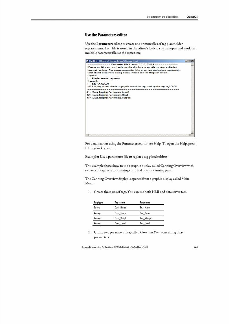
8/17/2019 FactoryTalk® View Machine Edition User's Guide
http://slidepdf.com/reader/full/factorytalk-view-machine-edition-users-guide 465/587
Use parameters and global objects Chapter 25
Rockwell Automation Publication - VIEWME-UM004L-EN-E – March 2016 465
Use the Parameters editor
Use the Parameters editor to create one or more files of tag placeholder
replacements. Each file is stored in the editor’s folder. You can open and work onmultiple parameter files at the same time.
For details about using the Parameters editor, see Help. To open the Help, pressF1 on your keyboard.
Example: Use a parameter file to replace tag placeholders
This example shows how to use a graphic display called Canning Overview withtwo sets of tags, one for canning corn, and one for canning peas.
The Canning Overview display is opened from a graphic display called MainMenu.
1. Create these sets of tags. You can use both HMI and data server tags.
Tag type Tag name Tag name
String Corn_Name Pea_Name
Analog Corn_Temp Pea_Temp
Analog Corn_Weight Pea_Weight
Analog Corn_Level Pea_Level
2. Create two parameter files, called Corn and Peas, containing these
parameters:
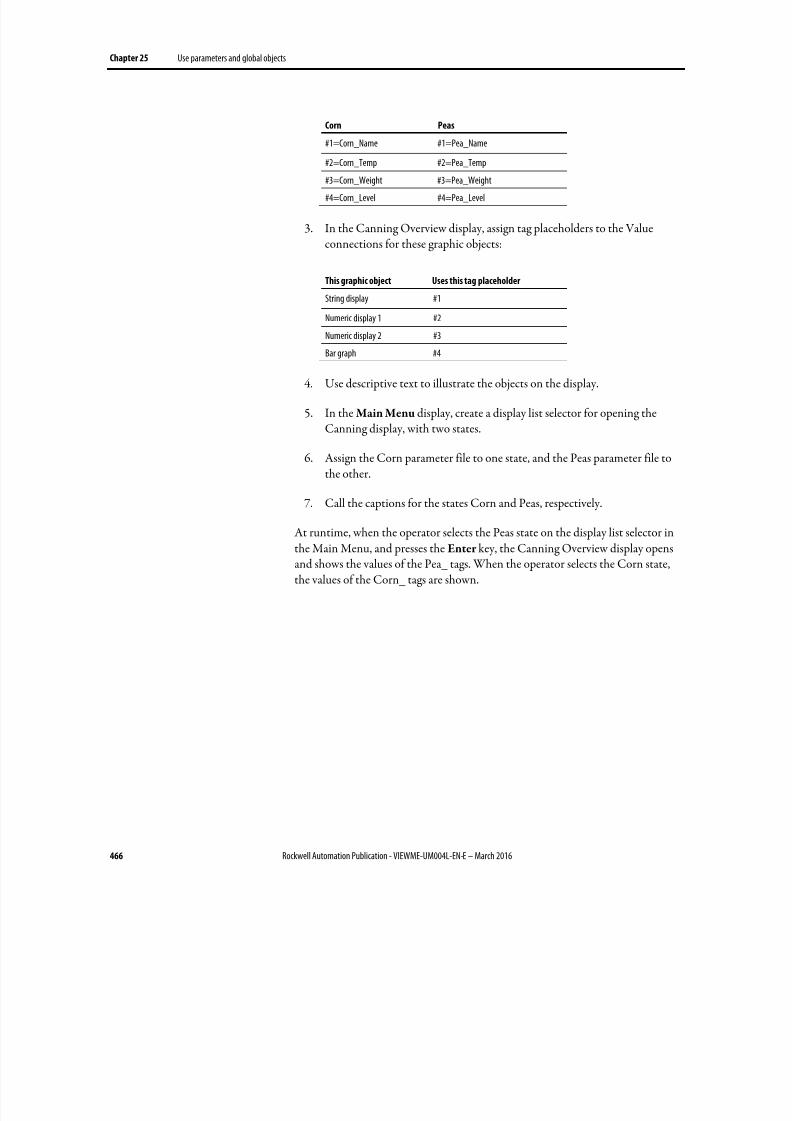
8/17/2019 FactoryTalk® View Machine Edition User's Guide
http://slidepdf.com/reader/full/factorytalk-view-machine-edition-users-guide 466/587
Chapter 25 Use parameters and global objects
466 Rockwell Automation Publication - VIEWME-UM004L-EN-E – March 2016
Corn Peas
#1=Corn_Name #1=Pea_Name
#2=Corn_Temp #2=Pea_Temp
#3=Corn_Weight #3=Pea_Weight
#4=Corn_Level #4=Pea_Level
3. In the Canning Overview display, assign tag placeholders to the Valueconnections for these graphic objects:
This graphic object Uses this tag placeholder
String display #1
Numeric display 1 #2
Numeric display 2 #3
Bar graph #4
4. Use descriptive text to illustrate the objects on the display.
5. In the Main Menu display, create a display list selector for opening theCanning display, with two states.
6. Assign the Corn parameter file to one state, and the Peas parameter file tothe other.
7. Call the captions for the states Corn and Peas, respectively.
At runtime, when the operator selects the Peas state on the display list selector inthe Main Menu, and presses the Enter key, the Canning Overview display opensand shows the values of the Pea_ tags. When the operator selects the Corn state,the values of the Corn_ tags are shown.
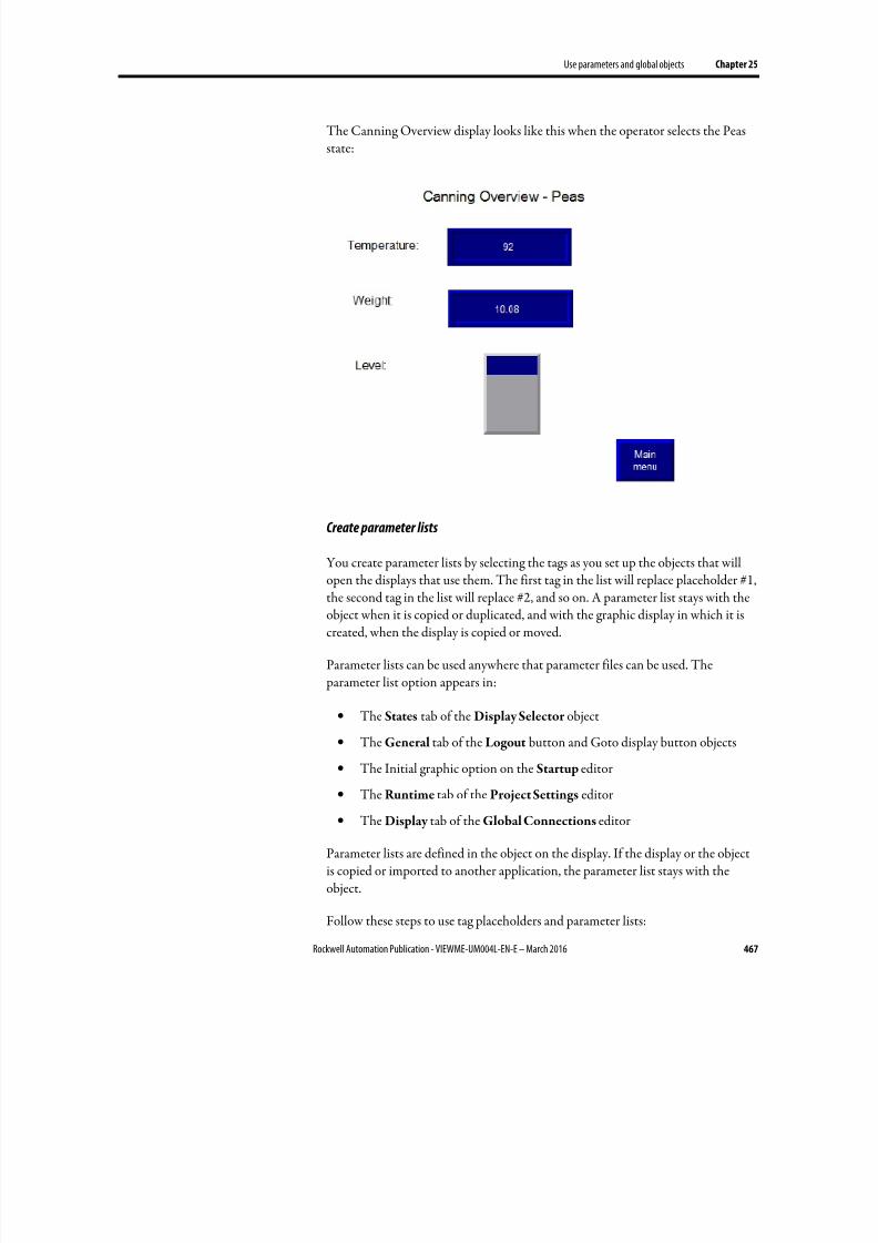
8/17/2019 FactoryTalk® View Machine Edition User's Guide
http://slidepdf.com/reader/full/factorytalk-view-machine-edition-users-guide 467/587
Use parameters and global objects Chapter 25
Rockwell Automation Publication - VIEWME-UM004L-EN-E – March 2016 467
The Canning Overview display looks like this when the operator selects the Peasstate:
Create parameter lists
You create parameter lists by selecting the tags as you set up the objects that will
open the displays that use them. The first tag in the list will replace placeholder #1,the second tag in the list will replace #2, and so on. A parameter list stays with theobject when it is copied or duplicated, and with the graphic display in which it iscreated, when the display is copied or moved.
Parameter lists can be used anywhere that parameter files can be used. The parameter list option appears in:
• The States tab of the Display Selector object
• The General tab of the Logout button and Goto display button objects
•
The Initial graphic option on the Startup editor• The Runtime tab of the Project Settings editor
• The Display tab of the Global Connections editor
Parameter lists are defined in the object on the display. If the display or the objectis copied or imported to another application, the parameter list stays with theobject.
Follow these steps to use tag placeholders and parameter lists:
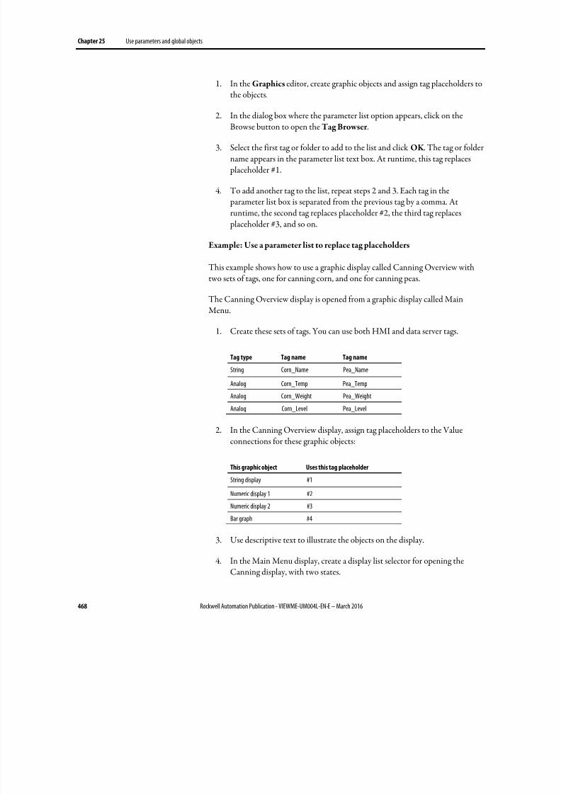
8/17/2019 FactoryTalk® View Machine Edition User's Guide
http://slidepdf.com/reader/full/factorytalk-view-machine-edition-users-guide 468/587
Chapter 25 Use parameters and global objects
468 Rockwell Automation Publication - VIEWME-UM004L-EN-E – March 2016
1. In the Graphics editor, create graphic objects and assign tag placeholders tothe objects.
2. In the dialog box where the parameter list option appears, click on the
Browse button to open the Tag Browser .
3. Select the first tag or folder to add to the list and click OK . The tag or foldername appears in the parameter list text box. At runtime, this tag replaces placeholder #1.
4. To add another tag to the list, repeat steps 2 and 3. Each tag in the parameter list box is separated from the previous tag by a comma. Atruntime, the second tag replaces placeholder #2, the third tag replaces placeholder #3, and so on.
Example: Use a parameter list to replace tag placeholders
This example shows how to use a graphic display called Canning Overview withtwo sets of tags, one for canning corn, and one for canning peas.
The Canning Overview display is opened from a graphic display called MainMenu.
1. Create these sets of tags. You can use both HMI and data server tags.
Tag type Tag name Tag name
String Corn_Name Pea_Name
Analog Corn_Temp Pea_Temp
Analog Corn_Weight Pea_Weight
Analog Corn_Level Pea_Level
2. In the Canning Overview display, assign tag placeholders to the Valueconnections for these graphic objects:
This graphic object Uses this tag placeholder
String display #1
Numeric display 1 #2
Numeric display 2 #3
Bar graph #4
3. Use descriptive text to illustrate the objects on the display.
4. In the Main Menu display, create a display list selector for opening theCanning display, with two states.

8/17/2019 FactoryTalk® View Machine Edition User's Guide
http://slidepdf.com/reader/full/factorytalk-view-machine-edition-users-guide 469/587
Use parameters and global objects Chapter 25
Rockwell Automation Publication - VIEWME-UM004L-EN-E – March 2016 469
5. In the first state, choose the parameter list option and select the Corn parameter tags from the Tag Browser in this order: Corn_Name,Corn_Temp, Corn_Weight, Corn_Level. In the second state, do the samefor the Peas tags.
6. Call the captions for the states Corn and Peas, respectively.
At runtime, when the operator selects the Peas state on the display list selector inthe Main Menu, and presses the Enter key, the Canning Overview display opensand shows the values of the Pea_ tags. When the operator selects the Corn state,the values of the Corn_ tags are displayed.
Parameter passing
You can use parameter files or parameter lists to pass (carry forward) parameters
from one display to other related displays that open from it. To carry the same parameter forward to subsequent displays, assign the same tag placeholder (forexample, #1), instead of a tag name in the parameter list or parameter file field ofthe object in the related display.
Example: Use a parameter list to replace tag placeholders in linked displays
This example uses PIDE faceplate displays to demonstrate parameter passing.
The main, or first level display, is called MAIN. It has a Goto display button thatopens a Logix_PIDE faceplate display. The faceplate has a Goto display button
that opens a Trend faceplate.
In the Main display, the Goto display button has the parameter list option on theGeneral tab selected, and a structure tag name, with a shortcut, selected from theTag Browser to represent #1: {::[PLC1]Program:Fermenter_Temp.Tank_PIDE01}, for example.
When the button is pressed, the Logix_PIDE faceplate opens. The objects on thefaceplate have been set up to read the tags in the structure: #1.CV, #1.SP, and soon. The objects replace the parameter #1 with the structure tag name and thenderive their values from the structure elements they have been set up to read.
To carry the same parameters forward another level, the Goto display button onthe Logix_PIDE faceplate display has the parameter list option on its General tabselected, and the parameter {#1} typed in. When this button is pressed, the Trendfaceplate opens, and its objects in turn replace their #1 parameters with the samestructure tag name, and read their values from the appropriate elements.
FactoryTalk View global objects allow you to link the appearance and behavior ofa graphic object to multiple copies of that object. When you update the originalobject, the changes are automatically applied to all the copies of the object.
Use global objects
8/17/2019 FactoryTalk® View Machine Edition User's Guide
http://slidepdf.com/reader/full/factorytalk-view-machine-edition-users-guide 470/587
Chapter 25 Use parameters and global objects
470 Rockwell Automation Publication - VIEWME-UM004L-EN-E – March 2016
You create global objects in global object displays, in the Global Objects folder ofthe Explorer window. The objects you create in a global object display are calledbase objects.
You can copy or drag base objects into standard graphic displays. The copiedobject is called a reference object. You can copy a global object into any number ofgraphic displays, and multiple times into the same graphic display.
Global object displays (.ggfx) are stored in the default folder\Users\Public\Public Documents\RSView Enterprise\ME\HMI
projects\ Application Name\Global Objects
where Application Name is the name of your application.
Steps for setting up global objects
Follow these steps to set up global objects:
1. In the Graphics editor, create a global object display. For more information,see the next section.
2. Create graphic objects in the global object display. These are the baseobjects. Set up their appearance, animation, and connections.
3. Copy or drag base objects into a standard graphic display. The copied
objects are reference objects. For more information, see Create referenceobjects on page 471.
4. Edit the link properties of the reference objects as desired. For moreinformation, see Set up reference objects’ link properties on page 473.
Create global object displays and base objects
You can create a global object display in the Global Objects folder, or create agraphic display in the Displays folder and then add the display to the Global
Objects folder. You can also add library displays to the Global Objects folder.
The objects you create in the global object displays are called base objects.
To create a global object display
1. In the Graphics folder, right-click Global Objects, and then select New .
2. Create graphic objects on the display. These are the base objects.

8/17/2019 FactoryTalk® View Machine Edition User's Guide
http://slidepdf.com/reader/full/factorytalk-view-machine-edition-users-guide 471/587
Use parameters and global objects Chapter 25
Rockwell Automation Publication - VIEWME-UM004L-EN-E – March 2016 471
Tip: You cannot use ActiveX objects as base objects. You cannot convert objects to wallpaper inthe global object display.
For information about creating graphic objects, see Use graphic objects on
page 335.
3. From the File menu, select Save, or click the Save tool .
4. In the Component name box, type a name for the display, and then clickOK .
The display is added to the list in the Global Objects folder.
To add a display or library to the Global Objects folder
1. In the Explorer window, in the Graphics folder, right-click the Global
Objects icon.
2. Select Add Component Into Application.
3. Browse to and select the display or library to add, and then click Open.
The display is copied into the Global Objects folder, and given the file
extension .ggfx.
Any ActiveX objects are deleted. All other objects are converted to base
objects.
Tip: If you delete, remove, or rename a global object display, you break the links between thebase objects on the display and their reference objects. For more information aboutbreaking links, see Help.
Create reference objects
FactoryTalk View global objects allow you to link the appearance and behavior ofa graphic object to multiple copies of that object. When the original base object isupdated, the changes are automatically applied to all the copies of the object. Thecopies of the base object are called reference objects.
You can copy or drag base objects into standard graphic displays. Each copiedobject becomes a reference object. You can also copy, drag, and duplicate referenceobjects that you have already created to create more copies of the base object.

8/17/2019 FactoryTalk® View Machine Edition User's Guide
http://slidepdf.com/reader/full/factorytalk-view-machine-edition-users-guide 472/587
Chapter 25 Use parameters and global objects
472 Rockwell Automation Publication - VIEWME-UM004L-EN-E – March 2016
Tip: Base objects can be group objects. This provides powerful template capabilities. When youadd or remove objects from the base object group, all the reference objects areautomatically updated.
If desired, you can assign unique connections, animation, and size to the referenceobject.
To create a reference object
1. Copy an object from a global object display to a standard graphic display.
2. To assign unique connections, animation, or size to the object, double-clickthe object to open the Property Panel.
3. For information about using the Property Panel, see Use the Property
Panel on page 363.
You can also create reference objects by adding a global object display to theDisplays folder. All the objects in the new display are reference objects.
To add a global object display to the Displays folder
1. In the Explorer window, in the Graphics folder , right-click the Displaysicon.
2.
Select Add Component Into Application.
3.
Browse to and select the global object display to add, and then click Open.
The display is copied into the Displays folder, and given the file
extension .gfx. All the objects are converted to reference objects.
To edit a reference object’s base object
1. Right-click the reference object, and then select Edit Base Object.
2. The global object display containing the base object opens, with the objectselected.
3. Make your changes to the base object.
4. All reference objects linked to the base object are updated.
To view the changes to the reference object, close the display containing thereference object, and then reopen it. Or, toggle the object’s LinkSize property onand off.
8/17/2019 FactoryTalk® View Machine Edition User's Guide
http://slidepdf.com/reader/full/factorytalk-view-machine-edition-users-guide 473/587
Use parameters and global objects Chapter 25
Rockwell Automation Publication - VIEWME-UM004L-EN-E – March 2016 473
Set up reference objects’ link properties
FactoryTalk View global objects allow you to link the appearance and behavior of
a graphic object to multiple copies of that object. When the original base object isupdated, the changes are automatically applied to all the copies of the object.
The copies of the object are called reference objects, and they have the same properties as the original base object. If desired, you can assign unique size,connections, and animation to the reference object.
To assign unique properties to the reference object, use the Property Panel to editthe following properties for the reference object:
• LinkSize — select False to set up the height and width separately for thereference object. If LinkSize is set to true, when you try to resize the
reference object, it will snap back to its linked size.
• LinkConnections — select False to set up connections separately for thereference object. Whether you use the base object’s connections, or set upseparate connections, the tags used count towards the tag limit for thedisplay.
You can assign tag placeholders to the connections for base objects, and to
connections for reference objects with the LinkConnections property set
to False.
• LinkAnimation—select Do not link to set up separate animation for the
reference object. To use the animation set up for the base object but assigndifferent expressions to the reference object, select Link without
expressions.
If you select Link with expressions, the reference object uses the animation
and expressions assigned to the base object.
Reference objects also have a property called LinkBaseObject , which specifies the
name and location of the base object to which the reference object is linked. Youcannot edit the LinkBaseObject property.
To change a reference object’s link properties
1. Double-click the object to open the Property Panel.
2. Make your changes to the link properties.
3. Specify the new size, connections, or animation for the object.
For information about resizing objects, see Resize objects on page 379.

8/17/2019 FactoryTalk® View Machine Edition User's Guide
http://slidepdf.com/reader/full/factorytalk-view-machine-edition-users-guide 474/587
Chapter 25 Use parameters and global objects
474 Rockwell Automation Publication - VIEWME-UM004L-EN-E – March 2016
For information about assigning connections to objects, see Assign tags andexpressions to an object’s connections on page 364.
For information about assigning animation to objects, see Animate graphic objects
on page 417.
To specify default link properties for reference objects
1. From the Edit menu, select Global Object Defaults.
2. Specify the new default values.
3. Click OK .
The defaults are used for any new reference objects you create. You can still
edit the properties for individual objects separately.
To break the link to a base object
• Right-click the reference object, and then click Break Link .
The reference object becomes a regular object. You can edit all of its
properties. However, you cannot restore the connection to the base object.
Delete the base object
If you delete a base object or a global object display containing base objects, anyreference objects that are linked to the deleted base objects are broken. A brokenreference object is displayed as a red square with an X through it. You cannot editbroken reference objects.
To repair a broken reference object
• Recreate the base object with the same object type and name as before, onthe same display as before.
Global object parameters are parameters that you can assign to global objects. Youcan use a global object parameter to assign different tags or sets of tags to eachreference object without breaking the link to the base object. You can then makechanges to the base object and all the associated reference objects at the same time.
Use global object parameters when more than one instance of a global object isused on a display. For example, the Logix_PIDE global object display contains agrouped object composed of other grouped objects. The objects’ connections areset up with tags and expressions that use values from a set of Logix5000 tags. When you create multiple reference objects from this base object, each reference
Use global objectparameters
8/17/2019 FactoryTalk® View Machine Edition User's Guide
http://slidepdf.com/reader/full/factorytalk-view-machine-edition-users-guide 475/587
Use parameters and global objects Chapter 25
Rockwell Automation Publication - VIEWME-UM004L-EN-E – March 2016 475
object can use a different set of Logix5000 tags. The global object parameters youassign to the base object allow you to do this, because you are using a placeholderinstead of a specific backing tag (a backing tag is a path to a folder of tags; it is alsoknown as a structured tag). If you then change, add, or remove a tag or expressionin the base object, the same change is made to all the reference objects.
If you don’t use global object parameters, you can still assign different tags todifferent reference objects by changing the reference object’s LinkConnections property to False and the LinkAnimations property to Link without expressions.
The global object parameter takes the same form as a regular parameter: #1, where
1 can be any number from 1 to 500. The parameter can be the placeholder for an
individual tag or for a folder of tags. For example, #1 could be a placeholder for the path to the folder containing the PIDE tags assigned to the global object.
When you set up the base object, specify the global object parameters to use withthe object. You can provide a description of each parameter to remind you oranother application designer of the type of value to assign to the parameter on thereference object. Then assign specific values to each parameter for the referenceobject. You can assign numeric or string constants, tags, or backing tags.
Difference between global object parameters and regular parameters
Global object parameters allow you to assign different values to different instancesof the same placeholder. For example, each reference object on the display might
have the placeholder #1. Using regular parameter files, you could only assign one value to #1, and this would apply to all objects in the graphic display. With globalobject parameters, you can assign a different value to #1 for each object that usesthe placeholder #1.
If a placeholder is defined in a global object parameter for an individual object anddefined in a parameter file, the definition assigned to the object takes precedence.
Use global object parameters with group objects
To use global object parameters with a group object, the parameters are defined atthe group level, not at the level of individual objects. Thus the definition applies toeach object within the group. You can assign as many parameters as desired to thegroup. For example, you might assign #1 to some members of the group and #2 toother members of the group. If you create a global object parameter definition foran object and later group the object, the definition is deleted. In addition, if youcreate a global object parameter definition for a group and then ungroup theobject, the definition is deleted.
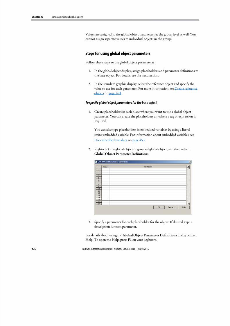
8/17/2019 FactoryTalk® View Machine Edition User's Guide
http://slidepdf.com/reader/full/factorytalk-view-machine-edition-users-guide 476/587
Chapter 25 Use parameters and global objects
476 Rockwell Automation Publication - VIEWME-UM004L-EN-E – March 2016
Values are assigned to the global object parameters at the group level as well. Youcannot assign separate values to individual objects in the group.
Steps for using global object parameters
Follow these steps to use global object parameters:
1.
In the global object display, assign placeholders and parameter definitions tothe base object. For details, see the next section.
2. In the standard graphic display, select the reference object and specify the value to use for each parameter. For more information, see Create referenceobjects on page 471.
To specify global object parameters for the base object
1. Create placeholders in each place where you want to use a global object parameter. You can create the placeholders anywhere a tag or expression isrequired.
You can also type placeholders in embedded variables by using a literal
string embedded variable. For information about embedded variables, see
Use embedded variables on page 453.
2.
Right-click the global object or grouped global object, and then selectGlobal Object Parameter Definitions.
3. Specify a parameter for each placeholder for the object. If desired, type adescription for each parameter.
For details about using the Global Object Parameter Definitions dialog box, seeHelp. To open the Help, press F1 on your keyboard.
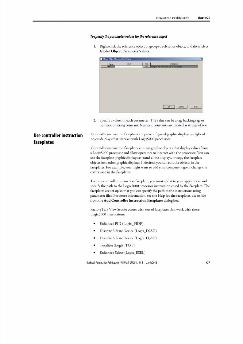
8/17/2019 FactoryTalk® View Machine Edition User's Guide
http://slidepdf.com/reader/full/factorytalk-view-machine-edition-users-guide 477/587
Use parameters and global objects Chapter 25
Rockwell Automation Publication - VIEWME-UM004L-EN-E – March 2016 477
To specify the parameter values for the reference object
1. Right-click the reference object or grouped reference object, and then selectGlobal Object Parameter Values.
2. Specify a value for each parameter. The value can be a tag, backing tag, ornumeric or string constant. Numeric constants are treated as strings of text.
Controller instruction faceplates are pre-configured graphic displays and globalobject displays that interact with Logix5000 processors.
Controller instruction faceplates contain graphic objects that display values froma Logix5000 processor and allow operators to interact with the processor. You canuse the faceplate graphic displays as stand-alone displays, or copy the faceplateobjects into other graphic displays. If desired, you can edit the objects in thefaceplates. For example, you might want to add your company logo or change thecolors used in the faceplates.
To use a controller instruction faceplate, you must add it to your application andspecify the path to the Logix5000 processor instructions used by the faceplate. Thefaceplates are set up so that you can specify the path to the instructions using parameter files. For more information, see the Help for the faceplates, accessiblefrom the Add Controller Instruction Faceplates dialog box.
FactoryTalk View Studio comes with sets of faceplates that work with these
Logix5000 instructions:
• Enhanced PID (Logix_PIDE)
• Discrete 2-State Device (Logix_D2SD)
• Discrete 3-State Device (Logix_D3SD)
• Totalizer (Logix_TOT)
• Enhanced Select (Logix_ESEL)
Use controller instruction
faceplates
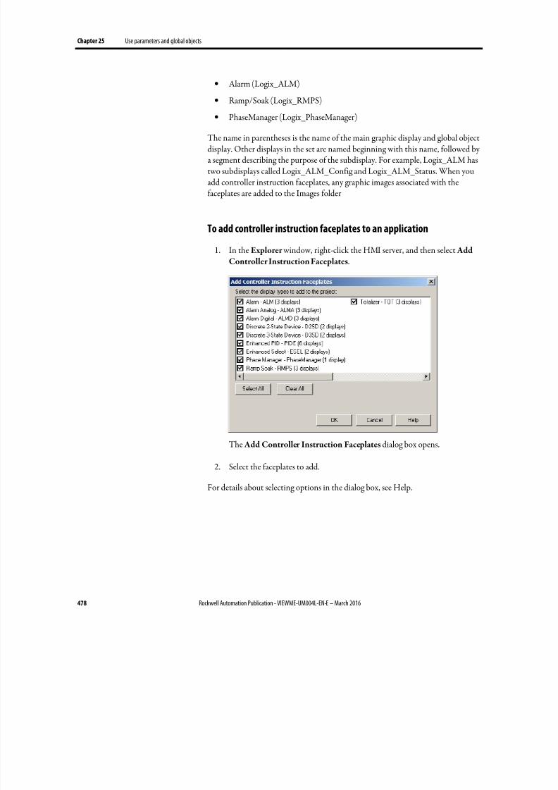
8/17/2019 FactoryTalk® View Machine Edition User's Guide
http://slidepdf.com/reader/full/factorytalk-view-machine-edition-users-guide 478/587
Chapter 25 Use parameters and global objects
478 Rockwell Automation Publication - VIEWME-UM004L-EN-E – March 2016
• Alarm (Logix_ALM)
• Ramp/Soak (Logix_RMPS)
• PhaseManager (Logix_PhaseManager)
The name in parentheses is the name of the main graphic display and global objectdisplay. Other displays in the set are named beginning with this name, followed bya segment describing the purpose of the subdisplay. For example, Logix_ALM hastwo subdisplays called Logix_ALM_Config and Logix_ALM_Status. When youadd controller instruction faceplates, any graphic images associated with thefaceplates are added to the Images folder
To add controller instruction faceplates to an application
1.
In the Explorer window, right-click the HMI server, and then select Add
Controller Instruction Faceplates.
The Add Controller Instruction Faceplates dialog box opens.
2. Select the faceplates to add.
For details about selecting options in the dialog box, see Help.
8/17/2019 FactoryTalk® View Machine Edition User's Guide
http://slidepdf.com/reader/full/factorytalk-view-machine-edition-users-guide 479/587
Rockwell Automation Publication - VIEWME-UM004L-EN-E – March 2016 479
Chapter 26
Set up data logging
This chapter describes:
• Steps for setting up data logging
• Data log files
• Data log models
•
Change the data log model used at runtime• Show data logs using the trend graphic object
• Problems with data logging
Follow these steps to set up data logging:
1. In the Data Log Models editor, set up a data log model that specifies howmany log values to store, the conditions that trigger data logging, where tolog data, and which tags to monitor.
2. In the Startup editor, turn on data logging by selecting the Data logging
check box. Also use this editor to specify the data log model to use atruntime. See Create runtime applications on page 223.
3. In the Graphics editor, create a graphic display containing the trendgraphic object, and set up how the object looks, which tag values to show,the start time, and the time span for the data. Also specify the name of thedata log model to use.
As soon as the application starts running, FactoryTalk View begins logging tag values to the data log files. When the maximum number of data points have beenlogged, the oldest data is deleted to make room for the new data. FactoryTalk
View supplies data from the log files to the trend object for the requested tags andtime span.
The data log files are retained when you restart an application after a shutdown or power loss. You can delete the log files from the runtime computer at applicationstartup.
Use data logging to keep a permanent record of tag data. You can record tag dataas tag values change, or on a periodic basis (for example, every minute).
Steps for setting up data
logging
Data log files
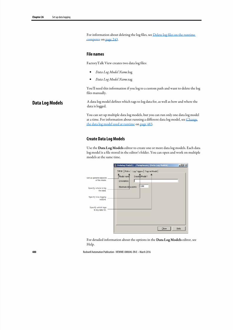
8/17/2019 FactoryTalk® View Machine Edition User's Guide
http://slidepdf.com/reader/full/factorytalk-view-machine-edition-users-guide 480/587
Chapter 26 Set up data logging
480 Rockwell Automation Publication - VIEWME-UM004L-EN-E – March 2016
For information about deleting the log files, see Delete log files on the runtimecomputer on page 243.
File names
FactoryTalk View creates two data log files:
• Data Log Model Name.log
• Data Log Model Name.tag
You’ll need this information if you log to a custom path and want to delete the logfiles manually.
A data log model defines which tags to log data for, as well as how and where thedata is logged.
You can set up multiple data log models, but you can run only one data log modelat a time. For information about running a different data log model, see Changethe data log model used at runtime on page 483.
Create Data Log Models
Use the Data Log Models editor to create one or more data log models. Each data
log model is a file stored in the editor’s folder. You can open and work on multiplemodels at the same time.
For detailed information about the options in the Data Log Models editor, seeHelp.
Data Log Models
8/17/2019 FactoryTalk® View Machine Edition User's Guide
http://slidepdf.com/reader/full/factorytalk-view-machine-edition-users-guide 481/587
Set up data logging Chapter 26
Rockwell Automation Publication - VIEWME-UM004L-EN-E – March 2016 481
Each data log model has a unique name, and an optional description.
You can log a maximum of 1,000,000 points for version 7.00.00 or later, and youcan log 300,000 points for release versions earlier than 7.00.00. The default is
1000. When the maximum number of data points have been logged, the oldestdata is deleted to make room for the new data.
Data storage locations
You can store data log files in any one of these locations:
• On the runtime computer
• On another computer on the network
•
On a memory stick for a MobileView terminal
• On an SD card for aPanelView Plus 7 or PanelView Plus 6 terminal
• On a compact flash card for a PanelView Plus, PanelView Plus Compact, orPanelView Plus CE terminal
If the logging destination is unavailable for any reason, for example, the card isremoved or the network drive becomes unavailable, data logging stops. It does notrestart until you restart the application.
Log to a network location
To log data to a network location, the network drive must be shared, and theruntime computer must be logged in to the same domain as the computer on thenetwork. To do this, the user must have access rights for the domain.
The PanelView Plus 7, PanelView Plus 6, PanelView Plus, PanelView PlusCompact, or PanelView Plus CE terminal cannot be part of a domain. However, you can verify that the user who is logged into the terminal is on a user list that is part of a domain.
For more information about logging in to a Windows domain or authenticating
users, see Log in to the application on page 261.
Data logging methods
There are two methods for triggering data logging. You can set up logging so tag values are logged:
• Periodically (periodic logging)
8/17/2019 FactoryTalk® View Machine Edition User's Guide
http://slidepdf.com/reader/full/factorytalk-view-machine-edition-users-guide 482/587
Chapter 26 Set up data logging
482 Rockwell Automation Publication - VIEWME-UM004L-EN-E – March 2016
• Only when a tag value changes (on-change logging)
Log periodically
Periodic logging is used to take a snapshot of all tag values at a particular point intime. Tag values are logged even if there has been no change.
You cannot change the periodic log rate at runtime.
Log on change
On-change logging is used to log only tags whose values have changed.
For HMI tags, before logging occurs, the change must equal a specified percentageof change in the tag value. The percentage is based on HMI tags’ minimum andmaximum values as set up in the Tags editor. Only the tags that change by thespecified percentage are logged. If you specify a percentage of 0, all changes arelogged.
If a tag does not have a minimum or maximum attribute (for example a data servertag in Logix5000), when you specify on-change logging, all changes are logged forthat tag. You don’t need to specify a percentage.
Use a heartbeat rate
You can also specify a heartbeat rate, to log values at specified times even if no tag
value changes have occurred. The heartbeat ensures that the data in the log file iscurrent. The heartbeat is also a good way to ensure that data logging is workingand acquiring valid data.
The heartbeat cannot be less than the maximum update rate, which is the rate at which data servers send tag values to FactoryTalk View.
If you specify a heartbeat of 0, the heartbeat is not used.
Tags in the data log model
The data log model can contain up to 100 analog or digital tags, including bothHMI and data server tags.
You cannot use string tags, array tags, tag placeholders, parameters, or expressionsin your data log model.
8/17/2019 FactoryTalk® View Machine Edition User's Guide
http://slidepdf.com/reader/full/factorytalk-view-machine-edition-users-guide 483/587
Set up data logging Chapter 26
Rockwell Automation Publication - VIEWME-UM004L-EN-E – March 2016 483
Delete tags from the model
If you delete a tag from the data log model, previously logged data for the tag is notaccessible unless you add the tag back to the model.
Your application can run only one data log model at a time. Follow this procedureto switch data log models.
To run a different data log model
1.
Shut down the application.
2. Start FactoryTalk View Studio and open the application.
3.
In the Startup editor, specify the new data log model.
4. Create the runtime application. See Create runtime applications on page223.
5. Transfer the runtime application to the runtime platform.
For information about transferring applications to:
• A personal computer, see Run applications on a personal computer on page 229.
•
A MobileView, PanelView Plus 7, PanelView Plus 6, PanelView Plus,PanelView Plus Compact, or PanelView Plus CE terminal, see Transferapplications to a MobileView, PanelView Plus 7, PanelView Plus 6,PanelView Plus, PanelView Plus Compact, or PanelView Plus CEterminal on page 247.
6. Run the new application.
You can use the trend graphic object to show the data that you have logged. Atruntime, when the operator opens a graphic display containing a trend, the trendshows values from the data log file for the data log model that is running. The data
log model specifies which data to collect in the data log file.
In addition to showing historical values from the data log file, trends can showcurrent values for the tags in the model. Trends can also show current values fortags or expressions that are not in a data log model. For more information abouttrends, see Set up trends on page 493.
Change the data log model
used at runtime
Show data logs using the
trend graphic object

8/17/2019 FactoryTalk® View Machine Edition User's Guide
http://slidepdf.com/reader/full/factorytalk-view-machine-edition-users-guide 484/587
Chapter 26 Set up data logging
484 Rockwell Automation Publication - VIEWME-UM004L-EN-E – March 2016
Problems with data logging occur under these circumstances:
• When your application starts at runtime, if any of the tags specified in thecurrent data log model do not exist, an error message is sent to FactoryTalkDiagnostics.
• If the data log file is corrupted or invalid, the file is deleted and recreated,and an error message is sent to FactoryTalk Diagnostics.
• If logging to a folder on a networked computer, and the runtime computeris not logged in to the Windows domain of the network computer, the logfolder cannot be created. An error message is sent to FactoryTalkDiagnostics.
• If logging to an invalid path, the log folder cannot be created. An errormessage is sent to FactoryTalk Diagnostics. One of the reasons that the path
might be invalid is that the top-level folder of the path is not shared.• When the application starts, FactoryTalk View checks whether there is disk
space to store the data log model’s data. If there is not enough space, anerror message is sent to FactoryTalk Diagnostics and data logging does notstart.
Problems with data logging
8/17/2019 FactoryTalk® View Machine Edition User's Guide
http://slidepdf.com/reader/full/factorytalk-view-machine-edition-users-guide 485/587
Rockwell Automation Publication - VIEWME-UM004L-EN-E – March 2016 485
Chapter 27
Use information messages
This chapter describes:
• Steps for setting up information messages
• Use the Information Messages and Information Setup editors
• Prepare to set up information messages
•
How information messages work• Create information messages in multiple languages
• The [INFORMATION] display
• Create your own information message display
• Open and close the information message display
• How the information message display graphic object works
• Change the information message file used at runtime
Use information messages to give the operator messages about the process, prompts or instructions, and information about current states.
Information messages versus local messages
Use information messages to give the operator information no matter whichdisplay is open. To give the operator information in a specific graphic display whilethe display is open, use local messages.
For details about local messages, see Use local messages on page 328.
Follow these steps to set up information messages:
1. In the Information Messages editor, set up the messages and their trigger values.
2. In the Information Setup editor, specify the graphic display to open wheninformation messages occur, and the file of messages to show.
About information
messages
Steps for setting up
information messages
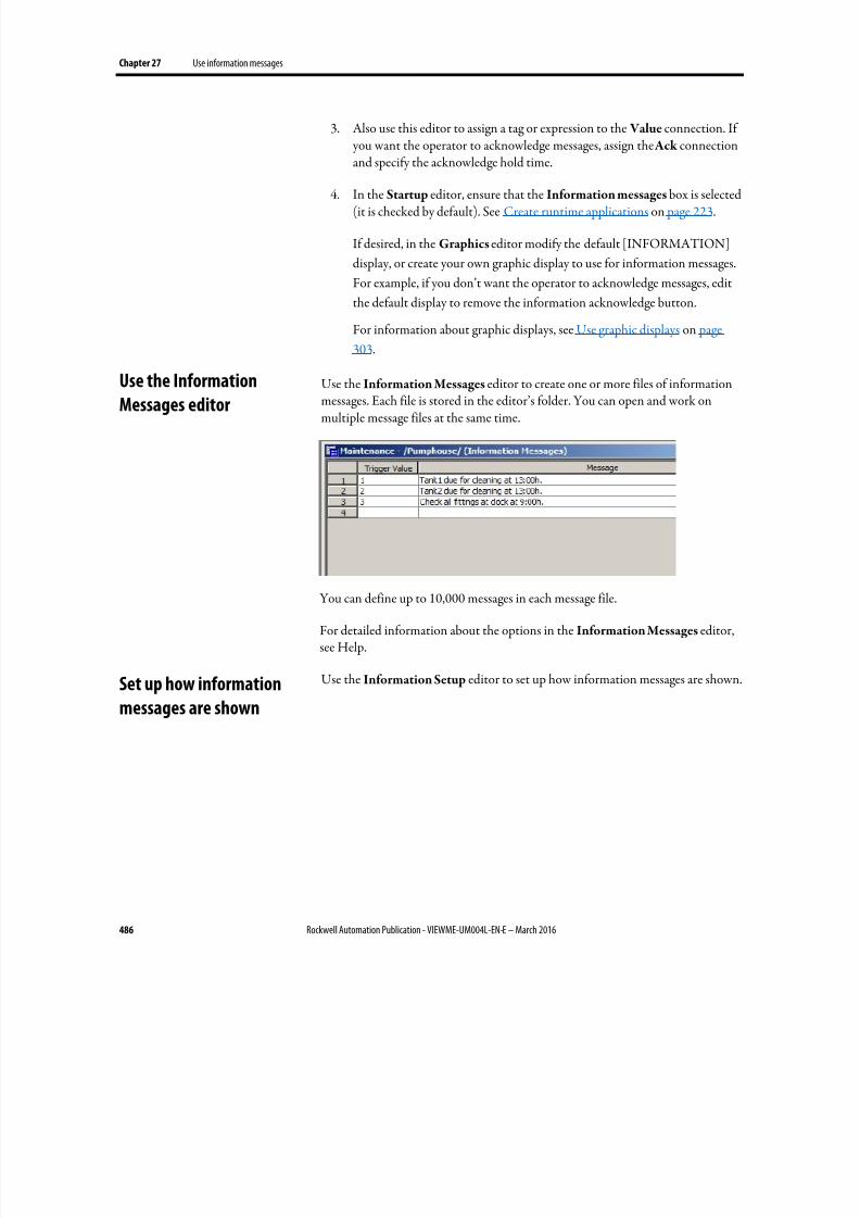
8/17/2019 FactoryTalk® View Machine Edition User's Guide
http://slidepdf.com/reader/full/factorytalk-view-machine-edition-users-guide 486/587
Chapter 27 Use information messages
486 Rockwell Automation Publication - VIEWME-UM004L-EN-E – March 2016
3. Also use this editor to assign a tag or expression to the Value connection. If you want the operator to acknowledge messages, assign the Ack connectionand specify the acknowledge hold time.
4.
In the Startup editor, ensure that the Information messages box is selected(it is checked by default). See Create runtime applications on page 223.
If desired, in the Graphics editor modify the default [INFORMATION]
display, or create your own graphic display to use for information messages.
For example, if you don’t want the operator to acknowledge messages, edit
the default display to remove the information acknowledge button.
For information about graphic displays, see Use graphic displays on page
303.
Use the Information Messages editor to create one or more files of informationmessages. Each file is stored in the editor’s folder. You can open and work onmultiple message files at the same time.
You can define up to 10,000 messages in each message file.
For detailed information about the options in the Information Messages editor,see Help.
Use the Information Setup editor to set up how information messages are shown.
Use the InformationMessages editor
Set up how information
messages are shown
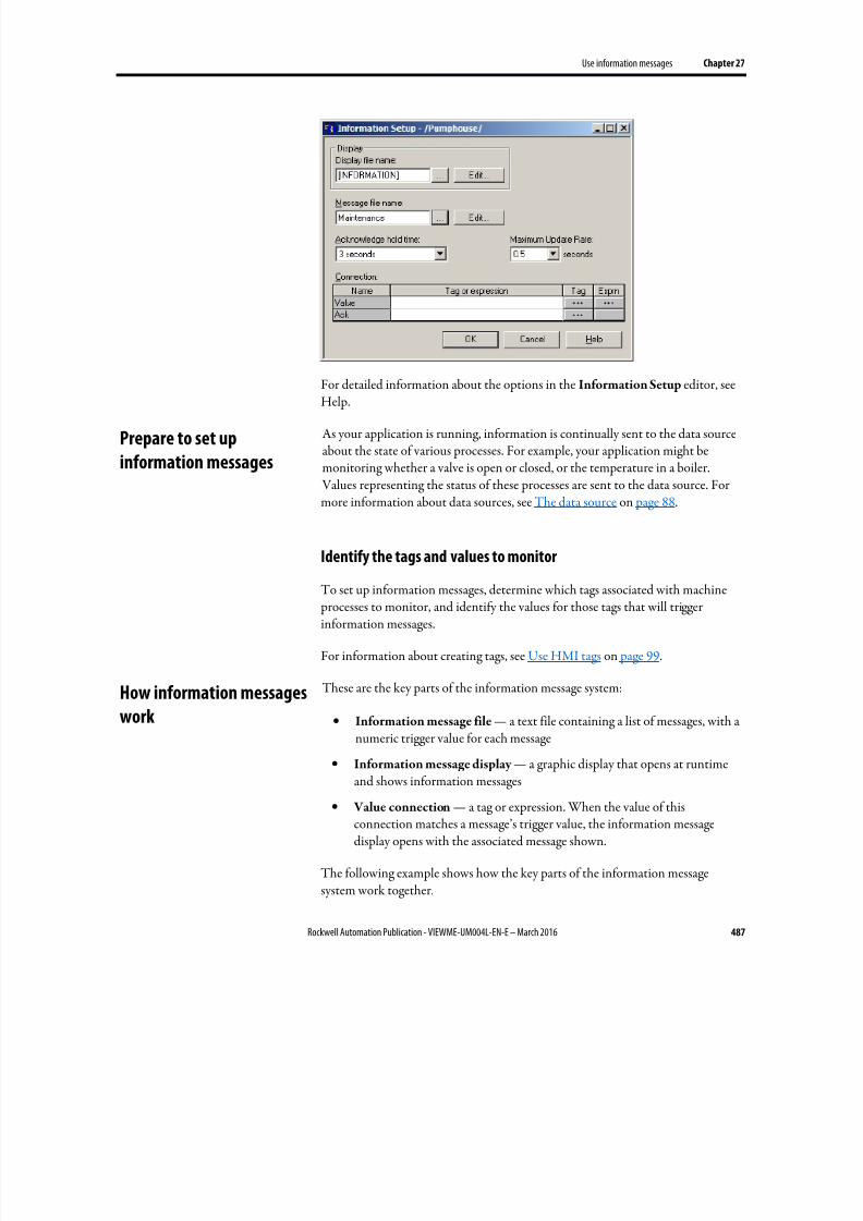
8/17/2019 FactoryTalk® View Machine Edition User's Guide
http://slidepdf.com/reader/full/factorytalk-view-machine-edition-users-guide 487/587
Use information messages Chapter 27
Rockwell Automation Publication - VIEWME-UM004L-EN-E – March 2016 487
For detailed information about the options in the Information Setup editor, seeHelp.
As your application is running, information is continually sent to the data sourceabout the state of various processes. For example, your application might bemonitoring whether a valve is open or closed, or the temperature in a boiler. Values representing the status of these processes are sent to the data source. Formore information about data sources, see The data source on page 88.
Identify the tags and values to monitor
To set up information messages, determine which tags associated with machine processes to monitor, and identify the values for those tags that will triggerinformation messages.
For information about creating tags, see Use HMI tags on page 99.
These are the key parts of the information message system:
• Information message file — a text file containing a list of messages, with anumeric trigger value for each message
•
Information message display — a graphic display that opens at runtimeand shows information messages
• Value connection — a tag or expression. When the value of thisconnection matches a message’s trigger value, the information messagedisplay opens with the associated message shown.
The following example shows how the key parts of the information messagesystem work together.
Prepare to set up
information messages
How information messages
work
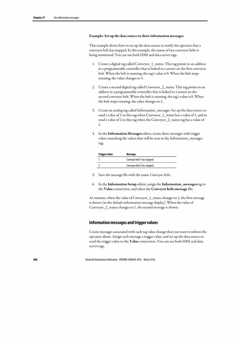
8/17/2019 FactoryTalk® View Machine Edition User's Guide
http://slidepdf.com/reader/full/factorytalk-view-machine-edition-users-guide 488/587
Chapter 27 Use information messages
488 Rockwell Automation Publication - VIEWME-UM004L-EN-E – March 2016
Example: Set up the data source to show information messages
This example shows how to set up the data source to notify the operator that aconveyor belt has stopped. In this example, the status of two conveyor belts isbeing monitored. You can use both HMI and data server tags.
1. Create a digital tag called Conveyor_1_status. This tag points to an addressin a programmable controller that is linked to a sensor on the first conveyorbelt. When the belt is running, the tag’s value is 0. When the belt stopsrunning, the value changes to 1.
2. Create a second digital tag called Conveyor_2_status. This tag points to anaddress in a programmable controller that is linked to a sensor on thesecond conveyor belt. When the belt is running, the tag’s value is 0. Whenthe belt stops running, the value changes to 1.
3. Create an analog tag called Information_messages. Set up the data source tosend a value of 1 to this tag when Conveyor_1_status has a value of 1, and tosend a value of 2 to this tag when the Conveyor_2_status tag has a value of1.
4. In the Information Messages editor, create these messages with trigger values matching the values that will be sent to the Information_messagestag:
Trigger value Message
1 Conveyor belt 1 has stopped.
2 Conveyor belt 2 has stopped.
5. Save the message file with the name Conveyor belts.
6. In the Information Setup editor, assign the Information_messages tag tothe Value connection, and select the Conveyor belts message file.
At runtime, when the value of Conveyor_1_status changes to 1, the first messageis shown (in the default information message display). When the value ofConveyor_2_status changes to 1, the second message is shown.
Information messages and trigger values
Create messages associated with each tag value change that you want to inform theoperator about. Assign each message a trigger value, and set up the data source tosend the trigger value to the Value connection. You can use both HMI and dataserver tags.
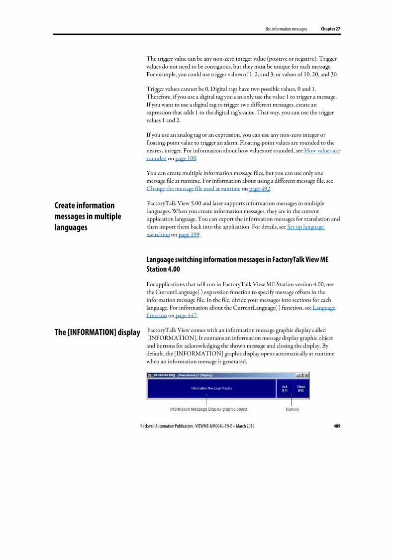
8/17/2019 FactoryTalk® View Machine Edition User's Guide
http://slidepdf.com/reader/full/factorytalk-view-machine-edition-users-guide 489/587
Use information messages Chapter 27
Rockwell Automation Publication - VIEWME-UM004L-EN-E – March 2016 489
The trigger value can be any non-zero integer value (positive or negative). Trigger values do not need to be contiguous, but they must be unique for each message.For example, you could use trigger values of 1, 2, and 3, or values of 10, 20, and 30.
Trigger values cannot be 0. Digital tags have two possible values, 0 and 1.Therefore, if you use a digital tag you can only use the value 1 to trigger a message.If you want to use a digital tag to trigger two different messages, create anexpression that adds 1 to the digital tag’s value. That way, you can use the trigger values 1 and 2.
If you use an analog tag or an expression, you can use any non-zero integer orfloating-point value to trigger an alarm. Floating-point values are rounded to thenearest integer. For information about how values are rounded, see How values arerounded on page 100.
You can create multiple information message files, but you can use only onemessage file at runtime. For information about using a different message file, seeChange the message file used at runtime on page 492.
FactoryTalk View 5.00 and later supports information messages in multiplelanguages. When you create information messages, they are in the currentapplication language. You can export the information messages for translation andthen import them back into the application. For details, see Set up languageswitching on page 199.
Language switching information messages in FactoryTalk View MEStation 4.00
For applications that will run in FactoryTalk View ME Station version 4.00, usethe CurrentLanguage( ) expression function to specify message offsets in theinformation message file. In the file, divide your messages into sections for eachlanguage. For information about the CurrentLanguage( ) function, see Languagefunction on page 447.
FactoryTalk View comes with an information message graphic display called[INFORMATION]. It contains an information message display graphic object
and buttons for acknowledging the shown message and closing the display. Bydefault, the [INFORMATION] graphic display opens automatically at runtime when an information message is generated.
Create information
messages in multiple
languages
The [INFORMATION] display
8/17/2019 FactoryTalk® View Machine Edition User's Guide
http://slidepdf.com/reader/full/factorytalk-view-machine-edition-users-guide 490/587
Chapter 27 Use information messages
490 Rockwell Automation Publication - VIEWME-UM004L-EN-E – March 2016
You can use the [INFORMATION] display as is, or modify the display. Forexample, you can change the color of the objects, or add and remove buttons. Or, you can create your own graphic display to use for showing information messages.In the Information Setup editor, specify the display to use.
Another option is to place the information message display object on a graphicdisplay that does not open automatically when a message is generated.
For information about creating your own information message display, see Create your own information message display on page 490.
The information message display graphic object
The [INFORMATION] display contains an information message display graphic
object, which lists one information message at a time.
For information about how the information message display object works atruntime, see How the information message display graphic object works on page491.
Buttons on the [INFORMATION] display
The [INFORMATION] display contains these buttons:
This button Does this
Ack (information acknowledge) Acknowledges the information message
Close (close display) Closes the information message graphic display.
You can assign any caption you choose to the labels on the buttons.
Use the information acknowledge button
When the operator presses the information acknowledge button, if the Ack
connection is assigned, the connection value is set to 1 at the data source. The value is held as long as the operator presses the button, or for the acknowledgehold time, whichever is longer. Then the connection is reset to 0.
You can create your own graphic display for showing information messages,containing an information message display graphic object and the buttons you want to use on the display.
If you create your own graphic display, use an On Top display and select theCannot Be Replaced option.
Create your own
information message
display
8/17/2019 FactoryTalk® View Machine Edition User's Guide
http://slidepdf.com/reader/full/factorytalk-view-machine-edition-users-guide 491/587
Use information messages Chapter 27
Rockwell Automation Publication - VIEWME-UM004L-EN-E – March 2016 491
For more information about the information message display graphic object, seeHow the information message display graphic object works on page 491.
For information about creating graphic displays and graphic objects, see Use
graphic displays on page 303 and Use graphic objects on page 335.
Open the display
The information message display you specify in the Information Setup editor(either the default [INFORMATION] display or your own display) isautomatically opened whenever the Value connection value matches a trigger value.
You can also create a Goto display button that the operator can press to open the
information message display. For information about setting up a Goto displaybutton and specifying the display to open, see Help.
Close the display
The information message display closes when the Value connection value changesto 0.
To automatically close the display when the operator acknowledges a message, setup the data source to set the Value connection to 0 when the Ack connection is
set to 1.
The operator can also close the display by pressing a close display button.
At runtime, when the Value connection at the data source changes from 0 to anon-zero value, the assigned information message display opens. If the valuematches a message’s trigger value, the associated information message appears inthe information message display graphic object. The object can be in the default[INFORMATION] display, in an information message display you have created,or can be placed in any display in your application.
What is shown
• If the Value connection is unassigned, the information message graphicdisplay never opens automatically. If the operator opens a graphic displaycontaining an information message display object, the object is blank.
• The Value connection is rounded up to the nearest integer. If the valuedoes not match any of the trigger values in the specified message file, thedisplay is filled with question marks (?).
Open and close the
information message
display
How the information
message display graphic
object works
8/17/2019 FactoryTalk® View Machine Edition User's Guide
http://slidepdf.com/reader/full/factorytalk-view-machine-edition-users-guide 492/587
Chapter 27 Use information messages
492 Rockwell Automation Publication - VIEWME-UM004L-EN-E – March 2016
For information about how values are rounded, see How values are rounded
on page 100.
• If the message is too long to fit in the information message display object,
the last shown character is replaced with an asterisk (*).
• When the Value connection value is 0, the information message graphicdisplay is closed.
• If you set up information messages in multiple languages, messages areshown in the current application language. When a language switch occurs,a message that was already in the information message display remains in thelanguage that it originally appeared in. New messages are shown in the newlanguage.
Your application can use only one message file at a time. Follow this procedure to
switch message files.
1. Shut down the application.
2. Start FactoryTalk View Studio and open the application.
3. In the Information Setup editor, specify the new information message file.
4. Create the runtime application. See Create runtime applications on page223.
5. Transfer the runtime application to the runtime platform.
For information about transferring applications to:
• A personal computer, see Run applications on a personal computer on page 229.
• A PanelView Plus or PanelView Plus CE terminal, see Transferapplications to a PanelView Plus terminal on page 247.
6. Run the new application.
Change the message file
used at runtime
8/17/2019 FactoryTalk® View Machine Edition User's Guide
http://slidepdf.com/reader/full/factorytalk-view-machine-edition-users-guide 493/587
Rockwell Automation Publication - VIEWME-UM004L-EN-E – March 2016 493
Chapter 28
Set up trends
This chapter describes:
• What trends are.
• Summary of steps for creating a trend graphic object.
• Create trends, and the Trend Object Properties dialog box.
•
The parts of the trend graphic object.• The different chart types.
• Choose colors, fonts, lines, and markers for the trend.
• Test the trend.
• Use objects from the Trends graphic library.
• Use buttons to control the trend at runtime.
• Print trend data.
• Runtime errors for trends.
A trend is a visual representation of current or historical tag values. The trend provides operators with a way of tracking plant activity as it is happening.
You can:
• Plot data for as many as eight tags or expressions on one trend.
• Create a trend that is part of a graphic display or acts as the entire graphicdisplay.
• Plot data over time, or plot one variable against another in an XY Plot chart
to show the relationship between them.• Show isolated or non-isolated graphs. Isolated graphing places each pen in a
separate band of the chart. With non-isolated graphing, pen values canoverlap.
• Create buttons to allow the operator to pause, scroll, and print the trenddata.
About trends
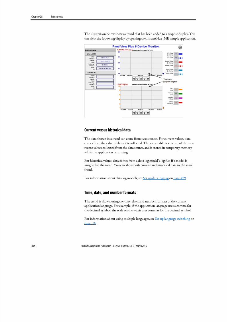
8/17/2019 FactoryTalk® View Machine Edition User's Guide
http://slidepdf.com/reader/full/factorytalk-view-machine-edition-users-guide 494/587
Chapter 28 Set up trends
494 Rockwell Automation Publication - VIEWME-UM004L-EN-E – March 2016
The illustration below shows a trend that has been added to a graphic display. Youcan view the following display by opening the InstantFizz_ME sample application.
Current versus historical data
The data shown in a trend can come from two sources. For current values, datacomes from the value table as it is collected. The value table is a record of the mostrecent values collected from the data source, and is stored in temporary memory while the application is running.
For historical values, data comes from a data log model’s log file, if a model isassigned to the trend. You can show both current and historical data in the sametrend.
For information about data log models, see Set up data logging on page 479.
Time, date, and number formats
The trend is shown using the time, date, and number formats of the currentapplication language. For example, if the application language uses a comma forthe decimal symbol, the scale on the y-axis uses commas for the decimal symbol.
For information about using multiple languages, see Set up language switching on page 199.
8/17/2019 FactoryTalk® View Machine Edition User's Guide
http://slidepdf.com/reader/full/factorytalk-view-machine-edition-users-guide 495/587
Set up trends Chapter 28
Rockwell Automation Publication - VIEWME-UM004L-EN-E – March 2016 495
Follow these steps to create a trend:
1. To plot historical data, create a data log model in the Data Log Models editor. For information, see Set up data logging on page 479.
2. Create a trend graphic object in the Graphics editor, as described on Createtrend objects on page 495.
3. Set up the trend in the Trend Object Properties dialog box. For detailsabout the options in the dialog box, see Help.
4. If desired, create a next pen button, a pause button, or key buttons on thesame graphic display, to allow the operator to switch between pens, pausethe trend, or scroll the trend.
For information about the buttons you can use with trends, see Use buttonsto control the trend at runtime on page 503.
5. To keep a printed record of the trend data, provide a way for the operator to print the graphic display. For information see Print trend data on page 504.
To create a trend object
1. In the Graphics editor, create or open a graphic display.
2.
Select the Trend drawing tool by doing one of the following:
• In the Objects toolbox, click the Trend tool.
• From the Objects menu, select Trending > Trend.
3. Drag the mouse to create a box approximately the size you want for thetrend.
4. Double-click the trend to open the Trend Object Properties dialog box.
5.
Set up the trend. For details, see Help.
Once you have set up the trend, you can edit it as you would any other graphicobject. You can move it, resize it, attach animation to it, and so on. You can alsouse this object in other graphic displays by dragging it from one display anddropping it into another.
For more information about graphic objects, see Use graphic objects on page 335.
Steps for creating a trend
Create trend objects
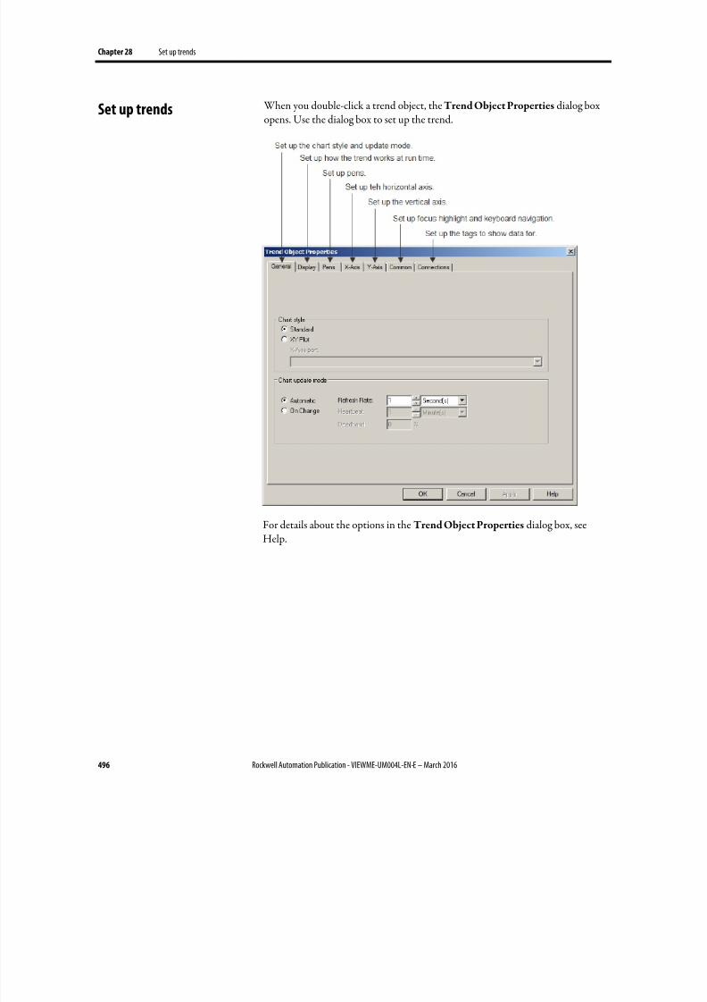
8/17/2019 FactoryTalk® View Machine Edition User's Guide
http://slidepdf.com/reader/full/factorytalk-view-machine-edition-users-guide 496/587
Chapter 28 Set up trends
496 Rockwell Automation Publication - VIEWME-UM004L-EN-E – March 2016
When you double-click a trend object, the Trend Object Properties dialog boxopens. Use the dialog box to set up the trend.
For details about the options in the Trend Object Properties dialog box, seeHelp.
Set up trends
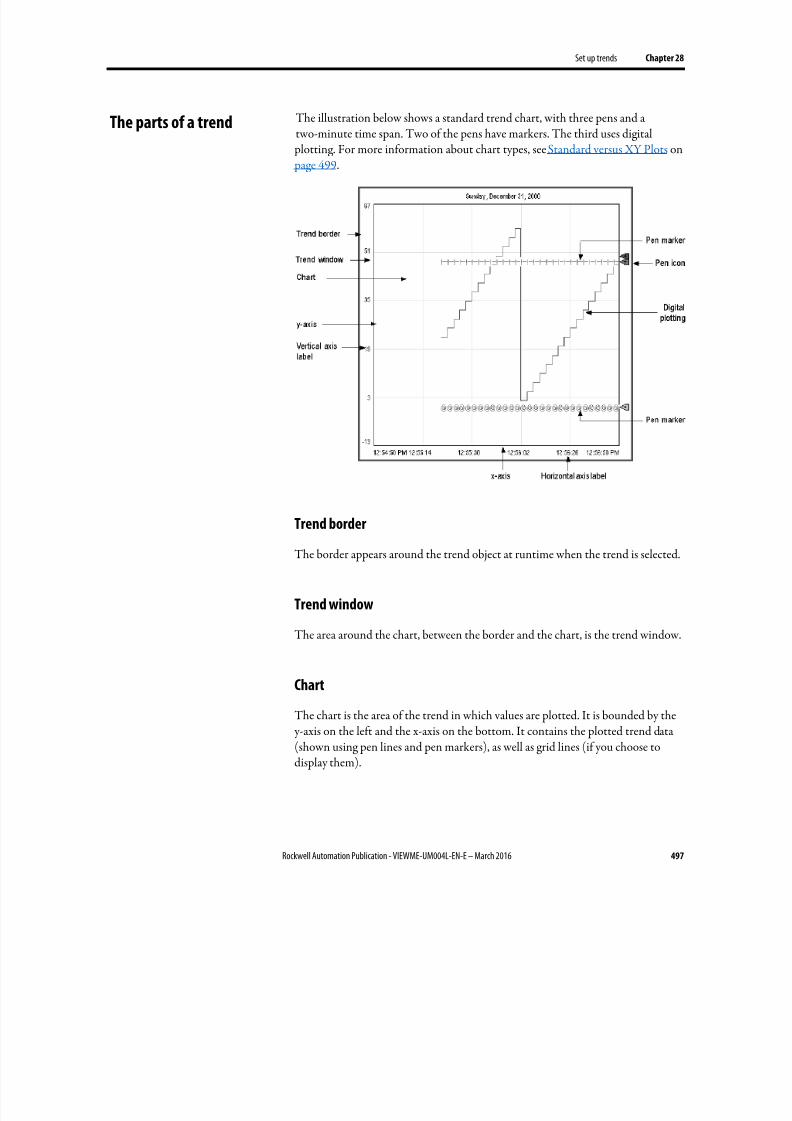
8/17/2019 FactoryTalk® View Machine Edition User's Guide
http://slidepdf.com/reader/full/factorytalk-view-machine-edition-users-guide 497/587
Set up trends Chapter 28
Rockwell Automation Publication - VIEWME-UM004L-EN-E – March 2016 497
The illustration below shows a standard trend chart, with three pens and atwo-minute time span. Two of the pens have markers. The third uses digital
plotting. For more information about chart types, see Standard versus XY Plots on page 499.
Trend border
The border appears around the trend object at runtime when the trend is selected.
Trend window
The area around the chart, between the border and the chart, is the trend window.
Chart
The chart is the area of the trend in which values are plotted. It is bounded by the y-axis on the left and the x-axis on the bottom. It contains the plotted trend data(shown using pen lines and pen markers), as well as grid lines (if you choose todisplay them).
The parts of a trend
8/17/2019 FactoryTalk® View Machine Edition User's Guide
http://slidepdf.com/reader/full/factorytalk-view-machine-edition-users-guide 498/587
Chapter 28 Set up trends
498 Rockwell Automation Publication - VIEWME-UM004L-EN-E – March 2016
Y-axis
The y-axis is the left vertical edge of the chart. It is also known as the vertical axis.
Vertical axis labels
The vertical axis labels show the scale (range) of values for the pens. If desired, youcan set up the trend to omit the vertical axis labels.
The minimum and maximum values for the scale can be determined automatically(using the best fit for the current data), be derived from a pen’s minimum andmaximum values, use a constant value, or be controlled by tags.
You can set up the trend so all pens use the same scale, or use individual ranges for
each pen. If you choose the latter method, create a next pen button in the graphicdisplay, to allow operators to view the range for each pen. When the operator presses the button, the vertical axis changes to the new pen’s range.
For example, if Pen 1 has a minimum value of 10 and a maximum value of 100, therange on the vertical axis is 10 to 100 when the pen is selected. If Pen 2 has aminimum of -10 and a maximum of 50, the range on the vertical axis changes to-10 to 50 when the operator presses the next pen button.
X-axis
The x-axis is the bottom horizontal edge of the chart. It is also known as thehorizontal axis.
Horizontal axis labels
For standard charts, the horizontal axis labels indicate the time span covered bythe trend. For XY Plot charts, the horizontal axis labels show the scale (range) of values for the pen selected to serve as the x-axis pen.
If desired, you can set up the trend to omit the horizontal axis labels. The numberof labels depends on the size of the trend object and the number of vertical gridlines.
Pens
Pens are the lines and symbols used to represent values. The values can be tags youare monitoring, expressions that manipulate tag values, or constants.
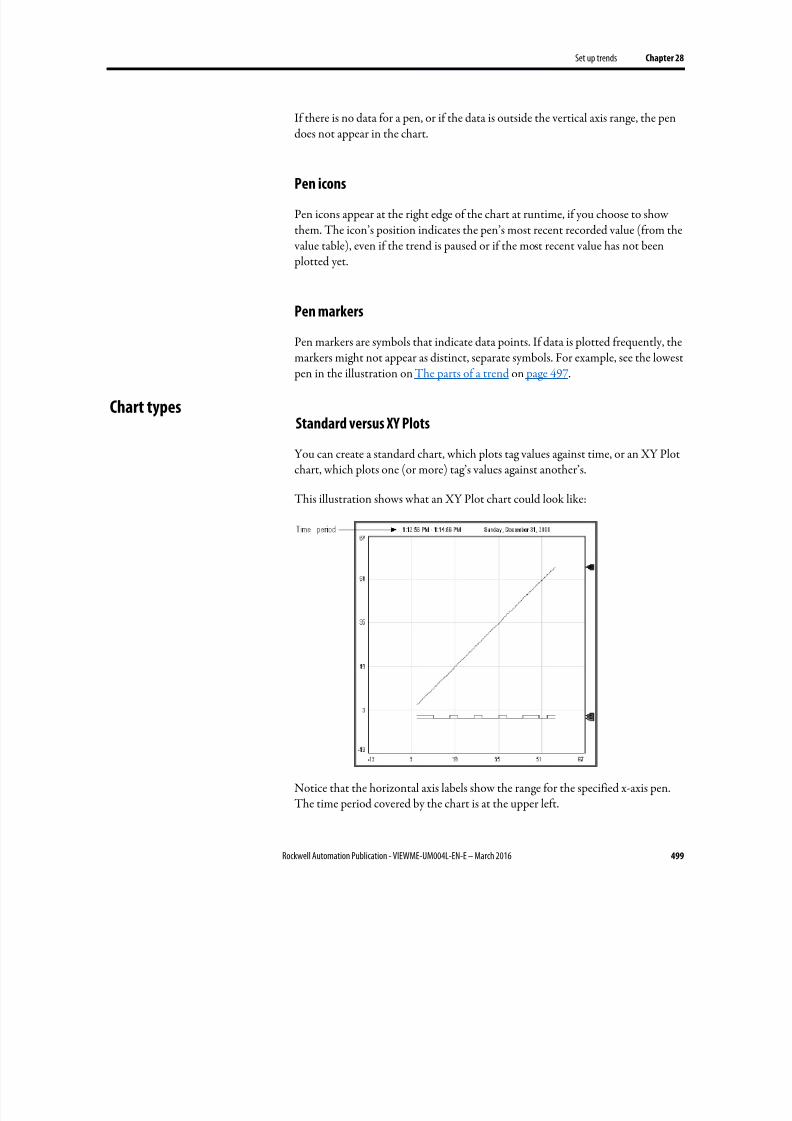
8/17/2019 FactoryTalk® View Machine Edition User's Guide
http://slidepdf.com/reader/full/factorytalk-view-machine-edition-users-guide 499/587
Set up trends Chapter 28
Rockwell Automation Publication - VIEWME-UM004L-EN-E – March 2016 499
If there is no data for a pen, or if the data is outside the vertical axis range, the pendoes not appear in the chart.
Pen icons
Pen icons appear at the right edge of the chart at runtime, if you choose to showthem. The icon’s position indicates the pen’s most recent recorded value (from the value table), even if the trend is paused or if the most recent value has not been plotted yet.
Pen markers
Pen markers are symbols that indicate data points. If data is plotted frequently, themarkers might not appear as distinct, separate symbols. For example, see the lowest pen in the illustration on The parts of a trend on page 497.
Standard versus XY Plots
You can create a standard chart, which plots tag values against time, or an XY Plotchart, which plots one (or more) tag’s values against another’s.
This illustration shows what an XY Plot chart could look like:
Notice that the horizontal axis labels show the range for the specified x-axis pen.The time period covered by the chart is at the upper left.
Chart types
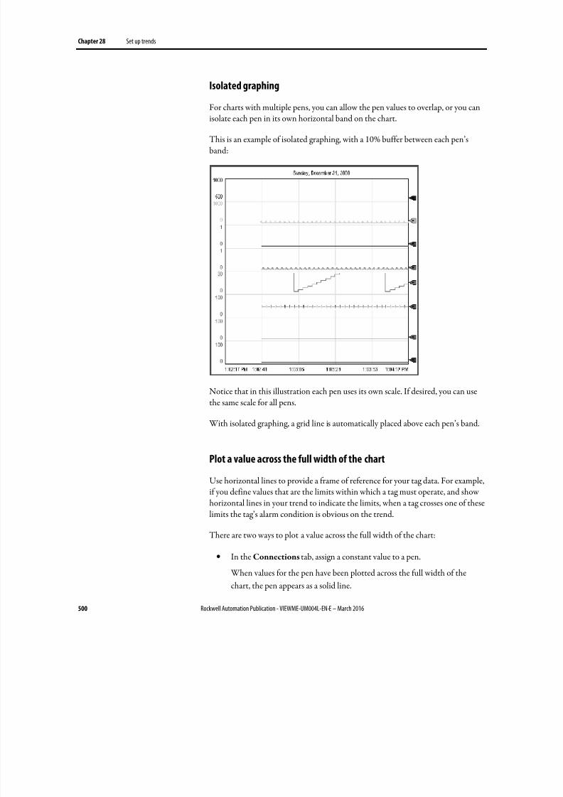
8/17/2019 FactoryTalk® View Machine Edition User's Guide
http://slidepdf.com/reader/full/factorytalk-view-machine-edition-users-guide 500/587
Chapter 28 Set up trends
500 Rockwell Automation Publication - VIEWME-UM004L-EN-E – March 2016
Isolated graphing
For charts with multiple pens, you can allow the pen values to overlap, or you can
isolate each pen in its own horizontal band on the chart.
This is an example of isolated graphing, with a 10% buffer between each pen’sband:
Notice that in this illustration each pen uses its own scale. If desired, you can usethe same scale for all pens.
With isolated graphing, a grid line is automatically placed above each pen’s band.
Plot a value across the full width of the chart
Use horizontal lines to provide a frame of reference for your tag data. For example,
if you define values that are the limits within which a tag must operate, and showhorizontal lines in your trend to indicate the limits, when a tag crosses one of theselimits the tag’s alarm condition is obvious on the trend.
There are two ways to plot a value across the full width of the chart:
• In the Connections tab, assign a constant value to a pen.
When values for the pen have been plotted across the full width of the
chart, the pen appears as a solid line.
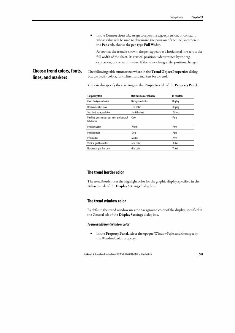
8/17/2019 FactoryTalk® View Machine Edition User's Guide
http://slidepdf.com/reader/full/factorytalk-view-machine-edition-users-guide 501/587
Set up trends Chapter 28
Rockwell Automation Publication - VIEWME-UM004L-EN-E – March 2016 501
• In the Connections tab, assign to a pen the tag, expression, or constant whose value will be used to determine the position of the line, and then inthe Pens tab, choose the pen type Full Width.
As soon as the trend is shown, the pen appears as a horizontal line across thefull width of the chart. Its vertical position is determined by the tag,
expression, or constant’s value. If the value changes, the position changes.
The following table summarizes where in the Trend Object Properties dialogbox to specify colors, fonts, lines, and markers for a trend.
You can also specify these settings in the Properties tab of the Property Panel.
To specify this Use this box or column In this tab
Chart background color Background color Display
Horizontal label color Text color Display
Text font, style, and size Font (button) Display
Pen line, pen marker, pen icon, and verticallabel color
Color Pens
Pen line width Width Pens
Pen line style Style Pens
Pen marker Marker Pens
Vertical grid line color Grid color X-Axis
Horizontal grid line color Grid color Y-Axis
The trend border color
The trend border uses the highlight color for the graphic display, specified in theBehavior tab of the Display Settings dialog box.
The trend window color
By default, the trend window uses the background color of the display, specified inthe General tab of the Display Settings dialog box.
To use a different window color
• In the Property Panel, select the opaque WindowStyle, and then specifythe WindowColor property.
Choose trend colors, fonts,
lines, and markers
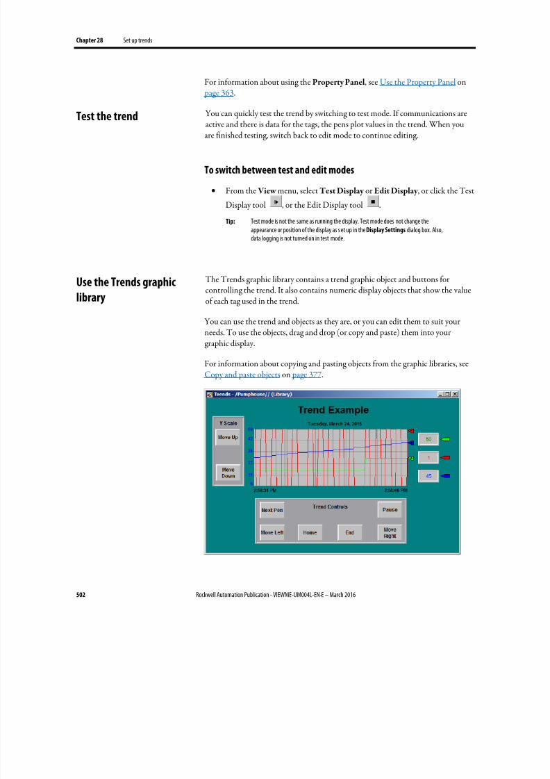
8/17/2019 FactoryTalk® View Machine Edition User's Guide
http://slidepdf.com/reader/full/factorytalk-view-machine-edition-users-guide 502/587
Chapter 28 Set up trends
502 Rockwell Automation Publication - VIEWME-UM004L-EN-E – March 2016
For information about using the Property Panel, see Use the Property Panel on page 363.
You can quickly test the trend by switching to test mode. If communications are
active and there is data for the tags, the pens plot values in the trend. When youare finished testing, switch back to edit mode to continue editing.
To switch between test and edit modes
• From the View menu, select Test Display or Edit Display , or click the Test
Display tool , or the Edit Display tool .
Tip: Test mode is not the same as running the display. Test mode does not change theappearance or position of the display as s et up in the Display Settings dialog box. Also,
data logging is not turned on in test mode.
The Trends graphic library contains a trend graphic object and buttons forcontrolling the trend. It also contains numeric display objects that show the valueof each tag used in the trend.
You can use the trend and objects as they are, or you can edit them to suit yourneeds. To use the objects, drag and drop (or copy and paste) them into yourgraphic display.
For information about copying and pasting objects from the graphic libraries, seeCopy and paste objects on page 377.
Test the trend
Use the Trends graphic
library
8/17/2019 FactoryTalk® View Machine Edition User's Guide
http://slidepdf.com/reader/full/factorytalk-view-machine-edition-users-guide 503/587
Set up trends Chapter 28
Rockwell Automation Publication - VIEWME-UM004L-EN-E – March 2016 503
To use the Trends graphic library
1. Open the Graphics folder, and then open the Libraries folder.
2.
Double-click the Trends library.
3. Drag and drop or copy and paste objects into your display.
You can use button graphic objects with the trend, to allow the operator to pausethe trend, switch between pens, or scroll the trend. You can link buttons to aspecific trend object, or set up a button to work with whichever object is selectedin the graphic display. For information about linking buttons to objects, see Linkbuttons to objects on page 408.
Use these buttons with trends:
This button Does this
Pause Toggles between pausing and automatic scrolling.
When the trend is paused, the pen icons continue to move vertically to indicate the pens’current values.
When the trend resumes scrolling, values that occurred while the trend was paused are filledin, bringing the trend up to the current time (unless you are scrolling historical data).
Next pen Changes the vertical axis labels to the scale for the next pen. The color of the labels matchesthe color of the selected pen.
Move up Scrolls up to show higher values on the vertical scale. For example, if the visible scale range is
0 to 100, pressing move up could change the visible range to 10 to 110.The incremental amount the axis scrolls depends on the pen’s range and the number ofhorizontal grid lines.
This button does not work if the Minimum / maximum value option in the Y-Axis tab is setto Automatic.
Move down Scrolls down to show lower values on the vertical scale.
This button does not work if the Minimum /maximum value option in the Y-Axis tab isset to Automatic.
Move left Pauses the trend and scrolls to the left.
Move right Pauses the trend and scrolls to the right.
Home Pauses the trend and moves to the earliest data in the trend.End Resumes trend scrolling and moves to the current (latest) data in the trend.
To see how the buttons work with the trend, open the Trends graphic library (seeUse the Trends graphic library on page 502), and start test mode.
For information about creating buttons, see Use graphic objects on page 335. Fordetails about setting up the buttons, see Help.
Use buttons to control the
trend at runtime
8/17/2019 FactoryTalk® View Machine Edition User's Guide
http://slidepdf.com/reader/full/factorytalk-view-machine-edition-users-guide 504/587
Chapter 28 Set up trends
504 Rockwell Automation Publication - VIEWME-UM004L-EN-E – March 2016
To print trend data at runtime, provide the operator with a method for printingthe graphic display.
You can use these methods to print graphic displays at runtime:
• Create a display print button. For information about creating graphicobjects, see Use graphic objects on page 335.
• Assign a tag or expression to the Remote Display Print connection (in theGlobal Connections editor). When the value of the tag or expressionchanges from 0 to a non-zero value, the current display is automatically printed.
Program the data source to trigger the change as often as you want the data
printed.
For more information about setting up remote display printing, see Set upglobal connections on page 111.
Everything on the screen is printed, including the current display, pop-up windows, and any visible background applications.
For information about specifying which printer to use at runtime for applicationsthat will run on a personal computer or a MobileView terminal, see Specify the printers to use at runtime on page 238.
For information about specifying printer options for applications that will run on
a PanelView Plus 7, PanelView Plus 6, PanelView Plus, PanelView Plus Compact,or PanelView Plus CE terminal, see the PanelView Plus Terminals User Manual .
Improve clarity of the trend printout
Depending on what type of printer you use, pen lines with a width of 1 pixel mightnot appear in the printout. Choose high-contrast colors and wider line widths toensure that the trend data prints clearly.
If data for the trend is not available at runtime due to communication errors, a
message is sent to FactoryTalk Diagnostics.
See Help for information about solving common trend problems.
Print trend data
Runtime errors for the
trend
8/17/2019 FactoryTalk® View Machine Edition User's Guide
http://slidepdf.com/reader/full/factorytalk-view-machine-edition-users-guide 505/587
Rockwell Automation Publication - VIEWME-UM004L-EN-E – March 2016 505
Chapter 29
Set up RecipePlus
This chapter describes:
• What recipes are
• Summary of steps for creating a recipe system
• How the recipe system works
•
Specify the runtime location of recipe files• Create recipe files
• Compare recipes
• Create RecipePlus buttons, selectors, and tables
• Test RecipePlus objects
• Use objects from the RecipePlus_Componentsgraphic library
• Use buttons with the recipe objects
• View data values that are saved at runtime
A recipe is a set of numeric and string data values (ingredients) that can bedownloaded to their associated tags at the data source. Each ingredient has a
pre-set data value assigned to it. The set of data values for all the ingredients in arecipe is called a data set. The set of numeric and string tags assigned to theingredients in the recipe is called a tag set. The ingredients, data sets, and tag setsare stored together in a recipe file.
You can create different pairs of data sets and tag sets for the same set ofingredients. Each pairing of data set with tag set is called a unit. Each unit is like aunique recipe. At runtime, the operator can select the unit (recipe) that applies to
the current operation.
For example, a bakery making whole wheat bread could use the same ingredientsand tag sets, but depending on the type of crust desired, could use different datasets to specify different baking temperatures. As another example, you might wantto have multiple production lines baking the same bread. In this case, the data setfor all the production lines would be the same, but the tags receiving the recipeinformation would be different for each production line. Units allow you tocombine different tag sets and data sets for the same set of ingredients.
About recipes
8/17/2019 FactoryTalk® View Machine Edition User's Guide
http://slidepdf.com/reader/full/factorytalk-view-machine-edition-users-guide 506/587
Chapter 29 Set up RecipePlus
506 Rockwell Automation Publication - VIEWME-UM004L-EN-E – March 2016
The FactoryTalk View RecipePlus system allows you to create up to 15,000ingredients, 500 data sets, 50 tag sets, and 2,500 units for each recipe file. You cancreate data sets at development time, edit them at runtime, and also create newdata sets from tag values at runtime. You can write the data set values to tags, or write tag values to data sets.
The RecipePlus system can be used for manufacturing food and beverages, but itcan also be used for any application where you want to show, edit, download, orsave multiple values at once. For example, recipes are used in the petrochemicaland pharmaceutical industries. In the pharmaceutical industry, you could userecipes to design flexible packaging, creating recipes that specify the number oftissues to put in a box or the number of milliliters of shampoo to put in a bottle.
Follow these steps to create a recipe system:
1.
In the RecipePlus Setup editor, specify the runtime location for recipefiles. The files can be stored with the application or in a separate location.For details, see Specify the runtime file location on page 508.
2. In the RecipePlus Editor , set up ingredients, data sets, tag sets, and units.You can also specify a percent complete tag and a status tag for the recipe.For details, see Set up recipe files on page 510.
3. Create a display in the Graphics editor, containing a RecipePlus selector,table, and buttons. For details, see Create RecipePlus objects on page 512.
4. If desired, create key buttons on the same graphic display, to allow theoperator to use the selector and table without a keyboard.
For information about the buttons you can use with recipes, see Use
buttons with recipe objects on page 514.
A recipe system consists of a recipe file and the graphic objects used to work withthe ingredients at runtime.
RecipePlus selector
Use the RecipePlus selector to select the recipe file and unit to work with.
RecipePlus table
Use the RecipePlus table to show the selected recipe file’s ingredients, tag values,and data set values. The operator can edit data set values in the table, unless youselect the View only option.
Steps for creating a recipe
system
How the recipe system
works
8/17/2019 FactoryTalk® View Machine Edition User's Guide
http://slidepdf.com/reader/full/factorytalk-view-machine-edition-users-guide 507/587
Set up RecipePlus Chapter 29
Rockwell Automation Publication - VIEWME-UM004L-EN-E – March 2016 507
If desired, you can include a Compare column in the table, to compare tag valuesto data sets at a glance. If you choose this option, FactoryTalk View shows an X inthe Compare column when the tag value and data set value for an ingredientdiffer. Ingredients with an X are listed first.
RecipePlus button
Use the RecipePlus button to perform actions on the selected recipe’s ingredients.The recipe is selected using the RecipePlus selector object. Set up a separateRecipePlus button for each action you want to perform:
• Download — write the data set values to tags, for all the ingredients in theselected recipe.
•
Upload — write tag values to the data set, for all the ingredients in theselected recipe. If all values are uploaded successfully, the recipe file is saved.
• Upload and Create — write tag values for all the ingredients in the selectedrecipe to a new data set, creating a new unit. The operator is prompted for aname for the new unit. If all values are uploaded successfully, the recipe fileis saved.
The new data set is named Data Set n, where n is the next available number
(starting at 1) that will create a unique data set name.
• Restore — show the selected recipe in the RecipePlus table.
•
Save — save the data set values for the recipe file and unit shown in theRecipePlus table. If the operator made changes in the data set values usingthe string pop-up keyboard or numeric pop-up keypad, the new values inthe table overwrite existing data set values (if any) for the unit in the recipefile.
• Delete — delete the recipe unit selected in the RecipePlus selector object.
• Rename — rename the recipe unit selected in the RecipePlus selectorobject.
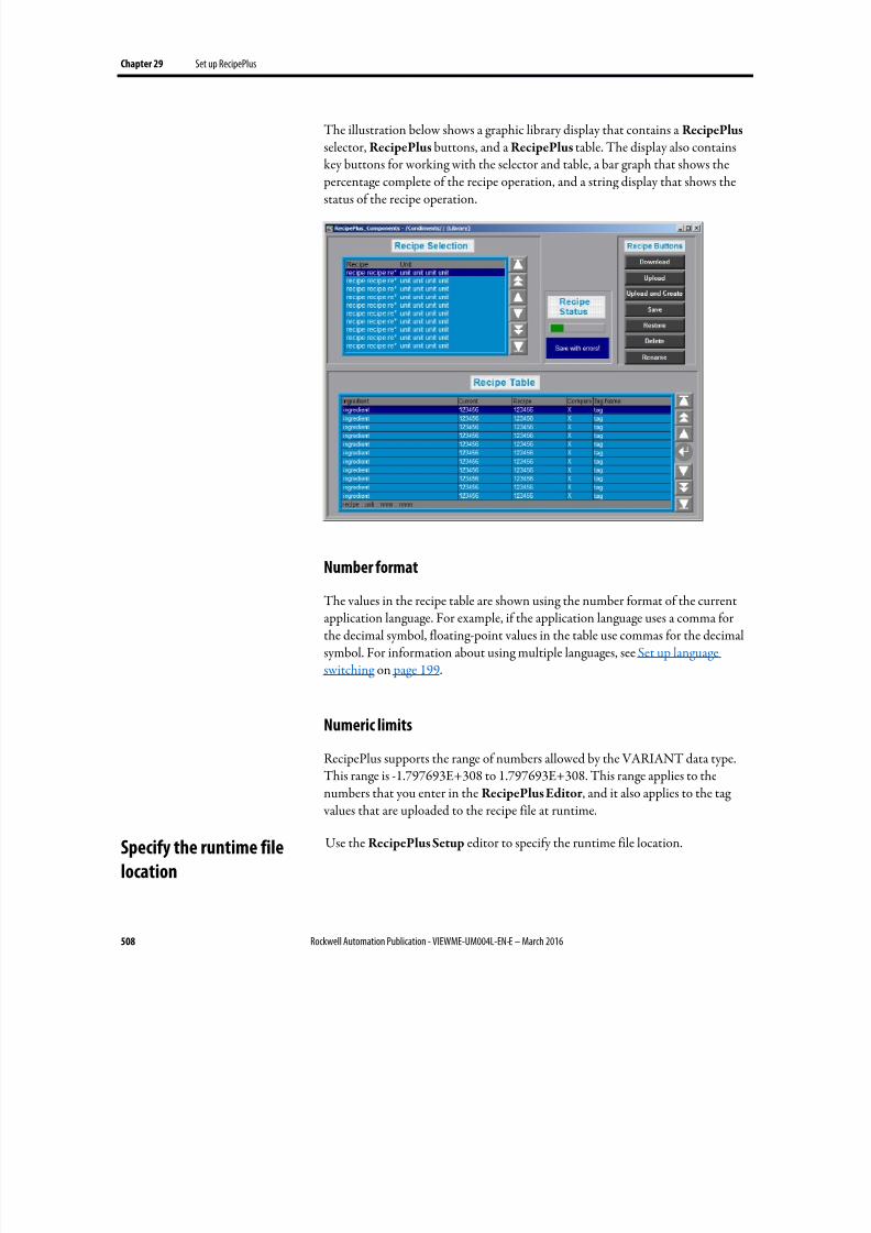
8/17/2019 FactoryTalk® View Machine Edition User's Guide
http://slidepdf.com/reader/full/factorytalk-view-machine-edition-users-guide 508/587
Chapter 29 Set up RecipePlus
508 Rockwell Automation Publication - VIEWME-UM004L-EN-E – March 2016
The illustration below shows a graphic library display that contains a RecipePlus selector, RecipePlus buttons, and a RecipePlus table. The display also containskey buttons for working with the selector and table, a bar graph that shows the percentage complete of the recipe operation, and a string display that shows thestatus of the recipe operation.
Number formatThe values in the recipe table are shown using the number format of the currentapplication language. For example, if the application language uses a comma forthe decimal symbol, floating-point values in the table use commas for the decimalsymbol. For information about using multiple languages, see Set up languageswitching on page 199.
Numeric limits
RecipePlus supports the range of numbers allowed by the VARIANT data type.This range is -1.797693E+308 to 1.797693E+308. This range applies to thenumbers that you enter in the RecipePlus Editor , and it also applies to the tag values that are uploaded to the recipe file at runtime.
Use the RecipePlus Setup editor to specify the runtime file location.Specify the runtime file
location
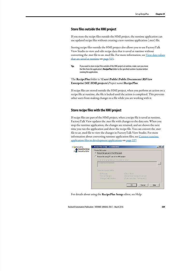
8/17/2019 FactoryTalk® View Machine Edition User's Guide
http://slidepdf.com/reader/full/factorytalk-view-machine-edition-users-guide 509/587
Set up RecipePlus Chapter 29
Rockwell Automation Publication - VIEWME-UM004L-EN-E – March 2016 509
Store files outside the HMI project
If you store the recipe files outside the HMI project, the runtime application can
use updated recipe files without creating a new runtime application (.mer) file.
Storing recipe files outside the HMI project also allows you to use FactoryTalk View Studio to view and edit recipe data that is saved at runtime withoutconverting the .mer file to an .med file. For more information, see View data valuesthat are saved at runtime on page 515.
Tip: If you want to store recipe fi les outside of the HMI project at runtime, make sure you movethe files from the application’s RecipePlus folder to the specified runtime location beforerunning the application.
The RecipePlus folder is \Users\Public\Public Documents\RSView
Enterprise\ME\HMI projects\ Project name\RecipePlus
If recipe files are stored outside the HMI project, when you perform an action on arecipe file at runtime, the file is locked until the action is completed. This preventsother users from making changes to a file while you are working with it.
Store recipe files with the HMI project
If recipe files are part of the HMI project, when a recipe file is saved at runtime,FactoryTalk View updates the .mer file with changes to the data sets. When you
stop the runtime application, the changes are retained, and are shown the nexttime you run the application and show the recipe file. You can convert the .merfile to an .med file to view the changes in FactoryTalk View Studio. For moreinformation about converting runtime application files, see Convert runtimeapplication files to development applications on page 227.
For details about using the RecipePlus Setup editor, see Help.
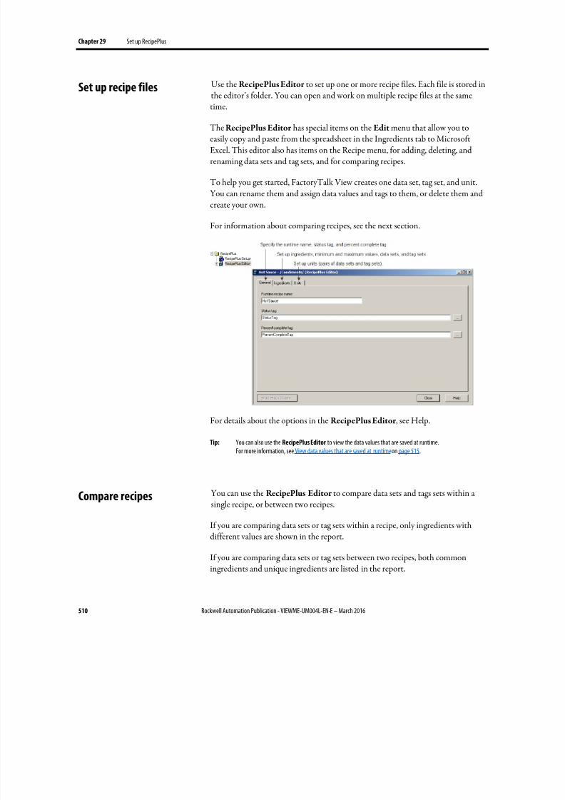
8/17/2019 FactoryTalk® View Machine Edition User's Guide
http://slidepdf.com/reader/full/factorytalk-view-machine-edition-users-guide 510/587
Chapter 29 Set up RecipePlus
510 Rockwell Automation Publication - VIEWME-UM004L-EN-E – March 2016
Use the RecipePlus Editor to set up one or more recipe files. Each file is stored inthe editor’s folder. You can open and work on multiple recipe files at the sametime.
The RecipePlus Editor has special items on the Edit menu that allow you toeasily copy and paste from the spreadsheet in the Ingredients tab to MicrosoftExcel. This editor also has items on the Recipe menu, for adding, deleting, andrenaming data sets and tag sets, and for comparing recipes.
To help you get started, FactoryTalk View creates one data set, tag set, and unit.You can rename them and assign data values and tags to them, or delete them andcreate your own.
For information about comparing recipes, see the next section.
For details about the options in the RecipePlus Editor , see Help.
Tip: You can also use the RecipePlus Editor to view the data values that are saved at runtime.For more information, see View data values that are saved at runtime on page 515.
You can use the RecipePlus Editor to compare data sets and tags sets within asingle recipe, or between two recipes.
If you are comparing data sets or tag sets within a recipe, only ingredients withdifferent values are shown in the report.
If you are comparing data sets or tag sets between two recipes, both commoningredients and unique ingredients are listed in the report.
Set up recipe files
Compare recipes
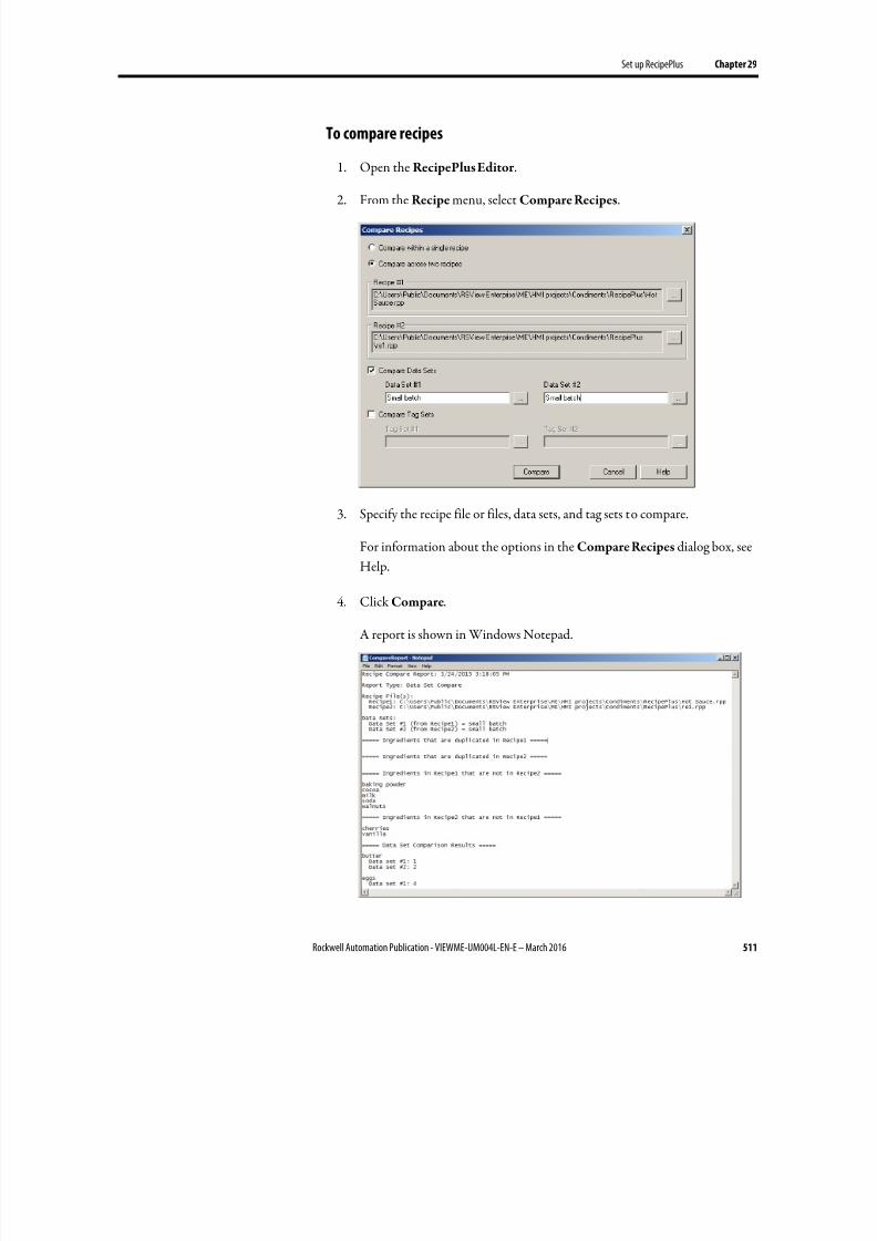
8/17/2019 FactoryTalk® View Machine Edition User's Guide
http://slidepdf.com/reader/full/factorytalk-view-machine-edition-users-guide 511/587
Set up RecipePlus Chapter 29
Rockwell Automation Publication - VIEWME-UM004L-EN-E – March 2016 511
To compare recipes
1. Open the RecipePlus Editor .
2.
From the Recipe menu, select Compare Recipes.
3. Specify the recipe file or files, data sets, and tag sets to compare.
For information about the options in the Compare Recipes dialog box, see
Help.
4. Click Compare.
A report is shown in Windows Notepad.
8/17/2019 FactoryTalk® View Machine Edition User's Guide
http://slidepdf.com/reader/full/factorytalk-view-machine-edition-users-guide 512/587
Chapter 29 Set up RecipePlus
512 Rockwell Automation Publication - VIEWME-UM004L-EN-E – March 2016
Time and date formats
The time and date in the report use the time and short date format for the current
application language. For information about using multiple languages, see Set uplanguage switching on page 199.
You can use the RecipePlus Editor to print recipe data sets. For informationabout printing from editors, see Print on page 51.
You can create one RecipePlus table and RecipePlus selector per graphic display.You can create multiple RecipePlus buttons in a display, with a different actionassigned to each.
The objects and button actions to use depend on how you want to use your recipesystem. For example, if you just want to write data set values to tags, all you need is
a RecipePlus selector and a RecipePlus button with the download action. Forinformation about how the different objects in the recipe system work, see Howthe recipe system works on page 506.
To create a recipe object
1. In the Graphics editor, create or open a graphic display.
2. Select a RecipePlus drawing tool by doing one of the following:
•
In the Objects toolbox, click the RecipePlus Button, RecipePlusSelector , or RecipePlus Table tool.
• From the Objects menu, select RecipePlus, and then click RecipePlus
Button, RecipePlus Selector , or RecipePlus Table.
3. Drag the mouse to create a box approximately the size you want for theobject.
4. Double-click the object to open its Properties dialog box.
5. Set up the object. For details, see Help.
Once you have set up a RecipePlus object, you can edit it as you would any othergraphic object. You can move it, resize it, attach animation to it, and so on. Youcan also use the object in other graphic displays by dragging it from one displayand dropping it into another.
For more information about graphic objects, see Use graphic objects on page 335.
Print recipes
Create RecipePlus objects
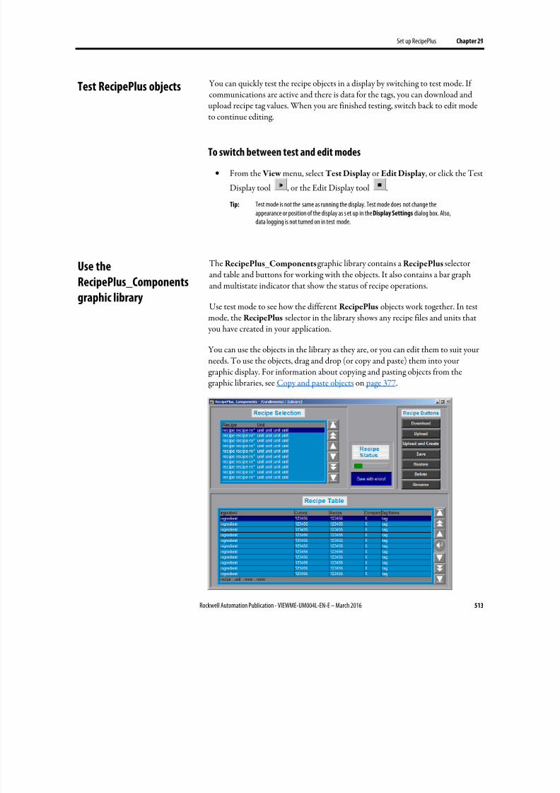
8/17/2019 FactoryTalk® View Machine Edition User's Guide
http://slidepdf.com/reader/full/factorytalk-view-machine-edition-users-guide 513/587
Set up RecipePlus Chapter 29
Rockwell Automation Publication - VIEWME-UM004L-EN-E – March 2016 513
You can quickly test the recipe objects in a display by switching to test mode. Ifcommunications are active and there is data for the tags, you can download andupload recipe tag values. When you are finished testing, switch back to edit modeto continue editing.
To switch between test and edit modes
• From the View menu, select Test Display or Edit Display , or click the Test
Display tool , or the Edit Display tool .
Tip: Test mode is not the same as running the display. Test mode does not change theappearance or position of the display as s et up in the Display Settings dialog box. Also,data logging is not turned on in test mode.
The RecipePlus_Components graphic library contains a RecipePlus selectorand table and buttons for working with the objects. It also contains a bar graphand multistate indicator that show the status of recipe operations.
Use test mode to see how the different RecipePlus objects work together. In testmode, the RecipePlus selector in the library shows any recipe files and units that you have created in your application.
You can use the objects in the library as they are, or you can edit them to suit yourneeds. To use the objects, drag and drop (or copy and paste) them into your
graphic display. For information about copying and pasting objects from thegraphic libraries, see Copy and paste objects on page 377.
Test RecipePlus objects
Use the
RecipePlus_Components
graphic library
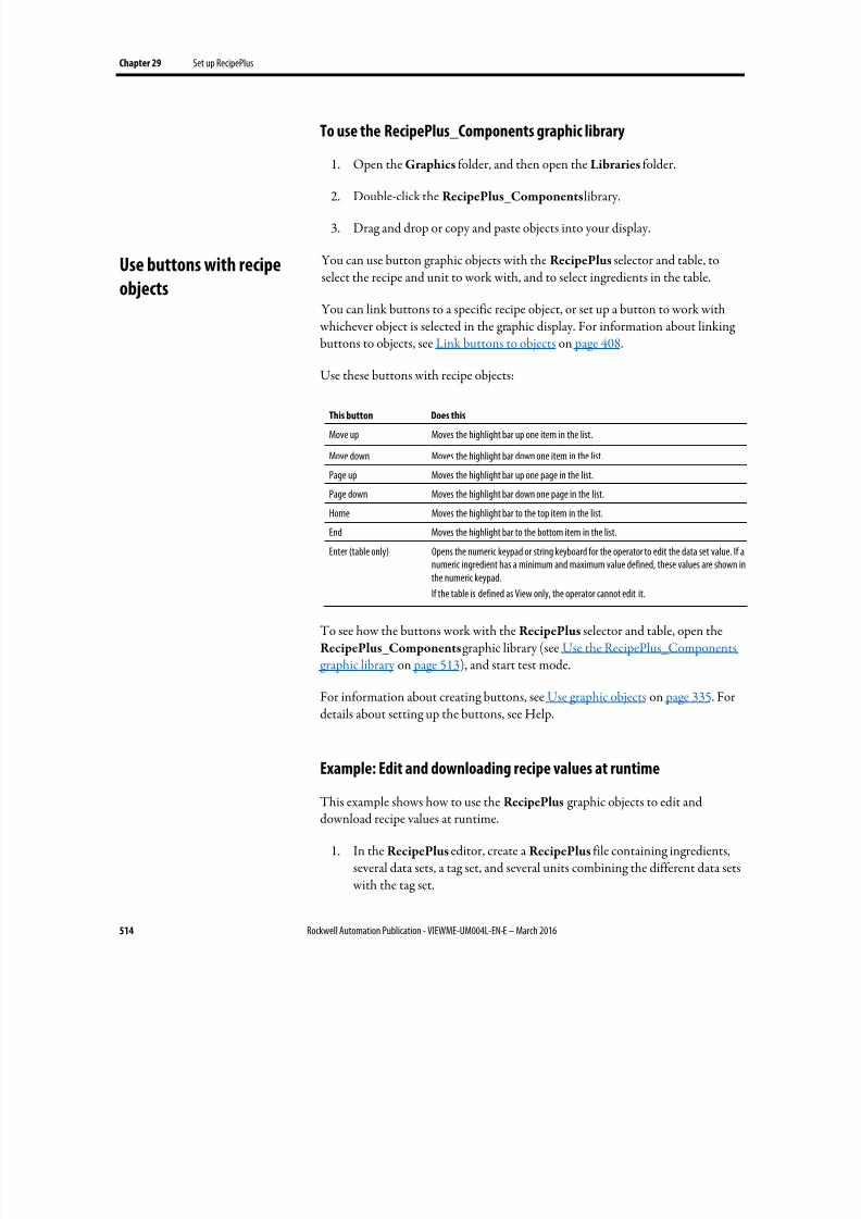
8/17/2019 FactoryTalk® View Machine Edition User's Guide
http://slidepdf.com/reader/full/factorytalk-view-machine-edition-users-guide 514/587
Chapter 29 Set up RecipePlus
514 Rockwell Automation Publication - VIEWME-UM004L-EN-E – March 2016
To use the RecipePlus_Components graphic library
1. Open the Graphics folder, and then open the Libraries folder.
2.
Double-click the RecipePlus_Components library.
3. Drag and drop or copy and paste objects into your display.
You can use button graphic objects with the RecipePlus selector and table, toselect the recipe and unit to work with, and to select ingredients in the table.
You can link buttons to a specific recipe object, or set up a button to work with whichever object is selected in the graphic display. For information about linkingbuttons to objects, see Link buttons to objects on page 408.
Use these buttons with recipe objects:
This button Does this
Move up Moves the highlight bar up one item in the list.
Move down Moves the highlight bar down one item in the list.
Page up Moves the highlight bar up one page in the list.
Page down Moves the highlight bar down one page in the list.
Home Moves the highlight bar to the top item in the list.
End Moves the highlight bar to the bottom item in the list.
Enter (table only) Opens the numeric keypad or string keyboard for the operator to edit the data set value. If a
numeric ingredient has a minimum and maximum value defined, these values are shown inthe numeric keypad.
If the table is defined as View only, the operator cannot edit it.
To see how the buttons work with the RecipePlus selector and table, open theRecipePlus_Components graphic library (see Use the RecipePlus_Componentsgraphic library on page 513), and start test mode.
For information about creating buttons, see Use graphic objects on page 335. Fordetails about setting up the buttons, see Help.
Example: Edit and downloading recipe values at runtime
This example shows how to use the RecipePlus graphic objects to edit anddownload recipe values at runtime.
1. In the RecipePlus editor, create a RecipePlus file containing ingredients,several data sets, a tag set, and several units combining the different data sets with the tag set.
Use buttons with recipe
objects
8/17/2019 FactoryTalk® View Machine Edition User's Guide
http://slidepdf.com/reader/full/factorytalk-view-machine-edition-users-guide 515/587
Set up RecipePlus Chapter 29
Rockwell Automation Publication - VIEWME-UM004L-EN-E – March 2016 515
2. Open the RecipePlus_Componentslibrary.
3. Start test mode.
4.
Use the move up and move down buttons next to the RecipePlus selectorto highlight a unit in the selector, and then press the Restore button.
The unit’s ingredients are shown in the RecipePlus table, with the data set
values in the Recipe column.
5. Use the move up and move down buttons next to the RecipePlus table toselect an ingredient, and then press the Enter button.
The numeric pop-up keypad opens, showing the minimum and maximum
values for the ingredient. If the ingredient is a string ingredient, the string
pop-up keyboard opens.
6. Type a new value for the ingredient, and then press Enter.
The new value is shown in the Recipe column.
7. Press the Save button to save the new value.
8. Press the Download button to write all the values in the Recipe column tothe tags associated with the ingredients.
The values are downloaded to the data source.
Use the RecipePlus Editor in FactoryTalk View Studio to view data values thathave been saved at runtime.
The operator can save tag values at runtime by uploading to an existing data set orto a new data set. The operator can also edit data set values in the RecipePlus table and save the edited values (unless the table is View only).
If recipe files are stored with the HMI project, changes are saved in the .mer file.To view the changes in FactoryTalk View Studio, convert the .mer file to an .med
file. For more information about converting the runtime application file, seeConvert runtime application files to development applications on page 227.
To view data values in modified recipe files
1. If recipe files are stored outside of the HMI project, do one of the following:
View data values that are
saved at runtime

8/17/2019 FactoryTalk® View Machine Edition User's Guide
http://slidepdf.com/reader/full/factorytalk-view-machine-edition-users-guide 516/587
Chapter 29 Set up RecipePlus
516 Rockwell Automation Publication - VIEWME-UM004L-EN-E – March 2016
• Add the recipe file (*.rpp) that you saved at runtime into theapplication using Add Component Into Application (for details, seeAdd components into an application on page 299).
•
If the recipe file already exists in the application, you can just copy themodified file back into the application’s RecipePlus folder. (For the path to the RecipePlus folder, see Store files outside the HMI project on page 509.)
2.
If recipe files are stored with the HMI project, and you have not alreadydone so, convert the runtime application file to a development application,as described on Convert runtime application files to developmentapplications on page 227.
3. In the Explorer window in FactoryTalk View Studio, double-click the
modified recipe file.
The RecipePlus Editor opens.
4. Click the Ingredients tab.
5. If the data set you want to view is not visible, scroll right to see more datasets.

8/17/2019 FactoryTalk® View Machine Edition User's Guide
http://slidepdf.com/reader/full/factorytalk-view-machine-edition-users-guide 517/587
Rockwell Automation Publication - VIEWME-UM004L-EN-E – March 2016 517
Chapter 30
Use macros
This chapter describes:
• Use macros to assign values to tags
• Use the Macros editor
• When to use macros
•
Running macros when tags or expressions change value• Where to assign macros
A macro is a list of tag assignments stored in a text file, in the format<tag>=<value>. Each assignment assigns a value to a tag. The value can be in theform of another tag, an expression, a numeric constant, or a string.
Examples: Use macros to set tag values
Tag1 = 8
Sets the value of Tag1 to 8.
Tank1\Message = "Tank1 overflow"Sets the string tag Tank1\Message to Tank1 overflow.
Tag1 = Tag2Sets the value of Tag1 to be the same as Tag2.
Tag1 = Tag1 + 1Increases the value of Tag1 by 1.
Tag1 = if (Tag2 < Tag1) then 4 else 3Performs the if-then-else calculation and stores the result in Tag1.
1Pump = {Industry-2} + {2Pump}Adds the values of Industry-2 and 2Pump and stores the result in 1Pump.
Brackets surround Industry-2 because of the dash in the name. Brackets surround2Pump because the name starts with a number. No brackets are used for 1Pumpbecause this name is on the left side of the equal sign.
For more information about expression syntax, see Use expressions on page 435.
Use macros to assign values
to tags
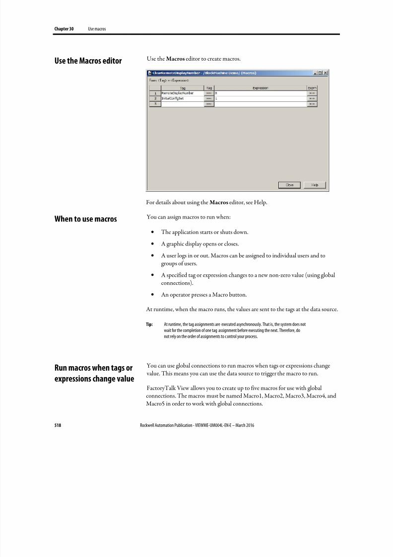
8/17/2019 FactoryTalk® View Machine Edition User's Guide
http://slidepdf.com/reader/full/factorytalk-view-machine-edition-users-guide 518/587
Chapter 30 Use macros
518 Rockwell Automation Publication - VIEWME-UM004L-EN-E – March 2016
Use the Macros editor to create macros.
For details about using the Macros editor, see Help.
You can assign macros to run when:
• The application starts or shuts down.
• A graphic display opens or closes.
• A user logs in or out. Macros can be assigned to individual users and togroups of users.
• A specified tag or expression changes to a new non-zero value (using globalconnections).
• An operator presses a Macro button.
At runtime, when the macro runs, the values are sent to the tags at the data source.
Tip: At runtime, the tag assignments are executed asynchronously. That is, the system does notwait for the completion of one tag assignment before executing the next. Therefore, donot rely on the order of assignments to c ontrol your process.
You can use global connections to run macros when tags or expressions change value. This means you can use the data source to trigger the macro to run.
FactoryTalk View allows you to create up to five macros for use with globalconnections. The macros must be named Macro1, Macro2, Macro3, Macro4, andMacro5 in order to work with global connections.
Use the Macros editor
When to use macros
Run macros when tags or
expressions change value
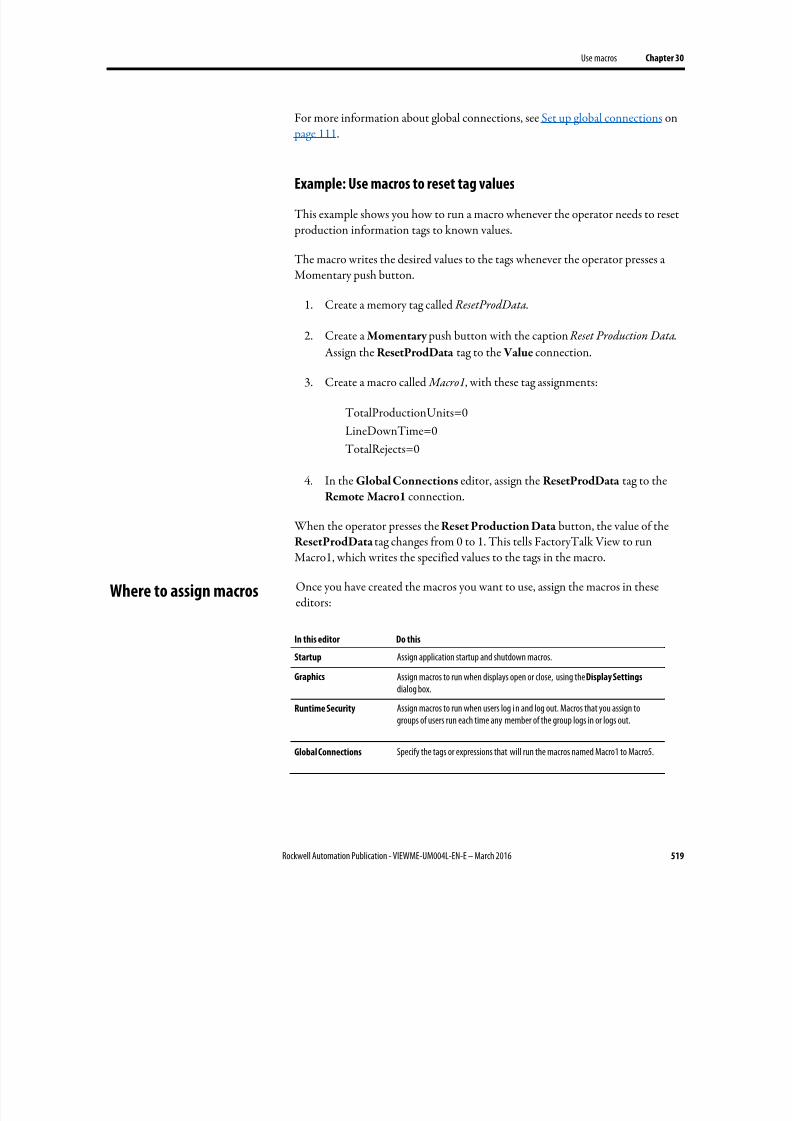
8/17/2019 FactoryTalk® View Machine Edition User's Guide
http://slidepdf.com/reader/full/factorytalk-view-machine-edition-users-guide 519/587
Use macros Chapter 30
Rockwell Automation Publication - VIEWME-UM004L-EN-E – March 2016 519
For more information about global connections, see Set up global connections on page 111.
Example: Use macros to reset tag values
This example shows you how to run a macro whenever the operator needs to reset production information tags to known values.
The macro writes the desired values to the tags whenever the operator presses aMomentary push button.
1. Create a memory tag called ResetProdData.
2. Create a Momentary push button with the caption Reset Production Data.
Assign the ResetProdData tag to the Value connection.
3. Create a macro called Macro1, with these tag assignments:
TotalProductionUnits=0
LineDownTime=0
TotalRejects=0
4. In the Global Connections editor, assign the ResetProdData tag to theRemote Macro1 connection.
When the operator presses the Reset Production Data button, the value of theResetProdData tag changes from 0 to 1. This tells FactoryTalk View to runMacro1, which writes the specified values to the tags in the macro.
Once you have created the macros you want to use, assign the macros in theseeditors:
In this editor Do this
Startup Assign application startup and shutdown macros.
Graphics Assign macros to run when displays open or close, using the Display Settings
dialog box.
Runtime Security Assign macros to run when users log i n and log out. Macros that you assign togroups of users run each time any member of the group logs in or logs out.
Global Connections Specify the tags or expressions that will run the macros named Macro1 to Macro5.
Where to assign macros

8/17/2019 FactoryTalk® View Machine Edition User's Guide
http://slidepdf.com/reader/full/factorytalk-view-machine-edition-users-guide 520/587
Chapter 30 Use macros
520 Rockwell Automation Publication - VIEWME-UM004L-EN-E – March 2016
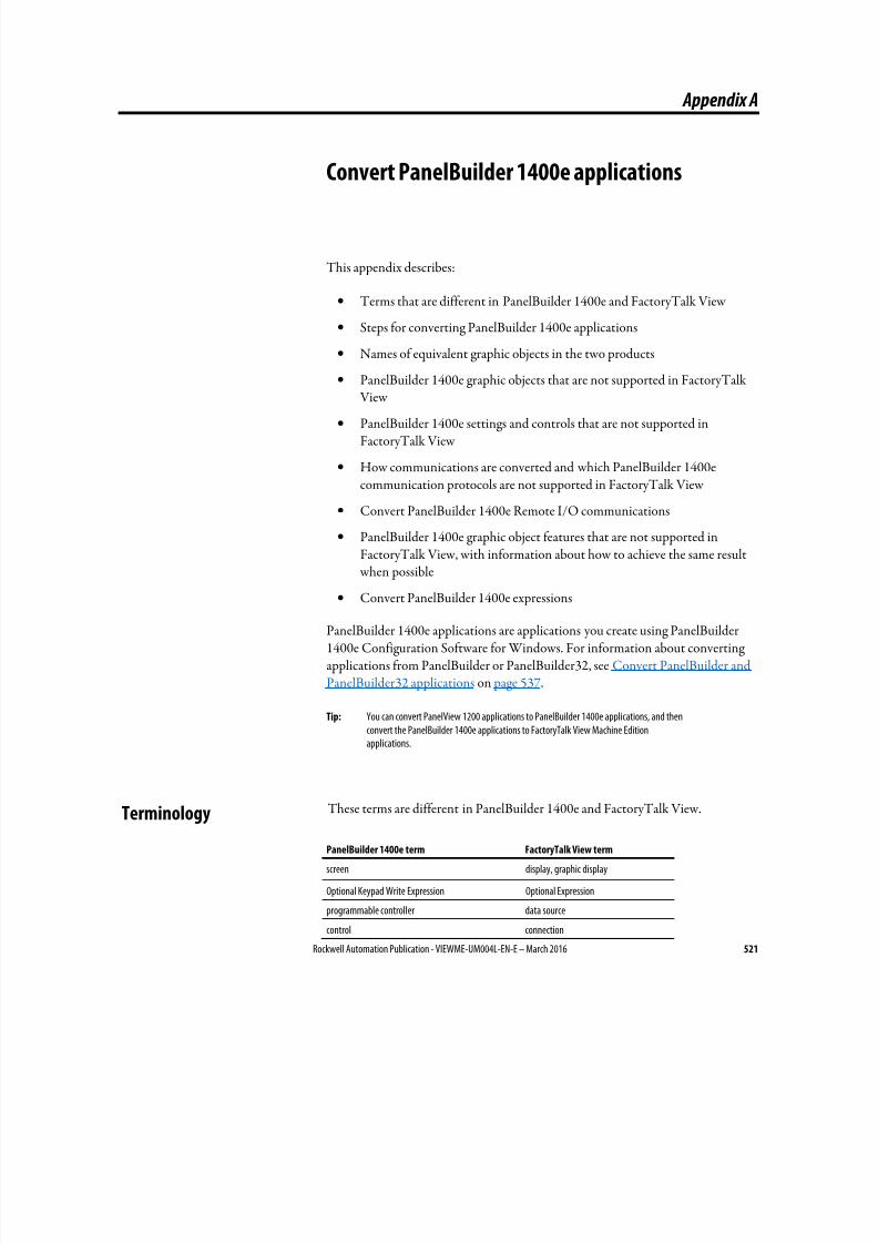
8/17/2019 FactoryTalk® View Machine Edition User's Guide
http://slidepdf.com/reader/full/factorytalk-view-machine-edition-users-guide 521/587
Rockwell Automation Publication - VIEWME-UM004L-EN-E – March 2016 521
Appendix A
Convert PanelBuilder 1400e applications
This appendix describes:
• Terms that are different in PanelBuilder 1400e and FactoryTalk View
• Steps for converting PanelBuilder 1400e applications
• Names of equivalent graphic objects in the two products
•
PanelBuilder 1400e graphic objects that are not supported in FactoryTalk View
• PanelBuilder 1400e settings and controls that are not supported inFactoryTalk View
• How communications are converted and which PanelBuilder 1400ecommunication protocols are not supported in FactoryTalk View
• Convert PanelBuilder 1400e Remote I/O communications
• PanelBuilder 1400e graphic object features that are not supported inFactoryTalk View, with information about how to achieve the same result
when possible• Convert PanelBuilder 1400e expressions
PanelBuilder 1400e applications are applications you create using PanelBuilder1400e Configuration Software for Windows. For information about convertingapplications from PanelBuilder or PanelBuilder32, see Convert PanelBuilder andPanelBuilder32 applications on page 537.
Tip: You can convert PanelView 1200 applications to PanelBuilder 1400e applications, and thenconvert the PanelBuilder 1400e applications to FactoryTalk View Machine Editionapplications.
These terms are different in PanelBuilder 1400e and FactoryTalk View.
PanelBuilder 1400e term FactoryTalk View term
screen display, graphic display
Optional Keypad Write Expression Optional Expression
programmable controller data source
control connection
Terminology
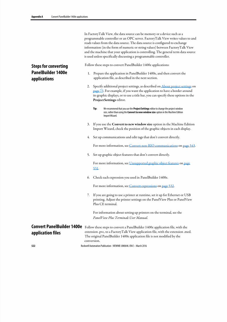
8/17/2019 FactoryTalk® View Machine Edition User's Guide
http://slidepdf.com/reader/full/factorytalk-view-machine-edition-users-guide 522/587
Appendix A Convert PanelBuilder 1400e applications
522 Rockwell Automation Publication - VIEWME-UM004L-EN-E – March 2016
In FactoryTalk View, the data source can be memory or a device such as a programmable controller or an OPC server. FactoryTalk View writes values to andreads values from the data source. The data source is configured to exchangeinformation (in the form of numeric or string values) between FactoryTalk Viewand the machine that your application is controlling. The general term data sourceis used unless specifically discussing a programmable controller.
Follow these steps to convert PanelBuilder 1400e applications:
1. Prepare the application in PanelBuilder 1400e, and then convert theapplication file, as described in the next section.
2.
Specify additional project settings, as described on About project settings on page 73. For example, if you want the application to have a border aroundits graphic displays, or to use a title bar, you can specify these options in the
Project Settings editor.
Tip: We recommend that you use the Project Settings editor to change the project windowsize, rather than using the Convert to new window size option in the Machine EditionImport Wizard.
3. If you use the Convert to new window size option in the Machine EditionImport Wizard, check the position of the graphic objects in each display.
4. Set up communications and edit tags that don’t convert directly.
For more information, see Convert non-RIO communications on page 543.
5. Set up graphic object features that don’t convert directly.
For more information, see Unsupported graphic object features on page
531.
6. Check each expression you used in PanelBuilder 1400e.
For more information, see Convert expressions on page 532.
7. If you are going to use a printer at runtime, set it up for Ethernet or USB
printing. Adjust the printer settings on the PanelView Plus or PanelViewPlus CE terminal.
For information about setting up printers on the terminal, see the
PanelView Plus Terminals User Manual .
Follow these steps to convert a PanelBuilder 1400e application file, with theextension .pvc, to a FactoryTalk View application file, with the extension .med.The original PanelBuilder 1400e application file is not modified by theconversion.
Steps for converting
PanelBuilder 1400e
applications
Convert PanelBuilder 1400e
application files
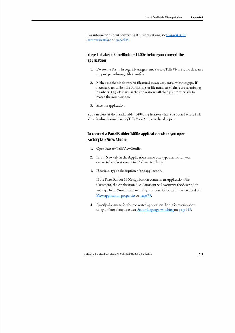
8/17/2019 FactoryTalk® View Machine Edition User's Guide
http://slidepdf.com/reader/full/factorytalk-view-machine-edition-users-guide 523/587
Convert PanelBuilder 1400e applications Appendix A
Rockwell Automation Publication - VIEWME-UM004L-EN-E – March 2016 523
For information about converting RIO applications, see Convert RIOcommunications on page 529.
Steps to take in PanelBuilder 1400e before you convert the
application
1. Delete the Pass-Through file assignment. FactoryTalk View Studio does notsupport pass-through file transfers.
2. Make sure the block transfer file numbers are sequential without gaps. Ifnecessary, renumber the block transfer file numbers so there are no missingnumbers. Tag addresses in the application will change automatically tomatch the new number.
3.
Save the application.
You can convert the PanelBuilder 1400e application when you open FactoryTalk View Studio, or once FactoryTalk View Studio is already open.
To convert a PanelBuilder 1400e application when you open
FactoryTalk View Studio
1. Open FactoryTalk View Studio.
2.
In the New tab, in the Application name box, type a name for yourconverted application, up to 32 characters long.
3. If desired, type a description of the application.
If the PanelBuilder 1400e application contains an Application File
Comment, the Application File Comment will overwrite the description
you type here. You can add or change the description later, as described on
View application properties on page 79.
4.
Specify a language for the converted application. For information aboutusing different languages, see Set up language switching on page 199.
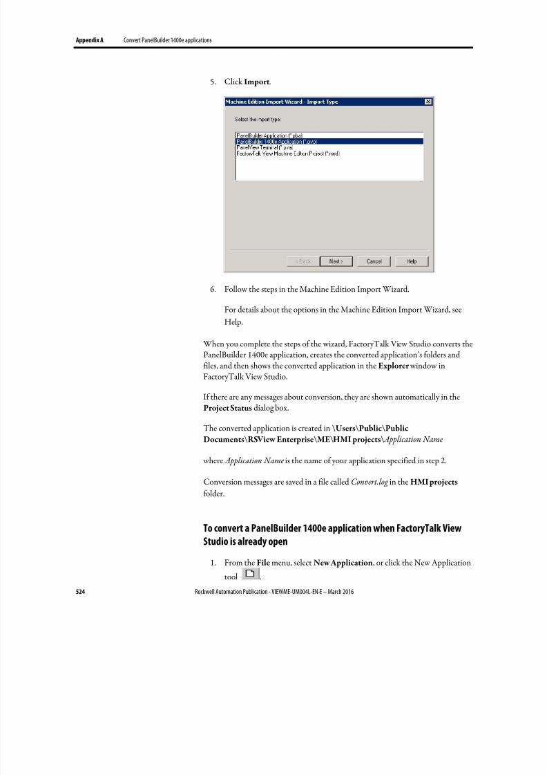
8/17/2019 FactoryTalk® View Machine Edition User's Guide
http://slidepdf.com/reader/full/factorytalk-view-machine-edition-users-guide 524/587
Appendix A Convert PanelBuilder 1400e applications
524 Rockwell Automation Publication - VIEWME-UM004L-EN-E – March 2016
5. Click Import.
6. Follow the steps in the Machine Edition Import Wizard.
For details about the options in the Machine Edition Import Wizard, see
Help.
When you complete the steps of the wizard, FactoryTalk View Studio converts thePanelBuilder 1400e application, creates the converted application’s folders andfiles, and then shows the converted application in the Explorer window inFactoryTalk View Studio.
If there are any messages about conversion, they are shown automatically in theProject Status dialog box.
The converted application is created in \Users\Public\Public
Documents\RSView Enterprise\ME\HMI projects\ Application Name
where Application Name is the name of your application specified in step 2.
Conversion messages are saved in a file called Convert.log in the HMI projects folder.
To convert a PanelBuilder 1400e application when FactoryTalk View
Studio is already open
1. From the File menu, select New Application, or click the New Application
tool .
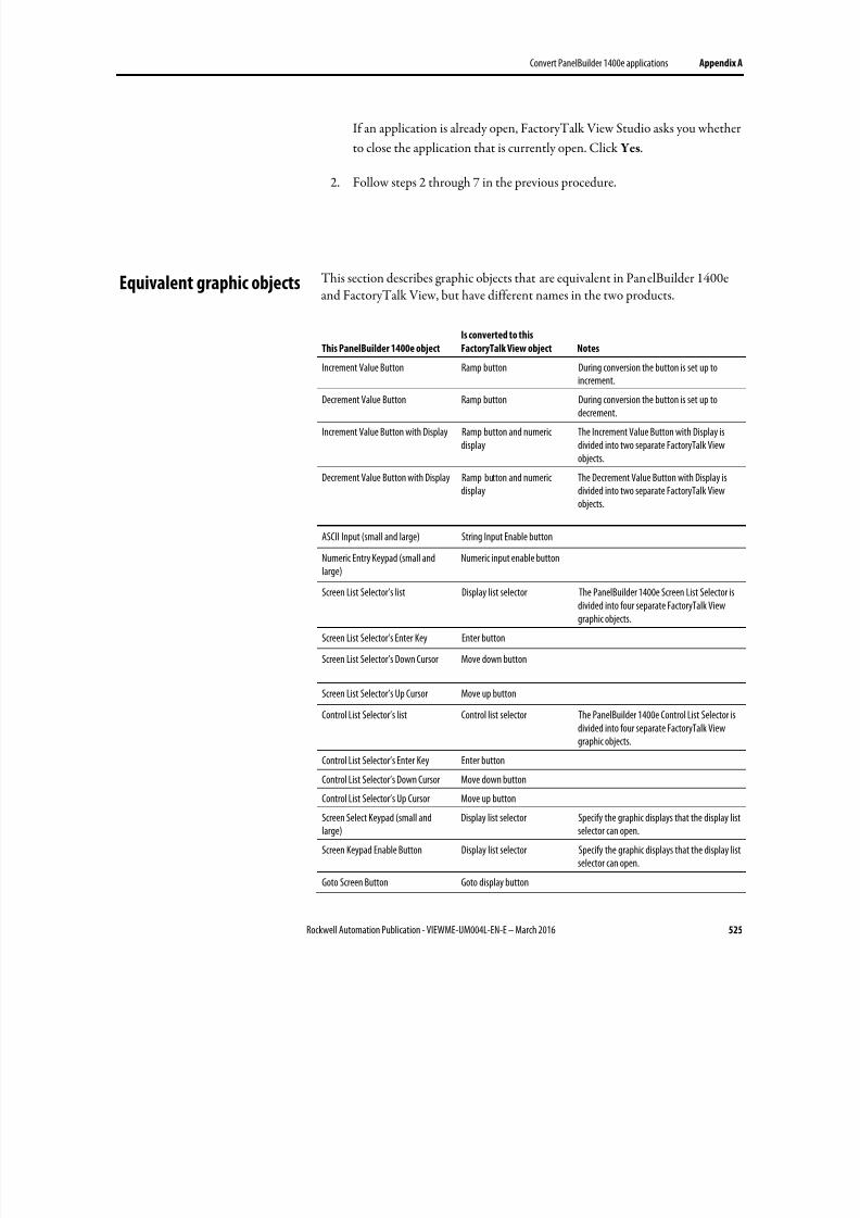
8/17/2019 FactoryTalk® View Machine Edition User's Guide
http://slidepdf.com/reader/full/factorytalk-view-machine-edition-users-guide 525/587
Convert PanelBuilder 1400e applications Appendix A
Rockwell Automation Publication - VIEWME-UM004L-EN-E – March 2016 525
If an application is already open, FactoryTalk View Studio asks you whether
to close the application that is currently open. Click Yes.
2.
Follow steps 2 through 7 in the previous procedure.
This section describes graphic objects that are equivalent in PanelBuilder 1400eand FactoryTalk View, but have different names in the two products.
This PanelBuilder 1400e object
Is converted to this
FactoryTalk View object Notes
Increment Value Button Ramp button During conversion the button is set up to
increment.
Decrement Value Button Ramp button During conversion the button is set up todecrement.
Increment Value Button with Display Ramp button and numericdisplay
The Increment Value Button with Display isdivided into two separate FactoryTalk Viewobjects.
Decrement Value Button with Display Ramp button and numericdisplay
The Decrement Value Button with Display isdivided into two separate FactoryTalk Viewobjects.
ASCII Input (small and large) String Input Enable button
Numeric Entry Keypad (small andlarge)
Numeric input enable button
Screen List Selector’s list Display list selector The PanelBuilder 1400e Screen List Selector isdivided into four separate FactoryTalk Viewgraphic objects.
Screen List Selector’s Enter Key Enter button
Screen List Selector’s Down Cursor Move down button
Screen List Selector’s Up Cursor Move up button
Control List Selector’s list Control list selector The PanelBuilder 1400e Control List Selector isdivided into four separate FactoryTalk Viewgraphic objects.
Control List Selector’s Enter Key Enter button
Control List Selector’s Down Cursor Move down button
Control List Selector’s Up Cursor Move up button
Screen Select Keypad (small andlarge)
Display list selector Specify the graphic displays that the display listselector can open.
Screen Keypad Enable Button Display list selector Specify the graphic displays that the display listselector can open.
Goto Screen Button Goto display button
Equivalent graphic objects
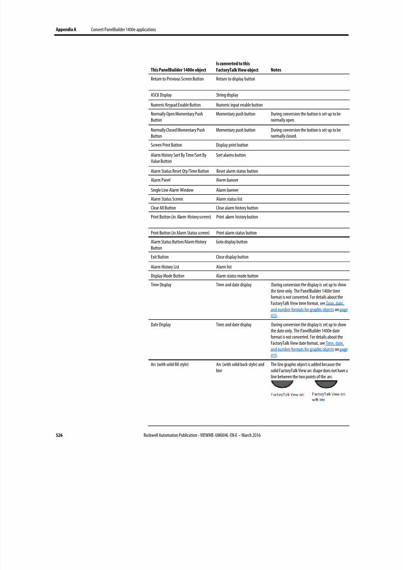
8/17/2019 FactoryTalk® View Machine Edition User's Guide
http://slidepdf.com/reader/full/factorytalk-view-machine-edition-users-guide 526/587
Appendix A Convert PanelBuilder 1400e applications
526 Rockwell Automation Publication - VIEWME-UM004L-EN-E – March 2016
This PanelBuilder 1400e object
Is converted to this
FactoryTalk View object Notes
Return to Previous Screen Button Return to display button
ASCII Display String display
Numeric Keypad Enable Button Numeric input enable button
Normally Open Momentary PushButton
Momentary push button During conversion the button is set up to benormally open.
Normally Closed Momentary PushButton
Momentary push button During conversion the button is set up to benormally closed.
Screen Print Button Display print button
Alarm History Sort By Time/Sort ByValue Button
Sort alarms button
Alarm Status Reset Qty/Time Button Reset alarm status button
Alarm Panel Alarm banner
Single Line Alarm Window Alarm banner
Alarm Status Screen Alarm status list
Clear All Button Clear alarm history button
Print Button (in Alarm History screen) Print alarm history button
Print Button (in Alarm Status screen) Print alarm status button
Alarm Status Button/Alarm HistoryButton
Goto display button
Exit Button Close display button
Alarm History List Alarm list
Display Mode Button Alarm status mode button
Time Display Time and date display During conversion the display is set up to showthe time only. The PanelBuilder 1400e timeformat is not converted. For details about theFactoryTalk View time format, see Time, date,and number formats for graphic objects on page415.
Date Display Time and date display During conversion the display is set up to showthe date only. The PanelBuilder 1400e dateformat is not converted. For details about theFactoryTalk View date format, see Time, date,and number formats for graphic objects on page
415.
Arc (with solid fill style) Arc (with solid back style) andline
The line graphic object is added because thesolid FactoryTalk View arc shape does not have aline between the two points of the arc.
8/17/2019 FactoryTalk® View Machine Edition User's Guide
http://slidepdf.com/reader/full/factorytalk-view-machine-edition-users-guide 527/587
Convert PanelBuilder 1400e applications Appendix A
Rockwell Automation Publication - VIEWME-UM004L-EN-E – March 2016 527
These PanelBuilder 1400e objects are not supported in FactoryTalk View:
•
Scrolling List (includes Cursor List, Multistate Indicator Object List, LocalMessage Object List, Numeric Data Display Object List)
• Set Bit Cursor Point
This section describes PanelBuilder 1400e settings and controls that are not usedin FactoryTalk View.
Controls for transferring runtime application files
PanelBuilder 1400e uses these optional controls for transferring files to theruntime terminal:
• Transfer Inhibit control
• Transfer Request control
• Transfer Status control
These controls are not necessary in FactoryTalk View because the ME TransferUtility allows you to transfer the runtime project file while running a project onthe runtime terminal.
Settings and controls for alarms
FactoryTalk View does not use these PanelBuilder 1400e features and settings tomanage alarms:
• Alarm relays
• Bit alarm acknowledgement
• Remote Alarm Operation Hold Time. The PanelBuilder 1400e RemoteAlarm Ack Control Hold Time will be used for all alarm hold times. You
can change the hold time in the FactoryTalk View Alarm Setup editor, inthe Advanced tab.
• Remote Alarm Control Delay Time. In FactoryTalk View, if an Ack
connection is assigned, when an alarm is acknowledged the Ack connectionis set immediately, without waiting for a delay time.
FactoryTalk View does not use these PanelBuilder 1400e controls to managealarms:
Unsupported graphic
objects
Unsupported settings and
controls
8/17/2019 FactoryTalk® View Machine Edition User's Guide
http://slidepdf.com/reader/full/factorytalk-view-machine-edition-users-guide 528/587
Appendix A Convert PanelBuilder 1400e applications
528 Rockwell Automation Publication - VIEWME-UM004L-EN-E – March 2016
• PLC Controlled Relay control
• PLC Controlled Audio control
• Acknowledge to PLC control (if the Alarm Acknowledge to PLC option isset to Bit)
Invalid characters in screen names
Characters in PanelBuilder 1400e screen names that are not supported inFactoryTalk View are replaced with the underscore character.
Screen security settings
PanelBuilder 1400e screen security settings are not converted, becauseFactoryTalk View uses a different method to assign security to graphic displays.For information about setting up security in FactoryTalk View, see Set up security on page 175.
Block tags
Block tags are not supported in FactoryTalk View. Block tags that are monitoredfor alarms in your PanelBuilder 1400e application are converted to bit arrays. For
information about monitoring bit arrays for alarm conditions, see Set up alarms on page 119.
This section describes how communications that do not use Remote I/O (RIO)are converted.
FactoryTalk View does not use nodes for communications. Nodes are convertedto RSLinx topics. Topics are then converted into device shortcuts, to run withRSLinx Enterprise. You must have both RSLinx Classic and RSLinx Enterpriseinstalled to make this two-step conversion.
Tags are converted to HMI device tags and RSLinx aliases. The Unsolicited_Msgs
node is not converted.
If you import an application multiple times, delete the device shortcuts in RSLinxEnterprise before re-importing. Otherwise, multiple unused device shortcuts willbe created in RSLinx Enterprise.
For more information about setting up communications, see Set upcommunications on page 81.
Convert non-RIO
communications
8/17/2019 FactoryTalk® View Machine Edition User's Guide
http://slidepdf.com/reader/full/factorytalk-view-machine-edition-users-guide 529/587
Convert PanelBuilder 1400e applications Appendix A
Rockwell Automation Publication - VIEWME-UM004L-EN-E – March 2016 529
For information about converting RIO communications, see Convert RIOcommunications on page 529.
Unsupported tag data types
These tag data types are not supported in FactoryTalk View:
• Bit Position
• 1-BCD, 2-BCD, 5-BCD, 6-BCD, 7-BCD, 8-BCD
• BIN3, BIN4, BIN6, BIN8 (used with Modbus communications)
Tags that use these data types are converted to analog HMI tags with the Defaultdata type. The Default data type uses floating point values.
For Bit Position data types, use the bitwise expression operators to show data thatdoes not reference supported lengths. For more information, see the RockwellAutomation Knowledgebase.
To open the Knowledgebase
• In FactoryTalk View Studio, from the Help menu, select Rockwell
Automation on the Web > Rockwell Automation KnowledgeBase.
For information about using bitwise expression operators, see Bitwise operators on
page 442.
Unsupported initial values
Device tags in FactoryTalk View do not use initial values. Memory tags areconverted with their initial values.
You can use Remote I/O (RIO) communications on the PanelView Plus, andPanelView Plus CE runtime platforms.
Tip: For PanelView Plus 7 and PanelView Plus 6 terminals, you need a third party RIO toEthernet gateway module for RIO communications. For more information, see Answer ID490889 in Rockwell Automation Knowledgebase.
RIO communications are not supported for the applications that run on a personal computer. However, you can test run your RIO applications on thedevelopment computer.
Convert RIO
communications
8/17/2019 FactoryTalk® View Machine Edition User's Guide
http://slidepdf.com/reader/full/factorytalk-view-machine-edition-users-guide 530/587
Appendix A Convert PanelBuilder 1400e applications
530 Rockwell Automation Publication - VIEWME-UM004L-EN-E – March 2016
To convert an RIO application from PanelBuilder 1400e to FactoryTalk
View
1.
Convert the application.
For more information, see Convert PanelBuilder 1400e application files on
page 522.
2. Open the RSLinx Enterprise data server, and then double-clickCommunication Setup.
3. In the Communication Setup editor, add an RIO driver.
• For PanelView Plus 400 and 600 terminals, use the 2711P-RN1 driver.
•
For all other PanelView Plus or PanelView Plus CE terminals, use the2711P-RN6 driver.
For information about adding drivers in RSLinx, see RSLinx Help.
4. Expand the RIO tree, right-click RIO Data, and then click Configure RIO.
5. In the RIO Configuration dialog box, right-click RIO, and then clickImport.
6. Browse to the location of the RIO configuration file.
The file is saved in the root of the application’s directory.
7. In the Communications Setup editor, create a device shortcut that pointsto the RIO data device.
For information about creating a device shortcut, see RSLinx Help.
8. Apply the shortcut to the RIO driver.
9. Correct any invalid RIO configurations. Invalid RIO configurations arehighlighted with red "x" icons.
Note: If red "x" icons appear after you im port the RIO .xml file, you can fix block tags in theCommunication Setup editor in FactoryTalk View. The length of block tags must be thesame for Read and Write pairs sharing the same rack, group, and slot.
10. Create an alias for any data that is not a 16-bit integer or bit.
11. Save the converted RIO application.
8/17/2019 FactoryTalk® View Machine Edition User's Guide
http://slidepdf.com/reader/full/factorytalk-view-machine-edition-users-guide 531/587
Convert PanelBuilder 1400e applications Appendix A
Rockwell Automation Publication - VIEWME-UM004L-EN-E – March 2016 531
Important: RIO configurations are not saved with the application when you exitFactoryTalk View Studio. However, they are backed up with theapplication in the Application Manager.
For information about handling multiple applications with different RIO
settings, see the Rockwell Automation Knowledgebase.For information about using the Application Manager, see Rename, copy,delete, back up, and restore applications on page 73.
A PanelBuilder 1400e RIO tag will be converted to an HMI memory tag and anerror will be logged to the conversion log file if the RIO tag:
• Has a blank address.
• Has a data type of 1-BCD, 2-BCD, 3-BCD, 5-BCD, 6-BCD, or 7-BCD.
•
Has a data type of Bit Position and its address does not reference a single bit.
• Float has a data type of Float and its address has a bit offset assigned that isnot 0.
• Has a data type of Long Integer or 8 Digit BCD, its address has a bit offsetassigned that is not 0, and its length or range is greater than (32 - Start Bit ).
• Has a tag type of Block.
• Has an invalid PanelBuilder 1400e address or references an undefined rack.
This section describes features of PanelBuilder 1400e graphic objects that are not
supported in FactoryTalk View. The Notes column provides additionalinformation and describes methods for achieving the same result when possible.
Graphic object
Unsupported feature in FactoryTalk
View Notes
Image text, arc, ellipse, line,panel, rectangle, wedge
Blinking wallpaper objects If you want an object to blink at runtime, unlock thewallpaper.
In FactoryTalk View, all of the listed objects except imagesuse color animation to blink. For details, see Set up coloranimation on page 425.
Color images do not blink. Monochrome images use theBlink property to blink.
Numeric Display Polarity If a PanelBuilder 1400e application was set up with thePolarity control requiring a negative number to show theminus sign, the numeric display will not work properly afterthe application is converted to FactoryTalk View MachineEdition.
Numeric Input Cursor Point,Numeric Data Display
Fixed Position and PLC Controlleddecimal display options
Use an expression to achieve the same result. Assign theexpression to the object’s Value connection. For informationabout expressions, see Use expressions on page 435.
Unsupported PanelBuilder
1400e RIO tags
Unsupported graphic object
features
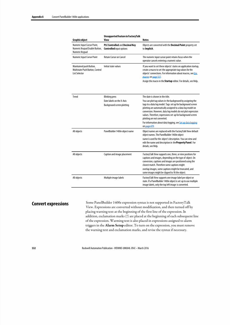
8/17/2019 FactoryTalk® View Machine Edition User's Guide
http://slidepdf.com/reader/full/factorytalk-view-machine-edition-users-guide 532/587
Appendix A Convert PanelBuilder 1400e applications
532 Rockwell Automation Publication - VIEWME-UM004L-EN-E – March 2016
Graphic object
Unsupported feature in FactoryTalk
View Notes
Numeric Input Cursor Point,Numeric Keypad Enable Button,Numeric Keypad
PLC Controlled and Decimal Key
Controlled input optionsObjects are converted with the Decimal Point property setto Implicit.
Numeric Input Cursor Point Retain Cursor on Cancel The numeric input cursor point retains focus when theoperator cancels entering a numeric value.
Maintained push Button,Multistate Push Button, ControlList Selector
Initial state values If you want to set these objects’ states on application startup,create a macro to set the appropriate tag values for theobjects’ connections. For information about macros, see Usemacros on page 517.
Assign the macro in the Startup editor. For details, see Help.
Trend Blinking pens
Date labels on the X-AxisBackground screen plotting
The date is shown in the title.
You can plot tag values in the background by assigning thetags to a data log model. Tags set up for background screenplotting are automatically assigned to a data log model onconversion. However, data log models do not plot expressionvalues. Therefore, expressions set up for background screenplotting are not converted.
For information about data logging, see Set up data logging on page 479.
All objects PanelBuilder 1400e object name Object names are replaced with the FactoryTalk View defaultobject names. The PanelBuilder 1400e object
name is used for the object’s description. You can view andedit the name and description in the Property Panel. Fordetails, see Help.
All objects Caption and image placement FactoryTalk View supports one, three, or nine positions forcaptions and images, depending on the type of object. Onconversion, captions and images are positioned using theclosest match. Therefore some captions might
overlap images, some captions might be truncated, andsome images might be clipped to fit the object.
All objects Multiple image labels FactoryTalk View supports one image label per object orstate. If a PanelBuilder 1400e object is set up to use multipleimage labels, only the top left image is converted.
Some PanelBuilder 1400e expression syntax is not supported in FactoryTalk View. Expressions are converted without modification, and then turned off by placing warning text at the beginning of the first line of the expression. Inaddition, exclamation marks (!) are placed at the beginning of each subsequent lineof the expression. Warming text is also placed in expressions assigned to alarmtriggers in the Alarm Setup editor. To turn on the expression, you must removethe warning text and exclamation marks, and revise the syntax if necessary.
Convert expressions

8/17/2019 FactoryTalk® View Machine Edition User's Guide
http://slidepdf.com/reader/full/factorytalk-view-machine-edition-users-guide 533/587
Convert PanelBuilder 1400e applications Appendix A
Rockwell Automation Publication - VIEWME-UM004L-EN-E – March 2016 533
The maximum expression length in FactoryTalk View is 16,000 characters. If aPanelBuilder 1400e expression contains more than 16,000 characters, the excesscharacters are not converted.
Some PanelBuilder 1400e objects support both tags and expressions. For theseobjects, if the text assigned to a connection could be valid syntax for both a tag andan expression, the connection is treated as an expression, and is therefore turnedoff.
For example, N20-0_String_64 could be the name of a tag, or it could be anexpression that subtracts "0_String_64" from the tag "N20." The text would beconverted as an expression, and turned off.
To turn on an expression
1. Select the object containing the expression.
2. Open the Property Panel, and then click the Connections tab.
3. In the Exprn column, click the Browse button beside the expression to turnon.
4. In the Expression editor, delete the warning text and exclamation marks.
5. Revise the expression, if necessary, using the tables in the following three
sections as guides.
6. Click Check Syntax .
For more information about using the Expression editor, see Use expressions on page 435 or Help.
Equivalent expression syntax
This table describes FactoryTalk View expression syntax that is equivalent toPanelBuilder 1400e syntax. When you edit the converted expressions, replace thePanelBuilder 1400e syntax with the FactoryTalk View equivalent.
Syntax that is not listed in this table or in the next section is okay the way it is.
Type of expression component or
operator PanelBuilder 1400e syntax FactoryTalk View syntax
Comment REM or ‘ !
Line continuation _ (underscore) Not needed.
Equality ( = ) EQ or ==
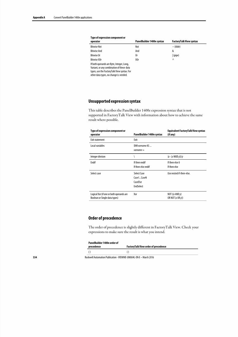
8/17/2019 FactoryTalk® View Machine Edition User's Guide
http://slidepdf.com/reader/full/factorytalk-view-machine-edition-users-guide 534/587
Appendix A Convert PanelBuilder 1400e applications
534 Rockwell Automation Publication - VIEWME-UM004L-EN-E – March 2016
Type of expression component or
operator PanelBuilder 1400e syntax FactoryTalk View syntax
Bitwise Not
Bitwise AndBitwise Or
Bitwise XOr
If both operands are Byte, Integer, Long,Variant, or any combination of these datatypes, use the FactoryTalk View syntax. Forother data types, no change is needed.
Not
AndOr
XOr
~ (tilde)
&| (pipe)
^
Unsupported expression syntax
This table describes the PanelBuilder 1400e expression syntax that is notsupported in FactoryTalk View with information about how to achieve the sameresult where possible.
Type of expression component or
operator PanelBuilder 1400e syntax
Equivalent FactoryTalk View syntax
(if any)
Exit statement Exit
Local variables DIM varname AS ...
varname =
Integer division \ ( x - ( x MOD y ))/ y
Endif If then endif
If then else endif
If then else 0
If then else
Select case Select Case
Case1...CaseN
CaseElse
EndSelect
Use nested if-then-else.
Logical Xor (if one or both operands areBoolean or Single data types)
Xor NOT (( x AND y )OR NOT ( x OR y ))
Order of precedence
The order of precedence is slightly different in FactoryTalk View. Check yourexpressions to make sure the result is what you intend.
PanelBuilder 1400e order of
precedence FactoryTalk View order of precedence
( ) ( )

8/17/2019 FactoryTalk® View Machine Edition User's Guide
http://slidepdf.com/reader/full/factorytalk-view-machine-edition-users-guide 535/587
Convert PanelBuilder 1400e applications Appendix A
Rockwell Automation Publication - VIEWME-UM004L-EN-E – March 2016 535
PanelBuilder 1400e order of
precedence FactoryTalk View order of precedence
- (negation) NOT, ~ (tilde)
*, / (floating point division) *, /, MOD, %, **, AND, &&, &, >>, <<\ (integer division) +, -, OR, ||, |, ^
MOD EQ, ==, NE, <>, LT, <, GT, >, LE, <=, GE, >=
+, - (subtraction)
=, <>, <, >, <=, >=
Not
And
Or
Xor
For more information about order of precedence, see Evaluation order ofoperators on page 444.

8/17/2019 FactoryTalk® View Machine Edition User's Guide
http://slidepdf.com/reader/full/factorytalk-view-machine-edition-users-guide 536/587
Appendix A Convert PanelBuilder 1400e applications
536 Rockwell Automation Publication - VIEWME-UM004L-EN-E – March 2016
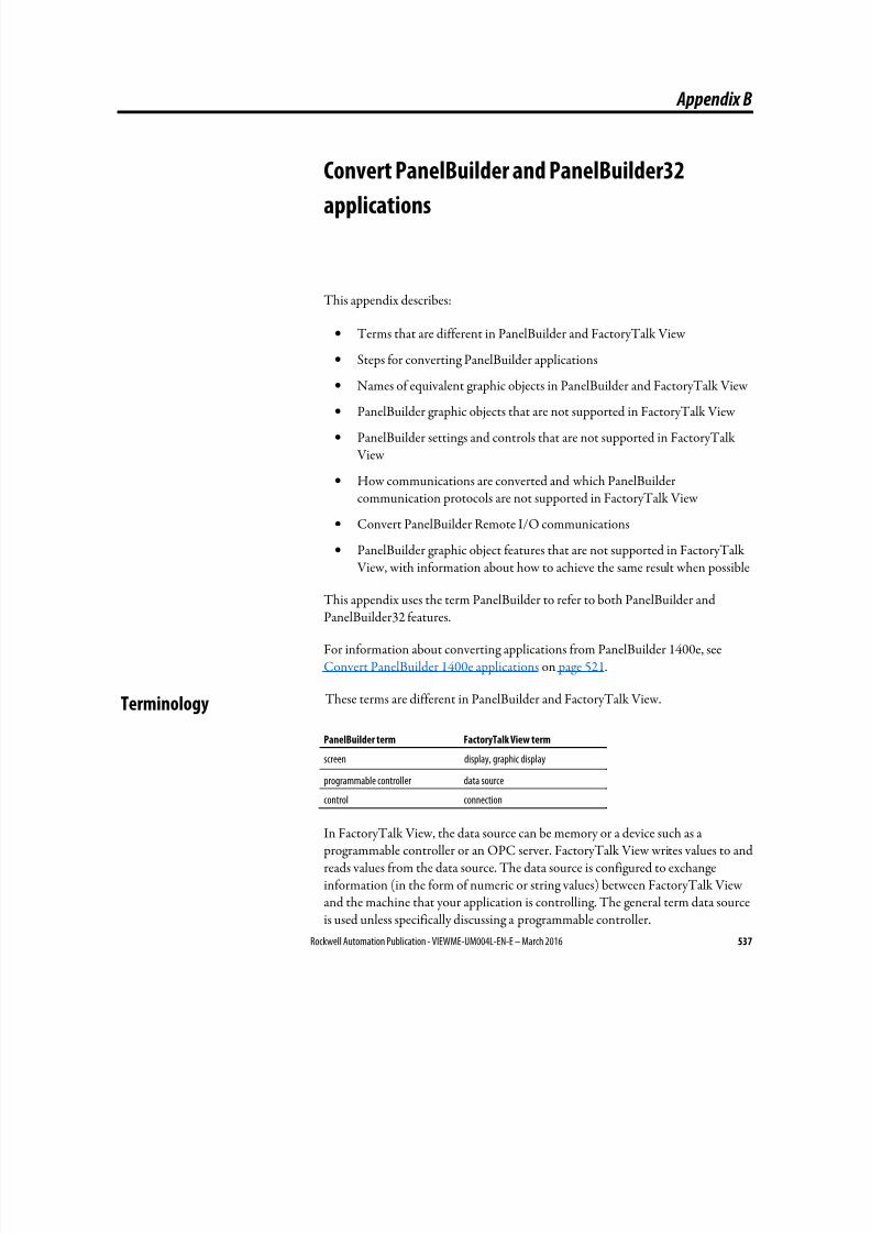
8/17/2019 FactoryTalk® View Machine Edition User's Guide
http://slidepdf.com/reader/full/factorytalk-view-machine-edition-users-guide 537/587
Rockwell Automation Publication - VIEWME-UM004L-EN-E – March 2016 537
Appendix B
Convert PanelBuilder and PanelBuilder32
applications
This appendix describes:
• Terms that are different in PanelBuilder and FactoryTalk View
• Steps for converting PanelBuilder applications
•
Names of equivalent graphic objects in PanelBuilder and FactoryTalk View
• PanelBuilder graphic objects that are not supported in FactoryTalk View
• PanelBuilder settings and controls that are not supported in FactoryTalk View
• How communications are converted and which PanelBuildercommunication protocols are not supported in FactoryTalk View
• Convert PanelBuilder Remote I/O communications
• PanelBuilder graphic object features that are not supported in FactoryTalk
View, with information about how to achieve the same result when possible
This appendix uses the term PanelBuilder to refer to both PanelBuilder andPanelBuilder32 features.
For information about converting applications from PanelBuilder 1400e, seeConvert PanelBuilder 1400e applications on page 521.
These terms are different in PanelBuilder and FactoryTalk View.
PanelBuilder term FactoryTalk View term
screen display, graphic display
programmable controller data source
control connection
In FactoryTalk View, the data source can be memory or a device such as a programmable controller or an OPC server. FactoryTalk View writes values to andreads values from the data source. The data source is configured to exchangeinformation (in the form of numeric or string values) between FactoryTalk Viewand the machine that your application is controlling. The general term data sourceis used unless specifically discussing a programmable controller.
Terminology
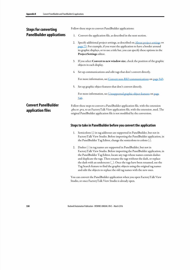
8/17/2019 FactoryTalk® View Machine Edition User's Guide
http://slidepdf.com/reader/full/factorytalk-view-machine-edition-users-guide 538/587
Appendix B Convert PanelBuilder and PanelBuilder32 applications
538 Rockwell Automation Publication - VIEWME-UM004L-EN-E – March 2016
Follow these steps to convert PanelBuilder applications:
1. Convert the application file, as described in the next section.
2.
Specify additional project settings, as described on About project settings on page 73. For example, if you want the application to have a border aroundits graphic displays, or to use a title bar, you can specify these options in theProject Settings editor.
3. If you select Convert to new window size, check the position of the graphicobjects in each display.
4. Set up communications and edit tags that don’t convert directly.
For more information, see Convert non-RIO communications on page 543.
5. Set up graphic object features that don’t convert directly.
For more information, see Unsupported graphic object features on page
546.
Follow these steps to convert a PanelBuilder application file, with the extension.pba or .pva, to an FactoryTalk View application file, with the extension .med. Theoriginal PanelBuilder application file is not modified by the conversion.
Steps to take in PanelBuilder before you convert the application
1.
Semicolons (;) in tag addresses are supported in PanelBuilder, but not inFactoryTalk View Studio. Before importing the PanelBuilder application, inthe PanelBuilder Tag Editor, change the semicolons to colons (:).
2. Dashes (-) in tag names are supported in PanelBuilder, but not inFactoryTalk View Studio. Before importing the PanelBuilder application, inthe PanelBuilder Tag Editor, locate any tags whose names contain dashesand duplicate the tags. Then rename the tags without the dash, or replacethe dash with an underscore (_). Once the tags have been renamed, use the
Tag Search feature to find the graphic objects using the original tag namesand edit the objects to replace the old tag names with the new ones.
You can convert the PanelBuilder application when you open FactoryTalk ViewStudio, or once FactoryTalk View Studio is already open.
Steps for converting
PanelBuilder applications
Convert PanelBuilder
application files
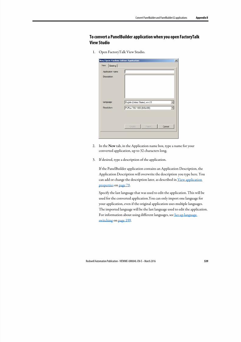
8/17/2019 FactoryTalk® View Machine Edition User's Guide
http://slidepdf.com/reader/full/factorytalk-view-machine-edition-users-guide 539/587
Convert PanelBuilder and PanelBuilder32 applications Appendix B
Rockwell Automation Publication - VIEWME-UM004L-EN-E – March 2016 539
To convert a PanelBuilder application when you open FactoryTalk
View Studio
1.
Open FactoryTalk View Studio.
2. In the New tab, in the Application name box, type a name for yourconverted application, up to 32 characters long.
3.
If desired, type a description of the application.
If the PanelBuilder application contains an Application Description, the
Application Description will overwrite the description you type here. You
can add or change the description later, as described in View application
properties on page 79.
Specify the last language that was used to edit the application. This will be
used for the converted application.You can only import one language for
your application, even if the original application uses multiple languages.
The imported language will be the last language used to edit the application.
For information about using different languages, see Set up language
switching on page 199.
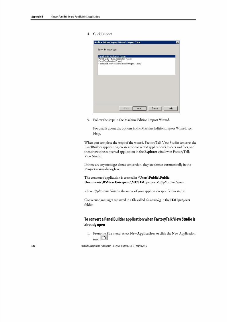
8/17/2019 FactoryTalk® View Machine Edition User's Guide
http://slidepdf.com/reader/full/factorytalk-view-machine-edition-users-guide 540/587
Appendix B Convert PanelBuilder and PanelBuilder32 applications
540 Rockwell Automation Publication - VIEWME-UM004L-EN-E – March 2016
4. Click Import.
5. Follow the steps in the Machine Edition Import Wizard.
For details about the options in the Machine Edition Import Wizard, see
Help.
When you complete the steps of the wizard, FactoryTalk View Studio converts thePanelBuilder application, creates the converted application’s folders and files, andthen shows the converted application in the Explorer window in FactoryTalk View Studio.
If there are any messages about conversion, they are shown automatically in theProject Status dialog box.
The converted application is created in \Users\Public\Public
Documents\RSView Enterprise\ME\HMI projects\ Application Name
where Application Name is the name of your application specified in step 2.
Conversion messages are saved in a file called Convert.log in the HMI projects folder.
To convert a PanelBuilder application when FactoryTalk View Studio is
already open
1. From the File menu, select New Application, or click the New Application
tool .
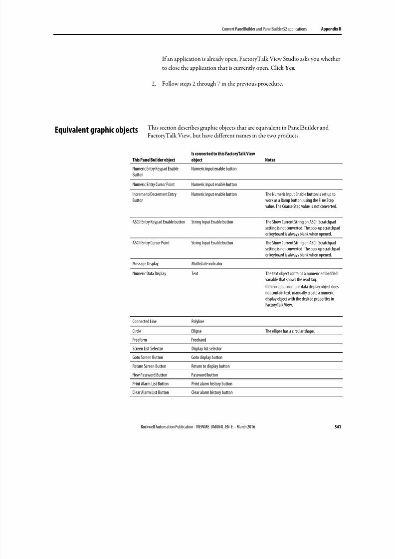
8/17/2019 FactoryTalk® View Machine Edition User's Guide
http://slidepdf.com/reader/full/factorytalk-view-machine-edition-users-guide 541/587
Convert PanelBuilder and PanelBuilder32 applications Appendix B
Rockwell Automation Publication - VIEWME-UM004L-EN-E – March 2016 541
If an application is already open, FactoryTalk View Studio asks you whether
to close the application that is currently open. Click Yes.
2.
Follow steps 2 through 7 in the previous procedure.
This section describes graphic objects that are equivalent in PanelBuilder andFactoryTalk View, but have different names in the two products.
This PanelBuilder object
Is converted to this FactoryTalk View
object Notes
Numeric Entry Keypad Enable
Button
Numeric input enable button
Numeric Entry Cursor Point Numeric input enable button
Increment/Decrement EntryButton
Numeric input enable button The Numeric Input Enable button is set up towork as a Ramp button, using the Fi ne Stepvalue. The Coarse Step value is not converted.
ASCII Entry Keypad Enable button String Input Enable button The Show Current String on ASCII Scratchpadsetting is not converted. The pop-up scratchpador keyboard is always blank when opened.
ASCII Entry Cursor Point String Input Enable button The Show Current String on ASCII Scratchpadsetting is not converted. The pop-up scratchpador keyboard is always blank when opened.
Message Display Multistate indicator
Numeric Data Display Text The text object contains a numeric embeddedvariable that shows the read tag.
If the original numeric data display object doesnot contain text, manually create a numericdisplay object with the desired properties inFactoryTalk View.
Connected Line Polyline
Circle Ellipse The ellipse has a circular shape.
Freeform Freehand
Screen List Selector Display list selector
Goto Screen Button Goto display button
Return Screen Button Return to display button
New Password Button Password button
Print Alarm List Button Print alarm history button
Clear Alarm List Button Clear alarm history button
Equivalent graphic objects
8/17/2019 FactoryTalk® View Machine Edition User's Guide
http://slidepdf.com/reader/full/factorytalk-view-machine-edition-users-guide 542/587
Appendix B Convert PanelBuilder and PanelBuilder32 applications
542 Rockwell Automation Publication - VIEWME-UM004L-EN-E – March 2016
These PanelBuilder objects are not supported in FactoryTalk View:
• Print Only Object
•
Circular Scale
• Scrolling Text
• Print Alarm Button
• Horn Silence Button
• Lamp/Horn Test Button
• Select Operator Button
• Enable/Disable Security Button
• Verify Password Button. The FactoryTalk View Password button opens adialog box that allows the user to type and verify a new password.
This section describes PanelBuilder settings and controls that are not used inFactoryTalk View.
Settings and controls for alarms
FactoryTalk View does not use these PanelBuilder features and settings to managealarms:
•
Ack setting for alarm messages - in FactoryTalk View, all alarms can beacknowledged
• Bit alarm acknowledgement
FactoryTalk View does not use these PanelBuilder controls to manage alarms:
• Remote Ack All Handshake Tag
• Remote Clear All Alarm Tag
• Remote Clear All Alarm Handshake Tag
Invalid characters in screen names and tag names
Characters in PanelBuilder screen names and tag names that are not supported inFactoryTalk View are replaced with the underscore character.
Unsupported graphic
objects
Unsupported settings and
controls
8/17/2019 FactoryTalk® View Machine Edition User's Guide
http://slidepdf.com/reader/full/factorytalk-view-machine-edition-users-guide 543/587
Convert PanelBuilder and PanelBuilder32 applications Appendix B
Rockwell Automation Publication - VIEWME-UM004L-EN-E – March 2016 543
Time and date
PanelBuilder time and date formats are not converted. For details about
FactoryTalk View time and date formats, see Time, date, and number formats forgraphic objects on page 415.
External fonts
PanelBuilder external fonts are not converted. When you convert your application you can specify the font to use instead. For details, see Help for the MachineEdition Import Wizard.
Screen security settings
PanelBuilder screen security settings are not converted, because FactoryTalk Viewuses a different method to assign security to graphic displays. For informationabout setting up security in FactoryTalk View, see Set up security on page 175.
Power-up options
These PanelBuilder power-up options are not imported into FactoryTalk View:
•
Write Last Terminal State to Controller• Display Last User Screen
• Use Terminal Presets
This section describes how communications that do not use Remote I/O (RIO)are converted.
FactoryTalk View does not use nodes for communications. Nodes are converted toRSLinx topics. Topics are then converted into device shortcuts, to run withRSLinx Enterprise. You must have both RSLinx Classic and RSLinx Enterpriseinstalled to make this two-step conversion.
Tags are converted to HMI device tags and RSLinx aliases. The Unsolicited_Msgsnode is not converted.
If you import an application multiple times, delete the device shortcuts in RSLinxEnterprise before re-importing. Otherwise, multiple unused device shortcuts willbe created in RSLinx Enterprise.
For more information about setting up communications, see Set upcommunications on page 81.
Convert non-RIO
communications
8/17/2019 FactoryTalk® View Machine Edition User's Guide
http://slidepdf.com/reader/full/factorytalk-view-machine-edition-users-guide 544/587
Appendix B Convert PanelBuilder and PanelBuilder32 applications
544 Rockwell Automation Publication - VIEWME-UM004L-EN-E – March 2016
For information about converting RIO communications, see Convert RIOcommunications on page 529.
Tags for unsupported communication protocols
Some communication protocols are not supported in FactoryTalk View. Forexample, DH+ communications that use the AutoMax node type are notsupported. FactoryTalk View does not support CIP and Assembly Objectaddressing (used in PanelBuilder32 Ethernet communications).
Tags that use unsupported communication protocols are converted to HMImemory tags. Once you have set up communications for your convertedapplication, change the memory tags to device tags that point to the correctaddresses. All other imported tags are converted to HMI device tags.
For information about editing HMI tags, see Use HMI tags on page 99. For moreinformation about which communication protocols are not supported, see Helpor see the Rockwell Automation Knowledgebase.
Bit array tags
You can monitor bit arrays for alarm conditions in FactoryTalk View, but youcan’t assign bit arrays to most graphic objects or write to bit arrays. (The onlyexception is the piloted control list selector object. For this object, you can assign a
bit array tag to the Visible States connection.)
All bit array tags in your PanelBuilder application are converted to HMI memorytags.
For information about monitoring bit arrays for alarm conditions, see Set upalarms on page 119. For information about editing HMI tags, see Use HMI tags on page 99. For information about the piloted control list selector, see Help.
Remote I/O (RIO) communications are not supported for applications that willrun on personal computers. You can use RIO communications on the PanelView
Plus and PanelView Plus CE runtime platforms.
Supported PanelBuilder tags are converted to HMI device tags and RSLinx aliases.For information about unsupported PanelBuilder tags, see below.
To convert an RIO application from PanelBuilder to FactoryTalk View
1. Convert the application, as described on Convert PanelBuilder applicationfiles on page 538.
Convert RIO
communications
8/17/2019 FactoryTalk® View Machine Edition User's Guide
http://slidepdf.com/reader/full/factorytalk-view-machine-edition-users-guide 545/587
Convert PanelBuilder and PanelBuilder32 applications Appendix B
Rockwell Automation Publication - VIEWME-UM004L-EN-E – March 2016 545
2. Open the RSLinx Enterprise data server, and then double-clickCommunication Setup.
3.
In the Communication Setup editor, add an RIO driver.
• For PanelView Plus 400 and 600 terminals, use the 2711P-RN1 driver.
• For all other PanelView Plus or PanelView Plus CE terminals, use the2711P-RN6 driver.
For information about adding drivers in RSLinx, see RSLinx Help.
4.
Expand the RIO tree, right-click RIO Data, and then click Configure RIO.
5.
In the RIO Configuration dialog box, right-click RIO, and then clickImport.
6. Browse to the location of the RIO configuration file.
The file is saved in the root of the application’s directory.
7.
In the Communications Setup editor, create a device shortcut that pointsto the RIO data device.
For information about creating a device shortcut, see RSLinx Help.
8. Apply the shortcut to the RIO driver.
9.
Correct any invalid RIO configurations. Invalid RIO configurations arehighlighted with red "x" icons.
Note: If red "x" icons appear after you im port the RIO .xml file, you can fix block tags in theCommunication Setup editor in FactoryTalk View. The length of block tags must be thesame for Read and Write pairs sharing the same rack, group, and slot.
10. Save the converted RIO application.
A PanelBuilder RIO tag will be converted to an HMI memory tag and an error will be logged to the conversion log file if the RIO tag:
• Has a blank address.
• Has a data type of Bit Array and its address does not have an array size of 1,8, 16, or 32.
• Has a data type of Bit Array, and its array size is 16 or 32, but its addressdoes not have a bit offset of 0.
• Has a data type of Bit or BOOL, and its address does not contain the bitdelimiter character "/".
Unsupported PanelBuilder
RIO tags
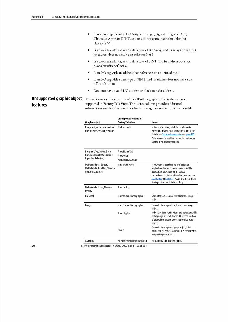
8/17/2019 FactoryTalk® View Machine Edition User's Guide
http://slidepdf.com/reader/full/factorytalk-view-machine-edition-users-guide 546/587
Appendix B Convert PanelBuilder and PanelBuilder32 applications
546 Rockwell Automation Publication - VIEWME-UM004L-EN-E – March 2016
• Has a data type of 4-BCD, Unsigned Integer, Signed Integer or INT,Character Array, or DINT, and its address contains the bit delimitercharacter "/".
•
Is a block transfer tag with a data type of Bit Array, and its array size is 8, butits address does not have a bit offset of 0 or 8.
• Is a block transfer tag with a data type of SINT, and its address does nothave a bit offset of 0 or 8.
• Is an I/O tag with an address that references an undefined rack.
• Is an I/O tag with a data type of SINT, and its address does not have a bitoffset of 0 or 10.
• Does not have a valid I/O address or block transfer address.
This section describes features of PanelBuilder graphic objects that are notsupported in FactoryTalk View. The Notes column provides additionalinformation and describes methods for achieving the same result when possible.
Graphic object
Unsupported feature in
FactoryTalk View Notes
Image text, arc, ellipse, freehand,line, polyline, rectangle, wedge
Blink property In FactoryTalk View, all of the listed objectsexcept images use color animation to blink. Fordetails, see Set up color animation on page 425.
Color images do not blink. Monochrome imagesuse the Blink property to blink.
Increment/Decrement EntryButton (Converted to NumericInput Enable button)
Allow Home/End
Allow Wrap
Ramp by coarse steps
Maintained push Button,Multistate Push Button, StandardControl List Selector
Initial state values If you want to set these objects’ states onapplication startup, create a macro to set theappropriate tag values for the objects’connections. For information about macros, seeUse macros on page 517. Assign the macro in theStartup editor. For details, see Help.
Multistate Indicator, MessageDisplay
Print Setting
Bar Graph Inner text and inner graphic Converted to a separate text object and image
object.
Gauge Inner text and inner graphic
Scale clipping
Needle
Converted to a separate text object and im ageobject.
If the scale does not fit within the height or widthof the gauge, it is not clipped. Check the positionof the scale to ensure it does not overlap otherobjects.
Converted to a separate gauge object; if thegauge had 2 needles, each needle is converted toa separate gauge object.
Alarm List No Acknowledgement Required All alarms can be acknowledged.
Unsupported graphic objectfeatures

8/17/2019 FactoryTalk® View Machine Edition User's Guide
http://slidepdf.com/reader/full/factorytalk-view-machine-edition-users-guide 547/587
Convert PanelBuilder and PanelBuilder32 applications Appendix B
Rockwell Automation Publication - VIEWME-UM004L-EN-E – March 2016 547
Graphic object
Unsupported feature in
FactoryTalk View Notes
All objects Image placement FactoryTalk View supports one, three or ninepositions for images, depending on the type ofobject. On conversion, images are positionedusing the closest match. Therefore some i magesmight be clipped to fit the object.
All objects Turn Object View On property If this property is set to False, the convertedobject has a transparent background, no border,no caption, and no image.
All objects Blinking inner graphics If the inner graphic uses a color image, it will notblink. Use a monochrome image if you want theinner graphic to blink.

8/17/2019 FactoryTalk® View Machine Edition User's Guide
http://slidepdf.com/reader/full/factorytalk-view-machine-edition-users-guide 548/587
Appendix B Convert PanelBuilder and PanelBuilder32 applications
548 Rockwell Automation Publication - VIEWME-UM004L-EN-E – March 2016
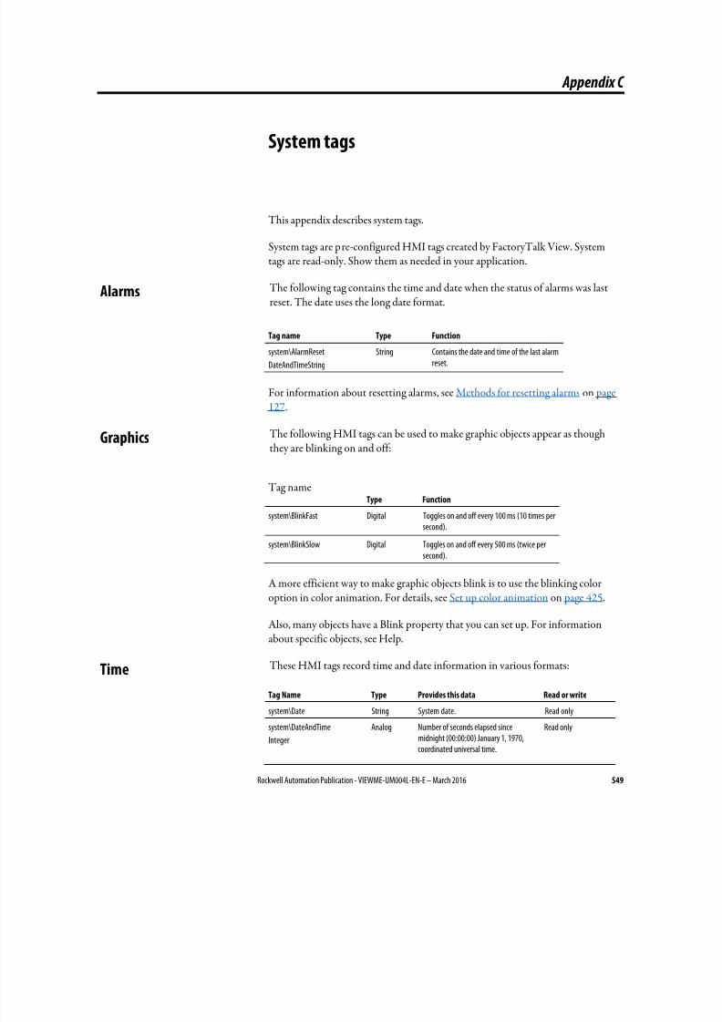
8/17/2019 FactoryTalk® View Machine Edition User's Guide
http://slidepdf.com/reader/full/factorytalk-view-machine-edition-users-guide 549/587
Rockwell Automation Publication - VIEWME-UM004L-EN-E – March 2016 549
Appendix C
System tags
This appendix describes system tags.
System tags are pre-configured HMI tags created by FactoryTalk View. Systemtags are read-only. Show them as needed in your application.
The following tag contains the time and date when the status of alarms was lastreset. The date uses the long date format.
Tag name Type Function
system\AlarmReset
DateAndTimeString
String Contains the date and time of the last alarmreset.
For information about resetting alarms, see Methods for resetting alarms on page127.
The following HMI tags can be used to make graphic objects appear as thoughthey are blinking on and off:
Tag nameType Function
system\BlinkFast Digital Toggles on and off every 100 ms (10 times persecond).
system\BlinkSlow Digital Toggles on and off every 500 ms (twice persecond).
A more efficient way to make graphic objects blink is to use the blinking coloroption in color animation. For details, see Set up color animation on page 425.
Also, many objects have a Blink property that you can set up. For information
about specific objects, see Help.
These HMI tags record time and date information in various formats:
Tag Name Type Provides this data Read or write
system\Date String System date. Read only
system\DateAndTime
Integer
Analog Number of seconds elapsed sincemidnight (00:00:00) January 1, 1970,coordinated universal time.
Read only
Alarms
Graphics
Time
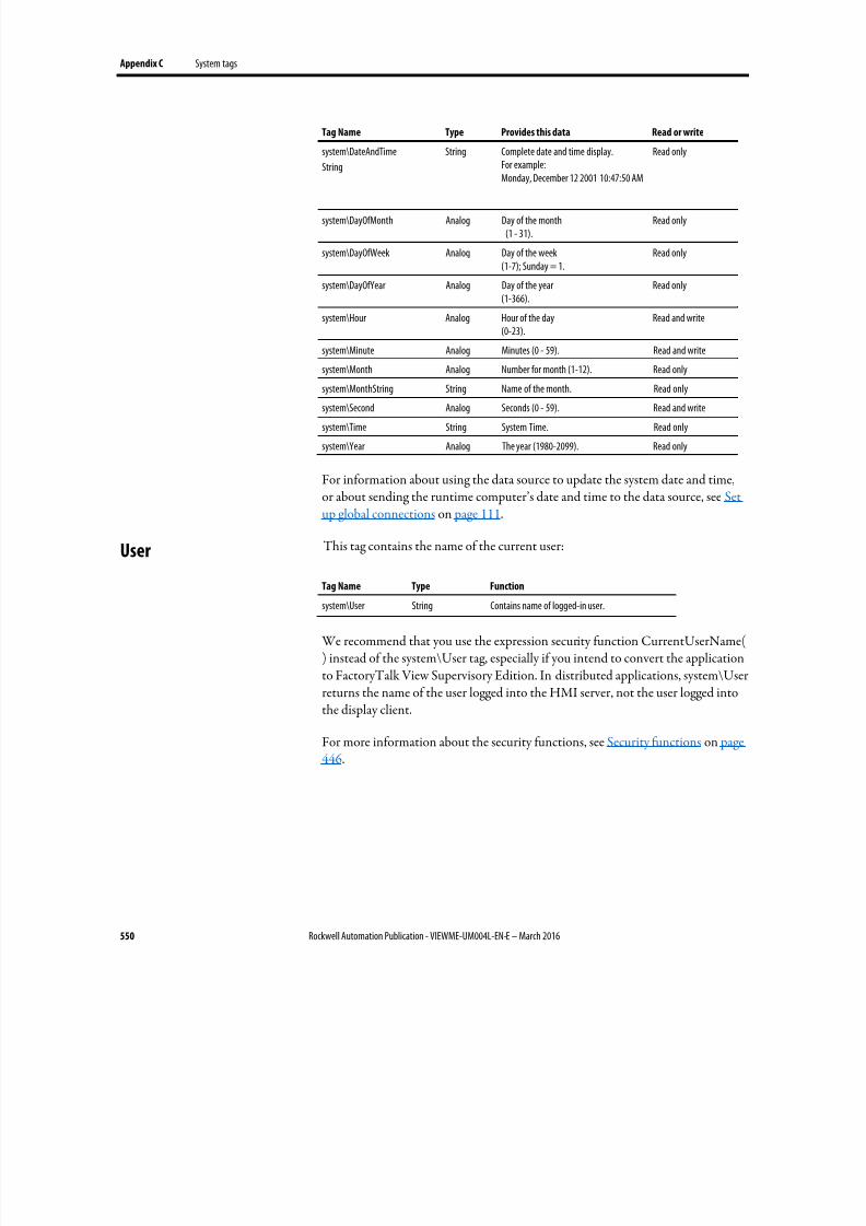
8/17/2019 FactoryTalk® View Machine Edition User's Guide
http://slidepdf.com/reader/full/factorytalk-view-machine-edition-users-guide 550/587
Appendix C System tags
550 Rockwell Automation Publication - VIEWME-UM004L-EN-E – March 2016
Tag Name Type Provides this data Read or write
system\DateAndTime
String
String Complete date and time display.For example:Monday, December 12 2001 10:47:50 AM
Read only
system\DayOfMonth Analog Day of the month(1 - 31).
Read only
system\DayOfWeek Analog Day of the week(1-7); Sunday = 1.
Read only
system\DayOfYear Analog Day of the year(1-366).
Read only
system\Hour Analog Hour of the day(0-23).
Read and write
system\Minute Analog Minutes (0 - 59). Read and write
system\Month Analog Number for month (1-12). Read only
system\MonthString String Name of the month. Read only
system\Second Analog Seconds (0 - 59). Read and write
system\Time String System Time. Read only
system\Year Analog The year (1980-2099). Read only
For information about using the data source to update the system date and time,or about sending the runtime computer’s date and time to the data source, see Setup global connections on page 111.
This tag contains the name of the current user:
Tag Name Type Function
system\User String Contains name of logged-in user.
We recommend that you use the expression security function CurrentUserName() instead of the system\User tag, especially if you intend to convert the applicationto FactoryTalk View Supervisory Edition. In distributed applications, system\Userreturns the name of the user logged into the HMI server, not the user logged intothe display client.
For more information about the security functions, see Security functions on page
446.
User
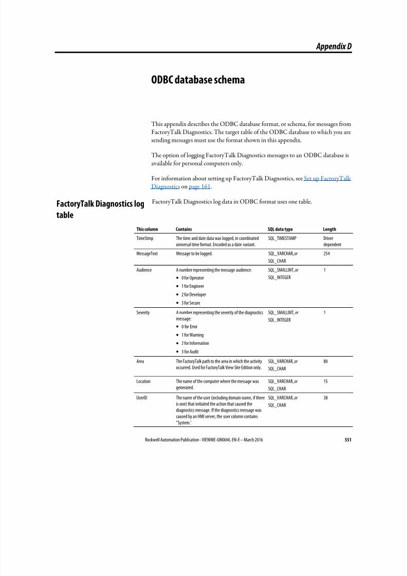
8/17/2019 FactoryTalk® View Machine Edition User's Guide
http://slidepdf.com/reader/full/factorytalk-view-machine-edition-users-guide 551/587
Rockwell Automation Publication - VIEWME-UM004L-EN-E – March 2016 551
Appendix D
ODBC database schema
This appendix describes the ODBC database format, or schema, for messages fromFactoryTalk Diagnostics. The target table of the ODBC database to which you aresending messages must use the format shown in this appendix.
The option of logging FactoryTalk Diagnostics messages to an ODBC database isavailable for personal computers only.
For information about setting up FactoryTalk Diagnostics, see Set up FactoryTalkDiagnostics on page 161.
FactoryTalk Diagnostics log data in ODBC format uses one table.
This column Contains SQL data type Length
TimeStmp The time and date data was logged, in coordinateduniversal time format. Encoded as a date variant.
SQL_TIMESTAMP Driverdependent
MessageText Message to be logged. SQL_VARCHAR, or
SQL_CHAR
254
Audience A number representing the message audience:
• 0 for Operator
• 1 for Engineer
• 2 for Developer
• 3 for Secure
SQL_SMALLINT, or
SQL_INTEGER
1
Severity A number representing the severity of the diagnosticsmessage:
• 0 for Error
• 1 for Warning
• 2 for Information
• 3 for Audit
SQL_SMALLINT, or
SQL_INTEGER
1
Area The FactoryTalk path to the area in which the activityoccurred. Used for FactoryTalk View Site Edition only.
SQL_VARCHAR, or
SQL_CHAR
80
Location The name of the computer where the message wasgenerated.
SQL_VARCHAR, or
SQL_CHAR
15
UserID The name of the user (including domain name, if thereis one) that initiated the action that caused thediagnostics message. If the diagnostics message wascaused by an HMI server, the user column contains"System."
SQL_VARCHAR, or
SQL_CHAR
38
FactoryTalk Diagnostics log
table

8/17/2019 FactoryTalk® View Machine Edition User's Guide
http://slidepdf.com/reader/full/factorytalk-view-machine-edition-users-guide 552/587
Appendix D ODBC database schema
552 Rockwell Automation Publication - VIEWME-UM004L-EN-E – March 2016
This column Contains SQL data type Length
UserFullName The full name of the user that was logged in when theactivity occurred.
SQL_VARCHAR, or
SQL_CHAR
255
Provider The name of the product that generated the message. SQL_VARCHAR, or SQL_CHAR
20

8/17/2019 FactoryTalk® View Machine Edition User's Guide
http://slidepdf.com/reader/full/factorytalk-view-machine-edition-users-guide 553/587
Rockwell Automation Publication - VIEWME-UM004L-EN-E – March 2016 553
Appendix E
Import and export alarm XML files
This appendix describes:
• Create alarm XML files
• Export, editing, and importing XML files
• The alarm XML file structure
XML is the Extensible Markup Language used to create documents withstructured text information. It has a standardized format and structure. You canuse XML to edit the elements and attributes needed to create an alarm setup file orto modify graphic displays. For information about working with graphics XMLfiles, see Import and export graphics XML files on page 565.
Sometimes editing your alarm setup in an XML file is quicker than working inFactoryTalk View. For example, if you have a list of 100 tags to monitor foralarms, with multiple messages for each tag, you might prefer to enter all theinformation in a text editor, and then import the alarm setup information intoFactoryTalk View.
Another example of using XML files is to export the alarm setup information youdevelop in one application, import the setup information to another FactoryTalk View application, and then modify the alarm setup as needed. Or, you couldmodify the information in the XML file before importing it.
For more information about XML, see the World Wide Web Consortium’s web page about XML at http://www.w3.org/XML/.
The quickest way to create an XML file for your application’s alarm setup is toexport the data from FactoryTalk View. You can then open the XML file inNotepad, make your changes, and import the file back into FactoryTalk View.
Tip: The strings for the application’s current language are exported to the XML file. To exportstrings for another language, reopen the application in the new language and repeat theXML export.
About XML
Create alarm XML files by
exporting
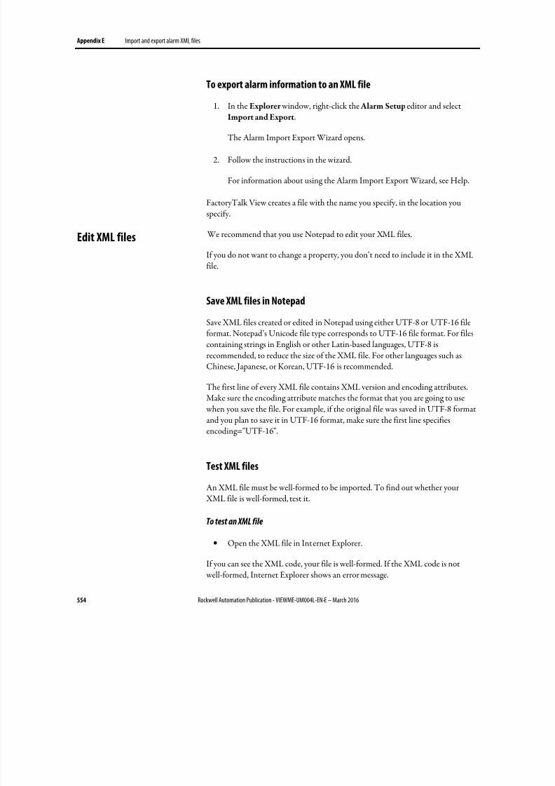
8/17/2019 FactoryTalk® View Machine Edition User's Guide
http://slidepdf.com/reader/full/factorytalk-view-machine-edition-users-guide 554/587
Appendix E Import and export alarm XML files
554 Rockwell Automation Publication - VIEWME-UM004L-EN-E – March 2016
To export alarm information to an XML file
1. In the Explorer window, right-click the Alarm Setup editor and select
Import and Export.
The Alarm Import Export Wizard opens.
2. Follow the instructions in the wizard.
For information about using the Alarm Import Export Wizard, see Help.
FactoryTalk View creates a file with the name you specify, in the location youspecify.
We recommend that you use Notepad to edit your XML files.
If you do not want to change a property, you don’t need to include it in the XMLfile.
Save XML files in Notepad
Save XML files created or edited in Notepad using either UTF-8 or UTF-16 fileformat. Notepad’s Unicode file type corresponds to UTF-16 file format. For filescontaining strings in English or other Latin-based languages, UTF-8 isrecommended, to reduce the size of the XML file. For other languages such as
Chinese, Japanese, or Korean, UTF-16 is recommended.
The first line of every XML file contains XML version and encoding attributes.Make sure the encoding attribute matches the format that you are going to use when you save the file. For example, if the original file was saved in UTF-8 formatand you plan to save it in UTF-16 format, make sure the first line specifiesencoding="UTF-16".
Test XML files
An XML file must be well-formed to be imported. To find out whether your XML file is well-formed, test it.
To test an XML file
• Open the XML file in Internet Explorer.
If you can see the XML code, your file is well-formed. If the XML code is not well-formed, Internet Explorer shows an error message.
Edit XML files
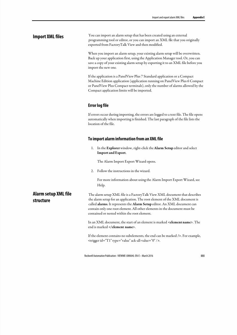
8/17/2019 FactoryTalk® View Machine Edition User's Guide
http://slidepdf.com/reader/full/factorytalk-view-machine-edition-users-guide 555/587
Import and export alarm XML files Appendix E
Rockwell Automation Publication - VIEWME-UM004L-EN-E – March 2016 555
You can import an alarm setup that has been created using an external programming tool or editor, or you can import an XML file that you originallyexported from FactoryTalk View and then modified.
When you import an alarm setup, your existing alarm setup will be overwritten.Back up your application first, using the Application Manager tool. Or, you cansave a copy of your existing alarm setup by exporting it to an XML file before youimport the new one.
If the application is a PanelView Plus 7 Standard application or a CompactMachine Edition application (application running on PanelView Plus 6 Compactor PanelView Plus Compact terminals), only the number of alarms allowed by theCompact application limits will be imported.
Error log file
If errors occur during importing, the errors are logged to a text file. The file opensautomatically when importing is finished. The last paragraph of the file lists thelocation of the file.
To import alarm information from an XML file
1. In the Explorer window, right-click the Alarm Setup editor and selectImport and Export.
The Alarm Import Export Wizard opens.
2. Follow the instructions in the wizard.
For more information about using the Alarm Import Export Wizard, see
Help.
The alarm setup XML file is a FactoryTalk View XML document that describesthe alarm setup for an application. The root element of the XML document iscalled alarms. It represents the Alarm Setup editor. An XML document can
contain only one root element. All other elements in the document must becontained or nested within the root element.
In an XML document, the start of an element is marked <element name>. Theend is marked </element name>.
If the element contains no subelements, the end can be marked />. For example,<trigger id="T1" type="value" ack-all-value="0" />.
Import XML files
Alarm setup XML file
structure
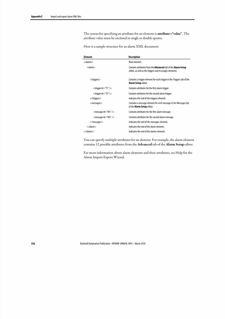
8/17/2019 FactoryTalk® View Machine Edition User's Guide
http://slidepdf.com/reader/full/factorytalk-view-machine-edition-users-guide 556/587
Appendix E Import and export alarm XML files
556 Rockwell Automation Publication - VIEWME-UM004L-EN-E – March 2016
The syntax for specifying an attribute for an element is attribute="value" . Theattribute value must be enclosed in single or double quotes.
Here is a sample structure for an alarm XML document:
Element Description
<alarms> Root element.
<alarm> Contains attributes from the Advanced tab of the Alarm Setup editor, as well as the triggers and m essages elements.
<triggers> Contains a trigger element for each trigger in the Triggers tab of theAlarm Setup editor.
<trigger id="T1" /> Contains attributes for the first alarm trigger.
<trigger id="T2" /> Contains attributes for the second alarm trigger.
</triggers> Indicates the end of the triggers element.<messages> Contains a message element for each message in the Messages tab
of the Alarm Setup editor.
<message id="M1" /> Contains attributes for the first alarm message.
<message id="M2" /> Contains attributes for the second alarm message.
</messages> Indicates the end of the messages element.
</alarm> Indicates the end of the alarm element.
</alarms> Indicates the end of the alarms element.
You can specify multiple attributes for an element. For example, the alarm elementcontains 12 possible attributes from the Advanced tab of the Alarm Setup editor.
For more information about alarm elements and their attributes, see Help for theAlarm Import Export Wizard.
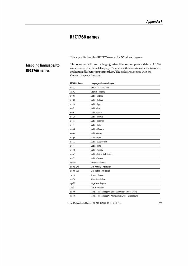
8/17/2019 FactoryTalk® View Machine Edition User's Guide
http://slidepdf.com/reader/full/factorytalk-view-machine-edition-users-guide 557/587
Rockwell Automation Publication - VIEWME-UM004L-EN-E – March 2016 557
Appendix F
RFC1766 names
This appendix describes RFC1766 names for Windows languages.
The following table lists the languages that Windows supports and the RFC1766name associated with each language. You can use the codes to name the translatedapplication files before importing them. The codes are also used with theCurrentLanguage function.
RFC1766 Name Language – Country/Region
af–ZA Afrikaans – South Africa
sq–AL Albanian – Albania
ar–DZ Arabic – Algeria
ar–BH Arabic – Bahrain
ar–EG Arabic – Egypt
ar–IQ Arabic – Iraq
ar–JO Arabic – Jordan
ar–KW Arabic – Kuwait
ar–LB Arabic – Lebanon
ar–LY Arabic – Lybia
ar–MA Arabic – Morocco
ar–OM Arabic – Oman
ar–QA Arabic – Qatar
ar–SA Arabic – Saudi Arabia
ar–SY Arabic – Syria
ar–TN Arabic – Tunisia
ar–AE Arabic – United Arab Emirates
ar–YE Arabic – Yemen
hy–AM Armenian – Armenia
az–AZ–Cyrl Azeri (Cyrillic) – Azerbaijan
az–AZ–Latn Azeri (Latin) – Azerbaijan
eu–ES Basque – Basque
be–BY Belarusian – Belarus
bg–BG Bulgarian – Bulgaria
ca–ES Catalan – Catalan
zh–HK Chinese – Hong Kong SAR (Default Sort Order – Stroke Count)
zh–HK Chinese – Hong Kong SAR (Alternate Sort Order – Stroke Count)
Mapping languages to
RFC1766 names
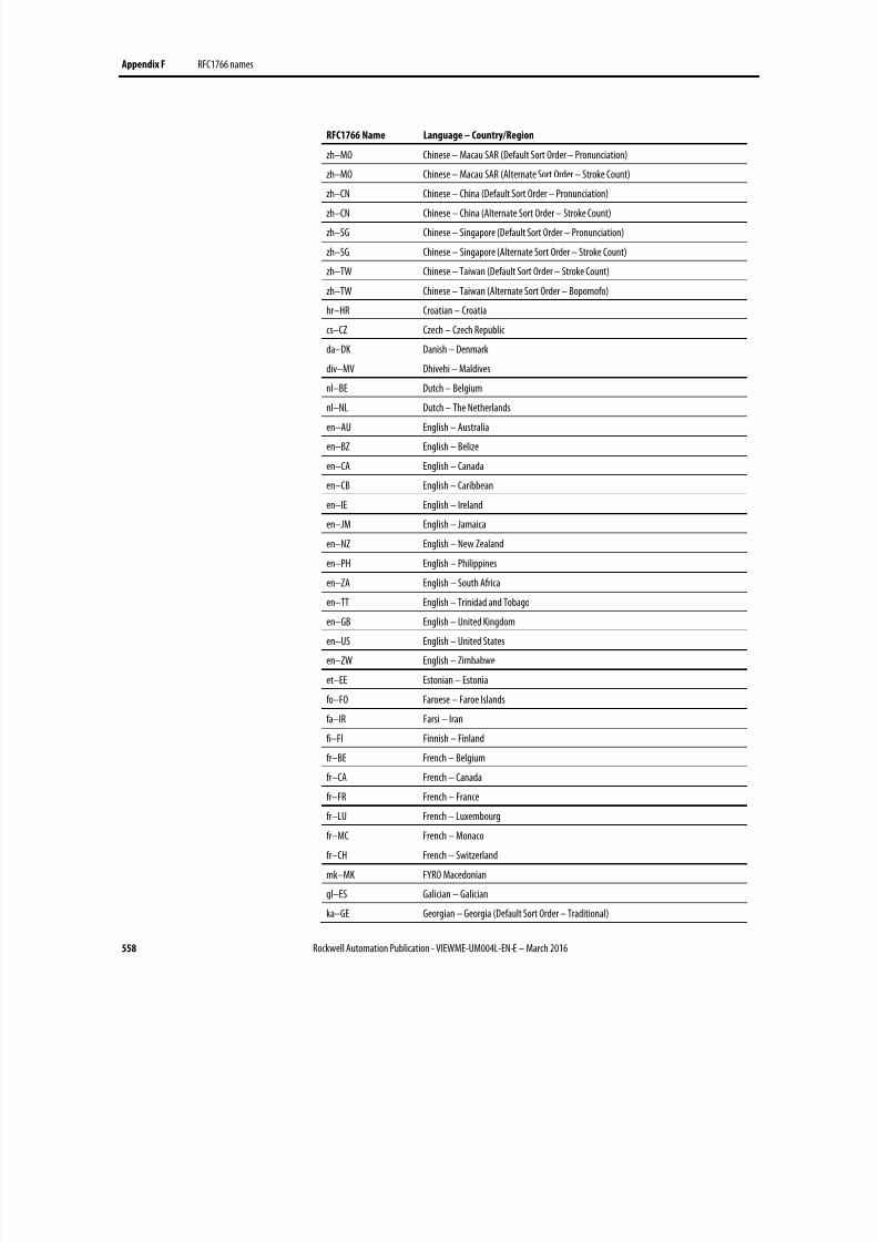
8/17/2019 FactoryTalk® View Machine Edition User's Guide
http://slidepdf.com/reader/full/factorytalk-view-machine-edition-users-guide 558/587
Appendix F RFC1766 names
558 Rockwell Automation Publication - VIEWME-UM004L-EN-E – March 2016
RFC1766 Name Language – Country/Region
zh–MO Chinese – Macau SAR (Default Sort Order – Pronunciation)
zh–MO Chinese – Macau SAR (Alternate Sort Order – Stroke Count)
zh–CN Chinese – China (Default Sort Order – Pronunciation)
zh–CN Chinese – China (Alternate Sort Order – Stroke Count)
zh–SG Chinese – Singapore (Default Sort Order – Pronunciation)
zh–SG Chinese – Singapore (Alternate Sort Order – Stroke Count)
zh–TW Chinese – Taiwan (Default Sort Order – Stroke Count)
zh–TW Chinese – Taiwan (Alternate Sort Order – Bopomofo)
hr–HR Croatian – Croatia
cs–CZ Czech – Czech Republic
da–DK Danish – Denmark
div–MV Dhivehi – Maldives
nl–BE Dutch – Belgium
nl–NL Dutch – The Netherlands
en–AU English – Australia
en–BZ English – Belize
en–CA English – Canada
en–CB English – Caribbean
en–IE English – Ireland
en–JM English – Jamaica
en–NZ English – New Zealand
en–PH English – Philippines
en–ZA English – South Africa
en–TT English – Trinidad and Tobago
en–GB English – United Kingdom
en–US English – United States
en–ZW English – Zimbabwe
et–EE Estonian – Estonia
fo–FO Faroese – Faroe Islands
fa–IR Farsi – Iran
fi–FI Finnish – Finland
fr–BE French – Belgium
fr–CA French – Canada
fr–FR French – France
fr–LU French – Luxembourg
fr–MC French – Monaco
fr–CH French – Switzerland
mk–MK FYRO Macedonian
gl–ES Galician – Galician
ka–GE Georgian – Georgia (Default Sort Order – Traditional)
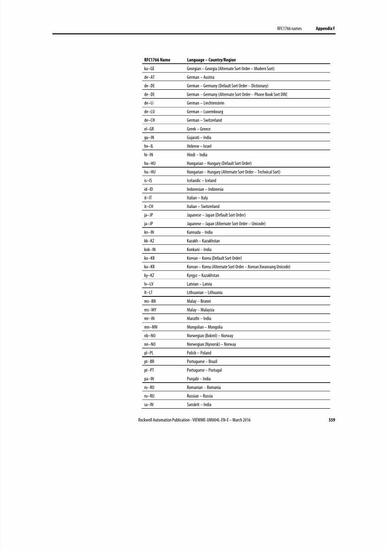
8/17/2019 FactoryTalk® View Machine Edition User's Guide
http://slidepdf.com/reader/full/factorytalk-view-machine-edition-users-guide 559/587
RFC1766 names Appendix F
Rockwell Automation Publication - VIEWME-UM004L-EN-E – March 2016 559
RFC1766 Name Language – Country/Region
ka–GE Georgian – Georgia (Alternate Sort Order – Modern Sort)
de–AT German – Austria
de–DE German – Germany (Default Sort Order – Dictionary)
de–DE German – Germany (Alternate Sort Order – Phone Book Sort DIN)
de–LI German – Liechtenstein
de–LU German – Luxembourg
de–CH German – Switzerland
el–GR Greek – Greece
gu–IN Gujarati – India
he–IL Hebrew – Israel
hi–IN Hindi – India
hu–HU Hungarian – Hungary (Default Sort Order)
hu–HU Hungarian – Hungary (Alternate Sort Order – Technical Sort)
is–IS Icelandic – Iceland
id–ID Indonesian – Indonesia
it–IT Italian – Italy
it–CH Italian – Switzerland
ja–JP Japanese – Japan (Default Sort Order)
ja–JP Japanese – Japan (Alternate Sort Order – Unicode)
kn–IN Kannada – India
kk–KZ Kazakh – Kazakhstan
kok–IN Konkani – India
ko–KR Korean – Korea (Default Sort Order)
ko–KR Korean – Korea (Alternate Sort Order – Korean Xwansung Unicode)
ky–KZ Kyrgyz – Kazakhstan
lv–LV Latvian – Latvia
lt–LT Lithuanian – Lithuania
ms–BN Malay – Brunei
ms–MY Malay – Malaysia
mr–IN Marathi – India
mn–MN Mongolian – Mongolia
nb–NO Norwegian (Bokml) – Norway
nn–NO Norwegian (Nynorsk) – Norway
pl–PL Polish – Poland
pt–BR Portuguese – Brazil
pt–PT Portuguese – Portugal
pa–IN Punjabi – India
ro–RO Romanian – Romania
ru–RU Russian – Russia
sa–IN Sanskrit – India
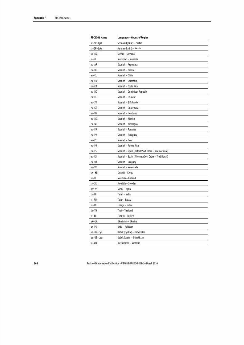
8/17/2019 FactoryTalk® View Machine Edition User's Guide
http://slidepdf.com/reader/full/factorytalk-view-machine-edition-users-guide 560/587
Appendix F RFC1766 names
560 Rockwell Automation Publication - VIEWME-UM004L-EN-E – March 2016
RFC1766 Name Language – Country/Region
sr–SP–Cyrl Serbian (Cyrillic) – Serbia
sr–SP–Latn Serbian (Latin) – Serbia
sk–SK Slovak – Slovakia
sl–SI Slovenian – Slovenia
es–AR Spanish – Argentina
es–BO Spanish – Bolivia
es–CL Spanish – Chile
es–CO Spanish – Colombia
es–CR Spanish – Costa Rica
es–DO Spanish – Dominican Republic
es–EC Spanish – Ecuador
es–SV Spanish – El Salvador
es–GT Spanish – Guatemala
es–HN Spanish – Honduras
es–MX Spanish – Mexico
es–NI Spanish – Nicaragua
es–PA Spanish – Panama
es–PY Spanish – Paraguay
es–PE Spanish – Peru
es–PR Spanish – Puerto Rico
es–ES Spanish – Spain (Default Sort Order – International)
es–ES Spanish – Spain (Alternate Sort Order – Traditional)
es–UY Spanish – Uruguay
es–VE Spanish – Venezuela
sw–KE Swahili – Kenya
sv–FI Swedish – Finland
sv–SE Swedish – Sweden
syr–SY Syriac – Syria
ta–IN Tamil – India
tt–RU Tatar – Russia
te–IN Telugu – India
th–TH Thai – Thailand
tr–TR Turkish – Turkey
uk–UA Ukrainian – Ukraine
ur–PK Urdu – Pakistan
uz–UZ–Cyrl Uzbek (Cyrillic) – Uzbekistan
uz–UZ–Latn Uzbek (Latin) – Uzbekistan
vi–VN Vietnamese – Vietnam
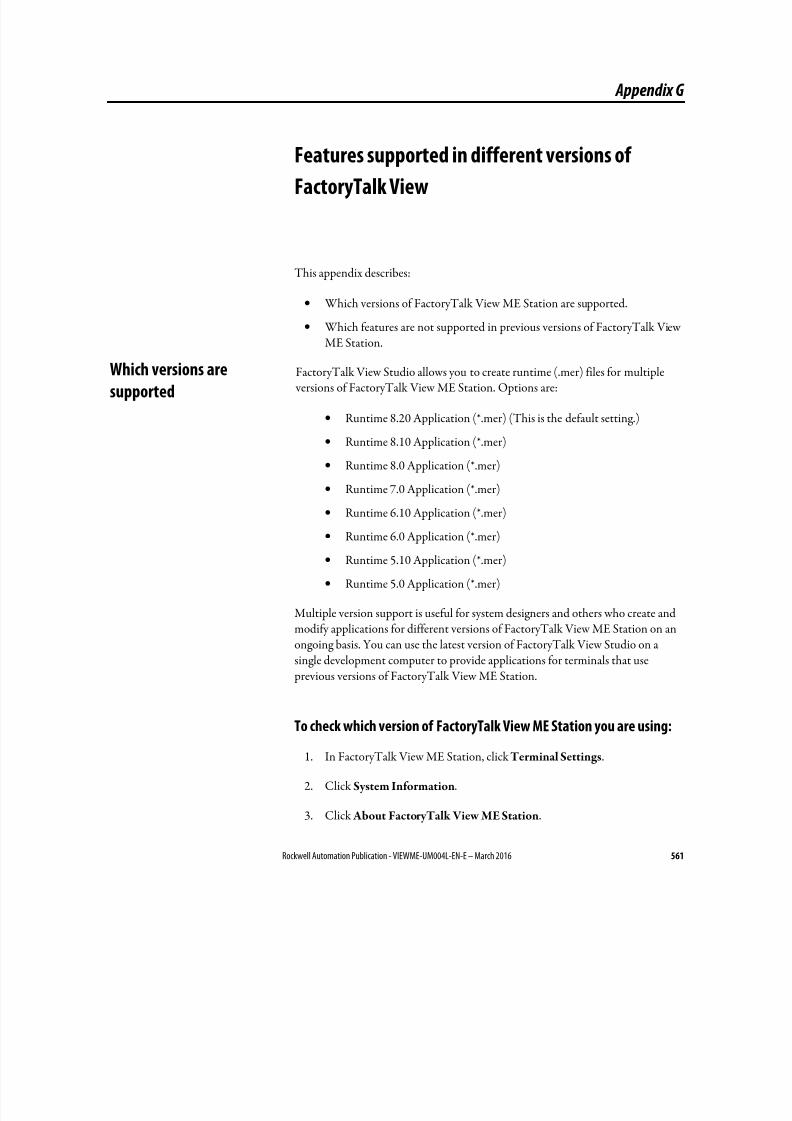
8/17/2019 FactoryTalk® View Machine Edition User's Guide
http://slidepdf.com/reader/full/factorytalk-view-machine-edition-users-guide 561/587
Rockwell Automation Publication - VIEWME-UM004L-EN-E – March 2016 561
Appendix G
Features supported in different versions of
FactoryTalk View
This appendix describes:
• Which versions of FactoryTalk View ME Station are supported.
• Which features are not supported in previous versions of FactoryTalk View
ME Station.
FactoryTalk View Studio allows you to create runtime (.mer) files for multiple versions of FactoryTalk View ME Station. Options are:
• Runtime 8.20 Application (*.mer) (This is the default setting.)
• Runtime 8.10 Application (*.mer)
• Runtime 8.0 Application (*.mer)
• Runtime 7.0 Application (*.mer)
• Runtime 6.10 Application (*.mer)
• Runtime 6.0 Application (*.mer)
• Runtime 5.10 Application (*.mer)
• Runtime 5.0 Application (*.mer)
Multiple version support is useful for system designers and others who create andmodify applications for different versions of FactoryTalk View ME Station on anongoing basis. You can use the latest version of FactoryTalk View Studio on asingle development computer to provide applications for terminals that use previous versions of FactoryTalk View ME Station.
To check which version of FactoryTalk View ME Station you are using:
1. In FactoryTalk View ME Station, click Terminal Settings.
2. Click System Information.
3. Click About FactoryTalk View ME Station.
Which versions are
supported
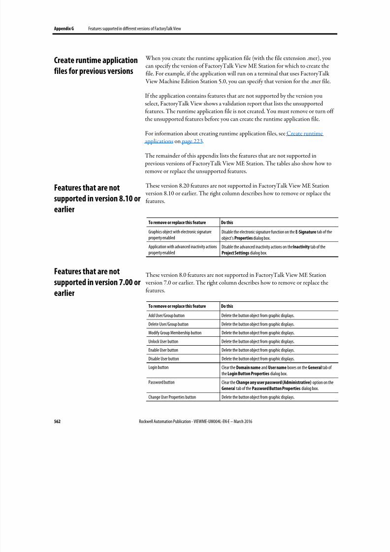
8/17/2019 FactoryTalk® View Machine Edition User's Guide
http://slidepdf.com/reader/full/factorytalk-view-machine-edition-users-guide 562/587
Appendix G Features supported in different versions of FactoryTalk View
562 Rockwell Automation Publication - VIEWME-UM004L-EN-E – March 2016
When you create the runtime application file (with the file extension .mer), youcan specify the version of FactoryTalk View ME Station for which to create thefile. For example, if the application will run on a terminal that uses FactoryTalk View Machine Edition Station 5.0, you can specify that version for the .mer file.
If the application contains features that are not supported by the version youselect, FactoryTalk View shows a validation report that lists the unsupportedfeatures. The runtime application file is not created. You must remove or turn offthe unsupported features before you can create the runtime application file.
For information about creating runtime application files, see Create runtimeapplications on page 223.
The remainder of this appendix lists the features that are not supported in previous versions of FactoryTalk View ME Station. The tables also show how to
remove or replace the unsupported features.
These version 8.20 features are not supported in FactoryTalk View ME Station version 8.10 or earlier. The right column describes how to remove or replace thefeatures.
To remove or replace this feature Do this
Graphics object with electronic signatureproperty enabled
Disable the electronic signature function on the E-Signature tab of theobject's Properties dialog box.
Application with advanced inactivity actionsproperty enabled
Disable the advanced inactivity actions on the Inactivity tab of theProject Settings dialog box.
These version 8.0 features are not supported in FactoryTalk View ME Station version 7.0 or earlier. The right column describes how to remove or replace thefeatures.
To remove or replace this feature Do this
Add User/Group button Delete the button object from graphic displays.
Delete User/Group button Delete the button object from graphic displays.
Modify Group Membership button Delete the button object from graphic displays.
Unlock User button Delete the button object from graphic displays.Enable User button Delete the button object from graphic displays.
Disable User button Delete the button object from graphic displays.
Login button Clear the Domain name and User name boxes on the General tab ofthe Login Button Properties dialog box.
Password button Clear the Change any user password (Administrative) option on theGeneral tab of the Password Button Properties dialog box.
Change User Properties button Delete the button object from graphic displays.
Create runtime application
files for previous versions
Features that are not
supported in version 8.10 or
earlier
Features that are not
supported in version 7.00 or
earlier
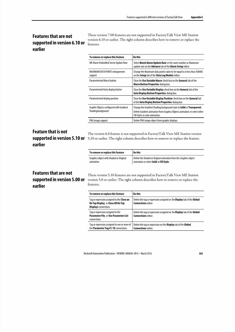
8/17/2019 FactoryTalk® View Machine Edition User's Guide
http://slidepdf.com/reader/full/factorytalk-view-machine-edition-users-guide 563/587
Features supported in different versions of FactoryTalk View Appendix G
Rockwell Automation Publication - VIEWME-UM004L-EN-E – March 2016 563
These version 7.00 features are not supported in FactoryTalk View ME Station version 6.10 or earlier. The right column describes how to remove or replace thefeatures.
To remove or replace this feature Do this
ME Alarm Embedded Server Update Rate Select Match Alarm Update Rate or the same number as Maximumupdate rate on the Advance tab of the Alarm Setup editor.
MAXIMUM DATA POINTS enlargementsupport
Change the Maximum data points value to be equal to or less than 300000on the Setup tab of the Data Log Models editor.
Parameterized Macro button Clear the Use Variable Macro check box on the General tab of theMacro Button Properties dialog box.
Parameterized Goto display button Clear the Use Variable Display check box on the General tab of theGoto Display Button Properties dialog box.
Parameterized display position Clear the Use Variable Display Position check box on the General tab
of the Goto Display Button Properties dialog box.Graphic Objects configured with GradientShading background
Change the Gradient Shading background style to Solid or Transparent.
Delete Gradient animation from Graphics Objects animation or select otherFill Styles in color animation.
PNG image support Delete PNG image object from graphic displays.
The version 6.0 feature is not supported in FactoryTalk View ME Station version5.10 or earlier. The right column describes how to remove or replace the feature.
To remove or replace this feature Do this
Graphics object with Shaded or Originalanimation
Delete the Shaded or Original animation from the Graphics objectanimation or select Solid in Fill Style.
These version 5.10 features are not supported in FactoryTalk View ME Station version 5.0 or earlier. The right column describes how to remove or replace thefeatures.
To remove or replace this feature Do this
Tag or expression assigned to the Close an
On Top Display, or Close All On Top
Displays connections
Delete the tag or expression assigned on the Display tab of the Global
Connections editor.
Tag or expression assigned to theParameter File, or Use Parameter List connections
Delete the tag or expression assigned on the Display tab of the Global
Connections editor.
Tag or expression assigned to one or more ofthe Parameter Tag #1-10 connections
Delete the tag or expression on the Display tab of the Global
Connections editor.
Features that are not
supported in version 6.10 or
earlier
Feature that is not
supported in version 5.10 or
earlier
Features that are not
supported in version 5.00 or
earlier
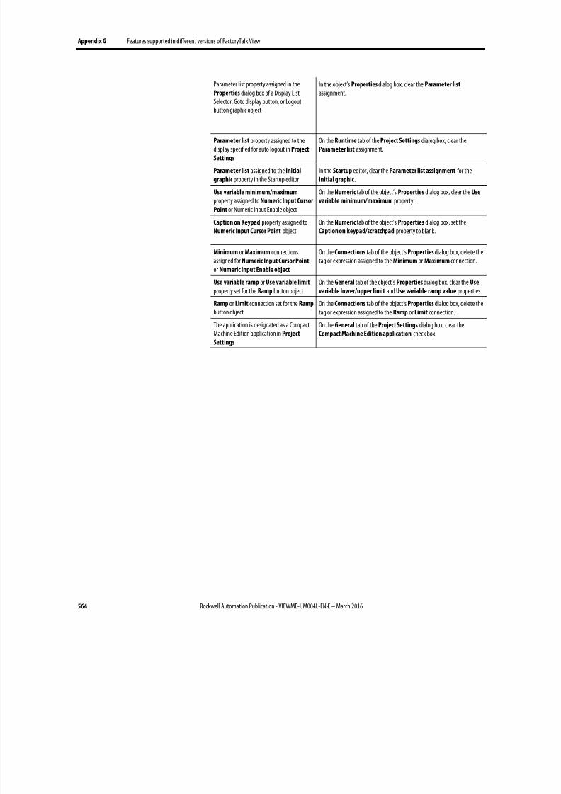
8/17/2019 FactoryTalk® View Machine Edition User's Guide
http://slidepdf.com/reader/full/factorytalk-view-machine-edition-users-guide 564/587
Appendix G Features supported in different versions of FactoryTalk View
564 Rockwell Automation Publication - VIEWME-UM004L-EN-E – March 2016
Parameter list property assigned in theProperties dialog box of a Display ListSelector, Goto display button, or Logoutbutton graphic object
In the object’s Properties dialog box, clear the Parameter list
assignment.
Parameter list property assigned to thedisplay specified for auto logout in Project
Settings
On the Runtime tab of the Project Settings dialog box, clear theParameter list assignment.
Parameter list assigned to the Initial
graphic property in the Startup editorIn the Startup editor, clear the Parameter list assignment for theInitial graphic.
Use variable minimum/maximum property assigned to Numeric Input Cursor
Point or Numeric Input Enable object
On the Numeric tab of the object’s Properties dialog box, clear the Use
variable minimum/maximum property.
Caption on Keypad property assigned toNumeric Input Cursor Point object
On the Numeric tab of the object’s Properties dialog box, set theCaption on keypad/scratchpad property to blank.
Minimum or Maximum connectionsassigned for Numeric Input Cursor Point or Numeric Input Enable object
On the Connections tab of the object’s Properties dialog box, delete thetag or expression assigned to the Minimum or Maximum connection.
Use variable ramp or Use variable limit property set for the Ramp button object
On the General tab of the object’s Properties dialog box, clear the Use
variable lower/upper limit and Use variable ramp value properties.
Ramp or Limit connection set for the Ramp
button objectOn the Connections tab of the object’s Properties dialog box, delete thetag or expression assigned to the Ramp or Limit connection.
The application is designated as a CompactMachine Edition application in Project
Settings
On the General tab of the Project Settings dialog box, clear theCompact Machine Edition application check box.

8/17/2019 FactoryTalk® View Machine Edition User's Guide
http://slidepdf.com/reader/full/factorytalk-view-machine-edition-users-guide 565/587
Rockwell Automation Publication - VIEWME-UM004L-EN-E – March 2016 565
Appendix H
Import and export graphics XML files
This appendix describes:
• Create graphics XML files
• Export, edit, and import XML files
• The graphics XML file structure
XML is the Extensible Markup Language used to create documents withstructured text information. It has a standardized format and structure. You canuse XML to edit the elements and attributes needed to create an alarm setup file orto modify graphic displays and global displays. For information about working with alarm XML files, see Import and export alarm XML files on page 553.
Sometimes editing your display information in an XML file is quicker than working in FactoryTalk View. For example, if you have a list of 100 local messagesto set up for a graphic display, you might prefer to enter all the information in atext editor, and then import the display information into FactoryTalk View.
For more information about XML, see the World Wide Web Consortium’s web page about XML at: http://www.w3.org/XML/.
The quickest way to create an XML file for your application’s graphic displays isto export the data from FactoryTalk View. You can then open the XML file inNotepad, make your changes, and import the file back into FactoryTalk View.
Tip: The strings for the application’s current language are exported to the XML file. To exportstrings for another language, reopen the application in the new language and repeat theXML export.
To export graphic display information to an XML file
1. In the Explorer window, right-click the Displays editor or the Global
Objects editor.
2. Select Import and Export.
The Graphics Import Export Wizard opens.
About XML
Create graphics XML files by
exporting
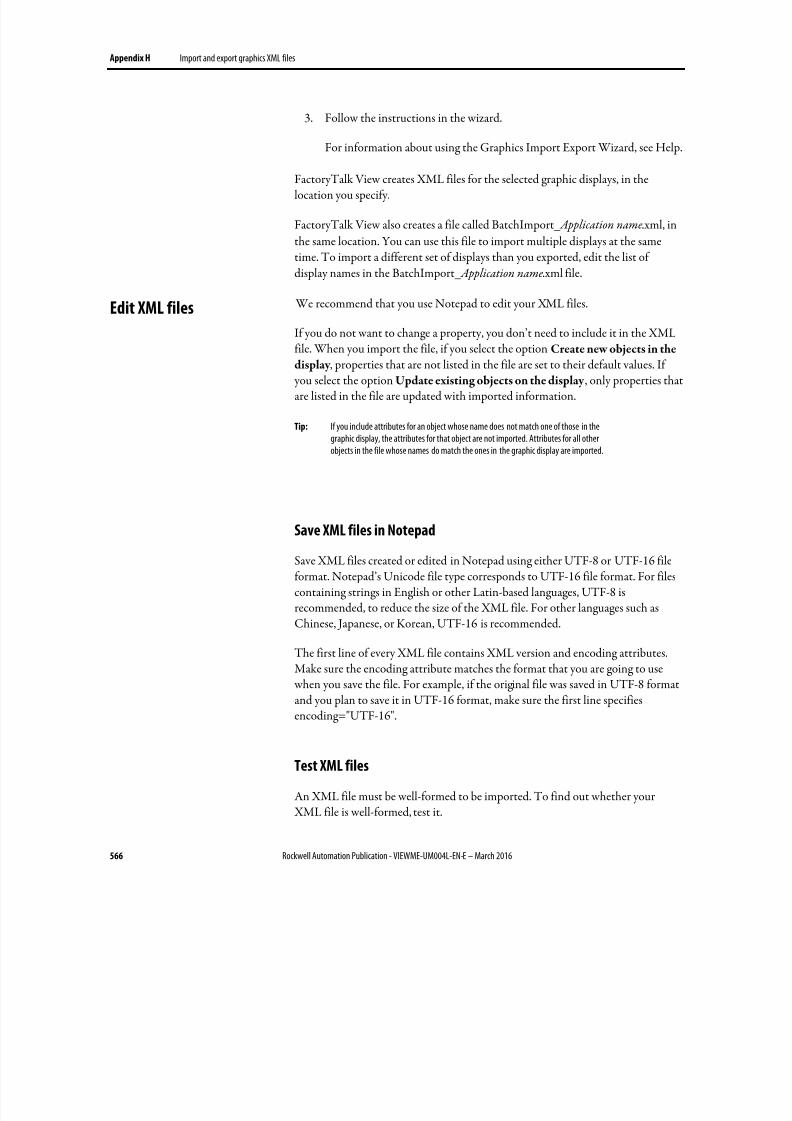
8/17/2019 FactoryTalk® View Machine Edition User's Guide
http://slidepdf.com/reader/full/factorytalk-view-machine-edition-users-guide 566/587
Appendix H Import and export graphics XML files
566 Rockwell Automation Publication - VIEWME-UM004L-EN-E – March 2016
3. Follow the instructions in the wizard.
For information about using the Graphics Import Export Wizard, see Help.
FactoryTalk View creates XML files for the selected graphic displays, in thelocation you specify.
FactoryTalk View also creates a file called BatchImport_ Application name.xml, in
the same location. You can use this file to import multiple displays at the sametime. To import a different set of displays than you exported, edit the list ofdisplay names in the BatchImport_ Application name.xml file.
We recommend that you use Notepad to edit your XML files.
If you do not want to change a property, you don’t need to include it in the XML
file. When you import the file, if you select the option Create new objects in thedisplay , properties that are not listed in the file are set to their default values. If you select the option Update existing objects on the display , only properties thatare listed in the file are updated with imported information.
Tip: If you include attributes for an object whose name does not match one of those in thegraphic display, the attributes for that object are not imported. Attributes for all otherobjects in the file whose names do match the ones in the graphic display are imported.
Save XML files in Notepad
Save XML files created or edited in Notepad using either UTF-8 or UTF-16 fileformat. Notepad’s Unicode file type corresponds to UTF-16 file format. For filescontaining strings in English or other Latin-based languages, UTF-8 isrecommended, to reduce the size of the XML file. For other languages such asChinese, Japanese, or Korean, UTF-16 is recommended.
The first line of every XML file contains XML version and encoding attributes.Make sure the encoding attribute matches the format that you are going to use when you save the file. For example, if the original file was saved in UTF-8 format
and you plan to save it in UTF-16 format, make sure the first line specifiesencoding="UTF-16".
Test XML files
An XML file must be well-formed to be imported. To find out whether your XML file is well-formed, test it.
Edit XML files
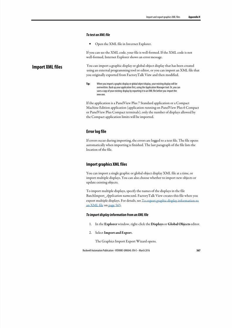
8/17/2019 FactoryTalk® View Machine Edition User's Guide
http://slidepdf.com/reader/full/factorytalk-view-machine-edition-users-guide 567/587
Import and export graphics XML files Appendix H
Rockwell Automation Publication - VIEWME-UM004L-EN-E – March 2016 567
To test an XML file
• Open the XML file in Internet Explorer.
If you can see the XML code, your file is well-formed. If the XML code is not well-formed, Internet Explorer shows an error message.
You can import a graphic display or global object display that has been createdusing an external programming tool or editor, or you can import an XML file that
you originally exported from FactoryTalk View and then modified.
Tip: When you import a graphic display or global object display, your existing display will beoverwritten. Back up your application first, using the Application Manager tool. Or, you cansave a copy of your existing display by exporting it to an XML file before you import thenew one.
If the application is a PanelView Plus 7 Standard application or a CompactMachine Edition application (application running on PanelView Plus 6 Compactor PanelView Plus Compact terminals), only the number of displays allowed bythe Compact application limits will be imported.
Error log file
If errors occur during importing, the errors are logged to a text file. The file opensautomatically when importing is finished. The last paragraph of the file lists thelocation of the file.
Import graphics XML files
You can import a single graphic or global object display XML file at a time, orimport multiple displays. You can also choose whether to import new objects orupdate existing objects.
To import multiple displays, specify the names of the displays in the file
BatchImport_ Application name.xml. FactoryTalk View creates this file when you
export multiple displays. For details, see To export graphic display information toan XML file on page 565.
To import display information from an XML file
1. In the Explorer window, right-click the Displays or Global Objects editor.
2. Select Import and Expor t.
The Graphics Import Export Wizard opens.
Import XML files

8/17/2019 FactoryTalk® View Machine Edition User's Guide
http://slidepdf.com/reader/full/factorytalk-view-machine-edition-users-guide 568/587
Appendix H Import and export graphics XML files
568 Rockwell Automation Publication - VIEWME-UM004L-EN-E – March 2016
3. Follow the instructions in the wizard.
For more information about using the Graphics Import Export Wizard, see
Help.
The graphic display or global object display XML file is a FactoryTalk View XMLdocument that describes the objects and settings for a display. The root element ofthe XML document is called gfx . It represents the display. An XML document cancontain only one root element. All other elements in the document must becontained or nested within the root element.
In an XML document, the start of an element is marked <element name>. Theend is marked </element name>.
If the element contains no subelements, the end can be marked />. For example,
<caption fontFamily="Arial" fontSize="8" bold="false" />.
The syntax for specifying an attribute for an element is attribute="value" . Theattribute value must be enclosed in single or double quotes.
Here is a sample structure for a graphic display XML document containing twographic objects. The second object has states:
Graphics XML file structure
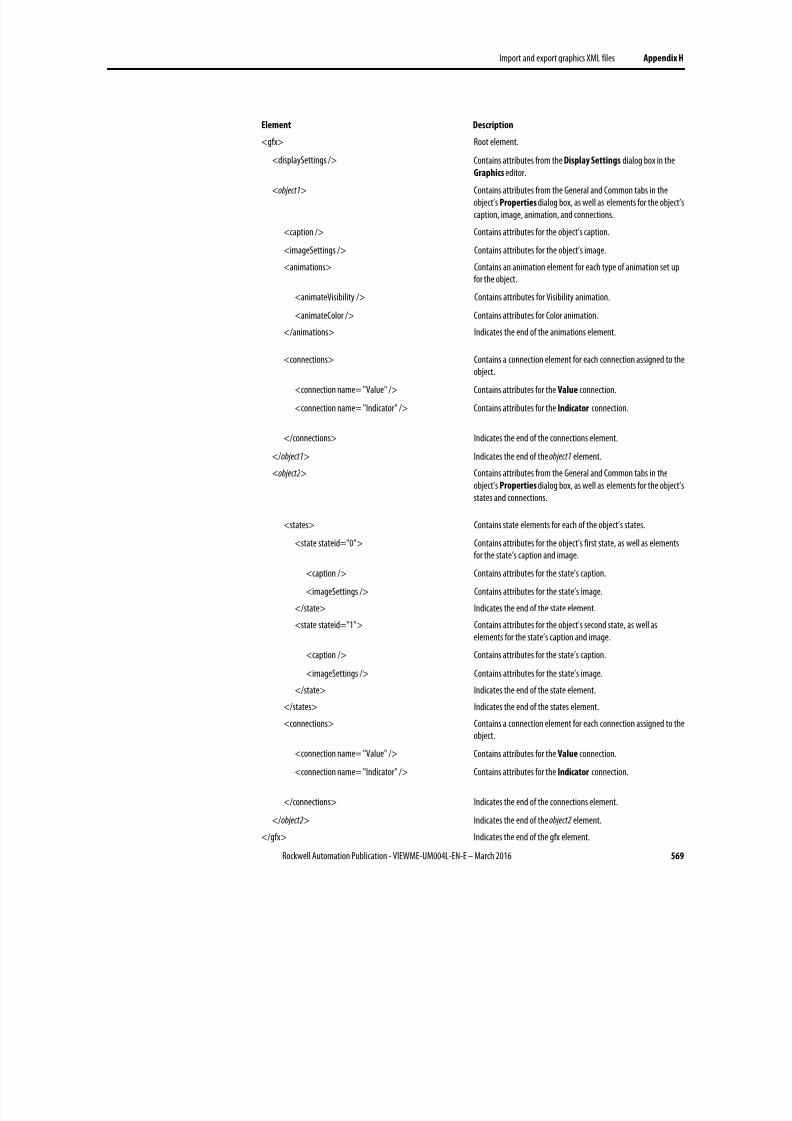
8/17/2019 FactoryTalk® View Machine Edition User's Guide
http://slidepdf.com/reader/full/factorytalk-view-machine-edition-users-guide 569/587
Import and export graphics XML files Appendix H
Rockwell Automation Publication - VIEWME-UM004L-EN-E – March 2016 569
Element Description
<gfx> Root element.
<displaySettings /> Contains attributes from the Display Settings dialog box in the
Graphics editor.<object1> Contains attributes from the General and Common tabs in the
object’s Properties dialog box, as well as elements for the object’scaption, image, animation, and connections.
<caption /> Contains attributes for the object’s caption.
<imageSettings /> Contains attributes for the object’s image.
<animations> Contains an animation element for each type of animation set upfor the object.
<animateVisibility /> Contains attributes for Visibility animation.
<animateColor /> Contains attributes for Color animation.
</animations> Indicates the end of the animations element.
<connections> Contains a connection element for each connection assigned to theobject.
<connection name= "Value" /> Contains attributes for the Value connection.
<connection name= "Indicator" /> Contains attributes for the Indicator connection.
</connections> Indicates the end of the connections element.
</object1> Indicates the end of the object1 element.
<object2> Contains attributes from the General and Common tabs in theobject’s Properties dialog box, as well as elements for the object’sstates and connections.
<states> Contains state elements for each of the object’s states.
<state stateid="0"> Contains attributes for the object’s first state, as well as elementsfor the state’s caption and image.
<caption /> Contains attributes for the state’s caption.
<imageSettings /> Contains attributes for the state’s image.
</state> Indicates the end of the state element.
<state stateid="1"> Contains attributes for the object’s second state, as well aselements for the state’s caption and image.
<caption /> Contains attributes for the state’s caption.
<imageSettings /> Contains attributes for the state’s image.
</state> Indicates the end of the state element.
</states> Indicates the end of the states element.
<connections> Contains a connection element for each connection assigned to theobject.
<connection name= "Value" /> Contains attributes for the Value connection.
<connection name= "Indicator" /> Contains attributes for the Indicator connection.
</connections> Indicates the end of the connections element.
</object2> Indicates the end of the object2 element.
</gfx> Indicates the end of the gfx element.

8/17/2019 FactoryTalk® View Machine Edition User's Guide
http://slidepdf.com/reader/full/factorytalk-view-machine-edition-users-guide 570/587
Appendix H Import and export graphics XML files
570 Rockwell Automation Publication - VIEWME-UM004L-EN-E – March 2016
You can specify multiple attributes for an element. For example, the captionelement contains 13 possible attributes.
Elements for group objects begin with <group> and end with </group>. The
<group> element contains all the elements for each object in the group.
For more information about graphic object elements and their attributes, see Helpfor the Graphics Import Export Wizard.
8/17/2019 FactoryTalk® View Machine Edition User's Guide
http://slidepdf.com/reader/full/factorytalk-view-machine-edition-users-guide 571/587
Rockwell Automation Publication - VIEWME-UM004L-EN-E – March 2016 571
.
.bmp files 329
import 330
location of 330
place in graphic displays 355
tips for using 334
view 331
.dxf files 329
place in graphic displays 362
.jpg files 329
import 330
place in graphic displays 355
tips for using 334
view 331
.mea files 70
.med files 59
.mer files 60
compare 256
convert to .med 225, 228
create 223
transfer 234, 250, 255, 256
.wmf files 329
place in graphic displays 362
.xml files 122, 312, 563
A
A.I. 5 tags
import 108
AB_DF1-1
use to transfer applications 254
AB_ETH-1
use to transfer applications 254
Acknowledge alarm button graphic object 347
use with alarm objects 125, 153
Acknowledge all alarms button graphic object 125, 347
use with alarm lists 153
ActiveX objects 341, 362
animate 426
at runtime 298
create 363
navigate to 414
use to display tag values 346, 349
use to set tag values 345, 349
Address syntax
for HMI tags 102
Logix5000 103
Adobe Reader 34
ALARM BANNER display 144
edit 144
Alarm banner graphic object 350
at run time 152, 300
link buttons to 416
navigate to 414
specify time and date format for 246
use buttons with 153
ALARM display 124
open and close 143, 144, 149
Alarm Import Export Wizard 563
Alarm list graphic object 350
at run time 150, 300
link buttons to 416
navigate to 414
specify time and date format for 246
use buttons with 153
Alarm log file 60, 128
delete at application startup 245
print contents of 128
Alarm messages
embedded variables in 462
export to XML 563
handshake 139
import XML 565
multiple languages for 123, 135
print at runtime 128
view at run time 300
ALARM MULTI-LINE display 124
copy 148
edit 145
Alarm Setup editor
export to XML 563
import XML 565
use tags in 376
Alarm status list graphic object 350
at run time 152
link buttons to 416
navigate to 414
use buttons with 153
Alarm status mode button graphic object 347
Index
8/17/2019 FactoryTalk® View Machine Edition User's Guide
http://slidepdf.com/reader/full/factorytalk-view-machine-edition-users-guide 572/587
Index
572 Rockwell Automation Publication - VIEWME-UM004L-EN-E – March 2016
use with alarm status lists 153
Alarm triggers 122
and the default language 123
data types for 129, 133
export to XML 563
import XML 565
Alarms 119
acknowledge 125, 136, 137, 139, 143, 156
clear 126, 157
create your own display for 149
delete 157
expressions in 445
filter 123
handshake 136, 139
import and export 122, 312
keep a permanent record of 123, 128
notification methods for 123
plan 56
print at runtime 128
queue 136
reset status of 127, 143, 158
respond to 125
retain status of 158
send messages to the data source 141
set up 120
show 124
show in the alarm status list 158
silence 127, 142, 157
sort 127, 158
test on the development computer 223
Analog tags 97
how floating-point values are rounded 98
log values for 490
monitor for alarms 121
use to generate a range of alarms 129
Animation 425
check 440
copy 441
define range of motion for 430
for global objects 442, 481
for group objects 388, 439
set minimum and maximum values for 430
test 428
use expressions 443
use Object Smart Path 428, 431
use tags and placeholders 429
view in Object Explorer 367
Animation dialog box 426
Animation types 425
color 433
fill 436
height 438
horizontal position 437
horizontal slider 438
rotation 438
vertical position 437
vertical slider 439
visibility 432
width 437
Application Explorer 39, 40
show and hide 43
use 43
Application files
convert from runtime to development 225, 228
delete from disk 307
view location of 76
Application Manager 70
convert .mer files to .med files 228
security for 70
Application properties
view 76
Application text
export for translation 204
import 211
translate in Excel 207
translate in Unicode 207
Applications 37
backe up and restore 70
close 69
compare 256
convert 531, 547
copy, delete, and rename 70
create 62
multiple version support for 69, 571
open 38, 66, 68
plan 51
runtime, create 224
sample, grant users access to 38
sample, open 38
security for 197
specify language for 62, 533
test on the development computer 223
8/17/2019 FactoryTalk® View Machine Edition User's Guide
http://slidepdf.com/reader/full/factorytalk-view-machine-edition-users-guide 573/587
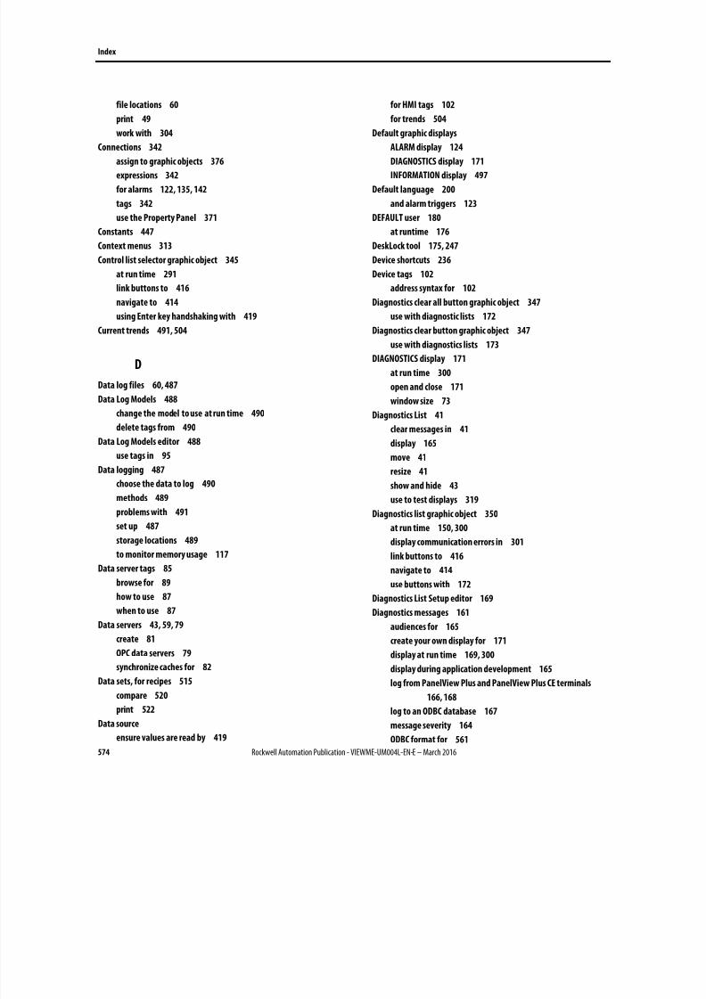
8/17/2019 FactoryTalk® View Machine Edition User's Guide
http://slidepdf.com/reader/full/factorytalk-view-machine-edition-users-guide 574/587
Index
574 Rockwell Automation Publication - VIEWME-UM004L-EN-E – March 2016
file locations 60
print 49
work with 304
Connections 342
assign to graphic objects 376
expressions 342
for alarms 122, 135, 142
tags 342
use the Property Panel 371
Constants 447
Context menus 313
Control list selector graphic object 345
at run time 291
link buttons to 416
navigate to 414
using Enter key handshaking with 419
Current trends 491, 504
D
Data log files 60, 487
Data Log Models 488
change the model to use at run time 490
delete tags from 490
Data Log Models editor 488
use tags in 95
Data logging 487
choose the data to log 490
methods 489
problems with 491
set up 487
storage locations 489
to monitor memory usage 117
Data server tags 85
browse for 89
how to use 87
when to use 87
Data servers 43, 59, 79
create 81
OPC data servers 79
synchronize caches for 82
Data sets, for recipes 515
compare 520
print 522
Data source
ensure values are read by 419
for HMI tags 102
for trends 504
Default graphic displays
ALARM display 124
DIAGNOSTICS display 171
INFORMATION display 497
Default language 200
and alarm triggers 123
DEFAULT user 180
at runtime 176
DeskLock tool 175, 247
Device shortcuts 236
Device tags 102
address syntax for 102
Diagnostics clear all button graphic object 347
use with diagnostic lists 172
Diagnostics clear button graphic object 347
use with diagnostics lists 173
DIAGNOSTICS display 171
at run time 300
open and close 171
window size 73
Diagnostics List 41
clear messages in 41
display 165
move 41
resize 41
show and hide 43
use to test displays 319
Diagnostics list graphic object 350
at run time 150, 300
display communication errors in 301
link buttons to 416
navigate to 414
use buttons with 172
Diagnostics List Setup editor 169
Diagnostics messages 161
audiences for 165
create your own display for 171
display at run time 169, 300
display during application development 165
log from PanelView Plus and PanelView Plus CE terminals
166, 168
log to an ODBC database 167
message severity 164
ODBC format for 561
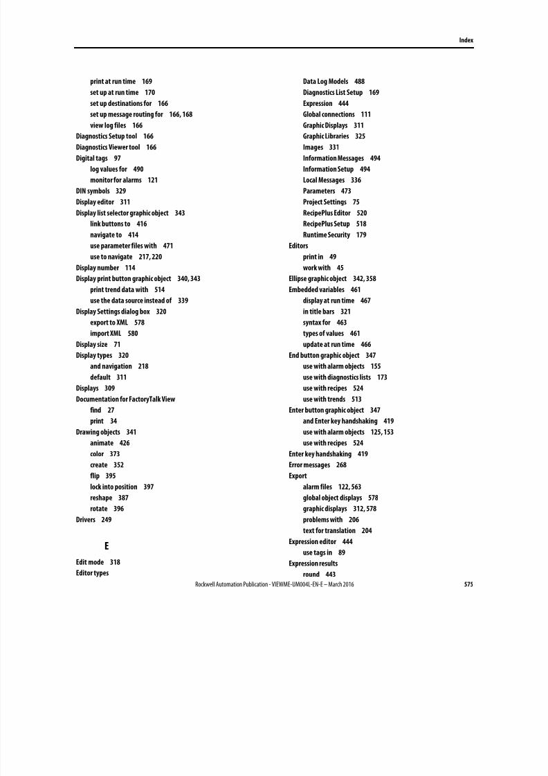
8/17/2019 FactoryTalk® View Machine Edition User's Guide
http://slidepdf.com/reader/full/factorytalk-view-machine-edition-users-guide 575/587
Index
Rockwell Automation Publication - VIEWME-UM004L-EN-E – March 2016 575
print at run time 169
set up at run time 170
set up destinations for 166
set up message routing for 166, 168
view log files 166
Diagnostics Setup tool 166
Diagnostics Viewer tool 166
Digital tags 97
log values for 490
monitor for alarms 121
DIN symbols 329
Display editor 311
Display list selector graphic object 343
link buttons to 416
navigate to 414
use parameter files with 471
use to navigate 217, 220
Display number 114
Display print button graphic object 340, 343
print trend data with 514
use the data source instead of 339
Display Settings dialog box 320
export to XML 578
import XML 580
Display size 71
Display types 320
and navigation 218
default 311
Displays 309
Documentation for FactoryTalk View
find 27
print 34
Drawing objects 341
animate 426
color 373
create 352
flip 395
lock into position 397
reshape 387
rotate 396
Drivers 249
E
Edit mode 318
Editor types
Data Log Models 488
Diagnostics List Setup 169
Expression 444
Global connections 111
Graphic Displays 311
Graphic Libraries 325
Images 331
Information Messages 494
Information Setup 494
Local Messages 336
Parameters 473
Project Settings 75
RecipePlus Editor 520
RecipePlus Setup 518
Runtime Security 179
Editors
print in 49
work with 45
Ellipse graphic object 342, 358
Embedded variables 461
display at run time 467
in title bars 321
syntax for 463
types of values 461
update at run time 466
End button graphic object 347
use with alarm objects 155
use with diagnostics lists 173
use with recipes 524
use with trends 513
Enter button graphic object 347
and Enter key handshaking 419
use with alarm objects 125, 153
use with recipes 524
Enter key handshaking 419
Error messages 268
Export
alarm files 122, 563
global object displays 578
graphic displays 312, 578
problems with 206
text for translation 204
Expression editor 444
use tags in 89
Expression results
round 443
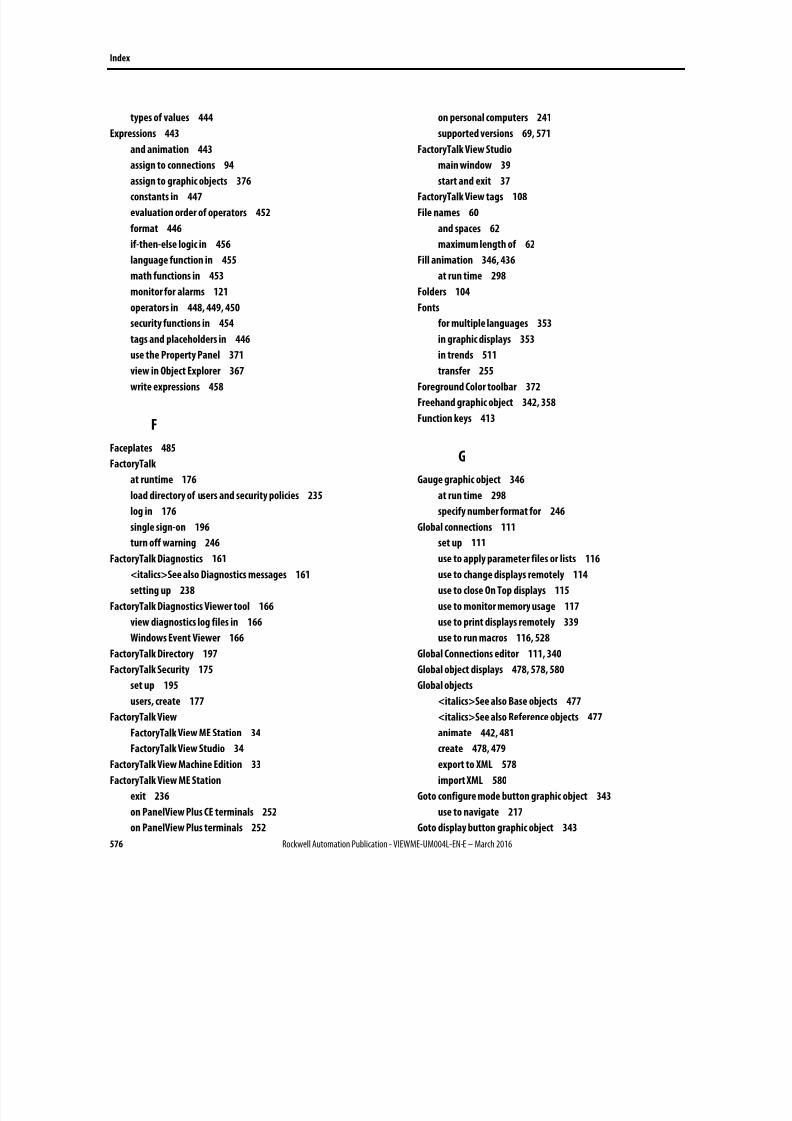
8/17/2019 FactoryTalk® View Machine Edition User's Guide
http://slidepdf.com/reader/full/factorytalk-view-machine-edition-users-guide 576/587
Index
576 Rockwell Automation Publication - VIEWME-UM004L-EN-E – March 2016
types of values 444
Expressions 443
and animation 443
assign to connections 94
assign to graphic objects 376
constants in 447
evaluation order of operators 452
format 446
if-then-else logic in 456
language function in 455
math functions in 453
monitor for alarms 121
operators in 448, 449, 450
security functions in 454
tags and placeholders in 446
use the Property Panel 371
view in Object Explorer 367
write expressions 458
F
Faceplates 485
FactoryTalk
at runtime 176
load directory of users and security policies 235
log in 176
single sign-on 196
turn off warning 246
FactoryTalk Diagnostics 161
<italics>See also Diagnostics messages 161
setting up 238
FactoryTalk Diagnostics Viewer tool 166
view diagnostics log files in 166
Windows Event Viewer 166
FactoryTalk Directory 197
FactoryTalk Security 175
set up 195
users, create 177
FactoryTalk View
FactoryTalk View ME Station 34
FactoryTalk View Studio 34
FactoryTalk View Machine Edition 33
FactoryTalk View ME Station
exit 236
on PanelView Plus CE terminals 252
on PanelView Plus terminals 252
on personal computers 241
supported versions 69, 571
FactoryTalk View Studio
main window 39
start and exit 37
FactoryTalk View tags 108
File names 60
and spaces 62
maximum length of 62
Fill animation 346, 436
at run time 298
Folders 104
Fonts
for multiple languages 353
in graphic displays 353
in trends 511
transfer 255
Foreground Color toolbar 372
Freehand graphic object 342, 358
Function keys 413
G
Gauge graphic object 346
at run time 298
specify number format for 246
Global connections 111
set up 111
use to apply parameter files or lists 116
use to change displays remotely 114
use to close On Top displays 115
use to monitor memory usage 117
use to print displays remotely 339
use to run macros 116, 528
Global Connections editor 111, 340
Global object displays 478, 578, 580
Global objects
<italics>See also Base objects 477
<italics>See also Reference objects 477
animate 442, 481
create 478, 479
export to XML 578
import XML 580
Goto configure mode button graphic object 343
use to navigate 217
Goto display button graphic object 343
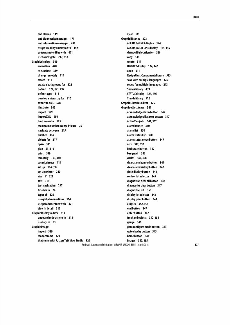
8/17/2019 FactoryTalk® View Machine Edition User's Guide
http://slidepdf.com/reader/full/factorytalk-view-machine-edition-users-guide 577/587
Index
Rockwell Automation Publication - VIEWME-UM004L-EN-E – March 2016 577
and alarms 149
and diagnostics messages 171
and information messages 499
assign visibility animation to 192
use parameter files with 471
use to navigate 217, 218
Graphic displays 309
animation 428
at run time 339
change remotely 114
create 311
create a background for 322
default 124, 171, 497
default type 311
develop a hierarchy for 216
export to XML 578
illustrate 342
import 329
import XML 580
limit access to 185
maximum number licensed to use 76
navigate between 215
number 114
objects for 217
open 311
plan 53, 310
print 339
remotely 339, 340
security issues 114
set up 114, 399
set up printer 240
size 71, 321
test 318
test navigation 217
title bar in 74
types of 320
use global connections 114
use parameter files with 471
view in detail 317
Graphic Displays editor 311
undo and redo actions in 318
use tags in 93
Graphic images
import 329
monochrome 329
that come with FactoryTalk View Studio 329
view 331
Graphic libraries 323
ALARM BANNER display 144
ALARM MULTI-LINE display 124, 145
change file location for 328
copy 148
create 311
HISTORY display 124, 147
open 311
RecipePlus_Components library 523
save with multiple languages 326
set up for multiple languages 213
Sliders library 439
STATUS display 124, 146
Trends library 512
Graphic Libraries editor 325
Graphic object types 341
acknowledge alarm button 347
acknowledge all alarms button 347
ActiveX objects 341, 362
alarm banner 350
alarm list 350
alarm status list 350
alarm status mode button 347
arcs 342, 357
backspace button 347
bar graph 346
circles 342, 358
clear alarm banner button 347
clear alarm history button 347
close display button 343
control list selector 345
diagnostics clear all button 347
diagnostics clear button 347
diagnostics list 350
display list selector 343
display print button 343
ellipses 342, 358
end button 347
enter button 347
freehand objects 342, 358
gauge 346
goto configure mode button 343
goto display button 343
home button 347
images 342, 355
8/17/2019 FactoryTalk® View Machine Edition User's Guide
http://slidepdf.com/reader/full/factorytalk-view-machine-edition-users-guide 578/587
Index
578 Rockwell Automation Publication - VIEWME-UM004L-EN-E – March 2016
information acknowledge button 347
information message display 350
interlocked push button 345
language switch button 343
latched push button 345
lines 342, 359
list indicator 346
local message display 350
login button 343
logout button 343
maintained push button 345
momentary push button 345
move down button 347
move left button 347
move right button 347
move up button 347
multistate indicator 346
multistate push button 345
next pen button 347
numeric display 349
numeric input cursor point 349
numeric input enable button 349
page down button 347
page up button 347
panels 342, 356
password button 343
pause button 347
piloted control list selector 345
polygons 342, 359
polylines 342, 359
print alarm history button 343
print alarm status button 343
ramp button 345
RecipePlus button 349, 517
RecipePlus selector 349, 516
RecipePlus table 349, 516
rectangles 342, 360
reset alarm status mode button 347
return to display button 343
rounded rectangles 342, 361
scale 346
shutdown button 343
silence alarms button 347
sort alarms button 347
squares 342, 360
string display 349
string input enable button 349
symbol 346
text 342, 353
time and date display 346
trend 346
wedges 342, 357
Graphic objects 309
align 392
animate 426
arrange 391, 394
assign connections to 371, 376
color 372
convert to wallpaper 322
copy 383
create 325, 351, 352
delete 388
deselect 364
duplicate 385
edit 381
embedded variables in 462
export to XML 578
group and ungroup 388
import XML 580
move 381
name 374
navigate between 414
position 316, 391
replace tags and expressions in 378
resize 385
select 364
set up 399
spatial properties of 409
time, date, and number formats 423
use at run time 411
use keys to work with 386
use the Properties dialog box 368
use the Property Panel 371
use to display alarms and messages 350
use to display processes 346
use to enter and display numeric and string values 349
use to illustrate displays 342
use to navigate 217
use to start and control processes 345
visibility, setting up 409
Grid
in graphic displays 316
8/17/2019 FactoryTalk® View Machine Edition User's Guide
http://slidepdf.com/reader/full/factorytalk-view-machine-edition-users-guide 579/587
Index
Rockwell Automation Publication - VIEWME-UM004L-EN-E – March 2016 579
in trends 511
Group objects
animate 388, 439
create 388
edit 390
name 374
H
Handshake
Enter key 419
for Alarm messages 139
for alarms 136
remote 139
Height animation 346, 438
at run time 298
Historical trends 491, 504
HISTORY display 124
edit 147
HMI servers 43, 59
HMI tags 86, 97
<italics>See also 97
address syntax for 102
browse for 89
create 105
data sources 102
export 108
how to use 89
import 107, 108
merge databases 108
name 104
search for 100
when to use 88
Home button graphic object 347
use with alarm objects 155
use with diagnostics lists 173
use with recipes 524
use with trends 513
Horizontal position animation 346, 437
at run time 298
Horizontal slider animation 346, 431, 438
at run time 291
I
If-then-else logic
in expressions 456
nest 457
Image Browser 332
Image graphic object 342, 355
Images editor 331
Import
alarm files 122, 565
applications 63
global object displays 579
graphic displays 312
tags 108
Import application text 211
problems with 212
Information acknowledge button graphic object 347
at run time 498
INFORMATION display 497
at run time 300
open and close 499
window size 73
Information message display graphic object 350
at run time 300, 499
Information message files 494, 495
change the file to use at run time 500
Information messages 493
create your own display for 498
display 494
embedded variables in 462
multiple languages for 497
set up 493
view at run time 300
Information Messages editor 494
Information Setup editor 494
Ingredients, for recipes 515
Initial values for tags 527
Input focus 414
Interlocked push button graphic object 345
at run time 291
ISA symbols 329
Isolated graphing 510
K
KEPServerEnterprise 135
Keyboard button symbols 329
Keyboard navigation 414
8/17/2019 FactoryTalk® View Machine Edition User's Guide
http://slidepdf.com/reader/full/factorytalk-view-machine-edition-users-guide 580/587
Index
580 Rockwell Automation Publication - VIEWME-UM004L-EN-E – March 2016
L
Language function 455
Language strings
export for translation 204import 211
translate in Excel 207
translate in Unicode file 207
Language switch button graphic object 201, 343
place in displays 217
plan 55
Language switching 199
<italics>See also Languages 199
set up 201
set up Windows for 202
Languagesadd 203
choose fonts for 353
default 200
display current language 455
display navigation 217
plan 55
RFC1766 names 567
set up in runtime application 226
set up messages 123, 135, 338, 455, 497
test 224
to libraries 326Latched push button graphic object 345
at run time 291
Least Significant Bit trigger type 131
Libraries 323
License 76
Line graphic object 342, 359
Link properties 481
List indicator graphic object 346
at run time 298
Local message display graphic object 336, 350
at run time 300, 339use with message files 335
Local message files 336
Local messages 335
embedded variables in 462
multiple languages for 338
view at run time 300
Local Messages editor 336
Localize applications
import text 211
information for translators 207
new line character 210
problems importing text 212
Unicode file schema 209
Log files 561
LOGIC 5 108
Logical operators 449, 452
evaluation order of 452
Login button graphic object 343
locat in display hierarchy 216
log in with 186
Login macro 528, 529
assign to RSView 3.20 and earlier users 183
assign to users 179, 180, 182
run 186, 268
Login window 266
Logix5000 faceplates 485
Logix5000 processors 86
address syntax for 102
create tags in 87
Logout button graphic object 343
locat in display hierarchy 216
log out with 186
Logout macro 528, 529
assign to RSView 3.20 and earlier users 183
assign to users 179, 180, 182
run 186, 268
LSBit trigger type 131
M
Macro button graphic object
use to run macros 528
Macros
create 527
run from the data source 116, 528
Macros editor 527
Maintained push button graphic object 345, 458
at run time 291
Math functions 453
Memory tags 102
use 89
Memory usage 117
Menus 313
Message severity 164
8/17/2019 FactoryTalk® View Machine Edition User's Guide
http://slidepdf.com/reader/full/factorytalk-view-machine-edition-users-guide 581/587
Index
Rockwell Automation Publication - VIEWME-UM004L-EN-E – March 2016 581
Messages
<italics>See also 119, 161, 335, 493
display 350
in RSView ME Station 4.00 455
plan 56
Microsoft Access
log to 167
Microsoft Excel
export text strings to 204
translate text strings in 207
Microsoft SQL Server 167
Minimum and maximum values
for animation 430
for HMI tags 88
for trends 508
Momentary push button graphic object 345
at run time 291
Monochrome images 329, 346
Move down button graphic object 347
set up auto repeat for 418
use with alarm objects 155
use with diagnostic lists 172
use with recipes 524
use with trends 513
Move left button graphic object 347
set up auto repeat for 418
use with trends 513
Move right button graphic object 347
set up auto repeat for 418
use with trends 513
Move up button graphic object 347
set up auto repeat for 418
use with alarm objects 155
use with diagnostics lists 173
use with recipes 524
use with trends 513
Multistate graphic objects
color 372
set up 403
test states 375
Multistate indicator graphic object 346
at run time 298
use with recipes 523
Multistate push button graphic object 345
at run time 291
set up auto repeat for 418
N
Navigation
between graphic displays 215
between graphic objects in a display 414test navigation 217
Next pen button graphic object 347
use to change trend's vertical axis labels 508
Number format 246
Numeric display graphic object 349, 512
at run time 298
specify number format for 246
Numeric embedded variables 463
at runtime 467
Numeric input cursor point graphic object 349
at run time 291, 298navigate to 414
use Enter key handshaking with 419
Numeric input enable button graphic object 349
at run time 291
how values are calculated 285
how values are ramped 284
navigate to 414
use Enter key handshaking with 419
use write expressions with 458
Numeric pop-up windows
use at run time 283Numeric values
ramp at run time 282
use graphic objects to display and enter 349
O
Object Explorer 365
open 366
use to highlight objects 367
view animation in 367
view tag and expression assignments in 367Object Smart Path 428, 431
ODBC storage format 561
Off-line tags 91
OLE for Process Control 79
On Top displays 321
size 72
use for alarms 149
use for diagnostics messages 171
8/17/2019 FactoryTalk® View Machine Edition User's Guide
http://slidepdf.com/reader/full/factorytalk-view-machine-edition-users-guide 582/587
Index
582 Rockwell Automation Publication - VIEWME-UM004L-EN-E – March 2016
use for information messages 498
OPC communications 102
OPC servers, items in 103
OPC tags 102
open Symbol Factory, Symbol Factory 323
Operators 448
Oracle 167
P
Page down button graphic object 347
set up auto repeat for 418
use with alarm objects 155
use with diagnostics lists 173
use with recipes 524
Page up button graphic object 347
set up auto repeat for 418
use with alarm objects 155
use with diagnostics lists 173
use with recipes 524
Panel graphic object 342, 356
PanelBuilder 1400e applications 531
PanelBuilder 32 applications 547
PanelBuilder applications 547
PanelView Plus CE terminals
log diagnostics messages from 166, 168
transfer applications to 249
PanelView Plus terminals
log diagnostics messages from 166, 168
run applications on 249
transfer applications to 249
Parameter files 469
assign to graphic displays 469
in global connections 116
use display list selectors 471
use goto display buttons 471
Parameter lists
create 475
in global connections 116
in graphic objects 471
Parameter passing 477
Parameters editor 473
use tags in 89
Password button graphic object 343
use at runtime 269, 272
Passwords
at runtime 269, 272, 275, 276, 278, 279, 281
for RSView 3.20 and earlier users 183
for Windows users in RSView 3.20 and earlier applications
184
manage 196
Pause button graphic object 347
use with trends 513
Piloted control list selector graphic object 345
use Enter key handshaking with 419
Placeholders 429
PLC tags 107
Polygon graphic object 342, 359
Polyline graphic object 342, 359
Preconfigured graphic displays
ALARM display 124
DIAGNOSTICS display 171
INFORMATION display 497
Print alarm history button graphic object 343
specify time and date format for 246
use to print alarm information 128
use with alarm objects 153
Print alarm status button graphic object 343
use to print alarm information 128
use with alarm objects 153
Printers
select on the development computer 49
specify at run time on personal computers 240
type to use with PanelView Plus and PanelView Plus CE 250,
251
Problems at run time 117
communication errors 301
data logging 491
display trend data 514
log in 268
print from a PanelView Plus CE terminal 250
print from a PanelView Plus terminal 250, 251
use the numeric pop-up windows 286
use the string pop-up windows 290
Problems during application development
export text for translation 206
import alarm XML files 579
import graphics XML files 579
import text 212
navigate through displays 217
Process faceplates
add to an existing application 485
8/17/2019 FactoryTalk® View Machine Edition User's Guide
http://slidepdf.com/reader/full/factorytalk-view-machine-edition-users-guide 583/587
Index
Rockwell Automation Publication - VIEWME-UM004L-EN-E – March 2016 583
select tags for 90
Project files 76
Project Settings editor 75
Project window size 71
change 72
Projects 59
Properties dialog box
open 369
set up objects in 368
use to assign connections to graphic objects 376, 377
Property Panel
open 370
set up objects in 371
use to assign connections to graphic objects 371
R
RAM usage 117
Ramp button graphic object 345, 378
at run time 291
set up auto repeat for 418
Range of motion 430
Read connection 371
Read-write connection 371
Real-time trends 491
Recipe files
set up 520
specify location for 518
RecipePlus 515
RecipePlus button graphic object 349, 517
create 522
use at runtime 291, 298, 524
RecipePlus Editor 520
view runtime data in 525
RecipePlus selector graphic object 349, 516
create 522
link buttons to 416
navigate to 414
use at runtime 291, 298, 524
RecipePlus Setup editor 518
RecipePlus table graphic object 349, 516
create 522
link buttons to 416
navigate to 414
use at runtime 291, 298, 524
Recipes 515
compare 520
delete units 517
display at runtime 516
download 517
edit at runtime 516
link buttons to 524
number format 518
numeric limits 518
plan 57
rename units 517
save at runtime 517
select at runtime 516
set up 516
test 523
time and date formats 522
upload 517
view data for 228, 525
Rectangle graphic object 342, 360
blink 434
Reference objects
create 479
edit 481
link properties 481
Relational operators
evaluation order of 452
in expressions 449
Remote display changes 114
Remote macros 116, 528
Replace displays 320
size 72
Reset alarm status button graphic object 347
use to reset alarms 127
use with alarm status lists 153
Return to display button graphic object 343
use to navigate 217, 219
RFC1766 names 567
Right-click menus 313
Rotation animation 346, 396, 438
at run time 298
Rounded rectangle graphic object 342, 361
RSLinx Classic 34
RSLinx Enterprise 134
array tag syntax 134
device shortcuts created at runtime 225, 228
set up drivers in 239, 254
RSLogix 5 tags 108
8/17/2019 FactoryTalk® View Machine Edition User's Guide
http://slidepdf.com/reader/full/factorytalk-view-machine-edition-users-guide 584/587
Index
584 Rockwell Automation Publication - VIEWME-UM004L-EN-E – March 2016
RSLogix 500 tags 108
RSLogix 5000 86
Runtime
Automatic logout 187
change tag values 291
delete log files 245
display tag values 298
enter string values 286
font substitution 353
graphic displays 339
log in and out 186, 262, 265
print 50
print graphic displays 339
problems with logging in 268
set up communication drivers on personal computers 239
set up printers on personal computers 240
switch language at 217
time, date, and number formats 423
use graphic objects 411
view alarms and messages 300
view communication errors 301
Runtime application
.mer files 249
convert to development application 225, 228
from PanelView Plus or PanelView Plus CE 256
on PanelView Plus CE terminals 252
on PanelView Plus terminals 252
on personal computers 234, 241, 252
open 234
shut down 236
to PanelView 250, 255
to PanelView Plus CE 250, 255
to personal computers 234, 250
Runtime application file 224
Runtime RAM usage 117
Runtime screen resolution 71
Runtime Security editor 179
S
Sample applications 38
Scale graphic object 346
Screen resolution 71
Screen size 71
Security
and remote display changes 114
automatic logout 187
control who can stop the application 194
FactoryTalk Security 175
FactoryTalk View security 175
for Application Manager 70
log in and out 186
plan 57
set up 177
use visibility animation 192, 194, 432
Security codes
assign to graphic displays 185
assign to RSView 3.20 and earlier users 183
assign to users 179, 180, 182
Security functions
in expressions 454
use 192, 432
Serial downloads 255
Shutdown button graphic object 343
assign visibility animation to 193
limit access to 194
locat in display hierarchy 216
use to navigate 217, 221
use to shut down application 236
use to stop application 224
Shutdown macro 528, 529
Silence alarms button graphic object 127
use with alarm objects 153
Single sign-on 196
SLC tags 107
Sort alarms button graphic object 127, 347
use with alarm lists 153
Special keys
arrows, use with graphic objects 386
copy objects with 383
draw objects with 358, 359, 360, 361
resize objects with 386
rotate objects with 396
select objects with 365
Shift, use with graphic objects 386
use to navigate at run time 415
use with numeric pop-up windows 284
use with string pop-up windows 289
Spreadsheets, work in 47
Square graphic object 342, 360
Standard toolbar 40
Startup macro 528, 529
8/17/2019 FactoryTalk® View Machine Edition User's Guide
http://slidepdf.com/reader/full/factorytalk-view-machine-edition-users-guide 585/587
Index
Rockwell Automation Publication - VIEWME-UM004L-EN-E – March 2016 585
Startup settings 223
States 341
States toolbar 375
Status bar 42
show and hide 43
STATUS display 124
copy 148
edit 146
String display graphic object 349
at run time 298
String embedded variables 464
at runtime 468
String input enable button graphic object 349
at run time 286, 291
how values are written 290
navigate to 414
use Enter key handshaking with 419
String pop-up character input
use at run time 287
String pop-up windows 283
String tags 97
String values 349
Structured tags 90, 482
Sybase SQL Server 167
Symbol Factory 323, 333
import into display 333
import into image container 333
Symbol graphic object 346
at run time 298
Syntax, embedded variable 463
System activity 161
System tags 97
alarm reset date and time 559
for making graphic objects blink 559
time and date 559
System time and date 559
T
Tag Browser
open 89
use 90
Tag Import and Export Wizard 108
Tag placeholders 469, 472
create 380
use in expressions 446
use with animation 429
Tag sets, for recipes 515
compare 520
Tag statistics 105
Tag substitution 95, 378
Tag syntax
KEPServerEnterprise 135
RSLinx Enterprise 134
Tag values
change at run time 291
display at run time 298
ensure the data source has read 419
log 95, 490
use graphic objects to display 349
use graphic objects to set 345, 349
use macros to assign 527
Tags 85
<italics>See also 85, 90, 107
address syntax 102
assign to graphic objects 376
assign to parameter lists in global connections 116
basic steps for using 86
browse for 89
limits, in graphic displays 309
off-line, browse for 91
plan 52
use in expressions 446
use the Property Panel 371
view in Object Explorer 367
Test mode
for animation 428
for graphic displays 318
for RecipePlus objects 523
for trends 512
Text graphic object 342, 353
blink 434
edit 354
Text strings
export for translation 204
import 211
translate in Excel 207
translate in Unicode file 207
Time and date
at run time 246
set using global connections 112
system tags 559
8/17/2019 FactoryTalk® View Machine Edition User's Guide
http://slidepdf.com/reader/full/factorytalk-view-machine-edition-users-guide 586/587
Index
586 Rockwell Automation Publication - VIEWME-UM004L-EN-E – March 2016
update 112
Time and date display graphic object 346
at run time 300
specify time and date format for 246
Time and date embedded variables 465
at runtime 468
Title bar
and security 194
in graphic displays 74
Toolbars 40
Background Color toolbar 372
Foreground Color toolbar 372
in the Graphic Displays editor 315
show and hide 43
Standard toolbar 40
States toolbar 375
Tools
Application Manager 70
DeskLock 175, 247
Diagnostic Setup 166
Diagnostics Viewer 166
Tag Import and Export Wizard 108
Transfer Utility 255
Touch margins 412
Touch screens 412
Transfer Utility tool 255
Translate application text
in Excel 207
in Unicode 207
Transparent background style 329
Trend data 514
Trend graphic object 346, 503
and data logging 491
at runtime 298
border 507
chart 507
color 511
create 505
icons 509
isolated graphing in 510
labels 508
link buttons to 416
markers 509
minimum and maximum values for 508
navigate to 414
pens 508
plan 57
plot values across the chart 510
problems at run time 514
set up 505, 506, 507
specify number, time, and date format for 246
test 512
time, date, and number formats 423
types 509
window 507
x (horizontal) axis 508
XY Plot 509
y (vertical) axis 508
Trigger Label Selector 123
Trigger values
for alarms 122, 129
for information messages 496
for local messages 338
Troubleshoot 268
U
Unicode text 207
Units, for recipes 515
User accounts 180
User groups
add to RSView 3.20 and earlier applications 183
assign security codes to 179
FactoryTalk Security, create 178
Users
add to FactoryTalk View 180, 182
assign login and logout macros to 180, 182, 183
assign security codes to 179, 180, 182, 183
at runtime 262, 265
create 177
display current user 454
log in and out 186
manage accounts 196
migrate to 4.00 and later applications 182
V
Value table 86, 88, 102
Value trigger type 129
Vertical position animation 346, 437
at run time 298
Vertical slider animation 346, 439
8/17/2019 FactoryTalk® View Machine Edition User's Guide
http://slidepdf.com/reader/full/factorytalk-view-machine-edition-users-guide 587/587
Index
at run time 291
Visibility animation 432
use to set up security 192, 194, 432