Embed Size (px)
Citation preview
Failure mode and CMA valves
Fail operational controls for anindependent metering valveBy: Michael Rannow
email: [email protected]
Eaton Corporation, 7945 Wallace Rd. Eden Prairie, MN, 55347
As intelligent hydraulic systems with embedded sensors become more ubiquitous, the real or perceived reliability challenge associated with sensors must be addressed to encourage their adoption. In this paper, a fault-tolerant control strategy for an intelligent independent metering valve that allows continued operation if a sensor fails is described.
The twin-spool valve example utilizes position sensors to stabilize the spool positions and eliminate hysteresis, and pressure sensors to provide digital pressure compensation, electronic load sensing, and other features. An independent metering valve has redundancy provided by four sensors working together to control the flow into and out of a single actuator. Although two sensors are needed to control the flow through a spool, the controller can be reconfigured to ensure the flow is always controlled on the spool with both sensors working. To accomplish this, the concept of cross-port pressure control is introduced that uses the faulty side of the valve to maintain constant pressure on the non-faulty side.
By maintaining a constant pressure, the flow in and out of the actuator are balanced. Experimental results on the boom of a backhoe demonstrate the operation of the fault tolerant control strategy.
Keywords: fault-tolerant control, cross-port pressure control, independent-metering
2
Introduction
5 As the demand for intelligent hydraulic systems increases, there is an increasing demand for hydraulic components with integrated sensing capability. The addition of sensors can enable improved performance and increased functionality, particularly when combined with intelligent controllers. However, the reputation of electronics and sensors as less reliable than purely mechanical devices can be a significant barrier to the adoption of intelligent machines. This can be particularly true if feedback from sensors is relied upon for baseline or safe operation, and a faulty sensor could render a machine inoperable. The development of fail-operational controllers, which offer some level of functionality in the presence of a sensor failure, can reduce the real and perceived risk of downtime due to a failed sensor.
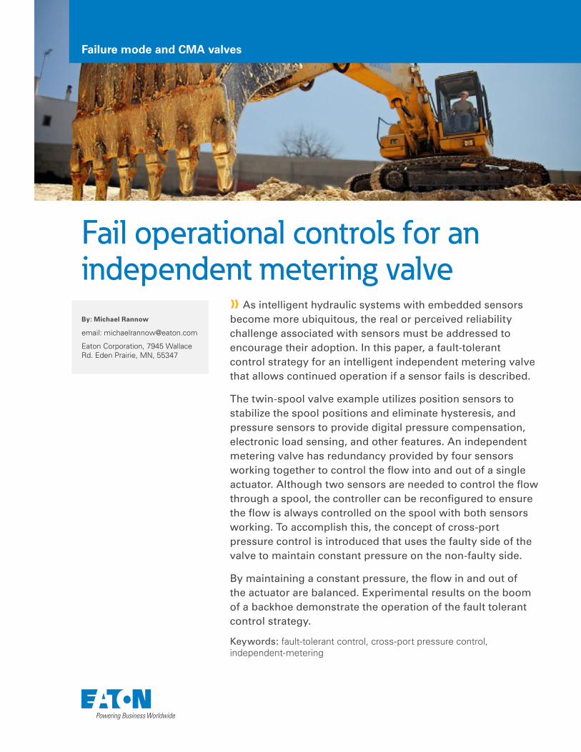
The Eaton CMA™ valve, is an example of an intelligent hydraulic valve that relies on sensor feedback for operation. It is a two-stage independent metering valve with a position sensor and a pressure sensor for each control spool. The closed-loop control of the spool position enables fast performance and zero hysteresis, but it also creates a reliance on the position sensor for operation. Pressure sensor feedback is used to enable features such as digital pressure compensation, load direction detection, back pressure control, and electronic load sense, among others. In typical operation, all four sensors are used to make the valve function. However, there is a redundancy that exists when the two spools are being used to control two sides of the same actuator. Since there is a relationship between valve position, pressure drop, and flow, and there is a known relationship between the flow in and the flow out of an actuator, only three of the four sensors are needed to have complete information about the state of the valve. Thus, while purely redundant sensors are often cost prohibitive, the redundancy provided by knowledge of an actuator area ratio can be utilized to develop fail operational controllers.
Eaton CMA Independent Metering Valve
5 Detecting and diagnosing a faulty sensor is a critical component of creating fault tolerant systems. There are many methods for detecting faults in a system, some of which, such as sensor out-of-range detection, can immediately identify a faulty sensor. In other methods, such as poor demand tracking or a mismatch between the estimated flow in and out of an actuator, they can detect a fault somewhere in this system, but cannot determine the root cause without additional tests. For the purposes of this paper, it is assumed that a sensor fault has been detected and correctly identified. Once a fault has been identified, reconfigured control modes can allow the valve to operate with any one of the four sensors failed. In the next section, the structure and operation of the controller for a fault in any of the four sensors is described.
2
CMA Independent Metering Valve
3
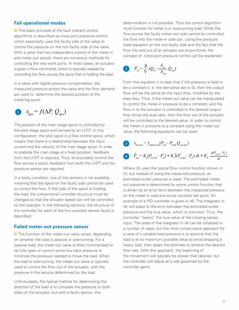
Fail operational modes
5 The basic principle of the fault tolerant control algorithms is described as cross-port pressure control, which essentially uses the faulty side of the valve to control the pressure on the non-faulty side of the valve. With a valve that has independent control of the meter-in and meter-out spools, there are numerous methods for controlling the two work ports. In most cases, an actuator is given a flow command, which is typically realized by controlling the flow across the spool that is holding the load.
In a valve with digital pressure compensation, the measured pressure across the valve and the flow demand are used to determine the desired position of the metering spool:
xdes = ƒ(∆P, Qdes)1
The position of the main stage spool is controlled by the pilot stage spool and sensed by an LVDT. In this configuration, the pilot spool is a flow control spool, which means that there is a relationship between the input current and the velocity of the main stage spool. In order to stabilize the main stage at a fixed position, feedback from the LVDT is required. Thus, to accurately control the flow across a spool, feedback from both the LVDT and the pressure sensor are required.
In a faulty condition, one of the sensors is not available, meaning that the spool on the faulty side cannot be used to control the flow. If that side of the spool is holding the load, the conventional controller structure must be changed so that the actuator speed can still be controlled by the operator. In the following sections, the structure of the controller for each of the four possible sensor faults is described.
Failed meter-out pressure sensor
5 The function of the meter-out valve varies, depending on whether the load is passive or overrunning. For a passive load, the meter-out valve is often commanded to be fully open or control some low back pressure to minimize the pressure needed to move the load. When the load is overrunning, the meter-out valve is typically used to control the flow out of the actuator, with the pressure in the service determined by the load.
Unfortunately, the typical method for determining the direction of the load is to compare the pressure on both sides of the actuator, but with a faulty sensor, this
determination is not possible. Thus the control algorithm must function for either a or overrunning load. While the flow across the faulty meter-out side cannot be controlled, the flow into the meter-in side can. Using the pressure state equation on the non-faulty side and the fact that the flow into and out of an actuator are proportional, the concept of cross-port pressure control can be explained:
Aout
Ain2
From this equation it is clear that if the pressure is held to be a constant (i. e. the derivative set to 0), then the output flow will be the same as the input flow, modified by the area ratio. Thus, if the meter-out valve can be manipulated to control the meter-in pressure to be a constant, and the flow in to the actuator is controlled to the desired output flow times the area ratio, then the flow out of the actuator will be controlled to the desired value. In order to control the meter-in pressure to a constant using the meter-out valve, the following equations can be used:
d(Pin,des– Pin)
dt
~
3
4
Where (3) uses the typical flow control function shown in (1), but instead of using the measured pressure, an estimated outlet pressure is used. The estimated meter-out pressure is determined by some control function that is driven by an error term between the measured pressure on the meter-in side and some constant set point. An example of a PID controller is given in (4). The integrator in (4) will adapt to the error between the estimated outlet pressure and the true value, which is unknown. Thus, the controller “learns” the true value of the missing sensor input. The state of the integrator in (4) can be initialized in a number of ways, but the most conservative approach for a case of a variable load pressure is to assume that the load is at its maximum possible value to avoid dropping a heavy load, then adapt the estimate to achieve the desired flow rate. With this approach, the beginning of the movement will typically be slower than desired, but the controller will adjust at a rate governed by the controller gains.
This controller will work for both a passive and an overrunning load. For an overrunning load, the cross-port pressure control will work as described, the meter-out valve will start by assuming a heavy load and then adapt until the meter-in pressure is held to be a constant. With a passive load, the meter-in pressure will be determined by the load pressure, which will likely be higher than the desired pressure set point. In this condition, the meter-out valve will not be able to control the meter-in pressure down to the desired value, but it will try to do so anyway. The consequence of a meter-in pressure that is too high is that the meter-out valve will try to open more to lower the pressure. Thus, the meter-out valve will open until it is completely out of the way, which is typically the desired condition for a passive load.
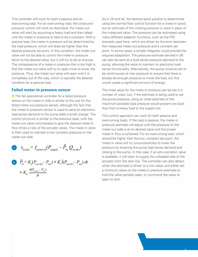
Failed meter-in pressure sensor
5 The fail-operational controller for a failed pressure sensor on the meter-in side is similar to the one for the failed meter-out pressure sensor, although the fact that the meter-in pressure sensor is used to send an electronic load sense demand to the pump adds a small change. The control structure is similar to the previous case, with the meter-out valve commanded to give the desired meter-in flow times a ratio of the actuator areas. The meter-in valve is then used to maintain a low constant pressure on the meter-out side.
xin,des = ƒmeter-in(Psupply – Pin, Qin,des)~
5
6d(Pout,des– Pout)
dt
~
d(Pout,des– Pout)
dt
~
As in (3) and (4), the desired spool position is determined using the normal flow control function for a meter-in spool, but an estimate of the missing pressure is used in place of the measured value. The pressure can be estimated using many different adaption functions, such as the PID example used here, which are driven by the error between the measured meter-out pressure and a constant set point. In some cases, a simple integrator could provide the required adaptation. The pressure estimate derived in (6) can also be sent as a load sense pressure demand to the pump, allowing the valve to maintain its electronic load sense functionality. Alternatively, the pump could be set to be continuously at max pressure to ensure that there is always be enough pressure to move the load, but this would waste a significant amount of energy.
The initial value for the meter-in pressure can be set in a number of ways, but, if the estimate is being used to set the pump pressure, using an initial estimate of the maximum possible load pressure would prevent any back flow from a heavy load to the supply line.
This control approach can work for both passive and overrunning loads. If the load is passive, the meter-in pressure estimate will adjust until the pressure on the meter-out side is at its desired value and the proper meter-in flow is achieved. For an overrunning load, which should be higher than the low, constant set point, the meter-in valve will try (unsuccessfully) to lower the pressure by lowering the pump load sense demand and closing to the pump. In this case, if an anti-cavitation valve is available, it will open to supply the unloaded side of the actuator from the tank line. The controller can also detect when the estimate is driven to a low value, and either set a minimum value on the meter-in pressure estimate to hold the valve partially open, or command the valve to open to tank.
4
Failed meter-out position sensor
5 For a failed position sensor, the challenges of not being able to detect a passive/overrunning load and not knowing how to set the pump pressure are alleviated because the pressure sensors are still functioning. However, the fact that there is no steady-state relationship between the input current and the spool position presents a significant challenge. For the CMA valve, the current into the pilot stage is related to the flow out of the pilot stage. This gives a relationship between the input current and the mainstage velocity, meaning that the control input (current) is one integrator removed from the desired output (spool position). This forces the controller to be less aggressive and much more damped than the position controller on a non-faulty valve. The cross-port pressure control can again be used for a failed position controller, but rather than the error term being used to determine the desired position, the difference between the meter-out pressure and a desired set point is used to determine the current sent to the meter-in pilot spool:
d(Pin,des– Pin)
dt
7
In this example, the function is a mapping from the input current to the spool velocity which removes some of the nonlinearity in the system. For a CMA valve, a training routine is used to learn the relationship between the current and velocity to remove nonlinearity and part-to-part variation from the controller, but this could also be
generated from a known model of the system. In addition to the PID terms, a feedforward term is added based on the desired spool velocity which improves the response when starting or adjusting a command. A damping function, g, based on the two pressures is also added to help damp out oscillations.
As in the failed pressure case, the control tries to drive the meter-in pressure to a constant value. As seen in (2), if the pressure is a constant, then the flow in and flow out of the actuator are matched. Thus, if the meter-in flow is controlled and the meter-in pressure is constant, then the meter-in flow is also controlled to the correct value.
Controlling the flow out of an actuator with an overrunning load without position feedback is the most challenging condition, since any error or instability in the spool movement can result in a falling load. For a passive load, the same controller can be used; the meter-in pressure will likely be higher than the constant set point, which will drive the meter-out spool fully open and out of the way. This is the desired behavior in a passive condition. In this case, the integrator in (7) must be disabled to avoid integrator wind-up.
5
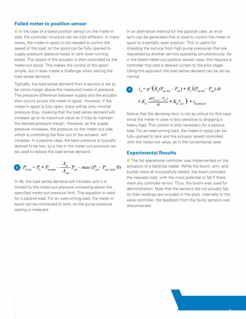
Failed meter-in position sensor
5 In the case of a failed position sensor on the meter-in side, the controller structure can be a bit different. In many cases, the meter-in spool is not needed to control the speed of the load, so the spool can be fully opened to supply pressure (passive loads) or tank (over-running loads). The speed of the actuator is then controlled by the meter-out spool. This makes the control of the spool simple, but it does create a challenge when setting the load sense demand.
Typically, the load sense demand from a service is set to be some margin above the measured meter-in pressure. The pressure difference between supply and the actuator then occurs across the meter-in spool. However, if the meter-in spool is fully open, there will be only minimal pressure drop, meaning that the load sense demand will increase up to its maximum value as it tries to maintain the desired pressure margin. However, as the supply pressure increases, the pressure on the meter-out side, which is controlling the flow out of the actuator, will increase. In a passive case, the back pressure is typically desired to be low, so a rise in the meter-out pressure can be used to reduce the load sense demand:
In (8), the load sense demand will increase until it is limited by the meter-out pressure increasing above the specified meter-out pressure limit. This equation is used for a passive load. For an overrunning load, the meter-in spool can be connected to tank, so the pump pressure setting is irrelevant.
In an alternative method for the passive case, an error term can be generated that is used to control the meter-in spool to a partially open position. This is useful for shielding the service from high pump pressures that are requested by another service operating simultaneously. As in the failed meter-out position sensor case, this requires a controller that sets a desired current to the pilot stage. Using this approach the load sense demand can be set as normal.
Notice that the damping term is not as critical for this case since the meter-in case is less sensitive to dropping a heavy load. This control is only necessary for a passive load. For an overrunning load, the meter-in spool can be fully opened to tank and the actuator speed controlled with the meter-out valve, as in the conventional case.
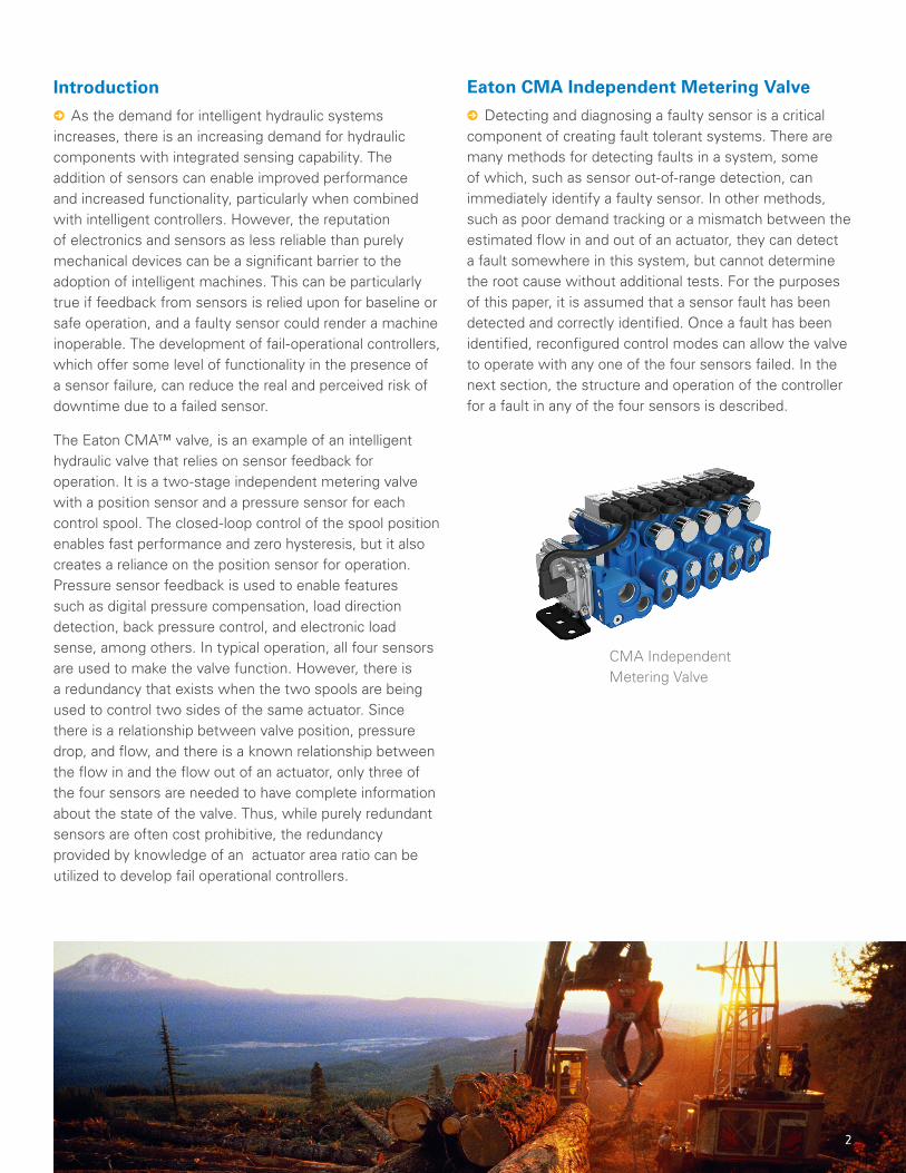
Experimental Results
5 The fail operational controller was implemented on the actuators of a backhoe loader. While the boom, arm, and bucket were all successfully tested, the boom provided the heaviest load, with the most potential to fall if there were any controller errors. Thus, the boom was used for demonstration. Note that the sensors did not actually fail, so their readings are included in the plots. Internally to the valve controller, the feedback from the faulty sensors was disconnected.
Pls,des = Pls + Pmargin – —— Pout – max (Pout– Pout, limit, 0)Aout
Ain8
9d(Pout,des– P
dt
d(Pout,des– Pout)
dt
6
7
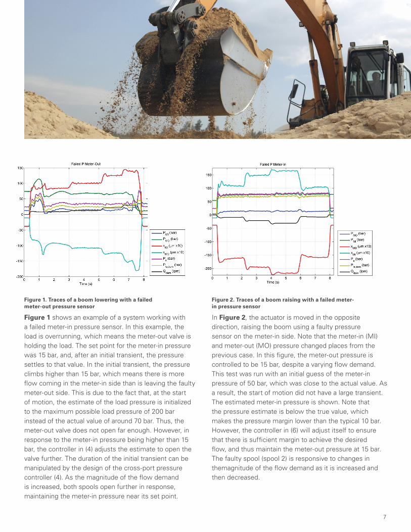
Figure 1. Traces of a boom lowering with a failed meter-out pressure sensor
Figure 2. Traces of a boom raising with a failed meter-in pressure sensor
Figure 1 shows an example of a system working with a failed meter-in pressure sensor. In this example, the load is overrunning, which means the meter-out valve is holding the load. The set point for the meter-in pressure was 15 bar, and, after an initial transient, the pressure settles to that value. In the initial transient, the pressure climbs higher than 15 bar, which means there is more flow coming in the meter-in side than is leaving the faulty meter-out side. This is due to the fact that, at the start of motion, the estimate of the load pressure is initialized to the maximum possible load pressure of 200 bar instead of the actual value of around 70 bar. Thus, the meter-out valve does not open far enough. However, in response to the meter-in pressure being higher than 15 bar, the controller in (4) adjusts the estimate to open the valve further. The duration of the initial transient can be manipulated by the design of the cross-port pressure controller (4). As the magnitude of the flow demand is increased, both spools open further in response, maintaining the meter-in pressure near its set point.
In Figure 2, the actuator is moved in the opposite direction, raising the boom using a faulty pressure sensor on the meter-in side. Note that the meter-in (MI) and meter-out (MO) pressure changed places from the previous case. In this figure, the meter-out pressure is controlled to be 15 bar, despite a varying flow demand. This test was run with an initial guess of the meter-in pressure of 50 bar, which was close to the actual value. As a result, the start of motion did not have a large transient. The estimated meter-in pressure is shown. Note that the pressure estimate is below the true value, which makes the pressure margin lower than the typical 10 bar. However, the controller in (6) will adjust itself to ensure that there is sufficient margin to achieve the desired flow, and thus maintain the meter-out pressure at 15 bar. The faulty spool (spool 2) is responsive to changes in themagnitude of the flow demand as it is increased and then decreased.
8
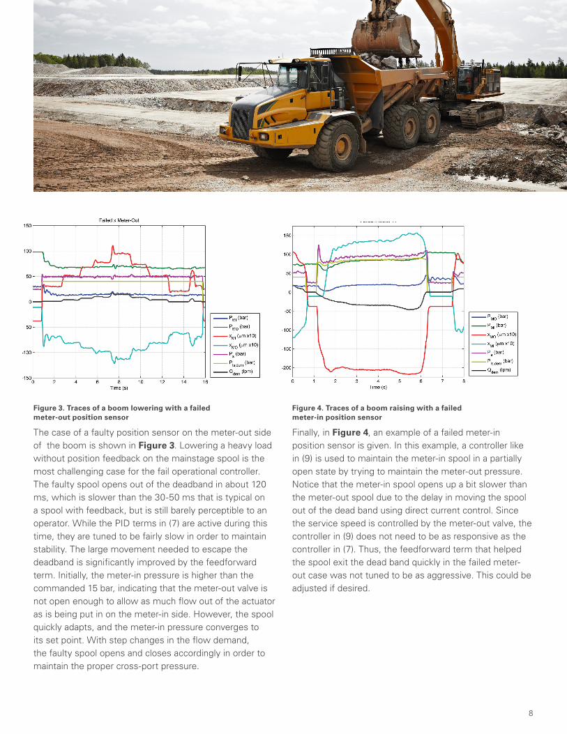
Figure 3. Traces of a boom lowering with a failed meter-out position sensor
Figure 4. Traces of a boom raising with a failed meter-in position sensor
The case of a faulty position sensor on the meter-out side of the boom is shown in Figure 3. Lowering a heavy load without position feedback on the mainstage spool is the most challenging case for the fail operational controller. The faulty spool opens out of the deadband in about 120 ms, which is slower than the 30-50 ms that is typical on a spool with feedback, but is still barely perceptible to an operator. While the PID terms in (7) are active during this time, they are tuned to be fairly slow in order to maintain stability. The large movement needed to escape the deadband is significantly improved by the feedforward term. Initially, the meter-in pressure is higher than the commanded 15 bar, indicating that the meter-out valve is not open enough to allow as much flow out of the actuator as is being put in on the meter-in side. However, the spool quickly adapts, and the meter-in pressure converges to its set point. With step changes in the flow demand, the faulty spool opens and closes accordingly in order to maintain the proper cross-port pressure.
Finally, in Figure 4, an example of a failed meter-in position sensor is given. In this example, a controller like in (9) is used to maintain the meter-in spool in a partially open state by trying to maintain the meter-out pressure. Notice that the meter-in spool opens up a bit slower than the meter-out spool due to the delay in moving the spool out of the dead band using direct current control. Since the service speed is controlled by the meter-out valve, the controller in (9) does not need to be as responsive as the controller in (7). Thus, the feedforward term that helped the spool exit the dead band quickly in the failed meter-out case was not tuned to be as aggressive. This could be adjusted if desired.
Conclusion
5 In this paper, a method for utilizing the inherent information redundancy in an independent metering valve with position and pressure sensors to create a fault tolerant system was described. While a working position and pressure sensor are needed to accurately control the flow across a spool that uses electronic pressure compensation, the controller can always be re-structured so that the flow is controlled on the spool with two working sensors, with the other spool attempting to
regulate the pressure on the non-faulty side of the work port to a constant value. Maintaining a constant pressure ensures a balance between the flow in and out of the actuator. Experimental results demonstrate that this approach can be tailored to a failure in any one of the four sensors on the valve. This creates a valve that is tolerant to sensor faults, which improves the reliability and uptime for the system.
EatonHydraulics Group Asia PacificEaton Building4th Floor, No. 3 Lane 280 Linhong Rd.Changning DistrictShanghai 200335ChinaTel: (+86 21) 5200 0099Fax: (+86 21) 5200 0400
EatonHydraulics Group EuropeRoute de la Longeraie 71110 MorgesSwitzerlandTel: +41 (0) 21 811 4600Fax: +41 (0) 21 811 4601
EatonHydraulics Group USA14615 Lone Oak RoadEden Prairie, MN 55344USATel: 952-937-9800Fax: 952-294-7722www.eaton.com/hydraulics
© 2017 Eaton All Rights Reserved Eaton is a registered trademark.
All other trademarks are property of their respective owners.
Follow us on social media to get the latest product and support information.
Get started todayTo learn more about failure operational topics, visit eaton.com/DMC
5
Nomenclature
Pressure difference: Psupply – Pin or Pout – Ptank on in or out side
Pressure, Pressure on input side, Pressure on output side
Desired spool position, position on input side, position on output side
Desired flow rate – note any variable with a _des is a desired value
Function describing relationship between pres sure, flow, and position
Bulk modulus of the fluid
Volume of the fluid
Actuator Area on the input side, actuator Area on the output side
Estimated pressure on the inlet side, estimated pressure on outlet side
Proportional, Integral, Defivative, and Feed forward controller gains
Current sent to the pilot spool actuator in the input and output side
Inverse of a function that relates the input current to the spool velocity
Damping function that uses actuator pressures to smooth the control
Current needed to move the pilot spool to the edge of its deadband
Desired load sense pressure (desired supply pressure minus margin)
Pressure margin between Pls and supply pressure
∆P
Pin , Pout
xin , xout
xdes
Qdes
ƒ( )
Ain , Aout
Pin , Pout
Kp , Ki , Kd , Kff
iin , iout
ideadband
Pls, des
Pmargin
~ ~