Embed Size (px)
Citation preview
1
Failure Analysis of a Reinforced Concrete Silo
T. Ebisch, M.S., P.E.1 and R. Chancey, Ph.D., P.E.2
1Nelson Forensics, 2740 Dallas Parkway, Suite 220, Plano, Texas, 75093; Ph (469) 429-9000; email: [email protected] 2Nelson Forensics, 2740 Dallas Parkway, Suite 220, Plano, Texas, 75093; Ph (469) 429-9000; email: [email protected]
ABSTRACT
Silos are most often constructed of steel panels or reinforced concrete; and are typically used to store bulk solids such as food, fuel, and feed for livestock. Because the stored bulk material is flowable, silos are subjected to complex load scenarios requiring unique design considerations. In the spring of 2013, a recently constructed reinforced concrete silo storing solid biomass material suffered a catastrophic failure resulting in displacement of the stored material and complete loss of the structure's use until it was repaired. Additionally, multiple neighboring silos, which were of comparable construction and design, manifested similar distress patterns to those observed at the subject silo just prior to its failure. The objective of this paper is to explain the investigative methodology and conclusions drawn regarding the failure mode of the subject silo. The investigation revealed that the failure initiated at a concrete keyway cast into the silo wall at the silo's elevated concrete floor; and that the failure was caused by construction defects.
INTRODUCTION
Summary of Failure During the spring of 2013, a recently constructed reinforced concrete silo storing solid biomass material suffered a catastrophic failure resulting in displacement of the stored material and complete loss of the structure's use until it was repaired. The subject silo was one of four similar silos constructed as part of an addition to a nearby industrial facility. All four silos exhibited patterns of distress similar to what existed at exterior face of the failed silo walls prior to the failure of the subject silo. The subject silo was not designed in accordance with best engineering practices at the time, and the silo was not constructed in accordance with the design documents.
This paper was published at the Forensic Engineering 8th Congress, held November 29-December 2, 2018 in Austin, TX. The published version of this paper is available for purchase and download at:
https://ascelibrary.org/doi/book/10.1061/9780784482018
2
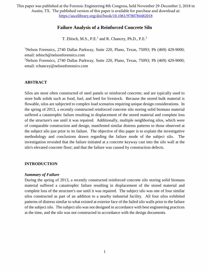
Silo Structure The subject structure was a reinforced concrete silo measuring 50' in diameter and 80' in height. The silo was designed to store wood biomass material used in the adjacent industrial facility. The silo was centrally filled through its roof by an exterior elevator, and centrally emptied by a mechanical auger at the base. An elevated reinforced concrete slab separated the material storage area from a mechanical room at the base of the silo. The top surface of the elevated concrete slab was located 12' above the base elevation of the silo. Figure 1 depicts the general configuration of the subject silo.
Figure 1. Section view of the silo configuration
3
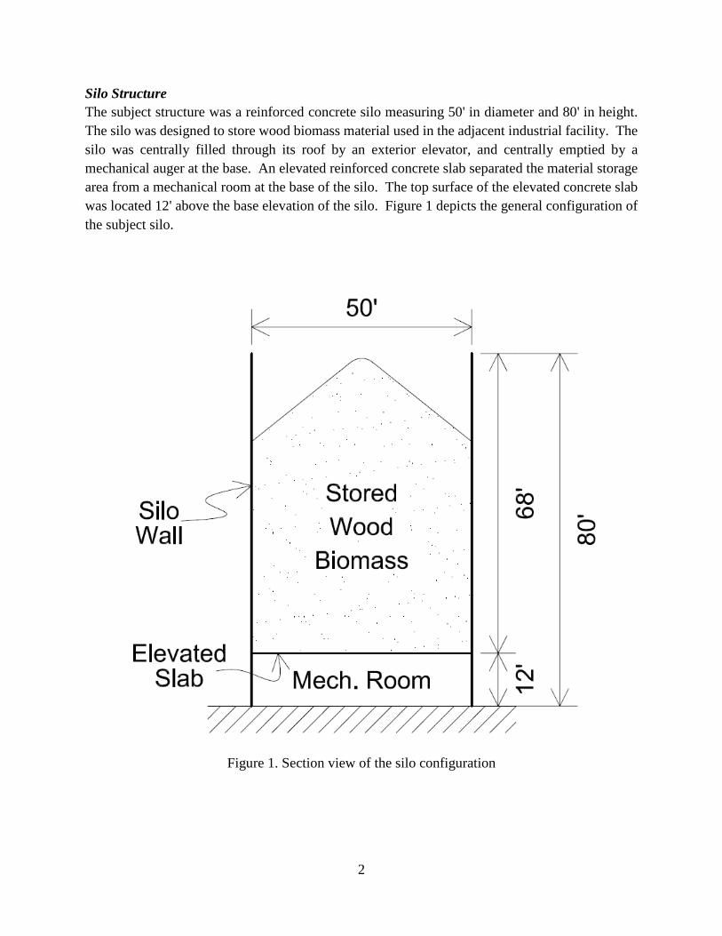
The reinforced silo wall was designed to be constructed in 20 4' vertical lifts (jumps) using climbing formwork (jump forms) with 3 jumps below the elevated slab and 17 jumps above. The circumferential reinforcement, or hoop steel, within each jump varied throughout the height of the silo, with more hoops being specified in locations with greater anticipated loading (from lateral pressures). Figure 2 presents a conceptual layout of the hoop steel reinforcing in each jump.
Figure 2. Conceptual section view of the hoop steel reinforcing layout
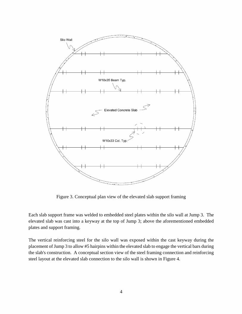
The vertical steel reinforcing members were specified as #4 bars spaced at 1' on-center around the perimeter of the silo. At wall openings, the vertical steel was to be increased on either side of the opening in between the normal vertical steel members. The elevated concrete slab was 15-1/2" thick, and was reinforced with a top and bottom mat of reinforcing steel. Each mat was comprised of #6 steel bars spaced at 6" on-center in the east/west direction, and 10" on-center in the north/south direction. The slab was to be supported by steel frames comprised of wide-flange steel members, as shown in Figure 3.
4
Figure 3. Conceptual plan view of the elevated slab support framing
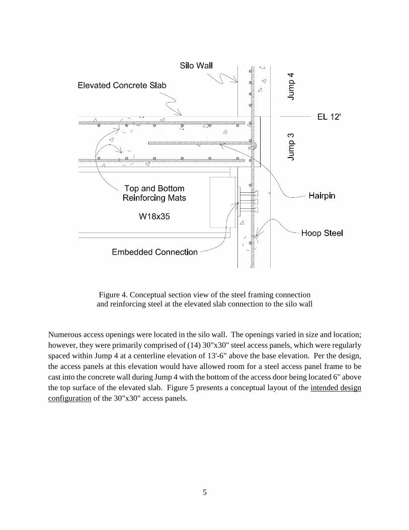
Each slab support frame was welded to embedded steel plates within the silo wall at Jump 3. The elevated slab was cast into a keyway at the top of Jump 3; above the aforementioned embedded plates and support framing. The vertical reinforcing steel for the silo wall was exposed within the cast keyway during the placement of Jump 3 to allow #5 hairpins within the elevated slab to engage the vertical bars during the slab's construction. A conceptual section view of the steel framing connection and reinforcing steel layout at the elevated slab connection to the silo wall is shown in Figure 4.
5
Figure 4. Conceptual section view of the steel framing connection
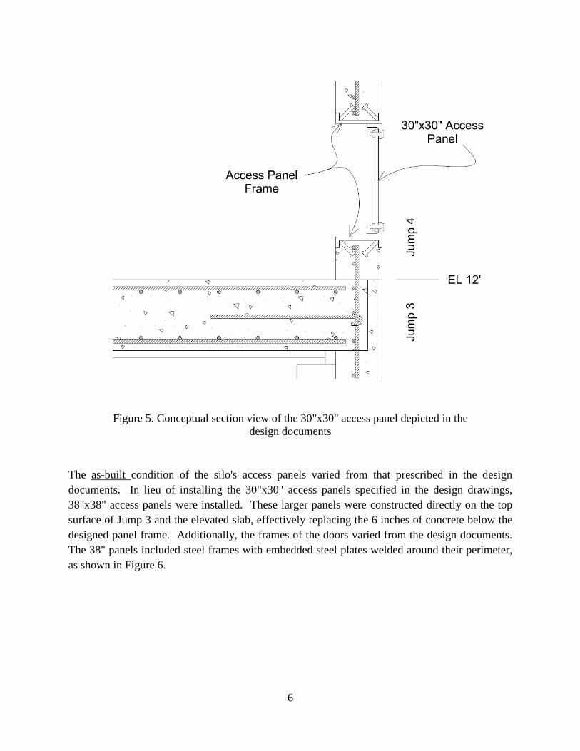
and reinforcing steel at the elevated slab connection to the silo wall Numerous access openings were located in the silo wall. The openings varied in size and location; however, they were primarily comprised of (14) 30"x30" steel access panels, which were regularly spaced within Jump 4 at a centerline elevation of 13'-6" above the base elevation. Per the design, the access panels at this elevation would have allowed room for a steel access panel frame to be cast into the concrete wall during Jump 4 with the bottom of the access door being located 6" above the top surface of the elevated slab. Figure 5 presents a conceptual layout of the intended design configuration of the 30"x30" access panels.
6
Figure 5. Conceptual section view of the 30"x30" access panel depicted in the
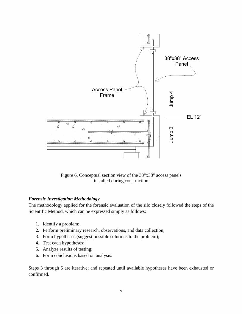
design documents The as-built condition of the silo's access panels varied from that prescribed in the design documents. In lieu of installing the 30"x30" access panels specified in the design drawings, 38"x38" access panels were installed. These larger panels were constructed directly on the top surface of Jump 3 and the elevated slab, effectively replacing the 6 inches of concrete below the designed panel frame. Additionally, the frames of the doors varied from the design documents. The 38" panels included steel frames with embedded steel plates welded around their perimeter, as shown in Figure 6.
7
Figure 6. Conceptual section view of the 38"x38" access panels
installed during construction Forensic Investigation Methodology The methodology applied for the forensic evaluation of the silo closely followed the steps of the Scientific Method, which can be expressed simply as follows:
1. Identify a problem; 2. Perform preliminary research, observations, and data collection; 3. Form hypotheses (suggest possible solutions to the problem); 4. Test each hypotheses; 5. Analyze results of testing; 6. Form conclusions based on analysis.
Steps 3 through 5 are iterative; and repeated until available hypotheses have been exhausted or confirmed.
8
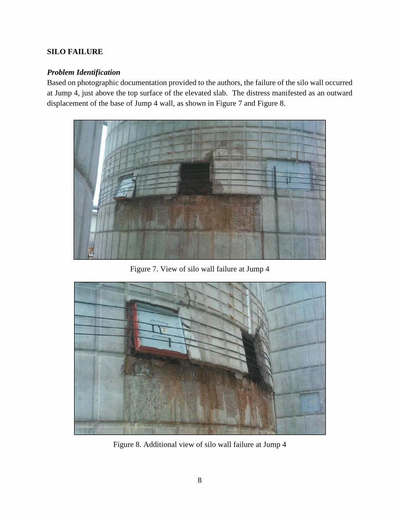
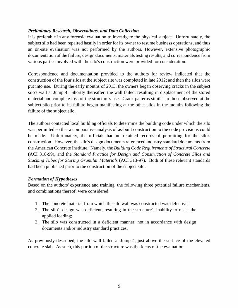
SILO FAILURE Problem Identification Based on photographic documentation provided to the authors, the failure of the silo wall occurred at Jump 4, just above the top surface of the elevated slab. The distress manifested as an outward displacement of the base of Jump 4 wall, as shown in Figure 7 and Figure 8.
Figure 7. View of silo wall failure at Jump 4
Figure 8. Additional view of silo wall failure at Jump 4
9
Preliminary Research, Observations, and Data Collection It is preferable in any forensic evaluation to investigate the physical subject. Unfortunately, the subject silo had been repaired hastily in order for its owner to resume business operations, and thus an on-site evaluation was not performed by the authors. However, extensive photographic documentation of the failure, design documents, materials testing results, and correspondence from various parties involved with the silo's construction were provided for consideration. Correspondence and documentation provided to the authors for review indicated that the construction of the four silos at the subject site was completed in late 2012; and then the silos were put into use. During the early months of 2013, the owners began observing cracks in the subject silo's wall at Jump 4. Shortly thereafter, the wall failed, resulting in displacement of the stored material and complete loss of the structure's use. Crack patterns similar to those observed at the subject silo prior to its failure began manifesting at the other silos in the months following the failure of the subject silo. The authors contacted local building officials to determine the building code under which the silo was permitted so that a comparative analysis of as-built construction to the code provisions could be made. Unfortunately, the officials had no retained records of permitting for the silo's construction. However, the silo's design documents referenced industry standard documents from the American Concrete Institute. Namely, the Building Code Requirements of Structural Concrete (ACI 318-99), and the Standard Practice for Design and Construction of Concrete Silos and Stacking Tubes for Storing Granular Materials (ACI 313-97). Both of these relevant standards had been published prior to the construction of the subject silo. Formation of Hypotheses Based on the authors' experience and training, the following three potential failure mechanisms, and combinations thereof, were considered:
1. The concrete material from which the silo wall was constructed was defective; 2. The silo's design was deficient, resulting in the structure's inability to resist the
applied loading; 3. The silo was constructed in a deficient manner, not in accordance with design
documents and/or industry standard practices. As previously described, the silo wall failed at Jump 4, just above the surface of the elevated concrete slab. As such, this portion of the structure was the focus of the evaluation.
10
Testing of Hypotheses Hypothesis #1: Defective Concrete Materials To determine if a defect was present in the concrete used for construction of the silo wall, the authors reviewed the construction drawings, both aforementioned ACI documents, and materials testing reports from the compressive strength test cylinders obtained during construction of the silo. ACI 313-97 specifies that the minimum 28-day concrete compressive strength (f'c) shall not be less than 4000 psi; and the design drawings specify a minimum f'c of 5000 psi. The concrete cylinder compressive strength test results for the subject silo revealed that, on average, the test cylinders reached an f'c of approximately 5600 psi. These data indicate that defective concrete material was an unlikely cause of the silo failure, and thus Hypothesis #1 was excluded from further consideration. Hypothesis #2: Design Deficiency To determine if a deficiency was inherent in the subject silo's design, the authors performed a comparative analysis of provisions from applicable industry standards with the silo configuration set forth within the design documents. The purpose of this analysis was to determine if the silo's design would have failed under normal use. Silo walls must withstand outward pressure imparted by the material stored within. To accomplish this, the shell/wall reinforcement must be sufficient to confine this outward pressure. This is not only accomplished by the providing the proper quantity/amount of reinforcing steel, but also by placing the hoop reinforcing outside of the vertical reinforcing. This orientation allows the tensile forces that develop within the vertical reinforcement to transfer into the confining hoop reinforcement. The importance of this detail for reinforced silo walls, like those at the subject silo, is reflected in ACI 313-97, which states in Section 4.3 Details and placement of reinforcement sub-section 3.2.12:
In singly-reinforced circular walls, the main hoop reinforcement shall be placed nearer the outer face.
According to the design drawings, the hoop reinforcing was intended to be located inside of the vertical, reinforcement in direct conflict with the intent of ACI 313-97, see Figure 4 through Figure 6. While this deficiency was present in the design, numerical analysis was still necessary to determine if the as-designed silo wall would have failed under normal use if properly constructed. To accomplish this, multiple wall locations within Jump 4 were evaluated based loading conditions at the time of failure. Specifically, the silo wall was evaluated as if it was completely full; and using materials properties for the stored material from a lab testing report provided by the owner.
11
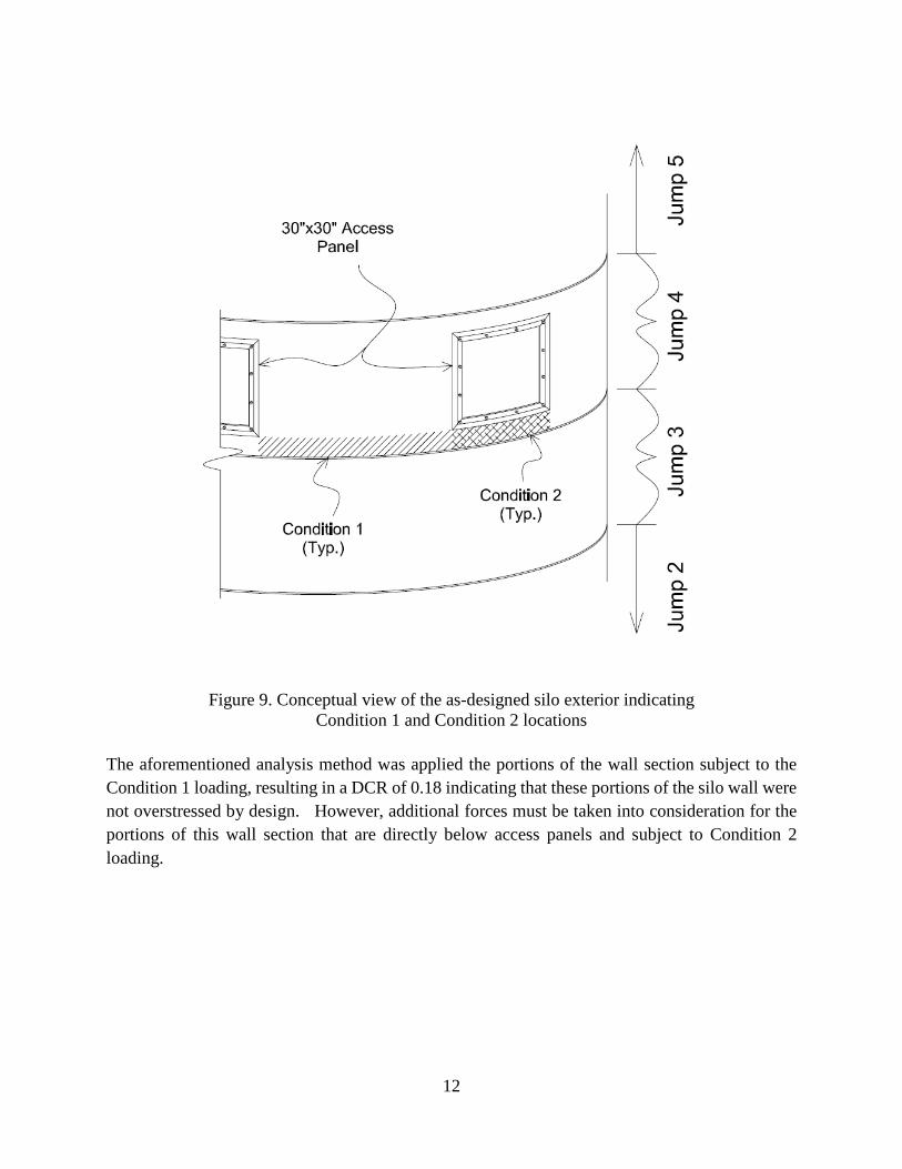
To determine the design loads, ACI 313-97 utilizes Janssen's method for determining horizontal and vertical pressures on silo walls. This method begins by first determining the initial vertical pressure at a specified depth below the surface of the stored material. This vertical pressure is then mathematically converted into a horizontal pressure by multiplying it by a lateral pressure ratio derived from the stored material's angle of internal friction. This converted horizontal pressure is then multiplied by a minimum overpressure (safety) factor of 1.5 to attain the horizontal design pressure. Using the foregoing, the authors calculated the design pressures for each elevation of interest below the surface of the stored material at Jump 4. The first location of interest was at the hoop reinforcing above the Jump 4 access panels. This location was chosen based on the authors' review of the failure photographs, which indicated that the portion of the wall above the access panels did not fail. To analyze the reinforcing in this location, the authors compared the calculated horizontal design pressure to the calculated capacity of the silo wall by dividing the two values to attain a demand capacity ratio (DCR). Whereby a DCR value less than or equal to 1 is acceptable, and a value greater than 1 is unacceptable and indicates that the silo wall is overstressed by the horizontal design pressures. In determining the capacity of the silo wall above the access panels, the authors applied the calculated horizontal design pressure at the top of the panels to a 1' vertical section of silo wall. This was accomplished by converting the horizontal design pressure into the tensile force applied to the hoop reinforcing. Comparing the tension applied to the hoop reinforcing from the design pressure to the calculated capacity of the hoop reinforcing within the 1' vertical wall section resulted in a DCR of approximately 0.2 indicating that the wall section above the panels was not overstressed by design. The second location of interest was at the hoop reinforcing in the wall section below the bottom elevation of the access panels and above Jump 3. Two load conditions (Condition 1 and Condition 2) are present at this location section of the silo wall. Condition 1 exists at the wall sections located between access panels, and Condition 2 is present directly below the panels, as shown in Figure 9.
12
Figure 9. Conceptual view of the as-designed silo exterior indicating
Condition 1 and Condition 2 locations The aforementioned analysis method was applied the portions of the wall section subject to the Condition 1 loading, resulting in a DCR of 0.18 indicating that these portions of the silo wall were not overstressed by design. However, additional forces must be taken into consideration for the portions of this wall section that are directly below access panels and subject to Condition 2 loading.
13
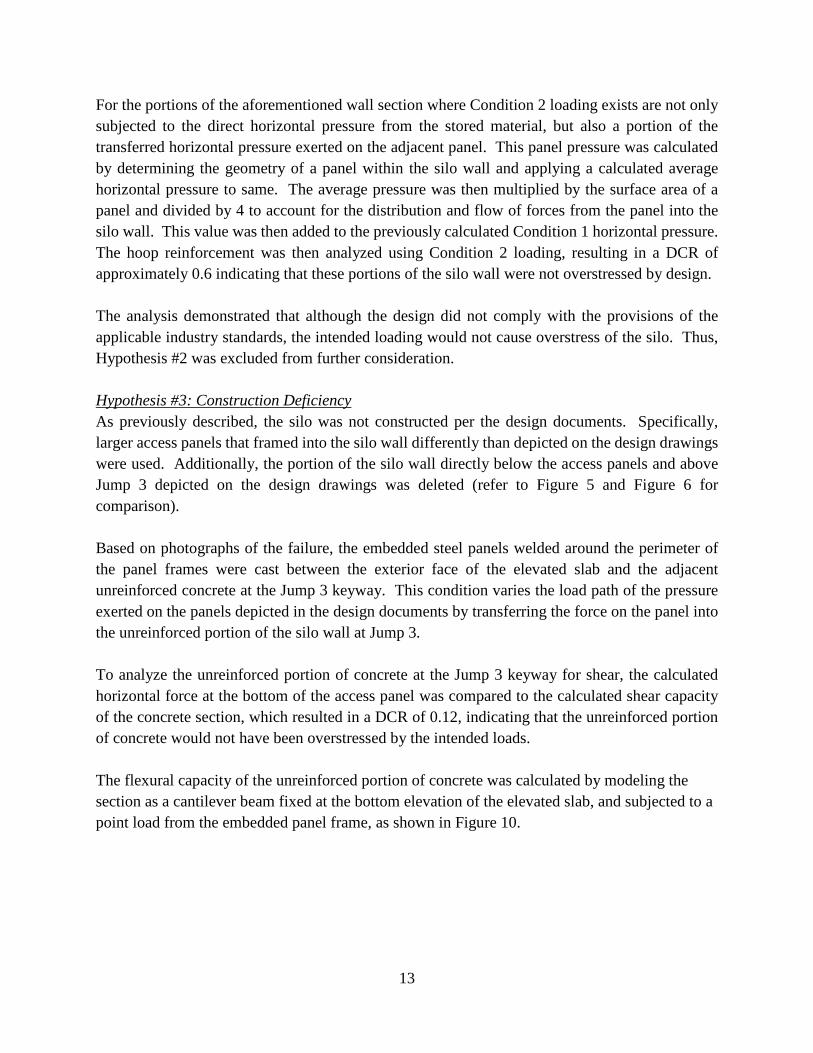
For the portions of the aforementioned wall section where Condition 2 loading exists are not only subjected to the direct horizontal pressure from the stored material, but also a portion of the transferred horizontal pressure exerted on the adjacent panel. This panel pressure was calculated by determining the geometry of a panel within the silo wall and applying a calculated average horizontal pressure to same. The average pressure was then multiplied by the surface area of a panel and divided by 4 to account for the distribution and flow of forces from the panel into the silo wall. This value was then added to the previously calculated Condition 1 horizontal pressure. The hoop reinforcement was then analyzed using Condition 2 loading, resulting in a DCR of approximately 0.6 indicating that these portions of the silo wall were not overstressed by design. The analysis demonstrated that although the design did not comply with the provisions of the applicable industry standards, the intended loading would not cause overstress of the silo. Thus, Hypothesis #2 was excluded from further consideration. Hypothesis #3: Construction Deficiency As previously described, the silo was not constructed per the design documents. Specifically, larger access panels that framed into the silo wall differently than depicted on the design drawings were used. Additionally, the portion of the silo wall directly below the access panels and above Jump 3 depicted on the design drawings was deleted (refer to Figure 5 and Figure 6 for comparison). Based on photographs of the failure, the embedded steel panels welded around the perimeter of the panel frames were cast between the exterior face of the elevated slab and the adjacent unreinforced concrete at the Jump 3 keyway. This condition varies the load path of the pressure exerted on the panels depicted in the design documents by transferring the force on the panel into the unreinforced portion of the silo wall at Jump 3. To analyze the unreinforced portion of concrete at the Jump 3 keyway for shear, the calculated horizontal force at the bottom of the access panel was compared to the calculated shear capacity of the concrete section, which resulted in a DCR of 0.12, indicating that the unreinforced portion of concrete would not have been overstressed by the intended loads. The flexural capacity of the unreinforced portion of concrete was calculated by modeling the section as a cantilever beam fixed at the bottom elevation of the elevated slab, and subjected to a point load from the embedded panel frame, as shown in Figure 10.
14
Figure 10. Conceptual illustration of flexural model
The foregoing calculation resulted in a DCR of 1.17 indicating that the unreinforced portion of concrete at the Jump 3 keyway directly below the access panels was overstressed by the load from the panel frame. A similar analysis was conducted for the portions of the silo wall that were located between the access panels at Jump 4. The shear and flexural capacities were calculated in a similar fashion as before, taking into account the shear capacity of the vertical reinforcing steel and the geometry differences between an access panel and the portion of silo wall between the panels. The shear DCR values for the concrete and vertical reinforcing steel were 0.35 and 0.14, respectively; indicating that neither was overstressed due to shear. However, the calculated flexural DCR value for the unreinforced portion of concrete at the Jump 3 keyway was 1.63 indicating that the concrete was overstressed.
15
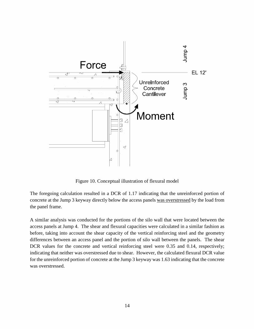
Step 5. Analysis The testing of Hypothesis #1 revealed that the concrete used for construction of the silo wall met the compressive strengths intended by the design, and thus was not the source of the silo wall failure. The testing of Hypotheses #2 revealed that the silo wall was not designed in accordance with ACI's code requirements; however, under the loading conditions at the time of failure, the designed silo wall would not have failed. Testing of Hypothesis #3 revealed that by deviating from the design documents, the as-built silo did not provide adequate reinforcing to resist the forces imparted on the silo wall by the stored material. Specifically, the as-built condition of Jump 4 overstressed the silo wall at the Jump 3 keyway, failing the unreinforced portion of the wall in flexure and resulting in failure of the wall. Based on the outcome of Hypothesis #3 calculations, the following failure mechanism, shown in Figure 11, was determined:
1. The unreinforced concrete adjacent to the elevated slab within the keyway at the top of Jump 3 failed in flexure below the silo wall between the panels within Jump 4;
2. The vertical reinforcement at the plane between Jump 3 and Jump 4 was subjected to the entire horizontal pressure from the stored material;
3. The bottom of the silo wall between the access panels at Jump 4 displaced outward at the horizontal plane between Jump 3 and Jump 4.
Figure 11. Conceptual illustration of silo wall failure mechanism
16
Comparing the results of the authors' numerical analysis to the documented failure conditions, the foregoing failure mechanism corresponds to the distress at the keyway, thus validating the numerical findings. Step 6. Conclusion Notwithstanding the design deficiencies revealed by this investigation, the numerical analysis of the silo wall depicted by the design documents showed that the design was sufficient to withstand the expected loads imparted by the silo's contents. However, the deviations from the silo's intended design during construction resulted in the silo wall's inability to resist the material loads and the ensuing catastrophic failure. This case study demonstrates the importance of involving a qualified structural designer in any changes in configuration of a structure during construction. REFERENCES Building Code Requirements for Structural Concrete: (ACI 318-99); and Commentary
(ACI 318R-99). Farmington Hills, Mich.: American Concrete Institute, 1999. Standard Practice for Design and Construction of Concrete Silos and Stacking Tubes for Storing
Granular Materials (ACI 313-97). Farmington Hills, Mich.: American Concrete Institute, 1998.