Embed Size (px)
Citation preview

FAILURE ANALYSIS OF FILAMENT WOUND COMPOSITE TO METAL JOINTS USING PUCK’S FAILURE CRITERION
Alexander Fjeldly1, Tor-Øystein Carlsen2, Stein Tenden3 , Torbjørn Olsen1 and Richard
Lauritzen1
1FFI - Norwegian Defence Research Establishment, 2027 Kjeller, Norway 2Kværner Oilfield Products, 1325 Lysaker, Norway
3Nammo Raufoss AS, N-2831 Raufoss
ABSTRACT The present work is concerned with structural analysis of trap-lock joints for filament wound structures. By using a failure criterion that in addition to the onset of failure also predicts how the material fails, it is demonstrated that rather accurate first ply failure analysis is possible. When it comes to prediction of the final fiber failure, it was found that the shear stress contribution should be taken into account.
1 INTRODUCTION Rocket motor cases made of carbon fiber reinforced plastic (CFRP) offer several advantages over conventional steel cases. Lower weight, tailored stiffness and reduced sensitivity toward energetic stimuli are key motivators for the development of CFRP rocket motor cases. Filament winding offer a reliable production route for tubular structures and is well suited for mass production. A typical tactical rocket motor has a large length to diameter ratio. Metallic interfaces are integrated in the composite structure to attach the igniter (forward) and nozzle (aft). Usually, a large opening in one end of the motor case is required to cast the propellant. A large opening, however, is a disadvantage for filament winding as it is desired to wind the fiber down onto a smaller diameter at the ends in order to turn the fiber back an forth over the mandrel. One method of solving this problem is to use a bolted joint to attach a metallic interface towards the nozzle assembly. A more elegant solution is to add the attachment ring during the winding process by using a trap-lock joint. In this method, a metallic end-ring with grooves a few millimeters deep is mounted onto the mandrel. Helical fibers are wound over the metal ring and the grooves are filled with a dedicated inlay material. When the joint is locked with hoop fibers, the metal ring is fastened to the motor case. Such a rocket motor is shown in Fig. 1.
Fig. 1. Filament wound rocket motor with in-wound metallic end ring [1]. The main problem with trap-lock joints is that the axial stress in the motorcase has to be transferred via shear in the joint to axial stress in the metal end-ring. A careful finite element (FE) analysis is therefore employed in order to verify the structural integrity of the joint followed by a full-scale test program [2].
-1-

The goal of the present work is to improve the predictive capability in the FE analysis of trap-lock joints. Therefore, the failure criterion put forward by Puck and coworkers [3,4,5] was implemented into the commercial FE code MSC.Marc as a user subroutine [6,7,8]. The main motivator is that, in addition to the onset of failure, this theory also provides a prediction on how the material will fail. Puck’s failure theory separates between fiber failure (FF) and inter fiber fracture (IFF). This distinction is convenient for filament wound structures were the final failure is determined by the delivered strength of the fibers, and matrix cracking is to some degree tolerated. For inter fiber fracture, the theory predicts the angle of the fracture plane with respect to the normal direction of the fractured layer. It takes into account that a tensile stress on the fracture plane will promote failure whereas a compressive stress on the fracture plane will impede failure. The theory has been compared to other failure criteria and found to be one of the most promising failure theories currently available [9,10].
2 THEORETICAL BACKGROUND Pucks IFF failure theory is based on finding the plane parallel to the fibers that have the highest stressing [3], an approach that was first suggested by Hashin and Rotem [11, 12]. As illustrated in Fig. 2, a transformation of the stress matrix around the fibers is carried out in order to obtain nσ , ntτ and 1nτ on a plane inclined an angle θ about the fibers from the normal direction. For 2D, an analytical solution has been found for the failure plane θfp, but in 3D a numerical search have to be carried out for all θ from –90° to 90°.
Fig. 2: Stress components nσ , ntτ og 1nτ on a fiber parallel plane oriented an angle θ from the normal direction [13].
The 3D formulation of the Puck theory for IFF failure can be expressed as
nAnAAn
Ant
IFFE Rp
Rp
RRf σσττθ
ψ
ψ
ψ
ψ
⊥
−⊥
⊥
−⊥
⊥⊥⊥− +⎟
⎟⎠
⎞⎜⎜⎝
⎛+⎟
⎟⎠
⎞⎜⎜⎝
⎛+⎟⎟
⎠
⎞⎜⎜⎝
⎛=
)(2)(2
||
1
2
)( for 0<nσ (1)
nAAn
Ant
nAAIFFE Rp
RRRp
Rf σττσθ
ψ
ψ
ψ
ψ
⊥
+⊥
⊥⊥⊥⊥
+⊥
⊥− +⎟
⎟⎠
⎞⎜⎜⎝
⎛+⎟⎟
⎠
⎞⎜⎜⎝
⎛+⎟
⎟⎠
⎞⎜⎜⎝
⎛−=
)(2
||
1
22
2)(1)( for 0≥nσ (2)
where the following interpolation is used for ψ = const. (ψ =angle between ntτ and ψτ n ):
⎪⎪⎩
⎪⎪⎨
⎧
=+
>+⎟⎟⎠
⎞⎜⎜⎝
⎛+
+= ⊥
±⊥
⊥⊥
±⊥⊥
⊥
±⊥
0 if0
0 if1
2n1
2nt
2n1
2nt
21
||
)(||2
)(
21
2)(
ττ
ττττττ
ψ
ψnAntA
nntA
Rp
Rp
Rp (3)
-2-

Parameters , , are the strength parameters of the material while and are inclination parameters related to the shape of the failure surface. The function f
AR⊥AR⊥⊥
AR ||⊥)(±
⊥⊥p )(||±⊥p
E-IFF(θ) is the stress exposure factor for inter-fiber-fracture. IFF occurs on the plane θfp with the highest value of fE-IFF when fE-IFF≥1. For determining fiber failure a simple maximum strength consideration is used. Fiber failure occurs whenever the tension in the fiber direction exceeds the critical value , or the
compression stress along the fibers is lower than .
+||R
−||R
The failure criterion was implemented in the commercial FE program MSC.Marc using the “plotv” user subroutine. Stress values in the fiber coordinate system, stress exposure factor and failure plane angle was written for each load step to the post-processing file. Inside the subroutine, the stress matrix in the preferred orientation system was transformed to the fiber coordinate system for each gauss point in each element at the end of each stress increment. The stress exposure function was then evaluated for all θ from –90 to 90° and the failure plane θfp was found for each gauss point in each element. A four node axisymmetric element with twist (element 20) was used to model the filament wound tube layers. Each helical layer was modeled using four elements, two elements for the +α layer and two elements for the -α layer. Linear elastic material properties were entered in the element preferred orientation system using the anisotropic input option. The preferred orientation must lie in the element plane, but follows the layer direction down into grooves and onto domes etc. Several designs were evaluated in order to reduce the shear stress down into the grooves. A typical model was built up using 100000 elements and constrained and loaded according to Fig. 3. Inner radius of the tube was 93.5 mm in the cylindrical area and 85.6 mm in the end-ring area. The design pressure was 41 MPa.
Fig. 3. Loads and constraints for the Axisymmetric models. The steel end-ring is shown as dark gray while the composite case is shown as light gray.
Frictional contact between metal and composite was modeled using a coulomb friction coefficient of 0.1. The analyses were carried out using 25 increments with a linear increase of pressure and axial force. Fig. 4 shows the final design with a ±30°/90°/±30°/90°/90° lay-up in the cylindrical area. In the joint area, a glass fiber reinforced plastic (GFRP) layer separating the composite and metal was first applied. Then the forward groove was filled with GFRP and the first helical was wound over the first groove and down into the middle groove. The middle groove was then filled with GFRP and a second helical layer was wound over the forward and middle grooves and down into the aft groove. A GFRP layer was applied over the helical
-3-

layer and the aft groove was filled with CFRP hoop layers. The materials data used in the analyses are shown in Table 1 and Table 2.
Fig. 4. Detailed lay-up in the joint area together with a section of the element mesh.
Table 1. Stiffness data used in the analyses
Material E1 [MPa] E2/E3 [MPa] ν12=ν13 ν23 G12=G13 [MPa] G23 [MPa] CFRP 170000 8000 0.28 0.4 3000 3000 GFRP 39000 8600 0.28 0.4 3800 3800
Table 2. Strength data used in the analyses
Material +||R [MPa] −
||R [MPa] AR⊥ [MPa] AR⊥⊥ [MPa] AR ||⊥ [MPa] )()( −⊥⊥
+⊥⊥ pp )(
||)(
||−⊥
+⊥ pp
CFRP 2700 1600 50 60 50 0.25/0.25 0.35/0.30 GFRP 1080 620 39 53 89 0.20/0.20 0.30/0.25
3 EXPERIMENTAL WORK A wash-out mandrel was produced with identical steel end-rings mounted at each end. The test piece was wound according to the theoretical design in a Bolenz and Schäfer filament-winding machine. Glass fiber/epoxy reinforcement mats (Hexcel ES-84/E-Glas prepreg) were carefully laid down by hand while the carbon structural layers (Thiokol UF3325/Toray M30S prepreg) were filament wound. After winding, the structure was cured in a convection oven while rotated at 140°C for 4 hours. The mandrel was then removed, and end closures were mounted to the steel end rings by threaded joints. In order to prevent leakage, the pressure vessel was filled with a polyurethane sealing agent. The vessel was then tested in a hydro burst test, i.e. the tank was pressurized with water until catastrophic failure occurred. Pressure and hoop strain were monitored during the test.
4 RESULTS & DISCUSSION Structural analysis was evaluated at the design load, i.e. at 41 MPa closed end inner pressure. In Fig. 5a) the stress in the fiber direction are shown for the joint area and the stress values in the helical fibers are indicated. Fiber stress in the helical layers is gradually diminishing over the joint length as the axial load is transferred from the composite to the metal end-ring. Nowhere in the end-ring area is the fiber stress shown to be critically high. In the cylindrical area, the stress in the fiber direction was found to be 2150MPa. This value is close to the
-4-

critical value for the helical layers, where a knockdown factor of 0.8 is assumed for the strength in the fiber direction. As shown in Fig. 5b), there is a shear stress (τ31) concentration in the helical layer over the forward groove, down into the middle groove and down into the aft groove. Inter-fiber-fractures are expected in these areas. In-plane shear stress (τ12) is generally low in the helical layers as shown in Fig. 5c). The high shear stresses down into the grooves are of course the main problem with the trap-lock joint. A number of methods to reduce and counter the shear stress concentrations have previously been presented [2]. The purpose of this work, however, is to focus on the predictions by the FE analysis and the correlation with experimental results.
a)
b)
c) Fig. 5. a) Stress in the fiber direction (σ1), b) Fiber direction/Normal direction shear stress (τ31) and c) Fiber direction/transverse direction shear stress (τ12). Values are shown in MPa and key values in the helical layers are indicated.
-5-
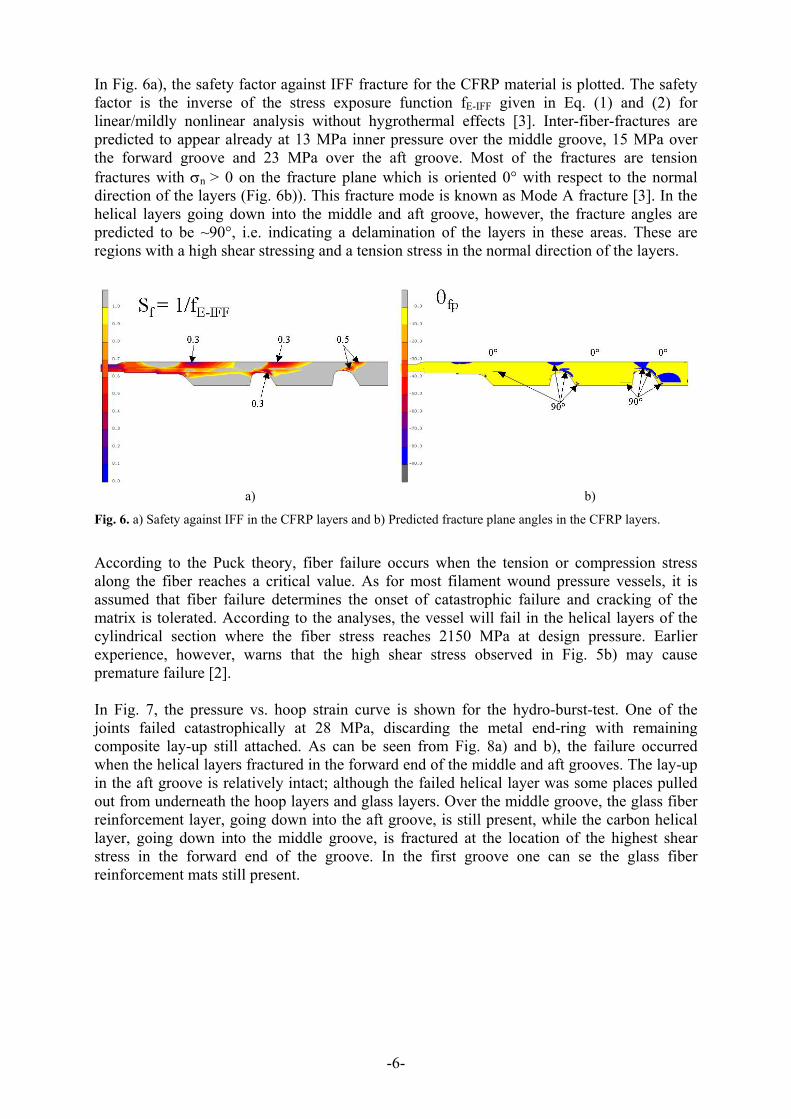
In Fig. 6a), the safety factor against IFF fracture for the CFRP material is plotted. The safety factor is the inverse of the stress exposure function fE-IFF given in Eq. (1) and (2) for linear/mildly nonlinear analysis without hygrothermal effects [3]. Inter-fiber-fractures are predicted to appear already at 13 MPa inner pressure over the middle groove, 15 MPa over the forward groove and 23 MPa over the aft groove. Most of the fractures are tension fractures with σn > 0 on the fracture plane which is oriented 0° with respect to the normal direction of the layers (Fig. 6b)). This fracture mode is known as Mode A fracture [3]. In the helical layers going down into the middle and aft groove, however, the fracture angles are predicted to be ~90°, i.e. indicating a delamination of the layers in these areas. These are regions with a high shear stressing and a tension stress in the normal direction of the layers.
a) b)
Fig. 6. a) Safety against IFF in the CFRP layers and b) Predicted fracture plane angles in the CFRP layers.
According to the Puck theory, fiber failure occurs when the tension or compression stress along the fiber reaches a critical value. As for most filament wound pressure vessels, it is assumed that fiber failure determines the onset of catastrophic failure and cracking of the matrix is tolerated. According to the analyses, the vessel will fail in the helical layers of the cylindrical section where the fiber stress reaches 2150 MPa at design pressure. Earlier experience, however, warns that the high shear stress observed in Fig. 5b) may cause premature failure [2]. In Fig. 7, the pressure vs. hoop strain curve is shown for the hydro-burst-test. One of the joints failed catastrophically at 28 MPa, discarding the metal end-ring with remaining composite lay-up still attached. As can be seen from Fig. 8a) and b), the failure occurred when the helical layers fractured in the forward end of the middle and aft grooves. The lay-up in the aft groove is relatively intact; although the failed helical layer was some places pulled out from underneath the hoop layers and glass layers. Over the middle groove, the glass fiber reinforcement layer, going down into the aft groove, is still present, while the carbon helical layer, going down into the middle groove, is fractured at the location of the highest shear stress in the forward end of the groove. In the first groove one can se the glass fiber reinforcement mats still present.
-6-

0
5
10
15
20
25
30
0 1000 2000 3000 4000 5000 6000 7000 8000 9000 10000Strain [µm/m]
Inne
r pre
ssur
e [M
Pa]
28 MPa
Fig. 7. Pressure vs. hoop strain in the cylindrical area of the tank.
Fig. 8. Failed end of the test vessel. The end-ring failed at 28 MPa due to fiber fracture into the groves
The joint that did not fail during testing was cut open and prepared for examination under the light-optical microscope (Fig. 9). Such an examination does not reveal the complete history of cracking of the specimen, only the state of the material after unloading can be observed. Cracks that are completely closed in the process of rapid unloading at the time of failure will be difficult to observe. Also, there are the processing faults and cracking due to cutting of the specimen to consider. In spite of these drawbacks, some striking agreements with the IFF prediction can be identified. One is the axial cracking of the hoop layers. Multiple cracks in the hoop layers with a 0° angle to the normal direction are observed, especially above the forward ends of the grooves as predicted. Another important prediction that is observed is the delamination of the helical layer down into the middle and aft grooves. It is clearly seen that the CFRP layers are split by a 90° angle fracture down into the grooves. In addition, the analyses predicted the observed cracking of the hoop layers down into the aft groove and the delamination in the helical layer above the forward groove. Of the predicted IFF failures that are not observed, are the 90° fractures in the hoop layers above the forward end of the grooves. Several production faults can be observed in Fig. 9. One is the porosity in the glass fiber reinforcements. Rather large voids are seen in nearly all glass reinforcements except for the first layers in the forward groove. Another is the delamination seen in the bottom of the middle and aft groove. Most likely, this is a result of poor compaction of the helical layer in the corner of the groove.
-7-

Fig. 9. Composite images of the joint that did not fail catastrophically. The picture on top were taken in a macroscope at ~3x magnification while the bottom micrographs were taken in a light optical microscope at 16x magnification.
Although the IFF cracking can be predicted quite accurately, the prediction of the final failure is not satisfying. If only tension and compression in the fiber direction are responsible for final fiber failure, the analyses predicts that fiber failure should have taken place in the cylindrical area at a much higher pressure. One IFF condition that has been known to cause fiber failure is the wedge type failure mechanism known as Mode C [3]. A compressive transverse stress combined with a shear loading have been found to produce fracture planes with angles 45-55° to the normal direction. This may cause stress concentrations on the surrounding layers and thereby a fiber fracture. The theoretical and experimental results in this case, however, show no sign of this failure mechanism. A major drawback of the present analyses is that no degradation or non-linear material behavior is taken into account. Consequently, a possible solution may be that inter fiber fracture leads to a stress redistribution and a tension stress concentration in the fiber direction that causes fiber failure down into the grooves. As shown in Fig. 5, the shear stress in the helical layer is very high down into the middle groove. Fig. 6 and Fig. 9 demonstrates, both theoretically and experimentally, that the helical layer will delaminate. This means that the load sharing between the +/-30° layers will be reduced locally, producing a stress concentration and ultimately a fiber failure. Effects of delamination are notoriously difficult to analyze using finite element methods, even when degradation of the material properties are included. For design purposes, it may therefore be necessary to take into account the effect of transverse stress on the fiber failure within the fiber failure criterion. A thorough study of the influence of transverse tension/compression stress on the fiber failure has revealed that fiber failure always occur at the same longitudinal stress independent of the applied transverse stress [14]. A similar study has to the authors knowledge not been carried out for the influence of shear stresses on the fiber failure. In the theoretical work by Hashin [12], however, the effect of shear stresses on the fiber failure were originally taken into consideration. This introduces a consistency with the idea that only the stresses acting in the plane of failure are responsible for failure. As most fiber failures are perpendicular to the fiber direction (Fig. 10), only the stresses acting in that plane need to be considered, i.e. σ11, τ12 and τ31. Hashin suggested an approximation for tension fiber fracture on the form
-8-

2||
231
212
2
||
11
⊥+−
++⎟
⎟⎠
⎞⎜⎜⎝
⎛=
fFFE RR
f ττσ for 011 >σ (4)
where is the tension fracture stress in the fiber direction and is the transverse shear
failure stress. Eq. (4) predicts fiber failure whenever f
+||R ⊥||fR
E-FF ≥1. In Hashins work [12], was taken as the matrix shear strength. However, because only fiber fracture is considered in Eq. (4), this value is expected to be higher than the one causing matrix failure. In Fig. 11, the fiber fracture stress exposure function is plotted. When this value is above 1, the material will experience a fiber fracture and the inverse value indicates the safety factor. A value of 110 was used for in order to obtain a predicted fiber failure down into the second groove at an inner pressure of ~29.5MPa, i.e. close to the experimental failure pressure of 28 MPa.
⊥||fR
⊥||fR
a) b) Fig. 10. SEM pictures of the fractured helical layer pulled out of the middle groove of the failed joint. a) Layers with +/- 30° orientation. b) Close up on fractured fibers showing a failure plane perpendicular to the fiber direction.
Fig. 11. The stress exposure function for fiber fracture given by Eq. (4). Key values are indicated for the helical layers.
-9-

5 CONCLUSION Puck’s failure theory provides accurate predictions for inter-fiber-fracture in fiber-reinforced composites. Its ability to predict both the failure level and the failure mode makes it a sound basis for further investigations into analyses of progressive failure. It was found, however, that severe shear stress concentrations have an influence on the fiber failure. By taking the shear stress into account, the present work shows that accurate prediction is possible for the final failure of the trap-lock joint. REFERENCES:
1. Tenden, S. and Fossumstuen, K, “IM Improvement of rocket motor by composite motor case”, AVT Fall 2002 Meetings on Advances in Rocket Performance Life and Disposal, Aalborg Denmark (2002)
2. Fjeldly, A. and Tenden, S., “Composite-to-metal joint development for filament wound rocket motor cases”, Proc. 14th SICOMP conference on Manufacturing and design of composites, Piteå Sweden (2003)
3. Puck, A. and Shurmann, H.,”Failure analysis of FRP laminates by means of physically based phenomenological models”, Compos. Sci Technol, 58, p.1045 (1998)
4. Puck, A. and Shurmann, H.,”Failure analysis of FRP laminates by means of physically based phenomenological models”, Compos. Sci Technol, 62, p.1633 (2002)
5. Puck, A., Kopp, J. and Knops, M., ”Guidelines for the determination of the parameters in Puck’s action plane strength criterion”, Compos. Sci Technol, 62, p. 371 (2002)
6. Carlsen, T. Ø., “Design of filament wound rocket motor cases”, Diploma thesis, Norwegian University of Science and Technology (2003)
7. Carlsen, T. Ø. and Fjeldly, T. A.,” Composite failure analysis using Puck’s failure criterion in MSC.Marc”, Proc. MSC Virtual Product development conference, Gothenburg (2003)
8. N.N., “MSC.Marc Volume A Theory and User Information v2003”, MSC.Software Corporation (2003)
9. Hinton, M. J., Kaddour, A. S. and Soden, P. D., “A comparison of the predictive capabilities of current failure theories for composite laminates, judged against experimental evidence”, Compos. Sci. Technol., 62, p 1725 (2002)
10. Soden, P. D., Kaddour, A. S. and Hinton M. J., “Recommendations for designers and researchers resulting from the world-wide failure exercise”, Compos Sci. Technol, 64, p. 589, (2004)
11. Hashin, Z. and Rotem, A., “A fatigue failure criterion for fiber-reinforced materials”, Journal of Composite materials, 7, p. 448 (1973)
12. Hashin, Z., “Failure criteria for unidirectional fiber composites”, J. Appl. Mech., 47, p. 329 (1980) 13. Kopp, J. and Michaeli, W., More Efficient Composite Component Design Using Action-Plane
Related IFF Strength Criteria, 43rd International SAMPE Symposium (1998) 14. Fischer, O. W., “Faserbruchgeschehen in kohlenstofffaserverstärken Kunststoffen”, Dr. Ing.
Dissertation, IKV, RWTH Aachen Germany (2003)
-10-


![Design of Optimum Filament Wound Pressure Vessel with ... · Paper: ASAT-16-082-ST Fukunaga et al. [3] presented two methods for determining the optimum shapes of filament-wound domes](https://img.pdfslide.net/doc/110x75/5b4614d07f8b9a114c8b5bf4/design-of-optimum-filament-wound-pressure-vessel-with-paper-asat-16-082-st.jpg)