Embed Size (px)
Citation preview
International Research Journal of Engineering and Technology (IRJET) e-ISSN: 2395 -0056
Volume: 03 Issue: 10 | Oct -2016 www.irjet.net p-ISSN: 2395-0072
© 2016, IRJET ISO 9001:2008 Certified Journal Page 762
FAILURE ANALYSIS OF YOKE JOINT ASSEMBLY
Mr. Anuj A. Muley1, Dr. M. J. Sheikh2, Dr. G. V. Thakre3
1 PG Scholar, Mechanical Engineering, Bapurao Deshmukh College of Engineering, Sevagram, Wardha , Maharashtra , India.
2 Professor, Mechanical Engineering, Bapurao Deshmukh College of Engineering, Sevagram, Wardha, Maharashtra, India.
3 Professor, Mechanical Engineering, Bapurao Deshmukh College of Engineering, Sevagram, Wardha, Maharashtra, India.
---------------------------------------------------------------------***--------------------------------------------------------------------- Abstract - A Yoke Joint is a positive, mechanical connection
between rotating shafts, which are usually not parallel but intersecting. The Yoke Joint consists of two forged steel yoke located close together and situated at right angle to each other. A spider hinges two yoke together. Since the arms of the spider are at right angles, the spider arm rocks backward and forward between extreme positions. It is widely used in vehicle drivelines and in some industrial applications. Yoke Joint is one of the important components of motion transmission system of vehicle. The Yoke Joint of ST-Bus Midi-712 model has been studied in this project. The design verification has been done using numerical relationship between various parameters. It is observed that the failure of Yoke Joint has been occurred due to induced stresses. The strength, deformation and other parameters of different materials namely SAE 1050 and SM45C has been compared. The CAD model of Yoke Joint has been prepared, using CREO PARAMETRIC-3.0. For Finite Element Analysis, this model is imported in ANSYS-14.0 (Workbench) where stress analysis has been carried out. The comparisons of SAE 1050 and SM45C material has been carried out based on various parameters. The enhancing results are obtained and design is found to be safe using SM45C material.
Key Words: Yoke Joint, Critical Stress, Numerical Methods, FEM.
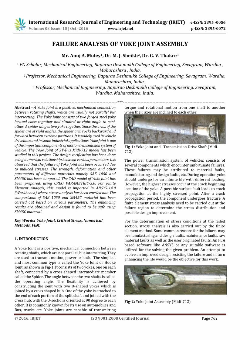
1. INTRODUCTION A Yoke Joint is a positive, mechanical connection between rotating shafts, which are not parallel, but intersecting. They are used to transmit motion, power or both. The simplest and most common type is called the Yoke Joint or Hooke Joint, as shown in Fig-1. It consists of two yokes, one on each shaft, connected by a cross-shaped intermediate member called the Spider. The angle between the two shafts is called the operating angle. The flexibility is achieved by constructing the joint with two U-shaped yokes which is joined by a cross shaped hub. One of the yoke is attached to the end of each portion of the split shaft and joined with the cross hub, with the U-sections oriented at 90 degree to each other. It is commonly known for its use on automobiles and Bus, trucks etc. Yoke joints are capable of transmitting
torque and rotational motion from one shaft to another when their axes are inclined to each other.
Fig-1: Yoke Joint and Transmission Drive Shaft (Midi-712)
The power transmission system of vehicles consists of several components which encounter unfortunate failures. These failures may be attributed to material faults, manufacturing and design faults, etc. During operation yoke should undergo for an infinite life with different loading. However, the highest stresses occur at the crack beginning location of the yoke. A possible surface fault leads to crack propagation at the highly stressed point. After a crack propagation period, the component undergoes fracture. A finite element stress analysis need to be carried out at the failure region to determine the stress distribution and possible design improvement.
For the determination of stress conditions at the failed section, stress analysis is also carried out by the finite element method. Some common reasons for the failures may be manufacturing and design faults, maintenance faults, raw material faults as well as the user originated faults. An FEA based software like ANSYS or any suitable software is utilized for the solving the given problem. An attempt to evolve an improved design resisting the failure and in turn enhancing the life would be the objective for this work.
Fig-2: Yoke Joint Assembly (Midi-712)
International Research Journal of Engineering and Technology (IRJET) e-ISSN: 2395 -0056
Volume: 03 Issue: 10 | Oct -2016 www.irjet.net p-ISSN: 2395-0072
© 2016, IRJET ISO 9001:2008 Certified Journal Page 763
1.2 DRIVE LINE ASSEMBLY:- The drive line assembly has several important functions. It must perform the following: Send turning power from the transmission to the rear
axle assembly. Flex and allow up-and-down movement of the rear axle
assembly. Provide a sliding action to adjust for changes in drive
line length. Provide a smooth power transfer. The assembly provides a path through which power is transmitted from the transmission to the drive axle assemblies or auxiliary equipment. Vehicles having a long wheelbase are equipped with a drive shaft that extends from the transmission or transfer case to a center support bearing and a drive shaft that extends from the center support bearing to the rear axle.
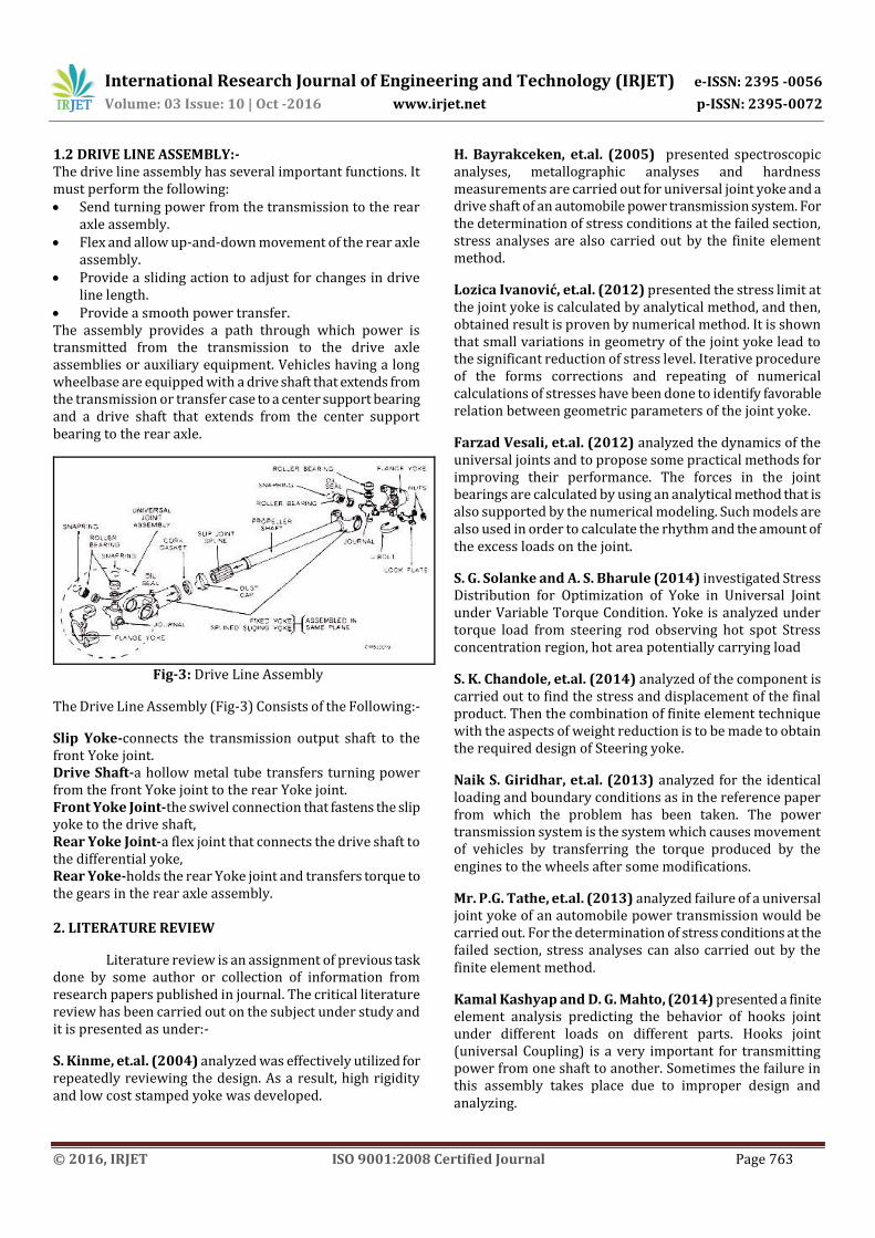
Fig-3: Drive Line Assembly
The Drive Line Assembly (Fig-3) Consists of the Following:-
Slip Yoke-connects the transmission output shaft to the front Yoke joint. Drive Shaft-a hollow metal tube transfers turning power from the front Yoke joint to the rear Yoke joint. Front Yoke Joint-the swivel connection that fastens the slip yoke to the drive shaft, Rear Yoke Joint-a flex joint that connects the drive shaft to the differential yoke, Rear Yoke-holds the rear Yoke joint and transfers torque to the gears in the rear axle assembly. 2. LITERATURE REVIEW
Literature review is an assignment of previous task done by some author or collection of information from research papers published in journal. The critical literature review has been carried out on the subject under study and it is presented as under:-
S. Kinme, et.al. (2004) analyzed was effectively utilized for repeatedly reviewing the design. As a result, high rigidity and low cost stamped yoke was developed.
H. Bayrakceken, et.al. (2005) presented spectroscopic analyses, metallographic analyses and hardness measurements are carried out for universal joint yoke and a drive shaft of an automobile power transmission system. For the determination of stress conditions at the failed section, stress analyses are also carried out by the finite element method.
Lozica Ivanović, et.al. (2012) presented the stress limit at the joint yoke is calculated by analytical method, and then, obtained result is proven by numerical method. It is shown that small variations in geometry of the joint yoke lead to the significant reduction of stress level. Iterative procedure of the forms corrections and repeating of numerical calculations of stresses have been done to identify favorable relation between geometric parameters of the joint yoke.
Farzad Vesali, et.al. (2012) analyzed the dynamics of the universal joints and to propose some practical methods for improving their performance. The forces in the joint bearings are calculated by using an analytical method that is also supported by the numerical modeling. Such models are also used in order to calculate the rhythm and the amount of the excess loads on the joint.
S. G. Solanke and A. S. Bharule (2014) investigated Stress Distribution for Optimization of Yoke in Universal Joint under Variable Torque Condition. Yoke is analyzed under torque load from steering rod observing hot spot Stress concentration region, hot area potentially carrying load
S. K. Chandole, et.al. (2014) analyzed of the component is carried out to find the stress and displacement of the final product. Then the combination of finite element technique with the aspects of weight reduction is to be made to obtain the required design of Steering yoke.
Naik S. Giridhar, et.al. (2013) analyzed for the identical loading and boundary conditions as in the reference paper from which the problem has been taken. The power transmission system is the system which causes movement of vehicles by transferring the torque produced by the engines to the wheels after some modifications.
Mr. P.G. Tathe, et.al. (2013) analyzed failure of a universal joint yoke of an automobile power transmission would be carried out. For the determination of stress conditions at the failed section, stress analyses can also carried out by the finite element method.
Kamal Kashyap and D. G. Mahto, (2014) presented a finite element analysis predicting the behavior of hooks joint under different loads on different parts. Hooks joint (universal Coupling) is a very important for transmitting power from one shaft to another. Sometimes the failure in this assembly takes place due to improper design and analyzing.
International Research Journal of Engineering and Technology (IRJET) e-ISSN: 2395 -0056
Volume: 03 Issue: 10 | Oct -2016 www.irjet.net p-ISSN: 2395-0072
© 2016, IRJET ISO 9001:2008 Certified Journal Page 764
Swapnil S. Kulkarni, et.al. (2014) presented failure analysis of a universal joint yoke is carried out by using Finite Element Methodology. The process of validation is sought through the physical Experimentation. The power transmission system of an automobile consist several components which sometimes encounter unfortunate failures.
Swati N. Date, et.al. (2014) analyzed of rigid flange coupling is carried out which is similar to the universal joint. In this Finite Element Method analysis of rigid flange coupling with the help of ANSYS Software for different torque and load condition and it verify by manual calculation.
Ritesh P. Neve (2015) analyzed is being performed on universal joint certain modifications are made in the existing geometry and analyses for the identical loading and boundary condition. Universal joint is a joint in a rigid rod that allows the rod to bend in any direction, and is commonly used in shafts that transmit rotary motion.
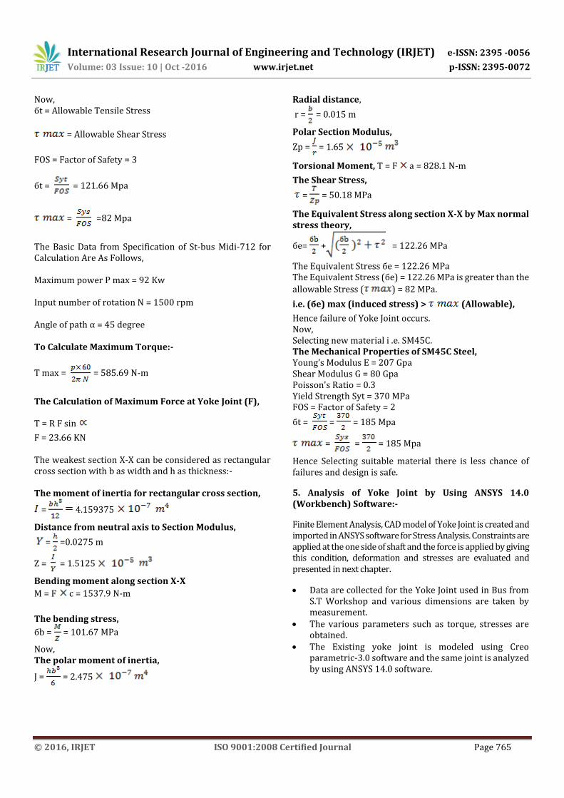
3. IDENTIFICATION OF PROBLEMS: By the discussion with the workers and executives of ST workshop, it is found that the yoke joint failure is a serious issue in ST Bus. It is found that the Yoke Joint fails mainly due to
I) Slip Yoke Fracture And
II) Flange Yoke Fracture
Hence it is decided to perform failure analysis to check the dimension of Yoke Joint with existing material in order to identify the other causes of failure.
It is planned to redesign the Yoke Joint if required. It is planned to check the strength of Yoke Joint by changing the material. It is decided to validate the design and analysis by CAD and FEM. 4. Failure of Yoke Joint Due To Bending and Shearing:-
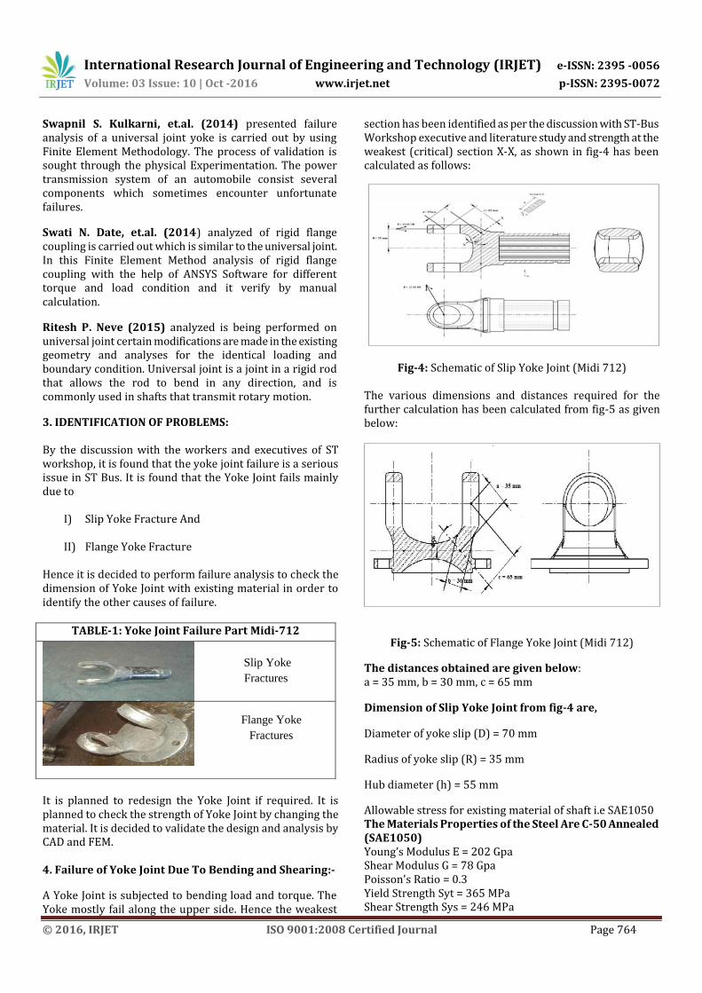
A Yoke Joint is subjected to bending load and torque. The Yoke mostly fail along the upper side. Hence the weakest
section has been identified as per the discussion with ST-Bus Workshop executive and literature study and strength at the weakest (critical) section X-X, as shown in fig-4 has been calculated as follows:
Fig-4: Schematic of Slip Yoke Joint (Midi 712)
The various dimensions and distances required for the further calculation has been calculated from fig-5 as given below:
Fig-5: Schematic of Flange Yoke Joint (Midi 712)
The distances obtained are given below: a = 35 mm, b = 30 mm, c = 65 mm
Dimension of Slip Yoke Joint from fig-4 are,
Diameter of yoke slip (D) = 70 mm
Radius of yoke slip (R) = 35 mm
Hub diameter (h) = 55 mm
Allowable stress for existing material of shaft i.e SAE1050 The Materials Properties of the Steel Are C-50 Annealed (SAE1050) Young’s Modulus E = 202 Gpa Shear Modulus G = 78 Gpa Poisson's Ratio = 0.3 Yield Strength Syt = 365 MPa Shear Strength Sys = 246 MPa
TABLE-1: Yoke Joint Failure Part Midi-712
Slip Yoke
Fractures
Flange Yoke
Fractures
International Research Journal of Engineering and Technology (IRJET) e-ISSN: 2395 -0056
Volume: 03 Issue: 10 | Oct -2016 www.irjet.net p-ISSN: 2395-0072
© 2016, IRJET ISO 9001:2008 Certified Journal Page 765
Now, бt = Allowable Tensile Stress
= Allowable Shear Stress
FOS = Factor of Safety = 3
бt = = 121.66 Mpa
= =82 Mpa
The Basic Data from Specification of St-bus Midi-712 for Calculation Are As Follows, Maximum power P max = 92 Kw Input number of rotation N = 1500 rpm Angle of path α = 45 degree To Calculate Maximum Torque:-
T max = = 585.69 N-m
The Calculation of Maximum Force at Yoke Joint (F),
T = R F sin
F = 23.66 KN The weakest section X-X can be considered as rectangular cross section with b as width and h as thickness:- The moment of inertia for rectangular cross section,
= 4.159375
Distance from neutral axis to Section Modulus,
= =0.0275 m
Z = = 1.5125
Bending moment along section X-X
M = F c = 1537.9 N-m
The bending stress,
бb = = 101.67 MPa
Now, The polar moment of inertia,
J = = 2.475
Radial distance,
r = = 0.015 m
Polar Section Modulus,
Zp = = 1.65
Torsional Moment, T = F a = 828.1 N-m
The Shear Stress,
= = 50.18 MPa
The Equivalent Stress along section X-X by Max normal stress theory,
бe= + = 122.26 MPa
The Equivalent Stress бe = 122.26 MPa The Equivalent Stress (бe) = 122.26 MPa is greater than the
allowable Stress ( ) = 82 MPa.
i.e. (бe) max (induced stress) > (Allowable),
Hence failure of Yoke Joint occurs. Now, Selecting new material i .e. SM45C. The Mechanical Properties of SM45C Steel, Young’s Modulus E = 207 Gpa Shear Modulus G = 80 Gpa Poisson's Ratio = 0.3 Yield Strength Syt = 370 MPa FOS = Factor of Safety = 2
бt = = = 185 Mpa
= = = 185 Mpa
Hence Selecting suitable material there is less chance of failures and design is safe.
5. Analysis of Yoke Joint by Using ANSYS 14.0 (Workbench) Software:-
Finite Element Analysis, CAD model of Yoke Joint is created and imported in ANSYS software for Stress Analysis. Constraints are applied at the one side of shaft and the force is applied by giving this condition, deformation and stresses are evaluated and presented in next chapter.
Data are collected for the Yoke Joint used in Bus from S.T Workshop and various dimensions are taken by measurement.
The various parameters such as torque, stresses are obtained.
The Existing yoke joint is modeled using Creo parametric-3.0 software and the same joint is analyzed by using ANSYS 14.0 software.
International Research Journal of Engineering and Technology (IRJET) e-ISSN: 2395 -0056
Volume: 03 Issue: 10 | Oct -2016 www.irjet.net p-ISSN: 2395-0072
© 2016, IRJET ISO 9001:2008 Certified Journal Page 766
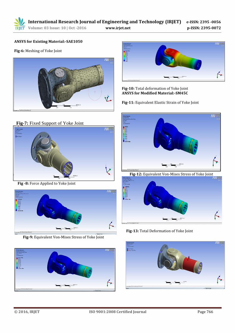
ANSYS for Existing Material:-SAE1050 Fig-6: Meshing of Yoke Joint
Fig -8: Force Applied to Yoke Joint
Fig-9: Equivalent Von-Mises Stress of Yoke Joint
Fig-10: Total deformation of Yoke Joint ANSYS for Modified Material:-SM45C Fig-11: Equivalent Elastic Strain of Yoke Joint
Fig-12: Equivalent Von-Mises Stress of Yoke Joint
Fig-13: Total Deformation of Yoke Joint
Fig-7: Fixed Support of Yoke Joint
International Research Journal of Engineering and Technology (IRJET) e-ISSN: 2395 -0056
Volume: 03 Issue: 10 | Oct -2016 www.irjet.net p-ISSN: 2395-0072
© 2016, IRJET ISO 9001:2008 Certified Journal Page 767
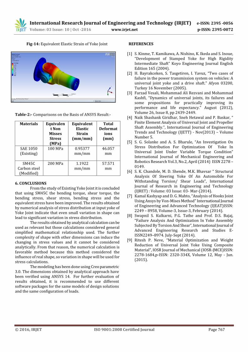
Fig-14: Equivalent Elastic Strain of Yoke Joint
Table-2:- Comparisons on the Basis of ANSYS Result:-
Materials Equivalent Non
Misses Stress (MPa)
Equivalent Elastic Strain
(mm/mm)
Total Deformat
ions (mm)
SAE 1050 (Existing)
100 MPa 0.95377 mm/mm
46.057 mm
SM45C Carbon steel (Modified)
200 MPa 1.1922 mm/mm
57.571 mm
6. CONCLUSIONS From the study of Existing Yoke Joint it is concluded that using SM45C the bending torque, shear torque, the bending stress, shear stress, bending stress and the equivalent stress have been improved. The results obtained by numerical analysis of stress distribution at input yoke of Yoke Joint indicate that even small variation in shape can lead to significant variation in stress distribution. The results obtained by analytical calculation can be used as relevant but those calculations considered general simplified mathematical relationship used. The further complexity of shape with other dimensions can induce the changing in stress values and it cannot be considered analytically. From that reason, the numerical calculation is favorable method because this method considered the influence of real shape, so variation in shape will be used for stress calculations.
The modeling has been done using Creo parametric 3.0. The dimensions obtained by analytical approach have been verified using ANSYS 14. For further evaluation of results obtained, it is recommended to use different software packages for the same models of design solutions and the same configuration of loads.
REFERENCES
[1] S. Kinme, T. Kamikawa, A. Nishino, K. Ikeda and S. Inoue, “Development of Stamped Yoke for High Rigidity Intermediate Shaft” Koyo Engineering Journal English Edition 165 (2004).
[2] H. Bayrakceken, S. Tasgetiren, I. Yavuz, “Two cases of failure in the power transmission system on vehicles: A universal joint yoke and a drive shaft.” Afyon 03200, Turkey 16 November (2005).
[3] Farzad Vesali, Mohammad Ali Rezvani and Mohammad Kashfi, “Dynamics of universal joints, its failures and some propositions for practically improving its performance and life expectancy.” August (2012), Volume 26, Issue 8, pp 2439-2449.
[4] Naik Shashank Giridhar, Sneh Hetawal and P. Baskar, “ Finite Element Analysis of Universal Joint and Propeller Shaft Assembly.”, International Journal of Engineering Trends and Technology (IJETT) - Nov(2013) – Volume Number 5.
[5] S. G. Solanke and A. S. Bharule, “An Investigation On Stress Distribution For Optimization Of Yoke In Universal Joint Under Variable Torque Condition” International Journal of Mechanical Engineering and Robotics Research Vol.3, No.2, April (2014) ISSN 2278 – 0149.
[6] S. K. Chandole, M. D. Shende, M.K. Bhavsar “ Structural Analysis Of Steering Yoke Of An Automobile For Withstanding Torsion/ Shear Loads”, International Journal of Research in Engineering and Technology (IJRET) : Volume: 03 Issue: 03- Mar-(2014).
[7] Kamal Kashyap and D. G. Mahto, “Analysis of Hooks Joint Using Ansys by Von-Mises Method” International Journal of Engineering and Advanced Technology (IJEAT)ISSN: 2249 – 8958, Volume-3, Issue-3, February (2014).
[8] Swapnil S. Kulkarni, P.G. Tathe and Prof. D.S. Bajaj, “Failure Analysis And Optimization In Yoke Assembly Subjected By Torsion And Shear”, International Journal of Advanced Engineering Research and Studies E-ISSN2249–8974. July-Sept (2014).
[9] Ritesh P. Neve, “Material Optimization and Weight Reduction of Universal Joint Yoke Using Composite Material”, IOSR Journal of Mechanical (IOSR-JMCE)ISSN: 2278-1684,p-ISSN: 2320-334X, Volume 12, May - Jun. (2015).