Embed Size (px)
Citation preview
FAILURE MECHANISM OF DEEP EXCAVATIONS IN SOFT CLAY: CASE STUDIES
Author: Tuan-Nghia Do
1
Introduction
Literature Review
Evaluation of Factors of Safety for Case Histories
Conclusions
Outlines
2
1
2
3
4
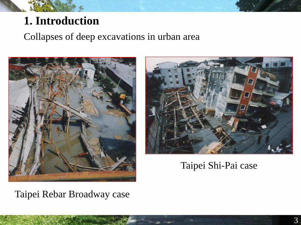
1. Introduction
Collapses of deep excavations in urban area
3
Taipei Shi-Pai case
Taipei Rebar Broadway case
4
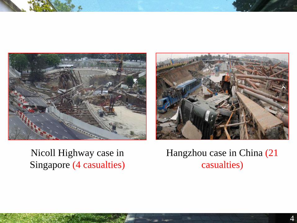
Nicoll Highway case in
Singapore (4 casualties)
Hangzhou case in China (21
casualties)
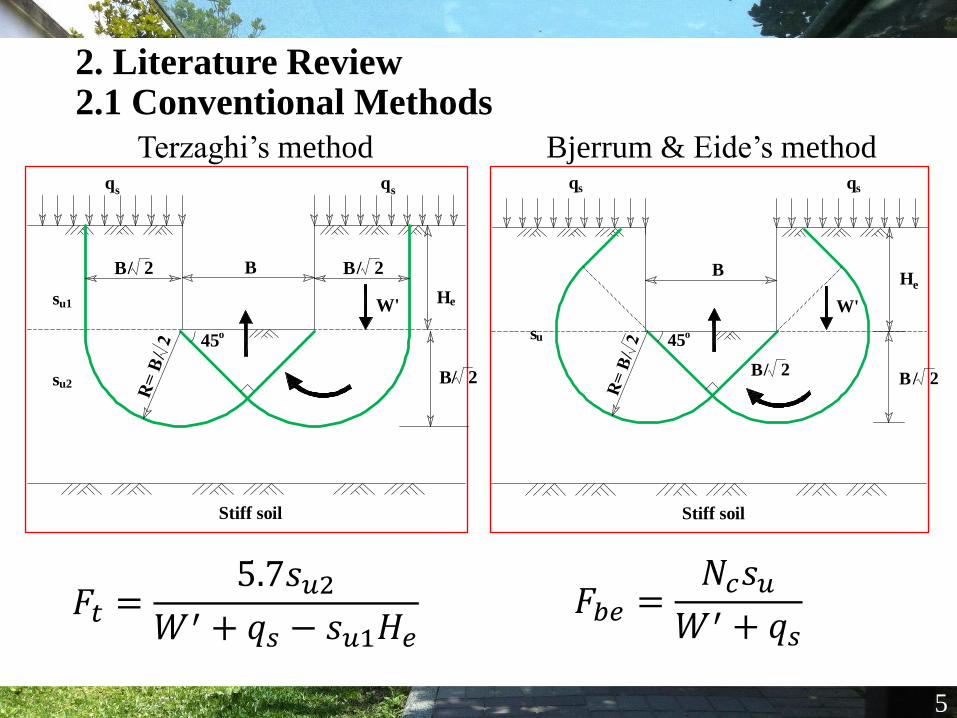
2. Literature Review2.1 Conventional Methods
Terzaghi’s method
5
Bjerrum & Eide’s method
𝐹𝑡 =5.7𝑠𝑢2
𝑊′ + 𝑞𝑠 − 𝑠𝑢1𝐻𝑒𝐹𝑏𝑒 =
𝑁𝑐𝑠𝑢𝑊′ + 𝑞𝑠
su2
su1 He
B
qsqs
Stiff soil
45o
2/B
2/B2/B
W'
B
Stiff soil
He
qs qs
su
2/B2/B
45o
W'
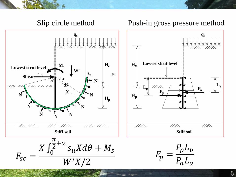
Slip circle method
6
Push-in gross pressure method
𝐹𝑠𝑐 =𝑋 0
𝜋2+𝛼
𝑠𝑢𝑋𝑑𝜃 +𝑀𝑠
𝑊′𝑋/2𝐹𝑝 =
𝑃𝑝𝐿𝑝
𝑃𝑎𝐿𝑎
X
qs
Lowest strut levelHe
Hp
Stiff soil
suW'
Shear
d
NN
N
N
N
N
N
N
Ms
su
su
su
su
susu
su
su
Lowest strut level
Stiff soil
PaPp
LaLp
He
Hp
qs
Nodal displacement
Str
ength
red
uct
ion
rati
o (
SR
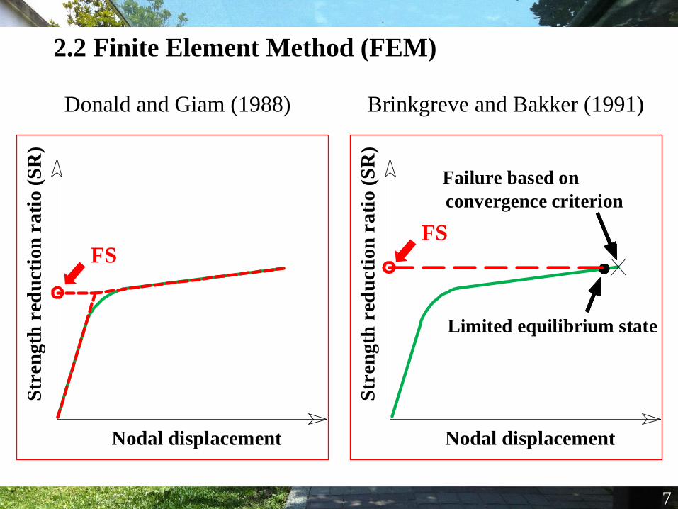
)2.2 Finite Element Method (FEM)
Brinkgreve and Bakker (1991)
7
Donald and Giam (1988)
Nodal displacement
Str
ength
red
uct
ion
rati
o (
SR
)
Failure based on
convergence criterion
Limited equilibrium state
FSFS
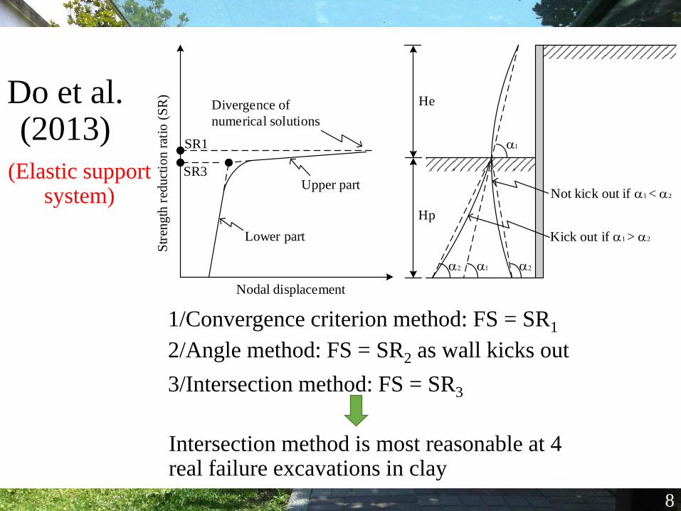
Do et al. (2013)
8
(Elastic support system)
1/Convergence criterion method: FS = SR1
2/Angle method: FS = SR2 as wall kicks out
3/Intersection method: FS = SR3
Intersection method is most reasonable at 4 real failure excavations in clay
Not kick out if 1 < 2
Kick out if 1 > 2
22
1
1
He
Hp
Lower part
Str
eng
th r
edu
ctio
n r
atio
(S
R)
Nodal displacement
Divergence of
numerical solutions
SR1
SR3Upper part
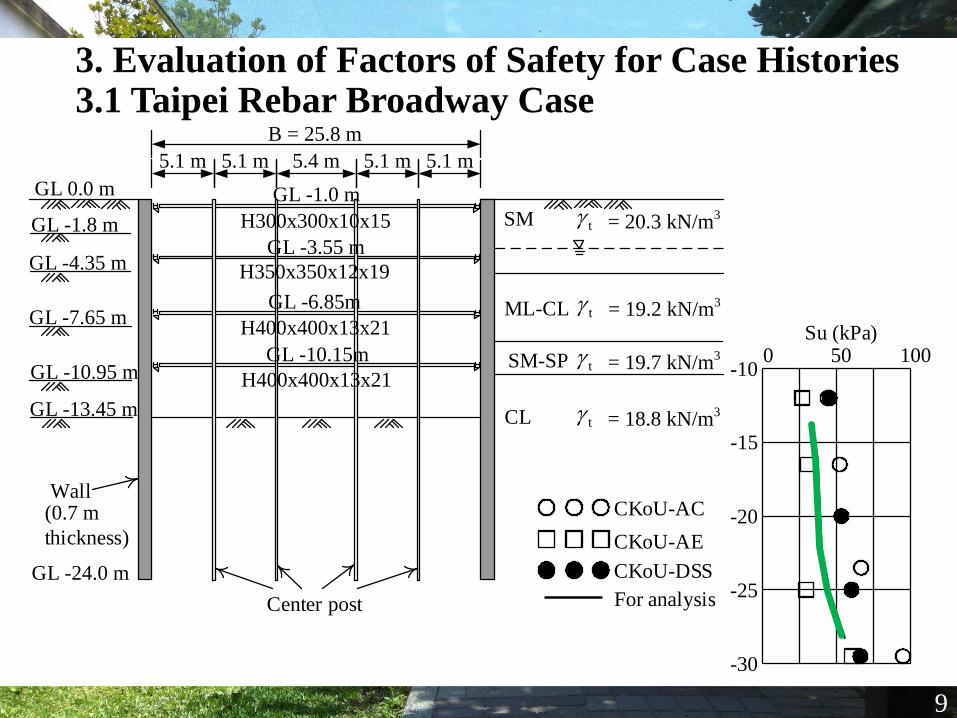
3. Evaluation of Factors of Safety for Case Histories3.1 Taipei Rebar Broadway Case
9
-10
-15
-20
-25
-30
0 50 100Su (kPa)
GL -1.8 m
GL -4.35 m
GL -7.65 m
GL -10.95 m
GL -13.45 m
SM
ML-CL
SM-SP t = 19.7 kN/m3
CL t = 18.8 kN/m3
GL -24.0 m
B = 25.8 m
t = 20.3 kN/m3
t = 19.2 kN/m3
(0.7 m
thickness)
5.1 m 5.1 m 5.1 m5.1 m5.4 m
Center post
GL -1.0 m
GL -3.55 m
GL -6.85m
GL -10.15m
H350x350x12x19
H400x400x13x21
H400x400x13x21
H300x300x10x15
GL 0.0 m
CKoU-AC
CKoU-AE
CKoU-DSS
For analysis
Wall
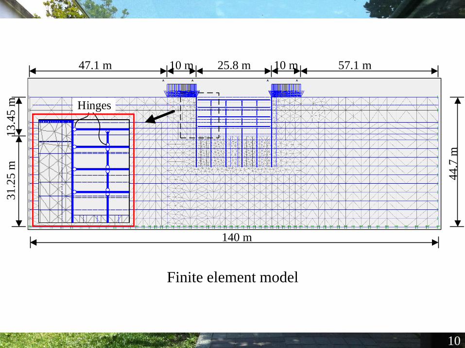
10
Finite element model
10 m
140 m
44
.7 m
13
.45
m3
1.2
5 m
25.8 m 57.1 m47.1 m 10 m
Hinges
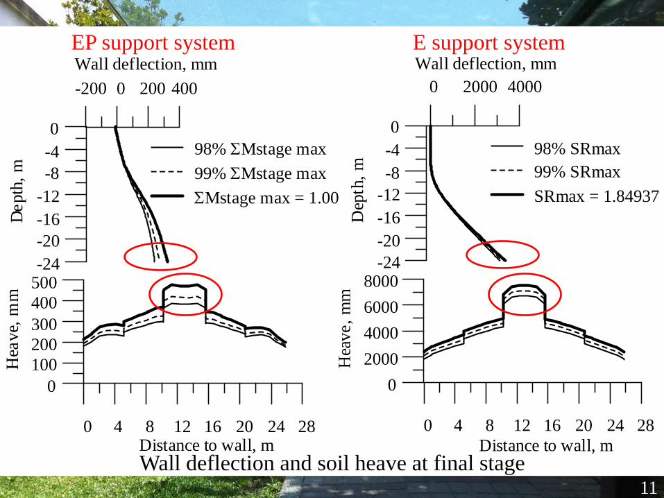
11
Wall deflection and soil heave at final stage
-200 0 200 400
Wall deflection, mm
-24
-20
-16
-12
-8
-4
0
De
pth
, m
0 4 8 12 16 20 24 28Distance to wall, m
0
100
200
300
400
500
Hea
ve,
mm
98% SMstage max
99% SMstage max
SMstage max = 1.00
0 2000 4000
Wall deflection, mm
-24
-20
-16
-12
-8
-4
0
Dep
th,
m
0 4 8 12 16 20 24 28
Distance to wall, m
0
2000
4000
6000
8000
Hea
ve,
mm
98% SRmax
99% SRmax
SRmax = 1.84937
EP support system E support system
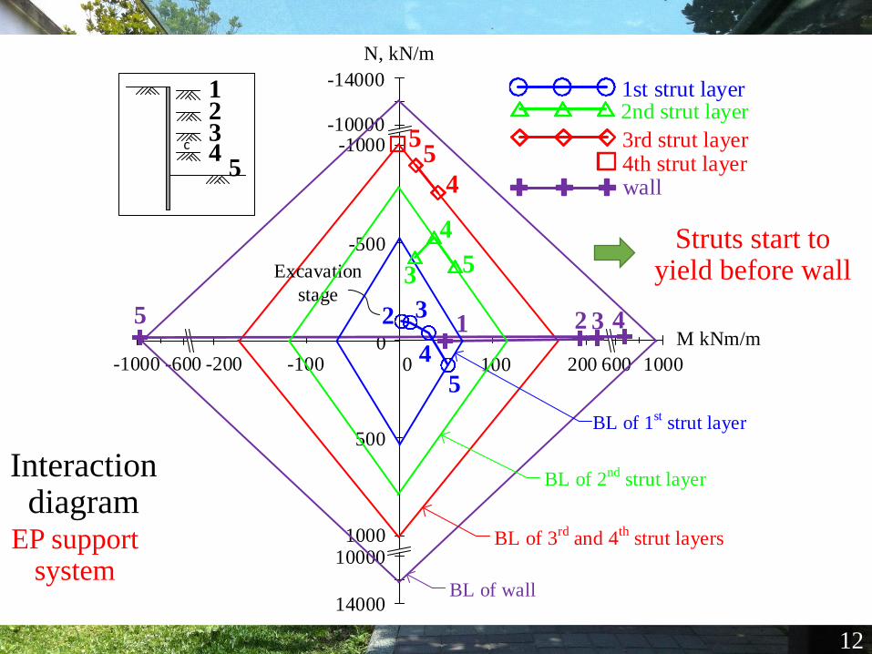
-1000 -600 -200 -100 0 200 600 1000
M kNm/m
-10000
-14000
0
-1000
N, kN/m
100
-500
500
100010000
14000
1234
5c
BL of 3rd
and 4th
strut layers
4
55
BL of wall
1 2 3 45
12
Interaction diagram
EP support system
BL of 1st strut layer
2 3
4
5
Excavation
stage
1st strut layer
BL of 2nd
strut layer
3
4
5
2nd strut layer
3rd strut layer4th strut layerwall
Struts start to yield before wall
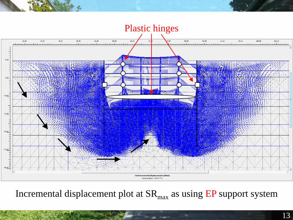
13
Incremental displacement plot at SRmax as using EP support system
Plastic hinges
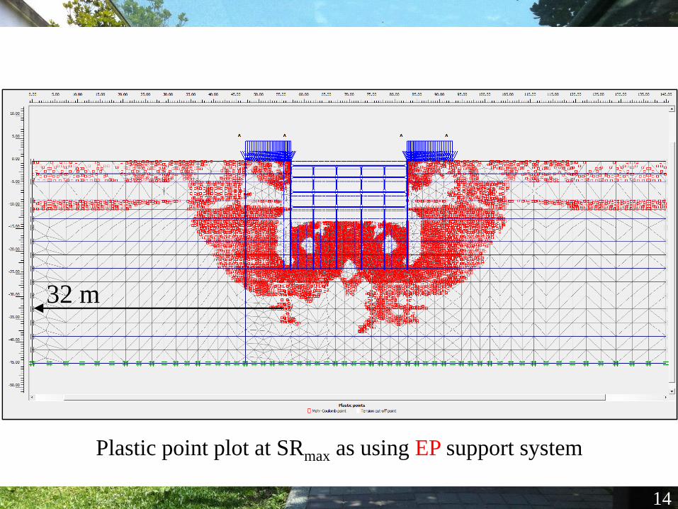
14
Plastic point plot at SRmax as using EP support system
32 m
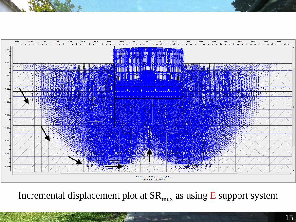
15
Incremental displacement plot at SRmax as using E support system
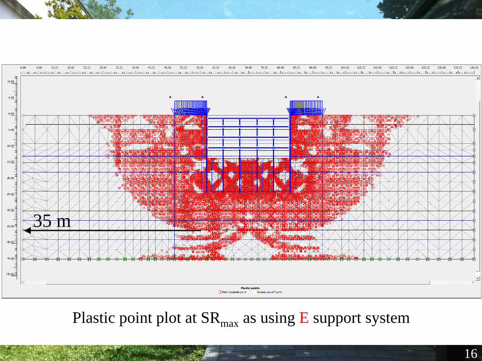
16
Plastic point plot at SRmax as using E support system
35 m
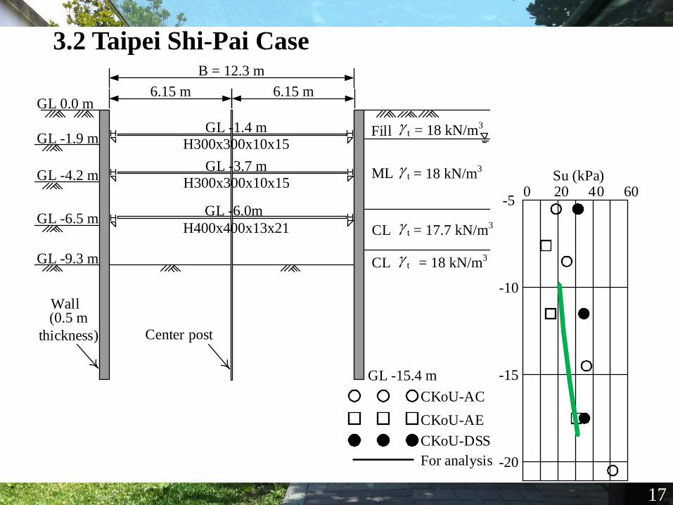
3.2 Taipei Shi-Pai Case
17
0 20 40 60Su (kPa)
-10
-15
-20
-5
Fill
ML
CL
CL
GL -15.4 m
t = 18 kN/m3
t = 18 kN/m3
t = 17.7 kN/m3
6.15 m
B = 12.3 m
6.15 m
Wall
Center post
GL -1.9 m
GL -4.2 m
GL -6.5 m
GL -9.3 m
GL 0.0 m
t = 18 kN/m3
GL -1.4 m
GL -3.7 m
GL -6.0m
H300x300x10x15
H300x300x10x15
H400x400x13x21
CKoU-AC
CKoU-AE
CKoU-DSS
For analysis
(0.5 m
thickness)
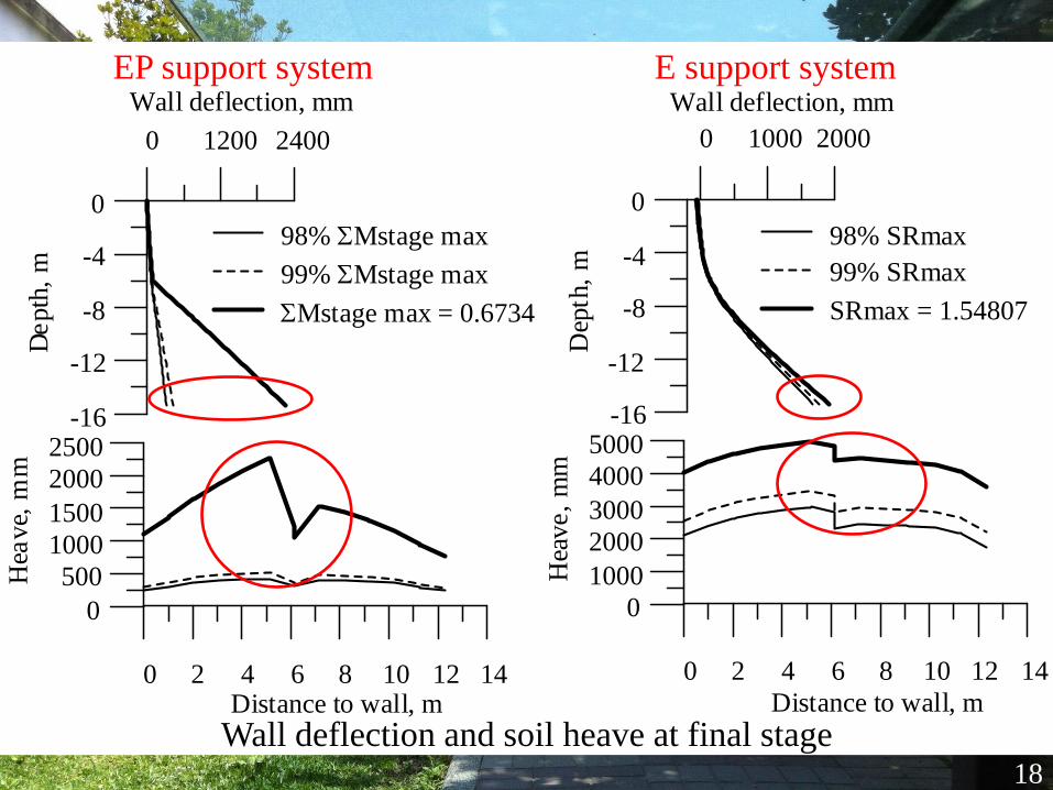
0 1000 2000
Wall deflection, mm
-16
-12
-8
-4
0
Dep
th,
m
0 2 4 6 8 10 12 14
Distance to wall, m
0
1000
2000
3000
4000
5000
Hea
ve,
mm
98% SRmax
99% SRmax
SRmax = 1.54807
0 1200 2400
Wall deflection, mm
-16
-12
-8
-4
0
De
pth
, m
0 2 4 6 8 10 12 14Distance to wall, m
0
500
1000
1500
2000
2500
Hea
ve,
mm
98% SMstage max
99% SMstage max
SMstage max = 0.6734
18
Wall deflection and soil heave at final stage
EP support system E support system
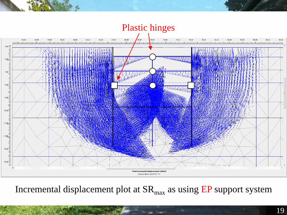
19
Incremental displacement plot at SRmax as using EP support system
Plastic hinges
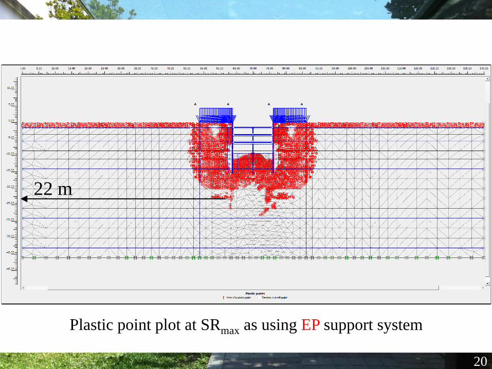
20
Plastic point plot at SRmax as using EP support system
22 m
21
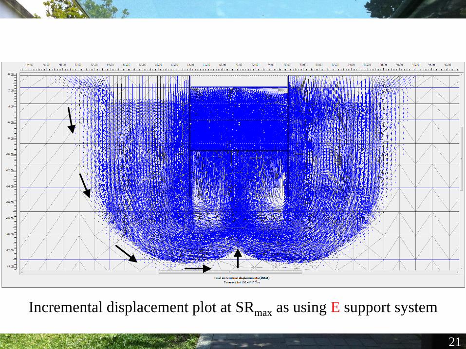
Incremental displacement plot at SRmax as using E support system
22
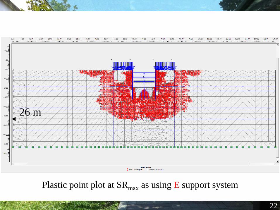
Plastic point plot at SRmax as using E support system
26 m
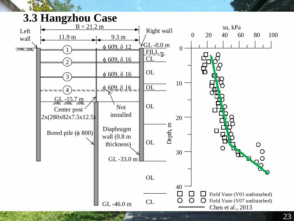
3.3 Hangzhou Case
23
0 20 40 60 80 100
su, kPa
40
30
20
10
0
Dept
h, m
Field Vane (V01 undisturbed)
Field Vane (V07 undisturbed)
Chen et al., 2013
FILLCL
OL
OL
OL
OL
OL
CL
GL -15.7 m
GL -0.0 mf 609, d 12
f 609, d 16
f 609, d 16
11.9 m
Diaphragm
wall (0.8 m
thickness)
B = 21.2 m
9.3 m
Bored pile (f 800)
GL -46.0 m
Center post
2x(280x82x7.5x12.5)
GL -33.0 m
1
2
3
f 609, d 164
Not
installed
Left
wall
Right wall
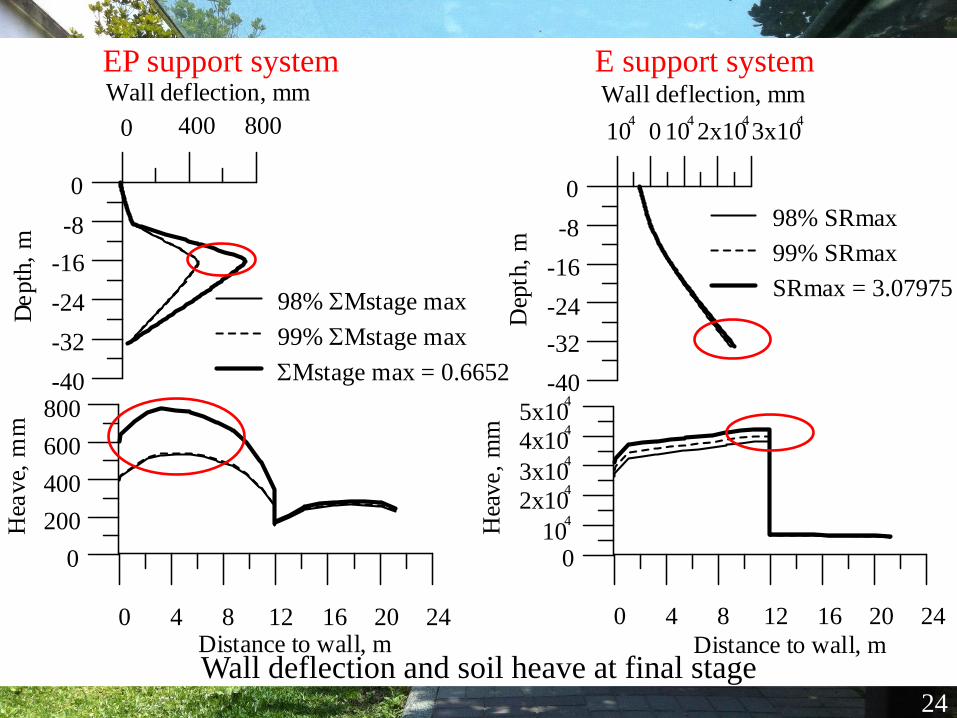
0 400 800
Wall deflection, mm
-40
-32
-24
-16
-8
0
De
pth
, m
0 4 8 12 16 20 24Distance to wall, m
0
200
400
600
800
Hea
ve,
mm
98% SMstage max
99% SMstage max
SMstage max = 0.6652
104
0 1042x10
43x10
4
Wall deflection, mm
-40
-32
-24
-16
-8
0
Dep
th,
m
0 4 8 12 16 20 24
Distance to wall, m
010
4
2x10⁴
3x10⁴
4x10⁴
5x10⁴
Hea
ve,
mm
98% SRmax
99% SRmax
SRmax = 3.07975
24
Wall deflection and soil heave at final stage
EP support system E support system
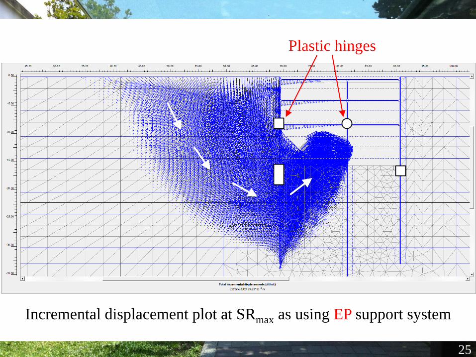
25
Incremental displacement plot at SRmax as using EP support system
Plastic hinges
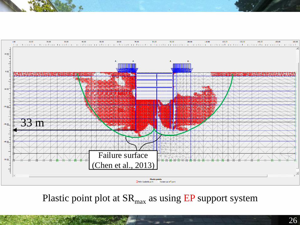
26
Plastic point plot at SRmax as using EP support system
33 m
Failure surface
(Chen et al., 2013)
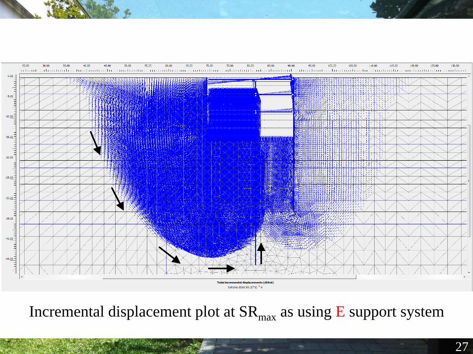
27
Incremental displacement plot at SRmax as using E support system
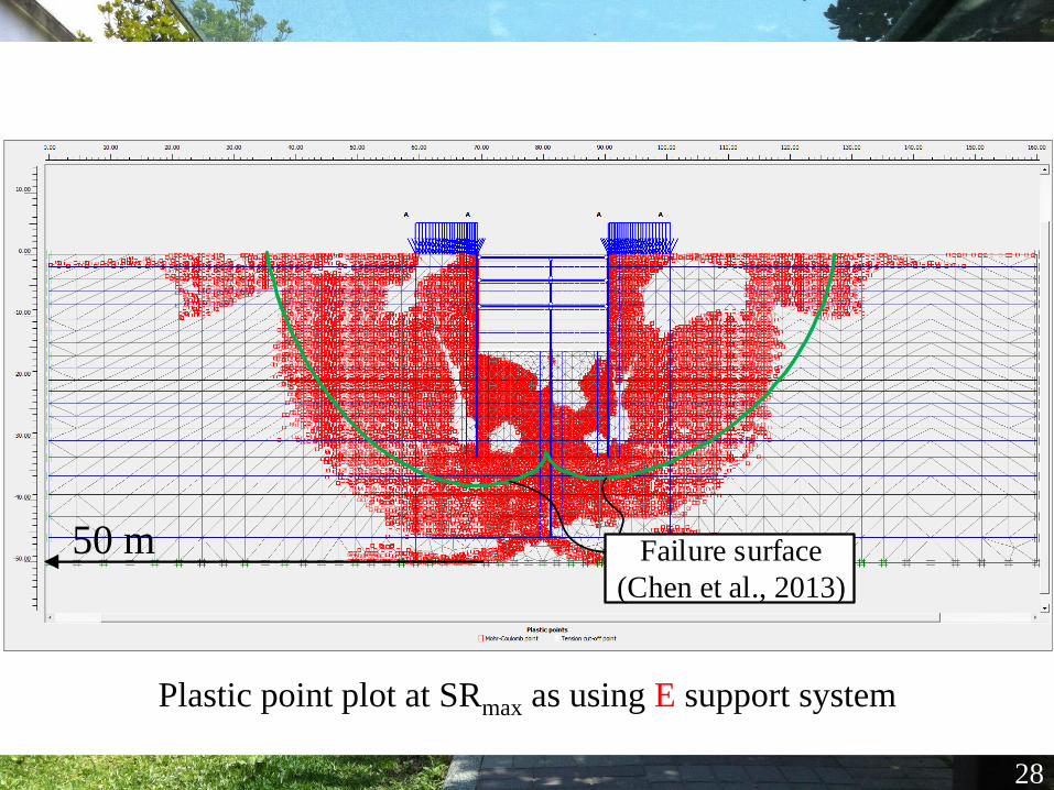
28
Plastic point plot at SRmax as using E support system
50 m Failure surface
(Chen et al., 2013)
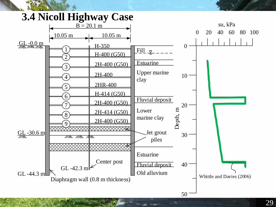
3.4 Nicoll Highway Case
29
0 20 40 60 80 100
su, kPa
50
40
30
20
10
0
De
pth
, m
Whittle and Davies (2006)
Fluvial deposit
Fluvial deposit
GL -0.0 m
GL -44.3 m
Fill
Estuarine
Upper marine
clay
Lower
marine clay
Estuarine
Old alluvium
10.05 m
Diaphragm wall (0.8 m thickness)
B = 20.1 m
10.05 m
GL -42.3 m
H-350
H-400 (G50)
2H-400 (G50)
2H-400
2HR-400
H-414 (G50)
2H-400 (G50)
2H-414 (G50)
2H-400 (G50)
GL -30.6 m
Center post
1
2
3
4
5
6
7
8
9
Jet grout
piles
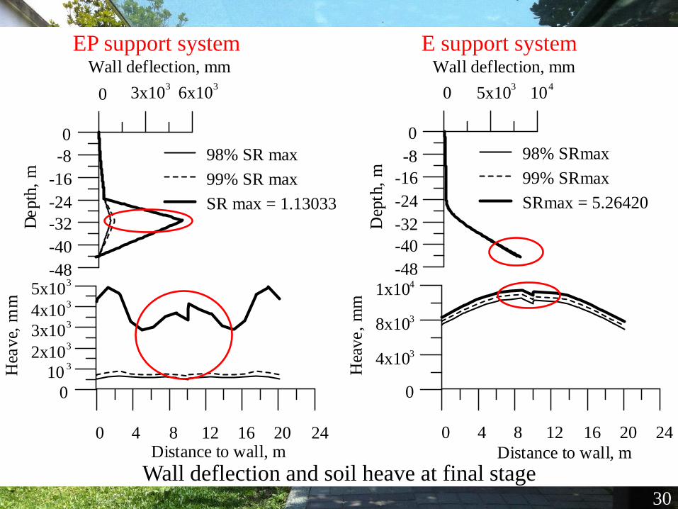
0 3x10³
6x10³
Wall deflection, mm
-48
-40
-32
-24
-16
-8
0
De
pth
, m
0 4 8 12 16 20 24Distance to wall, m
0
103
2x10³
3x10³
4x10³
5x10³
Hea
ve,
mm
98% SR max
99% SR max
SR max = 1.13033
0 5x10³
104
Wall deflection, mm
-48
-40
-32
-24
-16
-8
0
Dep
th,
m
0 4 8 12 16 20 24
Distance to wall, m
0
4x10³
8x10³
1x10⁴
Hea
ve,
mm
98% SRmax
99% SRmax
SRmax = 5.26420
30
Wall deflection and soil heave at final stage
EP support system E support system
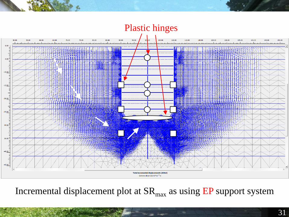
31
Incremental displacement plot at SRmax as using EP support system
Plastic hinges
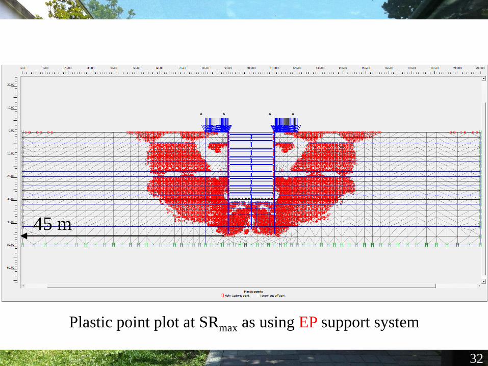
32
Plastic point plot at SRmax as using EP support system
45 m
33
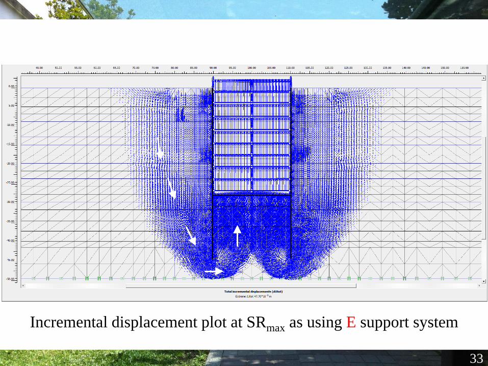
Incremental displacement plot at SRmax as using E support system
34
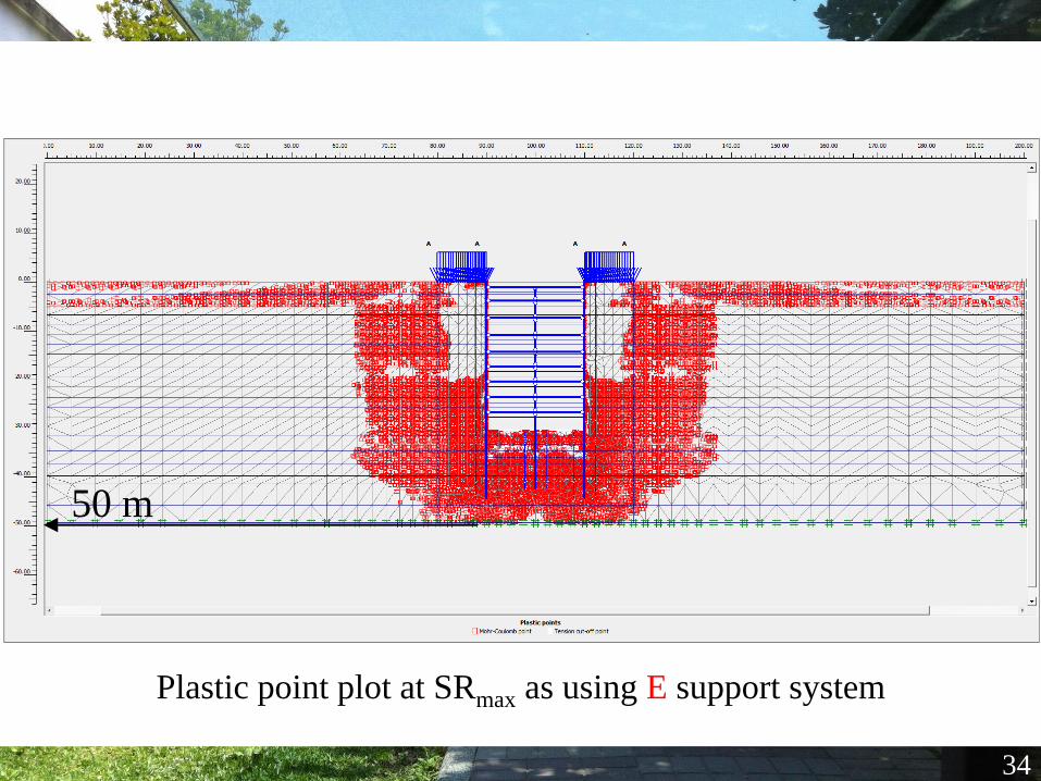
Plastic point plot at SRmax as using E support system
50 m
35
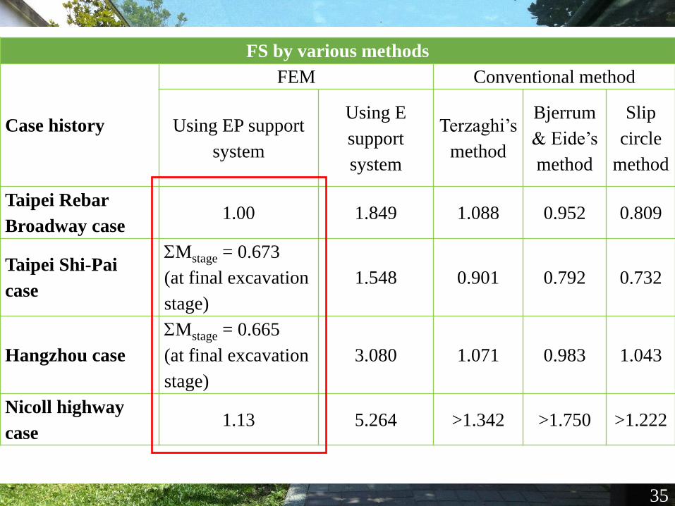
FS by various methods
Case history
FEM Conventional method
Using EP support
system
Using E
support
system
Terzaghi’s
method
Bjerrum
& Eide’s
method
Slip
circle
method
Taipei Rebar
Broadway case1.00 1.849 1.088 0.952 0.809
Taipei Shi-Pai
case
SMstage = 0.673
(at final excavation
stage)
1.548 0.901 0.792 0.732
Hangzhou case
SMstage = 0.665
(at final excavation
stage)
3.080 1.071 0.983 1.043
Nicoll highway
case1.13 5.264 >1.342 >1.750 >1.222
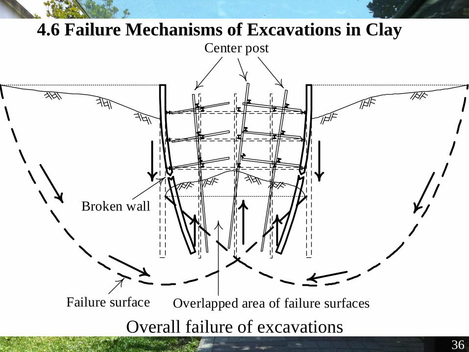
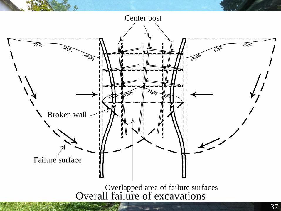
4.6 Failure Mechanisms of Excavations in Clay
36
Overall failure of excavations
Failure surface
Center post
Overlapped area of failure surfaces
Broken wall
Center post
Failure surface
Overlapped area of failure surfaces
Broken wall
37
Overall failure of excavations
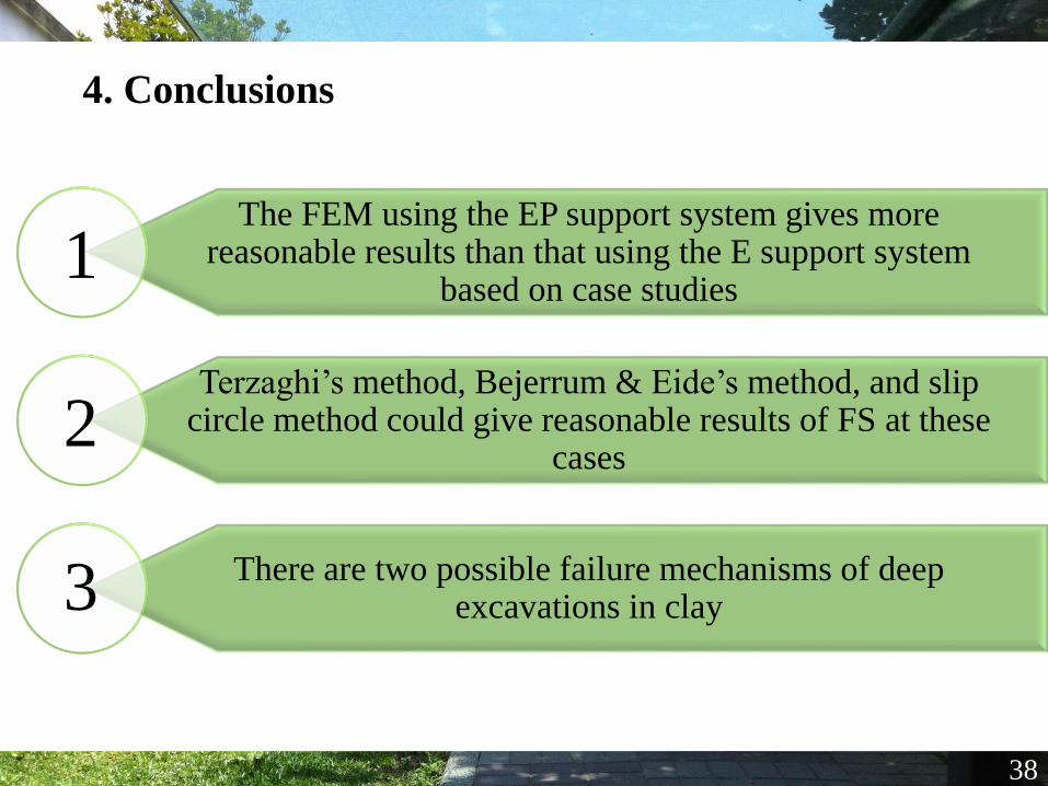
4. Conclusions
38
The FEM using the EP support system gives more reasonable results than that using the E support system
based on case studies
Terzaghi’s method, Bejerrum & Eide’s method, and slip circle method could give reasonable results of FS at these
cases
There are two possible failure mechanisms of deep excavations in clay
1
2
3

39
THANK YOU