Embed Size (px)
Citation preview
The document was prepared using best effort. The authors make no warranty of any kind and shall not be liable in any event for incidental or consequential damages in connection with the application of the document.
© All rights reserved.
Failure Modes, Effects and Diagnostic Analysis
Project:
CB/CBA/CBB/CBA300 Series Scotch Yoke Actuators
Company:
Valve Automation
Emerson Automation Solutions
Houston, Texas
USA
Contract Number: Q16/06-010
Report No.: EAS 16/06-010 R002
Version V1, Revision R1, December 7, 2016
Steven Close
© exida EAS 16-06-010 R002 V1R1 FMEDA CB Series Actuator.docx
T-126 V1,R1 exida 80 N. Main St, Sellersville, PA 18960 Page 2 of 28
Management Summary
This report summarizes the results of the hardware assessment in the form of a Failure Modes, Effects, and Diagnostic Analysis (FMEDA) of the CB/CBA/CBB/CBA300 Series Scotch Yoke Actuators. A Failure Modes, Effects, and Diagnostic Analysis is one of the steps to be taken to achieve functional safety certification per IEC 61508 of a device. From the FMEDA, failure rates are determined. The FMEDA that is described in this report concerns only the hardware of the CB/CBA/CBB/CBA300 Series Scotch Yoke Actuators. For full functional safety certification purposes all requirements of IEC 61508 must be considered.
The CB/CBA/CBB/CBA300 Series Scotch Yoke Actuators are mechanical devices that convert pneumatic input into rotary mechanical motion, i.e. quarter-turn actuators. The safety function of the CB/CBA/CBB/CBA300 Series Scotch Yoke Actuators is to move a 1/4 turn device to the safe position in the time specified. Table 1 gives an overview of the different versions that were considered in the FMEDA of the CB/CBA/CBB/CBA300 Series Scotch Yoke Actuators.
Note: the SIF designer is responsible for determining if the Latching and/or Override functions are suitable for the application. The end user qualified personnel are responsible for determining if it is safe to manually Latch/Unlatch or Override the Valves position.
Table 1 gives an overview of the different versions that were considered in this FMEDA of the CB/CBA/CBB/CBA300 Series Scotch Yoke Actuators.
Table 1 Version Overview
CB Series, Pneumatic, SR Pneumatic CB/CBA/CBB/CBA300 Series Scotch Yoke Actuators, Spring-Return
CB Series, Pneumatic, DA Pneumatic CB/CBA/CBB/CBA300 Series Scotch Yoke Actuators, Double Acting
The CB/CBA/CBB/CBA300 Series Scotch Yoke Actuators is classified as a device that is part of a Type A1 element according to IEC 61508, having a hardware fault tolerance of 0.
The failure rate data used for this analysis meets the exida criteria for Route 2H. See Section 5.2.
Therefore, the CB/CBA/CBB/CBA300 Series Scotch Yoke Actuators can be classified as a 2H
device when the listed failure rates are used. When 2H data is used for all of the devices in an element, then the element meets the hardware architectural constraints up to SIL 2 at HFT=0 (or SIL 3 @ HFT=1) per Route 2H. If Route 2H is not applicable for the entire final element, the architectural constraints will need to be evaluated per Route 1H.
The failure rates for the CB/CBA/CBB/CBA300 Series Scotch Yoke Actuators are listed in section 4.4.
These failure rates are valid for the useful lifetime of the product, see Appendix A.
The failure rates listed in this report do not include failures due to wear-out of any components. They reflect random failures and include failures due to external events, such as unexpected use, see section 4.2.2.
1 Type A element: “Non-Complex” element (using discrete components); for details see 7.4.4.1.2 of IEC 61508-2, ed2, 2010.
© exida EAS 16-06-010 R002 V1R1 FMEDA CB Series Actuator.docx
T-126 V1,R1 exida 80 N. Main St, Sellersville, PA 18960 Page 3 of 28
A user of the CB/CBA/CBB/CBA300 Series Scotch Yoke Actuators can utilize these failure rates in a probabilistic model of a safety instrumented function (SIF) to determine suitability in part for safety instrumented system (SIS) usage in a particular safety integrity level (SIL). A full table of failure rates is presented in section 4.4 along with all assumptions.
© exida EAS 16-06-010 R002 V1R1 FMEDA CB Series Actuator.docx
T-126 V1,R1 exida 80 N. Main St, Sellersville, PA 18960 Page 4 of 28
Table of Contents
1 Purpose and Scope ........................................................................................................ 5
2 Project Management ...................................................................................................... 6
2.1 exida ................................................................................................................................. 6
2.2 Roles of the parties involved .............................................................................................. 6
2.3 Standards and literature used ............................................................................................ 6
2.4 Reference documents ....................................................................................................... 7
2.4.1 Documentation provided by Valve Automation Emerson Automation Solutions ......... 7
2.4.2 Documentation generated by exida .......................................................................... 7
3 Product Description ........................................................................................................ 8
4 Failure Modes, Effects, and Diagnostic Analysis .......................................................... 10
4.1 Failure categories description .......................................................................................... 10
4.2 Methodology – FMEDA, failure rates ............................................................................... 10
4.2.1 FMEDA ................................................................................................................... 10
4.2.2 Failure rates ............................................................................................................ 11
4.3 Assumptions .................................................................................................................... 11
4.4 Results ............................................................................................................................ 12
5 Using the FMEDA Results ............................................................................................ 14
5.1 PFDavg calculation CB/CBA/CBB/CBA300 Series Scotch Yoke Actuators........................ 14
5.2 exida Route 2H Criteria.................................................................................................... 14
6 Terms and Definitions ................................................................................................... 16
7 Status of the Document ................................................................................................ 18
7.1 Liability ............................................................................................................................ 18
7.2 Version History ................................................................................................................ 18
7.3 Future enhancements ...................................................................................................... 18
7.4 Release signatures .......................................................................................................... 18
Appendix A Lifetime of Critical Components ................................................................ 19
Appendix B Proof Tests to Reveal Dangerous Undetected Faults .............................. 20
B.1 Suggested Proof Test ...................................................................................................... 20
B.2 Proof Test Coverage ....................................................................................................... 20
Appendix C exida Environmental Profiles ................................................................... 22
Appendix D Determining Safety Integrity Level ............................................................ 23
Appendix E Site Safety Index ...................................................................................... 27
E.1 Site Safety Index Profiles................................................................................................. 27
E.2 Site Safety Index Failure Rates – CB/CBA/CBB/CBA300 Series Scotch Yoke Actuators 28
© exida EAS 16-06-010 R002 V1R1 FMEDA CB Series Actuator.docx
T-126 V1,R1 exida 80 N. Main St, Sellersville, PA 18960 Page 5 of 28
1 Purpose and Scope
This document shall describe the results of the hardware assessment in the form of the Failure Modes, Effects and Diagnostic Analysis carried out on the CB/CBA/CBB/CBA300 Series Scotch Yoke Actuators. From this, failure rates and example PFDavg values may be calculated.
The information in this report can be used to evaluate whether an element meets the average Probability of Failure on Demand (PFDavg) requirements and if applicable, the architectural constraints / minimum hardware fault tolerance requirements per IEC 61508 / IEC 61511.
A FMEDA is part of the effort needed to achieve full certification per IEC 61508 or other relevant functional safety standard.
© exida EAS 16-06-010 R002 V1R1 FMEDA CB Series Actuator.docx
T-126 V1,R1 exida 80 N. Main St, Sellersville, PA 18960 Page 6 of 28
2 Project Management
2.1 exida
exida is one of the world’s leading accredited Certification Bodies and knowledge companies specializing in automation system safety and availability with over 400 person years of cumulative experience in functional safety. Founded by several of the world’s top reliability and safety experts
from assessment organizations and manufacturers, exida is a global company with offices around
the world. exida offers training, coaching, project oriented system consulting services, safety lifecycle engineering tools, detailed product assurance, cyber-security and functional safety
certification, and a collection of on-line safety and reliability resources. exida maintains the largest process equipment database of failure rates and failure modes with over 200 billion unit operating hours.
2.2 Roles of the parties involved
Valve Automation Emerson Automation Solutions Manufacturer of the CB/CBA/CBB/CBA300 Series Scotch Yoke Actuators
exida Performed the hardware assessment
Valve Automation Emerson Automation Solutions contracted exida in June 2016 with the hardware assessment of the above-mentioned device.
2.3 Standards and literature used
The services delivered by exida were performed based on the following standards / literature.
[N1] IEC 61508-2: ed2, 2010 Functional Safety of Electrical/Electronic/Programmable Electronic Safety-Related Systems
[N2] Mechanical Component Reliability Handbook, 4th Edition, 2016
exida LLC, Electrical & Mechanical Component Reliability Handbook, Fourth Edition, 2016 (pending publication, not publically available at the time of this report)
[N3] Safety Equipment Reliability Handbook, 3rd Edition, 2007
exida LLC, Safety Equipment Reliability Handbook, Third Edition, 2007, ISBN 978-0-9727234-9-7
[N4] Goble, W.M. 2010 Control Systems Safety Evaluation and Reliability, 3rd edition, ISA, ISBN 97B-1-934394-80-9. Reference on FMEDA methods
[N5] IEC 60654-1:1993-02, second edition
Industrial-process measurement and control equipment – Operating conditions – Part 1: Climatic condition
[N6] O’Brien, C. & Bredemeyer, L., 2009
exida LLC., Final Elements & the IEC 61508 and IEC Functional Safety Standards, 2009, ISBN 978-1-9934977-01-9
[N7] Scaling the Three Barriers, Recorded Web Seminar, June 2013,
http://www.exida.com/Webinars/Recordings/SIF-Verification-Scaling-the-Three-Barriers
© exida EAS 16-06-010 R002 V1R1 FMEDA CB Series Actuator.docx
T-126 V1,R1 exida 80 N. Main St, Sellersville, PA 18960 Page 7 of 28
[N8] Meeting Architecture Constraints in SIF Design, Recorded Web Seminar, March 2013
http://www.exida.com/Webinars/Recordings/Meeting-Architecture-Constraints-in-SIF-Design
[N9] White Paper
November 1999
“Using a Failure Modes, Effects and Diagnostic Analysis (FMEDA) to Measure Diagnostic Coverage in Programmable Electronic Systems”, W. M. Goble and A. C. Brombacher, Reliability Engineering and System Safety, Vol. 66, No. 2, November 1999
[N10] White Paper
July 2015
www.exida.com
“The Key Variables Needed for PFDavg Calculation,” White Paper, Iwan van Beurden, William Goble, Version 1.1, July 2015
http://www.exida.com/Resources/Whitepapers/the-key-variables-needed-for-pfdavg-calculation
2.4 Reference documents
2.4.1 Documentation provided by Valve Automation Emerson Automation Solutions
[D1] VA129743, Rev N, 11/05/2007
CBA300-SRX Assembly Drawing
[D2] 062910, Rev F, 4/02 Exploded Detail CB415-SR, CB520-SR, CB725-SR Actuators
[D3] 129742, Rev F, 4/21/2007 CBA 300 Assembly Drawing
2.4.2 Documentation generated by exida
[R1] EAS 16-06-010 FMEDA CB Series Actuator.xls, 6/1/2016
Failure Modes, Effects, and Diagnostic Analysis – CB/CBA/CBB/CBA300 Series Scotch Yoke Actuators, Pneumatic (internal document)
[R2] EAS 16-06-010 R002 V1R1 FMEDA CB Series Actuator.docx, 7-Dec-16
FMEDA report, CB/CBA/CBB/CBA300 Series Scotch Yoke Actuators (this report)
© exida EAS 16-06-010 R002 V1R1 FMEDA CB Series Actuator.docx
T-126 V1,R1 exida 80 N. Main St, Sellersville, PA 18960 Page 8 of 28
3 Product Description
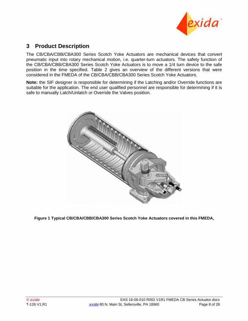
The CB/CBA/CBB/CBA300 Series Scotch Yoke Actuators are mechanical devices that convert pneumatic input into rotary mechanical motion, i.e. quarter-turn actuators. The safety function of the CB/CBA/CBB/CBA300 Series Scotch Yoke Actuators is to move a 1/4 turn device to the safe position in the time specified. Table 2 gives an overview of the different versions that were considered in the FMEDA of the CB/CBA/CBB/CBA300 Series Scotch Yoke Actuators.
Note: the SIF designer is responsible for determining if the Latching and/or Override functions are suitable for the application. The end user qualified personnel are responsible for determining if it is safe to manually Latch/Unlatch or Override the Valves position.
Figure 1 Typical CB/CBA/CBB/CBA300 Series Scotch Yoke Actuators covered in this FMEDA,
© exida EAS 16-06-010 R002 V1R1 FMEDA CB Series Actuator.docx
T-126 V1,R1 exida 80 N. Main St, Sellersville, PA 18960 Page 9 of 28
Table 2 gives an overview of the different versions that were considered in the FMEDA of the CB/CBA/CBB/CBA300 Series Scotch Yoke Actuators.
Table 2 Version Overview
CB Series, Pneumatic, SR Pneumatic CB/CBA/CBB/CBA300 Series Scotch Yoke Actuators, Spring-Return
CB Series, Pneumatic, DA Pneumatic CB/CBA/CBB/CBA300 Series Scotch Yoke Actuators, Double Acting
The CB/CBA/CBB/CBA300 Series Scotch Yoke Actuators are classified as a device that is a part of a Type A2 element according to IEC 61508, having a hardware fault tolerance of 0.
2 Type A element: “Non-Complex” element (using discrete components); for details see 7.4.4.1.2 of IEC 61508-2, ed2, 2010.
© exida EAS 16-06-010 R002 V1R1 FMEDA CB Series Actuator.docx
T-126 V1,R1 exida 80 N. Main St, Sellersville, PA 18960 Page 10 of 28
4 Failure Modes, Effects, and Diagnostic Analysis
The Failure Modes, Effects, and Diagnostic Analysis was performed based on the documentation listed in section 2.4.1 and is documented in [R1].
4.1 Failure categories description
In order to judge the failure behavior of the CB/CBA/CBB/CBA300 Series Scotch Yoke Actuators, the following definitions for the failure of the device were considered.
Fail-Safe State:
Actuator, Spring Return State where hold position air is released and the spring is extended.
Actuator, Double Acting State where the hold position pressure is released and pressure is supplied to the trip side of the actuator.
Fail Safe Failure that causes the device to go to the defined fail-safe state without a demand from the process.
Fail Dangerous Failure that does not respond to a demand from the process (i.e. being unable to go to the defined fail-safe state).
Actuator Failure that prevents the actuator from moving with sufficient force to move the final control element valve to its fail-safe state.
Fail Dangerous Undetected Failure that is dangerous and that is not being diagnosed by automatic diagnostics, such as Partial Valve Stroke Testing.
Fail Dangerous Detected Failure that is dangerous but is detected by automatic diagnostics, such as Partial Valve Stroke Testing.
No Effect Failure of a component that is part of the safety function but that has no effect on the safety function.
External Leakage Failure that causes process fluids, gas, hydraulic fluids or operating media to leak outside of the valve or actuator; External Leakage is not considered part of the safety function and therefore this failure rate is not included in the Safe Failure Fraction calculation.
The failure categories listed above expand on the categories listed in IEC 61508 which are only safe and dangerous, both detected and undetected. In IEC 61508, Edition 2010, the No Effect failures cannot contribute to the failure rate of the safety function. Therefore, they are not used for the Safe Failure Fraction calculation needed when Route 2H failure data is not available.
External leakage failure rates do not directly contribute to the reliability of the device but should be reviewed for secondary safety and environmental issues.
4.2 Methodology – FMEDA, failure rates
4.2.1 FMEDA
A Failure Modes and Effects Analysis (FMEA) is a systematic way to identify and evaluate the effects of different component failure modes, to determine what could eliminate or reduce the chance of failure, and to document the system in consideration.
© exida EAS 16-06-010 R002 V1R1 FMEDA CB Series Actuator.docx
T-126 V1,R1 exida 80 N. Main St, Sellersville, PA 18960 Page 11 of 28
A FMEDA (Failure Mode Effect and Diagnostic Analysis) is an FMEA extension. It combines standard FMEA techniques with the extension to identify automatic diagnostic techniques and the failure modes relevant to safety instrumented system design. It is a technique recommended to generate failure rates for each important category (safe detected, safe undetected, dangerous detected, dangerous undetected) in the safety models. The format for the FMEDA is an extension of the standard FMEA format from MIL STD 1629A, Failure Modes and Effects Analysis.
4.2.2 Failure rates
The failure rate data used by exida in this FMEDA is from the Mechanical Component Reliability Handbook [N2] which was derived using over 200 billion unit operational hours of field failure data from multiple sources and failure data from various databases. The rates were chosen in a way that is appropriate for safety integrity level verification calculations. The rates were chosen to
match exida Profile 3 (General Field Equipment), see Appendix C. The exida profile chosen was judged to be the best fit for the product and application information submitted by Valve Automation Emerson Automation Solutions. It is expected that the actual number of field failures due to random events will be less than the number predicted by these failure rates.
The user of these numbers is responsible for determining their applicability to any particular
environment. exida Environmental Profiles listing expected stress levels can be found in Appendix C. Some industrial plant sites have high levels of stress. Some industrial plant sites have lower levels of operational / maintenance capability. Under those conditions the failure rate data is adjusted to a higher value to account for the specific conditions of the plant.
Accurate plant specific data may be used for this purpose. If a user has data collected from a good
proof test reporting system such as exida SILStatTM that indicates higher failure rates, the higher numbers shall be used.
4.3 Assumptions
The following assumptions have been made during the Failure Modes, Effects, and Diagnostic Analysis of the CB/CBA/CBB/CBA300 Series Scotch Yoke Actuators.
A single component failure will fail the entire CB/CBA/CBB/CBA300 Series Scotch Yoke Actuators, therefore propagation of failures is not relevant.
Failure rates are constant; wear-out mechanisms are not included.
Propagation of failures is not relevant.
All components that are not part of the safety function and cannot influence the safety function (feedback immune) are excluded.
Failures caused by the operational / maintenance culture are site specific and modeled by the Site Safety index (SSI). Failure rates are presented for an average realistic level (SSI=2) and for comparison purposes at an ideal level, SSI=4.
The stress levels are average for an industrial environment and can be compared to the
exida Profile 3 (General Field Equipment) with temperature limits within the manufacturer’s rating. Other environmental characteristics are assumed to be within manufacturer’s rating.
Materials are compatible with the environmental and process conditions.
Clean and dry operating air is used per ANSI/ISA-7.0.01-1996 Quality Standard for Instrument Air.
© exida EAS 16-06-010 R002 V1R1 FMEDA CB Series Actuator.docx
T-126 V1,R1 exida 80 N. Main St, Sellersville, PA 18960 Page 12 of 28
Clean and filtered hydraulic fluid is used per the manufacturer’s recommendations and requirements.
The device is installed per the manufacturer’s instructions.
Breakage or plugging of air / hydraulic inlet lines has not been included in the analysis.
Failure rates for the double acting actuator options do not include failure of the air/hydraulic supply.
Loss of the Air Pressure supply is not included in these failure rates.
Loss of the hydraulic supply pressure due to causes outside of the Actuator is not included in these failure rates.
Actuator with Latching and/or Override options are only used in applications where the use of the Latching and/or Override will not put the system in a dangerous condition.
In order to claim diagnostic coverage for Partial Valve Stroke Testing it is automatically performed at a rate at least ten times faster than the Proof Test frequency.
Partial Valve Stroke Testing of the final element includes position detection from actuator top mounted position sensors, typical of quarter turn installations.
Worst-case internal fault detection time is the PVST test interval time.
4.4 Results
Using reliability data extracted from the exida Electrical and Mechanical Component Reliability Handbook the following failure rates resulted from the FMEDA analysis of the CB/CBA/CBB/CBA300 Series Scotch Yoke Actuators.
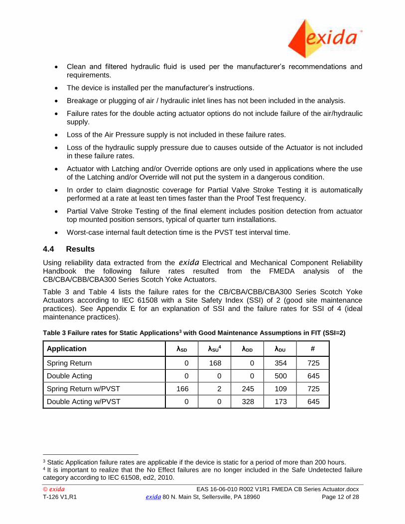
Table 3 and Table 4 lists the failure rates for the CB/CBA/CBB/CBA300 Series Scotch Yoke Actuators according to IEC 61508 with a Site Safety Index (SSI) of 2 (good site maintenance practices). See Appendix E for an explanation of SSI and the failure rates for SSI of 4 (ideal maintenance practices).
Table 3 Failure rates for Static Applications3 with Good Maintenance Assumptions in FIT (SSI=2)
Application λSD λSU4 λDD λDU #
Spring Return 0 168 0 354 725
Double Acting 0 0 0 500 645
Spring Return w/PVST 166 2 245 109 725
Double Acting w/PVST 0 0 328 173 645
3 Static Application failure rates are applicable if the device is static for a period of more than 200 hours. 4 It is important to realize that the No Effect failures are no longer included in the Safe Undetected failure category according to IEC 61508, ed2, 2010.
© exida EAS 16-06-010 R002 V1R1 FMEDA CB Series Actuator.docx
T-126 V1,R1 exida 80 N. Main St, Sellersville, PA 18960 Page 13 of 28
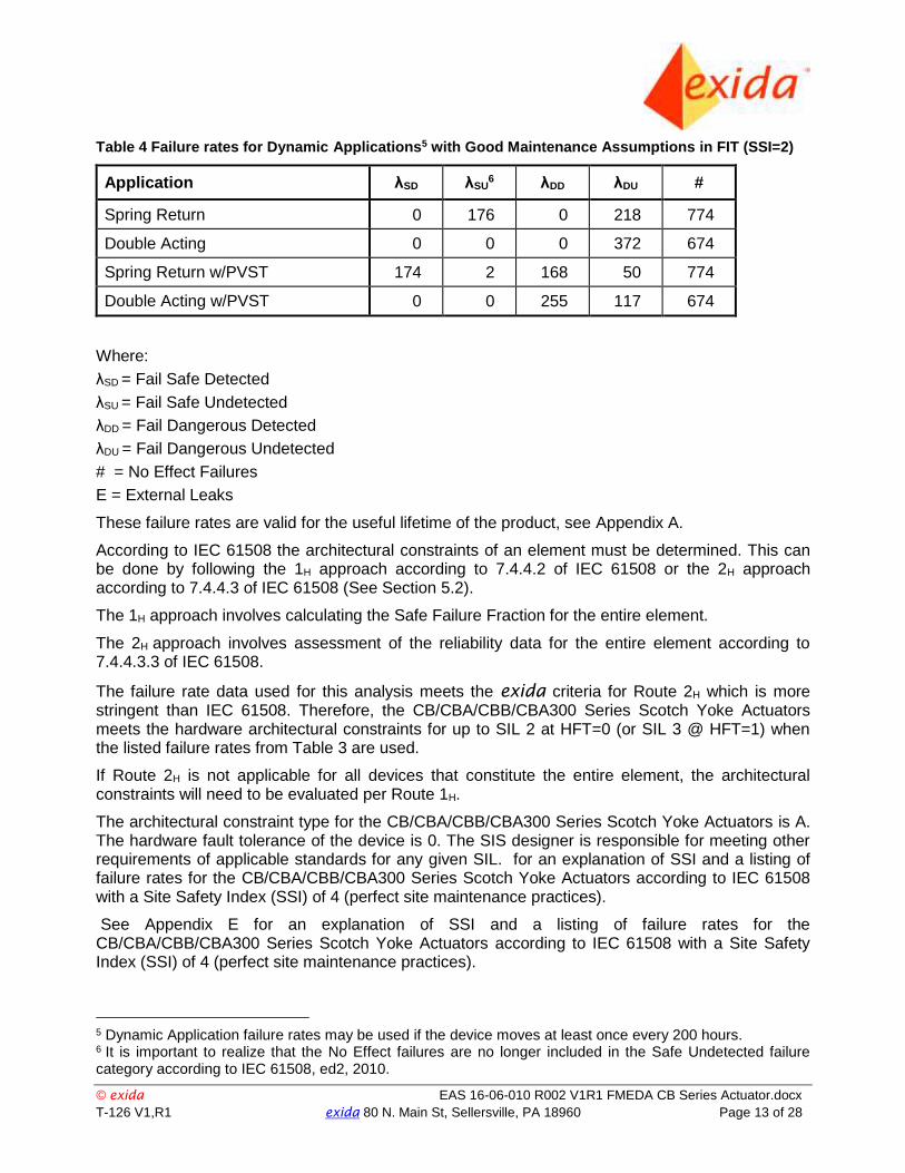
Table 4 Failure rates for Dynamic Applications5 with Good Maintenance Assumptions in FIT (SSI=2)
Application λSD λSU6 λDD λDU #
Spring Return 0 176 0 218 774
Double Acting 0 0 0 372 674
Spring Return w/PVST 174 2 168 50 774
Double Acting w/PVST 0 0 255 117 674
Where:
λSD = Fail Safe Detected
λSU = Fail Safe Undetected
λDD = Fail Dangerous Detected
λDU = Fail Dangerous Undetected
# = No Effect Failures
E = External Leaks
These failure rates are valid for the useful lifetime of the product, see Appendix A.
According to IEC 61508 the architectural constraints of an element must be determined. This can be done by following the 1H approach according to 7.4.4.2 of IEC 61508 or the 2H approach according to 7.4.4.3 of IEC 61508 (See Section 5.2).
The 1H approach involves calculating the Safe Failure Fraction for the entire element.
The 2H approach involves assessment of the reliability data for the entire element according to 7.4.4.3.3 of IEC 61508.
The failure rate data used for this analysis meets the exida criteria for Route 2H which is more stringent than IEC 61508. Therefore, the CB/CBA/CBB/CBA300 Series Scotch Yoke Actuators meets the hardware architectural constraints for up to SIL 2 at HFT=0 (or SIL 3 @ HFT=1) when the listed failure rates from Table 3 are used.
If Route 2H is not applicable for all devices that constitute the entire element, the architectural constraints will need to be evaluated per Route 1H.
The architectural constraint type for the CB/CBA/CBB/CBA300 Series Scotch Yoke Actuators is A. The hardware fault tolerance of the device is 0. The SIS designer is responsible for meeting other requirements of applicable standards for any given SIL. for an explanation of SSI and a listing of failure rates for the CB/CBA/CBB/CBA300 Series Scotch Yoke Actuators according to IEC 61508 with a Site Safety Index (SSI) of 4 (perfect site maintenance practices).
See Appendix E for an explanation of SSI and a listing of failure rates for the CB/CBA/CBB/CBA300 Series Scotch Yoke Actuators according to IEC 61508 with a Site Safety Index (SSI) of 4 (perfect site maintenance practices).
5 Dynamic Application failure rates may be used if the device moves at least once every 200 hours. 6 It is important to realize that the No Effect failures are no longer included in the Safe Undetected failure category according to IEC 61508, ed2, 2010.
© exida EAS 16-06-010 R002 V1R1 FMEDA CB Series Actuator.docx
T-126 V1,R1 exida 80 N. Main St, Sellersville, PA 18960 Page 14 of 28
5 Using the FMEDA Results
The following section(s) describe how to apply the results of the FMEDA.
5.1 PFDavg calculation CB/CBA/CBB/CBA300 Series Scotch Yoke Actuators
Using the failure rate data displayed in Table 3, section 4.4, and the failure rate data for the associated element devices, an average the Probability of Failure on Demand (PFDavg) calculation can be performed for the entire final element.
Probability of Failure on Demand (PFDavg) calculation uses several parameters, many of which are determined by the particular application and the operational policies of each site. Some parameters are product specific and the responsibility of the manufacturer. Those manufacturer specific parameters are given in this third party report.
Probability of Failure on Demand (PFDavg) calculation is the responsibility of the owner/operator of a process and is often delegated to the SIF designer. Product manufacturers can only provide a PFDavg by making many assumptions about the application and operational policies of a site which may be incorrect. Therefore, the use of pre-calculated PFDavg numbers requires complete knowledge of the assumptions and a match with the actual application and site.
Probability of Failure on Demand (PFDavg) calculation is best accomplished with exida’s exSILentia tool. See Appendix D for a complete description of how to determine the Safety Integrity Level for the final element. The mission time used for the calculation depends on the PFDavg target and the useful life of the product. The failure rates for all the devices in the final element and the proof test coverage for the final element are required to perform the PFDavg calculation. The proof test coverage for the suggested proof test and the dangerous failure rate after proof test for the CB/CBA/CBB/CBA300 Series Scotch Yoke Actuators are listed in Table 6. This is combined with the dangerous failure rates after proof test for other devices in the final element to establish the proof test coverage for the final element.
When performing Partial Valve Stroke Testing at regular intervals, the CB/CBA/CBB/CBA300 Series Scotch Yoke Actuators contributes less to the overall PFDavg of the Safety Instrumented Function.
5.2 exida Route 2H Criteria
IEC 61508, ed2, 2010 describes the Route 2H alternative to Route 1H architectural constraints. The standard states:
"based on data collected in accordance with published standards (e.g., IEC 60300-3-2: or ISO 14224); and, be evaluated according to
the amount of field feedback; and
the exercise of expert judgment; and when needed
the undertake of specific tests,
in order to estimate the average and the uncertainty level (e.g., the 90% confidence interval or the probability distribution) of each reliability parameter (e.g., failure rate) used in the calculations."
exida has interpreted this to mean not just a simple 90% confidence level in the uncertainty analysis, but a high confidence level in the entire data collection process. As IEC 61508, ed2, 2010
does not give detailed criteria for Route 2H, exida has established the following:
© exida EAS 16-06-010 R002 V1R1 FMEDA CB Series Actuator.docx
T-126 V1,R1 exida 80 N. Main St, Sellersville, PA 18960 Page 15 of 28
1. field unit operational hours of 100,000,000 per each component; and
2. a device and all of its components have been installed in the field for one year or more; and
3. operational hours are counted only when the data collection process has been audited for correctness and completeness; and
4. failure definitions, especially "random" vs. "systematic" are checked by exida; and
5. every component used in an FMEDA meets the above criteria.
This set of requirements is chosen to assure high integrity failure data suitable for safety integrity verification.
© exida EAS 16-06-010 R002 V1R1 FMEDA CB Series Actuator.docx
T-126 V1,R1 exida 80 N. Main St, Sellersville, PA 18960 Page 16 of 28
6 Terms and Definitions
Automatic Diagnostics Tests performed online internally by the device or, if specified, externally by another device without manual intervention.
Device A device is something that is part of an element; but, cannot perform an element safety function on its own.
Dynamic Applications The movement interval of the final element device is less than 200 hours. Movement may be accomplished by PVST, full stroke proof testing or a demand on the system.
exida criteria A conservative approach to arriving at failure rates suitable for use in hardware evaluations utilizing the 2H Route in IEC 61508-2.
Fault tolerance Ability of a functional unit to continue to perform a required function in the presence of faults or errors (IEC 61508-4, 3.6.3).
FIT Failure in Time (1x10⁻⁹ failures per hour)
FMEDA Failure Mode Effect and Diagnostic Analysis
HFT Hardware Fault Tolerance
High demand Mode Mode, where the demand interval for operation made on a safety-related system is less than twice the proof test interval.
Low demand mode Mode, where the demand interval for operation made on a safety-related system is greater than twice the proof test interval.
PFDavg Average Probability of Failure on Demand
PVST Partial Valve Stroke Test - It is assumed that Partial Valve Stroke Testing, when performed, is automatically performed at least an order of magnitude more frequently than the proof test; therefore, the test can be assumed an automatic diagnostic. Because of the automatic diagnostic assumption, the Partial Valve Stroke Testing also has an impact on the Safe Failure Fraction.
Random Capability The SIL limit imposed by the Architectural Constraints for each element.
Severe Service Condition that exists when material through the valve has abrasive particles, as opposed to Clean Service where these particles are absent.
SFF Safe Failure Fraction, summarizes the fraction of failures which lead to a safe state plus the fraction of failures which will be detected by automatic diagnostic measures and lead to a defined safety action.
SIF Safety Instrumented Function
SIL Safety Integrity Level
SIS Safety Instrumented System – Implementation of one or more Safety Instrumented Functions. A SIS is composed of any combination of sensor(s), logic solver(s), and final element(s).
© exida EAS 16-06-010 R002 V1R1 FMEDA CB Series Actuator.docx
T-126 V1,R1 exida 80 N. Main St, Sellersville, PA 18960 Page 17 of 28
SSI Site Safety Index (See Appendix E)
Static Applications The movement interval of the final element device is greater than 200 hours. Movement may be accomplished by PVST, full stroke proof testing or a demand on the system.
Type A element “Non-Complex” element (using discrete components); for details see 7.4.4.1.2 of IEC 61508-2
Type B element “Complex” element (using complex components such as micro controllers or programmable logic); for details see 7.4.4.1.3 of IEC 61508-2
© exida EAS 16-06-010 R002 V1R1 FMEDA CB Series Actuator.docx
T-126 V1,R1 exida 80 N. Main St, Sellersville, PA 18960 Page 18 of 28
7 Status of the Document
7.1 Liability
exida prepares FMEDA reports based on methods advocated in International standards. Failure rates are obtained from exida compiled field failure data and a collection of industrial databases.
exida accepts no liability whatsoever for the use of these numbers or for the correctness of the standards on which the general calculation methods are based.
Due to future potential changes in the standards, product design changes, best available information and best practices, the current FMEDA results presented in this report may not be fully consistent with results that would be presented for the identical model number product at some
future time. As a leader in the functional safety market place, exida is actively involved in evolving best practices prior to official release of updated standards so that our reports effectively anticipate any known changes. In addition, most changes are anticipated to be incremental in nature and results reported within the previous three-year period should be sufficient for current usage without significant question.
Most products also tend to undergo incremental changes over time. If an exida FMEDA has not been updated within the last three years, contact the product vendor to verify the current validity of the results.
7.2 Version History
Contract Number
Report Number Revision Notes
Q16/06-010 EAS 16/06-010 R002 V1, R1 Initial Release
Reviewer: Enter Reviewer Ted Stewart, exida, 10/31/2016 Status: Released, 11/1/2016
7.3 Future enhancements
At request of client.
7.4 Release signatures
Steven Close, Senior Safety Engineer
Ted Stewart, CFSP, Safety Engineer
© exida EAS 16-06-010 R002 V1R1 FMEDA CB Series Actuator.docx
T-126 V1,R1 exida 80 N. Main St, Sellersville, PA 18960 Page 19 of 28
Appendix A Lifetime of Critical Components
According to section 7.4.9.5 of IEC 61508-2, a useful lifetime, based on experience, should be assumed.
Although a constant failure rate is assumed by the probabilistic estimation method (see section 4.2.2) this only applies provided that the useful lifetime7 of components is not exceeded. Beyond their useful lifetime the result of the probabilistic calculation method is therefore meaningless, as the probability of failure significantly increases with time. The useful lifetime is highly dependent on the subsystem itself and its operating conditions.
This assumption of a constant failure rate is based on the bathtub curve. Therefore, it is obvious that the PFDavg calculation is only valid for components that have this constant domain and that the validity of the calculation is limited to the useful lifetime of each component.
It is the responsibility of the end user to maintain and operate the CB/CBA/CBB/CBA300 Series Scotch Yoke Actuators per manufacturer’s instructions. Furthermore, regular inspection should show that all components are clean and free from damage.
A major factor influencing the useful life is the air quality / quality of the hydraulic oil used.
Based on general field failure data a useful life period of approximately 20 years (actuators, valves, actuator-valve combinations) is expected for the CB/CBA/CBB/CBA300 Series Scotch Yoke Actuators.
When plant/site experience indicates a shorter useful lifetime than indicated in this appendix, the number based on plant/site experience should be used.
7 Useful lifetime is a reliability engineering term that describes the operational time interval where the failure rate of a device is relatively constant. It is not a term which covers product obsolescence, warranty, or other commercial issues.
© exida EAS 16-06-010 R002 V1R1 FMEDA CB Series Actuator.docx
T-126 V1,R1 exida 80 N. Main St, Sellersville, PA 18960 Page 20 of 28
Appendix B Proof Tests to Reveal Dangerous Undetected Faults
According to section 7.4.5.2 f) of IEC 61508-2 proof tests shall be undertaken to reveal dangerous faults which are undetected by automatic diagnostic tests. This means that it is necessary to specify how dangerous undetected faults which have been noted during the Failure Modes, Effects, and Diagnostic Analysis can be detected during proof testing.
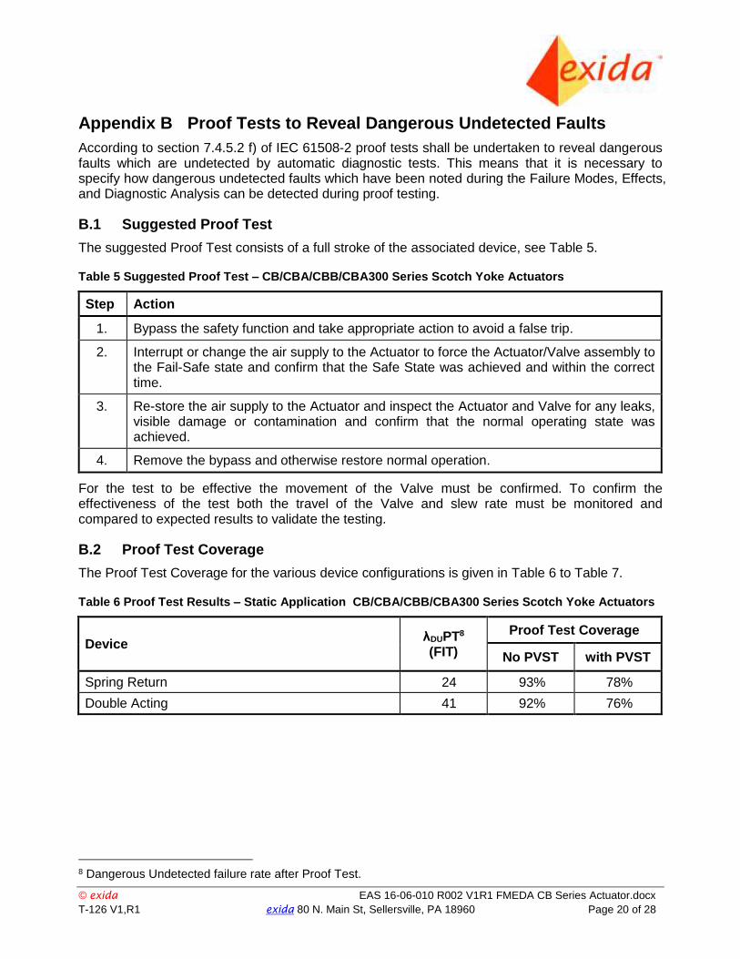
B.1 Suggested Proof Test
The suggested Proof Test consists of a full stroke of the associated device, see Table 5.
Table 5 Suggested Proof Test – CB/CBA/CBB/CBA300 Series Scotch Yoke Actuators
Step Action
1. Bypass the safety function and take appropriate action to avoid a false trip.
2. Interrupt or change the air supply to the Actuator to force the Actuator/Valve assembly to the Fail-Safe state and confirm that the Safe State was achieved and within the correct time.
3. Re-store the air supply to the Actuator and inspect the Actuator and Valve for any leaks, visible damage or contamination and confirm that the normal operating state was achieved.
4. Remove the bypass and otherwise restore normal operation.
For the test to be effective the movement of the Valve must be confirmed. To confirm the effectiveness of the test both the travel of the Valve and slew rate must be monitored and compared to expected results to validate the testing.
B.2 Proof Test Coverage
The Proof Test Coverage for the various device configurations is given in Table 6 to Table 7.
Table 6 Proof Test Results – Static Application CB/CBA/CBB/CBA300 Series Scotch Yoke Actuators
Device λDUPT8 (FIT)
Proof Test Coverage
No PVST with PVST
Spring Return 24 93% 78%
Double Acting 41 92% 76%
8 Dangerous Undetected failure rate after Proof Test.
© exida EAS 16-06-010 R002 V1R1 FMEDA CB Series Actuator.docx
T-126 V1,R1 exida 80 N. Main St, Sellersville, PA 18960 Page 21 of 28
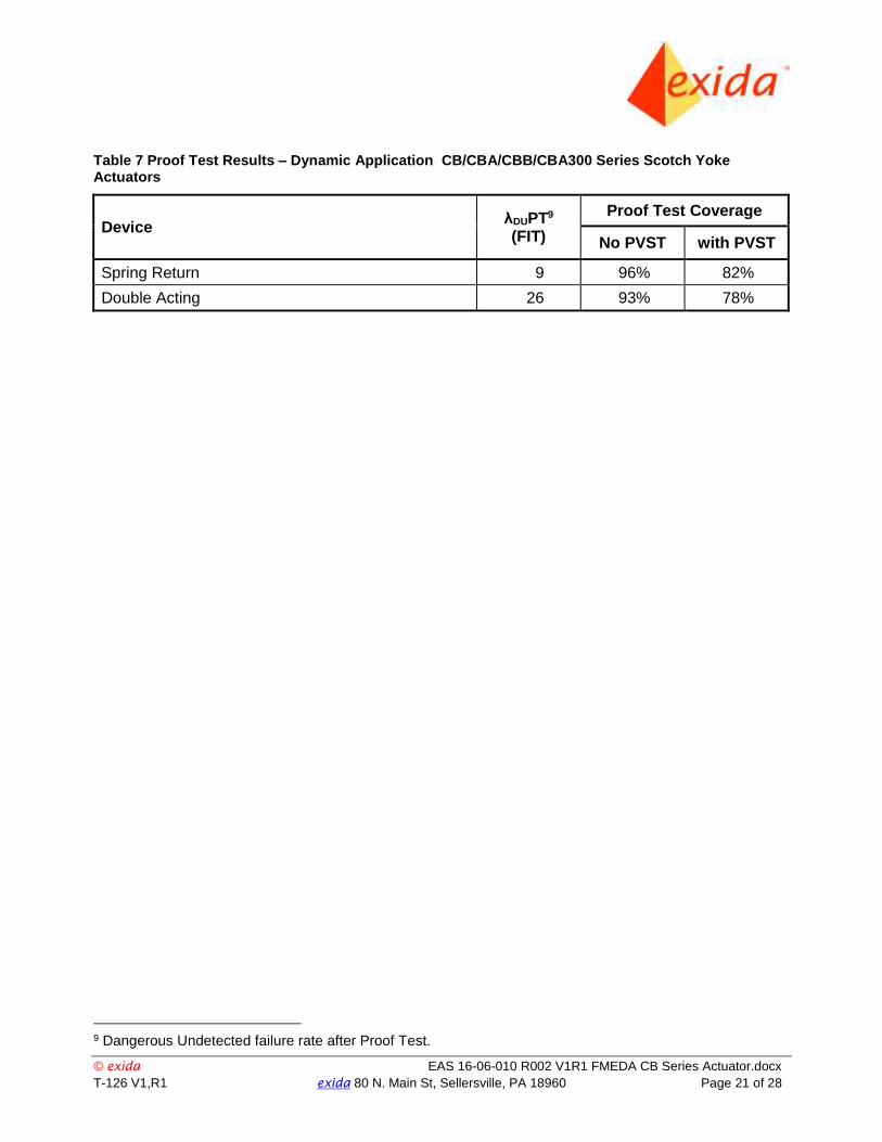
Table 7 Proof Test Results – Dynamic Application CB/CBA/CBB/CBA300 Series Scotch Yoke Actuators
Device λDUPT9 (FIT)
Proof Test Coverage
No PVST with PVST
Spring Return 9 96% 82%
Double Acting 26 93% 78%
9 Dangerous Undetected failure rate after Proof Test.
© exida EAS 16-06-010 R002 V1R1 FMEDA CB Series Actuator.docx
T-126 V1,R1 exida 80 N. Main St, Sellersville, PA 18960 Page 22 of 28
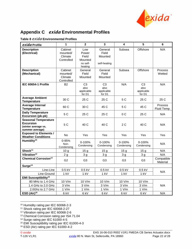
Appendix C exida Environmental Profiles
Table 8 exida Environmental Profiles
exida Profile 1 2 3 4 5 6
Description (Electrical)
Cabinet mounted/ Climate
Controlled
Low Power Field
Mounted
General Field
Mounted
Subsea Offshore N/A
no self-heating
self-heating
Description (Mechanical)
Cabinet mounted/ Climate
Controlled
General Field
Mounted
General Field
Mounted
Subsea Offshore Process Wetted
IEC 60654-1 Profile B2 C3 C3 N/A C3 N/A
also applicable
for D1
also applicable
for D1
also applicable
for D1
Average Ambient Temperature
30 C 25 C 25 C 5 C 25 C 25 C
Average Internal Temperature
60 C 30 C 45 C 5 C 45 C Process
Fluid Temp.
Daily Temperature Excursion (pk-pk)
5 C 25 C 25 C 0 C 25 C N/A
Seasonal Temperature Excursion (winter average vs. summer average)
5 C 40 C 40 C 2 C 40 C N/A
Exposed to Elements / Weather Conditions
No Yes Yes Yes Yes Yes
Humidity10 0-95% Non-
Condensing
0-100% Condensing
0-100% Condensing
0-100% Condensing
0-100% Condensing
N/A
Shock11 10 g 15 g 15 g 15 g 15 g N/A
Vibration12 2 g 3 g 3 g 3 g 3 g N/A
Chemical Corrosion13 G2 G3 G3 G3 G3
Compatible Material
Surge14
Line-Line 0.5 kV 0.5 kV 0.5 kV 0.5 kV 0.5 kV N/A
Line-Ground 1 kV 1 kV 1 kV 1 kV 1 kV
EMI Susceptibility15
80 MHz to 1.4 GHz 10 V/m 10 V/m 10 V/m 10 V/m 10 V/m
N/A 1.4 GHz to 2.0 GHz 3 V/m 3 V/m 3 V/m 3 V/m 3 V/m
2.0Ghz to 2.7 GHz 1 V/m 1 V/m 1 V/m 1 V/m 1 V/m
ESD (Air)16 6 kV 6 kV 6 kV 6 kV 6 kV N/A
10 Humidity rating per IEC 60068-2-3 11 Shock rating per IEC 60068-2-27 12 Vibration rating per IEC 60068-2-6 13 Chemical Corrosion rating per ISA 71.04 14 Surge rating per IEC 61000-4-5 15 EMI Susceptibility rating per IEC 61000-4-3 16 ESD (Air) rating per IEC 61000-4-2
© exida EAS 16-06-010 R002 V1R1 FMEDA CB Series Actuator.docx
T-126 V1,R1 exida 80 N. Main St, Sellersville, PA 18960 Page 23 of 28
Appendix D Determining Safety Integrity Level
The information in this appendix is intended to provide the method of determining the Safety Integrity Level (SIL) of a Safety Instrumented Function (SIF). The numbers used in the examples are not for the product described in this report.
Three things must be checked when verifying that a given Safety Instrumented Function (SIF) design meets a Safety Integrity Level (SIL) [N4] and [N7].
These are: A. Systematic Capability or Prior Use Justification for each device meets the SIL level of the SIF; B. Architecture Constraints (minimum redundancy requirements) are met; and C. a PFDavg calculation result is within the range of numbers given for the SIL level.
A. Systematic Capability (SC) is defined in IEC61508:2010. The SC rating is a measure of design quality based upon the methods and techniques used to design and development a product. All devices in a SIF must have a SC rating equal or greater than the SIL level of the SIF. For example, a SIF is designed to meet SIL 3 with three pressure transmitters in a 2oo3 voting scheme. The transmitters have an SC2 rating. The design does not meet SIL 3. Alternatively, IEC 61511 allows the end user to perform a "Prior Use" justification. The end user evaluates the equipment to a given SIL level, documents the evaluation and takes responsibility for the justification.
B. Architecture constraints require certain minimum levels of redundancy. Different tables show different levels of redundancy for each SIL level. A table is chosen and redundancy is incorporated into the design [N8].
C. Probability of Failure on Demand (PFDavg) calculation uses several parameters, many of which are determined by the particular application and the operational policies of each site. Some parameters are product specific and the responsibility of the manufacturer. Those manufacturer specific parameters are given in this third party report.
A Probability of Failure on Demand (PFDavg) must be done based on a number of variables including:
1. Failure rates of each product in the design including failure modes and any diagnostic coverage from automatic diagnostics (an attribute of the product given by this FMEDA report); 2. Redundancy of devices including common cause failures (an attribute of the SIF design); 3. Proof Test Intervals (assignable by end user practices); 4. Mean Time to Restore (an attribute of end user practices); 5. Proof Test Effectiveness; (an attribute of the proof test method used by the end user with an example given by this report); 6. Mission Time (an attribute of end user practices); 7. Proof Testing with process online or shutdown (an attribute of end user practices); 8. Proof Test Duration (an attribute of end user practices); and 9. Operational/Maintenance Capability (an attribute of end user practices).
The product manufacturer is responsible for the first variable. Most manufacturers use the exida FMEDA technique which is based on over 100 billion hours of field failure data in the process industries to predict these failure rates as seen in this report. A system designer chooses the second variable. All other variables are the responsibility of the end user site. The exSILentia® SILVerTM software considers all these variables and provides an effective means to calculate PFDavg for any given set of variables.
© exida EAS 16-06-010 R002 V1R1 FMEDA CB Series Actuator.docx
T-126 V1,R1 exida 80 N. Main St, Sellersville, PA 18960 Page 24 of 28
Simplified equations often account for only for first three variables. The equations published in IEC 61508-6, Annex B.3.2 [N1] cover only the first four variables. IEC61508-6 is only an informative portion of the standard and as such gives only concepts, examples and guidance based on the idealistic assumptions stated. These assumptions often result in optimistic PFDavg calculations and have indicated SIL levels higher than reality. Therefore, idealistic equations should not be used for actual SIF design verification.
All the variables listed above are important. As an example consider a high level protection SIF. The proposed design has a single SIL 3 certified level transmitter, a SIL 3 certified safety logic solver, and a single remote actuated valve consisting of a certified solenoid valve, certified scotch yoke actuator and a certified ball valve. Note that the numbers chosen are only an example and not the product described in this report.
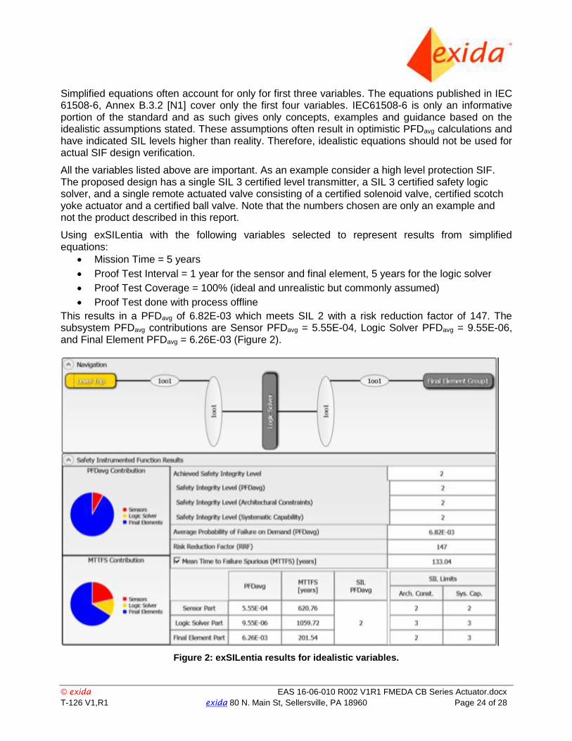
Using exSILentia with the following variables selected to represent results from simplified equations:
Mission Time = 5 years
Proof Test Interval = 1 year for the sensor and final element, 5 years for the logic solver
Proof Test Coverage = 100% (ideal and unrealistic but commonly assumed)
Proof Test done with process offline
This results in a PFDavg of 6.82E-03 which meets SIL 2 with a risk reduction factor of 147. The subsystem PFDavg contributions are Sensor PFDavg = 5.55E-04, Logic Solver PFDavg = 9.55E-06, and Final Element PFDavg = 6.26E-03 (Figure 2).
Figure 2: exSILentia results for idealistic variables.
© exida EAS 16-06-010 R002 V1R1 FMEDA CB Series Actuator.docx
T-126 V1,R1 exida 80 N. Main St, Sellersville, PA 18960 Page 25 of 28
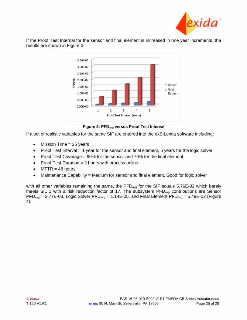
If the Proof Test Internal for the sensor and final element is increased in one year increments, the results are shown in Figure 3.
0.00E+00
5.00E-03
1.00E-02
1.50E-02
2.00E-02
2.50E-02
3.00E-02
3.50E-02
1 2 3 4 5
PFD
avg
Proof Test Interval (Years)
Series1
Series2
Sensor
Final Element
Figure 3: PFDavg versus Proof Test Interval
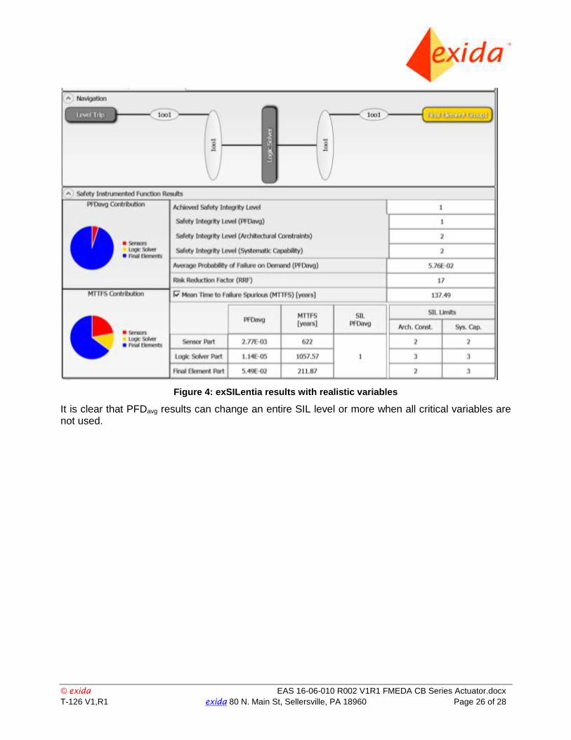
If a set of realistic variables for the same SIF are entered into the exSILentia software including:
Mission Time = 25 years
Proof Test Interval = 1 year for the sensor and final element, 5 years for the logic solver
Proof Test Coverage = 90% for the sensor and 70% for the final element
Proof Test Duration = 2 hours with process online.
MTTR = 48 hours
Maintenance Capability = Medium for sensor and final element, Good for logic solver
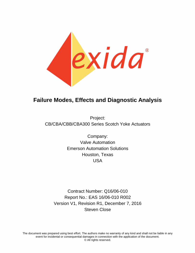
with all other variables remaining the same, the PFDavg for the SIF equals 5.76E-02 which barely meets SIL 1 with a risk reduction factor of 17. The subsystem PFDavg contributions are Sensor PFDavg = 2.77E-03, Logic Solver PFDavg = 1.14E-05, and Final Element PFDavg = 5.49E-02 (Figure 4).
© exida EAS 16-06-010 R002 V1R1 FMEDA CB Series Actuator.docx
T-126 V1,R1 exida 80 N. Main St, Sellersville, PA 18960 Page 26 of 28
Figure 4: exSILentia results with realistic variables
It is clear that PFDavg results can change an entire SIL level or more when all critical variables are not used.
© exida EAS 16-06-010 R002 V1R1 FMEDA CB Series Actuator.docx
T-126 V1,R1 exida 80 N. Main St, Sellersville, PA 18960 Page 27 of 28
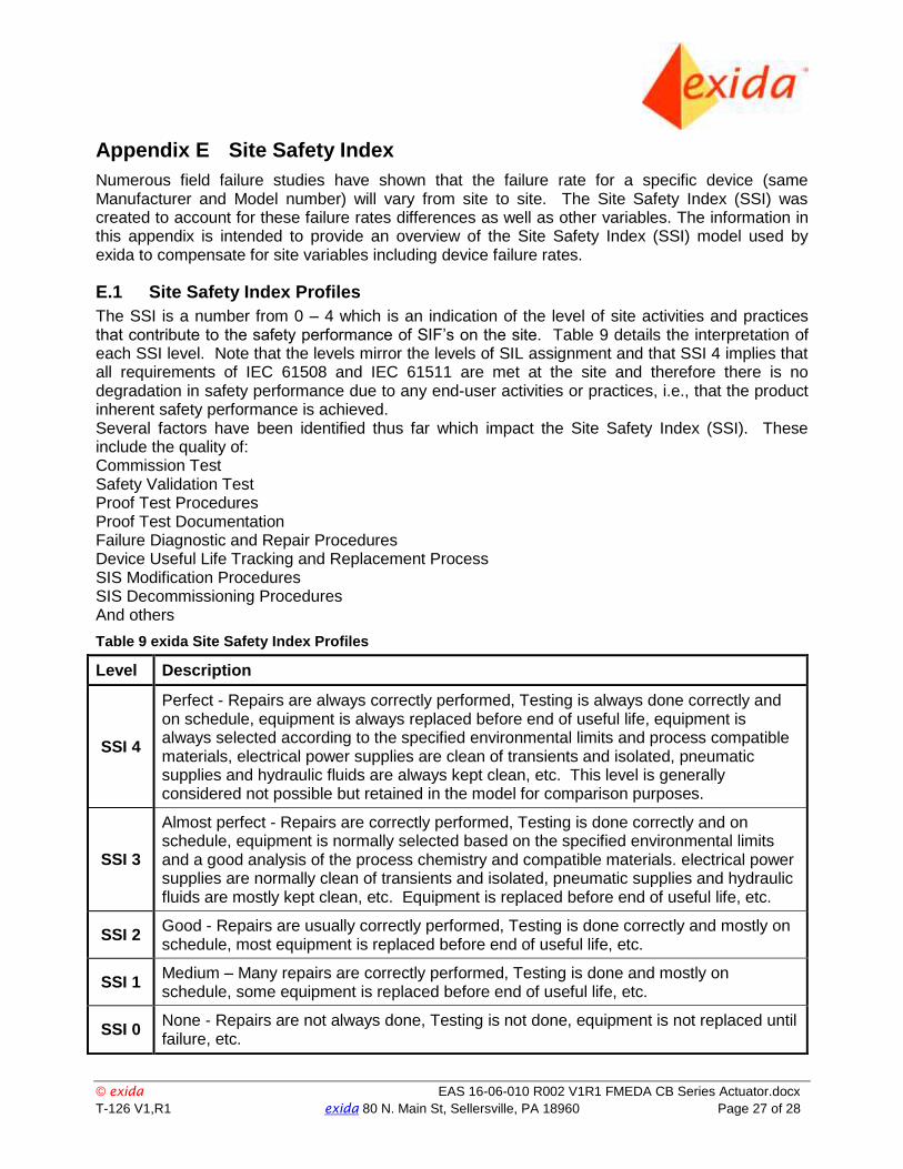
Appendix E Site Safety Index
Numerous field failure studies have shown that the failure rate for a specific device (same Manufacturer and Model number) will vary from site to site. The Site Safety Index (SSI) was created to account for these failure rates differences as well as other variables. The information in this appendix is intended to provide an overview of the Site Safety Index (SSI) model used by exida to compensate for site variables including device failure rates.
E.1 Site Safety Index Profiles
The SSI is a number from 0 – 4 which is an indication of the level of site activities and practices that contribute to the safety performance of SIF’s on the site. Table 9 details the interpretation of each SSI level. Note that the levels mirror the levels of SIL assignment and that SSI 4 implies that all requirements of IEC 61508 and IEC 61511 are met at the site and therefore there is no degradation in safety performance due to any end-user activities or practices, i.e., that the product inherent safety performance is achieved. Several factors have been identified thus far which impact the Site Safety Index (SSI). These include the quality of: Commission Test Safety Validation Test Proof Test Procedures Proof Test Documentation Failure Diagnostic and Repair Procedures Device Useful Life Tracking and Replacement Process SIS Modification Procedures SIS Decommissioning Procedures And others
Table 9 exida Site Safety Index Profiles
Level Description
SSI 4
Perfect - Repairs are always correctly performed, Testing is always done correctly and on schedule, equipment is always replaced before end of useful life, equipment is always selected according to the specified environmental limits and process compatible materials, electrical power supplies are clean of transients and isolated, pneumatic supplies and hydraulic fluids are always kept clean, etc. This level is generally considered not possible but retained in the model for comparison purposes.
SSI 3
Almost perfect - Repairs are correctly performed, Testing is done correctly and on schedule, equipment is normally selected based on the specified environmental limits and a good analysis of the process chemistry and compatible materials. electrical power supplies are normally clean of transients and isolated, pneumatic supplies and hydraulic fluids are mostly kept clean, etc. Equipment is replaced before end of useful life, etc.
SSI 2 Good - Repairs are usually correctly performed, Testing is done correctly and mostly on schedule, most equipment is replaced before end of useful life, etc.
SSI 1 Medium – Many repairs are correctly performed, Testing is done and mostly on schedule, some equipment is replaced before end of useful life, etc.
SSI 0 None - Repairs are not always done, Testing is not done, equipment is not replaced until failure, etc.
© exida EAS 16-06-010 R002 V1R1 FMEDA CB Series Actuator.docx
T-126 V1,R1 exida 80 N. Main St, Sellersville, PA 18960 Page 28 of 28
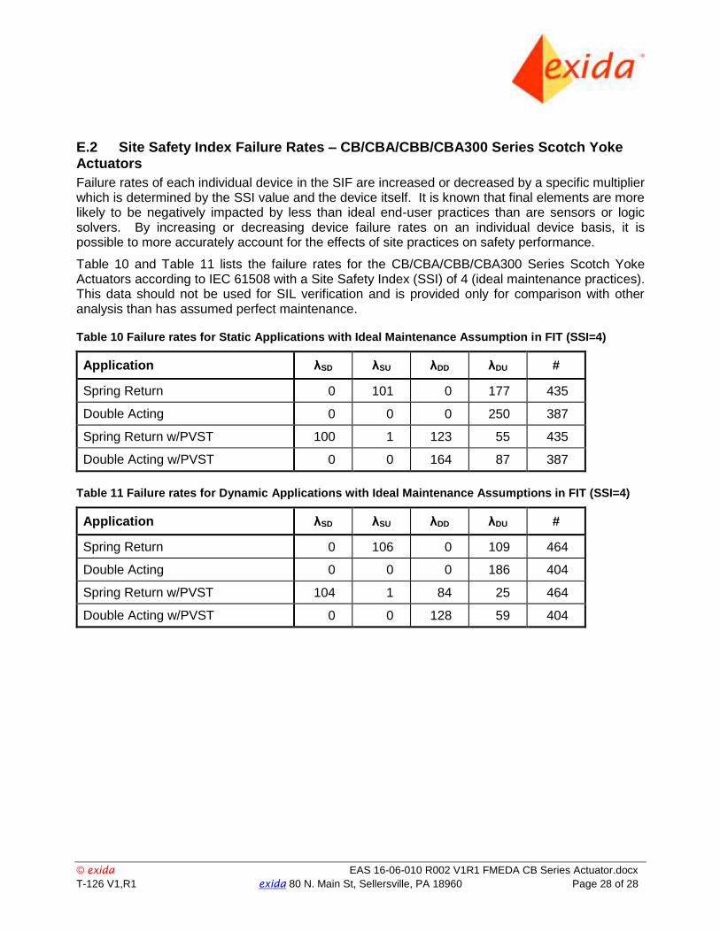
E.2 Site Safety Index Failure Rates – CB/CBA/CBB/CBA300 Series Scotch Yoke Actuators
Failure rates of each individual device in the SIF are increased or decreased by a specific multiplier which is determined by the SSI value and the device itself. It is known that final elements are more likely to be negatively impacted by less than ideal end-user practices than are sensors or logic solvers. By increasing or decreasing device failure rates on an individual device basis, it is possible to more accurately account for the effects of site practices on safety performance.
Table 10 and Table 11 lists the failure rates for the CB/CBA/CBB/CBA300 Series Scotch Yoke Actuators according to IEC 61508 with a Site Safety Index (SSI) of 4 (ideal maintenance practices). This data should not be used for SIL verification and is provided only for comparison with other analysis than has assumed perfect maintenance.
Table 10 Failure rates for Static Applications with Ideal Maintenance Assumption in FIT (SSI=4)
Application λSD λSU λDD λDU #
Spring Return 0 101 0 177 435
Double Acting 0 0 0 250 387
Spring Return w/PVST 100 1 123 55 435
Double Acting w/PVST 0 0 164 87 387
Table 11 Failure rates for Dynamic Applications with Ideal Maintenance Assumptions in FIT (SSI=4)
Application λSD λSU λDD λDU #
Spring Return 0 106 0 109 464
Double Acting 0 0 0 186 404
Spring Return w/PVST 104 1 84 25 464
Double Acting w/PVST 0 0 128 59 404