Embed Size (px)
Citation preview
Proceedings of6th International Fujaba Days
Uwe Aßmann, Jendrik Johannes,Albert Zundorf (Eds.)
Institut fur Software- und Multimediatechnik
TUD-FI08-09 September 2008
Technische BerichteTechnical Reports
ISSN 1430-211X
Fakultät Informatik
Technische Universität DresdenFakultät InformatikD−01062 DresdenGermanyURL: http://www.inf.tu−dresden.de/


Uwe Aßmann, Jendrik Johannes, Albert Zündorf (Eds.)
6th International Fujaba Days
Technische Universität Dresden, Germany September 18-19, 2008
Proceedings


Volume Editors Prof. Dr. Uwe Aßmann Technische Universität Dresden Departement of Computer Science Institute for Software and Multimedia Technologie Software Technologie Group Nöthnitzer Str. 46, 01187 Dresden, Germany [email protected] DIpl. Medieninf. Jendrik Johannes Technische Universität Dresden Departement of Computer Science Institute for Software and Multimedia Technologie Software Technologie Group Nöthnitzer Str. 46, 01187 Dresden, Germany [email protected] Prof. Dr. Albert Zündorf University of Kassel Chair of Research Group Software Engineering Department of Computer Science and Electrical Engineering Wilhelmshöher Allee 73, 34121 Kassel, Germany [email protected] Program Committee Program Committee Chairs Uwe Aßmann (TU Dresden, Germany) Albert Zündorf (University of Kassel, Germany) Program Commitee Members Uwe Aßmann (TU Dresden, Germany) Jürgen Börstler (University of Umea, Sweden) Gregor Engels (University of Paderborn, Germany) Holger Giese (University of Paderborn, Germany) Pieter van Gorp (University of Antwerp, Belgium) Jens Jahnke (University of Victoria, Canada) Mark Minas (University of the Federal Armed Forces, Germany) Manfred Nagl (RWTH Aachen, Germany) Andy Schürr (TU Darrmstadt, Germany) Wilhelm Schäfer (University of Paderborn, Germany) Gerd Wagner (University of Cottbus, Germany) Bernhard Westfechtel (University of Bayreuth, Germany) Albert Zündorf (University of Kassel, Germany)


Editor’s preface For more than ten years, Fujaba attracts a growing community of researchers in the field of software modelling. As its successful predecessors, the 6th International Fujaba Days offer a premises for Fujaba developers and users from all over the world to exchange experiences and drive Fujaba’s future development. The Software Technology Group of TU Dresden is active in the Fujaba community since 2005, sharing interests in areas such as UML and MOF modelling, OCL, and TGGs. Therefore, the group is proud to host the Fujaba Days 2008. 13 papers were received and accepted for the workshop after a careful reviewing process by the program committee. The papers are organized into four sections: Applications, Transforming and Debugging, Tool Integration, and Components. The variety of topics shows that there is a growing interest in using Fujaba in new areas of software modelling and in conjunction with other modelling tools and environments. We are convinced that this years Fujaba Days will give the opportunity to drive these ideas forward and enable new fruitful collaborations among the community. The PC chairs would like to thank the PC members for their careful work in reviewing the papers to ensure the quality of the Fujaba Days. Uwe Aßmann and Jendrik Johannes Organizers


Table of Contents
Applications Simple Robotics with Fujaba ..............................................................................................1
Ruben Jubeh and Albert Zuendorf (University of Kassel) Experiences with Modeling in the Large in Fujaba..............................................................5
Bernhard Westfechtel, Thomas Buchmann and Alexander Dotor (University of Bayreuth)
Fujaba goes Web 2.0 .......................................................................................................10 Nina Aschenbrenner, Jörn Dreyer, Ruben Jubeh and Albert Zuendorf (University of Kassel)
Transforming and Debugging Towards a Hybrid Transformation Language:
Implicit and Explicit Rule Scheduling in Story Diagrams ............................15 Bart Meyers and Pieter Van Gorp. (University of Antwerp)
Debugging Triple Graph Grammar-based Model Transformations ...................................19 Mirko Seifert and Stefan Katscher (Technische Universität Dresden)
Model Level Debugging with Fujaba.................................................................................23 Leif Geiger (University of Kassel)
Tool Integration Fujaba’s Future in the MDA Jungle –
Fully Integrating Fujaba and the Eclipse Modeling Framework? ................28 Basil Becker, Holger Giese, Stephan Hildebrandt and Andreas Seibel (Hasso Plattner Institut, Potsdam)
Letting EMF Tools Talk to Fujaba through Adapters.........................................................32 Jendrik Johannes (Technische Universität Dresden)
The Fujaba Automotive Tool Suite ...................................................................................36 Kahtan Alhawash, Toni Ceylan, Tobias Eckardt, Masud Fazal-Baqaie, Joel Greenyer, Christian Heinzemann, Stefan Henkler, Renate Ristov, Dietrich Travkin and Coni Yalcin (University of Paderborn)
Hybrid Model Checking with the FUJABA Real-Time Tool Suite.......................................40 Martin Hirsch, Stefan Henkler and Claudia Priesterjahn (University of Paderborn)
Components Component Story Diagrams in Fujaba4Eclipse ................................................................44
Jörg Holtmann and Matthias Tichy (University of Paderborn) Towards Software Product Line Testing using Story Driven Modeling ..............................48
Sebastian Oster, Andy Schürr and Ingo Weisemöller (University of Darmstadt) Integration of Legacy Components in MechatronicUML Architectures ..............................52
Christian Brenner, Stefan Henkler, Martin Hirsch, Claudia Priesterjahn (University of Paderborn) and Holger Giese (Hasso Plattner Institut, Potsdam)


Simple Robotics with Fujaba
Ruben Jubeh, Albert ZündorfUniversity of Kassel, Software Engineering,
Department of Computer Science and Electrical EngineeringWilhelmshöher Allee 7334121 Kassel, Germany
[ruben | zuendorf]@cs.uni-kassel.dehttp://www.se.eecs.uni-kassel.de/se/
ABSTRACTFujaba is not only used for professional software develop-ment but also for teaching software development. We haveused Fujaba successfully in our education efforts for a longtime. In order to give students a better experience andfeedback, we are preparing programming exercises with asimple robotic system. We are using the Lego MinstormsNXT robotics kit for that purpose. It consists of a micro-controller, motors, several sensors and of course, Lego partsto build different kinds of robots. The micro-controller canbe either remote controlled by a PC or run deployed soft-ware. This paper describes how we use Fujaba to develop asoftware which controls a simple forklift robot, which solvesthe Towers of Hanoi game.
1. INTRODUCTIONFujaba is used for teaching software development success-fully at Kassel University. In cooperation with the GaußschuleBraunschweig we developed a robot programming coursewith the predecessor product from Lego, the MindstormsRobotics Invention System, which was released in 1998. Al-though it was possible to control a Lego forklift robot withFujaba, the project faced lots of difficulties and obstacles.For example, the communication between the host PC andthe mindstorms microcontroller was done by a infrared link,which was slow and unreliable. Furthermore, it was diffi-cult to have more than one system in a room. More detailscan be found in [2]. Now we tried to use the newer LegoMindstorms NXT robotics system [4], released in 2006. Itprovides improved hardware: a full-featured 32bit micro-processor, step counter motors, graphical LCD display andUSB and bluetooth connectivity. The heart of the system,the so called NXT brick containing the micro-controller, canbe either remote controlled by a PC or run deployed soft-ware. Four sensors and three motors can be connected tothe brick.
Figure 1: Forklift robot
This paper describes how we use Fujaba to develop a soft-ware which controls a simple forklift robot. Section 2 de-scribes how we designed our forklift robot.
Figure 2: solve()-Method of Hanoi
At the practical side, our forklift robot should solve the Tow-ers of Hanoi game. This is a well documented mathematicalgame or puzzle which consists of three rods, and a number
1
of disks of different sizes which can slide onto any rod. Thepuzzle starts with the disks stacked in order of size on onerod, the smallest at the top, thus making a conical shape.The objective of the puzzle is to move the entire stack stepby step to another rod. Only one disk may be moved at atime. Each move consists of taking the top-most disk fromone of the rods and sliding it onto another rod, on top ofthe other disks that may already be present on that rod.No disk may be placed on top of a smaller disk. In our ap-proach, we replaced the disks by wooden blocks and don’tuse any rods. The blocks just get piled directly onto eachother. The recursive software solution is very simple, seeFigure 2. The solve()-method gets called recursively, trans-fer() simply moves the top disc from the source to the targetstack. [1] discusses this recursive solution in detail. To carrythat software solution into the real world, each time a discis moved, the robot should drive to that certain block, grabit, drive to the destination and discard the block.
To keep the control software separately from the concreteproblem, we decided to implement it as software library.Figure 3 shows the class diagram of our FujabaNxtLib, whichis a Fujaba project. The central class is FNXT which repre-sents the NXT Brick. The Motor class and the several kindsof Sensor classes are self explanatory. Each sensor class hasa corresponding listener interface (not shown). The classFNavigator controls the two driving motors and providesmethods for moving and turning the robot.
Figure 3: Class Diagram of the Fujaba NXT Library
2. THE ROBOT HARDWAREIt turned out that building the forklift itself was quite dif-ficult. Our early Lego models did not turn properly, were
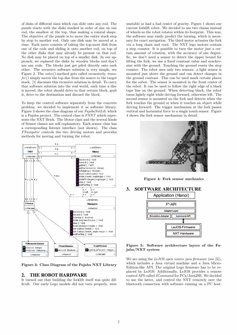
unstable or had a bad center of gravity. Figure 1 shows ourcurrent forklift robot. We decided to use two chains insteadof wheels so the robot rotates within its footprint. This way,the software may easily predict the turning, which is neces-sary for exact navigation. The third motor actuates the forkvia a long chain and cord. The NXT lego motors containa step counter: It is possible to turn the motor just a cer-tain amount of rotation, with the accuracy of one degree.So, we don’t need a sensor to detect the upper bound forlifting the fork, we use a fixed constant value and synchro-nize with the ground. Touching the ground resets the stepcounter. The robot uses only two sensors: a light sensor ismounted just above the ground and can detect changes inthe ground contrast. This can be used mark certain placesfor the robot. The sensor is mounted in the front center ofthe robot. It can be used to follow the right edge of a blacktape line on the ground: When detecting black, the robotturns lightly right while driving forward, otherwise left. Thesecond sensor is mounted on the fork and detects when thefork touches the ground or when it touches an object whiledriving forward. The trigger mechanism at the fork passesvertical and horizontal force to a single touch sensor. Figure4 shows the fork sensor mechanism in detail.
Figure 4: Fork sensor mechanics
3. SOFTWARE ARCHITECTURE
Figure 5: Software architecture layers of the Fu-jaba/NXT system
We are using the LeJOS open source java firmware (see [5]),which includes a Java virtual machine and a Java Micro-Edition-like API. The original Lego firmware has to be re-placed by LeJOS. Additionally, LeJOS provides a remotecontrol API called ICommand for PCs/Java2SE. We decidedto use the latter, and control the NXT remotely over thebluetooth connection with software running on a PC host.
2

The sensor software components from Lego don’t supportany listener callbacks on changes directly, it is just possibleto ask the sensors for their current value. So, we have toconstantly poll all sensors and create events when the sen-sor values change. This is necessary because the controllingsoftware, which runs on the host, needs to react quickly onevents, for example by stopping a motor. Polling the sensorstakes only 10-50ms each time, so the polling is performedperiodically at a fixed interval. Fortunately, this does notinterfere with any control commands. These is a radicalimprovement over the old Mindstorms system, which had apoll latency of 100-200ms per sensor.
We are planning to replace the poll mechanism by a eventnotifier running directly on the NXT’s micro-controller, whichcall their listeners by active communication from the brickto the host over the bluetooth connection.
Figure 5 shows the software layers of our architecture. Ontop is the concrete application model. It uses the F*-API,so classes like FNXT, FNavigator, FMotor, FSensor etc.Each F*-Object has a associated adapter instance, whicheither delegates the calls to the ICommand API (Part ofthe LeJOS package) or simulates the behavior. This is usedfor testing purposes. The ICommand API uses a bluetoothconnection and sends simple byte-array commands to theLeJOS firmware on the NXT brick. There the commandsare interpreted and mapped to hardware resources.
4. SOFTWARE USAGE AND MODELINGThe easiest way to use the Fujaba NXT Library is to start itin debug mode and use eDOBS to create the initial FXNTinstance. After that, the methods on the individual motorand sensor instances can be called interactively. Figure 6shows Eclipse/eDOBS running the library. On the left, youcan see the FNavigator methods. A call to travel() will makethe robot drive immediately and block until it finishes.
Figure 6: Eclipse/eDOBS running the Fujaba NXTLibrary
To model the application behavior, both Story or State Dia-grams are suitable. To simplify matters, we currently useonly story diagrams. Figure 7 shows an example. Themethod findInitialPlace() does not require any control flow,
thus it is modeled as just one story activity. However, thesingle activity itself contains multiple steps and concurrency:some methods (forward(), backward()) are asynchronous,that means the method call immediately returns, but therobot acts until a contrary method (stop() in that case)is called. After calling a asynchronous method, we use awaitFor-Some-Event-method, in this case waitForPressed()/waitForReleased() on the touch sensor instance. This is asimplification for easy modeling: instead of implementing alistener and being forced to handle the event in some otherplace of the model, this method blocks until an event of thedesired type occurs. This makes reactive programming a biteasier, but semantically means that the single activity is di-vided into two timing states: the robot drives forward untilthe sensor hits something, then backwards until the robot isfree again.
Figure 7: Example of a Hanoi method for findingthe blocks
5. PUTTING IT ALL TOGETHER: SOLV-ING HANOI
Figure 8 shows the class diagram of our Hanoi robot model.It consists of three Fujaba projects: The FujabaNxtLib pro-vides the FNXT, ForkLiftRobot and Fork, thus the abstractmodeling to control the hardware. The classes Place, Disc,Hanoi and Solver come from a abstract Hanoi project whichcan be run or debugged independently from any hardware.The HanoiRobot project, consisting of just HanoiProblemand RobotSolver, depends on the both projects and con-nects these. We just need to override Solver.transfer() andhook in concrete robot commands to move blocks aroundthere.
Our modeling of the robot-enabled transfer() method is justa reference, students will be given only the FujabaNxtLibLibrary and then should model their own solution.
6. SUMMARY AND FUTURE WORKWe used the new Lego Mindstorms robotics system to imple-ment a forklift robot which can solve the Towers of Hanoigame. The application model was implemented using Fu-jaba. It is easy to implement the robot control softwareusing standard Fujaba modeling techniques, which makes itsuitable for education. By using Fujaba project dependen-cies, we were able to develop a Library, so modeling control
3
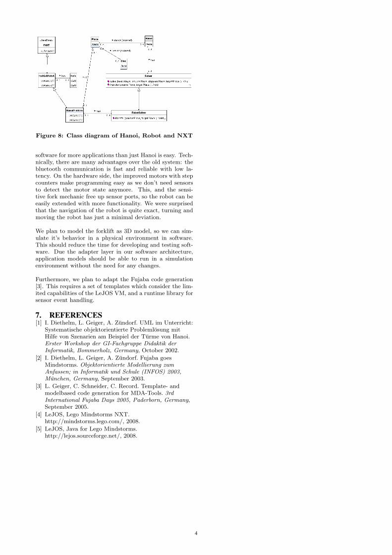
Figure 8: Class diagram of Hanoi, Robot and NXT
software for more applications than just Hanoi is easy. Tech-nically, there are many advantages over the old system: thebluetooth communication is fast and reliable with low la-tency. On the hardware side, the improved motors with stepcounters make programming easy as we don’t need sensorsto detect the motor state anymore. This, and the sensi-tive fork mechanic free up sensor ports, so the robot can beeasily extended with more functionality. We were surprisedthat the navigation of the robot is quite exact, turning andmoving the robot has just a minimal deviation.
We plan to model the forklift as 3D model, so we can sim-ulate it’s behavior in a physical environment in software.This should reduce the time for developing and testing soft-ware. Due the adapter layer in our software architecture,application models should be able to run in a simulationenvironment without the need for any changes.
Furthermore, we plan to adapt the Fujaba code generation[3]. This requires a set of templates which consider the lim-ited capabilities of the LeJOS VM, and a runtime library forsensor event handling.
7. REFERENCES[1] I. Diethelm, L. Geiger, A. Zundorf. UML im Unterricht:
Systematische objektorientierte Problemlosung mitHilfe von Szenarien am Beispiel der Turme von Hanoi.Erster Workshop der GI-Fachgruppe Didaktik derInformatik, Bommerholz, Germany, October 2002.
[2] I. Diethelm, L. Geiger, A. Zundorf. Fujaba goesMindstorms. Objektorientierte Modellierung zumAnfassen; in Informatik und Schule (INFOS) 2003,Munchen, Germany, September 2003.
[3] L. Geiger, C. Schneider, C. Record. Template- andmodelbased code generation for MDA-Tools. 3rdInternational Fujaba Days 2005, Paderborn, Germany,September 2005.
[4] LeJOS, Lego Mindstorms NXT.http://mindstorms.lego.com/, 2008.
[5] LeJOS, Java for Lego Mindstorms.http://lejos.sourceforge.net/, 2008.
4

Experiences with Modeling in the Large in Fujaba
Thomas BuchmannAngewandte Informatik 1
Universität BayreuthD-95440 Bayreuth
Alexander DotorAngewandte Informatik 1
Universität BayreuthD-95440 Bayreuth
Bernhard WestfechtelAngewandte Informatik 1
Universität BayreuthD-95440 Bayreuth
ABSTRACTModel-driven software development intends to reduce devel-opment effort by generating code from high-level models.However, models for non-trivial problems are still large andrequire sophisticated support for modeling in the large. Ex-periences from a recently launched project dedicated to amodel-driven modular SCM system confirm this claim. Thispaper investigates modeling in the large support provided bythe object-oriented CASE tool Fujaba and discusses poten-tial extensions of Fujaba based on UML package diagrams.
Categories and Subject DescriptorsD.2.11 [Software Engineering]: Software architectures—languages; D.2.11 [Software Engineering]: Management—software configuration management
Keywordsversion control, packages, imports
1. INTRODUCTIONSoftware configuration management (SCM) is the disci-
pline of controlling the evolution of large and complex soft-ware systems. A wide variety of SCM tools and systems hasbeen implemented, ranging from small tools such as RCS[10] over medium-sized systems such as CVS [11] or Subver-sion [4] to large-scale industrial systems such as ClearCase[12].
Version control is a core function of any SCM system.Version control is based on version models, many of whichhave been implemented in research prototypes, open sourceproducts, and commercial systems [5]. While there are con-siderable differences among these version models, it is alsotrue that similar concepts such as revisions, variants, state-and change-based versioning appear over and over again.Unfortunately, version models are usually implicitly con-tained in implemented systems.
Thus, the SCM domain is characterized by a large num-ber of systems with more or less similar features incorporat-ing hard-wired version models which have been implementedwith considerable effort. This observation has motivated usto set up a project dedicated to a model-driven modular SCMsystem (abbreviated as MOD2-SCM [2]):
First, version models are defined explicitly rather thanimplicitly in the code. This makes it easier to communicateand reason about version models. Second, modeling com-prises both structure and behavior. Furthermore, behavioralmodels are executable. Third, productivity is improved by
replacing programming with the creation of executable mod-els. Fourth, version models are not created from scratch.Rather, reuse is performed on the modeling level by follow-ing a product line approach [3]. Finally, the product line isbased on a model library which is composed of reusable andloosely coupled architectural units.
In MOD2-SCM, we decided to use the object-orientedmodeling language and environment Fujaba [15] because itsupports generation of executable (Java) code from a UMLmodel. To date, only a few approaches have been dedicatedto model-driven development of versioning systems [14, 13,7]. However, all of these approaches are confined to struc-tural models inasmuch as the behavior is hard-coded intothe respective system.
In this paper, we investigate modeling in the large withand beyond Fujaba. As to be demonstrated, the model cur-rently being developed in the MOD2-SCM project is fairlylarge. Furthermore, the success of the project heavily de-pends on a carefully designed model architecture with looselycoupled architectural units [2]: The product line should sup-port a set of variation points which may be combined in anorthogonal way as far as possible. To this end, the couplingbetween architectural units has to be reduced to a minimum.
2. MODELING IN THE LARGEIn object-oriented modeling, modeling in the large is an
area which has not attracted sufficient attention so far. Inthe following, we will first discuss support for modeling inthe large as far as it is provided in the current version of Fu-jaba. Subsequently, we will show how external tool supportmay be used to complement the functionality of Fujaba bycreating package diagrams from generated Java code. Fi-nally, we will discuss package diagrams in UML 2.0.
2.1 Support in Fujaba 5.1On a coarse-grained level, Fujaba models are organized
into projects. A project stores a model in a single file. Amodel stored as a project may be self-contained, or it mayreference models stored in external projects. These refer-ences imply dependencies between projects. In this way,both physical decomposition and model reuse are supported.
Within a project, model elements are created in diagrams.Class diagrams serve as the primary means for structuring.When a class is created, it may be assigned to a package inthe dialog window for class editing. Fujaba maintains a treeview of diagrams and model elements, but packages can beneither defined nor displayed in the tree view. Furthermore,Fujaba does not support package diagrams.
5
0..1
0..1
uses
0..n
0..1
«Virtual Path»
has versions
Iterator : ) (iteratorOfVersionsString : )Map:context, IProductModelItem:content (addVersion
IProductModelItem : )Map:context, String:vID (retrieveVersion
IVersionSet
«interface»
IVersionSet : ) (getVersionSetVoid : )Map:context, IProductModelItem:content (setContent
IProductModelItem : )Map:context (getContent
Void : )String:newID (setVersionID
String : ) (getVersionID
AbstractVersion
collapsed
IStorage
«interface»
Figure 1: Excerpt of a Fujaba class diagram
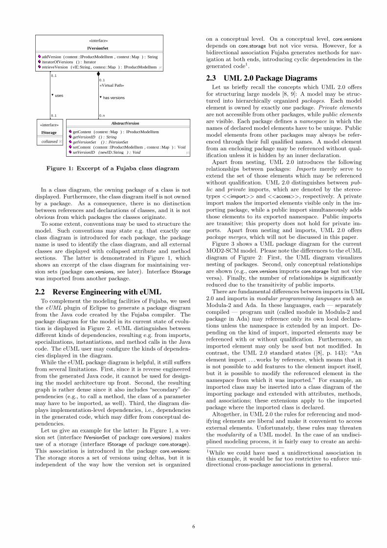
In a class diagram, the owning package of a class is notdisplayed. Furthermore, the class diagram itself is not ownedby a package. As a consequence, there is no distinctionbetween references and declarations of classes, and it is notobvious from which packages the classes originate.
To some extent, conventions may be used to structure themodel. Such conventions may state e.g. that exactly oneclass diagram is introduced for each package, the packagename is used to identify the class diagram, and all externalclasses are displayed with collapsed attribute and methodsections. The latter is demonstrated in Figure 1, whichshows an excerpt of the class diagram for maintaining ver-sion sets (package core.versions, see later). Interface IStorage
was imported from another package.
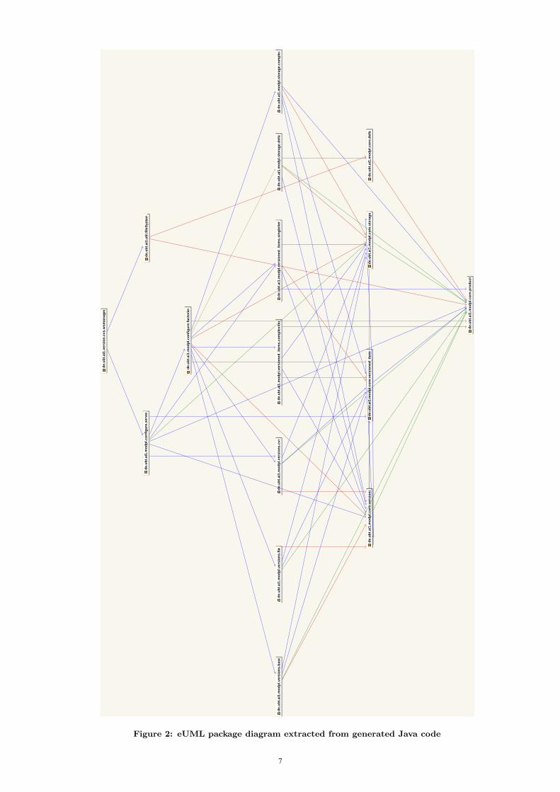
2.2 Reverse Engineering with eUMLTo complement the modeling facilities of Fujaba, we used
the eUML plugin of Eclipse to generate a package diagramfrom the Java code created by the Fujaba compiler. Thepackage diagram for the model in its current state of evolu-tion is displayed in Figure 2. eUML distinguishes betweendifferent kinds of dependencies, resulting e.g. from imports,specializations, instantiations, and method calls in the Javacode. The eUML user may configure the kinds of dependen-cies displayed in the diagram.
While the eUML package diagram is helpful, it still suffersfrom several limitations. First, since it is reverse engineeredfrom the generated Java code, it cannot be used for design-ing the model architecture up front. Second, the resultinggraph is rather dense since it also includes “secondary” de-pendencies (e.g., to call a method, the class of a parametermay have to be imported, as well). Third, the diagram dis-plays implementation-level dependencies, i.e., dependenciesin the generated code, which may differ from conceptual de-pendencies.
Let us give an example for the latter: In Figure 1, a ver-sion set (interface IVersionSet of package core.versions) makesuse of a storage (interface IStorage of package core.storage).This association is introduced in the package core.versions:The storage stores a set of versions using deltas, but it isindependent of the way how the version set is organized
on a conceptual level. On a conceptual level, core.versions
depends on core.storage but not vice versa. However, for abidirectional association Fujaba generates methods for nav-igation at both ends, introducing cyclic dependencies in thegenerated code1.
2.3 UML 2.0 Package DiagramsLet us briefly recall the concepts which UML 2.0 offers
for structuring large models [8, 9]: A model may be struc-tured into hierarchically organized packages. Each modelelement is owned by exactly one package. Private elementsare not accessible from other packages, while public elementsare visible. Each package defines a namespace in which thenames of declared model elements have to be unique. Publicmodel elements from other packages may always be refer-enced through their full qualified names. A model elementfrom an enclosing package may be referenced without qual-ification unless it is hidden by an inner declaration.
Apart from nesting, UML 2.0 introduces the followingrelationships between packages: Imports merely serve toextend the set of those elements which may be referencedwithout qualification. UML 2.0 distinguishes between pub-lic and private imports, which are denoted by the stereo-types <<import>> and <<access>>, respectively. A privateimport makes the imported elements visible only in the im-porting package, while a public import simultaneously addsthose elements to its exported namespace. Public importsare transitive; this property does not hold for private im-ports. Apart from nesting and imports, UML 2.0 offerspackage merges, which will not be discussed in this paper.
Figure 3 shows a UML package diagram for the currentMOD2-SCM model. Please note the differences to the eUMLdiagram of Figure 2: First, the UML diagram visualizesnesting of packages. Second, only conceptual relationshipsare shown (e.g., core.versions imports core.storage but not viceversa). Finally, the number of relationships is significantlyreduced due to the transitivity of public imports.
There are fundamental differences between imports in UML2.0 and imports in modular programming languages such asModula-2 and Ada. In these languages, each — separatelycompiled — program unit (called module in Modula-2 andpackage in Ada) may reference only its own local declara-tions unless the namespace is extended by an import. De-pending on the kind of import, imported elements may bereferenced with or without qualification. Furthermore, animported element may only be used but not modified. Incontrast, the UML 2.0 standard states ([8], p. 143): “Anelement import . . . works by reference, which means that itis not possible to add features to the element import itself,but it is possible to modify the referenced element in thenamespace from which it was imported.” For example, animported class may be inserted into a class diagram of theimporting package and extended with attributes, methods,and associations; these extensions apply to the importedpackage where the imported class is declared.
Altogether, in UML 2.0 the rules for referencing and mod-ifying elements are liberal and make it convenient to accessexternal elements. Unfortunately, these rules may threatenthe modularity of a UML model. In the case of an undisci-plined modeling process, it is fairly easy to create an archi-
1While we could have used a unidirectional association inthis example, it would be far too restrictive to enforce uni-directional cross-package associations in general.
6
de.u
bt.a
i1.m
odpl
.ver
sion
ed_i
tem
s.co
mpl
exite
mde
.ubt
.ai1
.mod
pl.v
ersi
ons.
flat
de.u
bt.a
i1.m
odpl
.cor
e.de
lta
de.u
bt.a
i1.m
odpl
.sto
rage
.com
plex
de.u
bt.a
i1.m
odpl
.ver
sion
s.cv
s
de.u
bt.a
i1.m
odpl
.con
figur
e.se
rver
de.u
bt.a
i1.m
odpl
.cor
e.ve
rsio
nsde
.ubt
.ai1
.mod
pl.c
ore.
stor
age
de.u
bt.a
i1.m
odpl
.cor
e.pr
oduc
t
de.u
bt.a
i1.m
odpl
.con
figur
e.fa
ctor
ies
de.u
bt.a
i1.m
odpl
.ver
sion
ed_i
tem
s.si
ngle
item
de.u
bt.a
i1.m
odpl
.ver
sion
s.ba
sede
.ubt
.ai1
.mod
pl.s
tora
ge.d
elta
de.u
bt.a
i1.u
til.fi
leSy
stem
de.u
bt.a
i1.m
odpl
.cor
e.ve
rsio
ned_
item
s
de.u
bt.a
i1.v
ersi
on.c
vs.w
sman
ager
Figure 2: eUML package diagram extracted from generated Java code
7

product
storage delta
«import»
«import»
core
versions
versioneditems
«import»
«import»
«import» «import» «import»
«import» «import»
versioned items
base
versions
flat cvs complex
storage
delta
«import»
complex item single item
«import»«import»
factories
«import» «import» «import» «import» «import» «import» «import»
server
«import»
configure
modpl
fileSystem
util
«import»
«import»
«import»
wsmanager
cvs
Figure 3: UML package diagram using nesting and public imports
8
tecture with tightly coupled packages — which would violatethe goals we pursue in the MOD2-SCM project.
In particular, there is no guarantee that a package dia-gram such as shown in Figure 3 shows the actual depen-dencies between packages in the architecture. First, it ispossible to reference external elements without imports byusing fully qualified names; the implied dependencies wouldnot be displayed in a package diagram showing only importrelationships. Second, public imports are transitive. Thus,when importing some package, all packages of the transi-tive closure of public imports are visible, as well. A packagediagram with public imports does not tell which of thesepackages are actually referenced.
For example, in Figure 3 the package configure.server im-ports configure.factories and thus may reference all packagesbelow. If the actual dependencies were so comprehensive,we would have to be concerned about the modularity of thesystem. Figure 2 shows that only a few dependencies em-anate from the server package. Still, there is one dependencyon the package versions.cvs which appears to be suspicious:Why should a configurable server depend on a specific ver-sion model such as the CVS model?
This example demonstrates that the package diagram withpublic imports appears to be elegant, but is too imprecise:There is no way around inspecting all actual dependenciesemanating from a package. To support such analyses, pri-vate imports would be more useful: As Java imports, privateimports are not transitive, forcing the client to explicitly im-port all packages on which it depends. Of course, privateimports imply a much denser diagram similar to the oneshown in Figure 2.
3. CONCLUSIONIn this paper, we reported on experiences with model-
ing in the large in Fujaba, referring to a recently launchedproject for developing a model-driven product line for SCMsystems. Our experiences indicate that reverse engineer-ing of the model architecture with an external tool is notsufficient and thus improved support for modeling in thelarge in Fujaba itself is urgently needed. We also discussedUML 2.0 package diagrams as a notation for model archi-tectures, focusing on package imports (the fairly complexconcept of package merge goes beyond the scope of this pa-per, see e.g. [6]). Please note that package diagrams areavailable in MOFLON [1], which has been built on top ofFujaba. However, MOFLON currently supports only pub-lic imports, while our experiences demonstrate that privateimports are needed, as well.
To conclude, we give a few suggestions for extending Fu-jaba with support for modeling in the large: First, the treeview should be revised such that it allows to define a packagehierarchy. Second, not only model elements such as classesand associations, but also class and story diagrams shouldbe assigned uniquely to one package. Third, a graphicaleditor for package diagrams should be offered (supportingnesting of packages as well as public and private imports).Fourth, model elements may be referenced only where theyare visible. In addition, we recommend to implement somerestrictions which deviate from the UML 2.0 standard: First,qualified references should be disallowed to avoid hidden de-pendencies. Second, it should be prohibited to modify im-ported elements.
4. REFERENCES[1] C. Amelunxen, A. Konigs, T. Rotschke, and A. Schurr.
MOFLON: A Standard-Compliant MetamodelingFramework with Graph Transformations. InA. Rensink and J. Warmer, editors, Model DrivenArchitecture - Foundations and Applications: SecondEuropean Conference, volume 4066 of LNCS, pages361–375, Heidelberg, 2006. Springer.
[2] T. Buchmann, A. Dotor, and B. Westfechtel.MOD2-SCM: Experiences with co-evolving modelswhen designing a modular SCM system. InProceedings of the 1st International Workshop onModel Co-Evolution and Consistency Management,Toulouse, France, Oct. 2008.
[3] P. Clements and L. Northrop. Software Product Lines:Practices and Patterns. SEI Series in SoftwareEngineering. Addison-Wesley, Boston, Massachusetts,2005.
[4] B. Collins-Sussman, B. W. Fitzpatrick, and C. M.Pilato. Version Control with Subversion. O’Reilly &Associates, Sebastopol, California, 2004.
[5] R. Conradi and B. Westfechtel. Version models forsoftware configuration management. ACM ComputingSurveys, 30(2):232–282, June 1998.
[6] J. Dingel, Z. Diskin, and A. Zito. Understanding andimproving UML package merge. Software and SystemsModeling, Dec. 2007. Online First.
[7] J. Kovse. Model-Driven Development of VersioningSystems. PhD thesis, University of Kaiserslautern,Kaiserslautern, Germany, Aug. 2005.
[8] Object Management Group, Needham, Massachusetts.OMG Unified Modeling Language (OMG UML),Infrastructure, V 2.1.2, formal/2007-11-04 edition,Nov. 2007.
[9] Object Management Group, Needham, Massachusetts.OMG Unified Modeling Language (OMG UML),Superstructure, V 2.1.2, formal/2007-11-02 edition,Nov. 2007.
[10] W. F. Tichy. RCS – A system for version control.Software: Practice and Experience, 15(7):637–654,July 1985.
[11] J. Vesperman. Essential CVS. O’Reilly & Associates,Sebastopol, California, 2006.
[12] B. A. White. Software Configuration ManagementStrategies and Rational ClearCase. Object TechnologySeries. Addison-Wesley, Reading, Massachusetts, 2003.
[13] E. J. Whitehead, G. Ge, and K. Pan. Automaticgeneration of hypertext system repositories: a modeldriven approach. In 15th ACM Conference onHypertext and Hypermedia, pages 205–214, SantaCruz, CA, Aug. 2004. ACM Press.
[14] E. J. Whitehead and D. Gordon. Uniform comparisonof configuration management data models. InB. Westfechtel and A. van der Hoek, editors, SoftwareConfiguration Management: ICSE Workshops SCM2001 and SCM 2003, volume 2649 of LNCS, pages70–85. Springer, 2003.
[15] A. Zundorf. Rigorous object oriented softwaredevelopment. Technical report, University ofPaderborn, Germany, 2001.
9

Fujaba goes Web 2.0
Nina Aschenbrenner, Jörn Dreyer, Ruben Jubeh, Albert ZündorfUniversity of Kassel, Software Engineering,
Department of Computer Science and Electrical Engineering,Wilhelmshöher Allee 73,34121 Kassel, Germany
[nina.aschenbrenner | jdr | ruben | zuendorf]@cs.uni-kassel.dehttp://www.se.eecs.uni-kassel.de/se/
ABSTRACTThe latest research activities of the Fujaba group of KasselUniversity led to challenges in development of new web tech-nologies enabling end users to wrap services into web gad-gets and to combine them into complex web applications.Web applications running inside a webbrowser bring newrequirements to the traditional desktop application devel-opment process. Since web applications usually don’t cometo life using model based approaches or Story Driven Mod-elling the Fujaba Toolsuite has to be adopted to fulfil thenew requirements.
The Fujaba group of Kassel wanted to get all the help weare used to get from Fujaba in ordinary application develop-ment for our web applications, too. Thus, we are developinga new code generation for the generation of Google WebToolkit compliant Java code that will then be compiled intoJavaScript running on web browsers. In addition, we developtool support for building the GUIs of such web applications.And, on the server side, we develop technologies to facilitateservice development with Fujaba. This paper reports on thedesign of these new Fujaba web components.
1. INTRODUCTIONSince March 2008 the Fujaba group at Kassel University
participates in the European Project FAST: Fast and Ad-vanced Storyboard Tools. This project aims at the develop-ment of a new visual programming language and tools thatwill facilitate the development of complex front-end gad-gets. A gadget in this opinion is a small web applicationthat is designed to run inside a so called mashup platform.Some of these platforms like Yahoo Pipes[9], iGoogle[6] orMicrosofts Popfly[8] are widely used in the present. Sinceone of the project partners has already devolped a mashupplatform, the so called EzWeb platform [3], the Fujaba teamat Kassel tries to support gadgets for this platform at firstand focuses its research on the specific needs of EzWeb webgadgets. Since Kassel sees gadgets as kind of web applica-tion, the research regarding Fujaba and the development ofweb applications with Fujaba is not only focused on gadgetsneeded for FAST, but on what we call Web 2.0 applicationsin general. These applications and their development differfrom the standard desktop applications known to be gen-erated with Fujaba. There are many challenges that haveto be addressed to get applications running over the web inthe way we want them to. The main problem is the lackof possibilities you have on the client. Since the applica-tions are intended to run inside a web browser the clientside has to be JavaScript. The old way of web applica-
tions were web formulars on client side which communicatewith the server and are completely blocked while waiting forserver responses. Web 2.0 applications in our manner willbe Ajax applications, meaning that the whole communica-tion between client and server will be asynchronous givingthe user possibilities to interact with the application evenwhen waiting for server responses. Another problem youhave in the development of web applications is the distribu-tion of data, or more specifically replication of data modelsbetween the server and one or multiple clients. In the do-main of web applications developing client side code is doneby hand coding JavaScript for the browser. The Fujabateam at Kassel wanted to have all the opportunities knownfrom standard software development processes: code gener-ation, model based development and story driven modellingto benefit the development of web applications and gadgets.Thus, we chose to adapt Fujaba and its tools to suffice thenew needs.
Figure 1 shows the architecture of what we call Web 2.0application. On the client side a web browser may showsome web gadgets. We propose to program these web gad-gets as model view controller patterns, i.e. to separate therepresentation and the data model. The representation mayemploy some domain object model of the web page shown tothe user. Note, our reference architecture for Web 2.0 appli-cations is somewhat unconventional. Usually, the client hasonly view data and the server has the model data and theapplication logic. In our reference architecture, the applica-tion logic, i.e the business rules and model transformationsare to a large extent executed on the web clients based on themodel data available on that client. For GUI operations wedevelop a dedicated version of Fujaba Story Diagrams thatwill provide DOM rewrite rules within concrete syntax, cf.section 2. The application logic is based on an applicationdata model. This application data model and its operationmay be developed with usual Fujaba story diagrams. In or-der to deploy the resulting Java code on a web browser, wewill use Google Web Toolkit technology [4], cf. section 3.Synchronization between DOM and application data modelis done via the usual property change based event mecha-nisms.
For the development of (web) services we will use stan-dard Story Driven Modeling technologies. Note, some ser-vice models and some application models may overlap. Inthese cases, we develop the data model only once and deployit on client and on server side, equally. For certain applica-tions it may suffice to copy (parts of) the server data to theclient where the data is visualized and exploited using the
10
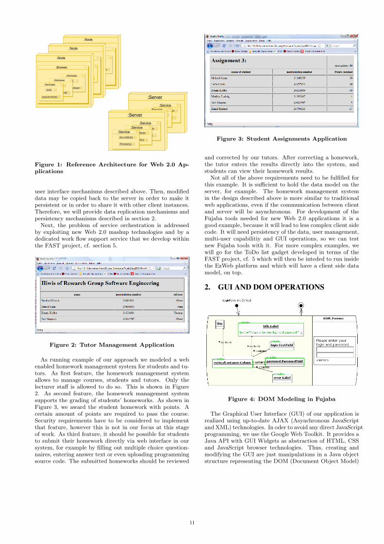
Figure 1: Reference Architecture for Web 2.0 Ap-plications
user interface mechanisms described above. Then, modifieddata may be copied back to the server in order to make itpersistent or in order to share it with other client instances.Therefore, we will provide data replication mechanisms andpersistency mechanisms described in section 2.
Next, the problem of service orchestration is addressedby exploiting new Web 2.0 mashup technologies and by adedicated work flow support service that we develop withinthe FAST project, cf. section 5.
Figure 2: Tutor Management Application
As running example of our approach we modeled a webenabled homework management system for students and tu-tors. As first feature, the homework management systemallows to manage courses, students and tutors. Only thelecturer staff is allowed to do so. This is shown in Figure2. As second feature, the homework management systemsupports the grading of students’ homeworks. As shown inFigure 3, we award the student homework with points. Acertain amount of points are required to pass the course.Security requirements have to be considered to implementthat feature, however this is not in our focus at this stageof work. As third feature, it should be possible for studentsto submit their homework directly via web interface in oursystem, for example by filling out multiple choice question-naires, entering answer text or even uploading programmingsource code. The submitted homeworks should be reviewed
Figure 3: Student Assignments Application
and corrected by our tutors. After correcting a homework,the tutor enters the results directly into the system, andstudents can view their homework results.
Not all of the above requirements need to be fulfilled forthis example. It is sufficient to hold the data model on theserver, for example. The homework management systemin the design described above is more similar to traditionalweb applications, even if the communication between clientand server will be asynchronous. For development of theFujaba tools needed for new Web 2.0 applications it is agood example, because it will lead to less complex client sidecode. It will need persistency of the data, user management,multi-user capabilitiy and GUI operations, so we can testnew Fujaba tools with it. For more complex examples, wewill go for the ToDo list gadget developed in terms of theFAST project, cf. 5 which will then be inteded to run insidethe EzWeb platform and which will have a client side datamodel, on top.
2. GUI AND DOM OPERATIONS
Figure 4: DOM Modeling in Fujaba
The Graphical User Interface (GUI) of our application isrealized using up-to-date AJAX (Asynchronous JavaScriptand XML) technologies. In oder to avoid any direct JavaScriptprogramming, we use the Google Web Toolkit. It provides aJava API with GUI Widgets as abstraction of HTML, CSSand JavaScript browser technologies. Thus, creating andmodifying the GUI are just manipulations in a Java objectstructure representing the DOM (Document Object Model)
11
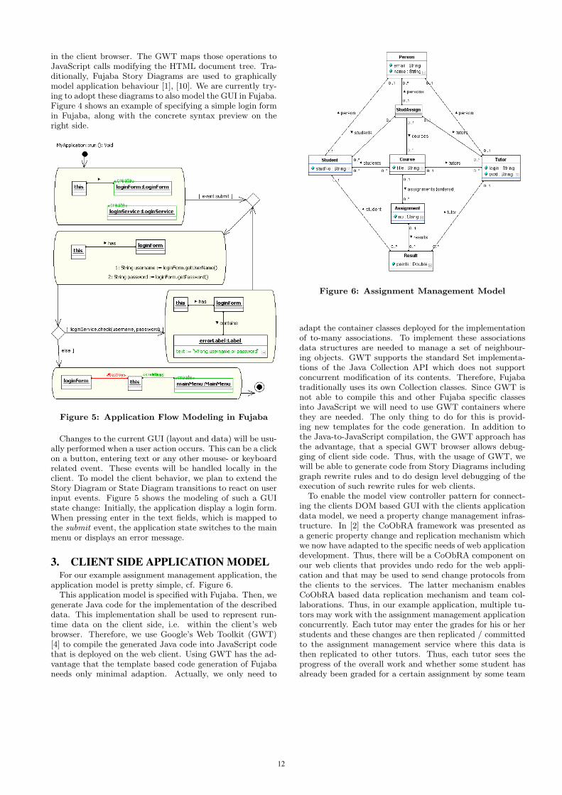
in the client browser. The GWT maps those operations toJavaScript calls modifying the HTML document tree. Tra-ditionally, Fujaba Story Diagrams are used to graphicallymodel application behaviour [1], [10]. We are currently try-ing to adopt these diagrams to also model the GUI in Fujaba.Figure 4 shows an example of specifying a simple login formin Fujaba, along with the concrete syntax preview on theright side.
Figure 5: Application Flow Modeling in Fujaba
Changes to the current GUI (layout and data) will be usu-ally performed when a user action occurs. This can be a clickon a button, entering text or any other mouse- or keyboardrelated event. These events will be handled locally in theclient. To model the client behavior, we plan to extend theStory Diagram or State Diagram transitions to react on userinput events. Figure 5 shows the modeling of such a GUIstate change: Initially, the application display a login form.When pressing enter in the text fields, which is mapped tothe submit event, the application state switches to the mainmenu or displays an error message.
3. CLIENT SIDE APPLICATION MODELFor our example assignment management application, the
application model is pretty simple, cf. Figure 6.This application model is specified with Fujaba. Then, we
generate Java code for the implementation of the describeddata. This implementation shall be used to represent run-time data on the client side, i.e. within the client’s webbrowser. Therefore, we use Google’s Web Toolkit (GWT)[4] to compile the generated Java code into JavaScript codethat is deployed on the web client. Using GWT has the ad-vantage that the template based code generation of Fujabaneeds only minimal adaption. Actually, we only need to
Figure 6: Assignment Management Model
adapt the container classes deployed for the implementationof to-many associations. To implement these associationsdata structures are needed to manage a set of neighbour-ing objects. GWT supports the standard Set implementa-tions of the Java Collection API which does not supportconcurrent modification of its contents. Therefore, Fujabatraditionally uses its own Collection classes. Since GWT isnot able to compile this and other Fujaba specific classesinto JavaScript we will need to use GWT containers wherethey are needed. The only thing to do for this is provid-ing new templates for the code generation. In addition tothe Java-to-JavaScript compilation, the GWT approach hasthe advantage, that a special GWT browser allows debug-ging of client side code. Thus, with the usage of GWT, wewill be able to generate code from Story Diagrams includinggraph rewrite rules and to do design level debugging of theexecution of such rewrite rules for web clients.
To enable the model view controller pattern for connect-ing the clients DOM based GUI with the clients applicationdata model, we need a property change management infras-tructure. In [2] the CoObRA framework was presented asa generic property change and replication mechanism whichwe now have adapted to the specific needs of web applicationdevelopment. Thus, there will be a CoObRA component onour web clients that provides undo redo for the web appli-cation and that may be used to send change protocols fromthe clients to the services. The latter mechanism enablesCoObRA based data replication mechanism and team col-laborations. Thus, in our example application, multiple tu-tors may work with the assignment management applicationconcurrently. Each tutor may enter the grades for his or herstudents and these changes are then replicated / committedto the assignment management service where this data isthen replicated to other tutors. Thus, each tutor sees theprogress of the overall work and whether some student hasalready been graded for a certain assignment by some team
12
mate.The infrastructure for property changes and for CoObRA
like change protocols are current work.
4. SERVICE DEVELOPMENTOn the server side, we deploy a server data model and
a persistency component. In simple cases the server datamodel is the same data model as the application data model.This will e.g. hold for our assignment management serviceand for our tutor management service. This data model isgenerated from the same Fujaba model that is used for thegeneration of the application data model. As can be seenfrom our reference architecture, the client can have applica-tion logic and data model, too. However, in some applica-tions, the client may load only a certain part of the wholedata, e.g. for performance or security reasons. In this casesome operations that require access to the whole data stor-age may be deployed on server side. In addition, the serverneeds to manage which clients are currently online and whichclient has loaded which part of the overall data. In case ofa data update the server has to compute which clients havereplicas of the corresponding data fragments and thus re-quire an update notification.
In general, the server component needs to provide somesupport for the access protocols used to communicate withthe web clients e.g. a simple object access mechanism.
In addition, the server needs a persistency component inorder to store data e.g. for recovery purposes. Here we usethe standard CoObRA mechanisms. Note, these CoObRAmechanisms allow direct storage of each change for recoveryas well as a transaction concept grouping change sets forconsistency purpose as well as a cvs like update / commitusage.
Using these mechanisms, the generation of simple (datareplication) services becomes quite simple. Just generateit from the Fujaba model. However, note that such serviceshave a certain scaling problem. CoObRA based applications/ services keep the whole runtime data in main memory andare thus restricted to data model sizes that fit into 2 gigabytemain memory on 32 bit Java virtual machines. This shouldnot easily become a problem for our assignment service orfor the tutor service. However, one would not run a bankingservice or a web shop on this limited data size. To over-come this scaling problem, we think of a combination of aCoObRA mechanism coordinating the data replication anda relational database for management of large data volumes.This is future work.
5. SERVICE ORCHESTRATIONAs mentioned before, within the FAST EU project the
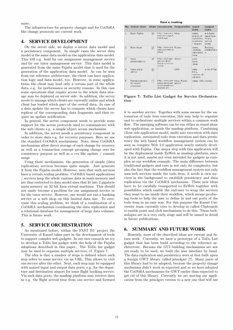
University of Kassel takes part in the development of toolsto support complex web gadgets. In our own research we tryto develop a ToDo list gadget with the help of the Fujabaadoptions described in this paper. The ToDo list gadgetmay be used to organize multiple services, cf. Figure 7.
The idea is that a number of steps is defined where eachstep refers to some service via an URL. This allows to visitone service after the other. Next, each step may be equippedwith named input and output data ports, e.g. for the depar-ture and destination airport for some flight booking service.Via such data ports, the mashup platform may retrieve dataas e.g. the flight arrival time from one service and forward
Figure 7: ToDo List Gadget for Service Orchestra-tion
it to another service. Together with some means for the au-tomation of todo item execution, this may help to organizeand to orchestrate multiple services within a common workflow. The emerging software can be run either as stand aloneweb application, or inside the mashup platform. Combiningclient side application model, multi user execution with datareplication, automated todo item execution and data persis-tency the web based workflow management system can beseen as complex Web 2.0 application nearly entirely devel-oped with Fujaba. One major step with this application willbe the deployment inside EzWeb as mashup platform, sinceit is not used, maybe not even intended for gadgets as com-plex as our workflow example. The main difference betweentraditional gadgets and ours is not only its complexity, butalso the fact that the workflow management system not onlyuses web services inside the todo item, it needs is own ser-vices in the background to establish persistency and datareplication via the CoObRA mechanism. These new ideashave to be carafully transported to EzWeb together withpossibilites which enable the end-user to wrap the servicesthey want to use inside their workflow, which means produc-ing tools to help the user to define in and out ports of thetodo item in an easy way. For this purpose the Kassel Uni-versity team currently tries to develop so called Clipboardsto enable point and click mechanisms to do this. These tech-nologies are in a very early stage and will be issued in detailin future publications.
6. SUMMARY AND FUTURE WORKHonestly, most of the described ideas are current and fu-
ture work. Currently, we have a prototype of a ToDo Listgadget that has been build according to the reference ar-chitecture. Because the GUI building mechanisms are notyet ready to be used, we built the user interface by hand.The data replication and persistency were at first built upona foreign GWT library called jstm4gwt [7]. Many parts ofthis library had to be adopted, because the property changemechnisms didn’t work as expected and so we have adoptedthe CoObRA mechanisms for GWT earlier than expected toget rid of this library. Currently we are moving our appli-cation from the jstm4gwt version to a new one that will use
13

the CoObRA mechanism. Nevertheless, we could alreadyprove that web based workflow handling is possible with thejstm4gwt version.
To get the GUI development more comfortable, besidesthe enhanced Fujaba Story Diagrams we plan to develop aGUI designer which will support standard GWT and GWT-Ext [5] Widgets for the programming of user interfaces. TheGUI designer is planned as plugin for Fujaba4Eclipse andwill enable the user to graphically design the GUI. As areference we will try to use the former Eclipse plugin Vi-sual Editor, which was able to built SWT and Swing GUIsinside Eclipse in a visual way. Out of the graphical repre-sentation the sourcecode was generated. The Fujaba GWTGUI designer will not generate sourcecode directly out of thegraphical Widget representations, it will generate the appro-priate classes and objects that will be displayed in Fujabaclassdiagrams and Story Diagrams.
For further enhancement of the Web 2.0 application de-velopment process we plan to extend Fujaba in a way toautomatically generate the GWT Module definition, entryclass and .html host website when a web application is theintended target. Solving the problems stated in the intro-duction with well known software engineering principles willyield new tools and frameworks in the Fujaba Toolsuite con-text raising the software development process for web appli-cations to a model centric level, yet unknown.
7. REFERENCES[1] T. Fischer, J. Niere, L. Torunski, and A. Zundorf.
Story diagrams: A new graph rewrite language basedon the unified modeling language. In Proc. of the 6th
International Workshop on Theory and Application ofGraph Transformation. Paderborn, Germany, 1998.
[2] C. Schneider. CoObRA: Eine Plattform zur Verteilungund Replikation komplexer Objektstrukturen mitoptimistischen Sperrkonzepten. PhD thesis, 2007.
[3] EzWeb. http://ezweb.morfeo-project.org/, 2008.
[4] The Google Web Toolkit.http://code.google.com/webtoolkit, 2008.
[5] GWT-Ext. http://code.google.com/p/gwt-ext/, 2008.
[6] iGoogle. http://www.google.com/ig, 2008.
[7] XSTM. http://www.xstm.net/, 2008.
[8] Microsoft popfly. http://www.popfly.com/, 2008.
[9] Yahoo Pipes. http://pipes.yahoo.com/pipes/, 2008.
[10] A. Zundorf. Rigorous object oriented softwaredevelopment. Habilitation Thesis, University ofPaderborn, 2001.
14

Towards a Hybrid Transformation Language:Implicit and Explicit Rule Scheduling in Story Diagrams
Bart MeyersUniversity of AntwerpAntwerpen, Belgium
Pieter Van GorpUniversity of AntwerpAntwerpen, Belgium
ABSTRACTTransformation rules can be controlled explicitly using lan-guage constructs such as a loop or a conditional. This ap-proach is realized in Fujaba’s Story Diagrams, in VMTS,MOLA and Progres. Alternatively, transformation rules canbe controlled implicitly using a fixed strategy. This approachis realized in AGG and AToM3. When modeling transforma-tion systems using one approach exclusively, particular as-pects could have been expressed more intuitively using theother approach. Unfortunately, most (if not all) transfor-mation languages do not enable one to model the control ofsome rules explicitly while leaving the control of other rulesunspecified. Therefore, this paper proposes the extensionof Story Diagrams with support for implicit rule scheduling.By relying on a UML profile and on higher order transforma-tions, the language construct is not only executable on theMoTMoT tool, but on any tool that supports the standardUML syntax for Fujaba’s Story Diagrams.
KeywordsTransformation Languages, Rule Scheduling, Higher OrderTransformations, Language Engineering
1. INTRODUCTIONTransformations are critical in model-driven development.Since homemade modeling languages may be defined andintegrated at any time in the development process of a soft-ware system, transformations have to be tailored accordinglyto integrate these new languages before they can actuallybe used. Therefore, a highly expressive transformation lan-guage is very useful, because it facilitates defining the neededtransformations.
When defining transformation languages, certain choices aremade. The language can be imperative (i.e., operational) ordeclarative [8, Chapter 2]. Explicit rule scheduling mecha-nisms (e.g., conditionals) tend to be called imperative sincethey enable one to model the execution of transformationrules in terms of the state of the transformation system.Languages with implicit rule scheduling (such as AGG) tendto be called declarative due to the absence of an explicit stateconcept. There is no better choice in this matter. For certainproblems implicit rule scheduling feels more intuitive, some-times explicit rule scheduling turns out to be convenient.Therefore, this paper introduces a language construct forthe integration of implicit rule scheduling in an imperativelanguage. The integrated language is hybrid (imperative aswell as declarative) with regards to rule scheduling.
Figure 1: Control flow of a transformation from classdiagrams to a relational database schema.
The remainder of this paper consists of the following: Sec-tion 2 motivates the need for the hybrid transformationlanguage by means of an example. Section 3 describes ahigher order transformation for mapping hybrid transfor-mation models to fully imperative transformation models inordinary Story Diagrams. This defines a compiler for thenew language construct. Section 4 presents related workand Section 5 discusses future work. Finally, Section 6 sum-marizes with a conclusion.
2. IMPLICIT RULE SCHEDULINGConsider the example of Figure 1, which represents a simpli-fied model transformation from class diagrams to relationaldatabase schemata. This example has been used for compar-ing transformation languages before [1]. Figure 1 displaysa story diagram that applies explicit rule scheduling exclu-sively. Throughout this paper, the UML profile for storydiagrams is used. The benefits of using a profile rather thanmetamodels are discussed in Schippers et al. [6].
In the UML profile, rules (annotated class diagrams) are em-bedded in a control flow (annotated activity diagrams) byusing a tag named transprimitive whose value points to theUML package containing the transformation rule (i.e., clas-ses and associations annotated with�create�,�destroy�,etc. [8]). In effect, the value of the transprimitive tag stateswhich rewrite rule needs to be executed when the transfor-mation system is in a particular state. Fujaba realizes thesame semantics but differs syntactically by visually embed-ding the rewrite rules instead of referring to their name.
15

Figure 2: Example of the usage of the new languageconstruct.
In Figure 1, the first rule that has to be executed checkswhether there are tables in the database. If some tables ex-ist in the database, the algorithm ends since otherwise ex-isting data may be corrupted by the simple transformation.If not, the actual creation of schema elements is started:first, classes are transformed to tables. Next, class attributesmust be transformed. There are two types of attributes: ob-ject references and primitive values. It turns out that thetransformation of the two kinds of attributes can be mod-eled elegantly with two transformation rules. Attributes ofa simple data type t become columns of type t. Objectattributes of class T become columns of type integer con-taining key references to the primary unique ID column oftable T. Additionally, a foreign key constraint is added to thedatabase. Therefore, in Figure 1, all data fields are trans-formed, and then all object fields are transformed.
Having to express the transformation of attributes in two se-quentially executed rules decreases the quality of the trans-formation model in several ways. First, one has to impose anorder on these two rules, which is useless and has no mean-ing. This is a clear case of over-specification. Secondly, thetransformation of all attributes is conceptually one action,and should be modeled as such.
Alternatively, one could have modeled the transformationusing implicit rule scheduling. However, in that case, the”no tables exist” test (this kind of sanity checks are rathercommon at the start of model transformations) could nothave been scheduled before the other rules without having torely on hand-written code or other tool-specific approaches.This is a reason why modeling in a language using explicitrule scheduling is a good choice for this problem.
2.1 A new language constructIt turns out that both implicit and explicit rule schedulingare needed to model the example of Figure 1 in a decent way.Therefore, this paper introduces a new language constructfor story diagrams that allows implicit rule scheduling. Con-sider Figure 2 as an example of the usage of this new con-struct. Analogue to the transprimitive tag definition, a newUML tag definition transprimitiveND is proposed that canbe used for the state that transforms attributes. However,a transprimitiveND state can reference more than one UMLPackage and chooses non-deterministically in which orderthe packages are executed, hence “ND” in the name.
More general, consider a set of rules that can be executed in
Figure 3: Fully imperative equivalent of Figure 2.
any order. Such rules need to be executed until all of themfail to match. Every time a rule of this set is evaluated,it is executed, and all the other rules of the set have to bechecked again in the next iteration, because applying a ruleto a model can change the model.
2.2 The fully imperative equivalentThe new construct must be transformed to an equivalentwhich is solely written in plain story diagrams. Otherwise,our contribution would probably only become supported byour own tool. Such an imperative equivalent for the exam-ple from Figure 2 is shown in Figure 3. After the Transform
classes to tables state, the initialize state is entered,where some variables that will be used are declared. The�code� stereotype denotes that the state corresponds to(Java) code instead of a transformation rule. More in de-tail, an integer n is set to 2, as there are two rules (Datafields to columns and Object fields to foreign keys)that can be executed. A list ignored is initialized, which willrepresent the rules that must be ignored because they didn’tmatch in the current model state.
After the initialize state, a rule is chosen non-determinis-tically in the choose pattern id state, also a code state. Infact, a random number generator produces an integer rang-ing from 1 to n, which represents the randomly chosen rule.Moreover, this generated integer must not be contained inthe ignored list. According to this random number, one ofthe transprimitive states which represent the actual trans-formation rules is entered.
If the rule matches, the �success� transition is followed.This transition leads to a state that ensures that ignored iscleared, as the ignored rules must be evaluated again becausethe state of the model might have changed. Then, a new rulecan be chosen in the choose pattern id state for execution.
If the rule didn’t match, it would be useless that this rulewould be coincidentally chosen in the next iteration, so the
16
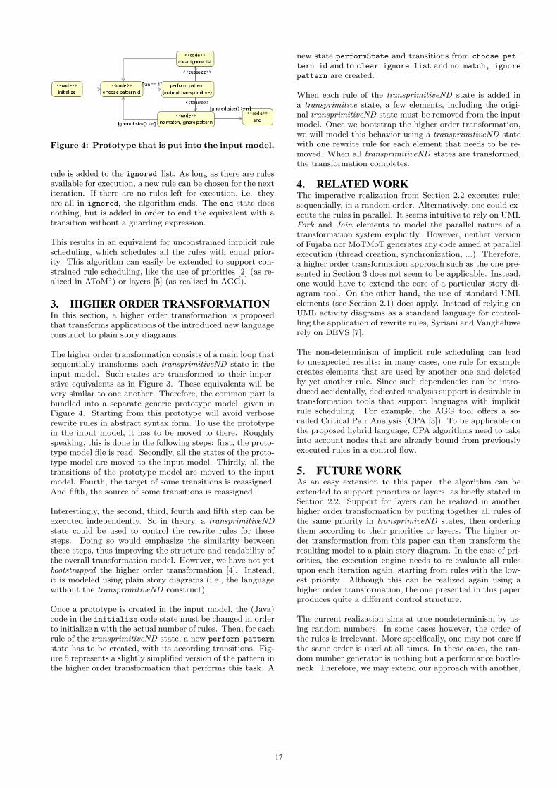
Figure 4: Prototype that is put into the input model.
rule is added to the ignored list. As long as there are rulesavailable for execution, a new rule can be chosen for the nextiteration. If there are no rules left for execution, i.e. theyare all in ignored, the algorithm ends. The end state doesnothing, but is added in order to end the equivalent with atransition without a guarding expression.
This results in an equivalent for unconstrained implicit rulescheduling, which schedules all the rules with equal prior-ity. This algorithm can easily be extended to support con-strained rule scheduling, like the use of priorities [2] (as re-alized in AToM3) or layers [5] (as realized in AGG).
3. HIGHER ORDER TRANSFORMATIONIn this section, a higher order transformation is proposedthat transforms applications of the introduced new languageconstruct to plain story diagrams.
The higher order transformation consists of a main loop thatsequentially transforms each transprimitiveND state in theinput model. Such states are transformed to their imper-ative equivalents as in Figure 3. These equivalents will bevery similar to one another. Therefore, the common part isbundled into a separate generic prototype model, given inFigure 4. Starting from this prototype will avoid verboserewrite rules in abstract syntax form. To use the prototypein the input model, it has to be moved to there. Roughlyspeaking, this is done in the following steps: first, the proto-type model file is read. Secondly, all the states of the proto-type model are moved to the input model. Thirdly, all thetransitions of the prototype model are moved to the inputmodel. Fourth, the target of some transitions is reassigned.And fifth, the source of some transitions is reassigned.
Interestingly, the second, third, fourth and fifth step can beexecuted independently. So in theory, a transprimitiveNDstate could be used to control the rewrite rules for thesesteps. Doing so would emphasize the similarity betweenthese steps, thus improving the structure and readability ofthe overall transformation model. However, we have not yetbootstrapped the higher order transformation [4]. Instead,it is modeled using plain story diagrams (i.e., the languagewithout the transprimitiveND construct).
Once a prototype is created in the input model, the (Java)code in the initialize code state must be changed in orderto initialize n with the actual number of rules. Then, for eachrule of the transprimitiveND state, a new perform pattern
state has to be created, with its according transitions. Fig-ure 5 represents a slightly simplified version of the pattern inthe higher order transformation that performs this task. A
new state performState and transitions from choose pat-
tern id and to clear ignore list and no match, ignore
pattern are created.
When each rule of the transprimitiveND state is added ina transprimitive state, a few elements, including the origi-nal transprimitiveND state must be removed from the inputmodel. Once we bootstrap the higher order transformation,we will model this behavior using a transprimitiveND statewith one rewrite rule for each element that needs to be re-moved. When all transprimitiveND states are transformed,the transformation completes.
4. RELATED WORKThe imperative realization from Section 2.2 executes rulessequentially, in a random order. Alternatively, one could ex-ecute the rules in parallel. It seems intuitive to rely on UMLFork and Join elements to model the parallel nature of atransformation system explicitly. However, neither versionof Fujaba nor MoTMoT generates any code aimed at parallelexecution (thread creation, synchronization, ...). Therefore,a higher order transformation approach such as the one pre-sented in Section 3 does not seem to be applicable. Instead,one would have to extend the core of a particular story di-agram tool. On the other hand, the use of standard UMLelements (see Section 2.1) does apply. Instead of relying onUML activity diagrams as a standard language for control-ling the application of rewrite rules, Syriani and Vangheluwerely on DEVS [7].
The non-determinism of implicit rule scheduling can leadto unexpected results: in many cases, one rule for examplecreates elements that are used by another one and deletedby yet another rule. Since such dependencies can be intro-duced accidentally, dedicated analysis support is desirable intransformation tools that support languages with implicitrule scheduling. For example, the AGG tool offers a so-called Critical Pair Analysis (CPA [3]). To be applicable onthe proposed hybrid language, CPA algorithms need to takeinto account nodes that are already bound from previouslyexecuted rules in a control flow.
5. FUTURE WORKAs an easy extension to this paper, the algorithm can beextended to support priorities or layers, as briefly stated inSection 2.2. Support for layers can be realized in anotherhigher order transformation by putting together all rules ofthe same priority in transprimiveND states, then orderingthem according to their priorities or layers. The higher or-der transformation from this paper can then transform theresulting model to a plain story diagram. In the case of pri-orities, the execution engine needs to re-evaluate all rulesupon each iteration again, starting from rules with the low-est priority. Although this can be realized again using ahigher order transformation, the one presented in this paperproduces quite a different control structure.
The current realization aims at true nondeterminism by us-ing random numbers. In some cases however, the order ofthe rules is irrelevant. More specifically, one may not care ifthe same order is used at all times. In these cases, the ran-dom number generator is nothing but a performance bottle-neck. Therefore, we may extend our approach with another,
17
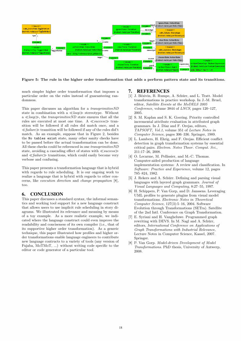
Figure 5: The rule in the higher order transformation that adds a perform pattern state and its transitions.
much simpler higher order transformation that imposes aparticular order on the rules instead of guaranteeing ran-domness.
This paper discusses an algorithm for a transprimitiveNDstate in combination with a �loop� stereotype. Withouta �loop�, the transprimitiveND state ensures that all therules are executed at most one time. A �success� tran-sition will be followed if all rules did match once, and a�failure� transition will be followed if any of the rules did’tmatch. As an example, suppose that in Figure 2, besidesthe No tables exist state, many other sanity checks haveto be passed before the actual transformation can be done.All these checks could be referenced in one transprimitiveNDstate, avoiding a cascading effect of states with �success�and �failure� transitions, which could easily become veryverbose and confusing.
This paper presents a transformation language that is hybridwith regards to rule scheduling. It is our ongoing work torealize a language that is hybrid with regards to other con-cerns, like execution direction and change propagation [8],too.
6. CONCLUSIONThis paper discusses a standard syntax, the informal seman-tics and working tool support for a new language constructthat allows users to use implicit rule scheduling in story di-agrams. We illustrated its relevance and meaning by meansof a toy example. As a more realistic example, we indi-cated where the language construct could even improve thereadability and conciseness of its own compiler (i.e., that ofits supportive higher order transformation). As a generictechnique, this paper illustrated how profiles and higher or-der transformations enable language engineers to contributenew language contructs to a variety of tools (any version ofFujaba, MoTMoT, ...) without writing code specific to theeditor or code generator of a particular tool.
7. REFERENCES[1] J. Bezivin, B. Rumpe, A. Schurr, and L. Tratt. Model
transformations in practice workshop. In J.-M. Bruel,editor, Satellite Events at the MoDELS 2005Conference, volume 3844 of LNCS, pages 120–127,2005.
[2] S. M. Kaplan and S. K. Goering. Priority controlledincremental attribute evaluation in attributed graphgrammars. In J. Dıaz and F. Orejas, editors,TAPSOFT, Vol.1, volume 351 of Lecture Notes inComputer Science, pages 306–336. Springer, 1989.
[3] L. Lambers, H. Ehrig, and F. Orejas. Efficient conflictdetection in graph transformation systems by essentialcritical pairs. Electron. Notes Theor. Comput. Sci.,211:17–26, 2008.
[4] O. Lecarme, M. Pellissier, and M.-C. Thomas.Computer-aided production of languageimplementation systems: A review and classification. InSoftware: Practice and Experience, volume 12, pages785–824, 1982.
[5] J. Rekers and A. Schurr. Defining and parsing visuallanguages with layered graph grammars. Journal ofVisual Languages and Computing, 8:27–55, 1997.
[6] H. Schippers, P. Van Gorp, and D. Janssens. LeveragingUML profiles to generate plugins from visual modeltransformations. Electronic Notes in TheoreticalComputer Science, 127(3):5–16, 2004. SoftwareEvolution through Transformations (SETra). Satelliteof the 2nd Intl. Conference on Graph Transformation.
[7] E. Syriani and H. Vangheluwe. Programmed graphrewriting with DEVS. In M. Nagl and A. Schurr,editors, International Conference on Applications ofGraph Transformations with Industrial Relevance,Lecture Notes in Computer Science, Kassel, 2007.Springer.
[8] P. Van Gorp. Model-driven Development of ModelTransformations. PhD thesis, University of Antwerp,2008.
18
Debugging Triple Graph Grammar-based ModelTransformations
Mirko SeifertTechnische Universität Dresden
Software Technology GroupDresden, Germany
Stefan KatscherTechnische Universität Dresden
Software Technology GroupDresden, Germany
ABSTRACTModel Driven Software Development heavily relies on ex-pressive and formally founded model transformations. Inthis field, Triple Graph Grammars (TGGs) have not onlybeen applied to practical problems, but shown that theirformal grounding allows sophisticated analysis of transfor-mation rules. However, creating a set of correct rules for agiven transformation problem is not easy. Practical trans-formations inherently induce complex rule sets. Hence, de-velopers of such model transformations need assistance tofind faults in their rules.This paper surveys existing debugging methods, derives aset of concepts that generally supports the localization andelimination of bugs and transfers these concepts to modeltransformations. In particular the peculiarities of TripleGraph Grammars will be addressed and essential ingredi-ents for sophisticated debug support will be presented.
Categories and Subject DescriptorsD.2.5 [Software Engineering]: Testing and Debugging
General TermsDesign
KeywordsTriple Graph Grammars, Debugging
1. INTRODUCTIONSince the early days of computer science human errors be-came manifest in software of all kinds. The search for defectsin programs has become a common activity of every softwaredeveloper’s life. Even though modern development tools sig-nificantly reduce the average number of bugs, producing zerodefect software is still not practically achievable. Addition-ally, the ever growing complexity of today’s software systemsintensifies this problem.Over the last decade, Model-Driven Software Development(MDSD) has been promoted as one promising way to tacklethis complexity, targeting reduced effort and error rates inmodern software systems. The idea is to use models to raisethe level of abstraction in software design. The motivatingassumption is that reducing the amount of information pro-vided by developers is accompanied by lower defect rates.MDSD replaces effort previously spent on coding programsin high level programming languages with other activities.Creating and transforming models, as well as generatingcode from them form the main activities within MDSD.
Obviously, these new types of activities are not error-freeby default. Due to the shift from code-centric developmentto model-driven processes, new kinds of defects arise. Er-roneous source code is replaced by invalid, inconsistent orincomplete models, faulty model transformations or evenbuggy code generators. Consequently new methods andtools are needed to detect and remove defects.If we focus on model transformations solely, we can spot avariety of existing approaches [2]. Both declarative and op-erational languages have been proposed and implemented.Among the former category, TGGs [7] provide a sophisti-cated way to specify and execute different model transfor-mation tasks. Based on a formal grounding TGGs supportbidirectional transformations, as well as model synchroniza-tion and integration.However, having a well-founded and powerful formalism doesnot guarantee the correctness of concrete model transforma-tions. Faulty transformation results can occur due to erro-neous input models, a defect set of transformation rules oreven a faulty implementation of the formalism. The contri-bution of this paper is to elaborate on existing approachesfor debugging, derive a set of debugging principles or con-cepts and transfer them to the domain of model transfor-mations. This will generate a set of requirements for modeltransformation debugging tools. Furthermore, TGGs will beexamined with respect to their specific needs when debug-ging them. Thus, the paper tackles the detection of faultsin transformation rule sets.The remainder of this paper is organized as follows: Sec-tion 2 defines basic terms, recapitulates existing methodsto debug imperative programs and derives the general con-cepts that are needed to support debugging activities. Sec-tion 3 shortly describes TGGs, in particular how they oper-ate and highlights differences to other model transformationapproaches that are important with respect to debugging.The main contribution of this paper can be found in Sect. 4,where we apply the concepts identified in Sect. 2 to modeltransformations and TGGs in particular. We conclude witha short outlook on future work in Sect. 5.
2. DEBUGGING CONCEPTSDebugging is usually defined as the process of locating andfixing bugs (i.e., errors) in programs. To be more precise,errors are implementation mistakes made by humans whichcause software to deviate from its expected behavior. Errorscan cause a program to reach a state different from the cor-rect one. If a program is in such a state, we say that there isa fault. Faults are not necessarily exposed to users because
19
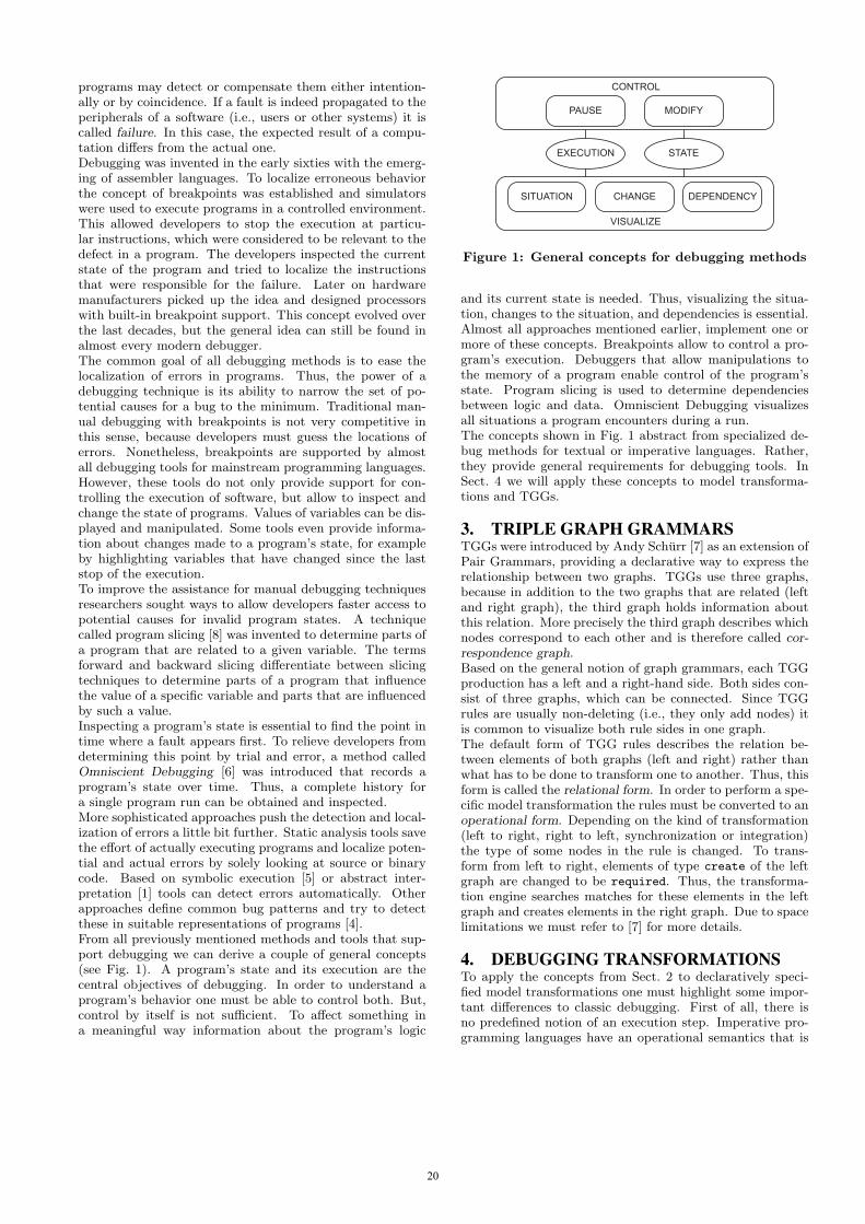
programs may detect or compensate them either intention-ally or by coincidence. If a fault is indeed propagated to theperipherals of a software (i.e., users or other systems) it iscalled failure. In this case, the expected result of a compu-tation differs from the actual one.Debugging was invented in the early sixties with the emerg-ing of assembler languages. To localize erroneous behaviorthe concept of breakpoints was established and simulatorswere used to execute programs in a controlled environment.This allowed developers to stop the execution at particu-lar instructions, which were considered to be relevant to thedefect in a program. The developers inspected the currentstate of the program and tried to localize the instructionsthat were responsible for the failure. Later on hardwaremanufacturers picked up the idea and designed processorswith built-in breakpoint support. This concept evolved overthe last decades, but the general idea can still be found inalmost every modern debugger.The common goal of all debugging methods is to ease thelocalization of errors in programs. Thus, the power of adebugging technique is its ability to narrow the set of po-tential causes for a bug to the minimum. Traditional man-ual debugging with breakpoints is not very competitive inthis sense, because developers must guess the locations oferrors. Nonetheless, breakpoints are supported by almostall debugging tools for mainstream programming languages.However, these tools do not only provide support for con-trolling the execution of software, but allow to inspect andchange the state of programs. Values of variables can be dis-played and manipulated. Some tools even provide informa-tion about changes made to a program’s state, for exampleby highlighting variables that have changed since the laststop of the execution.To improve the assistance for manual debugging techniquesresearchers sought ways to allow developers faster access topotential causes for invalid program states. A techniquecalled program slicing [8] was invented to determine parts ofa program that are related to a given variable. The termsforward and backward slicing differentiate between slicingtechniques to determine parts of a program that influencethe value of a specific variable and parts that are influencedby such a value.Inspecting a program’s state is essential to find the point intime where a fault appears first. To relieve developers fromdetermining this point by trial and error, a method calledOmniscient Debugging [6] was introduced that records aprogram’s state over time. Thus, a complete history fora single program run can be obtained and inspected.More sophisticated approaches push the detection and local-ization of errors a little bit further. Static analysis tools savethe effort of actually executing programs and localize poten-tial and actual errors by solely looking at source or binarycode. Based on symbolic execution [5] or abstract inter-pretation [1] tools can detect errors automatically. Otherapproaches define common bug patterns and try to detectthese in suitable representations of programs [4].From all previously mentioned methods and tools that sup-port debugging we can derive a couple of general concepts(see Fig. 1). A program’s state and its execution are thecentral objectives of debugging. In order to understand aprogram’s behavior one must be able to control both. But,control by itself is not sufficient. To affect something ina meaningful way information about the program’s logic
EXECUTION STATE
VISUALIZE
CONTROL
PAUSE MODIFY
CHANGESITUATION DEPENDENCY
Figure 1: General concepts for debugging methods
and its current state is needed. Thus, visualizing the situa-tion, changes to the situation, and dependencies is essential.Almost all approaches mentioned earlier, implement one ormore of these concepts. Breakpoints allow to control a pro-gram’s execution. Debuggers that allow manipulations tothe memory of a program enable control of the program’sstate. Program slicing is used to determine dependenciesbetween logic and data. Omniscient Debugging visualizesall situations a program encounters during a run.The concepts shown in Fig. 1 abstract from specialized de-bug methods for textual or imperative languages. Rather,they provide general requirements for debugging tools. InSect. 4 we will apply these concepts to model transforma-tions and TGGs.
3. TRIPLE GRAPH GRAMMARSTGGs were introduced by Andy Schurr [7] as an extension ofPair Grammars, providing a declarative way to express therelationship between two graphs. TGGs use three graphs,because in addition to the two graphs that are related (leftand right graph), the third graph holds information aboutthis relation. More precisely the third graph describes whichnodes correspond to each other and is therefore called cor-respondence graph.Based on the general notion of graph grammars, each TGGproduction has a left and a right-hand side. Both sides con-sist of three graphs, which can be connected. Since TGGrules are usually non-deleting (i.e., they only add nodes) itis common to visualize both rule sides in one graph.The default form of TGG rules describes the relation be-tween elements of both graphs (left and right) rather thanwhat has to be done to transform one to another. Thus, thisform is called the relational form. In order to perform a spe-cific model transformation the rules must be converted to anoperational form. Depending on the kind of transformation(left to right, right to left, synchronization or integration)the type of some nodes in the rule is changed. To trans-form from left to right, elements of type create of the leftgraph are changed to be required. Thus, the transforma-tion engine searches matches for these elements in the leftgraph and creates elements in the right graph. Due to spacelimitations we must refer to [7] for more details.
4. DEBUGGING TRANSFORMATIONSTo apply the concepts from Sect. 2 to declaratively speci-fied model transformations one must highlight some impor-tant differences to classic debugging. First of all, there isno predefined notion of an execution step. Imperative pro-gramming languages have an operational semantics that is
20
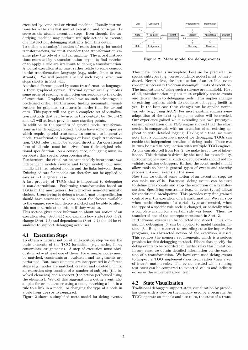
executed by some real or virtual machine. Usually instruc-tions form the smallest unit of execution and consequentlyserve as the atomic execution steps. Even though, the un-derlying machine may perform multiple actions to executeone instruction, debugging abstracts from this detail.To define a meaningful notion of execution step for modeltransformations, we must consider that transformation en-gines play the role of a virtual machine. The actual instruc-tions executed by a transformation engine to find matchesor to apply a rule are irrelevant to debug a transformation.A logical execution step must rather relate to some conceptin the transformation language (e.g., nodes, links or con-straints). We will present a set of such logical executionsteps shortly in Sect. 4.1.Another difference posed by some transformation languagesis their graphical syntax. Textual syntax usually impliessome order of reading, which often corresponds to the orderof execution. Graphical rules have no such advantageouspredefined order. Furthermore, finding meaningful visual-izations for graphical structures is harder than for textualones. This paper will not give a complete set of visualiza-tion methods that can be used in this context, but Sect. 4.2and 4.3 will at least provide some starting points.In addition to the specifics of general model transforma-tions in the debugging context, TGGs have some propertieswhich require special treatment. In contrast to imperativemodel transformation languages or basic graph transforma-tion, TGG rules cannot be applied directly. An operationalform of all rules must be derived from their original rela-tional specification. As a consequence, debugging must in-corporate this special preprocessing step.Furthermore, the visualization cannot solely incorporate twoindependent models (source and target model), but musthandle all three related models and the links between them.Existing editors for models can therefore not be applied aseasy as in the general case.A last property of TGGs that is important to debuggingis non-determinism. Performing transformation based onTGGs in the most general form involves non-deterministicchoices. Users trying to debug a transformation specificationshould have assistance to know about the choices availableto the engine, see which choice is picked and be able to affectthis non-deterministic decision if they want to.This section gives more information about our notion of anexecution step (Sect. 4.1) and explains how state (Sect. 4.2),change (Sect. 4.3) and dependencies (Sect. 4.4) should be vi-sualized to support debugging activities.
4.1 Execution StepsTo obtain a natural notion of an execution step we use thebasic elements of the TGG formalism (e.g., nodes, links,constraints, assignments). A step of execution must obvi-ously involve at least one of them. For example, nodes mustbe matched, constraints are evaluated and assignments areperformed. But, most elements are incorporated in differentsteps (e.g., nodes are matched, created and deleted). Thus,an execution step consists of a number of subjects (the in-volved elements) and a context (the action performed usingthe elements). We call this aggregation a debug event. Ex-amples for events are: creating a node, matching a link in arule to a link in a model, or changing the type of a node ina rule from create to required.Figure 2 shows a simplified meta model for debug events.
Link Constraint Preprocessing Modification
Rule Assignment Matching Creation
subjects
0..*
context
1..1
Node Subject Event DeletionContext Application
Figure 2: Meta model for debug events
This meta model is incomplete, because for practical usespecial subtypes (e.g., correspondence nodes) must be intro-duced. Nevertheless, the introduction of an artificial eventconcept is necessary to obtain meaningful units of execution.The implications of using such a scheme are manifold. Firstof all, transformation engines must explicitly create eventsand deliver them to debugging tools. This implies changesto existing engines, which do not have debugging facilitiesyet. In the best case these changes can be applied nonin-vasively (e.g., using AOP). For most existing engines someadaptation of the existing implementation will be needed.Our experience gained while extending our own prototypi-cal implementation of a TGG engine showed that the effortneeded is comparable with an extension of an existing ap-plication with detailed logging. Having said that, we mustnote that a common meta model for debugging TGGs canenable the independent creation of debug tools. These canin turn be used in conjunction with multiple TGG engines.As one can also tell from Fig. 2, we make heavy use of inher-itance. This decision is driven by the need for extensibility.Introducing new special kinds of debug events should not in-validate existing debuggers. Rather, the event model shouldallow tools to handle general types of events and therebyprocess unknown events all the same.Now that we defined some notion of an execution step, wecan make use of it. Foremost, debug events can be usedto define breakpoints and stop the execution of a transfor-mation. Specifying constraints (e.g., on event types) allowsfor conditional breakpoints. This provides very fine grainedcontrol over the execution of a transformation. We can stopwhen model elements of a certain type are created, whenthe type of a specific rule node is changed, or basically whena complete match for a certain rule was found. Thus, wetransferred one of the concepts mentioned in Sect. 2.Furthermore, events can be collected and stored. Thus, om-niscient debugging [6] can be applied to model transforma-tions [3]. But, in contrast to recording state for imperativeprograms, an abstracted notion of the execution is used.This reduces the memory requirements, which is a seriousproblem for this debugging method. Filters that specify thedebug events to be recorded can further relax this limitation.In any case, we obtain detailed information on the execu-tion of a transformation. We have even used debug eventsto inspect a TGG implementation itself rather than a setof transformation rules. The events created while runningtest cases can be compared to expected values and indicateerrors in the implementation itself.
4.2 State VisualizationTraditional debuggers support state visualization by provid-ing users with a view on the memory used by a program. AsTGGs operate on models and use rules, the state of a trans-
21

EVENTS MODELSRULES
VISUALIZE
ELEMENT CREATIONATTRIBUTE MODIFICATION
MATCHING STATUSCONSTRAINT EVALUATION
TRACESEVENTS HISTORY
MATCHING HISTORY
CONTROL
BREAKPOINTS EDITORS
Figure 3: Elements for debugging TGGs
formation is the state of all involved models plus the rules.The involved models can be visualized using their existinggraphical editors. However, visualization must incorporatethe correspondence model. Coupling two existing editors(for the left and right model) with a third one (for the cor-respondence model) is probably a good option to do so.Likewise, transformation rules must be available to users.But, rules must not be shown only, but adapted accordingto their current matching state. Assigning special color tomatched elements is probably an intuitive way to providethis information to users. Changing the color of matchedelements can also be applied to model elements.
4.3 Change VisualizationVisualizing changes that occur during a transformation isimportant to find defects in rule sets. Based on the eventsdefined in Sect. 4.1, we can mark all model elements thatwere modified or added. Furthermore, accumulating a listof all modification events provides a history of all changesand the order they were applied in. This modification tracegives detailed information about the concrete effects of arule set.
4.4 Dependency VisualizationSimilar to the previously mentioned program slicing [8] de-pendencies can provide important clues about the locationof defects. Knowing the set of possible causes for a certaineffect can drastically reduce the effort needed for debugging.Speaking about model transformations, different kinds of de-pendencies are present. Newly created model elements de-pend on a set of elements in the source model. They alsodepend on the presence of a specific rule that matched theseelements. If constraints are used they must be added to theset of dependencies as well.To obtain all these dependency information we recommendto create traces for all new elements. These traces shouldcontain details about the matched rule, the matched ele-ments and checked constraints. Luckily, all this informationis already present in the list of events created during a trans-formation run. Traces are basically an abstraction over thesequence of events that provide distilled information aboutdependencies. Using colors and existing editors for modelsand rules, can again support this visualization graphically.
Finally, a summary of all ideas mentioned above, can befound in Fig. 3. We replaced the concepts identified inSect. 2 with their concrete counterparts for the context ofmodel transformations.
5. CONCLUSION AND FUTURE WORKAfter analyzing existing debugging methods and tools, wehave derived a set of general concepts that are needed tosupport debugging activities. Controlling and visualizingthe execution and the state of a process is important to finddefects. We applied these concepts to model transformationsby introducing debug events as a natural notion of executionstep. We provided a simple meta model for debug events andexplained how they support both control and visualizationof a transformation’s execution. Furthermore we collecteda set of requirements on visualizing the state of a transfor-mation (i.e., the involved models and rules). Some of thepresented concepts can be applied to model transformationsin general, others are specific to TGGs. Furthermore, we areconvinced that agreement on a common debug event modelcan enable transformation independent debugger implemen-tation.In the near future we plan to finish the implementation ofthe mentioned concepts. This will allow us to gain practi-cal experience and to validate the presented ideas. As thegraphical syntax of TGG rules has some disadvantages (e.g.,no predefined reading order), we want to create a textualcounterpart. This implies other disadvantages (e.g., a syn-tactical gap between the models and rules that transformthem). Thus, we will compare both syntaxes with respectto their usability for debugging activities.
6. ACKNOWLEDGMENTSThis work has been partially funded by the German Ministryfor Education and Research in the SuReal project.
7. REFERENCES[1] P. Cousot and R. Cousot. Abstract interpretation: a
unified lattice model for static analysis of programs byconstruction or approximation of fixpoints. InConference Record of the Fourth Annual ACMSIGPLAN-SIGACT Symposium on Principles ofProgramming Languages, pages 238–252, Los Angeles,California, 1977. ACM Press, New York, NY.
[2] K. Czarnecki and S. Helsen. Classification of modeltransformation approaches. In OOPSLA 2003Workshop on Generative Techniques in the context ofModel Driven Architecture, oct 2003.
[3] M. Hibberd, M. Lawley, and K. Raymond. ForensicDebugging of Model Transformations. In G. Engels,B. Opdyke, D. C. Schmidt, and F. Weil, editors,MoDELS, volume 4735 of LNCS, pages 589–604.Springer, 2007.
[4] D. Hovemeyer and W. Pugh. Finding bugs is easy.SIGPLAN Notices, 39(12):92–106, 2004.
[5] J. C. King. Symbolic Execution and Program Testing.Communication of the ACM, 19(7):385–394, 1976.
[6] B. Lewis. Debugging Backwards in Time. TheComputing Research Repository, cs.SE/0310016, 2003.
[7] A. Schurr. Specification of Graph Translators withTriple Graph Grammars. In E. W. Mayr, G. Schmidt,and G. Tinhofer, editors, Proceedings of 20thInternational Workshop on Graph-Theoretic Conceptsin Computer Science, Herrsching, Germany, volume 903of LNCS. Springer Verlag, 1994.
[8] M. Weiser. Program Slicing. IEEE Transactions onSoftware Engineering, 10(4):352–357, 1984.
22
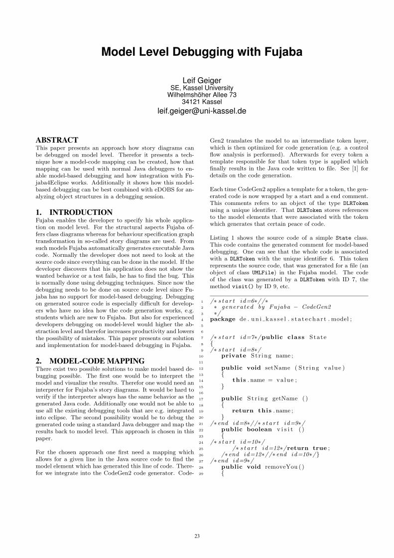
Model Level Debugging with Fujaba
Leif GeigerSE, Kassel University
Wilhelmshöher Allee 7334121 Kassel
ABSTRACTThis paper presents an approach how story diagrams canbe debugged on model level. Therefor it presents a tech-nique how a model-code mapping can be created, how thatmapping can be used with normal Java debuggers to en-able model-based debugging and how integration with Fu-jaba4Eclipse works. Additionally it shows how this model-based debugging can be best combined with eDOBS for an-alyzing object structures in a debugging session.
1. INTRODUCTIONFujaba enables the developer to specify his whole applica-tion on model level. For the structural aspects Fujaba of-fers class diagrams whereas for behaviour specification graphtransformation in so-called story diagrams are used. Fromsuch models Fujaba automatically generates executable Javacode. Normally the developer does not need to look at thesource code since everything can be done in the model. If thedeveloper discovers that his application does not show thewanted behavior or a test fails, he has to find the bug. Thisis normally done using debugging techniques. Since now thedebugging needs to be done on source code level since Fu-jaba has no support for model-based debugging. Debuggingon generated source code is especially difficult for develop-ers who have no idea how the code generation works, e.g.students which are new to Fujaba. But also for experienceddevelopers debugging on model-level would higher the ab-straction level and therefor increases productivity and lowersthe possibility of mistakes. This paper presents our solutionand implementation for model-based debugging in Fujaba.
2. MODEL-CODE MAPPINGThere exist two possible solutions to make model based de-bugging possible. The first one would be to interpret themodel and visualize the results. Therefor one would need aninterpreter for Fujaba’s story diagrams. It would be hard toverify if the interpreter always has the same behavior as thegenerated Java code. Additionally one would not be able touse all the existing debugging tools that are e.g. integratedinto eclipse. The second possibility would be to debug thegenerated code using a standard Java debugger and map theresults back to model level. This approach is chosen in thispaper.
For the chosen approach one first need a mapping whichallows for a given line in the Java source code to find themodel element which has generated this line of code. There-for we integrate into the CodeGen2 code generator. Code-
Gen2 translates the model to an intermediate token layer,which is then optimized for code generation (e.g. a controlflow analysis is performed). Afterwards for every token atemplate responsible for that token type is applied whichfinally results in the Java code written to file. See [1] fordetails on the code generation.
Each time CodeGen2 applies a template for a token, the gen-erated code is now wrapped by a start and a end comment.This comments refers to an object of the type DLRToken
using a unique identifier. That DLRToken stores referencesto the model elements that were associated with the tokenwhich generates that certain peace of code.
Listing 1 shows the source code of a simple State class.This code contains the generated comment for model-baseddebugging. One can see that the whole code is associatedwith a DLRToken with the unique identifier 6. This tokenrepresents the source code, that was generated for a file (anobject of class UMLFile) in the Fujaba model. The codeof the class was generated by a DLRToken with ID 7, themethod visit() by ID 9, etc.
1 /∗ s t a r t id=6∗//∗2 ∗ genera ted by Fujaba − CodeGen23 ∗/4 package de . u n i k a s s e l . s t a t e c h a r t . model ;5
6
7 /∗ s t a r t id=7∗/public class State8 {9 /∗ s t a r t id=8∗/
10 private St r ing name ;11
12 public void setName ( St r ing value )13 {14 this . name = value ;15 }16
17 public St r ing getName ( )18 {19 return this . name ;20 }21 /∗end id=8∗//∗ s t a r t id=9∗/22 public boolean v i s i t ( )23 {24 /∗ s t a r t id=10∗/25 /∗ s t a r t id=12∗/return true ;26 /∗end id=12∗//∗end id=10∗/}27 /∗end id=9∗/28 public void removeYou ( )29 {
23

30 }31 }32 /∗end id=7∗/33 /∗end id=6∗/
Listing 1: Source code example with comments
Such source code may now be changed by some externaltools like e.g. the eclipse code formatter or the EMF codegenerator with might generate additional constructs into theclass. Afterwards the source code is reread and a tree ofDLRToken is created according to the comments found inthe file. Afterwards the file is written back without thecomments. Figure 1 shows such a tree for the file of Listing1.
The d0 object of the singleton class DLRTool has a list withall open projects for which code was generated. Here this isjust the project represented by the object d1. From there thetree is created by the children links. Every token in the treeknows the line of code where the code generated for that to-ken starts and the line where it ends. Additionally it storesthe character offset and the character length of the codeblock. Every token also has a comment attribute which storesa String describing what this code block does. The comment
is not shown in Figure 1 to keep it readable. The token withID 7 e.g. covers the lines from line 7 to line 32 in Listing1. For that token the object of type ElementReference isalso shown. This object connects the token with the corre-sponding model element. Here this is the UMLClass objectu16. Using this tree every line in a Java file can be tracedback to the model elements that originally created that line.
3. JSR-045 AND SMAPThe previous section described a code-model mapping. Tonow enable model-based debugging this mapping needs tobe integrated into the debugging process. That means itshould be possible to place breakpoints on model elementsor to stepwise execute a story diagram. The Java VM offersan interface for such purposes. That interface is defined inJSR-045 Debugging Support for Other Languages 1.
JSR-045 is originally made to allow debugging a textual lan-guage other than Java using the standard Java debugger. Todebug an application in a different language using JSR-045,for every source code file a so-called SMAP file must be pro-vided. The SMAP file specifies which line in which file inthe source language corresponds to which line and file in thetarget language which is normally Java.
To now debug Fujaba diagrams using JSR-045 one need toconvert the mapping tree described in the previous chapterto a SMAP file. Note, that we are mapping a graphical lan-guage to a textual one here. But that is no big problem sinceour approach simply takes the IDs of the DLRToken in thetree as source language line number. Additionally, the treehas to be converted to a list. This is done by traversing thetree depth-first and relate every line of the target languageto the token which generates this line and is deepest in thetoken tree.
1http://jcp.org/aboutJava/communityprocess/final/jsr045/index.html
The tree from Figure 1 would generate the SMAP file shownin Listing 2. The SMAP file starts with a header that statesthe target file (State.java, line 2) and the name of the sourcelanguage (Fujaba, line 3). Line 6 holds the name of the tar-get file and the mapping starts at line 8. A single mappingalways looks like this: It starts with the start line in thesource file (here the ID of the DLRToken). Then comes a“#” sign followed by the number of the source file (here al-ways 1, see line 6). Then the number of repetitions mightbe given starting with a comma. This makes only sense fortext-to-text mapping so it is not needed here. After a colonthe target line number and separated by a comma the lengthof the code block is stated.
1 SMAP2 State . java3 Fujaba4 ∗S Fujaba5 ∗F6 1 . . \ . . \ . . \ . . \ StatechartDLR . c t r7 ∗L8 6#1:1 ,69 7#1:7 ,2
10 8#1:9 ,1211 9#1:21 ,312 10#1:2413 12#1:2514 9#1:2615 7#1:27 ,516 6#1:3217 ∗E
Listing 2: SMAP file for the source code from List-ing 1
The lines 9 and 15 in Listing 2 e.g. specify that the lines 7-8and 27-32 in the Java file from Listing 1 are generated by theDLRToken with ID 7. That means that lines are generatedby the UMLClass element in the Fujaba model.
The information from the SMAP file is now compiled intothe Java class file using a post-compiler and can then beused by every debugger that supports the JSR-045, like thedebugger integrated in eclipse.
4. FUJABA4ECLIPSE INTEGRATIONWe have written a Fujaba4Eclipse plugin so that the ap-proach described above can be used to debug Fujaba dia-grams in Fujaba4Eclipse. Figure 2 shows that model-baseddebugger in action. Due to the SMAP integration it is nowpossible to add breakpoints to model elements, as shown inthe Breakpoint View in Figure 2. The debugger just hitsuch a breakpoint. That is why the story diagram is openedin the Fujaba Editor and the corresponding model elementis highlighted. The comment of the DLRToken, describingwhat would happen next, is shown in the status bar. In thiscase the debugger has stopped just before the target linkis created. The Debug View in Figure 2 shows the stacktrace of the suspended thread. Here it is possible to jumpto elements higher in the stack trace or to change the debug-ger from model-based debugging to code-based debugging.In the Variables View the developer can analyze the localvariables and the current object structure when the VM issuspended. It is somehow difficult to compare a pattern ina story diagram to the current object structure using the
24

Variables View to e.g. find out why a pattern fails. To solvethis problem the eDOBS plugin described in the next chap-ter lifts the visualization of the object structure to modellevel.
5. EDOBSeDOBS is an Eclipse plugin, which visualizes the currentheap of a Java program at runtime as a UML object dia-gram [2]. eDOBS may typically be used within a debuggingsession. Instead of the variable view, the eDOBS panel mayshow the content of variables and how the referenced objectsare related to each other. Figure 3 shows eDOBS visualiz-ing the object structure while debugging the example fromFigure 2.
To make the comparison of the current object structure ineDOBS and a story pattern in Fujaba easier, we have an-notated all local variables names to the objects the variablecurrently stores. This is done by visualizing the names asnotes behind the object name in eDOBS. In Figure 3 onecould see, that the object s0 is currently the this object,the object s1 is stored as local variable sc, etc. Of courseone object in eDOBS can have multiple variable names. Ad-ditionally, all objects currently not stored in any local vari-able, that means all object not visible in the current methodblock, are shown semi-transparent. This way it is quite easyto identify a pattern in the current object structure and e.g.analyze why the matching is not successful.
When exploring object structures in eDOBS, the way backto the Eclipse or Fujaba4Eclipse artifact is offered for allelements. That means that you can jump from an object /attribute / method in eDOBS directly to the source code orto the corresponding Fujaba4Eclipse diagram.
6. CONCLUSIONSThe paper has presented an approach to enable model-baseddebugging in Fujaba. The result is implemented as eclipseplugin in the CodeGen2 repository. It was tested with somesmall examples, e.g. the Fujaba Solution for the AntWorldSimulation Tool Case at the 4th International Workshop onGraph-Based Tools2. In our opinion model-based debugginghelped alot when searching for bugs in those examples.
7. REFERENCES[1] L. Geiger, C. Schneider, and C. Reckord. Template-
and modelbased code generation for MDA-Tools. InH. Giese and A. Zundorf, editors, Proc. of the thirdInternational Fujaba Days 2005, Paderborn, Germany,volume tr-ri-05-259 of Technical Report, pages 57–62,Paderborn, Germany, September 2005. University ofPaderborn.
[2] L. Geiger and A. Zundorf. eDOBS - GraphicalDebugging for eclipse. Electronic Communications ofthe EASST, 1, 2006.
2http://www.fots.ua.ac.be/events/grabats2008/
25

Figure 1: Mapping tree
Figure 2: Model-based debugging in action
26

Figure 3: Model-based debugging with eDOBS
27

Fujaba’s Future in the MDA Jungle
Fully Integrating Fujaba and the Eclipse Modeling Framework?
Basil Becker, Holger Giese, Stephan Hildebrandt, Andreas SeibelHasso Plattner Insitute for Software System Engineering
Prof.-Dr.-Helmertstr. 2-314482 Potsdam, Germany
{Basil.Becker|Holger.Giese|Stephan.Hildebrandt|Andreas.Seibel}@hpi.uni-potsdam.de
ABSTRACTFujaba has a long tradition as a CASE tool and providesoutstanding features with its proprietary extensions in formof Story Diagrams and TGGs. However, in its current formFujaba is not ready to support the development of tools orapplications for MDA. In this paper, we report about ourlatest work on Fujaba and Eclipse and outline the used so-lutions developed and employed so far. In addition, we out-line our vision of the next open Fujaba version, which moresmoothly integrates with standard MDA environments andthus could help that the Fujaba concepts and our researchresults can be employed in standard development projectsin the MDA world.
1. INTRODUCTIONFujaba has a long tradition as a CASE tool and providesoutstanding features with its proprietary extension in formof code generation for UML Class Diagrams [5], Story Dia-grams [2] and TGGs [4]. However as outlined in this paper,Fujaba is currently not ready to support the developmentof MDA tools or applications. To employ Fujaba and itsconcepts, we have to restrict our projects to UML modelsencoded with the proprietary UML dialect supported by Fu-jaba. In practical applications, also other MDA techniquesare required, which have to be used in combination. In fact,an open version of Fujaba is required, which can be employedin a well established technological platform.
To be compatible with such a platform, Fujaba must beable to support not only its proprietary UML models asbasis for its concepts but also standard meta models andthe standard APIs possibly generated by other non Fujabacode generators. The Fujaba offspring MOFLON [1] withits support for MOF 2.0 thus seems to be a good solution.However, neither MOF 1.x nor MOF 2.0 has found muchacceptance in practice due to its complexity. Instead, theEclipse Modeling Framework (EMF)1 has become more orless the quasi-standard for meta modeling, which provides apartial implementation of the OMGs Essential Meta ObjectFacility (EMOF) in form of the Ecore meta meta model.In addition to basic support for modeling meta models andcode generation from the Ecore meta models, EMF also pro-vides model serialization/de-serialization and validation fa-cilities. Furthermore, a large variety of other tools for thedevelopment of tools for MDA and DSLs based on EMF ex-
1http://www.eclipse.org/modeling/emf/
ist, e.g., openArchitectureWare2, ATL3 and GMF4. Also anumber of modeling tools already employ EMF such as theUML2 Tools 5 for UML 2.0 modeling and TOPCASED6 forSysML modeling.
In this paper, we report about our latest work on Fu-jaba and Eclipse and outline the used solutions developedand employed so far. In addition, we outline our visionof the next open Fujaba version, which more smoothly in-tegrates with standard MDA environments and thus couldhelp that the Fujaba concepts and our research results canbe employed in standard development projects in the MDAworld.
The paper is structured as follows: we first present ourcurrent achievements and requirements for the meta modelbased development of tools in Section 2 looking into metamodeling (Section 2.1), Story Diagrams (Section 2.2), TripleGraph Grammars (Section 2.3) and consistency rules (Sec-tion 2.4). Then, we discuss our requirements for UML 2.0based development of applications in Section 3. Finally, wediscuss our findings in Section 4 looking into open issues andour envisioned solution before our final conclusions.
2. META MODEL BASED TOOL DEVEL-OPMENT
2.1 Meta ModelingFujaba uses a proprietary meta meta model to representmeta models. This makes interoperation with modelingtools, based on other meta meta models, difficult. To createtransformation rules for our model transformation system(described in Section 2.3), we first have to import the exist-ing EMF meta models of the models, we want to transform,into Fujaba. Unfortunately, there was no possibility to im-port EMF based meta models into Fujaba, so far. Manuallyremodeling meta models is usually not an option due to thecomplexity of these meta models (e.g., UML 2.0). There-fore, we developed a simple import plugin for Fujaba, whichuses EMF to de-serialize Ecore files and create the EMFmodel tree in-memory. This tree is then traversed in orderto create a new Class Diagram, classes, attributes, methods,generalizations and associations into Fujaba.
2http://www.openarchitectureware.org/3http://www.eclipse.org/m2m/atl/4http://www.eclipse.org/modeling/gmf/5http://www.eclipse.org/uml26http://www.topcased.org
28

Problems arise if the Ecore model is split among severalfiles. An example is the SysML meta model used in TOP-CASED7. This meta model references the UML 2.0 metamodel from the UML 2.0 plugin, which in turn referencesthe Ecore meta model. Within Eclipse, platform URIs areoften used to reference elements in models provided by otherplugins. In Fujaba, these URIs cannot be resolved, of course.Therefore, the meta models have to be extracted from theproviding plugins, put into the same directory, and all ref-erences in the files have to be made relative using a texteditor.
Then, all models can be imported into Eclipse in the orderin which they depend on each other. In the SysML case, firstthe Ecore meta model must be imported because it is inde-pendent from the other models. Then, the UML 2.0 metamodel and finally the SysML meta model can be imported.The reason is, that elements referenced from another file arenot converted to Fujaba by the importer. The Fujaba ob-jects must already exist. After the import, the meta modelsare available for use in Fujaba.
2.2 Story DiagramsStory Diagrams allow modeling behavior, using graph rewrit-ing rules. They are similar to Activity Diagrams extendedby special Story Activities that contain graph rewriting rules.In Fujaba, Story Diagrams specify the behavior of a methodrelated to a class. A code generator can generate Java codefrom these Story Diagrams that implements the modeledbehavior.
Nevertheless, a problem occurs with meta models im-ported from EMF. In Fujaba, compositions are always bi-directional. This is not required in EMF. EMF provides themethod eContainer() to access the container of a containedelement. Importing a unidirectional EMF composition intoFujaba, automatically creates an explicit inverse associationfrom the contained element to the container. Of course, thisassociation does not exist in the EMF model or the codegenerated by EMF. This poses a problem for Fujaba’s codegeneration from Story Diagrams because the code generatormight use these non-existent associations in the generatedcode. This makes the generated code incorrect and it mustbe corrected manually.
2.3 Triple Graph GrammarsIn the context of Model-Driven Development (MDD), vari-ous different models describe a system under construction.These models can be used to describe different aspects, sub-systems or overlapping parts of the system at different lev-els of abstraction. Thus, models are not completely inde-pendent but rather relationships between them exist, e.g.,models are derived from other models by means of modeltransformations or they are kept in sync by means of modelsynchronization. Model transformation and synchroniza-tion require a transformation system to transform differ-ent model types and propagate changes between models. Amodel transformation system must be seamlessly capable ofbeing integrated into an existing tool chain.
The Triple Graph Grammar (TGG) based model trans-formation system introduced in [3, 4] has recently been mi-grated to Eclipse. Thus, TGG based model transformations
7We encountered this problem in an industrial developmentproject where a model transformation for SysML models wasdeveloped.
Source
Modeling
Tool
Target
Modeling
Tool
Transforma-
tion System
Source
Model
Target
Model
Transforma-
tion Rules
Source
Modeling
Tool
Adapter
Target
Modeling
Tool
Adapter
Figure 1: Overview of an in-memory transformation
can be easily used within Eclipse. This integration also al-lows exploiting EMFs change notification mechanism for ef-ficient synchronization of models. However, the transforma-tion rules, that perform the actual transformation, are notcreated within Eclipse but within Fujaba by means of StoryDiagrams.
2.3.1 Model Transformation on EMF Models usingTriple Graph Grammars
The model transformation system consists of a series ofEclipse plugins. Core of the transformation system is thetransformation engine. It loads the source model of thetransformation and the required set of transformation rulesto create a target model. The engine is independent fromthe model types. It just executes the transformation rules,which perform the actual model transformation. The trans-formation rules are therefore specific for two types of models,the source and the target model. Transformation rule setsare deployed as separate Eclipse plugins.
The TGG-based model transformation algorithm supportsbidirectional model transformation and synchronization. Thetransformation can be executed on two conceptual levels:file-based transformations and in-memory transformations.The file-based transformation loads the source model filefrom disk and saves the transformed target model to disk,as well.The in-memory model transformation (shown in Figure 1)directly manipulates the models in the modeling tools’ mem-ory. For this purpose, a special tool adapter is required thatallows accessing the models. If the modeling tool is anotherEMF-based Eclipse plugin, such an adapter is usually quitesimple. In that case, the adapter just has to open the mod-eling tool, get the resource object that contains the model,and return it to the transformation engine. The transfor-mation engine can then operate directly on the model. Ifthe modeling tool is an external program, the adapter ismuch more complex and must translate modifications fromthe EMF modeling space to the external modeling tool, e.g.,via COM or .NET whenever the external tool provides anappropriate interface. To execute a model transformation,the user has to provide a source and target model and a setof transformation rules.
2.3.2 Creating Model Transformation Rules with Fu-jaba
Figure 2 shows the main steps, which are required to cre-ate transformation rules within Fujaba. Before the actualtransformation rules can be defined, the meta models of thesource and target models must be available in Fujaba. Incase of Ecore meta models, these must be either remod-eled or imported into Fujaba. Besides the source and tar-get meta models, a third correspondence model is requiredfor a model transformation with TGGs. This correspon-
29

Import EMF
Meta Models
Create TGG
Rules
Derive Story
Diagrams
Generate
Transformation
Rule Java
Code
Adapt Java
Code Manually
Put Java Code
into Eclipse
Plugin
Deploy
Transformation
Rule Plugin
Use
Transformation
Rules
Create
Configuration
Files
Figure 2: Necessary steps to create executabletransformation rules from TGG rules
dence model captures traceability links between correspond-ing source and target model elements. Of course, a corre-spondence meta model is required that describes the avail-able types of correspondence nodes and their inheritancerelationships. In addition to the meta models of the modelsto be transformed, the meta model of the transformationsystem itself is required. This meta model is also availableas an Ecore model and must be imported into Fujaba, aswell.
When all necessary meta models are available in Fujaba,the TGG rules can be specified with the Fujaba TGG edi-tor. While these TGG rules are only declarative, operationaltransformation rules have to be derived afterwards in formof Story Diagrams. For each TGG rule and each transforma-tion direction a separate Story Diagram is derived. The gen-erated Story Diagrams are the basis for the subsequent codegeneration. The code generator has to generate proper EMFcompatible access methods for object creation and modifica-tion. For example, factories create all EMF objects. Thesefactories must be used in the generated code to create newEMF objects.
The current code generation (CodeGen2 plugin) of Fu-jaba already supports the generation of EMF compatiblecode. To enable the EMF code generation, the code styleattribute of all model elements must be set to ”emf“. Thegenerated Java code is then integrated into an Eclipse pluginproject. Due to the issue described in Section 2.2, severalmanual corrections of the code may be necessary. In thementioned industry project, this issue posed a huge obsta-cle because the UML 2.0 meta model contains mostly uni-directional compositions and the code generator extensivelyuses the false inverse associations. These errors had to becorrected manually in the generated code.
Besides the classes for the actual transformation rules,some more helper classes and configuration files need to becreated manually that, e.g. describe the type of modelsthe transformation rules can be used for. Especially, thetransformation rule plugin has to implement an extensionpoint provided by the transformation system. The trans-formation system employs this extension point to discoveravailable transformation rules. Currently, these configura-tion files have to be created by the user but rather shouldbe created automatically.
2.4 Consistency RulesWe are currently working on another MDA application, whichis a tool for model-based development of UML based appli-cations deployment where we employ the notion of compo-
Meta-Model 1
Domain SpecificModel 1
ConsistencyRules
MDA Tool
Fujaba
specified on
applied on
conform to
Meta-Model n
Domain SpecificModel n
...
consistent to
applied on
specified on
conform to
Figure 3: Conceptual integration of Fujaba and anEclipse-based MDA tool for consistency rule speci-fication
nent development and component configuration & deploy-ment. The developed software components provide soft-ware development aspects as well as deployment aspects likewell defined variation points for configuration during deploy-ment.
Fujaba does not provide the necessary modeling artifactsfor this problem domain. In contrast, Eclipse does providewith EMF an appropriate environment for defining metamodels, based on Ecore. Thus, we employ Eclipse and EMFas modeling environment. However, Fujaba is still a majorpart of the tool because we define consistency rules betweendomain specific models by means of Story Diagrams. Figure3 shows the tool, its artifacts, the role of Fujaba and therelationships between these artifacts.Consistency rules have to be specified on the meta modelsand are subsequently applied on the domain specific models,which are conform to their meta-models (instantiations). Ifrelationships between domain specific models exist, which isquite common in our case, consistency rules are applied inorder to check whether all required domain specific modelsare consistently modeled.
In order to realize such a tool, we employ the previouslyexplained EMF importer and the EMF code generation ca-pability of Fujaba’s code generation. Thus, we import theEMF meta models into Fujaba, specify the consistency rulesbased on these meta models and subsequently generate EMFcompatible code for the consistency rule application withinEclipse.
2.5 Open IssuesThe major issue is the different meta meta models of Fu-jaba and EMF. This requires a conversion of meta modelsof one type to another. However, this conversion does notwork seamlessly because of the major conceptual differences.One mentioned problem is compositions, which are alwaysbidirectional in Fujaba. This makes the generation of correctJava code in Fujaba difficult.
Furthermore, the described workflow for creating a setof transformation rules is far too complex for an ordinaryuser of the transformation system. The process involves twodifferent platforms, Eclipse and Fujaba, and requires a lotof manual steps. This workflow must be limited to only oneplatform and be automated as much as possible.
30

3. UML 2.0 BASED APPLICATION DEVEL-OPMENT
Fujaba does not allow UML 2.0 based application develop-ment, yet. It is missing the capability of modeling compo-nent based systems, a feature, which is nowadays of majorimportance. Of course, it is possible to add componentsand all other missing modeling aspects to Fujaba’s metameta model, but this is related to huge implementation ef-forts. Obviously, this reduces or even circumvents Fujaba’susage in industry cooperation’s, as industry mostly uses andarrogates UML 2.0 conform models, respectively.
Story Diagrams can only be used with Fujaba models andwithin these models only for objects. But using them forother modeling artifacts providing a similar instantiationconcept, i.e. components, would be a great benefit. How-ever, it is impossible to use the modeling capabilities of dif-ferent MDA / CASE tools and then use Fujaba to extendthese capability by means of Story Diagrams. Following, if adeveloper wants to use Story Diagrams, she/he is currentlylocked in Fujaba.
4. DISCUSSIONThe sketched workflow of Section 2.3.1 is not quite opti-mal. Two different platforms and meta meta models, Fu-jaba and EMF, have to be used. Fujaba does only supportClass Diagrams of UML 2.0, which are even not completelycompatible to UML 2.0. The import of EMF models intoFujaba and the code generation of Fujaba do not work per-fectly, yet. Necessary configuration files cannot be createdautomatically at all and several manual steps are required.Furthermore, TGGs and Story Diagrams are not availableas EMF models, which would allow model transformationson these models using the explained transformation system.The main cause for these issues is the gap between the metameta models that must be bridged somehow.
To overcome these problems, the tool chain should be lim-ited to a single platform. Because EMF is already widelyin use, it is the canonical choice. However, this requires themigration or redevelopment of editors for TGGs and StoryDiagrams as well as a code generation from Story Diagrams.Although Fujaba4Eclipse already tried to integrate Fujabawithin Eclipse, the migration did only change the user in-terface but the underlying technology is still incompatibleto EMF.
Therefore, reusing established technologies of the Eclipseworld must leverage the integration of Fujaba and Eclipse.Reusing EMFs widely used meta meta model would makeFujaba compatible to other EMF based tools and would alsoreduce maintenance effort. Such tools could also be reusedand do not need to be redeveloped for Fujaba anymore.
This also opens another possibility for the generation ofStory Diagrams from TGG rules as explained in Section2.3.2. Up to now, the generation of Story Diagrams fromTGG rules is hard coded. This complicates the subsequentdevelopment of the transformation algorithm because a largepart of the algorithm is contained in the operational trans-formation rules. If the transformation algorithm is modified,the generation algorithm for the Story Diagrams has to bechanged, as well. If TGG and Story Diagrams were alsoEMF models, the transformation algorithm itself could beused to create the Story Diagrams. Only a set of transfor-mation rules has to be provided that transform TGGs into
Story Diagrams. To modify the transformation algorithm,only this set of transformation rules has to be adapted.
To achieve the described goal, we are currently working onthe development of a Story Diagram editor based on GMF.Because Story Diagrams are quite similar to UML ActivityDiagrams, we simply extend the UML 2.0 meta model pro-vided by the UML 2.0 plugin by reusing intersecting parts.Subsequently, a code generator for Story Diagrams must bedeveloped because a Story Diagram’s semantic is expressedin terms of the resulting code. EMFs code generation mech-anism can be reused to generate the main structure of thecode but a tailored code generation is required to generatecode from the behavior modeled by means of Story Dia-grams.
A drawback of the sketched solution is that story-drivenmodeling is then limited to Ecore models. Although, StoryDiagrams and their associated Class Diagrams are based onUML 2.0, these Class Diagrams have to be converted toEcore models in order to use EMFs code generation. Thisis a restriction because Ecore provides only a subset of theconstructs supported by MOF or Fujaba. A code genera-tor that can generate Java code directly from the UML 2.0model without a prior conversion to Ecore can solve thisproblem.
5. CONCLUSIONIn this paper, we have presented two major issues that ap-peared in our recent work. First, the future of meta-modelingseems to be hold by EMF and second, Fujaba’s Story Dia-gram and TGG features are important for engineering qual-ity software. We have experienced and explained that Fu-jaba provides only poor compatibility to EMF and thereforeis going to loose track of further developments in MDD. Toovercome this, we propose to open Fujaba towards EMFand benefit from EMFs success on the one hand and en-abling Fujaba’s key technologies on the other hand, such asStory Diagrams and TGGs for EMF based development.
6. REFERENCES[1] C. Amelunxen, A. Konigs, T. Rotschke, and A. Schurr.
MOFLON: A Standard-Compliant MetamodelingFramework with Graph Transformations. In ModelDriven Architecture - Foundations and Applications:Second European Conference, volume 4066 of LNCS,pages 361–375. Springer Verlag, 2006.
[2] L. Geiger, C. Schneider, and C. Reckord. Template-and modelbased code generation for MDA-Tools. In 3rdInternational Fujaba Days, Paderborn, Germany,September 2005.
[3] H. Giese and S. Hildebrandt. Incremental modelsynchronization for multiple updates. In Proceedings ofGraMoT’08, May 12, 2008, Leipzig, Germany, volumeProceedings of GraMoT’08, May 12, 2008, Leipzig,Germany, 2008.
[4] H. Giese and R. Wagner. From model transformationto incremental bidirectional model synchronization. InSoftware and Systems Modeling, 28 March 2008.
[5] U. Nickel, J. Niere, and A. Zundorf. The FUJABAenvironment. In ICSE ’00: Proceedings of the 22ndinternational conference on Software engineering, pages742–745, New York, NY, USA, 2000. ACM Press.
31

Letting EMF Tools Talk to Fujaba through Adapters
Jendrik JohannesTechnische Universität Dresden
Software Technology Group01062 Dresden, Germany
ABSTRACTMany software modelling tools are built on top of the EclipseModeling Framework (EMF) through which they can com-municate and exchange models. In contrast to that, the Fu-jaba Toolsuite defines its own modelling framework. Bothframeworks are built on the same concepts of software mod-elling. Therefore, they can be adapted. This paper presentsan implementation of a generic adapter layer that adapts Fu-jaba’s modelling framework to EMF. Through this adapterlayer, Fujaba models can be processed by any EMF-basedtool without adapting each of those tools individually.
1. INTRODUCTIONThe Fujaba Toolsuite and the Eclipse Modeling Framework(EMF) are both extensible software modelling frameworks.Fujaba, as an academic tool, has a long history and grewsince the beginning of UML modelling into a set of toolsbased on a common core framework. EMF, as an industrialdriven open-source framework, has attracted a larger com-munity and consequently many modelling tools were builtbased on it during the last years. Today, Fujaba and EMFare both stable and productively usable modelling technolo-gies, where each has its advantages and disadvantages forspecific software modelling tasks.In Model-Driven Software Development (MDSD), which at-tempts to use modelling during the whole software devel-opment process, tool integration is very important. Focus-ing on Fujaba and EMF-based tools, both could be usedtogether and profit from each other in MDSD processes.Therefore, solutions are needed to integrate them tightly.In earlier works, several ideas were presented that deal withintegration and exchange between Fujaba and EMF. Theywere either based on aligning Fujaba-code itself [8] or onmodel-transformations that convert Fujaba to and from EMFmodels [5, 7]. The earlier require invasive changes of theFujaba source-code, which is problematical when the toolevolves; the latter have a static nature, which requires ex-plicit translations that hinder a smooth runtime integrationof both tools and easily lead to data inconsistencies. Theapproaches so far also did either not succeed or not attemptto provide a generic integration of both frameworks.In this paper we apply the well-known Adapter Pattern [4]to implement a small set of adapters that mediate betweenFujaba and EMF tools at runtime. Therefore, no changesneither of Fujaba nor of EMF are required, but models arekept synchronised at runtime. The only premise for suchadapters is that both tools expose the runtime model in-stances to the outside—which both do.
The paper is structured as follows: Section 2 shows thepoints at which Fujaba and EMF need to be adapted and de-scribes our adapter implementation. The usability of the im-plementation is demonstrated using different examples thatshow how Fujaba interacts with different EMF-based toolsin Section 3. Section 4 concludes and discusses possible en-hancements of the adapter layer.
2. MAPPING AND ADAPTATIONIn this paper, we focus on inspecting and modifying Fu-jaba models with EMF tools, which can only handle EMFmodels. To let Fujaba models look like EMF models, thefollowing four concepts, found in both Fujaba’s and EMF’simplementation of model, need to be adapted: A model inFujaba or EMF (1) conforms to a metamodel, (2) consistsof model elements and (3) references between the elements,(4) is instantiated by a factory, and (5) persisted in a re-source (e.g., a file). This section shows how the differentimplementations of the five concepts can be adapted.
2.1 Metamodel MappingA metamodel defines the concepts of a modelling languageand can therefore be used to instantiate a modelling frame-work for that language. Since we want to access Fujaba mod-els from EMF, the first step is to make Fujaba’s modellinglanguage—UML Class Diagrams, Statecharts, and ActivityDiagrams with Story Patterns—known to EMF. This can bedone by providing a metamodel of these languages in Ecore1
format. The second step is to map the metaclasses of thismetamodel (i.e., Fujaba metamodel in Ecore format) to thecorresponding representations of the metaclasses in Fujaba(i.e., Java classes implementing the metaclasses).To solve this issue, we implemented a tool that extractsinformation about the Fujaba metamodel from the Fujabaclass files using Java’s refelection facilities. For each Javaclass that belongs to Fujaba’s metamodel implementation,the tool constructs an EClass (EMF metaclass representa-tion) and organises all of them in EPackages (EMF meta-model representations), which are then registered in EMF’smetamodel registry. For this, the tool makes assumptionsabout Fujaba’s metamodel implementation but also requiresadditional information that can not be derived from the im-plementation allone. Describing all the assumptions andadditional parameters in detail is not possible in this paperdue to space limitations. Some assumptions are, however,presented in the context of Sections 2.2 and 2.3.
1EMOF [9] conformant metamodelling language of EMF
32

During the extraction, a mapping between the Fujaba meta-class representation (Java class objects) and Ecore metaclassrepresentations (EClass objects) is created. The mapping isused by the adapters described in the next sections.
2.2 Model Element AdapterThe most important objects to adapt are the ones repre-senting model elements. In both Fujaba and EMF, eachmodel element is represented by one Java object. In Fu-jaba, all those objects are instances of a class implementingFElement. In EMF, the objects are instances of a class im-plementing EObject. Both interfaces offer convenient func-tionality for each model element; for instance comparabilityor listener support. In Fujaba, the Java class of which amodel element is an instance corresponds to that element’smetaclass. In EMF, this does not have to be the case.2 Themetaclass of an element can always be determined by theeClass() method of EObject. A standard implementationof EObject that can be used to represent any model elementis DynamicEObjectImpl.This loose coupling between metaclasses and their Java im-plementation is possible in EMF because the EObject inter-face offers rich reflection capabilities to inspect and modifymodels. For example, eGet(String feature) delivers thevalue of a feature by naming it; eSet(String feature, Ob-
ject value) sets a feature to the given value. In Fujaba,such reflection capabilities are not provided by the FElementinterface. Models can only be inspected and modified by us-ing Java methods that correspond to element features (e.g.,get<featureName>()).Our adapter implementation delegates the reflective meth-ods of EObject to methods of Fujaba metamodel classesusing Java reflection. It hereby makes assumptions aboutthe method names in Fujaba metamodel classes which werealready used in the metamodel mapping (Section 2.1) andcorrespond to method naming applied by the Fujaba codegenerator.The dynamic model element adapter, DynamicEObject4Fu-jabaModels, is implemented as an extension of the existingDynamicEObjectImpl. The DynamicEObject4FujabaModels
constructor expects an instance of FElement. This is theadapted Fujaba object to which the constructed adapteris bound for its lifetime. Furthermore, the methods dy-
namicGet() and dynamicSet() are overridden that handlereading and writing properties of the object. They realizethe connection between the public EObject interface and thestorage of information.
dynamicGet(int featureID) is implemented as follows:
1. Use the featureID (an identifier for a EStructural-
Feature object that represents a feature defined by anEClass) to obtain name, mutiplicity, and type of thefeature
2. If the feature’s multiplicity is 1: find and call themethod get<featureName>() on the adapted fujabaelement (call the method is<featureName>() instead,if the type is boolean)
(a) If the called method returns a String, Integer, orBoolean value, return that value
2It can be the case if EMF’s code generation is applied
(b) If the called method returns an FElement, ask theDynamicEObject4FujabaModelsFactory (cf. Sec-tion 2.4) for the corresponding Adapter and re-turn it
3. If the feature’s multiplicity is > 1: if no DynamicEList-
4FujabaModels representing the multiplicity featurewas constructed yet, construct one (cf. Section 2.3);return the DynamicEList4FujabaModels representingthe multiplicity feature
dynamicSet(int featureID, Object value) is implementedas follows:
1. Use the featureID to obtain name, mutiplicity, andtype of the feature
2. If the feature’s multiplicity is 1:
(a) If the type is an EClass, ask the metamodel map-ping (cf. Section 2.1) for the corresponding Fu-jaba metamodel class and use that as type (oth-erwise the type is String, Integer, or Boolean andcan be used as is)
(b) Find and call set<featureName>(<featueType>)on the adapted fujaba element
3. If the feature’s multiplicity is > 1: do nothing (handledby DynamicEList4FujabaModels, cf. Section 2.3)
2.3 Collection Reference AdapterFeatures with a multiplicity > 1 have to be handled explic-itly in modelling tools implemented in Java, since there is nonotion of attributes with a multiplicity > 1 in Java directly.Instead, collection objects have to be used. Fujaba and EMFhandle this differently: Fujaba offers three3 methods foreach multiplicity > 1 feature directly on the correspondingmetaclass. These methods are iteratorOf<featureName>()(returns an iterator over the feature), addTo<featureName>(value:<featureType>) (adds an element to the feature),and removeFrom<featureName>(value:<featureType>) (re-moves an element from the feature). In EMF, no such meth-ods are defined by metaclasses. Instead, a list object isreturned when the value of a specific feature is requested.Clients can add/remove elements to/from the list which di-rectly manipulates the feature. Therefore, EMF comes withits own extension of the Java Collections Framework to in-sert additional functionality into the list methods which arerequired for model manipulation. In particular, lists repre-senting features have to implement the interfaces EList.For our adaptation, we require an EList that delegates alloperations to methods of the adapted Fujaba object. Inthe implementation DynamicEList4FujabaModels,it was notpossible to reuse an existing implementation (as for themodel element adapter), since the functionality of storingdata is so fundamental to Java’s list implementations thatnearly every methods accesses the data storage directly. Con-sequently, we implemented the required interfaces directlyand did the following delegations to the adapted Fujaba el-ement:
3There are more methods to access features, but the enu-merated three are sufficient. Availability of other methodsalso varies between metaclasses.
33

1. iterator() delegates to iteratorOf<featureName>()
2. add()delegates to addTo<featureName>()
3. remove() delegates to removeFrom<featureName>()
The adapted Fujaba element—and the feature that is adaptedby a DynamicEList4FujabaModels—are both passed to thatlist in its constructor, when it is created by a dynamicGet()
method call of a DynamicEObject4FujabaModels (cf. Sec-tion 2.2). All other list operations dictated by the imple-mented interfaces are based on the three that delegate tothe Fujaba element.
2.4 Model Element Factory AdapterThe two presented adapters are used to access and ma-nipulate existing model elements. What is not supportedyet is the creation of new elements, which is implementedin the DynamicEObject4FujabaModelsFactory. Both Fu-jaba and EMF use factories for model element creation andhave a registry for factories that can be queried for a suit-able factory for a given metaclass. Therefore, adaptationis straight forward: DynamicEObject4FujabaModelsFactoryextends EMF’s standard factory implementation EFacto-
ryImpl by overriding the basicCreate(EClass) templatemethod. Our implementation uses the metamodel mapping(cf. Section 2.1) to obtain the Fujaba metaclass correspond-ing to the given EClass. It then asks Fujaba for a factorysuitable for that metaclass and uses that factory to create anew Fujaba model element.A singleton DynamicEObject4FujabaModelsFactory is regis-tered at the metamodel created by the mapping (cf. Section2.1). Doing so forces EMF to use this factory for creatingelements conforming to the corresponding metamodel.The DynamicEObject4FujabaModelsFactory also acts as amodel element adapter (cf. Section 2.2) registry. It is usedby all four adapter types (cf. Sections 2.2, 2.3, 2.4, 2.5)to obtain an adapter for a Fujaba model element. If theadapter does not exist yet, it is created for the correspond-ing element and registered.
2.5 Resource AdapterThe last missing piece in the adaptation is the storing andloading of models. Fujaba models are loaded and stored byFujaba and made available in Fujaba’s workspace. In EMF,so called Resources are used to represent physical storage.We leave the loading and storing of models to Fujaba andadapt it as well, by providing a FujabaResource that, in-stead of loading from and writing to a physical storage, ac-cesses the Fujaba workspace.Resource types can be registered at EMF for a file exten-sion. We register the FujabaResource for the extension.fujaba. When a file with the .fujaba extension is openedin the Eclipse workspace, EMF attempts to load it as aFujabaResource, which takes the file name of the openedfile and looks for a Fujaba project (in Fujaba’s workspace)with the same name. It then retrieves the adapter for thatproject (which is also a Fujaba model element) from the reg-istry (cf. Section 2.4) and sets it as the resource’s content.Therefore, any Fujaba project can now be accessed as EMFmodel from Eclipse by creating an empty file somewhere in
the Eclipse workspace using the scheme: <FujabaProject-
Name>.fujaba.4 Saving works in a similar fashion by manip-ulating the Fujaba workspace in FujabaResource’s savingmethod.
3. APPLICATIONSThis section shows how the adapter is used by differentEMF-based tools without further effort. Its aim is to demon-strate the rich possibilities of a generic integration of Fujabaand EMF as demonstrated in the last section. Throughoutthis section we use s simple UML model modelled in Fujabashown in Figure 1.
Figure 1: Model of a conference system in Fujaba
3.1 Displaying Fujaba Models in EMF-styleThe first simple application is a tree model editor included inEMF. This editor can display any model independent of itsmetamodel. It uses the containment relationships betweenmodel elements to determine the tree structure. Figure 2shows the example opened in that editor. Note that we cannot only inspect, but also modify the model with the editor.
Figure 2: Fujaba model displayed in EMF’s editor
3.2 EMF Compare: Diffing Fujaba ModelsEMF Compare [3] is a tool that computes diffs between twoversions of a model and visualises them using tree represen-tations as used by the editor above. Imagine that we importa new version of the example into the Fujaba workspace un-der the name ConferenceSystemNew, where the class Paperhas been renamed to Submission. EMFCompare suggeststhat Submission was indeed Paper before by inspecting bothversions’ structures as shown in Figure 3.
Figure 3: Visual diff between Fujaba models
4Fujaba has to run in the same JavaVM as Eclipse such thatthe Fujaba workspace can be accessed.
34
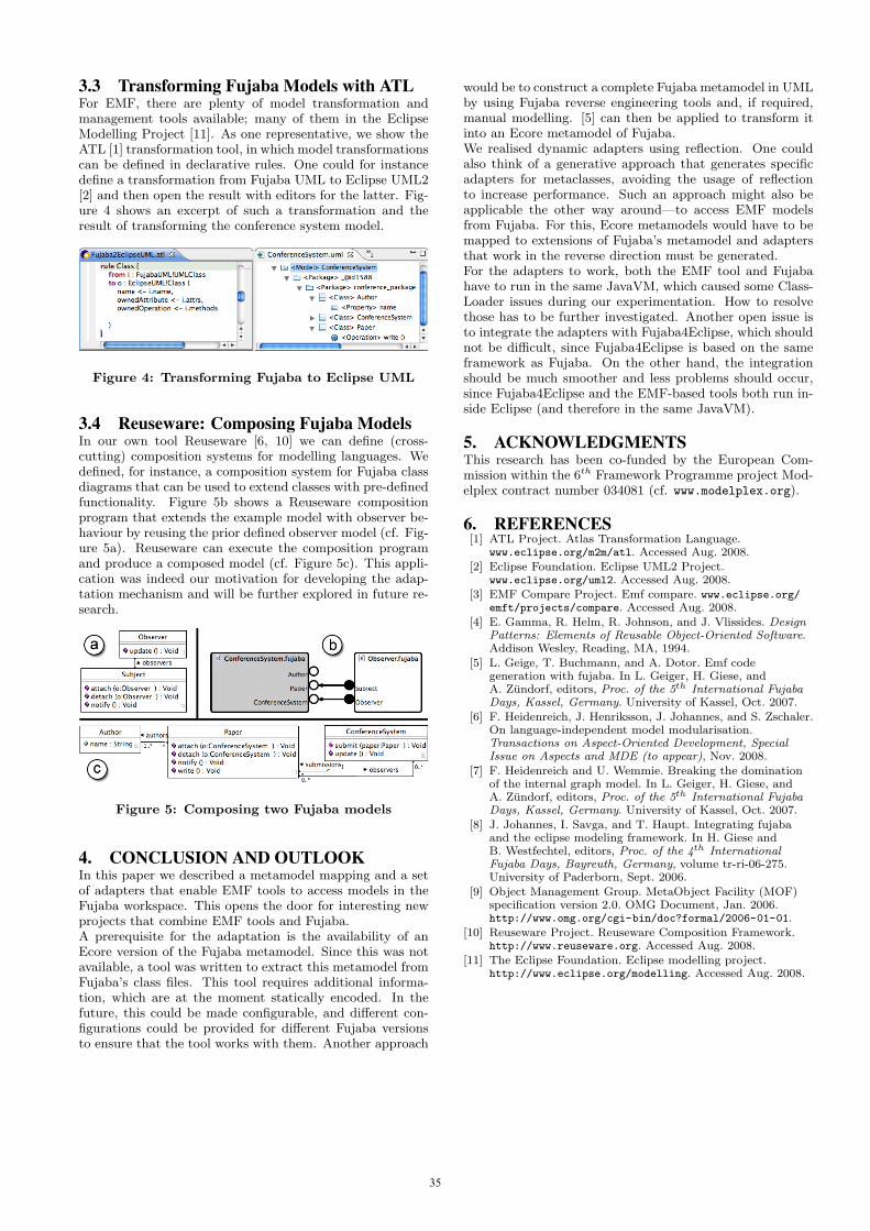
3.3 Transforming Fujaba Models with ATLFor EMF, there are plenty of model transformation andmanagement tools available; many of them in the EclipseModelling Project [11]. As one representative, we show theATL [1] transformation tool, in which model transformationscan be defined in declarative rules. One could for instancedefine a transformation from Fujaba UML to Eclipse UML2[2] and then open the result with editors for the latter. Fig-ure 4 shows an excerpt of such a transformation and theresult of transforming the conference system model.
Figure 4: Transforming Fujaba to Eclipse UML
3.4 Reuseware: Composing Fujaba ModelsIn our own tool Reuseware [6, 10] we can define (cross-cutting) composition systems for modelling languages. Wedefined, for instance, a composition system for Fujaba classdiagrams that can be used to extend classes with pre-definedfunctionality. Figure 5b shows a Reuseware compositionprogram that extends the example model with observer be-haviour by reusing the prior defined observer model (cf. Fig-ure 5a). Reuseware can execute the composition programand produce a composed model (cf. Figure 5c). This appli-cation was indeed our motivation for developing the adap-tation mechanism and will be further explored in future re-search.
Figure 5: Composing two Fujaba models
4. CONCLUSION AND OUTLOOKIn this paper we described a metamodel mapping and a setof adapters that enable EMF tools to access models in theFujaba workspace. This opens the door for interesting newprojects that combine EMF tools and Fujaba.A prerequisite for the adaptation is the availability of anEcore version of the Fujaba metamodel. Since this was notavailable, a tool was written to extract this metamodel fromFujaba’s class files. This tool requires additional informa-tion, which are at the moment statically encoded. In thefuture, this could be made configurable, and different con-figurations could be provided for different Fujaba versionsto ensure that the tool works with them. Another approach
would be to construct a complete Fujaba metamodel in UMLby using Fujaba reverse engineering tools and, if required,manual modelling. [5] can then be applied to transform itinto an Ecore metamodel of Fujaba.We realised dynamic adapters using reflection. One couldalso think of a generative approach that generates specificadapters for metaclasses, avoiding the usage of reflectionto increase performance. Such an approach might also beapplicable the other way around—to access EMF modelsfrom Fujaba. For this, Ecore metamodels would have to bemapped to extensions of Fujaba’s metamodel and adaptersthat work in the reverse direction must be generated.For the adapters to work, both the EMF tool and Fujabahave to run in the same JavaVM, which caused some Class-Loader issues during our experimentation. How to resolvethose has to be further investigated. Another open issue isto integrate the adapters with Fujaba4Eclipse, which shouldnot be difficult, since Fujaba4Eclipse is based on the sameframework as Fujaba. On the other hand, the integrationshould be much smoother and less problems should occur,since Fujaba4Eclipse and the EMF-based tools both run in-side Eclipse (and therefore in the same JavaVM).
5. ACKNOWLEDGMENTSThis research has been co-funded by the European Com-mission within the 6th Framework Programme project Mod-elplex contract number 034081 (cf. www.modelplex.org).
6. REFERENCES[1] ATL Project. Atlas Transformation Language.
www.eclipse.org/m2m/atl. Accessed Aug. 2008.
[2] Eclipse Foundation. Eclipse UML2 Project.www.eclipse.org/uml2. Accessed Aug. 2008.
[3] EMF Compare Project. Emf compare. www.eclipse.org/emft/projects/compare. Accessed Aug. 2008.
[4] E. Gamma, R. Helm, R. Johnson, and J. Vlissides. DesignPatterns: Elements of Reusable Object-Oriented Software.Addison Wesley, Reading, MA, 1994.
[5] L. Geige, T. Buchmann, and A. Dotor. Emf codegeneration with fujaba. In L. Geiger, H. Giese, andA. Zundorf, editors, Proc. of the 5th International FujabaDays, Kassel, Germany. University of Kassel, Oct. 2007.
[6] F. Heidenreich, J. Henriksson, J. Johannes, and S. Zschaler.On language-independent model modularisation.Transactions on Aspect-Oriented Development, SpecialIssue on Aspects and MDE (to appear), Nov. 2008.
[7] F. Heidenreich and U. Wemmie. Breaking the dominationof the internal graph model. In L. Geiger, H. Giese, andA. Zundorf, editors, Proc. of the 5th International FujabaDays, Kassel, Germany. University of Kassel, Oct. 2007.
[8] J. Johannes, I. Savga, and T. Haupt. Integrating fujabaand the eclipse modeling framework. In H. Giese andB. Westfechtel, editors, Proc. of the 4th InternationalFujaba Days, Bayreuth, Germany, volume tr-ri-06-275.University of Paderborn, Sept. 2006.
[9] Object Management Group. MetaObject Facility (MOF)specification version 2.0. OMG Document, Jan. 2006.http://www.omg.org/cgi-bin/doc?formal/2006-01-01.
[10] Reuseware Project. Reuseware Composition Framework.http://www.reuseware.org. Accessed Aug. 2008.
[11] The Eclipse Foundation. Eclipse modelling project.http://www.eclipse.org/modelling. Accessed Aug. 2008.
35
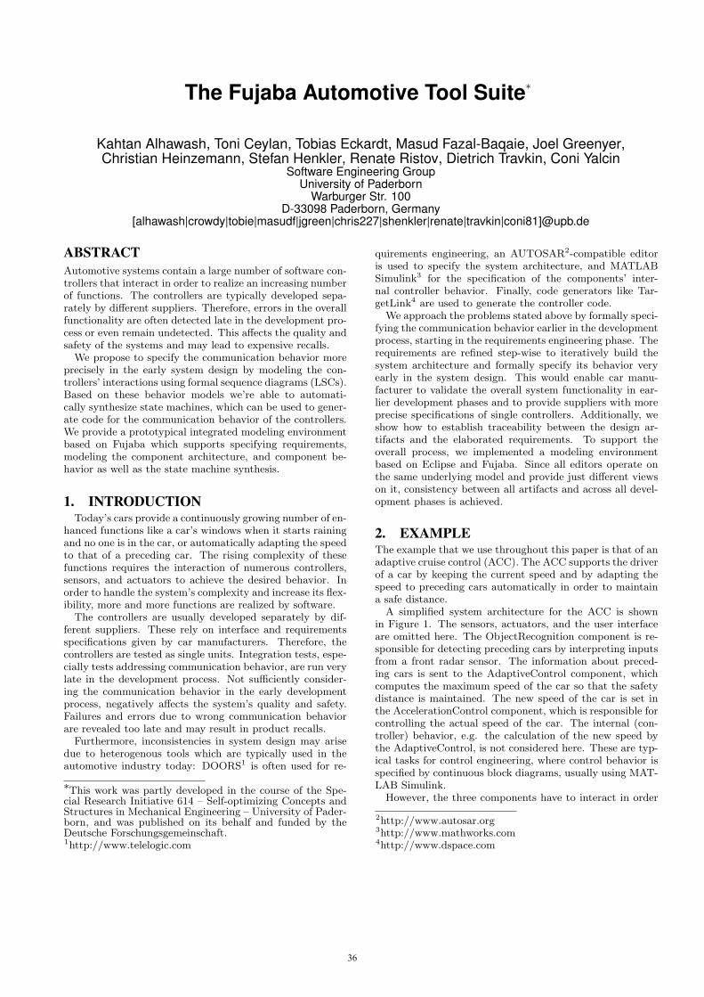
The Fujaba Automotive Tool Suite∗
Kahtan Alhawash, Toni Ceylan, Tobias Eckardt, Masud Fazal-Baqaie, Joel Greenyer,Christian Heinzemann, Stefan Henkler, Renate Ristov, Dietrich Travkin, Coni Yalcin
Software Engineering GroupUniversity of Paderborn
Warburger Str. 100D-33098 Paderborn, Germany
[alhawash|crowdy|tobie|masudf|jgreen|chris227|shenkler|renate|travkin|coni81]@upb.de
ABSTRACTAutomotive systems contain a large number of software con-trollers that interact in order to realize an increasing numberof functions. The controllers are typically developed sepa-rately by different suppliers. Therefore, errors in the overallfunctionality are often detected late in the development pro-cess or even remain undetected. This affects the quality andsafety of the systems and may lead to expensive recalls.
We propose to specify the communication behavior moreprecisely in the early system design by modeling the con-trollers’ interactions using formal sequence diagrams (LSCs).Based on these behavior models we’re able to automati-cally synthesize state machines, which can be used to gener-ate code for the communication behavior of the controllers.We provide a prototypical integrated modeling environmentbased on Fujaba which supports specifying requirements,modeling the component architecture, and component be-havior as well as the state machine synthesis.
1. INTRODUCTIONToday’s cars provide a continuously growing number of en-
hanced functions like a car’s windows when it starts rainingand no one is in the car, or automatically adapting the speedto that of a preceding car. The rising complexity of thesefunctions requires the interaction of numerous controllers,sensors, and actuators to achieve the desired behavior. Inorder to handle the system’s complexity and increase its flex-ibility, more and more functions are realized by software.
The controllers are usually developed separately by dif-ferent suppliers. These rely on interface and requirementsspecifications given by car manufacturers. Therefore, thecontrollers are tested as single units. Integration tests, espe-cially tests addressing communication behavior, are run verylate in the development process. Not sufficiently consider-ing the communication behavior in the early developmentprocess, negatively affects the system’s quality and safety.Failures and errors due to wrong communication behaviorare revealed too late and may result in product recalls.
Furthermore, inconsistencies in system design may arisedue to heterogenous tools which are typically used in theautomotive industry today: DOORS1 is often used for re-
∗This work was partly developed in the course of the Spe-cial Research Initiative 614 – Self-optimizing Concepts andStructures in Mechanical Engineering – University of Pader-born, and was published on its behalf and funded by theDeutsche Forschungsgemeinschaft.1http://www.telelogic.com
quirements engineering, an AUTOSAR2-compatible editoris used to specify the system architecture, and MATLABSimulink3 for the specification of the components’ inter-nal controller behavior. Finally, code generators like Tar-getLink4 are used to generate the controller code.
We approach the problems stated above by formally speci-fying the communication behavior earlier in the developmentprocess, starting in the requirements engineering phase. Therequirements are refined step-wise to iteratively build thesystem architecture and formally specify its behavior veryearly in the system design. This would enable car manu-facturer to validate the overall system functionality in ear-lier development phases and to provide suppliers with moreprecise specifications of single controllers. Additionally, weshow how to establish traceability between the design ar-tifacts and the elaborated requirements. To support theoverall process, we implemented a modeling environmentbased on Eclipse and Fujaba. Since all editors operate onthe same underlying model and provide just different viewson it, consistency between all artifacts and across all devel-opment phases is achieved.
2. EXAMPLEThe example that we use throughout this paper is that of anadaptive cruise control (ACC). The ACC supports the driverof a car by keeping the current speed and by adapting thespeed to preceding cars automatically in order to maintaina safe distance.
A simplified system architecture for the ACC is shownin Figure 1. The sensors, actuators, and the user interfaceare omitted here. The ObjectRecognition component is re-sponsible for detecting preceding cars by interpreting inputsfrom a front radar sensor. The information about preced-ing cars is sent to the AdaptiveControl component, whichcomputes the maximum speed of the car so that the safetydistance is maintained. The new speed of the car is set inthe AccelerationControl component, which is responsible forcontrolling the actual speed of the car. The internal (con-troller) behavior, e.g. the calculation of the new speed bythe AdaptiveControl, is not considered here. These are typ-ical tasks for control engineering, where control behavior isspecified by continuous block diagrams, usually using MAT-LAB Simulink.
However, the three components have to interact in order
2http://www.autosar.org3http://www.mathworks.com4http://www.dspace.com
36
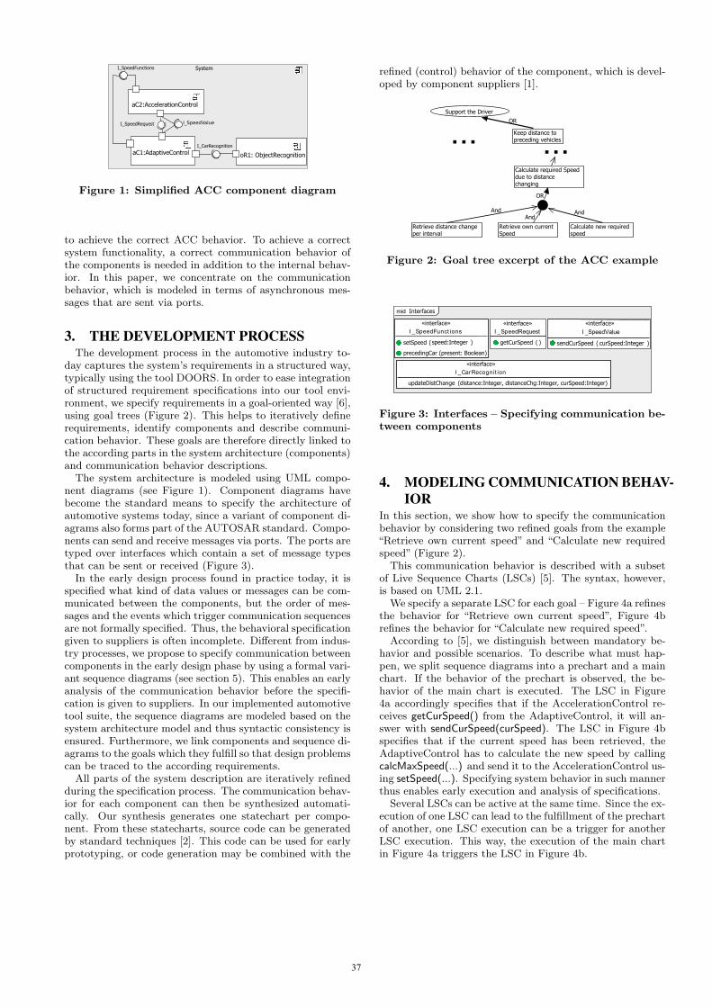
Figure 1: Simplified ACC component diagram
to achieve the correct ACC behavior. To achieve a correctsystem functionality, a correct communication behavior ofthe components is needed in addition to the internal behav-ior. In this paper, we concentrate on the communicationbehavior, which is modeled in terms of asynchronous mes-sages that are sent via ports.
3. THE DEVELOPMENT PROCESSThe development process in the automotive industry to-
day captures the system’s requirements in a structured way,typically using the tool DOORS. In order to ease integrationof structured requirement specifications into our tool envi-ronment, we specify requirements in a goal-oriented way [6],using goal trees (Figure 2). This helps to iteratively definerequirements, identify components and describe communi-cation behavior. These goals are therefore directly linked tothe according parts in the system architecture (components)and communication behavior descriptions.
The system architecture is modeled using UML compo-nent diagrams (see Figure 1). Component diagrams havebecome the standard means to specify the architecture ofautomotive systems today, since a variant of component di-agrams also forms part of the AUTOSAR standard. Compo-nents can send and receive messages via ports. The ports aretyped over interfaces which contain a set of message typesthat can be sent or received (Figure 3).
In the early design process found in practice today, it isspecified what kind of data values or messages can be com-municated between the components, but the order of mes-sages and the events which trigger communication sequencesare not formally specified. Thus, the behavioral specificationgiven to suppliers is often incomplete. Different from indus-try processes, we propose to specify communication betweencomponents in the early design phase by using a formal vari-ant sequence diagrams (see section 5). This enables an earlyanalysis of the communication behavior before the specifi-cation is given to suppliers. In our implemented automotivetool suite, the sequence diagrams are modeled based on thesystem architecture model and thus syntactic consistency isensured. Furthermore, we link components and sequence di-agrams to the goals which they fulfill so that design problemscan be traced to the according requirements.
All parts of the system description are iteratively refinedduring the specification process. The communication behav-ior for each component can then be synthesized automati-cally. Our synthesis generates one statechart per compo-nent. From these statecharts, source code can be generatedby standard techniques [2]. This code can be used for earlyprototyping, or code generation may be combined with the
refined (control) behavior of the component, which is devel-oped by component suppliers [1].
Keep distance to preceding vehicles
Support the Driver
Calculate new required speed
Retrieve own current Speed
Calculate required Speed due to distance changing
Retrieve distance change per interval
OR
OR
AndAnd And
......
Figure 2: Goal tree excerpt of the ACC example
«interface»I _SpeedFunct ions
setSpeed (speed:Integer )
«interface»I _CarRecognit ion
updateDistChange (
mid Interfaces
«interface»I _SpeedRequest
getCurSpeed ( )
«interface»I _SpeedValue
sendCurSpeed ( curSpeed:Integer )
distance:Integer, distanceChg:Integer, curSpeed:Integer)
precedingCar (present: Boolean)
Figure 3: Interfaces – Specifying communication be-tween components
4. MODELING COMMUNICATION BEHAV-IOR
In this section, we show how to specify the communicationbehavior by considering two refined goals from the example“Retrieve own current speed” and “Calculate new requiredspeed” (Figure 2).
This communication behavior is described with a subsetof Live Sequence Charts (LSCs) [5]. The syntax, however,is based on UML 2.1.
We specify a separate LSC for each goal – Figure 4a refinesthe behavior for “Retrieve own current speed”, Figure 4brefines the behavior for “Calculate new required speed”.
According to [5], we distinguish between mandatory be-havior and possible scenarios. To describe what must hap-pen, we split sequence diagrams into a prechart and a mainchart. If the behavior of the prechart is observed, the be-havior of the main chart is executed. The LSC in Figure4a accordingly specifies that if the AccelerationControl re-ceives getCurSpeed() from the AdaptiveControl, it will an-swer with sendCurSpeed(curSpeed). The LSC in Figure 4bspecifies that if the current speed has been retrieved, theAdaptiveControl has to calculate the new speed by callingcalcMaxSpeed(...) and send it to the AccelerationControl us-ing setSpeed(...). Specifying system behavior in such mannerthus enables early execution and analysis of specifications.
Several LSCs can be active at the same time. Since the ex-ecution of one LSC can lead to the fulfillment of the prechartof another, one LSC execution can be a trigger for anotherLSC execution. This way, the execution of the main chartin Figure 4a triggers the LSC in Figure 4b.
37
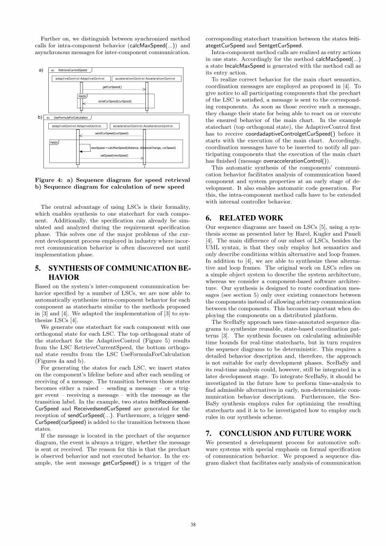
Further on, we distinguish between synchronized methodcalls for intra-component behavior (calcMaxSpeed(...)) andasynchronous messages for inter-component communication.
sc RetrieveCurrentSpeed
adapt iveCont rol:Adapt iveCont rol accelerat ionCont rol:Accelerat ionCont rol
MAINMAIN
getCurSpeed()
sendCurSpeed(curSpeed)
sc UseFormulaForCalculation
accelerat ionCont rol:Accelerat ionCont roladapt iveCont rol:Adapt iveCont rol
MAINMAIN
setSpeed(newSpeed)
sendCurSpeed(curSpeed)
calcMaxSpeed(distance, distanceChange, curSpeed)newSpeed:=
a)
b)
Figure 4: a) Sequence diagram for speed retrievalb) Sequence diagram for calculation of new speed
The central advantage of using LSCs is their formality,which enables synthesis to one statechart for each compo-nent. Additionally, the specification can already be sim-ulated and analyzed during the requirement specificationphase. This solves one of the major problems of the cur-rent development process employed in industry where incor-rect communication behavior is often discovered not untilimplementation phase.
5. SYNTHESIS OF COMMUNICATION BE-HAVIOR
Based on the system’s inter-component communication be-havior specified by a number of LSCs, we are now able toautomatically synthesize intra-component behavior for eachcomponent as statecharts similar to the methods proposedin [3] and [4]. We adapted the implementation of [3] to syn-thesize LSCs [4].
We generate one statechart for each component with oneorthogonal state for each LSC. The top orthogonal state ofthe statechart for the AdaptiveControl (Figure 5) resultsfrom the LSC RetrieveCurrentSpeed, the bottom orthogo-nal state results from the LSC UseFormulaForCalculation(Figures 4a and b).
For generating the states for each LSC, we insert stateson the component’s lifeline before and after each sending orreceiving of a message. The transition between those statesbecomes either a raised – sending a message – or a trig-ger event – receiving a message – with the message as thetransition label. In the example, two states InitReceivesend-CurSpeed and ReceivedsendCurSpeed are generated for thereception of sendCurSpeed(...). Furthermore, a trigger send-CurSpeed(curSpeed) is added to the transition between thosestates.
If the message is located in the prechart of the sequencediagram, the event is always a trigger, whether the messageis sent or received. The reason for this is that the prechartis observed behavior and not executed behavior. In the ex-ample, the sent message getCurSpeed() is a trigger of the
corresponding statechart transition between the states Initi-ategetCurSpeed and SentgetCurSpeed.
Intra-component method calls are realized as entry actionsin one state. Accordingly for the method calcMaxSpeed(...)a state IncalcMaxSpeed is generated with the method call asits entry action.
To realize correct behavior for the main chart semantics,coordination messages are employed as proposed in [4]. Togive notice to all participating components that the prechartof the LSC is satisfied, a message is sent to the correspond-ing components. As soon as those receive such a message,they change their state for being able to react on or executethe ensured behavior of the main chart. In the examplestatechart (top orthogonal state), the AdaptiveControl firsthas to receive coordadaptiveControlgetCurSpeed() before itstarts with the execution of the main chart. Accordingly,coordination messages have to be inserted to notify all par-ticipating components that the execution of the main charthas finished (message overaccelerationControl()).
This automatic synthesis of the components’ communi-cation behavior facilitates analysis of communication basedcomponent and system properties at an early stage of de-velopment. It also enables automatic code generation. Forthis, the intra-component method calls have to be extendedwith internal controller behavior.
6. RELATED WORKOur sequence diagrams are based on LSCs [5], using a syn-thesis sceme as presented later by Harel, Kugler and Pnueli[4]. The main difference of our subset of LSCs, besides theUML syntax, is that they only employ hot semantics andonly describe conditions within alternative and loop frames.In addition to [4], we are able to synthesize these alterna-tive and loop frames. The original work on LSCs relies ona simple object system to describe the system architecture,whereas we consider a component-based software architec-ture. Our synthesis is designed to route coordination mes-sages (see section 5) only over existing connectors betweenthe components instead of allowing arbitrary communicationbetween the components. This becomes important when de-ploying the components on a distributed platform.
The SceBaSy approach uses time-annotated sequence dia-grams to synthesize reusable, state-based coordination pat-terns [3]. The synthesis focuses on calculating admissibletime bounds for real-time statecharts, but in turn requiresthe sequence diagrams to be deterministic. This requires adetailed behavior description and, therefore, the approachis not suitable for early development phases. SceBaSy andits real-time analysis could, however, still be integrated in alater development stage. To integrate SceBaSy, it should beinvestigated in the future how to perform time-analysis tofind admissible alternatives in early, non-deterministic com-munication behavior descriptions. Furthermore, the Sce-BaSy synthesis employs rules for optimizing the resultingstatecharts and it is to be investigated how to employ suchrules in our synthesis scheme.
7. CONCLUSION AND FUTURE WORKWe presented a development process for automotive soft-ware systems with special emphasis on formal specificationof communication behavior. We proposed a sequence dia-gram dialect that facilitates early analysis of communication
38

adaptiveControl
InitiategetCurSpeed SentgetCurSpeed
InitiateoveraccelerationControl
SentoveraccelerationControl
InitReceivesendCurSpeedReceivedsendCurSpeed
InitReceivecoordadaptiveControlgetCurSpeed
ReceivedcoordadaptiveControlgetCurSpeed
InitialState
calcMaxSpeed
InitiatecoordaccelerationControlsendCurSpeed
SentcoordaccelerationControlsendCurSpeedInitiatesendSpeed
SentsendSpeed
InitReceivesendCurSpeed ReceivedsendCurSpeed
InitReceiveoveradaptiveControl
ReceivedoveradaptiveControl
InitialState
1
0
Trigger:getCurSpeed()
1
1
1
Raised:overaccelerationControl()
1
Trigger:sendCurSpeed(curSpeed)
1
Trigger:coordadaptiveControlgetCurSpeed()
1
0
1
1
Raised:sendSpeed(speed) 1
Trigger:sendCurSpeed(curSpeed)
Trigger:overadaptiveControl()
0
InitialState
In
calcMaxSpeed(distance, distChange, curSpeed)entry:
1
1
1
1
1
Raised:coordaccelerationControlsendCurSpeed()
11
Figure 5: Synthesised statechart for the adaptiveControl component
behavior and automatic synthesis to communication basedcomponent behavior by means of statecharts. We realizedtool support for this development process and proposed con-cepts using the Fujaba4Eclipse platform.
Future work embraces scalablity analysis of the synthe-sized statecharts. We suppose that, as the approach usesparallel states, it provides better scalability for statechartsthan synthesizing one non-parallel statechart for each com-ponent. Accordingly, synthesized statecharts should be op-timized to eliminate superfluous states.
Also important for future work are consistency checks onLSCs, for example showing deadlock freedom or discoveringcontradictions between several LSCs. This is important, be-cause a high modularity in the LSC specification can leadto many inconsistency that are not obvious to see.
It is already possible to annotate time constraints in ourLSCs. The synthesis approach needs to be extended withtiming analysis as the specified systems act in real-time envi-ronments. One possibility could be to integrate SceBaSy foruse in later design phases of the overall development processwhile using our approach in the requirement specification.Controller behavior has to be integrated for example usingMATLAB Simulink models. Another extension could be theinclusion of a deployment model (cf. AUTOSAR) in orderto specify which software components shall be realized onwhich hardware components. Finally, an AUTOSAR con-form code generation should be developed to support theimplementation phase of the automotive software system.
8. REFERENCES[1] S. Burmester, H. Giese, S. Henkler, M. Hirsch,
M. Tichy, A. Gambuzza, E. Much, and H. Vocking.Tool support for developing advanced mechatronicsystems: Integrating the fujaba real-time tool suite
with camel-view. In Proc. of the 29th InternationalConference on Software Engineering (ICSE),Minneapolis, Minnesota, USA, pages 801–804. IEEEComputer Society Press, May 2007.
[2] S. Burmester, H. Giese, and W. Schafer. Codegeneration for hard real-time systems from real-timestatecharts. Technical Report tr-ri-03-244, University ofPaderborn, Paderborn, Germany, October 2003.
[3] H. Giese, S. Henkler, M. Hirsch, and F. Klein.Nobody’s perfect: interactive synthesis fromparametrized real-time scenarios. In SCESM ’06:Proceedings of the 2006 international workshop onScenarios and state machines: models, algorithms, andtools, pages 67–74, New York, NY, USA, 2006. ACM.
[4] D. Harel, H. Kugler, and A. Pnueli. Synthesis revisited:Generating statechart models from scenario-basedrequirements. In Formal Methods in Software andSystems Modeling, pages 309–324, Berlin/Heidelberg,Germany, 2005. Springer-Verlag.
[5] D. Harel and R. Marelly. Come, Let’s Play:Scenario-Based Programming Using LSC’s and thePlay-Engine. Springer-Verlag New York, Inc., Secaucus,NJ, USA, 2003.
[6] A. V. Lamsweerde. Goal-oriented requirementsengineering: A guided tour. RE ’01: Proceedings of the5th IEEE International Symposium on RequirementsEngineering, page 249, 2001.
39
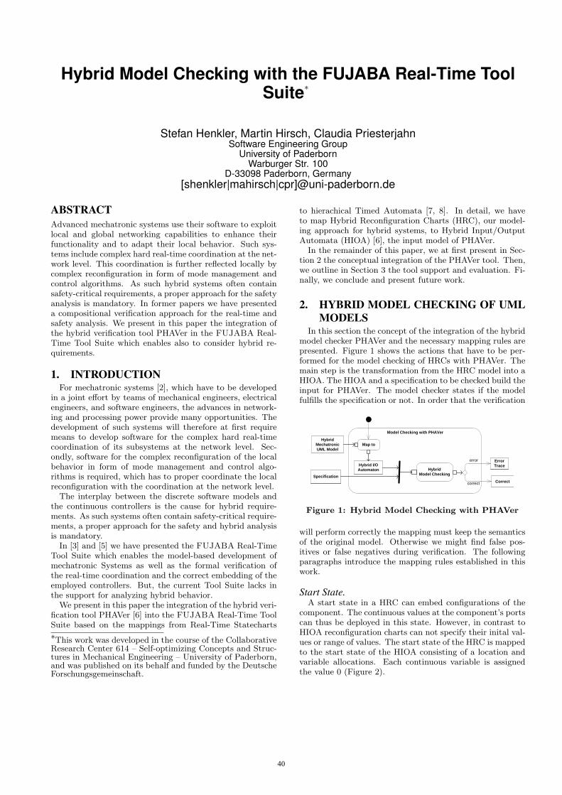
Hybrid Model Checking with the FUJABA Real-Time ToolSuite∗
Stefan Henkler, Martin Hirsch, Claudia PriesterjahnSoftware Engineering Group
University of PaderbornWarburger Str. 100
D-33098 Paderborn, Germany[shenkler|mahirsch|cpr]@uni-paderborn.de
ABSTRACTAdvanced mechatronic systems use their software to exploitlocal and global networking capabilities to enhance theirfunctionality and to adapt their local behavior. Such sys-tems include complex hard real-time coordination at the net-work level. This coordination is further reflected locally bycomplex reconfiguration in form of mode management andcontrol algorithms. As such hybrid systems often containsafety-critical requirements, a proper approach for the safetyanalysis is mandatory. In former papers we have presenteda compositional verification approach for the real-time andsafety analysis. We present in this paper the integration ofthe hybrid verification tool PHAVer in the FUJABA Real-Time Tool Suite which enables also to consider hybrid re-quirements.
1. INTRODUCTIONFor mechatronic systems [2], which have to be developed
in a joint effort by teams of mechanical engineers, electricalengineers, and software engineers, the advances in network-ing and processing power provide many opportunities. Thedevelopment of such systems will therefore at first requiremeans to develop software for the complex hard real-timecoordination of its subsystems at the network level. Sec-ondly, software for the complex reconfiguration of the localbehavior in form of mode management and control algo-rithms is required, which has to proper coordinate the localreconfiguration with the coordination at the network level.
The interplay between the discrete software models andthe continuous controllers is the cause for hybrid require-ments. As such systems often contain safety-critical require-ments, a proper approach for the safety and hybrid analysisis mandatory.
In [3] and [5] we have presented the FUJABA Real-TimeTool Suite which enables the model-based development ofmechatronic Systems as well as the formal verification ofthe real-time coordination and the correct embedding of theemployed controllers. But, the current Tool Suite lacks inthe support for analyzing hybrid behavior.
We present in this paper the integration of the hybrid veri-fication tool PHAVer [6] into the FUJABA Real-Time ToolSuite based on the mappings from Real-Time Statecharts
∗This work was developed in the course of the CollaborativeResearch Center 614 – Self-optimizing Concepts and Struc-tures in Mechanical Engineering – University of Paderborn,and was published on its behalf and funded by the DeutscheForschungsgemeinschaft.
to hierachical Timed Automata [7, 8]. In detail, we haveto map Hybrid Reconfiguration Charts (HRC), our model-ing approach for hybrid systems, to Hybrid Input/OutputAutomata (HIOA) [6], the input model of PHAVer.
In the remainder of this paper, we at first present in Sec-tion 2 the conceptual integration of the PHAVer tool. Then,we outline in Section 3 the tool support and evaluation. Fi-nally, we conclude and present future work.
2. HYBRID MODEL CHECKING OF UMLMODELS
In this section the concept of the integration of the hybridmodel checker PHAVer and the necessary mapping rules arepresented. Figure 1 shows the actions that have to be per-formed for the model checking of HRCs with PHAVer. Themain step is the transformation from the HRC model into aHIOA. The HIOA and a specification to be checked build theinput for PHAVer. The model checker states if the modelfulfills the specification or not. In order that the verification
Model Checking with PHAVer
Hybrid
Mechatronic
UML Model
Specification
Error
Trace
Correct
Hybrid I/O
Automaton Hybrid
Model Checking
Map to
correct
error
Figure 1: Hybrid Model Checking with PHAVer
will perform correctly the mapping must keep the semanticsof the original model. Otherwise we might find false pos-itives or false negatives during verification. The followingparagraphs introduce the mapping rules established in thiswork.
Start State.A start state in a HRC can embed configurations of the
component. The continuous values at the component’s portscan thus be deployed in this state. However, in contrast toHIOA reconfiguration charts can not specify their inital val-ues or range of values. The start state of the HRC is mappedto the start state of the HIOA consisting of a location andvariable allocations. Each continuous variable is assignedthe value 0 (Figure 2).
40
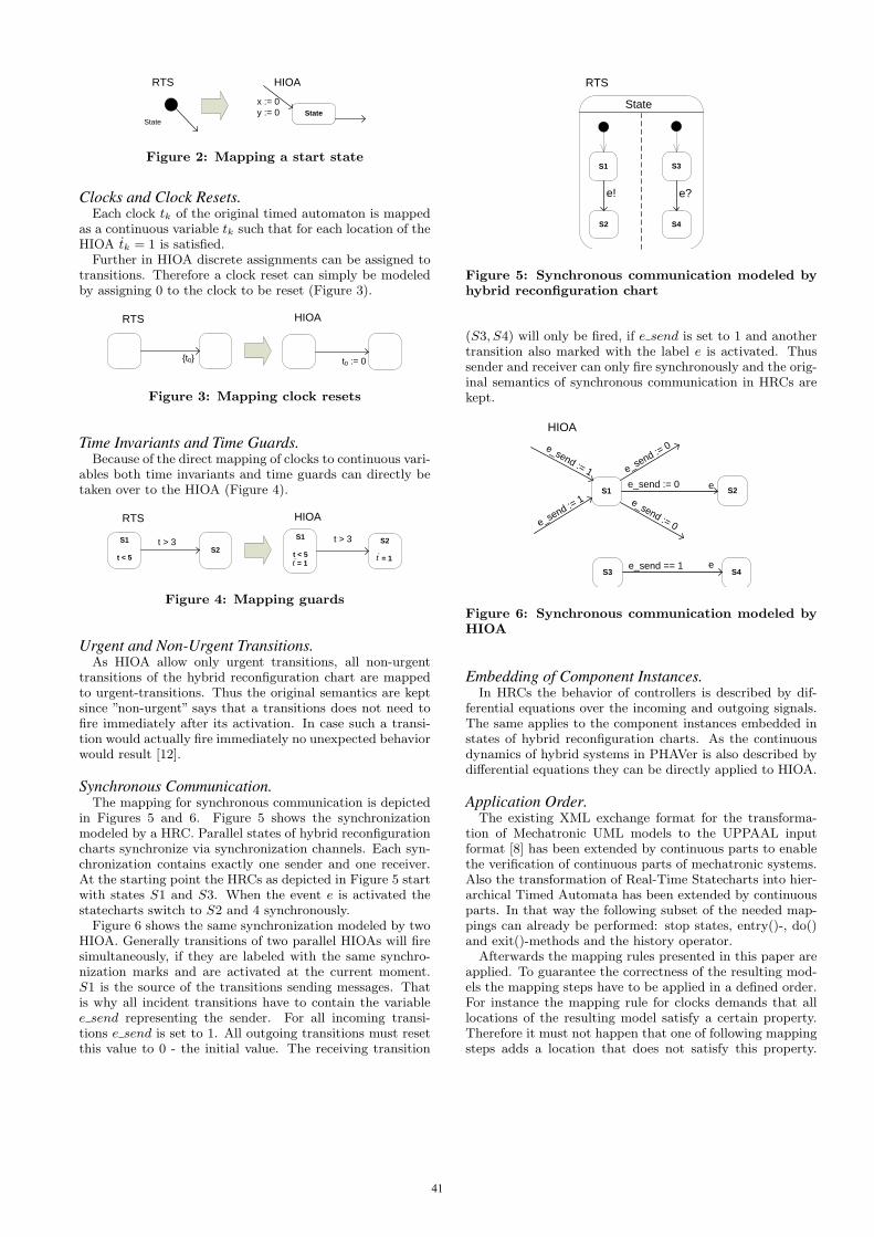
State
HIOA
State
RTS
x := 0
y := 0
Figure 2: Mapping a start state
Clocks and Clock Resets.Each clock tk of the original timed automaton is mapped
as a continuous variable tk such that for each location of theHIOA tk = 1 is satisfied.
Further in HIOA discrete assignments can be assigned totransitions. Therefore a clock reset can simply be modeledby assigning 0 to the clock to be reset (Figure 3).
HIOARTS
{t0} t0 := 0
Figure 3: Mapping clock resets
Time Invariants and Time Guards.Because of the direct mapping of clocks to continuous vari-
ables both time invariants and time guards can directly betaken over to the HIOA (Figure 4).
HIOARTS
S1
t < 5S2
t > 3S1
t < 5
= 1
S2
= 1
t > 3
tt
Figure 4: Mapping guards
Urgent and Non-Urgent Transitions.As HIOA allow only urgent transitions, all non-urgent
transitions of the hybrid reconfiguration chart are mappedto urgent-transitions. Thus the original semantics are keptsince ”non-urgent” says that a transitions does not need tofire immediately after its activation. In case such a transi-tion would actually fire immediately no unexpected behaviorwould result [12].
Synchronous Communication.The mapping for synchronous communication is depicted
in Figures 5 and 6. Figure 5 shows the synchronizationmodeled by a HRC. Parallel states of hybrid reconfigurationcharts synchronize via synchronization channels. Each syn-chronization contains exactly one sender and one receiver.At the starting point the HRCs as depicted in Figure 5 startwith states S1 and S3. When the event e is activated thestatecharts switch to S2 and 4 synchronously.
Figure 6 shows the same synchronization modeled by twoHIOA. Generally transitions of two parallel HIOAs will firesimultaneously, if they are labeled with the same synchro-nization marks and are activated at the current moment.S1 is the source of the transitions sending messages. Thatis why all incident transitions have to contain the variablee send representing the sender. For all incoming transi-tions e send is set to 1. All outgoing transitions must resetthis value to 0 - the initial value. The receiving transition
S1
S2
S3
S4
e! e?
State
RTS
Figure 5: Synchronous communication modeled byhybrid reconfiguration chart
(S3, S4) will only be fired, if e send is set to 1 and anothertransition also marked with the label e is activated. Thussender and receiver can only fire synchronously and the orig-inal semantics of synchronous communication in HRCs arekept.
S1 S2
S3 S4
HIOA
e_send := 1
e_send := 1
e_send := 0
e_send := 0
e_send := 0
e_send == 1
e
e
Figure 6: Synchronous communication modeled byHIOA
Embedding of Component Instances.In HRCs the behavior of controllers is described by dif-
ferential equations over the incoming and outgoing signals.The same applies to the component instances embedded instates of hybrid reconfiguration charts. As the continuousdynamics of hybrid systems in PHAVer is also described bydifferential equations they can be directly applied to HIOA.
Application Order.The existing XML exchange format for the transforma-
tion of Mechatronic UML models to the UPPAAL inputformat [8] has been extended by continuous parts to enablethe verification of continuous parts of mechatronic systems.Also the transformation of Real-Time Statecharts into hier-archical Timed Automata has been extended by continuousparts. In that way the following subset of the needed map-pings can already be performed: stop states, entry()-, do()and exit()-methods and the history operator.
Afterwards the mapping rules presented in this paper areapplied. To guarantee the correctness of the resulting mod-els the mapping steps have to be applied in a defined order.For instance the mapping rule for clocks demands that alllocations of the resulting model satisfy a certain property.Therefore it must not happen that one of following mappingsteps adds a location that does not satisfy this property.
41
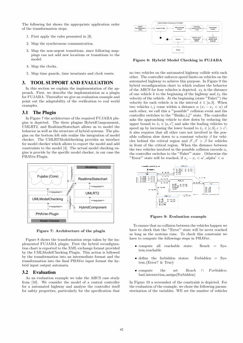
The following list shows the appropriate application orderof the transformation steps.
1. First apply the rules presented in [8].
2. Map the synchronous communication.
3. Map the non-urgent transitions, since following map-pings can not add new locations or transitions to themodel.
4. Map the clocks.
5. Map time guards, time invariants and clock resets.
3. TOOL SUPPORT AND EVALUATIONIn this section we explain the implementation of the ap-
proach. First, we describe the implementation as a pluginfor FUJABA. Thereafter we give an evaluation example andpoint out the adaptability of the verification to real worldexamples.
3.1 The PluginIn Figure 7 the architecture of the required FUJABA plu-
gins is depicted. The three plugins HybridComponenent,UMLRT2, and RealtimeStatechart allows us to model thebehavior as well as the structure of hybrid systems. The plu-gins on the bottom left side realize the integration of modelchecker. The UMLRTModelchecking provides an interfacefor model checker which allows to export the model and addconstraints to the model [4]. The actual model checking en-gine is provide by the specific model checker, in our case thePHAVer-Plugin.
<<requires>>
<<requires>>
<<requires>>
<<requires>>
<<requires>>
<<requires>>
<<requires>>
Modeling
Model Checker
Figure 7: Architecture of the plugin
Figure 8 shows the transformation steps taken by the im-plemented FUJABA plugin. First the hybrid reconfigura-tion chart is exported to the XML exchange format providedby the UMLModelChecking Plugin. This action is followedby the transformation into an intermediate format and thetransformation into the final PHAVer input format the hy-brid input output automata.
3.2 EvaluationAs an evaluation example we take the AHCS case study
from [10]. We consider the model of a central controllerfor a automated highway and analyze the controller itselffor safety properties, particularly for the specification that
Hybrid
Reconfiguration
Chart
XML Exchange
Format
PHAVer Input
Language
(HIOA)
Intermediate
Format
Result
Export to XML
PHAVerTransform to
PHAVer input
language
Transform
based on RTSC
-> HTA
Hybrid Model Checking in FUJABA
Figure 8: Hybrid Model Checking in FUJABA
no two vehicles on the automated highway collide with eachother. The controller enforces speed limits on vehicles on theautomated highway to achieve this purpose. In Figure 9 thehybrid reconfiguration chart to which realizes the behaviorof the AHCS for four vehicles is depicted. xk is the distanceof one vehicle k to the beginning of the highway and xk thevelocity of the vehicle. At the beginning (state ”‘Fahrt”’) thevelocity for each vehicle is in the interval x ∈ [a, b]. Whentwo vehicles i, j come within a distance α (xi − xj < α) ofeach other, we call this a ”‘possible”’ collision event and thecontroller switches to the ”‘Risiko i j”’ state. The controllerasks the approaching vehicle to slow down by reducing theupper bound to xi ∈ [a, c′] and asks the leading vehicles tospeed up by increasing the lower bound to xj ∈ [c, b], c > c′;it also requires that all other cars not involved in the pos-sible collision slow down to a constant velocity β for vehi-cles behind the critical region and β′, β′ > β for vehiclesin front of the critical region. When the distance betweenthe two vehicles involved in the possible collision exceeds α,the controller switches to the ”‘Fahrt”’ state . Otherwise the”‘Error”’ state will be reached, if xj − xi < α′, alpha′ < α
Figure 9: Evaluation example
To ensure that no collision between the vehicles happen wehave to check that the ”‘Error”’ state will be never reachedas long as the systems runs. To check this constraint wehave to compute the followings steps in PHAVer:
• compute all reachable state: Reach = Sys-tem.reachable
• define the forbidden states: Forbidden = Sys-tem.{Error? & True}
• compute the set Reach ∩ Forbidden:bad.intersection assign(Forbidden)
In Figure 10 a screenshot of the constraint is depicted. Forthe evaluation of the example, we chose the following param-eterization of the variables. WE set the number of vehicles
42
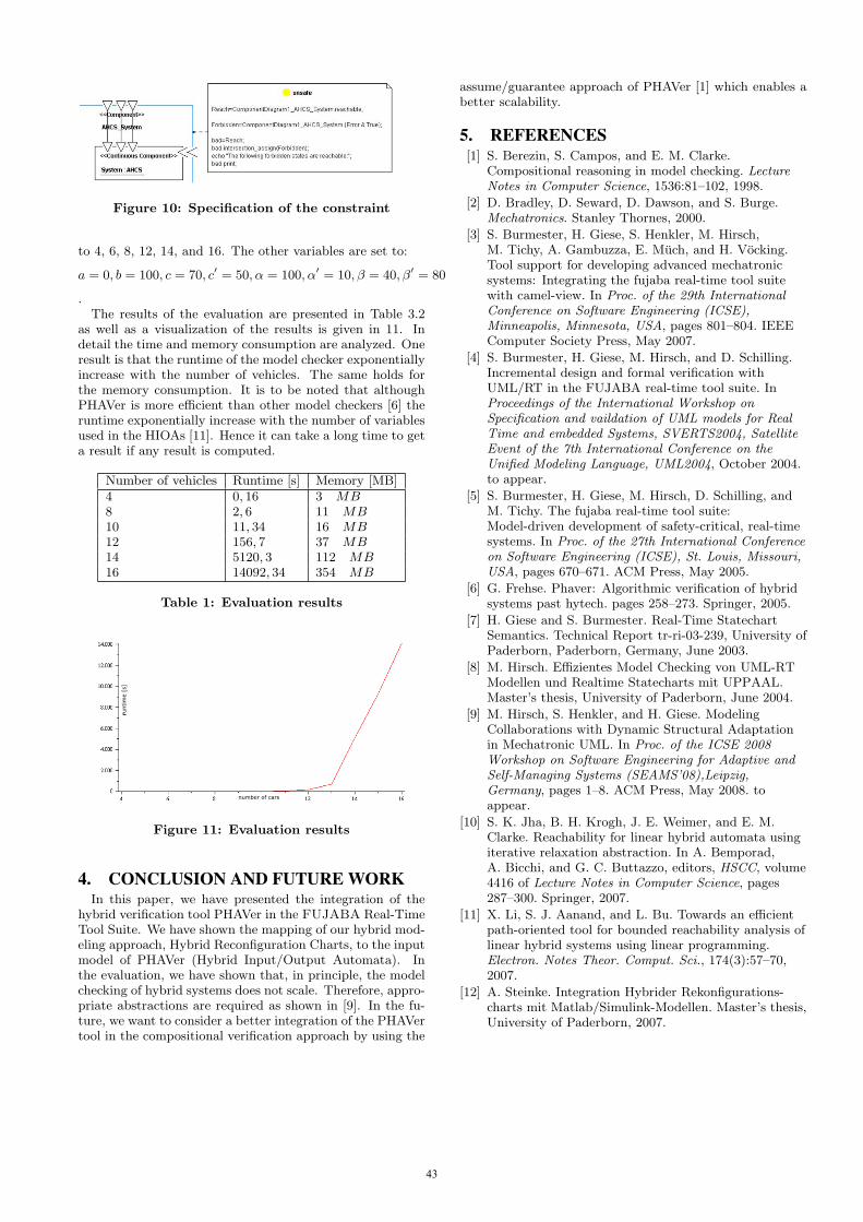
Figure 10: Specification of the constraint
to 4, 6, 8, 12, 14, and 16. The other variables are set to:
a = 0, b = 100, c = 70, c′ = 50, α = 100, α′ = 10, β = 40, β′ = 80
.The results of the evaluation are presented in Table 3.2
as well as a visualization of the results is given in 11. Indetail the time and memory consumption are analyzed. Oneresult is that the runtime of the model checker exponentiallyincrease with the number of vehicles. The same holds forthe memory consumption. It is to be noted that althoughPHAVer is more efficient than other model checkers [6] theruntime exponentially increase with the number of variablesused in the HIOAs [11]. Hence it can take a long time to geta result if any result is computed.
Number of vehicles Runtime [s] Memory [MB]4 0, 16 3 MB8 2, 6 11 MB10 11, 34 16 MB12 156, 7 37 MB14 5120, 3 112 MB16 14092, 34 354 MB
Table 1: Evaluation results
rruntim
e [s
]
number of cars
Figure 11: Evaluation results
4. CONCLUSION AND FUTURE WORKIn this paper, we have presented the integration of the
hybrid verification tool PHAVer in the FUJABA Real-TimeTool Suite. We have shown the mapping of our hybrid mod-eling approach, Hybrid Reconfiguration Charts, to the inputmodel of PHAVer (Hybrid Input/Output Automata). Inthe evaluation, we have shown that, in principle, the modelchecking of hybrid systems does not scale. Therefore, appro-priate abstractions are required as shown in [9]. In the fu-ture, we want to consider a better integration of the PHAVertool in the compositional verification approach by using the
assume/guarantee approach of PHAVer [1] which enables abetter scalability.
5. REFERENCES[1] S. Berezin, S. Campos, and E. M. Clarke.
Compositional reasoning in model checking. LectureNotes in Computer Science, 1536:81–102, 1998.
[2] D. Bradley, D. Seward, D. Dawson, and S. Burge.Mechatronics. Stanley Thornes, 2000.
[3] S. Burmester, H. Giese, S. Henkler, M. Hirsch,M. Tichy, A. Gambuzza, E. Much, and H. Vocking.Tool support for developing advanced mechatronicsystems: Integrating the fujaba real-time tool suitewith camel-view. In Proc. of the 29th InternationalConference on Software Engineering (ICSE),Minneapolis, Minnesota, USA, pages 801–804. IEEEComputer Society Press, May 2007.
[4] S. Burmester, H. Giese, M. Hirsch, and D. Schilling.Incremental design and formal verification withUML/RT in the FUJABA real-time tool suite. InProceedings of the International Workshop onSpecification and vaildation of UML models for RealTime and embedded Systems, SVERTS2004, SatelliteEvent of the 7th International Conference on theUnified Modeling Language, UML2004, October 2004.to appear.
[5] S. Burmester, H. Giese, M. Hirsch, D. Schilling, andM. Tichy. The fujaba real-time tool suite:Model-driven development of safety-critical, real-timesystems. In Proc. of the 27th International Conferenceon Software Engineering (ICSE), St. Louis, Missouri,USA, pages 670–671. ACM Press, May 2005.
[6] G. Frehse. Phaver: Algorithmic verification of hybridsystems past hytech. pages 258–273. Springer, 2005.
[7] H. Giese and S. Burmester. Real-Time StatechartSemantics. Technical Report tr-ri-03-239, University ofPaderborn, Paderborn, Germany, June 2003.
[8] M. Hirsch. Effizientes Model Checking von UML-RTModellen und Realtime Statecharts mit UPPAAL.Master’s thesis, University of Paderborn, June 2004.
[9] M. Hirsch, S. Henkler, and H. Giese. ModelingCollaborations with Dynamic Structural Adaptationin Mechatronic UML. In Proc. of the ICSE 2008Workshop on Software Engineering for Adaptive andSelf-Managing Systems (SEAMS’08),Leipzig,Germany, pages 1–8. ACM Press, May 2008. toappear.
[10] S. K. Jha, B. H. Krogh, J. E. Weimer, and E. M.Clarke. Reachability for linear hybrid automata usingiterative relaxation abstraction. In A. Bemporad,A. Bicchi, and G. C. Buttazzo, editors, HSCC, volume4416 of Lecture Notes in Computer Science, pages287–300. Springer, 2007.
[11] X. Li, S. J. Aanand, and L. Bu. Towards an efficientpath-oriented tool for bounded reachability analysis oflinear hybrid systems using linear programming.Electron. Notes Theor. Comput. Sci., 174(3):57–70,2007.
[12] A. Steinke. Integration Hybrider Rekonfigurations-charts mit Matlab/Simulink-Modellen. Master’s thesis,University of Paderborn, 2007.
43

Component Story Diagrams in Fujaba4Eclipse∗
Jörg Holtmann, Matthias TichySoftware Engineering Group
University of PaderbornWarburger Str. 100
D-33098 Paderborn, Germany[chrome|mtt]@uni-paderborn.de
ABSTRACTA current trend in Software Engineering is the develop-ment of self-adaptive component-based software architec-tures. Our modeling approach for component-based soft-ware systems Mechatronic UML, integrated in the Fu-jaba Real-Time Tool Suite plugin for Fujaba4Eclipse, sup-ports self-adaptiveness only to a certain degree. Thispaper presents tool support for an extension of Mecha-tronic UML, which facilitates initialization and reconfig-uration of a Mechatronic UML system based on StoryDiagrams and thus enables a step towards self-adaptivenesson a structural level.
1. INTRODUCTIONToday’s software systems are mainly build in a
component-based fashion to reduce their complexity. Fur-thermore, some software systems have to be self-adaptive,which means that they adapt their behavior in responseto event occurrences or changes in the environment. Theadaption can be realized by changing system parametersor by a structural reconfiguration. Mechatronic UML[1] supports, among other things, the modeling of compo-nents with real-time behavior, the coordination between dis-tributed components as well as its verification, but only alimited structural reconfiguration by enumerating all differ-ent configurations.
In [6], we presented concepts for an extension to Mecha-tronic UML, which overcomes this limitation. This pa-per presents the implementation of these concepts in Fu-jaba4Eclipse. The general idea is to use a formalism basedon Story Diagrams [2] to model system initialization and re-configuration for a component-based architecture. Compo-nent instance structures consist in contrast to object struc-tures of elements such as component and port instances anddifferent connector types. Furthermore, conventional StoryDiagrams operate only on flat object structures and do notprovide the possibility to traverse a hierarchy, which is in-duced by a component-based system. So traditional StoryDiagrams are not well suited for component-based archi-tectures, but their variant Component Story Diagrams [6]make use of both the Story Diagrams’ formal foundationsand sophisticated control structures as well as the exten-sions required by component-based architectures. The de-
∗This work was developed in the course of the CollaborativeResearch Center 614 – Self-optimizing Concepts and Struc-tures in Mechanical Engineering – University of Paderborn,and was published on its behalf and funded by the DeutscheForschungsgemeinschaft.
veloped formalism reuses the graphical syntax of componentdiagrams for a tight integration of the modeling of structureas well as reconfiguration behavior. We refer to [3, 6] for adiscussion of the limitations of related approaches.
The running example used in this paper is taken from [6]and describes the communication structure of autonomousrailway vehicles from the RailCab project1. These Rail-Cabs can build convoys to reduce the energy consumptionby utilizing the slipstream. Their communication structureis build by Mechatronic UML components. The lead-ing RailCab computes reference positions for all subsequentRailCabs in a convoy. For each following RailCab, one posi-tion calculation component is deployed in the leading Rail-Cab. This component sends the reference position to itsconnected following RailCab. Thus, a structural reconfigu-ration is required for the leading RailCab’s embedded com-ponents when a RailCab joins or leaves a convoy.
Section 2 sketches a flexible component type definitionas a base for the modeling of Component Story Diagrams.While Section 3 presents the Component Story Diagramsthemselves, Section 4 introduces the code generation plugin,which is a prerequisite for the execution of the ComponentStory Diagrams. Section 5 concludes this paper and adducescurrent and future work on Component Story Diagrams.
2. COMPONENT TYPE DEFINITIONLike conventional Story Diagrams, also Component Story
Diagrams require a type definition as a basis for modeling.Instead of classes, component types are employed as clas-sifying model. In [6] we presented a variable componenttype definition based on the UML Composite Structures [4].Component types consist of parts, which are also classifiedby a component type and have a multiplicity. So parts rep-resent a set of instances classified by the part’s componenttype, which an instance of the superordinate componenttype may contain by composition. Additionally, ports areprovided with a multiplicity.
Figure 1 shows the embedded component structure for thecomponent type RailCab, holding the behavior concerningcomputation of reference positions for subsequent RailCabsand adaptation of the own position to a reference position.Besides some parts with a default multiplicity of 0..1 forcomponent instances which control and determine the posi-tion or the velocity of a RailCab, the part posCalc—classifiedby the component type PosCalc which contains the behaviorfor calculating reference positions for following RailCabs—is deployed within RailCab. This part has a multiplicity of
1www.railcab.de/en
44
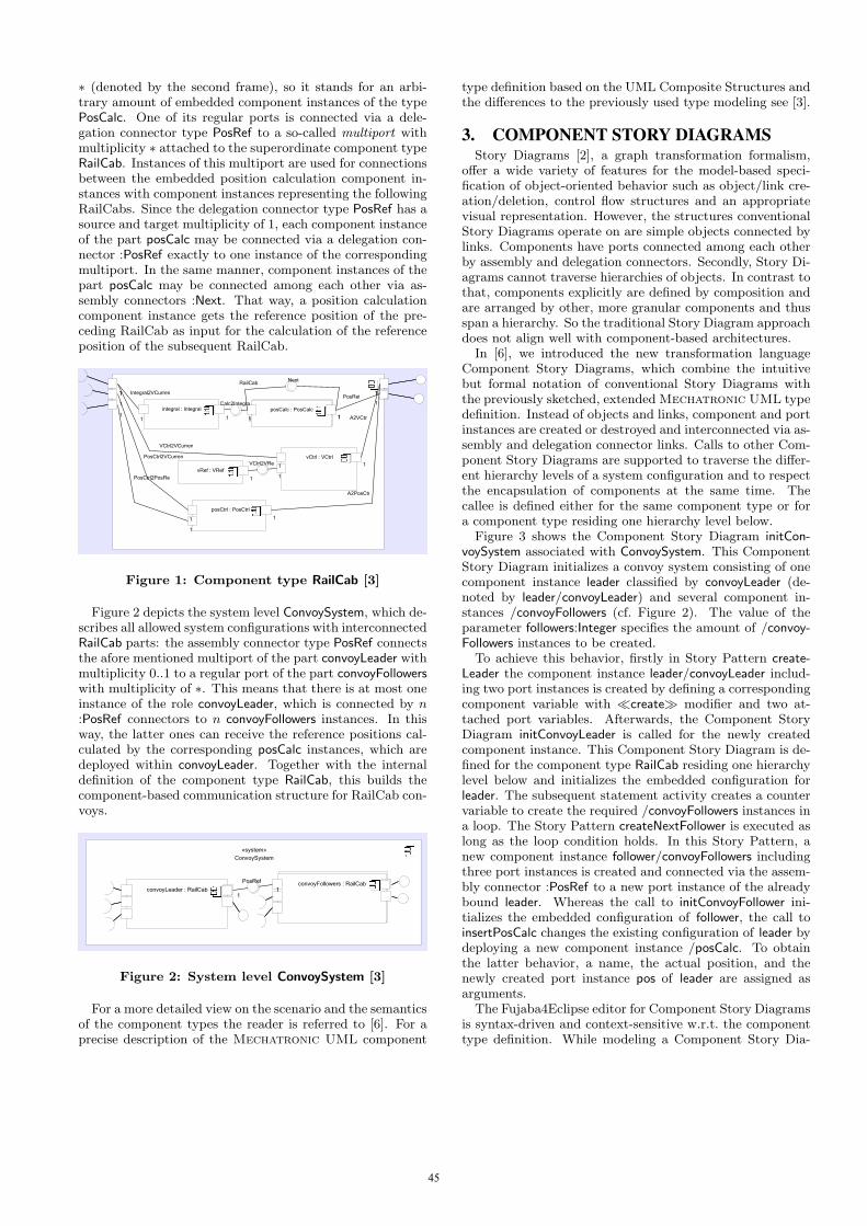
∗ (denoted by the second frame), so it stands for an arbi-trary amount of embedded component instances of the typePosCalc. One of its regular ports is connected via a dele-gation connector type PosRef to a so-called multiport withmultiplicity ∗ attached to the superordinate component typeRailCab. Instances of this multiport are used for connectionsbetween the embedded position calculation component in-stances with component instances representing the followingRailCabs. Since the delegation connector type PosRef has asource and target multiplicity of 1, each component instanceof the part posCalc may be connected via a delegation con-nector :PosRef exactly to one instance of the correspondingmultiport. In the same manner, component instances of thepart posCalc may be connected among each other via as-sembly connectors :Next. That way, a position calculationcomponent instance gets the reference position of the pre-ceding RailCab as input for the calculation of the referenceposition of the subsequent RailCab.
RailCab
vRef : VRef
posCalc : PosCalcintegral : Integral
posCtrl : PosCtrl
vCtrl : VCtrl
A2VCtrl
1
1
A2PosCtrl
1
1Integral2VCurrent1
1
VCtrl2VCurrent
1
1
PosCtrl2VCurrent
1
1
PosCtrl2PosRef
1
1
PosRef
1
1
1 1
VCtrl2VRef
11
Next
1 1
Calc2Integral
Figure 1: Component type RailCab [3]
Figure 2 depicts the system level ConvoySystem, which de-scribes all allowed system configurations with interconnectedRailCab parts: the assembly connector type PosRef connectsthe afore mentioned multiport of the part convoyLeader withmultiplicity 0..1 to a regular port of the part convoyFollowerswith multiplicity of ∗. This means that there is at most oneinstance of the role convoyLeader, which is connected by n:PosRef connectors to n convoyFollowers instances. In thisway, the latter ones can receive the reference positions cal-culated by the corresponding posCalc instances, which aredeployed within convoyLeader. Together with the internaldefinition of the component type RailCab, this builds thecomponent-based communication structure for RailCab con-voys.
convoyFollowers : RailCabconvoyLeader : RailCab
«system»
ConvoySystem
11
PosRef
Figure 2: System level ConvoySystem [3]
For a more detailed view on the scenario and the semanticsof the component types the reader is referred to [6]. For aprecise description of the Mechatronic UML component
type definition based on the UML Composite Structures andthe differences to the previously used type modeling see [3].
3. COMPONENT STORY DIAGRAMSStory Diagrams [2], a graph transformation formalism,
offer a wide variety of features for the model-based speci-fication of object-oriented behavior such as object/link cre-ation/deletion, control flow structures and an appropriatevisual representation. However, the structures conventionalStory Diagrams operate on are simple objects connected bylinks. Components have ports connected among each otherby assembly and delegation connectors. Secondly, Story Di-agrams cannot traverse hierarchies of objects. In contrast tothat, components explicitly are defined by composition andare arranged by other, more granular components and thusspan a hierarchy. So the traditional Story Diagram approachdoes not align well with component-based architectures.
In [6], we introduced the new transformation languageComponent Story Diagrams, which combine the intuitivebut formal notation of conventional Story Diagrams withthe previously sketched, extended Mechatronic UML typedefinition. Instead of objects and links, component and portinstances are created or destroyed and interconnected via as-sembly and delegation connector links. Calls to other Com-ponent Story Diagrams are supported to traverse the differ-ent hierarchy levels of a system configuration and to respectthe encapsulation of components at the same time. Thecallee is defined either for the same component type or fora component type residing one hierarchy level below.
Figure 3 shows the Component Story Diagram initCon-voySystem associated with ConvoySystem. This ComponentStory Diagram initializes a convoy system consisting of onecomponent instance leader classified by convoyLeader (de-noted by leader/convoyLeader) and several component in-stances /convoyFollowers (cf. Figure 2). The value of theparameter followers:Integer specifies the amount of /convoy-Followers instances to be created.
To achieve this behavior, firstly in Story Pattern create-Leader the component instance leader/convoyLeader includ-ing two port instances is created by defining a correspondingcomponent variable with �create� modifier and two at-tached port variables. Afterwards, the Component StoryDiagram initConvoyLeader is called for the newly createdcomponent instance. This Component Story Diagram is de-fined for the component type RailCab residing one hierarchylevel below and initializes the embedded configuration forleader. The subsequent statement activity creates a countervariable to create the required /convoyFollowers instances ina loop. The Story Pattern createNextFollower is executed aslong as the loop condition holds. In this Story Pattern, anew component instance follower/convoyFollowers includingthree port instances is created and connected via the assem-bly connector :PosRef to a new port instance of the alreadybound leader. Whereas the call to initConvoyFollower ini-tializes the embedded configuration of follower, the call toinsertPosCalc changes the existing configuration of leader bydeploying a new component instance /posCalc. To obtainthe latter behavior, a name, the actual position, and thenewly created port instance pos of leader are assigned asarguments.
The Fujaba4Eclipse editor for Component Story Diagramsis syntax-driven and context-sensitive w.r.t. the componenttype definition. While modeling a Component Story Dia-
45

createNextFollower
this
leader
insertPosCalc ( "posCalc" + i , i ,
pos )
«create»
follower / convoyFollowers : RailCab
initConvoyFollower ( )
int i = 1;
ConvoySystem::initConvoySystem( followers:Integer)
createLeader
this
«create»
leader / convoyLeader : RailCab
initConvoyLeader ( )
follower.setName("follower" + i); i++;
adadadad ConvoySystem::initConvoySystem()
:PosRef[i <= followers]
[else]
Figure 3: Component Story Diagram initConvoySystem [3]
gram for ConvoySystem, for example, as shown in Figure 3,the user can only assign parts to component variables whichare defined in ConvoySystem, namely convoyLeader and con-voyFollowers (cf. Figure 2). Both parts are interconnectedby the assembly connector type PosRef attached to certainport types. Thus, you can only assign this connector typeto the assembly link used in Story Pattern createNextFol-lower. Component variables can be associated with calls toComponent Story Diagrams; the callee is selected from theComponent Story Diagrams defined for the correspondingcomponent type RailCab of the variable’s part (cf. Table 1).Arguments representing a port variable, for example, haveto be selected from the set of possible variables w.r.t. the sig-nature of the callee. Further and in particular more complexComponent Story Diagrams can be found in [3].
4. CODE GENERATIONTo make use of existing code generation techniques, Com-
ponent Story Diagrams are translated to conventional StoryDiagrams based upon the Mechatronic UML metamodel.The translation is defined by TGG [5] rules, which thus de-scribe the formal semantics of Component Story Diagrams.Fujaba’s TGG plugins [7] are employed as concrete mod-eling and execution environment. A new code generationplugin takes the Mechatronic UML component type def-inition and Component Story Diagrams as input and trans-forms them using the translation rules to Story Diagramsclassified by the metamodel.
Figure 4 shows a part of the Story Diagram which is gener-ated from the Component Story Diagram of Figure 3.2 Thetranslation is for the most part straightforward. The controlflow is basically unchanged. All variables in a ComponentStory Pattern are translated to objects of classes of the meta-model; for example, the component variable this is translatedto the object parentComponentInstance:ComponentInstance.The variables’ stereotypes are translated accordingly. Note
2Actually, it is not a conventional Story Diagram but aslightly extended version which we chose due to implemen-tation issues. The only difference in this example is thetransformation call node. This node executes another StoryDiagram after all specified changes like creating and destroy-ing edges and nodes have been executed.
the special case of the leader component variable transla-tion. The translation honors the component type defini-tion of Figure 2 which specifies that a convoy may onlycontain one leader RailCab. Adopting conventional StoryPattern semantics, an additional optional object leaderCom-ponentInstanceToDelete is added to the generated Story Pat-tern which removes the old leader when a new one is created.Statement activities are taken over without modifications.
A more detailed view on the translation is sketched in [6],while the complete translation and an example of a trans-lated Story Diagram is given in [3].
Executable code is generated from the translated StoryDiagrams. Table 1 lists an overview of the used variablesand links in Component Story Diagrams (second column)as well as in the translated Story Diagrams (third column)and of the generated Lines of Code (last column) for allevaluated Component Story Diagrams. This overview indi-cates the reduction of complexity by using Component StoryDiagrams on Mechatronic UML component structures in-stead of modeling Story Diagrams based upon the Mecha-tronic UML metamodel. Note however that the generatedLOC are not only related to the actual amounts of variablesand links but to a greater extent to loops and iterations over∗-associations.
The generated code can be executed at design time oncomponent instance diagrams in Fujaba4Eclipse.
5. CONCLUSION AND FUTURE WORKThis paper introduced tool support for the modeling
and the execution of sophisticated structural reconfigura-tions for component-based architectures by presenting anextended Mechatronic UML component type definitionand a context-sensitive editor as well as a code generationplugin for Component Story Diagrams.
Currently there are two important open issues. First,Component Story Diagrams do not support negative or op-tional variables like conventional Story Diagrams. Sincethere are compositional dependencies between componentsand attached ports and between ports and linked connectors,the scope of a negative component variable, for example, in-cludes also compositionally dependent variables. These haveto be translated to a group of connected negative object vari-
46

InitConvoySystem( parentComponentInstance:ComponentInstance , followers:Integer)
createNextFollower
«create»posCurrent: DiscretePortInstance
convoySystem: Component
«create»posRefIn: DiscretePortInstance
aConvoyFollowersPortPart: PortPartleader componentInstanceDiagram: ComponentInstanceDiagram
parentComponentInstance
«create»follower: SoftwareComponentInstance
«create»pos: DiscretePortInstance
convoyLeaderComponentPart: ComponentPart
Transformation CallInsertPosCalc
posCalcName = "posCalc" + iposition = i
«create»aFollower: DiscretePortInstance
«create»followerInnerDiag: ComponentInstanceDiagram
convoyFollowersComponentPart: ComponentPart
Transformation CallInitConvoyFollower posConvoyLeaderPortPart: PortPart
posCurrentConvoyFollowersPortPart: PortPart
posRefConvoyFollowersPortPart: PortPart
«create»posRef: Assembly
posRefAssemblyType: AssemblyType
«create»posRef3_1RequiredInterfaceInstance: RequiredInterfaceInstance
«create»posRef2_1ProvidedInterfaceInstance: ProvidedInterfaceInstance
posRef2ProvidedInterfacePart: ProvidedInterfacePart
posRef3RequiredInterfacePart: RequiredInterfacePart
createLeader
componentInstanceDiagram: ComponentInstanceDiagram
«create»leaderInnerDiag: ComponentInstanceDiagram
convoyLeaderComponentPart: ComponentPart
name == "convoyLeader"
parentComponentInstance convoySystem: Component
«create»leader: SoftwareComponentInstance
name := "leader"
«destroy»leaderComponentInstanceToDelete: SoftwareComponentInstance
«create»vCurrent: DiscretePortInstance
name := "vCurrent"
«create»a: DiscretePortInstance
name := "a"
Transformation CallInitConvoyLeader
vCurrentConvoyLeaderPortPart: PortPart
name == "vCurrent"
aConvoyLeaderPortPart: PortPart
name == "a"
int i = 1;
follower.setName("follower" + i); i++;
Success
td InitConvoySystem
has
instances
containsisComposedOf
isComposedOfisComposedOfinstanceOfout
has
contains
hasinstances
instances
has
has
contains
«argument»parentComponentInstance
instancescontains
containscontains
contains
contains
contains
innerDiag
innerDiag
has
«argument»parentComponentInstance
instances
has
in
instances«argument»posParam
has
has
has
has
has
fromto
instances
provided
required
instances
instances
[i <= followers]
contains
contains
contains
contains
innerDiag
innerDiag
instances
has
instances
has
isComposedOf
instanceOf
has
has
«argument»parentComponentInstance
instances
instances
[else]
Figure 4: Excerpt of Story Diagram generated from Component Story Diagram initConvoySystem
Variables and Object variablesComp. Story Diag. connector links and links LOCConvoySystem::initConvoySystem 12 89 760ConvoySystem::insertFollower 8 69 605ConvoySystem::removeFollower 9 71 618RailCab::initConvoyFollower 11 89 695RailCab::initConvoyLeader 15 137 968RailCab::insertPosCalc 52 482 2806RailCab::removePosCalc 42 389 2422Overall 149 1326 8874
Table 1: Comparison of amounts of variables/links in Component Story Diagrams and in translated StoryDiagrams and of generated Lines of Code [3]
ables in the resulting translated Story Diagram. Until now,conventional Story Diagrams forbid such negative variablegroups, what also affects groups of optional variables. Aconcept has already been developed to solve this problem [3]but has not been implemented yet. Secondly, the presentedComponent Story Diagrams are selected and executed at de-sign time by an user. To obtain a self-adaptive approach formechatronic real-time systems, we are currently working onan integration of Component Story Diagrams into real-timestatecharts.
Future works could include extensions like attributes aswell as an inheritance concept for component types to pro-vide Component Story Diagrams with attribute conditionsand the matching of instances of derived component types.
6. REFERENCES[1] S. Burmester, H. Giese, and M. Tichy. Model-Driven
Development of Reconfigurable Mechatronic Systemswith Mechatronic UML. In U. Assmann, A. Rensink,and M. Aksit, editors, Model Driven Architecture:Foundations and Applications, volume 3599 of LectureNotes in Computer Science, pages 47–61. SpringerVerlag, Aug. 2005.
[2] T. Fischer, J. Niere, L. Torunski, and A. Zundorf. StoryDiagrams: A new Graph Rewrite Language based onthe Unified Modeling Language. In G. Engels and
G.Rozenberg, editors, Proc. of the 6th InternationalWorkshop on Theory and Application of GraphTransformation (TAGT), Paderborn, Germany, LNCS1764. Springer Verlag, 1998.
[3] J. Holtmann. Graphtransformationen furkomponentenbasierte Softwarearchitekturen. Master’sthesis, University of Paderborn, Germany, April 2008.
[4] Object Management Group. UML 2.0 SuperstructureSpecification, October 2004. Document: ptc/04-10-02(convenience document).
[5] A. Schurr. Specification of Graph Translators withTriple Graph Grammars. In Proc. of the 20th
International Workshop on Graph-Theoretic Conceptsin Computer Science, Herrschin, Germany, June 1994.Spinger Verlag.
[6] M. Tichy, S. Henkler, J. Holtmann, and S. Oberthur.Component Story Diagrams: A TransformationLanguage for Component Structures. In Postproc. ofthe 4th Workshop on Object-oriented Modeling ofEmbedded Real-Time Systems (OMER 4), Paderborn,Germany, 2008.
[7] R. Wagner. Developing Model Transformations withFujaba. In H. Giese and B. Westfechtel, editors, Proc.of the 4th International Fujaba Days 2006, Bayreuth,Germany, volume tr-ri-06-275 of Technical Report,pages 79–82. University of Paderborn, September 2006.
47
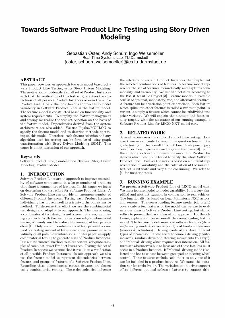
Towards Software Product Line Testing using Story DrivenModeling
Sebastian Oster, Andy Schürr, Ingo WeisemöllerReal-Time Systems Lab, TU Darmstadt
{oster, schuerr, weisemoeller}@es.tu-darmstadt.de
ABSTRACTThis paper provides an approach towards model based Soft-ware Product Line Testing using Story Driven Modeling.The motivation is to identify a small set of Product Instancessuch that the verification of this test set guarantees the cor-rectness of all possible Product Instances or even the wholeProduct Line. One of the most famous approaches to modelvariability in Software Product Lines is the feature model.The feature model is constructed based on functionality andsystem requirements. To simplify the feature managementand testing we realize the test set selection on the basis ofthe feature model. Dependencies derived from the systemarchitecture are also added. We use Fujaba/MOFLON tospecify the feature model and to describe methods operat-ing on this model. Therefore, each feature selection and anyalgorithm used for testing can be formulated using graphtransformation with Story Driven Modeling (SDM). Thispaper is a first discussion of our approach.
KeywordsSoftware Product Line, Combinatorial Testing , Story DrivenModeling, Feature Model
1. INTRODUCTIONSoftware Product Lines are an approach to improve reusabil-ity of software components in a large number of productsthat share a common set of features. In this paper we focuson decreasing the test effort for Software Product Lines. ASoftware Product Line can provide an enormous number ofdifferent Product Instances. Testing each Product Instanceindividually has proven itself as a trustworthy but extensivemethod. To decrease this effort we use the combinatorialtest design and adapt it to our approach. The idea of usinga combinatorial test design is not a new but a very promis-ing approach. With the best of our knowledge combinatorialtesting is mainly used to reduce the amount of test param-eters [1]. Only certain combinations of test parameters areused for testing instead of testing each test parameter indi-vidually or all possible combinations. In this paper we applycombinatorial testing to generate a set of Product Instances.It is a mathematical method to select certain, adequate sam-ples of combinations of Product Instances. Testing this set ofProduct Instances we assume that it results in a verificationof all possible Product Instances. In our approach we alsouse the feature model to represent dependencies betweenfeatures and groups of features of a Software Product Line.Regarding these dependencies, certain features are chosenusing combinatorial testing. These dependencies influence
the selection of certain Product Instances that implementthe selected combinations of features. A feature model rep-resents the set of features hierarchically and captures com-monality and variability. We use the notation according tothe BMBF feasiPLe Project [3]. Feature models in feasiPLeconsist of optional, mandatory, xor, and alternative features.A feature can be a variation point or a variant. Each featurewhich splits into other features is called a variation point. Avariant is simply a feature which cannot be subdivided intoother variants. We will explain the notation and function-ality roughly with the assistance of our running example aSoftware Product Line for LEGO NXT model cars.
2. RELATED WORKSeveral papers cover the subject Product Line testing. How-ever these work mainly focuses on the question how to inte-grate testing in the overall Product Line development pro-cess [6] or, how to generate and organize test cases [4]. In [5]the author also tries to minimize the amount of Product In-stances which need to be tested to verify the whole SoftwareProduct Line. However the work is based on a different rep-resentation of variability and the calculation of the minimaltest set is intricate and very time consuming. We refer to[5] for further details.
3. RUNNING EXAMPLEWe present a Software Product Line of LEGO model cars.We use a feature model to model variability. It is a very sim-plified and abstract example in comparison to real vehicles.The functionality is based on Lego Mindstorm NXT actors,and sensors. The corresponding feature model (cf. Fig.1)covers only a few features of the model car we use to eval-uate our ideas in Software Product Line testing, but shouldsuffice to present the basic ideas of our approach. For the fol-lowing explanation please consult the corresponding featuremodel. The feature model consists of software features (driv-ing/steering mode & driver support) and hardware features(sensors & actuators). Driving mode offers three differenttypes of locomotion. These are autonomous driving (”Auto-motive”), random drive and steering movements (”Crazy”),and ”Manual”driving which requires user interacion. All fea-tures are alternatives but at least one of these features mustoccur in a Product Instance. If ”Manual” driving mode is se-lected one has to choose between gamepad or steering wheelcontrol. These features exclude each other so only one of itcan be included in a product instance. We name this nota-tion xor for exclusive-or. The variation point driver supportoffers different optional software features to support driv-
48
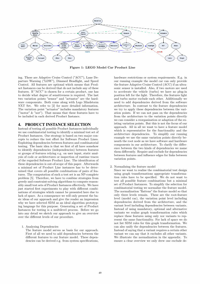
Figure 1: LEGO Model Car Product Line
ing. These are Adaptive Cruise Control (”ACC”), Lane De-parture Warning (”LDW”), Dimmed Headlight, and SpeedControl. All features are optional which means that Prod-uct Instances can be derived that do not include any of thesefeatures. If ”ACC” is chosen for a certain product, one hasto decide what degree of sensitiveness is required. The lasttwo variation points ”sensor” and ”actuator” are the hard-ware components. Both come along with Lego MindstormNXT Set. We refer to [2] for more detailed information.The variation point ”actuator” includes mandatory features(”motor” & ”nxt”). That means that these features have tobe included in each derived Product Instance.
4. PRODUCT INSTANCE SELECTIONInstead of testing all possible Product Instances individuallywe use combinatorial testing to identify a minimal test set ofProduct Instances. Our strategy is based on two major con-cepts to reduce the test effort for Software Product Lines.Exploiting dependencies between features and combinatorialtesting. The basic idea is that we first of all have somehowto identify dependencies (independencies) between featuresor groups of features relying e.g. on user input, static anal-ysis of code or architectures or inspection of runtime tracesof the regarded Software Product Line. The identificaton ofthese dependencies is out-of-scope of this paper. Afterwardsa minimal set of Product Line instances has to be deter-mined that covers all possible combinations of pairs of fea-tures. The computation of such a test set is an NP-completeproblem [5]. Therefore, we have to combine strategies fromgreedy and constraint-solving algorithms to compute reason-ably small test sets of Product Instances effectively. We havejust started first experiments to play with different combi-nations of strategies which cannot be presented here due tolack of space. As a consequence we will only present the ba-sic ideas of our approach and give the reader an impressionwhy we have selected SDM as an ideal algorithm prototyp-ing language for this purpose. Generating a set of ProductInstances for testing is a multilevel process. Before we gointo any detail we sketch our approach to give an overviewover the different levels of our procedure.
1. Analysing DependenciesThe feature model serves as basis for our approach.First of all we need to add dependencies between thedifferent features to our feature model. These depen-dencies can be derived e.g. from system specifications,
hardware restrictions or system requirements. E.g. inour running example the model car can only providethe feature Adaptive Cruise Control (ACC) if an ultra-sonic sensor is installed. Also, if two motors are usedto accelerate the vehicle (turbo) we have no plug-inposition left for the light. Therefore, the features lightand turbo motor exclude each other. Additionally weneed to add dependencies derived from the softwarearchitecture. In contrast to the feature dependencieswe try to apply these dependencies between the vari-ation points. If we can not pass on the dependenciesfrom the architecture to the variation points directlywe can consider a reorganisation or adaption of the ex-isting variation points. But this is not the focus of ourapproach. All in all we want to have a feature modelwhich is representative for the functionality and thearchitecture dependencies. To simplify our runningexample we use the same variation points directly be-neath the root node as we have software and hardwarecomponents in our architecture. To clarify the differ-ence between the two kinds of dependencies we namethem differently. Require and exclude for dependenciesbetween features and influence edges for links betweenvariation points.
2. Normalizing the feature modelSince we want to realize the combinatorial test designusing graph transformations appropriate transforma-tion rules have to be specified. We do not want totest all possible feature combinations but a minimalset of Product Instances. To simplify the selection forcombinatorial testing we normalize the feature model.The normalization ”flattens” the feature model so thatonly three levels remain. These are the root-featurelevel (model car), the variation point level includingdependencies derived from the architecture, and thevariant level including dependencies between variants.Instead of using mandatory, optional and alternativevariants we realize graph transformation rules whichreplace these features using only xor variants to rep-resent the same functionality. For lack of space we donot list SDM rules for this graph transformation. Wecan also unify the dependencies between the features.Instead of saying that a variant requires a certain othervariant we can say that it excludes all other variants.We illustrate the normalization in the appendix. Toensure a clear overview we only drew one exclude de-
49
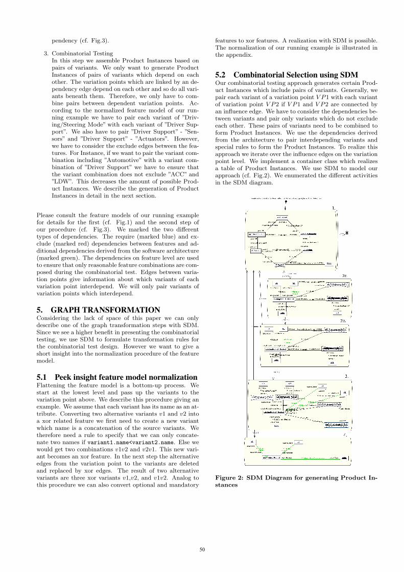
pendency (cf. Fig.3).
3. Combinatorial TestingIn this step we assemble Product Instances based onpairs of variants. We only want to generate ProductInstances of pairs of variants which depend on eachother. The variation points which are linked by an de-pendency edge depend on each other and so do all vari-ants beneath them. Therefore, we only have to com-bine pairs between dependent variation points. Ac-cording to the normalized feature model of our run-ning example we have to pair each variant of ”Driv-ing/Steering Mode” with each variant of ”Driver Sup-port”. We also have to pair ”Driver Support” - ”Sen-sors” and ”Driver Support” - ”Actuators”. However,we have to consider the exclude edges between the fea-tures. For Instance, if we want to pair the variant com-bination including ”Automotive” with a variant com-bination of ”Driver Support” we have to ensure thatthe variant combination does not exclude ”ACC” and”LDW”. This decreases the amount of possible Prod-uct Instances. We describe the generation of ProductInstances in detail in the next section.
Please consult the feature models of our running examplefor details for the first (cf. Fig.1) and the second step ofour procedure (cf. Fig.3). We marked the two differenttypes of dependencies. The require (marked blue) and ex-clude (marked red) dependencies between features and ad-ditional dependencies derived from the software architecture(marked green). The dependencies on feature level are usedto ensure that only reasonable feature combinations are com-posed during the combinatorial test. Edges between varia-tion points give information about which variants of eachvariation point interdepend. We will only pair variants ofvariation points which interdepend.
5. GRAPH TRANSFORMATIONConsidering the lack of space of this paper we can onlydescribe one of the graph transformation steps with SDM.Since we see a higher benefit in presenting the combinatorialtesting, we use SDM to formulate transformation rules forthe combinatorial test design. However we want to give ashort insight into the normalization procedure of the featuremodel.
5.1 Peek insight feature model normalizationFlattening the feature model is a bottom-up process. Westart at the lowest level and pass up the variants to thevariation point above. We describe this procedure giving anexample. We assume that each variant has its name as an at-tribute. Converting two alternative variants v1 and v2 intoa xor related feature we first need to create a new variantwhich name is a concatenation of the source variants. Wetherefore need a rule to specify that we can only concate-nate two names if variant1.name<variant2.name. Else wewould get two combinations v1v2 and v2v1. This new vari-ant becomes an xor feature. In the next step the alternativeedges from the variation point to the variants are deletedand replaced by xor edges. The result of two alternativevariants are three xor variants v1,v2, and v1v2. Analog tothis procedure we can also convert optional and mandatory
features to xor features. A realization with SDM is possible.The normalization of our running example is illustrated inthe appendix.
5.2 Combinatorial Selection using SDMOur combinatorial testing approach generates certain Prod-uct Instances which include pairs of variants. Generally, wepair each variant of a variation point V P1 with each variantof variation point V P2 if V P1 and V P2 are connected byan influence edge. We have to consider the dependencies be-tween variants and pair only variants which do not excludeeach other. These pairs of variants need to be combined toform Product Instances. We use the dependencies derivedfrom the architecture to pair interdepending variants andspecial rules to form the Product Instances. To realize thisapproach we iterate over the influence edges on the variationpoint level. We implement a container class which realizesa table of Product Instances. We use SDM to model ourapproach (cf. Fig.2). We enumerated the different activitiesin the SDM diagram.
Figure 2: SDM Diagram for generating Product In-stances
50

In the first activity, all pairs of variants which influence eachother are determined. Variants influence each other if they1. do not exclude each other and 2. belong to two variationpoints which are linked by a dependency edge. If this pairof variants is not covered by an existing product instancewe apply the following rules to try to extend an existingproduct instance.
1. We check if an existing Product Instance already cov-ers one of those variants and if the variation point ofthe other variant is still unbound. We can then useactivity 2a or 2b to add the mentioned variant to anexisting Product Instance.
2. If the rule above fails the third activity will look for aproduct instance in which the two concerning variationpoints of the variants are still unbound.
If no Product Instance can be found which can be extendedwe have to create a new Product Instance.
6. CONCLUSIONWe can use SDM to select certain Product Instances fortesting and for the normalization of the feature model. Thisis our first approach using graph transformation on featuremodels to realize combinatorial testing for Software Prod-uct Lines. We have to examine different and very complexalgorithms which can operate on graphical structurs. Fu-jaba/MOFLON is an ideal tool for high-level specificationand the rapid prototyping of these algorithms. Since the cal-culation of a minimal test set is a NP-complete optimizationproblem we can not guarantee that our test set of ProductInstances is minimal. However we decreased the amount ofProduct Instances which need to be tested dramatically incomparison to testing all Product Instances.
7. REFERENCES[1] D. M. Cohen, S. R. Dalal, A. Kajla, and G. Patton.
The automatic efficient tests generator. Fifth Int’lSymposium on Software Reliability Engineering,IEEE:303–309, 1994.
[2] LEGO. www.lego.com.
[3] F. P. Page. www.feasiple.de.
[4] K. Pohl and A. Metzger. Software product line testing.Communications of ACM, 49(12), 2006.
[5] K. Scheidemann. Verifying families of systemconfigurations. Doctoral Thesis, TU Munich, 2007.
[6] A. Tevanlinna, J. Taina, and R. Kauppinen. Productfamily testing: a survey. ACM SIGSOFT SoftwareEngineering Notes., 29, 2004.
APPENDIXA. NORMAILZED FEATURE MODEL
Figure 3: Normalized Feature Model
51

Integration of Legacy Components inMechatronicUML Architectures∗
Christian Brenner, Stefan Henkler,Martin Hirsch, and Claudia Priesterjahn
Software Engineering GroupUniversity of Paderborn
Warburger Str. 100D-33098 Paderborn, Germany
[cbr|shenkler|mahirsch|cpr]@uni-paderborn.de
Holger GieseSystem Analysis and Modeling Group
Hasso Plattner InsituteUniversity of Potsdam
Prof.-Dr.-Helmert-Str. 2-3D-14482 Potsdam, Germany
ABSTRACTOne of the main benefits of the component-based develop-ment paradigm is its support for reuse which is guided by theinterface description of the components. This facilitates theconstruction of complex functionality by the flexible compo-sition of components. However, the also required verificationof the resulting system often becomes intractable in practiceas no abstract model of the reused components, which canserve the verification purpose, is available for the integratedlegacy components. In this paper, we present the integrationof legacy components in a Mechatronic UML model by anincremental synthesis of the communication behavior of theembedded legacy components combined with compositionalverification.
1. INTRODUCTIONOne of the main benefits of the component-based develop-ment paradigm is its support for reuse which is guided bythe interface description of the components (cf. [10, 2]). Ingeneral, the proper composition of independent developedcomponents in the software architecture of embedded real-time systems requires means for a sufficient verification ofthe integration step either by testing or formal verification.However, the overwhelming complexity of the interaction ofdistributed real-time components usually excludes that test-ing alone can provide the required coverage when integratinglegacy components.
Thus formal verification techniques seem to be a valuablealternative. However, the required verification of the result-ing system often becomes intractable as no abstract modelof the reused components which can serve the verificationpurpose is available for legacy components.
A number of techniques which either use a black-box ap-proach and automata learning [8] or a white-box approachwhich extracts the models from the code [9, 1, 7] exists.However, these approaches did not consider the specific con-text for efficiently synthesizing the relevant behavior of thelegacy component, which is of paramount importance forembedded systems. Further, these approaches are not capa-
∗This work was partly developed in the course of the Spe-cial Research Initiative 614 – Self-optimizing Concepts andStructures in Mechanical Engineering – University of Pader-born, and was published on its behalf and funded by theDeutsche Forschungsgemeinschaft.
ble of finding conflicts in early learning steps.In this paper we present a tool support for the incre-
mental synthesis of communication behavior for embeddedlegacy components by combining compositional verificationand model-based testing techniques based on [4, 6]. For theexploration of the component’s behavior a formal model ofthe component’s environment is applied. The environmentmodel is employed to derive known environment behaviorwhich is then used to systematically synthesize the relevantbehavior of the legacy component as well as a formal modeldescribing its communication behavior. While this formalmodel is not a valid encoding of all possible behavior of thelegacy component, it is in fact a valid representation of itscommunication behavior for the context relevant for its em-bedding.
In the next section we present the incremental synthesisapproach. Afterwards we describe the implementation aswell as the evaluation. We finish the paper with the conclu-sion and future work.
2. INTEGRATION OFLEGACY COMPONENTS
Given a concrete context and a concrete component imple-mentation with hidden internal details (legacy component),the basic question we want to check is whether a given prop-erty φ as well as deadlock freedom (¬δ) holds. We are in par-ticular interested in a guarantee that both properties holdor a counterexample witnessing that they do not hold. How-ever, usually the legacy component cannot be employed totraverse the whole state space as the state space of the com-plete system is too large to directly address this question.Before we answer the question, we discuss in the next sec-tion the prerequisites our approach. Afterward, we presentan overview of our approach and discuss in more detail therelevant technique in Section 2.3.
2.1 PrerequisitesThe approach presented in this paper will only work, if cer-tain prerequisites and constraints can be fulfilled by thelegacy component. The component must have neither non-deterministic nor pseudo-nondeterministic behavior. For ex-ample the firing of transitions must not directly depend onvariable values or timing constraints since they are currentlynot explicitly captured. Such conditions will only be valid,
52

if they are encapsulated in the state information. All tran-sitions must fire within a given timespan after the receiptof a triggering message. That is to prevent that a test runwhich leads to a deadlock will not terminate. This times-pan also applies to ε-transitions. In this case the timespanstarts at the entry to the transition’s start state. To enablethe learning of the behavior the definitions of the compo-nent’s interfaces muss be known, a start state must be givenand it must be possible to reset to this start state. Further,the state changes (current state) must be observable at theinterface.
Our experiences showed us that the prerequisites, besidesthe state information, are realistic for mechatronic systems,as this are reactive systems. As discussed in the future workwe have to extend our black-box approach with additionalwhite-box information, to abandon on the state informationat the interface of the legacy component.
2.2 Sketch of the Proposed ApproachGiven a Mechatronic UML architecture which embeds alegacy component and behavioral models for all other com-ponents building the context of the legacy component, thebasic question of correct legacy component integration iswhether for the composition of the legacy component andits context all anomalies such as deadlocks are excluded orall additionally required properties hold. However, it is usu-ally very expensive and risky to reverse-engineer an abstractmodel of the legacy component to verify whether the inte-gration will work.
To overcome this problem we suggest employing somelearning strategy via testing to derive a series of more de-tailed abstract models for the legacy component. The spe-cific feature of our approach will be that we exploit thepresent abstract model of the context to only test relevantparts of the legacy component behavior. The approach de-pends only to a minimal extent on reverse engineering re-sults.
We start with synthesizing a model of the legacy compo-nent behavior based on known structural interface descrip-tion. As shown in [4] we use a safe over approximation.Then, we check whether the context plus the model of legacybehavior exhibit any undesired behavior taking generic cor-rectness criteria or additional required properties into ac-count. If not, we use the resulting counterexample trace totest the legacy component. If the trace can be realized withthe legacy component, a real error has been found. If not,we first enrich the trace with additional information usingdeterministic replay [3] and then merge the enriched traceinto the model of the legacy component behavior. We re-peat the checks until either a real error has been found orall relevant cases have been covered.
Execute legacy
component
Produce
output
Synthesize
behavior
Extract behavioral
model of context
1
(Input vector)
Counterxample
[Counterexample confirmed]
[Properties satisfied]
Observed behavior
2
3
4
Check combination
Mlegacy Mcontext
Mcontext Mlegacy
Figure 1: Sketch of the approach
Figure 1 illustrates our process with a summary of the over-all approach. 1) Initially, we synthesize an initial behaviormodel for the legacy component based on known structuralinterface description and derive a behavioral model of thecontext from the existing Mechatronic UML models. 2)We check the combination of the two behavioral models andeither get a) a counterexample or b) the checked propertiesare guaranteed. In the latter case we are done. 3) If we havea counterexample, we use this as test input for the legacycomponent. Deterministic replay enables us to enrich theobservable behavior with state information by monitoring.If the tested faulty run is confirmed, we have found a realcounterexample. If not, we can use the new observed be-havior to refine the previously employed behavior model ofthe legacy component. We repeat steps 2) to 4) until one ofthe described exits occurs.
The approach can be extended to multiple legacy com-ponents, by using the parallel combination of multiple be-havioral models. The iterative synthesis will then improveall these models in parallel. While theoretically possible, wecan currently provide no experience whether such a parallellearning is beneficial and useful for multiple legacy compo-nents. Our expectation that it depends on the degree inwhich the known context restricts their interaction whichdetermines which benefits our approach may show also forthis more advanced integration problems.
2.3 Chaotic ClosureFor our approach it is necessary that the model checkertakes into account every behavior which is possible accord-ing to our current knowledge about the system. To ac-complish this, the already known parts of the system areextended with chaotic behavior, resulting in a new modelcalled chaotic closure. The latter is then, in combinationwith a model of the context, subject to model checking.Namely, for all so far unknown behavior it is assumed thaton the one hand any possible interaction may occur but onthe other hand a deadlock is possible at any time as well.Therefore, the chaotic closure is an over approximation ofthe real system: It always models at least all of the sys-tem’s behavior, but not all of the modeled behavior has tobe possible in the system.
For modeling chaotic behavior a chaotic automaton, anon-deterministic finite automaton consisting of two states,can be used: The state sδ with no outgoing transitions rep-resents the case of the system being in a deadlock, neitherreceiving nor sending any messages. The state s∀ on thecontrary represents the case where all inputs being possiblefor the system are enabled and all outputs can occur. Thisis modeled by one self-transition and one transition to sδ
for each possible input (with no output) and each possibleoutput (with no input). For creating these transitions theinput- and output-alphabets of the system must be known.Both states of the chaotic automaton are initial states.
The chaotic closure is a combination of the synthesizedmodel with the chaotic automaton for the system, mappingall unknown behavior to a chaotic one. Figure 2 shows asan example the Chaotic Closures (on the right side) for atrivial first conjectured behavior model and for a slightlymore advanced one.
A Chaotic Closure is constructed as follows: First, thechaotic automaton for the input- and output-alphabets of
53

Figure 2: Example for a chaotic closure
the system is constructed. Then the states and transitionsof the chaotic automaton are added to the incomplete au-tomaton modeling the behavior that has been learned untilnow. For every combination of a state and an incoming oroutgoing event for which a transition neither has been de-fined nor excluded, a new transition is created from thatstate to both the s∀ and the sδ state. Contrary to the syn-thesized behavior, the chaotic closure constructed for it isnon-deterministic.
The explicit deadlock state sδ in the chaotic hull makessure that as long as there still is behavior left to learn, themodel checker will be able to find a deadlock. The resultis that in every iteration of our approach at least one newtransition is learned. However this only applies to behaviorof the system which can be reached in combination with themodel of the context. Any other behavior is not consideredto be relevant in the context the system is integrated into,and therefore no time needs to be wasted with testing it.
3. IMPLEMENTATION AND EVALUA-TION
As the aim of our synthesis approach is to allow tosafely integrate legacy components into existing Mecha-tronic UML contexts, it has been implemented in a waythat it is on the one hand compatible to models created withthe Fujaba Real-Time Tool Suite and on the other hand doesnot rely on a specific testing framework. The latter is im-portant because it depends on the legacy component, whichtesting framework can be used. To accomplish this, the be-havior synthesis step, being the core of the approach, wasimplemented in Java as a command-line tool. For the ver-ification step, the model checker verifyta of the integratedtool environment UPPAAL has been chosen.
In the synthesis tool automata are saved as Extended Hi-erarchical Timed Automata (ExHTA), which have the samesemantics as Fujaba Real-Time Statecharts (RTSCs), in atool-independent XML-format. This has several advantages:As RTSCs can be exported into this format, it is possibleto use a context which has been modeled in Fujaba usingMechatronic UML. Also the Uppaal Plugin provides away to convert ExHTA to Timed Automata which can be
validated using verifyta. It is possible to enable support forother model checkers as well, by implementing additionalmappings to the formats they are using. Finally, the modelsynthesized by our approach also is saved in ExHTA. Thisshould simplify implementing a method for loading it as aRTSC in Fujaba1.
The first execution of the synthesis tool creates thefirst trivial behavior model, it constructs the correspond-ing chaotic closure by using the system’s i/o-interface and itcombines it with the model of the context. The subsequentexecution of the (slightly modified) Uppaal Plugin convertsthis combination from ExHTA to the Uppaal XML-format.Then verifyta is used for model checking it against the prop-erties defined in a certain CTL dialect. The resulting coun-terexample (if any) is then used on the one hand by a testingframework to execute it as a test case, on the other handit is used by the synthesis tool for comparing it against thetrace resulting from those tests. If trace and counterexam-ple conform, a message will be issued by the tool. Otherwisethe trace is used for learning new behavior (and so on).
Shuttle 1 Shuttle 2
DistanceCoordinationcontext
(Fujaba)
legacy component(MATLAB/Simulink)
frontRole rearRole
Figure 3: Component diagram for the scenario usedfor evaluation of our approach
Using the synthesis tool, our approach has been evalu-ated within a MATLAB simulation for the case of a MAT-LAB/Simulink legacy component being integrated into anexisting Mechatronic UML system model. Figure 3 showsa component diagram picturing the scenario considered forthis. The components in this diagram are two Rail CabShuttles, safety critical mechatronic systems, communicat-ing with each other within a collaboration pattern. One ofthese Shuttles, the one that made the decisions, was the con-text in our approach. The other one, which was a reactivesystem, was the system to be integrated.
To realize the evaluation, a simple testing framework wasimplemented within MATLAB/Simulink. The main task ofthis framework is the execution of the counterexamples pro-vided by the model checker as test cases: It sends a messageto the system whenever the context would send one accord-ing to the counterexample and it logs all communication andall state changes of the system. Additionally, by calling thesynthesis tool and the model checker it is able to executeour approach automatically for this scenario.
The evaluation showed that our approach is able to suc-cessfully synthesize a correct model for the given scenario.Also a simple error that had been added to the simulationcould be found. However, it turned out that the synthesisneeded quite a few steps, especially for learning the completecorrect model. This was due to the model checker return-ing only very short counterexamples which lead to only onetransition being learned in each iteration of the approach.
1An implementation for this is currently under development.
54
The total amount of testing necessary was greatly increasedby this because to reach a new transition, often much of thealready known behavior had to be tested again.
A way to force the model checker to create longer coun-terexamples is instrumenting the Chaotic Closure and mod-ifying the temporal logic formula used by the model checker.These changes can be used together with certain commandline options to make verifyta try to maximize the numberof some transitions in the counterexamples. Three differentmodifications of this kind have been tried: One possibilityis to increase the number of self-transitions of s∀ up to amaximum value. However this has the drawback that ver-ifyta usually uses several iterations of one loop to achievethis. Another option is to make the model checker try touse every self-transition of s∀ at least once in each coun-terexample. Finally, the model checker can also be drivento try to let every counterexample contain every transitionof the context’s model. Each of these possibilities has beentested for our evaluation scenario, in several cases resultingin a much smaller amount of iterations and a smaller to-tal amount of testing steps as well. However the success ofeach of these modifications is likely to depend heavily on thespecific scenario they are used in.
In addition to the evaluation with MATLAB/Simulink wealso consider using our approach with the IPANEMA frame-work. Using our synthesis approach within this frameworkwould have the advantage of being able to use the model ofthe context on the one hand for exporting it to ExHTA andon the other hand for automatically generating code from itwhich can be compiled to run on the framework. A testingframework for model based testing [5] already exists whichcan be adapted to work in conjunction with the synthesistool. Also a Test Case Generator exists which can be usedfor converting counterexamples to test cases.
4. CONCLUSION AND FUTURE WORKIn this paper we have presented a tool support for the incre-mental synthesis of communication behavior for embeddedlegacy components by combining compositional verificationtechniques and model based testing. It enables context spe-cific learning with conflict detection in early learning steps.The employed learning strategy provides options for opti-mization as shown in the evaluation. The interplay betweenthe formal verification and the test could be improved whena number of counterexamples instead only single one couldbe derived from the model checker. This is achieved by usingspecific strategies of the model checker to derive counterex-amples.
Next, we want to combine the presented dynamic analy-sis with a static analysis to extend the applicability of theapproach. E.g., the parts of the code which are responsiblefor the current state or internal variable values and depen-dencies could be detected by a static analysis and used bythe dynamic analysis.
5. REFERENCES[1] J. C. Corbett, M. B. Dwyer, J. Hatcliff, S. Laubach,
C. S. Pasareanu, Robby, and H. Zheng. Bandera:extracting finite-state models from java source code.In International Conference on Software Engineering,pages 439–448, 2000.
[2] I. Crnkovic. Building Reliable Component-Based
Software Systems. Artech House, Inc., Norwood, MA,USA, 2002.
[3] H. Giese and S. Henkler. Architecture-driven platformindependent deterministic replay for distributed hardreal-time systems. In Proceedings of the 2ndInternational Workshop on The Role of SoftwareArchitecture for Testing and Analysis(ROSATEA2006), pages 28–38, New York, NY, USA,July 2006. ACM Press.
[4] H. Giese, S. Henkler, and M. Hirsch. CombiningCompositional Formal Verification and Testing forCorrect Legacy Component Integration inMechatronic UML. In R. de Lemos, F. D.Giandomenico, C. Gacek, H. Muccini, and M. Vieira,editors, Architecting Dependable Systems V, volume5135 of LNCS, pages 248–272. SPRINGER, 2008.
[5] H. Giese, S. Henkler, M. Hirsch, and C. Priesterjahn.Model-based testing of mechatronic systems. InL. Geiger, H. Giese, and A. Zundorf, editors, Proc. ofthe 5th International Fujaba Days 2007, Kassel,Germany, pages 1–4, September 2007.
[6] S. Henkler and M. Hirsch. Compositional validation ofdistributed real time systems. In OMER4 -Object-oriented Modeling of Embedded Real-TimeSystems, pages 1–6, 2007. accepted.
[7] G. J. Holzmann and M. H. Smith. A practical methodfor verifying event-driven software. In ICSE ’99:Proceedings of the 21st international conference onSoftware engineering, pages 597–607, Los Alamitos,CA, USA, 1999. IEEE Computer Society Press.
[8] H. Hungar, O. Niese, and B. Steffen. Domain-specificoptimization in automata learning. In In Proc. 15 Int.Conf. on Computer Aided Verification, 2003.
[9] D. Lucio, J. Kramer, and S. Uchitel. Model extractionbased on context information. In ACM/IEEE 9thInternational Conference on Model DrivenEngineering Languages and Systems, LNCS. Springer,2006.
[10] C. Szyperski. Component Software and the WayAhead. In G. T. Leavens and M. Sitaraman, editors,Foundations of Component-Based Systems,incollection 1, pages 1–20. Cambridge UniversityPress, New York, NY, 2000.
55