Embed Size (px)
Citation preview
Falcon 35 MKII FM, ST/WEB, TV
Digital Audio Processor
User Manual (Rev. 3.5)
Sede BOLOGNA: Via Caduti Di Sabbiuno 6/F – 40011 Anzola Emilia - Bologna - Italy
Tel. +39 051 736555 - Fax. +39 051 736170
Sede BERGAMO: Via Italia 1 – 24030 Medolago (Bg) – Italy
e-mail: [email protected] - web site: www.axeltechnology.com

This manual is for use with the following product : Falcon 35 FM, ST/WEB, TV Axel Technology SRL All Rights Reserved Via Caduti Di Sabbiuno 6/F - 40011 Anzola Emilia - Bologna - Italy Tel. +39 051 736555 – + 39 051 736154 Fax. +39 051 736170 e-mail: [email protected] - web site: www.axeltechnology.com Information in this document is subject to change without notice and does not represent a commitment on the part of the vendor. This manual images could differ a bit from the equipment actual design. Axel Technology SRL shall not be liable for any loss or damage whatsoever arising from the use of information or any error contained in this manual. No part of this manual may be reproduced or transmitted in any form or by any means, electronic or mechanical, including photocopying, recording, information storage and retrieval systems, for any purpose other than the purchaser’s personal use, without the express written permission of Axel Technology SRL.
TABLE OF CONTENTS
Page 3
1 TABLE OF CONTENTS 1 TABLE OF CONTENTS ............................................................................................................................. 3 2 AVAILABLE VERSIONS............................................................................................................................ 5
2.1 FM VERSION........................................................................................................................................................ 5 2.2 ST / WEB VERSION ............................................................................................................................................. 6 2.3 TV VERSION ........................................................................................................................................................ 6
3 FM VERSION - BLOCK DIAGRAM ........................................................................................................... 7 4 ST / WEB VERSION – BLOCK DIAGRAM ............................................................................................... 8 5 TV VERSION – BLOCK DIAGRAM ........................................................................................................... 9 6 SAFETY WARNINGS / ISTRUZIONI PER LA SICUREZZA ................................................................... 10
6.1 FOREWORD.................................................................................................................................................... 10 7 SAFETY WARNINGS............................................................................................................................... 11 8 CONSIGNES DE SÉCURITÉ IMPORTANTES........................................................................................ 12 9 ISTRUZIONI IMPORTANTI PER LA SICUREZZA.................................................................................. 13 10 WICHTIGE SICHERHEITSHINWEISE ................................................................................................. 14 11 INSTRUCCIONES IMPORTANTES DE SEGURIDAD ........................................................................ 15 12 UNPACKING AND INSPECTION......................................................................................................... 16 13 FIRST INSTALLATION RECOMMENDATIONS.................................................................................. 17
13.1 POWER SUPPLY CABLE............................................................................................................................... 17 13.2 AC MAINS VOLTAGE SETTING (230 V / 115 V)......................................................................................... 17 13.3 FUSE REPLACEMENT................................................................................................................................... 18 13.4 PROTECTION AGAINST LIGHTNING ........................................................................................................ 18 13.5 VENTILATION ............................................................................................................................................... 18
14 I/O BASIC SETTINGS .......................................................................................................................... 19 14.1 ANALOG AUDIO INPUT IMPEDANCE ....................................................................................................... 19 14.2 DIGITAL INPUT IMPEDANCE ..................................................................................................................... 19 14.3 50 US / 75 US OUTPUT PREEMPHASIS SETTING (FM VERSION ONLY) ................................................ 20 14.4 LCD BACKLIGHT CONTROL....................................................................................................................... 20
15 MPX BOARD CONNECTIONS (FM VERSION ONLY) ....................................................................... 21 15.1 DEFAULT MPX BOARD CONFIGURATION (FM-MPX VERSION ONLY) ............................................. 21 15.2 THE MPX BOARD – BLOCK DIAGRAM ..................................................................................................... 23
16 THE ‘SPLIT’ MODE (FM VERSION ONLY) ......................................................................................... 24 16.1 HOW TO ACTIVATE THE ‘SPLIT’ MODE (FM VERSION ONLY)............................................................ 24
17 GENERAL DESCRIPTION................................................................................................................... 26 17.1 FRONT PANEL CONTROLS AND SIGNALLINGS ..................................................................................... 26 17.2 REAR PANEL VIEW (FM, TV, ST / WEB) ....................................................................................................... 26 17.3 DISPLAY DESCRIPTION............................................................................................................................... 28
18 AUDIO I/O AND SERIAL PORT WIRING ............................................................................................ 29 18.1 ANALOG AUDIO INPUT ............................................................................................................................... 29 18.2 DIGITAL AUDIO INPUT * ............................................................................................................................. 29
8.2.1 Converting between AES/EBU and S/PDIF interfaces............................................................................. 30 18.3 DIGITAL AUDIO OUTPUT ** ....................................................................................................................... 30 18.4 ANALOG AUDIO OUTPUT ........................................................................................................................... 30 18.5 SERIAL PORTS............................................................................................................................................... 31
19 BROWSING THE MENU TREE............................................................................................................ 32 19.1 FM VERSION – MENU TREE ........................................................................................................................ 34 19.2 ST / WEB VERSION – MENU TREE.............................................................................................................. 35 19.3 ‘TV’ VERSION –MENU TREE....................................................................................................................... 36
20 I/O CALIBRATION AND SYSTEM SETUP.......................................................................................... 37 20.1 ANALOG / DIGITAL AUDIO INPUT SELECTION...................................................................................... 37 20.2 ANALOG INPUT LEVEL ADJUSTMENT..................................................................................................... 38 20.3 MONO / STEREO INPUT OPERATION (ST AND TV VERSION ONLY)....................................................... 38 20.4 VOICE CONTROL (ST AND FM VERSIONS ONLY) .................................................................................. 39
21 AGC CALIBRATION AND SETUP (FM and ST / WEB versions) ..................................................... 40 21.1 AGC SPEED..................................................................................................................................................... 40 21.2 AGC MODE ..................................................................................................................................................... 40
22 AGC CALIBRATION AND SETUP (TV version)................................................................................. 42 22.1 OPERATIVE PRINCIPLES............................................................................................................................. 42 22.2 GATE LEVEL...................................................................................................................................................... 42 22.3 FLOOR LEVEL.................................................................................................................................................... 42
TABLE OF CONTENTS
Page 4
22.4 FLOOR AGC...................................................................................................................................................... 43 22.5 WORK AGC ...................................................................................................................................................... 43 22.6 MAX GAIN......................................................................................................................................................... 43 22.7 DEFAULT VALUES FOR AGC – TV VERSION........................................................................................... 43
23 SETUP OF DISCRETE (L & R) AUDIO OUTPUT................................................................................ 44 23.1 ANALOG OUTPUT LEVEL ........................................................................................................................... 44 23.2 DIGITAL AUDIO OUTPUT LEVEL .............................................................................................................. 44 23.3 NOISE GATE SETTING (NOISE GATE) .......................................................................................................... 44 23.4 ANALOG OUTPUT PRE-EMPHASIS............................................................................................................ 45 23.5 OUTPUT PRE-EMPHASIS FOR THE FM VERSION ONLY: .......................................................................... 45 23.6 DIGITAL AUDIO OUTPUT PRE-EMPHASIS (ST VERSION ONLY)............................................................... 46 23.7 CHANGING THE OPERATING MODE (OUTPUT MODE)............................................................................... 46 23.8 POWER LIMITER CONTROL ITU 412 (ST VERSION ONLY) ......................................................................... 46
24 SETUP OF WEB OUTPUT on the ‘ST’ version.................................................................................. 48 25 SETUP OF MPX OUTPUT (FM version only)..................................................................................... 49
25.1 MPX OUTPUT LEVEL*.................................................................................................................................. 49 25.2 MPX OUTPUT PREEMPHASIS (FM VERSION ONLY)*.................................................................................. 50 25.3 PILOT CALIBRATION (FM VERSION ONLY) *............................................................................................... 50 25.4 RDS SIGNAL LEVEL CONTROL (FM VERSION ONLY) *** .......................................................................... 51
26 ADDITIONAL SETUP TASKS.............................................................................................................. 52 26.1 SERIAL PORT ENABLING (SERIAL MODULE) .............................................................................................. 52 26.2 STEREO ENHANCEMENT SETTING (STRENH MODULE) .......................................................................... 52 26.3 READING OUT THE FIRMWARE CODE .......................................................................................................... 53 26.4 READING OUT THE INTERNAL TEMPERATURE.......................................................................................... 53 26.5 READING OUT THE FIRMWARE VERSION...................................................................................................... 53
27 CHOOSING THE PROCESSING CURVE (all versions) .................................................................... 54 27.1 INTRODUCTION............................................................................................................................................ 54 27.2 HEAVILY SPOKEN PROGRAMS ................................................................................................................. 54 27.3 HEAVILY MUSICAL PROGRAMS ............................................................................................................... 54 27.4 CREATING A NEW CURVE VIA THE MENU ............................................................................................. 55
28 THE PC CONTROL SOFTWARE (FM , ST/WEB, TV versions) ........................................................ 58 28.1 INTRODUCTION............................................................................................................................................ 58 28.2 BIDIRECTIONAL MODE (DIRECT CONTROL).......................................................................................... 58 28.3 MONO-DIRECTIONAL MODE (REMOTE).................................................................................................. 59 28.4 INSTALLATION ............................................................................................................................................. 60 28.5 SOFTWARE SETUP........................................................................................................................................ 61 28.6 LOAD, SAVE AND RESTORE FUNCTIONS................................................................................................ 62 28.7 LOADING AN EXISTING CONFIGURATION............................................................................................. 62 28.8 SAVING THE CURRENT CONFIGURATION.............................................................................................. 62 28.9 THE ‘RESTORE’ FUNCTION ........................................................................................................................ 63 28.10 BI-DIRECTIONAL CONNECTION MODE............................................................................................... 64 28.11 THE ‘TARGET NAME AND GROUP NAME’ IDENTIFIERS.................................................................. 65 28.12 PROCESSOR PANEL LOCK FUNCTION ................................................................................................. 65 28.13 UNIDIRECTIONAL CONNECTION MODE ............................................................................................. 66
29 USING THE RDS SECTION (FM version ONLY) ............................................................................... 68 29.1 MAIN SCREEN ............................................................................................................................................... 68 29.2 RDS SERVICES - QUICK SUMMARY.......................................................................................................... 69 29.3 TA REMOTE CONTROL TROUGH OPTO INTERFACE............................................................................. 70 29.4 PS (PROGRAM SERVICE NAME) PANEL ........................................................................................................... 71 29.5 SINGLE PS OR PS SEQUENCES ................................................................................................................... 71 29.6 PS IN SCROLLING MODE ............................................................................................................................. 72 29.7 HINTS AND TIPS ABOUT DYNAMIC PS MODE ........................................................................................ 73 29.8 ALTERNATIVE FREQUENCIES LIST.......................................................................................................... 73 29.9 AF METHODS A AND B ................................................................................................................................ 74 29.10 HOW TO GET THE RDS OPTION AFTER PURCHASING THE EQUIPMENT...................................... 76
30 FIRMWARE UPGRADE PROCEDURE ............................................................................................... 77 31 TECHNICAL SPECIFICATIONS - FM version.................................................................................... 81 32 TECHNICAL SPECIFICATIONS - ST / WEB version......................................................................... 83 33 TECHNICAL SPECIFICATIONS – TV version.................................................................................... 85 34 WARRANTY ......................................................................................................................................... 86
AVAILABLE VERSIONS
Page 5
2 AVAILABLE VERSIONS
2.1 FM VERSION
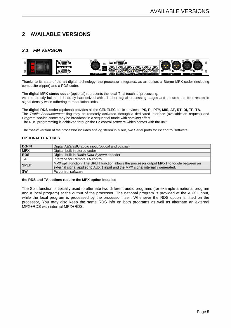
Thanks to its state-of-the-art digital technology, the processor integrates, as an option, a Stereo MPX coder (including composite clipper) and a RDS coder. The digital MPX stereo coder (optional) represents the ideal ‘final touch’ of processing. As it is directly built-in, it is totally harmonized with all other signal processing stages and ensures the best results in signal density while adhering to modulation limits. The digital RDS coder (optional) provides all the CENELEC basic services : PS, PI, PTY, M/S, AF, RT, DI, TP, TA. The Traffic Announcement flag may be remotely activated through a dedicated interface (available on request) and Program service Name may be broadcast in a sequential mode with scrolling effect. The RDS programming is achieved through the Pc control software which comes with the unit. The ‘basic’ version of the processor includes analog stereo in & out, two Serial ports for Pc control software. OPTIONAL FEATURES DG-IN Digital AES/EBU audio input (optical and coaxial) MPX Digital, built-in stereo coder RDS Digital, built-in Radio Data System encoder TA Interface for Remote TA control
SPLIT MPX split function. The SPLIT function allows the processor output MPX1 to toggle between an external signal applied to AUX 1 input and the MPX signal internally generated.
SW Pc control software the RDS and TA options require the MPX option installed The Split function is tipically used to alternate two different audio programs (for example a national program and a local program) at the output of the processor. The national program is provided at the AUX1 input, while the local program is processed by the processor itself. Whenever the RDS option is fitted on the processor, You may also keep the same RDS info on both programs as well as alternate an external MPX+RDS with internal MPX+RDS.
AVAILABLE VERSIONS
Page 6
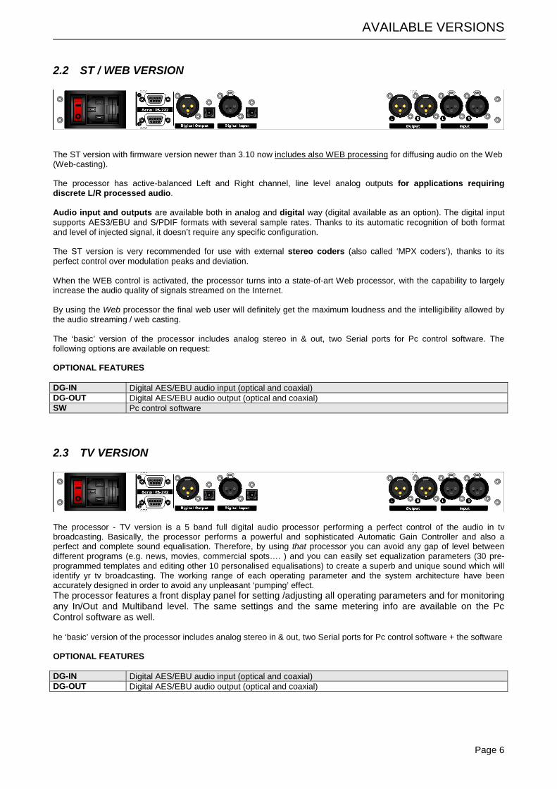
2.2 ST / WEB VERSION
The ST version with firmware version newer than 3.10 now includes also WEB processing for diffusing audio on the Web (Web-casting). The processor has active-balanced Left and Right channel, line level analog outputs for applications requiring discrete L/R processed audio. Audio input and outputs are available both in analog and digital way (digital available as an option). The digital input supports AES3/EBU and S/PDIF formats with several sample rates. Thanks to its automatic recognition of both format and level of injected signal, it doesn’t require any specific configuration. The ST version is very recommended for use with external stereo coders (also called ‘MPX coders’), thanks to its perfect control over modulation peaks and deviation. When the WEB control is activated, the processor turns into a state-of-art Web processor, with the capability to largely increase the audio quality of signals streamed on the Internet. By using the Web processor the final web user will definitely get the maximum loudness and the intelligibility allowed by the audio streaming / web casting. The ‘basic’ version of the processor includes analog stereo in & out, two Serial ports for Pc control software. The following options are available on request: OPTIONAL FEATURES DG-IN Digital AES/EBU audio input (optical and coaxial) DG-OUT Digital AES/EBU audio output (optical and coaxial) SW Pc control software
2.3 TV VERSION
The processor - TV version is a 5 band full digital audio processor performing a perfect control of the audio in tv broadcasting. Basically, the processor performs a powerful and sophisticated Automatic Gain Controller and also a perfect and complete sound equalisation. Therefore, by using that processor you can avoid any gap of level between different programs (e.g. news, movies, commercial spots…. ) and you can easily set equalization parameters (30 pre-programmed templates and editing other 10 personalised equalisations) to create a superb and unique sound which will identify yr tv broadcasting. The working range of each operating parameter and the system architecture have been accurately designed in order to avoid any unpleasant ‘pumping’ effect. The processor features a front display panel for setting /adjusting all operating parameters and for monitoring any In/Out and Multiband level. The same settings and the same metering info are available on the Pc Control software as well. he ‘basic’ version of the processor includes analog stereo in & out, two Serial ports for Pc control software + the software OPTIONAL FEATURES DG-IN Digital AES/EBU audio input (optical and coaxial) DG-OUT Digital AES/EBU audio output (optical and coaxial)
FM VERSION - BLOCK DIAGRAM
Page 7
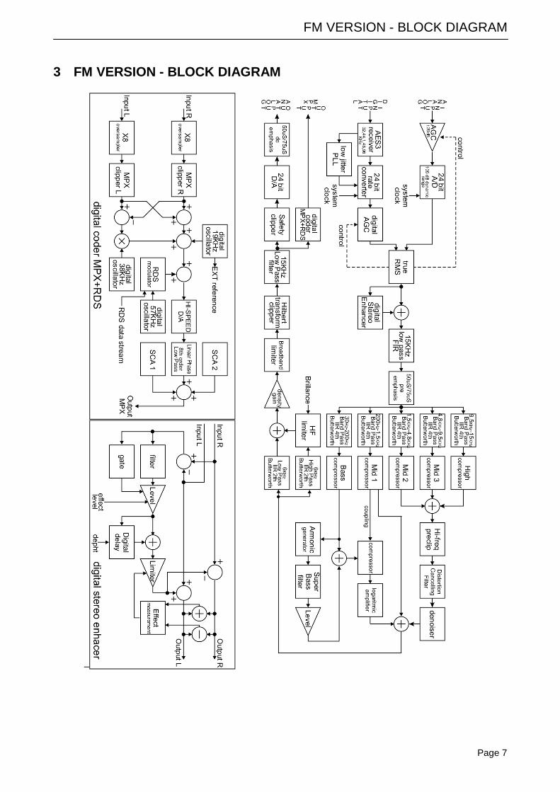
3 FM VERSION - BLOCK DIAGRAM
–
ST / WEB VERSION – BLOCK DIAGRAM
Page 8
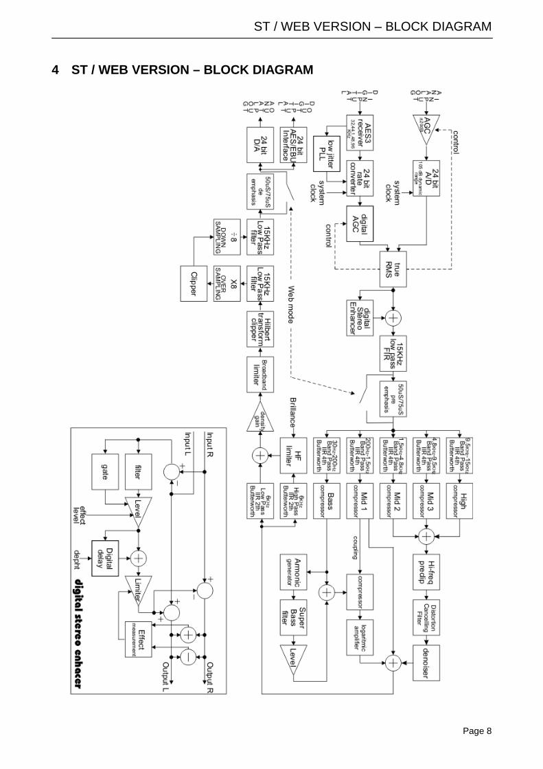
4 ST / WEB VERSION – BLOCK DIAGRAM
TV VERSION – BLOCK DIAGRAM
Page 9
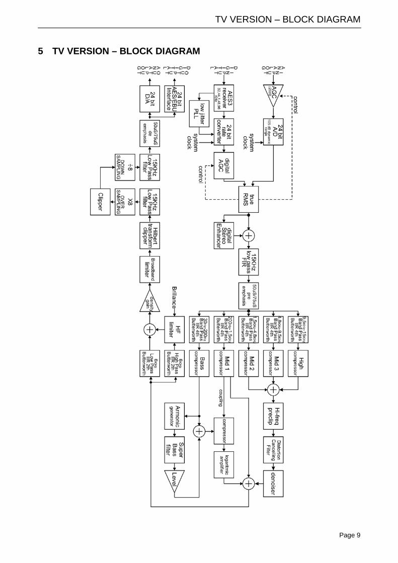
5 TV VERSION – BLOCK DIAGRAM
SAFETY WARNINGS / ISTRUZIONI PER LA SICUREZZA
Page 10
6 SAFETY WARNINGS / ISTRUZIONI PER LA SICUREZZA
SAFETY WARNINGS
CONSIGNES DE SÉCURITÉ IMPORTANTES
ISTRUZIONI IMPORTANTI PER LA SICUREZZA
WICHTIGE SICHERHEITSHINWEISE
INSTRUCCIONES IMPORTANTES DE SEGURIDAD
(Rel. 1.2)
6.1 FOREWORD For your own safety and to avoid invalidation of the warranty all text marked with these Warning Symbols should be read carefully.
Information in this manual is subject to change without notice and does not represent a commitment on the part of the vendor. The manufacturer shall not be liable for any loss or damage whatsoever arising from the use of information or any error contained in this manual, or through any mis-operation or fault in hardware contained in the product. It is recommended that all maintenance and service on the product should be carried out by the manufacturer or its authorised agents. The manufacturer cannot accept any liability whatsoever for any loss or damage caused by service, maintenance or repair by unauthorised personnel.
SAFETY WARNINGS
Page 11
7 SAFETY WARNINGS The installation and servicing instructions in this manual are for use by qualified personnel only. - Read All Instructions. All safety and operating instructions must be read before operating the product. They also
must be retained for future reference, as it contains a number of useful hints for determining the best combination of equipment settings for Yr particular application.
- Heed All Warnings. All warnings on the product and those listed in the operating instructions must be adhered to.
- Heat. This product must be situated away from any heat sources such as radiators or other products (including power amplifiers or transmitters) that produce heat.
- Power Sources. This product must be operated from the type of power source indicated on the marking label and in the installation instructions. If you are not sure of the type of power supplied to your facility, consult your local power company. Make sure the AC main voltage corresponds to that indicated in the technical specifications. If a different voltage (ex. 110/115 VAC) is available, open the equipment closure and set the voltage switch on the main supply circuit, located behind the AC socket
- Power Cord Protection. Power supply cords must be routed so that they are not likely to be walked on nor pinched by items placed upon or against them. Pay particular attention to the cords at AC wall plugs and convenience receptacles, and at the point where the cord plugs into the product
- Use only with a cart, stand, tripod, bracket, or table specified by the manufacturer, or sold with the apparatus. When a cart is used, use caution when moving the cart/apparatus combination to avoid injury from tip-over.
- Lightning. For added protection for this product during a lightning storm, or when it is left unattended and unused for long periods of time, unplug it from the AC wall outlet and the audio connections. This will prevent damage to the product due to lightning and power line surges
- Installation. Configuration and installation should only be carried out by a competent installation engineer
- Cabling. Using high quality wires, well protected. Make sure the cable integrity.
This symbol alerts you to the presence of dangerous voltage inside the closure – voltage which may be sufficient to constitute a risk of shock. Do not perform any servicing other than that contained in the operating instructions. Refer all servicing to qualified personnel
The exclamation point within an equilateral triangle is intended to alert the user to the presence of important operating and maintenance (servicing) instructions in the literature accompanying the appliance.
Do not change the voltage setting or replace the mains fuse without first turning the unit off and unplugging the mains cord
Make sure the AC main voltage corresponds to that indicated in the technical specifications. THIS APPARATUS MUST BE EARTHED !
To avoid risk of fire use the correct value fuse, as indicated on the label stuck on the right side of the unit.
This apparatus uses a single pole mains switch and does therefore not separate the unit completely from the mains power. To completely separate from mains power (f.i. in the event of danger) unplug mains power cord. As the MAINS plug is the disconnect device, the disconnect device shall remain readily operable.
CONSIGNES DE SÉCURITÉ IMPORTANTES
Page 12
8 CONSIGNES DE SÉCURITÉ IMPORTANTES - Lire ces consignes
- Conserver ces consignes
- Observer tous les avertissements
- Suivre toutes les consignes
- Ne pas utiliser cet appareil à proximité de l’eau
- Ne pas obstruer les ouvertures de ventilation. Installer en respectant les consignes du fabricant
- Ne pas installer à proximité d'une source de chaleur telle qu'un radiateur, une bouche de chaleur, un poêle ou d'autres appareils (dont les amplificateurs) produisant de la chaleur.
- Ne pas annuler la sécurité de la fiche de terre, la troisième branche est destinée à la sécurité. Si la fiche fournie ne s'adapte pas à la prise électrique, demander à un électricien de remplacer la prise hors normes.
- Protéger le cordon d'alimentation afin que personne ne marche dessus et que rien ne le pince, en particulier aux fiches, aux prises de courant et au point de sortie de l’appareil
- Utiliser uniquement les accessoires spécifiés par le fabricant
- Utiliser uniquement avec un chariot, un support ou une table spécifié par le fabricant ou vendu avec l’appareil. Si un chariot est utilisé, déplacer l’ensemble chariot–appareil avec précaution afin de ne pas le renverser, ce qui pourrait entraîner des blessures
- Débrancher l’appareil pendant les orages ou quand il ne sera pas utilisé pendant longtemps.
- Confier toute réparation à du personnel qualifié. Des réparations sont nécessaires si l’appareil est endommagé d’une façon quelconque, par exemple: cordon ou prise d’alimentation endommagé, liquide renversé ou objet tombé à l’intérieur de l’appareil, exposition de l’appareil à la pluie ou à l’humidité, appareil qui ne marche pas normalement ou que l’on a fait tomber.
- NE PAS exposer cet appareil aux égouttures et aux éclaboussements. Ne pas poser des objets contenant de l'eau, comme des vases, sur l'appareil
Ce symbole indique la présence d'une tension dangereuse dans l'appareil constituant un risque de choc électrique.
Ce symbole indique que la documentation fournie avec l'appareil contient des instructions d'utilisation et d'entretien importantes.
Avant de modifier le commutateur de changement de tension ou replacer le fusible il faut débrancher l’appareil de la prise électrique. Pendant son usage, l’appareil doit etre branchee à la prise de terre
Utiliser le fusible principal AC avec le valeur qui est indiquée sur l'étiquette collée sur le coffret.
Assurez-vous que la tension principale AC correspond à celle indiquée dans les spécifications techniques.
L’interrupteur d’alimentation interrompt un pôle du réseau d’alimentation excepté le conducteur de terre de protection. En cas de danger, debrancher le cordon d'alimentation. Parce que la prise du réseau de alimentation est utilisée comme dispositif de déconnexion, ce dispositif doit demeuré aisément accessible
ISTRUZIONI IMPORTANTI PER LA SICUREZZA
Page 13
9 ISTRUZIONI IMPORTANTI PER LA SICUREZZA - Leggere le presenti istruzioni
- Conservare queste istruzioni
- Osservare tutte le avvertenze
- Seguire scrupolosamente tutte le istruzioni
- Non usare questo apparecchio in prossimità di acqua
- Non ostruire alcuna apertura per il raffreddamento. Installare l’apparecchio seguendo le istruzioni
- Non installare l'apparecchio accanto a fonti di calore quali radiatori, aperture per l'afflusso di aria calda, forni o altri apparecchi (amplificatori inclusi) che generino calore
- Non rimuovere il terminale di connessione a terra sul cordone di alimentazione: esso ha lo scopo di tutelare l’incolumità dell’utilizzatore. Se la spina in dotazione non si adatta alla presa di corrente, rivolgersi ad un elettricista per far eseguire le modifiche necessarie.
- Evitare di calpestare il cavo di alimentazione o di comprimerlo, specialmente in corrispondenza della spina e del punto di inserzione sull’apparato.
- Utilizzare solo dispositivi di collegamento e gli accessori specificati dal produttore.
- Utilizzare l’apparecchio solo con un carrello, un sostegno, una staffa o un tavolo di tipo specificato dal produttore o venduto insieme all’apparecchio. Se si utilizza un carrello, fare attenzione negli spostamenti per evitare infortuni causati da ribaltamenti del carrello stesso.
- Scollegare l’apparecchio dalla presa di corrente durante i temporali o quando inutilizzato a lungo
- Per qualsiasi intervento, rivolgersi a personale di assistenza qualificato. È’ necessario intervenire sull’apparecchio ogniqualvolta si verificano danneggiamenti di qualsiasi natura. Ad esempio, la spina o il cavo di alimentazione sono danneggiati, è entrato liquido nell’apparecchio o sono caduti oggetti su di esso, l’apparecchio è stato esposto alla pioggia o all’umidità, non funziona normalmente o è caduto.
- Non esporre a sgocciolamenti o spruzzi. Non appoggiare sull'apparecchio oggetti pieni di liquidi, ad esempio vasi da fiori.
Questo simbolo indica la presenza di alta tensione all'interno dell'apparecchio, che comporta rischi di scossa elettrica.
Questo simbolo indica la presenza di istruzioni importanti per l'uso e la manutenzione nella documentazione in dotazione all'apparecchio.
Non sostituire il fusibile o cambiare la tensione di alimentazione senza aver prima scollegato il cordone di alimentazione. L’APPARATO DEVE ESSERE CONNESSO A TERRA.
Sostituire il fusibile generale con uno di identico valore, come indicato sulla etichetta applicata sul mobile dell’apparato
Assicurarsi che la tensione di rete corrisponda a quella per la quale è configurato l’apparecchio
Questo apparato utilizza un interruttore di alimentazione di tipo unipolare e l’isolamento dalla rete elettrica non è pertanto completo. Per ottenere un isolamento totale (ad esempio in caso di pericolo), scollegare il cordone di alimentazione. Inoltre, poichè la spina di alimentazione è utilizzata come dispositivo di sezionamento, essa deve restare facilmente raggiungibile

WICHTIGE SICHERHEITSHINWEISE
Page 14
10 WICHTIGE SICHERHEITSHINWEISE - Diese Hinweise LESEN
- Diese Hinweise AUFHEBEN
- Alle Warnhinweise BEACHTEN
- Alle Anweisungen BEFOLGEN
- Dieses Gerät NICHT in der Nähe von Wasser verwenden
- KEINE Lüftungsöffnungen verdecken. Gemäß den Anweisungen des Herstellers einbauen
- Nicht in der Nähe von Wärmequellen, wie Heizkörpern, Raumheizungen, Herden oder anderen Geräten (einschließlich Verstärkern) installieren, die Wärme erzeugen
- Die Schutzfunktion des Schukosteckers NICHT umgehen. Bei Steckern für die USA gibt es polarisierte Stecker, bei denen ein Leiter breiter als der andere ist; US-Stecker mit Erdung verfügen über einen dritten Schutzleiter. Bei diesen Steckerausführungen dient der breitere Leiter bzw. der Schutzleiter Ihrer Sicherheit. Wenn der mitgelieferte Stecker nicht in die Steckdose passt, einen Elektriker mit dem Austauschen der veralteten Steckdose beauftragen
- VERHINDERN, dass das Netzkabel gequetscht oder darauf getreten wird, insbesondere im Bereich der Stecker, Netzsteckdosen und an der Austrittsstelle vom Gerät
- NUR das vom Hersteller angegebene Zubehör und entsprechende Zusatzgeräte verwenden.
- NUR in Verbindung mit einem vom Hersteller angegebenen oder mit dem Gerät verkauften Transportwagen, Stand, Stativ, Träger oder Tisch verwenden. Wenn ein Transportwagen verwendet wird, beim Verschieben der Transportwagen-Geräte- Einheit vorsichtig vorgehen, um Verletzungen durch Umkippen
- Das Netzkabel dieses Geräts während Gewittern oder bei längeren Stillstandszeiten aus der Steckdose ABZIEHEN.
- Alle Reparatur- und Wartungsarbeiten von qualifiziertem Kundendienstpersonal DURCHFÜHREN LASSEN. Kundendienst ist erforderlich, wenn das Gerät auf irgendwelche Weise beschädigt wurde, z.B. wenn das Netzkabel oder der Netzstecker beschädigt wurden, wenn Flüssigkeiten in das Gerät verschüttet wurden oder Fremdkörper hineinfielen, wenn das Gerät Regen oder Feuchtigkeit ausgesetzt war, nicht normal funktioniert oder fallen gelassen wurde.
- Dieses Gerät vor Tropf- und Spritzwasser SCHÜTZEN. KEINE mit Wasser gefüllten Gegenstände wie zum Beispiel Vasen auf das Gerät STELLEN.
Dieses Symbol zeigt an, dass gefährliche Spannungswerte, die ein Stromschlagrisiko darstellen, innerhalb dieses Geräts auftreten.
Dieses Symbol zeigt an, dass das diesem Gerät beiliegende Handbuch wichtige Betriebs- und Wartungsanweisungen enthält.
Vor Änderung der Netzspannung oder Sicherungswechsel Netzkabel trennen. Das Gerät muss für den Betrieb geerdet werden.
Hauptsicherung nur mit einer gleichwertigen austauschen (s. entsprechende Etikette).
Vor Einschalten Netzspannungseinstellung am Gerät überprüfen bzw. anpassen.
Inpoliger Netzschalter. In Notfälle oder für Wartungsarbeiten Netzkabel trennen. Der Netzstecker fungiert auch als Trennelement muss deshalb zugänglich bleiben
INSTRUCCIONES IMPORTANTES DE SEGURIDAD
Page 15
11 INSTRUCCIONES IMPORTANTES DE SEGURIDAD - LEA estas instrucciones
- CONSERVE estas instrucciones
- PRESTE ATENCION a todas las advertencias.
- SIGA todas las instrucciones
- NO utilice este aparato cerca del agua
- NO obstruya ninguna de las aberturas de ventilación. Instálese según lo indicado en las instrucciones del fabricante
- No instale el aparato cerca de fuentes de calor tales como radiadores, registros de calefacción, estufas u otros aparatos (incluyendo amplificadores) que produzcan calor
- NO anule la función de seguridad del enchufe polarizado o con clavija de puesta a tierra. Un enchufe polarizado tiene dos patas, una más ancha que la otra. Un enchufe con puesta a tierra tiene dos patas y una tercera clavija con puesta a tierra. La pata más ancha o la tercera clavija se proporciona para su seguridad. Si el toma corriente no es del tipo apropiado para el enchufe, consulte a un electricista para que sustituya el toma corriente de estilo anticuado
- PROTEJA el cable eléctrico para evitar que personas lo pisen o estrujen, particularmente en sus enchufes, en los toma corrientes y en el punto en el cual sale del aparato
- UTILICE únicamente los accesorios especificados por el fabricante
- UTILICESE únicamente con un carro, pedestal, escuadra o mesa del tipo especificado por el fabricante o vendido con el aparato. Si se usa un carro, el mismo debe moverse con sumo cuidado para evitar que se vuelque con el aparato
- DESENCHUFE el aparato durante las tormentas eléctricas, o si no va a ser utilizado por un lapso prolongado.
- TODA reparación debe ser llevada a cabo por técnicos calificados. El aparato requiere reparación si ha sufrido cualquier tipo de daño, incluyendo los daños al cordón o enchufe eléctrico, si se derrama líquido sobre el aparato o si caen objetos en su interior, si ha sido expuesto a la lluvia o la humedad, si no funciona de modo normal, o si se ha caído.
- NO exponga este aparato a chorros o salpicaduras de líquidos. NO coloque objetos llenos con líquido, tales como floreros, sobre el aparato .
Este símbolo indica que la unidad contiene niveles de voltaje peligrosos que representan un riesgo de choques eléctricos.
Este símbolo indica que la literatura que acompaña a esta unidad contiene instrucciones importantes de funcionamiento y mantenimiento.
Antes de cambiar la alimentacion de voltaje o de cambiar el fusible, desconecte el cable de alimentacion. Para reducir el riesgo de descargas electricas, esta unidad debe ser conectada a tierra.
Remplaze el fusible con lo mismo, que corresponde a lo indicado en el panel del equipo.
Antes de encender, controlar que la linea de alimentacion de voltaje corresponda a la indicada
El interruptor de alimentación es unipolar. En el caso de peligro, desconecte el cable de alimentación. Porque la clavija de conexion a red sirve por la desconection de la unidad, la clavija debe ser ubicada en proximidad de la unidad
UNPACKING AND INSPECTION ENG
Page 16
12 UNPACKING AND INSPECTION Your equipment was packed carefully at the factory in a container designed to protect the unit during shipment. Nevertheless, we recommend making a careful inspection of the shipping carton and the contents for any signs of physical damage. Damage & Claims If damage is evident, do not discard the container or packing material. Contact your carrier immediately to file a claim for damages. Customarily, the carrier requires you, the consignee, to make all damage claims. It will be helpful to retain the shipping documents and the waybill number. Save all packing materials! If You should ever have to ship the unit (e.g. for servicing), it is best to ship it in the original carton with its packing materials because both the carton and packing material have been carefully designed to protect the unit. Under normal conditions no user maintenance or calibration are required. Internal links and preset controls may be set to configure the unit during installation. Any service work required should be carried out by qualified service personnel only. We are able to offer further product support through our worldwide network of approved dealers and service agents.
To help us provide the most efficient service please would you keep a record of the unit serial number, and date and place of purchase to be quoted in any communication regarding this product.
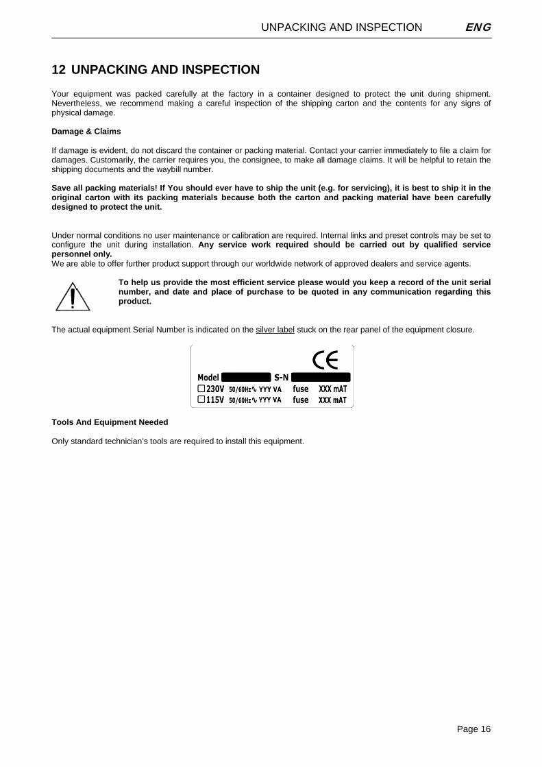
The actual equipment Serial Number is indicated on the silver label stuck on the rear panel of the equipment closure.
Tools And Equipment Needed Only standard technician’s tools are required to install this equipment.

FIRST INSTALLATION RECOMMENDATIONS ENG
Page 17
13 FIRST INSTALLATION RECOMMENDATIONS
13.1 POWER SUPPLY CABLE A power supply cable of approx. 2 mt length is supplied with the device, which has a moulded IEC plug attached – this is a legal requirement. The type of plug for the power supply depends on the country in which it is delivered. If for any reason, you need to use this appliance with a different plug, you should use the following wiring guidelines in replacing the exsisting plug with the new one:
Earth Green, or green and yellow Neutral (N) Blue Live (L) Brown
Supply cables should be laid in such a manner that one does not step or walk on them. They should not be squashed by any objects.
THIS EQUIPMENT MUST BE EARTHED. The chassis is always connected to mains earth to ensure your safety: check your mains wiring and earthing before switching on.
13.2 AC MAINS VOLTAGE SETTING (230 V / 115 V)
BE SURE THAT THE UNIT IS SET TO THE CORRECT MAINS/LINE VOLTAGE FOR YOUR COUNTRY BEFORE PLUGGING IT INTO THE WALL OUTLET !
The actual Mains voltage is indicated on the label stuck on the equipment closure. Should the type of power at the operation location not be known, please contact your dealer or electricity company.
If, for some reason, the unit is to be operated at a mains input voltage which is different to that as supplied, you need to open the top cover and set properly the voltage change-over switch which is located inside, close to the transformer. You also need to replace the AC main fuse, according to information provided on the external label or on the Technical Specifications table at the end of this user manual.
CAUTION: TO REDUCE THE RISK OF ELECTRICAL SHOCK, ALWAYS DISCONNECT THE AC MAINS CABLE BEFORE ALTERING THE CHANGE-OVER SWITCH. NO USER SERVICEABLE PARTS INSIDE. REFER SERVICING TO QUALIFIED SERVICE PERSONNEL.
FIRST INSTALLATION RECOMMENDATIONS ENG
Page 18
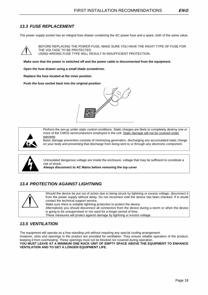
13.3 FUSE REPLACEMENT The power supply socket has an integral fuse drawer containing the AC power fuse and a spare, both of the same value.
BEFORE REPLACING THE POWER FUSE, MAKE SURE YOU HAVE THE RIGHT TYPE OF FUSE FOR THE VOLTAGE TO BE PROTECTED. USING WRONG FUSE TYPE WILL RESULT IN INSUFFICIENT PROTECTION.
Make sure that the power is switched off and the power cable is disconnected from the equipment. Open the fuse drawer using a small blade screwdriver. Replace the fuse located at the inner position Push the fuse socket back into the original position
Perform the set-up under static control conditions. Static charges are likely to completely destroy one or more of the CMOS semiconductors employed in the unit. Static damage will not be covered under warranty. Basic damage prevention consists of minimizing generation, discharging any accumulated static charge on your body and preventing that discharge from being sent to or through any electronic component.
Uninsulated dangerous voltage are inside the enclosure, voltage that may be sufficient to constitute a risk of shock. Always disconnect to AC Mains before removing the top cover
13.4 PROTECTION AGAINST LIGHTNING
Should the device be put out of action due to being struck by lightning or excess voltage, disconnect it from the power supply without delay. Do not reconnect until the device has been checked. If in doubt contact the technical support service. Make sure there is suitable lightning protection to protect the device. Alternatively you should disconnect all connectors from the device during a storm or when the device is going to be unsupervised or not used for a longer period of time. These measures will protect against damage by lightning or excess voltage.
13.5 VENTILATION The equipment will operate as a free-standing unit without requiring any special cooling arrangement. However, slots and openings in the product are provided for ventilation. They ensure reliable operation of the product, keeping it from overheating. These openings must not be blocked nor covered during operation. YOU MUST LEAVE AT A MINIMUM ONE RACK UNIT OF EMPTY SPACE ABOVE THE EQUIPMENT TO ENHANCE VENTILATION AND TO GET A LONGER EQUIPMENT LIFE.
I/O BASIC SETTINGS ENG
Page 19
14 I/O BASIC SETTINGS
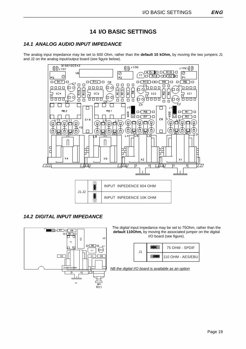
14.1 ANALOG AUDIO INPUT IMPEDANCE The analog input impedance may be set to 600 Ohm, rather than the default 10 kOhm, by moving the two jumpers J1 and J2 on the analog input/output board (see figure below).
J1-J2
INPUT INPEDENCE 604 OHM
INPUT INPEDENCE 10K OHM
14.2 DIGITAL INPUT IMPEDANCE
The digital input impedance may be set to 75Ohm, rather than the default 110Ohm, by moving the associated jumper on the digital
I/O board (see figure).
J1
110 OHM - AES/EBU
75 OHM - SPDIF
NB the digital I/O board is available as an option
I/O BASIC SETTINGS ENG
Page 20
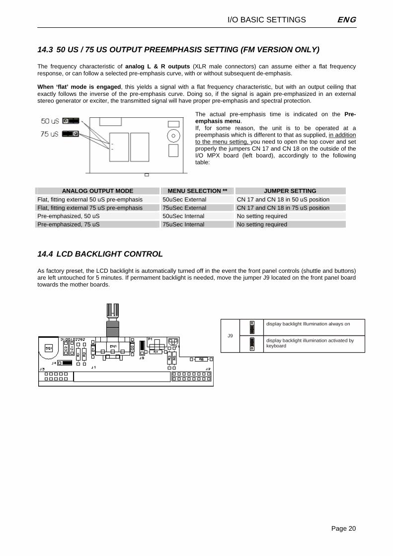
14.3 50 US / 75 US OUTPUT PREEMPHASIS SETTING (FM VERSION ONLY) The frequency characteristic of analog L & R outputs (XLR male connectors) can assume either a flat frequency response, or can follow a selected pre-emphasis curve, with or without subsequent de-emphasis. When ‘flat’ mode is engaged, this yields a signal with a flat frequency characteristic, but with an output ceiling that exactly follows the inverse of the pre-emphasis curve. Doing so, if the signal is again pre-emphasized in an external stereo generator or exciter, the transmitted signal will have proper pre-emphasis and spectral protection.
The actual pre-emphasis time is indicated on the Pre-emphasis menu. If, for some reason, the unit is to be operated at a preemphasis which is different to that as supplied, in addition to the menu setting, you need to open the top cover and set properly the jumpers CN 17 and CN 18 on the outside of the I/O MPX board (left board), accordingly to the following table:
ANALOG OUTPUT MODE MENU SELECTION ** JUMPER SETTING Flat, fitting external 50 uS pre-emphasis 50uSec External CN 17 and CN 18 in 50 uS position Flat, fitting external 75 uS pre-emphasis 75uSec External CN 17 and CN 18 in 75 uS position Pre-emphasized, 50 uS 50uSec Internal No setting required Pre-emphasized, 75 uS 75uSec Internal No setting required
14.4 LCD BACKLIGHT CONTROL As factory preset, the LCD backlight is automatically turned off in the event the front panel controls (shuttle and buttons) are left untouched for 5 minutes. If permament backlight is needed, move the jumper J9 located on the front panel board towards the mother boards.
J9
display backlight Illumination always on
display backlight illumination activated by keyboard
MPX BOARD CONNECTIONS (FM VERSION ONLY) ENG
Page 21
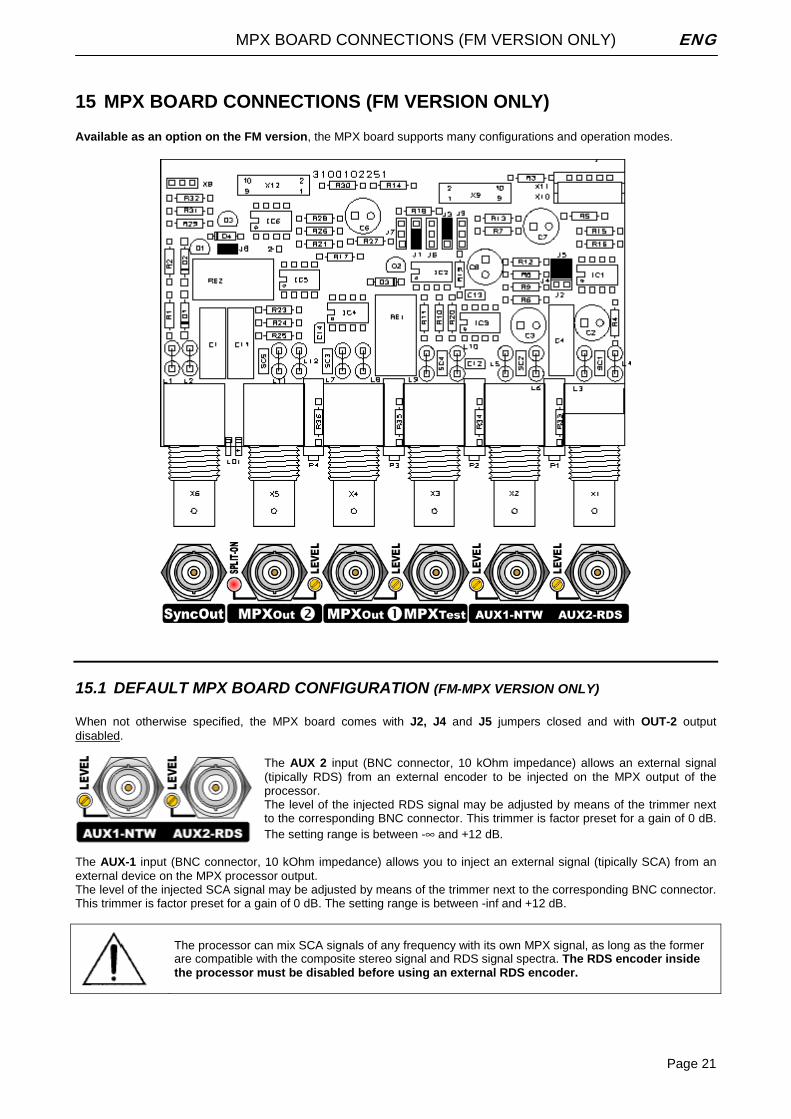
15 MPX BOARD CONNECTIONS (FM VERSION ONLY) Available as an option on the FM version, the MPX board supports many configurations and operation modes.
15.1 DEFAULT MPX BOARD CONFIGURATION (FM-MPX VERSION ONLY) When not otherwise specified, the MPX board comes with J2, J4 and J5 jumpers closed and with OUT-2 output disabled.
The AUX 2 input (BNC connector, 10 kOhm impedance) allows an external signal (tipically RDS) from an external encoder to be injected on the MPX output of the processor. The level of the injected RDS signal may be adjusted by means of the trimmer next to the corresponding BNC connector. This trimmer is factor preset for a gain of 0 dB. The setting range is between -∞ and +12 dB.
The AUX-1 input (BNC connector, 10 kOhm impedance) allows you to inject an external signal (tipically SCA) from an external device on the MPX processor output. The level of the injected SCA signal may be adjusted by means of the trimmer next to the corresponding BNC connector. This trimmer is factor preset for a gain of 0 dB. The setting range is between -inf and +12 dB.
The processor can mix SCA signals of any frequency with its own MPX signal, as long as the former are compatible with the composite stereo signal and RDS signal spectra. The RDS encoder inside the processor must be disabled before using an external RDS encoder.
MPX BOARD CONNECTIONS (FM VERSION ONLY) ENG
Page 22
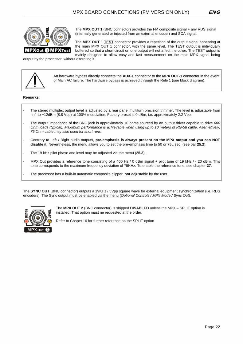
The MPX OUT 1 (BNC connector) provides the FM composite signal + any RDS signal (internally generated or injected from an external encoder) and SCA signal. The MPX OUT 1 TEST connector provides a repetition of the output signal appearing at the main MPX OUT 1 connector, with the same level. The TEST output is individually buffered so that a short circuit on one output will not affect the other. The TEST output is mainly designed to allow easy and fast measurement on the main MPX signal being
output by the processor, without alterating it.
An hardware bypass directly connects the AUX-1 connector to the MPX OUT-1 connector in the event of Main AC failure. The hardware bypass is achieved through the Relè 1 (see block diagram).
Remarks: - The stereo multiplex output level is adjusted by a rear panel multiturn precision trimmer. The level is adjustable from
-inf to +12dBm (8.8 Vpp) at 100% modulation. Factory preset is 0 dBm, i.e. approximately 2.2 Vpp. - The output impedance of the BNC jack is approximately 10 ohms sourced by an output driver capable to drive 600
Ohm loads (typical). Maximum performance is achievable when using up to 10 meters of RG-58 cable. Alternatively, 75 Ohm cable may also used for short runs.
- Contrary to Left / Right audio outputs, pre-emphasis is always present on the MPX output and you can NOT
disable it. Nevertheless, the menu allows you to set the pre-emphasis time to 50 or 75μ sec. (see par 25.2). - The 19 kHz pilot phase and level may be adjusted via the menu (25.3). - MPX Out provides a reference tone consisting of a 400 Hz / 0 dBm signal + pilot tone of 19 kHz / - 20 dBm. This
tone corresponds to the maximum frequency deviation of 75KHz. To enable the reference tone, see chapter 27. - The processor has a built-in automatic composite clipper, not adjustable by the user. The SYNC OUT (BNC connector) outputs a 19KHz / 5Vpp square wave for external equipment synchronization (i.e. RDS encoders). The Sync output must be enabled via the menu (Optional Controls / MPX Mode / Sync Out).
The MPX OUT 2 (BNC connector) is shipped DISABLED unless the MPX – SPLIT option is installed. That option must ne requested at the order. Refer to Chapet 16 for further reference on the SPLIT option.
MPXOut
MPX BOARD CONNECTIONS (FM VERSION ONLY) ENG
Page 23
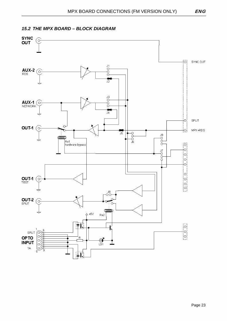
15.2 THE MPX BOARD – BLOCK DIAGRAM
THE ‘SPLIT’ MODE (FM VERSION ONLY) ENG
Page 24
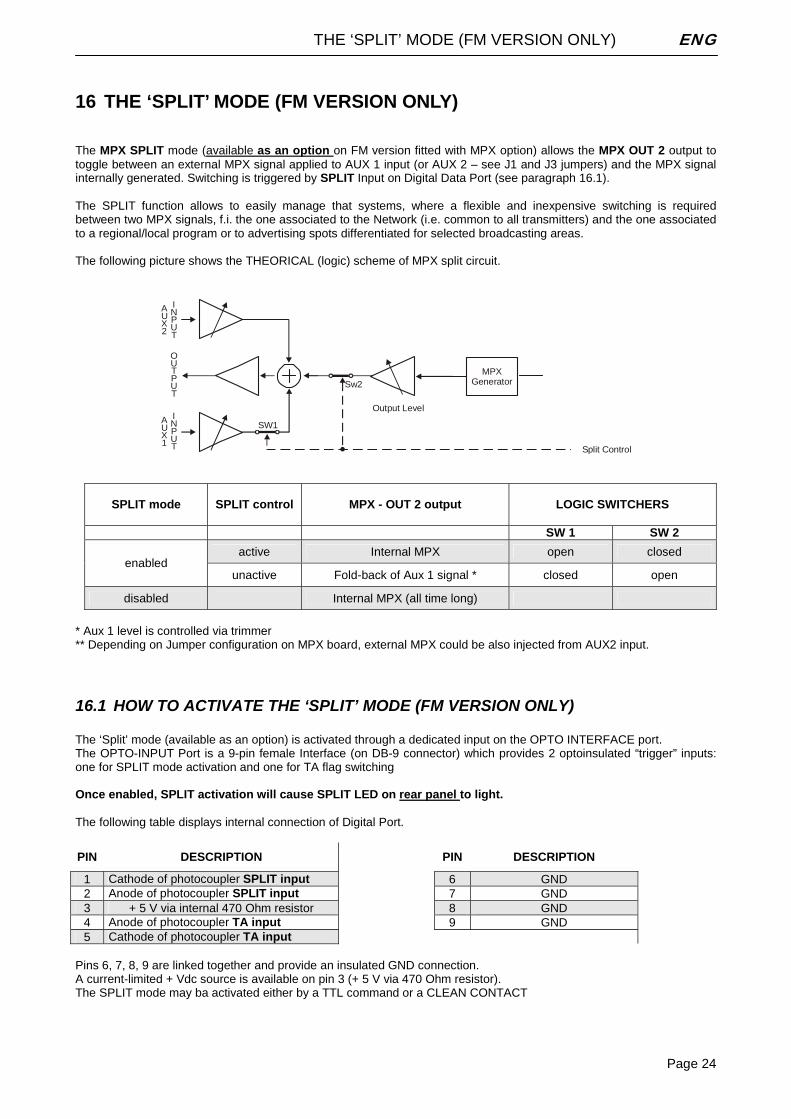
16 THE ‘SPLIT’ MODE (FM VERSION ONLY) The MPX SPLIT mode (available as an option on FM version fitted with MPX option) allows the MPX OUT 2 output to toggle between an external MPX signal applied to AUX 1 input (or AUX 2 – see J1 and J3 jumpers) and the MPX signal internally generated. Switching is triggered by SPLIT Input on Digital Data Port (see paragraph 16.1). The SPLIT function allows to easily manage that systems, where a flexible and inexpensive switching is required between two MPX signals, f.i. the one associated to the Network (i.e. common to all transmitters) and the one associated to a regional/local program or to advertising spots differentiated for selected broadcasting areas. The following picture shows the THEORICAL (logic) scheme of MPX split circuit.
AUX2
AUX1
INPUT
OUTPUT
INPUT
Output Level
SW1
Sw2
Split Control
MPX Generator
SPLIT mode
SPLIT control
MPX - OUT 2 output LOGIC SWITCHERS
SW 1 SW 2
active Internal MPX open closed enabled
unactive Fold-back of Aux 1 signal * closed open
disabled Internal MPX (all time long)
* Aux 1 level is controlled via trimmer ** Depending on Jumper configuration on MPX board, external MPX could be also injected from AUX2 input.
16.1 HOW TO ACTIVATE THE ‘SPLIT’ MODE (FM VERSION ONLY) The ‘Split’ mode (available as an option) is activated through a dedicated input on the OPTO INTERFACE port. The OPTO-INPUT Port is a 9-pin female Interface (on DB-9 connector) which provides 2 optoinsulated “trigger” inputs: one for SPLIT mode activation and one for TA flag switching Once enabled, SPLIT activation will cause SPLIT LED on rear panel to light. The following table displays internal connection of Digital Port.
PIN DESCRIPTION PIN DESCRIPTION
1 Cathode of photocoupler SPLIT input 6 GND 2 Anode of photocoupler SPLIT input 7 GND 3 + 5 V via internal 470 Ohm resistor 8 GND 4 Anode of photocoupler TA input 9 GND 5 Cathode of photocoupler TA input
Pins 6, 7, 8, 9 are linked together and provide an insulated GND connection. A current-limited + Vdc source is available on pin 3 (+ 5 V via 470 Ohm resistor). The SPLIT mode may ba activated either by a TTL command or a CLEAN CONTACT
THE ‘SPLIT’ MODE (FM VERSION ONLY) ENG
Page 25
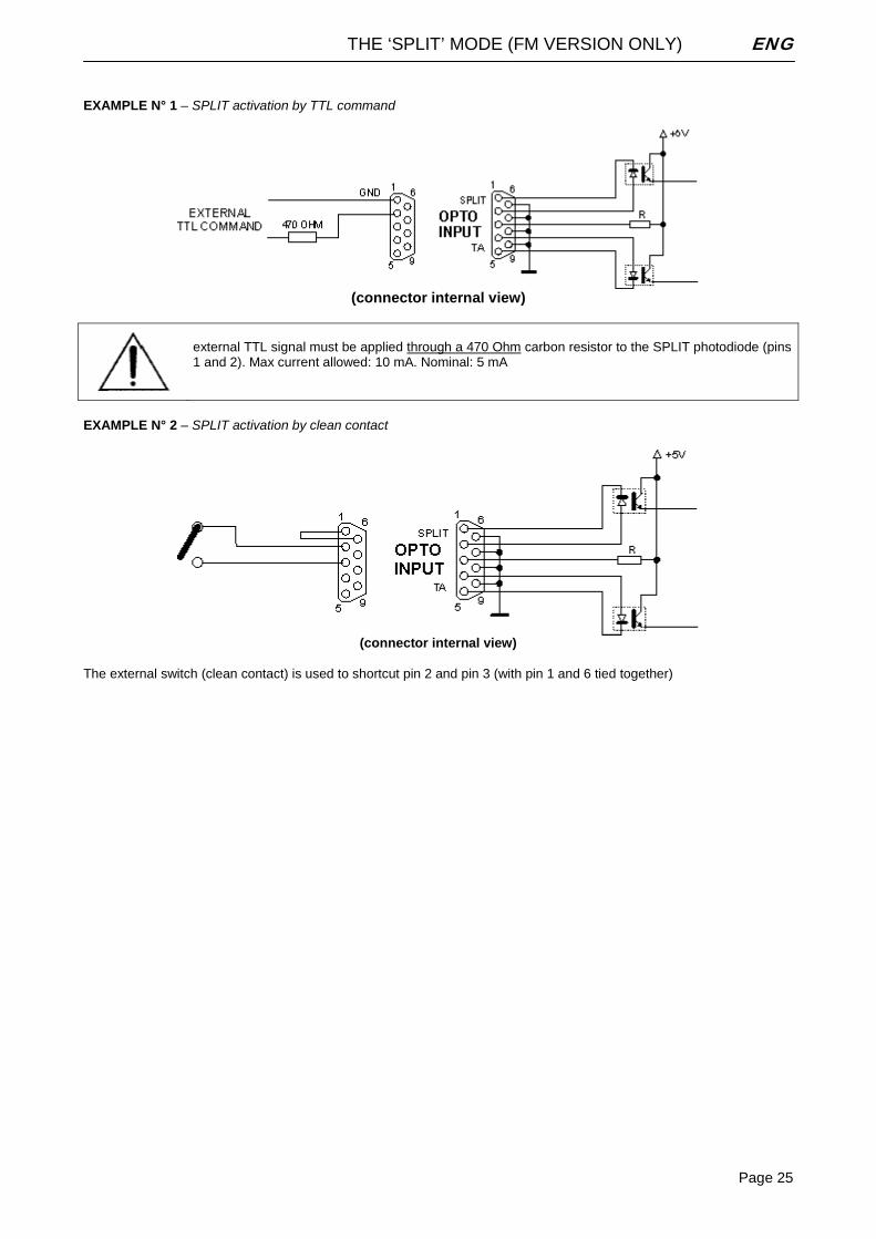
EXAMPLE N° 1 – SPLIT activation by TTL command
(connector internal view)
external TTL signal must be applied through a 470 Ohm carbon resistor to the SPLIT photodiode (pins 1 and 2). Max current allowed: 10 mA. Nominal: 5 mA
EXAMPLE N° 2 – SPLIT activation by clean contact
(connector internal view)
The external switch (clean contact) is used to shortcut pin 2 and pin 3 (with pin 1 and 6 tied together)
GENERAL DESCRIPTION ENG
Page 26
17 GENERAL DESCRIPTION
17.1 FRONT PANEL CONTROLS AND SIGNALLINGS The processor front panel contains 3 red LEDs with the following meaning: DIGITAL INPUT This LED lights up while the DIGITAL Audio input is selected (via front panel menu
or Pc Software Control). , PREEMPHASIS This LED lights up while the Preemphasis (either 50 or 75 uSec) is removed from
the processed Left and Right output XLR connectors. (NB preemphasis can NOT be removed from the MPX outputs).
WARNING this LED (normally off) lights in the following cases:
- With ‘Bypass’ or ‘Peak Reference Tone’ modes enabled - Internal Temperature exceeding 60 °C. - TA (Traffic Announcement) flag enabled (FM /RDS version only)
The processor front panel also contains two buttons, a large display MULTIFUNCTION DISPLAY See next Section LCD CONTRAST TRIMMER it sets the contrast on the multifunction display. The temperature variation could
effect the contrast, to set it, please use a small screwdriver SHUTTLE KNOB It allows to scroll the menu and modify the parameters. To modify any parameter
you need to turn the shuttle till it will appear on the display (see chapter 6). The shuuttle can also be pressed, having the same ENTER control function.
ENTER KEY it gives access to the parameters submenu and selects the new values. ESC KEY key to quit the current menu and go back to the previous one. By pressing this key
the modifications realized by accident on the selected parameter are not executed.
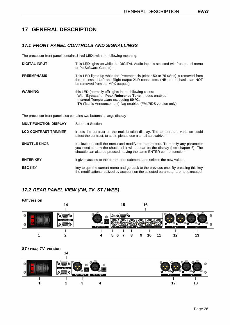
17.2 REAR PANEL VIEW (FM, TV, ST / WEB)
FM version 14 15 16 I I I
I I I I I I I I I I I I 1 2 4 5 6 7 8 9 10 11 12 13
ST / web, TV version
14 I
I I I I I I 1 2 3 4 12 13
GENERAL DESCRIPTION ENG
Page 27
1 ON/OFF Switch: main ON/OFF switch, the LED inside switches on/off accordingly. The power supply socket (use
the cord provided) has a built-in fuse drawer containing the power fuse and a spare, both of the same value: for 230 V AC the fuse is rated at 500 mA T; for 110 V AC it is rated at 630 mA T
2 RS232 Serial Port 2: This port is intended for the processor setting and programming from satellite and
unidirectional links. Supported Baud Rate: 4800. 3 Digital audio output*: This has two connectors: use the XLR for balanced coaxial connections and the tos-link for
optical connections. It provides Aes/Ebu and Spdif signals @ 48 KHz, 24 bit. 4 Digital audio input*: This has two connectors: use the XLR for balanced coaxial connections and the tos-link for
optical connections. It accepts Aes/Ebu and Spdif signals at different sampling rates 5 Sync-out*: 19KHz synchronism output at 5Vpp, to lock external equipment (such as RDS coders). It is disabled by
default and must be enabled by the menu. 6 SPLIT ON Led*: it lights on while the Split command is active (and thus the OUT 2 is on Split) 7 MPX OUT 2*: additional MPX output, driven by a special circuit ( ‘SPLIT’). It is disabled by default. Preemphasis
can NOT be removed from this MPX output 8 MPX OUT 1*: main MPX output. The trimmer near the Bnc connector tunes the MPX output level between -inf and
+12 dbu (factory preset is 0dbu). Accordingly to the current configuration, the output BNC connector will include the composite / MPX program signal with the RDS / SCA subcarrier mixed into and with or without signals injected from AUX inputs. An hardware bypass directly connect the AUX1 input to OUT1 in the event of power failure or processor switched off. Preemphasis can NOT be removed from this MPX output
9 MPX OUT 1 TEST*: provides a repetition of the output signal appearing at the main MPX OUT 1 connector, with
the same level. It may serve for measurement or as secondary MPX output. Preemphasis can NOT be removed from this MPX output
10 AUX 1 Input*: Bnc female connector. Depending on the MPX board configuration, it allow the injection of
RDS/SCA or MPX signals from external encoders/generators. The resultant signal is available on the Output connectors OUT 1 or OUT 2. Factory preset: 0dB gain.
11 AUX 2 input*: Bnc female connector. Depending on the MPX board configuration, it allow the injection of
RDS/SCA or MPX signals from external encoders/generators. The resultant signal is available on the Output connectors OUT 1 or OUT 2. Factory preset: 0dB gain.
12 ANALOG AUDIO OUTPUT: It provides the L and R processed audio signals on which it is possible to
enable/disable pre-emphasis. The level is set via menu. 13 ANALOG AUDIO INPUT: bi-channel audio input electronically balanced on XLR female. The input level is set via
menu. An hardware bypass directly connect the two input XLRs to the output ones in the event of power failure or processor switched off.
14 RS232 SERIAL PORT 1: This port is intended for the processor setting and programming by means of the
supplied Pc control software application (bidirectional connection). Supported Baud Rate: 19200. 15 OPTO INPUT PORT*: SubD 9-pin female Interface. It supports 2 optoinsulated “trigger” inputs (for TA flag toggle
and for SPLIT mode enabling) 16 RELAY OUTPUT*: Reserved for future use
* available as an option
GENERAL DESCRIPTION ENG
Page 28
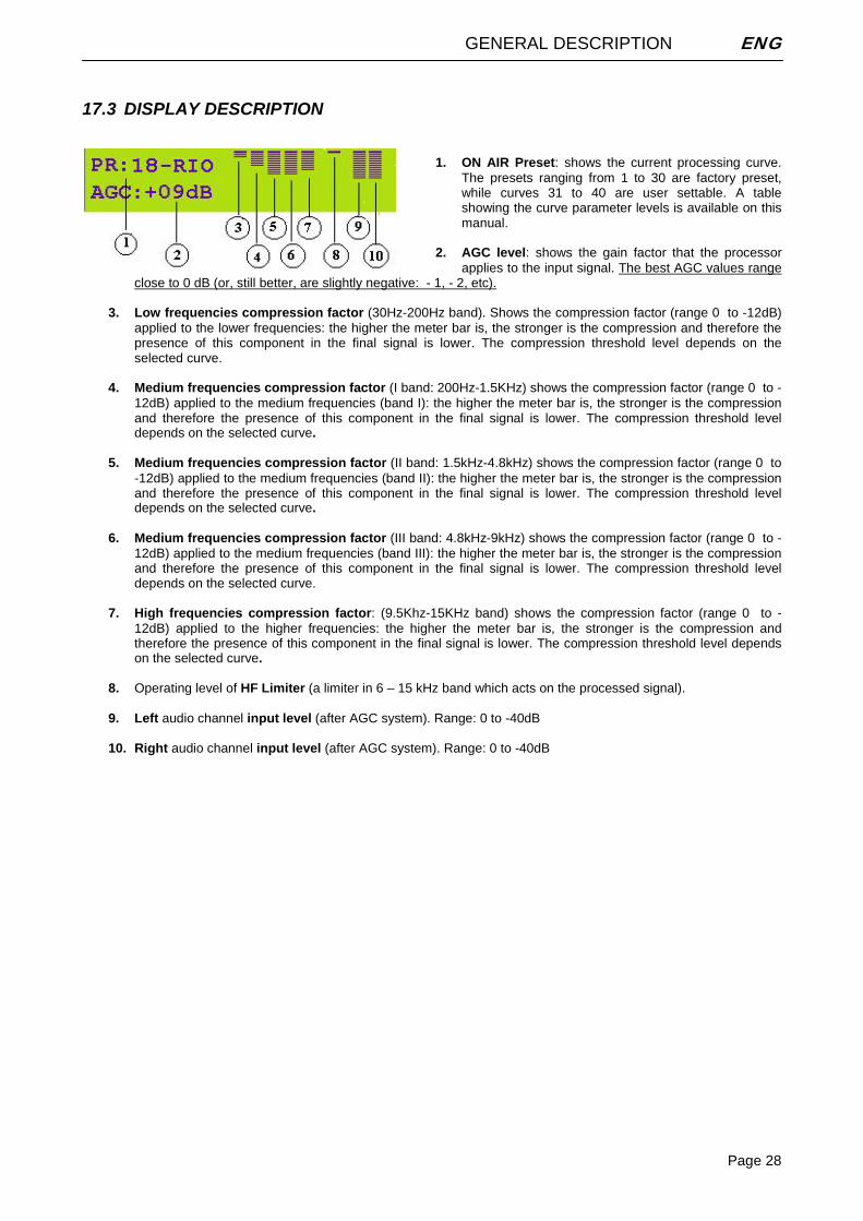
17.3 DISPLAY DESCRIPTION
1. ON AIR Preset: shows the current processing curve.
The presets ranging from 1 to 30 are factory preset, while curves 31 to 40 are user settable. A table showing the curve parameter levels is available on this manual.
2. AGC level: shows the gain factor that the processor
applies to the input signal. The best AGC values range close to 0 dB (or, still better, are slightly negative: - 1, - 2, etc).
3. Low frequencies compression factor (30Hz-200Hz band). Shows the compression factor (range 0 to -12dB)
applied to the lower frequencies: the higher the meter bar is, the stronger is the compression and therefore the presence of this component in the final signal is lower. The compression threshold level depends on the selected curve.
4. Medium frequencies compression factor (I band: 200Hz-1.5KHz) shows the compression factor (range 0 to -
12dB) applied to the medium frequencies (band I): the higher the meter bar is, the stronger is the compression and therefore the presence of this component in the final signal is lower. The compression threshold level depends on the selected curve.
5. Medium frequencies compression factor (II band: 1.5kHz-4.8kHz) shows the compression factor (range 0 to
-12dB) applied to the medium frequencies (band II): the higher the meter bar is, the stronger is the compression and therefore the presence of this component in the final signal is lower. The compression threshold level depends on the selected curve.
6. Medium frequencies compression factor (III band: 4.8kHz-9kHz) shows the compression factor (range 0 to -
12dB) applied to the medium frequencies (band III): the higher the meter bar is, the stronger is the compression and therefore the presence of this component in the final signal is lower. The compression threshold level depends on the selected curve.
7. High frequencies compression factor: (9.5Khz-15KHz band) shows the compression factor (range 0 to -
12dB) applied to the higher frequencies: the higher the meter bar is, the stronger is the compression and therefore the presence of this component in the final signal is lower. The compression threshold level depends on the selected curve.
8. Operating level of HF Limiter (a limiter in 6 – 15 kHz band which acts on the processed signal).
9. Left audio channel input level (after AGC system). Range: 0 to -40dB
10. Right audio channel input level (after AGC system). Range: 0 to -40dB
AUDIO I/O AND SERIAL PORT WIRING ENG
Page 29
18 AUDIO I/O AND SERIAL PORT WIRING Where possible use balanced connections for the audio inputs and outputs to minimise noise pick-up. Avoid running audio cables near to mains or lighting cables or thyristor dimmer units, power supplies etc. These may cause audible hum and buzz. The use of low impedance sources significantly reduces interference pick-up. Check the cables for correct wiring to avoid problems with phase reversal and unreliable connection.
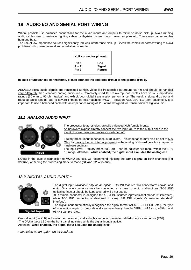
XLR connector pin-out: Pin 1 Gnd Pin 2 Signal Pin 3 Return
In case of unbalanced connections, please connect the cold pole (Pin 3) to the ground (Pin 1). AES/EBU digital audio signals are transmitted at high, video-like frequencies (at around 6MHz) and should be handled very differently than standard analog audio lines. Commonly used XLR-3 microphone cables have various impedance ratings (30 ohm to 90 ohm typical) and exhibit poor digital transmission performance. The result is signal drop out and reduced cable lengths due to severe impedance mis-matching (VSWR) between AES/EBU 110 ohm equipment. It is important to use a balanced cable with an impedance rating of 110 ohms designed for transmission of digital audio.
18.1 ANALOG AUDIO INPUT The processor features electronically balanced XLR female inputs. An hardware bypass directly connect the two input XLRs to the output ones in the event of power failure or processor switched off. Factory preset input impedance is 10 kOhm. This impedance may also be set to 600 Ohm by moving the two internal jumpers on the analog I/O board (see last chapter on hardware settings). The input level – factory preset to 0 dB – can be adjusted via menu within the +/- 6 dB range. Attention: while enabled, the digital input excludes the analog one.
NOTE: in the case of connection to MONO sources, we recommend injecting the same signal on both channels (FM version) or setting the processing mode to mono (ST and TV versions).
18.2 DIGITAL AUDIO INPUT * The digital input (available only as an option - DG-IN) features two connectors: coaxial and optic. Only one connector may be connected at a time to avoid malfunctions (TOSLINK optical connector should be kept covered while not used). XLR female connector is designed for AES/EBU sources (“professional standard” interface), while TOSLINK connector is designed to carry S/P DIF signals (“consumer standard” interface). The digital input automatically recognizes the digital format (AES, EBU, SPDIF, etc.), the type of connection (optic or coaxial) and can seamlessly handle 32KHz, 44.1KHz, 48KHz and 96KHz sample rates.
Coaxial input (on XLR) is transformer balanced, and so highly immune from external disturbances and noise (EMI). The Digital Input LED on the front panel indicates while the digital input is active. Attention: while enabled, the digital input excludes the analog input. * available as an option on all versions
AUDIO I/O AND SERIAL PORT WIRING ENG
Page 30
8.2.1 Converting between AES/EBU and S/PDIF interfaces There are a number of differences in the electrical characteristics of AES/EBU and S/PDIF interfaces which in some cases can render them completely incompatible. Although the audio data is the same in both AES/EBU and S/ PDIF interfaces, they are indeed different formats, at least in their subcode. AES converted to coax is NOT S/PDIF, and S/PDIF converted to XLR balanced is NOT AES. They are still their native format, just the transmission medium has changed. Whether they will work in your application depends on the equipment chosen and, for proper performance, XLR input should therefore not be used for connection to consumer equipment. AES/EBU uses a balanced differential line based on XLR connectors and the signal levels are 5 volts. S/P-DIF uses a coaxial unbalanced line with RCA connectors and the signal levels are around 0.5 volts. The protocol used in AES/EBU and S/PDIF is not exactly the same and that can cause problems sometimes. The basic data format of AES and S/P-DIF are identical. There is a bit in the channel status frame that tells which is which. Depending upon the setting of that bit, some bits have different meanings. For example, the bits used to describe de-emphasis in the AES/EBU protocol overlap the bits used to implement the SCMS (serial copy management system) protocol in S/P-DIF land. Furthermore, S/PDIF usually uses 75 ohm coaxial cable and RCA connectors. 75 ohm coaxial cable is inexpensive, because it is the same cable as used in video transmission. AES/EBU-interface uses the well known symmetrical connections with transformer isolation and an output impedance of 110 ohm.
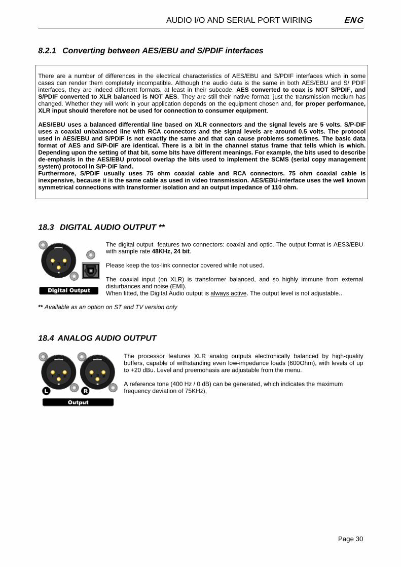
18.3 DIGITAL AUDIO OUTPUT ** The digital output features two connectors: coaxial and optic. The output format is AES3/EBU with sample rate 48KHz, 24 bit. Please keep the tos-link connector covered while not used. The coaxial input (on XLR) is transformer balanced, and so highly immune from external disturbances and noise (EMI). When fitted, the Digital Audio output is always active. The output level is not adjustable..
** Available as an option on ST and TV version only
18.4 ANALOG AUDIO OUTPUT The processor features XLR analog outputs electronically balanced by high-quality buffers, capable of withstanding even low-impedance loads (600Ohm), with levels of up to +20 dBu. Level and preemohasis are adjustable from the menu. A reference tone (400 Hz / 0 dB) can be generated, which indicates the maximum frequency deviation of 75KHz),
AUDIO I/O AND SERIAL PORT WIRING ENG
Page 31
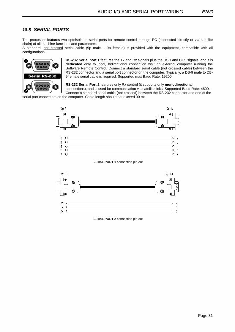
18.5 SERIAL PORTS The processor features two optoisolated serial ports for remote control through PC (connected directly or via satellite chain) of all machine functions and parameters. A standard, not crossed serial cable (9p male – 9p female) is provided with the equipment, compatible with all configurations.
RS-232 Serial port 1 features the Tx and Rx signals plus the DSR and CTS signals, and it is dedicated only to local, bidirectional connection whit an external computer running the Software Remote Control. Connect a standard serial cable (not crossed cable) between the RS-232 connector and a serial port connector on the computer. Typically, a DB-9 male to DB-9 female serial cable is required. Supported max Baud Rate: 19200. RS-232 Serial Port 2 features only Rx control (it supports only monodirectional connections), and is used for communication via satellite links. Supported Baud Rate: 4800. Connect a standard serial cable (not crossed) between the RS-232 connector and one of the
serial port connectors on the computer. Cable length should not exceed 30 mt.
SERIAL PORT 1 connection pin-out
SERIAL PORT 2 connection pin-out
BROWSING THE MENU TREE ENG
Page 32
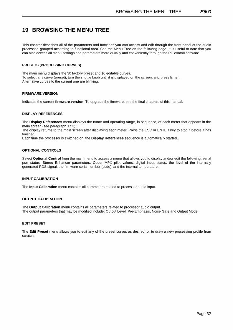
19 BROWSING THE MENU TREE This chapter describes all of the parameters and functions you can access and edit through the front panel of the audio processor, grouped according to functional area. See the Menu Tree on the following page. It is useful to note that you can also access all menu settings and parameters more quickly and conveniently through the PC control software. PRESETS (PROCESSING CURVES) The main menu displays the 30 factory preset and 10 editable curves. To select any curve (preset), turn the shuttle knob until it is displayed on the screen, and press Enter. Alternative curves to the current one are blinking. FIRMWARE VERSION Indicates the current firmware version. To upgrade the firmware, see the final chapters of this manual. DISPLAY REFERENCES The Display References menu displays the name and operating range, in sequence, of each meter that appears in the main screen (see paragraph 17.3). The display returns to the main screen after displaying each meter. Press the ESC or ENTER key to stop it before it has finished. Each time the processor is switched on, the Display References sequence is automatically started.. OPTIONAL CONTROLS Select Optional Control from the main menu to access a menu that allows you to display and/or edit the following: serial port status, Stereo Enhancer parameters, Coder MPX pilot values, digital input status, the level of the internally generated RDS signal, the firmware serial number (code), and the internal temperature. INPUT CALIBRATION The Input Calibration menu contains all parameters related to processor audio input. OUTPUT CALIBRATION The Output Calibration menu contains all parameters related to processor audio output. The output parameters that may be modified include: Output Level, Pre-Emphasis, Noise Gate and Output Mode. EDIT PRESET The Edit Preset menu allows you to edit any of the preset curves as desired, or to draw a new processing profile from scratch.
BROWSING THE MENU TREE ENG
Page 33
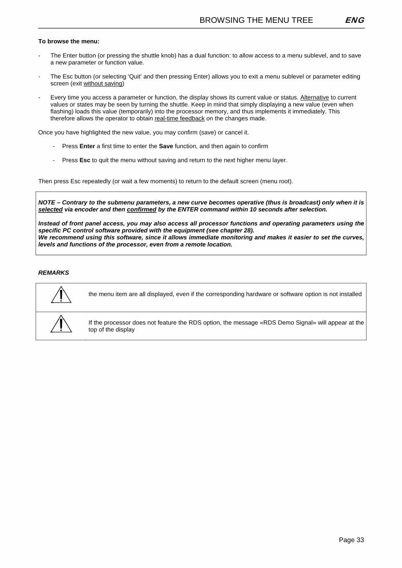
To browse the menu: - The Enter button (or pressing the shuttle knob) has a dual function: to allow access to a menu sublevel, and to save
a new parameter or function value. - The Esc button (or selecting ‘Quit’ and then pressing Enter) allows you to exit a menu sublevel or parameter editing
screen (exit without saving) - Every time you access a parameter or function, the display shows its current value or status. Alternative to current
values or states may be seen by turning the shuttle. Keep in mind that simply displaying a new value (even when flashing) loads this value (temporarily) into the processor memory, and thus implements it immediately. This therefore allows the operator to obtain real-time feedback on the changes made.
Once you have highlighted the new value, you may confirm (save) or cancel it.
- Press Enter a first time to enter the Save function, and then again to confirm - Press Esc to quit the menu without saving and return to the next higher menu layer.
Then press Esc repeatedly (or wait a few moments) to return to the default screen (menu root). NOTE – Contrary to the submenu parameters, a new curve becomes operative (thus is broadcast) only when it is selected via encoder and then confirmed by the ENTER command within 10 seconds after selection. Instead of front panel access, you may also access all processor functions and operating parameters using the specific PC control software provided with the equipment (see chapter 28). We recommend using this software, since it allows immediate monitoring and makes it easier to set the curves, levels and functions of the processor, even from a remote location. REMARKS
the menu item are all displayed, even if the corresponding hardware or software option is not installed
If the processor does not feature the RDS option, the message «RDS Demo Signal» will appear at the top of the display
BROWSING THE MENU TREE ENG
Page 34
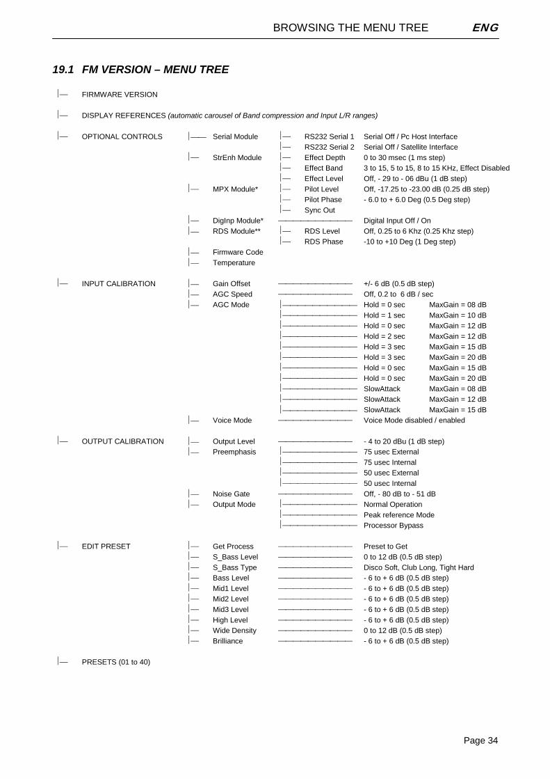
19.1 FM VERSION – MENU TREE ⏐⎯ FIRMWARE VERSION
⏐⎯ DISPLAY REFERENCES (automatic carousel of Band compression and Input L/R ranges)
⏐⎯ OPTIONAL CONTROLS ⏐⎯⎯ Serial Module ⏐⎯ RS232 Serial 1 Serial Off / Pc Host Interface ⏐⎯ RS232 Serial 2 Serial Off / Satellite Interface ⏐⎯ StrEnh Module ⏐⎯ Effect Depth 0 to 30 msec (1 ms step) ⏐⎯ Effect Band 3 to 15, 5 to 15, 8 to 15 KHz, Effect Disabled ⏐⎯ Effect Level Off, - 29 to - 06 dBu (1 dB step) ⏐⎯ MPX Module* ⏐⎯ Pilot Level Off, -17.25 to -23.00 dB (0.25 dB step) ⏐⎯ Pilot Phase - 6.0 to + 6.0 Deg (0.5 Deg step) ⏐⎯ Sync Out ⏐⎯ DigInp Module* ⎯⎯⎯⎯⎯⎯⎯⎯⎯⎯
Digital Input Off / On
⏐⎯ RDS Module** ⏐⎯ RDS Level Off, 0.25 to 6 Khz (0.25 Khz step) ⏐⎯ RDS Phase -10 to +10 Deg (1 Deg step) ⏐⎯ Firmware Code ⏐⎯ Temperature ⏐⎯ INPUT CALIBRATION ⏐⎯ Gain Offset ⎯⎯⎯⎯⎯⎯⎯⎯⎯⎯
+/- 6 dB (0.5 dB step)
⏐⎯ AGC Speed ⎯⎯⎯⎯⎯⎯⎯⎯⎯⎯
Off, 0.2 to 6 dB / sec ⏐⎯ AGC Mode ⏐⎯⎯⎯⎯⎯⎯⎯⎯⎯⎯ Hold = 0 sec MaxGain = 08 dB ⏐⎯⎯⎯⎯⎯⎯⎯⎯⎯⎯
Hold = 1 sec MaxGain = 10 dB
⏐⎯⎯⎯⎯⎯⎯⎯⎯⎯⎯
Hold = 0 sec MaxGain = 12 dB ⏐⎯⎯⎯⎯⎯⎯⎯⎯⎯⎯
Hold = 2 sec MaxGain = 12 dB
⏐⎯⎯⎯⎯⎯⎯⎯⎯⎯⎯
Hold = 3 sec MaxGain = 15 dB ⏐⎯⎯⎯⎯⎯⎯⎯⎯⎯⎯
Hold = 3 sec MaxGain = 20 dB
⏐⎯⎯⎯⎯⎯⎯⎯⎯⎯⎯
Hold = 0 sec MaxGain = 15 dB ⏐⎯⎯⎯⎯⎯⎯⎯⎯⎯⎯
Hold = 0 sec MaxGain = 20 dB
⏐⎯⎯⎯⎯⎯⎯⎯⎯⎯⎯
SlowAttack MaxGain = 08 dB ⏐⎯⎯⎯⎯⎯⎯⎯⎯⎯⎯
SlowAttack MaxGain = 12 dB
⏐⎯⎯⎯⎯⎯⎯⎯⎯⎯⎯ SlowAttack MaxGain = 15 dB ⏐⎯ Voice Mode ⎯⎯⎯⎯⎯⎯⎯⎯⎯⎯
Voice Mode disabled / enabled
⏐⎯ OUTPUT CALIBRATION ⏐⎯ Output Level ⎯⎯⎯⎯⎯⎯⎯⎯⎯⎯
- 4 to 20 dBu (1 dB step)
⏐⎯ Preemphasis ⏐⎯⎯⎯⎯⎯⎯⎯⎯⎯⎯
75 usec External ⏐⎯⎯⎯⎯⎯⎯⎯⎯⎯⎯
75 usec Internal
⏐⎯⎯⎯⎯⎯⎯⎯⎯⎯⎯
50 usec External ⏐⎯⎯⎯⎯⎯⎯⎯⎯⎯⎯
50 usec Internal
⏐⎯ Noise Gate ⎯⎯⎯⎯⎯⎯⎯⎯⎯⎯
Off, - 80 dB to - 51 dB ⏐⎯ Output Mode ⏐⎯⎯⎯⎯⎯⎯⎯⎯⎯⎯
Normal Operation
⏐⎯⎯⎯⎯⎯⎯⎯⎯⎯⎯
Peak reference Mode ⏐⎯⎯⎯⎯⎯⎯⎯⎯⎯⎯
Processor Bypass
⏐⎯ EDIT PRESET ⏐⎯ Get Process ⎯⎯⎯⎯⎯⎯⎯⎯⎯⎯
Preset to Get
⏐⎯ S_Bass Level ⎯⎯⎯⎯⎯⎯⎯⎯⎯⎯
0 to 12 dB (0.5 dB step) ⏐⎯ S_Bass Type ⎯⎯⎯⎯⎯⎯⎯⎯⎯⎯
Disco Soft, Club Long, Tight Hard
⏐⎯ Bass Level ⎯⎯⎯⎯⎯⎯⎯⎯⎯⎯
- 6 to + 6 dB (0.5 dB step) ⏐⎯ Mid1 Level ⎯⎯⎯⎯⎯⎯⎯⎯⎯⎯
- 6 to + 6 dB (0.5 dB step)
⏐⎯ Mid2 Level ⎯⎯⎯⎯⎯⎯⎯⎯⎯⎯
- 6 to + 6 dB (0.5 dB step) ⏐⎯ Mid3 Level ⎯⎯⎯⎯⎯⎯⎯⎯⎯⎯
- 6 to + 6 dB (0.5 dB step)
⏐⎯ High Level ⎯⎯⎯⎯⎯⎯⎯⎯⎯⎯
- 6 to + 6 dB (0.5 dB step) ⏐⎯ Wide Density ⎯⎯⎯⎯⎯⎯⎯⎯⎯⎯
0 to 12 dB (0.5 dB step)
⏐⎯ Brilliance ⎯⎯⎯⎯⎯⎯⎯⎯⎯⎯
- 6 to + 6 dB (0.5 dB step) ⏐⎯ PRESETS (01 to 40)
BROWSING THE MENU TREE ENG
Page 35
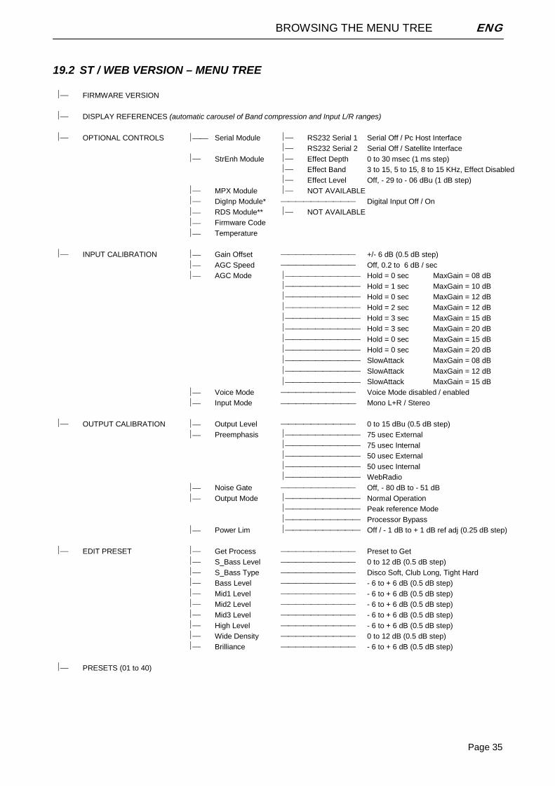
19.2 ST / WEB VERSION – MENU TREE ⏐⎯ FIRMWARE VERSION
⏐⎯ DISPLAY REFERENCES (automatic carousel of Band compression and Input L/R ranges)
⏐⎯ OPTIONAL CONTROLS ⏐⎯⎯ Serial Module ⏐⎯ RS232 Serial 1 Serial Off / Pc Host Interface ⏐⎯ RS232 Serial 2 Serial Off / Satellite Interface ⏐⎯ StrEnh Module ⏐⎯ Effect Depth 0 to 30 msec (1 ms step) ⏐⎯ Effect Band 3 to 15, 5 to 15, 8 to 15 KHz, Effect Disabled ⏐⎯ Effect Level Off, - 29 to - 06 dBu (1 dB step) ⏐⎯ MPX Module ⏐⎯ NOT AVAILABLE ⏐⎯ DigInp Module* ⎯⎯⎯⎯⎯⎯⎯⎯⎯⎯
Digital Input Off / On
⏐⎯ RDS Module** ⏐⎯ NOT AVAILABLE ⏐⎯ Firmware Code ⏐⎯ Temperature ⏐⎯ INPUT CALIBRATION ⏐⎯ Gain Offset ⎯⎯⎯⎯⎯⎯⎯⎯⎯⎯
+/- 6 dB (0.5 dB step)
⏐⎯ AGC Speed ⎯⎯⎯⎯⎯⎯⎯⎯⎯⎯
Off, 0.2 to 6 dB / sec ⏐⎯ AGC Mode ⏐⎯⎯⎯⎯⎯⎯⎯⎯⎯⎯ Hold = 0 sec MaxGain = 08 dB ⏐⎯⎯⎯⎯⎯⎯⎯⎯⎯⎯
Hold = 1 sec MaxGain = 10 dB
⏐⎯⎯⎯⎯⎯⎯⎯⎯⎯⎯
Hold = 0 sec MaxGain = 12 dB ⏐⎯⎯⎯⎯⎯⎯⎯⎯⎯⎯
Hold = 2 sec MaxGain = 12 dB
⏐⎯⎯⎯⎯⎯⎯⎯⎯⎯⎯
Hold = 3 sec MaxGain = 15 dB ⏐⎯⎯⎯⎯⎯⎯⎯⎯⎯⎯
Hold = 3 sec MaxGain = 20 dB
⏐⎯⎯⎯⎯⎯⎯⎯⎯⎯⎯
Hold = 0 sec MaxGain = 15 dB ⏐⎯⎯⎯⎯⎯⎯⎯⎯⎯⎯
Hold = 0 sec MaxGain = 20 dB
⏐⎯⎯⎯⎯⎯⎯⎯⎯⎯⎯
SlowAttack MaxGain = 08 dB ⏐⎯⎯⎯⎯⎯⎯⎯⎯⎯⎯
SlowAttack MaxGain = 12 dB
⏐⎯⎯⎯⎯⎯⎯⎯⎯⎯⎯ SlowAttack MaxGain = 15 dB ⏐⎯ Voice Mode ⎯⎯⎯⎯⎯⎯⎯⎯⎯⎯
Voice Mode disabled / enabled
⏐⎯ Input Mode ⎯⎯⎯⎯⎯⎯⎯⎯⎯⎯ Mono L+R / Stereo ⏐⎯ OUTPUT CALIBRATION ⏐⎯ Output Level ⎯⎯⎯⎯⎯⎯⎯⎯⎯⎯
0 to 15 dBu (0.5 dB step)
⏐⎯ Preemphasis ⏐⎯⎯⎯⎯⎯⎯⎯⎯⎯⎯
75 usec External ⏐⎯⎯⎯⎯⎯⎯⎯⎯⎯⎯
75 usec Internal
⏐⎯⎯⎯⎯⎯⎯⎯⎯⎯⎯
50 usec External ⏐⎯⎯⎯⎯⎯⎯⎯⎯⎯⎯
50 usec Internal
⏐⎯⎯⎯⎯⎯⎯⎯⎯⎯⎯
WebRadio ⏐⎯ Noise Gate ⎯⎯⎯⎯⎯⎯⎯⎯⎯⎯
Off, - 80 dB to - 51 dB
⏐⎯ Output Mode ⏐⎯⎯⎯⎯⎯⎯⎯⎯⎯⎯
Normal Operation ⏐⎯⎯⎯⎯⎯⎯⎯⎯⎯⎯
Peak reference Mode
⏐⎯⎯⎯⎯⎯⎯⎯⎯⎯⎯
Processor Bypass ⏐⎯ Power Lim ⏐⎯⎯⎯⎯⎯⎯⎯⎯⎯⎯
Off / - 1 dB to + 1 dB ref adj (0.25 dB step)
⏐⎯ EDIT PRESET ⏐⎯ Get Process ⎯⎯⎯⎯⎯⎯⎯⎯⎯⎯
Preset to Get
⏐⎯ S_Bass Level ⎯⎯⎯⎯⎯⎯⎯⎯⎯⎯
0 to 12 dB (0.5 dB step) ⏐⎯ S_Bass Type ⎯⎯⎯⎯⎯⎯⎯⎯⎯⎯
Disco Soft, Club Long, Tight Hard
⏐⎯ Bass Level ⎯⎯⎯⎯⎯⎯⎯⎯⎯⎯
- 6 to + 6 dB (0.5 dB step) ⏐⎯ Mid1 Level ⎯⎯⎯⎯⎯⎯⎯⎯⎯⎯
- 6 to + 6 dB (0.5 dB step)
⏐⎯ Mid2 Level ⎯⎯⎯⎯⎯⎯⎯⎯⎯⎯
- 6 to + 6 dB (0.5 dB step) ⏐⎯ Mid3 Level ⎯⎯⎯⎯⎯⎯⎯⎯⎯⎯
- 6 to + 6 dB (0.5 dB step)
⏐⎯ High Level ⎯⎯⎯⎯⎯⎯⎯⎯⎯⎯
- 6 to + 6 dB (0.5 dB step) ⏐⎯ Wide Density ⎯⎯⎯⎯⎯⎯⎯⎯⎯⎯
0 to 12 dB (0.5 dB step)
⏐⎯ Brilliance ⎯⎯⎯⎯⎯⎯⎯⎯⎯⎯
- 6 to + 6 dB (0.5 dB step) ⏐⎯ PRESETS (01 to 40)
BROWSING THE MENU TREE ENG
Page 36
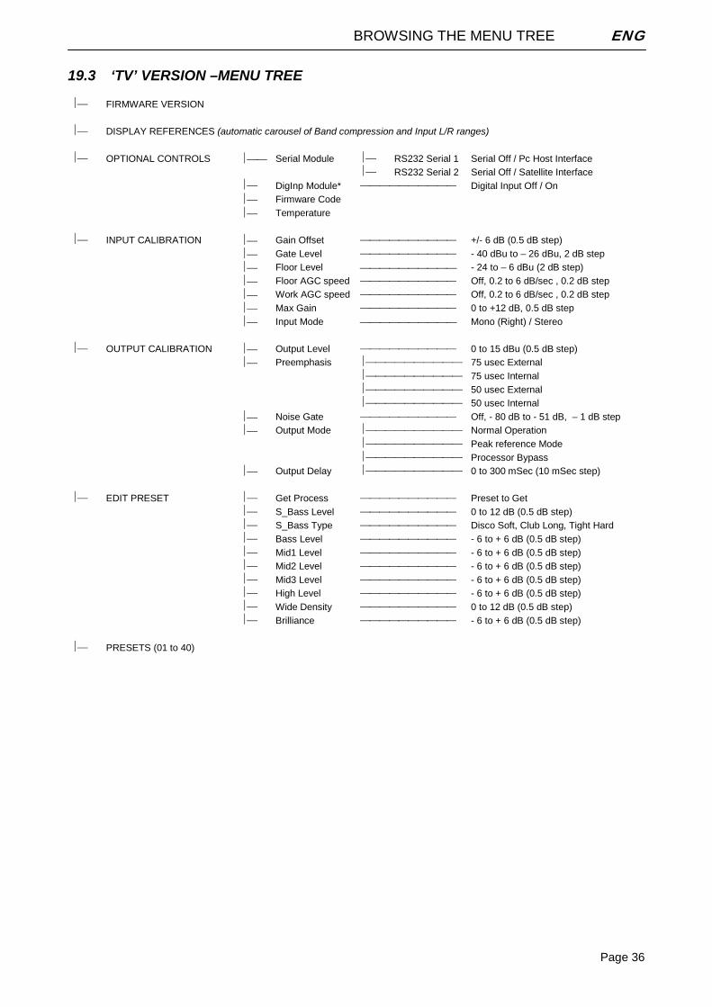
19.3 ‘TV’ VERSION –MENU TREE ⏐⎯ FIRMWARE VERSION
⏐⎯ DISPLAY REFERENCES (automatic carousel of Band compression and Input L/R ranges)
⏐⎯ OPTIONAL CONTROLS ⏐⎯⎯ Serial Module ⏐⎯ RS232 Serial 1 Serial Off / Pc Host Interface ⏐⎯ RS232 Serial 2 Serial Off / Satellite Interface ⏐⎯ DigInp Module* ⎯⎯⎯⎯⎯⎯⎯⎯⎯⎯
Digital Input Off / On
⏐⎯ Firmware Code ⏐⎯ Temperature ⏐⎯ INPUT CALIBRATION ⏐⎯ Gain Offset ⎯⎯⎯⎯⎯⎯⎯⎯⎯⎯
+/- 6 dB (0.5 dB step)
⏐⎯ Gate Level ⎯⎯⎯⎯⎯⎯⎯⎯⎯⎯
- 40 dBu to – 26 dBu, 2 dB step ⏐⎯ Floor Level ⎯⎯⎯⎯⎯⎯⎯⎯⎯⎯ - 24 to – 6 dBu (2 dB step) ⏐⎯ Floor AGC speed ⎯⎯⎯⎯⎯⎯⎯⎯⎯⎯
Off, 0.2 to 6 dB/sec , 0.2 dB step
⏐⎯ Work AGC speed ⎯⎯⎯⎯⎯⎯⎯⎯⎯⎯
Off, 0.2 to 6 dB/sec , 0.2 dB step ⏐⎯ Max Gain ⎯⎯⎯⎯⎯⎯⎯⎯⎯⎯
0 to +12 dB, 0.5 dB step
⏐⎯ Input Mode ⎯⎯⎯⎯⎯⎯⎯⎯⎯⎯ Mono (Right) / Stereo ⏐⎯ OUTPUT CALIBRATION ⏐⎯ Output Level ⎯⎯⎯⎯⎯⎯⎯⎯⎯⎯
0 to 15 dBu (0.5 dB step)
⏐⎯ Preemphasis ⏐⎯⎯⎯⎯⎯⎯⎯⎯⎯⎯
75 usec External ⏐⎯⎯⎯⎯⎯⎯⎯⎯⎯⎯
75 usec Internal
⏐⎯⎯⎯⎯⎯⎯⎯⎯⎯⎯
50 usec External ⏐⎯⎯⎯⎯⎯⎯⎯⎯⎯⎯
50 usec Internal
⏐⎯ Noise Gate ⎯⎯⎯⎯⎯⎯⎯⎯⎯⎯
Off, - 80 dB to - 51 dB, – 1 dB step ⏐⎯ Output Mode ⏐⎯⎯⎯⎯⎯⎯⎯⎯⎯⎯
Normal Operation
⏐⎯⎯⎯⎯⎯⎯⎯⎯⎯⎯
Peak reference Mode ⏐⎯⎯⎯⎯⎯⎯⎯⎯⎯⎯
Processor Bypass
⏐⎯ Output Delay ⏐⎯⎯⎯⎯⎯⎯⎯⎯⎯⎯
0 to 300 mSec (10 mSec step) ⏐⎯ EDIT PRESET ⏐⎯ Get Process ⎯⎯⎯⎯⎯⎯⎯⎯⎯⎯
Preset to Get
⏐⎯ S_Bass Level ⎯⎯⎯⎯⎯⎯⎯⎯⎯⎯
0 to 12 dB (0.5 dB step) ⏐⎯ S_Bass Type ⎯⎯⎯⎯⎯⎯⎯⎯⎯⎯
Disco Soft, Club Long, Tight Hard
⏐⎯ Bass Level ⎯⎯⎯⎯⎯⎯⎯⎯⎯⎯
- 6 to + 6 dB (0.5 dB step) ⏐⎯ Mid1 Level ⎯⎯⎯⎯⎯⎯⎯⎯⎯⎯
- 6 to + 6 dB (0.5 dB step)
⏐⎯ Mid2 Level ⎯⎯⎯⎯⎯⎯⎯⎯⎯⎯
- 6 to + 6 dB (0.5 dB step) ⏐⎯ Mid3 Level ⎯⎯⎯⎯⎯⎯⎯⎯⎯⎯
- 6 to + 6 dB (0.5 dB step)
⏐⎯ High Level ⎯⎯⎯⎯⎯⎯⎯⎯⎯⎯
- 6 to + 6 dB (0.5 dB step) ⏐⎯ Wide Density ⎯⎯⎯⎯⎯⎯⎯⎯⎯⎯
0 to 12 dB (0.5 dB step)
⏐⎯ Brilliance ⎯⎯⎯⎯⎯⎯⎯⎯⎯⎯
- 6 to + 6 dB (0.5 dB step) ⏐⎯ PRESETS (01 to 40)
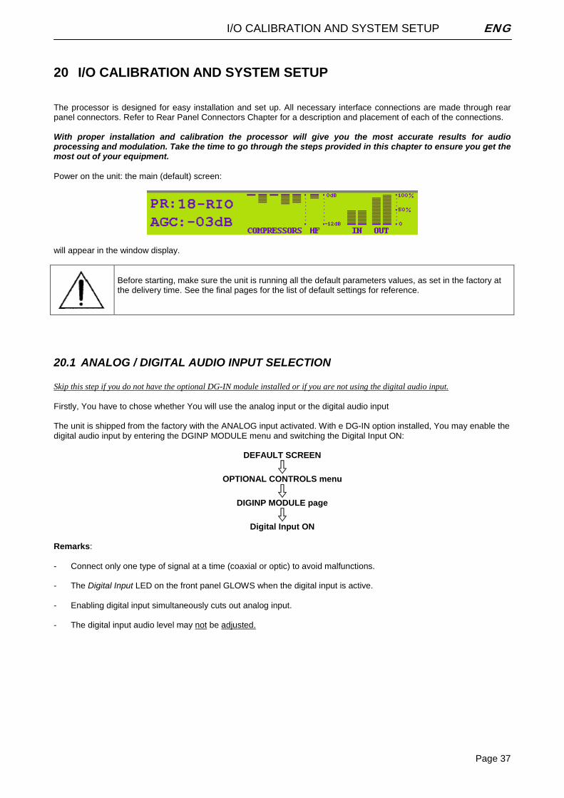
I/O CALIBRATION AND SYSTEM SETUP ENG
Page 37
20 I/O CALIBRATION AND SYSTEM SETUP The processor is designed for easy installation and set up. All necessary interface connections are made through rear panel connectors. Refer to Rear Panel Connectors Chapter for a description and placement of each of the connections. With proper installation and calibration the processor will give you the most accurate results for audio processing and modulation. Take the time to go through the steps provided in this chapter to ensure you get the most out of your equipment. Power on the unit: the main (default) screen:
will appear in the window display.
Before starting, make sure the unit is running all the default parameters values, as set in the factory at the delivery time. See the final pages for the list of default settings for reference.
20.1 ANALOG / DIGITAL AUDIO INPUT SELECTION Skip this step if you do not have the optional DG-IN module installed or if you are not using the digital audio input. Firstly, You have to chose whether You will use the analog input or the digital audio input The unit is shipped from the factory with the ANALOG input activated. With e DG-IN option installed, You may enable the digital audio input by entering the DGINP MODULE menu and switching the Digital Input ON:
DEFAULT SCREEN
OPTIONAL CONTROLS menu
DIGINP MODULE page
Digital Input ON Remarks: - Connect only one type of signal at a time (coaxial or optic) to avoid malfunctions. - The Digital Input LED on the front panel GLOWS when the digital input is active. - Enabling digital input simultaneously cuts out analog input. - The digital input audio level may not be adjusted.
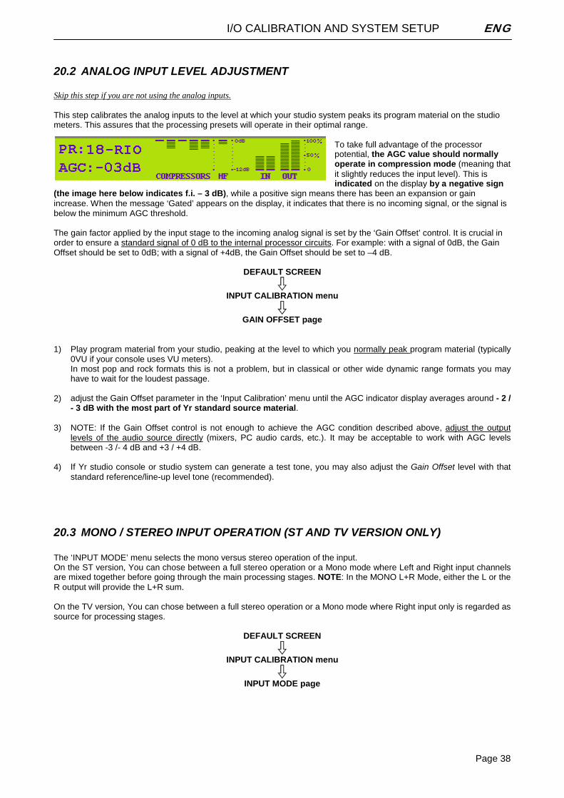
I/O CALIBRATION AND SYSTEM SETUP ENG
Page 38
20.2 ANALOG INPUT LEVEL ADJUSTMENT Skip this step if you are not using the analog inputs. This step calibrates the analog inputs to the level at which your studio system peaks its program material on the studio meters. This assures that the processing presets will operate in their optimal range.
To take full advantage of the processor potential, the AGC value should normally operate in compression mode (meaning that it slightly reduces the input level). This is indicated on the display by a negative sign
(the image here below indicates f.i. – 3 dB), while a positive sign means there has been an expansion or gain increase. When the message ‘Gated’ appears on the display, it indicates that there is no incoming signal, or the signal is below the minimum AGC threshold. The gain factor applied by the input stage to the incoming analog signal is set by the ‘Gain Offset’ control. It is crucial in order to ensure a standard signal of 0 dB to the internal processor circuits. For example: with a signal of 0dB, the Gain Offset should be set to 0dB; with a signal of +4dB, the Gain Offset should be set to –4 dB.
DEFAULT SCREEN
INPUT CALIBRATION menu
GAIN OFFSET page 1) Play program material from your studio, peaking at the level to which you normally peak program material (typically
0VU if your console uses VU meters). In most pop and rock formats this is not a problem, but in classical or other wide dynamic range formats you may have to wait for the loudest passage.
2) adjust the Gain Offset parameter in the ‘Input Calibration’ menu until the AGC indicator display averages around - 2 / - 3 dB with the most part of Yr standard source material.
3) NOTE: If the Gain Offset control is not enough to achieve the AGC condition described above, adjust the output levels of the audio source directly (mixers, PC audio cards, etc.). It may be acceptable to work with AGC levels between -3 /- 4 dB and +3 / +4 dB.
4) If Yr studio console or studio system can generate a test tone, you may also adjust the Gain Offset level with that standard reference/line-up level tone (recommended).
20.3 MONO / STEREO INPUT OPERATION (ST AND TV VERSION ONLY) The ‘INPUT MODE’ menu selects the mono versus stereo operation of the input. On the ST version, You can chose between a full stereo operation or a Mono mode where Left and Right input channels are mixed together before going through the main processing stages. NOTE: In the MONO L+R Mode, either the L or the R output will provide the L+R sum. On the TV version, You can chose between a full stereo operation or a Mono mode where Right input only is regarded as source for processing stages.
DEFAULT SCREEN
INPUT CALIBRATION menu
INPUT MODE page
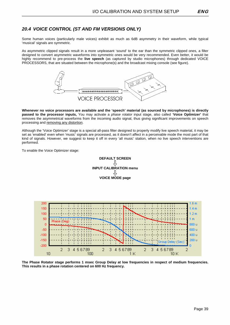
I/O CALIBRATION AND SYSTEM SETUP ENG
Page 39
20.4 VOICE CONTROL (ST AND FM VERSIONS ONLY) Some human voices (particularly male voices) exhibit as much as 6dB asymmetry in their waveform, while typical ‘musical’ signals are symmetric. As asymmetric clipped signals result in a more unpleasant ‘sound’ to the ear than the symmetric clipped ones, a filter designed to convert asymmetric waveforms into symmetric ones would be very recommended. Even better, it would be highly recommend to pre-process the live speech (as captured by studio microphones) through dedicated VOICE PROCESSORS, that are situated between the microphone(s) and the broadcast mixing console (see figure).
Whenever no voice processors are available and the ‘speech’ material (as sourced by microphones) is directly passed to the processor inputs, You may activate a phase rotator input stage, also called ‘Voice Optimizer’ that removes the asymmetrical waveforms from the incoming audio signal, thus giving significant improvements on speech processing and removing any distortion. Although the ‘Voice Optimizer’ stage is a special all-pass filter designed to properly modify live speech material, it may be set as ‘enabled’ even when ‘music’ signals are processed, as it doesn’t affect in a perceivable mode the most part of that kind of signals. However, we suggest to keep it off in every ‘all music’ station, when no live speech interventions are performed. To enable the Voice Optimizer stage:
DEFAULT SCREEN
INPUT CALIBRATION menu
VOICE MODE page
The Phase Rotator stage performs 1 msec Group Delay at low frequencies in respect of medium frequencies. This results in a phase rotation centered on 600 Hz frequency.
AGC CALIBRATION AND SETUP (FM and ST / WEB versions) ENG
Page 40
21 AGC CALIBRATION AND SETUP (FM and ST / WEB versions)
21.1 AGC SPEED One of the most important processor function is the Automatic Gain Control (AGC) system, which compensates for variations in the input level to keep the signal at 0 dB. The following parameters regulate the AGC function and may be modified:
0 AGC Speed: sets the signal compensation speed 1 AGC Mode: sets the maximum amplification level (MaxG), correction pause time (Hold) and the freeze
threshold (GATE)
DEFAULT SCREEN
INPUT CALIBRATION menu
AGC Speed The AGC speed value is expressed in dB/sec - i.e. the number of dB amplified or attenuated in one second. The AGC operates at its full speed value only when the input signal level is less than - 3dB and greater than 3 dB compared to the internal 0 dB reference level. Within this interval, the AGC speed is reduced to one quarter of the set value, as high compression and high amplification speed on the whole band can engender unpleasant pumping effects. For example, with AGC speed = + 5 dB, an input signal of - 15 dBm will be amplified to - 5 dBm in exactly two seconds (the approach to the 0 threshold is slower, as explained). High AGC Speed values obviously make it possible to quickly recover strong level differences, but they can also lead to unpleasant ‘pumping’ effects. We suggest using medium speed levels of around 2 to 3 dB, and especially that you concentrate on the audio sources connected to the processor, to obtain the most even sound possible. AGC Speed acts on both the digital and analog inputs and sets the compensation speed of the input channel signal level variation.
21.2 AGC MODE The AGC Mode menu mainly serves to regulate the maximum level gain recoverable by the AGC (MaxGain) and its intervention time (with reference to the interval –3 to 3 dB within which the AGC works at one quarter of the user-set speed).
DEFAULT SCREEN
INPUT CALIBRATION menu
AGC Mode The Hold parameter allows you to define the time the AGC system has to wait before intervening when the signal varies. Hold = 0 means that the system reacts instantly to any source signal variations, while Hold = 2 means that you must wait two seconds before the automatic level compensation process begins. F.i., if AGC Speed is set as 2 dB/sec and the input signal drops down of 6 dB, the compensation trip will be completely reached after 3 seconds if Hold time is 0 sec (6/2) and after 6 seconds (3 + 6/2) if Hold time is 3 seconds.
AGC CALIBRATION AND SETUP (FM and ST / WEB versions) ENG
Page 41
For best performance, we recommend using Hold = 0Sec (Mode 2) for musical sources and Hold = 3 Sec (Mode 5) for ‘speech’ sources. The MaxG (Maximum Gain) parameter sets the maximum amplification value attainable by the AGC system. For instance, setting Mode 2 means that maximum amplification is +12dB: thus a –12dB signal can be compensated to 0, while a –15dB signal will reach a maximum of –3dB. We suggest setting a medium MaxGain value (no more than +12 dB, keeping in mind that this value may already be enough to alter level ratios between different musical passages, as in the case of classical music), and Hold= 0 if the music flow is discontinuous and immediate AGC intervention is required, or a higher Hold value (3 or 4 seconds) if any silent breaks may occur during the broadcast (pauses in speech, line changeover between studios, etc.). The Gate parameter indicates the threshold level under which the AGC system is frozen, and does not amplify the signal. While operating without the signal, the display visualizes the AGC GATE status. Once you have located this feature in the Input Calibration submenu, use the shuttle to select one of the following 5 fixed combinations (NOTE: the above parameters may not be selected or edited individually, but only within the preset combinations):
- Mode 0 Hold=0Sec MaxG=+08dB Gate=-18dB - Mode 1 Hold=1Sec MaxG=+10dB Gate=-18dB - Mode 2 Hold=0Sec MaxG=+12dB Gate=-18dB - Mode 3 Hold=2Sec MaxG=+12dB Gate=-24dB - Mode 4 Hold=3Sec MaxG=+15dB Gate=-24dB - Mode 5 Hold=3Sec MaxG=+20dB Gate=-24dB - Mode 6 Hold=0Sec MaxG=+15dB Gate=-24dB - Mode 7 Hold=0Sec MaxG=+20dB Gate=-24dB - Mode 8 SlowAttack MaxG=+08dB - Mode 9 SlowAttack MaxG=+12dB - Mode10 SlowAttack MaxG=+15dB
The AGC Mode = Slow Attack option is recommended wherever audio source are affected by high-speed and unexpected level modifications (f.i. voice or music not pre-processed) which might generate ‘pumping’ effect in the broadcast signal. What about MaxGain parameter, see par. 5.10. Recommended setting value: MaxGain = 12 dB. NOTE: Gate parameter is not displayed on the processor LCD panel.
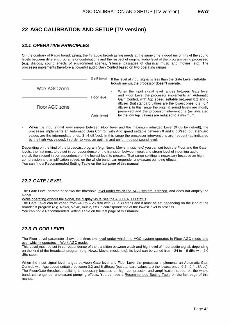
AGC CALIBRATION AND SETUP (TV version) ENG
Page 42
22 AGC CALIBRATION AND SETUP (TV version)
22.1 OPERATIVE PRINCIPLES On the contrary of Radio broadcasting, the Tv audio broadcasting needs at the same time a good uniformity of the sound levels between different programs or contributions and the respect of original audio level of the program being processed (e.g. dialogs, sound effects of environment scenes, ‘silence’ passages of classical music and movies, etc). The processor implements therefore a powerful audio Gain Control based on two operating ranges :
If the level of input signal is less than the Gate Level (settable trough menu), the processor doesn’t operate. - When the input signal level ranges between Gate level
and Floor Level the processor implements an Automatic Gain Control, with Agc speed settable between 0.2 and 6 dB/sec (but standard values are the lowest ones: 0.2 ; 0.4 dB/sec). In this range the original sound levels are mostly preserved and the processor interventions (as indicated by the low Agc values) are reduced to a minimum.
- When the input signal level ranges between Floor level and the maximum admitted Level (0 dB by default), the
processor implements an Automatic Gain Control, with Agc speed settable between 0 and 6 dB/sec (but standard values are the intermediate ones: 3 ÷4 dB/sec). In this range the processor interventions are frequent (as indicated by the high Agc values), in order to keep an optimal and uniform output sound level.
Depending on the kind of the broadcast program (e.g. News, Movie, music, etc) you can set both the Floor and the Gate levels: the first must to be set in correspondence of the transition between weak and strong level of incoming audio signal; the second in correspondence of the lowest level to process. That range splitting is necessary because an high compression and amplification speed, on the whole band, can engender unpleasant pumping effects. You can find a Recommended Setting Table on the last page of this manual.
22.2 GATE LEVEL The Gate Level parameter shows the threshold level under which the AGC system is frozen, and does not amplify the signal. While operating without the signal, the display visualises the AGC GATED status. The Gate Level can be varied from –40 to – 26 dBu with 2.0 dBu steps and it must be set depending on the kind of the broadcast program (e.g. News, Movie, music, etc) in correspondence of the lowest level to process. You can find a Recommended Setting Table on the last page of this manual.
22.3 FLOOR LEVEL The Floor Level parameter shows the threshold level under which the AGC system operates in Floor AGC mode and over which it operates in Work AGC mode. This Level must be set in correspondence of the transition between weak and high level of input audio signal, depending on the kind of the broadcast program (e.g. News, Movie, music, etc). Its level can be varied from –24 to – 6 dBu with 2.0 dBu steps. When the input signal level ranges between Gate level and Floor Level the processor implements an Automatic Gain Control, with Agc speed settable between 0.2 and 6 dB/sec (but standard values are the lowest ones: 0.2 ; 0.4 dB/sec). The Floor/Gate thresholds splitting is necessary because an high compression and amplification speed, on the whole band, can engender unpleasant pumping effects. You can see a Recommended Setting Table on the last page of this manual.
AGC CALIBRATION AND SETUP (TV version) ENG
Page 43
22.4 FLOOR AGC Floor AGC acts both on the digital and analogue inputs and set the compensation speed of the input signal level variation when its level ranges between Gate and Floor thresholds. In this range the original sound levels are mostly preserved and the processor interventions (as indicated by the low Agc values) are reduced to a minimum. The Floor AGC speed value is expressed in dB/sec (the number of dB amplified or attenuated in 1 sec) and can be varied from 0 (Off state) to +6.0 dB/sec with 0.2 dB/sec step. You can find a Recommended Setting Table on the current page of this manual.
22.5 WORK AGC Work AGC acts both on the digital and analogue inputs and set the compensation speed of the input channel signal level variation when its level ranges between the Floor and the maximum admitted Level (0 dB by default * ). In this range the processor interventions are frequent (as indicated by the high Agc values), in order to keep an optimal and uniform output sound level. The Work AGC speed value is expressed in dB/sec (the number of dB amplified or attenuated in 1 sec) and can be varied from 0 (Off state) to +6.0 dB/sec with 0.2 dB/sec step. You can find a Recommended Setting Table on the current page of this manual.
22.6 MAX GAIN The MaxG parameter (Maximum Gain) set the maximum amplification value which can be reached by the AGC system. The parameter can be varied from 0 to + 12 dB in 0.5 dB steps. You can find a Recommended Setting Table on the last page of this manual.
22.7 DEFAULT VALUES FOR AGC – TV VERSION NOTA: factory preseti are related to ‘General Purpose’ profile
MENU SUB MENU VOCE VALORE Gain Offset AGC Offset Control + 0.0 dB ** Gate Level AGC Gate Level GenPurpose
Movie News
-30 dBu -28 dBu -35 dBu
Floor Level Floor Zone Level GenPurpose Movie News
-16 dBu -10 dBu -16 dBu
Floor Agc Floor AGC Speed GenPurpose Movie News
0.2 dB/sec 0.4 dB/sec 0.4 dB/sec
Work Agc Work AGC Speed GenPurpose Movie News
3 dB/sec 3 dB/sec 2.5 dB/sec
Input Calibration
Max Gain Max AGC Gain GenPurpose Movie News
6 dB 4 dB 4 dB
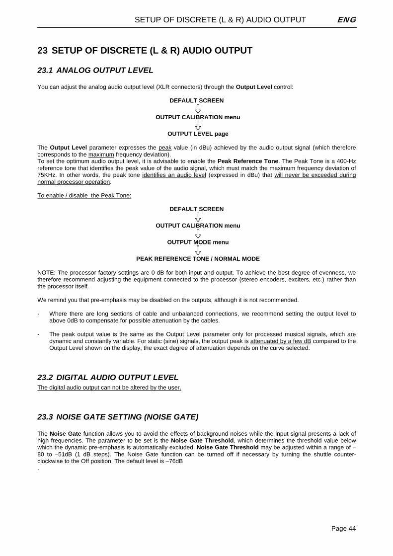
SETUP OF DISCRETE (L & R) AUDIO OUTPUT ENG
Page 44
23 SETUP OF DISCRETE (L & R) AUDIO OUTPUT
23.1 ANALOG OUTPUT LEVEL You can adjust the analog audio output level (XLR connectors) through the Output Level control:
DEFAULT SCREEN
OUTPUT CALIBRATION menu
OUTPUT LEVEL page The Output Level parameter expresses the peak value (in dBu) achieved by the audio output signal (which therefore corresponds to the maximum frequency deviation). To set the optimum audio output level, it is advisable to enable the Peak Reference Tone. The Peak Tone is a 400-Hz reference tone that identifies the peak value of the audio signal, which must match the maximum frequency deviation of 75KHz. In other words, the peak tone identifies an audio level (expressed in dBu) that will never be exceeded during normal processor operation. To enable / disable the Peak Tone:
DEFAULT SCREEN
OUTPUT CALIBRATION menu
OUTPUT MODE menu
PEAK REFERENCE TONE / NORMAL MODE NOTE: The processor factory settings are 0 dB for both input and output. To achieve the best degree of evenness, we therefore recommend adjusting the equipment connected to the processor (stereo encoders, exciters, etc.) rather than the processor itself. We remind you that pre-emphasis may be disabled on the outputs, although it is not recommended. - Where there are long sections of cable and unbalanced connections, we recommend setting the output level to
above 0dB to compensate for possible attenuation by the cables. - The peak output value is the same as the Output Level parameter only for processed musical signals, which are
dynamic and constantly variable. For static (sine) signals, the output peak is attenuated by a few dB compared to the Output Level shown on the display; the exact degree of attenuation depends on the curve selected.
23.2 DIGITAL AUDIO OUTPUT LEVEL The digital audio output can not be altered by the user.
23.3 NOISE GATE SETTING (NOISE GATE) The Noise Gate function allows you to avoid the effects of background noises while the input signal presents a lack of high frequencies. The parameter to be set is the Noise Gate Threshold, which determines the threshold value below which the dynamic pre-emphasis is automatically excluded. Noise Gate Threshold may be adjusted within a range of –80 to –51dB (1 dB steps). The Noise Gate function can be turned off if necessary by turning the shuttle counter-clockwise to the Off position. The default level is –76dB .
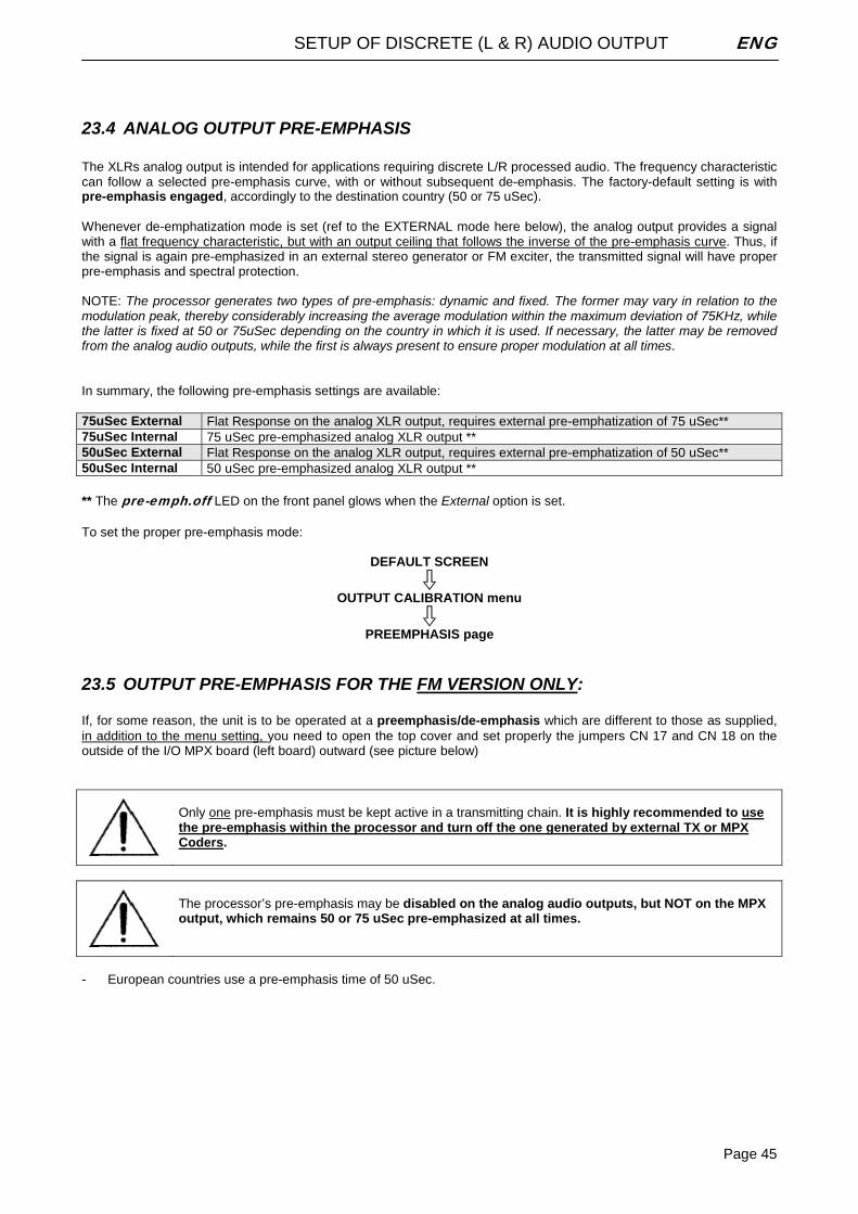
SETUP OF DISCRETE (L & R) AUDIO OUTPUT ENG
Page 45
23.4 ANALOG OUTPUT PRE-EMPHASIS The XLRs analog output is intended for applications requiring discrete L/R processed audio. The frequency characteristic can follow a selected pre-emphasis curve, with or without subsequent de-emphasis. The factory-default setting is with pre-emphasis engaged, accordingly to the destination country (50 or 75 uSec). Whenever de-emphatization mode is set (ref to the EXTERNAL mode here below), the analog output provides a signal with a flat frequency characteristic, but with an output ceiling that follows the inverse of the pre-emphasis curve. Thus, if the signal is again pre-emphasized in an external stereo generator or FM exciter, the transmitted signal will have proper pre-emphasis and spectral protection. NOTE: The processor generates two types of pre-emphasis: dynamic and fixed. The former may vary in relation to the modulation peak, thereby considerably increasing the average modulation within the maximum deviation of 75KHz, while the latter is fixed at 50 or 75uSec depending on the country in which it is used. If necessary, the latter may be removed from the analog audio outputs, while the first is always present to ensure proper modulation at all times. In summary, the following pre-emphasis settings are available: 75uSec External Flat Response on the analog XLR output, requires external pre-emphatization of 75 uSec** 75uSec Internal 75 uSec pre-emphasized analog XLR output ** 50uSec External Flat Response on the analog XLR output, requires external pre-emphatization of 50 uSec** 50uSec Internal 50 uSec pre-emphasized analog XLR output ** ** The pre-emph.off LED on the front panel glows when the External option is set. To set the proper pre-emphasis mode:
DEFAULT SCREEN
OUTPUT CALIBRATION menu
PREEMPHASIS page
23.5 OUTPUT PRE-EMPHASIS FOR THE FM VERSION ONLY: If, for some reason, the unit is to be operated at a preemphasis/de-emphasis which are different to those as supplied, in addition to the menu setting, you need to open the top cover and set properly the jumpers CN 17 and CN 18 on the outside of the I/O MPX board (left board) outward (see picture below)
Only one pre-emphasis must be kept active in a transmitting chain. It is highly recommended to use the pre-emphasis within the processor and turn off the one generated by external TX or MPX Coders.
The processor’s pre-emphasis may be disabled on the analog audio outputs, but NOT on the MPX output, which remains 50 or 75 uSec pre-emphasized at all times.
- European countries use a pre-emphasis time of 50 uSec.
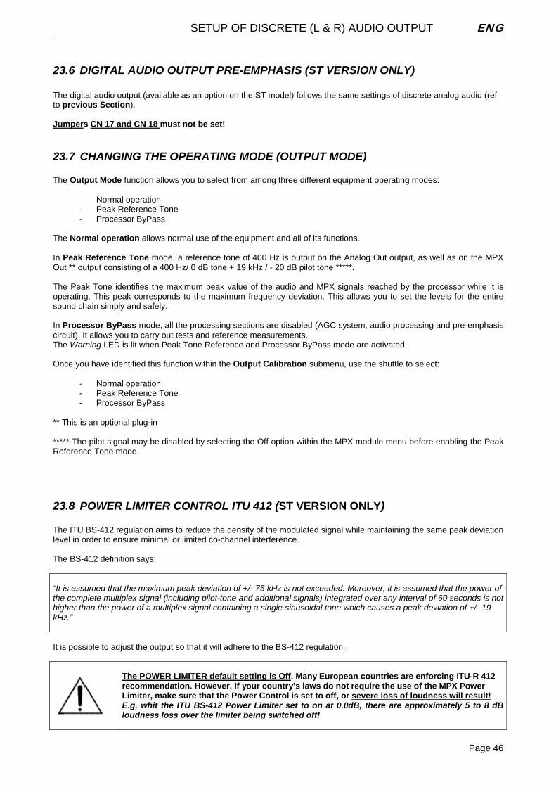
SETUP OF DISCRETE (L & R) AUDIO OUTPUT ENG
Page 46
23.6 DIGITAL AUDIO OUTPUT PRE-EMPHASIS (ST VERSION ONLY) The digital audio output (available as an option on the ST model) follows the same settings of discrete analog audio (ref to previous Section). Jumpers CN 17 and CN 18 must not be set!
23.7 CHANGING THE OPERATING MODE (OUTPUT MODE) The Output Mode function allows you to select from among three different equipment operating modes:
- Normal operation - Peak Reference Tone - Processor ByPass
The Normal operation allows normal use of the equipment and all of its functions. In Peak Reference Tone mode, a reference tone of 400 Hz is output on the Analog Out output, as well as on the MPX Out ** output consisting of a 400 Hz/ 0 dB tone + 19 kHz / - 20 dB pilot tone *****. The Peak Tone identifies the maximum peak value of the audio and MPX signals reached by the processor while it is operating. This peak corresponds to the maximum frequency deviation. This allows you to set the levels for the entire sound chain simply and safely. In Processor ByPass mode, all the processing sections are disabled (AGC system, audio processing and pre-emphasis circuit). It allows you to carry out tests and reference measurements. The Warning LED is lit when Peak Tone Reference and Processor ByPass mode are activated. Once you have identified this function within the Output Calibration submenu, use the shuttle to select:
- Normal operation - Peak Reference Tone - Processor ByPass
** This is an optional plug-in ***** The pilot signal may be disabled by selecting the Off option within the MPX module menu before enabling the Peak Reference Tone mode.
23.8 POWER LIMITER CONTROL ITU 412 (ST VERSION ONLY) The ITU BS-412 regulation aims to reduce the density of the modulated signal while maintaining the same peak deviation level in order to ensure minimal or limited co-channel interference. The BS-412 definition says: “It is assumed that the maximum peak deviation of +/- 75 kHz is not exceeded. Moreover, it is assumed that the power of the complete multiplex signal (including pilot-tone and additional signals) integrated over any interval of 60 seconds is not higher than the power of a multiplex signal containing a single sinusoidal tone which causes a peak deviation of +/- 19 kHz.” It is possible to adjust the output so that it will adhere to the BS-412 regulation.
The POWER LIMITER default setting is Off. Many European countries are enforcing ITU-R 412 recommendation. However, if your country’s laws do not require the use of the MPX Power Limiter, make sure that the Power Control is set to off, or severe loss of loudness will result! E.g, whit the ITU BS-412 Power Limiter set to on at 0.0dB, there are approximately 5 to 8 dB loudness loss over the limiter being switched off!
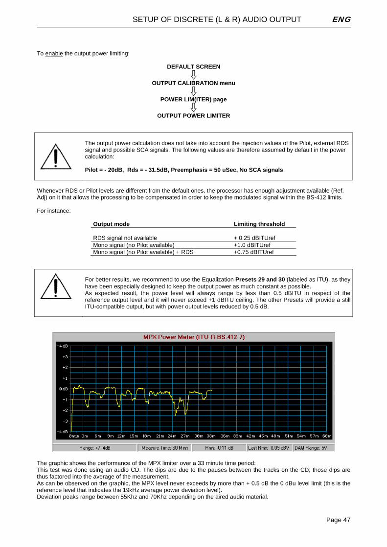
SETUP OF DISCRETE (L & R) AUDIO OUTPUT ENG
Page 47
To enable the output power limiting:
DEFAULT SCREEN
OUTPUT CALIBRATION menu
POWER LIM(ITER) page
OUTPUT POWER LIMITER
The output power calculation does not take into account the injection values of the Pilot, external RDS signal and possible SCA signals. The following values are therefore assumed by default in the power calculation: Pilot = - 20dB, Rds = - 31.5dB, Preemphasis = 50 uSec, No SCA signals
Whenever RDS or Pilot levels are different from the default ones, the processor has enough adjustment available (Ref. Adj) on it that allows the processing to be compensated in order to keep the modulated signal within the BS-412 limits. For instance:
Output mode Limiting threshold RDS signal not available + 0.25 dBITUref Mono signal (no Pilot available) +1.0 dBITUref Mono signal (no Pilot available) + RDS +0.75 dBITUref
For better results, we recommend to use the Equalization Presets 29 and 30 (labeled as ITU), as they have been especially designed to keep the output power as much constant as possible. As expected result, the power level will always range by less than 0.5 dBITU in respect of the reference output level and it will never exceed +1 dBITU ceiling. The other Presets will provide a still ITU-compatible output, but with power output levels reduced by 0.5 dB.
The graphic shows the performance of the MPX limiter over a 33 minute time period: This test was done using an audio CD. The dips are due to the pauses between the tracks on the CD; those dips are thus factored into the average of the measurement. As can be observed on the graphic, the MPX level never exceeds by more than + 0.5 dB the 0 dBu level limit (this is the reference level that indicates the 19kHz average power deviation level). Deviation peaks range between 55Khz and 70Khz depending on the aired audio material.
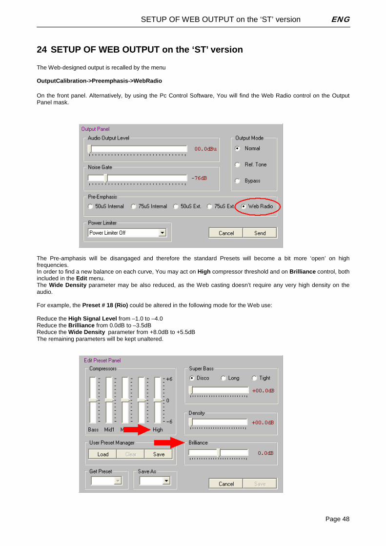
SETUP OF WEB OUTPUT on the ‘ST’ version ENG
Page 48
24 SETUP OF WEB OUTPUT on the ‘ST’ version The Web-designed output is recalled by the menu OutputCalibration->Preemphasis->WebRadio On the front panel. Alternatively, by using the Pc Control Software, You will find the Web Radio control on the Output Panel mask.
The Pre-amphasis will be disangaged and therefore the standard Presets will become a bit more ‘open’ on high frequencies. In order to find a new balance on each curve, You may act on High compressor threshold and on Brilliance control, both included in the Edit menu. The Wide Density parameter may be also reduced, as the Web casting doesn’t require any very high density on the audio. For example, the Preset # 18 (Rio) could be altered in the following mode for the Web use: Reduce the High Signal Level from –1.0 to –4.0 Reduce the Brilliance from 0.0dB to –3.5dB Reduce the Wide Density parameter from +8.0dB to +5.5dB The remaining parameters will be kept unaltered.
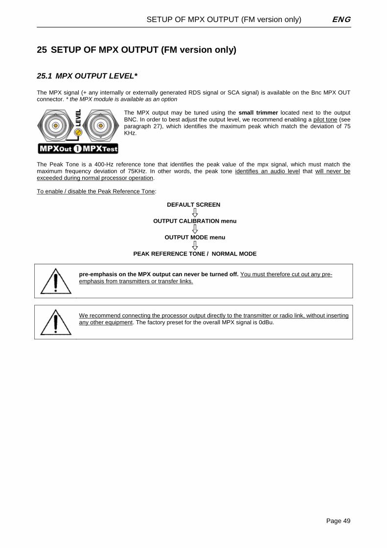
SETUP OF MPX OUTPUT (FM version only) ENG
Page 49
25 SETUP OF MPX OUTPUT (FM version only)
25.1 MPX OUTPUT LEVEL* The MPX signal (+ any internally or externally generated RDS signal or SCA signal) is available on the Bnc MPX OUT connector. * the MPX module is available as an option
The MPX output may be tuned using the small trimmer located next to the output BNC. In order to best adjust the output level, we recommend enabling a pilot tone (see paragraph 27), which identifies the maximum peak which match the deviation of 75 KHz.
The Peak Tone is a 400-Hz reference tone that identifies the peak value of the mpx signal, which must match the maximum frequency deviation of 75KHz. In other words, the peak tone identifies an audio level that will never be exceeded during normal processor operation. To enable / disable the Peak Reference Tone:
DEFAULT SCREEN
OUTPUT CALIBRATION menu
OUTPUT MODE menu
PEAK REFERENCE TONE / NORMAL MODE
pre-emphasis on the MPX output can never be turned off. You must therefore cut out any pre-emphasis from transmitters or transfer links.
We recommend connecting the processor output directly to the transmitter or radio link, without inserting any other equipment. The factory preset for the overall MPX signal is 0dBu.
SETUP OF MPX OUTPUT (FM version only) ENG
Page 50
25.2 MPX OUTPUT PREEMPHASIS (FM VERSION ONLY)* The Mpx output is with pre-emphasis always engaged, accordingly to the destination country (50 or 75 uSec). If, for some reason, the unit is to be operated at a preemphasis time which is different to that as supplied, set the proper pre-emphasis time through the menu:
DEFAULT SCREEN
OUTPUT CALIBRATION menu
PREEMPHASIS 75uSec External Not available on the Mpx output 75uSec Internal 75 uSec pre-emphasis 50uSec External Not available on the Mpx output 50uSec Internal 50 uSec pre-emphasis
25.3 PILOT CALIBRATION (FM VERSION ONLY) *
*the MPX module is available as an option The 19 kHz pilot signal level and phase (necessary for any stereo broadcast) may be adjusted via the MPX Module menu page.
DEFAULT SCREEN
OPTIONAL CONTROLS menu
MPX MODULE menu
PILOT LEVEL (or PILOT PHASE) - Pilot Level: The default is set to – 20 dB compared to the overall Stereo Composite MPX signal. Use the shuttle to
change this level within the range of –23 dB to –17.25 dB, in 0.25 dB steps. The pilot signal may also be disabled by turning the shuttle counter-clockwise to Off.
- Pilot Phase may be adjusted from –6.0 to +6.0 degrees (Deg) in 0.5-degree steps. NOTE: The overall MPX Out output level may only be adjusted by means of the trimmer next to the corresponding connector. The adjustment range is -inf to+12dBm (factory preset: 0 dBm).
SETUP OF MPX OUTPUT (FM version only) ENG
Page 51
25.4 RDS SIGNAL LEVEL CONTROL (FM VERSION ONLY) *** The processor generated RDS signal level and phase can be adjusted by means of the RDS Module menu.
DEFAULT SCREEN
OPTIONAL CONTROLS menu
RDS MODULE menu
RDS LEVEL (or RDS PHASE) The RDS signal Level may be adjusted within the deviation range of 1.0 to 6.0 kHz (default operating level: -31.5dB, D=2.0 KHz). The relation between deviation and level is as in the following table:
-37.5 dB D=1.0 KHz -31.5 dB D=2.0 KHz -28 dB D=3.0 KHz -25.5 dB D=4.0 KHz -23.5 dB D=5.0 KHz -21.9 dB D=6.0 KHz
- The RDS function may be disabled by turning the shuttle counter-clockwise to Off. - The RDS signal is available on the MPX Out connector, mixed together with the MPX signal. Also see par. 25.1 for
setting the overall MPX signal.
Message content, times and Alternative Frequencies lists may be programmed solely by means of a PC, with the control software installed. See chapter 28.
When the RDS option is not installed, the RDS Module menu still allows you to broadcast a demo version (RDS Demo), which supports all the services of the full version but which is not user-programmable. The RDS option can be installed also after purchasing the equipment To do so, notify the manufacturer of your firmware code (see par. 26.3)
ADDITIONAL SETUP TASKS ENG
Page 52
26 ADDITIONAL SETUP TASKS
26.1 SERIAL PORT ENABLING (SERIAL MODULE) The Serial Module menu visualizes the status of the two serial ports RS 232 allowing their enabling or disabling. Remarks: - Ports are enabled by default (factory preset). - Firmware upgrade and remote control are possible only with enabled ports. - Accessing the Serial Module page does not affect normal processor operation
DEFAULT SCREEN
OPTIONAL CONTROLS menu
SERIAL MODULE menu
RS 232 Serial 1 Off: port disabled / PC Host Interface: port enabled
and RS 232 Serial 2 Off: port disabled / Satellite Interface: port enabled
26.2 STEREO ENHANCEMENT SETTING (STRENH MODULE) The Stereo Enhancer operating mode may be set through the StrEnh Module menu. The Stereo Enhancer Module creates a psycho-acoustic effect which gives a sensation of a stronger stereophonic sound. The effect is created digitally from the difference (L-R) between the input signals, which is delayed (delay time set by Effect Depth parameter), is limited in band (according to Effect Band parameter) and finally injected on both channels according to Effect Level parameter: -29dBu correspond to the minimal injection (resulting in a small Stereo Enhancing effect) and –6 dBu correspond to the max injection (resulting in the strongest Stereo effect). Three parameters (Effect Depth, Effect Band and Effect Level) are accessible from the StrEnh Module menu. Once you have identified this function within the Optional Controls submenu, use the shuttle to select/modify the following: - Effect Level: sets the stereophonic effect added to the original signal. The parameter may range from –29dBu to –6
dBu, with 1 dBu steps. The effect can also be avoided by turning the shuttle counter-clockwise to Off. - Effect Depth: defines the delay applied to the stereophonic effect added to the original signal. The delay may range
from 0 to 30 msec with 1 msec steps. - Effect Band: sets the bandwidth of the stereophonic effect added to the original signal. This parameter may have 4
different values. 3KHz to 15KHz / 5KHz to 15KHz / 8KHz to 15KHz / Effect Disabled. The narrower the band, the stronger the stereo effect perceived on high frequencies.
Default values: Effect Depth 25mSec, Effect Band 5KHz to 15KHz, Effect Level –10 dBu.
ADDITIONAL SETUP TASKS ENG
Page 53
26.3 READING OUT THE FIRMWARE CODE The Firmware Code menu page displays the internal firmware serial code. The user must supply this number to the manufacturer in order to upgrade the processor firmware or add the RDS option.
26.4 READING OUT THE INTERNAL TEMPERATURE The Temperature sub-menu shows the internal temperature of the processor during operation. - The current temperature is updated each time this option is accessed. - We recommend checking the internal temperature after a few hours of continuous operation. - For proper operation, the temperature should never exceed 50 °C. If this threshold is exceeded, you must leave a
ventilation space equivalent to at least 1 rack unit both above and below the processor. You can find the Temperature sub-menu in the Optional Controls menu Press Esc to exit.
26.5 READING OUT THE FIRMWARE VERSION The Firmware Version sub-menu shows the current version of your firmware. Firmware may be upgraded to later versions (see related section). The page is available in the root menu. Press Esc to exit.
CHOOSING THE PROCESSING CURVE (all versions) ENG
Page 54
27 CHOOSING THE PROCESSING CURVE (all versions)
27.1 INTRODUCTION Once you have adjusted the input levels and reached the correct AGC level, you may move on to select the processing curve. The processor has 40 curves: the factory presets (PR) are stored in positions 01 through 30, while positions 31 to 40 may be set by the operator. As shown in the table on the next page, there are 10 parameters involved in processing. Keep in mind that: - The letter ‘T’ in the last column indicates that the corresponding profile is useful for conducting Tests and
measurements on the processor - The letter ‘S’ indicates that the corresponding profile allows you to reach a high broadcasting sound level (high
density Signal) and an average sound fidelity - The letter ‘Q’ indicates that the corresponding profile should be used whenever you prefer a broadcast with good
fidelity (Quality)and an average sound level (low density). Before creating a new custom curve, we recommend that you carefully evaluate the 30 factory presets, all of which are suitable for immediate on-air use given their average content of the various signal components. You may compare the different curves if desired, using curve 1 (‘flat’) as a reference. NOTE – Contrary to the submenu parameters, a new curve becomes operative (thus is broadcast) only when it is selected via encoder and then confirmed by the ENTER command within 10 seconds after selection.
27.2 HEAVILY SPOKEN PROGRAMS The processor offers a group of profiles specifically developed for broadcasts that have heavy spoken or vocal content in general. These profiles are characterized by low brilliance and high frequency values. We also emphasize that, in the case of voice-only broadcasts, it is recommended to lower the operating level of the Stereo Enhancer (Effect Level). The best factory-preset curves suited to voice processing are numbers 26 through 30.
Make also sure the Voice Optimizer stage is set as enabled (ref to par. 20.4).
27.3 HEAVILY MUSICAL PROGRAMS The preset curves 1 through 25 are specifically designed for processing music programs. By default, the curve presented by the processor upon start-up is number 18 (also indicated as ‘RIO’). This is one of the most widely used curves, since it offers a good degree of density and listenability. Of course, the choice of curve depends strictly on the type of musical programming, as well as personal taste or preference. You should also keep in mind that the final ‘timbre’ may also be affected by other equipment in the transmission chain.
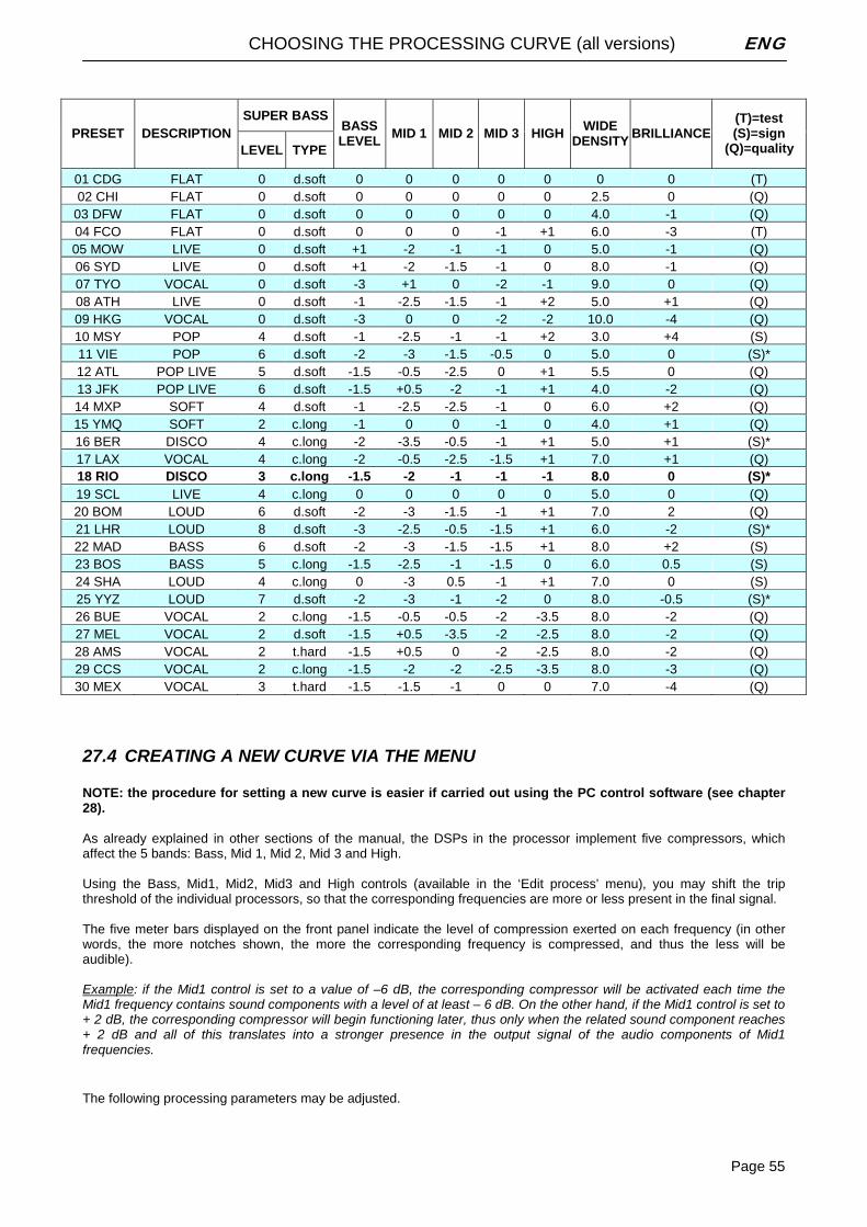
CHOOSING THE PROCESSING CURVE (all versions) ENG
Page 55
SUPER BASS PRESET DESCRIPTION
LEVEL TYPE
BASS LEVEL MID 1 MID 2 MID 3 HIGH WIDE
DENSITY BRILLIANCE (T)=test (S)=sign
(Q)=quality
01 CDG FLAT 0 d.soft 0 0 0 0 0 0 0 (T) 02 CHI FLAT 0 d.soft 0 0 0 0 0 2.5 0 (Q)
03 DFW FLAT 0 d.soft 0 0 0 0 0 4.0 -1 (Q) 04 FCO FLAT 0 d.soft 0 0 0 -1 +1 6.0 -3 (T) 05 MOW LIVE 0 d.soft +1 -2 -1 -1 0 5.0 -1 (Q) 06 SYD LIVE 0 d.soft +1 -2 -1.5 -1 0 8.0 -1 (Q) 07 TYO VOCAL 0 d.soft -3 +1 0 -2 -1 9.0 0 (Q) 08 ATH LIVE 0 d.soft -1 -2.5 -1.5 -1 +2 5.0 +1 (Q) 09 HKG VOCAL 0 d.soft -3 0 0 -2 -2 10.0 -4 (Q) 10 MSY POP 4 d.soft -1 -2.5 -1 -1 +2 3.0 +4 (S) 11 VIE POP 6 d.soft -2 -3 -1.5 -0.5 0 5.0 0 (S)* 12 ATL POP LIVE 5 d.soft -1.5 -0.5 -2.5 0 +1 5.5 0 (Q) 13 JFK POP LIVE 6 d.soft -1.5 +0.5 -2 -1 +1 4.0 -2 (Q) 14 MXP SOFT 4 d.soft -1 -2.5 -2.5 -1 0 6.0 +2 (Q) 15 YMQ SOFT 2 c.long -1 0 0 -1 0 4.0 +1 (Q) 16 BER DISCO 4 c.long -2 -3.5 -0.5 -1 +1 5.0 +1 (S)* 17 LAX VOCAL 4 c.long -2 -0.5 -2.5 -1.5 +1 7.0 +1 (Q) 18 RIO DISCO 3 c.long -1.5 -2 -1 -1 -1 8.0 0 (S)* 19 SCL LIVE 4 c.long 0 0 0 0 0 5.0 0 (Q) 20 BOM LOUD 6 d.soft -2 -3 -1.5 -1 +1 7.0 2 (Q) 21 LHR LOUD 8 d.soft -3 -2.5 -0.5 -1.5 +1 6.0 -2 (S)* 22 MAD BASS 6 d.soft -2 -3 -1.5 -1.5 +1 8.0 +2 (S) 23 BOS BASS 5 c.long -1.5 -2.5 -1 -1.5 0 6.0 0.5 (S) 24 SHA LOUD 4 c.long 0 -3 0.5 -1 +1 7.0 0 (S) 25 YYZ LOUD 7 d.soft -2 -3 -1 -2 0 8.0 -0.5 (S)* 26 BUE VOCAL 2 c.long -1.5 -0.5 -0.5 -2 -3.5 8.0 -2 (Q) 27 MEL VOCAL 2 d.soft -1.5 +0.5 -3.5 -2 -2.5 8.0 -2 (Q) 28 AMS VOCAL 2 t.hard -1.5 +0.5 0 -2 -2.5 8.0 -2 (Q) 29 CCS VOCAL 2 c.long -1.5 -2 -2 -2.5 -3.5 8.0 -3 (Q) 30 MEX VOCAL 3 t.hard -1.5 -1.5 -1 0 0 7.0 -4 (Q)
27.4 CREATING A NEW CURVE VIA THE MENU NOTE: the procedure for setting a new curve is easier if carried out using the PC control software (see chapter 28). As already explained in other sections of the manual, the DSPs in the processor implement five compressors, which affect the 5 bands: Bass, Mid 1, Mid 2, Mid 3 and High. Using the Bass, Mid1, Mid2, Mid3 and High controls (available in the ‘Edit process’ menu), you may shift the trip threshold of the individual processors, so that the corresponding frequencies are more or less present in the final signal. The five meter bars displayed on the front panel indicate the level of compression exerted on each frequency (in other words, the more notches shown, the more the corresponding frequency is compressed, and thus the less will be audible). Example: if the Mid1 control is set to a value of –6 dB, the corresponding compressor will be activated each time the Mid1 frequency contains sound components with a level of at least – 6 dB. On the other hand, if the Mid1 control is set to + 2 dB, the corresponding compressor will begin functioning later, thus only when the related sound component reaches + 2 dB and all of this translates into a stronger presence in the output signal of the audio components of Mid1 frequencies. The following processing parameters may be adjusted.
CHOOSING THE PROCESSING CURVE (all versions) ENG
Page 56
• Super Bass Level The Super Bass Level parameter sets the level of the Bass Enhancer effect added to the sound.
The Bass Enhancer takes the bass signal from the 30Hz-200Hz range, and generates subharmonics that are filtered and modeled by the Super Bass Type, then once again injected onto the bi-channel signal, at the level set via the Super Bass Level control. Super Bass Level may be adjusted from 0.0 to +12.0 dB, with steps of 0.5 dB.
• Super Bass Type The Super Bass Type parameter sets the type of bass added to the sound by the Bass Enhancer. The Bass Enhancer takes the bass signal from the 30Hz-200Hz range, and generates subharmonics that are filtered and modeled by the Super Bass Type, then once again injected onto the bi-channel signal at the level set via the Super Bass Level control. The Super Bass Type may generate three different types of bass:
• Disco Soft Bass (30-Hz range) • Club Long Bass (80-Hz range) • Tight Hard Bass (150-Hz range)
• Bass Level The Bass Level parameter adjusts the threshold level that trips the bass frequency compressor,
affecting the frequency band from 30KHz to 200KHz (see block diagram). The higher the threshold value (f.i. +1 / +2), the less the bass will be compressed, and will thus be more strongly present. A value of 0 means leaving the frequency substantially unchanged. Bass Level may be adjusted from –6.0 to +6.0, with steps of 0.5. No unit of measure is indicated, because this adjustment simultaneously affects multiple compression parameters.
• Mid1 Level The Mid 1 Level parameter adjusts the threshold level that trips the middle-bass frequency compressor, affecting the frequency band from 200KHz to 1.5KHz (see block diagram). The higher the threshold value (f.i. +1 / +2), the less the medium-bass tones will be compressed, and will thus be stronger. A value of 0 means leaving the frequency substantially unchanged. Mid 3 Level may be adjusted from –6.0 to +6.0, with steps of 0.5. No unit of measure is indicated, because this adjustment simultaneously affects multiple compression parameters.
• Mid 2 Level The Mid 2 Level parameter adjusts the threshold level that trips the middle frequency compressor, affecting the frequency band from 1.5KHz to 4.8KHz (see block diagram). The higher the threshold value (f.i. +1 / +2), the less the medium tones will be compressed, and will thus be stronger. A value of 0 means leaving the frequency substantially unchanged. Mid 3 Level may be adjusted from –6.0 to +6.0, with steps of 0.5. No unit of measure is indicated, because this adjustment simultaneously affects multiple compression parameters.
• Mid 3 Level The Mid 3 Level parameter adjusts the threshold level that trips the middle-high frequency compressor, affecting the frequency band from 4.8KHz to 9.5KHz (see block diagram). The higher the threshold value (f.i. +1 / +2), the less the medium-high tones will be compressed, and will thus be stronger. A value of 0 means leaving the frequency substantially unchanged. Mid 3 Level may be adjusted from –6.0 to +6.0, with steps of 0.5. No unit of measure is indicated, because this adjustment simultaneously affects multiple compression parameters.
• High Level The High Level parameter adjusts the threshold level that trips the high frequency compressor, affecting the frequency band from 9.5KHz to 15KHz (see block diagram). The higher the threshold value (f.i. +1 / +2), the less the high frequencies will be compressed, and will thus be more strongly present. A value of 0 means leaving the frequency substantially unchanged. High Level may be adjusted from –6.0 to +6.0, with steps of 0.5. No unit of measure is indicated, because this adjustment simultaneously affects multiple compression parameters.
• Wide Density The Wide Density parameter adjusts the compression level throughout the band, increasing the average signal level (while reducing dynamics). The frequency deviation remains within 75 KHz. Wide Density may be adjusted from 0.0 to +12.0 dB, with steps of 0.5 dB. High density values provide the transmitted signal with a strong ‘presence’, while reducing the dynamics of the signal. We recommend using low-density profiles for programs based on classical and symphony music.
• Brilliance The Brilliance parameter adjusts the HF limiter level, for better definition of the high frequencies. It may be adjusted within a range of –6.0 to +6.0, with steps of 0.5. No unit of measure is indicated, because this adjustment simultaneously affects multiple compression parameters. A value of 0 means leaving the frequency substantially unchanged; values <0 make the parameter more incisive, while values >0 reduce its effects. Its effects are especially strongly felt when the transmitting pre-emphasis is the one generated by the processor.
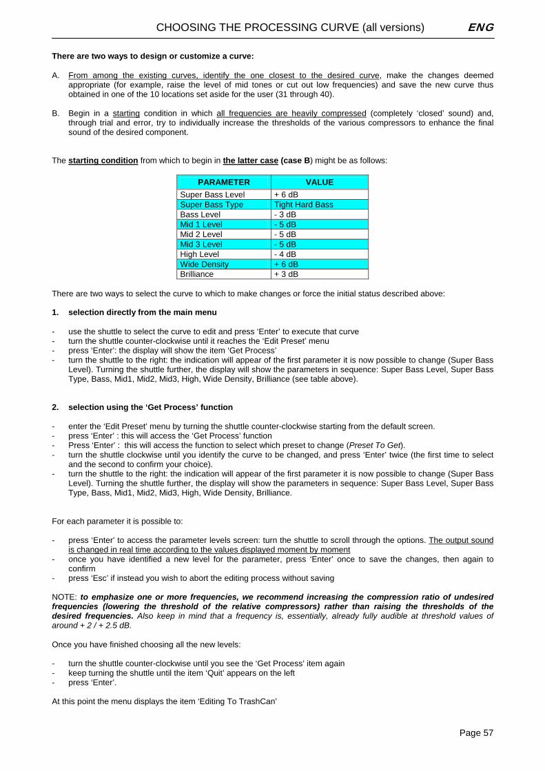
CHOOSING THE PROCESSING CURVE (all versions) ENG
Page 57
There are two ways to design or customize a curve: A. From among the existing curves, identify the one closest to the desired curve, make the changes deemed
appropriate (for example, raise the level of mid tones or cut out low frequencies) and save the new curve thus obtained in one of the 10 locations set aside for the user (31 through 40).
B. Begin in a starting condition in which all frequencies are heavily compressed (completely ‘closed’ sound) and,
through trial and error, try to individually increase the thresholds of the various compressors to enhance the final sound of the desired component.
The starting condition from which to begin in the latter case (case B) might be as follows:
PARAMETER VALUE
Super Bass Level + 6 dB Super Bass Type Tight Hard Bass Bass Level - 3 dB Mid 1 Level - 5 dB Mid 2 Level - 5 dB Mid 3 Level - 5 dB High Level - 4 dB Wide Density + 6 dB Brilliance + 3 dB
There are two ways to select the curve to which to make changes or force the initial status described above: 1. selection directly from the main menu - use the shuttle to select the curve to edit and press ‘Enter’ to execute that curve - turn the shuttle counter-clockwise until it reaches the ‘Edit Preset’ menu - press ‘Enter’: the display will show the item ‘Get Process’ - turn the shuttle to the right: the indication will appear of the first parameter it is now possible to change (Super Bass
Level). Turning the shuttle further, the display will show the parameters in sequence: Super Bass Level, Super Bass Type, Bass, Mid1, Mid2, Mid3, High, Wide Density, Brilliance (see table above).
2. selection using the ‘Get Process’ function - enter the ‘Edit Preset’ menu by turning the shuttle counter-clockwise starting from the default screen. - press ‘Enter’ : this will access the ‘Get Process’ function - Press ‘Enter’ : this will access the function to select which preset to change (Preset To Get). - turn the shuttle clockwise until you identify the curve to be changed, and press ‘Enter’ twice (the first time to select
and the second to confirm your choice). - turn the shuttle to the right: the indication will appear of the first parameter it is now possible to change (Super Bass
Level). Turning the shuttle further, the display will show the parameters in sequence: Super Bass Level, Super Bass Type, Bass, Mid1, Mid2, Mid3, High, Wide Density, Brilliance.
For each parameter it is possible to: - press ‘Enter’ to access the parameter levels screen: turn the shuttle to scroll through the options. The output sound
is changed in real time according to the values displayed moment by moment - once you have identified a new level for the parameter, press ‘Enter’ once to save the changes, then again to
confirm - press ‘Esc’ if instead you wish to abort the editing process without saving NOTE: to emphasize one or more frequencies, we recommend increasing the compression ratio of undesired frequencies (lowering the threshold of the relative compressors) rather than raising the thresholds of the desired frequencies. Also keep in mind that a frequency is, essentially, already fully audible at threshold values of around + 2 / + 2.5 dB. Once you have finished choosing all the new levels:
- turn the shuttle counter-clockwise until you see the ‘Get Process’ item again - keep turning the shuttle until the item ‘Quit’ appears on the left - press ‘Enter’. At this point the menu displays the item ‘Editing To TrashCan’
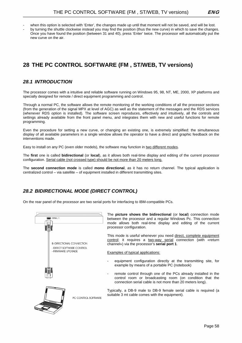
THE PC CONTROL SOFTWARE (FM , ST/WEB, TV versions) ENG
Page 58
- when this option is selected with ‘Enter’, the changes made up until that moment will not be saved, and will be lost. - by turning the shuttle clockwise instead you may find the position (thus the new curve) in which to save the changes.
Once you have found the position (between 31 and 40), press ‘Enter’ twice. The processor will automatically put the new curve on the air.
28 THE PC CONTROL SOFTWARE (FM , ST/WEB, TV versions)
28.1 INTRODUCTION The processor comes with a intuitive and reliable software running on Windows 95, 98, NT, ME, 2000, XP platforms and specially designed for remote / direct equipment programming and control. Through a normal PC, the software allows the remote monitoring of the working conditions of all the processor sections (from the generation of the signal MPX at level of AGC) as well as the statement of the messages and the RDS services (whenever RDS option is installed). The software screen reproduces, effectively and intuitively, all the controls and settings already available from the front panel menu, and integrates them with new and useful functions for remote programming. Even the procedure for setting a new curve, or changing an existing one, is extremely simplified: the simultaneous display of all available parameters in a single window allows the operator to have a direct and graphic feedback on the interventions made. Easy to install on any PC (even older models), the software may function in two different modes. The first one is called bidirectional (or local), as it allows both real-time display and editing of the current processor configuration. Serial cable (not crossed type) should be not more than 20 meters long. The second connection mode is called mono directional, as it has no return channel. The typical application is centralized control – via satellite – of equipment installed in different transmitting sites.
28.2 BIDIRECTIONAL MODE (DIRECT CONTROL) On the rear panel of the processor are two serial ports for interfacing to IBM-compatible PCs.
The picture shows the bidirectional (or local) connection mode between the processor and a regular Windows Pc. This connection mode allows both real-time display and editing of the current processor configuration. This mode is useful whenever you need direct, complete equipment control; it requires a two-way serial connection (with «return channel») via the processor’s serial port 1. Examples of typical applications: - equipment configuration directly at the transmitting site, for
example by means of a portable PC (notebook) - remote control through one of the PCs already installed in the
control room or broadcasting room (on condition that the connection serial cable is not more than 20 meters long).
Typically, a DB-9 male to DB-9 female serial cable is required (a suitable 3 mt cable comes with the equipment).
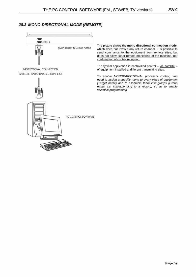
THE PC CONTROL SOFTWARE (FM , ST/WEB, TV versions) ENG
Page 59
28.3 MONO-DIRECTIONAL MODE (REMOTE)
The picture shows the mono directional connection mode, which does not involve any return channel. It is possible to send commands to the equipment from remote sites, but does not allow either remote monitoring of the machine, nor confirmation of control reception. The typical application is centralized control – via satellite – of equipment installed at different transmitting sites. To enable MONODIRECTIONAL processor control, You need to assign a specific name to every piece of equipment (Target name) and to assemble them into groups (Group name, i.e. corresponding to a region), so as to enable selective programming
THE PC CONTROL SOFTWARE (FM , ST/WEB, TV versions) ENG
Page 60
28.4 INSTALLATION A) Using standard Windows procedures, access the PC REMOTE SOFTWARE folder and run the SETUP.EXE file under the Microsoft Windows® ’95, ’98, ME, 2000, NT and XP operating system. B) The install program installs Pc remote Control application onto the computer's hard disk. The installation screen will also suggest a destination directory for the software. If You have a reason to specify another directory for installation, use the Browse button or type an alternative path. C) Click to Install and Next to complete installation. This takes only a few seconds. When the software is successfully installed, Finish message will appear at the bottom of the installing box. Click Close to close the installation screen. D) Standard Windows procedures can be used to create a shortcut to the program on the desktop. it is advised to completely uninstall possible existing older versions before running the new one. To uninstall the exisiting Pc control software, proceed as follows: - enter the Windows «Control Panel» - click on the « Install Applications » icon - choose the item of current version from the list and select it - click on the «Add/Remove» button - confirm deletion of all proposed files - run the new Remote Control program starting from the 'Programs' Menu of the Start button on Yr Pc
There is a direct correspondence between the firmware and software versions. For example, the rel. 3.0 of Pc software requires the firmware version 3.0 installed on the processor and viceversa. More precisely, the two first digits must match, as possible sub-releases (identified by the third digit) are not involved in the firmware/software compatibility. As general rule, software version X.Y.Z runs with firmware version X.Y.K
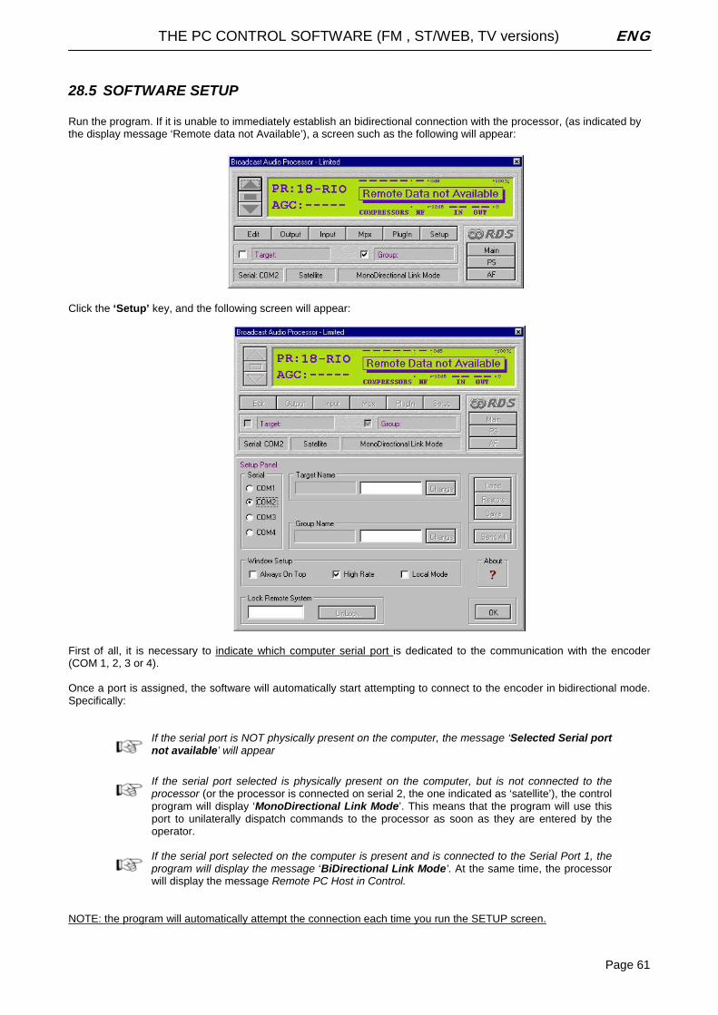
THE PC CONTROL SOFTWARE (FM , ST/WEB, TV versions) ENG
Page 61
28.5 SOFTWARE SETUP Run the program. If it is unable to immediately establish an bidirectional connection with the processor, (as indicated by the display message ‘Remote data not Available’), a screen such as the following will appear: Click the ‘Setup’ key, and the following screen will appear:
First of all, it is necessary to indicate which computer serial port is dedicated to the communication with the encoder (COM 1, 2, 3 or 4). Once a port is assigned, the software will automatically start attempting to connect to the encoder in bidirectional mode. Specifically:
If the serial port is NOT physically present on the computer, the message ‘Selected Serial port not available’ will appear
If the serial port selected is physically present on the computer, but is not connected to the processor (or the processor is connected on serial 2, the one indicated as ‘satellite’), the control program will display ‘MonoDirectional Link Mode’. This means that the program will use this port to unilaterally dispatch commands to the processor as soon as they are entered by the operator.
If the serial port selected on the computer is present and is connected to the Serial Port 1, the program will display the message ‘BiDirectional Link Mode’. At the same time, the processor will display the message Remote PC Host in Control.
NOTE: the program will automatically attempt the connection each time you run the SETUP screen.
THE PC CONTROL SOFTWARE (FM , ST/WEB, TV versions) ENG
Page 62
It is now possible to set up or modify some modes regarding the software window display on the computer screen, and communications between the computer and the processor. - If selected, the option ‘Always On Top’ will always keep the control program window in the foreground of the
desktop.
- If selected, the option ‘High Rate’ allows you to select the higher refresh speed (30 Hz) in displaying the Vu Meter on the screen. Choose the default speed (10 Hz) if the higher speed does not allow smooth display of the meters.
- If selected, the option ‘Local mode’ allows you to ‘force’ a second connection attempt by the software to the
processor. Please note that this option is automatically selected by the software, and that manual intervention may only be necessary in certain rare instances.
28.6 LOAD, SAVE AND RESTORE FUNCTIONS It is possible to save and immediately recall any configuration / setting of the processor using the Load, Save and Restore keys present on the Setup screen. The window shows some files pre-loaded. These are files regarding some of the most commonly used configurations: - ByPass_Mpx Test enables the ‘bypass’ processor setting - Modulation_Reference_Tone enables the setting to generate the ‘Reference Tone’ - Rds_AF_Method_A_Demo shows an example of setting the Alternative Frequency RDS per method A - Rds_AF_Method_B_Demo shows an example of setting the Alternative Frequency RDS per method B - Rds_Ps_Scrolling_Demo shows an example of setting up a scrolling PS message - Rds_Sequence_Demo shows an example of setting up a standard PS message
28.7 LOADING AN EXISTING CONFIGURATION - Click the Load key: it will open a window showing all the available configuration files. These files have the extension
apc (audio processor configuration). - Select the desired file and click ‘open’. - At this point, the software allows you to check the level of all parameters regarding the chosen configuration, without
allowing you to edit them (‘View only’ mode). To edit, exit the Setup window (by pressing OK in the lower right) and access the single configuration windows.
- Once you are certain that the correct configuration has been chosen, you may possible load that configuration into
the processor via the ‘Send All’ button. - If the configuration you are about to load is not the desired one, you may exit the procedure using the ‘Restore’
button (see below).
28.8 SAVING THE CURRENT CONFIGURATION
Any operative configuration of the processor (input gain, pilot level, RDS messages, enable status of RDS services, etc.) may be saved at any time. To do so, simply press the ‘Save’ button and indicate the name with which to save the configuration (for example, the operator’s name). Note that the preset (processing curve) broadcasting is not included in this saving operation.

THE PC CONTROL SOFTWARE (FM , ST/WEB, TV versions) ENG
Page 63
28.9 THE ‘RESTORE’ FUNCTION The ‘Restore’ function allows you to automatically reload the configuration present the last time the control program was closed. This is especially useful when you have inadvertently changed certain parameters or made configuration mistakes. The ‘Restore’ procedure is • Click the corresponding key and then ‘Ok’ • Make sure that the configuration to be loaded is the one desired • Click the ‘Send All’ button to reload the configuration into the processor memory.
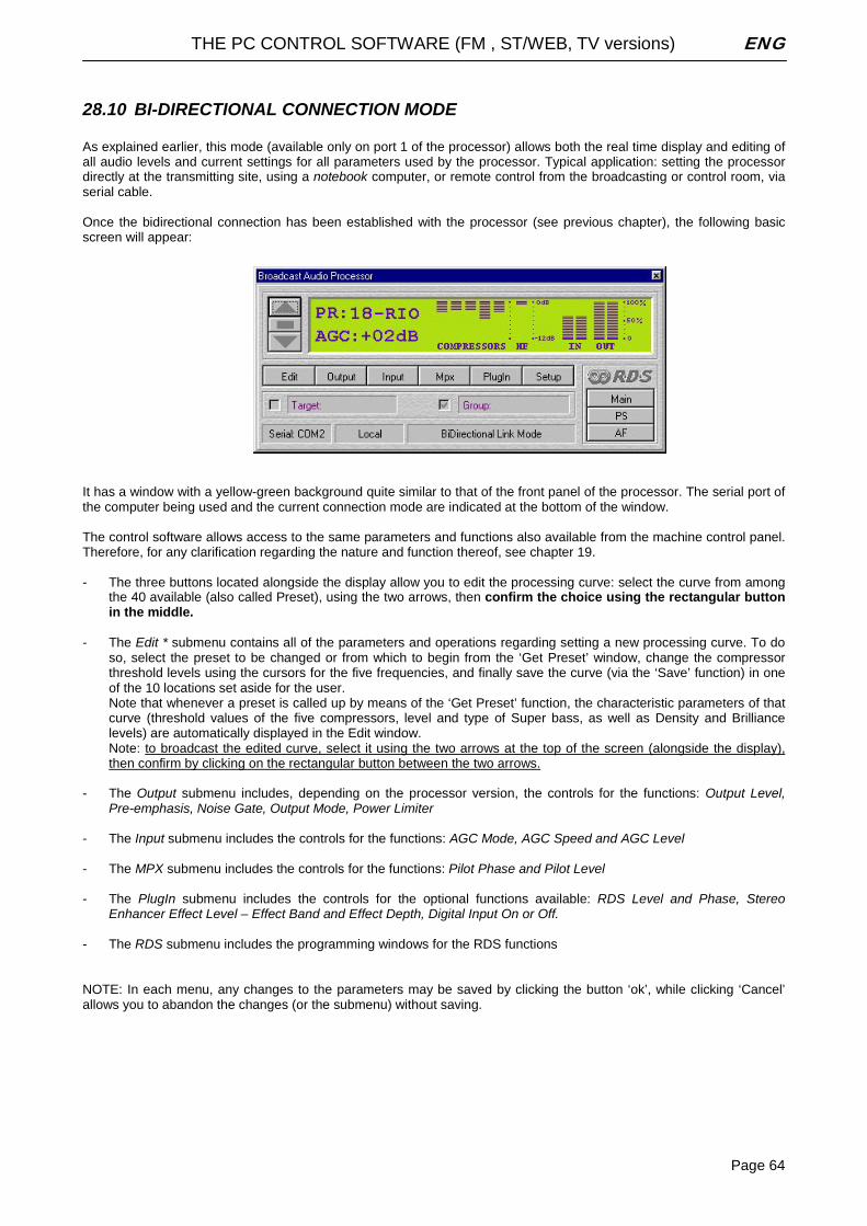
THE PC CONTROL SOFTWARE (FM , ST/WEB, TV versions) ENG
Page 64
28.10 BI-DIRECTIONAL CONNECTION MODE As explained earlier, this mode (available only on port 1 of the processor) allows both the real time display and editing of all audio levels and current settings for all parameters used by the processor. Typical application: setting the processor directly at the transmitting site, using a notebook computer, or remote control from the broadcasting or control room, via serial cable. Once the bidirectional connection has been established with the processor (see previous chapter), the following basic screen will appear:
It has a window with a yellow-green background quite similar to that of the front panel of the processor. The serial port of the computer being used and the current connection mode are indicated at the bottom of the window. The control software allows access to the same parameters and functions also available from the machine control panel. Therefore, for any clarification regarding the nature and function thereof, see chapter 19. - The three buttons located alongside the display allow you to edit the processing curve: select the curve from among
the 40 available (also called Preset), using the two arrows, then confirm the choice using the rectangular button in the middle.
- The Edit * submenu contains all of the parameters and operations regarding setting a new processing curve. To do
so, select the preset to be changed or from which to begin from the ‘Get Preset’ window, change the compressor threshold levels using the cursors for the five frequencies, and finally save the curve (via the ‘Save’ function) in one of the 10 locations set aside for the user. Note that whenever a preset is called up by means of the ‘Get Preset’ function, the characteristic parameters of that curve (threshold values of the five compressors, level and type of Super bass, as well as Density and Brilliance levels) are automatically displayed in the Edit window. Note: to broadcast the edited curve, select it using the two arrows at the top of the screen (alongside the display), then confirm by clicking on the rectangular button between the two arrows.
- The Output submenu includes, depending on the processor version, the controls for the functions: Output Level,
Pre-emphasis, Noise Gate, Output Mode, Power Limiter - The Input submenu includes the controls for the functions: AGC Mode, AGC Speed and AGC Level - The MPX submenu includes the controls for the functions: Pilot Phase and Pilot Level - The PlugIn submenu includes the controls for the optional functions available: RDS Level and Phase, Stereo
Enhancer Effect Level – Effect Band and Effect Depth, Digital Input On or Off. - The RDS submenu includes the programming windows for the RDS functions NOTE: In each menu, any changes to the parameters may be saved by clicking the button ‘ok’, while clicking ‘Cancel’ allows you to abandon the changes (or the submenu) without saving.
THE PC CONTROL SOFTWARE (FM , ST/WEB, TV versions) ENG
Page 65
28.11 THE ‘TARGET NAME AND GROUP NAME’ IDENTIFIERS As explained in the introduction, in bidirectional connection mode (local) it is possible to assign each processor with a specific identification code (called the ‘Target Name’), as well as a classification group, which is useful when you wish to selectively program the processor from remote sites over a unidirectional connection (see next chapter). - To do so, open the submenu ‘Setup’ and enter the Target Name and/or Group Name (it is not essential to assign
both) in the spaces provided. Each word must be made up of a maximum of 8 characters (upper or lower case), without spaces. Be careful not to assign the same Target name or the same Group name to two different devices. Once you have finished entering information, click the ‘Change’ button
For example, a national network could assign the Group Name field to the region where the processor is in operation, and give the Target name the name of the town hosting the broadcasting site, or the city covered by that site. For example, suppose you have 3 processors in the Tuscany region (the first covers Lucca, the second Florence and the third Pisa) and 4 others in the Marches (Pesaro, Ancona, Urbino, Macerata). The Target name and Group Name will be programmed for the individual machines as follows: Group name = Tuscany, Target Name = Lucca for the first processor, Group name = Tuscany, Target Name = Florence for the second processor, etc. NOTE: the Target Name and Group Name windows at the top of the screen are disabled, since these access keys may be used for programming the processors only in unidirectional connection mode.
28.12 PROCESSOR PANEL LOCK FUNCTION The ‘Lock Remote System’ option allows you to block any access to the processor parameters via the front panel. Locking/unlocking can only take place via control software, by entering the password in the space provided in the Setup window. To activate the lock function, type a password and then click on the corresponding button next to it (Lock). You may remove the connection to the PC. To unlock the panel, type the same password, and then click on Unlock. Note: the password may be changed during each access.
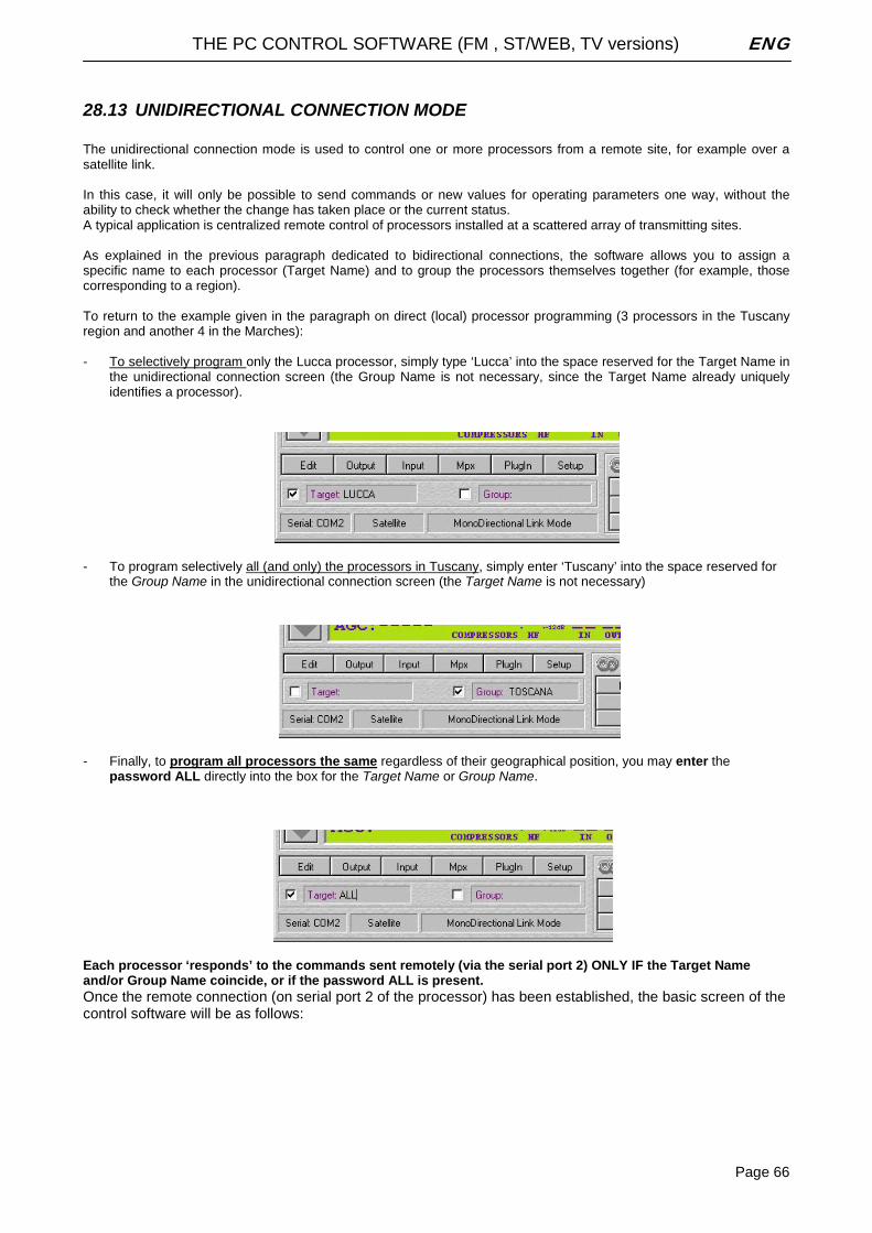
THE PC CONTROL SOFTWARE (FM , ST/WEB, TV versions) ENG
Page 66
28.13 UNIDIRECTIONAL CONNECTION MODE The unidirectional connection mode is used to control one or more processors from a remote site, for example over a satellite link. In this case, it will only be possible to send commands or new values for operating parameters one way, without the ability to check whether the change has taken place or the current status. A typical application is centralized remote control of processors installed at a scattered array of transmitting sites. As explained in the previous paragraph dedicated to bidirectional connections, the software allows you to assign a specific name to each processor (Target Name) and to group the processors themselves together (for example, those corresponding to a region). To return to the example given in the paragraph on direct (local) processor programming (3 processors in the Tuscany region and another 4 in the Marches): - To selectively program only the Lucca processor, simply type ‘Lucca’ into the space reserved for the Target Name in
the unidirectional connection screen (the Group Name is not necessary, since the Target Name already uniquely identifies a processor).
- To program selectively all (and only) the processors in Tuscany, simply enter ‘Tuscany’ into the space reserved for
the Group Name in the unidirectional connection screen (the Target Name is not necessary)
- Finally, to program all processors the same regardless of their geographical position, you may enter the
password ALL directly into the box for the Target Name or Group Name.
Each processor ‘responds’ to the commands sent remotely (via the serial port 2) ONLY IF the Target Name and/or Group Name coincide, or if the password ALL is present. Once the remote connection (on serial port 2 of the processor) has been established, the basic screen of the control software will be as follows:
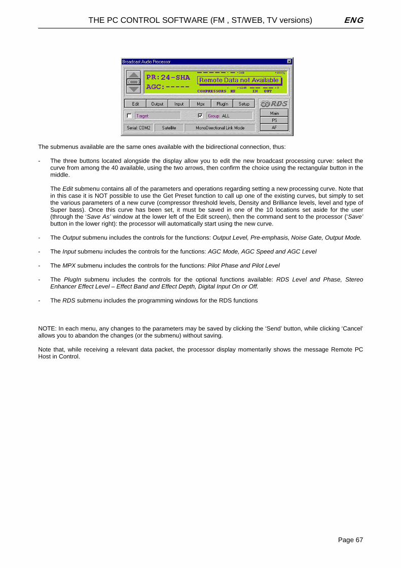
THE PC CONTROL SOFTWARE (FM , ST/WEB, TV versions) ENG
Page 67
The submenus available are the same ones available with the bidirectional connection, thus: - The three buttons located alongside the display allow you to edit the new broadcast processing curve: select the
curve from among the 40 available, using the two arrows, then confirm the choice using the rectangular button in the middle.
The Edit submenu contains all of the parameters and operations regarding setting a new processing curve. Note that in this case it is NOT possible to use the Get Preset function to call up one of the existing curves, but simply to set the various parameters of a new curve (compressor threshold levels, Density and Brilliance levels, level and type of Super bass). Once this curve has been set, it must be saved in one of the 10 locations set aside for the user (through the ‘Save As’ window at the lower left of the Edit screen), then the command sent to the processor (‘Save’ button in the lower right): the processor will automatically start using the new curve.
- The Output submenu includes the controls for the functions: Output Level, Pre-emphasis, Noise Gate, Output Mode. - The Input submenu includes the controls for the functions: AGC Mode, AGC Speed and AGC Level - The MPX submenu includes the controls for the functions: Pilot Phase and Pilot Level - The PlugIn submenu includes the controls for the optional functions available: RDS Level and Phase, Stereo
Enhancer Effect Level – Effect Band and Effect Depth, Digital Input On or Off. - The RDS submenu includes the programming windows for the RDS functions NOTE: In each menu, any changes to the parameters may be saved by clicking the ‘Send’ button, while clicking ‘Cancel’ allows you to abandon the changes (or the submenu) without saving. Note that, while receiving a relevant data packet, the processor display momentarily shows the message Remote PC Host in Control.
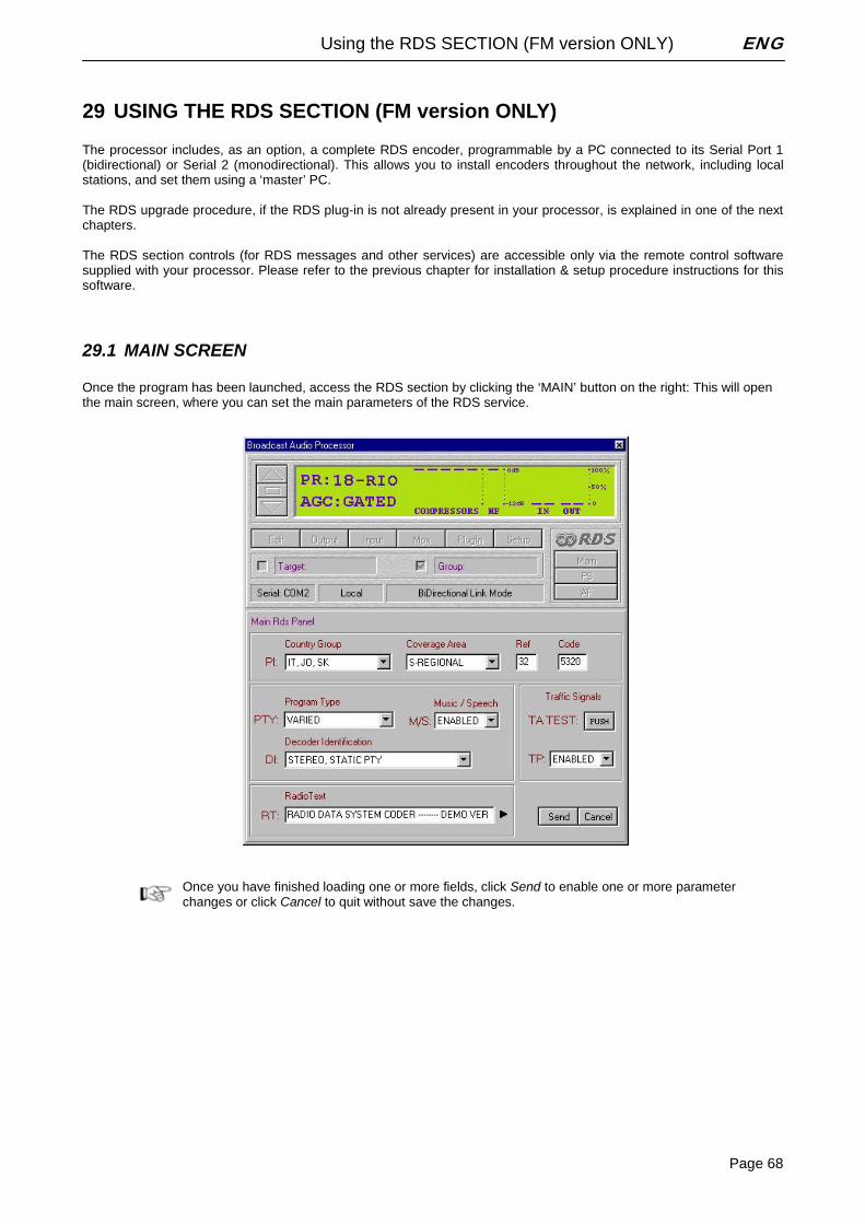
Using the RDS SECTION (FM version ONLY) ENG
Page 68
29 USING THE RDS SECTION (FM version ONLY) The processor includes, as an option, a complete RDS encoder, programmable by a PC connected to its Serial Port 1 (bidirectional) or Serial 2 (monodirectional). This allows you to install encoders throughout the network, including local stations, and set them using a ‘master’ PC. The RDS upgrade procedure, if the RDS plug-in is not already present in your processor, is explained in one of the next chapters. The RDS section controls (for RDS messages and other services) are accessible only via the remote control software supplied with your processor. Please refer to the previous chapter for installation & setup procedure instructions for this software.
29.1 MAIN SCREEN Once the program has been launched, access the RDS section by clicking the ‘MAIN’ button on the right: This will open the main screen, where you can set the main parameters of the RDS service.
Once you have finished loading one or more fields, click Send to enable one or more parameter changes or click Cancel to quit without save the changes.
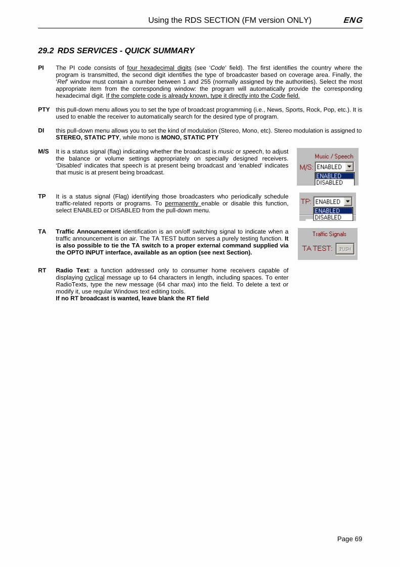
Using the RDS SECTION (FM version ONLY) ENG
Page 69
29.2 RDS SERVICES - QUICK SUMMARY PI The PI code consists of four hexadecimal digits (see ‘Code’ field). The first identifies the country where the
program is transmitted, the second digit identifies the type of broadcaster based on coverage area. Finally, the ‘Ref’ window must contain a number between 1 and 255 (normally assigned by the authorities). Select the most appropriate item from the corresponding window: the program will automatically provide the corresponding hexadecimal digit. If the complete code is already known, type it directly into the Code field.
PTY this pull-down menu allows you to set the type of broadcast programming (i.e., News, Sports, Rock, Pop, etc.). It is
used to enable the receiver to automatically search for the desired type of program. DI this pull-down menu allows you to set the kind of modulation (Stereo, Mono, etc). Stereo modulation is assigned to
STEREO, STATIC PTY, while mono is MONO, STATIC PTY M/S It is a status signal (flag) indicating whether the broadcast is music or speech, to adjust
the balance or volume settings appropriately on specially designed receivers. ‘Disabled’ indicates that speech is at present being broadcast and ‘enabled’ indicates that music is at present being broadcast.
TP It is a status signal (Flag) identifying those broadcasters who periodically schedule
traffic-related reports or programs. To permanently enable or disable this function, select ENABLED or DISABLED from the pull-down menu.
TA Traffic Announcement identification is an on/off switching signal to indicate when a
traffic announcement is on air. The TA TEST button serves a purely testing function. It is also possible to tie the TA switch to a proper external command supplied via the OPTO INPUT interface, available as an option (see next Section).
RT Radio Text: a function addressed only to consumer home receivers capable of
displaying cyclical message up to 64 characters in length, including spaces. To enter RadioTexts, type the new message (64 char max) into the field. To delete a text or modify it, use regular Windows text editing tools. If no RT broadcast is wanted, leave blank the RT field
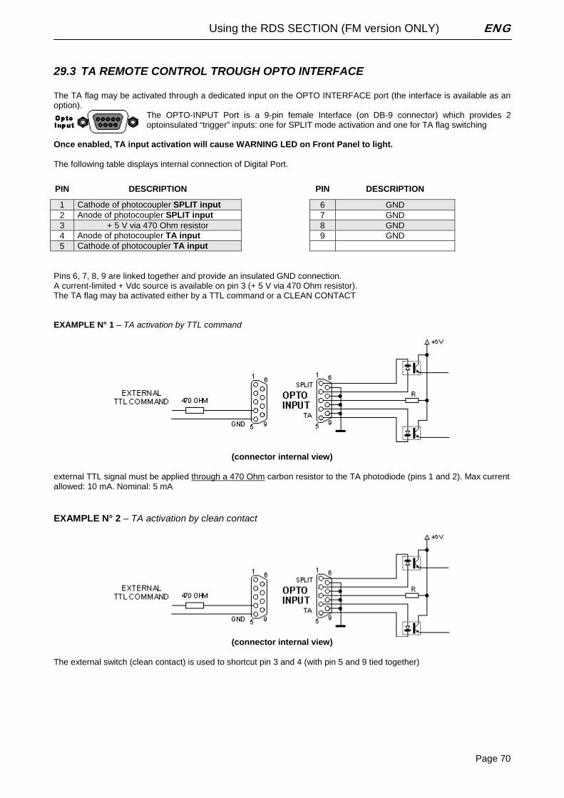
Using the RDS SECTION (FM version ONLY) ENG
Page 70
29.3 TA REMOTE CONTROL TROUGH OPTO INTERFACE The TA flag may be activated through a dedicated input on the OPTO INTERFACE port (the interface is available as an option).
The OPTO-INPUT Port is a 9-pin female Interface (on DB-9 connector) which provides 2 optoinsulated “trigger” inputs: one for SPLIT mode activation and one for TA flag switching
Once enabled, TA input activation will cause WARNING LED on Front Panel to light. The following table displays internal connection of Digital Port.
PIN DESCRIPTION PIN DESCRIPTION
1 Cathode of photocoupler SPLIT input 6 GND 2 Anode of photocoupler SPLIT input 7 GND 3 + 5 V via 470 Ohm resistor 8 GND 4 Anode of photocoupler TA input 9 GND 5 Cathode of photocoupler TA input
Pins 6, 7, 8, 9 are linked together and provide an insulated GND connection. A current-limited + Vdc source is available on pin 3 (+ 5 V via 470 Ohm resistor). The TA flag may ba activated either by a TTL command or a CLEAN CONTACT EXAMPLE N° 1 – TA activation by TTL command
(connector internal view)
external TTL signal must be applied through a 470 Ohm carbon resistor to the TA photodiode (pins 1 and 2). Max current allowed: 10 mA. Nominal: 5 mA
EXAMPLE N° 2 – TA activation by clean contact
(connector internal view)
The external switch (clean contact) is used to shortcut pin 3 and 4 (with pin 5 and 9 tied together)
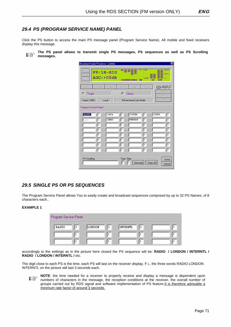
Using the RDS SECTION (FM version ONLY) ENG
Page 71
29.4 PS (PROGRAM SERVICE NAME) PANEL Click the PS button to access the main PS message panel (Program Service Name). All mobile and fixed receivers display this message.
The PS panel allows to transmit single PS messages, PS sequences as well as PS Scrolling messages.
29.5 SINGLE PS OR PS SEQUENCES The Program Service Panel allows You to easily create and broadcast sequences composed by up to 32 PS Names, of 8 characters each.. EXAMPLE 1
accordingly to the settings as in the picture here closed the PS sequence will be: RADIO / LONDON / INTERNTL / RADIO / LONDON / INTERNTL / etc. The digit close to each PS is the time, each PS will last on the receiver display. F.i., the three words RADIO LONDON INTERNTL on the picture will last 3 seconds each.
NOTE: the time needed for a receiver to properly receive and display a message is dependent upon numbers of characters in the message, the reception conditions at the receiver, the overall number of groups carried out by RDS signal and software implementation of PS feature.It is therefore advisable a minimum rate factor of around 3 seconds.
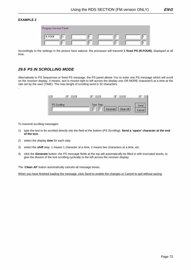
Using the RDS SECTION (FM version ONLY) ENG
Page 72
EXAMPLE 2
Accordingly to the settings in the picture here eabove, the processor will transmit 1 fixed PS (R.FOUR), displayed at all time.
29.6 PS IN SCROLLING MODE Alternatively to PS Sequences or fixed PS message, the PS panel allows You to enter one PS message which will scroll on the receiver display. It means, text is moved right to left across the display one OR MORE characterS at a time at the rate set by the user (TIME). The max lenght of scrolling word is 32 characters. .
To transmit scrolling messages: 1) type the text to be scrolled directly into the field at the bottom (PS Scrolling). Send a ‘space’ character at the end
of the text. 2) select the display time for each step 3) select the shift step. 1 means 1 character at a time, 2 means two characters at a time, etc. 4) click the Generate button: the PS message fields at the top will automatically be filled in with truncated words, to
give the illusion of the text scrolling cyclically to the left across the receiver display. The ‘Clean All’ button automatically cancels all message boxes. When you have finished loading the message, click Send to enable the changes or Cancel to quit without saving.
Using the RDS SECTION (FM version ONLY) ENG
Page 73
29.7 HINTS AND TIPS ABOUT DYNAMIC PS MODE When programming PS durations in Dynamic mode, two ‘gold’ rules should be taken into account. They are related to the ‘physics’ of RDS channels and are completely independent from RDS encoder architecture.
WARNING: if the PS is constantly changed (as in the PS Scrolling mode), it is possible that some receivers will display a mixture of old and new PS message on the same display. In some cases, no PS will be displayed at all. This may occurs as message byte group order is not univocally recommended by the CENELEC RDS standard and strictly depends on the coder/decoder physical implementation. Neither the RDS encoder in the processor nor the car receiver are faulty. In case of PS Scrolling selection, we therefore suggest to choose low display speeds. PS scrolling and PS Sequence mode are against the broadcast regulations of most countries: refer to appropriate ‘governing body’ for further information. The encoder’s manufacturer can not be held responsible for uncorrect PS use!
Drivers CAN NOT look at messages displayed on their radio cars longer than a few seconds. LONG PS SEQUENCES are therefore not only be distracting car driver but they are simply.... not read! Furthermore, they affect the quality of RDS broadcasting overall, as the Radio Station default Name refresh could be not frequent enough. PS scrolling lenght has been thus intentionally limited to 32 characters, as that lenght is largely suitable for a large set of meaningful messages. Message synthesis... means quality in Dynamic RDS broadcasting
29.8 ALTERNATIVE FREQUENCIES LIST The list(s) of alternative frequencies give information on the various transmitters broadcasting the same programme in the same or adjacent reception areas, and enable receivers equipped with a memory to store the list(s), to reduce the time for switching to another transmitter. This facility is particularly useful in the case of car and portable radios. The alternative frequencies (AF) list can be transmitted following two methods: A Method and B Method (see next page). In both methods the alternative frequencies lists must contain only the frequencies of the adjacent transmitters and repeaters with overlapped transmitting areas. To compile the AF lists use the following procedure: - Choose one of the 8 lists ( from AF1 to AF8) - Select the AF from the available frequencies in the left window and drag & drop it into the AF list - To remove a frequency from the list follow the procedure drag & drop to move to ‘recycle bin’ or cancel them by
pressing on the ‘Cancel’ button. A second loading procedure is provided: - Click the label of the AF List to be filled (f.i., click AF2 label): it will turn red - Double click the frequencies listed on the left window: selected frequencies will be automatically loaded into the
highlighted list. Lists containing at least one AF are shown in blu color.
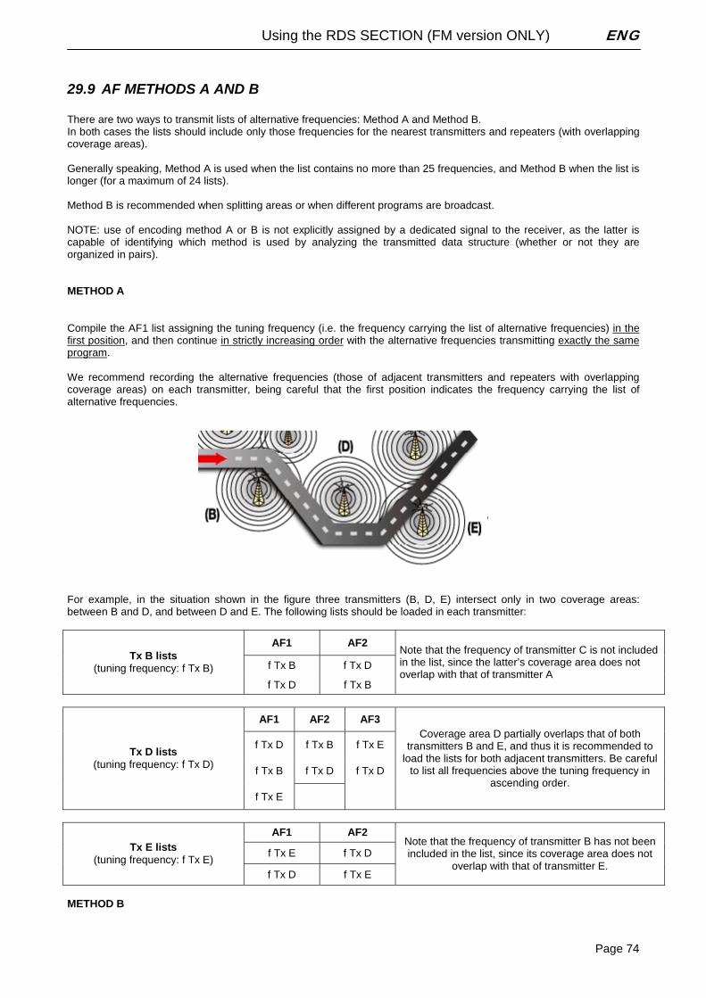
Using the RDS SECTION (FM version ONLY) ENG
Page 74
29.9 AF METHODS A AND B There are two ways to transmit lists of alternative frequencies: Method A and Method B. In both cases the lists should include only those frequencies for the nearest transmitters and repeaters (with overlapping coverage areas). Generally speaking, Method A is used when the list contains no more than 25 frequencies, and Method B when the list is longer (for a maximum of 24 lists). Method B is recommended when splitting areas or when different programs are broadcast. NOTE: use of encoding method A or B is not explicitly assigned by a dedicated signal to the receiver, as the latter is capable of identifying which method is used by analyzing the transmitted data structure (whether or not they are organized in pairs). METHOD A Compile the AF1 list assigning the tuning frequency (i.e. the frequency carrying the list of alternative frequencies) in the first position, and then continue in strictly increasing order with the alternative frequencies transmitting exactly the same program. We recommend recording the alternative frequencies (those of adjacent transmitters and repeaters with overlapping coverage areas) on each transmitter, being careful that the first position indicates the frequency carrying the list of alternative frequencies.
For example, in the situation shown in the figure three transmitters (B, D, E) intersect only in two coverage areas: between B and D, and between D and E. The following lists should be loaded in each transmitter:
AF1 AF2
f Tx B f Tx D Tx B lists
(tuning frequency: f Tx B)
f Tx D f Tx B
Note that the frequency of transmitter C is not included in the list, since the latter’s coverage area does not overlap with that of transmitter A
AF1 AF2 AF3
f Tx D f Tx B f Tx E
f Tx B f Tx D f Tx D
Tx D lists (tuning frequency: f Tx D)
f Tx E
Coverage area D partially overlaps that of both transmitters B and E, and thus it is recommended to
load the lists for both adjacent transmitters. Be careful to list all frequencies above the tuning frequency in
ascending order.
AF1 AF2
f Tx E f Tx D Tx E lists (tuning frequency: f Tx E)
f Tx D f Tx E
Note that the frequency of transmitter B has not been included in the list, since its coverage area does not
overlap with that of transmitter E.
METHOD B
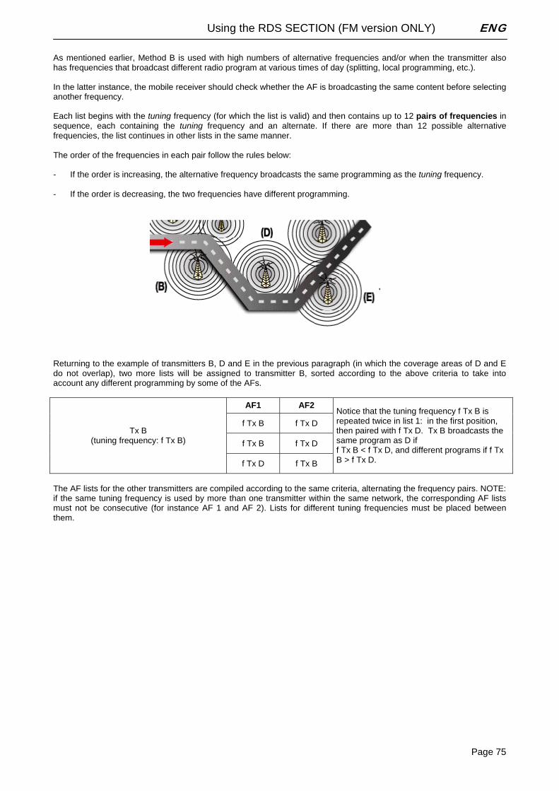
Using the RDS SECTION (FM version ONLY) ENG
Page 75
As mentioned earlier, Method B is used with high numbers of alternative frequencies and/or when the transmitter also has frequencies that broadcast different radio program at various times of day (splitting, local programming, etc.). In the latter instance, the mobile receiver should check whether the AF is broadcasting the same content before selecting another frequency. Each list begins with the tuning frequency (for which the list is valid) and then contains up to 12 pairs of frequencies in sequence, each containing the tuning frequency and an alternate. If there are more than 12 possible alternative frequencies, the list continues in other lists in the same manner. The order of the frequencies in each pair follow the rules below: - If the order is increasing, the alternative frequency broadcasts the same programming as the tuning frequency. - If the order is decreasing, the two frequencies have different programming.
Returning to the example of transmitters B, D and E in the previous paragraph (in which the coverage areas of D and E do not overlap), two more lists will be assigned to transmitter B, sorted according to the above criteria to take into account any different programming by some of the AFs.
AF1 AF2
f Tx B f Tx D
f Tx B f Tx D
Tx B (tuning frequency: f Tx B)
f Tx D f Tx B
Notice that the tuning frequency f Tx B is repeated twice in list 1: in the first position, then paired with f Tx D. Tx B broadcasts the same program as D if f Tx B < f Tx D, and different programs if f Tx B > f Tx D.
The AF lists for the other transmitters are compiled according to the same criteria, alternating the frequency pairs. NOTE: if the same tuning frequency is used by more than one transmitter within the same network, the corresponding AF lists must not be consecutive (for instance AF 1 and AF 2). Lists for different tuning frequencies must be placed between them.
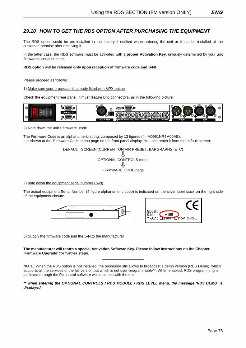
Using the RDS SECTION (FM version ONLY) ENG
Page 76
29.10 HOW TO GET THE RDS OPTION AFTER PURCHASING THE EQUIPMENT The RDS option could be pre-installed in the factory if notified when ordering the unit or it can be installed at the customer’ premise after receiving it. In the latter case, the RDS software must be activated with a proper Activation Key, uniquely determined by your unit firmware's serial number. RDS option will be released only upon reception of firmware code and S-N! Please proceed as follows: 1) Make sure your processor is already fitted with MPX option Check the equipment rear panel: it must feature Bnc connectors, as in the following picture:
2) Note down the unit’s firmware code The Firmware Code is an alphanumeric string, composed by 13 figures (f.i. M0961NR4M00AE). It is shown at the ‘Firmware Code’ menu page on the front panel display. You can reach it from the default screen:
DEFAULT SCREEN (CURRENT ON AIR PRESET, BARGRAPHS, ETC)
OPTIONAL CONTROLS menu
FIRMWARE CODE page
2) note down the equipment serial number (S-N) The actual equipment Serial Number (4 figure alphanumeric code) is indicated on the silver label stuck on the right side of the equipment closure.
3) Supply the firmware code and the S-N to the manufacturer The manufacturer will return a special Activation Software Key. Please follow instructions on the Chapter ‘Firmware Upgrade’ for further steps.
____________________ NOTE: When the RDS option is not installed, the processor still allows to broadcast a demo version (RDS Demo), which supports all the services of the full version but which is not user-programmable**. When enabled, RDS programming is achieved through the Pc control software which comes with the unit. ** when entering the OPTIONAL CONTROLS / RDS MODULE / RDS LEVEL menu, the message ‘RDS DEMO’ is displayed.
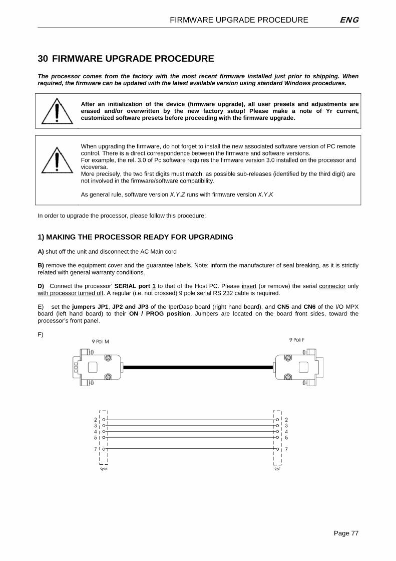
FIRMWARE UPGRADE PROCEDURE ENG
Page 77
30 FIRMWARE UPGRADE PROCEDURE The processor comes from the factory with the most recent firmware installed just prior to shipping. When required, the firmware can be updated with the latest available version using standard Windows procedures.
After an initialization of the device (firmware upgrade), all user presets and adjustments are erased and/or overwritten by the new factory setup! Please make a note of Yr current, customized software presets before proceeding with the firmware upgrade.
When upgrading the firmware, do not forget to install the new associated software version of PC remote control. There is a direct correspondence between the firmware and software versions. For example, the rel. 3.0 of Pc software requires the firmware version 3.0 installed on the processor and viceversa. More precisely, the two first digits must match, as possible sub-releases (identified by the third digit) are not involved in the firmware/software compatibility. As general rule, software version X.Y.Z runs with firmware version X.Y.K
In order to upgrade the processor, please follow this procedure: 1) MAKING THE PROCESSOR READY FOR UPGRADING A) shut off the unit and disconnect the AC Main cord B) remove the equipment cover and the guarantee labels. Note: inform the manufacturer of seal breaking, as it is strictly related with general warranty conditions. D) Connect the processor’ SERIAL port 1 to that of the Host PC. Please insert (or remove) the serial connector only with processor turned off. A regular (i.e. not crossed) 9 pole serial RS 232 cable is required.
E) set the jumpers JP1, JP2 and JP3 of the IperDasp board (right hand board), and CN5 and CN6 of the I/O MPX board (left hand board) to their ON / PROG position. Jumpers are located on the board front sides, toward the processor’s front panel. F)
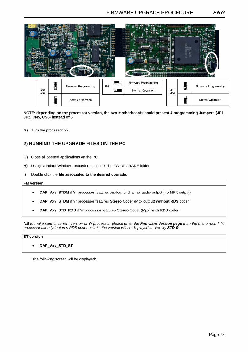
FIRMWARE UPGRADE PROCEDURE ENG
Page 78
NOTE: depending on the processor version, the two motherboards could present 4 programming Jumpers (JP1, JP2, CN5, CN6) instead of 5
G) Turn the processor on. 2) RUNNING THE UPGRADE FILES ON THE PC G) Close all opened applications on the PC. H) Using standard Windows procedures, access the FW UPGRADE folder I) Double click the file associated to the desired upgrade: FM version
• DAP_Vxy_STDM if Yr processor features analog, bi-channel audio output (no MPX output)
• DAP_Vxy_STDM if Yr processor features Stereo Coder (Mpx output) without RDS coder • DAP_Vxy_STD_RDS if Yr processor features Stereo Coder (Mpx) with RDS coder
NB to make sure of current version of Yr processor, please enter the Firmware Version page from the menu root. If Yr processor already features RDS coder built-in, the version will be displayed as Ver: xy STD-R. ST version
• DAP_Vxy_STD_ST
The following screen will be displayed:
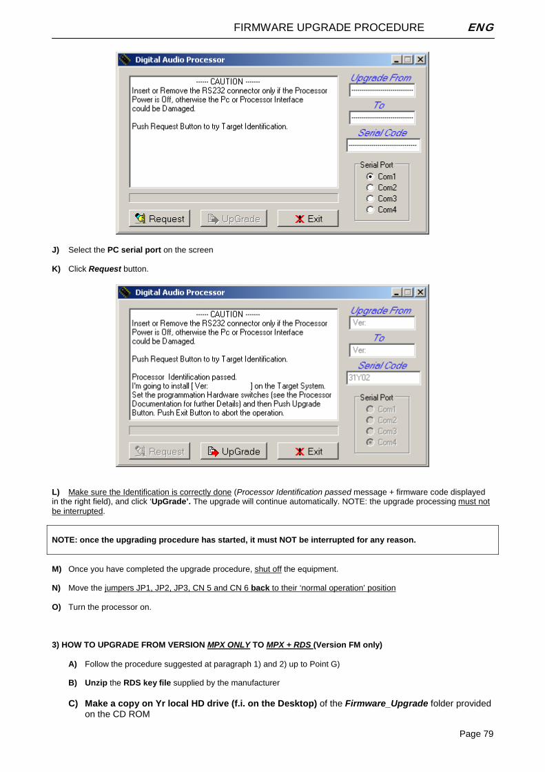
FIRMWARE UPGRADE PROCEDURE ENG
Page 79
J) Select the PC serial port on the screen K) Click Request button.
L) Make sure the Identification is correctly done (Processor Identification passed message + firmware code displayed in the right field), and click ‘UpGrade’. The upgrade will continue automatically. NOTE: the upgrade processing must not be interrupted. NOTE: once the upgrading procedure has started, it must NOT be interrupted for any reason. M) Once you have completed the upgrade procedure, shut off the equipment. N) Move the jumpers JP1, JP2, JP3, CN 5 and CN 6 back to their ‘normal operation’ position O) Turn the processor on. 3) HOW TO UPGRADE FROM VERSION MPX ONLY TO MPX + RDS (Version FM only)
A) Follow the procedure suggested at paragraph 1) and 2) up to Point G) B) Unzip the RDS key file supplied by the manufacturer
C) Make a copy on Yr local HD drive (f.i. on the Desktop) of the Firmware_Upgrade folder provided
on the CD ROM
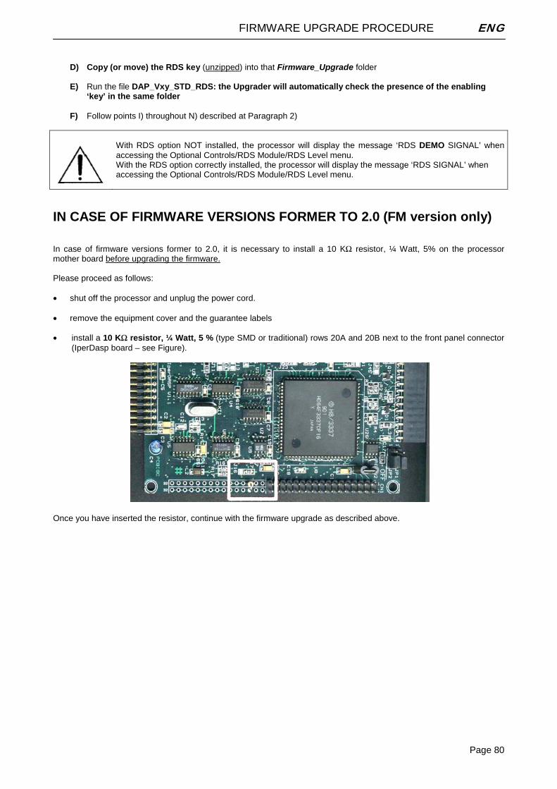
FIRMWARE UPGRADE PROCEDURE ENG
Page 80
D) Copy (or move) the RDS key (unzipped) into that Firmware_Upgrade folder
E) Run the file DAP_Vxy_STD_RDS: the Upgrader will automatically check the presence of the enabling
‘key’ in the same folder
F) Follow points I) throughout N) described at Paragraph 2)
With RDS option NOT installed, the processor will display the message ‘RDS DEMO SIGNAL’ when accessing the Optional Controls/RDS Module/RDS Level menu. With the RDS option correctly installed, the processor will display the message ‘RDS SIGNAL’ when accessing the Optional Controls/RDS Module/RDS Level menu.
IN CASE OF FIRMWARE VERSIONS FORMER TO 2.0 (FM version only) In case of firmware versions former to 2.0, it is necessary to install a 10 KΩ resistor, ¼ Watt, 5% on the processor mother board before upgrading the firmware. Please proceed as follows: • shut off the processor and unplug the power cord. • remove the equipment cover and the guarantee labels • install a 10 KΩ resistor, ¼ Watt, 5 % (type SMD or traditional) rows 20A and 20B next to the front panel connector
(IperDasp board – see Figure).
Once you have inserted the resistor, continue with the firmware upgrade as described above.
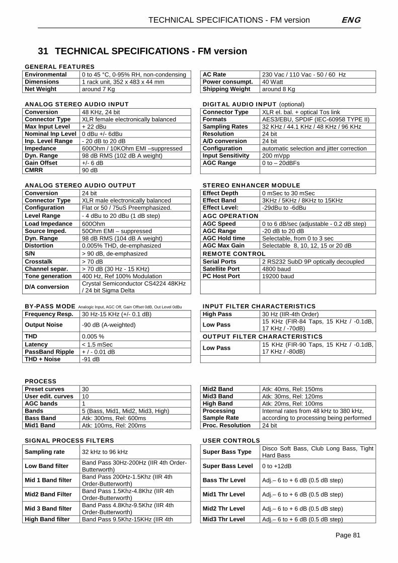
TECHNICAL SPECIFICATIONS - FM version ENG
Page 81
31 TECHNICAL SPECIFICATIONS - FM version
GENERAL FEATURES Environmental 0 to 45 °C, 0-95% RH, non-condensing AC Rate 230 Vac / 110 Vac - 50 / 60 Hz Dimensions 1 rack unit, 352 x 483 x 44 mm Power consumpt. 40 Watt Net Weight around 7 Kg Shipping Weight around 8 Kg
ANALOG STEREO AUDIO INPUT DIGITAL AUDIO INPUT (optional) Conversion 48 KHz, 24 bit Connector Type XLR el. bal. + optical Tos link Connector Type XLR female electronically balanced Formats AES3/EBU, SPDIF (IEC-60958 TYPE II) Max Input Level + 22 dBu Sampling Rates 32 KHz / 44.1 KHz / 48 KHz / 96 KHz Nominal Inp Level 0 dBu +/- 6dBu Resolution 24 bit Inp. Level Range - 20 dB to 20 dB A/D conversion 24 bit Impedance 600Ohm / 10KOhm EMI –suppressed Configuration automatic selection and jitter correction Dyn. Range 98 dB RMS (102 dB A weight) Input Sensitivity 200 mVpp Gain Offset +/- 6 dB AGC Range 0 to – 20dBFs CMRR 90 dB
ANALOG STEREO AUDIO OUTPUT STEREO ENHANCER MODULE Conversion 24 bit Effect Depth 0 mSec to 30 mSec Connector Type XLR male electronically balanced Effect Band 3KHz / 5KHz / 8KHz to 15KHz Configuration Flat or 50 / 75uS Preemphasized. Effect Level: -29dBu to -6dBu Level Range - 4 dBu to 20 dBu (1 dB step) AGC OPERATION Load Impedance 600Ohm AGC Speed 0 to 6 dB/sec (adjustable - 0.2 dB step) Source Imped. 50Ohm EMI – suppressed AGC Range -20 dB to 20 dB Dyn. Range 98 dB RMS (104 dB A weight) AGC Hold time Selectable, from 0 to 3 sec Distortion 0.005% THD, de-emphasized AGC Max Gain Selectable 8, 10, 12, 15 or 20 dB S/N > 90 dB, de-emphasized REMOTE CONTROL Crosstalk > 70 dB Serial Ports 2 RS232 SubD 9P optically decoupled Channel separ. > 70 dB (30 Hz - 15 KHz) Satellite Port 4800 baud Tone generation 400 Hz, Ref 100% Modulation PC Host Port 19200 baud
D/A conversion Crystal Semiconductor CS4224 48KHz / 24 bit Sigma Delta
BY-PASS MODE Analogic Input, AGC Off, Gain Offset 0dB, Out Level 0dBu INPUT FILTER CHARACTERISTICS Frequency Resp. 30 Hz-15 KHz (+/- 0.1 dB) High Pass 30 Hz (IIR-4th Order)
Output Noise -90 dB (A-weighted) Low Pass 15 KHz (FIR-84 Taps, 15 KHz / -0.1dB, 17 KHz / -70dB)
THD 0.005 % OUTPUT FILTER CHARACTERISTICS Latency < 1.5 mSec PassBand Ripple + / - 0.01 dB
Low Pass 15 KHz (FIR-90 Taps, 15 KHz / -0.1dB, 17 KHz / -80dB)
THD + Noise -91 dB
PROCESS Preset curves 30 Mid2 Band Atk: 40ms, Rel: 150ms User edit. curves 10 Mid3 Band Atk: 30ms, Rel: 120ms AGC bands 1 High Band Atk: 20ms, Rel: 100ms Bands 5 (Bass, Mid1, Mid2, Mid3, High) Bass Band Atk: 300ms, Rel: 600ms
Processing Sample Rate
Internal rates from 48 kHz to 380 kHz, according to processing being performed
Mid1 Band Atk: 100ms, Rel: 200ms Proc. Resolution 24 bit
SIGNAL PROCESS FILTERS USER CONTROLS Sampling rate 32 kHz to 96 kHz Super Bass Type Disco Soft Bass, Club Long Bass, Tight
Hard Bass
Low Band filter Band Pass 30Hz-200Hz (IIR 4th Order-Butterworth) Super Bass Level 0 to +12dB
Mid 1 Band filter Band Pass 200Hz-1.5Khz (IIR 4th Order-Butterworth)
Bass Thr Level Adj.– 6 to + 6 dB (0.5 dB step)
Mid2 Band Filter Band Pass 1.5Khz-4.8Khz (IIR 4th Order-Butterworth) Mid1 Thr Level Adj.– 6 to + 6 dB (0.5 dB step)
Mid 3 Band filter Band Pass 4.8Khz-9.5Khz (IIR 4th Order-Butterworth) Mid2 Thr Level Adj.– 6 to + 6 dB (0.5 dB step)
High Band filter Band Pass 9.5Khz-15KHz (IIR 4th Mid3 Thr Level Adj.– 6 to + 6 dB (0.5 dB step)
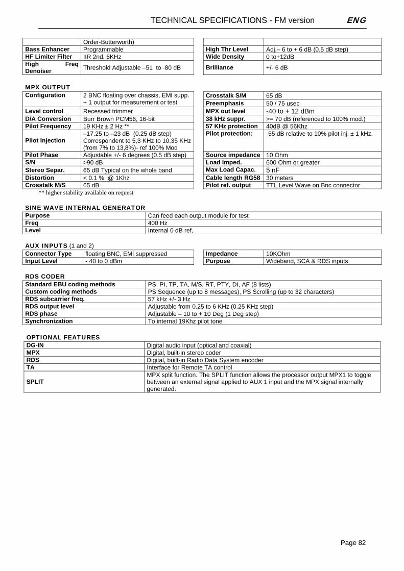
TECHNICAL SPECIFICATIONS - FM version ENG
Page 82
Order-Butterworth) Bass Enhancer Programmable High Thr Level Adj.– 6 to + 6 dB (0.5 dB step) HF Limiter Filter IIR 2nd, 6KHz Wide Density 0 to+12dB High Freq Denoiser Threshold Adjustable –51 to -80 dB Brilliance +/- 6 dB
MPX OUTPUT
Crosstalk S/M 65 dB Configuration 2 BNC floating over chassis, EMI supp. + 1 output for measurement or test Preemphasis 50 / 75 usec
Level control Recessed trimmer MPX out level -40 to + 12 dBm D/A Conversion Burr Brown PCM56, 16-bit 38 kHz suppr. >= 70 dB (referenced to 100% mod.) Pilot Frequency 19 KHz ± 2 Hz ** 57 KHz protection 40dB @ 56Khz
Pilot Injection –17.25 to –23 dB (0.25 dB step) Correspondent to 5,3 KHz to 10,35 KHz (from 7% to 13,8%)- ref 100% Mod
Pilot protection: -55 dB relative to 10% pilot inj, ± 1 kHz.
Pilot Phase Adjustable +/- 6 degrees (0.5 dB step) Source impedance 10 Ohm S/N >90 dB Load Imped. 600 Ohm or greater Stereo Separ. 65 dB Typical on the whole band Max Load Capac. 5 nF Distortion < 0.1 % @ 1Khz Cable length RG58 30 meters Crosstalk M/S 65 dB Pilot ref. output TTL Level Wave on Bnc connector
** higher stability available on request
SINE WAVE INTERNAL GENERATOR Purpose Can feed each output module for test Freq 400 Hz Level Internal 0 dB ref,
AUX INPUTS (1 and 2) Connector Type floating BNC, EMI suppressed Impedance 10KOhm Input Level - 40 to 0 dBm Purpose Wideband, SCA & RDS inputs
RDS CODER Standard EBU coding methods PS, PI, TP, TA, M/S, RT, PTY, DI, AF (8 lists) Custom coding methods PS Sequence (up to 8 messages), PS Scrolling (up to 32 characters) RDS subcarrier freq. 57 kHz +/- 3 Hz RDS output level Adjustable from 0.25 to 6 KHz (0.25 KHz step) RDS phase Adjustable – 10 to + 10 Deg (1 Deg step) Synchronization To internal 19Khz pilot tone
OPTIONAL FEATURES DG-IN Digital audio input (optical and coaxial) MPX Digital, built-in stereo coder RDS Digital, built-in Radio Data System encoder TA Interface for Remote TA control
SPLIT MPX split function. The SPLIT function allows the processor output MPX1 to toggle between an external signal applied to AUX 1 input and the MPX signal internally generated.
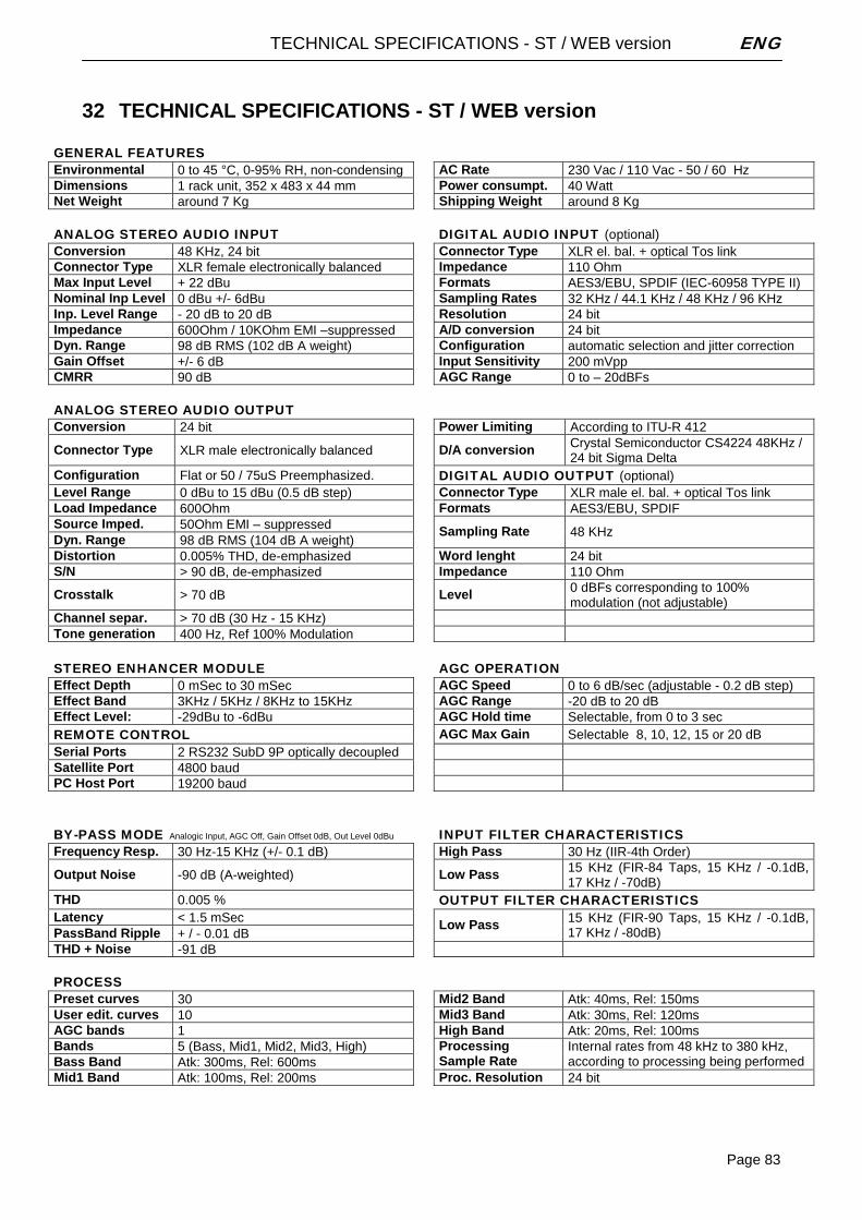
TECHNICAL SPECIFICATIONS - ST / WEB version ENG
Page 83
32 TECHNICAL SPECIFICATIONS - ST / WEB version
GENERAL FEATURES Environmental 0 to 45 °C, 0-95% RH, non-condensing AC Rate 230 Vac / 110 Vac - 50 / 60 Hz Dimensions 1 rack unit, 352 x 483 x 44 mm Power consumpt. 40 Watt Net Weight around 7 Kg Shipping Weight around 8 Kg
ANALOG STEREO AUDIO INPUT DIGITAL AUDIO INPUT (optional) Conversion 48 KHz, 24 bit Connector Type XLR el. bal. + optical Tos link Connector Type XLR female electronically balanced Impedance 110 Ohm Max Input Level + 22 dBu Formats AES3/EBU, SPDIF (IEC-60958 TYPE II) Nominal Inp Level 0 dBu +/- 6dBu Sampling Rates 32 KHz / 44.1 KHz / 48 KHz / 96 KHz Inp. Level Range - 20 dB to 20 dB Resolution 24 bit Impedance 600Ohm / 10KOhm EMI –suppressed A/D conversion 24 bit Dyn. Range 98 dB RMS (102 dB A weight) Configuration automatic selection and jitter correction Gain Offset +/- 6 dB Input Sensitivity 200 mVpp CMRR 90 dB AGC Range 0 to – 20dBFs
ANALOG STEREO AUDIO OUTPUT Conversion 24 bit Power Limiting According to ITU-R 412
Connector Type XLR male electronically balanced D/A conversion Crystal Semiconductor CS4224 48KHz / 24 bit Sigma Delta
Configuration Flat or 50 / 75uS Preemphasized. DIGITAL AUDIO OUTPUT (optional) Level Range 0 dBu to 15 dBu (0.5 dB step) Connector Type XLR male el. bal. + optical Tos link Load Impedance 600Ohm Formats AES3/EBU, SPDIF Source Imped. 50Ohm EMI – suppressed Dyn. Range 98 dB RMS (104 dB A weight)
Sampling Rate 48 KHz
Distortion 0.005% THD, de-emphasized Word lenght 24 bit S/N > 90 dB, de-emphasized Impedance 110 Ohm
Crosstalk > 70 dB Level 0 dBFs corresponding to 100% modulation (not adjustable)
Channel separ. > 70 dB (30 Hz - 15 KHz) Tone generation 400 Hz, Ref 100% Modulation
STEREO ENHANCER MODULE AGC OPERATION Effect Depth 0 mSec to 30 mSec AGC Speed 0 to 6 dB/sec (adjustable - 0.2 dB step) Effect Band 3KHz / 5KHz / 8KHz to 15KHz AGC Range -20 dB to 20 dB Effect Level: -29dBu to -6dBu AGC Hold time Selectable, from 0 to 3 sec REMOTE CONTROL AGC Max Gain Selectable 8, 10, 12, 15 or 20 dB Serial Ports 2 RS232 SubD 9P optically decoupled
Satellite Port 4800 baud PC Host Port 19200 baud
BY-PASS MODE Analogic Input, AGC Off, Gain Offset 0dB, Out Level 0dBu INPUT FILTER CHARACTERISTICS Frequency Resp. 30 Hz-15 KHz (+/- 0.1 dB) High Pass 30 Hz (IIR-4th Order)
Output Noise -90 dB (A-weighted) Low Pass 15 KHz (FIR-84 Taps, 15 KHz / -0.1dB, 17 KHz / -70dB)
THD 0.005 % OUTPUT FILTER CHARACTERISTICS Latency < 1.5 mSec PassBand Ripple + / - 0.01 dB
Low Pass 15 KHz (FIR-90 Taps, 15 KHz / -0.1dB, 17 KHz / -80dB)
THD + Noise -91 dB
PROCESS Preset curves 30 Mid2 Band Atk: 40ms, Rel: 150ms User edit. curves 10 Mid3 Band Atk: 30ms, Rel: 120ms AGC bands 1 High Band Atk: 20ms, Rel: 100ms Bands 5 (Bass, Mid1, Mid2, Mid3, High) Bass Band Atk: 300ms, Rel: 600ms
Processing Sample Rate
Internal rates from 48 kHz to 380 kHz, according to processing being performed
Mid1 Band Atk: 100ms, Rel: 200ms Proc. Resolution 24 bit
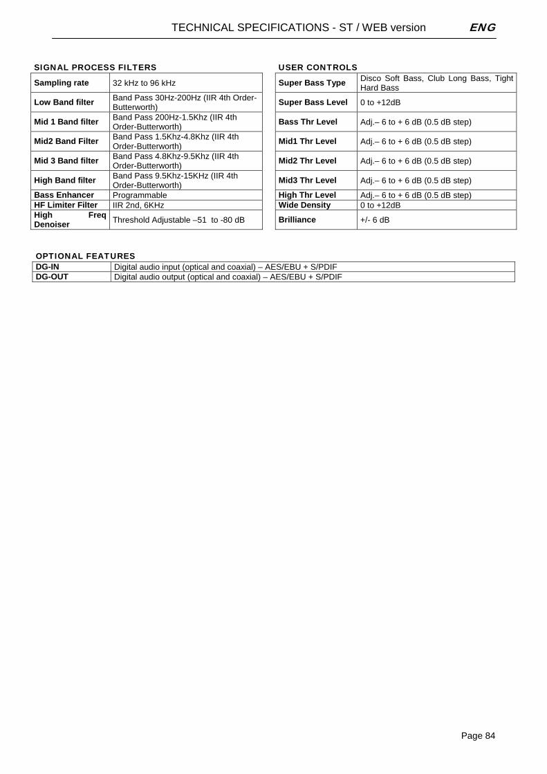
TECHNICAL SPECIFICATIONS - ST / WEB version ENG
Page 84
SIGNAL PROCESS FILTERS USER CONTROLS
Sampling rate 32 kHz to 96 kHz Super Bass Type Disco Soft Bass, Club Long Bass, Tight Hard Bass
Low Band filter Band Pass 30Hz-200Hz (IIR 4th Order-Butterworth) Super Bass Level 0 to +12dB
Mid 1 Band filter Band Pass 200Hz-1.5Khz (IIR 4th Order-Butterworth) Bass Thr Level Adj.– 6 to + 6 dB (0.5 dB step)
Mid2 Band Filter Band Pass 1.5Khz-4.8Khz (IIR 4th Order-Butterworth)
Mid1 Thr Level Adj.– 6 to + 6 dB (0.5 dB step)
Mid 3 Band filter Band Pass 4.8Khz-9.5Khz (IIR 4th Order-Butterworth) Mid2 Thr Level Adj.– 6 to + 6 dB (0.5 dB step)
High Band filter Band Pass 9.5Khz-15KHz (IIR 4th Order-Butterworth) Mid3 Thr Level Adj.– 6 to + 6 dB (0.5 dB step)
Bass Enhancer Programmable High Thr Level Adj.– 6 to + 6 dB (0.5 dB step) HF Limiter Filter IIR 2nd, 6KHz Wide Density 0 to +12dB High Freq Denoiser Threshold Adjustable –51 to -80 dB Brilliance +/- 6 dB
OPTIONAL FEATURES DG-IN Digital audio input (optical and coaxial) – AES/EBU + S/PDIF DG-OUT Digital audio output (optical and coaxial) – AES/EBU + S/PDIF
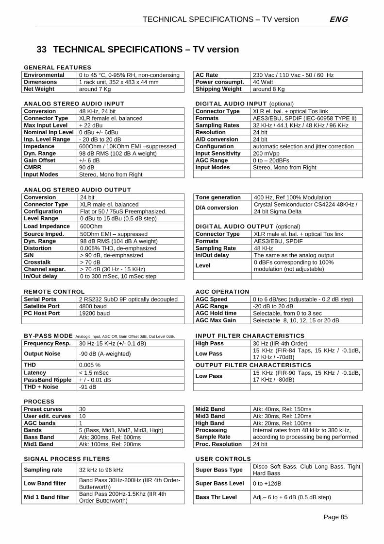
TECHNICAL SPECIFICATIONS – TV version ENG
Page 85
33 TECHNICAL SPECIFICATIONS – TV version
GENERAL FEATURES Environmental 0 to 45 °C, 0-95% RH, non-condensing AC Rate 230 Vac / 110 Vac - 50 / 60 Hz Dimensions 1 rack unit, 352 x 483 x 44 mm Power consumpt. 40 Watt Net Weight around 7 Kg Shipping Weight around 8 Kg
ANALOG STEREO AUDIO INPUT DIGITAL AUDIO INPUT (optional) Conversion 48 KHz, 24 bit Connector Type XLR el. bal. + optical Tos link Connector Type XLR female el. balanced Formats AES3/EBU, SPDIF (IEC-60958 TYPE II) Max Input Level + 22 dBu Sampling Rates 32 KHz / 44.1 KHz / 48 KHz / 96 KHz Nominal Inp Level 0 dBu +/- 6dBu Resolution 24 bit Inp. Level Range - 20 dB to 20 dB A/D conversion 24 bit Impedance 600Ohm / 10KOhm EMI –suppressed Configuration automatic selection and jitter correction Dyn. Range 98 dB RMS (102 dB A weight) Input Sensitivity 200 mVpp Gain Offset +/- 6 dB AGC Range 0 to – 20dBFs CMRR 90 dB Input Modes Stereo, Mono from Right Input Modes Stereo, Mono from Right
ANALOG STEREO AUDIO OUTPUT Conversion 24 bit Tone generation 400 Hz, Ref 100% Modulation Connector Type XLR male el. balanced Crystal Semiconductor CS4224 48KHz / Configuration Flat or 50 / 75uS Preemphasized.
D/A conversion 24 bit Sigma Delta
Level Range 0 dBu to 15 dBu (0.5 dB step) Load Impedance 600Ohm DIGITAL AUDIO OUTPUT (optional) Source Imped. 50Ohm EMI – suppressed Connector Type XLR male el. bal. + optical Tos link Dyn. Range 98 dB RMS (104 dB A weight)
Formats AES3/EBU, SPDIF
Distortion 0.005% THD, de-emphasized Sampling Rate 48 KHz S/N > 90 dB, de-emphasized In/Out delay The same as the analog output Crosstalk > 70 dB Channel separ. > 70 dB (30 Hz - 15 KHz)
Level 0 dBFs corresponding to 100% modulation (not adjustable)
In/Out delay 0 to 300 mSec, 10 mSec step
REMOTE CONTROL AGC OPERATION Serial Ports 2 RS232 SubD 9P optically decoupled AGC Speed 0 to 6 dB/sec (adjustable - 0.2 dB step) Satellite Port 4800 baud AGC Range -20 dB to 20 dB PC Host Port 19200 baud AGC Hold time Selectable, from 0 to 3 sec AGC Max Gain Selectable 8, 10, 12, 15 or 20 dB
BY-PASS MODE Analogic Input, AGC Off, Gain Offset 0dB, Out Level 0dBu INPUT FILTER CHARACTERISTICS Frequency Resp. 30 Hz-15 KHz (+/- 0.1 dB) High Pass 30 Hz (IIR-4th Order)
Output Noise -90 dB (A-weighted) Low Pass 15 KHz (FIR-84 Taps, 15 KHz / -0.1dB, 17 KHz / -70dB)
THD 0.005 % OUTPUT FILTER CHARACTERISTICS Latency < 1.5 mSec PassBand Ripple + / - 0.01 dB
Low Pass 15 KHz (FIR-90 Taps, 15 KHz / -0.1dB, 17 KHz / -80dB)
THD + Noise -91 dB
PROCESS Preset curves 30 Mid2 Band Atk: 40ms, Rel: 150ms User edit. curves 10 Mid3 Band Atk: 30ms, Rel: 120ms AGC bands 1 High Band Atk: 20ms, Rel: 100ms Bands 5 (Bass, Mid1, Mid2, Mid3, High) Bass Band Atk: 300ms, Rel: 600ms
Processing Sample Rate
Internal rates from 48 kHz to 380 kHz, according to processing being performed
Mid1 Band Atk: 100ms, Rel: 200ms Proc. Resolution 24 bit
SIGNAL PROCESS FILTERS USER CONTROLS
Sampling rate 32 kHz to 96 kHz Super Bass Type Disco Soft Bass, Club Long Bass, Tight Hard Bass
Low Band filter Band Pass 30Hz-200Hz (IIR 4th Order-Butterworth)
Super Bass Level 0 to +12dB
Mid 1 Band filter Band Pass 200Hz-1.5Khz (IIR 4th Order-Butterworth) Bass Thr Level Adj.– 6 to + 6 dB (0.5 dB step)

WARRANTY ENG
Page 86
Mid2 Band Filter Band Pass 1.5Khz-4.8Khz (IIR 4th Order-Butterworth)
Mid1 Thr Level Adj.– 6 to + 6 dB (0.5 dB step)
Mid 3 Band filter Band Pass 4.8Khz-9.5Khz (IIR 4th Order-Butterworth) Mid2 Thr Level Adj.– 6 to + 6 dB (0.5 dB step)
High Band filter Band Pass 9.5Khz-15KHz (IIR 4th Order-Butterworth) Mid3 Thr Level Adj.– 6 to + 6 dB (0.5 dB step)
Bass Enhancer Programmable High Thr Level Adj.– 6 to + 6 dB (0.5 dB step) HF Limiter Filter IIR 2nd, 6KHz Wide Density 0 to +12dB HiFreq Denoiser Threshold Adjustable –51 to -80 dB Brilliance +/- 6 dB
OPTIONAL FEATURES DG-IN Digital audio input (optical and coaxial) – AES/EBU + S/PDIF DG-OUT Digital audio output (optical and coaxial) – AES/EBU + S/PDIF
34 WARRANTY The manufacturer offers a 1-year ex works warranty. Do not open the equipment. The warranty shall be voided if any of the warranty seals are broken. The manufacturer shall not be liable for damage of any kind deriving from or in relation to incorrect use of the product.