Embed Size (px)
Citation preview
1
FAMU-FSU College of Engineering Department of Mechanical Engineering
Final Design Report
EEL4911C/EML4511C– ECE/ME Senior Design Project I Team #: 21 Student team members ! Santiago Franco, mechanical engineering (Email: [email protected]) ! Darryl McGowan, electrical engineering (Email: [email protected]) ! Kyle Miller, mechanical engineering (Email: [email protected]) ! Sondra Miller, electrical engineering (Email: [email protected]) ! Gregory Robertson, mechanical engineering (Email: [email protected]) ! Stuart Royal, mechanical engineering (Email: [email protected]) ! Alex Smith, electrical engineering (Email: [email protected]) Senior Design Project Instructor: Dr. Kamal Amin Lead Technical Advisor: Dr. Jonathan Clark Electrical Senior Design Project Instructor: Dr. Michael Frank Electrical Technical Advisor: Dr. Bruce Harvey
Submitted in partial fulfillment of the requirements for EML4511C – ME Senior Design Project I EEL4911C – ECE Senior Design Project I
December 6, 2012

2
Executive Summary The main objective of the FAMU-FSU 2012-2013 RoboSub Team is to participate in the AUVSI
Foundation and ONR's 15th International RoboSub Competition. The competition is held in the TRANSDEC pool in San Diego, California and consists of a practice round, a first round, and a final round. Before the competition begins, each AUV (Autonomous Underwater Vehicle) will be inspected by the judges of the AUV competition to make sure that they do not pose a serious risk to TRANSDEC, other competitors, or the swimmers following the AUV. The judges will also be checking that the AUV is within the size, weight, and density restrictions that have been set forth. Once the AUV has been cleared by the judges they will then allow the AUV to compete in the competition.
The current design was conceived with the aim of developing a robust and flexible system. It achieves this through simplicity. The hull that will contain the electronics is a rectangular box with a lid affixed with bolts. The frame is both lightweight and functional as it uses a minimal number of parts and does not obstruct the lid, but still has enough mounting points for all necessary thrusters, sensors, and actuators. In addition, the new mechanical design will only incorporate five thrusters instead of six while still maintaining a similar level of control. These alterations combine to produce a lighter and more accessible design. With regards to the electronics, we have greatly simplified the power system. The new design utilizes a separate battery for each major electronic subsystem, eliminating many issues with voltage regulation that were present in the previous design. Much of the hardware has been replaced: there is a new PC, and the Arduino Unos will be accompanied by an Arduino Mega which will control all AUV motions. The Arduino Mega controlling the thrusters will allow the AUV to maintain constant balance in conjunction with an inertial measurement unit (IMU). This year’s design was designed with longevity in mind. A robust and well-documented vehicle will not only provide a better chance of being ready for the upcoming presentation, but will be more suitable for modification and improvement in future years.

3
Table of Contents
Executive Summary Table of Contents 1 Introduction
1.1 Acknowledgements 1.2 Problem Statement 1.3 Operating Environment 1.4 Intended Use(s) and Intended User(s) 1.5 Assumptions and Limitations 1.6 Expected End Product and Other Deliverables 1.7 Safety Precautions 1.8 Environmental Concerns 2.1 Overview of the System 2.2 Major Components of the System
2.2.1 Power System 2.2.2 Electronics 2.2.3 Software System
2.3 Subsystem Requirements 2.3.1 Voltage Regulation 2.3.2 Main Processing Unit (MPU) 2.3.3 Arduino UNO 2.3.4 Arduino Mega 2.3.5 Inertial Measurement Unit 2.3.6 Motor Controller 2.3.7 Vision System 2.3.8 Air Release Actuators 2.3.9 Computer Vision 2.3.10 Movement Controller 2.3.11 Self-Positioning System 2.3.12 Task Completion System
2.4 Performance Assessment 2.4.1 Required Capabilities Assessment
2.5 Design Process 2.6 Overall Risk Assessment
3 Design of Major Components 3.1 Power System
3.3.1 Top Level Control Module 3.3.2 Vision System
3.4 Electronics Housing 3.6 Anything Else(Mechanical Components?)???
4 Test Plan 4.1 System and Integration Test Plan

4
4.2 Test Plan for Major Components 4.2.1 <title of block 1> 4.2.2 <title of block 2> 4.2.3 Software System Test Plan
4.2.3.1 Top Level Control Module Test Plan 4.3 Summary of Test Plan Status
5 Schedule 6 Budget Estimate 7 Conclusion 8 References Appendices (optional)

5
1 Introduction As time has passed the Robosub senior design team has covered much ground in completing tasks to reach its final goal of having a working AUV for the AUVSI RoboSub Competition. Following the most recent competition rules that are posted on the AUVSI website, the team has created plans for an AUV that will be able to operate and succeed within the competition guidelines. A new electronics housing and framing structure has been designed and is currently on path to creation. A detailed electronics system has been designed to handle the communication of tasks among components. Vision software has been chosen, installed, and is currently being worked with to use it to its maximum potential. The electronics system and mechanical components are being supported by a sufficient power system. Several of the mechanical and electrical components have been tested and confirmed of their functionality. Risks involved in the project have been taken into consideration and much has been done to avoid possible pitfalls. Scheduling for the project requires much more work to be done in the spring semester in order to have a working product to compete with.
1.1 Acknowledgements
The 2012-2013 FAMU-FSU RoboSub team would like to acknowledge the following individuals for their continuing contributions to the project:
" Dr. Shih for providing funding via the Naval Engineering Education Center to complete this project.
" Dr. Jonathan Clark for advising the team on technical details, as well as advising on effective presentations and reviewing the team's written documents.
" Dr. Harvey for advising the team on technical details, as well as reviewing written documents for the team.
" FAMU- FSU COE Stride Lab for providing working and storage room in its lab. " Dr. Frank for instruction on how to present effectively and create thorough written documents,
and technical details. " Ryan Kopinsky for information regarding components and software from last year.
1.2 Problem Statement The current design team inherited a project that had some functionality but still needed significant modifications. The hull for the electronics served its purpose, but it was extremely complicated and time consuming to access. The frame on which the hull and the components were mounted proved to be unbalanced which affected the navigation of the robot in the water. The overall weight of the vehicle was also several pounds over the target weight. The functional software for the design was limited to a demonstration which made the vehicle submerge and move around in a predetermined manner. This code was effectively unusable for the current team, because it lacked the structural support for the artificial intelligence necessary for the competition. This year, the team aims to redesign many of the AUV's

6
components and software for robustness and to address the programmatic requirements of the competition.
To address the issue of the hull, a new one will be designed, giving ease of access higher priority than in previous years. The main focus of the hull design will still be the waterproofing and pressure bearing aspects, but this will be designed around a different method of disassembly which prioritizes simplicity and minimal interaction with the mounted components. To have a more balanced, lightweight frame, the components will be relocated and the layout of the 80/20 aluminum that is being used will be changed. A new software design will be developed and implemented such that it provides the decision making, image processing, and motion control capabilities that are needed for the robot to compete successfully.
1.3 Operating Environment The AUV will operate submerged in a saltwater pool at the TRANSDEC facility in San Diego.
The TRANSDEC facility is a 300 ft by 200 ft by 38 ft deep pool containing 6 million gallons of chemically treated salt water which will be comparable to oceanic conditions. The temperature of the pool is isothermally maintained and should therefore should not adversely affect the performance of the AUV. The pool will be still and should have no waves disrupting the movement of the vehicle. The clarity of the water in the pool is anticipated to be excellent for camera and vision equipment. However, TRANSDEC is an outdoor facility, so adverse weather conditions may be a possibility during competition.
A hazardous environment will exist during transportation of the AUV to the TRANSDEC facility in San Diego in which it will have to be shipped in a 6 ft by 6 ft by 3 ft box. A support sling will be constructed to properly secure the AUV to prevent and minimize damage during transport and while being lowered into the competition pool.
Testing of the AUV will take place at the Morcom Aquatics Center pool at the Florida State University. The Morcom pool is chlorinated fresh water, which is less dense than salt water. As a result, the AUV will be less buoyant during testing than it will be during the competition.
1.4 Intended Use(s) and Intended User(s) The intended use for the AUV is to compete in the annual RoboSub competition hosted by the Association for Unmanned Vehicle Systems Integration (AUVSI) and United States Office of Naval Research (ONR). The competition will consist of the AUV submerging, passing through a gate, following a obstacle course, dropping markers into specified containers, shooting torpedoes into specified targets, grab an object from the floor of the pool, carry it up and surface into a designated area then drop the object. These tasks are based on the information that is currently available and the only tasks that will be designed for at the current time. This is subject to change pending the release of the rules for the 2013 competition.
The AUV is autonomous, so the users will only be working to program and build the AUV before the competition, and it will operate by itself during the competition. The intended users of the AUV are the

7
team members who built it, and possibly future team members who become involved with the project later. All users are expected to have an in-depth understanding of the required engineering principles to understand the design of the AUV.
In addition, the vehicle will be closely followed by AUVSI divers to ensure safety of the vehicle and the TRANSDEC facility. As such, the AUV must incorporate certain features to ensure the safety of these divers. These safety features will be discussed in detail later in this report.
1.5 Assumptions and Limitations The electronics housing will be made of 6064 aluminum in the shape of a box with a clear
polycarbonate lid. The aluminum sides and base plate and the polycarbonate cover will allow for observation of the electronics housing without necessitating disassembly. The housing will be made watertight through the use of a groove cut into the polycarbonate cover and an O-ring placed inside that slips onto the aluminum plate walls. A total of 12 bolts will be drilled through the edge of the polycarbonate lid and edge of the box, firmly forming a tight seal around the perimeter of the lid.
There will be only one electronics housing for the AUV. The outer frame will be made from the 80/20 inch solid aluminum T-slots used in the previous RoboSub. The cameras, marker dropper, claw, torpedoes, compressed air tank, thrusters, batteries, and actuators will be used from the previous year’s sub. These components will be bolted to the frame and water sealed properly.
For power distribution to the various electrical systems, off-the-shelf voltage regulators will be used and the electronics housing will be large enough to include all batteries required. For all tasks that require implementation of intelligence, it has been assumed that the mission will be similar to that of last year. Until new rules for the contest have been received, intelligence to complete the 2012 mission will be implemented.
Due to the fact that the 2013 have not yet been released, the 2012 rules have been assumed to be representative of the 2013 competition. This assumption will guide many of the design criteria until the rules for the upcoming competition are released. The primary size requirements are the following: the weight must be under 125 lbs or immediate disqualification will occur, the robot must be fully autonomous, and the robot must not exceed 6 feet by 3 feet by 3 feet. The AUV must be able to complete all challenges within a 10-minute time limit. Additional limitations apply in the form of time constraints imposed by the senior design course schedule and budget limitation due to limited funding sources.
1.6 Expected End Product and Other Deliverables The end product of this project should be a completely autonomous unmanned submersible
vehicle. It should be capable of submerging, entering through a gate, following a obstacle course via colored paths, dropping markers into specified containers, shoot torpedoes into specified targets, grab a specified object from the floor of the pool, carry it up and surface into a designated area then drop the
8
object. This project’s deliverable, the AUV, is a competition based product and is only being designed to complete these predetermined tasks.
Other expected products of the AUVSI RoboSub competition are a team website, a journal paper, and an introductory video of the team. The team website should consist of a layout of the team’s work in building the AUV that is accessible to the public. The journal paper should be a technical paper explaining the operations of the team’s AUV. The introductory video should be a short and riveting video to introduce the team and their competing AUV. Dates at which time these items are required is set by the competition rules, which unfortunately have not been released by the time of this writing. The only working date is July 22-28, 2013, which is when the competition is scheduled to take place.
1.7 Safety Precautions Proper safety precautions must be taken when designing and building any engineering project.
The AUVSI competition rules set some safety standards for all competing AUV’s. Each AUV must have an emergency kill switch that is easily accessible to the surrounding divers following the AUV. This is to ensure that the judges can power down the AUV at will. For the torpedo system, AUVSI requires that the torpedo launchers fire their payload at a low enough impact rate to not cause bruising on a person. Safety shrouds covering the blades on all the thrusters to ensure the blades cannot harm the divers following the AUV.
To ensure the safety of the components inside the electronics housing, several things were done. A rigid exterior frame and hull made of strong aluminum will withstand any minor force that the AUV could encounter. Along the lid of the housing, a watertight O-ring firmly creates a barrier stopping water from entering. Finally, separating each power system as a last precaution will allow only sectional damage if water does enter the housing.
1.8 Environmental Concerns Environmental impact is concern that must be planned for and minimized in any scenario. The AUV will have standard, non-toxic aluminum for the hull and housing. The sealants used around the secant holes are also non-toxic to the environment. Proper care must be taken to properly dispose of the batteries used to power the AUV. During the duration of this team’s involvement with the AUV these batteries will still be usable; however, in the future years senior design teams must properly dispose of the batteries. When the aluminum parts of the project are no longer needed, they need to be properly recycled at an appropriate facility.
2 System Design The following section will discuss the various subsystems and components of this year’s design
and how they will work together to achieve project goals. The chosen design emphasizes robustness, flexibility, and simplicity and seeks to eliminate issues with the previous model with a nearly complete redesign of all systems. Major changes from last year’s design include an entirely new hull and frame

9
with an unobstructed lid for easy access, individual power networks for each electrical subsystem, and a more integrated control system. These changes allow the new design to achieve all design goals while reducing weight and complexity.
2.1 Overview of the System The primary criterion of the mechanical design was the development of a reliable housing for
electronics as well as mounting points for all other components that are needed to accomplish the tasks that will be set for the competition. See figure 1 for the CAD model of what was developed and hope to have built before the end of 2012. The main components that will be needed for the completion of the physical design have already been developed or bought by last year’s team. These includes the thrusters, torpedo launchers, claw attachment, marker dropper, cameras and their waterproof cases, the actuators used to control the claw and torpedoes, and the 80/20 aluminum that makes up the body of the frame. The electronics hull is a completely new design compared to last year’s team and improves on many faults that design had. These issues will be discussed in later sections.
Figure 1. CAD model of final design
The main parts of the electrical subsystem are the top level controller, vision system, and the electronics hardware. The computer vision will make use of an open source vision software called OpenCV. This software will allow the computer to recognize different shapes and colors that the camera picks up using a database that can be expanded for the uncommon/specific shapes that we will need for the competition. To make it easier for the computer to communicate with OpenCV, Robot Operating System (ROS) will be used. It has a built-in support for OpenCV and common robotics capabilities.
The top level controller will be in charge of the decision making of the AUV. This will be done through a state machine. Each task will be a state with sub-state to control individual actions of the AUV during each task. The state machine will be developed using the rules from last years competition until the new rules have been released.

10
The electronics hardware will be an integral part of the AUV. The main components of the electronics hardware will be 3 Arduino Unos, an Arduino Mega, and a mini-PC running Ubuntu 12.04 Linux.
2.2 Major Components of the System
2.2.1 Power System Each controller, sensor, actuator, and thruster requires a specific voltage and current to function.
To achieve this, a power system has to be designed with the idea that it must be operated remotely; batteries will be required. Table 1 is a simple chart which shows some of the requirements needed for selected components of the AUV.
Component Maximum Current Consumption Average Current Consumption
Zotac PC Board 3.5A 1.5A
Arduino(s) .75A .5A
IMU .075A .060A
Thrusters 12A 3A
Table 1. Current consumption of electrical devices.
Figure 2. Block diagram of power supply to thrusters
11
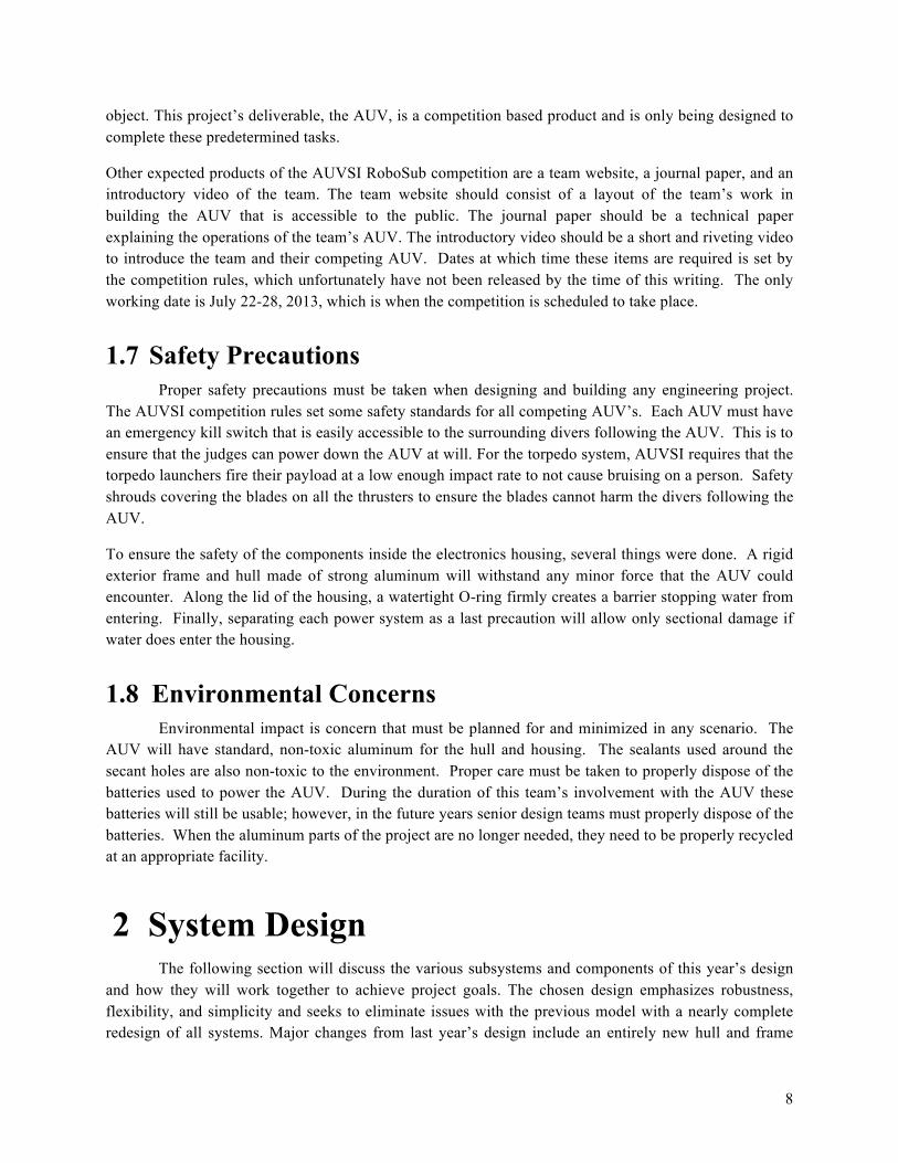
Figure 3. Block diagram of power supply to CPU and components
Figure 4. Block diagram of power supply to actuators
2.2.2 Electronics The hardware required to control the AUV is comprised of a main control unit and many
subsystems. Each subsystem is an entity within itself that is self-sustaining except for instruction from the main unit. Below is a basic block diagram illustrating how the electronics communicate with each other and other subsystems.

12
Figure 5. A simple block diagram of the proposed electronics system.
2.2.3 Software System The software system will be composed of three distinct modules that perform the required tasks,
and potentially a fourth module which will be responsible for checking the work of the other three modules. Figure 6 shows the general layout of each of the components, and each component is described in detail in the subsequent sections.
Figure 6. A simple block diagram of the proposed software system with its interactions with external
systems indicated by dashed lines.
2.2.3.1 Top-Level Control Module

13
The top-level control module is the software system that will perform the overall task management of the sub. This module is the implementation top-level Mealy finite-state machine (FSM) that will instruct other system modules based on the current state of the sub, namely, the input from its sensors. Leveraging the apriori knowledge of the order of occurrence of tasks at the competition, a FSM can be designed that has the necessary number and order of states to satisfy the tasks.
The current design uses nested state machines. An outer level FSM will keep track of which task the AUV is currently perform and the next task. An inner level FSM will keep track of the primitive tasks that must occur during each task. Figure 7 illustrates this point.
Figure 7. Nested state machine diagram. Blue represents outer FSM while green represents inner level FSMs.
Now that algorithm development for this module has been completed, these FSMs can now be implemented.
2.2.3.2 Vision System The vision system is the software module that satisfies all of the necessary image processing
needs of the AUV. Modules from this system will be called when needed by the top-level control software. Written using OpenCV, this module will implement object recognition, a frequently occurring problem in the contest.
The vision module will have a list of functions that correspond to each task. For example, at the buoy task, the AUV must identify circular objects of varying colors. A vision function will be generated that accomplishes this and sends its results to the top level for decision making. Analogous functions will be developed for other primitive actions found within each task.
2.2.4 Electronics Housing (Hull)
The main design criterion behind the design of the electronics housing is the size. The size is an important factor in that it must be large enough to hold all the electronics hardware while having a minimal amount of free space. Free space will decrease the overall density of the vehicle, making it more

14
positively buoyant than is desired. Also as little aluminum as possible should be used to reduce weight since one of the main restrictions in the competition is weight.
The electronics housing is an important factor in the AUV since it will be housing all of our electronic hardware and will need to be watertight to prevent water shorting the electronics. The waterproofing will be done by using an O-ring in a channel that will be cut using a CNC machine into the top part of the box. This will be clamped down by adding a flange onto the upper part of the walls, creating a lip, which would then be used to bolt the top lid down creating a tight seal. The original plan to hold the watertight seals was attaching clamps instead of using bolts to hold the lid in place. After conversing with the machine shop, it was discovered that the machining of the attachment needed to hold the clamps in place, along with the number of clamps that would be needed would be far more expensive and time consuming as it would be to attach the flange and bolt it down.
The housing is also important in that it is the main medium through which the heat generated by the electronics will be dissipated. If the heat dissipated is not enough, then the electronics could overheat, which could then cause small problems, such as warping the boards, to large problems, such as completely destroying the board. The dissipation of the heat is the main design parameter that went into our choice of aluminum as the main body of the electronics housing. The use of aluminum, however, is not enough to dissipate the heat generated by the electronics and so the addition of cooling fans will be needed inside of the electronics housing to generate sufficient extraction.
Figure 8. CAD model of Hull 2.2.5 Frame Structure
Arranging the components, such as the cameras, torpedoes, etc. , in a balanced manner will be crucial to the success of the robot. For the computer to only worry about the motion of the robot and not its tilt, everything must be arranged in such a manner that the submarine will not have a tendency to lean in any particular way. Once the hull for the electronics is finalized, the new frame will be put together
15
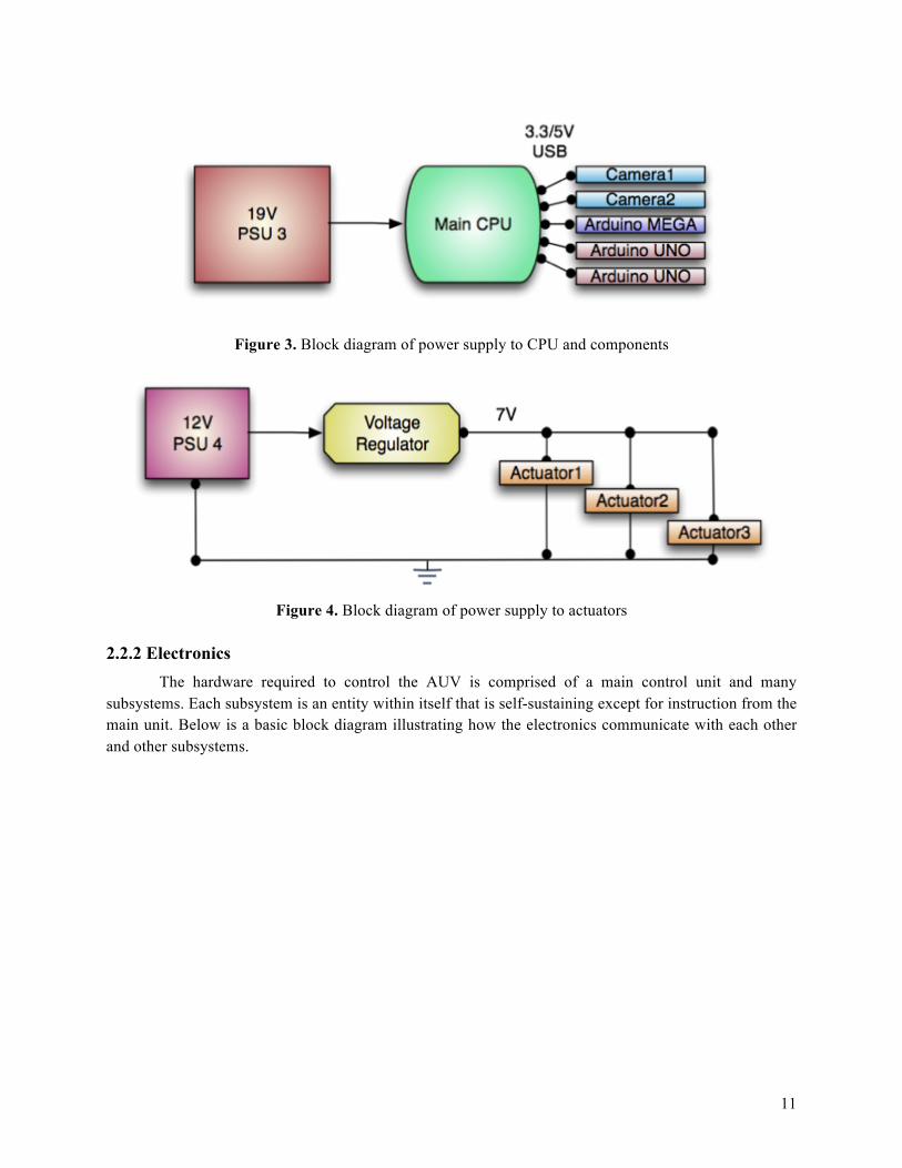
around it. The external components will then be placed in key locations based on the center of mass of the hull and frame together. An image of the frame structure can be seen in Figure 9.
Figure 9. CAD model of framework and components
2.3 Subsystem Requirements Each device has specifications regarding power requirements, signal protocol, placement, orientation, function, and design. Throughout this section you will find details about each chosen device and why it was chosen for the AUV.
2.3.1 Voltage Regulation Many of the devices used on the AUV require different voltages. This will be accomplished in
two ways: first by using three different battery sources, and secondly by using voltage regulators to step down or step up voltages to individual devices as necessary. For simplicity, the team has designed the power system such that only one battery network will require voltage regulation: the 12V battery system. Many of the components of the system, such as the Arduinos, require 5V supplies. To achieve this, the high-efficiency Pololu step-down voltage regulator has been chosen. Pololu Step-Down Voltage Regulator D15V35F5S3:
" Input voltage: 4.5 V to 24 V " Typical continuous output current: 3.5 A (Actual continuous output current depends on thermal
dissipation.) " Output voltage selectable as 5 V or 3.3 V " 700 kHz switching frequency
16
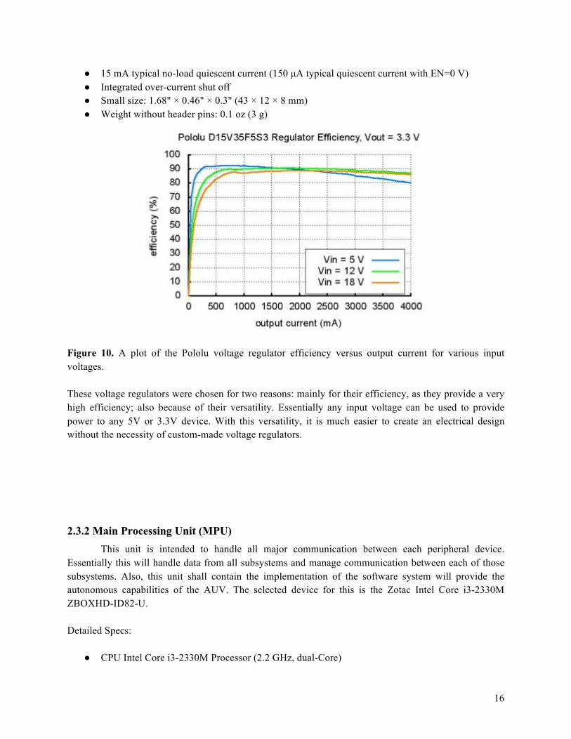
" 15 mA typical no-load quiescent current (150 µA typical quiescent current with EN=0 V) " Integrated over-current shut off " Small size: 1.68" # 0.46" # 0.3" (43 # 12 # 8 mm) " Weight without header pins: 0.1 oz (3 g)
Figure 10. A plot of the Pololu voltage regulator efficiency versus output current for various input voltages. These voltage regulators were chosen for two reasons: mainly for their efficiency, as they provide a very high efficiency; also because of their versatility. Essentially any input voltage can be used to provide power to any 5V or 3.3V device. With this versatility, it is much easier to create an electrical design without the necessity of custom-made voltage regulators.
2.3.2 Main Processing Unit (MPU) This unit is intended to handle all major communication between each peripheral device.
Essentially this will handle data from all subsystems and manage communication between each of those subsystems. Also, this unit shall contain the implementation of the software system will provide the autonomous capabilities of the AUV. The selected device for this is the Zotac Intel Core i3-2330M ZBOXHD-ID82-U. Detailed Specs:
" CPU Intel Core i3-2330M Processor (2.2 GHz, dual-Core)

17
" Chipset Intel HM65 Express " Memory:2 X 204- pin DDR3-1333 SODIMM Slots, Max Capacity of 16GB " Hard Drive: Supports 1 X 2.5-Inch SATA 6.0 GB/s Hard Drive " Ports: 4 X USB 2.0 Ports (1 front, 2 rear, 1 top); 2 X USB 3.0 Ports; 1 X Wi-Fi Antenna
Connector; 1 X DVI Port; 1 X HDMI Port; 1x?Optical S/PDIF Out; 1 X RJ45 LAN Port; Audio I/O Jacks
" Carder Reader: 6-In-1 Card Reader, Supports MMC/ SD/ SDHC/ MS/ MS Pro/ xD " LAN: Integrated Gigabit Ethernet Controller; 802.11n/g/b Wireless LAN; Bluetooth 3.0
Choosing a main control system is one of the most important tasks in designing the AUV. It must be able to handle bidirectional communication between multiple devices, interpret image data through the vision system, calculate algorithms, top level control, and also provide a stable system to operate. Many factors went into selecting a unit that can handle all of these tasks: Heat dissipation, power consumption, size, communication ports, price, and functionality.
" The Intel i3 mobile processor is more than enough processing power for AUV tasks " Produces minimal heat, thus it has a great power-to-heat ratio " Contains 6 USB ports which is necessary for all intended devices " Requires a simple laptop battery instead of a regulated voltage system " Ease of use and assembly.
2.3.3 Arduino UNO Each serial device needs a “bridge” to communicate with the MPU. The Arduino UNO is a perfect solution to handle this communication. Each Arduino will control a peripheral: actuators, hydrophones, etc. This will take the serial communication from each subsystem and allow control over USB from the MPU.
" Operating Voltage : 5V " Input Voltage : 7-12V " Digital I/O Pins : 14 (6 Provide PWM output) " Analog Input Pins: 6 " DC Current per I/O pin: 40mA " DC Current for 3.3V Pin: 50mA " Flash Memory: 32KB " SRAM: 2KB " EEPROM: 1KB " Clock Speed: 16MHz
The greatest advantage of using an Arduino is its versatility. Each Arduino will have its own subsystem process. This will allow that subsystem to be controlled by the Arduino, without always needing outside assistance from the MPU. This will take processing power off of the MPU and decrease unnecessary communication between devices.

18
Figure 11. Arduino Uno board
2.3.4 Arduino Mega This device was selected to be specifically used for motor control. It contains more pins to be
used with all six thrusters. This allows thruster control to be sent to only one device instead of multiple Arduinos. It also allows for more processing power so that it can be directly attached to the IMU stabilizing unit. It is powered via USB and will be controlled through USB from the MPU as well.
" Operating Voltage : 5V " Input Voltage : 7-12V " Digital I/O Pins : 54 (15 Provide PWM output) " Analog Input Pins: 16 " DC Current per I/O pin: 40mA " DC Current for 3.3V Pin: 50mA " Flash Memory: 256KB " SRAM: 8KB " EEPROM: 4KB " Clock Speed: 16MHz

19
Figure 12. Arduino Mega Board
2.3.5 Inertial Measurement Unit The IMU is used to stabilize the AUV when it is submerged in water. This is necessary so that the
vehicle does not become unbalanced, which can cause many problems in designing and testing the movement system. Without such a system, the AUV not be able to move around stably. Here are the specifications for the chosen IMU:
" 9 Degrees of Freedom on a single, flat board: $ ITG-3200 - Triple-axis digital-output gyroscope $ ADXL345 - 13-bit resolution, +16g, triple-axis accelerometer $ HMC5883L - triple-axis, digital magnetometer
" Outputs of all sensors processed by on-board ATmega328 and sent out via serial stream " 3.5-16V Input
This specific IMU was chosen simply because it is the most documented. While it was slightly more expensive than others, it has the most support and documentation of any IMU on the robotics market. It’s also one of the most powerful designs with 9 degrees of freedom. This provides all the information needed to orient the AUV when navigating in the water.

20
Figure 13. ATmega328 schematic
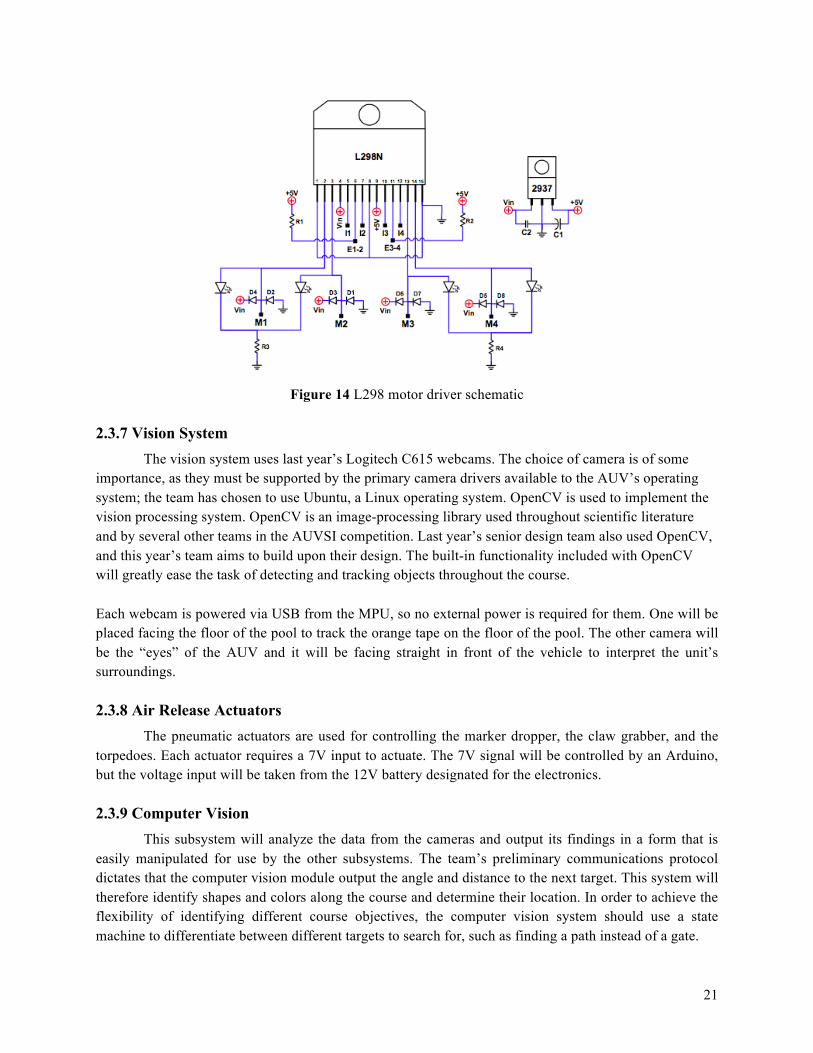
2.3.6 Motor Controller To control each thruster an L298 dual H bridge driver is selected for interpreting the PWM signal
from an Arduino. Essentially, each thruster is given a duty cycle range to accompany the necessary voltages the thruster requires to speed up and slow down. To control this, an Arduino will send PWM signals to the motor driver, where it will then take the voltage from the batteries and adjust the voltage output according to the duty cycle designated by the Arduino controllers.
" Operate at 6 to 26V " 4A Total Drive Current " Requires 5V for board power " Motor Direction indicator LED’s " EMF Protection diodes
These are parts from last year. However, research was done to assure that they met the requirements of the competition. The existing motor drivers perform as needed and work well with the PWM signals from the Arduino. The greatest perk to these motor drivers is the ability to handle the higher voltages. Many motor controllers that can handle comparable voltages cost quite a bit more.
21
Figure 14 L298 motor driver schematic
2.3.7 Vision System The vision system uses last year’s Logitech C615 webcams. The choice of camera is of some importance, as they must be supported by the primary camera drivers available to the AUV’s operating system; the team has chosen to use Ubuntu, a Linux operating system. OpenCV is used to implement the vision processing system. OpenCV is an image-processing library used throughout scientific literature and by several other teams in the AUVSI competition. Last year’s senior design team also used OpenCV, and this year’s team aims to build upon their design. The built-in functionality included with OpenCV will greatly ease the task of detecting and tracking objects throughout the course. Each webcam is powered via USB from the MPU, so no external power is required for them. One will be placed facing the floor of the pool to track the orange tape on the floor of the pool. The other camera will be the “eyes” of the AUV and it will be facing straight in front of the vehicle to interpret the unit’s surroundings.
2.3.8 Air Release Actuators The pneumatic actuators are used for controlling the marker dropper, the claw grabber, and the
torpedoes. Each actuator requires a 7V input to actuate. The 7V signal will be controlled by an Arduino, but the voltage input will be taken from the 12V battery designated for the electronics.
2.3.9 Computer Vision This subsystem will analyze the data from the cameras and output its findings in a form that is
easily manipulated for use by the other subsystems. The team’s preliminary communications protocol dictates that the computer vision module output the angle and distance to the next target. This system will therefore identify shapes and colors along the course and determine their location. In order to achieve the flexibility of identifying different course objectives, the computer vision system should use a state machine to differentiate between different targets to search for, such as finding a path instead of a gate.
22
2.3.10 Movement Controller The movement controller will accept information regarding the distance to its next target, as well
as its angle with respect to the AUV. It will then direct the output of the thrusters to reach the target position as nearly as possible, while accounting for the drift and inertia inherent to underwater movement. The mathematical model of the controller will be worked out separately, and then implemented in software.
2.3.11 Self-Positioning System The self-positioning system will use the IMU and the computer vision data to determine where
the AUV is with respect to its destination. The self-positioning system can then provide this data to the movement controller or to the task completion system to allow for intelligent corrections. The output protocol has not been decided yet, as it is pending further development of the artificial intelligence system in the sub. This module will decide whether the main system believes a task to have been completed.
2.3.12 Task Completion System This system is not required for the operation of the AUV, although it may be useful in allowing
the AUV to account for unexpected situations. As such, this system has been deemed optional, and will only be implemented if the team has time to do so. This system will examine the outputs of the three main operational modules and determine if they are in agreement with each other. This system may also attempt to determine whether other tasks have been completed, such as ascertaining whether an object has been picked up, a gate has been passed, or a marker has been dropped.
In its final implementation, the task completion system should have the final say on the completed status of the current task, and on whether a task should be paused and continued later if it cannot be completed at this time. For debugging purposes, the team may also choose to implement a tracking system to monitor which tasks have been completed; such a system would also be maintained by this module.
2.4 Performance Assessment All requirements of the AUV were identified in the Needs Analysis and Requirements
Specifications. This section will detail the design decisions made in order to satisfy each requirement and capability.
2.4.1 Required Capabilities Assessment For a complete list of requirements and capabilities, please see the team’s Needs Analysis and
Requirements Document. CAP-001 states that the RoboSub must autonomously complete all objectives. The implementation of software system described in Section 3.3 shall allow the AUV to store a preprogrammed set of actions in memory and execute them at system startup. The software system shall be sufficient in guiding the subs every move without external interaction.
CAP-002 through CAP-008 will all be satisfied by a similar approach. The primitive actions that the AUV must undergo each tasks described by each capability will be analyzed an encapsulated by an
23
algorithm. This algorithm will be implemented by the realization of the software system that guides the AUV through each objective.
2.4.2 Requirements Assessment
REQF-0004, a requirement of autonomous operation has been covered by the capabilities assessment. REQF-0003 and REQF-0005 refer to having the required equipment on the AUV during the competition. Since all equipment required to complete the tasks will need to be on the AUV and function before the AUV can function, this will surely be achieved. REQF-0001: The RoboSub should be under 85 lbs.
The team has taken this requirement into account by reducing the amount of extruded aluminum used from last year’s design. The new frame uses roughly half of the material. The hull is anticipated to be heavier than last year’s design, but preliminary calculations show that there should be an overall reduction of weight in total. Last year’s design was a bit over 85 pounds, but this year’s modifications are expected to reduce the weight to the target of under 85.
REQF-0002: The entire AUV shall be no larger 6’ long, 3’ wide, and 3’ high. The team has assured that no dimensions of the constructed frame exceed the target dimensions.
REQF-0006: Markers and torpedoes used by the AUV cannot be larger than 2”x2”x6” and weigh more than 2 lbs in air. They must also bear the team name or emblem.
Suitable markers and torpedoes have already been constructed, although the team will need to place their emblem upon them.
REQF-0007: The AUV must be able to be supported in a sling for weighing and transportation purposes. A secure sling will be constructed to firmly maintain stability for weighing and transportation requirements as the competition requires.
2.5 Design Process When designing the hull, several options were available. The first was to leave the hull as it was
and simply continue to use it. The second was to alter the end caps for easier access and reuse the rest of the hull and frame. The third was to redesign the hull from scratch and create a new, more accessible hull.
Redesigning the hull from scratch was not the most cost efficient option. Nonetheless it was selected because it became evident that even with modified caps the hull left behind by the previous team had various flaws that could not be addressed without a complete redesign. Since ease of access was a priority, the new design took the shape of a box with a removable lid.
Last’s year team expressed a concern with the power system. They burned out a few of their voltage regulators because their entire system operated on one battery, making it difficult to tailor the voltage to the different subsystems. This proved to be highly complicated and inefficient. A decision was made to modify this into 3 different, independent power systems. Each system will have its own battery and will power different components.
2.6 Overall Risk Assessment

24
This project contains many risky aspects because it is a large project with many separate and expensive components working in unison, and trying to complete the system within a time frame for competition.
Risk Level of Risk
Explanation
Damaging components of RoboSub during testing or transportation.
Medium Damaging components of RoboSub would require money, time, and a halt on testing. All of these things are vital to completing our task.
Completing RoboSub in time for Competition
High The scope of the project compared with what the team has accomplished thus far into the year is not falling into line.
Running out of funding for components
Medium Currently, major components and parts for the RoboSub have the necessary funding required to order them. However, if more are needed there may not be funding.
Having to redesign a feature due to poor design
Medium Taking careful precautions and factors of safety in the design process now will ensure working features that hopefully will not need redesigning. For instance, the AUV mechanical design had to be completely redone from last year’s because of poor design features.
Wrong parts delivered Low If the manufacturer, mechanical department, or a team member messes up in the process of ordering necessary parts, the project will have to be put on hold until a replacement part comes in.
Being behind schedule Low With setbacks from a task taking longer than previously thought, waiting for a team member to finish a part, or having to wait on a part to be shipped.
Table 2 Risk Assessment
3 Test Plan In order to have an end working product of a fully autonomous underwater vehicle, many tests and diagnostics are needed. Testing each subsystem so that they work and function properly is key to having a complex electrical, computer, and mechanical device working in unison. Most testing of components that are being used again from last year’s team can and have been done already. Other testing has still yet to be completed due various delays encountered by the team. This section of the report details the testing procedure of all components of the sub.

25
3.1 System and Integration Test Plan The AUV will undergo several system level tests to verify its functionality. A test program that instructs the AUV to travel in a square will be implemented. As a result of this test, the hull should not leak, all electronic boards and components should remain functional, and the AUV should successfully travel in a square.
To test the vision system of the sub, a ball will be suspended a specified distance away from the AUV. Once the AUV is ten feet away from the ball, the AUV will make a ninety-degree right turn. This test assesses the ability of the AUV to identify objects, calculate distance information, and take the necessary movements.
3.2 Test Plan for Major Components In order to ensure that the AUV meets all functional requirements and capabilities, a detailed test
plan must be executed as part of the AUV development. This section details the test plan for each major component of the AUV.
3.2.1 Power System Test Plan Each battery will be tested using a multimeter. Doing this will verify that the output voltage and amperage is correct in comparison to it’s specifications. After each battery has been tested, the next step is to connect them to their prospective subsystem and test their functionality. With a multimeter active, measuring both current and voltage, the subsystem will be turned on to make sure that it works with each power source.
3.2.2 Electronics Test Plan Each sensor has its own test procedure to verify its functionality. As many electronic components
such as Arduino boards are off-the-shelf components, their functionality tests are trivial and will not be discussed. 3.2.2.1 Power/Electronics System Integration
After each system has been individually verified, these two systems will need to be integrated. Due to each system having its own requirements, few issues should be encountered in integration. When integrated, all electronics should be in its fully functional, powered state.
3.2.3 Software System Test Plan
3.2.3.1 Top-Level Control Module Test Plan The development of the top-level control module will begin by creating a ‘mockup’ of the level
system. Essentially, each function that will be created will be declared with their actual interfaces; however, the function’s implementation will be simply to return the expected output. At this point, the interfaces between the top level and other modules will be verified before the real function is completed.

26
The expected communication between functions will be compared against the actual communication seen during testing.
Once all of the prototypes and their interfaces have been verified, the functions will be defined. Each function will be tested for the range of possible inputs that it will receive. The actual output will be compared against the expected output. After this is done, the top-level module is verified and ready for integration with the vision system.
3.2.3.2 Vision System Test Plan Tests images will be generated for vision modules. The test images generated as input for the
developing functions shall be numerous enough to fully test all of the requirements of the function. The actual output of the function under test will be compared against an expected output. Once the actual and expected outputs match, the function will be declared ready for use.
3.2.3.3 Software System Integration
Once the development and test plans have progress to completion for each portion of the software system, system integration shall begin. Due to the previous tests, a clear interface provided through the top-level control module, and the principal designers of these modules working in tandem, few system integration errors are expected. For a successful system integration test, the software system must be implemented on a functional AUV in a test course designed to mirror that seen in competition. Additional system testing methods may be necessary due to testing resource limitations.
3.2.4 Electronics Housing Test Plan Once the housing is completely built, testing on it will begin. The housing will be submerged in a
pool to test for any leaks in the welds and lid. Tissue papers will be placed inside to indicate if any water has gotten inside.
3.3 Summary of Test Plan Status
Task Date Completed/Planned
Result (Pass/Fail) Reason (if fail)
Test Thrusters/Arduinos
10/15/2012 Fail Improper motor driver documentation
Test Thrusters/Arduinos
11/13/2012 Pass
Hydrophones 10/16/2012 Fail Improper testing procedure
Table 3 Risk Assessment

27
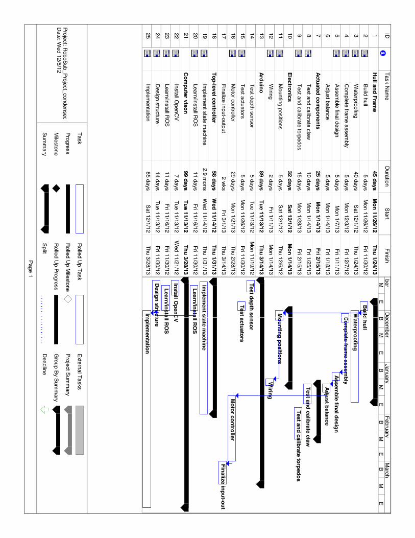
4 Schedule A Gantt chart illustrating the latest schedule can be found in the appendix. There are a few items
of interest that can be gathered from the Gantt chart. Firstly, it can be noted that programming tasks account for a large portion of the anticipated time to complete the project. Programming was one of the points where the previous year’s team encountered the most setbacks, so attempt was made to incorporate sufficient time for the tasks. The second item of note is the fact that a few of the tasks are behind schedule. Deviations from the included schedule have been caused by receiving incorrect orders from component supply companies and having far greater difficulty setting up the chosen software.
The team is making a concerted effort to compensate for lost time. The mechanical sub-team has decided to forego the planned miniature prototype of the AUV hull and move right to production of the full-scale model. Parts for the full-sized hull are already on order and delivery is expected soon. Fabrication and testing will begin at an accelerated rate once the components arrive.
Lengthy work sessions have been arranged to install the required software. Currently, both OpenCV and ROS are installed and functional, but they have not been integrated. Attempts to integrate the two have as of yet been unsuccessful. Since the integration of the two may not be critical for the successful completion of the project, emphasis has been placed on working with OpenCV, which will be used heavily by multiple subsystems. The team members with the most programming knowledge have been reassigned to work with the vision software due to the sheer difficulty of this portion of the project.
Even with the aforementioned setbacks, we still anticipate completing the project ahead of the July competition. The schedule was planned with a buffer period of over two months to allow for potential delays.
5 Budget Estimate
For the completion of this project, the team was allocated a total of 2,200 dollars. A budget plan was made as follows:
" Electrical Components: $880 " Mechanical Components: $880 " Prototype/Testing: $220 " Emergency Fund: $220
The working components that last year’s team left have spared some expenses, but some purchases such as raw material for the electronics housing and main computer needed to be made. At this moment the team has a total of $863.76 left. These funds are distributed as follows:
" Electrical Components: $92.53 " Mechanical Components: $336.20 " Prototype/Testing: $220 " Emergency Fund: $220
28
The remainder of the funds the team has will go into any changes that are made (if any) to the submarine. Once it is up and running, different parts such as PVC pipes will be bought to create a practice course for the submarine. The biggest expense the team faces is the travel costs to the competition. This includes transportation, food, and lodging for the entire team. The remaining budget is not enough to send the team to competition. Potential sponsors have been approached with hopes of obtaining more funding for the team.
6 Conclusion Much has been accomplished in the past three months. The hard work of the entire team has
yielded a complete design ready for fabrication. Components have been selected for all subsystems and are either received or currently awaiting delivery. Testing has demonstrated the ability to interface with thrusters and some of the sensors. In addition, we are in the early stages of developing the vision software.
Despite a few delays in initial setup of computer systems and acquisition, it is still anticipated that the project will achieve a sufficient level of completion to participate in the competition. Regardless of whether this design competes, the robustness and flexibility of the design demonstrate a high level of forward thinking and should prove to be an excellent platform for future FAMU-FSU teams.
7 References "RoboSub Competition Rules." AUVSI Foundation. Web. 11 Dec. 2012.
Appendices On the following page can be found the Gantt chart for the current 2012–2013 schedule.
IDTask Nam
eDuration
StartFinish
1Hull and Fram
e45 days
Mon 11/26/12
Thu 1/24/132
Build hull5 days
Mon 11/26/12
Fri 11/30/123
Waterproofing
40 daysSat 12/1/12
Thu 1/24/134
Complete fram
e assembly
5 daysM
on 12/3/12Fri 12/7/12
5Assem
ble final design5 days
Mon 1/7/13
Fri 1/11/136
Adjust balance5 days
Mon 1/14/13
Fri 1/18/137
Actuated components
25 daysM
on 1/14/13Fri 2/15/13
8Test and calibrate claw
10 daysM
on 1/14/13Fri 1/25/13
9Test and calibrate torpedos
15 daysM
on 1/28/13Fri 2/15/13
10Electronics
32 daysSat 12/1/12
Mon 1/14/13
11M
ounting positions5 days
Sat 12/1/12Thu 12/6/12
12W
iring2 days
Fri 1/11/13M
on 1/14/1313
Arduino89 days
Tue 11/13/12Thu 3/14/13
14Test depth sensor
5 daysTue 11/13/12
Mon 11/19/12
15Test actuators
5 daysM
on 11/26/12Fri 11/30/12
16M
otor controller29 days
Mon 1/21/13
Thu 2/28/1317
Finalize input-output2 wks
Fri 3/1/13Thu 3/14/13
18Top-level controller
58 daysW
ed 11/14/12Thu 1/31/13
19Im
plement state m
achine2.9 m
onsW
ed 11/14/12Thu 1/31/13
20Learn/install RO
S11 days
Fri 11/16/12Fri 11/30/12
21Com
puter vison99 days
Tue 11/13/12Thu 3/28/13
22Install O
penCV7 days
Tue 11/13/12W
ed 11/21/1223
Learn/install ROS
11 daysFri 11/16/12
Fri 11/30/1224
Design structure14 days
Tue 11/13/12Fri 11/30/12
25Im
plementation
85 daysSat 12/1/12
Thu 3/28/13
Build hullW
aterproofingCom
plete frame assem
blyAssem
ble final designAdjust balance
Test and calibrate clawTest and calibrate torpedos
Mounting positions
Wiring
Test depth sensorTest actuators
Motor controller
Finalize input-out
Implem
ent state machine
Learn/install ROS
Install OpenCV
Learn/install ROS
Design structureIm
plementation
ME
BM
EB
ME
BM
EB
ME
berDecem
berJanuary
FebruaryM
arch
Task
Progress
Milestone
Summ
ary
Rolled Up Task
Rolled Up Milestone
Rolled Up Progress
Split
External Tasks
Project Summ
ary
Group By Sum
mary
Deadline
Page 1
Project: RoboSub_Project_condensedDate: W
ed 12/5/12